US10564062B2 - Human-machine interface for gas valve - Google Patents
Human-machine interface for gas valveDownload PDFInfo
- Publication number
- US10564062B2 US10564062B2US15/297,876US201615297876AUS10564062B2US 10564062 B2US10564062 B2US 10564062B2US 201615297876 AUS201615297876 AUS 201615297876AUS 10564062 B2US10564062 B2US 10564062B2
- Authority
- US
- United States
- Prior art keywords
- valve
- test
- hmi
- pressure
- valve assembly
- Prior art date
- Legal status (The legal status is an assumption and is not a legal conclusion. Google has not performed a legal analysis and makes no representation as to the accuracy of the status listed.)
- Expired - Fee Related, expires
Links
Images


Classifications
- G—PHYSICS
- G01—MEASURING; TESTING
- G01M—TESTING STATIC OR DYNAMIC BALANCE OF MACHINES OR STRUCTURES; TESTING OF STRUCTURES OR APPARATUS, NOT OTHERWISE PROVIDED FOR
- G01M3/00—Investigating fluid-tightness of structures
- G01M3/02—Investigating fluid-tightness of structures by using fluid or vacuum
- G01M3/26—Investigating fluid-tightness of structures by using fluid or vacuum by measuring rate of loss or gain of fluid, e.g. by pressure-responsive devices, by flow detectors
- G01M3/28—Investigating fluid-tightness of structures by using fluid or vacuum by measuring rate of loss or gain of fluid, e.g. by pressure-responsive devices, by flow detectors for pipes, cables or tubes; for pipe joints or seals; for valves ; for welds
- G01M3/2876—Investigating fluid-tightness of structures by using fluid or vacuum by measuring rate of loss or gain of fluid, e.g. by pressure-responsive devices, by flow detectors for pipes, cables or tubes; for pipe joints or seals; for valves ; for welds for valves
- F—MECHANICAL ENGINEERING; LIGHTING; HEATING; WEAPONS; BLASTING
- F16—ENGINEERING ELEMENTS AND UNITS; GENERAL MEASURES FOR PRODUCING AND MAINTAINING EFFECTIVE FUNCTIONING OF MACHINES OR INSTALLATIONS; THERMAL INSULATION IN GENERAL
- F16K—VALVES; TAPS; COCKS; ACTUATING-FLOATS; DEVICES FOR VENTING OR AERATING
- F16K37/00—Special means in or on valves or other cut-off apparatus for indicating or recording operation thereof, or for enabling an alarm to be given
- F16K37/0075—For recording or indicating the functioning of a valve in combination with test equipment
- F16K37/0091—For recording or indicating the functioning of a valve in combination with test equipment by measuring fluid parameters
- F—MECHANICAL ENGINEERING; LIGHTING; HEATING; WEAPONS; BLASTING
- F23—COMBUSTION APPARATUS; COMBUSTION PROCESSES
- F23K—FEEDING FUEL TO COMBUSTION APPARATUS
- F23K5/00—Feeding or distributing other fuel to combustion apparatus
- F23K5/002—Gaseous fuel
- F23K5/007—Details
- F—MECHANICAL ENGINEERING; LIGHTING; HEATING; WEAPONS; BLASTING
- F23—COMBUSTION APPARATUS; COMBUSTION PROCESSES
- F23N—REGULATING OR CONTROLLING COMBUSTION
- F23N1/00—Regulating fuel supply
- F23N1/002—Regulating fuel supply using electronic means
- F—MECHANICAL ENGINEERING; LIGHTING; HEATING; WEAPONS; BLASTING
- F23—COMBUSTION APPARATUS; COMBUSTION PROCESSES
- F23K—FEEDING FUEL TO COMBUSTION APPARATUS
- F23K2900/00—Special features of, or arrangements for fuel supplies
- F23K2900/05002—Valves for gaseous fuel supply lines
- F23N2023/08—
- F23N2025/04—
- F23N2035/12—
- F23N2041/08—
- F—MECHANICAL ENGINEERING; LIGHTING; HEATING; WEAPONS; BLASTING
- F23—COMBUSTION APPARATUS; COMBUSTION PROCESSES
- F23N—REGULATING OR CONTROLLING COMBUSTION
- F23N2223/00—Signal processing; Details thereof
- F23N2223/08—Microprocessor; Microcomputer
- F—MECHANICAL ENGINEERING; LIGHTING; HEATING; WEAPONS; BLASTING
- F23—COMBUSTION APPARATUS; COMBUSTION PROCESSES
- F23N—REGULATING OR CONTROLLING COMBUSTION
- F23N2225/00—Measuring
- F23N2225/04—Measuring pressure
- F—MECHANICAL ENGINEERING; LIGHTING; HEATING; WEAPONS; BLASTING
- F23—COMBUSTION APPARATUS; COMBUSTION PROCESSES
- F23N—REGULATING OR CONTROLLING COMBUSTION
- F23N2235/00—Valves, nozzles or pumps
- F23N2235/12—Fuel valves
- F—MECHANICAL ENGINEERING; LIGHTING; HEATING; WEAPONS; BLASTING
- F23—COMBUSTION APPARATUS; COMBUSTION PROCESSES
- F23N—REGULATING OR CONTROLLING COMBUSTION
- F23N2241/00—Applications
- F23N2241/08—Household apparatus
- F—MECHANICAL ENGINEERING; LIGHTING; HEATING; WEAPONS; BLASTING
- F23—COMBUSTION APPARATUS; COMBUSTION PROCESSES
- F23N—REGULATING OR CONTROLLING COMBUSTION
- F23N2900/00—Special features of, or arrangements for controlling combustion
- F23N2900/05005—Mounting arrangements for sensing, detecting or measuring devices
Definitions
- the disclosurerelates generally to valves, and more particularly, to gas valve assemblies and mechanisms for interfacing with gas valve assemblies.
- Valvesare commonly used in conjunction with many appliances for regulating the flow of fluid.
- gas valvesare often incorporated into gas-fired appliances to regulate the flow of gas to a combustion chamber or burner.
- gas-fired appliancesmay include, but are not limited to, water heaters, furnaces, boilers, fireplace inserts, stoves, ovens, dryers, grills, deep fryers, or any other such device where gas control is desired.
- the gasmay be ignited by a pilot flame, electronic ignition source, or other ignition source, causing combustion of the gas at the burner element producing heat for the appliance.
- the gas valvein response to a control signal from a control device such as a thermostat or other controller, the gas valve may be moved between a closed position, which prevents gas flow, and an open position, which allows gas flow.
- the gas valvemay be a modulating gas valve, which allows gas to flow at one or more intermediate flow rates between the fully open position and the fully closed position.
- a valve leakage testmay be performed on a valve assembly including a valve body having an inlet port and an outlet port with a fluid path extending between the inlet port and the outlet port. Between the inlet port and the outlet port, the valve assembly may include a first gas valve and a second gas valve positioned downstream of the first gas valve, with an intermediate volume between the first gas valve and the second gas valve defined by the valve body.
- the first and second gas valvesmay be selectively movable between a closed position, which may close the fluid path, and an open position, by respective valve actuators.
- One or more pressure sensorsmay be in fluid communication with the intermediate volume for sensing a measure that is related to a pressure change rate in the intermediate volume.
- the pressure sensormay be in communication with a valve controller having memory or in communication with other memory storing one or more threshold values.
- the valve controllermay be configured to open the first valve and the second valve to allow gas to flow from the gas inlet to the gas outlet and close one or more of the first valve and the second valve to prevent gas flow from the gas inlet to the gas outlet.
- a human machine interfacemay be operatively coupled to the valve controller.
- the HMImay include a user interface with a display, where the user interface may include a start button that when selected may initiate the valve leakage test.
- an HMImay facilitate interacting with a valve assembly to initiate and/or monitor a valve test on the valve assembly.
- the HMImay include an interface for sending and/or receiving information, memory, a user interface including a display, and an HMI controller.
- the HMI controllermay be operatively coupled with the interface, the memory, and the user interface.
- the HMI controllermay receive an initiation of a test for the valve assembly via the user interface and send a signal to the valve assembly over the interface. The sent signal may initiate the valve test on the valve assembly.
- the HMImay be configured to initiate a valve leakage test on a gas assembly coupled to a non-switched or other gas source that is under a positive pressure during the valve leakage test.
- a usermay initiate a valve leakage test of the gas valve assembly by selecting a start button on a user interface of an HMI.
- the HMImay be configured to display received results of the valve leakage test on a display of the HMI in real time during the valve leakage test.
- FIG. 1is a schematic perspective view of an illustrative fluid valve assembly
- FIG. 2is a schematic diagram showing an illustrative fluid valve assembly in communication with a remote control system and an appliance control system, where the fluid valve assembly includes multiple sensors connected to a valve controller;
- FIG. 3is a schematic diagram showing an illustrative human machine interface interfacing with a valve assembly
- FIG. 4is a schematic diagram showing an illustrative setup status screen displayed on a display of a human machine interface
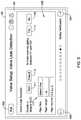
- FIG. 5is a schematic diagram showing an illustrative valve leak detection test set up screen displayed on a display of a human machine interface
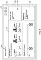
- FIG. 6is a schematic diagram showing an illustrative valve assembly status screen displayed on a display of a human machine interface
- FIG. 7is a schematic diagram showing an illustrative setup and tests screen displayed on a display of a human machine interface
- FIGS. 8A and 8Bare schematic diagrams showing illustrative valve leak detection monitoring screens displayed on a display of a human machine interface
- FIG. 9is a schematic diagram showing an illustrative diagnostics screen depicting valve assembly trends displayed on a display of a human machine interface
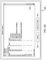
- FIGS. 10 and 11are schematic diagrams showing illustrative diagnostics screens depicting valve assembly reports displayed on a human machine interface
- FIGS. 12A-12Care a schematic diagrams showing an illustrative screen depicting a report as the screen is scrolled down.
- Gas valvesmay be used with fluid path systems supplying fuel and/or fluid to appliances (e.g., burners, etc.) or may be used individually or in different systems.
- gas safety shutoff valvesmay be utilized as automatic redundant valves. Redundancy is achieved, and often times required by regulatory agencies, by placing at least two safety shutoff valves in series.
- the aforementioned redundant valvesmay be separate valves fitted together in the field and/or valves located together in a single valve body. These redundant valves are commonly referred to as double-block valves.
- these and other gas valvesmay be fitted to include sensors and/or switches and/or other mechanical or electronic devices to assist in monitoring and/or analyzing the operation of the gas valve and/or connected appliance.
- the sensors and/or switchesmay be of the electromechanical type, the electronic type, or of other types of sensors and/or switches, as desired.
- a gas valve assemblymay be configured to monitor and/or control various operations including, but not limited to, monitoring fluid flow and/or fluid consumption, electronic cycle counting, overpressure diagnostics, high gas pressure and low gas pressure detection, valve proving system tests, valve leakage tests, proof of valve closure tests, diagnostic communications, and/or any other suitable operation as desired.
- Examples of gas valve assemblies used for monitoring and/or controlling such operationsare disclosed in U.S. application Ser. No. 13/326,358, now U.S. Pat. No. 8,947,242, filed on Dec. 15, 2011, and entitled GAS VALVE WITH LEAKAGE TEST, which is hereby incorporated by reference in its entirety for all purposes.
- FIG. 1is a schematic perspective view of an illustrative fluid (e.g., gas, liquid, etc.) valve assembly 10 for controlling fluid flow to a combustion appliance or other similar or different device.
- the gas valve assembly 10may include a valve body 12 , which may generally be a six sided shape or may take on any other shape as desired, and may be formed as a single body or may be multiple pieces connected together.
- valve body 12may be a six-sided shape having a first end 12 a , a second end 12 b , a top 12 c , a bottom 12 d , a back 12 e and a front 12 f , as depicted in FIG. 1 .
- the terms top, bottom, back, front, left, and rightare relative terms used merely to aid in discussing the drawings, and are not meant to be limiting in any manner.
- valve body 12may include an inlet port 14 , an outlet port 16 , and a fluid path or fluid channel 18 extending between inlet port 14 and outlet port 16 .
- valve body 12may include one or more gas valve ports 20 (e.g., a first valve port 20 a and a second valve port 20 b , shown in FIG. 2 ) positioned or situated in fluid channel 18 , one or more fuel or gas valve member(s) sometimes referred to as valve sealing member(s) moveable within gas valve ports 20 (e.g., a first valve sealing member within first valve port 20 a and a second valve sealing member within second valve port 20 b ), one or more pressure sensor assemblies 42 , 43 , 44 (as shown in FIG.
- valve controllers 26affixed relative to or coupled to valve body 12 and/or in electrical communication (e.g., through a wired or wireless connection) with pressure sensor assemblies 42 , 43 , 44 , and position sensor(s) 48 .
- the valve assembly 10may further include one or more actuators for operating moving parts therein.
- the valve assembly 10may have actuators including, but not limited to, one or more stepper motors 94 (shown as extending downward from the bottom 12 d of the valve body 12 in FIG. 1 ), one or more solenoids 96 (shown as extending upward from top 12 c of valve body 12 in FIG. 1 ), and one or more servo valves 98 (a servo valve 98 is shown as extending upward from the top 12 c of the valve body 12 in FIG. 1-3 , where a second servo valve has been omitted), where the servo valve 98 may be a 3-way auto-servo valve or may be any other type of servo valve.
- the one or more solenoids 96may control whether the one or more gas valve ports 20 are open or closed.
- the one or more stepper motors 94may determine the opening size of the gas valve ports 20 when the corresponding gas valve sealing member is opened by the corresponding solenoid 96 .
- the one or more stepper motors 94would not be provided when, for example, the valve assembly 10 is not a “modulating” valve that allows more than one selectable flow rate to flow through the valve when the valve is open.
- valve body 12may include one or more sensor and electronics compartments 56 , which in the illustrative embodiment, may extend from the back side 12 e as depicted in FIG. 1 .
- the sensor and electronics compartments 56may be coupled to or may be formed integrally with the valve body 12 , and may enclose and/or contain at least a portion of the valve controllers 26 , the pressure sensors assemblies 42 , 43 , 44 , the one or more electronic connection port 45 (e.g., USB, HDMI, and/or other data ports or other ports) and/or the electronics required for operation of valve assembly 10 as described herein.
- the compartments 56may be illustratively depicted as separate structures, the compartments 56 may be a single structure part of, extending from, and/or coupled to the valve body 12 .
- the one or more fluid valve ports 20may include the first gas valve port 20 a and the second gas valve port 20 b situated along and/or in communication with the fluid channel 18 .
- Thisis a double-block valve design.
- a gas valve sealing membermay be situated in fluid channel 18 and may be positioned (e.g., concentrically or otherwise) about an axis, rotatable about the axis, longitudinally and axially translatable, rotationally translatable, and/or otherwise selectively movable between a first position (e.g., an open or closed position) and a second position (e.g., a closed or open position) within the corresponding valve port 20 . Movement of the valve sealing member may open and close the valve port 20 .
- valve actuator(s) 30may be any type of actuator configured to operate valve sealing member by actuating valve sealing member from the closed position to an open position and then back to the closed position during each of a plurality of operation cycles during a lifetime of the gas valve assembly 10 and/or of actuator 30 .
- valve actuator 30e.g., a first valve actuator 30 a and a second valve actuator 30 b , as seen in FIG. 2
- valve actuator 30may be a solenoid actuator, a hydraulic actuator, magnetic actuators, electric motors, pneumatic actuators, and/or other similar or different types of actuators, as desired.
- valve actuators 30 a , 30 bmay be configured to selectively move valves or valve sealing members of the valve ports 20 a , 20 b between a closed position, which closes the fluid channel 18 between the inlet port 14 and the outlet port 16 of the valve body 12 , and an open position.
- the gas valve assembly 10 of FIGS. 1 and 2is an example of a gas safety shutoff valve, or double-block valve. In some cases, however, it is contemplated that the gas valve assembly 10 may have a single valve sealing member or three or more valve sealing members in series or parallel, as desired.
- valve assembly 10may include a characterized port defined between the inlet port 14 and the outlet port 16 .
- a characterized portmay be any port (e.g., a fluid valve port 20 or other port or restriction through which fluid channel 18 may travel) at or across which an analysis may be performed on a fluid flowing therethrough.
- the characterized portmay be a port 20 having valve sealing member configured to be in an open position and in a closed position.
- a characterized portmay not correspond to a gas valve port 20 having valve sealing member. Rather, the characterized port may be any constriction or feature across which a pressure drop may be measured and/or a flow rate may be determined.
- the characterized portmay be characterized at various flow rates to identify a relationship between a pressure drop across the characterized port and the flow rate through the fluid channel 18 .
- the pressure dropmay be measured directly with one or more pressure sensors (e.g., pressure sensors 42 , 43 , and/or 44 ).
- the pressure dropmay be inferred from, for example, the current position of the valve member(s). These are just some examples.
- the relationshipmay be stored in a memory, such as a RAM, ROM, EEPROM, other volatile or non-volatile memory, or any other suitable memory of the gas valve assembly 10 , but this is not required.
- the gas valve assembly 10may include a flow module 28 for sensing one or more parameters of a fluid flowing through fluid channel 18 , and in some cases, determining a measure related to a gas flow rate of the fluid through the fluid channel 18 .
- the flow modulemay include a pressure block or pressure sensor assembly (e.g., in some cases, the pressure sensors 42 , 43 , 48 ), a temperature sensor 34 (e.g., in some cases, temperature sensors 34 a , 34 b , and/or 34 c ), a valve member position sensor 48 (e.g., in some cases, position sensors 48 a , 48 b ), and/or a valve controller 26 , among other assemblies, sensors and systems for sensing, monitoring and/or analyzing parameters of a fluid flowing through the fluid channel 18 , such as can be seen in FIG. 2 .
- a flow module 28may utilize any type of sensor to facilitate determining a measure related to a flow rate of a fluid through the fluid channel 18 , such as a pressure sensor, a flow sensor, a valve position sensor, and/or any other type of sensor, as desired.
- the flow module 28may be configured to monitor a differential pressure across one or more characterized port, and in some cases, a position of one or more valve sealing members of the gas valve assembly 10 . The information from monitoring may be utilized by the flow module 28 to determine and/or monitor the flow rate of fluid (liquid or gas) passing through the fluid channel 18 .
- the flow module 28may determine a measure that is related to a gas flow rate through the fluid channel 18 based, at least in part, on the measure that is related to the pressure drop across the characterized port along with the pre-stored relationship in the memory.
- the current position of one or more valve sealing members of the gas valve assembly 10may also be taken into account (e.g. is the valve 30% open, 50% open or 75% open).
- the flow module 28may be configured to output the flow rate of fluid passing through the fluid channel 18 to a display and/or a remote device. In some cases, the flow module may maintain a cumulative gas flow amount passing through the fluid channel 18 (e.g. over a time period), if desired.
- the measure related to a gas flowmay include, but is not limited to, a measure of fuel consumption by a device or appliance that is connected to an output port 16 of the gas valve assembly 10 .
- valve controller or valve control block 26may be physically secured or coupled to, or secured or coupled relative to, the valve body 12 (e.g., in some cases, within one or more of the sensor and electronics compartments 56 ).
- the valve controller 26may be configured to control and/or monitor a position or state (e.g., an open position and a closed position) of valve sealing members of valve ports 20 and/or to perform other functions and analyses, as desired.
- valve control block 26may be configured to close or open gas valve member(s) or valve sealing member(s) on its own volition, in response to control signals from other systems (e.g., a system level or central building control), and/or in response to received measures related to sensed pressures upstream, intermediate, and/or downstream of the characterized valve port(s), measures related to a sensed differential pressure across the characterized valve port(s), measures related to temperature sensed upstream, intermediate, and/or downstream of the characterized valve port(s), and/or in response to other measures, as desired.
- other systemse.g., a system level or central building control
- the memorywhich in some cases may be part of the valve controller 26 , may be configured to record data related to sensed pressures, sensed differential pressures, sensed temperatures, and/or other measures.
- the valve controller 26may access this data, and in some cases, communicate (e.g., through a wired or wireless communication link 100 ) the data and/or analyses of the data to other systems (e.g., a system level or central building control).
- the memorymay be programmed and/or developed to contain software to effect one or more of the configurations described herein.
- valve controller 26may be considered a portion of flow module 28 , the flow module 28 may be considered part of the valve controller 26 , or the flow module 28 and the valve controller 26 may be considered separate systems or devices.
- the valve controller 26may be coupled relative to the valve body 12 and one or more gas valve ports 20 , where the valve controller 26 may be configured to control a position (e.g., open or closed positions, including various open positions) of valve sealing member within the valve port 20 .
- the valve controller 26may be coupled to pressure sensor assembly 42 , 43 , 44 , temperature sensor 34 , position sensor 48 , and/or other sensors and assemblies, as desired.
- the valve controller 26may be configured to monitor a differential pressure across a characterized port. In some instances, the valve controller 26 may monitor a differential pressure across the fluid valve port 20 and/or monitor a measure related to a pressure upstream of a fluid valve port 20 (e.g., the first valve port 20 a ) and/or a measure related to a pressure downstream of a fluid valve port 20 (e.g., the second valve port 20 b ). The valve controller 26 may also be configured to monitor an axial position of the valve sealing member in the valve port 20 .
- the valve controller 26may determine a flow rate of fluid passing through the characterized port, where the valve controller 26 may determine the flow rate (and sometimes fluid consumption) based, at least in part, on the monitored differential pressure and/or monitored upstream and downstream pressures in conjunction with a pre-characterized relationship between the pressure drop across the characterized port and the flow rate.
- the monitored axial positioning of the valve sealing membermay also be taken into account, particularly when the valve sealing member may assume one or more intermediate open positions between the fully closed and fully opened positions.
- the pre-characterized relationship between the pressure drop across the characterized port and the flow ratemay depend on the current axial positioning of valve sealing member.
- the valve controller 26may include a determining block, which may include the microcontroller 36 or the like, which may include or be in communication with a memory 37 , such as a non-volatile memory.
- the determining blocke.g. microcontroller 36
- the determining blockmay be coupled to or may be configured within valve control block or valve controller 26 .
- the determining blockmay be configured to store and/or monitor one or more parameters, which may be used when determining a measure that is related to a fluid flow rate through fluid channel 18 .
- the determining block(e.g. microcontroller 36 ) may be configured to use the stored and/or monitored parameters (e.g. the relationship between a pressure drop across a characterized port and the flow rate through the fluid channel 18 ) stored in the memory to help determine a measure that is related to a fluid flow rate through the fluid path or fluid channel 18 .
- the determining blockmay be configured to determine and/or monitor a measure (e.g., a flow rate of fluid passing through the characterized port or other similar or different measure, as desired) based, at least in part, on stored and/or monitored measures including, but not limited to, measures related to pressure drop across a characterized valve port or other pressure related measures upstream and downstream of the characterized valve port, a temperature of the fluid flowing through fluid channel 18 , and/or a measure related to a current position of valve sealing member at the valve port 20 or the size of an opening at the characterized port.
- a determining blocke.g.
- microcontroller 36may include non-volatile memory that is configured to store opening curves of the valve assembly 10 , where the opening curves may characterize, at least in part, a flow rate as a function of a sensed axial position of valve sealing member, and a sensed differential pressure across a characterized valve port 20 or an otherwise determined pressure at or adjacent a characterized valve port 20 (e.g., knowing a set-point of an upstream pneumatic pressure reducing valve (PRV), as the set-point pressure of the PRV may be substantially equal to the pressure at an inlet of the characterized valve port), and may facilitate determining an instantaneous and/or cumulative fluid (e.g., fuel) flow in fluid channel 18 and/or consumption by an appliance in fluid communication with valve assembly 10 .
- PRVupstream pneumatic pressure reducing valve
- the determining blockmay continuously or non-continuously control, store, and/or monitor a position (e.g., an axial or rotary position or open/closed state or other position) of the valve sealing member within the valve port 20 , monitor a differential pressure across the characterized port, and/or monitor a temperature upstream and/or downstream of the characterized port.
- a positione.g., an axial or rotary position or open/closed state or other position
- the microcontroller 36may continuously or non-continuously determine the flow rate of the fluid passing through the characterized port, where the microcontroller 36 may be configured to record in its memory or in another location, an instantaneous flow rate of fluid flowing through the characterized port, a cumulative flow volume, and/or a determined instantaneous or cumulative (e.g., total) fluid consumption based on the positions of valve sealing member(s) and determined flow rates at an instant of time or over a specified or desired time period.
- the determining blocke.g. microcontroller 36
- the determining blocke.g.
- microcontroller 36may report the instantaneous flow rate, cumulative flow rate, and/or total or cumulative consumption of the fluid flowing through the characterized port to the system display 52 of a remote overall system controller 50 (e.g., a building/industrial automation system (BAS/IAS) controller), an appliance display 62 of an appliance controller 60 where the appliance may be configured to receive the flowing fluid, a display adjacent the gas valve assembly 10 , or any other display, device, controller and/or memory, as desired.
- a remote overall system controller 50e.g., a building/industrial automation system (BAS/IAS) controller
- BAS/IASbuilding/industrial automation system
- valve controller 26may include or be in communication with a valve actuator 30 , which in conjunction with the stepper motor 94 or other device is configured to position the valve sealing member in the valve port 20 .
- the valve actuator 30 and/or stepper motor 94may be in communication with the microcontroller 36 of the valve controller 26 , and the microcontroller 36 may be configured to control, monitor, and/or record the position (e.g., axial position, radial position, etc.) of the valve sealing member within the valve port 20 through the valve actuator 30 (e.g., valve actuator 30 may be configured to effect the locking (e.g., valve actuator 30 OFF) or the unlocking (e.g., valve actuator 30 ON) of the valve sealing member in a particular position) and the stepper motor 94 (e.g., the stepper motor 94 may be configured to adjust the position of valve sealing member when it is not locked in a particular position), or through only the stepper motor 94 .
- the microcontroller 36may be configured to monitor
- the microcontroller 36may continuously or non-continuously monitor and record the position (e.g., axial position, radial position, etc.) of the valve sealing member within valve port 20 through the valve actuator 30 and the stepper motor 94 , and the microcontroller 36 may indicate the sensed and/or monitored position of valve sealing member within the valve port 20 as a prescribed position of the valve sealing member.
- the prescribed position of valve sealing membermay be the position at which the valve sealing member was and/or is to be located, whereas a position of the valve sealing member sensed by the position sensor system 48 may be considered an actual position of the valve sealing member within the valve port 20 .
- valve controller 26may be configured to perform electronic operational cycle counting or may include an electronic counter configured to count each operational valve cycle of valve sealing members during, for example, the lifetime of gas valve assembly 10 or during some other time period.
- the microprocessor 36 of the valve controller 26may be configured to monitor a total number of operational cycles (e.g., the number of times fuel valve sealing members are operated from a closed position to an open position and back to a closed position) of the valve ports 20 and measures related thereto.
- the microprocessor 36may store such data in a non-volatile memory, such as the memory 37 , sometimes in a tamper proof manner, for record keeping and/or other purposes.
- the microprocessor 36may monitor the number of cycles of valve sealing members in one or more of several different manners. For example, microprocessor 36 may monitor the number of cycles of the valve sealing members by monitoring the number of times first main valve switch 72 and/or second main valve switch 74 are powered or, where one or more control signals may be provided to fuel valve actuator(s) 30 controlling when the fuel valve actuator(s) 30 selectively moves (e.g., opens or closes) valve sealing member(s), the microprocessor 36 may monitor the one or more control signals.
- the valve controller 26may monitor the main valve switches 72 , 74 by receiving signals directly from a device located remotely from the valve assembly 10 on which the main valve switches 72 , 74 may be located.
- Switches((main valve switches 72 , 74 and safety switch 70 (discussed below)) may be any mechanism capable of performing a switching function including, but not limited to, relays, transistors and/or other solid state switches and circuit devices and/or other switches.
- the valve controller 26may include an electrical port, sometimes separate from a communications interface 110 (discussed below), for receiving one or more control signals from the device located remotely from valve assembly 10 .
- the one or more control signals received via the electrical portmay include, but are not limited to: a first valve port 20 a control signal that, at least in part, may control the position of first valve sealing member via first valve actuator 30 a , and a second valve port 20 b control signal that, at least in part, may control the position of the second valve sealing member via second valve actuator 30 b.
- microprocessor 36may monitor the number of cycles of valve sealing members by monitoring data from a position sensor 48 .
- the microprocessor 36 of the valve controller 26may monitor the position sensor 48 and record the number of times the valve sealing members are in an open position after being in a closed position and/or the number of times valve sealing members are in a closed position after being in an open position and/or the number of times the valve sealing members are operated from a close position to an open position and back to a closed position. These are just some examples.
- the valve controller 26may monitor the number of operational cycles by counting its own control signals sent to the valve actuators 30 and/or the stepper motors 94 .
- the non-volatile memorywhich may maintain and/or store the number of operational valve cycles, may be positioned directly on, or packaged with, the valve body 12 (e.g., on or within memory of microcontroller 36 ) and/or may be accessible by valve controller 26 .
- Such storage, placement and/or packaging of valve cycle datamay allow for replacement of components in the overall system (e.g., an appliance control 60 , etc.) without losing the valve cycle data.
- valve cycle datamay be securely stored, such that it may not be tampered with.
- the valve cycle datamay be stored the non-volatile memory of the valve controller 26 and the valve cycle data may be password protected.
- the valve controller 26may include an I/O or communications interface 110 with a communication protocol for transmitting data to and/or otherwise communicating with one or more remote device(s) that may be located remotely from the valve assembly 10 (e.g., a combustion appliance including the controller 60 located remotely from valve assembly 10 , a remote human-machine interface, such as a remote diagnostics system, etc.) and/or located adjacent the device (e.g., a local human-machine interface, such as, a local diagnostics system, an installation tool, and/or maintenance tool).
- Communications interface 110may be a wired or wireless communication interface, where the wired or wireless communication interface 110 may be configured to be compatible with a predetermined communication bus protocol or other communication protocol.
- a wired linkmay be low voltage (e.g.
- communications interface 110may be configured to output and/or communicate one or more valve conditions, one or more measures related to valve conditions, one or more conditions related to a fluid flow through fluid channel 18 , and/or one or more diagnostic parameters, conditions or events, to a device located adjacent or remote from valve assembly 10 .
- the communications interface 110may include or may be in communication with electronic data port(s) 45 .
- the valve controller 26may be configured to determine one or more valve conditions based on one or more diagnostic parameters related to fluid channel 18 sensed by one or more sensor(s) (e.g., a pressure sensor, etc.) in communication with the fluid channel 18 .
- the diagnostic parametersmay be determined by the valve controller 26 and stored in a non-volatile memory or other memory accessible by the valve controller 26 .
- the diagnostic parametersmay include, but are not limited to, a total number of operational cycles, a fuel usage parameter, one or more fault history parameters, one or more user or factory or other setting parameters, self diagnostic check parameters, fault parameters and/or other similar or dissimilar parameters, as desired.
- the communicated valve condition(s) or measure(s) related to the valve condition(s)may be determined by the valve controller 26 or one or more remote devices.
- Illustrative valve conditions and measures related to valve conditionsmay include, but are not limited to: high fuel pressure conditions, low fuel pressure conditions, valve closure conditions, valve leak conditions, safety event condition, and/or other similar or dissimilar valve conditions and/or outputs.
- the communication interface 110may be configured to receive one or more inputs from the remote device or an adjacently positioned device.
- Illustrative inputsmay include, but are not limited to: an acknowledgement of reception of one or more of the valve conditions, a user setting, a system setting, a valve command, and/or other similar or dissimilar input.
- valve controller 26may communicate through the I/O interface or communication interface 110 with a remotely located output block, where the output block may display and/or output a determined measure related to fluid flow rate through the fluid channel 18 , sometimes along with other data, information and controls sent from the valve controller 26 .
- the output blockmay include a display and/or other remote systems, and the microcontroller 36 may be configured to send measures to a device control system 60 or building automation system or overall system controller 50 of the output block for further monitoring and/or analysis.
- the I/O interfacemay include a wired and/or wireless interface between valve controller 26 (e.g., microcontroller 36 ) and the output block systems (e.g., building automation system or overall system controller 50 , combustion appliance controller 60 , handheld device, laptop computer, smart phone, etc.), where the connection between the valve controller 26 may or may not be made with the communication link 100 (e.g., communication link 100 could, but need not be, the one and only one communication link).
- valve controller 26e.g., microcontroller 36
- the output block systemse.g., building automation system or overall system controller 50 , combustion appliance controller 60 , handheld device, laptop computer, smart phone, etc.
- the connection between the valve controller 26may or may not be made with the communication link 100 (e.g., communication link 100 could, but need not be, the one and only one communication link).
- a pressure block including the pressure sensor assembly 42 , 43 , 44may be included in the flow module and/or the pressure sensor assembly 42 , 43 , 44 may be at least partially separate from the flow module 28 .
- the pressure sensor assembly 42 , 43 , 44may be configured to continuously or non-continuously sense pressure or a measure related to pressure upstream and/or downstream of a characterized port and/or along other portions of the fluid channel 18 .
- the pressure sensor assembly 42 , 43 , 44may additionally, or alternatively, include a mass or volume flow meter to measure a flow of fluid through the fluid channel 18 , it has been contemplated that such meters may be more expensive and difficult to place within or outside the valve assembly 10 ; thus, a useful, relatively low cost alternative and/or additional solution may include placing the pressure sensors 42 , 43 , 44 and/or other pressure sensors within, about and/or integrated in the valve body 12 of valve assembly 10 to measure the fluid flow through the fluid channel 18 , the pressures at the input and output ports, and/or other similar or different pressure related measures.
- the pressure sensors 42 , 43 , 44may include any type of pressure sensor element.
- the pressure sensor element(s)may be MEMS (Micro Electro Mechanical Systems) pressure sensors elements or other similar or different pressure sensor elements such as an absolute pressure sense element, a gauge pressure sense element, or other pressure sense element as desired.
- Example sense elementsmay include, but are not limited to, those described in U.S. Pat. Nos. 7,503,221; 7,493,822; 7,216,547; 7,082,835; 6,923,069; 6,877,380, and U.S. patent application publications: 2010/0180688; 2010/0064818; 2010/00184324; 2007/0095144; and 2003/0167851, all of which are hereby incorporated by reference.
- the pressure sensor assembly 42 , 43 , 44may include a differential pressure sensor for measuring a differential pressure drop across a characterized valve port 20 , or across a different characterized port.
- a pressure sensor assembly 42 , 43 , 44 including a differential pressure sensormay be exposed to both a first pressure upstream of a characterized valve port and a second pressure downstream of the characterized valve port.
- a differential pressure sensormay send a measure related to the sensed differential pressure to the microcontroller 36 of the valve controller 26 .
- the microcontroller 36may be configured to monitor the differential pressure across the characterized port with the differential pressure measures sensed by the differential pressure sensor.
- the illustrative pressure sensors 42 , 43 , 44may include one or more first pressure sensors 42 upstream of a characterized valve port and one or more second pressure sensors 43 downstream of the characterized valve port, where the first and second pressure sensors 42 , 43 may be in fluid communication with the fluid channel 18 and may be configured to sense one or more measures related to a pressure upstream and a pressure downstream, respectively, of the characterized valve port, as seen in FIG. 2 .
- a second valve porte.g., second valve port 20 b
- a first characterized valve porte.g.
- first valve port 20 aand forming an intermediate volume 19 between the first and second valve ports 20 a , 20 b
- a third pressure sensors 44 in fluid communication with the intermediate volume 19may sense one or more measures related to a pressure in the intermediate volume 19 .
- the first pressure sensors 42may be upstream of both characterized ports
- the second pressure sensors 43may be downstream of both characterized ports
- the third pressure sensors 44may be downstream from the first characterized port and upstream from the second characterized, but this is not required (e.g., the first and second pressure sensors 42 , 43 may be used to estimate the pressure drop across the valves).
- one or more pressure sensors 42 , 43 , 44may be differential pressure sensors utilized to estimate the pressure drop across the first characterized port and/or the second characterized port. It is further contemplated that valve ports 20 may not be characterized ports.
- the pressure sensors 42 , 43 , 44may be configured to send each of the sensed measure(s) directly to the microcontroller 36 .
- the microcontroller 36may be configured to save the sensed measures and/or related information to the memory 37 (e.g., non-volatile memory or other memory), and may perform one or more analyses on the received sensed measures. For example, the microcontroller 36 may determine a measure that is related to a fluid flow rate through the fluid path, pressure drops across valve ports, and/or other analyses based, at least in part, on the received sensed measures related to pressure upstream of the characterized port and on the received sensed measures related to pressure downstream of the characterized port.
- the pressure sensors 42 , 43 , 44may be or include one or more absolute pressure sensors in communication with the microcontroller 36 .
- An absolute pressure sensormay sense an atmospheric pressure adjacent the gas valve assembly 10 , and may be configured to communicate and transfer data related to the sensed atmospheric pressure to the microcontroller 36 .
- the microcontroller 36may take into account the atmospheric pressure from the absolute pressure sensor when determining the flow rate of fluid flowing through the characterized port and/or an estimate of fuel consumption by an attached appliance and/or when determining threshold values.
- Other sensorsmay be included in valve assembly 10 , for example, one other type of sensor may be a barometric pressure sensor.
- the valve assembly 10 and the flow module thereofmay include temperature sensor(s) 34 .
- the temperature sensor 34may be positioned within valve body 12 so as to be at least partially exposed to fluid channel 18 and configured to sense a temperature of a fluid (e.g., gas or liquid) flowing through fluid channel 18 and/or any other temperature in fluid channel 18 .
- the temperature sensor 34may have a first temperature sensor 34 a at least partially exposed to the fluid channel 18 upstream of a characterized valve port, and/or a second temperature sensor 34 b at least partially exposed to the fluid channel 18 downstream of the characterized valve port, as seen in FIG. 2 .
- first valve port and a second valve portthere may be a third temperature sensor 34 c in fluid communication with intermediate volume 19 between the first and second characterized valve ports, if desired.
- the sensed temperature measuremay be used by flow module to, for example, compensate, correct, or modify a determined measure (e.g., a density of a fluid) that is related to, for example, a fluid flow rate of fluid flowing through fluid channel 18 , which may help improve the accuracy of the flow rate calculation.
- a determined measuree.g., a density of a fluid
- the temperature sensor 34may communicate a sensed temperature measure directly or indirectly to the valve controller 26 and/or a non-volatile memory or other memory of the valve controller 26 (e.g., memory in a microcontroller 36 or memory in another location) and/or flow module.
- a non-volatile memory or other memory of the valve controller 26e.g., memory in a microcontroller 36 or memory in another location
- the pressure sensors 42 , 43 , 44may utilize built-in temperature sensors that are used to internally compensate the pressure sensor over the operating temperature range. In such instances, the temperature reading may be accessible at the pressure sensor output (e.g., a digital communication bus) or at another location.
- the pressure sensor outpute.g., a digital communication bus
- the valve controller 26may, in turn, utilize the sensed temperature to help increase the accuracy of a determined flow rate of fluid passing through a characterized port and/or increase the accuracy of a calculated fluid and/or fuel consumption quantity, as desired, and store the calculated flow rate of fluid passing through a characterized port and/or the calculated fluid and/or fuel consumption quantity in the non-volatile memory. Additionally or alternatively, the valve controller 26 may, in turn, utilize the sensed temperature (e.g., from temperature sensors 34 and/or pressure sensors 42 , 43 , 44 ) when analyzing results of a Valve Leak Detect Test (discussed below), Valve Proving System Test or other test.
- a Valve Leak Detect Testdiscussed below
- the valve controller 26may monitor a temperature in the valve assembly 10 and/or an intermediate volume of the valve assembly 10 during a test and if there is a change in temperature greater than a threshold, the valve controller 26 may automatically decide to repeat the test, accept the test results at the changed temperature, and/or provide a notification of the change in temperature.
- valve controller 26may be configured to pass on positioning information and/or other sensed information to remote devices through communication lines (e.g., communication link 100 ) and/or display positioning data of valve sealing member and/or other sensed data on one or more displays 76 attached to and/or in communication with the valve assembly 10 and/or remote devices.
- communication linese.g., communication link 100
- display positioning data of valve sealing member and/or other sensed dataon one or more displays 76 attached to and/or in communication with the valve assembly 10 and/or remote devices.
- valve controller 26may indicate a closed or open position of valve sealing member or a degree (e.g., 10%, 20%, 30%, etc.) of an opening of valve sealing member with one or more visual indicators on or comprising display(s) 76 , such as one or more light emitting diodes (LEDs) acting as a visual indication of a valve state and/or position, liquid crystal displays (LCDs), a touch screen, other user interfaces and/or any other display interfacing with or displaying information to a user.
- display(s) 76such as one or more light emitting diodes (LEDs) acting as a visual indication of a valve state and/or position, liquid crystal displays (LCDs), a touch screen, other user interfaces and/or any other display interfacing with or displaying information to a user.
- LEDslight emitting diodes
- LCDsliquid crystal displays
- touch screenother user interfaces and/or any other display interfacing with or displaying information to a user.
- the valve controller 26may be configured to perform a Valve Leakage (VL) Test on the valve assembly 10 .
- VLValve Leakage
- a VL testmay be performed on a valve assembly 10 that is coupled to a non-switched gas source, or other gas source, that is under a positive pressure during the VL test to test gas valve assembly 10 for leaks.
- the valve controller 26may be manually initialized by a field service technician or other user at either a local display 76 on or near the valve assembly 10 (e.g., when valve controller 26 controls the operation of the VL test) or at a remote display 52 , 62 (e.g., when either the valve controller 26 controls the operation of the VL test or when the VL test is remotely controlled). Further discussion of using a human-machine interface (HMI) (e.g., computing devices having or computing devices (e.g., field tools) interacting with displays 76 , 52 , 62 , and/or other computing devices) for setting up and/or monitoring a VL test is discussed below. Alternatively, or in addition, the valve controller 26 may be configured to initiate a VL test.
- HMIhuman-machine interface
- a structural set up of the valve assembly 10 for a VL testmay include valve controller 26 in communication with a pressure sensor 44 that may be in fluid communication with intermediate volume 19 between two valve ports 20 (e.g., first valve port 20 a and second valve port 20 b ), as seen in FIG. 2 .
- valve controller 26may be configured to determine a measure related to a pressure change rate (e.g., pressure rise or decay rate, or other measure) in the intermediate volume 19 when both the first valve port 20 a and the second valve port 20 b are closed.
- a pressure change ratee.g., pressure rise or decay rate, or other measure
- valve controller 26may be in communication with one or more of the inlet pressure sensor 42 , the outlet pressure sensor 43 or other pressure sensors, where the pressure sensors 42 , 43 sense measures related to the pressure upstream of a first port 20 a and downstream of a second port 20 b , respectively, and communicate the sensed measures to valve controller 26 .
- pressure sensors downstream of the portse.g., pressure sensor(s) 43
- the downstream pressure sensor(s) 43may continuously monitor outlet pressure during leakage tests of the valves and, in some cases, may facilitate determining which valve is leaking if a valve leakage is detected.
- utilizing an inlet pressure sensor 42 in addition to or as an alternative to pressure sensor 44may facilitate controller 26 to determine in real time which valve port 20 is leaking and by how much.
- the inlet pressuremay be known prior to a VL test sequence (e.g., discussed below), and the controller 26 may pre-determine thresholds for pressure rise and decay based on knowing the inlet pressure prior to the VL test sequence.
- the valve controller 26may be configured to detect if a VL test is occurring by monitoring gas valve assembly 10 and signals communicated to gas valve assembly 10 .
- the valve controller 26may monitor valve actuators 30 a , 30 b , first control signal (MV 1 ) controlling first valve actuator 30 a and/or second control signal (MV 2 ) controlling second valve actuator 30 b , and/or the states of valve ports 20 a , 20 b to identify if a valve proving sequence (VPS) test or a longer VL test is occurring.
- first and second control signals (MV 1 and MV 2 )may be controlled by a combustion appliance in communication with the valve assembly 10 or a field tool in communication with the valve assembly 10 or any other tool or individual in communication with the valve assembly 10 . If a VL test is initiated and/or detected, the valve controller 26 may automatically apply thresholds associated with the longer VL test rather than thresholds of a shorter (VPS) test while monitoring the valve assembly 10 during the test.
- the VL testmay be performed in the same manner or similar manner as a VPS test.
- the test durationmay be longer than a test duration of a VPS test (e.g., one minute, two minutes, several minutes, or other time period that may possibly be longer than a typical length of time it may take to run a VPS test), where the duration of the VL test may allow for detecting smaller leaks.
- the thresholds values used during the VL testmay be different from those used in a VPS test.
- the VL testmay be performed less frequently than the VPS test. For example, the VL test may be performed once a year or during routine maintenance, and not during every combustion cycle.
- VL testsmay be performed on each of the valve ports 20 and the length of a VL test may depend, at least in part, on the inlet pressure, size of the intermediate volume 19 , volume of the appliance combustion chamber, a leakage threshold level, etc.
- VL test threshold valuesmay be included in the memory 37 of the valve controller 26 or other memory (e.g., remote memory in communication with the valve controller 26 ).
- the memory 37may include a first VL test threshold value (e.g., for comparing to a pressure rise) and a second VL test threshold value (e.g., for comparing to a pressure decay) utilized in performing the VL test.
- the valve controller 26may further be configured to compare determined measures related to a pressure change rate in the intermediate volume 19 to the first and/or second threshold values during the VL test.
- the VL testmay be achieved by commanding the valve actuators 30 to open and/or close in a useful sequence.
- This VL test sequencemay be initialized and/or controlled through the valve controller 26 and/or a remote computing device.
- the valve controller 26may be configured to detect if the VL test or another test is occurring by monitoring gas valve assembly 10 and signals communicated to the valve assembly 10 .
- the valve controller 26may cause or identify the following first predetermined sequence.
- the first valve actuator 30 amay close the first valve port 20 a (if not already closed).
- the second valve actuator 30 bmay then open the second valve port 20 b (if not already opened) to depressurize the intermediate volume 19 between the first valve port 20 a and the second valve port 20 b .
- the second valve actuator 30 bmay then close the second valve port 20 b to seal the depressurized intermediate volume 19 .
- the valve controller 26may cause or identify this first predetermined sequence as a first sub-test of a VL test, and the valve controller 26 may be configured to monitor and/or compare a measure that is related to the pressure change rate in the intermediate volume 19 over a first predetermined time period to a first VL sub-test threshold value prior to, during, or after a first sub-set VL duration. After or while comparing the measure related to the pressure change rate in the intermediate volume 19 to the first sub-test threshold value, the valve controller 26 may output a signal if the measure meets and/or exceeds the first sub-test threshold value.
- the valve controller 26may be configured to output the signal over the communication link 100 (e.g., a communication bus) or using a simple pair of contacts (e.g., relay contacts that close when a measured pressure surpasses a threshold pressure value) at or in communication with appliance controller 60 , to one or more of a local display 76 , a remote device 50 , 60 , a human machine interface 80 (described below) and/or a remote display 52 , 62 of the remote device(s) 50 , 60 .
- the displays 52 , 62 , 76may include and/or be in communication with an input device (e.g., touch-screen, keyboard, mouse, track pad, etc.) to form the Human Machine Interface (HMI).
- HMIHuman Machine Interface
- the first sub-test of the VL testmay be configured to at least detect a leaking first valve port 20 a .
- the outputted signalmay indicate, or may cause to be indicated, a valve leakage within valve assembly 10 and/or a measure of the magnitude of the valve leakage.
- the valve controller 26may cause or identify the following second predetermined sequence.
- the second valve actuator 30 bmay close the second valve port 20 b (if not already closed).
- the first valve actuator 30 amay then open the first valve port 20 a (if not already opened) to pressurize the intermediate volume 19 between the first valve port 20 a and the second valve port 20 b .
- the first valve actuator 30 amay then close the first valve port 20 a to seal the pressurized intermediate volume 19 .
- the valve controller 26may cause or identify this second predetermined sequence as a second sub-test of a VL test, and the valve controller 26 may be configured to monitor and/or compare a measure that is related to the pressure change rate in intermediate volume 19 over a second predetermined time period to a second VL sub-test threshold value prior to, during, or after a second sub-set VL duration. After or while comparing the measure related to the pressure change rate in the intermediate volume 19 to the second sub-test threshold value, the valve controller 26 may output a signal if the measure meets and/or exceeds the second sub-test threshold value.
- the valve controller 26may be configured to output the signal to one or more of a local display 76 , a remote device 50 , 60 , a human machine interface 80 (described below) and/or a remote display 52 , 62 of the remote device(s) 50 , 60 .
- the second sub-test of the VL testmay be configured to at least detect a leaking second valve port 20 b .
- the outputted signalmay indicate, or may cause to be indicated, a valve leakage within valve assembly 10 and/or a measure of the magnitude of the valve leakage.
- the first VL sub-test and the second VL sub-test of the VL testmay be performed in any order, as desired.
- the first and second VL sub-test threshold valuesmay be programmed into the valve controller 26 for respective predetermined time periods, and the first and second VL sub-test threshold values may be different or substantially the same value.
- the valve controller 26may be configured to calculate the first and second VL sub-test threshold values based on one or more parameters and, in some instances, the valve controller 26 may be configured to store the first and second VL sub-test threshold values.
- the one or more parameters that valve controller 26 may consider if it is determining a VL sub-test threshold valueinclude, but are not limited to, a sensed pressure, a sensed temperature, max flow rate of the system, a number of ON-OFF cycles operated up to a point in time, volume of the flow channel 18 , altitude of the valve assembly 10 , barometric pressure, absolute pressure, gas type (e.g., density), ANSI requirements, EN requirements, other agency requirements, an allowed VL test duration (e.g., predetermined time periods), and how small of a leak is to be detected, etc. Further, in the event more than two sub-tests are performed as part of the VL test, there may be more threshold values than the first and second VL sub-test threshold values, if desired.
- a similar VL test performed on the valve assembly 10may include opening one of the first and second valve port 20 a , 20 b with the other of the first and second valve ports 20 a , 20 b remaining or being closed. After opening one of the first and second valve ports 20 a , 20 b , closing the opened valve port such that both valve ports 20 a , 20 b are closed such that a first initial gas pressure may be present in the intermediate volume 19 .
- An intermediate pressure sensor 44may continuously or discontinuously sense a pressure in the intermediate volume 19 , including the first initial pressure therein, and send the sensed pressures to the valve controller 26 .
- the initial pressure in the intermediate volume 19may be sensed at any time, for example, the initial pressure may be sensed after opening one of the valve ports 20 a , 20 b and before closing that opened the valve port 20 a , 20 b.
- the valve controller 26may monitor (e.g., continuously or discontinuously), over time, the pressure in intermediate volume 19 and determine a first measure that is related to a pressure change rate within the intermediate volume 19 while both valve ports 20 a , 20 b are in a closed position. After determining the first measure that is related to a pressure change rate within the intermediate volume 19 , the valve controller 26 may compare the determined first measure related to a pressure change rate in the intermediate volume 19 to a first threshold value stored in the valve controller 26 .
- the valve controller 26may then output to a local display 76 , a display 52 , 62 of the remote devices 50 , 60 , and/or the remote device 50 , 60 or other device an output signal that is related to the first measure related to the pressure change rate (e.g., a determined pressure change in the intermediate volume 19 , or other determined measure), where outputting the output signal may also include storing the determined first measure related to the pressure change rate in memory 37 on valve controller 26 or other memory.
- the valve controller 26may output the output signal if the determined first measure meets and/or exceeds the first threshold value.
- the output signalmay convey any information, as desired.
- the output signalmay convey information related to when (e.g.
- a visual and/or audible indicatormay be provided to indicate if the valve assembly 10 passed or failed the VL test.
- first and/or second valve port 20 a , 20 bmay be manipulated such that a second initial gas pressure may be present in the intermediate volume 19 while the first and second valve ports 20 a , 20 b are in the closed position.
- the second valve port 20 bmay be closed, then the first valve port 20 a may be opened to pressurize intermediate volume 19 and then closed to seal in the second initial pressure.
- the second initial pressuremay be substantially different than the first initial gas pressure, as the first initial pressure may be associated with a depressurized state of the intermediate volume 19 and the second initial pressure may be associated with a pressurized state of the intermediate volume 19 , for example.
- the intermediate pressure sensor 44may sense pressure within the intermediate volume 19 and communicate the sensed pressure and measures related to the sensed pressures to the valve controller 26 .
- the valve controller 26may monitor (e.g., continuously or discontinuously), over time, the pressure in intermediate volume 19 and determine a second measure that is related to a pressure change rate within the intermediate volume 19 while both the valve ports 20 a , 20 b are in the closed position. After determining the second measure that is related to a pressure change rate within the intermediate volume 19 , the valve controller 26 may compare the determined second measure related to a pressure change rate in the intermediate volume 19 to a second threshold value stored in the valve controller 26 .
- the valve controller 26may then output to the local display 76 , the display 52 , 62 of remote device 50 , 60 , and/or remote device 50 , 60 or other device an output signal that is related to the second measure related to a pressure change rate, where outputting the output signal may also include storing the determined second measure related to the pressure change rate in memory 37 on valve controller 26 .
- the valve controller 26may output the output signal or a different output signal if the determined second measure meets and/or exceeds the second threshold value.
- the output signalmay convey any information and the outputted signals may be outputted in any situation. Further, the output signal may be configured to provide, or cause to be provided, a visual and/or audible indicator to indicate if valve assembly 10 passed and/or failed the VL test.
- the valve controller 26may interpret the results of the VL test in view of a sensed temperature. In one example, if the valve controller 26 detects a change in temperature greater than a threshold and/or a temperature that has crossed a threshold, the valve controller may automatically repeat the VL test, accept the test results at the changed or sensed temperature, provide a notification, and/or automatically take one or more other actions.
- the steps of the illustrative VL testmay be performed once such as when the gas valve assembly 10 is installed or during routine maintenance, and/or at other times.
- the valve controller 26 or other device, or even a usermay identify a trend in the stored determined measures related to the pressure change rate or in other data sensed, calculated and/or stored during the valve leakage tests.
- a determined trendmay be used for any of many purposes, for example, a trend may be used to predict when the valve will require replacement and/or servicing, and/or to make other predictions.
- a VPS test and/or leakage testmay be initiated and/or operated dependent on or independent of an attached device (e.g., a combustion appliance controller 60 ).
- valve controller 26may be configured to initiate and operate a VPS test and/or leakage test independent of an attached device and may be configured to disable a heat call or other signal to and/or from an attached device, when appropriate.
- a Human Machine Interface (HMI) 80may be utilized for setting up and/or monitoring a VL test, and may include a user interface and/or software.
- the HMI 80may be and/or may include any type or number of computing devices.
- the HMI 80may be a laptop, a mobile phone, a tablet computer, a personal computer, etc. that may communicate with the valve controller 26 via the electronics connection port 45 of the valve assembly 10 or other wired or wireless connection.
- the HMI 80may be or may include one or more of the local display 76 , the system display 52 , and the appliance display 62 .
- FIG. 3depicts an example HMI 80 in communication with the valve assembly 10 (e.g., valve controller 26 ).
- the HMI 80 depicted in FIG. 3may include a user interface 81 , an input/output (I/O) interface 84 , memory 85 , and a controller 86 .
- the HMI 80may include other features as desired.
- the user interface 81may include a display 82 , and in some cases a start button 83 , where the start button may be configured to initiate sending a signal to initiate a test on the valve assembly 10 .
- the user interface 81may include one or more input devices.
- the display 82may include a touch screen display, a keyboard, a mouse, a track pad, a microphone (e.g., for voice to text commands), and/or one or more other input devices.
- the start button 83may be a button on the display 82 , where the display 82 may be a touch screen display.
- the start button 83may be an input button separate from the display 82 .
- the I/O interface 84may be any type of I/O interface for sending information and/or receiving information.
- the I/O interface 84may include a wired and/or wireless interface configured to communicate over a non-proprietary protocol and/or a proprietary protocol.
- the I/O interfacemay utilize a wired connection to connect to the electronic connection port 45 (e.g., a wired and/or wireless connection port) of the valve assembly 10 and/or a wireless connection to communicate with the valve assembly 10 .
- the communications protocols over which the I/O interface 84 may wirelessly communicatemay include, but are not limited to, Near Field Communication (NFC), ZIGBEE, Bluetooth®, Bluetooth® Low Energy (BLE), WiFi, Infrared Data Association (IrDA), radio frequency, and/or one or more other communication protocols.
- NFCNear Field Communication
- ZIGBEEZigBee
- Bluetooth®Bluetooth® Low Energy
- WiFiWiFi
- IrDAInfrared Data Association
- radio frequencyand/or one or more other communication protocols.
- the memory 85may include any type of volatile and/or non-volatile memory and may include any number of pieces of memory.
- the memory 85may include one or more of FLASH memory, Read Only Memory (ROM), Random Access Memory (RAM), and/or other types of memory.
- the controller 86may be any type of controller.
- the controller 86may be or may include a microcontroller having a processor configured to execute instructions from memory 85 and/or other memory.
- the HMI controller 86may be configured to receive an initiation of a test for the valve assembly 10 via the user interface 81 and in response, send a signal to the valve assembly 10 via the I/O interface 84 to initiate a test (e.g., a VL test, a VPS test, or other test) on the valve assembly 10 .
- a teste.g., a VL test, a VPS test, or other test
- the HMI 80may display a screen 102 depicting a guided valve setup process.
- the illustrative guided setup processmay guide a user through valve assembly 10 settings that may include, but are not limited to, general settings, user settings, pressure module settings, hi-gas and low-gas pressure settings, VPS test settings, VL detection test (Bubble Leak test) settings, safety parameters verification settings, and/or other settings and/or configurations.
- valve assembly 10 settingsmay include, but are not limited to, general settings, user settings, pressure module settings, hi-gas and low-gas pressure settings, VPS test settings, VL detection test (Bubble Leak test) settings, safety parameters verification settings, and/or other settings and/or configurations.
- VPS testVL detection test
- FIG. 5is an illustrative VL test setup screen 108 .
- a usermay be able to select an START button 111 for enabling a VL test or CANCEL button 112 for disabling a VL test.
- Buttons 111 , 112may provide the user with the ability to run a VL test or prevent the HMI 80 from initiating a VL test.
- the screen 108may request information about the setup of the valve assembly 10 .
- the screen 108may ask whether there is external piping between a first valve and a second valve and a user may select from a YES button 114 and a NO button 116 .
- Other buttons or selection mechanismsmay be used, as desired.
- the screen 108may ask for information such as pipe size, pipe length, pipe volume, and/or other information related to the valve assembly 10 as shown at 117 . In some cases, more or less information may be requested in the screen 108 , and/or information may be requested on one or more subsequent VL test setup screens 108 . Once the VL test has been setup, and in the example shown, a user may select the forward arrow 104 to move onto the next step of setting up the valve assembly 10 .
- the HMI 80may set up a VL test automatically based, at least in part, on the settings for a VPS test.
- a usermay not need to enter information into VL test setup screens 108 as it may be pre-filled based on the VPS test settings or may not be provided as a screen during the setup of the valve assembly 10 .
- the display 82may display a valve assembly monitoring screen 120 .
- the example monitoring screen 120may have a valve status section 122 , a setup and tests status section 124 , and a diagnostics section 126 .
- One or more of these sections 122 , 124 , 126may be selected for more detailed information about valve status, setup and tests status, and diagnostics, respectively.
- Second level screense.g., screens depicted on display 82 after selecting a section 122 , 124 , 126
- the valve status section 122may include information about the current operating conditions of the valve assembly 10 .
- the valve status section 122may include information about the operating pressure, low gas pressure thresholds, high gas pressure thresholds, position information (opened/closed) for each valve of the valve assembly 10 , number of cycles of the valve assembly 10 , hours of operation of the valve assembly 10 , a firing rate, a proof of closure status, and/or other information about the operation of the valve assembly 10 .
- Such informationmay be populated and/or updated when the HMI 80 is connected to the valve assembly
- the diagnostics section 126 of the monitoring screen 120may display information related to diagnostics of the valve assembly.
- the diagnostics section 126may display any faults that have occurred with the valve assembly 10 and/or other information related to the diagnostics of the valve assembly 10 .
- the setup and tests status section 124may display information related to the tests that may be performed on the valve assembly.
- the setup and tests status section 124may display a current status of tests and if no tests are currently performed and/or there are no new results of tests to report, the section 124 on screen 120 may indicate that testing is IDLE as shown.
- the sections 122 , 124 , 126 of the monitoring screen 120may be selectable to obtain further information about the respective sections.
- FIGS. 7-8Bdepict illustrative screens on the display 82 that detail further information concerning the setup and tests status section 124 of the monitoring screen 120 .
- FIGS. 9-11depict illustrative screens on the display 82 that detail further information concerning the valve assembly diagnostics section 126 of the monitoring screen 120 .
- a setup and tests home screen 130may be displayed on the HMI display 82 , an example of which is shown in FIG. 7 .
- One or more selectable buttons or boxes or other selectable featuresmay be displayed for selection and advancing to one or more detailed screens and/or initiating a selected test.
- selectable boxesmay include a settings box 132 , a VPS box 134 , a hi-gas and low-gas pressure box 136 , and a VL (bubble leak) detection box 138 .
- Other boxes for tests and/or settingsmay be provided as desired.
- buttons 132 , 134 , 136 , 138 or other buttons on the HMI 80may be selected to initiate sending a signal to initiate a test associated with the box (e.g., selection of the VL detection box 138 may initiate sending a signal to initiate VL test on the valve assembly 10 ).
- selectable featuresmay be provided on screen 130 .
- other selectable featuresmay include a Modbus Configuration button 140 , a Guided Valve Setup button 142 , and a Verify Safety Parameters button 144 . Additional and/or alternative other selectable features may be provided on screen 130 , as desired.
- a usermay select the VL detection box 138 (e.g., a start button) as indicated by the bold writing in and outlining of box 138 in FIG. 7 .
- the HMI 80may send a signal to the valve assembly 10 (e.g., controller 26 ) to start a VL test.
- the HMI 80may depict VL detection test monitoring screens 150 a , 150 b , as shown in FIGS. 8A and 8B , which may display received results of the VL test in real time (e.g., during the VL test).
- screens 150 a , 150 bare depicted as separate screens, the information provided on these screens may be provided on a single screen or more than two screens if desired.
- the selectable Valve Leak Detection box 138may be an example start button 83 of the HMI 80 configured to initiate a VL test.
- Other start buttons 83may be utilized to start a VL test including, but not limited to, a start VL test button, a start VL test button separate from the display 82 , and/or one or more other selectable features.
- the screen 150 adepicts a monitoring screen when performing a VL detection test on a second valve (e.g., a downstream valve) and the screen 150 b depicts a monitoring screen when performing the VL detection test on a first valve (e.g., an upstream valve).
- a test status portion 152(note, the dotted box is for references purposes only and may or may not be present on screens 150 a , 150 b ).
- each step of the test and/or other current status of the VL testmay be listed. For example, as shown in FIG.
- the test status portion 152first indicates “Valve 1 OPEN; Valve 2 CLOSED”, then “Valve 1 CLOSED; Valve 2 CLOSED”, then “Waiting for stabilization (estimated time 1 minute)”, then “Verifying leakage rate (estimated time 2 minutes)”, and concludes with “Valve 2 PASSED VL detection test per [e.g., a set standard such as ANSI Z21.21-2012/CSA6.5 under 235 cch ( ⁇ 6 bubbles) or other standard]”. Similar test status information may be provided in the test status portion 152 in screen 150 b , but relevant to testing the first valve, as shown in FIG. 8B .
- VL test status informationmay be provided in the test status portion 152 , as desired, including, but not limited to, time and/or date stamp information, measured positions of the valves, and/or other information.
- some current status information of the VL testmay include a current pressure stabilization phase of the VL test, a current leakage rate verification stage (e.g., a stage in which a sensed leakage rate is compared to a threshold leakage rate or other stage), whether the valve assembly 10 passed or failed the VL test, and so on.
- Screens 150 a , 150 bmay also include a notes section 154 .
- a usermay be able to add notes to a record for a VL test by entering those notes in notes section 154 .
- Notes section 154may be a free form and may allow a user to write any desired comments. Alternatively, or in addition, notes section 154 may have one or more of a free form portion, a check box portion, a drop-down portion, and/or other portions that allow/facilitate providing notes or comments on the VL test.
- Any notesmay be entered to the HMI 80 through one or more input devices and may include one or more of general comments/observations about the test, a date and/or time the test was initiated, a user (e.g., technician or other user) that initiated the VL test, and/or other information.
- some information provided in the notes section or added to a record for a VL testmay be automatically added by the HMI 80 .
- Such information automatically addedmay be date and/or time of the VL test, a user that initiated the test (e.g., as identified by login information or other means), the test status updates provided in test status portion 152 , and/or other information.
- screens 150 a , 150 bmay include a graph section or data section 156 .
- the graph section 156may depict a measure related to a valve leakage rate such as a pressure in an intermediate volume 19 of the valve assembly 10 over time during the VL test.
- the graph sectionmay be updated in real time.
- the measured pressuremay be added to the graph in real time so that the pressure curve is filled in from left to right with time.
- the test status portion 152may be updated in real time.
- the usercan correlate the measured pressure expressed in the pressure curve with the test status (e.g.
- Other measures related to a valve leakage rate and/or other variables/parametersmay be displayed, as desired.
- a table of the pressure in the intermediate volume and/or other informationmay be displayed over time.
- the screens 150 a , 150 bmay include one or more other selectable portions. As shown in FIGS. 8A and 8B , screens may include an Exit button 158 , a Finish button 160 , an information button 162 that may provide information about the test or the valve, a download button 164 for downloading a record of the test and/or other information, and a lock button 166 , and/or one or more other buttons.
- a usermay select the Exit button 158 .
- a usermay select the finish button 160 to complete the VL test and save a record of the VL test in memory (e.g., memory 85 or other memory).
- the HMImay automatically advance once the HMI indicates the valves being test have passed or not passed the VL test.
- the information on screens 150 a , 150 bmay be stored in the valve assembly 10 (e.g., in the memory 37 ) rather than or in addition to being stored in the HMI 80 .
- user typed text or other notes, a time and/or date stamp of a test or action, passed/not passed results or other results of a test, leak rates, input pressures, temperatures, etc.may be stored in the valve assembly 10 .
- Such stored informationmay be available from the valve assembly 10 in report form or other form via an HMI 80 or Modbus address in communication with the valve assembly 10 .
- the diagnostics section 126may be selected from the monitoring screen 120 shown in FIG. 6 .
- the display 82 of the HMI 80may display a screen providing diagnostic information including, but not limited to, active faults, fault history, trends, reports, and/or other diagnostic information.
- a second level diagnostics screen 170may be displayed on display 82 .
- the second level diagnostics screen 170may provide one or more buttons for selection to view associated diagnostic information.
- illustrative screen 170may include an Active Faults button 172 , a Fault History button 174 , a Trends button 176 , and a Reports button 178 .
- Other buttons for selection and display of associated diagnostic informationmay be provided, as desired.
- other selectable featuresmay be provided on the second level diagnostics screen 170 including, but not limited to, a screen shot button 169 and the lock button 166 .
- the screenshot button 169may save a screenshot of the diagnostic information depicted on the display 82 . In some cases, but not necessarily all, a time the screenshot was taken may be saved with the screenshot.
- the Trends button 176has been selected and a trends screen 180 is depicted.
- the diagnostic section 126may be setup to automatically go to a screen depicting a specific diagnostic when it is selected.
- the trends screen 180may depict a trend over time for a particular parameter (e.g., operating pressure as shown in FIG. 9 ).
- the time over which the trend information is providedmay be selected from an x-axis box 182 (e.g., thirty (30) seconds, one (1) minute, two (2) minutes, five (5) minutes, ten (10) minutes, fifteen (15) minutes, thirty (30) minutes, one (1) hour, one (1) day, one (1) week, one (1) month, one (1) year, and/or other time period).
- the parameter for which trending information is displayedmay be selected from y-axis box 184 (e.g., pressure, time, etc.). As is shown in FIG. 9 , trend information (e.g., an average of 5.14 units of pressure) for operating pressure over a one-minute period may be provided. Trends of other parameters and time periods are contemplated.
- the Reports screen 182may provide the ability to create a diagnostics report and/or take one or more actions with respect to reports already created.
- a usermay be able to select a valve (e.g., a valve assembly 10 ) by selecting box 184 .
- Box 184may include a list of the valves with which the HMI 80 is in communication.
- a usermay be presented with a list of valves and a valve may be selected from the list.
- valve “SV 2 Series (Address 1 )”has been selected.
- FIG. 10it can be seen that no reports for the selected valve are listed in a report list section 198 .
- a usermay select a Create Report button 186 .
- a report of the diagnostics for the valve assembly 10may be created and added to the report list section 198 , as shown for example in FIG. 11 .
- a usermay view one or more of the reports in the report list section 198 by selecting an associated View Report button 199 .
- a usermay view a report by selecting a listed report and the selecting the View button 196 .
- the usermay select a Select All button 188 and all of the reports in the report list section 198 will be selected (e.g., as indicated by a highlight) for a further action.
- Action buttonsmay be located below the report list section 198 as shown in FIGS. 10 and 11 , but this is not required.
- Example action buttonsmay include, but are not limited to, a Rename button 190 , a Delete button 192 , a Copy To USB button 194 or other removable drive, the View button 196 , and/or one or more other selectable features.
- one or more actionsmay be taken on selected reports by going to a drop-down menu, right-clicking, and/or by making one or more other selection.
- FIGS. 12A-12Cdepict a Report Viewer screen 200 that may be depicted when a report is selected for viewing.
- the Report Viewer screen 200may have a display section displaying the selected report with a scroll bar 206 to scroll the display section vertically (as shown in FIGS. 12A-12C ) and/or horizontally (not shown).
- the Report Viewer screen 200may include one or more buttons.
- the Report Viewer screen 200 depicted in FIGS. 12A-12Cmay include a Close button 202 for closing the selected report and a Show in Folder button 204 to show and/or save the selected report in a folder, along with one or more other buttons.
- screensare not depicted in the figures that result from selecting the Active Faults button 172 or the Fault History button 174 , such screens may take a similar general layout as the Trends screen 180 and the Reports screen 182 .
- the screen resulting from selecting the Active Faults button 172may depict a list of current faults of the valve assembly 10 , optionally a history and/or trend section related to any active faults of the valve assembly 10 , optionally one or more selectable features for taking action with or on a selected active fault, and/or optionally other sections.
- the screen resulting from selecting the Fault History button 174may depict a list of past faults organized chronologically, by fault type, and/or by one or more other categories. Additionally or alternatively, the screen resulting from selecting the Fault History button 174 may optionally include a trend section related to one or more of the listed past faults or groups of the past results, one or more selectable features for taking an action for analysis of the listed faults and/or other sections.
Landscapes
- Engineering & Computer Science (AREA)
- General Engineering & Computer Science (AREA)
- Mechanical Engineering (AREA)
- Chemical & Material Sciences (AREA)
- Combustion & Propulsion (AREA)
- Physics & Mathematics (AREA)
- General Physics & Mathematics (AREA)
- Indication Of The Valve Opening Or Closing Status (AREA)
- Feeding And Controlling Fuel (AREA)
Abstract
Description
Claims (20)
Priority Applications (4)
| Application Number | Priority Date | Filing Date | Title |
|---|---|---|---|
| US15/297,876US10564062B2 (en) | 2016-10-19 | 2016-10-19 | Human-machine interface for gas valve |
| CN201780058872.5ACN109790942B (en) | 2016-10-19 | 2017-10-09 | Valve assembly and method of initiating a valve leak test on a valve assembly |
| EP17863088.5AEP3529521A4 (en) | 2016-10-19 | 2017-10-09 | HUMAN-MACHINE INTERFACE FOR A GAS VALVE |
| PCT/US2017/055741WO2018075280A1 (en) | 2016-10-19 | 2017-10-09 | Human-machine interface for gas valve |
Applications Claiming Priority (1)
| Application Number | Priority Date | Filing Date | Title |
|---|---|---|---|
| US15/297,876US10564062B2 (en) | 2016-10-19 | 2016-10-19 | Human-machine interface for gas valve |
Publications (2)
| Publication Number | Publication Date |
|---|---|
| US20180106698A1 US20180106698A1 (en) | 2018-04-19 |
| US10564062B2true US10564062B2 (en) | 2020-02-18 |
Family
ID=61902703
Family Applications (1)
| Application Number | Title | Priority Date | Filing Date |
|---|---|---|---|
| US15/297,876Expired - Fee RelatedUS10564062B2 (en) | 2016-10-19 | 2016-10-19 | Human-machine interface for gas valve |
Country Status (4)
| Country | Link |
|---|---|
| US (1) | US10564062B2 (en) |
| EP (1) | EP3529521A4 (en) |
| CN (1) | CN109790942B (en) |
| WO (1) | WO2018075280A1 (en) |
Cited By (4)
| Publication number | Priority date | Publication date | Assignee | Title |
|---|---|---|---|---|
| CN110296794A (en)* | 2018-03-22 | 2019-10-01 | 宁波方太厨具有限公司 | A kind of kitchen range ratio valve module air tightness detection machine |
| US11635349B1 (en) | 2021-11-30 | 2023-04-25 | Honda Motor Co., Ltd. | Valve testing apparatus |
| US12264819B2 (en) | 2022-12-05 | 2025-04-01 | Copeland Comfort Control Lp | Systems and methods for controlling a variable gas valve |
| US12345423B2 (en) | 2022-12-05 | 2025-07-01 | Copeland Comfort Control Lp | Systems and methods for controlling a variable gas valve |
Families Citing this family (12)
| Publication number | Priority date | Publication date | Assignee | Title |
|---|---|---|---|---|
| US10537093B2 (en)* | 2017-10-11 | 2020-01-21 | Mark O. Hamran | Electronic gas dispenser control system having backflow and pressure sensors |
| US11212849B2 (en) | 2018-07-26 | 2021-12-28 | CoreTigo, Ltd. | Human machine interface for mission critical wireless communication link nodes |
| US11536466B2 (en)* | 2018-10-04 | 2022-12-27 | Johnson Controls Tyco IP Holdings LLP | Systems and methods for gas valve assembly of an HVAC system |
| US12061235B2 (en)* | 2019-05-06 | 2024-08-13 | Vertiv Corporation | System and method for shared hybrid transfer switch system with integrated relay self test |
| CA3149392A1 (en)* | 2019-07-31 | 2021-02-04 | Team Industrial Services, Inc. | Pipe isolation and monitoring system |
| US11669111B2 (en)* | 2019-09-13 | 2023-06-06 | Illinois Tool Works Inc. | Valve assembly and system used to control flow rate of a fluid |
| US11668619B2 (en)* | 2019-12-31 | 2023-06-06 | Saint-Gobain Performance Plastics Corporation | Leak detection system and method of making and using the same |
| FR3109461B1 (en)* | 2020-04-16 | 2022-03-11 | Sagemcom Energy & Telecom Sas | Fluid meter arranged to detect a leak and secure an installation |
| DE102020128234B4 (en)* | 2020-10-27 | 2022-05-25 | Auma Riester Gmbh & Co. Kg | Method for displaying a positioning position of an actuator, display unit for an actuator and actuator |
| US12158218B2 (en)* | 2020-12-04 | 2024-12-03 | Baker Hughes Oilfield Operations Llc | Valve testing |
| GB2614111B (en)* | 2022-07-20 | 2024-02-28 | Peak Scient Instruments Limited | Improvements in or relating to gas apparatus |
| CN119270936A (en)* | 2024-09-30 | 2025-01-07 | 西德福液压件(上海)有限公司 | Electronic ball valve control method, system, storage medium and electronic equipment |
Citations (583)
| Publication number | Priority date | Publication date | Assignee | Title |
|---|---|---|---|---|
| US156769A (en) | 1874-11-10 | Improvement in pump-valves | ||
| US424581A (en) | 1890-04-01 | Valve for steam-engines | ||
| US1033204A (en) | 1911-11-21 | 1912-07-23 | Le Grand Skinner | Steam-engine valve. |
| US1147840A (en) | 1913-09-15 | 1915-07-27 | Allen A Bowser | Check-valve. |
| US1156977A (en) | 1914-04-13 | 1915-10-19 | Jacob Cloos | Valve. |
| US1165315A (en) | 1914-10-31 | 1915-12-21 | William F Cameron | Governor-valve. |
| US1206532A (en) | 1916-03-08 | 1916-11-28 | Lawrence A Gray | Unloader. |
| US1847385A (en) | 1930-05-26 | 1932-03-01 | Dengler Benjamin Franklin | Valve |
| US2093122A (en) | 1937-09-14 | Combustion control | ||
| US2196798A (en) | 1936-06-15 | 1940-04-09 | Horstmann Frederick Otto | Tap or valve |
| US2403692A (en) | 1944-12-29 | 1946-07-09 | George C Tibbetts | Piezoelectric device |
| US2791238A (en) | 1952-05-19 | 1957-05-07 | Walworth Co | Valve construction |
| US2975307A (en) | 1958-01-02 | 1961-03-14 | Ibm | Capacitive prime mover |
| US3164364A (en) | 1962-10-04 | 1965-01-05 | Diamond Power Speciality | Deformable valve head and seat construction |
| US3202170A (en) | 1962-11-28 | 1965-08-24 | Edward L Holbrook | Valve assembly of interchangeable parts |
| US3304406A (en) | 1963-08-14 | 1967-02-14 | Square Mfg Company | Infrared oven for heating food in packages |
| US3346008A (en) | 1964-03-16 | 1967-10-10 | Scaramucci Domer | Ball check valve |
| US3381623A (en) | 1966-04-26 | 1968-05-07 | Harold F Elliott | Electromagnetic reciprocating fluid pump |
| US3393965A (en) | 1966-12-23 | 1968-07-23 | Combustion Eng | System for stabilizing the supply of air to an ignitor |
| US3414010A (en) | 1965-11-01 | 1968-12-03 | Honeywell Inc | Control apparatus |
| US3493005A (en) | 1967-05-15 | 1970-02-03 | Tokyo Gas Co Ltd | Constant flow ratio control system for gas flow lines |
| US3641373A (en) | 1968-10-08 | 1972-02-08 | Proctor Ets | Electrostatic system for generating periodical mechanical vibrations |
| US3646969A (en) | 1969-04-22 | 1972-03-07 | Lucifer Sa | Valve mechanism |
| US3744754A (en) | 1972-01-20 | 1973-07-10 | Robertshaw Controls Co | Manifold arrangement and parts therefor or the like |
| US3768955A (en) | 1972-06-26 | 1973-10-30 | Universal Oil Prod Co | Reactant ratio control process |
| US3803424A (en) | 1972-05-08 | 1974-04-09 | Physics Int Co | Piezoelectric pump system |
| US3884226A (en) | 1973-09-13 | 1975-05-20 | Harry W Tepper | Apparatus for correcting tongue thrust |
| US3947644A (en) | 1971-08-20 | 1976-03-30 | Kureha Kagaku Kogyo Kabushiki Kaisha | Piezoelectric-type electroacoustic transducer |
| US3960364A (en) | 1974-08-01 | 1976-06-01 | Fisher Controls Company | High pressure tight shutoff valve seal |
| US3973576A (en) | 1975-02-13 | 1976-08-10 | Honeywell Inc. | Gas valve with pilot safety apparatus |
| US3973976A (en) | 1974-06-03 | 1976-08-10 | Corning Glass Works | High index ophthalmic glasses |
| US3993939A (en) | 1975-01-07 | 1976-11-23 | The Bendix Corporation | Pressure variable capacitor |
| US4115036A (en) | 1976-03-01 | 1978-09-19 | U.S. Philips Corporation | Pump for pumping liquid in a pulse-free flow |
| US4114652A (en) | 1975-04-30 | 1978-09-19 | Bbc Brown Boveri & Company Limited | Combined stop and control valve |
| US4140936A (en) | 1977-09-01 | 1979-02-20 | The United States Of America As Represented By The Secretary Of The Navy | Square and rectangular electroacoustic bender bar transducer |
| US4188013A (en) | 1977-08-08 | 1980-02-12 | Honeywell Inc. | Gas valve seating member |
| US4188972A (en) | 1978-08-31 | 1980-02-19 | Honeywell Inc. | Gas valve assembly |
| US4197737A (en) | 1977-05-10 | 1980-04-15 | Applied Devices Corporation | Multiple sensing device and sensing devices therefor |
| SU744877A1 (en) | 1978-01-09 | 1980-06-30 | Институт математики СО АН СССР | Electrostatic motor of reciprocal motion |
| US4242080A (en) | 1978-08-11 | 1980-12-30 | Honeywell Inc. | Safety device for gas burners |
| US4277832A (en) | 1979-10-01 | 1981-07-07 | General Electric Company | Fluid flow control system |
| EP0062854A1 (en) | 1981-04-13 | 1982-10-20 | Honeywell B.V. | Gas-fired water or air heater |
| US4360955A (en) | 1978-05-08 | 1982-11-30 | Barry Block | Method of making a capacitive force transducer |
| GB2099158A (en) | 1981-04-14 | 1982-12-01 | Stelrad Group Ltd | Gas flow control apparatus |
| US4402340A (en) | 1981-05-01 | 1983-09-06 | Lockwood Jr Hanford N | Pressure-responsive shut-off valve |
| US4406131A (en) | 1981-09-28 | 1983-09-27 | Weasel George E Jr | Refrigerated produce transport |
| US4418886A (en) | 1981-03-07 | 1983-12-06 | Walter Holzer | Electro-magnetic valves particularly for household appliances |
| US4442853A (en) | 1981-08-21 | 1984-04-17 | Honeywell B.V. | Safety gas valve with latch |
| US4450868A (en) | 1978-11-13 | 1984-05-29 | Duval Eugene F | Freeze protection apparatus for solar collectors |
| US4453169A (en) | 1982-04-07 | 1984-06-05 | Exxon Research And Engineering Co. | Ink jet apparatus and method |
| US4478076A (en) | 1982-09-30 | 1984-10-23 | Honeywell Inc. | Flow sensor |
| US4478077A (en) | 1982-09-30 | 1984-10-23 | Honeywell Inc. | Flow sensor |
| US4481776A (en) | 1980-12-02 | 1984-11-13 | Hitachi, Ltd. | Combined valve |
| US4493303A (en) | 1983-04-04 | 1985-01-15 | Mack Trucks, Inc. | Engine control |
| US4498850A (en) | 1980-04-28 | 1985-02-12 | Gena Perlov | Method and device for fluid transfer |
| US4501144A (en) | 1982-09-30 | 1985-02-26 | Honeywell Inc. | Flow sensor |
| US4539575A (en) | 1983-06-06 | 1985-09-03 | Siemens Aktiengesellschaft | Recorder operating with liquid drops and comprising elongates piezoelectric transducers rigidly connected at both ends with a jet orifice plate |
| US4543974A (en) | 1982-09-14 | 1985-10-01 | Honeywell Inc. | Gas valve with combined manual and automatic operation |
| EP0068517B1 (en) | 1981-06-30 | 1986-01-29 | BBC Aktiengesellschaft Brown, Boveri & Cie. | Turbine pressure-controlled by-pass valve for turbocharged internal-combustion engines |
| US4576050A (en) | 1984-08-29 | 1986-03-18 | General Motors Corporation | Thermal diffusion fluid flow sensor |
| US4581707A (en) | 1980-05-30 | 1986-04-08 | John Millar (U.K.) Limited | Microprocessor controlled valve flow indicators |
| US4581624A (en) | 1984-03-01 | 1986-04-08 | Allied Corporation | Microminiature semiconductor valve |
| US4585209A (en) | 1983-10-27 | 1986-04-29 | Harry E. Aine | Miniature valve and method of making same |
| US4619438A (en) | 1979-09-10 | 1986-10-28 | Imperial Chemical Industries Plc | Valve |
| US4622699A (en) | 1984-12-26 | 1986-11-18 | Hospital Corporation Of Lanier, Inc. | Hospital gown |
| US4622999A (en) | 1983-03-31 | 1986-11-18 | Ray William A | Gas flow control system with pilot gas booster |
| US4628499A (en) | 1984-06-01 | 1986-12-09 | Scientific-Atlanta, Inc. | Linear servoactuator with integrated transformer position sensor |
| US4645450A (en) | 1984-08-29 | 1987-02-24 | Control Techtronics, Inc. | System and process for controlling the flow of air and fuel to a burner |
| US4651564A (en) | 1982-09-30 | 1987-03-24 | Honeywell Inc. | Semiconductor device |
| US4654546A (en) | 1984-11-20 | 1987-03-31 | Kari Kirjavainen | Electromechanical film and procedure for manufacturing same |
| WO1987005375A1 (en) | 1986-02-26 | 1987-09-11 | Polselli James V | Shut-off valve and method for using same |
| US4698015A (en) | 1985-12-31 | 1987-10-06 | Gerald Brunel | Installation for monitoring the functioning of a boiler |
| US4722360A (en) | 1985-01-26 | 1988-02-02 | Shoketsu Kinzoku Kogyo Kabushiki Kaisha | Fluid regulator |
| DE3638604A1 (en) | 1986-11-12 | 1988-05-26 | Hydrotechnik Gmbh | Fluidic system with volume flow measuring arrangement |
| US4756508A (en) | 1985-02-21 | 1988-07-12 | Ford Motor Company | Silicon valve |
| EP0275439A1 (en) | 1987-01-02 | 1988-07-27 | Karl Dungs GmbH & Co. | Power regulation apparatus for a fuel-heated generator |
| EP0282758A2 (en) | 1987-03-17 | 1988-09-21 | Karl Dungs GmbH & Co. | Valve arrangement |
| US4815699A (en) | 1987-12-21 | 1989-03-28 | Sundstrand Corporation | Valve with resilient, bellows mounted valve seat |
| US4821999A (en) | 1987-01-22 | 1989-04-18 | Tokyo Electric Co., Ltd. | Valve element and process of producing the same |
| DE3818363A1 (en) | 1987-10-19 | 1989-04-27 | Landis & Gyr Ag | Method and apparatus for gas-air quantity control for gas blowpipes |
| US4829826A (en) | 1987-05-07 | 1989-05-16 | Fischer & Porter Company | Differential-pressure transducer |
| US4835717A (en) | 1987-12-18 | 1989-05-30 | Emhart Industries, Inc. | Intelligent line pressure probe |
| US4836247A (en) | 1987-01-30 | 1989-06-06 | Chuang Rong Chao | Regulator means for automatically shutting the gas pipeline passage off during pressure reducing failure |
| US4898200A (en) | 1984-05-01 | 1990-02-06 | Shoketsu Kinzohu Kogyo Kabushiki Kaisha | Electropneumatic transducer |
| EP0356690A1 (en) | 1988-09-01 | 1990-03-07 | Karl Dungs GmbH & Co. | Fuel-fired heat producer |
| JPH0286258A (en) | 1988-09-21 | 1990-03-27 | Nec Corp | Signal detection circuit |
| US4911616A (en) | 1988-01-19 | 1990-03-27 | Laumann Jr Carl W | Micro miniature implantable pump |
| US4915613A (en) | 1989-01-25 | 1990-04-10 | Honeywell Inc. | Method and apparatus for monitoring pressure sensors |
| US4939405A (en) | 1987-12-28 | 1990-07-03 | Misuzuerie Co. Ltd. | Piezo-electric vibrator pump |
| US4938742A (en) | 1988-02-04 | 1990-07-03 | Smits Johannes G | Piezoelectric micropump with microvalves |
| US5022435A (en) | 1990-08-24 | 1991-06-11 | Jaw Shiunn Tsay | Gas regulator with safety device |
| US5057822A (en) | 1990-09-07 | 1991-10-15 | Puritan-Bennett Corporation | Medical gas alarm system |
| US5065978A (en) | 1988-04-27 | 1991-11-19 | Dragerwerk Aktiengesellschaft | Valve arrangement of microstructured components |
| US5069419A (en) | 1989-06-23 | 1991-12-03 | Ic Sensors Inc. | Semiconductor microactuator |
| US5070252A (en) | 1990-04-03 | 1991-12-03 | Automatic Switch Company | Automatic transfer switch |
| US5078581A (en) | 1989-08-07 | 1992-01-07 | International Business Machines Corporation | Cascade compressor |
| US5082246A (en) | 1991-03-12 | 1992-01-21 | Mueller Co. | Gas ball valve |
| US5082242A (en) | 1989-12-27 | 1992-01-21 | Ulrich Bonne | Electronic microvalve apparatus and fabrication |
| US5085562A (en) | 1989-04-11 | 1992-02-04 | Westonbridge International Limited | Micropump having a constant output |
| US5096388A (en) | 1990-03-22 | 1992-03-17 | The Charles Stark Draper Laboratory, Inc. | Microfabricated pump |
| US5129794A (en) | 1990-10-30 | 1992-07-14 | Hewlett-Packard Company | Pump apparatus |
| US5148074A (en) | 1988-08-31 | 1992-09-15 | Seikosha Co., Ltd. | Piezoelectric device and related converting devices |
| US5146941A (en) | 1991-09-12 | 1992-09-15 | Unitech Development Corp. | High turndown mass flow control system for regulating gas flow to a variable pressure system |
| US5171132A (en) | 1989-12-27 | 1992-12-15 | Seiko Epson Corporation | Two-valve thin plate micropump |
| US5176358A (en) | 1991-08-08 | 1993-01-05 | Honeywell Inc. | Microstructure gas valve control |
| EP0522479A2 (en) | 1991-07-11 | 1993-01-13 | G. Kromschröder Aktiengesellschaft | Gas fitting with a gas-pressure regulator |
| US5180623A (en) | 1989-12-27 | 1993-01-19 | Honeywell Inc. | Electronic microvalve apparatus and fabrication |
| US5180288A (en) | 1989-08-03 | 1993-01-19 | Fraunhofer-Gesellschaft Zur Forderung Der Angewandten Forschung E.V. | Microminiaturized electrostatic pump |
| US5186054A (en) | 1989-11-29 | 1993-02-16 | Kabushiki Kaisha Toshiba | Capacitive pressure sensor |
| US5190068A (en) | 1992-07-02 | 1993-03-02 | Brian Philbin | Control apparatus and method for controlling fluid flows and pressures |
| US5192197A (en) | 1991-11-27 | 1993-03-09 | Rockwell International Corporation | Piezoelectric pump |
| US5193993A (en) | 1992-02-05 | 1993-03-16 | Honeywell Inc. | Safe gas valve |
| US5199462A (en) | 1992-03-18 | 1993-04-06 | Automatic Switch Company | Valve having rocker valve member and isolation diaphragm |
| US5199456A (en) | 1992-09-03 | 1993-04-06 | Emerson Electric Co. | Solenoid gas valve |
| US5203688A (en) | 1992-02-04 | 1993-04-20 | Honeywell Inc. | Safe gas control valve for use with standing pilot |
| US5206557A (en) | 1990-11-27 | 1993-04-27 | Mcnc | Microelectromechanical transducer and fabrication method |
| US5205323A (en) | 1992-03-18 | 1993-04-27 | Automatic Switch Company | Valve and operator therefor |
| US5215115A (en) | 1991-12-31 | 1993-06-01 | Honeywell Inc. | Gas valve capable of modulating or on/off operation |
| US5215112A (en) | 1992-03-11 | 1993-06-01 | Dyna-Torque Company, Inc. | Valve actuator locking bracket |
| US5219278A (en) | 1989-11-10 | 1993-06-15 | Westonbridge International, Ltd. | Micropump with improved priming |
| US5224843A (en) | 1989-06-14 | 1993-07-06 | Westonbridge International Ltd. | Two valve micropump with improved outlet |
| JPH05219760A (en) | 1992-02-10 | 1993-08-27 | Fuji Electric Co Ltd | Electrostatic actuator |
| US5244537A (en) | 1989-12-27 | 1993-09-14 | Honeywell, Inc. | Fabrication of an electronic microvalve apparatus |
| US5244527A (en) | 1991-08-06 | 1993-09-14 | Nec Corporation | Manufacturing unit for semiconductor devices |
| EP0563787A1 (en) | 1992-03-28 | 1993-10-06 | Karl Dungs GmbH & Co. | Monitoring circuit for computer controlled safety devices |
| US5263514A (en) | 1992-09-28 | 1993-11-23 | Delavan Inc | Boom control valve |
| US5294089A (en) | 1992-08-03 | 1994-03-15 | Automatic Switch Company | Proportional flow valve |
| US5322258A (en) | 1989-04-28 | 1994-06-21 | Messerschmitt-Bolkow-Blohm Gmbh | Micromechanical actuator |
| US5325880A (en) | 1993-04-19 | 1994-07-05 | Tini Alloy Company | Shape memory alloy film actuated microvalve |
| US5336062A (en) | 1990-02-27 | 1994-08-09 | Fraunhofer-Gesellschaft Zur Forderung Der Angewandten Forschung E.V. | Microminiaturized pump |
| EP0617234A1 (en) | 1993-03-24 | 1994-09-28 | Karl Dungs GmbH & Co. | Flame monitor with flame rod |
| US5368571A (en) | 1993-02-03 | 1994-11-29 | Pharmetrix Corporation | Electrochemical controlled dispensing assembly and method |
| US5388607A (en) | 1992-07-31 | 1995-02-14 | Deltec Fuel Systems B.V. | Control system for supplying a gas flow to a gas consumption |
| EP0645562A1 (en) | 1993-09-25 | 1995-03-29 | Karl Dungs GmbH & Co. | Double seat valve |
| EP0652501A2 (en) | 1993-11-05 | 1995-05-10 | Karl Dungs GmbH & Co. | Multiple regulating apparatus with input governor |
| EP0664422A1 (en) | 1994-01-25 | 1995-07-26 | Karl Dungs GmbH & Co. | Compound pressure sensor |
| EP0665396A1 (en) | 1994-01-29 | 1995-08-02 | Karl Dungs GmbH & Co. | Pneumatically controlled valve with independent air pressure supply |
| US5441597A (en) | 1992-12-01 | 1995-08-15 | Honeywell Inc. | Microstructure gas valve control forming method |
| US5449142A (en) | 1994-12-12 | 1995-09-12 | Automatic Switch Company | Two-way cartridge valve for aggresive media |
| US5452878A (en) | 1991-06-18 | 1995-09-26 | Danfoss A/S | Miniature actuating device |
| US5460196A (en) | 1992-06-09 | 1995-10-24 | Technolog Limited | Fluid supply pressure control method and apparatus |
| EP0678178A1 (en) | 1993-01-09 | 1995-10-25 | Mertik Maxitrol Gmbh & Co Kg | Safety shut-off for gas lines. |
| US5477877A (en) | 1991-09-25 | 1995-12-26 | Mertik Maxitrol Gmbh & Co., Kg | Overtemperature shut-off valve with sealing spring for automatically shutting off conduits |
| US5499909A (en) | 1993-11-17 | 1996-03-19 | Aisin Seiki Kabushiki Kaisha Of Kariya | Pneumatically driven micro-pump |
| US5513611A (en) | 1993-07-22 | 1996-05-07 | Societe D'applications Generales D'electricite Et De Mecanique (Sagem) | Throttle control system with motor linkage and position control |
| US5520533A (en) | 1993-09-16 | 1996-05-28 | Honeywell Inc. | Apparatus for modulating the flow of air and fuel to a gas burner |
| US5526172A (en) | 1993-07-27 | 1996-06-11 | Texas Instruments Incorporated | Microminiature, monolithic, variable electrical signal processor and apparatus including same |
| US5529465A (en) | 1991-09-11 | 1996-06-25 | Fraunhofer-Gesellschaft Zur Forderung Der Angewandten Forschung E.V. | Micro-miniaturized, electrostatically driven diaphragm micropump |
| US5536963A (en) | 1994-05-11 | 1996-07-16 | Regents Of The University Of Minnesota | Microdevice with ferroelectric for sensing or applying a force |
| US5538220A (en) | 1994-10-21 | 1996-07-23 | Automatic Switch Company | Molded solenoid valve and method of making it |
| US5541465A (en) | 1992-08-25 | 1996-07-30 | Kanagawa Academy Of Science And Technology | Electrostatic actuator |
| US5552654A (en) | 1993-10-21 | 1996-09-03 | Mitsubishi Chemical Corporation | Electrostatic actuator |
| WO1996027095A1 (en) | 1995-03-02 | 1996-09-06 | Asco Controls B.V. | A gas valve and a method for delivering a gas pulse |
| US5565832A (en) | 1994-10-17 | 1996-10-15 | Automatic Switch Company | Solenoid with magnetic control of armature velocity |
| US5571401A (en) | 1995-03-27 | 1996-11-05 | California Institute Of Technology | Sensor arrays for detecting analytes in fluids |
| EP0744821A2 (en) | 1995-05-26 | 1996-11-27 | Asmo Co., Ltd. | Electrostatic actuator with different electrode spacing |
| US5580444A (en) | 1994-03-14 | 1996-12-03 | Hydrotechnology, Inc. | Water quality monitor for a water purification system |
| US5590235A (en) | 1993-12-03 | 1996-12-31 | Papst-Motoren Gmbh & Co. Kg | DC motor control with periodic reset |
| EP0757200A2 (en) | 1995-07-12 | 1997-02-05 | Karl Dungs GmbH & Co. | Double safety magnetic valve |
| JPH0961284A (en) | 1995-08-29 | 1997-03-07 | Matsushita Electric Ind Co Ltd | Pipe leakage monitoring device |
| US5621164A (en) | 1995-01-27 | 1997-04-15 | Woodbury; H. Allan | Leak test system |
| US5642015A (en) | 1993-07-14 | 1997-06-24 | The University Of British Columbia | Elastomeric micro electro mechanical systems |
| JPH09184600A (en) | 1996-01-05 | 1997-07-15 | Ckd Corp | Gas piping verification system |
| WO1997029538A1 (en) | 1996-02-10 | 1997-08-14 | Fraunhofer-Gesellschaft zur Förderung der angewandten Forschung e.V. | Bistable microactuator with coupled membranes |
| US5676342A (en) | 1996-06-17 | 1997-10-14 | Automatic Switch Company | Proportional flow valve with diaphragm pressure member |
| DE19617852A1 (en) | 1996-04-23 | 1997-10-30 | Karlsruhe Forschzent | Process for the planar production of pneumatic and fluidic miniature manipulators |
| US5683159A (en) | 1997-01-03 | 1997-11-04 | Johnson; Greg P. | Hardware mounting rail |
| US5685707A (en) | 1996-01-16 | 1997-11-11 | North American Manufacturing Company | Integrated burner assembly |
| US5696662A (en) | 1995-08-21 | 1997-12-09 | Honeywell Inc. | Electrostatically operated micromechanical capacitor |
| WO1998001709A2 (en) | 1996-07-08 | 1998-01-15 | A.O. Smith Water Products Company | Control system for a water heater |
| EP0822376A2 (en) | 1996-07-31 | 1998-02-04 | G. Kromschröder Aktiengesellschaft | Safety device for a burner |
| US5725363A (en) | 1994-01-25 | 1998-03-10 | Forschungszentrum Karlsruhe Gmbh | Micromembrane pump |
| US5735503A (en) | 1995-04-26 | 1998-04-07 | Honeywell Inc. | Servo pressure regulator for a gas valve |
| US5741978A (en) | 1994-11-09 | 1998-04-21 | Gudmundsson; Jon Steinar | Method for determination of flow rate in a fluid |
| US5748432A (en) | 1996-10-09 | 1998-05-05 | Automatic Switch Company | Method and apparatus for preventing coil induced delay in a automatic transfer switch |
| US5755259A (en) | 1993-01-09 | 1998-05-26 | Mertik Maxitrol Gmbh & Co., Kg | Safety shut-off for gas lines |
| US5759015A (en) | 1993-12-28 | 1998-06-02 | Westonbridge International Limited | Piezoelectric micropump having actuation electrodes and stopper members |
| US5759014A (en) | 1994-01-14 | 1998-06-02 | Westonbridge International Limited | Micropump |
| US5769043A (en) | 1997-05-08 | 1998-06-23 | Siemens Automotive Corporation | Method and apparatus for detecting engine valve motion |
| US5774372A (en) | 1996-03-29 | 1998-06-30 | Berwanger; Pat | Pressure protection manager system & apparatus |
| US5790420A (en) | 1989-12-14 | 1998-08-04 | Lang; Fred D. | Methods and systems for improving thermal efficiency, determining effluent flows and for determining fuel mass flow rates of a fossil fuel fired system |
| US5792957A (en) | 1993-07-24 | 1998-08-11 | Endress + Hauser Gmbh + Co. | Capacitive pressure sensors with high linearity by optimizing electrode boundaries |
| US5795469A (en)* | 1996-01-19 | 1998-08-18 | Cohesive Technologies, Inc. | High performance liquid chromatography method and apparatus |
| US5808205A (en) | 1997-04-01 | 1998-09-15 | Rosemount Inc. | Eccentric capacitive pressure sensor |
| US5822170A (en) | 1997-10-09 | 1998-10-13 | Honeywell Inc. | Hydrophobic coating for reducing humidity effect in electrostatic actuators |
| US5827950A (en)* | 1997-04-14 | 1998-10-27 | Woodbury Leak Advisor Co. | Leak test system |
| US5836750A (en) | 1997-10-09 | 1998-11-17 | Honeywell Inc. | Electrostatically actuated mesopump having a plurality of elementary cells |
| US5839467A (en) | 1993-10-04 | 1998-11-24 | Research International, Inc. | Micromachined fluid handling devices |
| EP0881435A1 (en) | 1997-05-30 | 1998-12-02 | Karl Dungs GmbH & Co. | Two stage servo controller |
| US5847523A (en) | 1995-05-25 | 1998-12-08 | Papst-Motoren Gmbh & Co. Kg | Method of limiting current in a DC motor and DC motor system for implementing said method |
| US5861546A (en)* | 1997-08-20 | 1999-01-19 | Sagi; Nehemiah Hemi | Intelligent gas flow measurement and leak detection apparatus |
| US5863708A (en) | 1994-11-10 | 1999-01-26 | Sarnoff Corporation | Partitioned microelectronic device array |
| GB2327750A (en) | 1997-07-28 | 1999-02-03 | Autoflame Eng Ltd | Burner control installation |
| EP0896192A2 (en) | 1997-08-05 | 1999-02-10 | Karl Dungs GmbH & Co. | Fuel gas admission device for a premix burner |
| EP0896191A2 (en) | 1997-08-05 | 1999-02-10 | Karl Dungs GmbH & Co. | Fuel gas admission device for a premix burner |
| US5887847A (en) | 1997-09-18 | 1999-03-30 | Automatic Switch Company | Digitally controllable flow rate valve |
| EP0907052A2 (en) | 1997-09-16 | 1999-04-07 | Karl Dungs GmbH & Co. | Pneumatic ratio controller |
| US5893389A (en) | 1997-08-08 | 1999-04-13 | Fmc Corporation | Metal seals for check valves |
| US5901939A (en) | 1997-10-09 | 1999-05-11 | Honeywell Inc. | Buckled actuator with enhanced restoring force |
| WO1999024758A1 (en) | 1997-11-07 | 1999-05-20 | Maxon Corporation | Intelligent burner control system |
| US5911872A (en) | 1996-08-14 | 1999-06-15 | California Institute Of Technology | Sensors for detecting analytes in fluids |
| US5918852A (en) | 1996-06-17 | 1999-07-06 | Automatic Switch Company | Wide flow range proportional flow valve |
| US5933573A (en) | 1995-04-22 | 1999-08-03 | Papst-Motoren Gmbh & Co. Kg | Method of controlling an electric motor and apparatus for carrying out the method |
| US5944257A (en) | 1996-11-15 | 1999-08-31 | Honeywell Inc. | Bulb-operated modulating gas valve with minimum bypass |
| US5954089A (en) | 1998-04-17 | 1999-09-21 | Trw Inc. | Electromagnetic regulator utilizing alternate valve operating modes for gas pressure regulation |
| US5954079A (en) | 1996-04-30 | 1999-09-21 | Hewlett-Packard Co. | Asymmetrical thermal actuation in a microactuator |
| US5957158A (en) | 1998-05-11 | 1999-09-28 | Automatic Switch Company | Visual position indicator |
| US5959448A (en) | 1996-09-06 | 1999-09-28 | Automatic Switch Company | Optically isolated line voltage sensing circuit |
| US5967124A (en) | 1997-10-31 | 1999-10-19 | Siemens Canada Ltd. | Vapor leak detection system having a shared electromagnet coil for operating both pump and vent valve |
| US5971355A (en) | 1996-11-27 | 1999-10-26 | Xerox Corporation | Microdevice valve structures to fluid control |
| EP0952357A1 (en) | 1998-04-22 | 1999-10-27 | Asco Joucomatic GmbH & Co. | Connector for connecting an electro-fluidic transducer |
| US5982274A (en) | 1995-05-16 | 1999-11-09 | Master Control Systems, Inc. | Paperless pressure and alarm recorder |
| US5986573A (en) | 1995-11-20 | 1999-11-16 | Water Savers, Inc. | Method and apparatus for metering building structures |
| WO1999060292A1 (en) | 1998-05-19 | 1999-11-25 | Asco Controls B.V. | Gas valve and method of delivering a gas pulse |
| DE19824521A1 (en) | 1998-06-02 | 1999-12-09 | Honeywell Bv | Control device for gas burners |
| WO1999064769A2 (en) | 1998-06-12 | 1999-12-16 | Karl Dungs Gmbh & Co. | Dual-safety valve |
| WO1999064770A1 (en) | 1998-06-12 | 1999-12-16 | Karl Dungs Gmbh & Co. | Dual safety valve |
| US6003552A (en) | 1998-07-13 | 1999-12-21 | Automatic Switch Company | Rocker valve for sealing large orifices |
| EP0976957A2 (en) | 1998-07-29 | 2000-02-02 | Karl Dungs GmbH & Co. | Servo pressure controller with stepped magnet armature |
| US6021652A (en) | 1998-07-14 | 2000-02-08 | Alliance Laundry Systems Llc | Flow-control valve with valve member position sensor |
| US6050281A (en) | 1997-06-27 | 2000-04-18 | Honeywell Inc. | Fail-safe gas valve system with solid-state drive circuit |
| US6057771A (en) | 1997-06-24 | 2000-05-02 | Planer Products Ltd. | Fluid delivery apparatus |
| WO2000028215A1 (en) | 1998-11-06 | 2000-05-18 | Honeywell Inc. | Electrostatically actuated pumping array |
| US6077068A (en) | 1995-08-31 | 2000-06-20 | Ngk Insulators, Ltd. | Pulsated combustion apparatus and a method for controlling such a pulsated combustion apparatus |
| US6106245A (en) | 1997-10-09 | 2000-08-22 | Honeywell | Low cost, high pumping rate electrostatically actuated mesopump |
| US6109889A (en) | 1995-12-13 | 2000-08-29 | Hahn-Schickard-Gesellschaft Fur Angewandte Forschung E.V. | Fluid pump |
| EP1031792A2 (en) | 1999-02-25 | 2000-08-30 | Karl Dungs GmbH & Co. | Gas control device with a direct modulating gas control valve |
| US6116863A (en) | 1997-05-30 | 2000-09-12 | University Of Cincinnati | Electromagnetically driven microactuated device and method of making the same |
| US6122973A (en) | 1996-09-19 | 2000-09-26 | Hokuriku Electric Industry Co., Ltd. | Electrostatic capacity-type pressure sensor with reduced variation in reference capacitance |
| US6152168A (en) | 1997-08-15 | 2000-11-28 | Fujikin Incorporated | Pressure-type flow rate control apparatus |
| US6151967A (en) | 1998-03-10 | 2000-11-28 | Horizon Technology Group | Wide dynamic range capacitive transducer |
| US6155531A (en) | 1999-01-22 | 2000-12-05 | Automatic Switch Company | Proportional control value |
| US6167761B1 (en) | 1998-03-31 | 2001-01-02 | Hitachi, Ltd. And Hitachi Car Engineering Co., Ltd. | Capacitance type pressure sensor with capacitive elements actuated by a diaphragm |
| EP1069357A2 (en) | 1999-07-16 | 2001-01-17 | Karl Dungs GmbH & Co. | Actuator for solenoid valve |
| US6176247B1 (en) | 1997-10-17 | 2001-01-23 | Neles Field Controls Oy | Method and device for verifying the workability of a safety device |
| WO2001006179A1 (en) | 1999-07-17 | 2001-01-25 | Karl Dungs Gmbh & Co. | Device for controlling oil burners |
| US6179586B1 (en) | 1999-09-15 | 2001-01-30 | Honeywell International Inc. | Dual diaphragm, single chamber mesopump |
| US6179000B1 (en) | 1999-11-12 | 2001-01-30 | Automatic Switch Company | Three-way valve |
| EP1073192A2 (en) | 1999-07-26 | 2001-01-31 | ebm Werke GmbH & Co. KG | Device for driving an AC load, especially an AC motor with speed control |
| US6182941B1 (en) | 1998-10-28 | 2001-02-06 | Festo Ag & Co. | Micro-valve with capacitor plate position detector |
| US6184607B1 (en) | 1998-12-29 | 2001-02-06 | Honeywell International Inc. | Driving strategy for non-parallel arrays of electrostatic actuators sharing a common electrode |
| US6189568B1 (en) | 1998-12-17 | 2001-02-20 | Honeywell International Inc. | Series mountable gas valve |
| US6207954B1 (en)* | 1997-09-12 | 2001-03-27 | Analytica Of Branford, Inc. | Multiple sample introduction mass spectrometry |
| US6213758B1 (en) | 1999-11-09 | 2001-04-10 | Megtec Systems, Inc. | Burner air/fuel ratio regulation method and apparatus |
| US6215221B1 (en) | 1998-12-29 | 2001-04-10 | Honeywell International Inc. | Electrostatic/pneumatic actuators for active surfaces |
| WO2001033078A1 (en) | 1999-11-02 | 2001-05-10 | Varian Semiconductor Equipment Associates, Inc. | Active electrostatic seal and electrostatic vacuum pump |
| US6242909B1 (en) | 1998-10-16 | 2001-06-05 | Asco Controls, L.P. | Electrical sensing of valve actuator position |
| US6240944B1 (en) | 1999-09-23 | 2001-06-05 | Honeywell International Inc. | Addressable valve arrays for proportional pressure or flow control |
| US20010003917A1 (en)* | 1999-12-17 | 2001-06-21 | Atc, Inc. | Product leak testing |
| US6255609B1 (en) | 2000-06-26 | 2001-07-03 | Predator Systems, Inc. | High pressure resistant, low pressure actuating sensors |
| US6263908B1 (en) | 1999-10-05 | 2001-07-24 | Emerson Electric Co. | Slow opening gas valve |
| EP1121511A1 (en) | 1998-10-15 | 2001-08-08 | Sagem Sa | Method and device for electromagnetic valve actuating |
| WO2001061226A1 (en) | 2000-02-18 | 2001-08-23 | Asco Controls, L.P. | Extended range proportional valve |
| US6297640B1 (en) | 1999-04-12 | 2001-10-02 | Asco Power Technologies, L.P. | Transfer switch position sensing using coil control contacts |
| WO2001073297A2 (en) | 2000-03-24 | 2001-10-04 | Asco Controls, L.P. | Booster pilot valve |
| US6321781B1 (en) | 1999-03-30 | 2001-11-27 | Pierburg Ag | Apparatus for monitoring the valve stroke of an electromagnetically actuated valve |
| WO2001090617A1 (en) | 2000-05-25 | 2001-11-29 | Asco Controls, L.P. | Pressure regulating piston with built in relief valve |
| WO2002004852A1 (en) | 2000-07-11 | 2002-01-17 | Asco Joucomatic | Pneumatic control valve |
| EP1176317A1 (en) | 2000-07-26 | 2002-01-30 | Asco Joucomatic | Pneumatic distribution system |
| EP1186779A1 (en) | 2000-09-11 | 2002-03-13 | Karl Dungs GmbH & Co. | Device for testing the valve sealing in a gas pipe |
| US20020029808A1 (en) | 1998-04-24 | 2002-03-14 | Anderson Greenwood, Lp | Pressure relief valve monitoring device |
| US6360773B1 (en) | 1999-06-21 | 2002-03-26 | Honeywell International Inc. | Methods for monitoring wear in seat materials of valves |
| US6373682B1 (en) | 1999-12-15 | 2002-04-16 | Mcnc | Electrostatically controlled variable capacitor |
| US6386234B2 (en) | 2000-02-05 | 2002-05-14 | Karl Dungs Gmbh & Co. | Overtravel-double seat magnetic valve |
| US6390027B1 (en) | 2000-05-31 | 2002-05-21 | C. Cowles & Company | Cycle control system for boiler and associated burner |
| US6401753B2 (en) | 2000-04-03 | 2002-06-11 | Siemens Building Technologies Ag | Shut-off valve |
| US6418793B1 (en) | 1998-02-18 | 2002-07-16 | A Theobald Sa | Differential pressure sensor |
| US6445053B1 (en) | 2000-07-28 | 2002-09-03 | Abbott Laboratories | Micro-machined absolute pressure sensor |
| EP1157205B1 (en) | 1999-03-01 | 2002-09-11 | Siemens Aktiengesellschaft | System and method for controlling a control valve for a diesel fuel injection system |
| US6450200B1 (en) | 1999-05-10 | 2002-09-17 | Parker-Hannifin Corporation | Flow control of process gas in semiconductor manufacturing |
| WO2002077502A1 (en) | 2001-03-23 | 2002-10-03 | Karl Dungs Gmbh & Co. | Coaxial solenoid valve |
| US6460567B1 (en) | 1999-11-24 | 2002-10-08 | Hansen Technologies Corpporation | Sealed motor driven valve |
| US6463546B1 (en) | 1996-08-12 | 2002-10-08 | Papst-Motoren Gmbh & Co. Kg | Method and apparatus for monitoring a microprocessor |
| WO2002084156A1 (en) | 2001-04-11 | 2002-10-24 | Asco Controls, L.P. | Double block valve with proving system |
| WO2002086365A1 (en) | 2001-04-19 | 2002-10-31 | Asco Controls, L.P. | Linear indicator for a valve |
| WO2002086918A1 (en) | 2001-04-19 | 2002-10-31 | Asco Controls, L.P. | Solenoid valves actuator encapsulation |
| WO2002097840A1 (en) | 2001-05-25 | 2002-12-05 | Asco Controls, L.P. | Valve position switch |
| US6496348B2 (en) | 1998-03-10 | 2002-12-17 | Mcintosh Robert B. | Method to force-balance capacitive transducers |
| US6496786B1 (en) | 1999-09-22 | 2002-12-17 | Papst-Motoren Gmbh & Co. Kg | Method and apparatus for measuring a frequency datum |
| US6505838B1 (en) | 2001-05-02 | 2003-01-14 | Tactair Fluid Controls, Inc. | Pressure regulator utilizing pliable piston seal |
| US6508528B2 (en) | 1999-03-10 | 2003-01-21 | Seiko Epson Corporation | Ink jet printer, control method for the same, and data storage medium for recording the control method |
| US6520753B1 (en) | 1999-06-04 | 2003-02-18 | California Institute Of Technology | Planar micropump |
| US6533574B1 (en) | 1998-03-06 | 2003-03-18 | A Theobald Sa | System for active regulation of the air/gas ratio of a burner including a differential pressure measuring system |
| US6536287B2 (en) | 2001-08-16 | 2003-03-25 | Honeywell International, Inc. | Simplified capacitance pressure sensor |
| US6537060B2 (en) | 2001-03-09 | 2003-03-25 | Honeywell International Inc. | Regulating system for gas burners |
| US6547554B2 (en) | 2000-07-05 | 2003-04-15 | Rational Aktiengesellschaft | Combustion system, a method of adapting the performance of the combustion system and a cooking device utilizing the combustion system |
| US6550495B1 (en) | 1998-07-13 | 2003-04-22 | Mertik Maxitrol Gmbh & Co. Kg | Safety device for cutting off gas pipelines |
| US6563233B1 (en) | 2000-09-21 | 2003-05-13 | Asco Power Technologies, L.P. | Control for main and standby power supplies |
| US6564824B2 (en) | 2001-04-13 | 2003-05-20 | Flowmatrix, Inc. | Mass flow meter systems and methods |
| EP0992658B1 (en) | 1998-10-06 | 2003-05-21 | Johnson Controls Automotive Electronics | Electromagnetic valve actuator |
| US6571817B1 (en) | 2000-02-28 | 2003-06-03 | Honeywell International Inc. | Pressure proving gas valve |
| US6579087B1 (en) | 1999-05-14 | 2003-06-17 | Honeywell International Inc. | Regulating device for gas burners |
| US6584852B2 (en) | 2001-07-06 | 2003-07-01 | Denso Corportation | Electrical capacitance pressure sensor having electrode with fixed area and manufacturing method thereof |
| EP1323966A1 (en) | 2001-12-21 | 2003-07-02 | G. Kromschröder Aktiengesellschaft | Device and method for controlling and cutting off a fluid flow |
| US6590267B1 (en) | 2000-09-14 | 2003-07-08 | Mcnc | Microelectromechanical flexible membrane electrostatic valve device and related fabrication methods |
| US6606911B2 (en) | 2000-12-27 | 2003-08-19 | Omron Corporation | Pressure sensors |
| US20030167851A1 (en) | 2002-01-30 | 2003-09-11 | Parker Gregory D. | Absolute micromachined silicon pressure sensor with backside hermetic cover and method of making the same |
| US6619388B2 (en) | 2001-02-15 | 2003-09-16 | Halliburton Energy Services, Inc. | Fail safe surface controlled subsurface safety valve for use in a well |
| US6619612B2 (en) | 1999-02-19 | 2003-09-16 | Asco Controls, Lp | Extended range proportional valve |
| US6623012B1 (en) | 1999-11-19 | 2003-09-23 | Siemens Canada Limited | Poppet valve seat for an integrated pressure management apparatus |
| US6640642B1 (en) | 2000-02-23 | 2003-11-04 | Hitachi, Ltd. | Capacitance-type pressure sensor |
| US6651506B2 (en) | 2001-06-09 | 2003-11-25 | Korea Electronics Technology Institute | Differential capacitive pressure sensor and fabricating method therefor |
| US6655409B1 (en) | 2002-09-04 | 2003-12-02 | General Electric Company | Combined stop and control valve for supplying steam |
| US6655652B2 (en) | 2000-05-19 | 2003-12-02 | Siemens Aktiengesellschaft | Position controller for a drive-actuated valve having inherent safety design |
| US6658928B1 (en) | 1999-12-14 | 2003-12-09 | The Goodyear Tire & Rubber Company | Method of monitoring pressure in a pneumatic tire |
| US6676580B2 (en) | 2001-05-03 | 2004-01-13 | Cheng-Chung Tsai | Exercise device |
| EP1382907A1 (en) | 2002-07-12 | 2004-01-21 | G. Kromschröder Aktiengesellschaft | Device for regulating the gas flow to a burner |
| US20040035211A1 (en) | 1999-08-06 | 2004-02-26 | Pinto Gino A. | Capacitive pressure sensor having encapsulated resonating components |
| US6704186B2 (en) | 2000-07-04 | 2004-03-09 | Yamatake Corporation | Capacity type pressure sensor and method of manufacturing the pressure sensor |
| EP1403885A2 (en) | 2002-09-25 | 2004-03-31 | Karl Dungs GmbH & Co. | Control device for a magnetic coil |
| US6725167B2 (en) | 2002-01-16 | 2004-04-20 | Fisher Controls International Llc | Flow measurement module and method |
| JP2004125809A (en) | 2004-01-08 | 2004-04-22 | Nabco Ltd | Solenoid valve testing device |
| US6728600B1 (en) | 2000-06-08 | 2004-04-27 | Honeywell International Inc. | Distributed appliance control system having fault isolation |
| WO2004059830A2 (en) | 2002-12-31 | 2004-07-15 | Emb-Papst St. Georgen Gmbh & Co. Kg | Rotor-position sensor assembly and method for detecting a rotor position |
| US6768406B1 (en) | 1999-04-09 | 2004-07-27 | Johnson Controls Automotive Electronics | Electromagnetic device for valve control |
| EP1269054B1 (en) | 2000-04-04 | 2004-08-11 | Siemens Aktiengesellschaft | Positioner, especially for a valve that can be actuated by a drive |
| WO2004070245A1 (en) | 2003-02-04 | 2004-08-19 | Asco Controls B.V. | Valve and method for providing a fluid pulse |
| US20040173007A1 (en)* | 2003-03-06 | 2004-09-09 | Mccoy Fred Grant | Method and apparatus for detecting a gas |
| US6796326B2 (en) | 2000-04-18 | 2004-09-28 | Mertik Maxitrol Gmbh & Co., Kg | Gas pressure regulator |
| JP2004309159A (en) | 2003-04-02 | 2004-11-04 | Fuji Electric Fa Components & Systems Co Ltd | Gas meter |
| US6814102B2 (en) | 2000-05-13 | 2004-11-09 | Robert Bosch Gmbh | Valve comprising elastic sealing elements |
| US6813954B2 (en) | 2001-05-25 | 2004-11-09 | Panametrics, Inc. | High sensitivity pressure sensor with long term stability |
| US6819208B1 (en) | 1999-04-23 | 2004-11-16 | Johnson Controls Automotive Electronics | Electromagnetic linear actuator with position sensor |
| US6820650B2 (en) | 2002-01-15 | 2004-11-23 | Asco Joucomatic | Solenoid valve with electromagnetic and pneumatic switching subassemblies |
| US6825632B2 (en) | 2000-08-30 | 2004-11-30 | Ebm-Papst St. Georgen Gmbh & Co. Kg | Direct current machine with a controllable arrangement for limiting current |
| US6826947B2 (en) | 2002-01-16 | 2004-12-07 | Asco Joucomatic | Calibration process for the mobile spring of a solenoid valve |
| EP1484509A1 (en) | 2003-06-05 | 2004-12-08 | ebm-papst Mulfingen GmbH & Co.KG | Dual blower unit |
| EP1191676B1 (en) | 2000-09-26 | 2005-01-19 | ebm-papst Mulfingen GmbH & Co.KG | Process for determining the speed of an ac motor and motor control system |
| US6851298B2 (en) | 2002-11-22 | 2005-02-08 | Toyota Jidosha Kabushiki Kaisha | Fluid leakage detection apparatus and fluid leakage detection method |
| EP1510756A1 (en) | 2003-08-28 | 2005-03-02 | Karl Dungs GmbH & Co. | Ratio Controller with Dynamic Ratio Evaluation |
| EP1446607B1 (en) | 2001-11-19 | 2005-03-02 | Linde Aktiengesellschaft | Gas delivery system |
| US6874367B2 (en) | 2002-05-01 | 2005-04-05 | Sensonor Asa | Pressure sensor |
| US6877380B2 (en) | 2002-10-01 | 2005-04-12 | Honeywell International Inc. | Diaphragm for bonded element sensor |
| US6877383B2 (en) | 1998-03-31 | 2005-04-12 | Hitachi, Ltd. | Capacitive type pressure sensor |
| US6880567B2 (en) | 2001-11-01 | 2005-04-19 | Shell Oil Company | Over-pressure protection system |
| US6880548B2 (en) | 2003-06-12 | 2005-04-19 | Honeywell International Inc. | Warm air furnace with premix burner |
| US6885184B1 (en) | 2004-03-31 | 2005-04-26 | Asco Power Technologies, L.P. | Galvanically isolated voltage sensing circuit |
| US6888354B1 (en) | 2003-10-03 | 2005-05-03 | Asco Power Technologies. L.P. | Apparatus and method for detecting missing or defective battery conditions |
| US6889705B2 (en) | 2002-02-05 | 2005-05-10 | Alternative Fuel Systems, Inc. | Electromagnetic valve for regulation of a fuel flow |
| WO2005042313A1 (en) | 2003-10-22 | 2005-05-12 | Ebm-Papst St. Georgen Gmbh & Co. Kg | Device and method for controlling a d.c. voltage |
| US6892756B2 (en) | 2000-09-06 | 2005-05-17 | Mertik Maxitrol Gmbh & Co. Kg | Gas flow monitoring device |
| EP1324496B1 (en) | 2001-12-22 | 2005-06-01 | ebm-papst St. Georgen GmbH & Co. KG | Method and arrangement for digitising a voltage |
| US6903526B2 (en) | 2002-04-11 | 2005-06-07 | Ebm-Papst St. Georgen Gmbh & Co. | Electronically commutated DC motor comprising a bridge circuit |
| US6906484B1 (en) | 2000-12-28 | 2005-06-14 | Ebm-Papst St. Georgen Gmbh & Co. Kg | Method for limiting the current in an electric motor, and a motor for carrying out one such method |
| US6918756B2 (en) | 2001-07-11 | 2005-07-19 | Emerson Electric Co. | System and methods for modulating gas input to a gas burner |
| US6923069B1 (en) | 2004-10-18 | 2005-08-02 | Honeywell International Inc. | Top side reference cavity for absolute pressure sensor |
| WO2005076456A1 (en) | 2004-02-03 | 2005-08-18 | Ebm-Papst St. Georgen Gmbh & Co. Kg | Electronically commutated motor and method for controlling the same |
| WO2005076455A1 (en) | 2004-02-03 | 2005-08-18 | Ebm-Papst St. Georgen Gmbh & Co. Kg | Electronically commutated electric motor, and method for controlling one such motor |
| WO2005085652A1 (en) | 2004-02-09 | 2005-09-15 | Asco Joucomatic | Control electric valve assembly and electric valves for said assembly |
| US20050199286A1 (en) | 2002-06-13 | 2005-09-15 | Appleford David E. | Pressure protection system |
| EP0751350B1 (en) | 1995-06-29 | 2005-09-21 | Siemens Building Technologies AG | Combustion plant and method for controlling and/or monitoring a combustion plant |
| WO2005094150A1 (en) | 2004-03-26 | 2005-10-06 | Ebm-Papst St. Georgen Gmbh & Co. Kg | Method and arrangement for cooling a substrate, especially a semiconductor |
| EP1584870A2 (en) | 2004-04-08 | 2005-10-12 | Karl Dungs GmbH & Co.KG | Gas valve with time-delayed fuel supply |
| US6956343B2 (en) | 2000-12-28 | 2005-10-18 | Ebm-Papst St. Georgen Gmbh & Co. Kg | Method of controlling a physical variable in an electronically commutated motor, and motor for carrying out said method |
| US6956340B2 (en) | 2001-12-15 | 2005-10-18 | Ebm-Papst St. Georgen Gmbh & Co. Kg | Method for processing data for an electronically commutated motor and motor for carrying out said method |
| EP1243857B1 (en) | 2001-03-23 | 2005-12-14 | ebm-papst Landshut GmbH | Fan for combustion air |
| US20050279956A1 (en) | 2004-06-16 | 2005-12-22 | Siegfried Berger | Valve with reliable opening indication |
| EP1424708B1 (en) | 2002-11-29 | 2005-12-28 | ebm-papst Mulfingen GmbH & Co.KG | Asembly with at least one capacitor |
| US6981426B2 (en) | 2003-01-10 | 2006-01-03 | Tsinghua University | Method and apparatus to measure gas amounts adsorbed on a powder sample |
| WO2006000367A1 (en) | 2004-06-23 | 2006-01-05 | Ebm-Papst Landshut Gmbh | Method for adjusting the excess air coefficient on a firing apparatus, and firing apparatus |
| WO2006000366A1 (en) | 2004-06-23 | 2006-01-05 | Ebm-Papst Landshut Gmbh | Method for regulating and controlling a firing apparatus, and firing apparatus |
| US6983759B2 (en) | 2003-07-31 | 2006-01-10 | Occlude | Valve and method for repairing a valve under pressure |
| US6984122B2 (en) | 2003-04-25 | 2006-01-10 | Alzeta Corporation | Combustion control with temperature compensation |
| US6994308B1 (en) | 2004-08-25 | 2006-02-07 | Wei-Ching Wang | In-tube solenoid gas valve |
| US6997684B2 (en) | 2000-08-30 | 2006-02-14 | Ebm-Papst St. Georgen Gmbh & Co. Kg | Fan motor with digital controller for applying substantially constant driving current |
| US7000635B2 (en) | 2001-03-22 | 2006-02-21 | Siemens Building Technologies Ag | Double valve |
| EP0843287B1 (en) | 1996-11-16 | 2006-02-22 | Landis+Gyr Limited | Improvements in or relating to modular gas meters |
| US7004034B2 (en) | 2002-04-10 | 2006-02-28 | Hewlett-Packard Development Company, L.P. | Pressure sensor and method of making the same having membranes forming a capacitor |
| WO2006039956A1 (en) | 2004-10-09 | 2006-04-20 | Ebm-Papst St. Georgen Gmbh & Co. Kg | Method and arrangement for controlling the electricity supply of an electronically commutated motor |
| WO2006042635A1 (en) | 2004-10-19 | 2006-04-27 | Ebm-Papst St. Georgen Gmbh & Co. Kg | Assembly used for cooling a circuit board or similar |
| US7036791B2 (en) | 2001-07-11 | 2006-05-02 | Siemens Aktiengesellschaft, Wittelsbacherplatz 2 | Method for the contactless detection of the position of a butterfly valve shaft of a butterfly valve connecting piece and butterfly valve connecting piece |
| US7039502B2 (en) | 2001-03-12 | 2006-05-02 | Berwanger, Inc. | Risk assessment for relief pressure system |
| US7048536B2 (en) | 2003-04-25 | 2006-05-23 | Alzeta Corporation | Temperature-compensated combustion control |
| WO2006053816A1 (en) | 2004-11-19 | 2006-05-26 | Ebm-Papst Mulfingen Gmbh & Co. Kg | Method for implementing an electric installation |
| EP1535388B1 (en) | 2003-07-18 | 2006-06-21 | ebm-papst St. Georgen GmbH & Co. KG | Speed control method and device for a two-pulse motor operating with auxiliary torque |
| US7066203B2 (en) | 2002-07-18 | 2006-06-27 | Honeywell International, Inc. | Gas flow control |
| WO2006077069A1 (en) | 2005-01-20 | 2006-07-27 | Ebm-Papst St. Georgen Gmbh & Co. Kg | Control circuit for an electronically commuted motor |
| US7082835B2 (en) | 2003-06-18 | 2006-08-01 | Honeywell International Inc. | Pressure sensor apparatus and method |
| US7089086B2 (en) | 2003-02-14 | 2006-08-08 | Dresser, Inc. | Method, system and storage medium for performing online valve diagnostics |
| US7089959B2 (en) | 2003-11-07 | 2006-08-15 | An Cai | Timing regulator for outdoor gas apparatus |
| US7093611B2 (en) | 2001-07-06 | 2006-08-22 | C. Cowles & Company | Water feeder controller for boiler |
| WO2006088367A2 (en) | 2005-02-17 | 2006-08-24 | Asco Controls B.V. | A valve for providing a gas pulse |
| US7101172B2 (en) | 2002-08-30 | 2006-09-05 | Emerson Electric Co. | Apparatus and methods for variable furnace control |
| US7107820B2 (en) | 2003-05-02 | 2006-09-19 | Praxair S.T. Technology, Inc. | Integrated gas supply and leak detection system |
| EP1703146A2 (en) | 2005-03-15 | 2006-09-20 | ebm-papst Landshut GmbH | Vibration damping support |
| EP1703140A1 (en) | 2005-03-14 | 2006-09-20 | ebm-papst Landshut GmbH | Cooling device for a electrically driven centrifugal fan |
| US7119504B2 (en) | 2004-06-14 | 2006-10-10 | Konstantin Dornhof | Protective circuit for reducing electrical disturbances during operation of a DC motor |
| US7121525B2 (en) | 2002-07-25 | 2006-10-17 | Johnson Controls Technology Company | Method of determining a clearance |
| DE102005033611B3 (en) | 2005-07-14 | 2006-10-19 | Honeywell Technologies S.A.R.L. | Safe control of gas burner operation, blocks ignition when leakage is detected at a point between control valve and safety shut-off valve |
| EP1715229A2 (en) | 2005-04-22 | 2006-10-25 | Karl Dungs GmbH & Co.KG | Valve assembly |
| EP1183772B1 (en) | 1999-05-29 | 2006-10-25 | ebm-papst St. Georgen GmbH & Co. KG | Method for configuring the alarm device of an electrical motor and motor for implementing said method |
| US20060243334A1 (en) | 2005-04-28 | 2006-11-02 | G. Kromschroder Ag | Gas valve |
| EP1256763B1 (en) | 2001-05-12 | 2006-11-08 | Karl Dungs GmbH & Co. | Method and device for long-term safe flame monitoring |
| EP1727268A2 (en) | 2005-05-27 | 2006-11-29 | ebm-papst St. Georgen GmbH & Co. KG | Method for operating an electronically commutated motor, and motor for carrying out one such method |
| US20060272712A1 (en) | 2005-06-07 | 2006-12-07 | Rolf Sontag | Valve with end position switching |
| EP1559936B1 (en) | 2004-01-30 | 2006-12-13 | Karl Dungs GmbH & Co.KG | Magnetic valve |
| US20060278281A1 (en) | 2005-05-24 | 2006-12-14 | Gynz-Rekowski Gunther V | Apparatus and method for closing a fluid path |
| EP1748545A2 (en) | 2005-07-28 | 2007-01-31 | ebm-papst St. Georgen GmbH & Co. KG | Electronically comutated motor and method for controling an electronically comutated motor |
| EP1748534A2 (en) | 2005-07-27 | 2007-01-31 | ebm-papst Mulfingen GmbH & Co.KG | Stator for electric motors having a winding interconnection assembly |
| US20070024255A1 (en) | 2002-12-27 | 2007-02-01 | Sony Corporation | Switching power supply circuit |
| WO2007012419A2 (en) | 2005-07-26 | 2007-02-01 | Ebm-Papst St. Georgen Gmbh & Co. Kg | Absolute encoder and method for generating an absolute value for an angle of rotation |
| US7174771B2 (en) | 2003-09-18 | 2007-02-13 | Michigan Aqua Tech | Leak detection system |
| WO2007018876A1 (en) | 2005-07-20 | 2007-02-15 | Fisher Controls International Llc | Emergency shutdown system |
| US20070068511A1 (en) | 2005-09-28 | 2007-03-29 | Hearth & Home Technologies | Gas fireplace monitoring and control system |
| US20070089789A1 (en) | 2002-08-28 | 2007-04-26 | Mudd Daniel T | Higher accuracy pressure based flow controller |
| US7216547B1 (en) | 2006-01-06 | 2007-05-15 | Honeywell International Inc. | Pressure sensor with silicon frit bonded cap |
| US7225056B2 (en) | 2003-08-26 | 2007-05-29 | Bsh Bosch Und Siemens Hausgeraete Gmbh | Method for checking valves in a program-controlled water-carrying household appliance |
| US7223094B2 (en) | 2001-03-23 | 2007-05-29 | Emb-Papst Landshut Gmbh | Blower for combustion air |
| EP1610046B1 (en) | 2004-06-21 | 2007-06-13 | Karl Dungs GmbH & Co.KG | Valve device |
| EP1291532B1 (en) | 2001-09-05 | 2007-06-20 | Asco Joucomatic | Cylinder operating device with diaphragm actuated pilot valves |
| US20070164243A1 (en) | 2006-01-13 | 2007-07-19 | Asco Controls, L.P. | Three-way direct pilot valve |
| EP1610045B1 (en) | 2004-06-23 | 2007-07-25 | Asco Joucomatic | Electromagnetic valve, to be installed in particular on a tank of liquid under gas pressure |
| WO2007093312A1 (en) | 2006-02-14 | 2007-08-23 | Ebm-Papst Landshut Gmbh | Method for starting a firing device in unknown general conditions |
| US7260994B2 (en) | 2005-11-03 | 2007-08-28 | Honeywell International Inc. | Low cost high-pressure sensor |
| EP1727261B1 (en) | 2005-05-23 | 2007-10-31 | ebm-papst Mulfingen GmbH & Co.KG | Stator for an electric motor |
| US7290902B2 (en) | 2004-04-21 | 2007-11-06 | Nitto Denko Corporation | Direct-type backlight |
| US20070256478A1 (en)* | 2006-05-04 | 2007-11-08 | Guadagnola C T | Apparatus and method for measuring cavity leakage |
| US7297640B2 (en) | 2005-01-13 | 2007-11-20 | Chartered Semiconductor Manufacturing Ltd. | Method for reducing argon diffusion from high density plasma films |
| EP1860328A1 (en) | 2006-05-27 | 2007-11-28 | Asco Joucomatic GmbH | Control device for a double-acting pneumatic actuator |
| US7302863B2 (en) | 2004-06-25 | 2007-12-04 | Rivatek Incorporated | Software correction method and apparatus for a variable orifice flow meter |
| WO2007140927A1 (en) | 2006-06-03 | 2007-12-13 | Ebm-Papst St. Georgen Gmbh & Co. Kg | Method for operating and electronically commutated motor, and motor for carrying out a method such as this |
| EP1882882A2 (en) | 2006-07-28 | 2008-01-30 | Karl Dungs GmbH & Co.KG | Flowrate regulating device |
| US7328719B2 (en) | 2004-08-10 | 2008-02-12 | Ross Operating Valve Company | Valve state sensing module |
| EP1626321B1 (en) | 2004-08-09 | 2008-02-20 | Karl Dungs GmbH & Co.KG | Pressure regulator and method of controlling the same |
| US20080065355A1 (en)* | 2004-11-19 | 2008-03-13 | Festo Ag & Co | Diagnostic Device for At Least One Pneumatic Value Actuator Arrangement |
| WO2008039061A1 (en) | 2006-09-25 | 2008-04-03 | Asco Controls B.V. | Coupling system for placing pneumatic or hydraulic control elements in flow communication with one another |
| US7360751B2 (en) | 2005-06-30 | 2008-04-22 | Mertik Maxitrol Gmbh & Co. Kg | Magnet unit |
| US20080099082A1 (en) | 2006-10-27 | 2008-05-01 | Honeywell International Inc. | Gas valve shutoff seal |
| WO2008061575A1 (en) | 2006-11-20 | 2008-05-29 | Ebm-Papst St. Georgen Gmbh & Co. Kg | Electric motor with programmed asic |
| JP2008135922A (en) | 2006-11-28 | 2008-06-12 | Matsushita Electric Ind Co Ltd | Gas shut-off device |
| EP1936778A2 (en) | 2006-12-19 | 2008-06-25 | ebm-papst Mulfingen GmbH & Co.KG | Split stator comprising bobbin and permanent magnet rotor comprising a spider |
| US20080157707A1 (en) | 2005-03-04 | 2008-07-03 | Ebm-Papst St. Georgen Gmbh & Co. Kg | Electric Motor And Method Of Controllling Said Motor |
| US7402038B2 (en) | 2005-04-22 | 2008-07-22 | The North American Manufacturing Company, Ltd. | Combustion method and apparatus |
| EP1413045B1 (en) | 2001-08-01 | 2008-07-23 | EMB-Papst St. Georgen GmbH & Co. KG | Method for determining the numerical value for the duration of a periodically repeated pulse signal, and device for carrying out said method |
| US7405609B2 (en) | 2005-04-22 | 2008-07-29 | Ebm-Papst Mulfingen Gmbh & Co. Kg | Circuit arrangement for driving an electrical circuit breaker at high voltage potential |
| US7422028B2 (en) | 2003-09-04 | 2008-09-09 | Rivatek, Inc. | Apparatus for controlling and metering fluid flow |
| EP1499008B1 (en) | 2003-07-17 | 2008-10-08 | ebm-papst Mulfingen GmbH & Co.KG | Method and control system for electronic commutation of a brushless DC motor |
| WO2008119404A1 (en) | 2007-03-31 | 2008-10-09 | Ebm-Papst St. Georgen Gmbh & Co. Kg | Arrangement for delivering fluids |
| EP1536169B1 (en) | 2003-11-29 | 2008-11-05 | Asco Joucomatic GmbH | Electromagnetic valve |
| US7451600B2 (en) | 2005-07-06 | 2008-11-18 | Pratt & Whitney Canada Corp. | Gas turbine engine combustor with improved cooling |
| US7451644B2 (en) | 2005-01-28 | 2008-11-18 | Samson Ag | Method for verifying the performance of a test of the functionality of a safety valve |
| JP2008286478A (en) | 2007-05-18 | 2008-11-27 | Takagi Ind Co Ltd | Combustion device, calculation method and calculation program for fuel consumption |
| WO2008141911A1 (en) | 2007-05-24 | 2008-11-27 | Ebm-Papst Mulfingen Gmbh & Co. Kg | Electric motor stator comprising a temperature controller |
| US7461828B2 (en) | 2005-04-11 | 2008-12-09 | Scg Co., Ltd. | Check valve |
| EP1298679B1 (en) | 2001-10-01 | 2008-12-10 | Asco Joucomatic | Electropneumatic pilot |
| WO2008148401A1 (en) | 2007-06-01 | 2008-12-11 | Ebm-Papst St. Georgen Gmbh & Co. Kg | Method for the operation of a single-phase electronically commutated motor on a direct current source, and motor for performing such a method |
| US20080318098A1 (en) | 2005-02-25 | 2008-12-25 | Toyota Jidosha Kabushiki Kaisha | Fuel Cell System and Driving Method of Fuel Cell System |
| WO2009000481A1 (en) | 2007-06-28 | 2008-12-31 | Ebm-Papst St. Georgen Gmbh & Co. Kg | Fan having a printed circuit board |
| EP2014979A2 (en) | 2007-07-12 | 2009-01-14 | Karl Dungs GmbH & Co.KG | Operating device for a high-power surface burner and operating method for same |
| US7493822B2 (en) | 2007-07-05 | 2009-02-24 | Honeywell International Inc. | Small gauge pressure sensor using wafer bonding and electrochemical etch stopping |
| EP1669648B1 (en) | 2004-12-08 | 2009-02-25 | Asco Joucomatic | Motor operated valve |
| US20090068503A1 (en) | 2007-08-23 | 2009-03-12 | Mutsuki Yamazaki | Sputtering apparatus |
| US7504961B2 (en) | 2005-03-31 | 2009-03-17 | Saudi Arabian Oil Company | Emergency isolation valve controller with integral fault indicator |
| US7503221B2 (en) | 2006-11-08 | 2009-03-17 | Honeywell International Inc. | Dual span absolute pressure sense die |
| EP2048439A1 (en) | 2007-10-12 | 2009-04-15 | ebm-papst Landshut GmbH | Ventilator with integrated control valve |
| US20090120338A1 (en) | 2005-10-28 | 2009-05-14 | L'air Liquide Societe Anonyme Pour L'etude Et L 'exploitation Des Procedes Georges Claude | Process and Apparatus for Low-NOx Combustion |
| US20090126798A1 (en) | 2006-04-22 | 2009-05-21 | Sam Mather | Autonomous Shut-Off Valve System |
| US7537019B2 (en) | 2005-06-03 | 2009-05-26 | Avure Technologies Incorporated | Systems and methods to slowly reduce the pressure in a pressure chamber over time |
| WO2009065815A2 (en) | 2007-11-24 | 2009-05-28 | Ebm-Papst Mulfingen Gmbh & Co. Kg | Winding arrangement for an electric machine and separating element for such arrangement |
| US20090142717A1 (en) | 2007-12-04 | 2009-06-04 | Preferred Utilities Manufacturing Corporation | Metering combustion control |
| US7543604B2 (en) | 2006-09-11 | 2009-06-09 | Honeywell International Inc. | Control valve |
| WO2009073510A2 (en) | 2007-11-30 | 2009-06-11 | Asco Power Technologies, L.P. | Source-transfer switching system and method |
| US7553151B2 (en) | 2005-08-02 | 2009-06-30 | Maxitrol Company | Timer relay control board |
| WO2009089857A1 (en) | 2008-01-18 | 2009-07-23 | Ebm-Papst St. Georgen Gmbh & Co Kg | Fan having a sensor |
| US20090197212A1 (en) | 2008-02-04 | 2009-08-06 | Maxitrol Company | Premix Burner Control System and Method |
| US7574896B1 (en) | 2003-09-18 | 2009-08-18 | Michigan Aqua Tech, Inc. | Leak detection and control |
| EP2093545A1 (en) | 2006-12-11 | 2009-08-26 | Panasonic Corporation | Flow rate measuring device and gas supply system employing it, method for specifying gas appliance |
| US7586228B2 (en) | 2005-02-07 | 2009-09-08 | Ebm-Papst Mulgingen Gmbh & Co. Kg | Stator of an electric motor |
| EP2107248A2 (en) | 2008-04-03 | 2009-10-07 | ebm-papst Landshut GmbH | Method for integrating a pressure reliever into the housing of a fan |
| WO2009126020A1 (en) | 2008-04-11 | 2009-10-15 | Asco Controls B.V. | Electromagnet valve with groove, provided with a projecting seat edge, for locking of a sealing element |
| EP2116857A1 (en) | 2008-05-06 | 2009-11-11 | ebm-papst Mulfingen GmbH & Co.KG | Method and device for logging electricity polarity within a synchronised bridge section |
| US20090280989A1 (en) | 2008-05-12 | 2009-11-12 | Siemens Magnet Technology Ltd. | Control of Egress of Gas from a Cryogen Vessel |
| EP2119946A1 (en) | 2008-05-07 | 2009-11-18 | Karl Dungs GmbH & Co.KG | Valve component with two rotating flap valves |
| US20090288399A1 (en) | 2006-06-07 | 2009-11-26 | Jean-Claude Fayard | Burner And Method For The Regeneration Of Filtration Cartridges And Devices Equipped With Such Burner |
| US7627455B2 (en) | 2004-08-31 | 2009-12-01 | Watlow Electric Manufacturing Company | Distributed diagnostic operations system |
| US7624755B2 (en) | 2005-12-09 | 2009-12-01 | Honeywell International Inc. | Gas valve with overtravel |
| US20090303076A1 (en) | 2008-06-04 | 2009-12-10 | Seagate Technology Llc | Wireless and battery-less monitoring unit |
| US7644731B2 (en) | 2006-11-30 | 2010-01-12 | Honeywell International Inc. | Gas valve with resilient seat |
| US7647842B1 (en) | 2008-07-25 | 2010-01-19 | Honeywell International Inc. | Pressure-based fluid flow sensor |
| US7647940B2 (en) | 2004-04-05 | 2010-01-19 | Westlock Control Corporation | Device and method for pneumatic valve control |
| WO2010018192A2 (en) | 2008-08-13 | 2010-02-18 | Ebm-Papst Landshut Gmbh | Security system in and method for operating an internal combustion system |
| US7669461B2 (en) | 2004-09-23 | 2010-03-02 | Lawrence Kates | System and method for utility metering and leak detection |
| EP1413044B1 (en) | 2001-10-10 | 2010-03-17 | ebm-papst St. Georgen GmbH & Co. KG | Method for operating an electronically commutated motor, and motor for carrying out one such method |
| EP2164164A1 (en) | 2008-09-10 | 2010-03-17 | ebm-papst Mulfingen GmbH & Co.KG | Method and control system for controlling a brushless electric motor |
| EP2178201A1 (en) | 2008-10-17 | 2010-04-21 | ebm-papst Mulfingen GmbH & Co.KG | Method and control system for reforming a feed AC voltage into a consumer supply voltage with adjustable effective value |
| EP2177796A2 (en) | 2008-10-15 | 2010-04-21 | Karl Dungs GmbH & Co.KG | Tubular valve device |
| US20100112500A1 (en) | 2008-11-03 | 2010-05-06 | Maiello Dennis R | Apparatus and method for a modulating burner controller |
| US7715168B2 (en) | 2006-05-08 | 2010-05-11 | Asco Power Technologies Lp | Controlled solenoid drive circuit |
| WO2010052137A2 (en) | 2008-11-10 | 2010-05-14 | Ebm-Papst Landshut Gmbh | Electric motor |
| WO2010056111A1 (en) | 2008-11-14 | 2010-05-20 | Asco Controls B.V. | Solenoid valve with sensor for determining stroke, velocities and/or accelerations of a moveable core of the valve as indication of failure modus and health status |
| EP1970610B1 (en) | 2007-03-14 | 2010-05-26 | Asco Joucomatic GmbH | Device for regulating a fluid or gaseous medium |
| US20100126610A1 (en)* | 2007-04-20 | 2010-05-27 | Paolo Diprima | Gas and water leak detecting system with human presence detector |
| US7735509B2 (en) | 2004-05-04 | 2010-06-15 | Galloway Iain A F | Distribution valve monitor and distribution valve incorporating same |
| EP2197101A2 (en) | 2008-12-12 | 2010-06-16 | Ebm-Papst St. Georgen GmbH & CO. KG | Data transfer for an electric motor |
| US20100146939A1 (en) | 2005-07-22 | 2010-06-17 | Korea Institute Of Machinery And Materials | Inner flame burner for regeneration of diesel particulate filter |
| US7740024B2 (en) | 2004-02-12 | 2010-06-22 | Entegris, Inc. | System and method for flow monitoring and control |
| US7759884B2 (en) | 2005-11-11 | 2010-07-20 | Ebm-Papst St. Georgen Gmbh & Co. Kg | Method and arrangement for commutating an electronically commutated motor |
| WO2010083877A1 (en) | 2009-01-24 | 2010-07-29 | Ebm-Papst St. Georgen Gmbh & Co. Kg | Electric motor and device for generating a signal for controlling the same |
| EP2068056B1 (en) | 2007-12-08 | 2010-08-04 | Asco Joucomatic GmbH | Device for regulating the flow of a fluid or gaseous medium |
| US7811069B2 (en) | 2005-08-19 | 2010-10-12 | EBM- Papst St. Georgen GmbH and Co. KG | Fan housing with strain relief |
| US7812488B2 (en) | 2007-03-06 | 2010-10-12 | Ebm-Papst St. Georgen Gmbh & Co. Kg | Electronically commutated external rotor motor with a circuit board |
| US7816813B2 (en) | 2006-09-28 | 2010-10-19 | Asco Power Technologies, L.P. | Method and apparatus for parallel engine generators |
| EP2242344A1 (en) | 2009-04-17 | 2010-10-20 | ebm-papst Mulfingen GmbH & Co. KG | Electronics housing with partial cooling body |
| EP1712800B1 (en) | 2005-04-14 | 2010-10-27 | ebm-papst Landshut GmbH | Fan wheel |
| US7841541B2 (en) | 2003-11-12 | 2010-11-30 | Ebm-Papst St. Georgen Gmbh & Co. Kg | Fan having a sensor |
| EP2267883A1 (en) | 2009-06-24 | 2010-12-29 | ebm-papst Mulfingen GmbH & Co. KG | Method and control system for controlling a brushless electric motor |
| US7869971B2 (en) | 2005-03-04 | 2011-01-11 | Seetru Limited | Safety valve testing |
| EP1703139B1 (en) | 2005-03-14 | 2011-01-26 | ebm-papst Landshut GmbH | Centrifugal ventilator |
| WO2011010274A1 (en) | 2009-07-21 | 2011-01-27 | Asco Joucomatic Sa | Device for controlling an air cylinder |
| US7880427B2 (en) | 2005-02-24 | 2011-02-01 | Ebm-Papst St. Georgen Gmbh & Co. Kg | Method for operation of a two-stranded electronically commutated motor, and motor for carrying out said method |
| US7880421B2 (en) | 2006-04-24 | 2011-02-01 | Ebm-Papst St. Georgen Gmbh & Co. Kg | Energy-conserving ventilating fan |
| US7890276B2 (en) | 2008-10-24 | 2011-02-15 | General Electric Company | Pressure relief valve monitoring |
| US7890216B2 (en) | 2007-01-05 | 2011-02-15 | Dresser, Inc. | Control valve and positioner diagnostics |
| US20110039217A1 (en) | 2008-04-28 | 2011-02-17 | Mertik Maxitrol Gmbh & Co., Kg | Method and gas regulator fitting for monitoring the ignition of a gas device |
| US7891972B2 (en) | 2004-03-12 | 2011-02-22 | Mertik Maxitrol Gmbh & Co. Kg | Gas regulating fitting |
| EP2286976A1 (en) | 2009-08-17 | 2011-02-23 | Ebm-Papst St. Georgen GmbH & CO. KG | Ventilator |
| US20110041483A1 (en) | 2009-08-21 | 2011-02-24 | Caterpillar Inc. | Method of controlling fuel in an exhaust treatment system implementing temporary engine control |
| US7898372B2 (en) | 2006-02-06 | 2011-03-01 | Asco Power Technologies, L.P. | Method and apparatus for control contacts of an automatic transfer switch |
| US7902776B2 (en) | 2006-03-24 | 2011-03-08 | EBM-PAPST St. Beorgen GmbH and Co. KG | Method and arrangement for sensorless operation of an electronically commutated motor |
| WO2011026666A1 (en) | 2009-09-07 | 2011-03-10 | Siemens Aktiengesellschaft | Diagnostic system for a valve |
| US7905251B2 (en) | 2006-12-29 | 2011-03-15 | Saudi Arabian Oil Company | Method for wellhead high integrity protection system |
| EP2306622A1 (en) | 2009-10-01 | 2011-04-06 | ebm-papst Mulfingen GmbH & Co. KG | Stator assembly for an electric motor |
| WO2011045776A1 (en) | 2009-10-14 | 2011-04-21 | Ecoce Engineering Limited, | A fuel consumption controller |
| EP1596495B1 (en) | 2004-05-12 | 2011-04-27 | ebm-papst St. Georgen GmbH & Co. KG | Method for sensorless operation of an electronically commutated motor, and motor for carrying out such a method |
| WO2011047895A1 (en) | 2009-10-23 | 2011-04-28 | Ebm-Papst Landshut Gmbh | Device for the intake side of a fan |
| WO2011051002A1 (en) | 2009-10-26 | 2011-05-05 | Ebm-Papst Landshut Gmbh | Radial blower |
| US7940189B2 (en) | 2005-09-29 | 2011-05-10 | Rosemount Inc. | Leak detector for process valve |
| EP2010500B1 (en) | 2006-04-20 | 2011-06-08 | ebm-papst Mulfingen GmbH & Co. KG | Arrangement for contacting power semiconductors to a cooling surface |
| WO2011069805A1 (en) | 2009-12-10 | 2011-06-16 | Ebm-Papst Landshut Gmbh | Mixing fan |
| WO2011072888A1 (en) | 2009-12-17 | 2011-06-23 | Ebm-Papst Landshut Gmbh | Seal of a fan assembly |
| WO2011092011A2 (en) | 2010-01-30 | 2011-08-04 | Ebm-Papst St. Georgen Gmbh & Co. Kg | Method for improving efficiency in a multiphase motor, and motor for implementing such a method |
| WO2011095928A1 (en) | 2010-02-02 | 2011-08-11 | Asco Joucomatic Sa | Pilot solenoid valve |
| US8020585B2 (en)* | 2008-08-22 | 2011-09-20 | Airgas, Inc. | Apparatus and method for detecting a leak within a duplex valve assembly |
| US8024978B2 (en) | 2009-01-21 | 2011-09-27 | Honeywell International Inc. | Media isolated pressure transducer having boss comprising single metal diaphragm |
| US20110240157A1 (en) | 2008-12-11 | 2011-10-06 | David John Jones | Pipeline protection systems |
| US8036837B2 (en) | 2008-02-29 | 2011-10-11 | Fisher Controls International Llc | Diagnostic method for detecting control valve component failure |
| US20110266473A1 (en)* | 2008-07-14 | 2011-11-03 | Emerson Electric Co. | Gas Valve and Method of Control |
| US8061212B2 (en) | 2005-09-27 | 2011-11-22 | Honeywell International Inc. | Method of flip chip mounting pressure sensor dies to substrates and pressure sensors formed thereby |
| US8066255B2 (en) | 2001-07-25 | 2011-11-29 | Chia-Ping Wang | Solenoid gas valve |
| US8109289B2 (en) | 2008-12-16 | 2012-02-07 | Honeywell International Inc. | System and method for decentralized balancing of hydronic networks |
| US8126631B2 (en) | 2005-12-22 | 2012-02-28 | Econox Technologies, Llc | Apparatus and method for fuel flow rate, fuel temperature, fuel droplet size, and burner firing rate modulation |
| US20120107753A1 (en) | 2010-10-28 | 2012-05-03 | Autoflame Engineering Limited | Burner control systems and methods of operating a burner |
| US8201572B2 (en) | 2008-09-15 | 2012-06-19 | Segal Stanley H | Water supply control apparatus and method for use in homes or other structures |
| US8205484B2 (en) | 2009-02-17 | 2012-06-26 | Fukuda Co., Ltd. | Apparatus and method for leak testing |
| US8225814B2 (en) | 2009-02-05 | 2012-07-24 | Surpass Industry Co., Ltd. | Differential-pressure flowmeter and flow-rate controller |
| US8235064B2 (en) | 2009-05-08 | 2012-08-07 | Honeywell International Inc. | Single coil redundant valve |
| US8240636B2 (en) | 2009-01-12 | 2012-08-14 | Fresenius Medical Care Holdings, Inc. | Valve system |
| US8265794B2 (en) | 2007-10-01 | 2012-09-11 | Westlock Controls Corporation | Knowledge based valve control method |
| US8271141B2 (en) | 2008-06-09 | 2012-09-18 | Ross Operating Valve Company | Control valve system with cycle monitoring, diagnostics and degradation prediction |
| US8303297B2 (en) | 2007-10-31 | 2012-11-06 | Webster Engineering & Manufacturing Co., Llc | Method and apparatus for controlling combustion in a burner |
| US8307845B2 (en) | 2009-02-10 | 2012-11-13 | Surpass Industry Co., Ltd. | Flow rate controller |
| US8319461B2 (en) | 2009-07-17 | 2012-11-27 | Ebm-Papst Mulfingen Gmbh & Co. Kg | Method and control system for controlling a brushless electric motor |
| US8353281B2 (en) | 2007-06-21 | 2013-01-15 | Bsh Bosch Und Siemens Hausgeraete Gmbh | Control arrangement for a gas stove |
| US8380448B2 (en) | 2009-08-18 | 2013-02-19 | Innovative Pressure Testing, Llc | System and method for detecting leaks |
| US8381760B2 (en) | 2008-07-14 | 2013-02-26 | Emerson Electric Co. | Stepper motor valve and method of control |
| US8387441B2 (en) | 2009-12-11 | 2013-03-05 | GM Global Technology Operations LLC | Injector flow measurement for fuel cell applications |
| US8414774B2 (en)* | 2001-04-25 | 2013-04-09 | Agilent Technologies, Inc. | Systems and methods for high-throughput screening of fluidic samples |
| US8424563B2 (en) | 2009-05-19 | 2013-04-23 | Automatic Switch Company | Compact valve position indicator |
| US20130153041A1 (en)* | 2011-12-15 | 2013-06-20 | Honeywell International Inc. | Gas valve with overpressure diagnostics |
| US20130153042A1 (en)* | 2011-12-15 | 2013-06-20 | Honeywell International Inc. | Gas valve with high/low gas pressure detection |
| US20130153036A1 (en)* | 2011-12-15 | 2013-06-20 | Honeywell International Inc. | Gas valve with electronic proof of closure system |
| US20130154841A1 (en)* | 2011-12-15 | 2013-06-20 | Honeywell International Inc. | Gas valve with valve leakage test |
| US20130153798A1 (en) | 2011-12-15 | 2013-06-20 | Honeywell International Inc. | Gas valve with communication link |
| US20130152673A1 (en)* | 2011-12-15 | 2013-06-20 | Honeywell International Inc. | Gas valve with electronic valve proving system |
| US8473229B2 (en) | 2010-04-30 | 2013-06-25 | Honeywell International Inc. | Storage device energized actuator having diagnostics |
| US8539972B2 (en) | 2007-07-12 | 2013-09-24 | Beijing Bolken Equipment Corporation | Low consumption and intelligent safe gas-supply system using gas tanks |
| US8567757B2 (en) | 2009-11-21 | 2013-10-29 | Barth R. PITCHFORD | Wireless fluid shut-off valve |
| US20130288355A1 (en)* | 2010-10-29 | 2013-10-31 | Thermo Fisher Scientific Oy | System layout for an automated system for sample preparation and analysis |
| US20130325371A1 (en) | 2012-06-05 | 2013-12-05 | Sciemetric Instruments Inc. | Leak Testing Methods and Systems |
| US8639464B2 (en) | 2008-01-18 | 2014-01-28 | Dresser, Inc. | Flow meter diagnostic processing |
| US8677913B2 (en) | 2004-09-14 | 2014-03-25 | Polysius Ag | Method and device for incinerating combustion material |
| US20140096850A1 (en) | 2011-12-15 | 2014-04-10 | Honeywell International Inc. | Visual indicator for a safety shut off valve |
| US20140147878A1 (en)* | 2010-10-29 | 2014-05-29 | Cohesive Technologies Inc. | Lc-ms separation and detection of vitamin d metabolites |
| US8839815B2 (en) | 2011-12-15 | 2014-09-23 | Honeywell International Inc. | Gas valve with electronic cycle counter |
| US8905063B2 (en) | 2011-12-15 | 2014-12-09 | Honeywell International Inc. | Gas valve with fuel rate monitor |
| US20150045971A1 (en) | 2011-12-15 | 2015-02-12 | Honeywell International Inc. | Valve controller configured to estimate fuel comsumption |
| US20150051848A1 (en)* | 2013-08-13 | 2015-02-19 | Nicholson Labs, Inc. | Combination tester |
| US8961169B2 (en) | 2011-03-29 | 2015-02-24 | Fives North American Combustion, Inc. | High uniformity heating |
| US20150107675A1 (en) | 2011-12-15 | 2015-04-23 | Honeywell International Inc. | Valve with actuator diagnostics |
| US9109610B2 (en) | 2009-03-25 | 2015-08-18 | Ebm-Papst Mulfingen Gmbh & Co. Kg | Radial blower |
| US9234661B2 (en) | 2012-09-15 | 2016-01-12 | Honeywell International Inc. | Burner control system |
| US20160069473A1 (en)* | 2014-09-09 | 2016-03-10 | Honeywell International Inc. | Gas valve with electronic valve proving system |
| US20170046043A1 (en)* | 2015-08-13 | 2017-02-16 | Honeywell International Inc. | Membrane switch mechanism |
Family Cites Families (3)
| Publication number | Priority date | Publication date | Assignee | Title |
|---|---|---|---|---|
| US6840086B2 (en)* | 2003-03-06 | 2005-01-11 | Cincinnati Test Systems, Inc. | Method and apparatus for detecting leaks |
| CN205504492U (en)* | 2016-04-19 | 2016-08-24 | 西安科技大学 | Intelligence domestic gas leak detection device |
| CN106015949B (en)* | 2016-05-30 | 2018-03-09 | 北京中计新业科技发展有限公司 | A kind of sound wave line leakage system |
- 2016
- 2016-10-19USUS15/297,876patent/US10564062B2/ennot_activeExpired - Fee Related
- 2017
- 2017-10-09CNCN201780058872.5Apatent/CN109790942B/enactiveActive
- 2017-10-09WOPCT/US2017/055741patent/WO2018075280A1/ennot_activeCeased
- 2017-10-09EPEP17863088.5Apatent/EP3529521A4/ennot_activeCeased
Patent Citations (657)
| Publication number | Priority date | Publication date | Assignee | Title |
|---|---|---|---|---|
| US156769A (en) | 1874-11-10 | Improvement in pump-valves | ||
| US424581A (en) | 1890-04-01 | Valve for steam-engines | ||
| US2093122A (en) | 1937-09-14 | Combustion control | ||
| US1033204A (en) | 1911-11-21 | 1912-07-23 | Le Grand Skinner | Steam-engine valve. |
| US1147840A (en) | 1913-09-15 | 1915-07-27 | Allen A Bowser | Check-valve. |
| US1156977A (en) | 1914-04-13 | 1915-10-19 | Jacob Cloos | Valve. |
| US1165315A (en) | 1914-10-31 | 1915-12-21 | William F Cameron | Governor-valve. |
| US1206532A (en) | 1916-03-08 | 1916-11-28 | Lawrence A Gray | Unloader. |
| US1847385A (en) | 1930-05-26 | 1932-03-01 | Dengler Benjamin Franklin | Valve |
| US2196798A (en) | 1936-06-15 | 1940-04-09 | Horstmann Frederick Otto | Tap or valve |
| US2403692A (en) | 1944-12-29 | 1946-07-09 | George C Tibbetts | Piezoelectric device |
| US2791238A (en) | 1952-05-19 | 1957-05-07 | Walworth Co | Valve construction |
| US2975307A (en) | 1958-01-02 | 1961-03-14 | Ibm | Capacitive prime mover |
| US3164364A (en) | 1962-10-04 | 1965-01-05 | Diamond Power Speciality | Deformable valve head and seat construction |
| US3202170A (en) | 1962-11-28 | 1965-08-24 | Edward L Holbrook | Valve assembly of interchangeable parts |
| US3304406A (en) | 1963-08-14 | 1967-02-14 | Square Mfg Company | Infrared oven for heating food in packages |
| US3346008A (en) | 1964-03-16 | 1967-10-10 | Scaramucci Domer | Ball check valve |
| US3414010A (en) | 1965-11-01 | 1968-12-03 | Honeywell Inc | Control apparatus |
| US3381623A (en) | 1966-04-26 | 1968-05-07 | Harold F Elliott | Electromagnetic reciprocating fluid pump |
| US3393965A (en) | 1966-12-23 | 1968-07-23 | Combustion Eng | System for stabilizing the supply of air to an ignitor |
| US3493005A (en) | 1967-05-15 | 1970-02-03 | Tokyo Gas Co Ltd | Constant flow ratio control system for gas flow lines |
| US3641373A (en) | 1968-10-08 | 1972-02-08 | Proctor Ets | Electrostatic system for generating periodical mechanical vibrations |
| US3769531A (en) | 1968-10-08 | 1973-10-30 | Proctor Ets | Electrostatic system for generating periodical mechanical vibrations |
| US3646969A (en) | 1969-04-22 | 1972-03-07 | Lucifer Sa | Valve mechanism |
| US3947644A (en) | 1971-08-20 | 1976-03-30 | Kureha Kagaku Kogyo Kabushiki Kaisha | Piezoelectric-type electroacoustic transducer |
| US3744754A (en) | 1972-01-20 | 1973-07-10 | Robertshaw Controls Co | Manifold arrangement and parts therefor or the like |
| US3803424A (en) | 1972-05-08 | 1974-04-09 | Physics Int Co | Piezoelectric pump system |
| US3768955A (en) | 1972-06-26 | 1973-10-30 | Universal Oil Prod Co | Reactant ratio control process |
| US3884226A (en) | 1973-09-13 | 1975-05-20 | Harry W Tepper | Apparatus for correcting tongue thrust |
| US3973976A (en) | 1974-06-03 | 1976-08-10 | Corning Glass Works | High index ophthalmic glasses |
| US3960364A (en) | 1974-08-01 | 1976-06-01 | Fisher Controls Company | High pressure tight shutoff valve seal |
| US3993939A (en) | 1975-01-07 | 1976-11-23 | The Bendix Corporation | Pressure variable capacitor |
| US3973576A (en) | 1975-02-13 | 1976-08-10 | Honeywell Inc. | Gas valve with pilot safety apparatus |
| US4114652A (en) | 1975-04-30 | 1978-09-19 | Bbc Brown Boveri & Company Limited | Combined stop and control valve |
| US4115036A (en) | 1976-03-01 | 1978-09-19 | U.S. Philips Corporation | Pump for pumping liquid in a pulse-free flow |
| US4197737A (en) | 1977-05-10 | 1980-04-15 | Applied Devices Corporation | Multiple sensing device and sensing devices therefor |
| US4188013A (en) | 1977-08-08 | 1980-02-12 | Honeywell Inc. | Gas valve seating member |
| US4140936A (en) | 1977-09-01 | 1979-02-20 | The United States Of America As Represented By The Secretary Of The Navy | Square and rectangular electroacoustic bender bar transducer |
| SU744877A1 (en) | 1978-01-09 | 1980-06-30 | Институт математики СО АН СССР | Electrostatic motor of reciprocal motion |
| US4360955A (en) | 1978-05-08 | 1982-11-30 | Barry Block | Method of making a capacitive force transducer |
| US4242080A (en) | 1978-08-11 | 1980-12-30 | Honeywell Inc. | Safety device for gas burners |
| US4188972A (en) | 1978-08-31 | 1980-02-19 | Honeywell Inc. | Gas valve assembly |
| US4450868A (en) | 1978-11-13 | 1984-05-29 | Duval Eugene F | Freeze protection apparatus for solar collectors |
| US4619438A (en) | 1979-09-10 | 1986-10-28 | Imperial Chemical Industries Plc | Valve |
| US4277832A (en) | 1979-10-01 | 1981-07-07 | General Electric Company | Fluid flow control system |
| US4498850A (en) | 1980-04-28 | 1985-02-12 | Gena Perlov | Method and device for fluid transfer |
| US4581707A (en) | 1980-05-30 | 1986-04-08 | John Millar (U.K.) Limited | Microprocessor controlled valve flow indicators |
| US4481776A (en) | 1980-12-02 | 1984-11-13 | Hitachi, Ltd. | Combined valve |
| US4418886A (en) | 1981-03-07 | 1983-12-06 | Walter Holzer | Electro-magnetic valves particularly for household appliances |
| EP0062854A1 (en) | 1981-04-13 | 1982-10-20 | Honeywell B.V. | Gas-fired water or air heater |
| GB2099158A (en) | 1981-04-14 | 1982-12-01 | Stelrad Group Ltd | Gas flow control apparatus |
| US4402340A (en) | 1981-05-01 | 1983-09-06 | Lockwood Jr Hanford N | Pressure-responsive shut-off valve |
| EP0068517B1 (en) | 1981-06-30 | 1986-01-29 | BBC Aktiengesellschaft Brown, Boveri & Cie. | Turbine pressure-controlled by-pass valve for turbocharged internal-combustion engines |
| US4442853A (en) | 1981-08-21 | 1984-04-17 | Honeywell B.V. | Safety gas valve with latch |
| US4406131A (en) | 1981-09-28 | 1983-09-27 | Weasel George E Jr | Refrigerated produce transport |
| US4453169A (en) | 1982-04-07 | 1984-06-05 | Exxon Research And Engineering Co. | Ink jet apparatus and method |
| US4543974A (en) | 1982-09-14 | 1985-10-01 | Honeywell Inc. | Gas valve with combined manual and automatic operation |
| US4501144A (en) | 1982-09-30 | 1985-02-26 | Honeywell Inc. | Flow sensor |
| US4478076A (en) | 1982-09-30 | 1984-10-23 | Honeywell Inc. | Flow sensor |
| US4478077A (en) | 1982-09-30 | 1984-10-23 | Honeywell Inc. | Flow sensor |
| US4651564A (en) | 1982-09-30 | 1987-03-24 | Honeywell Inc. | Semiconductor device |
| US4622999A (en) | 1983-03-31 | 1986-11-18 | Ray William A | Gas flow control system with pilot gas booster |
| US4493303A (en) | 1983-04-04 | 1985-01-15 | Mack Trucks, Inc. | Engine control |
| US4539575A (en) | 1983-06-06 | 1985-09-03 | Siemens Aktiengesellschaft | Recorder operating with liquid drops and comprising elongates piezoelectric transducers rigidly connected at both ends with a jet orifice plate |
| US4585209A (en) | 1983-10-27 | 1986-04-29 | Harry E. Aine | Miniature valve and method of making same |
| US4581624A (en) | 1984-03-01 | 1986-04-08 | Allied Corporation | Microminiature semiconductor valve |
| US4898200A (en) | 1984-05-01 | 1990-02-06 | Shoketsu Kinzohu Kogyo Kabushiki Kaisha | Electropneumatic transducer |
| US4628499A (en) | 1984-06-01 | 1986-12-09 | Scientific-Atlanta, Inc. | Linear servoactuator with integrated transformer position sensor |
| US4645450A (en) | 1984-08-29 | 1987-02-24 | Control Techtronics, Inc. | System and process for controlling the flow of air and fuel to a burner |
| US4576050A (en) | 1984-08-29 | 1986-03-18 | General Motors Corporation | Thermal diffusion fluid flow sensor |
| US4654546A (en) | 1984-11-20 | 1987-03-31 | Kari Kirjavainen | Electromechanical film and procedure for manufacturing same |
| US4622699A (en) | 1984-12-26 | 1986-11-18 | Hospital Corporation Of Lanier, Inc. | Hospital gown |
| US4722360A (en) | 1985-01-26 | 1988-02-02 | Shoketsu Kinzoku Kogyo Kabushiki Kaisha | Fluid regulator |
| US4756508A (en) | 1985-02-21 | 1988-07-12 | Ford Motor Company | Silicon valve |
| US4698015A (en) | 1985-12-31 | 1987-10-06 | Gerald Brunel | Installation for monitoring the functioning of a boiler |
| WO1987005375A1 (en) | 1986-02-26 | 1987-09-11 | Polselli James V | Shut-off valve and method for using same |
| DE3638604A1 (en) | 1986-11-12 | 1988-05-26 | Hydrotechnik Gmbh | Fluidic system with volume flow measuring arrangement |
| EP0275439A1 (en) | 1987-01-02 | 1988-07-27 | Karl Dungs GmbH & Co. | Power regulation apparatus for a fuel-heated generator |
| US4821999A (en) | 1987-01-22 | 1989-04-18 | Tokyo Electric Co., Ltd. | Valve element and process of producing the same |
| US4836247A (en) | 1987-01-30 | 1989-06-06 | Chuang Rong Chao | Regulator means for automatically shutting the gas pipeline passage off during pressure reducing failure |
| EP0282758A2 (en) | 1987-03-17 | 1988-09-21 | Karl Dungs GmbH & Co. | Valve arrangement |
| US4829826A (en) | 1987-05-07 | 1989-05-16 | Fischer & Porter Company | Differential-pressure transducer |
| DE3818363A1 (en) | 1987-10-19 | 1989-04-27 | Landis & Gyr Ag | Method and apparatus for gas-air quantity control for gas blowpipes |
| US4835717A (en) | 1987-12-18 | 1989-05-30 | Emhart Industries, Inc. | Intelligent line pressure probe |
| US4815699A (en) | 1987-12-21 | 1989-03-28 | Sundstrand Corporation | Valve with resilient, bellows mounted valve seat |
| US4939405A (en) | 1987-12-28 | 1990-07-03 | Misuzuerie Co. Ltd. | Piezo-electric vibrator pump |
| US4911616A (en) | 1988-01-19 | 1990-03-27 | Laumann Jr Carl W | Micro miniature implantable pump |
| US4938742A (en) | 1988-02-04 | 1990-07-03 | Smits Johannes G | Piezoelectric micropump with microvalves |
| US5065978A (en) | 1988-04-27 | 1991-11-19 | Dragerwerk Aktiengesellschaft | Valve arrangement of microstructured components |
| US5148074A (en) | 1988-08-31 | 1992-09-15 | Seikosha Co., Ltd. | Piezoelectric device and related converting devices |
| EP0356690A1 (en) | 1988-09-01 | 1990-03-07 | Karl Dungs GmbH & Co. | Fuel-fired heat producer |
| JPH0286258A (en) | 1988-09-21 | 1990-03-27 | Nec Corp | Signal detection circuit |
| US4915613A (en) | 1989-01-25 | 1990-04-10 | Honeywell Inc. | Method and apparatus for monitoring pressure sensors |
| US5085562A (en) | 1989-04-11 | 1992-02-04 | Westonbridge International Limited | Micropump having a constant output |
| US5322258A (en) | 1989-04-28 | 1994-06-21 | Messerschmitt-Bolkow-Blohm Gmbh | Micromechanical actuator |
| US5224843A (en) | 1989-06-14 | 1993-07-06 | Westonbridge International Ltd. | Two valve micropump with improved outlet |
| US5069419A (en) | 1989-06-23 | 1991-12-03 | Ic Sensors Inc. | Semiconductor microactuator |
| US5180288A (en) | 1989-08-03 | 1993-01-19 | Fraunhofer-Gesellschaft Zur Forderung Der Angewandten Forschung E.V. | Microminiaturized electrostatic pump |
| US5078581A (en) | 1989-08-07 | 1992-01-07 | International Business Machines Corporation | Cascade compressor |
| US5219278A (en) | 1989-11-10 | 1993-06-15 | Westonbridge International, Ltd. | Micropump with improved priming |
| US5186054A (en) | 1989-11-29 | 1993-02-16 | Kabushiki Kaisha Toshiba | Capacitive pressure sensor |
| US5790420A (en) | 1989-12-14 | 1998-08-04 | Lang; Fred D. | Methods and systems for improving thermal efficiency, determining effluent flows and for determining fuel mass flow rates of a fossil fuel fired system |
| US5171132A (en) | 1989-12-27 | 1992-12-15 | Seiko Epson Corporation | Two-valve thin plate micropump |
| US5082242A (en) | 1989-12-27 | 1992-01-21 | Ulrich Bonne | Electronic microvalve apparatus and fabrication |
| US5244537A (en) | 1989-12-27 | 1993-09-14 | Honeywell, Inc. | Fabrication of an electronic microvalve apparatus |
| US5180623A (en) | 1989-12-27 | 1993-01-19 | Honeywell Inc. | Electronic microvalve apparatus and fabrication |
| US5336062A (en) | 1990-02-27 | 1994-08-09 | Fraunhofer-Gesellschaft Zur Forderung Der Angewandten Forschung E.V. | Microminiaturized pump |
| US5096388A (en) | 1990-03-22 | 1992-03-17 | The Charles Stark Draper Laboratory, Inc. | Microfabricated pump |
| US5070252A (en) | 1990-04-03 | 1991-12-03 | Automatic Switch Company | Automatic transfer switch |
| US5022435A (en) | 1990-08-24 | 1991-06-11 | Jaw Shiunn Tsay | Gas regulator with safety device |
| US5057822A (en) | 1990-09-07 | 1991-10-15 | Puritan-Bennett Corporation | Medical gas alarm system |
| US5129794A (en) | 1990-10-30 | 1992-07-14 | Hewlett-Packard Company | Pump apparatus |
| US5206557A (en) | 1990-11-27 | 1993-04-27 | Mcnc | Microelectromechanical transducer and fabrication method |
| US5082246A (en) | 1991-03-12 | 1992-01-21 | Mueller Co. | Gas ball valve |
| US5452878A (en) | 1991-06-18 | 1995-09-26 | Danfoss A/S | Miniature actuating device |
| EP0522479A2 (en) | 1991-07-11 | 1993-01-13 | G. Kromschröder Aktiengesellschaft | Gas fitting with a gas-pressure regulator |
| US5244527A (en) | 1991-08-06 | 1993-09-14 | Nec Corporation | Manufacturing unit for semiconductor devices |
| US5323999A (en) | 1991-08-08 | 1994-06-28 | Honeywell Inc. | Microstructure gas valve control |
| US5176358A (en) | 1991-08-08 | 1993-01-05 | Honeywell Inc. | Microstructure gas valve control |
| US5529465A (en) | 1991-09-11 | 1996-06-25 | Fraunhofer-Gesellschaft Zur Forderung Der Angewandten Forschung E.V. | Micro-miniaturized, electrostatically driven diaphragm micropump |
| US5146941A (en) | 1991-09-12 | 1992-09-15 | Unitech Development Corp. | High turndown mass flow control system for regulating gas flow to a variable pressure system |
| US5477877A (en) | 1991-09-25 | 1995-12-26 | Mertik Maxitrol Gmbh & Co., Kg | Overtemperature shut-off valve with sealing spring for automatically shutting off conduits |
| US5192197A (en) | 1991-11-27 | 1993-03-09 | Rockwell International Corporation | Piezoelectric pump |
| US5215115A (en) | 1991-12-31 | 1993-06-01 | Honeywell Inc. | Gas valve capable of modulating or on/off operation |
| US5203688A (en) | 1992-02-04 | 1993-04-20 | Honeywell Inc. | Safe gas control valve for use with standing pilot |
| US5193993A (en) | 1992-02-05 | 1993-03-16 | Honeywell Inc. | Safe gas valve |
| JPH05219760A (en) | 1992-02-10 | 1993-08-27 | Fuji Electric Co Ltd | Electrostatic actuator |
| US5215112A (en) | 1992-03-11 | 1993-06-01 | Dyna-Torque Company, Inc. | Valve actuator locking bracket |
| US5205323A (en) | 1992-03-18 | 1993-04-27 | Automatic Switch Company | Valve and operator therefor |
| US5199462A (en) | 1992-03-18 | 1993-04-06 | Automatic Switch Company | Valve having rocker valve member and isolation diaphragm |
| EP0563787A1 (en) | 1992-03-28 | 1993-10-06 | Karl Dungs GmbH & Co. | Monitoring circuit for computer controlled safety devices |
| US5460196A (en) | 1992-06-09 | 1995-10-24 | Technolog Limited | Fluid supply pressure control method and apparatus |
| US5190068A (en) | 1992-07-02 | 1993-03-02 | Brian Philbin | Control apparatus and method for controlling fluid flows and pressures |
| US5388607A (en) | 1992-07-31 | 1995-02-14 | Deltec Fuel Systems B.V. | Control system for supplying a gas flow to a gas consumption |
| US5294089A (en) | 1992-08-03 | 1994-03-15 | Automatic Switch Company | Proportional flow valve |
| US5541465A (en) | 1992-08-25 | 1996-07-30 | Kanagawa Academy Of Science And Technology | Electrostatic actuator |
| US5199456A (en) | 1992-09-03 | 1993-04-06 | Emerson Electric Co. | Solenoid gas valve |
| US5263514A (en) | 1992-09-28 | 1993-11-23 | Delavan Inc | Boom control valve |
| US5441597A (en) | 1992-12-01 | 1995-08-15 | Honeywell Inc. | Microstructure gas valve control forming method |
| US5755259A (en) | 1993-01-09 | 1998-05-26 | Mertik Maxitrol Gmbh & Co., Kg | Safety shut-off for gas lines |
| EP0678178A1 (en) | 1993-01-09 | 1995-10-25 | Mertik Maxitrol Gmbh & Co Kg | Safety shut-off for gas lines. |
| US5368571A (en) | 1993-02-03 | 1994-11-29 | Pharmetrix Corporation | Electrochemical controlled dispensing assembly and method |
| EP0617234A1 (en) | 1993-03-24 | 1994-09-28 | Karl Dungs GmbH & Co. | Flame monitor with flame rod |
| US5325880A (en) | 1993-04-19 | 1994-07-05 | Tini Alloy Company | Shape memory alloy film actuated microvalve |
| US5642015A (en) | 1993-07-14 | 1997-06-24 | The University Of British Columbia | Elastomeric micro electro mechanical systems |
| US5513611A (en) | 1993-07-22 | 1996-05-07 | Societe D'applications Generales D'electricite Et De Mecanique (Sagem) | Throttle control system with motor linkage and position control |
| US5792957A (en) | 1993-07-24 | 1998-08-11 | Endress + Hauser Gmbh + Co. | Capacitive pressure sensors with high linearity by optimizing electrode boundaries |
| US5526172A (en) | 1993-07-27 | 1996-06-11 | Texas Instruments Incorporated | Microminiature, monolithic, variable electrical signal processor and apparatus including same |
| US5520533A (en) | 1993-09-16 | 1996-05-28 | Honeywell Inc. | Apparatus for modulating the flow of air and fuel to a gas burner |
| EP0645562A1 (en) | 1993-09-25 | 1995-03-29 | Karl Dungs GmbH & Co. | Double seat valve |
| US5839467A (en) | 1993-10-04 | 1998-11-24 | Research International, Inc. | Micromachined fluid handling devices |
| US5552654A (en) | 1993-10-21 | 1996-09-03 | Mitsubishi Chemical Corporation | Electrostatic actuator |
| EP0652501A2 (en) | 1993-11-05 | 1995-05-10 | Karl Dungs GmbH & Co. | Multiple regulating apparatus with input governor |
| US5499909A (en) | 1993-11-17 | 1996-03-19 | Aisin Seiki Kabushiki Kaisha Of Kariya | Pneumatically driven micro-pump |
| US5590235A (en) | 1993-12-03 | 1996-12-31 | Papst-Motoren Gmbh & Co. Kg | DC motor control with periodic reset |
| US5759015A (en) | 1993-12-28 | 1998-06-02 | Westonbridge International Limited | Piezoelectric micropump having actuation electrodes and stopper members |
| US5759014A (en) | 1994-01-14 | 1998-06-02 | Westonbridge International Limited | Micropump |
| EP0664422A1 (en) | 1994-01-25 | 1995-07-26 | Karl Dungs GmbH & Co. | Compound pressure sensor |
| US5725363A (en) | 1994-01-25 | 1998-03-10 | Forschungszentrum Karlsruhe Gmbh | Micromembrane pump |
| EP0665396A1 (en) | 1994-01-29 | 1995-08-02 | Karl Dungs GmbH & Co. | Pneumatically controlled valve with independent air pressure supply |
| US5580444A (en) | 1994-03-14 | 1996-12-03 | Hydrotechnology, Inc. | Water quality monitor for a water purification system |
| US5536963A (en) | 1994-05-11 | 1996-07-16 | Regents Of The University Of Minnesota | Microdevice with ferroelectric for sensing or applying a force |
| US5565832A (en) | 1994-10-17 | 1996-10-15 | Automatic Switch Company | Solenoid with magnetic control of armature velocity |
| US5538220A (en) | 1994-10-21 | 1996-07-23 | Automatic Switch Company | Molded solenoid valve and method of making it |
| US5741978A (en) | 1994-11-09 | 1998-04-21 | Gudmundsson; Jon Steinar | Method for determination of flow rate in a fluid |
| US5863708A (en) | 1994-11-10 | 1999-01-26 | Sarnoff Corporation | Partitioned microelectronic device array |
| US5449142A (en) | 1994-12-12 | 1995-09-12 | Automatic Switch Company | Two-way cartridge valve for aggresive media |
| US5621164A (en) | 1995-01-27 | 1997-04-15 | Woodbury; H. Allan | Leak test system |
| EP0817934B1 (en) | 1995-03-02 | 1999-05-26 | Asco Controls B.V. | Housing for a gas valve or the like and method for connecting two house portions together |
| EP0817931B1 (en) | 1995-03-02 | 1998-12-09 | Asco Controls B.V. | A gas valve for delivering a gas pulse |
| WO1996027095A1 (en) | 1995-03-02 | 1996-09-06 | Asco Controls B.V. | A gas valve and a method for delivering a gas pulse |
| US5571401A (en) | 1995-03-27 | 1996-11-05 | California Institute Of Technology | Sensor arrays for detecting analytes in fluids |
| US5933573A (en) | 1995-04-22 | 1999-08-03 | Papst-Motoren Gmbh & Co. Kg | Method of controlling an electric motor and apparatus for carrying out the method |
| US5735503A (en) | 1995-04-26 | 1998-04-07 | Honeywell Inc. | Servo pressure regulator for a gas valve |
| US5982274A (en) | 1995-05-16 | 1999-11-09 | Master Control Systems, Inc. | Paperless pressure and alarm recorder |
| US5847523A (en) | 1995-05-25 | 1998-12-08 | Papst-Motoren Gmbh & Co. Kg | Method of limiting current in a DC motor and DC motor system for implementing said method |
| EP0744821A2 (en) | 1995-05-26 | 1996-11-27 | Asmo Co., Ltd. | Electrostatic actuator with different electrode spacing |
| EP0751350B1 (en) | 1995-06-29 | 2005-09-21 | Siemens Building Technologies AG | Combustion plant and method for controlling and/or monitoring a combustion plant |
| EP0757200A2 (en) | 1995-07-12 | 1997-02-05 | Karl Dungs GmbH & Co. | Double safety magnetic valve |
| US5696662A (en) | 1995-08-21 | 1997-12-09 | Honeywell Inc. | Electrostatically operated micromechanical capacitor |
| JPH0961284A (en) | 1995-08-29 | 1997-03-07 | Matsushita Electric Ind Co Ltd | Pipe leakage monitoring device |
| US6077068A (en) | 1995-08-31 | 2000-06-20 | Ngk Insulators, Ltd. | Pulsated combustion apparatus and a method for controlling such a pulsated combustion apparatus |
| US5986573A (en) | 1995-11-20 | 1999-11-16 | Water Savers, Inc. | Method and apparatus for metering building structures |
| US6109889A (en) | 1995-12-13 | 2000-08-29 | Hahn-Schickard-Gesellschaft Fur Angewandte Forschung E.V. | Fluid pump |
| JPH09184600A (en) | 1996-01-05 | 1997-07-15 | Ckd Corp | Gas piping verification system |
| US5685707A (en) | 1996-01-16 | 1997-11-11 | North American Manufacturing Company | Integrated burner assembly |
| US5795469A (en)* | 1996-01-19 | 1998-08-18 | Cohesive Technologies, Inc. | High performance liquid chromatography method and apparatus |
| WO1997029538A1 (en) | 1996-02-10 | 1997-08-14 | Fraunhofer-Gesellschaft zur Förderung der angewandten Forschung e.V. | Bistable microactuator with coupled membranes |
| US5774372A (en) | 1996-03-29 | 1998-06-30 | Berwanger; Pat | Pressure protection manager system & apparatus |
| DE19617852A1 (en) | 1996-04-23 | 1997-10-30 | Karlsruhe Forschzent | Process for the planar production of pneumatic and fluidic miniature manipulators |
| US5954079A (en) | 1996-04-30 | 1999-09-21 | Hewlett-Packard Co. | Asymmetrical thermal actuation in a microactuator |
| US5918852A (en) | 1996-06-17 | 1999-07-06 | Automatic Switch Company | Wide flow range proportional flow valve |
| US5676342A (en) | 1996-06-17 | 1997-10-14 | Automatic Switch Company | Proportional flow valve with diaphragm pressure member |
| WO1998001709A2 (en) | 1996-07-08 | 1998-01-15 | A.O. Smith Water Products Company | Control system for a water heater |
| US5797358A (en) | 1996-07-08 | 1998-08-25 | Aos Holding Company | Control system for a water heater |
| EP0822376A2 (en) | 1996-07-31 | 1998-02-04 | G. Kromschröder Aktiengesellschaft | Safety device for a burner |
| US6463546B1 (en) | 1996-08-12 | 2002-10-08 | Papst-Motoren Gmbh & Co. Kg | Method and apparatus for monitoring a microprocessor |
| US5911872A (en) | 1996-08-14 | 1999-06-15 | California Institute Of Technology | Sensors for detecting analytes in fluids |
| US5959448A (en) | 1996-09-06 | 1999-09-28 | Automatic Switch Company | Optically isolated line voltage sensing circuit |
| US6122973A (en) | 1996-09-19 | 2000-09-26 | Hokuriku Electric Industry Co., Ltd. | Electrostatic capacity-type pressure sensor with reduced variation in reference capacitance |
| US5748432A (en) | 1996-10-09 | 1998-05-05 | Automatic Switch Company | Method and apparatus for preventing coil induced delay in a automatic transfer switch |
| US5944257A (en) | 1996-11-15 | 1999-08-31 | Honeywell Inc. | Bulb-operated modulating gas valve with minimum bypass |
| EP0843287B1 (en) | 1996-11-16 | 2006-02-22 | Landis+Gyr Limited | Improvements in or relating to modular gas meters |
| US5971355A (en) | 1996-11-27 | 1999-10-26 | Xerox Corporation | Microdevice valve structures to fluid control |
| US5683159A (en) | 1997-01-03 | 1997-11-04 | Johnson; Greg P. | Hardware mounting rail |
| US5808205A (en) | 1997-04-01 | 1998-09-15 | Rosemount Inc. | Eccentric capacitive pressure sensor |
| US5827950A (en)* | 1997-04-14 | 1998-10-27 | Woodbury Leak Advisor Co. | Leak test system |
| US5769043A (en) | 1997-05-08 | 1998-06-23 | Siemens Automotive Corporation | Method and apparatus for detecting engine valve motion |
| US6116863A (en) | 1997-05-30 | 2000-09-12 | University Of Cincinnati | Electromagnetically driven microactuated device and method of making the same |
| EP0881435A1 (en) | 1997-05-30 | 1998-12-02 | Karl Dungs GmbH & Co. | Two stage servo controller |
| US6057771A (en) | 1997-06-24 | 2000-05-02 | Planer Products Ltd. | Fluid delivery apparatus |
| US6050281A (en) | 1997-06-27 | 2000-04-18 | Honeywell Inc. | Fail-safe gas valve system with solid-state drive circuit |
| GB2327750A (en) | 1997-07-28 | 1999-02-03 | Autoflame Eng Ltd | Burner control installation |
| EP0896191A2 (en) | 1997-08-05 | 1999-02-10 | Karl Dungs GmbH & Co. | Fuel gas admission device for a premix burner |
| EP0896192A2 (en) | 1997-08-05 | 1999-02-10 | Karl Dungs GmbH & Co. | Fuel gas admission device for a premix burner |
| US5893389A (en) | 1997-08-08 | 1999-04-13 | Fmc Corporation | Metal seals for check valves |
| US6152168A (en) | 1997-08-15 | 2000-11-28 | Fujikin Incorporated | Pressure-type flow rate control apparatus |
| US5861546A (en)* | 1997-08-20 | 1999-01-19 | Sagi; Nehemiah Hemi | Intelligent gas flow measurement and leak detection apparatus |
| US6207954B1 (en)* | 1997-09-12 | 2001-03-27 | Analytica Of Branford, Inc. | Multiple sample introduction mass spectrometry |
| EP0907052A2 (en) | 1997-09-16 | 1999-04-07 | Karl Dungs GmbH & Co. | Pneumatic ratio controller |
| US5887847A (en) | 1997-09-18 | 1999-03-30 | Automatic Switch Company | Digitally controllable flow rate valve |
| US5901939A (en) | 1997-10-09 | 1999-05-11 | Honeywell Inc. | Buckled actuator with enhanced restoring force |
| US6106245A (en) | 1997-10-09 | 2000-08-22 | Honeywell | Low cost, high pumping rate electrostatically actuated mesopump |
| US5836750A (en) | 1997-10-09 | 1998-11-17 | Honeywell Inc. | Electrostatically actuated mesopump having a plurality of elementary cells |
| US5822170A (en) | 1997-10-09 | 1998-10-13 | Honeywell Inc. | Hydrophobic coating for reducing humidity effect in electrostatic actuators |
| US6176247B1 (en) | 1997-10-17 | 2001-01-23 | Neles Field Controls Oy | Method and device for verifying the workability of a safety device |
| US5967124A (en) | 1997-10-31 | 1999-10-19 | Siemens Canada Ltd. | Vapor leak detection system having a shared electromagnet coil for operating both pump and vent valve |
| US6247919B1 (en) | 1997-11-07 | 2001-06-19 | Maxon Corporation | Intelligent burner control system |
| WO1999024758A1 (en) | 1997-11-07 | 1999-05-20 | Maxon Corporation | Intelligent burner control system |
| US6418793B1 (en) | 1998-02-18 | 2002-07-16 | A Theobald Sa | Differential pressure sensor |
| US6533574B1 (en) | 1998-03-06 | 2003-03-18 | A Theobald Sa | System for active regulation of the air/gas ratio of a burner including a differential pressure measuring system |
| US6496348B2 (en) | 1998-03-10 | 2002-12-17 | Mcintosh Robert B. | Method to force-balance capacitive transducers |
| US6151967A (en) | 1998-03-10 | 2000-11-28 | Horizon Technology Group | Wide dynamic range capacitive transducer |
| US6877383B2 (en) | 1998-03-31 | 2005-04-12 | Hitachi, Ltd. | Capacitive type pressure sensor |
| US6167761B1 (en) | 1998-03-31 | 2001-01-02 | Hitachi, Ltd. And Hitachi Car Engineering Co., Ltd. | Capacitance type pressure sensor with capacitive elements actuated by a diaphragm |
| US5954089A (en) | 1998-04-17 | 1999-09-21 | Trw Inc. | Electromagnetic regulator utilizing alternate valve operating modes for gas pressure regulation |
| EP0952357A1 (en) | 1998-04-22 | 1999-10-27 | Asco Joucomatic GmbH & Co. | Connector for connecting an electro-fluidic transducer |
| US20020029808A1 (en) | 1998-04-24 | 2002-03-14 | Anderson Greenwood, Lp | Pressure relief valve monitoring device |
| US5957158A (en) | 1998-05-11 | 1999-09-28 | Automatic Switch Company | Visual position indicator |
| WO1999060292A1 (en) | 1998-05-19 | 1999-11-25 | Asco Controls B.V. | Gas valve and method of delivering a gas pulse |
| EP1078187B1 (en) | 1998-05-19 | 2003-08-27 | Asco Controls B.V. | Gas valve and method of delivering a gas pulse |
| DE19824521A1 (en) | 1998-06-02 | 1999-12-09 | Honeywell Bv | Control device for gas burners |
| US6561791B1 (en) | 1998-06-02 | 2003-05-13 | Honeywell International Inc. | Gas burner regulating system |
| WO1999064769A2 (en) | 1998-06-12 | 1999-12-16 | Karl Dungs Gmbh & Co. | Dual-safety valve |
| US6572077B1 (en) | 1998-06-12 | 2003-06-03 | Karl Dungs Gmbh & Co. | Double safety magnetic valve |
| WO1999064770A1 (en) | 1998-06-12 | 1999-12-16 | Karl Dungs Gmbh & Co. | Dual safety valve |
| EP1084357A2 (en) | 1998-06-12 | 2001-03-21 | Karl Dungs GmbH & Co. | Dual-safety valve |
| EP1084358A1 (en) | 1998-06-12 | 2001-03-21 | Karl Dungs GmbH & Co. | Dual safety valve |
| US6550495B1 (en) | 1998-07-13 | 2003-04-22 | Mertik Maxitrol Gmbh & Co. Kg | Safety device for cutting off gas pipelines |
| US6003552A (en) | 1998-07-13 | 1999-12-21 | Automatic Switch Company | Rocker valve for sealing large orifices |
| US6021652A (en) | 1998-07-14 | 2000-02-08 | Alliance Laundry Systems Llc | Flow-control valve with valve member position sensor |
| EP0976957A2 (en) | 1998-07-29 | 2000-02-02 | Karl Dungs GmbH & Co. | Servo pressure controller with stepped magnet armature |
| EP0992658B1 (en) | 1998-10-06 | 2003-05-21 | Johnson Controls Automotive Electronics | Electromagnetic valve actuator |
| US6651954B1 (en) | 1998-10-06 | 2003-11-25 | Johnson Controls Automotive Electronics | Electromagnetic valve actuator |
| US6397798B1 (en) | 1998-10-15 | 2002-06-04 | Sagem Sa | Method and device for electromagnetic valve actuating |
| EP1121511A1 (en) | 1998-10-15 | 2001-08-08 | Sagem Sa | Method and device for electromagnetic valve actuating |
| US6242909B1 (en) | 1998-10-16 | 2001-06-05 | Asco Controls, L.P. | Electrical sensing of valve actuator position |
| US6182941B1 (en) | 1998-10-28 | 2001-02-06 | Festo Ag & Co. | Micro-valve with capacitor plate position detector |
| WO2000028215A1 (en) | 1998-11-06 | 2000-05-18 | Honeywell Inc. | Electrostatically actuated pumping array |
| US6189568B1 (en) | 1998-12-17 | 2001-02-20 | Honeywell International Inc. | Series mountable gas valve |
| US6184607B1 (en) | 1998-12-29 | 2001-02-06 | Honeywell International Inc. | Driving strategy for non-parallel arrays of electrostatic actuators sharing a common electrode |
| US6215221B1 (en) | 1998-12-29 | 2001-04-10 | Honeywell International Inc. | Electrostatic/pneumatic actuators for active surfaces |
| US6288472B1 (en) | 1998-12-29 | 2001-09-11 | Honeywell International Inc. | Electrostatic/pneumatic actuators for active surfaces |
| US6155531A (en) | 1999-01-22 | 2000-12-05 | Automatic Switch Company | Proportional control value |
| US6619612B2 (en) | 1999-02-19 | 2003-09-16 | Asco Controls, Lp | Extended range proportional valve |
| US6729601B2 (en) | 1999-02-19 | 2004-05-04 | Asco Controls, Lp | Extended range proportional valve |
| EP1031792A2 (en) | 1999-02-25 | 2000-08-30 | Karl Dungs GmbH & Co. | Gas control device with a direct modulating gas control valve |
| EP1157205B1 (en) | 1999-03-01 | 2002-09-11 | Siemens Aktiengesellschaft | System and method for controlling a control valve for a diesel fuel injection system |
| US6508528B2 (en) | 1999-03-10 | 2003-01-21 | Seiko Epson Corporation | Ink jet printer, control method for the same, and data storage medium for recording the control method |
| US6321781B1 (en) | 1999-03-30 | 2001-11-27 | Pierburg Ag | Apparatus for monitoring the valve stroke of an electromagnetically actuated valve |
| US6768406B1 (en) | 1999-04-09 | 2004-07-27 | Johnson Controls Automotive Electronics | Electromagnetic device for valve control |
| US6297640B1 (en) | 1999-04-12 | 2001-10-02 | Asco Power Technologies, L.P. | Transfer switch position sensing using coil control contacts |
| US6819208B1 (en) | 1999-04-23 | 2004-11-16 | Johnson Controls Automotive Electronics | Electromagnetic linear actuator with position sensor |
| US6450200B1 (en) | 1999-05-10 | 2002-09-17 | Parker-Hannifin Corporation | Flow control of process gas in semiconductor manufacturing |
| US6579087B1 (en) | 1999-05-14 | 2003-06-17 | Honeywell International Inc. | Regulating device for gas burners |
| EP1183772B1 (en) | 1999-05-29 | 2006-10-25 | ebm-papst St. Georgen GmbH & Co. KG | Method for configuring the alarm device of an electrical motor and motor for implementing said method |
| US6520753B1 (en) | 1999-06-04 | 2003-02-18 | California Institute Of Technology | Planar micropump |
| US6360773B1 (en) | 1999-06-21 | 2002-03-26 | Honeywell International Inc. | Methods for monitoring wear in seat materials of valves |
| EP1069357A2 (en) | 1999-07-16 | 2001-01-17 | Karl Dungs GmbH & Co. | Actuator for solenoid valve |
| WO2001006179A1 (en) | 1999-07-17 | 2001-01-25 | Karl Dungs Gmbh & Co. | Device for controlling oil burners |
| EP1073192A2 (en) | 1999-07-26 | 2001-01-31 | ebm Werke GmbH & Co. KG | Device for driving an AC load, especially an AC motor with speed control |
| US20040035211A1 (en) | 1999-08-06 | 2004-02-26 | Pinto Gino A. | Capacitive pressure sensor having encapsulated resonating components |
| US6179586B1 (en) | 1999-09-15 | 2001-01-30 | Honeywell International Inc. | Dual diaphragm, single chamber mesopump |
| US6496786B1 (en) | 1999-09-22 | 2002-12-17 | Papst-Motoren Gmbh & Co. Kg | Method and apparatus for measuring a frequency datum |
| US6240944B1 (en) | 1999-09-23 | 2001-06-05 | Honeywell International Inc. | Addressable valve arrays for proportional pressure or flow control |
| US6263908B1 (en) | 1999-10-05 | 2001-07-24 | Emerson Electric Co. | Slow opening gas valve |
| WO2001033078A1 (en) | 1999-11-02 | 2001-05-10 | Varian Semiconductor Equipment Associates, Inc. | Active electrostatic seal and electrostatic vacuum pump |
| US6213758B1 (en) | 1999-11-09 | 2001-04-10 | Megtec Systems, Inc. | Burner air/fuel ratio regulation method and apparatus |
| US6179000B1 (en) | 1999-11-12 | 2001-01-30 | Automatic Switch Company | Three-way valve |
| US6623012B1 (en) | 1999-11-19 | 2003-09-23 | Siemens Canada Limited | Poppet valve seat for an integrated pressure management apparatus |
| US6460567B1 (en) | 1999-11-24 | 2002-10-08 | Hansen Technologies Corpporation | Sealed motor driven valve |
| US6658928B1 (en) | 1999-12-14 | 2003-12-09 | The Goodyear Tire & Rubber Company | Method of monitoring pressure in a pneumatic tire |
| US6373682B1 (en) | 1999-12-15 | 2002-04-16 | Mcnc | Electrostatically controlled variable capacitor |
| US20010003917A1 (en)* | 1999-12-17 | 2001-06-21 | Atc, Inc. | Product leak testing |
| US6386234B2 (en) | 2000-02-05 | 2002-05-14 | Karl Dungs Gmbh & Co. | Overtravel-double seat magnetic valve |
| WO2001061226A1 (en) | 2000-02-18 | 2001-08-23 | Asco Controls, L.P. | Extended range proportional valve |
| US6640642B1 (en) | 2000-02-23 | 2003-11-04 | Hitachi, Ltd. | Capacitance-type pressure sensor |
| US6571817B1 (en) | 2000-02-28 | 2003-06-03 | Honeywell International Inc. | Pressure proving gas valve |
| US6644351B2 (en) | 2000-03-24 | 2003-11-11 | Asco Controls, Lp | Booster pilot valve |
| WO2001073297A2 (en) | 2000-03-24 | 2001-10-04 | Asco Controls, L.P. | Booster pilot valve |
| US6401753B2 (en) | 2000-04-03 | 2002-06-11 | Siemens Building Technologies Ag | Shut-off valve |
| EP1269054B1 (en) | 2000-04-04 | 2004-08-11 | Siemens Aktiengesellschaft | Positioner, especially for a valve that can be actuated by a drive |
| US6796326B2 (en) | 2000-04-18 | 2004-09-28 | Mertik Maxitrol Gmbh & Co., Kg | Gas pressure regulator |
| EP1275039B1 (en) | 2000-04-18 | 2005-01-26 | Mertik Maxitrol GmbH & Co. KG | Gas pressure regulator |
| US6814102B2 (en) | 2000-05-13 | 2004-11-09 | Robert Bosch Gmbh | Valve comprising elastic sealing elements |
| US6655652B2 (en) | 2000-05-19 | 2003-12-02 | Siemens Aktiengesellschaft | Position controller for a drive-actuated valve having inherent safety design |
| EP1282798B1 (en) | 2000-05-19 | 2005-12-21 | Siemens Aktiengesellschaft | Position controller especially for a drive actuated valve having inherent safety design |
| US6651636B1 (en) | 2000-05-25 | 2003-11-25 | Asco Controls, Lp | Pressure regulating piston with built-in relief valve |
| US6553979B2 (en) | 2000-05-25 | 2003-04-29 | Asco Controls, Lp | Pressure-regulating piston with built-in relief valve |
| WO2001090617A1 (en) | 2000-05-25 | 2001-11-29 | Asco Controls, L.P. | Pressure regulating piston with built in relief valve |
| EP1303718B1 (en) | 2000-05-25 | 2006-10-11 | ASCO Controls, L.P. | Pressure regulating piston with built in relief valve |
| US6390027B1 (en) | 2000-05-31 | 2002-05-21 | C. Cowles & Company | Cycle control system for boiler and associated burner |
| US6728600B1 (en) | 2000-06-08 | 2004-04-27 | Honeywell International Inc. | Distributed appliance control system having fault isolation |
| US6255609B1 (en) | 2000-06-26 | 2001-07-03 | Predator Systems, Inc. | High pressure resistant, low pressure actuating sensors |
| US6704186B2 (en) | 2000-07-04 | 2004-03-09 | Yamatake Corporation | Capacity type pressure sensor and method of manufacturing the pressure sensor |
| US6547554B2 (en) | 2000-07-05 | 2003-04-15 | Rational Aktiengesellschaft | Combustion system, a method of adapting the performance of the combustion system and a cooking device utilizing the combustion system |
| EP1299665B1 (en) | 2000-07-11 | 2005-04-13 | Asco Joucomatic | Pneumatic control valve |
| WO2002004852A1 (en) | 2000-07-11 | 2002-01-17 | Asco Joucomatic | Pneumatic control valve |
| EP1176317A1 (en) | 2000-07-26 | 2002-01-30 | Asco Joucomatic | Pneumatic distribution system |
| US6445053B1 (en) | 2000-07-28 | 2002-09-03 | Abbott Laboratories | Micro-machined absolute pressure sensor |
| EP1314240B1 (en) | 2000-08-30 | 2006-10-18 | ebm-papst St. Georgen GmbH & Co. KG | Method for regulating the current in a direct current machine for a fan |
| US6825632B2 (en) | 2000-08-30 | 2004-11-30 | Ebm-Papst St. Georgen Gmbh & Co. Kg | Direct current machine with a controllable arrangement for limiting current |
| US6997684B2 (en) | 2000-08-30 | 2006-02-14 | Ebm-Papst St. Georgen Gmbh & Co. Kg | Fan motor with digital controller for applying substantially constant driving current |
| US6892756B2 (en) | 2000-09-06 | 2005-05-17 | Mertik Maxitrol Gmbh & Co. Kg | Gas flow monitoring device |
| EP1186779A1 (en) | 2000-09-11 | 2002-03-13 | Karl Dungs GmbH & Co. | Device for testing the valve sealing in a gas pipe |
| US6590267B1 (en) | 2000-09-14 | 2003-07-08 | Mcnc | Microelectromechanical flexible membrane electrostatic valve device and related fabrication methods |
| US6563233B1 (en) | 2000-09-21 | 2003-05-13 | Asco Power Technologies, L.P. | Control for main and standby power supplies |
| EP1191676B1 (en) | 2000-09-26 | 2005-01-19 | ebm-papst Mulfingen GmbH & Co.KG | Process for determining the speed of an ac motor and motor control system |
| US6606911B2 (en) | 2000-12-27 | 2003-08-19 | Omron Corporation | Pressure sensors |
| US6956343B2 (en) | 2000-12-28 | 2005-10-18 | Ebm-Papst St. Georgen Gmbh & Co. Kg | Method of controlling a physical variable in an electronically commutated motor, and motor for carrying out said method |
| US6906484B1 (en) | 2000-12-28 | 2005-06-14 | Ebm-Papst St. Georgen Gmbh & Co. Kg | Method for limiting the current in an electric motor, and a motor for carrying out one such method |
| EP1346463B1 (en) | 2000-12-28 | 2006-03-29 | ebm-papst St. Georgen GmbH & Co. KG | Method for controlling a physical variable in an electronically commutated motor, and motor for carrying out said method |
| US6619388B2 (en) | 2001-02-15 | 2003-09-16 | Halliburton Energy Services, Inc. | Fail safe surface controlled subsurface safety valve for use in a well |
| US6537060B2 (en) | 2001-03-09 | 2003-03-25 | Honeywell International Inc. | Regulating system for gas burners |
| US7039502B2 (en) | 2001-03-12 | 2006-05-02 | Berwanger, Inc. | Risk assessment for relief pressure system |
| US7000635B2 (en) | 2001-03-22 | 2006-02-21 | Siemens Building Technologies Ag | Double valve |
| WO2002077502A1 (en) | 2001-03-23 | 2002-10-03 | Karl Dungs Gmbh & Co. | Coaxial solenoid valve |
| EP1370787B1 (en) | 2001-03-23 | 2010-03-31 | Karl Dungs GmbH & Co. | Coaxial solenoid valve |
| US7223094B2 (en) | 2001-03-23 | 2007-05-29 | Emb-Papst Landshut Gmbh | Blower for combustion air |
| EP1243857B1 (en) | 2001-03-23 | 2005-12-14 | ebm-papst Landshut GmbH | Fan for combustion air |
| US6814339B2 (en) | 2001-03-23 | 2004-11-09 | Karl Dungs Gmbh & Co. | Coaxial solenoid valve |
| US6968851B2 (en) | 2001-04-11 | 2005-11-29 | Asco Controls, L.P. | Double block valve with proving system |
| WO2002084156A1 (en) | 2001-04-11 | 2002-10-24 | Asco Controls, L.P. | Double block valve with proving system |
| US6564824B2 (en) | 2001-04-13 | 2003-05-20 | Flowmatrix, Inc. | Mass flow meter systems and methods |
| WO2002086365A1 (en) | 2001-04-19 | 2002-10-31 | Asco Controls, L.P. | Linear indicator for a valve |
| US20020175791A1 (en) | 2001-04-19 | 2002-11-28 | Asco Controls, L.P. | Solenoid for actuating valves |
| US6742541B2 (en) | 2001-04-19 | 2004-06-01 | Asco Controls, Lp | Linear indicator for a valve |
| WO2002086918A1 (en) | 2001-04-19 | 2002-10-31 | Asco Controls, L.P. | Solenoid valves actuator encapsulation |
| US8414774B2 (en)* | 2001-04-25 | 2013-04-09 | Agilent Technologies, Inc. | Systems and methods for high-throughput screening of fluidic samples |
| US6505838B1 (en) | 2001-05-02 | 2003-01-14 | Tactair Fluid Controls, Inc. | Pressure regulator utilizing pliable piston seal |
| US6676580B2 (en) | 2001-05-03 | 2004-01-13 | Cheng-Chung Tsai | Exercise device |
| EP1256763B1 (en) | 2001-05-12 | 2006-11-08 | Karl Dungs GmbH & Co. | Method and device for long-term safe flame monitoring |
| US6650211B2 (en) | 2001-05-25 | 2003-11-18 | Asco Controls, Lp | Valve position switch |
| WO2002097840A1 (en) | 2001-05-25 | 2002-12-05 | Asco Controls, L.P. | Valve position switch |
| US6813954B2 (en) | 2001-05-25 | 2004-11-09 | Panametrics, Inc. | High sensitivity pressure sensor with long term stability |
| US6651506B2 (en) | 2001-06-09 | 2003-11-25 | Korea Electronics Technology Institute | Differential capacitive pressure sensor and fabricating method therefor |
| US6584852B2 (en) | 2001-07-06 | 2003-07-01 | Denso Corportation | Electrical capacitance pressure sensor having electrode with fixed area and manufacturing method thereof |
| US7093611B2 (en) | 2001-07-06 | 2006-08-22 | C. Cowles & Company | Water feeder controller for boiler |
| US6918756B2 (en) | 2001-07-11 | 2005-07-19 | Emerson Electric Co. | System and methods for modulating gas input to a gas burner |
| US7036791B2 (en) | 2001-07-11 | 2006-05-02 | Siemens Aktiengesellschaft, Wittelsbacherplatz 2 | Method for the contactless detection of the position of a butterfly valve shaft of a butterfly valve connecting piece and butterfly valve connecting piece |
| US8066255B2 (en) | 2001-07-25 | 2011-11-29 | Chia-Ping Wang | Solenoid gas valve |
| EP1413045B1 (en) | 2001-08-01 | 2008-07-23 | EMB-Papst St. Georgen GmbH & Co. KG | Method for determining the numerical value for the duration of a periodically repeated pulse signal, and device for carrying out said method |
| US6536287B2 (en) | 2001-08-16 | 2003-03-25 | Honeywell International, Inc. | Simplified capacitance pressure sensor |
| EP1291532B1 (en) | 2001-09-05 | 2007-06-20 | Asco Joucomatic | Cylinder operating device with diaphragm actuated pilot valves |
| EP1298679B1 (en) | 2001-10-01 | 2008-12-10 | Asco Joucomatic | Electropneumatic pilot |
| EP1413044B1 (en) | 2001-10-10 | 2010-03-17 | ebm-papst St. Georgen GmbH & Co. KG | Method for operating an electronically commutated motor, and motor for carrying out one such method |
| US6880567B2 (en) | 2001-11-01 | 2005-04-19 | Shell Oil Company | Over-pressure protection system |
| EP1446607B1 (en) | 2001-11-19 | 2005-03-02 | Linde Aktiengesellschaft | Gas delivery system |
| US6956340B2 (en) | 2001-12-15 | 2005-10-18 | Ebm-Papst St. Georgen Gmbh & Co. Kg | Method for processing data for an electronically commutated motor and motor for carrying out said method |
| EP1323966A1 (en) | 2001-12-21 | 2003-07-02 | G. Kromschröder Aktiengesellschaft | Device and method for controlling and cutting off a fluid flow |
| EP1324496B1 (en) | 2001-12-22 | 2005-06-01 | ebm-papst St. Georgen GmbH & Co. KG | Method and arrangement for digitising a voltage |
| US6949903B2 (en) | 2001-12-22 | 2005-09-27 | Ebm-Papst St. Georgen Gmbh & Co. Kg | Method and apparatus for digitizing a voltage |
| EP1327808B1 (en) | 2002-01-15 | 2007-02-21 | Asco Joucomatic | Improvements in electrovalves |
| US6820650B2 (en) | 2002-01-15 | 2004-11-23 | Asco Joucomatic | Solenoid valve with electromagnetic and pneumatic switching subassemblies |
| US6725167B2 (en) | 2002-01-16 | 2004-04-20 | Fisher Controls International Llc | Flow measurement module and method |
| US6826947B2 (en) | 2002-01-16 | 2004-12-07 | Asco Joucomatic | Calibration process for the mobile spring of a solenoid valve |
| EP1329659B1 (en) | 2002-01-16 | 2007-02-21 | Asco Joucomatic | Method of calibrating a mobile spring of an electrovalve |
| US20030167851A1 (en) | 2002-01-30 | 2003-09-11 | Parker Gregory D. | Absolute micromachined silicon pressure sensor with backside hermetic cover and method of making the same |
| US6889705B2 (en) | 2002-02-05 | 2005-05-10 | Alternative Fuel Systems, Inc. | Electromagnetic valve for regulation of a fuel flow |
| US7004034B2 (en) | 2002-04-10 | 2006-02-28 | Hewlett-Packard Development Company, L.P. | Pressure sensor and method of making the same having membranes forming a capacitor |
| US6903526B2 (en) | 2002-04-11 | 2005-06-07 | Ebm-Papst St. Georgen Gmbh & Co. | Electronically commutated DC motor comprising a bridge circuit |
| US6874367B2 (en) | 2002-05-01 | 2005-04-05 | Sensonor Asa | Pressure sensor |
| US20050199286A1 (en) | 2002-06-13 | 2005-09-15 | Appleford David E. | Pressure protection system |
| EP1382907A1 (en) | 2002-07-12 | 2004-01-21 | G. Kromschröder Aktiengesellschaft | Device for regulating the gas flow to a burner |
| US7066203B2 (en) | 2002-07-18 | 2006-06-27 | Honeywell International, Inc. | Gas flow control |
| US7121525B2 (en) | 2002-07-25 | 2006-10-17 | Johnson Controls Technology Company | Method of determining a clearance |
| US20070089789A1 (en) | 2002-08-28 | 2007-04-26 | Mudd Daniel T | Higher accuracy pressure based flow controller |
| US7101172B2 (en) | 2002-08-30 | 2006-09-05 | Emerson Electric Co. | Apparatus and methods for variable furnace control |
| US6655409B1 (en) | 2002-09-04 | 2003-12-02 | General Electric Company | Combined stop and control valve for supplying steam |
| EP1403885A2 (en) | 2002-09-25 | 2004-03-31 | Karl Dungs GmbH & Co. | Control device for a magnetic coil |
| US6877380B2 (en) | 2002-10-01 | 2005-04-12 | Honeywell International Inc. | Diaphragm for bonded element sensor |
| US6851298B2 (en) | 2002-11-22 | 2005-02-08 | Toyota Jidosha Kabushiki Kaisha | Fluid leakage detection apparatus and fluid leakage detection method |
| EP1424708B1 (en) | 2002-11-29 | 2005-12-28 | ebm-papst Mulfingen GmbH & Co.KG | Asembly with at least one capacitor |
| US20070024255A1 (en) | 2002-12-27 | 2007-02-01 | Sony Corporation | Switching power supply circuit |
| WO2004059830A2 (en) | 2002-12-31 | 2004-07-15 | Emb-Papst St. Georgen Gmbh & Co. Kg | Rotor-position sensor assembly and method for detecting a rotor position |
| US6981426B2 (en) | 2003-01-10 | 2006-01-03 | Tsinghua University | Method and apparatus to measure gas amounts adsorbed on a powder sample |
| EP1592905B1 (en) | 2003-02-04 | 2007-07-04 | Asco Controls B.V. | Valve and method for providing a fluid pulse |
| WO2004070245A1 (en) | 2003-02-04 | 2004-08-19 | Asco Controls B.V. | Valve and method for providing a fluid pulse |
| US7089086B2 (en) | 2003-02-14 | 2006-08-08 | Dresser, Inc. | Method, system and storage medium for performing online valve diagnostics |
| US20040173007A1 (en)* | 2003-03-06 | 2004-09-09 | Mccoy Fred Grant | Method and apparatus for detecting a gas |
| JP2004309159A (en) | 2003-04-02 | 2004-11-04 | Fuji Electric Fa Components & Systems Co Ltd | Gas meter |
| US7048536B2 (en) | 2003-04-25 | 2006-05-23 | Alzeta Corporation | Temperature-compensated combustion control |
| US6984122B2 (en) | 2003-04-25 | 2006-01-10 | Alzeta Corporation | Combustion control with temperature compensation |
| US7107820B2 (en) | 2003-05-02 | 2006-09-19 | Praxair S.T. Technology, Inc. | Integrated gas supply and leak detection system |
| EP1484509A1 (en) | 2003-06-05 | 2004-12-08 | ebm-papst Mulfingen GmbH & Co.KG | Dual blower unit |
| US6880548B2 (en) | 2003-06-12 | 2005-04-19 | Honeywell International Inc. | Warm air furnace with premix burner |
| US7082835B2 (en) | 2003-06-18 | 2006-08-01 | Honeywell International Inc. | Pressure sensor apparatus and method |
| EP1499008B1 (en) | 2003-07-17 | 2008-10-08 | ebm-papst Mulfingen GmbH & Co.KG | Method and control system for electronic commutation of a brushless DC motor |
| EP1535388B1 (en) | 2003-07-18 | 2006-06-21 | ebm-papst St. Georgen GmbH & Co. KG | Speed control method and device for a two-pulse motor operating with auxiliary torque |
| US6983759B2 (en) | 2003-07-31 | 2006-01-10 | Occlude | Valve and method for repairing a valve under pressure |
| US7225056B2 (en) | 2003-08-26 | 2007-05-29 | Bsh Bosch Und Siemens Hausgeraete Gmbh | Method for checking valves in a program-controlled water-carrying household appliance |
| EP1510756A1 (en) | 2003-08-28 | 2005-03-02 | Karl Dungs GmbH & Co. | Ratio Controller with Dynamic Ratio Evaluation |
| US7249610B2 (en) | 2003-08-28 | 2007-07-31 | Karl Dungs Gmbh & Co. Kg | Ratio controller with dynamic ratio formation |
| US7422028B2 (en) | 2003-09-04 | 2008-09-09 | Rivatek, Inc. | Apparatus for controlling and metering fluid flow |
| US7174771B2 (en) | 2003-09-18 | 2007-02-13 | Michigan Aqua Tech | Leak detection system |
| US7574896B1 (en) | 2003-09-18 | 2009-08-18 | Michigan Aqua Tech, Inc. | Leak detection and control |
| US6888354B1 (en) | 2003-10-03 | 2005-05-03 | Asco Power Technologies. L.P. | Apparatus and method for detecting missing or defective battery conditions |
| WO2005042313A1 (en) | 2003-10-22 | 2005-05-12 | Ebm-Papst St. Georgen Gmbh & Co. Kg | Device and method for controlling a d.c. voltage |
| EP1675757B1 (en) | 2003-10-22 | 2010-12-29 | ebm-papst St. Georgen GmbH & Co. KG | Device and method for controlling a d.c. voltage |
| US7089959B2 (en) | 2003-11-07 | 2006-08-15 | An Cai | Timing regulator for outdoor gas apparatus |
| US7841541B2 (en) | 2003-11-12 | 2010-11-30 | Ebm-Papst St. Georgen Gmbh & Co. Kg | Fan having a sensor |
| EP1536169B1 (en) | 2003-11-29 | 2008-11-05 | Asco Joucomatic GmbH | Electromagnetic valve |
| JP2004125809A (en) | 2004-01-08 | 2004-04-22 | Nabco Ltd | Solenoid valve testing device |
| EP1559936B1 (en) | 2004-01-30 | 2006-12-13 | Karl Dungs GmbH & Co.KG | Magnetic valve |
| US7347221B2 (en) | 2004-01-30 | 2008-03-25 | Karl Dungs Gmbh & Co. Kg | Solenoid valve |
| US7586276B2 (en) | 2004-02-03 | 2009-09-08 | Ebm-Papst St. Georgen Gmbh & Co. Kg | Electronically commutated motor and method for controlling the same |
| WO2005076455A1 (en) | 2004-02-03 | 2005-08-18 | Ebm-Papst St. Georgen Gmbh & Co. Kg | Electronically commutated electric motor, and method for controlling one such motor |
| WO2005076456A1 (en) | 2004-02-03 | 2005-08-18 | Ebm-Papst St. Georgen Gmbh & Co. Kg | Electronically commutated motor and method for controlling the same |
| EP1714040B1 (en) | 2004-02-09 | 2008-12-31 | Asco Joucomatic | Assembly of two electrically actuated pilot valves |
| WO2005085652A1 (en) | 2004-02-09 | 2005-09-15 | Asco Joucomatic | Control electric valve assembly and electric valves for said assembly |
| US7740024B2 (en) | 2004-02-12 | 2010-06-22 | Entegris, Inc. | System and method for flow monitoring and control |
| US7891972B2 (en) | 2004-03-12 | 2011-02-22 | Mertik Maxitrol Gmbh & Co. Kg | Gas regulating fitting |
| WO2005094150A1 (en) | 2004-03-26 | 2005-10-06 | Ebm-Papst St. Georgen Gmbh & Co. Kg | Method and arrangement for cooling a substrate, especially a semiconductor |
| US6885184B1 (en) | 2004-03-31 | 2005-04-26 | Asco Power Technologies, L.P. | Galvanically isolated voltage sensing circuit |
| US7647940B2 (en) | 2004-04-05 | 2010-01-19 | Westlock Control Corporation | Device and method for pneumatic valve control |
| EP1584870A2 (en) | 2004-04-08 | 2005-10-12 | Karl Dungs GmbH & Co.KG | Gas valve with time-delayed fuel supply |
| US7290902B2 (en) | 2004-04-21 | 2007-11-06 | Nitto Denko Corporation | Direct-type backlight |
| US7735509B2 (en) | 2004-05-04 | 2010-06-15 | Galloway Iain A F | Distribution valve monitor and distribution valve incorporating same |
| EP1596495B1 (en) | 2004-05-12 | 2011-04-27 | ebm-papst St. Georgen GmbH & Co. KG | Method for sensorless operation of an electronically commutated motor, and motor for carrying out such a method |
| US7119504B2 (en) | 2004-06-14 | 2006-10-10 | Konstantin Dornhof | Protective circuit for reducing electrical disturbances during operation of a DC motor |
| US20050279956A1 (en) | 2004-06-16 | 2005-12-22 | Siegfried Berger | Valve with reliable opening indication |
| EP1610046B1 (en) | 2004-06-21 | 2007-06-13 | Karl Dungs GmbH & Co.KG | Valve device |
| US8500441B2 (en) | 2004-06-23 | 2013-08-06 | Ebm-Papst Landshut Gmbh | Method for regulating and controlling a firing device and a firing device |
| WO2006000366A1 (en) | 2004-06-23 | 2006-01-05 | Ebm-Papst Landshut Gmbh | Method for regulating and controlling a firing apparatus, and firing apparatus |
| EP1610045B1 (en) | 2004-06-23 | 2007-07-25 | Asco Joucomatic | Electromagnetic valve, to be installed in particular on a tank of liquid under gas pressure |
| WO2006000367A1 (en) | 2004-06-23 | 2006-01-05 | Ebm-Papst Landshut Gmbh | Method for adjusting the excess air coefficient on a firing apparatus, and firing apparatus |
| US8636501B2 (en) | 2004-06-23 | 2014-01-28 | Landshut GmbH | Method for regulating and controlling a firing device and firing device |
| US7922481B2 (en) | 2004-06-23 | 2011-04-12 | EBM—Papst Landshut GmbH | Method for setting the air ratio on a firing device and a firing device |
| US7302863B2 (en) | 2004-06-25 | 2007-12-04 | Rivatek Incorporated | Software correction method and apparatus for a variable orifice flow meter |
| EP1626321B1 (en) | 2004-08-09 | 2008-02-20 | Karl Dungs GmbH & Co.KG | Pressure regulator and method of controlling the same |
| US7328719B2 (en) | 2004-08-10 | 2008-02-12 | Ross Operating Valve Company | Valve state sensing module |
| US6994308B1 (en) | 2004-08-25 | 2006-02-07 | Wei-Ching Wang | In-tube solenoid gas valve |
| US7627455B2 (en) | 2004-08-31 | 2009-12-01 | Watlow Electric Manufacturing Company | Distributed diagnostic operations system |
| US8677913B2 (en) | 2004-09-14 | 2014-03-25 | Polysius Ag | Method and device for incinerating combustion material |
| US7669461B2 (en) | 2004-09-23 | 2010-03-02 | Lawrence Kates | System and method for utility metering and leak detection |
| WO2006039956A1 (en) | 2004-10-09 | 2006-04-20 | Ebm-Papst St. Georgen Gmbh & Co. Kg | Method and arrangement for controlling the electricity supply of an electronically commutated motor |
| US6923069B1 (en) | 2004-10-18 | 2005-08-02 | Honeywell International Inc. | Top side reference cavity for absolute pressure sensor |
| WO2006042635A1 (en) | 2004-10-19 | 2006-04-27 | Ebm-Papst St. Georgen Gmbh & Co. Kg | Assembly used for cooling a circuit board or similar |
| US7390172B2 (en) | 2004-10-19 | 2008-06-24 | Ebm-Papst St. Georgen Gmbh & Co. Kg | Assembly used for cooling a circuit board or similar |
| WO2006053816A1 (en) | 2004-11-19 | 2006-05-26 | Ebm-Papst Mulfingen Gmbh & Co. Kg | Method for implementing an electric installation |
| EP1659462B1 (en) | 2004-11-19 | 2009-06-17 | ebm-papst Mulfingen GmbH & Co.KG | Method for starting up an electrical installation |
| US20080065355A1 (en)* | 2004-11-19 | 2008-03-13 | Festo Ag & Co | Diagnostic Device for At Least One Pneumatic Value Actuator Arrangement |
| EP1669648B1 (en) | 2004-12-08 | 2009-02-25 | Asco Joucomatic | Motor operated valve |
| US7297640B2 (en) | 2005-01-13 | 2007-11-20 | Chartered Semiconductor Manufacturing Ltd. | Method for reducing argon diffusion from high density plasma films |
| WO2006077069A1 (en) | 2005-01-20 | 2006-07-27 | Ebm-Papst St. Georgen Gmbh & Co. Kg | Control circuit for an electronically commuted motor |
| US7688011B2 (en) | 2005-01-20 | 2010-03-30 | Ebm-Papst St. Georgen Gmbh & Co. Kg | Control circuit for an electronically commutated motor |
| US7451644B2 (en) | 2005-01-28 | 2008-11-18 | Samson Ag | Method for verifying the performance of a test of the functionality of a safety valve |
| US7586228B2 (en) | 2005-02-07 | 2009-09-08 | Ebm-Papst Mulgingen Gmbh & Co. Kg | Stator of an electric motor |
| EP1848907B1 (en) | 2005-02-17 | 2008-04-23 | Asco Controls B.V. | A valve for providing a gas pulse |
| WO2006088367A2 (en) | 2005-02-17 | 2006-08-24 | Asco Controls B.V. | A valve for providing a gas pulse |
| US7880427B2 (en) | 2005-02-24 | 2011-02-01 | Ebm-Papst St. Georgen Gmbh & Co. Kg | Method for operation of a two-stranded electronically commutated motor, and motor for carrying out said method |
| US20080318098A1 (en) | 2005-02-25 | 2008-12-25 | Toyota Jidosha Kabushiki Kaisha | Fuel Cell System and Driving Method of Fuel Cell System |
| US7869971B2 (en) | 2005-03-04 | 2011-01-11 | Seetru Limited | Safety valve testing |
| US20080157707A1 (en) | 2005-03-04 | 2008-07-03 | Ebm-Papst St. Georgen Gmbh & Co. Kg | Electric Motor And Method Of Controllling Said Motor |
| US7453696B2 (en) | 2005-03-14 | 2008-11-18 | Ebm-Papst Landshut Gmbh | Cooling device for a radial fan driven by an electric motor with IC |
| EP1703140A1 (en) | 2005-03-14 | 2006-09-20 | ebm-papst Landshut GmbH | Cooling device for a electrically driven centrifugal fan |
| EP1703139B1 (en) | 2005-03-14 | 2011-01-26 | ebm-papst Landshut GmbH | Centrifugal ventilator |
| EP1703146A2 (en) | 2005-03-15 | 2006-09-20 | ebm-papst Landshut GmbH | Vibration damping support |
| US20060226299A1 (en) | 2005-03-15 | 2006-10-12 | Ebm-Papst Landshut Gmbh | Vibration-damping mounting |
| US7504961B2 (en) | 2005-03-31 | 2009-03-17 | Saudi Arabian Oil Company | Emergency isolation valve controller with integral fault indicator |
| US7461828B2 (en) | 2005-04-11 | 2008-12-09 | Scg Co., Ltd. | Check valve |
| EP1712800B1 (en) | 2005-04-14 | 2010-10-27 | ebm-papst Landshut GmbH | Fan wheel |
| EP1715582B1 (en) | 2005-04-22 | 2010-11-03 | ebm-papst Mulfingen GmbH & Co. KG | Circuit arrangement for driving an electric power switch at high voltage |
| EP1715229A2 (en) | 2005-04-22 | 2006-10-25 | Karl Dungs GmbH & Co.KG | Valve assembly |
| US7402038B2 (en) | 2005-04-22 | 2008-07-22 | The North American Manufacturing Company, Ltd. | Combustion method and apparatus |
| US7405609B2 (en) | 2005-04-22 | 2008-07-29 | Ebm-Papst Mulfingen Gmbh & Co. Kg | Circuit arrangement for driving an electrical circuit breaker at high voltage potential |
| EP2113696B1 (en) | 2005-04-22 | 2011-07-20 | Karl Dungs GmbH & Co.KG | Valve assembly |
| US20060243334A1 (en) | 2005-04-28 | 2006-11-02 | G. Kromschroder Ag | Gas valve |
| US7402925B2 (en) | 2005-05-23 | 2008-07-22 | Ebm-Papst Mulfingen Gmbh & Co Kg | Stator for an electric motor having a temperature monitor |
| EP1727261B1 (en) | 2005-05-23 | 2007-10-31 | ebm-papst Mulfingen GmbH & Co.KG | Stator for an electric motor |
| US20060278281A1 (en) | 2005-05-24 | 2006-12-14 | Gynz-Rekowski Gunther V | Apparatus and method for closing a fluid path |
| EP1727268A2 (en) | 2005-05-27 | 2006-11-29 | ebm-papst St. Georgen GmbH & Co. KG | Method for operating an electronically commutated motor, and motor for carrying out one such method |
| US7319300B2 (en) | 2005-05-27 | 2008-01-15 | Ebm-Papst St. Georgen Gmbh & Co Kg | Method of operating an electronically commutated motor, and method for carrying out such a method |
| US7537019B2 (en) | 2005-06-03 | 2009-05-26 | Avure Technologies Incorporated | Systems and methods to slowly reduce the pressure in a pressure chamber over time |
| US20060272712A1 (en) | 2005-06-07 | 2006-12-07 | Rolf Sontag | Valve with end position switching |
| US7360751B2 (en) | 2005-06-30 | 2008-04-22 | Mertik Maxitrol Gmbh & Co. Kg | Magnet unit |
| US7451600B2 (en) | 2005-07-06 | 2008-11-18 | Pratt & Whitney Canada Corp. | Gas turbine engine combustor with improved cooling |
| DE102005033611B3 (en) | 2005-07-14 | 2006-10-19 | Honeywell Technologies S.A.R.L. | Safe control of gas burner operation, blocks ignition when leakage is detected at a point between control valve and safety shut-off valve |
| US7556238B2 (en) | 2005-07-20 | 2009-07-07 | Fisher Controls International Llc | Emergency shutdown system |
| WO2007018876A1 (en) | 2005-07-20 | 2007-02-15 | Fisher Controls International Llc | Emergency shutdown system |
| US20100146939A1 (en) | 2005-07-22 | 2010-06-17 | Korea Institute Of Machinery And Materials | Inner flame burner for regeneration of diesel particulate filter |
| WO2007012419A2 (en) | 2005-07-26 | 2007-02-01 | Ebm-Papst St. Georgen Gmbh & Co. Kg | Absolute encoder and method for generating an absolute value for an angle of rotation |
| EP1748534A2 (en) | 2005-07-27 | 2007-01-31 | ebm-papst Mulfingen GmbH & Co.KG | Stator for electric motors having a winding interconnection assembly |
| EP1748545A2 (en) | 2005-07-28 | 2007-01-31 | ebm-papst St. Georgen GmbH & Co. KG | Electronically comutated motor and method for controling an electronically comutated motor |
| US7553151B2 (en) | 2005-08-02 | 2009-06-30 | Maxitrol Company | Timer relay control board |
| US7811069B2 (en) | 2005-08-19 | 2010-10-12 | EBM- Papst St. Georgen GmbH and Co. KG | Fan housing with strain relief |
| US8061212B2 (en) | 2005-09-27 | 2011-11-22 | Honeywell International Inc. | Method of flip chip mounting pressure sensor dies to substrates and pressure sensors formed thereby |
| US20070068511A1 (en) | 2005-09-28 | 2007-03-29 | Hearth & Home Technologies | Gas fireplace monitoring and control system |
| US7940189B2 (en) | 2005-09-29 | 2011-05-10 | Rosemount Inc. | Leak detector for process valve |
| US20090120338A1 (en) | 2005-10-28 | 2009-05-14 | L'air Liquide Societe Anonyme Pour L'etude Et L 'exploitation Des Procedes Georges Claude | Process and Apparatus for Low-NOx Combustion |
| US7260994B2 (en) | 2005-11-03 | 2007-08-28 | Honeywell International Inc. | Low cost high-pressure sensor |
| US7759884B2 (en) | 2005-11-11 | 2010-07-20 | Ebm-Papst St. Georgen Gmbh & Co. Kg | Method and arrangement for commutating an electronically commutated motor |
| US7624755B2 (en) | 2005-12-09 | 2009-12-01 | Honeywell International Inc. | Gas valve with overtravel |
| US8126631B2 (en) | 2005-12-22 | 2012-02-28 | Econox Technologies, Llc | Apparatus and method for fuel flow rate, fuel temperature, fuel droplet size, and burner firing rate modulation |
| US7216547B1 (en) | 2006-01-06 | 2007-05-15 | Honeywell International Inc. | Pressure sensor with silicon frit bonded cap |
| US20070164243A1 (en) | 2006-01-13 | 2007-07-19 | Asco Controls, L.P. | Three-way direct pilot valve |
| US7898372B2 (en) | 2006-02-06 | 2011-03-01 | Asco Power Technologies, L.P. | Method and apparatus for control contacts of an automatic transfer switch |
| US8721325B2 (en) | 2006-02-14 | 2014-05-13 | Ebm-Papst Landshut Gmbh | Method for starting a combustion device under unknown basic conditions |
| WO2007093312A1 (en) | 2006-02-14 | 2007-08-23 | Ebm-Papst Landshut Gmbh | Method for starting a firing device in unknown general conditions |
| US7902776B2 (en) | 2006-03-24 | 2011-03-08 | EBM-PAPST St. Beorgen GmbH and Co. KG | Method and arrangement for sensorless operation of an electronically commutated motor |
| EP2010500B1 (en) | 2006-04-20 | 2011-06-08 | ebm-papst Mulfingen GmbH & Co. KG | Arrangement for contacting power semiconductors to a cooling surface |
| US20090126798A1 (en) | 2006-04-22 | 2009-05-21 | Sam Mather | Autonomous Shut-Off Valve System |
| US7880421B2 (en) | 2006-04-24 | 2011-02-01 | Ebm-Papst St. Georgen Gmbh & Co. Kg | Energy-conserving ventilating fan |
| US20070256478A1 (en)* | 2006-05-04 | 2007-11-08 | Guadagnola C T | Apparatus and method for measuring cavity leakage |
| US7715168B2 (en) | 2006-05-08 | 2010-05-11 | Asco Power Technologies Lp | Controlled solenoid drive circuit |
| EP1860328A1 (en) | 2006-05-27 | 2007-11-28 | Asco Joucomatic GmbH | Control device for a double-acting pneumatic actuator |
| WO2007140927A1 (en) | 2006-06-03 | 2007-12-13 | Ebm-Papst St. Georgen Gmbh & Co. Kg | Method for operating and electronically commutated motor, and motor for carrying out a method such as this |
| US7554279B2 (en) | 2006-06-03 | 2009-06-30 | Ebm-Papst St. Georgen Gmbh & Co. Kg | Method for operating an electronically commutated motor, and motor for carrying out a method such as this |
| US20090288399A1 (en) | 2006-06-07 | 2009-11-26 | Jean-Claude Fayard | Burner And Method For The Regeneration Of Filtration Cartridges And Devices Equipped With Such Burner |
| EP1882882A2 (en) | 2006-07-28 | 2008-01-30 | Karl Dungs GmbH & Co.KG | Flowrate regulating device |
| US7543604B2 (en) | 2006-09-11 | 2009-06-09 | Honeywell International Inc. | Control valve |
| WO2008039061A1 (en) | 2006-09-25 | 2008-04-03 | Asco Controls B.V. | Coupling system for placing pneumatic or hydraulic control elements in flow communication with one another |
| US7816813B2 (en) | 2006-09-28 | 2010-10-19 | Asco Power Technologies, L.P. | Method and apparatus for parallel engine generators |
| US20080099082A1 (en) | 2006-10-27 | 2008-05-01 | Honeywell International Inc. | Gas valve shutoff seal |
| US7503221B2 (en) | 2006-11-08 | 2009-03-17 | Honeywell International Inc. | Dual span absolute pressure sense die |
| WO2008061575A1 (en) | 2006-11-20 | 2008-05-29 | Ebm-Papst St. Georgen Gmbh & Co. Kg | Electric motor with programmed asic |
| JP2008135922A (en) | 2006-11-28 | 2008-06-12 | Matsushita Electric Ind Co Ltd | Gas shut-off device |
| US7644731B2 (en) | 2006-11-30 | 2010-01-12 | Honeywell International Inc. | Gas valve with resilient seat |
| US8099248B2 (en) | 2006-12-11 | 2012-01-17 | Panasonic Corporation | Flow rate measuring device, and gas supply system employing it, method for specifying gas appliance |
| EP2093545B1 (en) | 2006-12-11 | 2020-11-18 | Panasonic Corporation | Flow rate measuring device and method for identification of a gas appliance |
| EP2093545A1 (en) | 2006-12-11 | 2009-08-26 | Panasonic Corporation | Flow rate measuring device and gas supply system employing it, method for specifying gas appliance |
| EP1936778A2 (en) | 2006-12-19 | 2008-06-25 | ebm-papst Mulfingen GmbH & Co.KG | Split stator comprising bobbin and permanent magnet rotor comprising a spider |
| US7905251B2 (en) | 2006-12-29 | 2011-03-15 | Saudi Arabian Oil Company | Method for wellhead high integrity protection system |
| US7890216B2 (en) | 2007-01-05 | 2011-02-15 | Dresser, Inc. | Control valve and positioner diagnostics |
| US7812488B2 (en) | 2007-03-06 | 2010-10-12 | Ebm-Papst St. Georgen Gmbh & Co. Kg | Electronically commutated external rotor motor with a circuit board |
| EP1970610B1 (en) | 2007-03-14 | 2010-05-26 | Asco Joucomatic GmbH | Device for regulating a fluid or gaseous medium |
| US8297948B2 (en) | 2007-03-31 | 2012-10-30 | Ebm-Papst St. Georgen Gmbh & Co. Kg | Arrangement for delivering fluids |
| WO2008119404A1 (en) | 2007-03-31 | 2008-10-09 | Ebm-Papst St. Georgen Gmbh & Co. Kg | Arrangement for delivering fluids |
| US20100126610A1 (en)* | 2007-04-20 | 2010-05-27 | Paolo Diprima | Gas and water leak detecting system with human presence detector |
| JP2008286478A (en) | 2007-05-18 | 2008-11-27 | Takagi Ind Co Ltd | Combustion device, calculation method and calculation program for fuel consumption |
| WO2008141911A1 (en) | 2007-05-24 | 2008-11-27 | Ebm-Papst Mulfingen Gmbh & Co. Kg | Electric motor stator comprising a temperature controller |
| WO2008148401A1 (en) | 2007-06-01 | 2008-12-11 | Ebm-Papst St. Georgen Gmbh & Co. Kg | Method for the operation of a single-phase electronically commutated motor on a direct current source, and motor for performing such a method |
| US8353281B2 (en) | 2007-06-21 | 2013-01-15 | Bsh Bosch Und Siemens Hausgeraete Gmbh | Control arrangement for a gas stove |
| WO2009000481A1 (en) | 2007-06-28 | 2008-12-31 | Ebm-Papst St. Georgen Gmbh & Co. Kg | Fan having a printed circuit board |
| US7493822B2 (en) | 2007-07-05 | 2009-02-24 | Honeywell International Inc. | Small gauge pressure sensor using wafer bonding and electrochemical etch stopping |
| EP2014979A2 (en) | 2007-07-12 | 2009-01-14 | Karl Dungs GmbH & Co.KG | Operating device for a high-power surface burner and operating method for same |
| US8539972B2 (en) | 2007-07-12 | 2013-09-24 | Beijing Bolken Equipment Corporation | Low consumption and intelligent safe gas-supply system using gas tanks |
| US20090068503A1 (en) | 2007-08-23 | 2009-03-12 | Mutsuki Yamazaki | Sputtering apparatus |
| US8265794B2 (en) | 2007-10-01 | 2012-09-11 | Westlock Controls Corporation | Knowledge based valve control method |
| US8596957B2 (en) | 2007-10-12 | 2013-12-03 | Ebm-Papst Landshut Gmbh | Fan with integrated regulation valve |
| EP2048439A1 (en) | 2007-10-12 | 2009-04-15 | ebm-papst Landshut GmbH | Ventilator with integrated control valve |
| WO2009049694A1 (en) | 2007-10-12 | 2009-04-23 | Ebm-Papst Landshut Gmbh | Fan comprising an integrated control valve |
| US8303297B2 (en) | 2007-10-31 | 2012-11-06 | Webster Engineering & Manufacturing Co., Llc | Method and apparatus for controlling combustion in a burner |
| EP2212984B1 (en) | 2007-11-24 | 2011-04-20 | EBM-Papst Mulfingen GmbH&CO. KG | Winding arrangement for an electric machine and separating element for such arrangement |
| WO2009065815A2 (en) | 2007-11-24 | 2009-05-28 | Ebm-Papst Mulfingen Gmbh & Co. Kg | Winding arrangement for an electric machine and separating element for such arrangement |
| WO2009073510A2 (en) | 2007-11-30 | 2009-06-11 | Asco Power Technologies, L.P. | Source-transfer switching system and method |
| US20090142717A1 (en) | 2007-12-04 | 2009-06-04 | Preferred Utilities Manufacturing Corporation | Metering combustion control |
| EP2068056B1 (en) | 2007-12-08 | 2010-08-04 | Asco Joucomatic GmbH | Device for regulating the flow of a fluid or gaseous medium |
| US8104510B2 (en) | 2007-12-08 | 2012-01-31 | Asco Joucomatic Gmbh | Device for regulating the flow of a liquid or gaseous medium |
| WO2009089857A1 (en) | 2008-01-18 | 2009-07-23 | Ebm-Papst St. Georgen Gmbh & Co Kg | Fan having a sensor |
| EP2118493B1 (en) | 2008-01-18 | 2010-10-20 | ebm-papst St. Georgen GmbH & Co. KG | Fan having a sensor |
| US8639464B2 (en) | 2008-01-18 | 2014-01-28 | Dresser, Inc. | Flow meter diagnostic processing |
| US20090197212A1 (en) | 2008-02-04 | 2009-08-06 | Maxitrol Company | Premix Burner Control System and Method |
| US8036837B2 (en) | 2008-02-29 | 2011-10-11 | Fisher Controls International Llc | Diagnostic method for detecting control valve component failure |
| EP2107248A2 (en) | 2008-04-03 | 2009-10-07 | ebm-papst Landshut GmbH | Method for integrating a pressure reliever into the housing of a fan |
| WO2009126020A1 (en) | 2008-04-11 | 2009-10-15 | Asco Controls B.V. | Electromagnet valve with groove, provided with a projecting seat edge, for locking of a sealing element |
| US20110039217A1 (en) | 2008-04-28 | 2011-02-17 | Mertik Maxitrol Gmbh & Co., Kg | Method and gas regulator fitting for monitoring the ignition of a gas device |
| EP2116857A1 (en) | 2008-05-06 | 2009-11-11 | ebm-papst Mulfingen GmbH & Co.KG | Method and device for logging electricity polarity within a synchronised bridge section |
| EP2119946A1 (en) | 2008-05-07 | 2009-11-18 | Karl Dungs GmbH & Co.KG | Valve component with two rotating flap valves |
| US20090280989A1 (en) | 2008-05-12 | 2009-11-12 | Siemens Magnet Technology Ltd. | Control of Egress of Gas from a Cryogen Vessel |
| US20090303076A1 (en) | 2008-06-04 | 2009-12-10 | Seagate Technology Llc | Wireless and battery-less monitoring unit |
| US8271141B2 (en) | 2008-06-09 | 2012-09-18 | Ross Operating Valve Company | Control valve system with cycle monitoring, diagnostics and degradation prediction |
| US8381760B2 (en) | 2008-07-14 | 2013-02-26 | Emerson Electric Co. | Stepper motor valve and method of control |
| US8746275B2 (en) | 2008-07-14 | 2014-06-10 | Emerson Electric Co. | Gas valve and method of control |
| US20110266473A1 (en)* | 2008-07-14 | 2011-11-03 | Emerson Electric Co. | Gas Valve and Method of Control |
| US7647842B1 (en) | 2008-07-25 | 2010-01-19 | Honeywell International Inc. | Pressure-based fluid flow sensor |
| WO2010018192A2 (en) | 2008-08-13 | 2010-02-18 | Ebm-Papst Landshut Gmbh | Security system in and method for operating an internal combustion system |
| US9020765B2 (en) | 2008-08-13 | 2015-04-28 | Ebm-Papst Landshut Gmbh | Safety system in and method for the operation of a combustion device |
| US8020585B2 (en)* | 2008-08-22 | 2011-09-20 | Airgas, Inc. | Apparatus and method for detecting a leak within a duplex valve assembly |
| EP2164164A1 (en) | 2008-09-10 | 2010-03-17 | ebm-papst Mulfingen GmbH & Co.KG | Method and control system for controlling a brushless electric motor |
| US8201572B2 (en) | 2008-09-15 | 2012-06-19 | Segal Stanley H | Water supply control apparatus and method for use in homes or other structures |
| EP2177796A2 (en) | 2008-10-15 | 2010-04-21 | Karl Dungs GmbH & Co.KG | Tubular valve device |
| US8286937B2 (en) | 2008-10-15 | 2012-10-16 | Karl Dungs Gmbh & Co. Kg | Tubular valve device |
| EP2178201A1 (en) | 2008-10-17 | 2010-04-21 | ebm-papst Mulfingen GmbH & Co.KG | Method and control system for reforming a feed AC voltage into a consumer supply voltage with adjustable effective value |
| US7890276B2 (en) | 2008-10-24 | 2011-02-15 | General Electric Company | Pressure relief valve monitoring |
| US20100112500A1 (en) | 2008-11-03 | 2010-05-06 | Maiello Dennis R | Apparatus and method for a modulating burner controller |
| WO2010052137A2 (en) | 2008-11-10 | 2010-05-14 | Ebm-Papst Landshut Gmbh | Electric motor |
| WO2010056111A1 (en) | 2008-11-14 | 2010-05-20 | Asco Controls B.V. | Solenoid valve with sensor for determining stroke, velocities and/or accelerations of a moveable core of the valve as indication of failure modus and health status |
| US20110240157A1 (en) | 2008-12-11 | 2011-10-06 | David John Jones | Pipeline protection systems |
| EP2197101A2 (en) | 2008-12-12 | 2010-06-16 | Ebm-Papst St. Georgen GmbH & CO. KG | Data transfer for an electric motor |
| US8109289B2 (en) | 2008-12-16 | 2012-02-07 | Honeywell International Inc. | System and method for decentralized balancing of hydronic networks |
| US8240636B2 (en) | 2009-01-12 | 2012-08-14 | Fresenius Medical Care Holdings, Inc. | Valve system |
| US8024978B2 (en) | 2009-01-21 | 2011-09-27 | Honeywell International Inc. | Media isolated pressure transducer having boss comprising single metal diaphragm |
| WO2010083877A1 (en) | 2009-01-24 | 2010-07-29 | Ebm-Papst St. Georgen Gmbh & Co. Kg | Electric motor and device for generating a signal for controlling the same |
| US8225814B2 (en) | 2009-02-05 | 2012-07-24 | Surpass Industry Co., Ltd. | Differential-pressure flowmeter and flow-rate controller |
| US8307845B2 (en) | 2009-02-10 | 2012-11-13 | Surpass Industry Co., Ltd. | Flow rate controller |
| US8205484B2 (en) | 2009-02-17 | 2012-06-26 | Fukuda Co., Ltd. | Apparatus and method for leak testing |
| US9109610B2 (en) | 2009-03-25 | 2015-08-18 | Ebm-Papst Mulfingen Gmbh & Co. Kg | Radial blower |
| EP2242344A1 (en) | 2009-04-17 | 2010-10-20 | ebm-papst Mulfingen GmbH & Co. KG | Electronics housing with partial cooling body |
| US8235064B2 (en) | 2009-05-08 | 2012-08-07 | Honeywell International Inc. | Single coil redundant valve |
| US8424563B2 (en) | 2009-05-19 | 2013-04-23 | Automatic Switch Company | Compact valve position indicator |
| EP2267883A1 (en) | 2009-06-24 | 2010-12-29 | ebm-papst Mulfingen GmbH & Co. KG | Method and control system for controlling a brushless electric motor |
| US8212507B2 (en) | 2009-06-24 | 2012-07-03 | Ebm-Papst Mulfingen Gmbh & Co. Kg | Procedures and control system to control a brushless electric motor |
| US8319461B2 (en) | 2009-07-17 | 2012-11-27 | Ebm-Papst Mulfingen Gmbh & Co. Kg | Method and control system for controlling a brushless electric motor |
| WO2011010274A1 (en) | 2009-07-21 | 2011-01-27 | Asco Joucomatic Sa | Device for controlling an air cylinder |
| EP2286976A1 (en) | 2009-08-17 | 2011-02-23 | Ebm-Papst St. Georgen GmbH & CO. KG | Ventilator |
| US8380448B2 (en) | 2009-08-18 | 2013-02-19 | Innovative Pressure Testing, Llc | System and method for detecting leaks |
| US20110041483A1 (en) | 2009-08-21 | 2011-02-24 | Caterpillar Inc. | Method of controlling fuel in an exhaust treatment system implementing temporary engine control |
| US8850880B2 (en) | 2009-09-07 | 2014-10-07 | Siemens Aktiengesellschaft | Diagnostic system for a valve |
| WO2011026666A1 (en) | 2009-09-07 | 2011-03-10 | Siemens Aktiengesellschaft | Diagnostic system for a valve |
| US8258660B2 (en) | 2009-10-01 | 2012-09-04 | Ebm-Papst Mulfingen Gmbh & Co. Kg | Stator arrangement for an electric motor |
| EP2306622A1 (en) | 2009-10-01 | 2011-04-06 | ebm-papst Mulfingen GmbH & Co. KG | Stator assembly for an electric motor |
| WO2011045776A1 (en) | 2009-10-14 | 2011-04-21 | Ecoce Engineering Limited, | A fuel consumption controller |
| WO2011047895A1 (en) | 2009-10-23 | 2011-04-28 | Ebm-Papst Landshut Gmbh | Device for the intake side of a fan |
| WO2011051002A1 (en) | 2009-10-26 | 2011-05-05 | Ebm-Papst Landshut Gmbh | Radial blower |
| US8567757B2 (en) | 2009-11-21 | 2013-10-29 | Barth R. PITCHFORD | Wireless fluid shut-off valve |
| WO2011069805A1 (en) | 2009-12-10 | 2011-06-16 | Ebm-Papst Landshut Gmbh | Mixing fan |
| US8387441B2 (en) | 2009-12-11 | 2013-03-05 | GM Global Technology Operations LLC | Injector flow measurement for fuel cell applications |
| WO2011072888A1 (en) | 2009-12-17 | 2011-06-23 | Ebm-Papst Landshut Gmbh | Seal of a fan assembly |
| WO2011092011A2 (en) | 2010-01-30 | 2011-08-04 | Ebm-Papst St. Georgen Gmbh & Co. Kg | Method for improving efficiency in a multiphase motor, and motor for implementing such a method |
| WO2011095928A1 (en) | 2010-02-02 | 2011-08-11 | Asco Joucomatic Sa | Pilot solenoid valve |
| US8473229B2 (en) | 2010-04-30 | 2013-06-25 | Honeywell International Inc. | Storage device energized actuator having diagnostics |
| US20120107753A1 (en) | 2010-10-28 | 2012-05-03 | Autoflame Engineering Limited | Burner control systems and methods of operating a burner |
| US20130288355A1 (en)* | 2010-10-29 | 2013-10-31 | Thermo Fisher Scientific Oy | System layout for an automated system for sample preparation and analysis |
| US20140147878A1 (en)* | 2010-10-29 | 2014-05-29 | Cohesive Technologies Inc. | Lc-ms separation and detection of vitamin d metabolites |
| US8961169B2 (en) | 2011-03-29 | 2015-02-24 | Fives North American Combustion, Inc. | High uniformity heating |
| US20150045971A1 (en) | 2011-12-15 | 2015-02-12 | Honeywell International Inc. | Valve controller configured to estimate fuel comsumption |
| US20150107675A1 (en) | 2011-12-15 | 2015-04-23 | Honeywell International Inc. | Valve with actuator diagnostics |
| US20130153798A1 (en) | 2011-12-15 | 2013-06-20 | Honeywell International Inc. | Gas valve with communication link |
| US8839815B2 (en) | 2011-12-15 | 2014-09-23 | Honeywell International Inc. | Gas valve with electronic cycle counter |
| US20130154841A1 (en)* | 2011-12-15 | 2013-06-20 | Honeywell International Inc. | Gas valve with valve leakage test |
| US8899264B2 (en) | 2011-12-15 | 2014-12-02 | Honeywell International Inc. | Gas valve with electronic proof of closure system |
| US8905063B2 (en) | 2011-12-15 | 2014-12-09 | Honeywell International Inc. | Gas valve with fuel rate monitor |
| US8947242B2 (en) | 2011-12-15 | 2015-02-03 | Honeywell International Inc. | Gas valve with valve leakage test |
| US20130153041A1 (en)* | 2011-12-15 | 2013-06-20 | Honeywell International Inc. | Gas valve with overpressure diagnostics |
| US20130153042A1 (en)* | 2011-12-15 | 2013-06-20 | Honeywell International Inc. | Gas valve with high/low gas pressure detection |
| US20140096850A1 (en) | 2011-12-15 | 2014-04-10 | Honeywell International Inc. | Visual indicator for a safety shut off valve |
| US20130152673A1 (en)* | 2011-12-15 | 2013-06-20 | Honeywell International Inc. | Gas valve with electronic valve proving system |
| US20130153036A1 (en)* | 2011-12-15 | 2013-06-20 | Honeywell International Inc. | Gas valve with electronic proof of closure system |
| EP2604924B1 (en) | 2011-12-15 | 2015-05-06 | Honeywell International Inc. | Gas valve with communication link |
| US9074770B2 (en) | 2011-12-15 | 2015-07-07 | Honeywell International Inc. | Gas valve with electronic valve proving system |
| US20130325371A1 (en) | 2012-06-05 | 2013-12-05 | Sciemetric Instruments Inc. | Leak Testing Methods and Systems |
| US9234661B2 (en) | 2012-09-15 | 2016-01-12 | Honeywell International Inc. | Burner control system |
| US20160123584A1 (en) | 2012-09-15 | 2016-05-05 | Honeywell International Inc. | Burner control system |
| US20150051848A1 (en)* | 2013-08-13 | 2015-02-19 | Nicholson Labs, Inc. | Combination tester |
| US20160069473A1 (en)* | 2014-09-09 | 2016-03-10 | Honeywell International Inc. | Gas valve with electronic valve proving system |
| US20170046043A1 (en)* | 2015-08-13 | 2017-02-16 | Honeywell International Inc. | Membrane switch mechanism |
Non-Patent Citations (80)
| Title |
|---|
| "Flexible, Compact and with a High Performance—the New Valvario, G. Kromschroder AG Launches it's New, Improved Series of Gas Fittings," Press Release, 2 pages, 2003. |
| "Large-Scale Linearization Circuit for Electrostatic Motors" IBM Technical Disclosure Bulletin, IBM Corporation, vol. 37, No. 10, pp. 563-564, Oct. 1, 1994. |
| Allgemein Grundlagen und Anforderungen, EN ISO 5167-1, German Translation, Chapter 3.3.6, p. 8, 2003. |
| Allianz Risk Consulting, "Safety Shutoff Valves for Fuel-Fired Heating Equipment," Tech Talk, vol. 1, 3 pages, Oct. 2012. |
| ASCO RedHat, "2-Way Normally Closed General Purpose & Watertight Enclosure Gas Shutoff Valves ¾″ to 3″ NPT, 2/2 Series 8214 (200) AH(E) V710(B)," 6 pages, prior to Dec. 15, 2011. |
| ASCO RedHat, "2-Way Normally Closed General Purpose & Watertight Enclosure Gas Shutoff Valves ¾″ to 3″ NPT, 2/2 Series 8214 (200)," 8 pages, prior to Dec. 15, 2011. |
| ASCO Valve, Inc., "8290 Series Angle Body Piston Valves, Introducing the All New 8290 Assembly Configurator," 12 pages, prior to Dec. 15, 2011. |
| ASCO, "2-Way Normally Closed V710(B) Valve Body Pipe Sizes ¾″ to 3″ NPT, Series V710(B)," 4 pages, prior to Dec. 15, 2011. |
| ASCO, "On/Off General Purpose & Watertight Hydramotor Actuator for Use with V710 Gas Valve Body, Series AH2E," 2 pages, prior to Dec. 15, 2011. |
| Athavale et al., "Coupled Electrostatics-Structures-Fluidic Simulations of a Bead Mesopump," Proceedings of the International Mechanical Engineers Congress & Exhibition, pp. 1-7, Oct. 1999. |
| Bertz et al., "Silicon Grooves With Sidewall Angles Down to 1° made by Dry Etching," pp. 331-339, prior to Dec. 29, 2004. |
| Bonne et al. "Actuation-Based Fuel Gas Microsensors," IGT Symposium on Natural Gas Quality, Energy Measurement, Metering and Utilization Practices, 17 pages, Mar. 2001. |
| Branebjerg, "A New Electrostatic Actuator Providing Improved Stroke Length and Force," IEEE, pp. 6-11, Feb. 4-7, 1992. |
| Bustgens et al., "Micropump Manufactured by Thermoplastic Molding," IEEE, pp. 18-21, 1994. |
| Cabuz et al., "Factors Enhancing the Reliability of Touch-Mode Electrostatic Acuators," Sensors and Actuators 79, pp. 245-250, 2000. |
| Cabuz et al., "Mesoscopic Sampler Based on 3D Array of Electrostatically Activated Diaphragms," Proceedings of the 10th Int. Conf. on Solid-State Sensors and Actuators, Transducers 1999. |
| Cabuz et al., "The Dual Diaphragm Pump," 4 pages prior to Dec. 29, 2004. |
| Cabuz, "Dielectric Related Effects in Micromachined Electrostatic Actuators," IEEE, 1999 Conference on Electrical Insulation and Dielectric Phenomena, pp. 327-332, 1999. |
| Cabuz, "Electrical Phenomena at the Interface of Rolling-Contact, Electrostatic Actuators," 16 pages, prior to Dec. 29, 2004. |
| Cabuz, et al., "High Reliability Touch-Mode Electrostatic Actuators", Technical Digest of the Solid State Sensor and Actuator Workshop, Hilton Head, S.C., pp. 296-299, Jun. 8-11, 1998. |
| Cabuz. "Tradeoffs in MEMS Materials," SPIE, vol. 2881, pp. 160-170, prior to Dec. 29, 2004. |
| Carlisle, "10 Tips on Valve-Proving Systems," Karl Dungs Inc., 5 pages, Aug. 1, 2002, printed May 23, 2012. |
| Communication of a Letter from the Opponent for EP Application No. 12196398.7 dated Feb. 9, 2017. |
| Communication of a Notice of Opposition for EP Application Serial No. EP12196398.7, dated Feb. 15, 2016. |
| CSA, "B149.3S1-07 Supplement No. 1 to CAN/CAS-B149.3-05 Code for the Field Approval of Fuel-Related Components on Appliances and Equipment," 40 pages, Jan. 2007. |
| Dungs Combustion Controls, "Double Solenoid Valve Combined Pressure Regulator and Safety Valves Infinitely Variable Operating Mode, MBC- . . . -VEF DN65—DN100," 8 pages, prior to Dec. 15, 2011. |
| Dungs Combustion Controls, "Double Solenoid Valve Combined Pressure Regulator and Safety Valves Servo Pressure Regulator, MBC- . . . -SE DN 65 DN 125," 8 pages, prior to Dec. 15, 2011. |
| Dungs Combustion Controls, "Double Solenoid Valve Control and Safety Combination Valve Servo Pressure Controller, DMV-SE 507/11-525/11," 8 pages, prior to Dec. 15, 2011. |
| Dungs Combustion Controls, "Double Solenoid Valve Regulator and Safety Combination Infinitely Variable Floating Operation, DMV-VEF 507-525," 8 pages, prior to Dec. 15, 2011. |
| Dungs Combustion Controls, "Gas/Air Ratio Control MB-VEF, DMV-VEF," 15 pages, prior to Dec. 15, 2011. |
| Dungs Combustion Controls, "GasMultiBloc Combined Regulator and Safety Shut-Off Valves Two-Stage Function, MB-ZRD(LE) 415-420 B01," pp. 1-6, prior to Dec. 15, 2011. |
| Dungs Combustion Controls, "GasMultiBloc Combined Regulator and Safety Valve Infinitely Variable Air/Gas Ratio Control Mode, MBC-300-VEF, MBC-700-VEF, MBC-1200-VEF," 8 pages, prior to Dec. 15, 2011. |
| Dungs Combustion Controls, "GasMultiBloc Combined Servo Pressure Regulator and Safety Shut-Off Valves, MBC-300-SE, MBC-700-SE, MBC-1200-SE, MBC-300-N, MBC-700-N," 8 pages, prior to Dec. 15, 2011. |
| Dungs Combustion Controls, "Pressure Regulator FRN Zero Pressure Regulator," 4 pages, prior to Dec. 15, 2011. |
| Dungs Combustion Controls, "Pressure Regulator FRS," 6 pages prior to Dec. 15, 2011. |
| Dungs Combustion Controls, "Pressure Regulator FRU Circulation Regulator," 4 pages, prior to Dec. 15, 2011. |
| Dungs Combustion Controls, "Pressure Switch for Gas, Air, Flue Gases and Combustion Products, GW 500 A4, GW 500 A4/2" 6 pages, prior to Dec. 15, 2011. |
| Dungs Combustion Controls, "Program," 4 pages, prior to Dec. 15, 2011. |
| Dungs Combustion Controls, "Valve Testing System VPS 504 for Multiple Actuators," 12 pages, prior to Dec. 15, 2011. |
| Dungs Combustion Controls, "Valve Testing System VPS 508 for Multiple Actuators," 12 pages, prior to Dec. 15, 2011. |
| European Search Report for EP Application No. 12196394.6 dated May 23, 2013. |
| European Search Report for EP Application No. 12196396.1 dated Jun. 11, 2013. |
| European Search Report for EP Application No. 12196398.7 dated Jun. 11, 2013. |
| Examination Report for EP Application No. 12196398.7, dated Apr. 11, 2014. |
| Freund et al., "A Chemically Diverse Conducting Polymer-Based ‘Electronic Nose’," Proceedings of the National Academy of Sciences of the United States of America, vol. 92, No. 7, pp. 2652-2656, Mar. 28, 1995. |
| Halg, "On a Nonvolatile Memory Cell Based on Micro-Electro-Mechanics," IEEE pp. 172-176, 1990. |
| Honeywell Inc., "Hall Effect Sensing and Application," 126 pages, prior to Dec. 15, 2011. |
| Honeywell, "RM7800L1087; RM7840G1022,L1075,L1091; EC7840L1014 Relay Modules with Valve Proving," Installation Instructions, 32 pages, 2009. |
| Honeywell, "V4730C/V8730C/V4734C 1:1 Gas/Air Servo Regulated Gas Valves, Product Data," 16 pages, 2006. |
| Honeywell, "V4943A/V8943A On/Off Diaphragm Gas Valves, Product Data," 8 pages, Apr. 2009. |
| Honeywell, "V5055A-F Industrial Gas Valves, Product Data," 12 pages, Nov. 2012. |
| https://en.wikipedia.org/wiki/SCADA, "SCADA," 10 pages, printed Mar. 29, 2016. |
| International Search Report and Written Opinion for PCT Application No. PCT/US2017/055741, dated Jan. 23, 2018. |
| Korte et al., "Smart Valve Positioners and Their Use in Safety Instrumented Systems," Industrial Valves, pp. 41-47, 2009. |
| Kromschroder, "Governor with Solenoid Valve VAD Air/Gas Ratio Control with Solenoid Valve VAG," 24 pages, prior to Dec. 15, 2011. |
| Kromschroder, "Governor with Solenoid Valve VAD Air/Gas Ratio Control with Solenoid Valve VAG," 8 pages, prior to Dec. 15, 2011. |
| Kromschroder, "Solenoid Valves for Gas VAS," 28, pages, prior to Dec. 15, 2011. |
| Kromschroder, "Solenoid Valves for Gas VAS," 8 pages, prior to Dec. 15, 2011. |
| Kromschroder, "Tightness Control TC," 8 pages, 2011. |
| Maxon Corporation, "Functional Testing of Maxon Shut-off Valves, Valve Technical Data," 3 pages, 2008. |
| Minami et al., "Fabrication of Distributed Electrostatic Micro Actuator (DEMA)," IEEE Journal of Microelectromechanical Systems, vol. 2, No. 3, pp. 121-127, Sep. 1993. |
| Office Action for EP Application No. 14194824.0 dated Jun. 23, 2017. |
| Ohnstein et al., "Micromachined Silicon Microvalve," IEEE, pp. 95-98, 1990. |
| Porex Technologies, brochure, 4 pages, prior to Dec. 29, 2004. |
| Response to Opposition for EP Application Serial No. EP12196398.7, filed Jul. 15, 2016. |
| Shikida el al., "Characteristics of an Electrostatically-Driven Gas Valve Under High Pressure Conditions," IEEE, pp. 235-240, 1994. |
| Shikida et al., "Electrostatically Driven Gas Valve With High Conductance," IEEE Journal of Microelectromechanical Systems, vol. 3, No. 2, pp. 76-80, Jun. 1994. |
| Shikida et al., "Fabrication of an S-Shaped Microactuator," IEEE Journal of Microelectromechanical Systems, vol. 6, No. 1, pp. 18-24, Mar. 1997. |
| Siemens Building Technologies, "Double Gas Valves VGD20 . . . , VGD40 . . . ," 12 pages, Aug. 5, 2002. |
| Siemens Building Technologies, Inc., "Siemens Technical Instructions Document No. 155-512P25VG . . . ," 12 pages, Aug. 11, 2005. |
| Siemens Building Technologies, Inc., "SKP . . . 15U . . . Gas Valve Actuator with Safety Shutoff Function," Document No. 155-751 SKP15 . . . U . . . , 5 pages, Jul. 1, 2005. |
| Siemens Building Technologies, Inc., "SKP25 . . . U . . . Air/Gas Ratio Controlling Gas Valve Actuator with Safety Shutoff Function," Technical Instructions Document No. 155-754, SKP25 . . . U, 9 pages, Jul. 1, 2005. |
| Siemens Building Technologies, Inc., "SKP25 . . . U . . . Pressure Regulating Gas Valve Actuator with Safety Shut-Off Function," Technical Instructions Document No. 155-752, SKP25 . . . U, 7 pages, Jul. 1, 2005. |
| Srinivasan et al., "Setf-Assembled Fluorocarbon Films for Enhanced Stiction Reduction", IEEE Transducers, 1997 International Conference on Solid-State Sensors and Actuators, Chicago, pp. 1399-1402, Jun. 16-19, 1997. |
| Universal Metering, "SmartValve Wireless Shut-Off Valve," Universal Metering Ltd., 4 pages, prior to Mar. 12, 2013. |
| Wagner et al., "Bistable Microvalve with Pneumatically Coupled Membranes," IEEE, pp. 384-388, 1996. |
| Wilkerson, "Understanding Valve Actuatior Diagnostics," Control Engineering, vol. 56, No. 11, 4 pages, Nov. 2009. |
| www.combustion911.com/products/valve-proving-controls-tc-410.html, "Kromschroeder Valve Proving Controls TC410," 7 pages, prior to Dec. 15, 2011, printed May 23, 2012. |
| Yang et al., "Fluorescent Porous Polymer Films as TNT Chemosensors: Electronic and Structural Effects", J. Am. Chem. Soc., pp. 11864-11873, 1998. |
| Yang et al., "Porous Shape Persistent Fluorescent Polymer Films: An Approach to TNT Sensory Materials", J. Am. Chem. Soc., pp. 5321-5322, 1998. |
Cited By (4)
| Publication number | Priority date | Publication date | Assignee | Title |
|---|---|---|---|---|
| CN110296794A (en)* | 2018-03-22 | 2019-10-01 | 宁波方太厨具有限公司 | A kind of kitchen range ratio valve module air tightness detection machine |
| US11635349B1 (en) | 2021-11-30 | 2023-04-25 | Honda Motor Co., Ltd. | Valve testing apparatus |
| US12264819B2 (en) | 2022-12-05 | 2025-04-01 | Copeland Comfort Control Lp | Systems and methods for controlling a variable gas valve |
| US12345423B2 (en) | 2022-12-05 | 2025-07-01 | Copeland Comfort Control Lp | Systems and methods for controlling a variable gas valve |
Also Published As
| Publication number | Publication date |
|---|---|
| CN109790942A (en) | 2019-05-21 |
| WO2018075280A1 (en) | 2018-04-26 |
| EP3529521A4 (en) | 2020-06-24 |
| US20180106698A1 (en) | 2018-04-19 |
| EP3529521A1 (en) | 2019-08-28 |
| CN109790942B (en) | 2023-06-02 |
Similar Documents
| Publication | Publication Date | Title |
|---|---|---|
| US10564062B2 (en) | Human-machine interface for gas valve | |
| EP2995862B1 (en) | Gas valve with electronic valve leakage proving system | |
| US10851993B2 (en) | Gas valve with overpressure diagnostics | |
| US10697632B2 (en) | Gas valve with communication link | |
| EP2604923B1 (en) | Gas valve with electronic valve proving system | |
| EP2604922B1 (en) | Gas valve with fuel rate monitor | |
| EP3358256B1 (en) | Gas valve with position detection | |
| US8947242B2 (en) | Gas valve with valve leakage test | |
| US8839815B2 (en) | Gas valve with electronic cycle counter | |
| US8899264B2 (en) | Gas valve with electronic proof of closure system | |
| US9846440B2 (en) | Valve controller configured to estimate fuel comsumption | |
| US10203049B2 (en) | Gas valve with electronic health monitoring | |
| EP3475612B1 (en) | Air/fuel commissioning of a combustion appliance |
Legal Events
| Date | Code | Title | Description |
|---|---|---|---|
| AS | Assignment | Owner name:HONEYWELL INTERNATIONAL INC., NEW JERSEY Free format text:ASSIGNMENT OF ASSIGNORS INTEREST;ASSIGNORS:KARG, KAREN;KASPRZYK, DONALD J.;DHARWADA, PALLAVI;SIGNING DATES FROM 20161021 TO 20161025;REEL/FRAME:040120/0093 | |
| STPP | Information on status: patent application and granting procedure in general | Free format text:ADVISORY ACTION MAILED | |
| STPP | Information on status: patent application and granting procedure in general | Free format text:DOCKETED NEW CASE - READY FOR EXAMINATION | |
| STPP | Information on status: patent application and granting procedure in general | Free format text:NON FINAL ACTION MAILED | |
| STPP | Information on status: patent application and granting procedure in general | Free format text:RESPONSE TO NON-FINAL OFFICE ACTION ENTERED AND FORWARDED TO EXAMINER | |
| STPP | Information on status: patent application and granting procedure in general | Free format text:NOTICE OF ALLOWANCE MAILED -- APPLICATION RECEIVED IN OFFICE OF PUBLICATIONS | |
| STPP | Information on status: patent application and granting procedure in general | Free format text:AWAITING TC RESP., ISSUE FEE NOT PAID | |
| STPP | Information on status: patent application and granting procedure in general | Free format text:AWAITING TC RESP, ISSUE FEE PAYMENT VERIFIED | |
| STPP | Information on status: patent application and granting procedure in general | Free format text:AWAITING TC RESP, ISSUE FEE PAYMENT VERIFIED | |
| STCF | Information on status: patent grant | Free format text:PATENTED CASE | |
| FEPP | Fee payment procedure | Free format text:MAINTENANCE FEE REMINDER MAILED (ORIGINAL EVENT CODE: REM.); ENTITY STATUS OF PATENT OWNER: LARGE ENTITY | |
| LAPS | Lapse for failure to pay maintenance fees | Free format text:PATENT EXPIRED FOR FAILURE TO PAY MAINTENANCE FEES (ORIGINAL EVENT CODE: EXP.); ENTITY STATUS OF PATENT OWNER: LARGE ENTITY | |
| STCH | Information on status: patent discontinuation | Free format text:PATENT EXPIRED DUE TO NONPAYMENT OF MAINTENANCE FEES UNDER 37 CFR 1.362 | |
| FP | Lapsed due to failure to pay maintenance fee | Effective date:20240218 |