US10561891B2 - Exercise machine - Google Patents
Exercise machineDownload PDFInfo
- Publication number
- US10561891B2 US10561891B2US15/606,754US201715606754AUS10561891B2US 10561891 B2US10561891 B2US 10561891B2US 201715606754 AUS201715606754 AUS 201715606754AUS 10561891 B2US10561891 B2US 10561891B2
- Authority
- US
- United States
- Prior art keywords
- crank arms
- crankshaft
- coupled
- members
- exercise machine
- Prior art date
- Legal status (The legal status is an assumption and is not a legal conclusion. Google has not performed a legal analysis and makes no representation as to the accuracy of the status listed.)
- Active, expires
Links
Images


Classifications
- A—HUMAN NECESSITIES
- A63—SPORTS; GAMES; AMUSEMENTS
- A63B—APPARATUS FOR PHYSICAL TRAINING, GYMNASTICS, SWIMMING, CLIMBING, OR FENCING; BALL GAMES; TRAINING EQUIPMENT
- A63B22/00—Exercising apparatus specially adapted for conditioning the cardio-vascular system, for training agility or co-ordination of movements
- A63B22/0046—Details of the support elements or their connection to the exercising apparatus, e.g. adjustment of size or orientation
- A—HUMAN NECESSITIES
- A63—SPORTS; GAMES; AMUSEMENTS
- A63B—APPARATUS FOR PHYSICAL TRAINING, GYMNASTICS, SWIMMING, CLIMBING, OR FENCING; BALL GAMES; TRAINING EQUIPMENT
- A63B21/00—Exercising apparatus for developing or strengthening the muscles or joints of the body by working against a counterforce, with or without measuring devices
- A63B21/00058—Mechanical means for varying the resistance
- A63B21/00076—Mechanical means for varying the resistance on the fly, i.e. varying the resistance during exercise
- A—HUMAN NECESSITIES
- A63—SPORTS; GAMES; AMUSEMENTS
- A63B—APPARATUS FOR PHYSICAL TRAINING, GYMNASTICS, SWIMMING, CLIMBING, OR FENCING; BALL GAMES; TRAINING EQUIPMENT
- A63B21/00—Exercising apparatus for developing or strengthening the muscles or joints of the body by working against a counterforce, with or without measuring devices
- A63B21/005—Exercising apparatus for developing or strengthening the muscles or joints of the body by working against a counterforce, with or without measuring devices using electromagnetic or electric force-resisters
- A63B21/0051—Exercising apparatus for developing or strengthening the muscles or joints of the body by working against a counterforce, with or without measuring devices using electromagnetic or electric force-resisters using eddy currents induced in moved elements, e.g. by permanent magnets
- A63B21/0052—Exercising apparatus for developing or strengthening the muscles or joints of the body by working against a counterforce, with or without measuring devices using electromagnetic or electric force-resisters using eddy currents induced in moved elements, e.g. by permanent magnets induced by electromagnets
- A—HUMAN NECESSITIES
- A63—SPORTS; GAMES; AMUSEMENTS
- A63B—APPARATUS FOR PHYSICAL TRAINING, GYMNASTICS, SWIMMING, CLIMBING, OR FENCING; BALL GAMES; TRAINING EQUIPMENT
- A63B21/00—Exercising apparatus for developing or strengthening the muscles or joints of the body by working against a counterforce, with or without measuring devices
- A63B21/008—Exercising apparatus for developing or strengthening the muscles or joints of the body by working against a counterforce, with or without measuring devices using hydraulic or pneumatic force-resisters
- A63B21/0085—Exercising apparatus for developing or strengthening the muscles or joints of the body by working against a counterforce, with or without measuring devices using hydraulic or pneumatic force-resisters using pneumatic force-resisters
- A63B21/0088—Exercising apparatus for developing or strengthening the muscles or joints of the body by working against a counterforce, with or without measuring devices using hydraulic or pneumatic force-resisters using pneumatic force-resisters by moving the surrounding air
- A—HUMAN NECESSITIES
- A63—SPORTS; GAMES; AMUSEMENTS
- A63B—APPARATUS FOR PHYSICAL TRAINING, GYMNASTICS, SWIMMING, CLIMBING, OR FENCING; BALL GAMES; TRAINING EQUIPMENT
- A63B21/00—Exercising apparatus for developing or strengthening the muscles or joints of the body by working against a counterforce, with or without measuring devices
- A63B21/012—Exercising apparatus for developing or strengthening the muscles or joints of the body by working against a counterforce, with or without measuring devices using frictional force-resisters
- A—HUMAN NECESSITIES
- A63—SPORTS; GAMES; AMUSEMENTS
- A63B—APPARATUS FOR PHYSICAL TRAINING, GYMNASTICS, SWIMMING, CLIMBING, OR FENCING; BALL GAMES; TRAINING EQUIPMENT
- A63B21/00—Exercising apparatus for developing or strengthening the muscles or joints of the body by working against a counterforce, with or without measuring devices
- A63B21/40—Interfaces with the user related to strength training; Details thereof
- A63B21/4027—Specific exercise interfaces
- A63B21/4033—Handles, pedals, bars or platforms
- A63B21/4034—Handles, pedals, bars or platforms for operation by feet
- A—HUMAN NECESSITIES
- A63—SPORTS; GAMES; AMUSEMENTS
- A63B—APPARATUS FOR PHYSICAL TRAINING, GYMNASTICS, SWIMMING, CLIMBING, OR FENCING; BALL GAMES; TRAINING EQUIPMENT
- A63B21/00—Exercising apparatus for developing or strengthening the muscles or joints of the body by working against a counterforce, with or without measuring devices
- A63B21/40—Interfaces with the user related to strength training; Details thereof
- A63B21/4027—Specific exercise interfaces
- A63B21/4033—Handles, pedals, bars or platforms
- A63B21/4035—Handles, pedals, bars or platforms for operation by hand
- A—HUMAN NECESSITIES
- A63—SPORTS; GAMES; AMUSEMENTS
- A63B—APPARATUS FOR PHYSICAL TRAINING, GYMNASTICS, SWIMMING, CLIMBING, OR FENCING; BALL GAMES; TRAINING EQUIPMENT
- A63B22/00—Exercising apparatus specially adapted for conditioning the cardio-vascular system, for training agility or co-ordination of movements
- A63B22/0002—Exercising apparatus specially adapted for conditioning the cardio-vascular system, for training agility or co-ordination of movements involving an exercising of arms
- A63B22/001—Exercising apparatus specially adapted for conditioning the cardio-vascular system, for training agility or co-ordination of movements involving an exercising of arms by simultaneously exercising arms and legs, e.g. diagonally in anti-phase
- A—HUMAN NECESSITIES
- A63—SPORTS; GAMES; AMUSEMENTS
- A63B—APPARATUS FOR PHYSICAL TRAINING, GYMNASTICS, SWIMMING, CLIMBING, OR FENCING; BALL GAMES; TRAINING EQUIPMENT
- A63B22/00—Exercising apparatus specially adapted for conditioning the cardio-vascular system, for training agility or co-ordination of movements
- A63B22/0015—Exercising apparatus specially adapted for conditioning the cardio-vascular system, for training agility or co-ordination of movements with an adjustable movement path of the support elements
- A63B22/0017—Exercising apparatus specially adapted for conditioning the cardio-vascular system, for training agility or co-ordination of movements with an adjustable movement path of the support elements the adjustment being controlled by movement of the user
- A—HUMAN NECESSITIES
- A63—SPORTS; GAMES; AMUSEMENTS
- A63B—APPARATUS FOR PHYSICAL TRAINING, GYMNASTICS, SWIMMING, CLIMBING, OR FENCING; BALL GAMES; TRAINING EQUIPMENT
- A63B22/00—Exercising apparatus specially adapted for conditioning the cardio-vascular system, for training agility or co-ordination of movements
- A63B22/06—Exercising apparatus specially adapted for conditioning the cardio-vascular system, for training agility or co-ordination of movements with support elements performing a rotating cycling movement, i.e. a closed path movement
- A63B22/0664—Exercising apparatus specially adapted for conditioning the cardio-vascular system, for training agility or co-ordination of movements with support elements performing a rotating cycling movement, i.e. a closed path movement performing an elliptic movement
- A—HUMAN NECESSITIES
- A63—SPORTS; GAMES; AMUSEMENTS
- A63B—APPARATUS FOR PHYSICAL TRAINING, GYMNASTICS, SWIMMING, CLIMBING, OR FENCING; BALL GAMES; TRAINING EQUIPMENT
- A63B22/00—Exercising apparatus specially adapted for conditioning the cardio-vascular system, for training agility or co-ordination of movements
- A63B22/20—Exercising apparatus specially adapted for conditioning the cardio-vascular system, for training agility or co-ordination of movements using rollers, wheels, castors or the like, e.g. gliding means, to be moved over the floor or other surface, e.g. guide tracks, during exercising
- A63B22/201—Exercising apparatus specially adapted for conditioning the cardio-vascular system, for training agility or co-ordination of movements using rollers, wheels, castors or the like, e.g. gliding means, to be moved over the floor or other surface, e.g. guide tracks, during exercising for moving a support element in reciprocating translation, i.e. for sliding back and forth on a guide track
- A63B22/205—Exercising apparatus specially adapted for conditioning the cardio-vascular system, for training agility or co-ordination of movements using rollers, wheels, castors or the like, e.g. gliding means, to be moved over the floor or other surface, e.g. guide tracks, during exercising for moving a support element in reciprocating translation, i.e. for sliding back and forth on a guide track in a substantially vertical plane, e.g. for exercising against gravity
- A—HUMAN NECESSITIES
- A63—SPORTS; GAMES; AMUSEMENTS
- A63B—APPARATUS FOR PHYSICAL TRAINING, GYMNASTICS, SWIMMING, CLIMBING, OR FENCING; BALL GAMES; TRAINING EQUIPMENT
- A63B23/00—Exercising apparatus specially adapted for particular parts of the body
- A63B23/035—Exercising apparatus specially adapted for particular parts of the body for limbs, i.e. upper or lower limbs, e.g. simultaneously
- A63B23/03575—Apparatus used for exercising upper and lower limbs simultaneously
- A63B23/03583—Upper and lower limbs acting simultaneously on the same operating rigid member
- A—HUMAN NECESSITIES
- A63—SPORTS; GAMES; AMUSEMENTS
- A63B—APPARATUS FOR PHYSICAL TRAINING, GYMNASTICS, SWIMMING, CLIMBING, OR FENCING; BALL GAMES; TRAINING EQUIPMENT
- A63B71/00—Games or sports accessories not covered in groups A63B1/00 - A63B69/00
- A63B71/06—Indicating or scoring devices for games or players, or for other sports activities
- A63B71/0619—Displays, user interfaces and indicating devices, specially adapted for sport equipment, e.g. display mounted on treadmills
- A—HUMAN NECESSITIES
- A63—SPORTS; GAMES; AMUSEMENTS
- A63B—APPARATUS FOR PHYSICAL TRAINING, GYMNASTICS, SWIMMING, CLIMBING, OR FENCING; BALL GAMES; TRAINING EQUIPMENT
- A63B22/00—Exercising apparatus specially adapted for conditioning the cardio-vascular system, for training agility or co-ordination of movements
- A63B22/06—Exercising apparatus specially adapted for conditioning the cardio-vascular system, for training agility or co-ordination of movements with support elements performing a rotating cycling movement, i.e. a closed path movement
- A63B22/0664—Exercising apparatus specially adapted for conditioning the cardio-vascular system, for training agility or co-ordination of movements with support elements performing a rotating cycling movement, i.e. a closed path movement performing an elliptic movement
- A63B2022/0676—Exercising apparatus specially adapted for conditioning the cardio-vascular system, for training agility or co-ordination of movements with support elements performing a rotating cycling movement, i.e. a closed path movement performing an elliptic movement with crank and handles being on the same side of the exercising apparatus with respect to the frontal body-plane of the user, e.g. crank and handles are in front of the user
- A—HUMAN NECESSITIES
- A63—SPORTS; GAMES; AMUSEMENTS
- A63B—APPARATUS FOR PHYSICAL TRAINING, GYMNASTICS, SWIMMING, CLIMBING, OR FENCING; BALL GAMES; TRAINING EQUIPMENT
- A63B21/00—Exercising apparatus for developing or strengthening the muscles or joints of the body by working against a counterforce, with or without measuring devices
- A63B21/00058—Mechanical means for varying the resistance
- A63B21/00069—Setting or adjusting the resistance level; Compensating for a preload prior to use, e.g. changing length of resistance or adjusting a valve
- A—HUMAN NECESSITIES
- A63—SPORTS; GAMES; AMUSEMENTS
- A63B—APPARATUS FOR PHYSICAL TRAINING, GYMNASTICS, SWIMMING, CLIMBING, OR FENCING; BALL GAMES; TRAINING EQUIPMENT
- A63B21/00—Exercising apparatus for developing or strengthening the muscles or joints of the body by working against a counterforce, with or without measuring devices
- A63B21/005—Exercising apparatus for developing or strengthening the muscles or joints of the body by working against a counterforce, with or without measuring devices using electromagnetic or electric force-resisters
- A63B21/0051—Exercising apparatus for developing or strengthening the muscles or joints of the body by working against a counterforce, with or without measuring devices using electromagnetic or electric force-resisters using eddy currents induced in moved elements, e.g. by permanent magnets
Definitions
- This applicationrelates generally to stationary exercise machines having reciprocating members.
- Such stationary exercise machinesinclude stair climbers and elliptical trainers, each of which typically offers a different type of workout.
- a stair climbermay provide a lower frequency vertical climbing simulation while an elliptical trainer may provide a higher frequency horizontal running simulation.
- these machinesmay include handles that provide support for the user's arms during exercise.
- the connection between the handles and the leg portions of traditional stationary exercise machinesmay not enable sufficient exercise of the user's body. It may therefore be desirable to provide an improved stationary exercise machine which addresses one or more of the problems in the field and which generally improves the user experience.
- a stationary exercise machinemay include a frame, a crankshaft coupled with the frame and rotatable about a crankshaft axis, first and second crank arms rigidly coupled with respective opposite sides of the crankshaft, wherein rotation of at least one of the first or second crank arms causes rotation of the crankshaft about the crankshaft axis, first and second intermediate crank arms rigidly coupled with the first and second crank arms, respectively, and first and second handles operatively coupled with the first and second intermediate crank arms, respectively, at respective pivot axes to convert a user's input force at the first and second handles into a moment on the crankshaft, wherein the respective pivot axes are spaced a distance from the crankshaft axis and orbit the crankshaft axis to define respective virtual crank arms extending between the respective pivot axes and the crankshaft axis.
- first and second intermediate crank armsare angularly offset from the first and second crank arms, respectively, to define an angle between the first and second intermediate crank arms and the first and second crank arms, respectively.
- the anglecomprises about 15 degrees.
- the stationary exercise machinefurther includes first and second upper reciprocating members pivotally coupled with the first and second intermediate crank arms, respectively, at the respective pivot axes and pivotally coupled with the first and second handles, respectively.
- the first and second intermediate crank armsare positioned laterally inside of the first and second upper reciprocating members, and the first and second crank arms are positioned laterally inside of the first and second intermediate crank arms.
- the first and second upper reciprocating membersare pivotally coupled with first and second extensions of the first and second handles, respectively.
- the first and second upper reciprocating memberscomprise first and second rigid links, respectively.
- the momentcomprises a first moment and the respective pivot axes comprise respective first pivot axes, and further comprising first and second pedals operatively coupled with the first and second crank arms, respectively, at respective second pivot axes to convert a user's input force at the first and second pedals into a second moment on the crankshaft.
- the second momentis larger than the first moment.
- the stationary exercise machinefurther includes first and second lower reciprocating members pivotally coupled with the first and second crank arms, respectively, at the respective second pivot axes, and coupled with the first and second pedals, respectively, at a location distal from the respective second pivot axes.
- the stationary exercise machinefurther includes first and second inclined members coupled with the frame, and first and second pairs of rollers coupled with the first and second lower reciprocating members, respectively, wherein the first and second pairs of rollers travel along a length of the first and second inclined members, respectively.
- the first and second pairs of rollerseach include first and second rollers coupled together with an axle, and the first and second rollers of the first and second pairs of rollers travel along separate inclined members of the first and second inclined members, respectively.
- first and second crank armseach include a first end rigidly coupled with the crankshaft and a second end spaced from the crankshaft axis
- first and second intermediate crank armseach include a first end rigidly coupled with the second end of a respective crank arm of the first and second crank arms, and a second end defining a respective pivot axis of the respective pivot axes.
- the stationary exercise machinefurther includes first and second upper reciprocating members each including a first end pivotally coupled with the second end of a respective intermediate crank arm of the first and second intermediate crank arms, and a second end pivotally coupled to a respective handle of the first and second handles.
- the stationary exercise machinefurther includes first and second lower reciprocating members each including a forward end pivotally coupled with the second end of a respective crank arm of the first and second crank arms and the first end of a respective intermediate crank arm of the first and second intermediate crank arms.
- the forward ends of the first and second lower reciprocating membersare positioned laterally between the second ends of the first and second crank arms and the first ends of the first and second intermediate crank arms, respectively.
- the stationary exercise machinefurther includes first and second pedals coupled with rearward ends of the first and second lower reciprocating members, respectively.
- the stationary exercise machinefurther includes a resistance mechanism operatively coupled with the crankshaft to resist rotation of the crankshaft about the crankshaft axis.
- a stationary exercise machinemay include a frame, a crankshaft coupled with the frame and rotatable about a crankshaft axis, first and second handles pivotally coupled with the frame at a handle pivot axis, first and second upper reciprocating members pivotally coupled with the first and second handles, respectively, at first pivot axes offset from the handle pivot axis, first and second intermediate crank members pivotally coupled with the first and second reciprocating members, respectively, at reciprocating axes that orbit the crankshaft axis and define virtual crank arms extending between the crankshaft axis and the reciprocating axes, first and second crank arms fixedly coupled with the first and second intermediate crank members, respectively, at crank axes, the first and second crank arms positioned laterally inside of the first and second intermediate crank members, respectively, and fixedly coupled with the crankshaft, first and second lower reciprocating members pivotally coupled with the first and second crank arms, respectively, and the first and second intermediate crank arms, respectively, at the crank axes, and first and second foot pedal
- FIG. 1is a perspective view of an exemplary exercise machine.
- FIGS. 2A-2Dare left side views of the machine of FIG. 1 , showing different stages of a crank cycle.
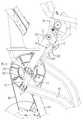
- FIG. 3is a partial right side view of the machine of FIG. 1 .
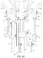
- FIG. 4is a front view of the machine of FIG. 1 .
- FIG. 4Ais an enlarged view of a portion of FIG. 4 .
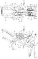
- FIG. 5is a left side view of the machine of FIG. 1 .
- FIG. 5Ais an enlarged view of a portion of FIG. 5 .
- FIG. 6is a top view of the machine of FIG. 1 .
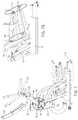
- FIG. 7is a left side view of the machine of FIG. 1 .
- FIG. 7Ais an enlarged view of a portion of FIG. 7 , showing closed loop paths traversed by foot pedals of the machine.
- the disclosed machinesmay provide variable resistance against the reciprocal motion of a user, such as to provide for variable-intensity interval training.
- Some embodimentsmay include reciprocating foot pedals that cause a user's feet to move along a closed loop path that is substantially inclined, such that the foot motion simulates a climbing motion more than a flat walking or running motion.
- Some embodimentsmay include hand members that are configured to move in coordination with the foot pedals and allow the user to exercise upper body muscles. Resistance to the hand members may be proportional to resistance to the foot pedals.
- Variable resistancemay be provided via a rotating air-resistance based fan-like mechanism, via a magnetism based eddy current mechanism, via friction based brakes, and/or via other mechanisms, one or more of which may be rapidly adjusted while the user is using the machine to provide variable intensity interval training.
- FIGS. 1-7Ashow an exemplary embodiment of an exercise machine 10 .
- the machine 10may include a frame 12 , and the frame 12 may include a base 14 for contact with a support surface, a lower support structure 16 extending from the base 14 to an upper support structure 20 , and inclined members 22 that extend between the base 14 and the lower support structure 16 .
- a cross brace 18may connect the inclined members 22 to the lower support structure 16 .
- the various components shown in FIGS. 1-7Aare merely illustrative, and other variations, including eliminating components, combining components, rearranging components, and substituting components are all contemplated.
- the machine 10may include an upper moment-producing mechanism 21 .
- the machinemay also or alternatively include a lower moment-producing mechanism 23 .
- the upper moment-producing mechanism 21 and the lower moment-producing mechanism 23may each provide an input into a crankshaft 25 to rotate the crankshaft 25 about axis A.
- Each mechanism 21 , 23may have a single or multiple separate linkages that produce the moment on the crankshaft 25 .
- the upper moment-producing mechanism 21may include one or more upper linkages extending from the handles 34 to the crankshaft 25 .
- the lower moment-producing mechanism 23may include one or more lower linkages extending from the pedal 32 to the crankshaft 25 .
- the machine 10may include left and right upper linkages, each including a plurality of links configured to connect an input end (e.g., a handle end) of an upper linkage to the crankshaft 25 .
- the machine 10may include left and right lower linkages, each including a plurality of links configured to connect an input end (e.g., a pedal end) of a lower linkage to the crankshaft 25 .
- the crankshaft 25may have a first side and a second side and may be rotatable about the crankshaft axis A. The first side of the crankshaft may be connected, for example, to the left upper and lower linkages, and the second side of the crankshaft may be connected, for example, to the right upper and lower linkages.
- the lower moment-producing mechanism 23may include a first lower linkage and a second lower linkage corresponding to a left and right side of the machine 10 .
- Each of the first and second lower linkagesmay include one or more links operatively arranged to transform a force input from the user (e.g., from the lower body of the user) into a moment about the crankshaft 25 .
- the first and second lower linkagesmay include one or more of first and second pedals 32 , first and second rollers 30 , first and second lower reciprocating members 26 (also referred to as foot members or foot links 26 ), and/or first and second crank arms 28 , respectively.
- the first and second lower linkagesmay operably transmit a force input from the user into a moment about the crankshaft 25 .
- the pedals 32may provide an input into the crankshaft wheel 25 through a lower linkage of the first and second lower reciprocating member 26 and the first and second crank arms 28 .
- the machine 10may include a crank wheel 24 which may be rotatably supported by the frame 12 (for example at the connection of the lower support structure 16 to the upper support structure 20 ) about the crank axis A.
- the first and second crank arms 28may be fixed relative to the crankshaft 25 , which in turn may be fixed relative to the crank wheel 24 .
- the crank arms 28may be positioned on opposite sides of the crank wheel 24 .
- the crank arms 28may be rotatable about the crank axis A, such that rotation of the crank arms 28 causes the crankshaft 25 and the crank wheel 24 to rotate about the crank axis A.
- the first and second crank arms 28may extend from the crankshaft 25 (e.g., from axis A) in opposite radial directions to their respective radial ends.
- first side and the second side of the crankshaft 25may be fixedly connected to the output ends of the first and second crank arms 28 and the input ends of each crank arm 28 may extend radially from the connection between the respective crank arm 28 and the crankshaft 25 .
- First and second lower reciprocating members 26may have forward ends (i.e., output ends) that are pivotally coupled to the radial ends (i.e., input ends) of the first and second crank arms 28 , respectively.
- the rearward ends (i.e., input ends) of the first and second lower reciprocating members 26may be coupled to first and second foot pedals 32 , respectively.
- the rearward ends (i.e., input ends) of the first and second lower reciprocating members 26may thus be interchangeably referred to as pedal ends.
- One or more rollers 30may be coupled to the first and second lower reciprocating members 26 , respectively.
- the one or more rollers 30may be coupled to first and second lower reciprocating members 26 proximate the first and second pedals 32 (for example, the one or more rollers 30 may extend from forward ends of the first and second pedals 32 .
- the first and second pedals 32may be operable for a user to stand on and provide an input force to the first and second lower reciprocating members 26 .
- the rollers 30may rotate on and travel along the inclined members 22 .
- the rollers 30may rollingly translate along the inclined members 22 of the frame 12 to define a travel path for the rollers 30 . Referring to FIG.
- a pair of rollers 30 and an axle 33may be provided for each lower reciprocating member 26 .
- the rollers 30may travel along separate inclined members 22 , which may be spaced apart from one another and coupled together by cross braces 18 , 36 .
- the cross braces 18 , 36may be coupled with opposing ends of the inclined members 22 .
- One cross brace 18may couple upper ends of the inclined members 22 to the lower support structure 16
- the other cross brace 36may couple lower ends of the inclined members 22 to the base 14 .
- a single roller 30is provided for each lower reciprocating member 26 .
- other bearing mechanismsmay be used to provide translational motion of the lower reciprocating members 26 along the inclined members 22 instead of or in addition to the rollers 30 , such as sliding friction-type bearings.
- the pedal ends of the lower reciprocating members 26may translate in a substantially linear path via the rollers 30 along the inclined members 22 .
- the inclined members 22may include a non-linear portion, such as a curved or bowed portion, such that the pedal ends of the lower reciprocating members 26 translate in non-linear path via the rollers 30 along the non-linear portion of the inclined members.
- the non-linear portion of the inclined membersmay have any curvature, such as a curvature of a constant or non-constant radius, and may include convex, concave, and/or partially linear surfaces for the rollers 30 to travel along.
- the non-linear portion of the inclined membersmay have an average angle of inclination of at least 45°, and/or may have a minimum angle of inclination of at least 45°, relative to a horizontal ground plane.
- the forward (i.e., output ends) of the foot members 26may move in circular paths about the crank axis A, which circular motion may drive the crank arms 28 and the crank wheel 24 in a rotational motion about axis A.
- the circular movement of the output ends of the foot members 26may cause the pedals 32 to pivot as the rollers 30 translate along the inclined members 22 .
- the combination of the circular motion of the output ends of the lower reciprocating members 26 , the linear motion of the pedal ends along the inclined member 22 , and the pivotal motion of the pedals 32may cause the pedals 32 to move in non-circular closed loop paths, such as substantially ovular and/or substantially elliptical closed loop paths.
- a point F at the front of the pedals 32may traverse a path 60 and a point R at the rear of the pedals may traverse a path 62 .
- the closed loop paths traversed by different points on the foot pedals 32may have different shapes and sizes, such as with the more rearward portions of the pedals 32 traversing longer distances.
- the path 60may be shorter and/or narrower than the path 62 .
- a closed loop path traversed by the foot pedals 32may have a major axis defined by the two points of the path that are furthest apart.
- the major axis of one or more of the closed loop paths traversed by the pedals 32may have an angle of inclination closer to vertical than to horizontal, such as at least 45°, at least 50°, at least 55°, at least 60°, at least 65°, at least 70°, at least 75°, at least 80°, and/or at least 85°, relative to a horizontal plane defined by the base 14 .
- the inclined members 22may include a substantially linear portion over which the rollers 30 traverse.
- the inclined members 22may form a large angle of inclination a relative to the horizontal base 14 , such as at least 45°, at least 50°, at least 55°, at least 60°, at least 65°, at least 70°, at least 75°, at least 80°, and/or at least 85°.
- This large angle of inclination which sets the path for the foot pedal motionmay provide a user with a lower body exercise more akin to climbing than to walking or running on a level surface.
- Such a lower body exercisemay be similar to that provided by a traditional stair climbing machine.
- the upper moment-producing mechanism 21may include a first upper linkage and a second upper linkage corresponding to a left and right side of machine 10 .
- Each of the first and second upper linkagesmay include one or more links operatively arranged to transform a force input from the user (e.g., from the upper body of the user) into a moment about the crankshaft 25 .
- the first and second upper linkagesmay include one or more of first and second handles 34 , first and second links 38 , first and second upper reciprocating members 40 , and/or first and second intermediate crank arms or links 42 , respectively.
- the first and second upper linkagesmay operatively transmit a force input from the user, at the handles 34 , into a moment about the crankshaft 25 .
- the handles 34may provide an input into the crankshaft 25 through an upper linkage of the first and second links 38 , the first and second reciprocating members 40 , and the first and second intermediate crank arms 42 . Rotation of the crankshaft 25 may cause the upper and lower linkages of the machine 10 to move relative to each other.
- the first and second handles 34may be pivotally coupled to the frame 12 , such as the upper support structure 20 , and may pivot about a horizontal axis D (see FIG. 4A ).
- the machine 10may include first and second handles 35 fixedly coupled to the frame 12 , such as the upper support structure 20 , for a user to grasp with their hands while exercising their legs.
- the handles 34may be rigidly connected to the input end of respective first and second links 38 such that reciprocating pivotal movement of the handles 34 about the horizontal axis D causes corresponding reciprocating pivotal movement of the first and second links 38 about the horizontal axis D.
- the first and second links 38may be cantilevered off of the first and second handles 34 at the pivot aligned with pivot axis D.
- Each of the first and second links 38may form angle ⁇ with the respective handles 34 .
- the angle ⁇may be measured from a plane passing through the axis D and the curve in the handle 34 proximate the connection to the link 38 .
- the angle ⁇may be any angle such as angles between 0 and 180 degrees.
- the angle ⁇may be an angle that is most comfortable to a single user or an average user.
- the first and second links 38may be formed integrally with the first and second handles 34 , respectively.
- the first and second links 38may be referred to as first and second extensions 38 of the first and second handles 34 .
- the first and second links 38may be pivotally coupled at their radial ends (i.e., output ends) to the first and second upper reciprocating members 40 , respectively, to permit relative pivotal motion between the links 38 and the upper reciprocating members 40 .
- the first and second upper reciprocating members 40may be formed as rigid links. With reference to FIG. 4A , upper ends of the upper reciprocating members 40 may be pivotally coupled to the links 38 at axis C. As the handles 34 articulate back and forth (i.e., reciprocate pivotally about axis D), the links 38 move in corresponding arcs about the pivot axis D, which in turn articulates the upper reciprocating members 40 .
- pivot axes Bwhich are defined at the pivot connection of the first and second upper reciprocating members 40 to the first and second intermediate crank arms 42 , respectively, circularly orbit around crank axis A.
- the orbiting axes Bmay be parallel to the fixed crank axis A and offset radially in opposite directions from the fixed crank axis A (see FIGS. 4A and 5A ).
- Each axis Bmay be located proximal to an end of a respective upper reciprocating member 40 and intermediate crank arm 42 .
- the first and second intermediate crank arms 42may be pivotally coupled to the first and second upper reciprocating members 40 , respectively, at axes B, and to the first and second lower reciprocating members 26 , respectively, at axes E.
- the first and second intermediate crank arms 42may be oriented perpendicular to axes B and E.
- the first and second intermediate crank arms 42may be positioned inside of the first and second upper reciprocating members 40 , respectively, and outside of the first and second lower reciprocating members 26 , respectively.
- the first and second lower reciprocating members 26may be positioned outside of the first and second crank arms 28 , respectively.
- first and second intermediate crank arms 42may be fixed relative to the first and second crank arms 28 , respectively, such that respective crank arms 28 , 42 rotate in unison around the crank axis A to rotate the crank wheel 24 and the crankshaft 25 when the pedals 32 and/or the handles 34 are driven by a user.
- respective cranks arms 28 , 42may be fixedly coupled to each other at axes E to define a fixed angle ⁇ between the respective crank arms 28 , 42 .
- the angle ⁇ formed between the respective crank arm 28 and intermediate crank arm 42may be in the range of approximately 0° to 30° (see FIG. 5A ).
- crank axes B and Eorbit about the crank axis A.
- the reciprocating axes B and Emove in circular orbits of different radii about the crank axis A.
- the distance between crank axis A and each axis Bdefines the length of the moment arm of each intermediate crank arm 42 which exerts a moment on the crankshaft 25 , and this moment arm may be considered a virtual crank arm.
- the distance between crank axis A and each axis Edefines the length of the moment arm of each crank arm 28 which exerts a moment on the crankshaft 25 .
- crank axis A and each axis Eis larger than the distance between crank axis A and each axis B, resulting in the crank arms 28 applying a larger moment on the crankshaft 25 than the intermediate crank arms 42 .
- the upper linkage assemblies of the machine 10may be configured in accordance with the examples herein to cause the handles 34 to reciprocate in opposition to the pedals 32 such as to mimic the kinematics of natural human motion. For example, as the left pedal 32 is moving upward and forward, the left handle 34 pivots rearward, and vice versa.
- the machine 10may include a user interface mounted near the top of the upper support member 20 .
- the user interfacemay include a display 43 to provide information to the user, and may include user inputs to allow the user to enter information and to adjust settings of the machine, such as to adjust the resistance.
- the upper moment-producing mechanism 21 of the machine 10may be configured to produce a first mechanical advantage.
- the handles 34pivot about axis D in response to force being exerted against the handles 34 by a user.
- the pivotal motion of the links 38which are fixedly connected to the handles 34 , causes the upper reciprocating members 40 to drive the intermediate crank arms 42 about the crank axis A.
- the intermediate crank arms 42may be pivotally connected to the first and second lower reciprocating members 26 and fixedly connected to the crank arms 28 at axes E, and thus the intermediate crank arms 42 drive the crank arms 28 , which rotate the crankshaft 25 about crank axis A.
- the axes Btravel around the crank axis A in a circular path with the distance between axes B and crank axis A defining the effective moment arm of the intermediate crank arms 42 .
- a virtual crank armmay be defined between axis A and axis B.
- FIGS. 2A-2Dshow the intermediate crank arms 42 in different positions around the crank axis A.
- the different positions of the intermediate crank arms 42represent rotation of the crankshaft 25 which is fixedly attached to the intermediate crank arms 42 through the crank arms 28 . Due to the fixed attachment, the intermediate crank arms 42 transmit a force received from the first and second handles 34 to the crankshaft 25 .
- the intermediate crank arms 42may be fixedly positioned relative to the crank arms 28 .
- the intermediate crank arms 42may be set at a fixed angle ⁇ relative to the crank arms 28 .
- the angle ⁇may be any angle (i.e., 0-360 degrees). In some examples, the angle ⁇ may be between 0° and 30° (see FIG. 5A ). In one example, the angle ⁇ may be 15°.
- the upper moment-producing mechanism 21 of the machine 10may be configured to produce a second mechanical advantage.
- the pedals 32pivot around the rollers 30 in response to force being exerted against the first and second lower reciprocating members 26 through the pedals 32 .
- the force on the first and second lower reciprocating members 26drives the first and second crank arms 28 , respectively.
- the crank arms 28are pivotally connected at axes E to the first and second lower reciprocating members 26 and fixedly connected to the crankshaft 25 at axis A.
- the force exerted on the pedals 32drives the crank arms 28 , which rotate the crankshaft 25 about axis A.
- crank arms 28in different positions around the crank axis A.
- the different positions of the crank arms 28represent rotation of the crankshaft 25 which is fixedly attached to the crank arms 28 . Due to the fixed attachment, the crank arms 28 transmit a force received from the first and second lower reciprocating members 26 to the crankshaft 25 .
- the mechanical advantage of the upper and lower moment-producing linkages or mechanisms 21 , 23may be manipulated by altering the characteristics of the various elements.
- the leverage applied by the handles 34may be established by length of the handles or the location from which the handles 34 receive the input from the user.
- the leverage applied by the first and second links 38may be established by the distance from axis D to axis C.
- the leverage applied by the intermediate crank arms 42may be established by the distance between axis B and axis A.
- the upper reciprocating members 40may connect the first and second links 38 to the intermediate crank arms 42 over the distance from axis C to axis B.
- the ratio of the distance between axes D and C compared to the distance between axes B and Amay be, in one example, between 1:4 and 4:1. In another example, the ratio may be between 1:1 and 4:1. In another example, the ratio may be between 2:1 and 3:1. In another example, the ratio may be about 2.8:1. Similar ratios may apply to the ratio of axis B to axis A compared to axis A to axis E (i.e., B-A:A-E).
- the upper moment-producing mechanism 21 and the lower moment-producing mechanism 23functioning together or separately, transmit input by the user at the handles 34 and/or the pedals 32 to a rotational movement of the crankshaft 25 .
- the upper moment-producing mechanism 21drives the crankshaft 25 with a first mechanical advantage (e.g., as a comparison of the input force to the moment at the crankshaft).
- the first mechanical advantagemay vary throughout the cycling of the handles 34 .
- the mechanical advantage supplied by the upper moment-producing mechanism 21 to the crankshaft 25may change with the progression of the cycle of the machine.
- the lower moment-producing mechanism 23drives the crankshaft 25 with a second mechanical advantage (e.g., as a comparison of the input force at the pedals 32 to the torque at the crankshaft 25 at a particular instant or angle).
- the second mechanical advantagemay vary throughout the cycle of the pedals 32 as defined by the vertical position of the rollers 30 relative to their top vertical and bottom vertical position. For example, as the pedals 32 change position, the mechanical advantage supplied by the lower moment-producing mechanism 23 may change with the changing position of the pedals 32 .
- each of the moment-producing mechanisms 21 , 23may have a mechanical advantage profile that describes the mechanical effect across the entire cycle of the handles 34 and/or pedals 32 .
- the first mechanical advantage profilemay be different than the second mechanical advantage profile at any instance in the cycle and/or the profiles may generally be different across the entire cycle.
- the exercise machine 10may be configured to balance the user's upper body workout (e.g. at the handles 34 ) by utilizing the first mechanical advantage differently as compared to the user's lower body workout (e.g. at the pedals 32 ) utilizing the second mechanical advantage.
- the upper moment-producing mechanism 21may substantially match the lower moment-producing mechanism 23 at such points where the respective mechanical advantage profiles are near their respective maximums. Regardless of difference or similarities in respective mechanical advantage profiles throughout the cycling of the exercise machine, the inputs to the handles 34 and pedals 32 still work in concert through their respective mechanisms to drive the crankshaft 25 .
- the exercise machine 10may include a resistance mechanism operatively arranged to resist the rotation of the crankshaft 25 .
- the exercise machine 10may include one or more resistance mechanism such as an air-resistance based resistance mechanism, a magnetism based resistance mechanism, a friction based resistance mechanism, and/or other resistance mechanisms.
- the crank wheel 24may be coupled to one or more resistance mechanisms to provide resistance to the reciprocating motion of the pedals 32 and handles 34 .
- resistancemay be applied via an air brake, a friction brake, a magnetic brake, or the like.
- the machine 10may include an air-resistance based resistance mechanism, such as air brake 54 , rotationally coupled to the frame 12 .
- the machine 10may additionally or alternatively include a magnetic-resistance based resistance mechanism, or magnetic brake 53 (see e.g., FIG. 1-4 ).
- the rotor 50 and the air brake 54may be driven by rotation of the crankshaft 25 and each may be operable to resist the rotation of the crankshaft 25 .
- the rotor 50 and the air brake 54are driven by a belt or chain 44 that is routed around the crank wheel 24 and a pulley 46 (see, e.g., FIG. 3 ).
- the ratio of the diameters of the crank wheel 24 and the pulley 46may be used as a gearing mechanism to adjust the ratio of the angular velocity of the rotor 50 and the air brake 54 to the angular velocity of the crank wheel 24 .
- one rotation of the crank wheel 24may cause several rotations of the rotor and/or the air brake 54 to increase the resistance provided by the resistance mechanism.
- a tensioner or idler systemmay be used to take up extra slack in the belt or chain 44 and to increase the wrap angle of the belt or chain 44 about the crank wheel 24 and/or the pulley 46 .
- One or more of the resistance mechanismscan be adjustable to provide different levels of resistance at a given reciprocation frequency. Further, one or more of the resistance mechanisms can provide a variable resistance that corresponds to the reciprocation frequency of the exercise machine, such that resistance increases as reciprocation frequency increases. For example, one reciprocation of the pedals 32 and/or handles 34 may cause several rotations of the rotor 50 and/or air brake 54 to increase the resistance provided by the magnetic brake 53 and/or air brake 54 .
- the air brake 54may be adjustable to control the volume of air flow that is induced to flow through the air brake at a given angular velocity in order to vary the resistance provided by the air brake.
- the air brake 54may include a radial fin structure that causes air to flow through the air brake when it rotates. For example, rotation of the air brake 54 may cause air to enter through lateral openings on the lateral side of the air brake near the rotation axis and exit through radial outlets opening to a radial perimeter of the air brake.
- the induced air motion through the air brake 54may cause resistance to the rotation of the crank wheel 24 and thus crankshaft 25 , which is transferred to resistance to the reciprocating motions of the pedals 32 and handles 34 .
- the resistance forcemay increase in a non-linear relationship, such as a substantially exponential relationship.
- an air brakemay include an inlet plate that is adjustable in an axial direction (and optionally also in a rotational direction).
- An axially adjustable inlet platemay be configured to move in a direction parallel to the rotation axis of the air brake. For example, when the inlet plate is further away axially from the air inlet(s), increased air flow volume is permitted, and when the inlet plate is closer axially to the air inlet(s), decreased air flow volume is permitted.
- an air brakemay include an air outlet regulation mechanism that is configured to change the total cross-flow area of the air outlets at the radial perimeter of the air brake, in order to adjust the air flow volume induced through the air brake at a given angular velocity.
- the air brake 54may include an adjustable air flow regulation mechanism, such as the inlet plate or other mechanism described herein, that can be adjusted rapidly while the machine 10 is being used for exercise.
- the air brake 54may include an adjustable air flow regulation mechanism that can be rapidly adjusted by the user while the user is driving the rotation of the air brake, such as by manipulating a manual lever, a button, or other mechanism positioned within reach of the user's hands while the user is driving the pedals 32 with the user's feet.
- Such a mechanismmay be mechanically and/or electrically coupled to the air flow regulation mechanism to cause an adjustment of air flow and thus adjust the resistance level.
- such a user-caused adjustmentmay be automated, such as using a button or mechanism 57 on a console near the handles 34 coupled to a controller and an electrical motor coupled to the air flow regulation mechanism.
- such an adjustment mechanismmay be entirely manually operated, or a combination of manual and automated.
- a usermay cause a desired air flow regulation adjustment to be fully enacted in a relatively short time frame, such as within a fraction of a second or multiple seconds.
- the magnetic brake 53may include the rotor 50 rotationally coupled to the frame 12 and a brake caliper 55 coupled to the frame 12 .
- the magnetic brake 53may provide resistance to rotation of the crankshaft 25 by magnetically inducing eddy currents in the rotor 50 as the rotor rotates.
- the brake caliper 55may include magnets positioned on opposite sides of the rotor 50 . As the rotor 50 rotates between the magnets, the magnetic fields created by the magnets induce eddy currents in the rotor 50 , producing resistance to the rotation of the rotor 50 . To adjust resistance, the magnitude of the magnetic field may be varied (e.g., increased or decreased) to an outer portion of the rotor 50 .
- the magnitude of the resistance to rotation of the rotor 50may increase as a function of the angular velocity of the rotor 50 , such that higher resistance is provided at high reciprocation frequencies of the pedals 32 and handles 34 .
- the magnitude of resistance provided by the magnetic brake 53may also be a function of the radial distance from the magnets to the rotation axis of the rotor 50 . As this radius increases, the linear velocity of the portion of the rotor 50 passing between the magnets increases at any given angular velocity of the rotor 50 , as the linear velocity at a point on the rotor 50 is a product of the angular velocity of the rotor 50 and the radius of that point from the rotation axis.
- the brake caliper 55may be pivotally mounted, or otherwise adjustably mounted, to the frame 12 such that the radial position of the magnets relative to the rotation axis of the rotor 50 may be adjusted to move the magnets to different radial positions relative to the rotor 50 to change the resistance provided by the magnetic brake 53 at a given reciprocation frequency of the pedals 32 and handles 34 .
- the brake caliper 55may be adjusted rapidly while the machine 10 is being used for exercise to adjust the resistance.
- the radial position of the magnets of the brake caliper 55 relative to the rotor 50may be rapidly adjusted by the user while the user is driving the reciprocation of the pedals 32 and/or handles 34 , such as by manipulating a lever 57 , a button, or other mechanism positioned within reach of the user's hands (see e.g., FIG. 1 ) while the user is driving the pedals 32 with the user's feet.
- Such an adjustment mechanismmay be mechanically and/or electrically coupled to the magnetic brake 53 to cause an adjustment of eddy currents in the rotor 50 and thus adjust the magnetic resistance level.
- the user interface 43may include a display to provide information to the user, and may include user inputs to allow the user to enter to adjust settings of the machine, such as to adjust the resistance.
- a user-caused adjustmentcan be automated, such as using a button on the user interface 43 that is electrically coupled to a controller and an electrical motor coupled to the brake caliper 53 .
- such an adjustment mechanismmay be entirely manually operated, or a combination of manual and automated.
- a usermay cause a desired magnetic resistance adjustment to be fully enacted in a relatively short time frame, such as within a half-second, within one second, within two seconds, within three second, within four seconds, and/or within five seconds from the time of manual input by the user via an electronic input device or manual actuation of a mechanical device.
- the magnetic resistance adjustment time periodscan be smaller or greater than the time periods provided above.
- the exercise machine 10 shown in FIGS. 1-7Amay include an outer housing (not shown) positioned around a front portion of the machine.
- the housingmay house and protect portions of the frame 12 , the pulley 46 , the belt or chain 44 , lower portions of the upper reciprocating members 40 , the air brake 54 , the magnetic brake 53 , motors for adjusting the air brake and/or magnetic brake, wiring, and/or other components of the machine 10 .
- the housingmay include an air brake enclosure that includes lateral inlet openings to allow air into the air brake 54 and radial outlet openings to allow air out of the air brake.
- the housingmay include a magnetic brake enclosure to protect the magnetic brake 53 , where the magnetic brake is included in addition to or instead of the air brake 54 .
- the crank wheel 24 , crank arms 28 , and/or intermediate crank arms 42may be exposed through the housing such that the upper and lower reciprocating members 40 , 26 can drive the respective components in a circular motion about the axis A without obstruction by the housing.
- Embodiments that include a variable resistance mechanism that provide increased resistance at higher angular velocity and a rapid resistance mechanism that allow a user to quickly change the resistance at a given angular velocityallow the machine 10 to be used for high intensity interval training.
- a usercan perform repeated intervals alternating between high intensity periods and low intensity periods.
- High intensity periodscan be performed with the adjustable resistance mechanism, such as the magnetic braking system 53 and/or the air brake 54 , set to a low resistance setting (e.g., with the inlet plate blocking air flow through the air brake 54 ).
- the usercan drive the pedals 32 and/or handles 34 at a relatively high reciprocation frequency, which can cause increased energy exertion because, even though there is reduced resistance from the air brake 54 , the user is caused to lift and lower his own body weight a significant distance for each reciprocation, like with a traditional stair climber machine.
- the rapid climbing motioncan lead to an intense energy exertion.
- Such a high intensity periodcan last any length of time, such as less than one minute, or less than 30 seconds, while providing sufficient energy exertion as the user desires.
- Low intensity periodscan be performed with the adjustable resistance mechanism, such as the magnetic braking system 53 and/or the air brake 54 , set to a high resistance setting (e.g., with the inlet plate allowing maximum air flow through the air brake 54 ).
- a high resistance settinge.g., with the inlet plate allowing maximum air flow through the air brake 54 .
- the relatively slower climbing motioncan provide a rest period between high intensity periods.
- Such a low intensity period or rest periodcan last any length of time, such as less than two minutes, or less than about 90 seconds.
- An exemplary interval training sessioncan include any number of high intensity and low intensity periods, such less than 10 of each and/or less than about 20 minutes total, while providing a total energy exertion that requires significantly longer exercise time, or is not possible, on a traditional stair climber or a traditional elliptical machine.
- the terms “a”, “an” and “at least one”encompass one or more of the specified element. That is, if two of a particular element are present, one of these elements is also present and thus “an” element is present.
- the terms “a plurality of” and “plural”mean two or more of the specified element.
- the term “and/or” used between the last two of a list of elementsmeans any one or more of the listed elements.
- the phrase “A, B, and/or C”means “A,” “B,” “C,” “A and B,” “A and C,” “B and C” or “A, B and C.”
Landscapes
- Health & Medical Sciences (AREA)
- General Health & Medical Sciences (AREA)
- Physical Education & Sports Medicine (AREA)
- Cardiology (AREA)
- Vascular Medicine (AREA)
- Orthopedic Medicine & Surgery (AREA)
- Life Sciences & Earth Sciences (AREA)
- Biophysics (AREA)
- Physics & Mathematics (AREA)
- Electromagnetism (AREA)
- Human Computer Interaction (AREA)
- Engineering & Computer Science (AREA)
- Rehabilitation Tools (AREA)
- Transmission Devices (AREA)
Abstract
Description
Claims (20)
Priority Applications (5)
| Application Number | Priority Date | Filing Date | Title |
|---|---|---|---|
| US15/606,754US10561891B2 (en) | 2017-05-26 | 2017-05-26 | Exercise machine |
| EP18731642.7AEP3630306B1 (en) | 2017-05-26 | 2018-05-22 | Exercise machine |
| CN201880046523.6ACN111182947B (en) | 2017-05-26 | 2018-05-22 | fitness equipment |
| PCT/US2018/033925WO2018217776A1 (en) | 2017-05-26 | 2018-05-22 | Exercise machine |
| TW107117768ATWI755539B (en) | 2017-05-26 | 2018-05-24 | Exercise machine |
Applications Claiming Priority (1)
| Application Number | Priority Date | Filing Date | Title |
|---|---|---|---|
| US15/606,754US10561891B2 (en) | 2017-05-26 | 2017-05-26 | Exercise machine |
Publications (2)
| Publication Number | Publication Date |
|---|---|
| US20180339189A1 US20180339189A1 (en) | 2018-11-29 |
| US10561891B2true US10561891B2 (en) | 2020-02-18 |
Family
ID=62621015
Family Applications (1)
| Application Number | Title | Priority Date | Filing Date |
|---|---|---|---|
| US15/606,754Active2037-12-15US10561891B2 (en) | 2017-05-26 | 2017-05-26 | Exercise machine |
Country Status (5)
| Country | Link |
|---|---|
| US (1) | US10561891B2 (en) |
| EP (1) | EP3630306B1 (en) |
| CN (1) | CN111182947B (en) |
| TW (1) | TWI755539B (en) |
| WO (1) | WO2018217776A1 (en) |
Cited By (4)
| Publication number | Priority date | Publication date | Assignee | Title |
|---|---|---|---|---|
| US11324994B2 (en) | 2013-03-15 | 2022-05-10 | Nautilus, Inc. | Exercise machine |
| US11484749B2 (en) | 2018-07-23 | 2022-11-01 | Life Fitness, Llc | Exercise machines having adjustable elliptical striding motion |
| US12011638B2 (en) | 2020-03-09 | 2024-06-18 | Life Fitness, Llc | Exercise machines for facilitating elliptical striding motion |
| US20250235738A1 (en)* | 2024-01-19 | 2025-07-24 | Oma Fitness Equipment Co.,Ltd. | Elliptical machine |
Families Citing this family (7)
| Publication number | Priority date | Publication date | Assignee | Title |
|---|---|---|---|---|
| AU2014232303B2 (en) | 2013-03-15 | 2017-02-23 | Johnson Health Tech Retail, Inc. | Exercise machine |
| TWI621463B (en)* | 2017-03-16 | 2018-04-21 | 力伽實業股份有限公司 | Arm and leg compound exercise maching |
| TWI668034B (en)* | 2018-12-12 | 2019-08-11 | 岱宇國際股份有限公司 | Sports equipment |
| US11103740B2 (en) | 2019-03-08 | 2021-08-31 | Nautilus, Inc. | Foot supports with fit enhancement features for an exercise machine |
| TWI707711B (en)* | 2019-12-17 | 2020-10-21 | 清河國際股份有限公司 | Link mechanism of elliptical motion track |
| USD1031875S1 (en)* | 2024-01-12 | 2024-06-18 | Xiamen Weldconn Technology Co., Ltd. | Elliptical machine |
| USD1031874S1 (en)* | 2024-02-06 | 2024-06-18 | Xiamen Weldconn Technology Co., Ltd. | Elliptical machine |
Citations (104)
| Publication number | Priority date | Publication date | Assignee | Title |
|---|---|---|---|---|
| US1219439A (en) | 1915-10-01 | 1917-03-20 | Union Mfg Co | Machine-chuck. |
| US3134378A (en) | 1960-10-10 | 1964-05-26 | Richard J Harwood | Exercise machine |
| US3213852A (en) | 1963-07-29 | 1965-10-26 | Lawson J Zent | Exercising apparatus |
| US3964742A (en) | 1973-10-17 | 1976-06-22 | Guido Carnielli | Physiological active and passive exercising apparatus |
| EP0323056A2 (en) | 1987-12-29 | 1989-07-05 | Cateye Co., Ltd. | Cycle trainer having a load applying device |
| US4880225A (en) | 1988-07-28 | 1989-11-14 | Diversified Products Corporation | Dual action cycle exerciser |
| US5048824A (en) | 1990-07-11 | 1991-09-17 | Ya Te Industry Co., Ltd. | Air resistance excerciser with negative ion generator |
| US5051638A (en) | 1989-12-19 | 1991-09-24 | Nathan Pyles | Magnetically variable air resistance wheel for exercise devices |
| US5242343A (en) | 1992-09-30 | 1993-09-07 | Larry Miller | Stationary exercise device |
| US5290211A (en) | 1992-10-29 | 1994-03-01 | Stearns Technologies, Inc. | Exercise device |
| US5290212A (en) | 1991-09-03 | 1994-03-01 | Roadmaster Corporation | Exercise cycle |
| US5499956A (en) | 1992-12-01 | 1996-03-19 | Nordictrack, Inc. | Articulated lower body exerciser |
| US5518473A (en) | 1995-03-20 | 1996-05-21 | Miller; Larry | Exercise device |
| US5529555A (en) | 1995-06-06 | 1996-06-25 | Ccs, Llc | Crank assembly for an exercising device |
| US5540637A (en) | 1995-01-25 | 1996-07-30 | Ccs, Llc | Stationary exercise apparatus having a preferred foot platform orientation |
| US5549526A (en) | 1995-01-25 | 1996-08-27 | Ccs, Llc | Stationary exercise apparatus |
| US5562574A (en) | 1996-02-08 | 1996-10-08 | Miller; Larry | Compact exercise device |
| US5573480A (en) | 1995-01-25 | 1996-11-12 | Ccs, Llc | Stationary exercise apparatus |
| US5577985A (en) | 1996-02-08 | 1996-11-26 | Miller; Larry | Stationary exercise device |
| US5593372A (en) | 1995-01-25 | 1997-01-14 | Ccs, Llc | Stationary exercise apparatus having a preferred foot platform path |
| US5595553A (en) | 1995-01-25 | 1997-01-21 | Ccs, Llc | Stationary exercise apparatus |
| US5611758A (en) | 1996-05-15 | 1997-03-18 | Ccs, Llc | Recumbent exercise apparatus |
| US5653662A (en) | 1996-05-24 | 1997-08-05 | Rodgers, Jr.; Robert E. | Stationary exercise apparatus |
| US5683330A (en) | 1995-12-11 | 1997-11-04 | The University Of Tokyo | Sprint training machine |
| US5685804A (en) | 1995-12-07 | 1997-11-11 | Precor Incorporated | Stationary exercise device |
| US5690589A (en) | 1995-01-25 | 1997-11-25 | Rodgers, Jr.; Robert E. | Stationary exercise apparatus |
| US5707321A (en) | 1995-06-30 | 1998-01-13 | Maresh; Joseph Douglas | Four bar exercise machine |
| US5738614A (en) | 1995-01-25 | 1998-04-14 | Rodgers, Jr.; Robert E. | Stationary exercise apparatus with retractable arm members |
| US5743834A (en) | 1995-01-25 | 1998-04-28 | Rodgers, Jr.; Robert E. | Stationary exercise apparatus with adjustable crank |
| US5795270A (en) | 1996-03-21 | 1998-08-18 | Jim Woods | Semi-recumbent arm and leg press exercising apparatus |
| US5836855A (en) | 1997-02-18 | 1998-11-17 | Eschenbach; Paul William | Recumbent elliptical exercise machine |
| US5997445A (en) | 1997-08-19 | 1999-12-07 | Maresh; Joseph D. | Elliptical exercise methods and apparatus |
| US6019710A (en) | 1998-01-06 | 2000-02-01 | Icon Health & Fitness, Inc. | Exercising device with elliptical movement |
| US6024676A (en) | 1997-06-09 | 2000-02-15 | Eschenbach; Paul William | Compact cross trainer exercise apparatus |
| US6206806B1 (en) | 2000-03-31 | 2001-03-27 | Yong S. Chu | Elliptical motion exerciser |
| US6422977B1 (en) | 1997-06-09 | 2002-07-23 | Paul William Eschenbach | Compact elliptical exercise machine with adjustment |
| US20030096677A1 (en) | 2001-11-20 | 2003-05-22 | Inray Fitness Products Corp. | Oval orbit exercise bike |
| US20050181911A1 (en) | 2004-02-18 | 2005-08-18 | Porth Timothy J. | Exercise equipment with automatic adjustment of stride length and/or stride height based upon speed of foot support |
| US20050181912A1 (en)* | 2002-11-26 | 2005-08-18 | Eschenbach Paul W. | Elliptical exercise apparatus with adjustable crank |
| USD512112S1 (en) | 2003-11-28 | 2005-11-29 | Cateye Co., Ltd. | Exercising machine |
| US20060079381A1 (en) | 2004-07-30 | 2006-04-13 | Cornejo Victor T | Articulating linkage exercise machine |
| US20060166791A1 (en) | 2005-01-21 | 2006-07-27 | Hung-Mao Liao | Elliptical exercise machine with adjustable elliptical path |
| US20060172865A1 (en) | 2004-07-30 | 2006-08-03 | James Dey | Linkage based exercise machine |
| US7086993B1 (en) | 1995-06-30 | 2006-08-08 | Maresh Joseph D | Exercise methods and apparatus |
| US20060293153A1 (en) | 2005-06-28 | 2006-12-28 | Porth Timothy J | Exercise equipment with convergent hand grips |
| US7201705B2 (en) | 2003-06-06 | 2007-04-10 | Rodgers Jr Robert E | Exercise apparatus with a variable stride system |
| US20070087906A1 (en)* | 2003-06-06 | 2007-04-19 | Rodgers Robert E Jr | Variable stride exercise apparatus |
| US20070117683A1 (en) | 2005-11-22 | 2007-05-24 | Icon Health & Fitness, Inc. | Exercising apparatus with varying length arms |
| US20070129219A1 (en) | 2005-12-01 | 2007-06-07 | Robert Mahlberg | Exercise device |
| US7238146B1 (en) | 2006-07-25 | 2007-07-03 | James Chen | Elliptical exercise apparatus |
| US20070232457A1 (en)* | 2004-01-23 | 2007-10-04 | Porth Timothy J | Exercise Equipment With Automatic Adjustment Of Stride Length And/Or Stride Height Based Upon Direction Of Foot Support Rotation |
| US20070254778A1 (en) | 2006-04-14 | 2007-11-01 | Ashby Darren C | Exercise apparatuses, components for exercise apparatuses and related methods |
| USD559925S1 (en) | 2006-12-28 | 2008-01-15 | Precor Incorporated | Exercise device |
| USD565129S1 (en) | 2007-01-16 | 2008-03-25 | Johnson Health Tech. Co., Ltd. | Exercise apparatus |
| USD567310S1 (en) | 2007-01-16 | 2008-04-22 | Johnson Health Tech Co., Ltd. | Exercise apparatus |
| USD567314S1 (en) | 2006-12-28 | 2008-04-22 | Precor Incorporated | Shroud for an exercise device |
| US7377879B1 (en) | 2007-02-14 | 2008-05-27 | Michael Lin | Pedal adjustable system for exercisers |
| US20080161163A1 (en) | 2006-12-28 | 2008-07-03 | Precor Incorporated | Supplemental resistance assembly for resisting motion of an exercise device |
| USD575363S1 (en) | 2006-12-28 | 2008-08-19 | Precor Incorporated | Foot pad for an exercise device |
| US20080207400A1 (en) | 2007-02-23 | 2008-08-28 | Shu-Chiung Liao Lai | Low-impact exercise machine |
| US20080220947A1 (en) | 2003-08-08 | 2008-09-11 | Jie Meng | Multi-Functional Fitness Bicycle |
| US7448986B1 (en) | 2004-02-18 | 2008-11-11 | Octane Fitness, Llc | Exercise equipment with automatic adjustment of stride length and/or stride height based upon the heart rate of a person exercising on the exercise equipment |
| US20080280731A1 (en) | 2007-05-08 | 2008-11-13 | Icon Health & Fitness, Inc. | Elliptical exercise machine with adjustable foot motion |
| US7462134B2 (en) | 2003-06-23 | 2008-12-09 | Nautilus, Inc. | Variable stride exercise device |
| US20090011904A1 (en) | 2007-07-06 | 2009-01-08 | Jin Chen Chuang | Elliptical exercise device |
| US20090048077A1 (en)* | 2007-08-14 | 2009-02-19 | Jin Chen Chuang | Stationary exerciser |
| WO2009026604A2 (en) | 2007-08-30 | 2009-03-05 | Wilson, Ian, John | Ergometric training device |
| US20090093346A1 (en) | 2007-10-08 | 2009-04-09 | Johnson Health Tech Co., Ltd. | Cross trainer exercise apparatus |
| US20090124463A1 (en) | 2007-11-08 | 2009-05-14 | Michael Lin | Exerciser having adjustable moving stroke |
| US7556591B2 (en) | 2007-04-17 | 2009-07-07 | Jin Chen Chuang | Stationary exercise device |
| US20090203501A1 (en) | 2007-05-10 | 2009-08-13 | Rodgers Jr Robert E | Adjustable Geometry Exercise Devices and Methods for Use Thereof |
| US7591761B1 (en) | 2006-04-27 | 2009-09-22 | Northland Industries | Walking/jogging exercise machine with articulated cam follower arrangement |
| US7611446B2 (en) | 2007-04-17 | 2009-11-03 | Jin Chen Chuang | Adjustable exercise device |
| US7618350B2 (en) | 2007-06-04 | 2009-11-17 | Icon Ip, Inc. | Elliptical exercise machine with adjustable ramp |
| US20090312156A1 (en) | 2008-06-11 | 2009-12-17 | Michael Lin | Adjustable elliptical exercise machine |
| USD606599S1 (en) | 2009-04-15 | 2009-12-22 | Michael Lin | Exerciser |
| US7666122B2 (en) | 2005-07-18 | 2010-02-23 | Unisen, Inc. | Elliptical exercise machine |
| US7736278B2 (en) | 2003-06-23 | 2010-06-15 | Nautilus, Inc. | Releasable connection mechanism for variable stride exercise devices |
| US20100167877A1 (en) | 2008-12-29 | 2010-07-01 | Precor Incorporated | Adaptive motion exercise device with oscillating track |
| US20100190613A1 (en) | 2009-01-27 | 2010-07-29 | Michael Lin | Coaxial load wheel and cranks |
| US7785235B2 (en) | 2003-06-23 | 2010-08-31 | Nautilus, Inc. | Variable stride exercise device |
| US7789808B2 (en) | 2008-07-30 | 2010-09-07 | Sunny Lee | Exercising device |
| US20100234185A1 (en) | 2009-03-13 | 2010-09-16 | Nautilus, Inc. | Exercise bike |
| EP2383020A1 (en) | 2010-04-27 | 2011-11-02 | Tonic Fitness Technology , Inc. | Elliptical trainer for arms |
| US20120088635A1 (en) | 2010-10-08 | 2012-04-12 | Superweigh Enterprise Co., Ltd. | Elliptical Exercise Apparatus |
| US20130012363A1 (en) | 2010-05-05 | 2013-01-10 | Paul William Eschenbach | Selective stride elliptical exercise apparatus |
| US20130085042A1 (en) | 2011-09-30 | 2013-04-04 | Hsuan-Fu HUANG | Pedal correction mechanism for elliptical trainer |
| US20130237379A1 (en) | 2012-03-06 | 2013-09-12 | Hsuan-Fu HUANG | Pedal lifting mechanism for elliptical trainer |
| USD703278S1 (en) | 2012-02-28 | 2014-04-22 | Precor Incorporated | Exercise device |
| US8734298B2 (en) | 2011-01-24 | 2014-05-27 | Dyaco International, Inc. | Adjustable exercise machine |
| US20140194253A1 (en) | 2013-01-07 | 2014-07-10 | Dyaco International Inc. | Pedal motion path adjustable elliptical trainer |
| US20140248998A1 (en) | 2013-03-04 | 2014-09-04 | Brunswick Corporation | Exercise assemblies having foot pedal members that are movable along user defined paths |
| WO2014145981A1 (en) | 2013-03-15 | 2014-09-18 | Yim Ramsey | Exercise machine |
| US20140274575A1 (en) | 2013-03-15 | 2014-09-18 | Nautilus, Inc. | Exercise machine |
| US8926478B2 (en) | 2013-02-04 | 2015-01-06 | Dyaco International Inc. | Elliptical trainer |
| US8979713B2 (en) | 2013-01-07 | 2015-03-17 | Dyaco International Inc. | Pedal motion path adjustable elliptical trainer |
| US9056217B2 (en) | 2012-03-06 | 2015-06-16 | Dyaco International Inc. | Stationary exercise apparatus |
| US9061174B2 (en) | 2010-07-23 | 2015-06-23 | Woo Sick Jun | Bike saddle structure having adjustable oscillation angle and height |
| US20150238809A1 (en) | 2014-02-26 | 2015-08-27 | Dyaco International Inc. | Exercise device providing adjustable step distance |
| US20160008658A1 (en) | 2013-03-15 | 2016-01-14 | Nautilus, Inc. | Exercise machine |
| US9254414B2 (en) | 2013-09-24 | 2016-02-09 | Dyaco International Inc. | Exercise device |
| US9468797B1 (en) | 2016-03-30 | 2016-10-18 | Larry D. Miller Trust | Exercise device with elliptical stepping motion |
| US20170056709A1 (en) | 2015-08-28 | 2017-03-02 | Icon Health & Fitness, Inc. | Pedal Path of a Stepping Machine |
| US20170056717A1 (en) | 2015-08-28 | 2017-03-02 | Icon Health & Fitness, Inc. | Pedal Path of a Stepping Machine |
Family Cites Families (9)
| Publication number | Priority date | Publication date | Assignee | Title |
|---|---|---|---|---|
| US6689019B2 (en)* | 2001-03-30 | 2004-02-10 | Nautilus, Inc. | Exercise machine |
| US8562491B2 (en)* | 2007-09-13 | 2013-10-22 | Flatiron Design, Llc | Seated exercise apparatus |
| CN101417170B (en)* | 2007-10-24 | 2012-04-25 | 庄进成 | elliptical machine |
| AT507828B1 (en)* | 2009-01-19 | 2011-04-15 | Tyrolia Technology Gmbh | ski binding |
| US8992364B2 (en)* | 2012-02-04 | 2015-03-31 | Icon Health & Fitness, Inc. | Direct drive for exercise machines |
| CN105080050B (en)* | 2014-05-22 | 2018-01-19 | 岱宇国际股份有限公司 | Elliptical trainer |
| CN203886109U (en)* | 2014-05-22 | 2014-10-22 | 岱宇国际股份有限公司 | elliptical machine |
| CN204261262U (en)* | 2014-12-02 | 2015-04-15 | 陈仪慈 | elliptical machine |
| CN106422176B (en)* | 2015-08-07 | 2018-11-30 | 力山工业股份有限公司 | Elliptical machine capable of limiting operation stroke |
- 2017
- 2017-05-26USUS15/606,754patent/US10561891B2/enactiveActive
- 2018
- 2018-05-22CNCN201880046523.6Apatent/CN111182947B/enactiveActive
- 2018-05-22EPEP18731642.7Apatent/EP3630306B1/enactiveActive
- 2018-05-22WOPCT/US2018/033925patent/WO2018217776A1/ennot_activeCeased
- 2018-05-24TWTW107117768Apatent/TWI755539B/enactive
Patent Citations (114)
| Publication number | Priority date | Publication date | Assignee | Title |
|---|---|---|---|---|
| US1219439A (en) | 1915-10-01 | 1917-03-20 | Union Mfg Co | Machine-chuck. |
| US3134378A (en) | 1960-10-10 | 1964-05-26 | Richard J Harwood | Exercise machine |
| US3213852A (en) | 1963-07-29 | 1965-10-26 | Lawson J Zent | Exercising apparatus |
| US3964742A (en) | 1973-10-17 | 1976-06-22 | Guido Carnielli | Physiological active and passive exercising apparatus |
| EP0323056A2 (en) | 1987-12-29 | 1989-07-05 | Cateye Co., Ltd. | Cycle trainer having a load applying device |
| US4880225A (en) | 1988-07-28 | 1989-11-14 | Diversified Products Corporation | Dual action cycle exerciser |
| US5051638A (en) | 1989-12-19 | 1991-09-24 | Nathan Pyles | Magnetically variable air resistance wheel for exercise devices |
| US5048824A (en) | 1990-07-11 | 1991-09-17 | Ya Te Industry Co., Ltd. | Air resistance excerciser with negative ion generator |
| US5290212A (en) | 1991-09-03 | 1994-03-01 | Roadmaster Corporation | Exercise cycle |
| US5242343A (en) | 1992-09-30 | 1993-09-07 | Larry Miller | Stationary exercise device |
| US5383829A (en) | 1992-09-30 | 1995-01-24 | Miller; Larry | Stationary exercise device |
| US5383829C1 (en) | 1992-09-30 | 2002-03-05 | Larry Miller | Stationary exercise device |
| US5290211A (en) | 1992-10-29 | 1994-03-01 | Stearns Technologies, Inc. | Exercise device |
| US5499956A (en) | 1992-12-01 | 1996-03-19 | Nordictrack, Inc. | Articulated lower body exerciser |
| US5549526A (en) | 1995-01-25 | 1996-08-27 | Ccs, Llc | Stationary exercise apparatus |
| US5593372A (en) | 1995-01-25 | 1997-01-14 | Ccs, Llc | Stationary exercise apparatus having a preferred foot platform path |
| US5690589A (en) | 1995-01-25 | 1997-11-25 | Rodgers, Jr.; Robert E. | Stationary exercise apparatus |
| US5743834A (en) | 1995-01-25 | 1998-04-28 | Rodgers, Jr.; Robert E. | Stationary exercise apparatus with adjustable crank |
| US5573480A (en) | 1995-01-25 | 1996-11-12 | Ccs, Llc | Stationary exercise apparatus |
| US5540637A (en) | 1995-01-25 | 1996-07-30 | Ccs, Llc | Stationary exercise apparatus having a preferred foot platform orientation |
| US5593371A (en) | 1995-01-25 | 1997-01-14 | Ccs, Llc | Stationary exercise apparatus |
| US5738614A (en) | 1995-01-25 | 1998-04-14 | Rodgers, Jr.; Robert E. | Stationary exercise apparatus with retractable arm members |
| US5595553A (en) | 1995-01-25 | 1997-01-21 | Ccs, Llc | Stationary exercise apparatus |
| US5518473A (en) | 1995-03-20 | 1996-05-21 | Miller; Larry | Exercise device |
| US5529555A (en) | 1995-06-06 | 1996-06-25 | Ccs, Llc | Crank assembly for an exercising device |
| US7086993B1 (en) | 1995-06-30 | 2006-08-08 | Maresh Joseph D | Exercise methods and apparatus |
| US5707321A (en) | 1995-06-30 | 1998-01-13 | Maresh; Joseph Douglas | Four bar exercise machine |
| US5685804A (en) | 1995-12-07 | 1997-11-11 | Precor Incorporated | Stationary exercise device |
| US5683330A (en) | 1995-12-11 | 1997-11-04 | The University Of Tokyo | Sprint training machine |
| US5577985A (en) | 1996-02-08 | 1996-11-26 | Miller; Larry | Stationary exercise device |
| US5562574A (en) | 1996-02-08 | 1996-10-08 | Miller; Larry | Compact exercise device |
| US5795270A (en) | 1996-03-21 | 1998-08-18 | Jim Woods | Semi-recumbent arm and leg press exercising apparatus |
| US5611758A (en) | 1996-05-15 | 1997-03-18 | Ccs, Llc | Recumbent exercise apparatus |
| US5653662A (en) | 1996-05-24 | 1997-08-05 | Rodgers, Jr.; Robert E. | Stationary exercise apparatus |
| US5836855A (en) | 1997-02-18 | 1998-11-17 | Eschenbach; Paul William | Recumbent elliptical exercise machine |
| US6422977B1 (en) | 1997-06-09 | 2002-07-23 | Paul William Eschenbach | Compact elliptical exercise machine with adjustment |
| US6024676A (en) | 1997-06-09 | 2000-02-15 | Eschenbach; Paul William | Compact cross trainer exercise apparatus |
| US5997445A (en) | 1997-08-19 | 1999-12-07 | Maresh; Joseph D. | Elliptical exercise methods and apparatus |
| US6019710A (en) | 1998-01-06 | 2000-02-01 | Icon Health & Fitness, Inc. | Exercising device with elliptical movement |
| US6206806B1 (en) | 2000-03-31 | 2001-03-27 | Yong S. Chu | Elliptical motion exerciser |
| US20030096677A1 (en) | 2001-11-20 | 2003-05-22 | Inray Fitness Products Corp. | Oval orbit exercise bike |
| US20050181912A1 (en)* | 2002-11-26 | 2005-08-18 | Eschenbach Paul W. | Elliptical exercise apparatus with adjustable crank |
| US20070087906A1 (en)* | 2003-06-06 | 2007-04-19 | Rodgers Robert E Jr | Variable stride exercise apparatus |
| US7201705B2 (en) | 2003-06-06 | 2007-04-10 | Rodgers Jr Robert E | Exercise apparatus with a variable stride system |
| US7462134B2 (en) | 2003-06-23 | 2008-12-09 | Nautilus, Inc. | Variable stride exercise device |
| US7785235B2 (en) | 2003-06-23 | 2010-08-31 | Nautilus, Inc. | Variable stride exercise device |
| US7736278B2 (en) | 2003-06-23 | 2010-06-15 | Nautilus, Inc. | Releasable connection mechanism for variable stride exercise devices |
| US20080220947A1 (en) | 2003-08-08 | 2008-09-11 | Jie Meng | Multi-Functional Fitness Bicycle |
| USD512112S1 (en) | 2003-11-28 | 2005-11-29 | Cateye Co., Ltd. | Exercising machine |
| US20070232457A1 (en)* | 2004-01-23 | 2007-10-04 | Porth Timothy J | Exercise Equipment With Automatic Adjustment Of Stride Length And/Or Stride Height Based Upon Direction Of Foot Support Rotation |
| US7448986B1 (en) | 2004-02-18 | 2008-11-11 | Octane Fitness, Llc | Exercise equipment with automatic adjustment of stride length and/or stride height based upon the heart rate of a person exercising on the exercise equipment |
| US20050181911A1 (en) | 2004-02-18 | 2005-08-18 | Porth Timothy J. | Exercise equipment with automatic adjustment of stride length and/or stride height based upon speed of foot support |
| US20060172865A1 (en) | 2004-07-30 | 2006-08-03 | James Dey | Linkage based exercise machine |
| US20060079381A1 (en) | 2004-07-30 | 2006-04-13 | Cornejo Victor T | Articulating linkage exercise machine |
| US20060166791A1 (en) | 2005-01-21 | 2006-07-27 | Hung-Mao Liao | Elliptical exercise machine with adjustable elliptical path |
| US20060293153A1 (en) | 2005-06-28 | 2006-12-28 | Porth Timothy J | Exercise equipment with convergent hand grips |
| US7666122B2 (en) | 2005-07-18 | 2010-02-23 | Unisen, Inc. | Elliptical exercise machine |
| US20070117683A1 (en) | 2005-11-22 | 2007-05-24 | Icon Health & Fitness, Inc. | Exercising apparatus with varying length arms |
| US20070129219A1 (en) | 2005-12-01 | 2007-06-07 | Robert Mahlberg | Exercise device |
| US20070254778A1 (en) | 2006-04-14 | 2007-11-01 | Ashby Darren C | Exercise apparatuses, components for exercise apparatuses and related methods |
| US7591761B1 (en) | 2006-04-27 | 2009-09-22 | Northland Industries | Walking/jogging exercise machine with articulated cam follower arrangement |
| US7238146B1 (en) | 2006-07-25 | 2007-07-03 | James Chen | Elliptical exercise apparatus |
| USD559925S1 (en) | 2006-12-28 | 2008-01-15 | Precor Incorporated | Exercise device |
| USD575363S1 (en) | 2006-12-28 | 2008-08-19 | Precor Incorporated | Foot pad for an exercise device |
| US20080161163A1 (en) | 2006-12-28 | 2008-07-03 | Precor Incorporated | Supplemental resistance assembly for resisting motion of an exercise device |
| USD567314S1 (en) | 2006-12-28 | 2008-04-22 | Precor Incorporated | Shroud for an exercise device |
| USD565129S1 (en) | 2007-01-16 | 2008-03-25 | Johnson Health Tech. Co., Ltd. | Exercise apparatus |
| USD567310S1 (en) | 2007-01-16 | 2008-04-22 | Johnson Health Tech Co., Ltd. | Exercise apparatus |
| US7377879B1 (en) | 2007-02-14 | 2008-05-27 | Michael Lin | Pedal adjustable system for exercisers |
| US20080207400A1 (en) | 2007-02-23 | 2008-08-28 | Shu-Chiung Liao Lai | Low-impact exercise machine |
| US7455624B2 (en) | 2007-02-23 | 2008-11-25 | Shu-Chiung Liao Lai | Low-impact exercise machine |
| US7611446B2 (en) | 2007-04-17 | 2009-11-03 | Jin Chen Chuang | Adjustable exercise device |
| US7556591B2 (en) | 2007-04-17 | 2009-07-07 | Jin Chen Chuang | Stationary exercise device |
| US7674205B2 (en) | 2007-05-08 | 2010-03-09 | Icon Ip, Inc. | Elliptical exercise machine with adjustable foot motion |
| US20080280731A1 (en) | 2007-05-08 | 2008-11-13 | Icon Health & Fitness, Inc. | Elliptical exercise machine with adjustable foot motion |
| US20090203501A1 (en) | 2007-05-10 | 2009-08-13 | Rodgers Jr Robert E | Adjustable Geometry Exercise Devices and Methods for Use Thereof |
| US7618350B2 (en) | 2007-06-04 | 2009-11-17 | Icon Ip, Inc. | Elliptical exercise machine with adjustable ramp |
| US20090011904A1 (en) | 2007-07-06 | 2009-01-08 | Jin Chen Chuang | Elliptical exercise device |
| US7811206B2 (en)* | 2007-07-06 | 2010-10-12 | Jin Chen Chuang | Elliptical exercise device |
| US20090048077A1 (en)* | 2007-08-14 | 2009-02-19 | Jin Chen Chuang | Stationary exerciser |
| WO2009026604A2 (en) | 2007-08-30 | 2009-03-05 | Wilson, Ian, John | Ergometric training device |
| US20090093346A1 (en) | 2007-10-08 | 2009-04-09 | Johnson Health Tech Co., Ltd. | Cross trainer exercise apparatus |
| US20090124463A1 (en) | 2007-11-08 | 2009-05-14 | Michael Lin | Exerciser having adjustable moving stroke |
| US20090312156A1 (en) | 2008-06-11 | 2009-12-17 | Michael Lin | Adjustable elliptical exercise machine |
| US7789808B2 (en) | 2008-07-30 | 2010-09-07 | Sunny Lee | Exercising device |
| US20100167877A1 (en) | 2008-12-29 | 2010-07-01 | Precor Incorporated | Adaptive motion exercise device with oscillating track |
| US20100190613A1 (en) | 2009-01-27 | 2010-07-29 | Michael Lin | Coaxial load wheel and cranks |
| US20100234185A1 (en) | 2009-03-13 | 2010-09-16 | Nautilus, Inc. | Exercise bike |
| USD606599S1 (en) | 2009-04-15 | 2009-12-22 | Michael Lin | Exerciser |
| EP2383020A1 (en) | 2010-04-27 | 2011-11-02 | Tonic Fitness Technology , Inc. | Elliptical trainer for arms |
| US20130012363A1 (en) | 2010-05-05 | 2013-01-10 | Paul William Eschenbach | Selective stride elliptical exercise apparatus |
| US9061174B2 (en) | 2010-07-23 | 2015-06-23 | Woo Sick Jun | Bike saddle structure having adjustable oscillation angle and height |
| US20120088635A1 (en) | 2010-10-08 | 2012-04-12 | Superweigh Enterprise Co., Ltd. | Elliptical Exercise Apparatus |
| US8734298B2 (en) | 2011-01-24 | 2014-05-27 | Dyaco International, Inc. | Adjustable exercise machine |
| US20130085042A1 (en) | 2011-09-30 | 2013-04-04 | Hsuan-Fu HUANG | Pedal correction mechanism for elliptical trainer |
| USD703278S1 (en) | 2012-02-28 | 2014-04-22 | Precor Incorporated | Exercise device |
| US9056217B2 (en) | 2012-03-06 | 2015-06-16 | Dyaco International Inc. | Stationary exercise apparatus |
| US20130237379A1 (en) | 2012-03-06 | 2013-09-12 | Hsuan-Fu HUANG | Pedal lifting mechanism for elliptical trainer |
| US20140194253A1 (en) | 2013-01-07 | 2014-07-10 | Dyaco International Inc. | Pedal motion path adjustable elliptical trainer |
| US8979713B2 (en) | 2013-01-07 | 2015-03-17 | Dyaco International Inc. | Pedal motion path adjustable elliptical trainer |
| US8926478B2 (en) | 2013-02-04 | 2015-01-06 | Dyaco International Inc. | Elliptical trainer |
| US20140248998A1 (en) | 2013-03-04 | 2014-09-04 | Brunswick Corporation | Exercise assemblies having foot pedal members that are movable along user defined paths |
| US9199115B2 (en) | 2013-03-15 | 2015-12-01 | Nautilus, Inc. | Exercise machine |
| WO2014145981A1 (en) | 2013-03-15 | 2014-09-18 | Yim Ramsey | Exercise machine |
| US20140274575A1 (en) | 2013-03-15 | 2014-09-18 | Nautilus, Inc. | Exercise machine |
| US20160008658A1 (en) | 2013-03-15 | 2016-01-14 | Nautilus, Inc. | Exercise machine |
| US20160082308A1 (en) | 2013-03-15 | 2016-03-24 | Nautilus, Inc. | Exercise machine |
| US9987513B2 (en) | 2013-03-15 | 2018-06-05 | Nautilus, Inc. | Exercise machine |
| US20180250550A1 (en) | 2013-03-15 | 2018-09-06 | Nautilus, Inc. | Exercise machine |
| US9254414B2 (en) | 2013-09-24 | 2016-02-09 | Dyaco International Inc. | Exercise device |
| US20150238809A1 (en) | 2014-02-26 | 2015-08-27 | Dyaco International Inc. | Exercise device providing adjustable step distance |
| US20170056709A1 (en) | 2015-08-28 | 2017-03-02 | Icon Health & Fitness, Inc. | Pedal Path of a Stepping Machine |
| US20170056717A1 (en) | 2015-08-28 | 2017-03-02 | Icon Health & Fitness, Inc. | Pedal Path of a Stepping Machine |
| US9468797B1 (en) | 2016-03-30 | 2016-10-18 | Larry D. Miller Trust | Exercise device with elliptical stepping motion |
Non-Patent Citations (6)
| Title |
|---|
| "PCT International Search Report and Written Opinion",PCT International Search Report and Written Opinion dated Nov. 18, 2014 for International Application No. PCT/US2014/031119, 18 pages. |
| "PCT International Search Report and Written Opinion",PCT International Search Report and Written Opinion dated Oct. 14, 2014, Application No. PCT/US2014/030875, 13 pages. |
| "PCT International Search Report",PCT International Search Report dated Aug. 20, 2014 for International Application No. PCT/US2014/030845, 2 pages. |
| "PCT Written Opinion",PCT Written Opinion dated Aug. 20, 2014 for International Application No. PCT/US2014/030845, 7 pages. |
| Bowflex, "Bowflex Max Trainer M7", YouTube, https://www.youtube.com/watch?v=VaeRjre0RIM [Retrieved form the internet on Nov. 4, 2016], Feb. 5, 2016, 4 Pages. |
| PCT International Search Report and Written Opinion, PCT Application No. PCT/US2018/033925 dated Aug. 9, 2018, 12 pages. |
Cited By (6)
| Publication number | Priority date | Publication date | Assignee | Title |
|---|---|---|---|---|
| US11324994B2 (en) | 2013-03-15 | 2022-05-10 | Nautilus, Inc. | Exercise machine |
| US12172051B2 (en) | 2013-03-15 | 2024-12-24 | Johnson Health Tech Retail, Inc. | Exercise machine |
| US11484749B2 (en) | 2018-07-23 | 2022-11-01 | Life Fitness, Llc | Exercise machines having adjustable elliptical striding motion |
| US11944866B2 (en) | 2018-07-23 | 2024-04-02 | Life Fitness, Llc | Exercise machines having adjustable elliptical striding motion |
| US12011638B2 (en) | 2020-03-09 | 2024-06-18 | Life Fitness, Llc | Exercise machines for facilitating elliptical striding motion |
| US20250235738A1 (en)* | 2024-01-19 | 2025-07-24 | Oma Fitness Equipment Co.,Ltd. | Elliptical machine |
Also Published As
| Publication number | Publication date |
|---|---|
| TW201900244A (en) | 2019-01-01 |
| WO2018217776A1 (en) | 2018-11-29 |
| US20180339189A1 (en) | 2018-11-29 |
| CN111182947A (en) | 2020-05-19 |
| EP3630306A1 (en) | 2020-04-08 |
| CN111182947B (en) | 2021-10-22 |
| EP3630306B1 (en) | 2025-09-03 |
| TWI755539B (en) | 2022-02-21 |
Similar Documents
| Publication | Publication Date | Title |
|---|---|---|
| EP3630306B1 (en) | Exercise machine | |
| US10252101B2 (en) | Exercise machine | |
| US12172051B2 (en) | Exercise machine | |
| US11198033B2 (en) | Exercise machine | |
| US11191995B2 (en) | Pedal assembly for exercise machine | |
| HK1221430B (en) | Exercise machine | |
| HK1220658B (en) | Exercise machine |
Legal Events
| Date | Code | Title | Description |
|---|---|---|---|
| STPP | Information on status: patent application and granting procedure in general | Free format text:NON FINAL ACTION MAILED | |
| AS | Assignment | Owner name:JPMORGAN CHASE BANK, N.A., AS ADMINISTRATIVE AGENT Free format text:SECURITY INTEREST;ASSIGNORS:NAUTILUS, INC.;OF HOLDINGS, INC.;OCTANE FITNESS, LLC;REEL/FRAME:048751/0963 Effective date:20190329 Owner name:JPMORGAN CHASE BANK, N.A., AS ADMINISTRATIVE AGENT, ILLINOIS Free format text:SECURITY INTEREST;ASSIGNORS:NAUTILUS, INC.;OF HOLDINGS, INC.;OCTANE FITNESS, LLC;REEL/FRAME:048751/0963 Effective date:20190329 | |
| STPP | Information on status: patent application and granting procedure in general | Free format text:RESPONSE TO NON-FINAL OFFICE ACTION ENTERED AND FORWARDED TO EXAMINER | |
| AS | Assignment | Owner name:OCTANE FITNESS, LLC, MINNESOTA Free format text:ASSIGNMENT OF ASSIGNORS INTEREST;ASSIGNORS:LUGER, NATHAN R.;ROSENOW, CHARLES J.;REEL/FRAME:049361/0627 Effective date:20180727 | |
| STPP | Information on status: patent application and granting procedure in general | Free format text:NOTICE OF ALLOWANCE MAILED -- APPLICATION RECEIVED IN OFFICE OF PUBLICATIONS | |
| STPP | Information on status: patent application and granting procedure in general | Free format text:AWAITING TC RESP., ISSUE FEE NOT PAID | |
| STPP | Information on status: patent application and granting procedure in general | Free format text:AWAITING TC RESP, ISSUE FEE PAYMENT VERIFIED | |
| STCF | Information on status: patent grant | Free format text:PATENTED CASE | |
| AS | Assignment | Owner name:WELLS FARGO BANK, NATIONAL ASSOCIATION, ILLINOIS Free format text:SECURITY INTEREST;ASSIGNORS:NAUTILUS, INC.;OCTANE FITNESS, LLC;REEL/FRAME:051763/0734 Effective date:20200131 Owner name:OF HOLDINGS, INC., MINNESOTA Free format text:RELEASE BY SECURED PARTY;ASSIGNOR:JPMORGAN CHASE BANK, N.A.;REEL/FRAME:051765/0492 Effective date:20200130 Owner name:NAUTILUS, INC., WASHINGTON Free format text:RELEASE BY SECURED PARTY;ASSIGNOR:JPMORGAN CHASE BANK, N.A.;REEL/FRAME:051765/0492 Effective date:20200130 Owner name:OCTANE FITNESS, LLC, MINNESOTA Free format text:RELEASE BY SECURED PARTY;ASSIGNOR:JPMORGAN CHASE BANK, N.A.;REEL/FRAME:051765/0492 Effective date:20200130 | |
| AS | Assignment | Owner name:NAUTILUS, INC., WASHINGTON Free format text:ASSIGNMENT OF ASSIGNORS INTEREST;ASSIGNOR:OCTANE FITNESS, LLC;REEL/FRAME:053726/0863 Effective date:20200909 | |
| AS | Assignment | Owner name:CRYSTAL FINANCIAL LLC D/B/A SLR CREDIT SOLUTIONS, MASSACHUSETTS Free format text:SECURITY INTEREST;ASSIGNOR:NAUTILUS, INC.;REEL/FRAME:062029/0373 Effective date:20221130 | |
| AS | Assignment | Owner name:NAUTILUS, INC., WASHINGTON Free format text:SECURITY INTEREST;ASSIGNOR:WELLS FARGO BANK, NATIONAL ASSOCIATION;REEL/FRAME:062038/0027 Effective date:20221130 | |
| MAFP | Maintenance fee payment | Free format text:PAYMENT OF MAINTENANCE FEE, 4TH YR, SMALL ENTITY (ORIGINAL EVENT CODE: M2551); ENTITY STATUS OF PATENT OWNER: SMALL ENTITY Year of fee payment:4 | |
| AS | Assignment | Owner name:BOWFLEX INC., WASHINGTON Free format text:CHANGE OF NAME;ASSIGNOR:NAUTILUS, INC.;REEL/FRAME:065808/0931 Effective date:20231020 | |
| AS | Assignment | Owner name:CRYSTAL FINANCIAL LLC D/B/A SLR CREDIT SOLUTIONS, MASSACHUSETTS Free format text:SECURITY INTEREST;ASSIGNOR:BOWFLEX INC.;REEL/FRAME:066369/0555 Effective date:20240124 | |
| AS | Assignment | Owner name:WELLS FARGO BANK, NATIONAL ASSOCIATION, ILLINOIS Free format text:PATENT SECURITY AGREEMENT;ASSIGNOR:BOWFLEX INC.;REEL/FRAME:066374/0281 Effective date:20240124 | |
| AS | Assignment | Owner name:BOWFLEX INC. (F/K/A NAUTILUS, INC.), WASHINGTON Free format text:RELEASE BY SECURED PARTY;ASSIGNOR:WELLS FARGO BANK, NATIONAL ASSOCIATION;REEL/FRAME:066726/0001 Effective date:20240226 Owner name:BOWFLEX INC. (F/K/A NAUTILUS, INC.), WASHINGTON Free format text:RELEASE BY SECURED PARTY;ASSIGNOR:WELLS FARGO BANK, NATIONAL ASSOCIATION;REEL/FRAME:066725/0904 Effective date:20240226 Owner name:BOWFLEX INC. (F/K/A NAUTILUS, INC.), WASHINGTON Free format text:RELEASE BY SECURED PARTY;ASSIGNOR:WELLS FARGO BANK, NATIONAL ASSOCIATION;REEL/FRAME:066760/0631 Effective date:20240226 | |
| AS | Assignment | Owner name:BOWFLEX INC., WASHINGTON Free format text:RELEASE BY SECURED PARTY;ASSIGNOR:CRYSTAL FINANCIAL LLC (D/B/A SLR CREDIT SOLUTIONS);REEL/FRAME:067239/0001 Effective date:20240422 Owner name:BOWFLEX INC., WASHINGTON Free format text:RELEASE BY SECURED PARTY;ASSIGNOR:CRYSTAL FINANCIAL LLC (D/B/A SLR CREDIT SOLUTIONS);REEL/FRAME:067239/0121 Effective date:20240422 | |
| AS | Assignment | Owner name:JOHNSON HEALTH TECH RETAIL, INC., WISCONSIN Free format text:ASSIGNMENT OF ASSIGNORS INTEREST;ASSIGNOR:BOWFLEX INC.;REEL/FRAME:067807/0675 Effective date:20240422 |