US10561848B2 - Systems and methods for programming and operating deep brain stimulation arrays - Google Patents
Systems and methods for programming and operating deep brain stimulation arraysDownload PDFInfo
- Publication number
- US10561848B2 US10561848B2US15/291,628US201615291628AUS10561848B2US 10561848 B2US10561848 B2US 10561848B2US 201615291628 AUS201615291628 AUS 201615291628AUS 10561848 B2US10561848 B2US 10561848B2
- Authority
- US
- United States
- Prior art keywords
- stimulation
- electrodes
- activation function
- function value
- grid points
- Prior art date
- Legal status (The legal status is an assumption and is not a legal conclusion. Google has not performed a legal analysis and makes no representation as to the accuracy of the status listed.)
- Active, expires
Links
- 230000000638stimulationEffects0.000titleclaimsabstractdescription80
- 210000004556brainAnatomy0.000titleclaimsabstractdescription58
- 238000000034methodMethods0.000titleclaimsabstractdescription51
- 238000003491arrayMethods0.000titledescription4
- 230000004913activationEffects0.000claimsabstractdescription31
- 238000005457optimizationMethods0.000claimsabstractdescription26
- 238000002560therapeutic procedureMethods0.000claimsdescription8
- 238000009826distributionMethods0.000claimsdescription7
- 230000004936stimulating effectEffects0.000claimsdescription7
- 230000006870functionEffects0.000description25
- 230000000694effectsEffects0.000description15
- 238000002595magnetic resonance imagingMethods0.000description9
- 230000001225therapeutic effectEffects0.000description9
- 238000013459approachMethods0.000description8
- 210000002569neuronAnatomy0.000description7
- 230000001419dependent effectEffects0.000description5
- 239000011159matrix materialSubstances0.000description5
- 238000004891communicationMethods0.000description4
- 208000018737Parkinson diseaseDiseases0.000description3
- 230000036982action potentialEffects0.000description3
- 230000001413cellular effectEffects0.000description3
- 238000010586diagramMethods0.000description3
- 201000006517essential tremorDiseases0.000description3
- 239000000835fiberSubstances0.000description3
- 238000010348incorporationMethods0.000description3
- 238000013507mappingMethods0.000description3
- 230000004044responseEffects0.000description3
- 238000004088simulationMethods0.000description3
- 238000003860storageMethods0.000description3
- 210000001103thalamusAnatomy0.000description3
- 230000003213activating effectEffects0.000description2
- 230000003376axonal effectEffects0.000description2
- 230000008901benefitEffects0.000description2
- 239000000090biomarkerSubstances0.000description2
- 210000000170cell membraneAnatomy0.000description2
- 238000013461designMethods0.000description2
- 208000037265diseases, disorders, signs and symptomsDiseases0.000description2
- 208000035475disorderDiseases0.000description2
- 238000005516engineering processMethods0.000description2
- 238000009472formulationMethods0.000description2
- 230000000977initiatory effectEffects0.000description2
- WABPQHHGFIMREM-FTXFMUIASA-Nlead-202Chemical compound[202Pb]WABPQHHGFIMREM-FTXFMUIASA-N0.000description2
- 238000004519manufacturing processMethods0.000description2
- 230000028161membrane depolarizationEffects0.000description2
- 239000000203mixtureSubstances0.000description2
- 238000012986modificationMethods0.000description2
- 230000004048modificationEffects0.000description2
- 230000037361pathwayEffects0.000description2
- 230000008569processEffects0.000description2
- 238000012545processingMethods0.000description2
- 238000012360testing methodMethods0.000description2
- 238000012935AveragingMethods0.000description1
- 208000014094Dystonic diseaseDiseases0.000description1
- 208000021384Obsessive-Compulsive diseaseDiseases0.000description1
- 230000002159abnormal effectEffects0.000description1
- 238000009825accumulationMethods0.000description1
- 230000002730additional effectEffects0.000description1
- 230000002411adverseEffects0.000description1
- 210000003484anatomyAnatomy0.000description1
- 230000001174ascending effectEffects0.000description1
- 210000003050axonAnatomy0.000description1
- 210000005013brain tissueAnatomy0.000description1
- 230000001149cognitive effectEffects0.000description1
- 238000002591computed tomographyMethods0.000description1
- 238000004590computer programMethods0.000description1
- 238000005094computer simulationMethods0.000description1
- 239000004020conductorSubstances0.000description1
- 238000007796conventional methodMethods0.000description1
- 238000013500data storageMethods0.000description1
- 230000002999depolarising effectEffects0.000description1
- 238000011161developmentMethods0.000description1
- 208000010118dystoniaDiseases0.000description1
- 230000005684electric fieldEffects0.000description1
- 230000000763evoking effectEffects0.000description1
- 230000005284excitationEffects0.000description1
- 238000002474experimental methodMethods0.000description1
- 230000036541healthEffects0.000description1
- 230000002102hyperpolarizationEffects0.000description1
- 238000003384imaging methodMethods0.000description1
- 239000007943implantSubstances0.000description1
- 230000006872improvementEffects0.000description1
- 239000000463materialSubstances0.000description1
- 239000012528membraneSubstances0.000description1
- 230000001537neural effectEffects0.000description1
- 230000000926neurological effectEffects0.000description1
- 230000008555neuronal activationEffects0.000description1
- 230000003287optical effectEffects0.000description1
- 230000000541pulsatile effectEffects0.000description1
- 238000012552reviewMethods0.000description1
- 230000001953sensory effectEffects0.000description1
- 230000003068static effectEffects0.000description1
- 210000004281subthalamic nucleusAnatomy0.000description1
- 230000001629suppressionEffects0.000description1
- 238000001356surgical procedureMethods0.000description1
- 208000024891symptomDiseases0.000description1
- 239000003826tabletSubstances0.000description1
Images


Classifications
- A—HUMAN NECESSITIES
- A61—MEDICAL OR VETERINARY SCIENCE; HYGIENE
- A61N—ELECTROTHERAPY; MAGNETOTHERAPY; RADIATION THERAPY; ULTRASOUND THERAPY
- A61N1/00—Electrotherapy; Circuits therefor
- A61N1/18—Applying electric currents by contact electrodes
- A61N1/32—Applying electric currents by contact electrodes alternating or intermittent currents
- A61N1/36—Applying electric currents by contact electrodes alternating or intermittent currents for stimulation
- A61N1/372—Arrangements in connection with the implantation of stimulators
- A61N1/37211—Means for communicating with stimulators
- A61N1/37235—Aspects of the external programmer
- A61N1/37247—User interfaces, e.g. input or presentation means
- A—HUMAN NECESSITIES
- A61—MEDICAL OR VETERINARY SCIENCE; HYGIENE
- A61N—ELECTROTHERAPY; MAGNETOTHERAPY; RADIATION THERAPY; ULTRASOUND THERAPY
- A61N1/00—Electrotherapy; Circuits therefor
- A61N1/02—Details
- A61N1/04—Electrodes
- A61N1/05—Electrodes for implantation or insertion into the body, e.g. heart electrode
- A61N1/0526—Head electrodes
- A61N1/0529—Electrodes for brain stimulation
- A61N1/0534—Electrodes for deep brain stimulation
- A—HUMAN NECESSITIES
- A61—MEDICAL OR VETERINARY SCIENCE; HYGIENE
- A61N—ELECTROTHERAPY; MAGNETOTHERAPY; RADIATION THERAPY; ULTRASOUND THERAPY
- A61N1/00—Electrotherapy; Circuits therefor
- A61N1/18—Applying electric currents by contact electrodes
- A61N1/32—Applying electric currents by contact electrodes alternating or intermittent currents
- A61N1/36—Applying electric currents by contact electrodes alternating or intermittent currents for stimulation
- A61N1/3605—Implantable neurostimulators for stimulating central or peripheral nerve system
- A61N1/36128—Control systems
- A61N1/36146—Control systems specified by the stimulation parameters
- A—HUMAN NECESSITIES
- A61—MEDICAL OR VETERINARY SCIENCE; HYGIENE
- A61N—ELECTROTHERAPY; MAGNETOTHERAPY; RADIATION THERAPY; ULTRASOUND THERAPY
- A61N1/00—Electrotherapy; Circuits therefor
- A61N1/18—Applying electric currents by contact electrodes
- A61N1/32—Applying electric currents by contact electrodes alternating or intermittent currents
- A61N1/36—Applying electric currents by contact electrodes alternating or intermittent currents for stimulation
- A61N1/3605—Implantable neurostimulators for stimulating central or peripheral nerve system
- A61N1/3606—Implantable neurostimulators for stimulating central or peripheral nerve system adapted for a particular treatment
- A61N1/36067—Movement disorders, e.g. tremor or Parkinson disease
- A—HUMAN NECESSITIES
- A61—MEDICAL OR VETERINARY SCIENCE; HYGIENE
- A61N—ELECTROTHERAPY; MAGNETOTHERAPY; RADIATION THERAPY; ULTRASOUND THERAPY
- A61N1/00—Electrotherapy; Circuits therefor
- A61N1/18—Applying electric currents by contact electrodes
- A61N1/32—Applying electric currents by contact electrodes alternating or intermittent currents
- A61N1/36—Applying electric currents by contact electrodes alternating or intermittent currents for stimulation
- A61N1/3605—Implantable neurostimulators for stimulating central or peripheral nerve system
- A61N1/3606—Implantable neurostimulators for stimulating central or peripheral nerve system adapted for a particular treatment
- A61N1/36082—Cognitive or psychiatric applications, e.g. dementia or Alzheimer's disease
Definitions
- the present disclosurerelates generally to brain stimulation, and more particularly to systems and methods for deep brain stimulation via electrode arrays.
- Deep brain stimulationis an effective surgical procedure for the treatment of a number of neurological and neuropsychiatric disorders, including medication-refractory Parkinson's disease (PD), essential tremor (ET), dystonia, and severe obsessive compulsive disorder.
- the procedureinvolves placing an electrode lead into a brain region to modulate abnormal neuronal activity with various forms of pulsatile electrical stimulation.
- Successful treatmentcan be characterized by both symptom suppression and lack of side-effects.
- Such successrequires accurate lead placement as well as spatially targeted stimulation settings to avoid activating regions that elicit, for example, adverse motor, sensory, and/or cognitive side-effects for the patient.
- DBS leadsfor example, the Medtronic Model 3387/3389
- Traditional designs of DBS leadsuse four cylindrical electrodes to deliver current in an omnidirectional fashion around the lead.
- An improvement to this designis to enable the steering of current delivery both along and around the DBS lead, via, for example, circumferentially-segmented electrodes.
- Such a DBS arraymight have, for example, 32 electrodes arranged in eight rows of four electrodes each.
- These DBS arraysare especially useful in cases of off-target DBS implants and for small or complex-shaped brain targets, such as the subthalamic nucleus or the pedunculopontine nucleus.
- VTAvolume of tissue activated
- the present disclosurediscusses model-based and objective systems and methods for operating, controlling and/or programming DBSAs that are based on individual patient data and are computationally efficient.
- methods and systemscan use the superposition of electric fields to optimize electrode configurations in programming, controlling and/or operating high-density deep brain stimulation DBSAs. This is in contrast to conventional approaches that rely on biophysically complex neuron models to determine optimal electrode configurations.
- the optima computed from this new approachcan also be tailored to user-specific battery power constraints.
- a method for determining a stimulation setting for each electrode in a deep brain stimulation array having one or more electrodesinvolves receiving brain geometry data (for example, from an MM), receiving lead geometry data (for example, from a CT scan), generating from the brain and lead geometry data one or more grid points representing a target tissue to be activated, calculating a maximum activation function value for each of the one or more grid points, and then performing a convex optimization method to determine a set of stimulation settings for each electrode such that the actual activation function value for each grid point is as close to the maximum activation function value for the grid points of interest.
- the convex optimization methodcan use maximum deviation, linear programming, or quadratic programming to determine the optimal settings.
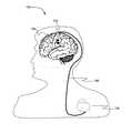
- FIG. 1is a side view depicting a deep brain stimulation system implanted into the body of a patient, according to an embodiment.
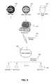
- FIG. 2is a perspective view of a deep brain stimulation lead with four electrodes, according to an embodiment.
- FIG. 3is a perspective view of a deep brain stimulation lead with an array of electrodes, according to an embodiment.
- FIG. 4is a flowchart depicting a method of generating stimulation settings for a deep brain stimulation array, according to an embodiment.
- FIG. 5is a block diagram depicting a deep brain stimulation system and a programmer, according to an embodiment.
- FIG. 6Ais a block diagram depicting a programmer, according to an embodiment.
- FIG. 6Bis a block diagram depicting a pulse generator, according to an embodiment.
- FIG. 7is a simulated view of a discretized brain volume according to an embodiment.
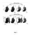
- FIG. 8is a simulated view of the results of generating stimulation settings according to embodiments.
- FIG. 1depicts an exemplary DBS system 100 including a lead 102 comprising one or more electrodes 104 implanted within the thalamus of the brain of a patient.
- Lead 102is in electrical connection via an optional extension 106 to a pulse generator 108 .
- pulse generator 108can be implanted or external, and DBS lead 102 can be targeted to any brain region.
- FIG. 2depicts a detailed view of lead 102 with four circumpolar electrodes 104 a - d .
- FIG. 3depicts a DBS array (DBSA) lead 202 with a greater number of electrodes 104 spaced radially and transversely along lead 202 .
- Leads 102 and 202can include an insulating layer surrounding conductors (not shown) providing electrical connection from electrodes 104 to pulse generator 108 .
- Leads 102 and 202are examples of suitable leads, and other configurations, arrangements and types of leads can be used in various embodiments discussed herein.
- Embodiments of the present disclosureare directed to determining and providing therapies by electrical stimulation of one or more electrodes 104 by pulse generator 108 .
- FIG. 4is a flowchart depicting an overview of a method by which pulse generator 108 can be programmed with settings for each electrode that provide maximum stimulation to one or more target regions while minimizing stimulation of side effect regions. Though this will be discussed in more detail below, including in the context of examples of related systems, hardware and other features, the overview related to FIG. 4 can be helpful for appreciating various features individually and in combination.
- brain geometry data unique to a specific patientcan be combined with brain atlas data to generate a discrete brain geometry grid.
- Data regarding the configuration of the electrodes 104 on the implanted lead 102 or 202can be used to generate a finite element model of the electrode configuration at 404 .
- an activation function (AF) value at each of the grid pointscan be calculated and used to construct a theoretical Max Curve at 408 .
- the Max Curverepresents the greatest likelihood for cellular depolarization that can be transferred to any grid point given a fixed amount of current generated by pulse generator 108 .
- the Max Curvecan be used as criteria for convex optimization via one or more optimization methods (such as convex optimization in one embodiment) at 410 to determine how much energy to output to each electrode.
- the solutionscan be compared at 412 , and device programming can be set and/or carried out at 414 . In other embodiments, more or fewer activities can be carried out, such that additional activities not depicted in FIG. 4 can be included, or activities that are depicted can be omitted.
- Embodimentscan include systems of hardware and software adapted to carrying out the activities depicted in FIG. 4 above.
- FIG. 5depicts an example system in which MRI data 520 , brain atlas data 522 and lead configuration data 524 are used by a programmer device 502 and pulse generator 108 in order to provide optimally programmed therapeutic stimulation 532 to electrodes 104 .
- the data sources 520 , 522 , and 524can be used by programmer device 502 to determine stimulation settings 530 that are customized to the patient. In various embodiments, all three data sources 520 , 522 , 524 can be used, or fewer than all three can be used.
- Programmer device 502can be electrically and/or communicatively coupled to or otherwise receive data from some or all of data sources 520 , 522 , 524 .
- Pulse generator 108directs therapeutic stimulation currents 532 according to the stimulation settings 530 , which can be determined by programmer device 502 based at least in part on the data from data sources 520 , 522 , 524 .
- data from different or additional data sourcesalso or instead can be communicated to programmer device 502 for consideration in determining stimulation settings 530 .
- Pulse generator 108is in wired or wireless communication with programmer device 502 .
- Programmer device 502can be a handheld device, laptop or desktop computer, server, tablet, cellular or smart phone or other computing device capable of communication with pulse generator 108 .
- Programmer device 502can present a user interface adapted to allow a user, such as a clinician, patient, or researcher, to review, monitor, and update device data and settings.
- programmer device 502can comprise a brain geometry engine 604 , lead data engine 606 , discretization engine 608 , and optimization engine 610 .
- Engines 604 , 606 , 608 , 610can be software, firmware, hardware or combinations thereof in embodiments and can comprise or be controlled, executed and/or coupled by a processor, such as a microprocessor, or other computing device. In still other embodiments, engines 604 , 606 , 608 , 610 can be different functions, routines, algorithms, functional units, of a processor or other device. Examples of the tasks, activities and other characteristics of engines 604 , 606 , 608 , 610 are discussed below. Other components of programmer 502 , including hardware and software components, can be included but are not specifically depicted in FIG. 6A .
- pulse generator 108can comprise a processor 620 and a memory 630 .
- Memory 630can include storage for stimulation settings 530 for each of electrodes 104 present on lead 102 or 202 .
- Stimulation settings 530can be, for example, an array, hash table, dictionary, database or other data structure keyed to each electrode 104 . The value at each key can be the amount of current (for example, in milliamps) to be directed to each electrode 104 during a therapy pulse.
- Stimulation settings 530can also include other data items such as pulse time, pulse interval, or current or voltage timing voltages for ramped or shaped pulses.
- Pulse generator 108can also have a communication engine, capable of wired or wireless communication with programmer device 502 . Pulse generator 108 can also have one or more sensing engines capable of interpreting data sensed by electrodes 104 or via sensors within pulse generator 108 itself. Pulse generator 108 can have a stimulation engine 640 capable of independent current-controlled stimulation through each electrode 104 provided. In embodiments, pulse generator 108 can house any of brain geometry engine 604 , lead data engine 606 , discretization engine 608 , and optimization engine 610 instead of or in addition to the engines in programmer 502 .
- pulse generator 108can provide therapy to brain or other tissue by directing pulses of electrical current to each electrode 104 based on the values stored in stimulation settings 530 .
- patient and lead specific datacan be combined by programmer 502 in order to determine optimum stimulation settings 530 .
- each of the enginescan be adapted to perform one or more of the activities of the method discussed regarding FIG. 4 , for example.
- Brain geometry engine 604is adapted to receive brain geometry data and generate a three-dimensional (3D) rectangular grid of multiple layers corresponding to the tissue that is the target of stimulation (i.e., generate a discrete brain grid at 402 of FIG. 4 ).
- Brain geometry datacan include MRI data 520 which can be produced via magnetic resonance imaging (MRI) of the patient.
- MRI data 520can comprise susceptibility weighted imaging (SWI) in one embodiment.
- brain geometry engine 604then can obtain coronal images from the MM data and use those images to contour the target tissue.
- brain geometry engine 604can align the acquired SWI data to the anterior commissure (AC)-posterior commissure (PC) plane and slice it to produce serial coronal sections. These coronal sections, or images, can be analyzed to identify those that span the target tissue and matched to places from a tissue atlas (for example, a brain atlas 522 ) in order to extract the contours of the target tissue.
- ACanterior commissure
- PCposterior commissure
- Brain geometry engine 604can then map the contours onto a 3D rectangular grid of axon nodal locations (e.g., in both the afferent and efferent directions from thalamus) as can be seen in FIG. 7 .
- axon nodal locationse.g., in both the afferent and efferent directions from thalamus
- Lead data engine 606is adapted to generate and store a finite element model (FEM) of the voltage distribution resulting from electrical stimulation through each of electrodes 104 on lead 102 or 202 (i.e., generate a finite element DBSA model at 404 of FIG. 4 ).
- FEMfinite element model
- the electrode surfacescan be designated as boundary current sources, and the walls of the bulk tissue cylinder can be set to ground.
- the voltage distributions resulting from electrical stimulation through the electrodescan be calculated, such as via the finite element method by solving Poisson's equation. Stimulation then can be performed for each electrode 104 .
- the stimulationcomprises monopolar cathodic or anodic stimulation (e.g., at ⁇ 1 mA), with each of the electrodes acting as the cathode and then the anode (or vice-versa).
- Programmer device 502can calculate the finite element model, or the calculated data can be provided to programmer device 502 by a user.
- Programmer device 502can optionally store finite element models for multiple forms of leads 102 or 202 .
- Discretization engine 608is configured to determine the maximum AF value possible at each point in the grid produced by brain geometry engine 604 , and to construct the theoretical maximum curve also known as the Max Curve (such as at 406 and 408 in FIG. 4 ). In one embodiment, discretization engine 608 first calculates the activation function values at each grid point along the fiber direction. This can be done, for example, using the following formula in one embodiment:
- V ⁇ x 2V ⁇ ( x + ⁇ ⁇ ⁇ x ) - 2 ⁇ V ⁇ ( x ) + V ⁇ ( x - ⁇ ⁇ ⁇ x ) ⁇ ⁇ ⁇ x 2 in which x is a position along the direction of the fibers, V is the voltage value as a function of position, and ⁇ x is the internodal distance.
- the AFis the second spatial derivative of the voltage within the target tissue at each grid point.
- This formulation for the AFis just one example, however, and those skilled in the art will appreciate that choice of other formulations can be made in other embodiments.
- other functional derivativescan be used in place of AF to represent depolarization at the grid points. This includes first spatial derivatives as well as second spatial derivatives that incorporate multiple fiber directions. Points that overlap spatially with the DBSA can also be discarded.
- the AF values for the remaining n pointscan be stored in a matrix.
- the matrixcan comprise an m ⁇ n matrix C, where m is the total number electrodes, the i th row contains the AF values resulting from stimulation through the i th electrode alone, delivering ⁇ 1 mA monopolar cathodic current.
- An example of matrix Cis:
- each grid pointrepresents the center of a membrane compartment and has potential to be the point of initiation of an action potential.
- Positive AF valuesare responsible for directly depolarizing the cell membrane and are considered here as potential initiation sites for action potential generation.
- Negative AF valuesrepresent direct hyperpolarization of the cell membrane and thus can limit the likelihood of generating action potentials.
- Optimization engine 610can use the Max Curve values calculated by discretization engine 608 as a goal to reach when determining optimum stimulation settings 530 (such as at 410 of FIG. 4 ).
- Optimization engine 608can then attempt to minimize this discrepancy by one of a variety of optimization methods using well-posed problems, which have unique and global minimums. These optimization methods can include, but are not limited to, linear programming, quadratic programming, and maximum deviation. An example of each method is given below.
- linear programmingcan be used to minimize the difference between the Max Curve and the Actual Curve by solving:
- quadratic programmingcan be used to minimize the square of the difference between the Max Curve and the Actual Curve by solving:
- the maximum deviation (MD) between the Max Curve and the Actual Curvecan be used to solve the following convex optimization problem:
- the equationscan be constrained by assuming that the sum of currents through all electrodes ( ⁇ I k ) be equal to the maximum allowable current (e.g., 1 mA), and that the current through each electrode I k be greater than or equal to zero. It will be appreciated, however, that these constraints are arbitrarily defined and can be adjusted as necessary. In embodiments, the constraints can be defined in the context of using total current amplitudes that do not express stimulation-evoked side effects. In embodiments, the constraints can be defined based on user-specific battery power constraints, for example, by raising or lowering the total sum of the currents.
- one or more side effect regionscan be incorporated within the objective function so optimization engine 610 can generate stimulation settings 530 that maximally stimulate a region or regions of interest while minimally stimulating one or more side effect regions within the brain. This can be done by summing the side effect region(s) with the region(s) of interest. This sum has coefficients that represent the relative weightings of the region(s) of interest and the side effect region(s). Optimization engine 610 can allow for the adjustment of the weighting as desired to increase stimulation of the region(s) of interest while minimizing side effects.
- this weighting-based programming approachrequires only adjusting a single variable, which significantly reduces the complexity of programming even below current clinical approaches. Notably, this simplification still leverages the current steering capabilities of high density DBS arrays.
- the constraints on the current through each electrode, I kcan be adjusted to support optimization of anodal as well as cathodal current by allowing I k to be less than zero. This can enable bipolar or multi-polar combinations to be included as well.
- FIG. 8depicts example therapy configurations generated via each of the MD method 802 , QP method 804 , and LP method 806 for a device implanted in the thalamus of a non-human primate with a DBS array having 32 electrodes.
- Each potential configuration 802 , 804 , 806is a group of stimulation settings 530 that can be provide to, or programmed into, pulse generator 108 .
- each electrode 1 - 32is assigned a color corresponding to the amount of current assigned to it for each pulse.
- the MD method 802produces the most active contacts
- the LP method 806has the smallest number of contacts with all of the current being supplied to electrode 18 .
- optimization engine 610can generate solutions for each optimization method and present them to the user of programmer device 502 to choose the ideal therapy configuration for the patient. In other embodiments, optimization engine 610 can select among the solutions and apply the therapy configuration directly (such as at 414 of FIG. 4 ).
- the chosen solutionmight be the solution that activates the most (or the fewest) electrodes. In other embodiments, the chosen solution may be one that avoids activating certain electrodes. In still other embodiments, the chosen solution may involve averaging the current values at each electrode across the potential solutions. Yet further embodiments may use the other criteria, such as power consumption, or a combination of criteria in order to choose a solution.
- Embodiments of this disclosurepresent several advantages over conventional methods and systems. For example, embodiments allow for automated programming of deep brain stimulation settings via tools that are simple to implement and use. The programming can be achieved quickly and efficiently and is thus amenable to deployment as part of a ⁇ 1 hr clinical visit.
- Embodimentsalso allow for full exploration of the potential capabilities of a DBS array that would be unable to be manually navigated.
- Embodimentsprovide definitive solutions to optimal stimulating electrode configurations and are software-based and not reliant on hardware sensing capabilities, or the continuous sensing of new patient data.
- the disclosed embodimentsare also patient-specific as opposed to relying on accumulated patient data to map out potential therapeutic targets for stimulation in a new patient. Accumulation of such patient databases is not feasible for those who do not have direct access to such data. Although stimulation targets for certain disorders (such as Parkinson's disease and Essential tremor) are well established, therapeutic “hot spots” may be different from patient to patient and cannot be generalized.
- Embodimentsuse patient-specific data (for example, MRI data) to identify the therapeutic target region, and maximize the probability of neuronal activation based on theories of cellular excitation.
- Embodimentsalso do not rely on resource-heavy simulations. While it is possible to empirically determine the volume of tissue activated from virtual stimulation of realistic neuron models, such an approach would have to consider many different scenarios, including locations and orientations of the neurons with respect to the DBS array, as well as the electrode combinations and current distributions to use.
- a method for determining a stimulation setting for each electrode in a deep brain stimulation array having one or more electrodescomprises receiving brain geometry data; receiving lead geometry data; generating, from the brain geometry data and the lead geometry data, one or more grid points representing a target tissue to be activated; calculating a maximum activation function value for each of the one or more grid points; and performing a convex optimization method to determine a set of stimulation settings for each electrode such that an actual activation function value for each grid point is as close to the maximum activation function value for the grid point.
- the convex optimization methodcan minimize the maximum deviation between the actual activation function value and the maximum activation function value for each axonal grid point.
- the convex optimization methodcan minimize the sum of the square of the differences between the actual activation function value and the maximum activation function value for each grid point.
- the convex optimization methodcan minimize the sum of the differences between the actual activation function value and the maximum activation function value for each axonal grid point.
- the stimulation settingscan be configured to avoid activation of non-target tissue such that the method further comprises identifying one or more grid points representing non-target tissue to be avoided when stimulating through the one or more electrodes; determining a set of stimulation settings for at least one of the one or more electrodes such that an actual activation function value for each of the one or more non-target tissue grid points is as close as possible to the minimum activation function value calculated for each of the one or more grid points; and including the set of stimulation settings for at least one of the one or more electrodes in the providing to the pulse generator.
- computing devices, microprocessors and other computer or computing devices discussed hereincan be any programmable device that accepts digital data as input, is configured to process the input according to instructions or algorithms, and provides results as outputs.
- computing, processor and/or other such devices discussed hereincan be, comprise, contain or be coupled to a central processing unit (CPU) configured to carry out the instructions of a computer program.
- CPUcentral processing unit
- Computing, processor and/or other such devices discussed hereinare therefore configured to perform basic arithmetical, logical, and input/output operations.
- Memorycan comprise volatile or non-volatile memory as required by the coupled computing device or processor to not only provide space to execute the instructions or algorithms, but to provide the space to store the instructions themselves.
- volatile memorycan include random access memory (RAM), dynamic random access memory (DRAM), or static random access memory (SRAM), for example.
- non-volatile memorycan include read-only memory, flash memory, ferroelectric RAM, hard disk, floppy disk, magnetic tape, or optical disc storage, for example.
- the system or components thereofcan comprise or include various engines, each of which is constructed, programmed, configured, or otherwise adapted, to autonomously carry out a function or set of functions.
- engineas used herein is defined as a real-world device, component, or arrangement of components implemented using hardware, such as by an application specific integrated circuit (ASIC) or field-programmable gate array (FPGA), for example, or as a combination of hardware and software, such as by a microprocessor system and a set of program instructions that adapt the engine to implement the particular functionality, which (while being executed) transform the microprocessor system into a special-purpose device.
- ASICapplication specific integrated circuit
- FPGAfield-programmable gate array
- An enginecan also be implemented as a combination of the two, with certain functions facilitated by hardware alone, and other functions facilitated by a combination of hardware and software.
- at least a portion, and in some cases, all, of an enginecan be executed on the processor(s) of one or more computing platforms that are made up of hardware (e.g., one or more processors, data storage devices such as memory or drive storage, input/output facilities such as network interface devices, video devices, keyboard, mouse or touchscreen devices, etc.) that execute an operating system, system programs, and application programs, while also implementing the engine using multitasking, multithreading, distributed (e.g., cluster, peer-peer, cloud, etc.) processing where appropriate, or other such techniques.
- hardwaree.g., one or more processors, data storage devices such as memory or drive storage, input/output facilities such as network interface devices, video devices, keyboard, mouse or touchscreen devices, etc.
- multitaskingmultithreading
- distributede.g., cluster, peer-peer, cloud, etc.
- each enginecan be realized in a variety of physically realizable configurations, and should generally not be limited to any particular implementation exemplified herein, unless such limitations are expressly called out.
- an enginecan itself be composed of more than one sub-engines, each of which can be regarded as an engine in its own right.
- each of the various enginescorresponds to a defined autonomous functionality; however, it should be understood that in other contemplated embodiments, each functionality can be distributed to more than one engine.
- multiple defined functionalitiesmay be implemented by a single engine that performs those multiple functions, possibly alongside other functions, or distributed differently among a set of engines than specifically illustrated in the examples herein.
Landscapes
- Health & Medical Sciences (AREA)
- Engineering & Computer Science (AREA)
- General Health & Medical Sciences (AREA)
- Radiology & Medical Imaging (AREA)
- Veterinary Medicine (AREA)
- Public Health (AREA)
- Neurosurgery (AREA)
- Biomedical Technology (AREA)
- Nuclear Medicine, Radiotherapy & Molecular Imaging (AREA)
- Neurology (AREA)
- Life Sciences & Earth Sciences (AREA)
- Animal Behavior & Ethology (AREA)
- Psychology (AREA)
- Heart & Thoracic Surgery (AREA)
- Cardiology (AREA)
- Human Computer Interaction (AREA)
- Electrotherapy Devices (AREA)
Abstract
Description
in which x is a position along the direction of the fibers, V is the voltage value as a function of position, and Δx is the internodal distance. In other words, the AF is the second spatial derivative of the voltage within the target tissue at each grid point. This formulation for the AF is just one example, however, and those skilled in the art will appreciate that choice of other formulations can be made in other embodiments. Notably, other functional derivatives can be used in place of AF to represent depolarization at the grid points. This includes first spatial derivatives as well as second spatial derivatives that incorporate multiple fiber directions. Points that overlap spatially with the DBSA can also be discarded.
Claims (10)
Priority Applications (1)
| Application Number | Priority Date | Filing Date | Title |
|---|---|---|---|
| US15/291,628US10561848B2 (en) | 2015-10-13 | 2016-10-12 | Systems and methods for programming and operating deep brain stimulation arrays |
Applications Claiming Priority (2)
| Application Number | Priority Date | Filing Date | Title |
|---|---|---|---|
| US201562240644P | 2015-10-13 | 2015-10-13 | |
| US15/291,628US10561848B2 (en) | 2015-10-13 | 2016-10-12 | Systems and methods for programming and operating deep brain stimulation arrays |
Publications (2)
| Publication Number | Publication Date |
|---|---|
| US20170100601A1 US20170100601A1 (en) | 2017-04-13 |
| US10561848B2true US10561848B2 (en) | 2020-02-18 |
Family
ID=58499261
Family Applications (1)
| Application Number | Title | Priority Date | Filing Date |
|---|---|---|---|
| US15/291,628Active2037-05-23US10561848B2 (en) | 2015-10-13 | 2016-10-12 | Systems and methods for programming and operating deep brain stimulation arrays |
Country Status (1)
| Country | Link |
|---|---|
| US (1) | US10561848B2 (en) |
Cited By (2)
| Publication number | Priority date | Publication date | Assignee | Title |
|---|---|---|---|---|
| US12076564B2 (en) | 2020-04-14 | 2024-09-03 | Medtronic, Inc. | Patient specific optimization algorithm |
| US12274878B2 (en) | 2020-11-06 | 2025-04-15 | Medtronic, Inc. | Low healthcare provider interaction and outcome based programming |
Families Citing this family (10)
| Publication number | Priority date | Publication date | Assignee | Title |
|---|---|---|---|---|
| US9974959B2 (en) | 2014-10-07 | 2018-05-22 | Boston Scientific Neuromodulation Corporation | Systems, devices, and methods for electrical stimulation using feedback to adjust stimulation parameters |
| US11298553B2 (en)* | 2018-04-27 | 2022-04-12 | Boston Scientific Neuromodulation Corporation | Multi-mode electrical stimulation systems and methods of making and using |
| EP3784332B1 (en) | 2018-04-27 | 2023-04-26 | Boston Scientific Neuromodulation Corporation | Systems for visualizing and programming electrical stimulation |
| EP3846678A4 (en)* | 2018-09-06 | 2022-06-08 | Alpha Omega Engineering Ltd. | Therapeutic space assessment |
| US12403315B2 (en) | 2021-04-27 | 2025-09-02 | Boston Scientific Neuromodulation Corporation | Systems and methods for automated programming of electrical stimulation |
| US12403313B2 (en) | 2021-06-15 | 2025-09-02 | Boston Scientific Neuromodulation Corporation | Methods and systems for estimating neural activation by stimulation using a stimulation system |
| EP4440687A1 (en)* | 2022-02-24 | 2024-10-09 | Boston Scientific Neuromodulation Corporation | Systems and methods for using cost parameters for programming electrical stimulation |
| AU2024229383A1 (en)* | 2023-03-02 | 2025-10-09 | Boston Scientific Neuromodulation Corporation | Neurostimulation device programming using aggregate patient data |
| WO2024191740A1 (en)* | 2023-03-13 | 2024-09-19 | Boston Scientific Neuromodulation Corporation | Neuroanatomy-based comparative search to optimize neurostimulation |
| CN118634422B (en)* | 2024-08-19 | 2024-11-08 | 南昌大学附属康复医院(南昌大学第四附属医院) | Individualized non-invasive deep brain stimulation devices and related products |
Citations (85)
| Publication number | Priority date | Publication date | Assignee | Title |
|---|---|---|---|---|
| US4432360A (en) | 1981-07-06 | 1984-02-21 | Cordis Corporation | Interactive programmer for biomedical implantable devices |
| US5443486A (en) | 1994-09-26 | 1995-08-22 | Medtronic, Inc. | Method and apparatus to limit control of parameters of electrical tissue stimulators |
| US5713922A (en) | 1996-04-25 | 1998-02-03 | Medtronic, Inc. | Techniques for adjusting the locus of excitation of neural tissue in the spinal cord or brain |
| US5814092A (en) | 1996-04-04 | 1998-09-29 | Medtronic Inc. | Neural stimulation techniques with feedback |
| US6463328B1 (en) | 1996-02-02 | 2002-10-08 | Michael Sasha John | Adaptive brain stimulation method and system |
| US6587724B2 (en) | 1999-12-17 | 2003-07-01 | Advanced Bionics Corporation | Magnitude programming for implantable electrical stimulator |
| US6622048B1 (en) | 1999-12-06 | 2003-09-16 | Advanced Bionics Corporation | Implantable device programmer |
| US20040199216A1 (en) | 2003-04-02 | 2004-10-07 | Lee Michael T. | Neurostimulation therapy optimization based on a rated session log |
| WO2004096349A1 (en) | 2003-04-25 | 2004-11-11 | Medtronic, Inc. | Appartus for identifying combinations of electrodes for neurostimulation therapy |
| US20050060001A1 (en) | 2003-09-15 | 2005-03-17 | Ruchika Singhal | Automatic therapy adjustments |
| WO2005028022A1 (en) | 2003-09-15 | 2005-03-31 | Medtronic, Inc. | Selection of neurostimulator parameter configurations using bayesian networks |
| US20050203588A1 (en) | 2002-02-04 | 2005-09-15 | King John D. | Method for optimizing location of implanted electrode array during implant surgery |
| US7003349B1 (en) | 1999-12-16 | 2006-02-21 | St. Jude Medical Ab | Programming system for medical devices |
| US7035690B2 (en) | 2002-11-15 | 2006-04-25 | Medtronic, Inc. | Human-implantable-neurostimulator user interface having multiple levels of abstraction |
| US7110821B1 (en) | 2002-07-10 | 2006-09-19 | Advanced Bionics Corporation | Channel interaction cancellation within a multichannel neural stimulation system |
| US20060217781A1 (en) | 2005-03-24 | 2006-09-28 | John Michael S | Systems and Methods for Treating Disorders of the Central Nervous System by Modulation of Brain Networks |
| US20060235472A1 (en) | 2004-07-20 | 2006-10-19 | Medtronic, Inc. | Therapy programming guidance based on stored programming history |
| US7177674B2 (en) | 2001-10-12 | 2007-02-13 | Javier Echauz | Patient-specific parameter selection for neurological event detection |
| US7181286B2 (en) | 2002-10-31 | 2007-02-20 | Medtronic, Inc. | Distributed system for neurostimulation therapy programming |
| US20070043268A1 (en) | 2005-06-16 | 2007-02-22 | Russell Michael J | Guided Electrical Transcranial Stimulation (GETS) Technique |
| US7187978B2 (en) | 2001-11-01 | 2007-03-06 | Medtronic, Inc. | Method and apparatus for programming an implantable medical device |
| US20070083104A1 (en) | 2004-07-07 | 2007-04-12 | The Cleveland Clinic Foundation | System and method to design structure for delivering electrical energy to tissue |
| US7209787B2 (en) | 1998-08-05 | 2007-04-24 | Bioneuronics Corporation | Apparatus and method for closed-loop intracranial stimulation for optimal control of neurological disease |
| US7239926B2 (en) | 2003-09-15 | 2007-07-03 | Medtronic, Inc. | Selection of neurostimulator parameter configurations using genetic algorithms |
| US7254445B2 (en) | 1996-06-07 | 2007-08-07 | Advanced Neuromodulation Systems, Inc. | Multiprogrammable tissue stimulator and method |
| US20070185544A1 (en) | 2006-01-13 | 2007-08-09 | Vanderbilt University | System and methods of deep brain stimulation for post-operation patients |
| US20070203545A1 (en) | 2006-02-24 | 2007-08-30 | Medtronic, Inc. | User interface with 3D environment for configuring stimulation therapy |
| US20070203538A1 (en) | 2006-02-24 | 2007-08-30 | Medtronic, Inc. | User interface with an atlas for configuring stimulation therapy |
| US7266412B2 (en) | 2003-04-22 | 2007-09-04 | Medtronic, Inc. | Generation of multiple neurostimulation therapy programs |
| WO2007102945A2 (en) | 2006-03-09 | 2007-09-13 | Medtronic, Inc. | Management of multiple stimulation program groups |
| US20070244519A1 (en) | 2006-04-12 | 2007-10-18 | Medtronic, Inc. | Autogeneration of neurostimulation therapy program groups |
| US7305268B2 (en) | 2000-07-13 | 2007-12-04 | Northstar Neurscience, Inc. | Systems and methods for automatically optimizing stimulus parameters and electrode configurations for neuro-stimulators |
| WO2008005513A2 (en) | 2006-07-06 | 2008-01-10 | Regents Of The University Of Minnesota | Analysis of brain patterns using temporal measures |
| US20080027514A1 (en) | 2006-03-23 | 2008-01-31 | Medtronic, Inc. | Guided programming with feedback |
| US7346382B2 (en) | 2004-07-07 | 2008-03-18 | The Cleveland Clinic Foundation | Brain stimulation models, systems, devices, and methods |
| US20080103552A1 (en) | 2006-10-31 | 2008-05-01 | Medtronic, Inc. | Controller for obtaining prescriptive analysis of functionality of implantable medical device leads, system and method therefore |
| WO2008070145A2 (en) | 2006-12-06 | 2008-06-12 | Medtronic, Inc. | User interface with toolbar for programming electrical stimulation therapy |
| US7415308B2 (en) | 2005-02-23 | 2008-08-19 | Medtronic, Inc. | Implantable medical device providing adaptive neurostimulation therapy for incontinence |
| US20080208284A1 (en) | 2005-04-13 | 2008-08-28 | The Cleveland Clinic Foundation | Systems and methods for neuromodulation using pre-recorded waveforms |
| US7463927B1 (en) | 2004-09-02 | 2008-12-09 | Intelligent Neurostimulation Microsystems, Llc | Self-adaptive system for the automatic detection of discomfort and the automatic generation of SCS therapies for chronic pain control |
| US7489970B2 (en) | 2003-04-02 | 2009-02-10 | Medtronic, Inc. | Management of neurostimulation therapy using parameter sets |
| US20090082829A1 (en) | 2007-09-26 | 2009-03-26 | Medtronic, Inc. | Patient directed therapy control |
| US7519431B2 (en) | 2005-04-11 | 2009-04-14 | Medtronic, Inc. | Shifting between electrode combinations in electrical stimulation device |
| US20090105787A1 (en) | 2007-10-17 | 2009-04-23 | Intelect Medical., Inc. | Patient Programmer with Input and Sensing Capabilities |
| WO2009055207A2 (en) | 2007-10-24 | 2009-04-30 | Medtronic, Inc. | Remote management of therapy programming |
| US20090112281A1 (en) | 2007-10-26 | 2009-04-30 | Medtronic, Inc. | Medical device configuration based on sensed brain signals |
| US20090118787A1 (en) | 2007-11-02 | 2009-05-07 | Advanced Bionics Corporation | Closed-loop feedback for steering stimulation energy within tissue |
| US7548786B2 (en) | 2003-04-02 | 2009-06-16 | Medtronic, Inc. | Library for management of neurostimulation therapy programs |
| US7551960B2 (en) | 2005-09-08 | 2009-06-23 | Medtronic, Inc. | External presentation of electrical stimulation parameters |
| WO2009134475A1 (en) | 2008-04-29 | 2009-11-05 | Medtronic, Inc. | Therapy program modification based on a therapy field model |
| US7657319B2 (en) | 2006-02-24 | 2010-02-02 | Medtronic, Inc. | Programming interface with an unwrapped 2D view of a stimulation lead with complex electrode array geometry |
| US7676273B2 (en) | 2006-02-24 | 2010-03-09 | Medtronic, Inc. | Stimulation templates for programming a stimulation lead with complex electrode array geometry |
| US7720548B2 (en) | 2005-04-30 | 2010-05-18 | Medtronic | Impedance-based stimulation adjustment |
| WO2010065888A2 (en) | 2008-12-04 | 2010-06-10 | The Cleveland Clinic Foundation | System and method to define target volume for stimulation in brain |
| US20100228314A1 (en) | 2007-10-24 | 2010-09-09 | Medtronic, Inc. | Remote titration of therapy delivered by an implantable medical device |
| US7801618B2 (en) | 2007-06-22 | 2010-09-21 | Neuropace, Inc. | Auto adjusting system for brain tissue stimulator |
| US7826902B2 (en) | 2006-02-24 | 2010-11-02 | Medtronic, Inc. | User interface with 2D views for configuring stimulation therapy |
| US20110066407A1 (en) | 2006-03-09 | 2011-03-17 | The Cleveland Clinic Foundation | Systems and methods for determining volume of activation for spinal cord and peripheral nerve stimulation |
| EP2321002A1 (en) | 2008-05-15 | 2011-05-18 | Intelect Medical Inc. | Clinician programmer system and method for calculating volumes of activation |
| US7957809B2 (en) | 2005-12-02 | 2011-06-07 | Medtronic, Inc. | Closed-loop therapy adjustment |
| US20110160796A1 (en) | 2009-12-28 | 2011-06-30 | Boston Scientific Neuromodulation Corporation | Automatic evaluation technique for deep brain stimulation programming |
| US20110172737A1 (en) | 2010-01-08 | 2011-07-14 | Medtronic, Inc. | Programming therapy delivered by implantable medical device |
| US20110191275A1 (en) | 2009-08-27 | 2011-08-04 | The Cleveland Clinic Foundation | System and method to estimate region of tissue activation |
| WO2011094752A2 (en) | 2010-02-01 | 2011-08-04 | Orasi Medical, Inc. | Methods and systems for regional synchronous neural interactions analysis |
| US20110264165A1 (en) | 2010-04-27 | 2011-10-27 | Medtronic, Inc. | Stimulation electrode selection |
| US8090446B2 (en) | 2007-04-19 | 2012-01-03 | Advanced Neuromodulation Systems, Inc. | Methods and systems for establishing neural stimulation parameters and providing neural stimulation |
| US20120016378A1 (en) | 2010-07-16 | 2012-01-19 | Boston Scientific Neuromodulation Corporation | Systems and methods for radial steering of electrode arrays |
| US8121694B2 (en) | 2007-10-16 | 2012-02-21 | Medtronic, Inc. | Therapy control based on a patient movement state |
| US8180601B2 (en) | 2006-03-09 | 2012-05-15 | The Cleveland Clinic Foundation | Systems and methods for determining volume of activation for deep brain stimulation |
| US8180451B2 (en) | 2004-03-04 | 2012-05-15 | Advanced Neuromodulation Systems, Inc. | System and method for programming an implantable pulse generator |
| US8290596B2 (en) | 2007-09-26 | 2012-10-16 | Medtronic, Inc. | Therapy program selection based on patient state |
| US20120277828A1 (en) | 2011-04-29 | 2012-11-01 | Spinal Modulation, Inc. | Methods, devices and systems for efficiently programming neurostimulation |
| US8483836B2 (en) | 2011-09-07 | 2013-07-09 | Greatbatch Ltd. | Automated search to identify a location for electrical stimulation to treat a patient |
| WO2013162681A1 (en) | 2012-04-23 | 2013-10-31 | Medtronic, Inc. | Electrode selection based on current source density analysis |
| US8620452B2 (en) | 2006-06-30 | 2013-12-31 | Medtronic, Inc. | Selecting electrode combinations for stimulation therapy |
| US8649845B2 (en) | 2010-10-19 | 2014-02-11 | The Cleveland Clinic Foundation | Methods for identifying target stimulation regions associated with therapeutic and non-therapeutic clinical outcomes for neural stimulation |
| US8694127B2 (en) | 2010-09-21 | 2014-04-08 | Boston Scientific Neuromodulation Corporation | Systems and methods for making and using radially-aligned segmented electrodes for leads of electrical stimulation systems |
| US8712539B2 (en) | 2006-04-12 | 2014-04-29 | Medtronic, Inc. | Rule-based stimulation program search |
| US8725269B2 (en) | 2006-03-09 | 2014-05-13 | Medtronic, Inc. | Global parameter adjustment for multiple stimulation programs |
| US8757485B2 (en) | 2012-09-05 | 2014-06-24 | Greatbatch Ltd. | System and method for using clinician programmer and clinician programming data for inventory and manufacturing prediction and control |
| US8781592B2 (en) | 2011-09-07 | 2014-07-15 | Greatbatch Ltd. | Identifying an area for electrical stimulation to treat a patient |
| US8805518B2 (en) | 2008-05-09 | 2014-08-12 | Medtronic, Inc. | Peripheral nerve field stimulation control |
| US8838242B2 (en) | 2008-04-30 | 2014-09-16 | Medtronic, Inc. | Pre-configuration of electrode measurement of an implantable medical device, system and method therefore |
| US20140350634A1 (en) | 2013-05-21 | 2014-11-27 | Duke University | Devices, systems and methods for deep brain stimulation parameters |
| US8914121B2 (en) | 2009-04-16 | 2014-12-16 | Boston Scientific Neuromodulation Corporation | Deep brain stimulation current steering with split electrodes |
- 2016
- 2016-10-12USUS15/291,628patent/US10561848B2/enactiveActive
Patent Citations (105)
| Publication number | Priority date | Publication date | Assignee | Title |
|---|---|---|---|---|
| US4432360A (en) | 1981-07-06 | 1984-02-21 | Cordis Corporation | Interactive programmer for biomedical implantable devices |
| US5443486A (en) | 1994-09-26 | 1995-08-22 | Medtronic, Inc. | Method and apparatus to limit control of parameters of electrical tissue stimulators |
| US6463328B1 (en) | 1996-02-02 | 2002-10-08 | Michael Sasha John | Adaptive brain stimulation method and system |
| US5814092A (en) | 1996-04-04 | 1998-09-29 | Medtronic Inc. | Neural stimulation techniques with feedback |
| US5713922A (en) | 1996-04-25 | 1998-02-03 | Medtronic, Inc. | Techniques for adjusting the locus of excitation of neural tissue in the spinal cord or brain |
| US7254445B2 (en) | 1996-06-07 | 2007-08-07 | Advanced Neuromodulation Systems, Inc. | Multiprogrammable tissue stimulator and method |
| US7209787B2 (en) | 1998-08-05 | 2007-04-24 | Bioneuronics Corporation | Apparatus and method for closed-loop intracranial stimulation for optimal control of neurological disease |
| US6622048B1 (en) | 1999-12-06 | 2003-09-16 | Advanced Bionics Corporation | Implantable device programmer |
| US7003349B1 (en) | 1999-12-16 | 2006-02-21 | St. Jude Medical Ab | Programming system for medical devices |
| US6587724B2 (en) | 1999-12-17 | 2003-07-01 | Advanced Bionics Corporation | Magnitude programming for implantable electrical stimulator |
| US7305268B2 (en) | 2000-07-13 | 2007-12-04 | Northstar Neurscience, Inc. | Systems and methods for automatically optimizing stimulus parameters and electrode configurations for neuro-stimulators |
| US7177674B2 (en) | 2001-10-12 | 2007-02-13 | Javier Echauz | Patient-specific parameter selection for neurological event detection |
| US7187978B2 (en) | 2001-11-01 | 2007-03-06 | Medtronic, Inc. | Method and apparatus for programming an implantable medical device |
| US20050203588A1 (en) | 2002-02-04 | 2005-09-15 | King John D. | Method for optimizing location of implanted electrode array during implant surgery |
| US7146223B1 (en) | 2002-02-04 | 2006-12-05 | Advanced Bionics Corporation | Method for optimizing search for spinal cord stimulation parameter settings |
| US7110821B1 (en) | 2002-07-10 | 2006-09-19 | Advanced Bionics Corporation | Channel interaction cancellation within a multichannel neural stimulation system |
| US7181286B2 (en) | 2002-10-31 | 2007-02-20 | Medtronic, Inc. | Distributed system for neurostimulation therapy programming |
| US7035690B2 (en) | 2002-11-15 | 2006-04-25 | Medtronic, Inc. | Human-implantable-neurostimulator user interface having multiple levels of abstraction |
| US7548786B2 (en) | 2003-04-02 | 2009-06-16 | Medtronic, Inc. | Library for management of neurostimulation therapy programs |
| US7489970B2 (en) | 2003-04-02 | 2009-02-10 | Medtronic, Inc. | Management of neurostimulation therapy using parameter sets |
| US20040199216A1 (en) | 2003-04-02 | 2004-10-07 | Lee Michael T. | Neurostimulation therapy optimization based on a rated session log |
| US7266412B2 (en) | 2003-04-22 | 2007-09-04 | Medtronic, Inc. | Generation of multiple neurostimulation therapy programs |
| US7463928B2 (en) | 2003-04-25 | 2008-12-09 | Medtronic, Inc. | Identifying combinations of electrodes for neurostimulation therapy |
| US20040267330A1 (en) | 2003-04-25 | 2004-12-30 | Lee Michael T. | Generation of theraphy programs and program groups |
| WO2004096349A1 (en) | 2003-04-25 | 2004-11-11 | Medtronic, Inc. | Appartus for identifying combinations of electrodes for neurostimulation therapy |
| US8649872B2 (en) | 2003-04-25 | 2014-02-11 | Medtronic, Inc. | Identifying combinations of electrodes for neurostimulation therapy |
| US7184837B2 (en) | 2003-09-15 | 2007-02-27 | Medtronic, Inc. | Selection of neurostimulator parameter configurations using bayesian networks |
| US20050060001A1 (en) | 2003-09-15 | 2005-03-17 | Ruchika Singhal | Automatic therapy adjustments |
| WO2005028022A1 (en) | 2003-09-15 | 2005-03-31 | Medtronic, Inc. | Selection of neurostimulator parameter configurations using bayesian networks |
| US7239926B2 (en) | 2003-09-15 | 2007-07-03 | Medtronic, Inc. | Selection of neurostimulator parameter configurations using genetic algorithms |
| US8180451B2 (en) | 2004-03-04 | 2012-05-15 | Advanced Neuromodulation Systems, Inc. | System and method for programming an implantable pulse generator |
| US7680526B2 (en) | 2004-07-07 | 2010-03-16 | The Cleveland Clinic Foundation | System and method for obtaining a volume of influence based on non-uniform tissue conductivity data |
| US20070083104A1 (en) | 2004-07-07 | 2007-04-12 | The Cleveland Clinic Foundation | System and method to design structure for delivering electrical energy to tissue |
| US8538543B2 (en)* | 2004-07-07 | 2013-09-17 | The Cleveland Clinic Foundation | System and method to design structure for delivering electrical energy to tissue |
| US8379952B2 (en) | 2004-07-07 | 2013-02-19 | The Cleveland Clinic Foundation | Method and device for displaying predicted volume of influence with patient-specific atlas of neural tissue |
| US7904134B2 (en) | 2004-07-07 | 2011-03-08 | The Cleveland Clinic Foundation | Brain stimulation models, systems, devices, and methods |
| US7860548B2 (en) | 2004-07-07 | 2010-12-28 | The Cleveland Clinic Foundation | Tissue stimulation models, systems, devices, and methods |
| US7346382B2 (en) | 2004-07-07 | 2008-03-18 | The Cleveland Clinic Foundation | Brain stimulation models, systems, devices, and methods |
| US20060235472A1 (en) | 2004-07-20 | 2006-10-19 | Medtronic, Inc. | Therapy programming guidance based on stored programming history |
| US7463927B1 (en) | 2004-09-02 | 2008-12-09 | Intelligent Neurostimulation Microsystems, Llc | Self-adaptive system for the automatic detection of discomfort and the automatic generation of SCS therapies for chronic pain control |
| US7415308B2 (en) | 2005-02-23 | 2008-08-19 | Medtronic, Inc. | Implantable medical device providing adaptive neurostimulation therapy for incontinence |
| US20060217781A1 (en) | 2005-03-24 | 2006-09-28 | John Michael S | Systems and Methods for Treating Disorders of the Central Nervous System by Modulation of Brain Networks |
| US7519431B2 (en) | 2005-04-11 | 2009-04-14 | Medtronic, Inc. | Shifting between electrode combinations in electrical stimulation device |
| US20080208284A1 (en) | 2005-04-13 | 2008-08-28 | The Cleveland Clinic Foundation | Systems and methods for neuromodulation using pre-recorded waveforms |
| US7720548B2 (en) | 2005-04-30 | 2010-05-18 | Medtronic | Impedance-based stimulation adjustment |
| US20070043268A1 (en) | 2005-06-16 | 2007-02-22 | Russell Michael J | Guided Electrical Transcranial Stimulation (GETS) Technique |
| US7551960B2 (en) | 2005-09-08 | 2009-06-23 | Medtronic, Inc. | External presentation of electrical stimulation parameters |
| US8812126B2 (en) | 2005-11-28 | 2014-08-19 | The Cleveland Clinic Foundation | System and method to define target volume for stimulation of the spinal cord and peripheral nerves |
| US7957809B2 (en) | 2005-12-02 | 2011-06-07 | Medtronic, Inc. | Closed-loop therapy adjustment |
| US20070185544A1 (en) | 2006-01-13 | 2007-08-09 | Vanderbilt University | System and methods of deep brain stimulation for post-operation patients |
| US7657319B2 (en) | 2006-02-24 | 2010-02-02 | Medtronic, Inc. | Programming interface with an unwrapped 2D view of a stimulation lead with complex electrode array geometry |
| US7826902B2 (en) | 2006-02-24 | 2010-11-02 | Medtronic, Inc. | User interface with 2D views for configuring stimulation therapy |
| US20070203545A1 (en) | 2006-02-24 | 2007-08-30 | Medtronic, Inc. | User interface with 3D environment for configuring stimulation therapy |
| US20070203538A1 (en) | 2006-02-24 | 2007-08-30 | Medtronic, Inc. | User interface with an atlas for configuring stimulation therapy |
| US7676273B2 (en) | 2006-02-24 | 2010-03-09 | Medtronic, Inc. | Stimulation templates for programming a stimulation lead with complex electrode array geometry |
| US8725269B2 (en) | 2006-03-09 | 2014-05-13 | Medtronic, Inc. | Global parameter adjustment for multiple stimulation programs |
| WO2007102945A2 (en) | 2006-03-09 | 2007-09-13 | Medtronic, Inc. | Management of multiple stimulation program groups |
| US20110066407A1 (en) | 2006-03-09 | 2011-03-17 | The Cleveland Clinic Foundation | Systems and methods for determining volume of activation for spinal cord and peripheral nerve stimulation |
| US9067076B2 (en) | 2006-03-09 | 2015-06-30 | Medtronic, Inc. | Management of multiple stimulation program groups |
| US8180601B2 (en) | 2006-03-09 | 2012-05-15 | The Cleveland Clinic Foundation | Systems and methods for determining volume of activation for deep brain stimulation |
| US20080027514A1 (en) | 2006-03-23 | 2008-01-31 | Medtronic, Inc. | Guided programming with feedback |
| US8712539B2 (en) | 2006-04-12 | 2014-04-29 | Medtronic, Inc. | Rule-based stimulation program search |
| US20070244519A1 (en) | 2006-04-12 | 2007-10-18 | Medtronic, Inc. | Autogeneration of neurostimulation therapy program groups |
| US8666506B2 (en) | 2006-06-30 | 2014-03-04 | Medtronic, Inc. | Selecting electrode combinations for stimulation therapy |
| US8620452B2 (en) | 2006-06-30 | 2013-12-31 | Medtronic, Inc. | Selecting electrode combinations for stimulation therapy |
| WO2008005513A2 (en) | 2006-07-06 | 2008-01-10 | Regents Of The University Of Minnesota | Analysis of brain patterns using temporal measures |
| US9101276B2 (en) | 2006-07-06 | 2015-08-11 | Regents Of The University Of Minnesota | Analysis of brain patterns using temporal measures |
| US20080103552A1 (en) | 2006-10-31 | 2008-05-01 | Medtronic, Inc. | Controller for obtaining prescriptive analysis of functionality of implantable medical device leads, system and method therefore |
| WO2008070145A2 (en) | 2006-12-06 | 2008-06-12 | Medtronic, Inc. | User interface with toolbar for programming electrical stimulation therapy |
| US20080215118A1 (en) | 2006-12-06 | 2008-09-04 | Medtronic, Inc. | User interface with toolbar for programming electrical stimulation therapy |
| US8090446B2 (en) | 2007-04-19 | 2012-01-03 | Advanced Neuromodulation Systems, Inc. | Methods and systems for establishing neural stimulation parameters and providing neural stimulation |
| US7801618B2 (en) | 2007-06-22 | 2010-09-21 | Neuropace, Inc. | Auto adjusting system for brain tissue stimulator |
| US20090082829A1 (en) | 2007-09-26 | 2009-03-26 | Medtronic, Inc. | Patient directed therapy control |
| US8290596B2 (en) | 2007-09-26 | 2012-10-16 | Medtronic, Inc. | Therapy program selection based on patient state |
| US8121694B2 (en) | 2007-10-16 | 2012-02-21 | Medtronic, Inc. | Therapy control based on a patient movement state |
| US20090105787A1 (en) | 2007-10-17 | 2009-04-23 | Intelect Medical., Inc. | Patient Programmer with Input and Sensing Capabilities |
| US20100228314A1 (en) | 2007-10-24 | 2010-09-09 | Medtronic, Inc. | Remote titration of therapy delivered by an implantable medical device |
| WO2009055207A2 (en) | 2007-10-24 | 2009-04-30 | Medtronic, Inc. | Remote management of therapy programming |
| US20090112281A1 (en) | 2007-10-26 | 2009-04-30 | Medtronic, Inc. | Medical device configuration based on sensed brain signals |
| US20090118787A1 (en) | 2007-11-02 | 2009-05-07 | Advanced Bionics Corporation | Closed-loop feedback for steering stimulation energy within tissue |
| WO2009134475A1 (en) | 2008-04-29 | 2009-11-05 | Medtronic, Inc. | Therapy program modification based on a therapy field model |
| US8838242B2 (en) | 2008-04-30 | 2014-09-16 | Medtronic, Inc. | Pre-configuration of electrode measurement of an implantable medical device, system and method therefore |
| US8805518B2 (en) | 2008-05-09 | 2014-08-12 | Medtronic, Inc. | Peripheral nerve field stimulation control |
| US8326433B2 (en) | 2008-05-15 | 2012-12-04 | Intelect Medical, Inc. | Clinician programmer system and method for calculating volumes of activation for monopolar and bipolar electrode configurations |
| EP2321002A1 (en) | 2008-05-15 | 2011-05-18 | Intelect Medical Inc. | Clinician programmer system and method for calculating volumes of activation |
| US20110313268A1 (en) | 2008-05-15 | 2011-12-22 | IntElect Medical | Clinician programmer system and method for steering volumes of activation |
| US20130226261A1 (en) | 2008-05-15 | 2013-08-29 | Intelect Medical, Inc. | Clinician programmer system and method for generating interface models and displays of volumes of activation |
| US20110040351A1 (en) | 2008-12-04 | 2011-02-17 | The Cleveland Clinic Foundation | System and method to define target volume for stimulation of the spinal cord and peripheral nerves |
| US8644946B2 (en) | 2008-12-04 | 2014-02-04 | The Cleveland Clinic Foundation | System and method to define target volume for stimulation in brain |
| WO2010065888A2 (en) | 2008-12-04 | 2010-06-10 | The Cleveland Clinic Foundation | System and method to define target volume for stimulation in brain |
| US8914121B2 (en) | 2009-04-16 | 2014-12-16 | Boston Scientific Neuromodulation Corporation | Deep brain stimulation current steering with split electrodes |
| US20110191275A1 (en) | 2009-08-27 | 2011-08-04 | The Cleveland Clinic Foundation | System and method to estimate region of tissue activation |
| US20110160796A1 (en) | 2009-12-28 | 2011-06-30 | Boston Scientific Neuromodulation Corporation | Automatic evaluation technique for deep brain stimulation programming |
| US20110172737A1 (en) | 2010-01-08 | 2011-07-14 | Medtronic, Inc. | Programming therapy delivered by implantable medical device |
| WO2011094752A2 (en) | 2010-02-01 | 2011-08-04 | Orasi Medical, Inc. | Methods and systems for regional synchronous neural interactions analysis |
| US20110264165A1 (en) | 2010-04-27 | 2011-10-27 | Medtronic, Inc. | Stimulation electrode selection |
| US20120016378A1 (en) | 2010-07-16 | 2012-01-19 | Boston Scientific Neuromodulation Corporation | Systems and methods for radial steering of electrode arrays |
| US8694127B2 (en) | 2010-09-21 | 2014-04-08 | Boston Scientific Neuromodulation Corporation | Systems and methods for making and using radially-aligned segmented electrodes for leads of electrical stimulation systems |
| US8649845B2 (en) | 2010-10-19 | 2014-02-11 | The Cleveland Clinic Foundation | Methods for identifying target stimulation regions associated with therapeutic and non-therapeutic clinical outcomes for neural stimulation |
| US20120277828A1 (en) | 2011-04-29 | 2012-11-01 | Spinal Modulation, Inc. | Methods, devices and systems for efficiently programming neurostimulation |
| US8781592B2 (en) | 2011-09-07 | 2014-07-15 | Greatbatch Ltd. | Identifying an area for electrical stimulation to treat a patient |
| US8483836B2 (en) | 2011-09-07 | 2013-07-09 | Greatbatch Ltd. | Automated search to identify a location for electrical stimulation to treat a patient |
| WO2013162681A1 (en) | 2012-04-23 | 2013-10-31 | Medtronic, Inc. | Electrode selection based on current source density analysis |
| US8757485B2 (en) | 2012-09-05 | 2014-06-24 | Greatbatch Ltd. | System and method for using clinician programmer and clinician programming data for inventory and manufacturing prediction and control |
| US20140350634A1 (en) | 2013-05-21 | 2014-11-27 | Duke University | Devices, systems and methods for deep brain stimulation parameters |
Non-Patent Citations (49)
| Title |
|---|
| Application and File History for U.S. Appl. No. 15/794,333, filed Oct. 26, 2017, Inventors: Johnson et al. |
| Barbas et al., Toward Patient-Specific Targeting and Parameter Setting of Deep Brain Stimulation for Relief of Depression, Biol Phychiatry © 2014, pp. 914-196, available at http://dx.doi.org/10.1016/j.biopsych.2014.09.012. |
| Barbe et al., Individualized Current-Shaping Reduces DBS-Induced Dysarthria in Patients with Essential Tremor, © 2014, American Academy of Neurology, 7 pages. |
| Berenstein, Current Steering and Current Focusing in Cochlear Implants: Comparison of Monopolar, Tripolar and Virtual Channel Electrode Configurations, © 2008, pp. 250-260. |
| Bonham, Ben H. et al., Hear Res. , Current Focusing and Steering: Modeling, Physiology and Psychophysics, Aug. 2008, 27 pages. |
| Buhlmann, Modeling of a Segmented Electrode for Desychnronizing Deep Brain Stimulation, Dec. 2011, vol. 4, Article 15, pp. 1-8. |
| Butson, C.R., StimExplorer: Deep Brain Stimulation Parameter Selection Software System, © Springer-Verlag 2007, 97(2), pp. 569-574. |
| Butson, Christopher R., IEEE Trans Vis Comput Graph, Evaluation of Interactive Visualization on Mobile Computing Platforms for Selection of Deep Brain Stimulation Parameters, Jan. 2013, 19(1), pp. 108-117. |
| Butson, Christopher, Patient-Specific Analysis of the Volume of Tissue Activated During Deep Brain Stimulation, NIH Public Access, Jan. 15, 2007, pp. 1-16. |
| Butson, Christopher, Patient-Specific Analysis of the Volume of Tissue Activated During Deep Brain Stimulation, NIH Public Access, Jan. 2008, pp. 1-16. |
| Chatuvedi, Ashutosh et al., Artificial Neural Network Based Characterization of the Volume of Tissue Activated During Deep Brain Stimulation, NIH Public Access, J. Neural Eng. , Oct. 2013, 17 pages. |
| Chatuvedi, Ashutosh et al., Current Steering to Activate Targeted Neural Pathways During Deep Brain Stimulation of the Subthalamic Region, Jul. 2012, 5(3), 16 pages. |
| Chatuvedi, Ashutosh et al., Patient-Specific Models of Deep Brain Stimulation: Influence of Field Model Complexity on Neural Activation Predictions, Apr. 1, 2010, 3(2), 23 pages. |
| Choi, Charles T. M., IEEE, Modeling Deep Brain Stimulation Based on Current Steering Scheme, vol. 47, No. 5, May 2011, pp. 890-893. |
| Cicione, Rosemary, Visual Cortex Response to Paired Stimulation of Retina, Spatiotemporal Interactions in the Visual Cortex Following Paired Electrical Stimulation of the Retina, © 2014, vol. 55, No. 12, pp. 7726-7738. |
| Coenen, V.A. et al., Explaining Clinical Effects of Deep Brain Stimulation Through Simplified Target-Specific Modeling of the Volume of Activated Tissue, AJNR 33, www.ajnr.org, 9 pages. |
| Contarino, M. Fiorella et al., Research Gate, Directional Steering-A Novel Approach to Deep Brain Stimulation, Sep. 2014 and as retrieved on Oct. 2, 2018, 9 pages. |
| Contarino, M. Fiorella et al., Research Gate, Directional Steering—A Novel Approach to Deep Brain Stimulation, Sep. 2014 and as retrieved on Oct. 2, 2018, 9 pages. |
| Dumm, Gerald, Virtual Electrodes by Current Steering in Retinal Prostheses, vol. 55, No. 12, Dec. 2014, available at https://iovs.arvojournals.org/pdfaccess.ashx?url=/data/journals/iovs/933678/, as retrieved on Oct. 3, 2018, pp. 8078-8085. |
| Firszt, Jill B et al., Current Steering Creates Additional Pitch Percepts in Adult Cochlear Implant Recipients, © 2007, Otology & Neurotolgy, Inc. , pp. 629-636. |
| Frankemolle, Anneke M.M., Brain: A Journal of Neurology, Brain 2010: 133, Reversing Cognitive-Motor Impairments in Parkinson's Disease Patients Using a Computational Modelling Approach to Deep Brain Stimulation Programming, pp. 746-761. |
| Horsager, Alan et al., Visual Psychophysics and Physiological Optics, Spatiotemporal Interactions in Retinal Prosthesis Subjects, Feb. 2010, Vo. 51, No. 2, pp. 1223-1233. |
| Hunka, Karen, Journal of Neuroscience Nursing, Nursing Time to Program and Assess Deep Brain Stimulators in Movement Disorder Patients, Aug. 2005, vol. 37, No. 4, pp. 204-210. |
| Jepson, Lauren H. et al., Neurobiology of Disease, Spatially Patterned Electrical Stimulation to Enhance Resolution of Retinal Prostheses, Apr. 2, 2014, 34(14), pp. 4871-4881. |
| Keane, Maureen, NIH Public Access, J. Neural Eng. , Improved Spatial Targeting with Directionally Segmented Deep Brain Stimulation Leads for Treating Essential Tremor, Aug. 2012, 9(4), 18 pages. |
| Kumar, Rajeev, Methods for Programming and Patient Management with Deep Brain Stimulation of the Globus Pallidus for the Treatment of Advanced Parkinson's Disease and Dystonia, Movement Disorders, Mar. 28, 2002, 2 pages. |
| Kuncel, Alex M., Clin Ceurophysiol, Sep. 2008, A Method to Estimate the Spatial Extent of Activation in Thalamic Deep Brain Stimulation, Sep. 2008, 20 pages. |
| Kuncel, Alexis M., Selection of Stimulus Parameters for Deep Brain Stimulation, Science Direct, vol. 115, Issue 11, Nov. 2004, pp. 2431-2441. |
| Martens H.C.F, Clinical Neurophysiology, Spatial Steering of Deep Brain Stimulation Volumes Using a Novel Lead Design, © 2010, 9 pages. |
| McIntyre, Cameron C. et al., 33rd Annual International Conference of the IEEE EMBS, Improving Postural Stability via Computational Modeling Approach to Deep Brain Stimulation Programming, Aug. 30 through Sep. 3, 2011, 2 pages. |
| McIntyre, Cameron C., Clinical Neurophysiology, Electric Field and Stimulating Influence Generated by Deep Brain Stimulation of the Subthatlamic Nucleus, © 2004, 7 pages. |
| McIntyre, Cameron C., Conf Proc IEEE Eng Med Biol. , Customizing Deep Brain Stimulation to the Patient Using Computational Models, 2009, 5 pages. |
| Miocinvoic, Svjetlana, Parkinsonism and Related Disorders, Elservier, Outcomes, Management and Potential Mechanisms of Interleaving Deep Brain Stimulation Settings, 2014, 4 pages. |
| Montgomery Jr, E.B., Deep brain stimulation programming: principles and practice, 2010: Oxford University Press, 201 pages. |
| Moro, Elena, Subthalaic Nucleus Stimulation: Improvements in Outcome with Reprogramming, American Medical Association, © 2006, pp. 1266-1272. |
| Opie, N.L. et al., 35th Annual International Conference of the IEEE EMBS, Current Steering for High Resolution Retinal Implants, © 2013, Jul. 3-7, 2013, 5 pages. |
| Oxford University, Brain: A Journal of Neurology, Steering Technology for Deep Brain Stimulation, © 2014, pp. 1854-1862. |
| Phibbs, Fenna T. et al., Use of Efficacy Probability Maps for the Post-Operative Programming of Deep Brain Stimulation in Essential Tremor, Parkinsonism Relat Disord, Dec. 2014, 11 pages. |
| Pollo Claudio et al., Brain: A Journal of Neurology, Directional Deep Brain Stimulation: An Intraoperative Double-Blind Pilot Study, 2015, 12 pages. |
| Schuurman, Rick et al., Stereotact Funct Neurosurg, Papers Session-Stereotactic Technology , May 29, 2013, 1 page. |
| Schuurman, Rick et al., Stereotact Funct Neurosurg, Papers Session—Stereotactic Technology , May 29, 2013, 1 page. |
| Toader, Emil et al., 32nd Annual International Conference of the IEEE EMBS, Steering Deep Brain Stimulation Fields Using a High Resolution Electrode Array, Aug. 31 through Sep. 4, 2010, 4 pages. |
| Townshend Brent, Reduction of Electrical Interaction in Auditory Prostheses, IEEE Transactions on Biomedical Engineering, vol. BME-34, No. 11, Nov. 1987, pp. 891-897. |
| Veraart, Claude, Selective Control of Muscle Activation with a Multipolar Nerve Cuff Electrode, IEEE Transactions on Biomedical Engineering, vol. 40, No. 7, Jul. 1993, pp. 640-653. |
| Volkmann, Jens et al., Introduction to the Programming of Deep Brain Stimulators, Movement Disorders, vol. 17, Suppl. 3, 2002, pp. S181-S187. |
| Volkmann, Jens, Basic Algorithms for the Programming of Deep Brain Stimulation in Parkinson's Disease, Movement Disorders, vol. 21, Issue S514, Jun. 29, 2006. |
| Xiao, YiZi et al., Theoretical Optimization of Stimulation Strategies for Directionally Segmented Deep Brain Stimulation Electrode Arrays, Dec. 23, 2014, 31 pages. |
| Xiao-Jiang, Feng, Optimal Deep Brain Stimulation of the Subthalamic Nucelus-A Computational Study, Journal of Computational Neuroscience, Dec. 2007. |
| Xiao-Jiang, Feng, Optimal Deep Brain Stimulation of the Subthalamic Nucelus—A Computational Study, Journal of Computational Neuroscience, Dec. 2007. |
Cited By (2)
| Publication number | Priority date | Publication date | Assignee | Title |
|---|---|---|---|---|
| US12076564B2 (en) | 2020-04-14 | 2024-09-03 | Medtronic, Inc. | Patient specific optimization algorithm |
| US12274878B2 (en) | 2020-11-06 | 2025-04-15 | Medtronic, Inc. | Low healthcare provider interaction and outcome based programming |
Also Published As
| Publication number | Publication date |
|---|---|
| US20170100601A1 (en) | 2017-04-13 |
Similar Documents
| Publication | Publication Date | Title |
|---|---|---|
| US10561848B2 (en) | Systems and methods for programming and operating deep brain stimulation arrays | |
| Anderson et al. | Optimized programming algorithm for cylindrical and directional deep brain stimulation electrodes | |
| EP2419171B1 (en) | Neurocranial electrostimulation models | |
| JP6096167B2 (en) | System and method for defining a target volume for brain stimulation | |
| US10426949B2 (en) | Systems and methods for optimizing programming and use of neuromodulation systems | |
| US9259181B2 (en) | Visualizing tissue activated by electrical stimulation | |
| Xiao et al. | Theoretical optimization of stimulation strategies for a directionally segmented deep brain stimulation electrode array | |
| US20120330622A1 (en) | System and method to design structure for delivering electrical energy to tissue | |
| US11904171B2 (en) | Translation between cathodic and anodic neuromodulation parameter settings | |
| WO2012054612A1 (en) | Methods for identifying target stimulation regions associated with therapeutic and non-therapeutic clinical outcomes for neural stimulation | |
| Karimi et al. | Computational analysis of non-invasive deep brain stimulation based on interfering electric fields | |
| Cubo et al. | Optimization of lead design and electrode configuration in deep brain stimulation | |
| Wang et al. | Efficient, Robust and Accurate CNN Predictor for Neuronal Activation in Directional Deep Brain Stimulation | |
| Prieto et al. | Balancing Intensity and Focality in Directional DBS Under Uncertainty: A Simulation Study of Electrode Optimization via a Metaheuristic L1L1 Approach | |
| US20250058120A1 (en) | Integration of fiber tracts into deep brain stimulation targeting | |
| Peña | Optimization Algorithms for Spatially Targeted Deep Brain Stimulation | |
| Zhang | Programming and Sensing with Deep Brain Stimulation Arrays | |
| Frigge et al. | Mixed Integer Linear Programming for Active Contact Selection in Deep Brain Stimulation | |
| Grado | Machine Learning for Deep Brain Stimulation | |
| WO2023200471A9 (en) | Method for focused transcranial electrical current stimulation | |
| Howell et al. | Computational Models to Optimize the Electrodes and Waveforms for Deep Brain Stimulation | |
| Cubo et al. | Model-based Optimization of Lead Configurations in Deep Brain Stimulation | |
| Cubo | Mathematical modeling for optimization of Deep Brain Stimulation |
Legal Events
| Date | Code | Title | Description |
|---|---|---|---|
| AS | Assignment | Owner name:NATIONAL INSTITUTES OF HEALTH (NIH), U.S. DEPT. OF HEALTH AND HUMAN SERVICES (DHHS), U.S. GOVERNMENT, MARYLAND Free format text:CONFIRMATORY LICENSE;ASSIGNOR:UNIVERSITY OF MINNESOTA;REEL/FRAME:040886/0808 Effective date:20161206 Owner name:NATIONAL INSTITUTES OF HEALTH (NIH), U.S. DEPT. OF Free format text:CONFIRMATORY LICENSE;ASSIGNOR:UNIVERSITY OF MINNESOTA;REEL/FRAME:040886/0808 Effective date:20161206 | |
| STPP | Information on status: patent application and granting procedure in general | Free format text:RESPONSE TO NON-FINAL OFFICE ACTION ENTERED AND FORWARDED TO EXAMINER | |
| STPP | Information on status: patent application and granting procedure in general | Free format text:FINAL REJECTION MAILED | |
| STPP | Information on status: patent application and granting procedure in general | Free format text:RESPONSE AFTER FINAL ACTION FORWARDED TO EXAMINER | |
| STPP | Information on status: patent application and granting procedure in general | Free format text:NOTICE OF ALLOWANCE MAILED -- APPLICATION RECEIVED IN OFFICE OF PUBLICATIONS | |
| AS | Assignment | Owner name:REGENTS OF THE UNIVERSITY OF MINNESOTA, MINNESOTA Free format text:ASSIGNMENT OF ASSIGNORS INTEREST;ASSIGNORS:JOHNSON, MATTHEW DOUGLAS;PENA, EDGAR;XIAO, YIZI;SIGNING DATES FROM 20190814 TO 20190815;REEL/FRAME:050203/0689 | |
| STPP | Information on status: patent application and granting procedure in general | Free format text:DOCKETED NEW CASE - READY FOR EXAMINATION | |
| STPP | Information on status: patent application and granting procedure in general | Free format text:NOTICE OF ALLOWANCE MAILED -- APPLICATION RECEIVED IN OFFICE OF PUBLICATIONS | |
| STCF | Information on status: patent grant | Free format text:PATENTED CASE | |
| MAFP | Maintenance fee payment | Free format text:PAYMENT OF MAINTENANCE FEE, 4TH YR, SMALL ENTITY (ORIGINAL EVENT CODE: M2551); ENTITY STATUS OF PATENT OWNER: SMALL ENTITY Year of fee payment:4 |