US10561353B2 - Biocompatible implantable sensor apparatus and methods - Google Patents
Biocompatible implantable sensor apparatus and methodsDownload PDFInfo
- Publication number
- US10561353B2 US10561353B2US15/170,571US201615170571AUS10561353B2US 10561353 B2US10561353 B2US 10561353B2US 201615170571 AUS201615170571 AUS 201615170571AUS 10561353 B2US10561353 B2US 10561353B2
- Authority
- US
- United States
- Prior art keywords
- detector element
- analyte concentration
- enzymatic
- membrane
- spout
- Prior art date
- Legal status (The legal status is an assumption and is not a legal conclusion. Google has not performed a legal analysis and makes no representation as to the accuracy of the status listed.)
- Active, expires
Links
- 238000000034methodMethods0.000titleabstractdescription67
- 239000012528membraneSubstances0.000claimsabstractdescription237
- 239000000463materialSubstances0.000claimsabstractdescription127
- 230000002255enzymatic effectEffects0.000claimsabstractdescription123
- WQZGKKKJIJFFOK-GASJEMHNSA-NGlucoseNatural productsOC[C@H]1OC(O)[C@H](O)[C@@H](O)[C@@H]1OWQZGKKKJIJFFOK-GASJEMHNSA-N0.000claimsabstractdescription116
- 239000008103glucoseSubstances0.000claimsabstractdescription116
- 102000004190EnzymesHuman genes0.000claimsabstractdescription101
- 108090000790EnzymesProteins0.000claimsabstractdescription101
- 210000004369bloodAnatomy0.000claimsabstractdescription94
- 239000008280bloodSubstances0.000claimsabstractdescription94
- 230000004044responseEffects0.000claimsabstractdescription76
- 238000001514detection methodMethods0.000claimsabstractdescription24
- 238000006243chemical reactionMethods0.000claimsabstractdescription14
- 239000012491analyteSubstances0.000claimsdescription163
- 229940088598enzymeDrugs0.000claimsdescription98
- QVGXLLKOCUKJST-UHFFFAOYSA-Natomic oxygenChemical compound[O]QVGXLLKOCUKJST-UHFFFAOYSA-N0.000claimsdescription70
- 239000001301oxygenSubstances0.000claimsdescription70
- 229910052760oxygenInorganic materials0.000claimsdescription70
- 239000000126substanceSubstances0.000claimsdescription41
- 239000011159matrix materialSubstances0.000claimsdescription33
- 239000000758substrateSubstances0.000claimsdescription28
- 102000009027AlbuminsHuman genes0.000claimsdescription25
- 108010088751AlbuminsProteins0.000claimsdescription25
- 238000004891communicationMethods0.000claimsdescription25
- 239000003792electrolyteSubstances0.000claimsdescription25
- 108010015776Glucose oxidaseProteins0.000claimsdescription21
- 239000004366Glucose oxidaseSubstances0.000claimsdescription21
- 229940116332glucose oxidaseDrugs0.000claimsdescription21
- 235000019420glucose oxidaseNutrition0.000claimsdescription21
- 238000012545processingMethods0.000claimsdescription20
- 102000016938CatalaseHuman genes0.000claimsdescription18
- 108010053835CatalaseProteins0.000claimsdescription18
- 238000002513implantationMethods0.000claimsdescription18
- 230000035699permeabilityEffects0.000claimsdescription18
- 230000002209hydrophobic effectEffects0.000claimsdescription15
- 230000003993interactionEffects0.000claimsdescription12
- 239000002001electrolyte materialSubstances0.000claimsdescription11
- 230000000116mitigating effectEffects0.000claimsdescription9
- MHAJPDPJQMAIIY-UHFFFAOYSA-NHydrogen peroxideChemical compoundOOMHAJPDPJQMAIIY-UHFFFAOYSA-N0.000claimsdescription8
- 150000001875compoundsChemical class0.000claimsdescription8
- 241000282414Homo sapiensSpecies0.000claimsdescription5
- 230000001965increasing effectEffects0.000claimsdescription5
- RGHNJXZEOKUKBD-SQOUGZDYSA-MD-gluconateChemical compoundOC[C@@H](O)[C@@H](O)[C@H](O)[C@@H](O)C([O-])=ORGHNJXZEOKUKBD-SQOUGZDYSA-M0.000claimsdescription4
- 229940050410gluconateDrugs0.000claimsdescription4
- 229910010293ceramic materialInorganic materials0.000claimsdescription2
- 230000003247decreasing effectEffects0.000claims2
- 230000001747exhibiting effectEffects0.000claims2
- 239000002210silicon-based materialSubstances0.000claims1
- 238000004519manufacturing processMethods0.000abstractdescription15
- 239000007787solidSubstances0.000abstractdescription10
- 102000004169proteins and genesHuman genes0.000abstractdescription7
- 108090000623proteins and genesProteins0.000abstractdescription7
- 239000006227byproductSubstances0.000abstractdescription3
- 238000002955isolationMethods0.000abstractdescription2
- 210000001519tissueAnatomy0.000description43
- -1U.S. Pat. Nos. 4Chemical compound0.000description16
- 238000012544monitoring processMethods0.000description13
- 238000009792diffusion processMethods0.000description11
- 238000013508migrationMethods0.000description11
- WQZGKKKJIJFFOK-VFUOTHLCSA-Nbeta-D-glucoseChemical compoundOC[C@H]1O[C@@H](O)[C@H](O)[C@@H](O)[C@@H]1OWQZGKKKJIJFFOK-VFUOTHLCSA-N0.000description10
- 210000004204blood vesselAnatomy0.000description10
- 230000005012migrationEffects0.000description10
- 229920002379silicone rubberPolymers0.000description10
- 239000004945silicone rubberSubstances0.000description10
- 239000003431cross linking reagentSubstances0.000description9
- 239000000499gelSubstances0.000description9
- 239000007943implantSubstances0.000description9
- 230000035945sensitivityEffects0.000description9
- 238000010382chemical cross-linkingMethods0.000description8
- 230000000694effectsEffects0.000description8
- 238000005259measurementMethods0.000description8
- 230000008569processEffects0.000description8
- 239000000243solutionSubstances0.000description8
- 238000013459approachMethods0.000description7
- 239000000919ceramicSubstances0.000description7
- 238000001727in vivoMethods0.000description7
- 239000000872bufferSubstances0.000description6
- 235000009508confectioneryNutrition0.000description6
- 238000010276constructionMethods0.000description6
- 230000001276controlling effectEffects0.000description6
- 230000001419dependent effectEffects0.000description6
- 206010012601diabetes mellitusDiseases0.000description6
- 238000004132cross linkingMethods0.000description5
- 238000005538encapsulationMethods0.000description5
- 230000007774longtermEffects0.000description5
- 230000003287optical effectEffects0.000description5
- 229920000642polymerPolymers0.000description5
- 239000011148porous materialSubstances0.000description5
- 230000002792vascularEffects0.000description5
- 108010093096Immobilized EnzymesProteins0.000description4
- 230000008901benefitEffects0.000description4
- 239000000560biocompatible materialSubstances0.000description4
- 230000015572biosynthetic processEffects0.000description4
- 230000015556catabolic processEffects0.000description4
- 238000006731degradation reactionMethods0.000description4
- 230000009969flowable effectEffects0.000description4
- 230000012010growthEffects0.000description4
- NOESYZHRGYRDHS-UHFFFAOYSA-NinsulinChemical compoundN1C(=O)C(NC(=O)C(CCC(N)=O)NC(=O)C(CCC(O)=O)NC(=O)C(C(C)C)NC(=O)C(NC(=O)CN)C(C)CC)CSSCC(C(NC(CO)C(=O)NC(CC(C)C)C(=O)NC(CC=2C=CC(O)=CC=2)C(=O)NC(CCC(N)=O)C(=O)NC(CC(C)C)C(=O)NC(CCC(O)=O)C(=O)NC(CC(N)=O)C(=O)NC(CC=2C=CC(O)=CC=2)C(=O)NC(CSSCC(NC(=O)C(C(C)C)NC(=O)C(CC(C)C)NC(=O)C(CC=2C=CC(O)=CC=2)NC(=O)C(CC(C)C)NC(=O)C(C)NC(=O)C(CCC(O)=O)NC(=O)C(C(C)C)NC(=O)C(CC(C)C)NC(=O)C(CC=2NC=NC=2)NC(=O)C(CO)NC(=O)CNC2=O)C(=O)NCC(=O)NC(CCC(O)=O)C(=O)NC(CCCNC(N)=N)C(=O)NCC(=O)NC(CC=3C=CC=CC=3)C(=O)NC(CC=3C=CC=CC=3)C(=O)NC(CC=3C=CC(O)=CC=3)C(=O)NC(C(C)O)C(=O)N3C(CCC3)C(=O)NC(CCCCN)C(=O)NC(C)C(O)=O)C(=O)NC(CC(N)=O)C(O)=O)=O)NC(=O)C(C(C)CC)NC(=O)C(CO)NC(=O)C(C(C)O)NC(=O)C1CSSCC2NC(=O)C(CC(C)C)NC(=O)C(NC(=O)C(CCC(N)=O)NC(=O)C(CC(N)=O)NC(=O)C(NC(=O)C(N)CC=1C=CC=CC=1)C(C)C)CC1=CN=CN1NOESYZHRGYRDHS-UHFFFAOYSA-N0.000description4
- 239000012466permeateSubstances0.000description4
- 150000002978peroxidesChemical class0.000description4
- 229920002338polyhydroxyethylmethacrylatePolymers0.000description4
- 238000005070samplingMethods0.000description4
- 238000012384transportation and deliveryMethods0.000description4
- 229920003171Poly (ethylene oxide)Polymers0.000description3
- 239000000853adhesiveSubstances0.000description3
- 230000001070adhesive effectEffects0.000description3
- 230000002939deleterious effectEffects0.000description3
- 230000027734detection of oxygenEffects0.000description3
- 238000006911enzymatic reactionMethods0.000description3
- 230000005713exacerbationEffects0.000description3
- 229920001480hydrophilic copolymerPolymers0.000description3
- 229920001477hydrophilic polymerPolymers0.000description3
- 230000002163immunogenEffects0.000description3
- 239000002207metaboliteSubstances0.000description3
- 239000000203mixtureSubstances0.000description3
- 229920002401polyacrylamidePolymers0.000description3
- 239000000376reactantSubstances0.000description3
- 238000011282treatmentMethods0.000description3
- MYMOFIZGZYHOMD-UHFFFAOYSA-NDioxygenChemical compoundO=OMYMOFIZGZYHOMD-UHFFFAOYSA-N0.000description2
- SXRSQZLOMIGNAQ-UHFFFAOYSA-NGlutaraldehydeChemical compoundO=CCCCC=OSXRSQZLOMIGNAQ-UHFFFAOYSA-N0.000description2
- 102000004877InsulinHuman genes0.000description2
- 108090001061InsulinProteins0.000description2
- 241000243142PoriferaSpecies0.000description2
- 230000005875antibody responseEffects0.000description2
- 230000009286beneficial effectEffects0.000description2
- 239000006172buffering agentSubstances0.000description2
- 210000004027cellAnatomy0.000description2
- 239000003795chemical substances by applicationSubstances0.000description2
- 239000000470constituentSubstances0.000description2
- 230000006735deficitEffects0.000description2
- 238000013461designMethods0.000description2
- 239000004205dimethyl polysiloxaneSubstances0.000description2
- 238000005516engineering processMethods0.000description2
- 230000002708enhancing effectEffects0.000description2
- 238000011156evaluationMethods0.000description2
- 239000012530fluidSubstances0.000description2
- 230000001976improved effectEffects0.000description2
- 229940125396insulinDrugs0.000description2
- 230000002452interceptive effectEffects0.000description2
- 230000031700light absorptionEffects0.000description2
- 239000007788liquidSubstances0.000description2
- 230000033001locomotionEffects0.000description2
- 230000004089microcirculationEffects0.000description2
- 239000012982microporous membraneSubstances0.000description2
- 238000000465mouldingMethods0.000description2
- 230000035479physiological effects, processes and functionsEffects0.000description2
- 229920000435poly(dimethylsiloxane)Polymers0.000description2
- 229920001296polysiloxanePolymers0.000description2
- 229920002635polyurethanePolymers0.000description2
- 239000004814polyurethaneSubstances0.000description2
- 238000002560therapeutic procedureMethods0.000description2
- 230000009772tissue formationEffects0.000description2
- 238000012546transferMethods0.000description2
- 238000013519translationMethods0.000description2
- 241000282472Canis lupus familiarisSpecies0.000description1
- 102000008186CollagenHuman genes0.000description1
- 108010035532CollagenProteins0.000description1
- 208000036829Device dislocationDiseases0.000description1
- VGGSQFUCUMXWEO-UHFFFAOYSA-NEtheneChemical compoundC=CVGGSQFUCUMXWEO-UHFFFAOYSA-N0.000description1
- 239000005977EthyleneSubstances0.000description1
- 241000282412HomoSpecies0.000description1
- 102000008100Human Serum AlbuminHuman genes0.000description1
- 108091006905Human Serum AlbuminProteins0.000description1
- JVTAAEKCZFNVCJ-UHFFFAOYSA-MLactateChemical compoundCC(O)C([O-])=OJVTAAEKCZFNVCJ-UHFFFAOYSA-M0.000description1
- 238000004497NIR spectroscopyMethods0.000description1
- 102000004316OxidoreductasesHuman genes0.000description1
- 108090000854OxidoreductasesProteins0.000description1
- 239000004698PolyethyleneSubstances0.000description1
- 239000004743PolypropyleneSubstances0.000description1
- 238000001069Raman spectroscopyMethods0.000description1
- 206010039203Road traffic accidentDiseases0.000description1
- 208000007536ThrombosisDiseases0.000description1
- XSQUKJJJFZCRTK-UHFFFAOYSA-NUreaChemical compoundNC(N)=OXSQUKJJJFZCRTK-UHFFFAOYSA-N0.000description1
- 206010052428WoundDiseases0.000description1
- 230000002159abnormal effectEffects0.000description1
- 230000001133accelerationEffects0.000description1
- 230000002411adverseEffects0.000description1
- 238000004458analytical methodMethods0.000description1
- 210000003484anatomyAnatomy0.000description1
- 238000004873anchoringMethods0.000description1
- 239000012062aqueous bufferSubstances0.000description1
- 238000003491arrayMethods0.000description1
- 210000001367arteryAnatomy0.000description1
- 238000003556assayMethods0.000description1
- 239000011230binding agentSubstances0.000description1
- 239000012620biological materialSubstances0.000description1
- 230000033228biological regulationEffects0.000description1
- 230000008081blood perfusionEffects0.000description1
- 239000004202carbamideSubstances0.000description1
- 230000003197catalytic effectEffects0.000description1
- 229920002301cellulose acetatePolymers0.000description1
- 239000013043chemical agentSubstances0.000description1
- 230000035602clottingEffects0.000description1
- 238000000576coating methodMethods0.000description1
- 229920001436collagenPolymers0.000description1
- 239000002131composite materialSubstances0.000description1
- 229920001577copolymerPolymers0.000description1
- 230000002596correlated effectEffects0.000description1
- 230000000875corresponding effectEffects0.000description1
- 238000011161developmentMethods0.000description1
- 230000018109developmental processEffects0.000description1
- 238000010586diagramMethods0.000description1
- 229910001882dioxygenInorganic materials0.000description1
- LOKCTEFSRHRXRJ-UHFFFAOYSA-Idipotassium trisodium dihydrogen phosphate hydrogen phosphate dichlorideChemical compoundP(=O)(O)(O)[O-].[K+].P(=O)(O)([O-])[O-].[Na+].[Na+].[Cl-].[K+].[Cl-].[Na+]LOKCTEFSRHRXRJ-UHFFFAOYSA-I0.000description1
- 239000003814drugSubstances0.000description1
- 229940079593drugDrugs0.000description1
- 229920001971elastomerPolymers0.000description1
- 239000013536elastomeric materialSubstances0.000description1
- 238000010292electrical insulationMethods0.000description1
- 238000000835electrochemical detectionMethods0.000description1
- 238000000295emission spectrumMethods0.000description1
- 210000002615epidermisAnatomy0.000description1
- QHSJIZLJUFMIFP-UHFFFAOYSA-Nethene;1,1,2,2-tetrafluoroetheneChemical groupC=C.FC(F)=C(F)FQHSJIZLJUFMIFP-UHFFFAOYSA-N0.000description1
- 229920000840ethylene tetrafluoroethylene copolymerPolymers0.000description1
- 230000002349favourable effectEffects0.000description1
- 230000004907fluxEffects0.000description1
- 239000007789gasSubstances0.000description1
- 108010020199glutaraldehyde-cross-linked collagenProteins0.000description1
- 239000005556hormoneSubstances0.000description1
- 229940088597hormoneDrugs0.000description1
- 229920001600hydrophobic polymerPolymers0.000description1
- 230000001771impaired effectEffects0.000description1
- 238000011065in-situ storageMethods0.000description1
- 230000002779inactivationEffects0.000description1
- 230000001939inductive effectEffects0.000description1
- 208000015181infectious diseaseDiseases0.000description1
- 238000009413insulationMethods0.000description1
- 230000010354integrationEffects0.000description1
- 238000001990intravenous administrationMethods0.000description1
- 230000001788irregularEffects0.000description1
- 230000007794irritationEffects0.000description1
- 150000002605large moleculesChemical class0.000description1
- 229920002521macromoleculePolymers0.000description1
- 238000012423maintenanceMethods0.000description1
- 230000001404mediated effectEffects0.000description1
- 238000012014optical coherence tomographyMethods0.000description1
- 239000013307optical fiberSubstances0.000description1
- 229920001558organosilicon polymerPolymers0.000description1
- 230000036284oxygen consumptionEffects0.000description1
- 210000000496pancreasAnatomy0.000description1
- 206010033675panniculitisDiseases0.000description1
- 230000010412perfusionEffects0.000description1
- 230000002093peripheral effectEffects0.000description1
- 239000002953phosphate buffered salineSubstances0.000description1
- 210000002381plasmaAnatomy0.000description1
- 231100000572poisoningToxicity0.000description1
- 230000000607poisoning effectEffects0.000description1
- 238000000711polarimetryMethods0.000description1
- 229920000728polyesterPolymers0.000description1
- 229920000573polyethylenePolymers0.000description1
- 229920001223polyethylene glycolPolymers0.000description1
- 229920001155polypropylenePolymers0.000description1
- 229920002451polyvinyl alcoholPolymers0.000description1
- 235000019422polyvinyl alcoholNutrition0.000description1
- 229920000036polyvinylpyrrolidonePolymers0.000description1
- 239000001267polyvinylpyrrolidoneSubstances0.000description1
- 235000013855polyvinylpyrrolidoneNutrition0.000description1
- 230000002265preventionEffects0.000description1
- 230000000750progressive effectEffects0.000description1
- QQONPFPTGQHPMA-UHFFFAOYSA-NpropyleneNatural productsCC=CQQONPFPTGQHPMA-UHFFFAOYSA-N0.000description1
- 125000004805propylene groupChemical group[H]C([H])([H])C([H])([*:1])C([H])([H])[*:2]0.000description1
- 230000005855radiationEffects0.000description1
- 230000009467reductionEffects0.000description1
- 230000001105regulatory effectEffects0.000description1
- 150000003839saltsChemical class0.000description1
- 210000003491skinAnatomy0.000description1
- 150000003384small moleculesChemical class0.000description1
- 239000011343solid materialSubstances0.000description1
- 238000001228spectrumMethods0.000description1
- 230000006641stabilisationEffects0.000description1
- 238000011105stabilizationMethods0.000description1
- 210000004304subcutaneous tissueAnatomy0.000description1
- 238000006467substitution reactionMethods0.000description1
- 230000008093supporting effectEffects0.000description1
- BFKJFAAPBSQJPD-UHFFFAOYSA-NtetrafluoroetheneChemical groupFC(F)=C(F)FBFKJFAAPBSQJPD-UHFFFAOYSA-N0.000description1
- 230000008467tissue growthEffects0.000description1
- 230000001052transient effectEffects0.000description1
- 210000003462veinAnatomy0.000description1
- 230000007998vessel formationEffects0.000description1
Images


Classifications
- A—HUMAN NECESSITIES
- A61—MEDICAL OR VETERINARY SCIENCE; HYGIENE
- A61B—DIAGNOSIS; SURGERY; IDENTIFICATION
- A61B5/00—Measuring for diagnostic purposes; Identification of persons
- A61B5/145—Measuring characteristics of blood in vivo, e.g. gas concentration or pH-value ; Measuring characteristics of body fluids or tissues, e.g. interstitial fluid or cerebral tissue
- A61B5/1468—Measuring characteristics of blood in vivo, e.g. gas concentration or pH-value ; Measuring characteristics of body fluids or tissues, e.g. interstitial fluid or cerebral tissue using chemical or electrochemical methods, e.g. by polarographic means
- A61B5/1486—Measuring characteristics of blood in vivo, e.g. gas concentration or pH-value ; Measuring characteristics of body fluids or tissues, e.g. interstitial fluid or cerebral tissue using chemical or electrochemical methods, e.g. by polarographic means using enzyme electrodes, e.g. with immobilised oxidase
- A61B5/14865—Measuring characteristics of blood in vivo, e.g. gas concentration or pH-value ; Measuring characteristics of body fluids or tissues, e.g. interstitial fluid or cerebral tissue using chemical or electrochemical methods, e.g. by polarographic means using enzyme electrodes, e.g. with immobilised oxidase invasive, e.g. introduced into the body by a catheter or needle or using implanted sensors
- A—HUMAN NECESSITIES
- A61—MEDICAL OR VETERINARY SCIENCE; HYGIENE
- A61B—DIAGNOSIS; SURGERY; IDENTIFICATION
- A61B17/00—Surgical instruments, devices or methods
- A61B17/02—Surgical instruments, devices or methods for holding wounds open, e.g. retractors; Tractors
- A61B17/0206—Surgical instruments, devices or methods for holding wounds open, e.g. retractors; Tractors with antagonistic arms as supports for retractor elements
- A—HUMAN NECESSITIES
- A61—MEDICAL OR VETERINARY SCIENCE; HYGIENE
- A61B—DIAGNOSIS; SURGERY; IDENTIFICATION
- A61B17/00—Surgical instruments, devices or methods
- A61B17/02—Surgical instruments, devices or methods for holding wounds open, e.g. retractors; Tractors
- A61B17/0218—Surgical instruments, devices or methods for holding wounds open, e.g. retractors; Tractors for minimally invasive surgery
- A—HUMAN NECESSITIES
- A61—MEDICAL OR VETERINARY SCIENCE; HYGIENE
- A61B—DIAGNOSIS; SURGERY; IDENTIFICATION
- A61B17/00—Surgical instruments, devices or methods
- A61B17/02—Surgical instruments, devices or methods for holding wounds open, e.g. retractors; Tractors
- A61B17/025—Joint distractors
- A—HUMAN NECESSITIES
- A61—MEDICAL OR VETERINARY SCIENCE; HYGIENE
- A61B—DIAGNOSIS; SURGERY; IDENTIFICATION
- A61B17/00—Surgical instruments, devices or methods
- A61B17/16—Instruments for performing osteoclasis; Drills or chisels for bones; Trepans
- A61B17/1604—Chisels; Rongeurs; Punches; Stamps
- A61B17/1606—Chisels; Rongeurs; Punches; Stamps of forceps type, i.e. having two jaw elements moving relative to each other
- A61B17/1608—Chisels; Rongeurs; Punches; Stamps of forceps type, i.e. having two jaw elements moving relative to each other the two jaw elements being linked to two elongated shaft elements moving longitudinally relative to each other
- A61B17/1611—Chisels; Rongeurs; Punches; Stamps of forceps type, i.e. having two jaw elements moving relative to each other the two jaw elements being linked to two elongated shaft elements moving longitudinally relative to each other the two jaw elements being integral with respective elongate shaft elements
- A—HUMAN NECESSITIES
- A61—MEDICAL OR VETERINARY SCIENCE; HYGIENE
- A61B—DIAGNOSIS; SURGERY; IDENTIFICATION
- A61B17/00—Surgical instruments, devices or methods
- A61B17/16—Instruments for performing osteoclasis; Drills or chisels for bones; Trepans
- A61B17/17—Guides or aligning means for drills, mills, pins or wires
- A61B17/1739—Guides or aligning means for drills, mills, pins or wires specially adapted for particular parts of the body
- A61B17/1757—Guides or aligning means for drills, mills, pins or wires specially adapted for particular parts of the body for the spine
- A—HUMAN NECESSITIES
- A61—MEDICAL OR VETERINARY SCIENCE; HYGIENE
- A61B—DIAGNOSIS; SURGERY; IDENTIFICATION
- A61B17/00—Surgical instruments, devices or methods
- A61B17/56—Surgical instruments or methods for treatment of bones or joints; Devices specially adapted therefor
- A61B17/58—Surgical instruments or methods for treatment of bones or joints; Devices specially adapted therefor for osteosynthesis, e.g. bone plates, screws or setting implements
- A61B17/68—Internal fixation devices, including fasteners and spinal fixators, even if a part thereof projects from the skin
- A61B17/70—Spinal positioners or stabilisers, e.g. stabilisers comprising fluid filler in an implant
- A61B17/7001—Screws or hooks combined with longitudinal elements which do not contact vertebrae
- A61B17/7032—Screws or hooks with U-shaped head or back through which longitudinal rods pass
- A—HUMAN NECESSITIES
- A61—MEDICAL OR VETERINARY SCIENCE; HYGIENE
- A61B—DIAGNOSIS; SURGERY; IDENTIFICATION
- A61B17/00—Surgical instruments, devices or methods
- A61B17/56—Surgical instruments or methods for treatment of bones or joints; Devices specially adapted therefor
- A61B17/58—Surgical instruments or methods for treatment of bones or joints; Devices specially adapted therefor for osteosynthesis, e.g. bone plates, screws or setting implements
- A61B17/68—Internal fixation devices, including fasteners and spinal fixators, even if a part thereof projects from the skin
- A61B17/70—Spinal positioners or stabilisers, e.g. stabilisers comprising fluid filler in an implant
- A61B17/7001—Screws or hooks combined with longitudinal elements which do not contact vertebrae
- A61B17/7035—Screws or hooks, wherein a rod-clamping part and a bone-anchoring part can pivot relative to each other
- A61B17/7037—Screws or hooks, wherein a rod-clamping part and a bone-anchoring part can pivot relative to each other wherein pivoting is blocked when the rod is clamped
- A—HUMAN NECESSITIES
- A61—MEDICAL OR VETERINARY SCIENCE; HYGIENE
- A61B—DIAGNOSIS; SURGERY; IDENTIFICATION
- A61B17/00—Surgical instruments, devices or methods
- A61B17/56—Surgical instruments or methods for treatment of bones or joints; Devices specially adapted therefor
- A61B17/58—Surgical instruments or methods for treatment of bones or joints; Devices specially adapted therefor for osteosynthesis, e.g. bone plates, screws or setting implements
- A61B17/68—Internal fixation devices, including fasteners and spinal fixators, even if a part thereof projects from the skin
- A61B17/70—Spinal positioners or stabilisers, e.g. stabilisers comprising fluid filler in an implant
- A61B17/7074—Tools specially adapted for spinal fixation operations other than for bone removal or filler handling
- A61B17/7076—Tools specially adapted for spinal fixation operations other than for bone removal or filler handling for driving, positioning or assembling spinal clamps or bone anchors specially adapted for spinal fixation
- A61B17/7077—Tools specially adapted for spinal fixation operations other than for bone removal or filler handling for driving, positioning or assembling spinal clamps or bone anchors specially adapted for spinal fixation for moving bone anchors attached to vertebrae, thereby displacing the vertebrae
- A61B17/7079—Tools requiring anchors to be already mounted on an implanted longitudinal or transverse element, e.g. where said element guides the anchor motion
- A—HUMAN NECESSITIES
- A61—MEDICAL OR VETERINARY SCIENCE; HYGIENE
- A61B—DIAGNOSIS; SURGERY; IDENTIFICATION
- A61B17/00—Surgical instruments, devices or methods
- A61B17/56—Surgical instruments or methods for treatment of bones or joints; Devices specially adapted therefor
- A61B17/58—Surgical instruments or methods for treatment of bones or joints; Devices specially adapted therefor for osteosynthesis, e.g. bone plates, screws or setting implements
- A61B17/68—Internal fixation devices, including fasteners and spinal fixators, even if a part thereof projects from the skin
- A61B17/70—Spinal positioners or stabilisers, e.g. stabilisers comprising fluid filler in an implant
- A61B17/7074—Tools specially adapted for spinal fixation operations other than for bone removal or filler handling
- A61B17/7076—Tools specially adapted for spinal fixation operations other than for bone removal or filler handling for driving, positioning or assembling spinal clamps or bone anchors specially adapted for spinal fixation
- A61B17/7077—Tools specially adapted for spinal fixation operations other than for bone removal or filler handling for driving, positioning or assembling spinal clamps or bone anchors specially adapted for spinal fixation for moving bone anchors attached to vertebrae, thereby displacing the vertebrae
- A61B17/708—Tools specially adapted for spinal fixation operations other than for bone removal or filler handling for driving, positioning or assembling spinal clamps or bone anchors specially adapted for spinal fixation for moving bone anchors attached to vertebrae, thereby displacing the vertebrae with tubular extensions coaxially mounted on the bone anchors
- A—HUMAN NECESSITIES
- A61—MEDICAL OR VETERINARY SCIENCE; HYGIENE
- A61B—DIAGNOSIS; SURGERY; IDENTIFICATION
- A61B17/00—Surgical instruments, devices or methods
- A61B17/56—Surgical instruments or methods for treatment of bones or joints; Devices specially adapted therefor
- A61B17/58—Surgical instruments or methods for treatment of bones or joints; Devices specially adapted therefor for osteosynthesis, e.g. bone plates, screws or setting implements
- A61B17/68—Internal fixation devices, including fasteners and spinal fixators, even if a part thereof projects from the skin
- A61B17/70—Spinal positioners or stabilisers, e.g. stabilisers comprising fluid filler in an implant
- A61B17/7074—Tools specially adapted for spinal fixation operations other than for bone removal or filler handling
- A61B17/7076—Tools specially adapted for spinal fixation operations other than for bone removal or filler handling for driving, positioning or assembling spinal clamps or bone anchors specially adapted for spinal fixation
- A61B17/7082—Tools specially adapted for spinal fixation operations other than for bone removal or filler handling for driving, positioning or assembling spinal clamps or bone anchors specially adapted for spinal fixation for driving, i.e. rotating, screws or screw parts specially adapted for spinal fixation, e.g. for driving polyaxial or tulip-headed screws
- A—HUMAN NECESSITIES
- A61—MEDICAL OR VETERINARY SCIENCE; HYGIENE
- A61B—DIAGNOSIS; SURGERY; IDENTIFICATION
- A61B17/00—Surgical instruments, devices or methods
- A61B17/56—Surgical instruments or methods for treatment of bones or joints; Devices specially adapted therefor
- A61B17/58—Surgical instruments or methods for treatment of bones or joints; Devices specially adapted therefor for osteosynthesis, e.g. bone plates, screws or setting implements
- A61B17/88—Osteosynthesis instruments; Methods or means for implanting or extracting internal or external fixation devices
- A—HUMAN NECESSITIES
- A61—MEDICAL OR VETERINARY SCIENCE; HYGIENE
- A61B—DIAGNOSIS; SURGERY; IDENTIFICATION
- A61B5/00—Measuring for diagnostic purposes; Identification of persons
- A61B5/0002—Remote monitoring of patients using telemetry, e.g. transmission of vital signals via a communication network
- A61B5/0031—Implanted circuitry
- A—HUMAN NECESSITIES
- A61—MEDICAL OR VETERINARY SCIENCE; HYGIENE
- A61B—DIAGNOSIS; SURGERY; IDENTIFICATION
- A61B5/00—Measuring for diagnostic purposes; Identification of persons
- A61B5/07—Endoradiosondes
- A61B5/076—Permanent implantation
- A—HUMAN NECESSITIES
- A61—MEDICAL OR VETERINARY SCIENCE; HYGIENE
- A61B—DIAGNOSIS; SURGERY; IDENTIFICATION
- A61B5/00—Measuring for diagnostic purposes; Identification of persons
- A61B5/145—Measuring characteristics of blood in vivo, e.g. gas concentration or pH-value ; Measuring characteristics of body fluids or tissues, e.g. interstitial fluid or cerebral tissue
- A61B5/14532—Measuring characteristics of blood in vivo, e.g. gas concentration or pH-value ; Measuring characteristics of body fluids or tissues, e.g. interstitial fluid or cerebral tissue for measuring glucose, e.g. by tissue impedance measurement
- A—HUMAN NECESSITIES
- A61—MEDICAL OR VETERINARY SCIENCE; HYGIENE
- A61B—DIAGNOSIS; SURGERY; IDENTIFICATION
- A61B5/00—Measuring for diagnostic purposes; Identification of persons
- A61B5/145—Measuring characteristics of blood in vivo, e.g. gas concentration or pH-value ; Measuring characteristics of body fluids or tissues, e.g. interstitial fluid or cerebral tissue
- A61B5/1468—Measuring characteristics of blood in vivo, e.g. gas concentration or pH-value ; Measuring characteristics of body fluids or tissues, e.g. interstitial fluid or cerebral tissue using chemical or electrochemical methods, e.g. by polarographic means
- A61B5/1473—Measuring characteristics of blood in vivo, e.g. gas concentration or pH-value ; Measuring characteristics of body fluids or tissues, e.g. interstitial fluid or cerebral tissue using chemical or electrochemical methods, e.g. by polarographic means invasive, e.g. introduced into the body by a catheter
- A—HUMAN NECESSITIES
- A61—MEDICAL OR VETERINARY SCIENCE; HYGIENE
- A61B—DIAGNOSIS; SURGERY; IDENTIFICATION
- A61B5/00—Measuring for diagnostic purposes; Identification of persons
- A61B5/68—Arrangements of detecting, measuring or recording means, e.g. sensors, in relation to patient
- A61B5/6846—Arrangements of detecting, measuring or recording means, e.g. sensors, in relation to patient specially adapted to be brought in contact with an internal body part, i.e. invasive
- A61B5/6847—Arrangements of detecting, measuring or recording means, e.g. sensors, in relation to patient specially adapted to be brought in contact with an internal body part, i.e. invasive mounted on an invasive device
- A61B5/6861—Capsules, e.g. for swallowing or implanting
- A—HUMAN NECESSITIES
- A61—MEDICAL OR VETERINARY SCIENCE; HYGIENE
- A61F—FILTERS IMPLANTABLE INTO BLOOD VESSELS; PROSTHESES; DEVICES PROVIDING PATENCY TO, OR PREVENTING COLLAPSING OF, TUBULAR STRUCTURES OF THE BODY, e.g. STENTS; ORTHOPAEDIC, NURSING OR CONTRACEPTIVE DEVICES; FOMENTATION; TREATMENT OR PROTECTION OF EYES OR EARS; BANDAGES, DRESSINGS OR ABSORBENT PADS; FIRST-AID KITS
- A61F2/00—Filters implantable into blood vessels; Prostheses, i.e. artificial substitutes or replacements for parts of the body; Appliances for connecting them with the body; Devices providing patency to, or preventing collapsing of, tubular structures of the body, e.g. stents
- A61F2/02—Prostheses implantable into the body
- A61F2/30—Joints
- A61F2/44—Joints for the spine, e.g. vertebrae, spinal discs
- A61F2/442—Intervertebral or spinal discs, e.g. resilient
- A—HUMAN NECESSITIES
- A61—MEDICAL OR VETERINARY SCIENCE; HYGIENE
- A61F—FILTERS IMPLANTABLE INTO BLOOD VESSELS; PROSTHESES; DEVICES PROVIDING PATENCY TO, OR PREVENTING COLLAPSING OF, TUBULAR STRUCTURES OF THE BODY, e.g. STENTS; ORTHOPAEDIC, NURSING OR CONTRACEPTIVE DEVICES; FOMENTATION; TREATMENT OR PROTECTION OF EYES OR EARS; BANDAGES, DRESSINGS OR ABSORBENT PADS; FIRST-AID KITS
- A61F2/00—Filters implantable into blood vessels; Prostheses, i.e. artificial substitutes or replacements for parts of the body; Appliances for connecting them with the body; Devices providing patency to, or preventing collapsing of, tubular structures of the body, e.g. stents
- A61F2/02—Prostheses implantable into the body
- A61F2/30—Joints
- A61F2/44—Joints for the spine, e.g. vertebrae, spinal discs
- A61F2/4455—Joints for the spine, e.g. vertebrae, spinal discs for the fusion of spinal bodies, e.g. intervertebral fusion of adjacent spinal bodies, e.g. fusion cages
- A—HUMAN NECESSITIES
- A61—MEDICAL OR VETERINARY SCIENCE; HYGIENE
- A61F—FILTERS IMPLANTABLE INTO BLOOD VESSELS; PROSTHESES; DEVICES PROVIDING PATENCY TO, OR PREVENTING COLLAPSING OF, TUBULAR STRUCTURES OF THE BODY, e.g. STENTS; ORTHOPAEDIC, NURSING OR CONTRACEPTIVE DEVICES; FOMENTATION; TREATMENT OR PROTECTION OF EYES OR EARS; BANDAGES, DRESSINGS OR ABSORBENT PADS; FIRST-AID KITS
- A61F2/00—Filters implantable into blood vessels; Prostheses, i.e. artificial substitutes or replacements for parts of the body; Appliances for connecting them with the body; Devices providing patency to, or preventing collapsing of, tubular structures of the body, e.g. stents
- A61F2/02—Prostheses implantable into the body
- A61F2/30—Joints
- A61F2/46—Special tools for implanting artificial joints
- A61F2/4603—Special tools for implanting artificial joints for insertion or extraction of endoprosthetic joints or of accessories thereof
- A61F2/4611—Special tools for implanting artificial joints for insertion or extraction of endoprosthetic joints or of accessories thereof of spinal prostheses
- A—HUMAN NECESSITIES
- A61—MEDICAL OR VETERINARY SCIENCE; HYGIENE
- A61B—DIAGNOSIS; SURGERY; IDENTIFICATION
- A61B17/00—Surgical instruments, devices or methods
- A61B17/56—Surgical instruments or methods for treatment of bones or joints; Devices specially adapted therefor
- A61B17/58—Surgical instruments or methods for treatment of bones or joints; Devices specially adapted therefor for osteosynthesis, e.g. bone plates, screws or setting implements
- A61B17/68—Internal fixation devices, including fasteners and spinal fixators, even if a part thereof projects from the skin
- A61B17/70—Spinal positioners or stabilisers, e.g. stabilisers comprising fluid filler in an implant
- A61B17/7074—Tools specially adapted for spinal fixation operations other than for bone removal or filler handling
- A61B17/7083—Tools for guidance or insertion of tethers, rod-to-anchor connectors, rod-to-rod connectors, or longitudinal elements
- A—HUMAN NECESSITIES
- A61—MEDICAL OR VETERINARY SCIENCE; HYGIENE
- A61B—DIAGNOSIS; SURGERY; IDENTIFICATION
- A61B17/00—Surgical instruments, devices or methods
- A61B2017/0046—Surgical instruments, devices or methods with a releasable handle; with handle and operating part separable
- A61B2017/00473—Distal part, e.g. tip or head
- A—HUMAN NECESSITIES
- A61—MEDICAL OR VETERINARY SCIENCE; HYGIENE
- A61B—DIAGNOSIS; SURGERY; IDENTIFICATION
- A61B17/00—Surgical instruments, devices or methods
- A61B17/02—Surgical instruments, devices or methods for holding wounds open, e.g. retractors; Tractors
- A61B17/025—Joint distractors
- A61B2017/0256—Joint distractors for the spine
- A—HUMAN NECESSITIES
- A61—MEDICAL OR VETERINARY SCIENCE; HYGIENE
- A61B—DIAGNOSIS; SURGERY; IDENTIFICATION
- A61B17/00—Surgical instruments, devices or methods
- A61B17/56—Surgical instruments or methods for treatment of bones or joints; Devices specially adapted therefor
- A61B2017/564—Methods for bone or joint treatment
- A—HUMAN NECESSITIES
- A61—MEDICAL OR VETERINARY SCIENCE; HYGIENE
- A61B—DIAGNOSIS; SURGERY; IDENTIFICATION
- A61B17/00—Surgical instruments, devices or methods
- A61B17/56—Surgical instruments or methods for treatment of bones or joints; Devices specially adapted therefor
- A61B17/58—Surgical instruments or methods for treatment of bones or joints; Devices specially adapted therefor for osteosynthesis, e.g. bone plates, screws or setting implements
- A61B17/68—Internal fixation devices, including fasteners and spinal fixators, even if a part thereof projects from the skin
- A61B2017/681—Alignment, compression, or distraction mechanisms
- A—HUMAN NECESSITIES
- A61—MEDICAL OR VETERINARY SCIENCE; HYGIENE
- A61B—DIAGNOSIS; SURGERY; IDENTIFICATION
- A61B2562/00—Details of sensors; Constructional details of sensor housings or probes; Accessories for sensors
- A61B2562/02—Details of sensors specially adapted for in-vivo measurements
- A61B2562/0209—Special features of electrodes classified in A61B5/24, A61B5/25, A61B5/283, A61B5/291, A61B5/296, A61B5/053
- A—HUMAN NECESSITIES
- A61—MEDICAL OR VETERINARY SCIENCE; HYGIENE
- A61B—DIAGNOSIS; SURGERY; IDENTIFICATION
- A61B2562/00—Details of sensors; Constructional details of sensor housings or probes; Accessories for sensors
- A61B2562/04—Arrangements of multiple sensors of the same type
- A—HUMAN NECESSITIES
- A61—MEDICAL OR VETERINARY SCIENCE; HYGIENE
- A61B—DIAGNOSIS; SURGERY; IDENTIFICATION
- A61B5/00—Measuring for diagnostic purposes; Identification of persons
- A61B5/145—Measuring characteristics of blood in vivo, e.g. gas concentration or pH-value ; Measuring characteristics of body fluids or tissues, e.g. interstitial fluid or cerebral tissue
- A61B5/14542—Measuring characteristics of blood in vivo, e.g. gas concentration or pH-value ; Measuring characteristics of body fluids or tissues, e.g. interstitial fluid or cerebral tissue for measuring blood gases
- A—HUMAN NECESSITIES
- A61—MEDICAL OR VETERINARY SCIENCE; HYGIENE
- A61F—FILTERS IMPLANTABLE INTO BLOOD VESSELS; PROSTHESES; DEVICES PROVIDING PATENCY TO, OR PREVENTING COLLAPSING OF, TUBULAR STRUCTURES OF THE BODY, e.g. STENTS; ORTHOPAEDIC, NURSING OR CONTRACEPTIVE DEVICES; FOMENTATION; TREATMENT OR PROTECTION OF EYES OR EARS; BANDAGES, DRESSINGS OR ABSORBENT PADS; FIRST-AID KITS
- A61F2/00—Filters implantable into blood vessels; Prostheses, i.e. artificial substitutes or replacements for parts of the body; Appliances for connecting them with the body; Devices providing patency to, or preventing collapsing of, tubular structures of the body, e.g. stents
- A61F2/02—Prostheses implantable into the body
- A61F2/30—Joints
- A61F2002/30001—Additional features of subject-matter classified in A61F2/28, A61F2/30 and subgroups thereof
- A61F2002/30108—Shapes
- A61F2002/3011—Cross-sections or two-dimensional shapes
- A61F2002/30112—Rounded shapes, e.g. with rounded corners
- A61F2002/30131—Rounded shapes, e.g. with rounded corners horseshoe- or crescent- or C-shaped or U-shaped
- A—HUMAN NECESSITIES
- A61—MEDICAL OR VETERINARY SCIENCE; HYGIENE
- A61F—FILTERS IMPLANTABLE INTO BLOOD VESSELS; PROSTHESES; DEVICES PROVIDING PATENCY TO, OR PREVENTING COLLAPSING OF, TUBULAR STRUCTURES OF THE BODY, e.g. STENTS; ORTHOPAEDIC, NURSING OR CONTRACEPTIVE DEVICES; FOMENTATION; TREATMENT OR PROTECTION OF EYES OR EARS; BANDAGES, DRESSINGS OR ABSORBENT PADS; FIRST-AID KITS
- A61F2/00—Filters implantable into blood vessels; Prostheses, i.e. artificial substitutes or replacements for parts of the body; Appliances for connecting them with the body; Devices providing patency to, or preventing collapsing of, tubular structures of the body, e.g. stents
- A61F2/02—Prostheses implantable into the body
- A61F2/30—Joints
- A61F2/30767—Special external or bone-contacting surface, e.g. coating for improving bone ingrowth
- A61F2/30771—Special external or bone-contacting surface, e.g. coating for improving bone ingrowth applied in original prostheses, e.g. holes or grooves
- A61F2002/30772—Apertures or holes, e.g. of circular cross section
- A—HUMAN NECESSITIES
- A61—MEDICAL OR VETERINARY SCIENCE; HYGIENE
- A61F—FILTERS IMPLANTABLE INTO BLOOD VESSELS; PROSTHESES; DEVICES PROVIDING PATENCY TO, OR PREVENTING COLLAPSING OF, TUBULAR STRUCTURES OF THE BODY, e.g. STENTS; ORTHOPAEDIC, NURSING OR CONTRACEPTIVE DEVICES; FOMENTATION; TREATMENT OR PROTECTION OF EYES OR EARS; BANDAGES, DRESSINGS OR ABSORBENT PADS; FIRST-AID KITS
- A61F2/00—Filters implantable into blood vessels; Prostheses, i.e. artificial substitutes or replacements for parts of the body; Appliances for connecting them with the body; Devices providing patency to, or preventing collapsing of, tubular structures of the body, e.g. stents
- A61F2/02—Prostheses implantable into the body
- A61F2/30—Joints
- A61F2/44—Joints for the spine, e.g. vertebrae, spinal discs
- A61F2/442—Intervertebral or spinal discs, e.g. resilient
- A61F2002/4435—Support means or repair of the natural disc wall, i.e. annulus, e.g. using plates, membranes or meshes
- A—HUMAN NECESSITIES
- A61—MEDICAL OR VETERINARY SCIENCE; HYGIENE
- A61F—FILTERS IMPLANTABLE INTO BLOOD VESSELS; PROSTHESES; DEVICES PROVIDING PATENCY TO, OR PREVENTING COLLAPSING OF, TUBULAR STRUCTURES OF THE BODY, e.g. STENTS; ORTHOPAEDIC, NURSING OR CONTRACEPTIVE DEVICES; FOMENTATION; TREATMENT OR PROTECTION OF EYES OR EARS; BANDAGES, DRESSINGS OR ABSORBENT PADS; FIRST-AID KITS
- A61F2/00—Filters implantable into blood vessels; Prostheses, i.e. artificial substitutes or replacements for parts of the body; Appliances for connecting them with the body; Devices providing patency to, or preventing collapsing of, tubular structures of the body, e.g. stents
- A61F2/02—Prostheses implantable into the body
- A61F2/30—Joints
- A61F2/44—Joints for the spine, e.g. vertebrae, spinal discs
- A61F2002/448—Joints for the spine, e.g. vertebrae, spinal discs comprising multiple adjacent spinal implants within the same intervertebral space or within the same vertebra, e.g. comprising two adjacent spinal implants
- A61F2002/4485—Joints for the spine, e.g. vertebrae, spinal discs comprising multiple adjacent spinal implants within the same intervertebral space or within the same vertebra, e.g. comprising two adjacent spinal implants comprising three or more adjacent spinal implants
- A—HUMAN NECESSITIES
- A61—MEDICAL OR VETERINARY SCIENCE; HYGIENE
- A61F—FILTERS IMPLANTABLE INTO BLOOD VESSELS; PROSTHESES; DEVICES PROVIDING PATENCY TO, OR PREVENTING COLLAPSING OF, TUBULAR STRUCTURES OF THE BODY, e.g. STENTS; ORTHOPAEDIC, NURSING OR CONTRACEPTIVE DEVICES; FOMENTATION; TREATMENT OR PROTECTION OF EYES OR EARS; BANDAGES, DRESSINGS OR ABSORBENT PADS; FIRST-AID KITS
- A61F2/00—Filters implantable into blood vessels; Prostheses, i.e. artificial substitutes or replacements for parts of the body; Appliances for connecting them with the body; Devices providing patency to, or preventing collapsing of, tubular structures of the body, e.g. stents
- A61F2/02—Prostheses implantable into the body
- A61F2/30—Joints
- A61F2/46—Special tools for implanting artificial joints
- A61F2002/4635—Special tools for implanting artificial joints using minimally invasive surgery
- A—HUMAN NECESSITIES
- A61—MEDICAL OR VETERINARY SCIENCE; HYGIENE
- A61F—FILTERS IMPLANTABLE INTO BLOOD VESSELS; PROSTHESES; DEVICES PROVIDING PATENCY TO, OR PREVENTING COLLAPSING OF, TUBULAR STRUCTURES OF THE BODY, e.g. STENTS; ORTHOPAEDIC, NURSING OR CONTRACEPTIVE DEVICES; FOMENTATION; TREATMENT OR PROTECTION OF EYES OR EARS; BANDAGES, DRESSINGS OR ABSORBENT PADS; FIRST-AID KITS
- A61F2310/00—Prostheses classified in A61F2/28 or A61F2/30 - A61F2/44 being constructed from or coated with a particular material
- A61F2310/00005—The prosthesis being constructed from a particular material
- A61F2310/00359—Bone or bony tissue
Definitions
- the disclosurerelates generally to the field of sensors, therapy devices, implants and other devices which can be used consistent with human beings or other living entities for in vivo detection and measurement or delivery of various solutes, and in one exemplary aspect to methods and apparatus enabling the use of such sensors and/or electronic devices for, e.g. monitoring of one or more physiological parameters, including through use of a novel membrane structure.
- Implantable electronicsis a rapidly expanding discipline within the medical arts. Owing in part to great advances in electronics and wireless technology integration, miniaturization, and performance, sensors or other types of electronics or implantable devices (e.g., therapy agent delivery devices or materials, implants, and the like) which once were beyond the realm of reasonable use in vivo on a living subject can now be surgically implanted within such subjects with minimal effect on the recipient subject, and in fact many inherent benefits.
- implantable devicese.g., therapy agent delivery devices or materials, implants, and the like
- One particular area of noterelates to blood glucose monitoring for subjects, including those with so-called “type 1” or “type 2” diabetes.
- regulation of blood glucoseis impaired in people with diabetes by: (1) the inability of the pancreas to adequately produce the glucose-regulating hormone insulin; (2) the insensitivity of various tissues that use insulin to take up glucose; or (3) a combination of both of these phenomena. To correct this disregulation requires blood glucose monitoring.
- glucose monitoring in the diabetic populationis based largely on collecting blood by “fingersticking” and determining its glucose concentration by conventional assay.
- This procedurehas several disadvantages, including: (1) the discomfort associated with fingersticking, which should be performed repeatedly each day; (2) the near impossibility of sufficiently frequent sampling (some blood glucose excursions require sampling every 20 minutes, or more frequently, to accurately treat); and (3) the requirement that the user initiate blood collection, which precludes warning strategies that rely on automatic early detection.
- the frequent sampling regimenthat would be most medically beneficial cannot be realistically expected of even the most committed patients, and automatic sampling, which would be especially useful during periods of sleep, is not available.
- Implantable glucose sensorshave long been considered as an alternative to intermittent monitoring of blood glucose levels by the fingerstick method of sample collection. These devices may be partially implanted, where certain components reside within the body but are physically connected to additional components external to the body via one or more percutaneous elements. Partially implanted sensors (discussed in greater detail below) are not viable for long-term use, particularly due to the undesirability of having an essentially open wound on the body for an extended period, and all of the attendant problems associated therewith (including greater risk of infection, the body's natural response to attempt to expel the percutaneous or “through the skin” portion of the implant, etc.).
- Implantable sensor devicesmay alternatively be fully implanted, where all components of the system reside within the body, and there are no percutaneous elements.
- the operability of one such fully implanted sensorhas been demonstrated as a central venous implant in dogs (Armour et al., Diabetes, 39:1519 1526 (1990), incorporated herein by reference in its entirety).
- this sensorprovided direct recording of blood glucose, which is most advantageous for clinical applications, the described implantation at a central venous site poses several risks and drawbacks, including risk of blood clot formation and vascular wall damage.
- An alternative that does not present such risks to the useris to implant the sensor in e.g., a “solid” tissue site and to relate the resulting signal to blood glucose concentration.
- Typical sensors implanted in solid tissue sitesmeasure the concentration of solutes, such as glucose, in the blood perfusing the microcirculation in the vicinity of the sensor.
- solutessuch as glucose
- Glucosediffuses from nearby capillaries to the sensor surface. Because such diffusion occurs effectively only over very small distances, the sensor responds to the substrate supply only from nearby blood vessels.
- solutes that are generated in the locality of the sensormay be transported away from the sensor's immediate vicinity by the local microvasculature. In either case, the local microcirculation may influence the sensor's response.
- Optical glucose sensorsare known in the prior art. Schultz and Mansouri disclosed one such version of an optical sensor (J. S. Schultz and S. Mansouri, “Optical Fiber Affinity Sensors,” Methods in Enzymology, K. Mosbach, Ed., Academic Press, New York, 1988, vol. 137, pp. 349-366). A variety of other optical techniques including optical coherence tomography, near infrared spectroscopy, Raman spectroscopy, and polarimetry have been tried and failed. Light-based systems using either absorption of light, or emission of light when glucose is “excited” by light have not proven to be accurate since there is no specific light absorption or emission spectrum for glucose. Furthermore, numerous other chemicals or interfering substances in the blood overlap in spectrum with glucose, causing optical methods to be insufficiently specific for glucose monitoring.
- a number of electrochemical glucose sensorshave also been developed, most of which are based on the reaction catalyzed by glucose oxidase.
- One such configurationinvolves the use of glucose oxidase to catalyze the reaction between glucose and oxygen to yield gluconate and hydrogen peroxide.
- the hydrogen peroxideis either detected directly, or further decomposed by a second enzyme, e.g. catalase, in which case the sensor measures oxygen consumption.
- a second enzymee.g. catalase
- the typical concentration of glucose in the bloodis about 4 to about 20 mM, whereas a typical concentration of oxygen in blood plasma may be only about 0.05 to about 0.1 mM. Oxygen concentrations in other tissue fluids may be even lower.
- the chemical reaction, and thus, the sensor signalis limited by the reactant that is present in the sensor's reaction zone at the lowest concentration, an implanted sensor of simple construction would remain limited by oxygen, and would therefore be insensitive to the metabolite of interest (e.g. glucose).
- the metabolite of intereste.g. glucose
- the membrane material exposed to the bodily tissuemust further be biocompatible, or elicit a favorable response from the body.
- U.S. Pat. No. 5,660,163 to Schulmandiscloses another solution through use of a silicone rubber membrane containing at least one “pocket” filled with glucose oxidase in a gelatinous glucose and oxygen-permeable material located over a first working electrode, such that the length of the “pocket” is a multiple of its thickness to optimize the linearity between current and the glucose concentration measurement.
- this designmay be less amenable to miniaturization for tissue implantation, and may suffer from yet other disabilities relating thereto.
- FBRforeign body response
- the FBRalso can complicate explants of the implanted device (due to, e.g., the FBR causing significant encapsulation of the implanted device, thereby increasing its effective size when explanted), and result in yet other disabilities.
- accounting for (and minimizing) the FBRremains an important consideration for literally any implanted device.
- Some prior art solutions for implantable sensorshave attempted to use layers external to the sensing enzyme region to actively modulate or eliminate the FBR. Such approaches have typically used materials for such layer(s) which are designed to encourage blood vessel growth and perfusion in the vicinity of the sensor or into the layer(s), which is undesirable, because such modulated responses are often not predictable and furthermore may not be sustainable for extended durations.
- the implanted sensor deviceshould be able to accurately measure the target analyte over the entire normal (or even abnormal) range of values that may be encountered within the host's physiology.
- the present disclosuresatisfies the foregoing needs by providing, inter alia, improved apparatus and associated methods for in vivo glucose monitoring, including for example within an implantable sensor apparatus or other electronic device within a living subject.
- a sensor apparatusconfigured for (full) implantation in e.g., the solid tissue of a living being, and includes one or more sensor elements capable of measuring blood glucose level with a prescribed range of response.
- each sensor elementincludes a hydrophobic outer membrane element, a non-enzymatic membrane, and an enzyme matrix, and the range of response (at a given oxygen level) of each sensor element is selectable or controllable through control of one or more physical attributes of the non-enzymatic membrane and a “spout” structure formed therein (e.g., base height, base diameter, spout height, and/or spout diameter).
- the outer membraneis comprised at least in part of a silicone rubber compound, and a single parameter of those listed above (e.g., the spout diameter) is modified to effect the desired range of response.
- the non-enzymatic membranecomprises a crosslinked albumin material that is substantially permeable to at least glucose and oxygen present at the outer surface thereof.
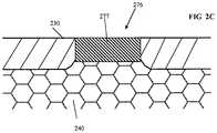
- the non-enzymatic membraneis also placed in contact with a top surface of the enzyme material so as to permit diffusion of the oxygen and glucose into the enzyme material to permit chemical interaction therein, while affording the solid tissue of the host an unreactive “buffer zone,” thereby isolating the host tissue from direct contact with the enzyme material.
- the response time (at a given oxygen level) of each sensor elementis selectable or controllable through control of one or more physical attributes of the non-enzyme membrane and/or its surrounding “spout” structure (e.g., base height, spout height, and/or non-enzyme membrane thickness).
- the outer membraneis comprised at least in part of a silicone rubber compound
- the non-enzyme membranecomprises an albumin-based compound
- a single parameter of those listed abovee.g., the spout height
- the sensor apparatusincludes one or more sensor elements capable of measuring blood glucose level both (i) within a prescribed range of response and (ii) within a prescribed time period.
- Each sensor elementincludes a non-enzymatic membrane element (e.g., including crosslinked albumin), the range of response (at a given oxygen level) of the sensor element(s) is selectable or controllable through control of base diameter and/or spout diameter, and the rate or timing of response (at a given oxygen level) of the sensor element(s) is selectable or controllable through control of base height and/or spout height.
- a non-enzymatic membrane elemente.g., including crosslinked albumin
- the sensor apparatusincludes: signal processing circuitry and at least one detector element in signal communication with the signal processing circuitry.
- the at least one detector elementincludes: a substantially enclosed cavity, the substantially enclosed cavity comprising at least one enzymatic substance, and at least one aperture in communication with the cavity; an electrolyte layer; at least one electrode disposed at least partly within or contacting the electrolyte layer; and a non-enzymatic membrane at least partly occluding the aperture, the non-enzymatic membrane comprising a material at least partly permeable to an analyte yet which does not exacerbate an FBR (including fibrous tissue growth).
- FBRfibrous tissue growth
- the non-enzymatic membranecomprises a crosslinked albumin-based material
- the at least one detector elementis configured to utilize chemical interaction between at least the analyte and the enzymatic substance to enable generation of an electrical signal at the electrode via the electrolyte layer, the electrical signal relating to a concentration of the analyte in a region external to the cavity and the membrane.
- a method of forming a sensor element for use on, inter alia, an implantable sensor apparatusincludes forming the aforementioned outer hydrophobic membrane of the sensor element using a molding process, such that the desired parameter value(s) is/are achieved (e.g., desired aperture placement and diameter), and disposing an enzymatic material within an interior cavity of the sensor element, as well as a non-enzymatic tissue-contacting layer over top of the enzymatic material and within the aperture.
- the outer membranecomprises a silicone rubber compound that can be molded according to the foregoing methodology, and the non-enzymatic tissue-contacting layer includes albumin.
- the albumin layeris in one implementation configured to mitigate excessive FBR.
- a method of configuring a sensor apparatus to achieve a desired level of performanceincludes one or more elements with permeable membranes, and the method includes configuring one or more parameters relating to the membrane(s) to achieve the desired level of performance.
- the level of performancerelates to a detection range of response of glucose concentration in the blood of a living being, and the one or more parameters comprise a diameter or an area associated with at least a portion of the permeable membrane(s), and/or its thickness.
- a membrane useful with an in vivo sensor apparatusis disclosed.
- the membraneis formed at least in part of a crosslinked albumin-based compound, and the membrane is specifically configured with respect to at least one parameter thereof (e.g., height relative to a base, thickness, and/or diameter, etc.) to produce a desired level of performance or response with respect to one or more substances (e.g., glucose in blood), such as rate of permeation of glucose through the membrane, or detectable range of concentrations of the enzyme.
- the albumin-based membraneis configured so as not to exacerbate an FBR after implantation of the host sensor apparatus.
- a sensor apparatus with heterogeneous sensor elementsis disclosed.
- the sensor apparatusis configured for (full) implantation in e.g., the solid tissue of a living being, and includes two or more sensor elements capable of measuring blood glucose level in at least one of: (i) different ranges of response, and/or (ii) different times or rates of response.
- each sensor elementincludes a non-enzymatic membrane element in contact with the solid tissue, and the range of response (at a given oxygen level) of each sensor element is selectable or controllable through control of one or more physical attributes of the membrane and/or its surrounding “spout” structure (e.g., base diameter and and/or spout diameter).
- the two or more sensor elementsutilize membranes having respective different ranges of response due to e.g., different physical diameters thereof.
- the different ranges of response to glucose levelat least partly overlap one another.
- the different ranges of response to glucose levelare substantially contiguous, but do not significantly overlap one another.
- the different ranges of response to glucose levelare neither contiguous or overlap one another; i.e., are separated by one or more ranges (e.g., those not of interest).
- each sensor elementincludes a non-enzymatic membrane element (e.g., an albumin-based membrane such as that referenced supra), and the time or rate of response (at a given oxygen and glucose level) of each sensor element is selectable or controllable through control of one or more physical attributes of the membrane and/or its surrounding “spout” structure (e.g., membrane thickness, and/or height of the spout above a base region).
- the two or more sensor elementsutilize non-enzyme membranes having respective different rates of response due to e.g., different physical diameters or other properties thereof.
- eight (8) sensor elementsare included on the sensor apparatus, two (2) of which are configured to measure glucose level within a first range of times, and two of which are configured to measure glucose level within a second range of times; the remaining four (4) sensor elements are used to measure oxygen concentration (i.e., are reference elements).
- the sensor apparatusincludes sensor elements having heterogeneity with respect to both range of response (concentration) and rate of response (rate of permeation).
- a sensor element configurationis disclosed.
- the sensor elementis used as part of an implantable sensor apparatus, and the configuration includes an enzyme-free outer layer or portion which prevents tissue of the host being from contacting immobilized underlying enzymes (e.g., glucose oxidase and catalase) within the sensor element when the sensor element is in vivo, thereby both (i) mitigating or eliminating a foreign body response (FBR) within the tissue due to lack of exposure to the enzymes or byproducts of the underlying reaction (e.g., peroxide), and (ii) ultimately enhancing operation and longevity of the sensor apparatus due to, inter alia, the aforementioned lack of FBR and the (excess) immobilized enzymes.
- immobilized underlying enzymese.g., glucose oxidase and catalase
- the enzyme-free outer layer or portioncomprises a soluble protein-based (e.g., albumin-based) material which is cured using a cross-linking agent, and which is configured so as not to encourage blood vessel growth into the membrane after implantation of the sensor element into a living host.
- a soluble protein-basede.g., albumin-based
- a method of mitigating foreign body response (FBR) associated with an implanted analyte detector elementincludes creating an enzyme-free buffer zone between a reactive enzymatic portion of the detector element using a non-enzymatic membrane or layer that is permeable to both the analyte (e.g., glucose) and oxygen.
- the enzymatic portioncomprises a mechanically stable matrix, such that the enzymes of the matrix are substantially immobilized and do not migrate outward toward the host's tissue through the non-enzymatic membrane or layer, but the analyte and oxygen from the tissue can migrate inward.
- the non-enzymatic membrane materialis selected so as to not exacerbate the FBR, thereby mitigating fibrous tissue formation and making subsequent explants of the detector element easier due to limited FBR-induced encapsulation.
- a method of controlling at least one operating characteristic of an oxygen-based blood analyte sensing elementincludes controlling at least one of a dimension of the aperture or the base so as to selectively control the diffusion of analyte and oxygen into the cavity, thereby causing the sensing element to exhibit the desired operating characteristic when operated.
- the analytecomprises glucose; the enzyme filling comprises glucose oxidase and catalase; and the desired operating characteristic comprises a range of analyte concentration that can be detected by the sensing element, and the at least one dimension comprises at least one of: (i) a diameter of the aperture, and/or (ii) a diameter of the base region.
- the analytecomprises glucose; the enzyme filling comprises glucose oxidase and catalase; and the desired operating characteristic comprises a time within which an analyte concentration can be detected by the sensing element, and the at least one dimension comprises at least one of: (i) a height of the aperture relative to a height of the base region.
- the elementincludes an enzyme-filled cavity with a base region, the cavity accessible via an aperture and an at least partly enzyme-free permeable membrane covering the aperture, and the method includes: selectively controlling the migration of at least an analyte into the cavity through the enzyme-free membrane; creating residual oxygen within the cavity; and selectively controlling the migration of at least portions of the residual oxygen to at least one electrode of the sensing element.
- the selective control of the migration of analyte and the selective control of the migration of oxygencooperate to cause the sensing element to exhibit a desired operating characteristic.
- the desired operating characteristiccomprises a range of glucose concentrations detectable by the sensing element, and the selectively controlling the migration of the glucose is accomplished at least in part by selectively choosing an area of the aperture.
- an analyte detection apparatusincludes: a substrate; at least one electrode disposed on or within the substrate, the at least one electrode comprising at least a terminal configured to enable electrical signals to be communicated from the electrode to a circuit; an electrolyte material in communication with at least a portion of the at least one electrode; a first membrane element in contact with at least a portion of the electrolyte material; a second membrane element comprising a cavity formed therein, and at least one aperture; an enzymatic material disposed within the cavity and configured to interact with the analyte and at least a portion of the oxygen entering the cavity via the aperture; and a non-enzymatic material configured to substantially occlude the aperture and frustrate migration of any enzymes from the enzymatic material outward to the tissue of the living host, yet permit diffusion of analyte and oxygen therethrough.
- a response characteristic of the analyte detection apparatusis controlled at least in part by a shape of the second
- the substratecomprises a ceramic material
- the first membranecomprises a polymeric material
- the second membrane elementcomprises a silicone rubber-based material
- the analytecomprises glucose
- the enzymatic materialcomprises glucose oxidase and catalase disposed in a crosslinked matrix
- the non-enzymatic materialcomprises albumin
- a dynamically variable sensor apparatusincludes: signal processing circuitry; and at least one first detector element and at least one second detector element each in signal communication with the signal processing circuitry.
- the at least one first and second detector elementseach comprise: a partly enclosed cavity, the cavity comprising at least one enzymatic substance, and at least one aperture in communication with the cavity, the aperture at least partly obscured with a non-enzyme yet permeable substance; an electrolyte layer; and at least one electrode disposed at least partly within or contacting the electrolyte layer; and the at least one first and second detector elements are each configured to utilize chemical interaction between at least the analyte and their respective enzymatic substance to enable generation of an electrical signal at their respective electrodes via their respective electrolyte layer, the electrical signal relating to a concentration of the analyte in a region external to their respective cavities.
- At least one of (i) a shape or dimension of the aperture, (ii) a thickness of the non-enzyme yet permeable substance, and/or (iii) a shape or dimension of the cavity, for the at least one first detector elementis different from that for the second at least one detector element, thereby enabling the at least one first detector element and the at least one second detector element to have a different operational characteristic from the other.
- a method of mitigating a foreign body response (FBR) within a living being while monitoring blood glucose level using an implanted sensor apparatusincludes: allowing at least oxygen molecules and glucose molecules from the living being's blood to permeate through a non-enzymatic layer or membrane to an enzyme-containing material with which the oxygen molecules and glucose molecules can chemically interact, the chemical interaction enabling the monitoring; and at least mitigating egress of enzymes within the enzyme-containing material outward through the layer or membrane.
- the non-enzymatic materialcomprises a protein-based (e.g., albumin) substance which is chemically crosslinked, and which does not encourage blood vessel growth into its thickness.
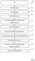
- a method of manufacturing an analyte detector elementincludes: providing a substrate; embedding at least one electrode within the substrate; disposing an electrolyte over at least a portion of the substrate, including at least a portion of the electrode; forming an inner membrane over at least a portion of the electrolyte; forming an outer membrane having an aperture formed therein, and disposing the outer membrane over the inner membrane such that the inner and outer membranes form a cavity; disposing an enzyme matrix material into the cavity such that it at least contacts the inner membrane and aperture; and forming a layer of non-enzymatic material within the aperture such that it at least partly contacts the enzyme matrix material.
- the outer and inner membranescomprise an elastomeric material (e.g., silicone rubber), and the outer membrane is adhered (e.g., via a room temperature vulcanizing (RTV) adhesive) to the inner membrane in order to create the cavity.
- RTVroom temperature vulcanizing
- the enzyme matrixis then introduced into the cavity via the aperture; e.g., the matrix is substantially liquefied, and is poured or piped into the cavity so as to substantially fill the cavity, and exclude air therefrom, while also maintaining the aperture region entirely enzyme-free.
- the enzyme matrixis then cured (e.g., chemically crosslinked), and subsequently the non-enzymatic material (also in a substantially liquefied or flowable form) is poured or piped into the top portion of the cavity via the aperture (i.e., atop the cured enzyme matrix), and subsequently chemically crosslinked as well.
- FIG. 1is a front perspective view of one exemplary embodiment of a fully implantable sensor apparatus according to the present disclosure.
- FIGS. 1A-1Care top, bottom, and side elevation views, respectively, of the exemplary sensor apparatus of FIG. 1 .
- FIG. 2is a side cross-sectional view of one exemplary detector element of a detector array in a fully implantable sensor apparatus according to the present disclosure.
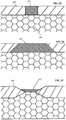
- FIG. 2Ais a side cross-sectional view of one exemplary spout region (outer non-enzyme membrane removed) of a detector element of a detector array in a fully implantable sensor apparatus according to one embodiment of the present disclosure.
- FIG. 2Bis a graphical representation of top elevation views of a variety of different exemplary embodiments of sensor membrane apertures according to the present disclosure.
- FIGS. 2C-2Fare side cross-sectional views of respective ones of a variety of different exemplary embodiments of sensor membrane apertures according to the present disclosure.
- FIG. 3is a top elevation view of another exemplary embodiment of the sensor apparatus of present disclosure, wherein multiple sensor/reference pairs with at least partly differing glucose sensing ranges are used on a common device.
- FIG. 4is a logical flow diagram of one embodiment of a method of manufacturing a sensor element according to the present disclosure.
- the terms “detector” and “sensor”refer without limitation to a device that generates, or can be made to generate, a signal indicative of a measured parameter, such as the concentration of an analyte (e.g., glucose or oxygen).
- a devicemay be based on electrochemical, electrical, optical, mechanical, thermal, or other principles as generally known in the art.
- Such a devicemay consist of one or more components, including for example, one, two, three, or four electrodes, and may further incorporate immobilized enzymes or other biological or physical components, such as membranes, to provide or enhance sensitivity or specificity for the analyte.
- membranerefers without limitation to a substance, layer or element configured to have at least one desired property relative to the aforementioned analyte, such as e.g., a permeability to a given type of analyte or sub stance.
- enzyme free and non-enzymaticinclude, without limitation, materials that are completely enzyme-free, and materials that are substantially enzyme free (e.g., may have a small percentage of residual or unintentional enzymes).
- topmerely connote, without limitation, a relative position or geometry of one component to another, and in no way connote an absolute frame of reference or any required orientation.
- a “top” portion of a componentmay actually reside below a “bottom” portion when the component is mounted to another device (e.g., host sensor).
- the present disclosureprovides improved enzymatic detectors and associated membrane apparatus, and associated methods of manufacturing and use, such as within a fully implantable sensor apparatus of the type described in U.S. patent application Ser. No. 14/982,346 entitled “Implantable Sensor Apparatus and Methods,” previously incorporated by reference herein.
- the apparatus and methods of the disclosureenable, inter alia, substantially continuous, long-term and accurate monitoring of blood glucose levels in living beings using the aforementioned implantable sensor apparatus, without the need for prior art “finger sticks,” transcutaneous apparatus worn on external surfaces of the body, or intravenous devices, each having their own disabilities as previously described.
- the present disclosuredescribes a novel sensor (detector) element configuration, including use of selectively configured membrane elements and enzyme region shapes, which enable accurate detection of blood glucose level within the solid tissue of the host for extended periods of time, and within desired ranges and/or rates of response.
- the performance of the detector elementsmay be controlled through variation of one or more physical parameters of the membrane elements (e.g., dimensions, shapes, etc.), including an access or “spout” region, so as to allow for precise measurement of the target analyte, while also maintaining isolation between the host's tissue and the underlying enzymes and also potentially between the host tissue and reaction byproducts used in the sensor element, thereby advantageously minimizing foreign body response (FBR) to the device while implanted, particularly in the region(s) where sensing of the target analyte is performed.
- FBRforeign body response
- an enzyme-free layer or membraneis formed within the spout region and used in conjunction with a substantially immobilized underlying enzyme material, such that the analyte (e.g., glucose molecules) and oxygen molecules can permeate through to the enzyme region, but the enzymes (e.g., catalase and glucose oxidase) do not permeate outward.
- the spout region of the sensor elementis also advantageously maintained substantially enzyme-free during manufacturing, and a reasonably tight “seal” is formed around a periphery of the enzyme-free layer or membrane after curing (and the enzyme-free layer may even be bonded to its surrounding structure), such that undesired enzyme migration or contact with the living host's tissue are avoided.
- the disclosed configurationadvantageously does not encourage blood vessel ingrowth, which inter alia, enables accurate sensor apparatus operation during periods of extended implantation. By not encouraging such ingrowth, otherwise unstable/unpredictable modulation of FBR to the extent required to encourage blood vessel ingrowth is wholly avoided. In one variant, such ingrowth is frustrated (or not encouraged) through selective control of pore sizes within the non-enzymatic layer.
- Control of response range and/or ratealso permits easy “customization” of sensor elements, whether on a per-element or per-sensor apparatus basis.
- the techniques of the present disclosureallow for ready construction of an implantable sensor apparatus having multiple heterogeneous detector elements with respective multiple ranges of sensitivity and/or rates of detection, thereby extending the dynamic range of the sensor apparatus (both in terms of analyte concentration and/or time, as desired).
- the various heterogeneous detector elementscan be selectively switched on/off (even while the sensor apparatus is in vivo), so as to, e.g., accommodate “on the fly” changes to blood glucose concentration occurring within the host, or to maintain the detector elements within a known or desirable range of accuracy or sensitivity.
- FIGS. 1-1Cone exemplary embodiment of a sensor apparatus useful with various aspects of the present disclosure is shown and described.
- the exemplary sensor apparatus 100comprises a somewhat planar housing structure 102 with a sensing region 104 disposed on one side thereof (i.e., a top face 102 a ).
- the exemplary substantially planar shape of the housing 102provides mechanical stability for the sensor apparatus 100 after implantation, thereby helping to preserve the orientation of the apparatus 100 (e.g., with sensing region 104 facing away from the epidermis and toward the proximate fascial layer), resisting rotation around its longitudinal axis 108 , and translation, or rotation about its transverse axis 110 , which might otherwise be caused by e.g., normal patient ambulation or motion, sudden accelerations or decelerations (due to e.g., automobile accidents, operation of high-performance vehicles such as aircraft), or other events or conditions.
- the present disclosurecontemplates sensor apparatus of shapes and/or sizes other than that of the exemplary apparatus 100 , including use of means to maintain the desired orientation and position such as e.g., protruding tabs, “anchoring” the sensor apparatus to surrounding physiological structures such as the fascial layer by means of sutures or the like, attached tissue ingrowth structures, and so forth.
- the exemplary sensor apparatus of FIGS. 1-1Cfurther includes a detector array 104 comprising a plurality of individual detectors elements 106 on the top face 102 a of the sensor apparatus housing 100 .
- the detector array 104 of the present inventionincludes eight (8) detector elements 106 with associated membranes (not shown) disposed on a detector substrate 112 (e.g. ceramic disk), which function as a group.
- the detector elements 106 in the illustrated embodimentcomprise a plurality of primary detectors including associated membranes containing glucose oxidase and catalase to measure glucose-dependent oxygen levels, and a plurality of secondary detectors including associated membranes without bonded enzymes to measure background oxygen levels.
- a signal-processing elementmeasures the current difference between the glucose-dependent oxygen current and the background oxygen current, to produce a glucose-dependent difference current.
- the exemplary sensor apparatus 100 of the present disclosureutilizes an “oxygen-sensing differential measurement,” by comparison of the glucose-dependent oxygen signal to the background oxygen signal that produces, upon further signal processing, a continuous real-time blood glucose concentration measurement. It will be appreciated, however, that the methods and apparatus described herein are in no way limited to such “differential” schemes.
- the exemplary sensor apparatus of FIGS. 1-1Calso includes a plurality (three in this instance) of tabs or anchor apparatus 113 disposed substantially peripheral on the apparatus housing.
- These anchor apparatusprovide the implanting surgeon with the opportunity to anchor the apparatus to the anatomy of the living subject, so as to frustrate translation and/or rotation of the sensor apparatus 200 within the subject immediately after implantation but before any body response (e.g., FBR) of the subject has a chance to immobilize (such as via encapsulation) the sensor apparatus.
- FBRbody response
- each type of detector elements 106is included (i.e., four primary, and 4 secondary), although it will be appreciated that any number of detector elements can be used consistent with the disclosure (including in pairs, or where one primary or secondary detector is used in conjunction with two or more of the other type of detector). Numerous permutations are possible, all considered within the scope of the present disclosure.
- the exemplary detector elements 106are of the enzyme-electrode type (some utilizing membranes containing immobilized glucose oxidase and catalase), such as those exemplary embodiments described herein, and/or those set forth in U.S. Pat. No. 4,484,987 to Gough, entitled “Method And Membrane Applicable To Implantable Sensor;” U.S. Pat. No. 4,671,288 to Gough, entitled “Electrochemical Cell Sensor For Continuous Short-Term Use In Tissues And Blood;” U.S. Pat. No. 4,650,547 to Gough, entitled “Method And Membrane Applicable To Implantable Sensor;” U.S. Pat. No.
- the type and operation of the sensor apparatus 100may vary; i.e., other types of detector elements/sensor apparatus, configurations, and signal processing techniques thereof may be used consistent with the various aspects of the present disclosure, including, for example, signal processing techniques based on various combinations of signals from individual elements in the otherwise spatially-defined sensing elements pairs.
- the exemplary detector elements 106utilize the following two-step chemical reaction catalyzed by glucose oxidase and catalase to detect glucose, as described in Armour et al. (Diabetes 39, 1519-1526 (1990)): Glucose+O 2 +H 2 O Gluconate+H 2 O 2 (Glucose Oxidase) H 2 O 2 1 ⁇ 2O 2 +H 2 O (Catalase) Glucose+1 ⁇ 2O 2 Gluconate (Net)
- the two enzymes(glucose oxidase and catalase) are entrapped or more preferably immobilized within a gel matrix (discussed infra) that is e.g., crosslinked for mechanical and chemical stability, and which is in operative contact with a working electrode to electrochemically detect oxygen.
- a chemical or other crosslinking techniquecan be used consistent with the disclosure to immobilize the enzymes
- other approaches for immobilization and/or mechanical stabilization of the enzyme matrix (primary detectors) and/or non-enzyme matrix (secondary detectors)may also be used, whether alone or in combination with the foregoing.
- a non-cross-linked (yet mechanically stable) gelcould be used.
- a porifera or other sponge/sponge-like structurecould be used (e.g., with the enzyme disposed within the pores or ostia of the structure for mechanical stability).
- a ladder, scaffold, or three-dimensional mesh structurecould be used to support the enzymatic material.
- glucose and ambient oxygendiffuse into the gel matrix and encounter the enzymes, the above reactions occur, and the oxygen that is not consumed in the process is detected by the working or primary electrode.
- an exemplary individual (primary) detector element 106is shown associated with detector substrate 214 (e.g. a ceramic substrate), and generally comprises a plurality of membranes and/or layers, including e.g., the insulating layer 260 , and electrolyte layer 250 , an enzymatic gel matrix of the type described above 240 , an inner membrane 220 , an exterior membrane shell 230 , and a non-enzymatic membrane 277 .
- Such membranes and layersare associated with the structure of individual detector elements, although certain membrane layers can be disposed in a continuous fashion across the entire detector array surface or portions thereof that include multiple detectors, such as for economies of scale (e.g., when multiple detectors are fabricated simultaneously), or for maintaining consistency between the individual detector elements by virtue of making their constituent components as identical as possible.
- the exemplary sensor apparatus 100includes both primary (enzymatic) and secondary (non-enzymatic) detector elements; while FIG. 2 illustrates one embodiment of the former, the latter is in the exemplary embodiment generally similar in structure, with the exception that the enzymatic matrix 240 is replaced with a non-enzymatic matrix or other structure; i.e., in the case of a glucose-sensitive primary detector, it does not include the glucose oxidase and catalase described elsewhere herein. It will be appreciated, however, that the construction of primary and secondary detector elements need not be substantially similar, and in fact may differ significantly in construction so long as the desired performance attributes are maintained.
- the detector element 106further comprises a working electrode 217 in operative contact by means of electrolyte layer 250 with a counter electrode 219 and a reference electrode 218 , and their associated feedthroughs 280 (details of the exemplary feedthroughs 280 are described in U.S. Pat. No. 8,763,245 to Lucisano et al. entitled “Hermetic feedthrough assembly for ceramic body,” previously incorporated by reference herein).
- the working electrode 217comprises an oxygen-detecting catalytic surface producing a glucose-modulated, oxygen-dependent current (discussed infra)
- reference electrode 218comprises an electrochemical potential reference contact to electrolyte layer 250
- counter electrode 219is operably connected by means of electrolyte layer 250 to the working electrode 217 and reference electrode 218 .
- An electrical potentiostat circuit(not shown) is coupled to the electrodes 217 , 218 , and 219 to maintain a fixed potential between the working and reference electrode by passing current between the working and counter electrodes while preferably maintaining the reference electrode at high impedance.
- Such potentiostat circuitryis well known in the art (for an example, see U.S. Pat. No. 4,703,756 to Gough et al. entitled “Complete glucose monitoring system with an implantable, telemetered sensor module,” incorporated herein by reference in its entirety).
- each of the membranes disclosed hereinis not particularly limited, as long as the desired permeability properties are achieved.
- particular requirements for sensor response time, glucose concentration detection range, and/or reduction of antibody response (e.g., FBR)may impose limits on the allowable membrane thickness.
- Membrane thicknesscan be, for example, about 1 micron to about 1000 microns, or more particularly, about 10 microns to about 500 microns, or more particularly about 25 microns to about 250 microns, or more particularly about 25 microns to about 75 microns.
- Very thin membrane layers, particularly those less than about 10 micronsmay require mechanical support to be provided in the form of a backing membrane, which may be a porous, relatively inert structure.
- the electrolyte layer 250comprises, in the illustrated embodiment, a layer of hydrophilic electrolyte material which is in direct contact with the working electrode(s) 217 , reference electrode(s) 218 and counter electrode(s) 219 .
- materials for constructing the hydrophilic electrolyte layer 250include salt-containing gels comprising polyacrylamide, poly(ethylene oxide) poly(hydroxyethylmethacrylate) and its derivatives, and other hydrophilic polymers and copolymers, in both crosslinked and non-crosslinked form.
- salt-containing gelscomprising polyacrylamide, poly(ethylene oxide) poly(hydroxyethylmethacrylate) and its derivatives, and other hydrophilic polymers and copolymers, in both crosslinked and non-crosslinked form.
- the enzymatic material 240comprises a crosslinked gel of hydrophilic material including enzymes (e.g., glucose oxidase and catalase) immobilized within the gel matrix, including a buffer agent and small quantities of a chemical cross-linking agent.
- the hydrophilic material 240is permeable to both a large molecule component (e.g. glucose) and a small molecule component (e.g. oxygen).
- specific materials useful for preparing the enzymatic material 240include, in addition to an enzyme component, polyacrylamide gels, glutaraldehyde-crosslinked collagen or albumin, poly(hydroxyethylmethacrylate) and its derivatives, and other hydrophilic polymers and copolymers, in combination with the desired enzyme or enzymes.
- the enzymatic material 240can similarly be constructed by crosslinking glucose oxidase or other enzymes with chemical crosslinking reagents, without incorporating additional polymers.
- the enzymatic material 240is in operative contact with the working electrode 217 through the inner membrane 220 and the electrolyte layer 250 to allow for the electrochemical detection of oxygen at the working electrode 217 modulated by the two-step chemical reaction catalyzed by glucose oxidase and catalase discussed above.
- glucose and ambient oxygendiffuse into the enzymatic material 240 , they encounter the resident enzymes (glucose oxidase and catalase) and react therewith; the oxygen that is not consumed in the reaction(s) diffuses through the inner membrane 220 and is detected at the working electrode 217 to yield a glucose-dependent oxygen signal.
- a hydrophobic materialis utilized for inner membrane 220 , which is shown in FIG. 2 as being disposed over the electrolyte layer 250 .
- the hydrophobic materialis impermeable to the larger or less soluble molecule component (e.g. glucose) but permeable to the smaller or more soluble molecule component (e.g. oxygen).
- materials useful for preparing hydrophobic layersinclude organosilicon polymers, such as polydimethylsiloxane (PDMS) and derivatives thereof, polymers of tetrafluoroethylene, ethylene tetrafluoroethylene, or fluorochloro analogs alone or as copolymers with ethylene or propylene, polyethylene, polypropylene, cellulose acetate, and other oxygen-permeable polymeric materials.
- organosilicon polymerssuch as polydimethylsiloxane (PDMS) and derivatives thereof, polymers of tetrafluoroethylene, ethylene tetrafluoroethylene, or fluorochloro analogs alone or as copolymers with ethylene or propylene, polyethylene, polypropylene, cellulose acetate, and other oxygen-permeable polymeric materials.
- the inner membrane 220can also be a continuous layer across the entire detector array surface, and thus be a single common layer utilized by all detectors in the detector array. It is noted that the inner membrane 220 , inter alia, protects the working electrode 217 , reference electrode 218 and counter electrode 219 from drift in sensitivity due to contact with certain confounding phenomena (e.g. electrode “poisoning”), but the working electrode 217 will nonetheless be arranged sufficiently close to the enzymatic material to enable detection of oxygen levels therein.
- certain confounding phenomenae.g. electrode “poisoning”
- the (hydrophobic) outer membrane shell 230is disposed over at least a portion of the enzymatic material 240 (forming a cavity 271 within which the material 240 is contained), and is further configured to include an aperture within a “spout” region 270 (discussed in greater detail infra).
- the membrane shell 230is separately provided and adhesively bonded to the inner membrane 220 , although it is also contemplated that the inner membrane 220 and the membrane shell 230 can be coextensive and therefore be disposed as one continuous membrane layer in which outer membrane shell 230 and inner membrane 220 are of the same uniform thickness of membrane across the individual detector and array.
- inner membrane 220 and membrane shell 230are disposed in a manner that creates discrete three-dimensional regions having different thicknesses on the detector substrate 214 , which can be utilized to create tissue anti-migration elements used to achieve stability of location and prevention of device migration away from its original implant location.
- the hydrophobic componentmay be dispersed as small domains in a continuous phase of the hydrophilic material.
- Various other construction details of the hydrophobic component dispersed as small domains in a continuous phase of hydrophilic materialare described in U.S. Pat. Nos. 4,484,987 and 4,890,620, each incorporated herein by reference in its entirety.
- the exemplary sensor apparatusis made biocompatible to allow for long term implantation into biological tissue.
- all membrane structures that are in direct contact with the surrounding biological materialare biocompatible and not problematically immunogenic.
- the membrane materials disclosed herein that are in direct contact with tissuei.e., the non-enzymatic membrane element 277 and the outer membrane (shell) 230 are generally known to be biocompatible and suitable for long term implantation.
- all or discrete regions of the sensormay include one or more additional coatings or membrane layers of non-erodible biocompatible material, which may be included to ensure that the immunogenic potential of all exposed materials remains suitably low.
- a single spout region 270 of the detector element 106forms a small opening or aperture 276 through the membrane shell 230 to constrain the available surface area of hydrophilic enzymatic material 240 exposed for diffusionally accepting the solute of interest (e.g. glucose) from solution.
- solute of intereste.g. glucose
- one or more spout regions (and or apertures within a spout region)can exist per detector element.
- spout region 270aids in controlling the rate of entry of the solute of interest (e.g. glucose) into enzymatic material 240 , and thus impacts the effective operational permeability ratio of the enzymatic material 240 .
- solute of intereste.g. glucose
- Such permeability ratiocan be expressed as the maximum detectable ratio of glucose to oxygen concentration of an enzymatic glucose sensor, where such a sensor is based on the detection of oxygen unconsumed by the enzyme reaction, and after taking into account the effects of external mass transfer conditions and the enzyme reaction stoichiometry.
- the membranes of the exemplary detector element described hereinare characterized by a permeability ratio of oxygen to glucose of about 200 to about 1 in units of (mg/dl glucose) per (mmHg oxygen). Note that while this measure of permeability ratio utilizes units of a glucose concentration to an oxygen concentration, it is nevertheless a measure of the ratio of oxygen to glucose permeability of the membrane.
- the exemplary spout 270is formed out of the hydrophobic material of the membrane shell 230 without bonded enzymes (e.g., silicone rubber) and advantageously includes a non-enzymatic outer layer or membrane 277 to, inter alia, prevent direct contact of the immobilized enzymes in the enzymatic material 240 with the surrounding tissue, thereby eliminating and/or reducing antibody response (e.g., FBR), encapsulation, and/or other deleterious factors.
- bonded enzymese.g., silicone rubber
- the non-enzymatic membrane 277is further constructed (i.e., with a substantially planar crosslinked biocompatible matrix possessing pores substantially smaller than those required to accommodate blood vessel ingrowth, but large enough to accommodate diffusion of solutes of interest) so as to frustrate or mitigate blood vessel formation therein.
- Suitable poresinclude those with an effective diameter ranging from approximately 10 angstroms up to approximately 10 microns.
- a salient feature of the sensor element of the exemplary embodimenti.e., the combination of (i) an enzyme-free biocompatible outer membrane 277 , (ii) maintenance of the spout region substantially free of enzyme material during manufacture (see discussion of manufacturing methods below), (iii) use of a non-porous crosslinked structure for the membrane 277 , and (iv) use of a biocompatible material (e.g., silicone rubber) for the outer membrane shell 230 , dramatically reduces the level of FBR of the host while the device is implanted, thereby allowing for both longer implantation (due to, inter alia, the reduced level of FBR not interfering with sensor operation) and easier explants of the device, as compared to e.g., peroxide-based sensors without such features.
- a biocompatible materiale.g., silicone rubber
- the inner hydrophobic membrane 220further provides additional insulation of the host tissue in the region of the detector 106 against any electrical potentials which may be present with in the sensor element, thereby further aiding in mitigating FBR.
- materials for constructing the membrane layer 277include gels comprising proteins such as albumin and collagen, as well as non-proteinaceous polymers such as polyacrylamide, poly(ethylene oxide) poly(hydroxyethylmethacrylate) and its derivatives, and other hydrophilic polymers and copolymers, in both crosslinked and non-crosslinked form.
- the spout aperture diameter 272in part controls the effective operational membrane permeability ratio.
- the aperture diameteris correlated to the range of concentration the target analyte (e.g., glucose) that can be detected by the detector element.
- a larger aperture diametercorresponds to a lower permeability ratio of oxygen to glucose, and hence a greater sensitivity to a given concentration of glucose within the tissue proximate the aperture (and therefore a lower minimum concentration that can be accurately detected).
- the detectorwill “saturate” more rapidly at a given oxygen concentration, and hence the upper bound of detection is similarly reduced.
- a smaller diameter aperturecorresponds to an increased permeability ratio, and hence a higher minimum effective sensitivity (and corresponding higher maximum detectable concentration before saturation is reached).
- the aperture 276 of the spout region 270may be virtually any geometric shape so long as the desired permeability ratio is achieved, such as, for example, round, oval, elliptical, rectangular, triangular, star shaped, square, polygonal, and the like (see FIG. 2B ), or even irregular, although round (circular) apertures are generally preferred because such shapes are more amenable to manufacturing; and (ii) diameter is straightforwardly related to area, and the present disclosure contemplates that area may be a useful measure of “spout size” as it relates to adjusting the operational characteristics of the detector element in place of diameter.
- the diameter 273 of the base region(i.e., that region underlying the outer membrane 230 ; see FIG. 2 ) can affect operation of the detector, including specifically the range of concentrations of analyte that can be measured.
- the present disclosurecontemplates use of one or more of the foregoing dimensional parameters to configure or optimize the operation of the detector element 106 for a prescribed application.
- the outer (non-enzymatic) membrane layer 277can be formed in any number of different ways.
- the non-enzymatic layer 277is in effect “pour filled” into the aperture 276 of the outer housing membrane 230 atop the (crosslinked) enzymatic membrane matrix 240 .
- the present disclosurecontemplates other techniques for formation, including for example provision of a pre-formed membrane 277 which is inserted into the aperture in operative contact with the enzyme material 240 , or even chemical or other treatments of the upper surface of enzyme material 240 , including various de-immunizing treatments.
- the outer membrane layer 277comprises a crosslinked albumin, which exhibits the aforementioned desirable properties of (i) lack of FBR-inducing enzymes, (ii) non-porosity, and (iii) electrical insulation.
- the exemplary albumin material used for the membrane layer 277is biocompatible; in the present context (a tissue-located implant), the term ‘biocompatible’ as applied to the membrane layer 277 indicates that the material itself does not significantly exacerbate the FBR which is otherwise expected to occur with any implant. So, the amount/degree of fibrous tissue formation that results from the FBR (which nonetheless occurs due to natural body processes) is advantageously minimized, compared to what might be obtained with another less-biocompatible material.
- the hydrophilic albumin of the outer membrane 277is in direct contact with the (hydrophilic) tissue of the host, thereby advantageously providing a “like-to-like” interface, which also contributes to the stability of the detector elements over time due to, among other things, the aforementioned non-exacerbation of FBR or other host responses.
- the exemplary membrane layer 277 described hereinby virtue of its non-exacerbation of FBR in the host (e.g., through use of a biocompatible material such as crosslinked albumin), further results in mitigation of the formation of significant fibrous tissue response, which could otherwise interfere with optimal operation of the sensor detector elements or reduce their accuracy due to, inter alia, reduced blood vessel density in the fibrous tissue. So, in effect, the non-exacerbation of FBR and non-encouragement of blood vessel ingrowth into the membrane layer 277 by the exemplary embodiment herein actually (and somewhat counter-intuitively) stabilizes blood perfusion and blood glucose delivery to the detector elements, and avoids having to second-guess the largely unpredictable modulation process, especially over longer periods of implantation.
- a biocompatible materialsuch as crosslinked albumin
- biostable polymers suitable as outer (housing) membrane materialsinclude, for example, hydrophilic polyurethanes, silicones, poly(hydroxyethylmethacrylate)s, polyesters, polyalkyl oxides (polyethylene oxide), polyvinyl alcohols, and polyethylene glycols and polyvinyl pyrrolidone. See, inter alia, U.S. Patent Application Publication No. 2013/0197332 previously incorporated herein, for a discussion of other various outer membrane materials.
- the “vertical” spout/aperture profilecan take on many forms as dictated by a given application. See e.g., FIGS. 2C-2F , wherein several exemplary configurations (shown in cross-section) of apertures and enzyme material 240 are shown.
- the configuration of the apertureincluding its placement relative to other components within the detector element (including outer membrane 230 , inner membrane 220 , etc.), can affect the operation of the detector element.
- the present disclosurecontemplates that a rounded or smoothed and progressively narrowing aperture/spout shape (see FIG. 2C ) as one embodiment.
- a tapered or chamfered aperturemay be useful in certain circumstances.
- the “taper up” embodiment of FIG. 2Eprovides an added advantage relating to mechanical stability; i.e., the taper of the non-enzymatic membrane 277 and sidewalls of the aperture 276 cooperate to retain the membrane 277 (once cured) in place, and resist dislocation or movement potentially resulting from e.g., thermal expansion of the underlying enzyme matrix 240 , or interaction between the outer surface of the membrane 277 and the host tissue/encapsulation FBR which might tend to draw the membrane 277 out of the aperture 276 .
- other shapesmay similarly be used to provide such mechanical stability, such as e.g., an inverted “T” shape (not shown).
- a “rounded edge” or bull-nosed configuration of the aperturemay be useful.
- these various vertical aperture/spout profilesmay further be combined with one or more of the “horizontal” planar aperture shapes shown in FIG. 2B (or yet others) in order to achieve the desired performance attributes.
- the thickness of the non-enzyme layer or membrane 277may also be varied (as can other properties of the non-enzymatic membrane 277 , such as density or permeability) so as to effect the desired rate of permeation of the analyte and any associated coreactant(s) (e.g., glucose and oxygen) through the membrane, and also to frustrate or control blood vessel growth into the membrane 277 .
- the membrane 277need not have a consistent shape or thickness; e.g., it may have thicker or narrower regions (which may or may not be symmetrical), such as to create regions of e.g., greater or lesser permeation relative to the underlying enzyme-containing matrix 240 .
- the edges of the membrane 277are made thinner than the central portion, such that more analyte/oxygen permeates through the outer regions per unit time, and hence diffuses to the outer regions of the matrix 240 (i.e., those which are not directly under or proximate to the aperture 276 ). Hence, a more “even burn” of enzyme material is achieved.
- the “fill level” of enzyme material 240 relative to the spout/aperturecan be varied.
- the top of such enzymatic material 240is roughly coincident with the height of the bottom of the aperture 276 .
- the foregoing variation in fill levelmust, however, be consistent with the requirement that at least a portion of the outer (non-enzyme) layer or membrane 277 generally must be in physical or chemical “contact” with the underlying enzyme material 240 (absent any interposed material or vehicle) so as to permit permeation of the analyte(s) (e.g., glucose, and free oxygen) into the enzyme material 240 .
- the analyte(s)e.g., glucose, and free oxygen
- Such “chemical contact”may take various forms, including direct physical contact, indirect contact via an interposed layer of material or fluid (such as to promote binding of the outer membrane 277 to the matrix 240 ) which does not substantially mitigate permeation, or yet other ways.
- the outer membrane 277may be directly bonded or attached to the underlying matrix (whether enzymatic, such as in the primary detector elements, or non-enzymatic, such as in the secondary detector elements).
- enzymaticsuch as in the primary detector elements, or non-enzymatic, such as in the secondary detector elements.
- crosslinked albuminis used in the outer membrane 277 , and is bonded to the underlying crosslinked albumin-containing enzymatic matrix 240 , so as to promote inter alia, constant and complete glucose and oxygen molecule migration during operation.
- the direct bonding of the two cited membrane layershelps to ensure a stable mechanical structure of the membrane assembly, a prerequisite in ensuring stable, predictable sensor response characteristics.
- the two layersare bonded via a chemical crosslinking agent such as glutaraldehyde, which, for example, when the layers comprise proteinaceous materials, promotes chemical bonding between the layers as well as crosslinking within each layer.
- a chemical crosslinking agentsuch as glutaraldehyde, which, for example, when the layers comprise proteinaceous materials, promotes chemical bonding between the layers as well as crosslinking within each layer.
- the outer membrane layer 277may also be (chemically) bonded to the outer silicone membrane shell 230 such as at the interface between the outer edge of the membrane layer 277 and the inner periphery of the aperture 276 .
- This approachcan help further protect against any migration of the enzymes in the matrix 240 outward toward the host tissue, thereby avoiding any exposure thereof (and possible further FBR to the enzyme(s)).
- the exemplary spout region 270is filled or layered with an additional non-enzyme material or membrane 277 (such as to reduce the immunogenic potential of the enzymatic material 240 ), such layer or membrane 277 may not be required in certain cases.
- an additional non-enzyme material or membrane 277such as to reduce the immunogenic potential of the enzymatic material 240
- such layer or membrane 277may not be required in certain cases.
- a given detectordoes not utilize any enzymatic material (or uses an enzymatic material that produces limited if any FBR in the host tissue, it may be feasible to eliminate the outer non-enzymatic layer).
- the spout aperture(s) 276has a comparatively small diameter, such as where a plurality of small apertures 276 are used in place of a single larger aperture, direct contact surface area with host tissue may be quite small and spatially distributed, thereby potentially obviating the need for the “buffer” membrane 277 .
- a spatial gradient in enzyme concentration within the enzyme materialcan be employed, such that e.g., the concentration is reduced proximate the host solid tissue, thereby ostensibly mitigating FBR due to irritation by the enzymes, transient peroxides, etc.
- a chemical treatment applied during manufacturingcould be employed to “de-immunize” an exposed surface of membrane material 240 , obviating the need for the buffer membrane 277 .
- the detector array 104includes detector elements 106 with different spout (aperture) diameters and/or other physical characteristics; e.g., one detector or set of detectors with larger spout diameters and/or heights, and another detector/set with smaller spout diameters and/or heights. Having multiple detector elements 106 with such different physical characteristics (and hence operating characteristics) is beneficial for any number of reasons, including maintaining a broader desired sensor response range.
- a detector or set of detectors with e.g., a common, finite range of detectionmay be “over-ranged” or “under-ranged” such that it/they are incapable of accurately detecting the concentration through such a broad range of levels.
- twelve (12) sensor elementsare included on the sensor apparatus 300 , two (2) of which 306 a are configured to measure glucose level within a first response range, two of which 306 c are configured to measure glucose level within a second (at least partly differing) response range, and two of which 306 e are configured to measure glucose level within a third range which is at least partly different from the first and second ranges.
- the remaining six (6) sensor elements 306 b , 306 d , 306 fare used to measure oxygen concentration (i.e., are reference elements).
- another exemplary embodiment of the sensor apparatus described hereinmay include either or both of: (i) multiple detector elements with respective “staggered” ranges/rates of detection operating in parallel (as in the apparatus of FIG. 3 ), and/or (ii) multiple detector elements with respective “staggered” ranges/rates of detection that are selectively switched on/off in response to, e.g., the analyte concentration reaching a prescribed upper or lower threshold.
- the sensor apparatus 300includes two or more sets of detector elements 306 having different ranges of detection, and associated control logic such that the output of the various detector elements can be selectively utilized while the apparatus 300 is implanted in vivo.
- each detector elementincludes a pre-designated upper and lower threshold value for analyte concentration sensitivity, such that operation of the particular detector element outside of those bounds is less desirable (or even inoperable).
- the detector physical attributese.g., aperture diameter, base height, etc.
- the detector physical attributese.g., aperture diameter, base height, etc.
- the supporting circuitry of the sensor apparatusis configured in one variant to: (i) determine a trend or slope of analyte concentration, and (ii) a proximity to a given threshold for a given detector element (or set of elements), such that the circuitry can “hand off” from one detector element/set (e.g., with a first operational range or sensitivity) to a second element/set with a contiguous or overlapping range or sensitivity), thereby extending the dynamic range of the device as a whole.
- the aforementioned upper/lower thresholds or boundscan be selected such that the aforementioned “sweet spot” of the particular detector element is primarily used, with handoff to another element/set occurring before significant degradation of performance occurs.
- the upper and lower thresholds of a first sensor apparatus 300 with say six (6) heterogeneous, staggered sets of working and reference detectorscan be adjusted to “stitch together” the same dynamic range of a similar homogenous detector sensor apparatus (i.e., four sets of identical detector elements, such as the apparatus 100 of FIG. 1 ), yet with increased accuracy throughout the range, since each of the constituent detector elements in the heterogeneous apparatus 300 are each operating only in their “sweet spot” before handing off to the next detector element.
- thresholds or boundscan be selected independent of one another; and/or (ii) can be set dynamically while the apparatus 300 is implanted.
- operational detector elementsare continuously or periodically monitored to confirm accuracy, and/or detect any degradation of performance (e.g., due to equipment degradation, progressive FBR affecting that detector element, etc.); when such degradation is detected, affecting say a lower limit of analyte concentration that can be detected, that particular detector element can have its lower threshold adjusted upward, such that handoff to another element capable of more accurately monitoring concentrations in that range.
- each of the aforementioned heterogeneous sensor sets 306 a - fmay simply be operated in parallel, and data generated by each transmitted off-device (e.g., via wireless interface to an external receiver) for subsequent processing of the raw data on the external receiver device or on an external computational platform, such as via application software running on a personal computer or server and configured to identify the most optimal data from each sensor set 306 within the “raw” data generated by that sensor set and transmitted off-device, and utilize the identified optimal data to provide a representation of the measured analyte concentration over the entire range of values encountered, ostensibly with greater accuracy than that provided by a comparable homogenous detector configuration.
- each transmitted off-devicee.g., via wireless interface to an external receiver
- an external computational platformsuch as via application software running on a personal computer or server and configured to identify the most optimal data from each sensor set 306 within the “raw” data generated by that sensor set and transmitted off-device, and utilize the identified optimal data to provide a representation of the measured analyt
- the sensor sets 306are evaluated at e.g., time of manufacture (or statistically modeled) so that the “sweet spot” of each particular set on a given device 300 is known a priori; such evaluation or modeling data is utilized by the aforementioned application software to filter data obtained from the in situ device 300 so as to retain only data associated with measured glucose concentrations falling within the optimal range of each particular sensor set 306 .
- FIG. 4one exemplary embodiment of a method 400 of manufacturing the various membranes and/or layers of the exemplary detector element including the novel spout region is disclosed.
- the method 400includes first providing a substrate (e.g. ceramic or similar) per step 402 .
- a substratee.g. ceramic or similar
- the working, reference and counter electrodes (as applicable) 217 , 218 , 219 and associated feedthroughsare formed within the substrate (in one embodiment as previously described herein with reference to U.S. Pat. No. 8,763,245 to Lucisano et al. entitled “Hermetic feedthrough assembly for ceramic body”) per step 304 .
- an electrolyte layeris formed over at least a portion of the substrate, including at least a portion of the electrodes.
- An inner (e.g., polymer, oxygen-permeable) membrane 220is next formed over the electrolyte layer per step 408 .
- the inner membranecomprises a silicone rubber compound, although it will be appreciated that other materials may be used consistent with the present disclosure.
- the outer hydrophobic membrane 230is next formed (although this can also be formed concurrently with the inner membrane), such as via molding of a silicone rubber compound identical or similar to that used for the inner membrane in the desired shape and dimensions, including the aperture 276 .
- the mold(s) used for forming the outer membrane 230can easily be modified or adjusted (or multiple molds used), such that detectors with different operating characteristics can readily be produced (including variants where all other components remain the same).
- the outer membrane 230is formed or disposed over the inner membrane per step 412 such that the inner and outer membranes form a cavity to encapsulate the enzyme material 240 .
- the inner membrane 220 and outer membrane 230are joined together via an adhesive (e.g., room temperature vulcanizing (RTV) rubber adhesive) or other bonding process, although it is also appreciated that the outer hydrophobic membrane and the inner membrane may potentially be formed as a common component (i.e., one piece) when the materials selected for each are the same.
- an adhesivee.g., room temperature vulcanizing (RTV) rubber adhesive
- RTVroom temperature vulcanizing
- the enzyme matrix material 240is formulated and inserted into the cavity 271 such that it at least contacts the inner membrane and aperture (i.e., to the desired level), and then cured (e.g., via the introduction of added chemical cross-linking agent) to effectuate the desired degree of crosslinking (and enzyme immobilization).
- the enzyme matrix material 240includes the enzyme components (i.e., catalase, oxidase), as well as a binder protein (albumin), all dissolved in an aqueous buffer (phosphate-buffered saline), and also a small percentage by volume of a chemical cross-linking agent such as glutaraldehyde.
- the resulting mixtureis in a substantially liquid or flowable form before introduction into the cavity formed between the inner and outer membranes 220 , 230 .
- use of the buffer and the cross-linking agent within the liquid/flowable enzyme material mixturehelps reduce or eliminate formation of voids or “bubbles” within the material after curing (discussed below), thereby enhancing the performance of the sensor element after implantation.
- the enzyme material mixture 240is used to fill the cavity 271 up to a level coincident with the bottom edge of the side walls of the aperture 276 , and the enzyme material is prevented from contacting the sidewalls during such fill.
- the enzyme material 240 within the cavity 271is “cured,” such as via the application of additional chemical cross-linking agent atop the material 240 via the aperture 276 , or by diffusion through the outer membrane 230 .
- additional chemical cross-linking agentatop the material 240 via the aperture 276
- diffusion through the outer membrane 230e.g., diffusion through the outer membrane 230 .
- chemical cross-linkingis described herein with respect to the exemplary embodiments, the disclosure contemplates other means of curing the matrix material, including e.g., via heat and/or radiation, whether alone or in combination with the aforementioned chemical agents.
- the non-enzyme membrane materialis formulated and introduced into the aperture region 276 (step 418 ).
- the non-enzyme membrane materialis also in a substantially liquefied or flowable form and includes a protein such as an albumin (e.g., recombinant human albumin), and a portion of the aforementioned buffering agent (although different/heterogeneous buffering agents may be used in the enzymatic and non-enzymatic membranes if desired).
- an albumine.g., recombinant human albumin
- a portion of the aforementioned buffering agentalthough different/heterogeneous buffering agents may be used in the enzymatic and non-enzymatic membranes if desired. Addition of the crosslinking agent prior to the filling procedure has not been found advantageous with the albumin material, therefore its inclusion prior to filling is not required.
- the non-enzyme membrane materialis disposed within the aperture to the desired height (e.g., approximately even with the top surface of the outer membrane 230 proximate the aperture 276 )
- the non-enzyme materialis cured (e.g., via chemical cross-linking similar to that used for the enzymatic material, or other processes) per step 420 .
- This processfurther causes bonding between the bottom portion of the non-enzymatic membrane later and the top of the (previously cured) enzymatic material 240 at least in the region of the aperture 276 .
- bondinghelps both avoid the formation of gaps or voids between the layers, and ensures consistent oxygen and glucose migration from the non-enzymatic membrane to the enzyme material during operation.
Landscapes
- Health & Medical Sciences (AREA)
- Life Sciences & Earth Sciences (AREA)
- Orthopedic Medicine & Surgery (AREA)
- Surgery (AREA)
- Engineering & Computer Science (AREA)
- Biomedical Technology (AREA)
- Neurology (AREA)
- Heart & Thoracic Surgery (AREA)
- Animal Behavior & Ethology (AREA)
- General Health & Medical Sciences (AREA)
- Public Health (AREA)
- Veterinary Medicine (AREA)
- Medical Informatics (AREA)
- Molecular Biology (AREA)
- Nuclear Medicine, Radiotherapy & Molecular Imaging (AREA)
- Physics & Mathematics (AREA)
- Biophysics (AREA)
- Pathology (AREA)
- Oral & Maxillofacial Surgery (AREA)
- Optics & Photonics (AREA)
- Transplantation (AREA)
- Cardiology (AREA)
- Vascular Medicine (AREA)
- Dentistry (AREA)
- Chemical & Material Sciences (AREA)
- Chemical Kinetics & Catalysis (AREA)
- General Chemical & Material Sciences (AREA)
- Emergency Medicine (AREA)
- Computer Networks & Wireless Communication (AREA)
- Physical Education & Sports Medicine (AREA)
- Measurement Of The Respiration, Hearing Ability, Form, And Blood Characteristics Of Living Organisms (AREA)
Abstract
Description
Glucose+O2+H2O

H2O2
Glucose+½O2
In the exemplary embodiment of the (primary) detector elements described herein, the two enzymes (glucose oxidase and catalase) are entrapped or more preferably immobilized within a gel matrix (discussed infra) that is e.g., crosslinked for mechanical and chemical stability, and which is in operative contact with a working electrode to electrochemically detect oxygen. It will be appreciated that while a chemical or other crosslinking technique can be used consistent with the disclosure to immobilize the enzymes, other approaches for immobilization and/or mechanical stabilization of the enzyme matrix (primary detectors) and/or non-enzyme matrix (secondary detectors) may also be used, whether alone or in combination with the foregoing. For instance, in one variant, a non-cross-linked (yet mechanically stable) gel could be used. As another alternative, a porifera or other sponge/sponge-like structure could be used (e.g., with the enzyme disposed within the pores or ostia of the structure for mechanical stability). In yet another approach, a ladder, scaffold, or three-dimensional mesh structure could be used to support the enzymatic material.
Claims (30)
glucose+O2+H2O→gluconate+H2O2
H2O2→½O2+H2O
glucose+½O2→gluconate.
Priority Applications (5)
| Application Number | Priority Date | Filing Date | Title |
|---|---|---|---|
| US15/170,571US10561353B2 (en) | 2016-06-01 | 2016-06-01 | Biocompatible implantable sensor apparatus and methods |
| EP17807287.2AEP3463059A4 (en) | 2016-06-01 | 2017-05-26 | IMPLANTABLE, BIOCOMPATIBLE DETECTOR AND RELATED METHODS |
| PCT/US2017/034673WO2017210110A1 (en) | 2016-06-01 | 2017-05-26 | Biocompatible implantable sensor apparatus and methods |
| US15/919,052US10736553B2 (en) | 2012-07-26 | 2018-03-12 | Method of manufacturing an analyte detector element |
| US16/989,721US20210022652A1 (en) | 2016-06-01 | 2020-08-10 | Bio-adaptable implantable sensor apparatus and methods |
Applications Claiming Priority (1)
| Application Number | Priority Date | Filing Date | Title |
|---|---|---|---|
| US15/170,571US10561353B2 (en) | 2016-06-01 | 2016-06-01 | Biocompatible implantable sensor apparatus and methods |
Related Child Applications (1)
| Application Number | Title | Priority Date | Filing Date |
|---|---|---|---|
| US15/919,052DivisionUS10736553B2 (en) | 2012-07-26 | 2018-03-12 | Method of manufacturing an analyte detector element |
Publications (2)
| Publication Number | Publication Date |
|---|---|
| US20170347932A1 US20170347932A1 (en) | 2017-12-07 |
| US10561353B2true US10561353B2 (en) | 2020-02-18 |
Family
ID=60478955
Family Applications (3)
| Application Number | Title | Priority Date | Filing Date |
|---|---|---|---|
| US15/170,571Active2037-10-29US10561353B2 (en) | 2012-07-26 | 2016-06-01 | Biocompatible implantable sensor apparatus and methods |
| US15/919,052Active2036-10-09US10736553B2 (en) | 2012-07-26 | 2018-03-12 | Method of manufacturing an analyte detector element |
| US16/989,721AbandonedUS20210022652A1 (en) | 2016-06-01 | 2020-08-10 | Bio-adaptable implantable sensor apparatus and methods |
Family Applications After (2)
| Application Number | Title | Priority Date | Filing Date |
|---|---|---|---|
| US15/919,052Active2036-10-09US10736553B2 (en) | 2012-07-26 | 2018-03-12 | Method of manufacturing an analyte detector element |
| US16/989,721AbandonedUS20210022652A1 (en) | 2016-06-01 | 2020-08-10 | Bio-adaptable implantable sensor apparatus and methods |
Country Status (3)
| Country | Link |
|---|---|
| US (3) | US10561353B2 (en) |
| EP (1) | EP3463059A4 (en) |
| WO (1) | WO2017210110A1 (en) |
Cited By (2)
| Publication number | Priority date | Publication date | Assignee | Title |
|---|---|---|---|---|
| US11291876B2 (en) | 2019-04-19 | 2022-04-05 | Kidde Technologies, Inc. | Fire suppression agent composition |
| US11326998B2 (en)* | 2019-04-19 | 2022-05-10 | Kidde Technologies, Inc. | System and method for monitoring a fire suppression blend |
Families Citing this family (10)
| Publication number | Priority date | Publication date | Assignee | Title |
|---|---|---|---|---|
| KR20140082642A (en) | 2011-07-26 | 2014-07-02 | 글리젠스 인코포레이티드 | Tissue implantable sensor with hermetically sealed housing |
| US10660550B2 (en) | 2015-12-29 | 2020-05-26 | Glysens Incorporated | Implantable sensor apparatus and methods |
| US10561353B2 (en)* | 2016-06-01 | 2020-02-18 | Glysens Incorporated | Biocompatible implantable sensor apparatus and methods |
| US10638962B2 (en)* | 2016-06-29 | 2020-05-05 | Glysens Incorporated | Bio-adaptable implantable sensor apparatus and methods |
| US20180153450A1 (en)* | 2016-12-02 | 2018-06-07 | Glysens Incorporated | Analyte sensor receiver apparatus and methods |
| US10638979B2 (en) | 2017-07-10 | 2020-05-05 | Glysens Incorporated | Analyte sensor data evaluation and error reduction apparatus and methods |
| US11278668B2 (en) | 2017-12-22 | 2022-03-22 | Glysens Incorporated | Analyte sensor and medicant delivery data evaluation and error reduction apparatus and methods |
| US11255839B2 (en) | 2018-01-04 | 2022-02-22 | Glysens Incorporated | Apparatus and methods for analyte sensor mismatch correction |
| JP7072072B2 (en)* | 2018-02-09 | 2022-05-19 | ダブリュ.エル.ゴア アンド アソシエイツ,インコーポレイティド | Implantable access chambers and related uses |
| CN113640357B (en)* | 2021-09-01 | 2024-04-12 | 中国科学院苏州纳米技术与纳米仿生研究所 | Wearable sweat sensor device for continuously detecting electrolyte concentration in real time |
Citations (213)
| Publication number | Priority date | Publication date | Assignee | Title |
|---|---|---|---|---|
| US2508523A (en) | 1946-09-11 | 1950-05-23 | Krebs & Co | Device for the protection of the cathodes of electrolytic cells |
| US2563062A (en) | 1947-01-07 | 1951-08-07 | Leeds & Northrup Co | Electrostatic shield for ph electrodes |
| US2805191A (en) | 1952-01-16 | 1957-09-03 | Int Nickel Co | Oxygen analysis of gases |
| US2864750A (en) | 1953-12-01 | 1958-12-16 | Sta Lit Lighter Company | Method and apparatus for water treatment |
| US2998371A (en) | 1958-05-09 | 1961-08-29 | Bruce Dohrmann | Control system |
| US3099575A (en) | 1959-10-20 | 1963-07-30 | Engelhard Ind Inc | Thermocouple |
| US3246235A (en) | 1960-12-30 | 1966-04-12 | Atomic Energy Authority Uk | Apparatus for oxygen analysis of gases |
| US3249250A (en) | 1964-08-04 | 1966-05-03 | Robert G Mckee | Olive dispensing device |
| US3300345A (en) | 1964-09-03 | 1967-01-24 | Jr Ernest H Lyons | Electrolytic cell for producing electricity and method of operating the cell |
| US3308046A (en) | 1963-02-06 | 1967-03-07 | Hazeltine Research Inc | Galvanic action device for scuttling floating objects |
| US3458421A (en) | 1966-07-15 | 1969-07-29 | Ibm | Electrode with integral flow channel |
| US3505195A (en) | 1965-12-29 | 1970-04-07 | Radiometer As | Electrode system for electro-chemical measurements in solutions |
| US3542662A (en) | 1967-04-18 | 1970-11-24 | Du Pont | Enzyme electrode |
| US3616412A (en) | 1968-09-25 | 1971-10-26 | Eastman Kodak Co | Metal recovery unit |
| US3957613A (en) | 1974-11-01 | 1976-05-18 | General Electric Company | Miniature probe having multifunctional electrodes for sensing ions and gases |
| US4036716A (en) | 1974-04-05 | 1977-07-19 | Goteborgs Analyslaboratorium Ab | Method to prevent the formation of incrustations on working electrodes in electrode steam generators or the like and a means for performing the method |
| US4088550A (en) | 1977-05-25 | 1978-05-09 | Diamond Shamrock Corporation | Periodic removal of cathodic deposits by intermittent reversal of the polarity of the cathodes |
| US4240438A (en) | 1978-10-02 | 1980-12-23 | Wisconsin Alumni Research Foundation | Method for monitoring blood glucose levels and elements |
| US4306952A (en) | 1979-05-25 | 1981-12-22 | Magneto-Chemie B.V. | Electrolytic process and apparatus |
| US4340457A (en) | 1980-01-28 | 1982-07-20 | Kater John A R | Ion selective electrodes |
| US4361153A (en) | 1980-05-27 | 1982-11-30 | Cordis Corporation | Implant telemetry system |
| US4366033A (en) | 1978-04-20 | 1982-12-28 | Siemens Aktiengesellschaft | Method for determining the concentration of sugar using an electrocatalytic sugar sensor |
| US4431004A (en) | 1981-10-27 | 1984-02-14 | Bessman Samuel P | Implantable glucose sensor |
| US4458686A (en) | 1979-08-02 | 1984-07-10 | Children's Hospital Medical Center | Cutaneous methods of measuring body substances |
| US4484987A (en) | 1983-05-19 | 1984-11-27 | The Regents Of The University Of California | Method and membrane applicable to implantable sensor |
| US4494950A (en) | 1982-01-19 | 1985-01-22 | The Johns Hopkins University | Plural module medication delivery system |
| US4541431A (en) | 1984-09-20 | 1985-09-17 | Telectronics Pty. Ltd. | Use of telemetry coil to replace magnetically activated reed switch in implantable devices |
| US4550732A (en) | 1984-03-23 | 1985-11-05 | Cordis Corporation | System and process for enabling a predefined function within an implanted device |
| US4553547A (en) | 1982-04-23 | 1985-11-19 | Medtronic, Inc. | Cardiac pacemaker synchronized programming |
| US4571589A (en) | 1982-11-22 | 1986-02-18 | Cordis Corporation | Biomedical implant with high speed, low power two-way telemetry |
| US4637861A (en) | 1985-12-16 | 1987-01-20 | Allied Corporation | Stabilized, lipid membrane-based device and method of analysis |
| US4650547A (en) | 1983-05-19 | 1987-03-17 | The Regents Of The University Of California | Method and membrane applicable to implantable sensor |
| US4671288A (en) | 1985-06-13 | 1987-06-09 | The Regents Of The University Of California | Electrochemical cell sensor for continuous short-term use in tissues and blood |
| US4703756A (en) | 1986-05-06 | 1987-11-03 | The Regents Of The University Of California | Complete glucose monitoring system with an implantable, telemetered sensor module |
| US4746218A (en) | 1984-06-12 | 1988-05-24 | Syconex Corporation | Gas detectors and gas analyzers utilizing spectral absorption |
| US4748562A (en) | 1983-05-04 | 1988-05-31 | Akron City Hospital | Portable circuit and method for performing a time study and analysis of bodily characteristics |
| US4759828A (en) | 1987-04-09 | 1988-07-26 | Nova Biomedical Corporation | Glucose electrode and method of determining glucose |
| US4781798A (en) | 1985-04-19 | 1988-11-01 | The Regents Of The University Of California | Transparent multi-oxygen sensor array and method of using same |
| US4830713A (en) | 1985-08-25 | 1989-05-16 | Orbisphere Laboratories (Inc.) | Regeneration method and device |
| US4890620A (en) | 1985-09-20 | 1990-01-02 | The Regents Of The University Of California | Two-dimensional diffusion glucose substrate sensing electrode |
| US5042902A (en) | 1989-11-16 | 1991-08-27 | Advanced Custom Applications, Inc. | Optical fiber splice and method of use |
| US5046242A (en) | 1982-07-27 | 1991-09-10 | Commonwealth Of Australia | Method of making feedthrough assemblies having hermetic seals between electrical feedthrough elements and ceramic carriers therefor |
| US5077476A (en) | 1990-06-27 | 1991-12-31 | Futrex, Inc. | Instrument for non-invasive measurement of blood glucose |
| US5105811A (en) | 1982-07-27 | 1992-04-21 | Commonwealth Of Australia | Cochlear prosthetic package |
| US5112455A (en) | 1990-07-20 | 1992-05-12 | I Stat Corporation | Method for analytically utilizing microfabricated sensors during wet-up |
| WO1992013271A1 (en) | 1991-01-25 | 1992-08-06 | Markwell Medical Institute, Inc. | Implantable biological fluid measuring device |
| US5150516A (en) | 1989-09-28 | 1992-09-29 | Societa' Cavi Pirelli S.P.A. | Process for making detachable connecting means for ribbon optical fiber cables and the connecting means obtained thereby |
| US5165406A (en) | 1990-09-13 | 1992-11-24 | Via Medical Corporation | Electrochemical sensor apparatus and method |
| US5189717A (en) | 1988-04-18 | 1993-02-23 | Minnesota Mining And Manufacturing Company | Optical fiber splice |
| US5264103A (en) | 1991-10-18 | 1993-11-23 | Matsushita Electric Industrial Co., Ltd. | Biosensor and a method for measuring a concentration of a substrate in a sample |
| US5272283A (en) | 1982-07-27 | 1993-12-21 | Commonwealth Of Australia | Feedthrough assembly for cochlear prosthetic package |
| US5273203A (en) | 1989-12-21 | 1993-12-28 | General Electric Company | Ceramic-to-conducting-lead hermetic seal |
| US5283104A (en) | 1991-03-20 | 1994-02-01 | International Business Machines Corporation | Via paste compositions and use thereof to form conductive vias in circuitized ceramic substrates |
| US5283204A (en) | 1992-04-15 | 1994-02-01 | Micron Semiconductor, Inc. | Method of forming passivation oxidation for improving cell leakage and cell area |
| US5284140A (en) | 1992-02-11 | 1994-02-08 | Eli Lilly And Company | Acrylic copolymer membranes for biosensors |
| US5322063A (en) | 1991-10-04 | 1994-06-21 | Eli Lilly And Company | Hydrophilic polyurethane membranes for electrochemical glucose sensors |
| US5395504A (en) | 1993-02-04 | 1995-03-07 | Asulab S.A. | Electrochemical measuring system with multizone sensors |
| US5431160A (en) | 1989-07-19 | 1995-07-11 | University Of New Mexico | Miniature implantable refillable glucose sensor and material therefor |
| US5487855A (en) | 1994-09-16 | 1996-01-30 | Nalco Chemical Company | Polymeric binders for enhancing green strength of pressed ceramics |
| US5497772A (en) | 1993-11-19 | 1996-03-12 | Alfred E. Mann Foundation For Scientific Research | Glucose monitoring system |
| US5560098A (en) | 1992-07-22 | 1996-10-01 | Central Research Laboratories Limited | Method of making an electrical connection to thick film tracks |
| US5692299A (en) | 1993-04-19 | 1997-12-02 | Raychem Corporation | Fiber optic splice closure and associated methods |
| US5695623A (en) | 1989-07-07 | 1997-12-09 | Disetronic Licensing Ag | Glucose measuring device |
| US5711861A (en) | 1995-11-22 | 1998-01-27 | Ward; W. Kenneth | Device for monitoring changes in analyte concentration |
| US5727283A (en) | 1994-05-28 | 1998-03-17 | Black & Decker Inc. | Collection apparatus |
| US5741330A (en) | 1990-10-31 | 1998-04-21 | Baxter International, Inc. | Close vascularization implant material |
| US5750926A (en) | 1995-08-16 | 1998-05-12 | Alfred E. Mann Foundation For Scientific Research | Hermetically sealed electrical feedthrough for use with implantable electronic devices |
| US5776324A (en) | 1996-05-17 | 1998-07-07 | Encelle, Inc. | Electrochemical biosensors |
| US5777060A (en) | 1995-03-27 | 1998-07-07 | Minimed, Inc. | Silicon-containing biocompatible membranes |
| US5782891A (en) | 1994-06-16 | 1998-07-21 | Medtronic, Inc. | Implantable ceramic enclosure for pacing, neurological, and other medical applications in the human body |
| US5782755A (en) | 1993-11-15 | 1998-07-21 | Non-Invasive Technology, Inc. | Monitoring one or more solutes in a biological system using optical techniques |
| US5791344A (en) | 1993-11-19 | 1998-08-11 | Alfred E. Mann Foundation For Scientific Research | Patient monitoring system |
| US5804048A (en) | 1996-08-15 | 1998-09-08 | Via Medical Corporation | Electrode assembly for assaying glucose |
| US5821011A (en) | 1989-10-11 | 1998-10-13 | Medtronic, Inc. | Body implanted device with electrical feedthrough |
| US5842983A (en) | 1995-08-18 | 1998-12-01 | Fresenius Ag | Biosensor |
| US5855995A (en) | 1997-02-21 | 1999-01-05 | Medtronic, Inc. | Ceramic substrate for implantable medical devices |
| US5864088A (en) | 1994-01-20 | 1999-01-26 | Tokin Corporation | Electronic device having the electromagnetic interference suppressing body |
| US5887240A (en) | 1998-05-11 | 1999-03-23 | General Motors Corporation | Method of manufacturing a platinum electrode |
| US5932175A (en) | 1996-09-25 | 1999-08-03 | Via Medical Corporation | Sensor apparatus for use in measuring a parameter of a fluid sample |
| US5942842A (en) | 1992-02-07 | 1999-08-24 | Fogle, Jr.; Homer William | Hermetically-sealed electrically-absorptive low-pass radio frequency filters and electromagnetically lossy ceramic materials for said filters |
| US5964993A (en) | 1996-12-19 | 1999-10-12 | Implanted Biosystems Inc. | Glucose sensor |
| JPH11295556A (en) | 1998-04-06 | 1999-10-29 | Fujikura Ltd | Optical fiber splicer |
| US5985129A (en) | 1989-12-14 | 1999-11-16 | The Regents Of The University Of California | Method for increasing the service life of an implantable sensor |
| US6001067A (en) | 1997-03-04 | 1999-12-14 | Shults; Mark C. | Device and method for determining analyte levels |
| US6027479A (en) | 1998-02-27 | 2000-02-22 | Via Medical Corporation | Medical apparatus incorporating pressurized supply of storage liquid |
| JP2000121863A (en) | 1998-10-20 | 2000-04-28 | Sumitomo Electric Ind Ltd | Optical fiber core with mechanical splice, optical fiber core connector and optical connector |
| US6081736A (en) | 1997-10-20 | 2000-06-27 | Alfred E. Mann Foundation | Implantable enzyme-based monitoring systems adapted for long term use |
| US6096066A (en) | 1998-09-11 | 2000-08-01 | Light Sciences Limited Partnership | Conformal patch for administering light therapy to subcutaneous tumors |
| US6107083A (en) | 1998-08-21 | 2000-08-22 | Bayer Corporation | Optical oxidative enzyme-based sensors |
| US6119208A (en) | 1997-04-18 | 2000-09-12 | Storage Technology Corporation | MVS device backup system for a data processor using a data storage subsystem snapshot copy capability |
| US6193421B1 (en) | 1996-10-09 | 2001-02-27 | Sumitomo Electric Industries, Ltd | Optical connector and a method of attaching the same |
| US6200772B1 (en) | 1997-08-23 | 2001-03-13 | Sensalyse Holdings Limited | Modified polyurethane membrane sensors and analytical methods |
| US6221513B1 (en) | 1998-05-12 | 2001-04-24 | Pacific Coast Technologies, Inc. | Methods for hermetically sealing ceramic to metallic surfaces and assemblies incorporating such seals |
| US20020026108A1 (en) | 1998-08-26 | 2002-02-28 | Colvin Arthur E. | Optical-based sensing devices |
| US6403944B1 (en) | 1997-03-07 | 2002-06-11 | Abbott Laboratories | System for measuring a biological parameter by means of photoacoustic interaction |
| US20020123087A1 (en) | 2000-12-29 | 2002-09-05 | Vachon David J. | Hydrophilic polymeric material for coating biosensors |
| US20020156355A1 (en)* | 2001-02-15 | 2002-10-24 | Gough David A. | Membrane and electrode structure for implantable sensor |
| US20020161286A1 (en) | 2001-03-16 | 2002-10-31 | Martin Gerber | Subcutaneous analyte sensor |
| US20020193671A1 (en) | 2000-08-21 | 2002-12-19 | Ciurczak Emil W. | Near infrared blood glucose monitoring system |
| US6516808B2 (en) | 1997-09-12 | 2003-02-11 | Alfred E. Mann Foundation For Scientific Research | Hermetic feedthrough for an implantable device |
| US20030048621A1 (en) | 2001-09-10 | 2003-03-13 | Cardiac Pacemakers, Inc. | Multi-folded printed wiring construction for an implantable medical device |
| US20030049166A1 (en) | 2001-09-07 | 2003-03-13 | Shaun Pendo | Sensor substrate and method of fabricating same |
| US20030053784A1 (en) | 2001-09-19 | 2003-03-20 | Labrake Dwayne L. | Optical and optoelectronic articles |
| US6551252B2 (en) | 2000-04-17 | 2003-04-22 | Vivometrics, Inc. | Systems and methods for ambulatory monitoring of physiological signs |
| US6558321B1 (en) | 1997-03-04 | 2003-05-06 | Dexcom, Inc. | Systems and methods for remote monitoring and modulation of medical devices |
| US20030126593A1 (en) | 2002-11-04 | 2003-07-03 | Mault James R. | Interactive physiological monitoring system |
| US20030181794A1 (en) | 2002-01-29 | 2003-09-25 | Rini Christopher J. | Implantable sensor housing, sensor unit and methods for forming and using the same |
| US20030179167A1 (en) | 2002-03-25 | 2003-09-25 | Kolluri Omprakash S. | Fluid exchange system for displays |
| US20030187338A1 (en) | 1998-04-30 | 2003-10-02 | Therasense, Inc. | Analyte monitoring device and methods of use |
| US20030217966A1 (en) | 2002-05-22 | 2003-11-27 | Dexcom, Inc. | Techniques to improve polyurethane membranes for implantable glucose sensors |
| US20030228681A1 (en) | 2002-04-05 | 2003-12-11 | Powerzyme, Inc. | Analyte sensor |
| US20040012935A1 (en) | 2002-07-16 | 2004-01-22 | Matsushita Electric Industrial Co., Ltd. | Printed wiring board |
| US20040011671A1 (en) | 1997-03-04 | 2004-01-22 | Dexcom, Inc. | Device and method for determining analyte levels |
| US20040057043A1 (en) | 2002-08-29 | 2004-03-25 | Newman John W. | System and process for detecting leaks in sealed articles |
| US20040064133A1 (en) | 2002-09-27 | 2004-04-01 | Medtronic-Minimed | Implantable sensor method and system |
| US6741877B1 (en) | 1997-03-04 | 2004-05-25 | Dexcom, Inc. | Device and method for determining analyte levels |
| US20040158194A1 (en) | 2003-02-06 | 2004-08-12 | Wolff Andy And Beiski Ben Z. | Oral devices and methods for controlled drug release |
| US20040167080A1 (en) | 1995-03-15 | 2004-08-26 | Dodge Jeffrey A. | Glucopyranoside benzothiophenes |
| US20040190111A1 (en) | 2003-03-24 | 2004-09-30 | Memphis Eye & Cataract Associates Ambulatory Surgery Center (Dba Meca Laser And Surgery Center | Digital micromirror device having a window transparent to ultraviolet (UV) light |
| US20040199059A1 (en) | 2003-04-04 | 2004-10-07 | Dexcom, Inc. | Optimized sensor geometry for an implantable glucose sensor |
| US6809607B2 (en) | 2001-03-19 | 2004-10-26 | Samsung Electronics Co., Ltd. | Circuit and method for compensating for non-linear distortion |
| US6812404B1 (en) | 2003-10-14 | 2004-11-02 | Medtronic, Inc. | Feedthrough device having electrochemical corrosion protection |
| US20040220459A1 (en) | 2003-05-02 | 2004-11-04 | Schlegel Robert P. | Zero corrected optical blood analyte detector |
| EP0852414B1 (en) | 1997-01-07 | 2004-11-24 | Berg Electronics Manufacturing B.V. | Connector with integrated PCB assembly |
| US6832114B1 (en) | 2000-11-21 | 2004-12-14 | Advanced Bionics Corporation | Systems and methods for modulation of pancreatic endocrine secretion and treatment of diabetes |
| US20050027175A1 (en) | 2003-07-31 | 2005-02-03 | Zhongping Yang | Implantable biosensor |
| US20050031689A1 (en) | 2003-05-21 | 2005-02-10 | Dexcom, Inc. | Biointerface membranes incorporating bioactive agents |
| US20050033132A1 (en) | 1997-03-04 | 2005-02-10 | Shults Mark C. | Analyte measuring device |
| CN1592570A (en) | 2003-09-05 | 2005-03-09 | 日本电气株式会社 | Compact radio equipment and method of mounting the same |
| US20050059871A1 (en) | 2002-10-31 | 2005-03-17 | Regents Of The University Of California | Tissue implantable sensors for measurement of blood solutes |
| US20050154271A1 (en) | 2003-11-19 | 2005-07-14 | Andrew Rasdal | Integrated receiver for continuous analyte sensor |
| US6931268B1 (en) | 1995-06-07 | 2005-08-16 | Masimo Laboratories, Inc. | Active pulse blood constituent monitoring |
| US20050196322A1 (en) | 2004-01-29 | 2005-09-08 | Bryan Truex | Apparatus, system, and method of detecting an analyte utilizing pyroelectric technology |
| US20050245799A1 (en) | 2004-05-03 | 2005-11-03 | Dexcom, Inc. | Implantable analyte sensor |
| US20050245971A1 (en) | 2004-04-28 | 2005-11-03 | Brockway Brian P | Implantable medical devices and related methods |
| JP2005308982A (en) | 2004-04-20 | 2005-11-04 | Matsushita Electric Works Ltd | Optical fiber holding member and optical connector using the same |
| US20050251083A1 (en) | 2004-02-12 | 2005-11-10 | Victoria Carr-Brendel | Biointerface with macro-and micro-architecture |
| US20050272989A1 (en) | 2004-06-04 | 2005-12-08 | Medtronic Minimed, Inc. | Analyte sensors and methods for making and using them |
| US20060085137A1 (en) | 2002-03-22 | 2006-04-20 | Miroslaw Bartkowiak | Micropressors, devices and methods for use in analyte monitoring systems |
| US7079881B2 (en) | 1997-09-12 | 2006-07-18 | Alfred E. Mann Foundation For Scientific Research | Substrate sensor |
| US20060195029A1 (en) | 2004-07-13 | 2006-08-31 | Shults Mark C | Low oxygen in vivo analyte sensor |
| US20060257995A1 (en) | 2005-04-15 | 2006-11-16 | Peter Simpson | Analyte sensing biointerface |
| US20060257996A1 (en) | 2005-04-15 | 2006-11-16 | Simpson Peter C | Analyte sensing biointerface |
| US7140787B2 (en) | 2002-08-21 | 2006-11-28 | 3M Innovative Properties Company | Optical fiber mechanical splice with strain relief mechanism |
| US7146203B2 (en) | 2003-12-18 | 2006-12-05 | Elliot Botvinick | Implantable biosensor and methods of use thereof |
| US7189341B2 (en) | 2003-08-15 | 2007-03-13 | Animas Technologies, Llc | Electrochemical sensor ink compositions, electrodes, and uses thereof |
| US7192450B2 (en) | 2003-05-21 | 2007-03-20 | Dexcom, Inc. | Porous membranes for use with implantable devices |
| JP2007121886A (en) | 2005-10-31 | 2007-05-17 | Sumitomo Electric Ind Ltd | Optical fiber connection jig |
| US20070151868A1 (en)* | 2005-11-12 | 2007-07-05 | Arnulf Staib | Implantable electrode system, method and apparatus for measuring an analyte concentration in a human or animal body |
| CN101006374A (en) | 2004-07-16 | 2007-07-25 | 3M创新有限公司 | Optical connectors and fiber optic connection systems |
| WO2008013881A2 (en) | 2006-07-26 | 2008-01-31 | Medtronic Minimed, Inc. | Methods and materials for stabilizing analyte sensors |
| US20080033269A1 (en) | 2004-12-08 | 2008-02-07 | San Medi Tech (Huzhou) Co., Ltd. | Catheter-free implantable needle biosensor |
| US20080039702A1 (en) | 2006-08-09 | 2008-02-14 | Abbott Diabetes Care, Inc. | Method and System for Providing Calibration of an Analyte Sensor in an Analyte Monitoring System |
| US20080197024A1 (en) | 2003-12-05 | 2008-08-21 | Dexcom, Inc. | Analyte sensor |
| US20080200791A1 (en) | 2006-10-04 | 2008-08-21 | Dexcom, Inc. | Analyte sensor |
| US7460898B2 (en) | 2003-12-05 | 2008-12-02 | Dexcom, Inc. | Dual electrode system for a continuous analyte sensor |
| US7467003B2 (en) | 2003-12-05 | 2008-12-16 | Dexcom, Inc. | Dual electrode system for a continuous analyte sensor |
| US20080317276A1 (en) | 2007-06-20 | 2008-12-25 | Sonion Horsens A/S | High efficient miniature electro-acoustic transducer with reduced dimensions |
| US7471972B2 (en) | 2001-07-27 | 2008-12-30 | Dexcom, Inc. | Sensor head for use with implantable devices |
| US7480988B2 (en) | 2001-03-30 | 2009-01-27 | Second Sight Medical Products, Inc. | Method and apparatus for providing hermetic electrical feedthrough |
| US7497827B2 (en) | 2004-07-13 | 2009-03-03 | Dexcom, Inc. | Transcutaneous analyte sensor |
| CN201207090Y (en) | 2008-04-24 | 2009-03-11 | 深圳日海通讯技术股份有限公司 | Mechanical connecting piece for optical fiber |
| US7514791B2 (en) | 2002-09-27 | 2009-04-07 | Medtronic Minimed, Inc. | High reliability multilayer circuit substrates |
| US7525298B2 (en) | 2001-10-23 | 2009-04-28 | Medtronic Minimed, Inc. | Implantable sensor electrodes and electronic circuitry |
| US20090281399A1 (en) | 2007-08-31 | 2009-11-12 | Keel Allen J | Standalone systemic arterial blood pressure monitoring device |
| US20100041971A1 (en) | 2004-05-03 | 2010-02-18 | Dexcom, Inc. | Implantable analyte sensor |
| US20100145317A1 (en) | 2007-04-19 | 2010-06-10 | Morris Laster | Device system and method for monitoring and controlling blood analyte levels |
| US20100149042A1 (en) | 2008-12-12 | 2010-06-17 | Microchips, Inc. | Wireless communication with a medical implant |
| US7761130B2 (en) | 2003-07-25 | 2010-07-20 | Dexcom, Inc. | Dual electrode system for a continuous analyte sensor |
| US7857760B2 (en) | 2004-07-13 | 2010-12-28 | Dexcom, Inc. | Analyte sensor |
| US7871456B2 (en) | 2006-08-10 | 2011-01-18 | The Regents Of The University Of California | Membranes with controlled permeability to polar and apolar molecules in solution and methods of making same |
| WO2011018407A1 (en) | 2009-08-08 | 2011-02-17 | Sanofi-Aventis Deutschland Gmbh | Implantable sensor device and medical delivery device connectable to such a sensor device |
| US7894870B1 (en) | 2004-02-13 | 2011-02-22 | Glysens, Incorporated | Hermetic implantable sensor |
| WO2011120014A1 (en) | 2010-03-25 | 2011-09-29 | Olive Medical Corporation | System and method for providing a single use imaging device for medical applications |
| US8133178B2 (en) | 2006-02-22 | 2012-03-13 | Dexcom, Inc. | Analyte sensor |
| US20120262298A1 (en) | 2011-04-15 | 2012-10-18 | Dexcom, Inc. | Advanced analyte sensor calibration and error detection |
| US20120283960A1 (en) | 2009-01-29 | 2012-11-08 | Abbott Diabetes Care Inc. | Method and Device for Providing Offset Model Based Calibration for Analyte Sensor |
| US20120323100A1 (en) | 2003-08-22 | 2012-12-20 | Dexcom, Inc. | Systems and methods for replacing signal artifacts in a glucose sensor data stream |
| US20130016573A1 (en) | 2011-07-11 | 2013-01-17 | Lsi Corporation | Memory device with trimmable power gating capabilities |
| US8357107B2 (en) | 2004-04-16 | 2013-01-22 | Becton, Dickinson And Company | Blood glucose meter having integral lancet device and test strip storage vial for single handed use and methods for using same |
| WO2013016573A1 (en) | 2011-07-26 | 2013-01-31 | Glysens Incorporated | Tissue implantable sensor with hermetically sealed housing |
| US20130172692A1 (en) | 2010-07-13 | 2013-07-04 | Philosys Co., Ltd. | Blood glucose measurement method using blood glucose meter having step counter function |
| US20130178727A1 (en) | 2007-10-23 | 2013-07-11 | Abbott Diabetes Care Inc. | Analyte sensor with lag compensation |
| US20140046148A1 (en)* | 2009-07-02 | 2014-02-13 | Dexcom, Inc. | Analyte sensor |
| WO2014035672A2 (en) | 2012-08-30 | 2014-03-06 | Medtronic Minimed, Inc. | Safeguarding techniques for a closed-loop insulin infusion system |
| US8690820B2 (en) | 2009-10-06 | 2014-04-08 | Illinois Institute Of Technology | Automatic insulin pumps using recursive multivariable models and adaptive control algorithms |
| US8763245B1 (en) | 2006-06-30 | 2014-07-01 | Glysens, Inc., a California Corporation | Hermetic feedthrough assembly for ceramic body |
| US20140323960A1 (en) | 2002-12-31 | 2014-10-30 | Abbott Diabetes Care Inc. | Method and System for Providing Data Communication in Continuous Glucose Monitoring and Management System |
| US20140350652A1 (en) | 2011-09-28 | 2014-11-27 | Wanijinarjo Suwito | Modular biomedical implants |
| US9002711B2 (en) | 2009-03-25 | 2015-04-07 | Kabushiki Kaisha Toshiba | Speech synthesis apparatus and method |
| US20150163602A1 (en) | 2013-12-06 | 2015-06-11 | Oticon A/S | Hearing aid device for hands free communication |
| US9119528B2 (en) | 2012-10-30 | 2015-09-01 | Dexcom, Inc. | Systems and methods for providing sensitive and specific alarms |
| US20150289823A1 (en) | 2014-04-10 | 2015-10-15 | Dexcom, Inc. | Glycemic urgency assessment and alerts interface |
| US20150335285A1 (en) | 2012-10-31 | 2015-11-26 | The Board Of Trustees Of The Leland Stanford Junior University | Wireless implantable sensing devices |
| US20160022180A1 (en) | 2014-07-24 | 2016-01-28 | Thomas Jefferson University | Long-term implantable monitoring system & methods of use |
| US20160073964A1 (en) | 2013-02-20 | 2016-03-17 | Università Degli Studi Di Padova Area Trasfermiento Di Tecnologia | Retrospective retrofitting method to generate a continuous glucose concentration profile by exploiting continuous glucose monitoring sensor data and blood glucose measurements |
| US9325060B2 (en) | 2014-02-12 | 2016-04-26 | Pulse Finland Oy | Methods and apparatus for conductive element deposition and formation |
| US20160134980A1 (en) | 2006-05-30 | 2016-05-12 | Sonitus Medical, Inc. | Methods and apparatus for processing audio signals |
| US9362776B2 (en) | 2012-11-27 | 2016-06-07 | Qualcomm Incorporated | Wireless charging systems and methods |
| US20160163174A1 (en) | 2014-03-18 | 2016-06-09 | Jack Ke Zhang | Techniques for emergency detection and emergency alert messaging |
| US20160235300A1 (en) | 2005-02-08 | 2016-08-18 | Abbott Diabetes Care Inc. | Analyte Meter Including an RFID Reader |
| US9444027B2 (en) | 2011-10-04 | 2016-09-13 | Infineon Technologies Ag | Thermoelectrical device and method for manufacturing same |
| US9451908B2 (en) | 2006-10-04 | 2016-09-27 | Dexcom, Inc. | Analyte sensor |
| US20160317744A1 (en) | 2008-09-12 | 2016-11-03 | Peter Rule | Fluid component analysis system and method for glucose monitoring and control |
| US20170173262A1 (en) | 2017-03-01 | 2017-06-22 | François Paul VELTZ | Medical systems, devices and methods |
| US20170181630A1 (en) | 2015-12-28 | 2017-06-29 | Dexcom, Inc. | Systems and methods for remote and host monitoring communications |
| US20170181628A1 (en) | 2015-12-28 | 2017-06-29 | Dexcom, Inc. | Intelligent wireless communications for continuous analyte monitoring |
| US20170181674A1 (en) | 2015-12-29 | 2017-06-29 | Glysens Incorporated | Implantable sensor apparatus and methods |
| US20170325725A1 (en) | 2016-05-13 | 2017-11-16 | Percusense, LLC | Vivo sensing and infusion devices |
| US20170357776A1 (en) | 2014-10-03 | 2017-12-14 | Jeff Baker | Medicament training device and system |
| US20180000395A1 (en) | 2016-06-29 | 2018-01-04 | Glysens Incorporated | Bio-adaptable implantable sensor apparatus and methods |
| US20180140239A1 (en) | 2016-11-22 | 2018-05-24 | Glysens Incorporated | Heterogeneous analyte sensor apparatus and methods |
| US20180153450A1 (en) | 2016-12-02 | 2018-06-07 | Glysens Incorporated | Analyte sensor receiver apparatus and methods |
Family Cites Families (20)
| Publication number | Priority date | Publication date | Assignee | Title |
|---|---|---|---|---|
| US6088608A (en) | 1997-10-20 | 2000-07-11 | Alfred E. Mann Foundation | Electrochemical sensor and integrity tests therefor |
| US7181505B2 (en) | 1999-07-07 | 2007-02-20 | Medtronic, Inc. | System and method for remote programming of an implantable medical device |
| US8797165B2 (en) | 2000-10-11 | 2014-08-05 | Riddell, Inc. | System for monitoring a physiological parameter of players engaged in a sporting activity |
| US6560471B1 (en) | 2001-01-02 | 2003-05-06 | Therasense, Inc. | Analyte monitoring device and methods of use |
| US20080119703A1 (en) | 2006-10-04 | 2008-05-22 | Mark Brister | Analyte sensor |
| US7664553B2 (en) | 2005-04-27 | 2010-02-16 | Cardiac Pacemakers, Inc. | System and method for enabling communications with implantable medical devices |
| US8140312B2 (en) | 2007-05-14 | 2012-03-20 | Abbott Diabetes Care Inc. | Method and system for determining analyte levels |
| US9180303B2 (en) | 2007-10-24 | 2015-11-10 | Medtronic, Inc. | Transmission of power source usage information over a network |
| US8615281B2 (en) | 2007-11-21 | 2013-12-24 | Medingo Ltd. | Hypodermic optical monitoring of bodily analyte |
| US8401659B2 (en) | 2008-01-15 | 2013-03-19 | Cardiac Pacemakers, Inc. | Implantable medical device with wireless communications |
| EP2303438B1 (en) | 2008-06-30 | 2020-06-03 | 3M Innovative Properties Company | Method of forming a rewettable asymmetric membrane |
| US9603558B2 (en)* | 2008-08-15 | 2017-03-28 | Theranova, Llc | Methods and devices for the diagnosis and treatment of diabetes |
| US8939928B2 (en) | 2009-07-23 | 2015-01-27 | Becton, Dickinson And Company | Medical device having capacitive coupling communication and energy harvesting |
| US9000914B2 (en) | 2010-03-15 | 2015-04-07 | Welch Allyn, Inc. | Personal area network pairing |
| US9215995B2 (en) | 2010-06-23 | 2015-12-22 | Medtronic Minimed, Inc. | Sensor systems having multiple probes and electrode arrays |
| US20130165819A1 (en) | 2011-12-23 | 2013-06-27 | Pacesetter, Inc. | System and method for controlling radio frequency scanning attributes of an implantable medical device |
| US10881339B2 (en)* | 2012-06-29 | 2021-01-05 | Dexcom, Inc. | Use of sensor redundancy to detect sensor failures |
| US10561353B2 (en)* | 2016-06-01 | 2020-02-18 | Glysens Incorporated | Biocompatible implantable sensor apparatus and methods |
| US10117587B2 (en) | 2015-04-27 | 2018-11-06 | Apple Inc. | Dynamically reconfigurable apertures for optimization of PPG signal and ambient light mitigation |
| US10470660B2 (en) | 2015-09-10 | 2019-11-12 | Dexcom, Inc. | Transcutaneous analyte sensors and monitors, calibration thereof, and associated methods |
- 2016
- 2016-06-01USUS15/170,571patent/US10561353B2/enactiveActive
- 2017
- 2017-05-26EPEP17807287.2Apatent/EP3463059A4/ennot_activeWithdrawn
- 2017-05-26WOPCT/US2017/034673patent/WO2017210110A1/ennot_activeCeased
- 2018
- 2018-03-12USUS15/919,052patent/US10736553B2/enactiveActive
- 2020
- 2020-08-10USUS16/989,721patent/US20210022652A1/ennot_activeAbandoned
Patent Citations (252)
| Publication number | Priority date | Publication date | Assignee | Title |
|---|---|---|---|---|
| US2508523A (en) | 1946-09-11 | 1950-05-23 | Krebs & Co | Device for the protection of the cathodes of electrolytic cells |
| US2563062A (en) | 1947-01-07 | 1951-08-07 | Leeds & Northrup Co | Electrostatic shield for ph electrodes |
| US2805191A (en) | 1952-01-16 | 1957-09-03 | Int Nickel Co | Oxygen analysis of gases |
| US2864750A (en) | 1953-12-01 | 1958-12-16 | Sta Lit Lighter Company | Method and apparatus for water treatment |
| US2998371A (en) | 1958-05-09 | 1961-08-29 | Bruce Dohrmann | Control system |
| US3099575A (en) | 1959-10-20 | 1963-07-30 | Engelhard Ind Inc | Thermocouple |
| US3246235A (en) | 1960-12-30 | 1966-04-12 | Atomic Energy Authority Uk | Apparatus for oxygen analysis of gases |
| US3308046A (en) | 1963-02-06 | 1967-03-07 | Hazeltine Research Inc | Galvanic action device for scuttling floating objects |
| US3249250A (en) | 1964-08-04 | 1966-05-03 | Robert G Mckee | Olive dispensing device |
| US3300345A (en) | 1964-09-03 | 1967-01-24 | Jr Ernest H Lyons | Electrolytic cell for producing electricity and method of operating the cell |
| US3505195A (en) | 1965-12-29 | 1970-04-07 | Radiometer As | Electrode system for electro-chemical measurements in solutions |
| US3458421A (en) | 1966-07-15 | 1969-07-29 | Ibm | Electrode with integral flow channel |
| US3542662A (en) | 1967-04-18 | 1970-11-24 | Du Pont | Enzyme electrode |
| US3616412A (en) | 1968-09-25 | 1971-10-26 | Eastman Kodak Co | Metal recovery unit |
| US4036716A (en) | 1974-04-05 | 1977-07-19 | Goteborgs Analyslaboratorium Ab | Method to prevent the formation of incrustations on working electrodes in electrode steam generators or the like and a means for performing the method |
| US3957613A (en) | 1974-11-01 | 1976-05-18 | General Electric Company | Miniature probe having multifunctional electrodes for sensing ions and gases |
| US4088550A (en) | 1977-05-25 | 1978-05-09 | Diamond Shamrock Corporation | Periodic removal of cathodic deposits by intermittent reversal of the polarity of the cathodes |
| US4366033A (en) | 1978-04-20 | 1982-12-28 | Siemens Aktiengesellschaft | Method for determining the concentration of sugar using an electrocatalytic sugar sensor |
| US4240438A (en) | 1978-10-02 | 1980-12-23 | Wisconsin Alumni Research Foundation | Method for monitoring blood glucose levels and elements |
| US4306952A (en) | 1979-05-25 | 1981-12-22 | Magneto-Chemie B.V. | Electrolytic process and apparatus |
| US4458686A (en) | 1979-08-02 | 1984-07-10 | Children's Hospital Medical Center | Cutaneous methods of measuring body substances |
| US4340457A (en) | 1980-01-28 | 1982-07-20 | Kater John A R | Ion selective electrodes |
| US4361153A (en) | 1980-05-27 | 1982-11-30 | Cordis Corporation | Implant telemetry system |
| US4431004A (en) | 1981-10-27 | 1984-02-14 | Bessman Samuel P | Implantable glucose sensor |
| US4494950A (en) | 1982-01-19 | 1985-01-22 | The Johns Hopkins University | Plural module medication delivery system |
| US4553547A (en) | 1982-04-23 | 1985-11-19 | Medtronic, Inc. | Cardiac pacemaker synchronized programming |
| US5272283A (en) | 1982-07-27 | 1993-12-21 | Commonwealth Of Australia | Feedthrough assembly for cochlear prosthetic package |
| US5105811A (en) | 1982-07-27 | 1992-04-21 | Commonwealth Of Australia | Cochlear prosthetic package |
| US5046242A (en) | 1982-07-27 | 1991-09-10 | Commonwealth Of Australia | Method of making feedthrough assemblies having hermetic seals between electrical feedthrough elements and ceramic carriers therefor |
| US4571589A (en) | 1982-11-22 | 1986-02-18 | Cordis Corporation | Biomedical implant with high speed, low power two-way telemetry |
| US4748562A (en) | 1983-05-04 | 1988-05-31 | Akron City Hospital | Portable circuit and method for performing a time study and analysis of bodily characteristics |
| US4484987A (en) | 1983-05-19 | 1984-11-27 | The Regents Of The University Of California | Method and membrane applicable to implantable sensor |
| US4650547A (en) | 1983-05-19 | 1987-03-17 | The Regents Of The University Of California | Method and membrane applicable to implantable sensor |
| US4550732A (en) | 1984-03-23 | 1985-11-05 | Cordis Corporation | System and process for enabling a predefined function within an implanted device |
| US4746218A (en) | 1984-06-12 | 1988-05-24 | Syconex Corporation | Gas detectors and gas analyzers utilizing spectral absorption |
| US4541431A (en) | 1984-09-20 | 1985-09-17 | Telectronics Pty. Ltd. | Use of telemetry coil to replace magnetically activated reed switch in implantable devices |
| US4781798A (en) | 1985-04-19 | 1988-11-01 | The Regents Of The University Of California | Transparent multi-oxygen sensor array and method of using same |
| US4671288A (en) | 1985-06-13 | 1987-06-09 | The Regents Of The University Of California | Electrochemical cell sensor for continuous short-term use in tissues and blood |
| US4830713A (en) | 1985-08-25 | 1989-05-16 | Orbisphere Laboratories (Inc.) | Regeneration method and device |
| US4890620A (en) | 1985-09-20 | 1990-01-02 | The Regents Of The University Of California | Two-dimensional diffusion glucose substrate sensing electrode |
| US4637861A (en) | 1985-12-16 | 1987-01-20 | Allied Corporation | Stabilized, lipid membrane-based device and method of analysis |
| US4703756A (en) | 1986-05-06 | 1987-11-03 | The Regents Of The University Of California | Complete glucose monitoring system with an implantable, telemetered sensor module |
| US4759828A (en) | 1987-04-09 | 1988-07-26 | Nova Biomedical Corporation | Glucose electrode and method of determining glucose |
| US5189717A (en) | 1988-04-18 | 1993-02-23 | Minnesota Mining And Manufacturing Company | Optical fiber splice |
| US5695623A (en) | 1989-07-07 | 1997-12-09 | Disetronic Licensing Ag | Glucose measuring device |
| US5431160A (en) | 1989-07-19 | 1995-07-11 | University Of New Mexico | Miniature implantable refillable glucose sensor and material therefor |
| US5150516A (en) | 1989-09-28 | 1992-09-29 | Societa' Cavi Pirelli S.P.A. | Process for making detachable connecting means for ribbon optical fiber cables and the connecting means obtained thereby |
| US5821011A (en) | 1989-10-11 | 1998-10-13 | Medtronic, Inc. | Body implanted device with electrical feedthrough |
| US6090503A (en) | 1989-10-11 | 2000-07-18 | Medtronic, Inc. | Body implanted device with electrical feedthrough |
| US5042902A (en) | 1989-11-16 | 1991-08-27 | Advanced Custom Applications, Inc. | Optical fiber splice and method of use |
| US5985129A (en) | 1989-12-14 | 1999-11-16 | The Regents Of The University Of California | Method for increasing the service life of an implantable sensor |
| US5273203A (en) | 1989-12-21 | 1993-12-28 | General Electric Company | Ceramic-to-conducting-lead hermetic seal |
| US5077476A (en) | 1990-06-27 | 1991-12-31 | Futrex, Inc. | Instrument for non-invasive measurement of blood glucose |
| US5112455A (en) | 1990-07-20 | 1992-05-12 | I Stat Corporation | Method for analytically utilizing microfabricated sensors during wet-up |
| US5165406A (en) | 1990-09-13 | 1992-11-24 | Via Medical Corporation | Electrochemical sensor apparatus and method |
| US5741330A (en) | 1990-10-31 | 1998-04-21 | Baxter International, Inc. | Close vascularization implant material |
| WO1992013271A1 (en) | 1991-01-25 | 1992-08-06 | Markwell Medical Institute, Inc. | Implantable biological fluid measuring device |
| US5337475A (en) | 1991-03-20 | 1994-08-16 | International Business Machines Corporation | Process for producing ceramic circuit structures having conductive vias |
| US5283104A (en) | 1991-03-20 | 1994-02-01 | International Business Machines Corporation | Via paste compositions and use thereof to form conductive vias in circuitized ceramic substrates |
| US5322063A (en) | 1991-10-04 | 1994-06-21 | Eli Lilly And Company | Hydrophilic polyurethane membranes for electrochemical glucose sensors |
| US5264103A (en) | 1991-10-18 | 1993-11-23 | Matsushita Electric Industrial Co., Ltd. | Biosensor and a method for measuring a concentration of a substrate in a sample |
| US5942842A (en) | 1992-02-07 | 1999-08-24 | Fogle, Jr.; Homer William | Hermetically-sealed electrically-absorptive low-pass radio frequency filters and electromagnetically lossy ceramic materials for said filters |
| US5284140A (en) | 1992-02-11 | 1994-02-08 | Eli Lilly And Company | Acrylic copolymer membranes for biosensors |
| US5283204A (en) | 1992-04-15 | 1994-02-01 | Micron Semiconductor, Inc. | Method of forming passivation oxidation for improving cell leakage and cell area |
| US5560098A (en) | 1992-07-22 | 1996-10-01 | Central Research Laboratories Limited | Method of making an electrical connection to thick film tracks |
| US5395504A (en) | 1993-02-04 | 1995-03-07 | Asulab S.A. | Electrochemical measuring system with multizone sensors |
| US5692299A (en) | 1993-04-19 | 1997-12-02 | Raychem Corporation | Fiber optic splice closure and associated methods |
| US5782755A (en) | 1993-11-15 | 1998-07-21 | Non-Invasive Technology, Inc. | Monitoring one or more solutes in a biological system using optical techniques |
| US5497772A (en) | 1993-11-19 | 1996-03-12 | Alfred E. Mann Foundation For Scientific Research | Glucose monitoring system |
| US5660163A (en) | 1993-11-19 | 1997-08-26 | Alfred E. Mann Foundation For Scientific Research | Glucose sensor assembly |
| US5791344A (en) | 1993-11-19 | 1998-08-11 | Alfred E. Mann Foundation For Scientific Research | Patient monitoring system |
| US5864088A (en) | 1994-01-20 | 1999-01-26 | Tokin Corporation | Electronic device having the electromagnetic interference suppressing body |
| CN1355670A (en) | 1994-01-20 | 2002-06-26 | 株式会社东金 | Electromagnetic interference rejection body of low electromagnetic penetrability and reflectivity and its electronic device |
| US5727283A (en) | 1994-05-28 | 1998-03-17 | Black & Decker Inc. | Collection apparatus |
| US5782891A (en) | 1994-06-16 | 1998-07-21 | Medtronic, Inc. | Implantable ceramic enclosure for pacing, neurological, and other medical applications in the human body |
| US5487855A (en) | 1994-09-16 | 1996-01-30 | Nalco Chemical Company | Polymeric binders for enhancing green strength of pressed ceramics |
| US20040167080A1 (en) | 1995-03-15 | 2004-08-26 | Dodge Jeffrey A. | Glucopyranoside benzothiophenes |
| US5882494A (en) | 1995-03-27 | 1999-03-16 | Minimed, Inc. | Polyurethane/polyurea compositions containing silicone for biosensor membranes |
| US5777060A (en) | 1995-03-27 | 1998-07-07 | Minimed, Inc. | Silicon-containing biocompatible membranes |
| US6931268B1 (en) | 1995-06-07 | 2005-08-16 | Masimo Laboratories, Inc. | Active pulse blood constituent monitoring |
| US5750926A (en) | 1995-08-16 | 1998-05-12 | Alfred E. Mann Foundation For Scientific Research | Hermetically sealed electrical feedthrough for use with implantable electronic devices |
| US5842983A (en) | 1995-08-18 | 1998-12-01 | Fresenius Ag | Biosensor |
| US6212416B1 (en) | 1995-11-22 | 2001-04-03 | Good Samaritan Hospital And Medical Center | Device for monitoring changes in analyte concentration |
| US5711861A (en) | 1995-11-22 | 1998-01-27 | Ward; W. Kenneth | Device for monitoring changes in analyte concentration |
| US6466810B1 (en) | 1995-11-22 | 2002-10-15 | Legacy Good Samaritan Hospital And Medical Center | Implantable device for monitoring changes in analyte concentration |
| US5776324A (en) | 1996-05-17 | 1998-07-07 | Encelle, Inc. | Electrochemical biosensors |
| US5804048A (en) | 1996-08-15 | 1998-09-08 | Via Medical Corporation | Electrode assembly for assaying glucose |
| US5932175A (en) | 1996-09-25 | 1999-08-03 | Via Medical Corporation | Sensor apparatus for use in measuring a parameter of a fluid sample |
| US6193421B1 (en) | 1996-10-09 | 2001-02-27 | Sumitomo Electric Industries, Ltd | Optical connector and a method of attaching the same |
| US5964993A (en) | 1996-12-19 | 1999-10-12 | Implanted Biosystems Inc. | Glucose sensor |
| EP0852414B1 (en) | 1997-01-07 | 2004-11-24 | Berg Electronics Manufacturing B.V. | Connector with integrated PCB assembly |
| US5855995A (en) | 1997-02-21 | 1999-01-05 | Medtronic, Inc. | Ceramic substrate for implantable medical devices |
| US6041496A (en) | 1997-02-21 | 2000-03-28 | Medtronic, Inc. | Method of making ceramic substrate |
| US20050124873A1 (en) | 1997-03-04 | 2005-06-09 | Shults Mark C. | Device and method for determining analyte levels |
| US6558321B1 (en) | 1997-03-04 | 2003-05-06 | Dexcom, Inc. | Systems and methods for remote monitoring and modulation of medical devices |
| US6741877B1 (en) | 1997-03-04 | 2004-05-25 | Dexcom, Inc. | Device and method for determining analyte levels |
| US20050033132A1 (en) | 1997-03-04 | 2005-02-10 | Shults Mark C. | Analyte measuring device |
| US20050177036A1 (en) | 1997-03-04 | 2005-08-11 | Shults Mark C. | Device and method for determining analyte levels |
| US6001067A (en) | 1997-03-04 | 1999-12-14 | Shults; Mark C. | Device and method for determining analyte levels |
| US7110803B2 (en) | 1997-03-04 | 2006-09-19 | Dexcom, Inc. | Device and method for determining analyte levels |
| US20040011671A1 (en) | 1997-03-04 | 2004-01-22 | Dexcom, Inc. | Device and method for determining analyte levels |
| US7136689B2 (en) | 1997-03-04 | 2006-11-14 | Dexcom, Inc. | Device and method for determining analyte levels |
| US6403944B1 (en) | 1997-03-07 | 2002-06-11 | Abbott Laboratories | System for measuring a biological parameter by means of photoacoustic interaction |
| US6119208A (en) | 1997-04-18 | 2000-09-12 | Storage Technology Corporation | MVS device backup system for a data processor using a data storage subsystem snapshot copy capability |
| US6200772B1 (en) | 1997-08-23 | 2001-03-13 | Sensalyse Holdings Limited | Modified polyurethane membrane sensors and analytical methods |
| US6516808B2 (en) | 1997-09-12 | 2003-02-11 | Alfred E. Mann Foundation For Scientific Research | Hermetic feedthrough for an implantable device |
| US7079881B2 (en) | 1997-09-12 | 2006-07-18 | Alfred E. Mann Foundation For Scientific Research | Substrate sensor |
| US6081736A (en) | 1997-10-20 | 2000-06-27 | Alfred E. Mann Foundation | Implantable enzyme-based monitoring systems adapted for long term use |
| US6027479A (en) | 1998-02-27 | 2000-02-22 | Via Medical Corporation | Medical apparatus incorporating pressurized supply of storage liquid |
| JPH11295556A (en) | 1998-04-06 | 1999-10-29 | Fujikura Ltd | Optical fiber splicer |
| US20030187338A1 (en) | 1998-04-30 | 2003-10-02 | Therasense, Inc. | Analyte monitoring device and methods of use |
| US5887240A (en) | 1998-05-11 | 1999-03-23 | General Motors Corporation | Method of manufacturing a platinum electrode |
| US6221513B1 (en) | 1998-05-12 | 2001-04-24 | Pacific Coast Technologies, Inc. | Methods for hermetically sealing ceramic to metallic surfaces and assemblies incorporating such seals |
| US6107083A (en) | 1998-08-21 | 2000-08-22 | Bayer Corporation | Optical oxidative enzyme-based sensors |
| US20040176669A1 (en) | 1998-08-26 | 2004-09-09 | Sensors For Medicine And Science | Optical-based sensing devices |
| US20020026108A1 (en) | 1998-08-26 | 2002-02-28 | Colvin Arthur E. | Optical-based sensing devices |
| US6096066A (en) | 1998-09-11 | 2000-08-01 | Light Sciences Limited Partnership | Conformal patch for administering light therapy to subcutaneous tumors |
| JP2000121863A (en) | 1998-10-20 | 2000-04-28 | Sumitomo Electric Ind Ltd | Optical fiber core with mechanical splice, optical fiber core connector and optical connector |
| US6551252B2 (en) | 2000-04-17 | 2003-04-22 | Vivometrics, Inc. | Systems and methods for ambulatory monitoring of physiological signs |
| US20020193671A1 (en) | 2000-08-21 | 2002-12-19 | Ciurczak Emil W. | Near infrared blood glucose monitoring system |
| US6832114B1 (en) | 2000-11-21 | 2004-12-14 | Advanced Bionics Corporation | Systems and methods for modulation of pancreatic endocrine secretion and treatment of diabetes |
| US20020123087A1 (en) | 2000-12-29 | 2002-09-05 | Vachon David J. | Hydrophilic polymeric material for coating biosensors |
| US6642015B2 (en) | 2000-12-29 | 2003-11-04 | Minimed Inc. | Hydrophilic polymeric material for coating biosensors |
| US20040106857A1 (en) | 2001-02-15 | 2004-06-03 | Regents Of The University Of California | Membrane and electrode structure for implantable sensor |
| US20020156355A1 (en)* | 2001-02-15 | 2002-10-24 | Gough David A. | Membrane and electrode structure for implantable sensor |
| US6721587B2 (en) | 2001-02-15 | 2004-04-13 | Regents Of The University Of California | Membrane and electrode structure for implantable sensor |
| US7336984B2 (en) | 2001-02-15 | 2008-02-26 | The Regents Of The University Of California | Membrane and electrode structure for implantable sensor |
| US20020161286A1 (en) | 2001-03-16 | 2002-10-31 | Martin Gerber | Subcutaneous analyte sensor |
| US6809607B2 (en) | 2001-03-19 | 2004-10-26 | Samsung Electronics Co., Ltd. | Circuit and method for compensating for non-linear distortion |
| US7480988B2 (en) | 2001-03-30 | 2009-01-27 | Second Sight Medical Products, Inc. | Method and apparatus for providing hermetic electrical feedthrough |
| US7471972B2 (en) | 2001-07-27 | 2008-12-30 | Dexcom, Inc. | Sensor head for use with implantable devices |
| US7323142B2 (en) | 2001-09-07 | 2008-01-29 | Medtronic Minimed, Inc. | Sensor substrate and method of fabricating same |
| US20030049166A1 (en) | 2001-09-07 | 2003-03-13 | Shaun Pendo | Sensor substrate and method of fabricating same |
| US20030048621A1 (en) | 2001-09-10 | 2003-03-13 | Cardiac Pacemakers, Inc. | Multi-folded printed wiring construction for an implantable medical device |
| US7106939B2 (en) | 2001-09-19 | 2006-09-12 | 3M Innovative Properties Company | Optical and optoelectronic articles |
| US20030053784A1 (en) | 2001-09-19 | 2003-03-20 | Labrake Dwayne L. | Optical and optoelectronic articles |
| US7525298B2 (en) | 2001-10-23 | 2009-04-28 | Medtronic Minimed, Inc. | Implantable sensor electrodes and electronic circuitry |
| US20030181794A1 (en) | 2002-01-29 | 2003-09-25 | Rini Christopher J. | Implantable sensor housing, sensor unit and methods for forming and using the same |
| US20060085137A1 (en) | 2002-03-22 | 2006-04-20 | Miroslaw Bartkowiak | Micropressors, devices and methods for use in analyte monitoring systems |
| US7005796B2 (en) | 2002-03-25 | 2006-02-28 | Xerox Corporation | Fluid exchange system for displays |
| US20030179167A1 (en) | 2002-03-25 | 2003-09-25 | Kolluri Omprakash S. | Fluid exchange system for displays |
| US20030228681A1 (en) | 2002-04-05 | 2003-12-11 | Powerzyme, Inc. | Analyte sensor |
| US20130030273A1 (en) | 2002-05-22 | 2013-01-31 | Dexcom, Inc. | Techniques to improve polyurethane membranes for implantable glucose sensors |
| US20060086624A1 (en) | 2002-05-22 | 2006-04-27 | Tapsak Mark A | Techniques to improve polyurethane membranes for implantable glucose sensors |
| US20030217966A1 (en) | 2002-05-22 | 2003-11-27 | Dexcom, Inc. | Techniques to improve polyurethane membranes for implantable glucose sensors |
| US7226978B2 (en) | 2002-05-22 | 2007-06-05 | Dexcom, Inc. | Techniques to improve polyurethane membranes for implantable glucose sensors |
| US20040012935A1 (en) | 2002-07-16 | 2004-01-22 | Matsushita Electric Industrial Co., Ltd. | Printed wiring board |
| US7140787B2 (en) | 2002-08-21 | 2006-11-28 | 3M Innovative Properties Company | Optical fiber mechanical splice with strain relief mechanism |
| US20040057043A1 (en) | 2002-08-29 | 2004-03-25 | Newman John W. | System and process for detecting leaks in sealed articles |
| US6843107B2 (en) | 2002-08-29 | 2005-01-18 | John W. Newman | System and process for detecting leaks in sealed articles |
| US7514791B2 (en) | 2002-09-27 | 2009-04-07 | Medtronic Minimed, Inc. | High reliability multilayer circuit substrates |
| US20040064133A1 (en) | 2002-09-27 | 2004-04-01 | Medtronic-Minimed | Implantable sensor method and system |
| US20050059871A1 (en) | 2002-10-31 | 2005-03-17 | Regents Of The University Of California | Tissue implantable sensors for measurement of blood solutes |
| US7248912B2 (en) | 2002-10-31 | 2007-07-24 | The Regents Of The University Of California | Tissue implantable sensors for measurement of blood solutes |
| US20080033272A1 (en) | 2002-10-31 | 2008-02-07 | The Regents Of The University Of California | Tissue implantable sensors for measurement of blood solutes |
| US20030126593A1 (en) | 2002-11-04 | 2003-07-03 | Mault James R. | Interactive physiological monitoring system |
| US20140323960A1 (en) | 2002-12-31 | 2014-10-30 | Abbott Diabetes Care Inc. | Method and System for Providing Data Communication in Continuous Glucose Monitoring and Management System |
| US20040158194A1 (en) | 2003-02-06 | 2004-08-12 | Wolff Andy And Beiski Ben Z. | Oral devices and methods for controlled drug release |
| US7161727B2 (en) | 2003-03-24 | 2007-01-09 | Memphis Eye & Cataract Associates Ambulatory Surgery Center | Digital micromirror device having a window transparent to ultraviolet (UV) light |
| US20040190111A1 (en) | 2003-03-24 | 2004-09-30 | Memphis Eye & Cataract Associates Ambulatory Surgery Center (Dba Meca Laser And Surgery Center | Digital micromirror device having a window transparent to ultraviolet (UV) light |
| US7881763B2 (en) | 2003-04-04 | 2011-02-01 | Dexcom, Inc. | Optimized sensor geometry for an implantable glucose sensor |
| US20040199059A1 (en) | 2003-04-04 | 2004-10-07 | Dexcom, Inc. | Optimized sensor geometry for an implantable glucose sensor |
| US7134999B2 (en) | 2003-04-04 | 2006-11-14 | Dexcom, Inc. | Optimized sensor geometry for an implantable glucose sensor |
| US20040220459A1 (en) | 2003-05-02 | 2004-11-04 | Schlegel Robert P. | Zero corrected optical blood analyte detector |
| US20050031689A1 (en) | 2003-05-21 | 2005-02-10 | Dexcom, Inc. | Biointerface membranes incorporating bioactive agents |
| US7192450B2 (en) | 2003-05-21 | 2007-03-20 | Dexcom, Inc. | Porous membranes for use with implantable devices |
| US7875293B2 (en) | 2003-05-21 | 2011-01-25 | Dexcom, Inc. | Biointerface membranes incorporating bioactive agents |
| US20060204536A1 (en) | 2003-05-21 | 2006-09-14 | Mark Shults | Biointerface membranes incorporating bioactive agents |
| US7761130B2 (en) | 2003-07-25 | 2010-07-20 | Dexcom, Inc. | Dual electrode system for a continuous analyte sensor |
| US20050027175A1 (en) | 2003-07-31 | 2005-02-03 | Zhongping Yang | Implantable biosensor |
| US7189341B2 (en) | 2003-08-15 | 2007-03-13 | Animas Technologies, Llc | Electrochemical sensor ink compositions, electrodes, and uses thereof |
| US9247901B2 (en) | 2003-08-22 | 2016-02-02 | Dexcom, Inc. | Systems and methods for replacing signal artifacts in a glucose sensor data stream |
| US20120323100A1 (en) | 2003-08-22 | 2012-12-20 | Dexcom, Inc. | Systems and methods for replacing signal artifacts in a glucose sensor data stream |
| US20050052858A1 (en) | 2003-09-05 | 2005-03-10 | Nec Corporation | Compact radio equipment and method of mounting the same |
| CN1592570A (en) | 2003-09-05 | 2005-03-09 | 日本电气株式会社 | Compact radio equipment and method of mounting the same |
| US6812404B1 (en) | 2003-10-14 | 2004-11-02 | Medtronic, Inc. | Feedthrough device having electrochemical corrosion protection |
| US20050154271A1 (en) | 2003-11-19 | 2005-07-14 | Andrew Rasdal | Integrated receiver for continuous analyte sensor |
| US7467003B2 (en) | 2003-12-05 | 2008-12-16 | Dexcom, Inc. | Dual electrode system for a continuous analyte sensor |
| US7460898B2 (en) | 2003-12-05 | 2008-12-02 | Dexcom, Inc. | Dual electrode system for a continuous analyte sensor |
| US20080197024A1 (en) | 2003-12-05 | 2008-08-21 | Dexcom, Inc. | Analyte sensor |
| US7146203B2 (en) | 2003-12-18 | 2006-12-05 | Elliot Botvinick | Implantable biosensor and methods of use thereof |
| US20050196322A1 (en) | 2004-01-29 | 2005-09-08 | Bryan Truex | Apparatus, system, and method of detecting an analyte utilizing pyroelectric technology |
| US20050251083A1 (en) | 2004-02-12 | 2005-11-10 | Victoria Carr-Brendel | Biointerface with macro-and micro-architecture |
| US20110137142A1 (en) | 2004-02-13 | 2011-06-09 | Glysens, Incorporated | Hermetic Implantable Sensor |
| US7894870B1 (en) | 2004-02-13 | 2011-02-22 | Glysens, Incorporated | Hermetic implantable sensor |
| US8357107B2 (en) | 2004-04-16 | 2013-01-22 | Becton, Dickinson And Company | Blood glucose meter having integral lancet device and test strip storage vial for single handed use and methods for using same |
| JP2005308982A (en) | 2004-04-20 | 2005-11-04 | Matsushita Electric Works Ltd | Optical fiber holding member and optical connector using the same |
| US20050245971A1 (en) | 2004-04-28 | 2005-11-03 | Brockway Brian P | Implantable medical devices and related methods |
| US20050245799A1 (en) | 2004-05-03 | 2005-11-03 | Dexcom, Inc. | Implantable analyte sensor |
| US20100041971A1 (en) | 2004-05-03 | 2010-02-18 | Dexcom, Inc. | Implantable analyte sensor |
| US20050272989A1 (en) | 2004-06-04 | 2005-12-08 | Medtronic Minimed, Inc. | Analyte sensors and methods for making and using them |
| US20060195029A1 (en) | 2004-07-13 | 2006-08-31 | Shults Mark C | Low oxygen in vivo analyte sensor |
| US7857760B2 (en) | 2004-07-13 | 2010-12-28 | Dexcom, Inc. | Analyte sensor |
| US7497827B2 (en) | 2004-07-13 | 2009-03-03 | Dexcom, Inc. | Transcutaneous analyte sensor |
| CN101006374A (en) | 2004-07-16 | 2007-07-25 | 3M创新有限公司 | Optical connectors and fiber optic connection systems |
| US20080033269A1 (en) | 2004-12-08 | 2008-02-07 | San Medi Tech (Huzhou) Co., Ltd. | Catheter-free implantable needle biosensor |
| US20160235300A1 (en) | 2005-02-08 | 2016-08-18 | Abbott Diabetes Care Inc. | Analyte Meter Including an RFID Reader |
| US20060263763A1 (en) | 2005-04-15 | 2006-11-23 | Simpson Peter C | Analyte sensing biointerface |
| US20060257996A1 (en) | 2005-04-15 | 2006-11-16 | Simpson Peter C | Analyte sensing biointerface |
| US20060257995A1 (en) | 2005-04-15 | 2006-11-16 | Peter Simpson | Analyte sensing biointerface |
| JP2007121886A (en) | 2005-10-31 | 2007-05-17 | Sumitomo Electric Ind Ltd | Optical fiber connection jig |
| US20070151868A1 (en)* | 2005-11-12 | 2007-07-05 | Arnulf Staib | Implantable electrode system, method and apparatus for measuring an analyte concentration in a human or animal body |
| US8133178B2 (en) | 2006-02-22 | 2012-03-13 | Dexcom, Inc. | Analyte sensor |
| US20160134980A1 (en) | 2006-05-30 | 2016-05-12 | Sonitus Medical, Inc. | Methods and apparatus for processing audio signals |
| US20140309510A1 (en) | 2006-06-30 | 2014-10-16 | Glysens, Inc., a California Corporation | Hermetic Feedthrough Assembly for Ceramic Body |
| US8763245B1 (en) | 2006-06-30 | 2014-07-01 | Glysens, Inc., a California Corporation | Hermetic feedthrough assembly for ceramic body |
| WO2008013881A2 (en) | 2006-07-26 | 2008-01-31 | Medtronic Minimed, Inc. | Methods and materials for stabilizing analyte sensors |
| US20080039702A1 (en) | 2006-08-09 | 2008-02-14 | Abbott Diabetes Care, Inc. | Method and System for Providing Calibration of an Analyte Sensor in an Analyte Monitoring System |
| US7871456B2 (en) | 2006-08-10 | 2011-01-18 | The Regents Of The University Of California | Membranes with controlled permeability to polar and apolar molecules in solution and methods of making same |
| US9451908B2 (en) | 2006-10-04 | 2016-09-27 | Dexcom, Inc. | Analyte sensor |
| US20080200791A1 (en) | 2006-10-04 | 2008-08-21 | Dexcom, Inc. | Analyte sensor |
| US20100145317A1 (en) | 2007-04-19 | 2010-06-10 | Morris Laster | Device system and method for monitoring and controlling blood analyte levels |
| US20080317276A1 (en) | 2007-06-20 | 2008-12-25 | Sonion Horsens A/S | High efficient miniature electro-acoustic transducer with reduced dimensions |
| US8270661B2 (en) | 2007-06-20 | 2012-09-18 | Gettop Europe R&D ApS | High efficient miniature electro-acoustic transducer with reduced dimensions |
| US20090281399A1 (en) | 2007-08-31 | 2009-11-12 | Keel Allen J | Standalone systemic arterial blood pressure monitoring device |
| US20130178727A1 (en) | 2007-10-23 | 2013-07-11 | Abbott Diabetes Care Inc. | Analyte sensor with lag compensation |
| CN201207090Y (en) | 2008-04-24 | 2009-03-11 | 深圳日海通讯技术股份有限公司 | Mechanical connecting piece for optical fiber |
| US20160317744A1 (en) | 2008-09-12 | 2016-11-03 | Peter Rule | Fluid component analysis system and method for glucose monitoring and control |
| US20100149042A1 (en) | 2008-12-12 | 2010-06-17 | Microchips, Inc. | Wireless communication with a medical implant |
| US20120283960A1 (en) | 2009-01-29 | 2012-11-08 | Abbott Diabetes Care Inc. | Method and Device for Providing Offset Model Based Calibration for Analyte Sensor |
| US9002711B2 (en) | 2009-03-25 | 2015-04-07 | Kabushiki Kaisha Toshiba | Speech synthesis apparatus and method |
| US20140046148A1 (en)* | 2009-07-02 | 2014-02-13 | Dexcom, Inc. | Analyte sensor |
| WO2011018407A1 (en) | 2009-08-08 | 2011-02-17 | Sanofi-Aventis Deutschland Gmbh | Implantable sensor device and medical delivery device connectable to such a sensor device |
| US8690820B2 (en) | 2009-10-06 | 2014-04-08 | Illinois Institute Of Technology | Automatic insulin pumps using recursive multivariable models and adaptive control algorithms |
| WO2011120014A1 (en) | 2010-03-25 | 2011-09-29 | Olive Medical Corporation | System and method for providing a single use imaging device for medical applications |
| US20130172692A1 (en) | 2010-07-13 | 2013-07-04 | Philosys Co., Ltd. | Blood glucose measurement method using blood glucose meter having step counter function |
| US20120262298A1 (en) | 2011-04-15 | 2012-10-18 | Dexcom, Inc. | Advanced analyte sensor calibration and error detection |
| US20130016573A1 (en) | 2011-07-11 | 2013-01-17 | Lsi Corporation | Memory device with trimmable power gating capabilities |
| WO2013016573A1 (en) | 2011-07-26 | 2013-01-31 | Glysens Incorporated | Tissue implantable sensor with hermetically sealed housing |
| US20130197332A1 (en)* | 2011-07-26 | 2013-08-01 | Joseph Y. Lucisano | Tissue implantable sensor with hermetically sealed housing |
| US20140350652A1 (en) | 2011-09-28 | 2014-11-27 | Wanijinarjo Suwito | Modular biomedical implants |
| US9444027B2 (en) | 2011-10-04 | 2016-09-13 | Infineon Technologies Ag | Thermoelectrical device and method for manufacturing same |
| WO2014035672A2 (en) | 2012-08-30 | 2014-03-06 | Medtronic Minimed, Inc. | Safeguarding techniques for a closed-loop insulin infusion system |
| US20150250429A1 (en) | 2012-10-30 | 2015-09-10 | Dexcom, Inc. | Systems and methods for dynamically and intelligently monitoring a host's glycemic condition after an alert is triggered |
| US9119528B2 (en) | 2012-10-30 | 2015-09-01 | Dexcom, Inc. | Systems and methods for providing sensitive and specific alarms |
| US20150335285A1 (en) | 2012-10-31 | 2015-11-26 | The Board Of Trustees Of The Leland Stanford Junior University | Wireless implantable sensing devices |
| US9362776B2 (en) | 2012-11-27 | 2016-06-07 | Qualcomm Incorporated | Wireless charging systems and methods |
| US20160073964A1 (en) | 2013-02-20 | 2016-03-17 | Università Degli Studi Di Padova Area Trasfermiento Di Tecnologia | Retrospective retrofitting method to generate a continuous glucose concentration profile by exploiting continuous glucose monitoring sensor data and blood glucose measurements |
| US20150163602A1 (en) | 2013-12-06 | 2015-06-11 | Oticon A/S | Hearing aid device for hands free communication |
| US9325060B2 (en) | 2014-02-12 | 2016-04-26 | Pulse Finland Oy | Methods and apparatus for conductive element deposition and formation |
| US20160163174A1 (en) | 2014-03-18 | 2016-06-09 | Jack Ke Zhang | Techniques for emergency detection and emergency alert messaging |
| US20150289823A1 (en) | 2014-04-10 | 2015-10-15 | Dexcom, Inc. | Glycemic urgency assessment and alerts interface |
| US20160022180A1 (en) | 2014-07-24 | 2016-01-28 | Thomas Jefferson University | Long-term implantable monitoring system & methods of use |
| US20170357776A1 (en) | 2014-10-03 | 2017-12-14 | Jeff Baker | Medicament training device and system |
| US20170181630A1 (en) | 2015-12-28 | 2017-06-29 | Dexcom, Inc. | Systems and methods for remote and host monitoring communications |
| US20170181628A1 (en) | 2015-12-28 | 2017-06-29 | Dexcom, Inc. | Intelligent wireless communications for continuous analyte monitoring |
| US20170181674A1 (en) | 2015-12-29 | 2017-06-29 | Glysens Incorporated | Implantable sensor apparatus and methods |
| US20170325725A1 (en) | 2016-05-13 | 2017-11-16 | Percusense, LLC | Vivo sensing and infusion devices |
| US20180000395A1 (en) | 2016-06-29 | 2018-01-04 | Glysens Incorporated | Bio-adaptable implantable sensor apparatus and methods |
| US20180140239A1 (en) | 2016-11-22 | 2018-05-24 | Glysens Incorporated | Heterogeneous analyte sensor apparatus and methods |
| US20180153450A1 (en) | 2016-12-02 | 2018-06-07 | Glysens Incorporated | Analyte sensor receiver apparatus and methods |
| US20170173262A1 (en) | 2017-03-01 | 2017-06-22 | François Paul VELTZ | Medical systems, devices and methods |
Non-Patent Citations (52)
| Title |
|---|
| Alvarez-Icaza M., et al., "Mass Production of Biosensors," Analytical Chemistry, 1993, vol. 65 (11), pp. 525-533. |
| Anderson J.M., "Biological Responses to Materials." Annual Review of Materials Research, 2001, vol. 31, pp. 81-110. |
| Armour J.C., et al., "Application of a Chronic intravascular Blood Glucose Sensor in Dogs," Diabetes, 1990, vol. 39 (12), pp. 1519-1526. |
| Bard A.J., et al., "Electrochemical Methods: Fundamentals and Applications," 2nd Edition, 2000. |
| Bilitewski U., et al, "Glucose Biosensors Based on Thick Film Technology," Biosensors and Bioelectronics, 1991, vol. 6, pp. 369-373. |
| Bremer T.M., et al., "Benchmark Data from the Literature for Evaluation of New Glucose Sensing Technologies," Diabetes Technology and therapeutics, 2001, vol. 3 (3), pp. 409-418. |
| Cha, C.S., et al., "Electrochemical Behaviour of Microfabricated Thick-film Electrodes," Sensors and Actuators B., 1990, vol. 2, pp. 277-281. |
| Choleau, et al., "Calibration of a Subcutaneous Amperometric Glucose Sensor Implanted for 7 Days in Diabetic Patients Part 2. Superiority of the One-point Calibration Method," Biosensors and Bioelectronics, 2002, vol. 17, pp. 641-646. |
| Choleau, et al., "Calibration of a Subcutaneous Amperometric Glucose Sensor Part 1. Effect of Measurement Uncertainties on the Determination of Sensor Sensitivity and Background Current.," Biosensors and Bioelectronics, 2002, vol. 17, pp. 647-654. |
| Conway M.J., et al., "Radio Telemetry of Blood Po2 in Vivo," Biomedical Engineering, 1973, vol. 8 (10), pp. 428-430. |
| Data Sheet Cermet Platinum Conductor data sheet, 5542 Print GD, 5542 Pouring GD, Electro-Science Laboratories, Inc. |
| Data Sheet-4082 and 3804 Platinum Conductors, MEMS Sensor Materials, Ferro Electronic Materials. |
| Data Sheet—4082 and 3804 Platinum Conductors, MEMS Sensor Materials, Ferro Electronic Materials. |
| Data Sheet-Platinum Oxygen Sensor Materials, Component Metallizations, OS1/OS2/OS3, Heraeus. |
| Data Sheet—Platinum Oxygen Sensor Materials, Component Metallizations, OS1/OS2/OS3, Heraeus. |
| Dhakar L., "Skin Based Flexible Triboelectric Nanogenerators with Motion Sensing Capability," Micro Electro Mechanical Systems (MEMS), 2015 28th IEEE International Conference on, 2015, IEEE, pp. 106-109. |
| Dutronc, P., et al., "Influence of the Nature of the Screen-printed Electrode Metal on the Transport and Detection Properties of Thick-film Semiconductor Gas Sensors," Sensors and Actuators B, 1992, vol. 6, pp. 279-284. |
| Elisa Kit Manual Human C3a #550499. |
| Elisa Kit Manual Human C4a #5550947. |
| Fischer U., et al., "A Membrane Combination for Implantable Glucose Sensors. Measurements in Undiluted Biological Fluids," Transactions-American Society for Artificial Internal Organs, 1982, vol. 28, pp. 245-248. |
| Fischer U., et al., "A Membrane Combination for Implantable Glucose Sensors. Measurements in Undiluted Biological Fluids," Transactions—American Society for Artificial Internal Organs, 1982, vol. 28, pp. 245-248. |
| Golonka L.J., et al., "The influence of the Electrode Material on the Sensitivity of an Sno.sub.2 Thick-film Gas Sensor," Sensors and Actuators B, 1994, vol. 18-19, pp. 453-456. |
| Gough D.A., et al., "A Novel Rotated Disc Electrode and Time Lag Method for Characterizing Mass Transport in Liquid-membrane Systems," Journal of the American Institute of Chemical Engineers, 1980, vol. 26, pp. 1013. |
| Gough D.A., et al., "Membrane-covered, Rotated Disc Electrode," Analytical Chemistry, 1979, vol. 51, pp. 439-444. |
| Gough D.A., et al., "Two-Dimensional Enzyme Electrode Sensor for Glucose," Analytical Chemistry, 1985, vol. 57 (12), pp. 2351-2357. |
| Gough, et al., "Function of an Implanted Tissue Glucose Sensor for More than 1 Year in Animals", Science Translational Medicine, Jul. 28, 2010, vol. 2 (42), pp. 42ra53. |
| Heraeus Technical Data Sheet,Thick Film Materials, Product CL11-5100, retrieved from the Internet on Jun. 14, 2019. |
| Heraeus Technical Data Sheet,Thick Film Materials, Product CL11-5349, retrieved from the Internet on Jun. 14, 2019. |
| Heraeus Technical Data Sheet,Thick Film Materials, Product CL11-6109, retrieved from the Internet on Jun. 14, 2019. |
| Heraeus Technical Data Sheet,Thick Film Materials, Product LP11-4493, retrieved from the Internet on Jun. 14, 2019. |
| Holc J., et al., "Interaction Between Thick-film Platinum Electrodes and Yttria-stabilized Zro.sub.2 Ceramic," Journal of Materials Science Letters, 1989, vol. 8, pp. 635-637. |
| Holmes, et al., Handbook of Thick Film Technology, Electrochemical Publications Ltd (Glasgow: Bell and Bain Ltd., 1976). |
| Jablecki M., et al., "Simulations of the Frequency Response of Implantable Glucose Sensors," Analytical Chemistry, 2000, vol. 72 (8), pp. 1853-1859. |
| Kovatchev B.P., et al., "Graphical and Numerical Evaluation of Continuous Glucose Sensing Time Lag," Diabetes Technology Therapeutics, 2009, vol. 11(3), pp. 139-143. |
| Kroschwitz J., "Concise encyclopedia of polymer science and engineering," John Wiley, 1990, pp. 599-1341. |
| Lemey S., et al., "Wearable Flexible Lightweight Modular RFID Tag With Integrated Energy Harvester," IEEE Transactions on Microwave Theory and Techniques, 2016, vol. 64.7, pp. 2304-2314. |
| Leypoldt J.K., et al., "Diffusion and the Limiting Substrate in Two-substrate Immobilized Enzyme Systems," Biotechnology and Bioengineering, 1982, vol. 24 (12), pp. 2705-2719. |
| Leypoldt J.K., et al., "Model of a Two-substrate Enzyme Electrode for Glucose," Analytical Chemistry, 1984, vol. 56 (14), pp. 2896-2904. |
| Lucisano, et al., "In Vitro Stability of an Oxygen Sensor," Analytical Chemistry, 1987, vol. 59 (5), pp. 736-739. |
| Lucisano, Ph.D. Dissertation, Univ. of Calif. (San Diego), pp. xv-xvi, 8-10, 26-30, 34-36, 96-97 (made available to the public on Dec. 15, 1988)-Call No. "T3.6.L821987". |
| Lucisano, Ph.D. Dissertation, Univ. of Calif. (San Diego), pp. xv-xvi, 8-10, 26-30, 34-36, 96-97 (made available to the public on Dec. 15, 1988)—Call No. "T3.6.L821987". |
| Ma, et al., "A Biocompatible and Biodegradable Protein Hydrogel with Green and Red Autofluorescence: Preparation, Characterization and In Vivo Biodegradation Tracking and Modeling," Scientific Reports (Nature.com) published Jan. 27, 2016. |
| Makale M.T., et al., "Tissue Window Chamber System for Validation of Implanted Oxygen Sensors," American Journal of Physiology. Heart and Circulatory Physiology, 2003, vol. 284 (6), pp. 2288-2294. |
| McKean B.D. et al., "A Telemetry-Instrumentation System for Chronically Implanted Glucose and Oxygen Sensors," IEEE Transactions on Biomedical Engineering, 1988, vol. 35 (7), pp. 526-532. |
| McNaught A.D., et al., "The Compendium of Chemical Terminology," The Gold Book, Second Edition, Blackwell Science,1997. |
| Morris C.G., Definition of "Machine Learning", Academic Press Dictionary of Science and Technology (4th ed.), 1992, Oxford, UK: Elsevier Science & Technology. Retrieved from https://search.credoreference.com/content/entry/apdst/machine_learning/0?institutionId=743. |
| Rich A., "Shielding and Guarding," Analog Dialogue, 1983, vol. 17 (1), pp. 8-13. |
| Sargent B.J., et al., "Design and Validation of the Transparent Oxygen Sensor Array," Biomedical Engineering, IEEE Transactions On, 1991, vol. 38 (5), pp. 476-482. |
| Schultz J.S., et al., "Optical Fiber Affinity Sensors," Methods in Enzymology, K. Mosbach, Ed., Academic Press, 1988, vol. 137, pp. 349-366. |
| Takei K., et al., "Design for a 400-MHz Passive RFID Prototype System for Long Range Applications," to be published in Proc. IEEE Int. Symp. Antennas Propag. 2007. |
| West, Electrodeposition and Corrosion Processes, 1971. |
| Wong CM., et al., "Glucose Oxidase: Natural Occurrence, Function, Properties and Industrial Applications," Applied Microbiology and Biotechnology, 2008, vol. 78 (6), pp. 927-938. |
Cited By (2)
| Publication number | Priority date | Publication date | Assignee | Title |
|---|---|---|---|---|
| US11291876B2 (en) | 2019-04-19 | 2022-04-05 | Kidde Technologies, Inc. | Fire suppression agent composition |
| US11326998B2 (en)* | 2019-04-19 | 2022-05-10 | Kidde Technologies, Inc. | System and method for monitoring a fire suppression blend |
Also Published As
| Publication number | Publication date |
|---|---|
| US20210022652A1 (en) | 2021-01-28 |
| WO2017210110A1 (en) | 2017-12-07 |
| US20180353306A1 (en) | 2018-12-13 |
| EP3463059A4 (en) | 2019-12-18 |
| US20170347932A1 (en) | 2017-12-07 |
| US10736553B2 (en) | 2020-08-11 |
| EP3463059A1 (en) | 2019-04-10 |
Similar Documents
| Publication | Publication Date | Title |
|---|---|---|
| US10736553B2 (en) | Method of manufacturing an analyte detector element | |
| US20200337619A1 (en) | Bio-adaptable implantable sensor apparatus and methods | |
| JP6321540B2 (en) | Implantable analyte sensor with hermetically sealed housing and method of manufacturing the sensor | |
| US20180140239A1 (en) | Heterogeneous analyte sensor apparatus and methods | |
| US6081736A (en) | Implantable enzyme-based monitoring systems adapted for long term use | |
| JP4124827B2 (en) | Apparatus and method for measuring an analyte level | |
| Atanasov et al. | Implantation of a refillable glucose monitoring-telemetry device | |
| KR100771711B1 (en) | Glucose biosensor | |
| US7912525B2 (en) | Method and apparatus for enhancing the integrity of an implantable sensor device | |
| Henry | Getting under the skin: implantable glucose sensors | |
| ES2980736T3 (en) | Analyte sensors with a sensing surface having small sensing spots | |
| US20220163509A1 (en) | Apparatus and methods for analyte sensor mismatch correction | |
| KR102307775B1 (en) | New sensor initialization method for faster body sensor response | |
| US20220338769A1 (en) | Methods and apparatus for substance delivery in an implantable device | |
| CN111683596A (en) | Implantable polymer surfaces exhibiting reduced in vivo inflammatory responses | |
| CN114144111A (en) | Microcolumn working electrode design for reducing hydrogen peroxide backflow in glucose sensors | |
| Tathireddy et al. | Smart hydrogel based microsensing platform for continuous glucose monitoring | |
| US20220214301A1 (en) | Methods and apparatus for error mitigation and difference determination | |
| US20210212605A1 (en) | Biocompatible sleeve for glucose sensors | |
| CN118647312A (en) | Structure of sensor interference suppression | |
| Yang | Development of technologies leading to rechargeable implantable glucose biosensors |
Legal Events
| Date | Code | Title | Description |
|---|---|---|---|
| AS | Assignment | Owner name:GLYSENS INCORPORATED, CALIFORNIA Free format text:ASSIGNMENT OF ASSIGNORS INTEREST;ASSIGNORS:LUCISANO, JOSEPH;JAVIDI, BAHMAN;KURBANYAN, LEV;AND OTHERS;SIGNING DATES FROM 20160603 TO 20160621;REEL/FRAME:039008/0944 | |
| STPP | Information on status: patent application and granting procedure in general | Free format text:RESPONSE TO NON-FINAL OFFICE ACTION ENTERED AND FORWARDED TO EXAMINER | |
| STPP | Information on status: patent application and granting procedure in general | Free format text:NON FINAL ACTION MAILED | |
| STPP | Information on status: patent application and granting procedure in general | Free format text:RESPONSE TO NON-FINAL OFFICE ACTION ENTERED AND FORWARDED TO EXAMINER | |
| STPP | Information on status: patent application and granting procedure in general | Free format text:NOTICE OF ALLOWANCE MAILED -- APPLICATION RECEIVED IN OFFICE OF PUBLICATIONS | |
| STPP | Information on status: patent application and granting procedure in general | Free format text:NOTICE OF ALLOWANCE MAILED -- APPLICATION RECEIVED IN OFFICE OF PUBLICATIONS | |
| STPP | Information on status: patent application and granting procedure in general | Free format text:PUBLICATIONS -- ISSUE FEE PAYMENT RECEIVED | |
| STPP | Information on status: patent application and granting procedure in general | Free format text:PUBLICATIONS -- ISSUE FEE PAYMENT VERIFIED | |
| STCF | Information on status: patent grant | Free format text:PATENTED CASE | |
| FEPP | Fee payment procedure | Free format text:MAINTENANCE FEE REMINDER MAILED (ORIGINAL EVENT CODE: REM.); ENTITY STATUS OF PATENT OWNER: SMALL ENTITY | |
| AS | Assignment | Owner name:MCNAIR INTERESTS LTD., TEXAS Free format text:ASSIGNMENT OF ASSIGNORS INTEREST;ASSIGNOR:GLYSENS (ASSIGNMENT FOR THE BENEFIT OF CREDITORS), LLC;REEL/FRAME:065975/0573 Effective date:20231201 Owner name:GLYSENS (ASSIGNMENT FOR THE BENEFIT OF CREDITORS), LLC, CALIFORNIA Free format text:ASSIGNMENT OF ASSIGNORS INTEREST;ASSIGNOR:GLYSENS INCORPORATED;REEL/FRAME:065975/0324 Effective date:20221111 | |
| FEPP | Fee payment procedure | Free format text:SURCHARGE FOR LATE PAYMENT, SMALL ENTITY (ORIGINAL EVENT CODE: M2554); ENTITY STATUS OF PATENT OWNER: SMALL ENTITY | |
| MAFP | Maintenance fee payment | Free format text:PAYMENT OF MAINTENANCE FEE, 4TH YR, SMALL ENTITY (ORIGINAL EVENT CODE: M2551); ENTITY STATUS OF PATENT OWNER: SMALL ENTITY Year of fee payment:4 |