US10559971B2 - Wirelessly chargeable battery apparatus - Google Patents
Wirelessly chargeable battery apparatusDownload PDFInfo
- Publication number
- US10559971B2 US10559971B2US15/048,982US201615048982AUS10559971B2US 10559971 B2US10559971 B2US 10559971B2US 201615048982 AUS201615048982 AUS 201615048982AUS 10559971 B2US10559971 B2US 10559971B2
- Authority
- US
- United States
- Prior art keywords
- battery
- wirelessly chargeable
- power
- wireless
- chargeable battery
- Prior art date
- Legal status (The legal status is an assumption and is not a legal conclusion. Google has not performed a legal analysis and makes no representation as to the accuracy of the status listed.)
- Active, expires
Links
- RYGMFSIKBFXOCR-UHFFFAOYSA-NCopperChemical compound[Cu]RYGMFSIKBFXOCR-UHFFFAOYSA-N0.000claimsdescription4
- 229910052802copperInorganic materials0.000claimsdescription4
- 239000010949copperSubstances0.000claimsdescription4
- 239000002184metalSubstances0.000claims2
- 229910052751metalInorganic materials0.000claims2
- 239000010409thin filmSubstances0.000claims2
- 239000000463materialSubstances0.000claims1
- 239000012780transparent materialSubstances0.000claims1
- 238000000034methodMethods0.000abstractdescription31
- 230000008901benefitEffects0.000abstractdescription4
- 238000009420retrofittingMethods0.000abstractdescription3
- 230000010354integrationEffects0.000abstractdescription2
- 230000015654memoryEffects0.000description27
- 230000005540biological transmissionEffects0.000description24
- 238000004891communicationMethods0.000description24
- 230000008569processEffects0.000description18
- 238000010586diagramMethods0.000description16
- 210000004027cellAnatomy0.000description10
- 230000006870functionEffects0.000description7
- 238000007726management methodMethods0.000description6
- 230000007246mechanismEffects0.000description6
- 230000005855radiationEffects0.000description6
- 210000000352storage cellAnatomy0.000description5
- 230000001427coherent effectEffects0.000description4
- 230000008878couplingEffects0.000description4
- 238000010168coupling processMethods0.000description4
- 238000005859coupling reactionMethods0.000description4
- 238000012545processingMethods0.000description4
- 230000000875corresponding effectEffects0.000description3
- 239000003989dielectric materialSubstances0.000description3
- 230000000694effectsEffects0.000description3
- 230000003287optical effectEffects0.000description3
- 230000009471actionEffects0.000description2
- 230000001413cellular effectEffects0.000description2
- 238000004590computer programMethods0.000description2
- 238000005516engineering processMethods0.000description2
- 238000002955isolationMethods0.000description2
- 238000005259measurementMethods0.000description2
- 230000011664signalingEffects0.000description2
- UGFAIRIUMAVXCW-UHFFFAOYSA-NCarbon monoxideChemical compound[O+]#[C-]UGFAIRIUMAVXCW-UHFFFAOYSA-N0.000description1
- 230000003213activating effectEffects0.000description1
- 230000002776aggregationEffects0.000description1
- 238000004220aggregationMethods0.000description1
- 230000000903blocking effectEffects0.000description1
- 229910002091carbon monoxideInorganic materials0.000description1
- 238000001514detection methodMethods0.000description1
- 230000005611electricityEffects0.000description1
- 230000007274generation of a signal involved in cell-cell signalingEffects0.000description1
- 230000008676importEffects0.000description1
- 239000004973liquid crystal related substanceSubstances0.000description1
- 229910001338liquidmetalInorganic materials0.000description1
- 230000003278mimic effectEffects0.000description1
- 238000010295mobile communicationMethods0.000description1
- 238000012986modificationMethods0.000description1
- 230000004048modificationEffects0.000description1
- 230000002093peripheral effectEffects0.000description1
- 230000003068static effectEffects0.000description1
- 239000000126substanceSubstances0.000description1
- 238000012546transferMethods0.000description1
Images


Classifications
- H02J7/025—
- H—ELECTRICITY
- H02—GENERATION; CONVERSION OR DISTRIBUTION OF ELECTRIC POWER
- H02J—CIRCUIT ARRANGEMENTS OR SYSTEMS FOR SUPPLYING OR DISTRIBUTING ELECTRIC POWER; SYSTEMS FOR STORING ELECTRIC ENERGY
- H02J50/00—Circuit arrangements or systems for wireless supply or distribution of electric power
- H02J50/20—Circuit arrangements or systems for wireless supply or distribution of electric power using microwaves or radio frequency waves
- H—ELECTRICITY
- H02—GENERATION; CONVERSION OR DISTRIBUTION OF ELECTRIC POWER
- H02J—CIRCUIT ARRANGEMENTS OR SYSTEMS FOR SUPPLYING OR DISTRIBUTING ELECTRIC POWER; SYSTEMS FOR STORING ELECTRIC ENERGY
- H02J50/00—Circuit arrangements or systems for wireless supply or distribution of electric power
- H02J50/005—Mechanical details of housing or structure aiming to accommodate the power transfer means, e.g. mechanical integration of coils, antennas or transducers into emitting or receiving devices
- H—ELECTRICITY
- H02—GENERATION; CONVERSION OR DISTRIBUTION OF ELECTRIC POWER
- H02J—CIRCUIT ARRANGEMENTS OR SYSTEMS FOR SUPPLYING OR DISTRIBUTING ELECTRIC POWER; SYSTEMS FOR STORING ELECTRIC ENERGY
- H02J50/00—Circuit arrangements or systems for wireless supply or distribution of electric power
- H02J50/10—Circuit arrangements or systems for wireless supply or distribution of electric power using inductive coupling
- H—ELECTRICITY
- H02—GENERATION; CONVERSION OR DISTRIBUTION OF ELECTRIC POWER
- H02J—CIRCUIT ARRANGEMENTS OR SYSTEMS FOR SUPPLYING OR DISTRIBUTING ELECTRIC POWER; SYSTEMS FOR STORING ELECTRIC ENERGY
- H02J50/00—Circuit arrangements or systems for wireless supply or distribution of electric power
- H02J50/40—Circuit arrangements or systems for wireless supply or distribution of electric power using two or more transmitting or receiving devices
- H02J50/402—Circuit arrangements or systems for wireless supply or distribution of electric power using two or more transmitting or receiving devices the two or more transmitting or the two or more receiving devices being integrated in the same unit, e.g. power mats with several coils or antennas with several sub-antennas
- H—ELECTRICITY
- H02—GENERATION; CONVERSION OR DISTRIBUTION OF ELECTRIC POWER
- H02J—CIRCUIT ARRANGEMENTS OR SYSTEMS FOR SUPPLYING OR DISTRIBUTING ELECTRIC POWER; SYSTEMS FOR STORING ELECTRIC ENERGY
- H02J7/00—Circuit arrangements for charging or depolarising batteries or for supplying loads from batteries
- H02J7/0013—Circuit arrangements for charging or depolarising batteries or for supplying loads from batteries acting upon several batteries simultaneously or sequentially
- H—ELECTRICITY
- H02—GENERATION; CONVERSION OR DISTRIBUTION OF ELECTRIC POWER
- H02J—CIRCUIT ARRANGEMENTS OR SYSTEMS FOR SUPPLYING OR DISTRIBUTING ELECTRIC POWER; SYSTEMS FOR STORING ELECTRIC ENERGY
- H02J7/00—Circuit arrangements for charging or depolarising batteries or for supplying loads from batteries
- H02J7/0042—Circuit arrangements for charging or depolarising batteries or for supplying loads from batteries characterised by the mechanical construction
- H—ELECTRICITY
- H02—GENERATION; CONVERSION OR DISTRIBUTION OF ELECTRIC POWER
- H02J—CIRCUIT ARRANGEMENTS OR SYSTEMS FOR SUPPLYING OR DISTRIBUTING ELECTRIC POWER; SYSTEMS FOR STORING ELECTRIC ENERGY
- H02J7/00—Circuit arrangements for charging or depolarising batteries or for supplying loads from batteries
- H02J7/007—Regulation of charging or discharging current or voltage
- H—ELECTRICITY
- H02—GENERATION; CONVERSION OR DISTRIBUTION OF ELECTRIC POWER
- H02J—CIRCUIT ARRANGEMENTS OR SYSTEMS FOR SUPPLYING OR DISTRIBUTING ELECTRIC POWER; SYSTEMS FOR STORING ELECTRIC ENERGY
- H02J7/00—Circuit arrangements for charging or depolarising batteries or for supplying loads from batteries
- H02J7/02—Circuit arrangements for charging or depolarising batteries or for supplying loads from batteries for charging batteries from AC mains by converters
- H02J7/04—Regulation of charging current or voltage
- H—ELECTRICITY
- H04—ELECTRIC COMMUNICATION TECHNIQUE
- H04M—TELEPHONIC COMMUNICATION
- H04M1/00—Substation equipment, e.g. for use by subscribers
- H04M1/02—Constructional features of telephone sets
- H04M1/0202—Portable telephone sets, e.g. cordless phones, mobile phones or bar type handsets
- H04M1/026—Details of the structure or mounting of specific components
- H04M1/0262—Details of the structure or mounting of specific components for a battery compartment
Definitions
- mobile communication devicessuch as personal data assistants (PDAs), cell phones (including smart phones or mobile phones), and tablet computers
- PDAspersonal data assistants
- cell phonesincluding smart phones or mobile phones
- tablet computerstablet computers
- PDAspersonal data assistants
- the rechargeable batteriesare typically recharged through the use of battery chargers which plug into a port on the mobile device and to an electrical outlet to facilitate the transfer of electrical power.
- battery chargerswhich plug into a port on the mobile device and to an electrical outlet to facilitate the transfer of electrical power.
- a devicemight be completely dysfunctional when the batteries are removed and placed on an external charger. Consequently, when a mobile device is charging or when batteries are charging, the device essentially becomes tethered to the wall and its portability aspect is lost for the duration of time the battery is recharged.
- Wireless charging functionalitycan be added to devices through the use of various wireless power receiver components, such as those made and designed by Ossia, Inc.
- various wireless power receiver componentssuch as those made and designed by Ossia, Inc.
- product enhancementssuch as wireless charging functionality
- the enhancementscan require extensive internal and/or external redesign.
- FIG. 1depicts a block diagram illustrating an example wireless power delivery environment depicting wireless power delivery from one or more wireless chargers to various wireless devices within the wireless power delivery environment.
- FIG. 2depicts a sequence diagram illustrating example operations between a wireless charger and a wireless receiver device for commencing wireless power delivery in accordance with some embodiments.
- FIG. 3depicts a block diagram illustrating example components of a wireless power transmitter (charger or wireless power delivery system) in accordance with some embodiments.
- FIG. 4depicts a block diagram illustrating example components of a wireless power receiver (client) in accordance with some embodiments.
- FIG. 5depicts a block diagram illustrating example components of a wirelessly chargeable battery apparatus 500 , according to some embodiments.
- FIGS. 6A-6Cdepict a wirelessly chargeable battery apparatus packaged in a cylindrical form factor, according to some embodiments.
- FIGS. 7A and 7Bdepict an example wirelessly chargeable battery apparatus packaged in cylindrical form factor, according to some embodiments.
- FIGS. 8A and 8Bdepict another example wirelessly chargeable battery apparatus packaged in cylindrical form factor, according to some embodiments.
- FIGS. 9A-9Cdepict front perspective views of various example wirelessly chargeable battery apparatuses, according to some embodiments.
- FIGS. 10A-10Cdepict various additional example topologies of wirelessly chargeable battery apparatuses, according to some embodiments.
- FIGS. 11A and 11Bdepict a cross sectional top view and a front perspective view, respectively, of an example wirelessly chargeable battery apparatus having a flexible printed circuit board, according to some embodiments.
- FIGS. 12A-12Cdepict a front perspective view and two cross sectional top views, respectively, of example multi-wirelessly chargeable battery apparatuses, according to some embodiments.
- FIGS. 13A-13Ddepict various front perspective views and a cross sectional top view, respectively, of example multi-wirelessly chargeable battery apparatus packages, according to some embodiments.
- FIGS. 14A-14Cdepict an example wirelessly chargeable battery apparatus configured in dimensions that conform to a standard AA type battery, according to some embodiments.
- FIG. 15depicts flow diagrams illustrating an example process for dynamically selecting an optimal antenna polarity, according to some embodiments.
- FIGS. 16A-16Dillustrate various views of an example client (wireless power receiver) packaged in a standard battery form factor, according to some embodiment.
- FIGS. 17A-Dillustrate various examples of multi-battery configurations, according to some embodiments.
- FIG. 18is a diagram illustrating an example battery with integrated wireless charging functionality and variable output voltage, according to an embodiment.
- FIGS. 19A and 19Billustrate an example battery having an integrated wireless charging module and one or more storage cells in a storage module.
- FIG. 20depicts a block diagram illustrating example components of a representative mobile device or tablet computer with a wireless power receiver or client in the form of a mobile (or smart) phone or tablet computer device, according to some embodiments.
- FIG. 21depicts a diagrammatic representation of a machine, in the example form, of a computer system within which a set of instructions, for causing the machine to perform any one or more of the methodologies discussed herein, may be executed.
- Embodiments of the present disclosuredescribe systems, methods, apparatuses for wirelessly charging handheld and consumer electronics in wireless power delivery environments.
- techniquesare described for retrofitting wireless power receivers into existing devices e.g., through wirelessly powered battery apparatuses.
- the apparatuses discussed hereinallow any device that accepts standard form factor batteries to be transformed into a wirelessly powered device.
- the wirelessly rechargeable battery apparatusescan be applied to any battery form factor including custom or semi-custom battery form factors for mobile phones, laptops, tablet computers, etc.
- the apparatuses discussed hereinovercome the product integration challenges discussed above.
- the batteries with integrated wireless charging functionalitycan include one or more antennas.
- the antenna placement within the batterycan be optimized for power reception performance and can vary based on the type of battery form factor. In some embodiments, antenna placement can be on the edge or exterior of the battery device for optimal performance.
- wireless battery apparatusesare configurable in any battery form factor and can be used in any device that requires a rechargeable or non-rechargeable battery.
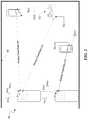
- FIG. 1is a diagram illustrating an example wireless power delivery environment 100 depicting wireless power delivery from one or more wireless chargers 101 to various wireless devices 102 within the wireless power delivery environment 100 . More specifically, FIG. 1 illustrates an example wireless power delivery environment 100 in which wireless power and/or data can be delivered to available wireless devices 102 . 1 - 102 . n having one or more power receiver clients 103 . 1 - 103 . n (also referred to herein as “wireless power receivers” or “wireless power clients”). The wireless power receivers are configured to receive isolated wireless power from one or more wireless chargers 101 .
- the wireless devices 102 . 1 - 102 . nare mobile phone devices 102 . 2 and 102 . n , respectively, and a wireless game controller 102 . 1 , although the wireless devices 102 . 1 - 102 . n can be any (smart or dumb) wireless device or system that needs power and is capable of receiving wireless power via one or more integrated power receiver clients 103 . 1 - 103 . n .
- the one or more integrated power receiver clients or “wireless power receivers”receive and process power from one or more transmitters/chargers 101 . a - 101 . n and provide the power to the wireless devices 102 . 1 - 102 . n for operation thereof.
- Each charger 101can include multiple antennas 104 , e.g., an antenna array including hundreds or thousands of antennas, which are capable of delivering wireless power to wireless devices 102 .
- the antennasare adaptively-phased radio frequency antennas.
- the charger 101is capable of determining the appropriate phases to deliver a coherent power transmission signal to the power receiver clients 103 .
- the arrayis configured to emit a signal (e.g., continuous wave or pulsed power transmission signal) from multiple antennas at a specific phase relative to each other. It is appreciated that use of the term “array” does not necessarily limit the antenna array to any specific array structure.
- the antenna arraydoes not need to be structured in a specific “array” form or geometry.
- arrayor “array system” may be used include related and peripheral circuitry for signal generation, reception and transmission, such as radios, digital logic and modems.
- the charger 101can have an embedded Wi-Fi hub.
- the wireless devices 102can include one or more receive power clients 103 . As illustrated in the example of FIG. 1 , power delivery antennas 104 a and data communication antennas 104 b are shown.
- the power delivery antennas 104 aare configured to provide delivery of wireless radio frequency power in the wireless power delivery environment.
- the data communication antennasare configured to send data communications to and receive data communications from the power receiver clients 103 . 1 - 103 and/or the wireless devices 102 . 1 - 102 . n .
- the data communication antennascan communicate via Bluetooth, Wi-Fi, ZigBee, etc.
- Each power receiver client 103 . 1 - 103 . nincludes one or more antennas (not shown) for receiving signals from the chargers 101 .
- each charger 101 . a - 101 . nincludes an antenna array having one or more antennas and/or sets of antennas capable of emitting continuous wave signals at specific phases relative to each other.
- each arrayis capable of determining the appropriate phases for delivering coherent signals to the power receiver clients 102 . 1 - 102 . n .
- coherent signalscan be determined by computing the complex conjugate of a received beacon signal at each antenna of the array such that the coherent signal is properly phased for the particular power receiver client that transmitted the beacon signal.
- each component of the environmentcan include control and synchronization mechanisms, e.g., a data communication synchronization module.
- the chargers 101 . a - 101 . ncan be connected to a power source such as, for example, a power outlet or source connecting the chargers to a standard or primary alternating current (AC) power supply in a building.
- a power sourcesuch as, for example, a power outlet or source connecting the chargers to a standard or primary alternating current (AC) power supply in a building.
- ACalternating current
- one or more of the chargers 101 . a - 101 . ncan be powered by a battery or via other mechanisms.
- the power receiver clients 102 . 1 - 102 . n and/or the chargers 101 . a - 101 . nutilize reflective objects 106 such as, for example, walls or other RF reflective obstructions within range to transmit beacon signals and/or receive wireless power and/or data within the wireless power delivery environment.
- the reflective objects 106can be utilized for multi-directional signal communication regardless of whether a blocking object is in the line of sight between the charger and the power receiver client.
- each wireless device 102 . 1 - 102 . ncan be any system and/or device, and/or any combination of devices/systems that can establish a connection with another device, a server and/or other systems within the example environment 100 .
- the wireless devices 102 . 1 - 102 . ninclude displays or other output functionalities to present data to a user and/or input functionalities to receive data from the user.
- a wireless device 102can be, but is not limited to, a video game controller, a server desktop, a desktop computer, a computer cluster, a mobile computing device such as a notebook, a laptop computer, a handheld computer, a mobile phone, a smart phone, a PDA, a Blackberry device, a Treo, and/or an iPhone, etc.
- the wireless device 102can also be any wearable device such as watches, necklaces, rings or even devices embedded on or within the customer.
- Other examples of a wireless device 102include, but are not limited to, safety sensors (e.g., fire or carbon monoxide), electric toothbrushes, electronic door lock/handles, electric light switch controller, electric shavers, etc.
- the charger 101 and the power receiver clients 103 . 1 - 103 . ncan each include a data communication module for communication via a data channel.
- the power receiver clients 103 . 1 - 103 . ncan direct the wireless devices 102 . 1 - 102 . n to communicate with the charger via existing data communications modules.
- the beacon signalwhich is primarily referred to herein as a continuous waveform, can alternatively or additionally take the form of a modulated signal.
- FIG. 2is a sequence diagram 200 illustrating example operations between a wireless charger 101 and a power receiver client 103 for commencing isolated wireless power delivery, according to an embodiment.
- the charger 101subsequently sends beacon schedule information and a transmission code to the power receiver client 103 to facilitate encoding of the beacon signal by the power receiver client 103 for subsequent isolated wireless power delivery by the charger.
- the charger 101can also send power transmission scheduling information so that the power receiver client 103 knows when to expect wireless power from the charger.
- the power receiver client 103generates an encoded beacon signal using the transmission code and broadcasts the encoded beacon during a beacon transmission assignment indicated by the beacon schedule information, e.g., BBS cycle.
- the charger 101receives the beacon from the power receiver client 103 and decodes the encoded beacon signal using the transmission code provided to the client 103 to ensure that the client 103 is an authorized or selected client.
- the charger 101also detects the phase (or direction) at which the beacon signal is received and, once the charger determines that the client is authorized, delivers wireless power and/or data to the power receiver client 103 based the phase (or direction) of the received beacon.
- the charger 101can determine the complex conjugate of the phase and use the complex conjugate to deliver and/or otherwise direct wireless power to the power receiver client 103 in the same direction (or phase) in which the beacon signal was received from the power receiver client 103 .
- the charger 101includes many antennas; one or more of which are used to deliver power to the power receiver client 103 .
- the charger 101can detect phases at which the beacon signals are received at each antenna. The large number of antennas may result in different coded beacon signals being received at each antenna of the charger 101 .
- the chargermay then determine the complex conjugate of the beacon signals received at each antenna. Using the complex conjugates, one or more antenna may emit a signal that takes into account the effects of the large number of antennas in the charger 101 . In other words, the charger 101 emits a signal from one or more antennas in such a way as to create an aggregate signal from the one or more of the antennas that approximately recreates the waveform of the beacon in the opposite direction.
- wireless powercan be delivered in power cycles defined by power schedule information.
- a more detailed example of the signaling required to commence wireless power deliveryis described now with reference to FIG. 3 .
- FIG. 3is a block diagram illustrating example components of a wireless charger 300 , in accordance with an embodiment.
- the wireless charger 300includes a master bus controller (MBC) board and multiple mezzanine boards that collectively comprise the antenna array.
- the MBCincludes control logic 310 , an external data interface (I/F) 315 , an external power interface (I/F) 320 , a communication block 330 , and proxy 340 .
- the mezzanine (or antenna array boards 350 )each include multiple antennas 360 a - 360 n . Some or all of the components can be omitted in some embodiments. Additional components are also possible.
- the control logic 310is configured to provide control and intelligence to the array components.
- the control logic 310may comprise one or more processors, FPGAs, memory units, etc., and direct and control the various data and power communications.
- the communication block 330can direct data communications on a data carrier frequency, such as the base signal clock for clock synchronization.
- the data communicationscan be Bluetooth, Wi-Fi, ZigBee, etc.
- the proxy 340can communicate with clients via data communications as discussed herein.
- the data communicationscan be Bluetooth, Wi-Fi, ZigBee, etc.
- control logic 310can also facilitate and/or otherwise enable data aggregation for Internet of Things (IoT) devices.
- IoTInternet of Things
- wireless power clientscan access, track and/or otherwise obtain IoT information about the device in which the wireless power receiver is embedded and provide that IoT information to the wireless charger 300 over a data connection.
- This IoT informationcan be provided to via an external data interface 315 to a central or cloud-based system (not shown) where the data can be aggregated, processed, etc.
- the central systemcan process the data to identify various trends across geographies, chargers, environments, devices, etc.
- the aggregated data and or the trend datacan be used to improve operation of the devices via remote updates, etc.
- the aggregated datacan be provided to third party data consumers.
- the wireless chargeracts as a Gateway or Enabler for the IoTs.
- the IoT informationcan include capabilities of the device in which the wireless power receiver is embedded, usage information of the device, power levels of the device, information obtained by the device or the wireless power receiver itself, e.g., via sensors, etc.
- the external power interface 320is configured to receive external power and provide the power to various components.
- the external power interface 320may be configured to receive a standard external 24 Volt power supply. Alternative configurations are also possible.
- the master bus controllerwhich controls the charger array, first receives power from a power source and is activated.
- the MBCthen activates the proxy antenna elements on the charger array and the proxy antenna elements enter a default “discovery” mode to identify available wireless receiver clients within range of the charger array.
- the antenna elements on the charger arraypower on, enumerate, and (optionally) calibrate.
- the MBCgenerates beacon transmission scheduling information and power transmission scheduling information during a scheduling process.
- the scheduling processincludes selection of power receiver clients.
- the MBCcan select power receiver clients for power transmission and generate a Beacon Beat Schedule (BBS) cycle and a Power Schedule (PS) for the selected wireless power receiver clients.
- BBSBeacon Beat Schedule
- PSPower Schedule
- a graphical signaling representation of an example BBS and PSis shown and discussed in greater detail with reference to FIGS. 6 and 7 .
- the power receiver clientscan be selected based on their corresponding properties and/or requirements.
- the MBCcan also identify and/or otherwise select available clients that will have their status queried in the Client Query Table (CQT). Clients that are placed in the CQT are those on “standby”, e.g., not receiving a charge.
- the BBS and PSare calculated based on vital information about the clients such as, for example, battery status, current activity/usage, how much longer the client has until it runs out of power, priority in terms of usage, etc.
- the Proxy AEbroadcasts the BBS to all clients.
- the BBSindicates when each client should send a beacon.
- the PSindicates when and to which clients the array should send power to.
- Each clientstarts broadcasting its beacon and receiving power from the array per the BBS and PS.
- the Proxycan concurrently query the Client Query Table to check the status of other available clients.
- a clientcan only exist in the BBS or the CQT (e.g., waitlist), but not in both.
- a limited number of clientscan be served on the BBS and PS (e.g., 32).
- the CQTmay also be limited to a number of clients (e.g., 32).
- the information collected in the previous stepcontinuously and/or periodically updates the BBS cycle and/or the PS.
- FIG. 4is a block diagram illustrating example components of a wireless power receiver (client), in accordance with some embodiments.
- the receiver 400includes control logic 410 , battery 420 , an IoT control module 425 , communication block 430 and associated antenna 470 , power meter 440 , rectifier 450 , a combiner 455 , beacon signal generator 460 , beacon coding unit 462 and an associated antenna 480 , and switch 465 connecting the rectifier 450 or the beacon signal generator 460 to one or more associated antennas 490 a - n .
- Some or all of the componentscan be omitted in some embodiments.
- the wireless power receiver clientdoes not include its own antennas but instead utilizes and/or otherwise shares one or more antennas (e.g., Wi-Fi antenna) of the wireless device in which the wireless power receiver is embedded. Additional components are also possible.
- a combiner 455receives and combines the received power transmission signals from the power transmitter in the event that the receiver 400 has more than one antenna.
- the combinercan be any combiner or divider circuit that is configured to achieve isolation between the output ports while maintaining a matched condition.
- the combiner 455can be a Wilkinson Power Divider circuit.
- the rectifier 450receives the combined power transmission signal from the combiner 455 , if present, which is fed through the power meter 440 to the battery 420 for charging.
- the power meter 440measures the received power signal strength and provides the control logic 410 with this measurement.
- the control logic 410also may receive the battery power level from the battery 420 itself.
- the control logic 410may also transmit/receive via the communication block 430 a data signal on a data carrier frequency, such as the base signal clock for clock synchronization.
- the beacon signal generator 460generates the beacon signal, or calibration signal, transmits the beacon signal using either the antenna 480 or 490 after the beacon signal is encoded.
- the receiver 400may also receive its power directly from the rectifier 450 . This may be in addition to the rectifier 450 providing charging current to the battery 420 , or in lieu of providing charging. Also, it may be noted that the use of multiple antennas is one example of implementation and the structure may be reduced to one shared antenna.
- control logic 410 and/or the IoT control module 425can communicate with and/or otherwise derive IoT information from the device in which the wireless power receiver client 400 is embedded.
- the wireless power receiver client 400can have one or more data connections (wired or wireless) with the device in which the wireless power receiver client 400 is embedded over which IoT information can be obtained.
- IoT informationcan be determined and/or inferred by the wireless power receiver client 400 , e.g., via one or more sensors.
- the IoT informationcan include, but is not limited to, information about the capabilities of the device in which the wireless power receiver is embedded, usage information of the device in which the wireless power receiver is embedded, power levels of the battery or batteries of the device in which the wireless power receiver is embedded, and/or information obtained or inferred by the device in which the wireless power receiver is embedded or the wireless power receiver itself, e.g., via sensors, etc.
- a client identifier (ID) module 415stores a client ID that can uniquely identify the power receiver client in a wireless power delivery environment. For example, the ID can be transmitted to one or more chargers when communication are established.
- power receiver clientsmay also be able to receive and identify other power receiver clients in a wireless power delivery environment based on the client ID.
- An optional motion sensor 495can detect motion and signal the control logic 410 to act accordingly. For example, when a device is receiving power at high frequencies, e.g., above 500 MHz, its location may become a hotspot of (incoming) radiation. Thus, when the device is on a person, e.g., embedded in a mobile device, the level of radiation may exceed acceptable radiation levels set by the Federal Communications Commission (FCC) or other medical/industrial authorities. To avoid any potential radiation issue, the device may integrate motion detection mechanisms such as accelerometers or equivalent mechanisms. Once the device detects that it is in motion, it may be assumed that it is being handled by a user, and would trigger a signal to the array either to stop transmitting power to it, or to lower the received power to an acceptable fraction of the power. In cases where the device is used in a moving environment like a car, train or plane, the power might only be transmitted intermittently or at a reduced level unless the device is close to losing all available power.
- FCCFederal Communications Commission
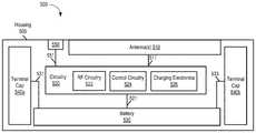
- FIG. 5depicts a block diagram illustrating example components of a wirelessly chargeable battery apparatus 500 , according to some embodiments.
- the wireless power reception apparatus 500includes a housing 505 , one or more antennas 510 , circuitry 520 , one or more batteries (or battery modules) 530 , a user interface 550 , and terminals caps 540 a and 540 b .
- the circuitry 520includes radio frequency (RF) circuitry 522 , control circuitry 524 , and charging electronics 526 .
- RFradio frequency
- the one or more antennas 510are connected to the circuitry 520 via a connection 511 and the circuitry is connected to the one or more batteries 530 via a connection 521 .
- the circuitryis also connected to the power interface 540 via a connection 541 and to a user interface via a connection 551 .
- the connections 511 , 521 , 531 , 533 , and 551may be traces on a printed circuit board, physical wires, or any other mechanism.
- the housing 505is configured in dimensions that conform to standardized battery dimensions. Accordingly, the wirelessly chargeable battery apparatus is retrofittable into existing portable electronic devices without redesign of those electronic devices.
- the portable electronic devicecan be any portable or mobile electronic device that is powered by rechargeable or non-rechargeable batteries, e.g., game controllers, remote controls, alarm systems, etc.
- the portable electronic devicescan also be devices with less standardized rechargeable batteries such as, for example, mobile phones, tablet computers, etc.
- the wirelessly chargeable battery apparatuscan include some or all of the components of a wireless power receiver client, the components of which are discussed in greater detail above.
- the housing 505is configured in dimensions that conform to standardized battery dimensions.
- the example of FIG. 5 with terminal caps 540 a and 540 bis not shown to scale.
- the housing 505can be configured in cylindrical or non-cylindrical cell battery form factors, camera battery form factors, button cell battery form factors, etc.
- the standard form factorcan be, among other form factors, AA, AAA, C, D, 4.5-vot, 9-volt, Lantern (spring) battery form factors.
- the standard form factorcan be a form factor that is configured to power mobile devices, including, but not limited to, mobile phone batteries, tablet computer batteries, etc.
- Example wirelessly chargeable battery apparatusesare shown and discussed in cylindrical form factor. However, as discussed herein, the wirelessly chargeable battery apparatuses are not limited to cylindrical form factors.
- the one or more antennas 510are configured to receive a wireless power signal from a wireless charging system, e.g., a wireless charger.
- the wireless power signalscan include alternating current (AC) power.
- the circuitry 520includes RF circuitry 522 , control circuitry 524 and charging electronics 526 .
- the one or more antennascan be located within the housing on one or more printed circuit boards (PCBs), flexible PCBs, embedded on or within the interior surface of the housing 505 , and/or embedded on or within the exterior surface of the housing 505 including combinations and/or variations thereof.
- PCBsprinted circuit boards
- flexible PCBsembedded on or within the interior surface of the housing 505
- the exterior surface of the housing 505including combinations and/or variations thereof.
- the RF circuitry 522 and the control circuitry 524can perform the various control functions of a wireless power receiver as discussed in greater detail above with reference to FIG. 4 .
- the RF circuitry 522 and/or other components of the circuitry 520can process the wireless power received via the one or more antennas 510 and convert received wireless RF Power to direct current (DC) power.
- the RF Poweris alternating current (AC) power.
- the charging electronics 526can, among other functions, detect status information of the one or more batteries 530 and/or one or more internal battery of the portable electronic device to which the housing is attached and control the charging of the one or more batteries 530 based on this information.
- the one or more batteries 530can store the DC power.
- the wirelessly chargeable battery apparatusmay not include a battery but instead directly charge one or more batteries of a portable electronic device to which it is removably attached.
- the wirelessly chargeable battery apparatus 500includes terminal caps 540 a and 540 b over which power can be exchanged between the battery 530 and/or circuitry 520 and the portable electronic device when wirelessly the wirelessly chargeable battery apparatus 500 is inserted into a battery recess of the portable electronic device.
- the user interface 550can include an interface configured to provide information to a user of a portable electronic device and/or an interface configured to allow the user of the portable electronic device to provide information to the wirelessly chargeable battery apparatus 500 .
- light emitting diodesLEDs
- an LEDcan display a particular color to indicate each battery charging state (e.g., low, med, or high) for battery 530 .
- the user interface 550can also include one or more user buttons or switches.
- an ON/OFF switchcan be provided on the wirelessly chargeable battery apparatus 500 to control whether or not the apparatus should process wireless power.
- a buttoncan be provided that, once pressed, activates charging of the one or more batteries of a portable electronic device using the energy stored in the one or more batteries 530 of the wirelessly chargeable battery apparatus 500 .
- Other user interface embodimentsare also possible.
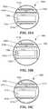
- FIGS. 6A-6Cdepict a wirelessly chargeable battery apparatus 600 packaged in a cylindrical form factor, according to some embodiments. More specifically, the example of FIGS. 6A-6C illustrate a front perspective, and cross-sectional side and top views of an example wirelessly chargeable battery apparatus 600 packaged in a housing 605 configured in dimensions that conform to a standard AA type battery.
- the wirelessly chargeable battery apparatus 600may be wirelessly chargeable battery apparatus 500 of FIG. 5 , although alternative configurations are possible.
- the wirelessly chargeable battery apparatus 600includes an antenna 610 , circuit boards 622 and 624 , a battery 630 , and terminal caps 640 a and 640 b .
- a board-to-board connector 611connects the circuit boards 622 and 624 .
- the circuit boards 622 and 624can include one or more dielectrics 615 configured to provide isolation.
- the circuit boards 622 and 624comprise printed circuit boards (PCBs) that comprise the dielectric material.
- the terminal caps 640 a and 640 bare shown connected to battery 630 via wires 631 and 633 , respectively.
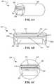
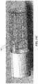
- FIGS. 7A and 7Bdepict an example wirelessly chargeable battery apparatus packaged in cylindrical form factor, according to some embodiments. More specifically, the examples of FIGS. 7A and 7B illustrate the example wirelessly chargeable battery apparatuses 700 a and 700 b having a director or reflector plane 725 on the exterior of the housing 705 and the interior of the housing 705 , respectively. As shown in the examples of FIGS. 7A-7B , the wirelessly chargeable battery apparatuses 700 a and 700 b include the housing 705 , at least one antenna 710 , control circuitry and antenna/RF circuitry 720 , a battery 730 and the director or reflector plane 725 .
- Director or reflector planes 725can direct and/or otherwise reflect or modify the antenna transmission and/or reception radiation pattern to increase antenna efficiency. As discussed herein, the antenna efficiency includes both the ability to transmit a stronger beacon signal to a wireless power transmission system as well as the ability to receive more power, e.g., stronger signals, from a wireless transmission system. Furthermore, although the director or reflector plane 725 is shown positioned at the top of the housing 705 , the director or reflector plane 725 can be located anywhere on or within the housing 705 .
- FIGS. 8A and 8Bdepict another example wirelessly chargeable battery apparatus packaged in cylindrical form factor, according to some embodiments. More specifically, the examples of FIGS. 8A and 8B illustrate the example wirelessly chargeable battery apparatuses 800 a and 800 b having multiple director or reflector planes 825 on the exterior of the housing 805 and the interior of the housing 805 , respectively. As shown in the examples of FIGS. 8A and 8B , the wirelessly chargeable battery apparatuses 800 a and 800 b include the housing 705 , at least one antenna 810 , control circuitry and antenna/RF circuitry 820 , a battery 830 and the multiple director or reflector planes 825 .
- the director or reflector planes 825can direct and/or otherwise reflect or modify the antenna transmission and/or reception radiation pattern to increase antenna efficiency.
- the multiple director or reflector planes 825are shown either on the exterior or the interior of the housing 805 in the examples of FIGS. 8A and 8B , it is appreciated that other embodiments could include director or reflector planes 825 located and/or otherwise situated both inside and outside of the housing 805 .
- one or more director or reflector planes 825can be included with a sleeve or casing that fits over a wirelessly chargeable battery apparatus.
- the sleeve or casingcan include the one or more director or reflector planes 825 on the interior or the exterior of the sleeve or casing including combinations and/or variations thereof.
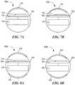
- FIGS. 9A-9Cdepict front perspective views of various example wirelessly chargeable battery apparatuses, according to some embodiments. More specifically, the examples of FIGS. 9A-9C illustrate various example antenna configurations or types that can be used on or within a wirelessly chargeable battery apparatus, according to some embodiments. More specifically, the examples of FIGS. 9A-9C illustrate a bowtie antenna configuration 910 a , a slot antenna configuration 910 b and a dipole antenna configuration 910 c , according to some embodiments. The example of FIGS. 9A-9C are shown packaged in a cylindrical form factor, however, it is appreciated that other form factors are also possible.
- FIGS. 9A-9Cinclude housing 905 a - 905 C, antennas 910 a - 910 c , control circuitry and antenna/RF circuitry 920 a - 920 c , and batteries 930 a - 930 c .
- the example antenna configuration or typescan be configured and/or otherwise embedded onto the exterior of housing 905 or situated and/or otherwise embedded into the interior of the housing 905 .
- the configurations shown with respect to FIGS. 9A-9Care example configurations. Embodiments can include combinations and/or variations of thereof.
- the slot antenna configuration of FIG. 9Bcould be situated along the length of the housing 905 b as opposed to the width.
- FIGS. 10A-10Cdepict various additional example topologies of wirelessly chargeable battery apparatuses, according to some embodiments. More specifically, the examples of FIGS. 10A-10C depict cross-sectional top views of example wirelessly chargeable battery apparatuses 1000 a - 1000 c packaged in a housing 1005 . In the examples of FIGS. 10A-10C , housing 1005 configured in dimensions that conform to a standard AA type battery.
- FIGS. 10A-10Cillustrate embodiments of wirelessly chargeable battery apparatuses having multiple radiators, e.g., antennas 1010 a - 1010 c and 1012 a - 1012 c , one on the battery 1030 a - 1030 c side and one on the RF side in communication with antenna/RF board 1022 a - 1022 c . Additionally, the examples of FIGS. 10A-10C illustrate a flexible dielectric 1015 a - 1015 c that is configured to isolate the antenna 1012 a - 1012 c from the battery 1030 a - 1030 c , respectively.
- the dielectric 1015 a - 1015 c and/or other dielectricscan be designed and/or otherwise configured to isolate and direct the antenna transmission and/or reception patterns.
- PCB boardsinclude a ground plane on one side, e.g., copper plane that acts as ground plane.
- the board antenna/RF circuit boards 1022 a - 1022 cinclude copper ground planes 1023 a - 1023 c that act as another dielectric to isolate and direct the antenna transmission and/or reception patterns of antenna 1010 a - 1010 c.
- the batteries 1030 a - 1030 ccan be used as ground planes with the use of the flexible dielectric 1015 a - 1015 c . More specifically, the example of FIG. 10B shows the flexible dielectric 1015 b wrapped around the battery 1030 b . Additionally, as discussed in greater detail with reference to FIGS. 7A-8B , the example of FIG. 10C also includes one or more director or reflector planes 1025 .
- FIGS. 11A and 11Bdepict a cross sectional top view and a front perspective view, respectively, of an example wirelessly chargeable battery apparatus 1100 having a flexible printed circuit board 1120 , according to some embodiments. More specifically, the examples of FIGS. 11A and 11B illustrate an example wirelessly chargeable battery apparatus 1100 that includes a spatial controller 1121 which is configured to automatically rotate movable components of the wirelessly chargeable battery apparatus 1100 for optimal antenna configuration.
- the flexible printed circuit board 1120comprises both control circuitry and antenna/RF circuitry. Additionally, although not shown, the flexible printed circuit board 1120 can include or be in contact with one or more antennas that rotate along with the flexible printed circuit board 1120 . In some embodiments, the battery 1130 optionally rotates along with the flexible printed circuit board 1120 . Alternatively, the battery 1130 can remain in a fixed position.
- the spatial controller 1121comprises a coil or spring that automatically adjusts the movable components of the wirelessly chargeable battery apparatus 1100 such that the one or more antennas are optimally positioned for receiving power.
- the optimal position for receiving poweris the position in which the most power is received from the power transmission system.
- the received powercan be processed and used to power the coil or spring.
- the coil or springcan be controlled by small voltages and/or sensors.
- small motors, liquid metals, etc.can be used in place of or in addition to the coil or spring in order to control the orientation of the movable components of the wirelessly chargeable battery apparatus 1100 .
- FIGS. 12A-12Cdepict a front perspective view and two cross sectional top views, respectively, of example multi-wirelessly chargeable battery apparatus 1200 a - 1200 c , according to some embodiments. More specifically, as shown in the examples of FIGS. 12A-12C , the multi-wirelessly chargeable battery apparatuses 1200 a - 1200 c each include two wirelessly chargeable battery apparatuses.
- the wirelessly chargeable battery apparatusescould be any the apparatuses discussed herein, although alternative configurations are possible.
- the multi-wirelessly chargeable battery apparatuses 1200 a - 1200 cinclude package covers 1206 a - 1206 c , antennas, antenna/RF circuit boards, control circuit boards, and batteries.
- the multi-wirelessly chargeable battery apparatuses 1200 a - 1200 cinclude package covers that are configured in dimensions that conform to a two standard AA type batteries. More specifically, package covers 1206 b and 1206 c are shown as rectangular packages while package 1206 is configured to closely mimic the dimensions of the multiple standardized batteries.
- the antennascan be configured internally or externally.
- the antennasare embedded and/or otherwise places on or within the package covers 1206 a - 1206 c for increased surface area.
- FIG. 12Billustrates antennas 1210 b and 1212 c embedded and/or otherwise placed on the exterior of the package cover 1206 b
- FIG. 12Cillustrates antennas 1210 b and 1212 b embedded and/or otherwise placed on the exterior of the package cover 1206 b
- the example of FIG. 12Cillustrates antennas 1210 c and 1212 c embedded and/or otherwise placed on the interior of the package cover 1206 c .
- Alternative configurationsare also possible.
- antennascould be placed and/or otherwise embedded within the package cover. Combinations and/or variations of the discussed embodiments are also possible.
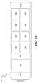
- FIGS. 13A-13Ddepict various front perspective views and a cross sectional top view, respectively, of example multi-wirelessly chargeable battery apparatus packages 1300 a - 1300 d , according to some embodiments. More specifically, the examples of FIGS. 13A-13D illustrate various example antenna configurations that are embedded and/or otherwise situated on or within a multi-wirelessly chargeable battery apparatus package cover.
- the antenna configurationsinclude a multi-bowtie configuration ( FIG. 13A ), a slot configuration ( FIG. 13B ), a dipole configuration ( FIG. 13C ), and a cube antenna structure configuration ( FIG. 13D ).
- Other configurationsare also possible.
- the cube antenna structure configuration of FIG. 13Dincludes one or more antennas that are wrapped around the multi-wireless power reception apparatus package. This type of configuration generally radiates in every direction and thus does not require that the package be inserted or otherwise placed in a device in a particular orientation.
- each face of the cube antenna structure configurationcan be a dynamically configurable antenna.
- the multi-wirelessly chargeable battery apparatusmay include one or more controllers that monitor the antennas and dynamically configure which antennas provide optimal power reception.
- FIGS. 14A-14Cdepict an example wirelessly chargeable battery apparatus 1400 configured in dimensions that conform to a standard AA type battery, according to some embodiments. More specifically, FIGS. 14A-14C illustrate the wirelessly chargeable battery apparatus 1400 with a two-piece detachable housing.
- FIG. 14Aillustrates the wirelessly chargeable battery apparatus 1400 with each of the two-piece detachable housing 1440 a and 1440 b attached.
- the housing 1440 a and 1440 bwhen attached, are circular on one end and hexagonal on the opposite end.
- the housing 1440 a and 1440 bis circular near a first terminal cap 1440 a and hexagonal near a second terminal cap 1140 b .
- terminal cap 1440 ais circular and terminal cap 1440 b is hexagonal.
- the housing piece 1440 bincludes interfaces 1407 and 1408 .
- Interface 1407is an external switch which can, for example, enable or disable the wirelessly chargeable battery apparatus 1400 , e.g., sleep or awake mode, etc.
- the interface 1408can be an indicator interface such as, for example, indicator lights or light emitting diodes (LEDs).
- LEDslight emitting diodes
- LEDscan be used to indicate various statuses of the wirelessly chargeable battery apparatus 500 .
- an LEDcan display a particular color to indicate a battery charging state (e.g., low, med, or high).
- Other user interface embodimentsare also possible.
- FIG. 14Billustrates components of the wirelessly chargeable battery apparatus 1400 with the two-piece detachable housing 1440 a and 1440 b detached.
- the wirelessly chargeable battery apparatus 1400includes the housing 1405 a and 1405 b , antenna 1410 , RF/Antenna board 1422 , control board 1424 , a board-to-board connector 1423 , a charging/electronics components 1425 (e.g., on RF/Antenna board 1422 and/or control board 1424 ), terminal caps 1440 a and 1440 b , battery connections 1421 , and a battery 1430 .
- FIG. 14Cillustrates the wirelessly chargeable battery apparatus 1400 and, more particular, housing 1440 a including snap on extrudes 1407 that snap into corresponding latches on housing 1440 b to attach and/or otherwise fasten.
- Other physical connection mechanismsare also possible.
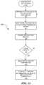
- FIG. 15depicts flow diagrams illustrating an example process 1500 for dynamically selecting an optimal antenna polarity, according to some embodiments. More specifically, the example of FIG. 15 illustrates an example polarity configuration cycle whereby the optimal antenna polarity can be determined and configured.
- a wirelessly chargeable battery apparatuscan, among other functions, perform the corresponding steps of example process 1500 .
- the wirelessly chargeable battery apparatuscan be wirelessly chargeable battery apparatus 500 of FIG. 5 , although alternative configurations are possible.
- the wirelessly chargeable battery apparatusconfigures the antenna(s) based on a first of multiple antenna polarity configurations or modes. Initially, the wirelessly chargeable battery apparatus configures the antenna polarity to a “default” or base mode. As discussed herein, the wirelessly chargeable battery apparatus includes one or more antennas having configurable polarity. In some embodiments, the polarity is configured by adjusting, e.g., activating or deactivating, antenna feeds or different antennas.
- the wirelessly chargeable battery apparatusreceives power from a wireless power transmission system, e.g., wireless charger.
- the wirelessly chargeable battery apparatusprocesses the received wireless power and measures a quantity or amount of wireless power received. Alternatively, or additionally, the wirelessly chargeable battery apparatus may measure the signal strength of the received wireless power signals. In some embodiments, the wirelessly chargeable battery apparatus saves and/or otherwise stores the measured power or signal strength measurement in conjunction with the antenna polarity mode.
- the wirelessly chargeable battery apparatusdetermines if the wirelessly chargeable battery apparatus has cycled through each of the antenna polarity modes. If not, the process continues at step 1510 with the wirelessly chargeable battery apparatus configuring the next antenna polarity configuration. However, if the wirelessly chargeable battery apparatus has cycled through each of the antenna polarity modes, at step 1518 , the wirelessly chargeable battery apparatus selects an optimal polarity configuration or antenna polarity mode. As discussed herein, the optimal antenna polarity is the polarity at which the wirelessly chargeable battery apparatus receives the most wireless power or the strongest signal from one or more chargers within a wireless power delivery environment. Lastly, at step 1520 , the antennas are configured based on the selected antenna polarity configuration if they are not already configured in the selected mode.
- FIGS. 16A-16Dillustrate various views of an example client (wireless power receiver) packaged in a standard battery form factor, according to some embodiment. More specifically, the examples of FIG. 16A-16D illustrate front perspective, top, bottom and side views, respectively, of an example client (wireless power receiver) packaged in a standard AA type battery form factor.
- the client (wireless power receiver)can be packaged in any standard battery form factor including, cylindrical and non-cylindrical cells or batteries, camera batteries, button cells, etc.
- the example client (wireless power receiver)can be packaged in AA, AAA, C, D, 4.5-vot, 9-volt, Lantern (spring), etc.
- each wireless devicecan have a different multi-battery configuration.
- a single battery with integrated wireless charging functionalitycan be utilized with a dummy cell for a device requiring two batteries (e.g. two AA batteries).
- the multi-battery configurationscan require different voltages depending on the type of battery, the number of batteries, and the configuration (e.g., number of batteries in parallel and number of batteries in series).
- FIGS. 17A-Dillustrate various examples of multi-battery configurations, according to some embodiments.
- each wireless devicecan have different multi-battery configurations requiring different voltage to power the wireless device.
- FIG. 17Aillustrates a standard AA cell 1.5V battery.
- FIGS. 17B and 17Cillustrate two configurations of two side-by-side standard AA cell 1.5V batteries where the positive and negative contacts do not align and where they do, respectively.
- FIG. 17Dillustrates an example of two standard AA cell 1.5V batteries in series where the configuration provides 3 Volts when measured end-to-end.
- FIG. 18is a diagram illustrating an example battery 1800 with integrated wireless charging functionality and variable output voltage, according to an embodiment.
- the example battery 1800includes antennas 1804 a and 1804 b , wireless power receiver circuitry (e.g., a client) 1810 , and voltage configuration module 1820 , and multiple storage cells 1825 .
- the output voltage of the example battery 1800can vary based on the configuration of the storage cells 1825 .
- the storage cells 1825can be configurable and/or reconfigurable by a voltage configuration module 1820 .
- the wireless power receiver circuitry (e.g., a client) 1810can include one or more of the components of a client (wireless power receiver), as described herein.
- the voltage configuration module 1820can automatically configure the voltage based on information received from dummy cells.
- the voltage configuration module 1820can be configurable/reconfigurable by a user. Other methods of configuration are also possible.
- FIGS. 19A and 19Billustrate an example battery 1910 having an integrated wireless charging module 1915 and one or more storage cells in a storage module 1925 .
- the wireless charging module 1915 and the storage module 1925can be packaged in a 9-Volt battery.
- a front cover 1930snaps into the base to keep the components in the 9-Volt battery package. In some embodiments, these components can be removable and/or replaceable.
- multi-battery configurationscan include multiple batteries integrated with wireless charging functionality.
- the multi-battery configurationscan include multiple batteries with one or more integrated with wireless charging functionality and one or more comprising batteries that are chargeable/rechargeable via the one or more integrated with the wireless charging functionality.
- FIG. 20depicts a block diagram illustrating example components of a representative mobile device or tablet computer 2000 with a wireless power receiver or client in the form of a mobile (or smart) phone or tablet computer device, according to an embodiment.
- Various interfaces and modulesare shown with reference to FIG. 20 , however, the mobile device or tablet computer does not require all of modules or functions for performing the functionality described herein.
- various componentsare not included and/or necessary for operation of the category controller.
- componentssuch as GPS radios, cellular radios, and accelerometers may not be included in the controllers to reduce costs and/or complexity.
- componentssuch as ZigBee radios and RFID transceivers, along with antennas, can populate the Printed Circuit Board.
- the wireless power receiver clientcan be a power receiver clients 103 of FIG. 1 , although alternative configurations are possible. Additionally, the wireless power receiver client can include one or more RF antennas for reception of power and/or data signals from a charger, e.g., charger 101 of FIG. 1 .
- FIG. 21depicts a diagrammatic representation of a machine, in the example form, of a computer system within which a set of instructions, for causing the machine to perform any one or more of the methodologies discussed herein, may be executed.
- the computer systemincludes a processor, memory, non-volatile memory, and an interface device.
- Various common componentse.g., cache memory
- the computer system 2100is intended to illustrate a hardware device on which any of the components depicted in the example of FIG. 1 (and any other components described in this specification) can be implemented.
- the computer systemcan be any radiating object or antenna array system.
- the computer systemcan be of any applicable known or convenient type.
- the components of the computer systemcan be coupled together via a bus or through some other known or convenient device.
- the processormay be, for example, a conventional microprocessor such as an Intel Pentium microprocessor or Motorola power PC microprocessor.
- Intel Pentium microprocessoror Motorola power PC microprocessor.
- machine-readable (storage) mediumor “computer-readable (storage) medium” include any type of device that is accessible by the processor.
- the memoryis coupled to the processor by, for example, a bus.
- the memorycan include, by way of example but not limitation, random access memory (RAM), such as dynamic RAM (DRAM) and static RAM (SRAM).
- RAMrandom access memory
- DRAMdynamic RAM
- SRAMstatic RAM
- the memorycan be local, remote, or distributed.
- the busalso couples the processor to the non-volatile memory and drive unit.
- the non-volatile memoryis often a magnetic floppy or hard disk, a magnetic-optical disk, an optical disk, a read-only memory (ROM), such as a CD-ROM, EPROM, or EEPROM, a magnetic or optical card, or another form of storage for large amounts of data. Some of this data is often written, by a direct memory access process, into memory during execution of software in the computer 2100 .
- the non-volatile storagecan be local, remote, or distributed.
- the non-volatile memoryis optional because systems can be created with all applicable data available in memory.
- a typical computer systemwill usually include at least a processor, memory, and a device (e.g., a bus) coupling the memory to the processor.
- Softwareis typically stored in the non-volatile memory and/or the drive unit. Indeed, for large programs, it may not even be possible to store the entire program in the memory. Nevertheless, it should be understood that for software to run, if necessary, it is moved to a computer readable location appropriate for processing, and for illustrative purposes, that location is referred to as the memory in this paper. Even when software is moved to the memory for execution, the processor will typically make use of hardware registers to store values associated with the software, and local cache that, ideally, serves to speed up execution. As used herein, a software program is assumed to be stored at any known or convenient location (from non-volatile storage to hardware registers) when the software program is referred to as “implemented in a computer-readable medium”. A processor is considered to be “configured to execute a program” when at least one value associated with the program is stored in a register readable by the processor.
- the busalso couples the processor to the network interface device.
- the interfacecan include one or more of a modem or network interface. It will be appreciated that a modem or network interface can be considered to be part of the computer system.
- the interfacecan include an analog modem, isdn modem, cable modem, token ring interface, satellite transmission interface (e.g. “direct PC”), or other interfaces for coupling a computer system to other computer systems.
- the interfacecan include one or more input and/or output devices.
- the I/O devicescan include, by way of example but not limitation, a keyboard, a mouse or other pointing device, disk drives, printers, a scanner, and other input and/or output devices, including a display device.
- the display devicecan include, by way of example but not limitation, a cathode ray tube (CRT), liquid crystal display (LCD), or some other applicable known or convenient display device.
- CTRcathode ray tube
- LCDliquid crystal display
- controllers of any devices not depicted in the example of FIG. 21reside in the interface.
- the computer system 2100can be controlled by operating system software that includes a file management system, such as a disk operating system.
- a file management systemsuch as a disk operating system.
- operating system software with associated file management system softwareis the family of operating systems known as Windows® from Microsoft Corporation of Redmond, Wash., and their associated file management systems.
- Windows®from Microsoft Corporation of Redmond, Wash.
- Windows®from Microsoft Corporation of Redmond, Wash.
- Linux operating systemis the Linux operating system and its associated file management system.
- the file management systemis typically stored in the non-volatile memory and/or drive unit and causes the processor to execute the various acts required by the operating system to input and output data and to store data in the memory, including storing files on the non-volatile memory and/or drive unit.
- the machineoperates as a standalone device or may be connected (e.g., networked) to other machines.
- the machinemay operate in the capacity of a server or a client machine in a client-server network environment or as a peer machine in a peer-to-peer (or distributed) network environment.
- the machinemay be a server computer, a client computer, a personal computer (PC), a tablet PC, a laptop computer, a set-top box (STB), a personal digital assistant (PDA), a cellular telephone, an iPhone, a Blackberry, a processor, a telephone, a web appliance, a network router, switch or bridge, or any machine capable of executing a set of instructions (sequential or otherwise) that specify actions to be taken by that machine.
- PCpersonal computer
- PDApersonal digital assistant
- machine-readable medium or machine-readable storage mediumis shown in an exemplary embodiment to be a single medium, the term “machine-readable medium” and “machine-readable storage medium” should be taken to include a single medium or multiple media (e.g., a centralized or distributed database, and/or associated caches and servers) that store the one or more sets of instructions.
- the term “machine-readable medium” and “machine-readable storage medium”shall also be taken to include any medium that is capable of storing, encoding or carrying a set of instructions for execution by the machine and that cause the machine to perform any one or more of the methodologies of the presently disclosed technique and innovation.
- routines executed to implement the embodiments of the disclosuremay be implemented as part of an operating system or a specific application, component, program, object, module or sequence of instructions referred to as “computer programs.”
- the computer programstypically comprise one or more instructions set at various times in various memory and storage devices in a computer, and that, when read and executed by one or more processing units or processors in a computer, cause the computer to perform operations to execute elements involving the various aspects of the disclosure.
- machine-readable storage mediamachine-readable media, or computer-readable (storage) media
- recordable type mediasuch as volatile and non-volatile memory devices, floppy and other removable disks, hard disk drives, optical disks (e.g., Compact Disk Read-Only Memory (CD ROMS), Digital Versatile Disks, (DVDs), etc.), among others, and transmission type media such as digital and analog communication links.
- CD ROMSCompact Disk Read-Only Memory
- DVDsDigital Versatile Disks
- transmission type mediasuch as digital and analog communication links.
- the words “comprise,” “comprising,” and the likeare to be construed in an inclusive sense, as opposed to an exclusive or exhaustive sense; that is to say, in the sense of “including, but not limited to.”
- the terms “connected,” “coupled,” or any variant thereofmeans any connection or coupling, either direct or indirect, between two or more elements; the coupling of connection between the elements can be physical, logical, or a combination thereof.
- the words “herein,” “above,” “below,” and words of similar importwhen used in this application, shall refer to this application as a whole and not to any particular portions of this application.
- words in the above Detailed Description using the singular or plural numbermay also include the plural or singular number respectively.
- the word “or,” in reference to a list of two or more items,covers all of the following interpretations of the word: any of the items in the list, all of the items in the list, and any combination of the items in the list.
Landscapes
- Engineering & Computer Science (AREA)
- Power Engineering (AREA)
- Computer Networks & Wireless Communication (AREA)
- Charge And Discharge Circuits For Batteries Or The Like (AREA)
- Support Of Aerials (AREA)
- Details Of Aerials (AREA)
- Variable-Direction Aerials And Aerial Arrays (AREA)
- Secondary Cells (AREA)
- Battery Mounting, Suspending (AREA)
Abstract
Description
Claims (24)
Priority Applications (15)
| Application Number | Priority Date | Filing Date | Title |
|---|---|---|---|
| US15/048,982US10559971B2 (en) | 2015-04-10 | 2016-02-19 | Wirelessly chargeable battery apparatus |
| KR1020177032541AKR102150155B1 (en) | 2015-04-10 | 2016-04-04 | Wireless rechargeable battery device |
| JP2017552036AJP6725531B2 (en) | 2015-04-10 | 2016-04-04 | Wireless rechargeable battery device |
| PCT/US2016/025940WO2016164321A1 (en) | 2015-04-10 | 2016-04-04 | Wirelessly chargeable battery apparatus |
| CN201680032910.5ACN107925253A (en) | 2015-04-10 | 2016-04-04 | Wireless rechargeable battery device |
| EP20156711.2AEP3709474A3 (en) | 2015-04-10 | 2016-04-04 | Wirelessly chargeable battery apparatus |
| EP16777118.7AEP3281272B1 (en) | 2015-04-10 | 2016-04-04 | Wirelessly chargeable battery apparatus |
| US15/094,963US9620996B2 (en) | 2015-04-10 | 2016-04-08 | Wireless charging with multiple power receiving facilities on a wireless device |
| US15/094,952US9632554B2 (en) | 2015-04-10 | 2016-04-08 | Calculating power consumption in wireless power delivery systems |
| US15/461,121US20170187249A1 (en) | 2015-04-10 | 2017-03-16 | Wireless Charging With Multiple Power Receiving Facilities On A Wireless Device |
| US15/461,080US10574081B2 (en) | 2015-04-10 | 2017-03-16 | Calculating power consumption in wireless power delivery systems |
| US16/786,180US11043833B2 (en) | 2015-04-10 | 2020-02-10 | Wirelessly chargeable battery apparatus |
| JP2020109328AJP7047019B2 (en) | 2015-04-10 | 2020-06-25 | Wireless rechargeable battery device |
| US17/244,964US12088117B2 (en) | 2015-04-10 | 2021-04-30 | Wirelessly chargeable battery apparatus |
| JP2022045362AJP7378528B2 (en) | 2015-04-10 | 2022-03-22 | wireless rechargeable battery device |
Applications Claiming Priority (3)
| Application Number | Priority Date | Filing Date | Title |
|---|---|---|---|
| US201562146233P | 2015-04-10 | 2015-04-10 | |
| US201662275383P | 2016-01-06 | 2016-01-06 | |
| US15/048,982US10559971B2 (en) | 2015-04-10 | 2016-02-19 | Wirelessly chargeable battery apparatus |
Related Child Applications (1)
| Application Number | Title | Priority Date | Filing Date |
|---|---|---|---|
| US16/786,180ContinuationUS11043833B2 (en) | 2015-04-10 | 2020-02-10 | Wirelessly chargeable battery apparatus |
Publications (2)
| Publication Number | Publication Date |
|---|---|
| US20160301240A1 US20160301240A1 (en) | 2016-10-13 |
| US10559971B2true US10559971B2 (en) | 2020-02-11 |
Family
ID=57072130
Family Applications (3)
| Application Number | Title | Priority Date | Filing Date |
|---|---|---|---|
| US15/048,982Active2036-03-19US10559971B2 (en) | 2015-04-10 | 2016-02-19 | Wirelessly chargeable battery apparatus |
| US16/786,180ActiveUS11043833B2 (en) | 2015-04-10 | 2020-02-10 | Wirelessly chargeable battery apparatus |
| US17/244,964ActiveUS12088117B2 (en) | 2015-04-10 | 2021-04-30 | Wirelessly chargeable battery apparatus |
Family Applications After (2)
| Application Number | Title | Priority Date | Filing Date |
|---|---|---|---|
| US16/786,180ActiveUS11043833B2 (en) | 2015-04-10 | 2020-02-10 | Wirelessly chargeable battery apparatus |
| US17/244,964ActiveUS12088117B2 (en) | 2015-04-10 | 2021-04-30 | Wirelessly chargeable battery apparatus |
Country Status (6)
| Country | Link |
|---|---|
| US (3) | US10559971B2 (en) |
| EP (2) | EP3709474A3 (en) |
| JP (3) | JP6725531B2 (en) |
| KR (1) | KR102150155B1 (en) |
| CN (1) | CN107925253A (en) |
| WO (1) | WO2016164321A1 (en) |
Cited By (6)
| Publication number | Priority date | Publication date | Assignee | Title |
|---|---|---|---|---|
| US11043833B2 (en)* | 2015-04-10 | 2021-06-22 | Ossia Inc. | Wirelessly chargeable battery apparatus |
| US11146093B2 (en) | 2017-03-31 | 2021-10-12 | Ossia Inc. | Actively modifying output voltage of a wirelessly chargeable energy storage apparatus |
| US20220121407A1 (en)* | 2020-10-21 | 2022-04-21 | Canon Kabushiki Kaisha | Image forming system that suitably carries out communication using mobile communication system, control method therefor, and storage medium |
| US11381115B2 (en)* | 2020-03-23 | 2022-07-05 | University Of Electronic Science And Technology Of China | Wireless charging device, wireless charging system, and wireless charging method |
| US12003045B2 (en) | 2021-10-20 | 2024-06-04 | Samsung Electronics Co., Ltd. | Wireless interconnect for high rate data transfer |
| US12046910B2 (en) | 2020-02-24 | 2024-07-23 | Ossia Inc. | Devices and systems for providing wirelessly chargeable batteries with improved charge capacities |
Families Citing this family (83)
| Publication number | Priority date | Publication date | Assignee | Title |
|---|---|---|---|---|
| US10992187B2 (en) | 2012-07-06 | 2021-04-27 | Energous Corporation | System and methods of using electromagnetic waves to wirelessly deliver power to electronic devices |
| US10439448B2 (en) | 2014-08-21 | 2019-10-08 | Energous Corporation | Systems and methods for automatically testing the communication between wireless power transmitter and wireless power receiver |
| US9825674B1 (en) | 2014-05-23 | 2017-11-21 | Energous Corporation | Enhanced transmitter that selects configurations of antenna elements for performing wireless power transmission and receiving functions |
| US10965164B2 (en) | 2012-07-06 | 2021-03-30 | Energous Corporation | Systems and methods of wirelessly delivering power to a receiver device |
| US9876394B1 (en) | 2014-05-07 | 2018-01-23 | Energous Corporation | Boost-charger-boost system for enhanced power delivery |
| US9787103B1 (en) | 2013-08-06 | 2017-10-10 | Energous Corporation | Systems and methods for wirelessly delivering power to electronic devices that are unable to communicate with a transmitter |
| US11502551B2 (en) | 2012-07-06 | 2022-11-15 | Energous Corporation | Wirelessly charging multiple wireless-power receivers using different subsets of an antenna array to focus energy at different locations |
| US10992185B2 (en) | 2012-07-06 | 2021-04-27 | Energous Corporation | Systems and methods of using electromagnetic waves to wirelessly deliver power to game controllers |
| US9867062B1 (en) | 2014-07-21 | 2018-01-09 | Energous Corporation | System and methods for using a remote server to authorize a receiving device that has requested wireless power and to determine whether another receiving device should request wireless power in a wireless power transmission system |
| US10256657B2 (en) | 2015-12-24 | 2019-04-09 | Energous Corporation | Antenna having coaxial structure for near field wireless power charging |
| US10312715B2 (en) | 2015-09-16 | 2019-06-04 | Energous Corporation | Systems and methods for wireless power charging |
| US12057715B2 (en) | 2012-07-06 | 2024-08-06 | Energous Corporation | Systems and methods of wirelessly delivering power to a wireless-power receiver device in response to a change of orientation of the wireless-power receiver device |
| US10063105B2 (en) | 2013-07-11 | 2018-08-28 | Energous Corporation | Proximity transmitters for wireless power charging systems |
| US10158257B2 (en) | 2014-05-01 | 2018-12-18 | Energous Corporation | System and methods for using sound waves to wirelessly deliver power to electronic devices |
| US11710321B2 (en) | 2015-09-16 | 2023-07-25 | Energous Corporation | Systems and methods of object detection in wireless power charging systems |
| US10778041B2 (en) | 2015-09-16 | 2020-09-15 | Energous Corporation | Systems and methods for generating power waves in a wireless power transmission system |
| US10734717B2 (en) | 2015-10-13 | 2020-08-04 | Energous Corporation | 3D ceramic mold antenna |
| US10063108B1 (en) | 2015-11-02 | 2018-08-28 | Energous Corporation | Stamped three-dimensional antenna |
| US10079515B2 (en) | 2016-12-12 | 2018-09-18 | Energous Corporation | Near-field RF charging pad with multi-band antenna element with adaptive loading to efficiently charge an electronic device at any position on the pad |
| US10038332B1 (en) | 2015-12-24 | 2018-07-31 | Energous Corporation | Systems and methods of wireless power charging through multiple receiving devices |
| US10027159B2 (en) | 2015-12-24 | 2018-07-17 | Energous Corporation | Antenna for transmitting wireless power signals |
| US11863001B2 (en) | 2015-12-24 | 2024-01-02 | Energous Corporation | Near-field antenna for wireless power transmission with antenna elements that follow meandering patterns |
| US10069328B2 (en) | 2016-04-06 | 2018-09-04 | Powersphyr Inc. | Intelligent multi-mode wireless power system |
| US10411523B2 (en) | 2016-04-06 | 2019-09-10 | Powersphyr Inc. | Intelligent multi-mode wireless power system |
| EP3522310A1 (en)* | 2016-09-28 | 2019-08-07 | Kyocera Corporation | Power receiver and adapter |
| US10547211B2 (en) | 2016-10-18 | 2020-01-28 | Powersphyr Inc. | Intelligent multi-mode wireless power transmitter system |
| US10923954B2 (en) | 2016-11-03 | 2021-02-16 | Energous Corporation | Wireless power receiver with a synchronous rectifier |
| KR102185600B1 (en) | 2016-12-12 | 2020-12-03 | 에너저스 코포레이션 | A method of selectively activating antenna zones of a near field charging pad to maximize transmitted wireless power |
| US10439442B2 (en) | 2017-01-24 | 2019-10-08 | Energous Corporation | Microstrip antennas for wireless power transmitters |
| US10680319B2 (en) | 2017-01-06 | 2020-06-09 | Energous Corporation | Devices and methods for reducing mutual coupling effects in wireless power transmission systems |
| US10389179B2 (en) | 2017-03-16 | 2019-08-20 | The Invention Science Fund I, Llc | Wireless power transfer management |
| US11011942B2 (en) | 2017-03-30 | 2021-05-18 | Energous Corporation | Flat antennas having two or more resonant frequencies for use in wireless power transmission systems |
| US10511097B2 (en) | 2017-05-12 | 2019-12-17 | Energous Corporation | Near-field antennas for accumulating energy at a near-field distance with minimal far-field gain |
| US12074460B2 (en) | 2017-05-16 | 2024-08-27 | Wireless Electrical Grid Lan, Wigl Inc. | Rechargeable wireless power bank and method of using |
| US12074452B2 (en) | 2017-05-16 | 2024-08-27 | Wireless Electrical Grid Lan, Wigl Inc. | Networked wireless charging system |
| US11462949B2 (en) | 2017-05-16 | 2022-10-04 | Wireless electrical Grid LAN, WiGL Inc | Wireless charging method and system |
| US10848853B2 (en) | 2017-06-23 | 2020-11-24 | Energous Corporation | Systems, methods, and devices for utilizing a wire of a sound-producing device as an antenna for receipt of wirelessly delivered power |
| RU2658332C1 (en) | 2017-08-04 | 2018-06-20 | Самсунг Электроникс Ко., Лтд. | Wireless power transmission system for a multi-path environment |
| WO2019055783A1 (en)* | 2017-09-14 | 2019-03-21 | Energous Corporation | Systems and methods for receiving both horizontal and vertical polarized wireless power transmissions |
| US11342798B2 (en) | 2017-10-30 | 2022-05-24 | Energous Corporation | Systems and methods for managing coexistence of wireless-power signals and data signals operating in a same frequency band |
| US10615647B2 (en) | 2018-02-02 | 2020-04-07 | Energous Corporation | Systems and methods for detecting wireless power receivers and other objects at a near-field charging pad |
| DE102018103066A1 (en)* | 2018-02-12 | 2019-08-14 | Logicdata Electronic & Software Entwicklungs Gmbh | furniture system |
| US11159057B2 (en) | 2018-03-14 | 2021-10-26 | Energous Corporation | Loop antennas with selectively-activated feeds to control propagation patterns of wireless power signals |
| WO2019186542A1 (en)* | 2018-03-26 | 2019-10-03 | Humavox Ltd. | A battery pack module for use in wireless charging systems |
| US10110030B1 (en) | 2018-04-09 | 2018-10-23 | Apple Inc. | Wireless charging systems with multiple power receiving devices |
| JP2019190871A (en)* | 2018-04-19 | 2019-10-31 | ノバルス株式会社 | Beacon device |
| US11515732B2 (en) | 2018-06-25 | 2022-11-29 | Energous Corporation | Power wave transmission techniques to focus wirelessly delivered power at a receiving device |
| TWI666807B (en)* | 2018-07-12 | 2019-07-21 | 鑫東龍安防股份有限公司 | Battery and battery set with wireless energy acquisition function |
| TWI744689B (en) | 2018-09-05 | 2021-11-01 | 財團法人工業技術研究院 | Electronic lock without active power source, electronic device having the electronic lock, and method of operating the electronic lock thereof |
| CN109480491A (en)* | 2018-11-08 | 2019-03-19 | 天津大学 | A kind of wireless charging desk using liquid metal |
| US11437735B2 (en) | 2018-11-14 | 2022-09-06 | Energous Corporation | Systems for receiving electromagnetic energy using antennas that are minimally affected by the presence of the human body |
| US11539243B2 (en) | 2019-01-28 | 2022-12-27 | Energous Corporation | Systems and methods for miniaturized antenna for wireless power transmissions |
| EP3921945A1 (en) | 2019-02-06 | 2021-12-15 | Energous Corporation | Systems and methods of estimating optimal phases to use for individual antennas in an antenna array |
| WO2020170996A1 (en)* | 2019-02-21 | 2020-08-27 | 株式会社レゾンテック | Wireless power feeding system, and power receiver having circular, spherical, or polyhedral shape |
| US12155231B2 (en) | 2019-04-09 | 2024-11-26 | Energous Corporation | Asymmetric spiral antennas for wireless power transmission and reception |
| EP3954019A4 (en) | 2019-04-10 | 2023-02-15 | Ossia Inc. | Simplified wireless power receiver architecture |
| CN114731061A (en) | 2019-09-20 | 2022-07-08 | 艾诺格思公司 | Classifying and detecting foreign objects using a power amplifier controller integrated circuit in a wireless power transmission system |
| WO2021055898A1 (en) | 2019-09-20 | 2021-03-25 | Energous Corporation | Systems and methods for machine learning based foreign object detection for wireless power transmission |
| WO2021055901A1 (en) | 2019-09-20 | 2021-03-25 | Energous Corporation | Asymmetric spiral antennas with parasitic elements for wireless power transmission |
| WO2021055899A1 (en) | 2019-09-20 | 2021-03-25 | Energous Corporation | Systems and methods of protecting wireless power receivers using multiple rectifiers and establishing in-band communications using multiple rectifiers |
| US11381118B2 (en) | 2019-09-20 | 2022-07-05 | Energous Corporation | Systems and methods for machine learning based foreign object detection for wireless power transmission |
| CN112769251B (en)* | 2019-11-04 | 2022-11-22 | 北京小米移动软件有限公司 | Wireless energy transmitting device and electronic equipment |
| CN112769250A (en)* | 2019-11-04 | 2021-05-07 | 北京小米移动软件有限公司 | Wireless charging control method, wireless charging control device, and storage medium |
| US11728689B2 (en)* | 2019-11-20 | 2023-08-15 | Aira, Inc. | Stacked printed circuit board surface in a free-position wireless charger |
| KR102323012B1 (en)* | 2019-11-27 | 2021-11-11 | 주식회사 부명 | Mobile device for providing wireless power |
| US11355966B2 (en) | 2019-12-13 | 2022-06-07 | Energous Corporation | Charging pad with guiding contours to align an electronic device on the charging pad and efficiently transfer near-field radio-frequency energy to the electronic device |
| US10985617B1 (en) | 2019-12-31 | 2021-04-20 | Energous Corporation | System for wirelessly transmitting energy at a near-field distance without using beam-forming control |
| NL1043599B1 (en)* | 2020-03-12 | 2021-10-19 | Lightsaver Europe B V | Smart battery with built-in wireless communication |
| US11799324B2 (en) | 2020-04-13 | 2023-10-24 | Energous Corporation | Wireless-power transmitting device for creating a uniform near-field charging area |
| EP3934057B1 (en)* | 2020-04-29 | 2024-03-20 | Huawei Digital Power Technologies Co., Ltd. | Long-distance wireless charging transmitting end, receiving end, and system |
| US12042043B2 (en) | 2020-06-11 | 2024-07-23 | Kohler Co. | Temperature tracking mirror |
| US11469629B2 (en) | 2020-08-12 | 2022-10-11 | Energous Corporation | Systems and methods for secure wireless transmission of power using unidirectional communication signals from a wireless-power-receiving device |
| US12306285B2 (en) | 2020-12-01 | 2025-05-20 | Energous Corporation | Systems and methods for using one or more sensors to detect and classify objects in a keep-out zone of a wireless-power transmission field, and antennas with integrated sensor arrangements |
| JP7333803B2 (en)* | 2021-06-29 | 2023-08-25 | ソフトバンク株式会社 | Power supply and power system |
| US11916398B2 (en) | 2021-12-29 | 2024-02-27 | Energous Corporation | Small form-factor devices with integrated and modular harvesting receivers, and shelving-mounted wireless-power transmitters for use therewith |
| JP2023110256A (en) | 2022-01-28 | 2023-08-09 | 豊田合成株式会社 | transmission equipment |
| JP7677172B2 (en) | 2022-02-01 | 2025-05-15 | 豊田合成株式会社 | Power transmission equipment |
| JP7683509B2 (en) | 2022-02-24 | 2025-05-27 | 豊田合成株式会社 | Power transmission equipment |
| JP2023124942A (en)* | 2022-02-28 | 2023-09-07 | 豊田合成株式会社 | Wireless power supply system |
| JP7673670B2 (en) | 2022-03-02 | 2025-05-09 | 豊田合成株式会社 | Powered Device |
| EP4250518A1 (en)* | 2022-03-25 | 2023-09-27 | BrainLit AB | Charging a battery of a battery powered device |
| US12142939B2 (en) | 2022-05-13 | 2024-11-12 | Energous Corporation | Integrated wireless-power-transmission platform designed to operate in multiple bands, and multi-band antennas for use therewith |
| PL442076A1 (en) | 2022-08-23 | 2024-02-26 | Waven Spółka Z Ograniczoną Odpowiedzialnością | Wirelessly charged electrical energy storage device |
Citations (63)
| Publication number | Priority date | Publication date | Assignee | Title |
|---|---|---|---|---|
| JPH10295043A (en) | 1997-04-16 | 1998-11-04 | Fujiden Enji Kk | Power supply for portable electronic apparatus |
| US5982103A (en) | 1996-02-07 | 1999-11-09 | Lutron Electronics Co., Inc. | Compact radio frequency transmitting and receiving antenna and control device employing same |
| US6178140B1 (en) | 1998-05-19 | 2001-01-23 | L-3 Communications Elac Nautik Gmbh | Method for three-dimensional beam forming in direction finding systems |
| US6208115B1 (en)* | 1997-06-16 | 2001-03-27 | Yehuda Binder | Battery substitute pack |
| US20020080083A1 (en)* | 2000-12-21 | 2002-06-27 | Lear Corporation | Remote access device having multiple inductive coil antenna |
| US6448490B1 (en) | 1993-02-04 | 2002-09-10 | Joseph M. Katz | Assembly for attenuating emissions from electronic sources |
| US20030153266A1 (en) | 2001-06-01 | 2003-08-14 | Kim Chon Won | Wireless interchange apparatus for mobile communication system |
| US6647483B1 (en)* | 2001-03-01 | 2003-11-11 | Lsi Logic Corporation | Address translation circuit for processors utilizing a single code image |
| US20030220092A1 (en) | 2002-02-22 | 2003-11-27 | Serge Hethuin | High-precision 3D position-finding system |
| US6661197B2 (en)* | 2001-02-22 | 2003-12-09 | Uwe Zink | Wireless battery charging system for existing hearing aids using a dynamic battery and a charging processor unit |
| JP2004102898A (en) | 2002-09-12 | 2004-04-02 | Sony Corp | Information processor, method and program |
| US20050136845A1 (en) | 2003-09-22 | 2005-06-23 | Fujitsu Limited | Method and apparatus for location determination using mini-beacons |
| US7042196B2 (en)* | 2002-05-13 | 2006-05-09 | Splashpower Limited | Contact-less power transfer |
| US20070008132A1 (en) | 2004-12-23 | 2007-01-11 | Bellantoni John V | Switchable directional coupler for use with RF devices |
| US20070222681A1 (en) | 2006-03-22 | 2007-09-27 | Firefly Power Technologies, Inc. | Method and apparatus for implementation of a wireless power supply |
| US20080217309A1 (en) | 2007-03-01 | 2008-09-11 | James Neil Rodgers | RFID antenna gain and range enhancement |
| JP2008235022A (en) | 2007-03-20 | 2008-10-02 | Seiko Epson Corp | Battery adapter and assembly frame |
| US7525283B2 (en)* | 2002-05-13 | 2009-04-28 | Access Business Group International Llc | Contact-less power transfer |
| US20100041349A1 (en) | 1989-08-03 | 2010-02-18 | Broadcom Corporation | Remote radio data communication system with data rate switching |
| US20100178919A1 (en) | 2009-01-15 | 2010-07-15 | Qualcomm Incorporated | Optimum technology selection |
| US20100181962A1 (en) | 2009-01-21 | 2010-07-22 | Chen Shih Chung | Nondirectional Radio Frequency Rechargeable Dry Cell |
| US20100259401A1 (en)* | 2007-10-09 | 2010-10-14 | Powermat Ltd. | System and method for inductive power provision over an extended surface |
| US20100328073A1 (en) | 2009-06-30 | 2010-12-30 | Intermec Ip Corp. | Method and system to determine the position, orientation, size, and movement of rfid tagged objects |
| US20110086256A1 (en) | 2009-10-08 | 2011-04-14 | Etymotic Research Inc. | Rechargeable Battery Assemblies and Methods of Constructing Rechargeable Battery Assemblies |
| US20110103517A1 (en) | 2007-08-14 | 2011-05-05 | Nokia Corporation | Distance estimation |
| US8010205B2 (en)* | 2007-01-11 | 2011-08-30 | Boston Scientific Neuromodulation Corporation | Multiple telemetry and/or charging coil configurations for an implantable medical device system |
| EP2363906A1 (en) | 2010-02-26 | 2011-09-07 | Coretronic Corporation | Wireless rechargeable battery |
| US8072380B2 (en) | 2009-04-10 | 2011-12-06 | Raytheon Company | Wireless power transmission system and method |
| US20120001644A1 (en)* | 2010-06-30 | 2012-01-05 | Access Business Group International Llc | Spatial tracking system and method |
| US20120153740A1 (en)* | 2010-09-03 | 2012-06-21 | Soar Roger J | Inductive body armor |
| US20120187851A1 (en)* | 2009-01-22 | 2012-07-26 | Mark Huggins | Wireless power distribution system and method |
| US20120262004A1 (en) | 2008-07-28 | 2012-10-18 | Qualcomm Incorporated | Wireless power transmission for electronic devices |
| US20120276854A1 (en) | 2011-04-29 | 2012-11-01 | Cyberonics, Inc. | Slot Antenna For An Implantable Device |
| US20120274154A1 (en) | 2011-04-27 | 2012-11-01 | Research In Motion Limited | Methods and apparatuses for wireless power transfer |
| US8310201B1 (en)* | 2003-05-06 | 2012-11-13 | Cypress Semiconductor Corporation | Battery with electronic compartment |
| US20120302297A1 (en) | 2011-05-24 | 2012-11-29 | Shraddha Patel | Adhesive case for a mobile communication device |
| US20130026981A1 (en) | 2011-07-28 | 2013-01-31 | Broadcom Corporation | Dual mode wireless power |
| JP2013038967A (en) | 2011-08-09 | 2013-02-21 | Fdk Corp | Non-contact charging type secondary battery and non-contact charger |
| US20130106661A1 (en) | 2011-07-07 | 2013-05-02 | Classic Promotions Pty Ltd | Case or attachment for an electronic communications device |
| US20130154892A1 (en) | 2009-05-25 | 2013-06-20 | Sagiv Zeltser | Antenna with divided ground plane |
| US20130175982A1 (en)* | 2011-03-02 | 2013-07-11 | Triune Ip Llc | Rechargeable Energy Storage Apparatus |
| WO2013142720A1 (en) | 2012-03-21 | 2013-09-26 | Mojo Mobility, Inc. | Systems and methods for wireless power transfer |
| US20130273870A1 (en) | 2012-04-16 | 2013-10-17 | Futurewei Technologies, Inc. | Smart Antenna System Using Orientation Sensors |
| US8587154B2 (en)* | 2007-08-28 | 2013-11-19 | Access Business Group International Llc | Inductive power supply |
| US20140002012A1 (en)* | 2012-06-27 | 2014-01-02 | Witricity Corporation | Wireless energy transfer for rechargeable batteries |
| US20140091626A1 (en) | 2012-09-28 | 2014-04-03 | John Walley | Power Receiving Device Having Device Discovery and Power Transfer Capabilities |
| US20140091756A1 (en)* | 2012-10-02 | 2014-04-03 | Witricity Corporation | Wireless power transfer |
| US20140117928A1 (en) | 2012-10-31 | 2014-05-01 | Hon Hai Precision Industry Co., Ltd. | Wireless charging thin-film battery |
| US20140217967A1 (en) | 2013-02-04 | 2014-08-07 | Ossia, Inc. | Systems and methods for optimally delivering pulsed wireless power |
| US20140232330A1 (en)* | 2010-11-16 | 2014-08-21 | Powerbyproxi Limited | Wirelessly rechargeable battery and power transmitter |
| US20140252869A1 (en)* | 2013-03-08 | 2014-09-11 | Tdk Corporation | Power feeding device, power receiving device, and wireless power transmission device |
| US20140268519A1 (en) | 2013-03-15 | 2014-09-18 | Mophie, Inc. | Protective case for mobile device |
| US20140302869A1 (en) | 2011-02-24 | 2014-10-09 | Glen Var Rosenbaum | Beacon and associated components for a ranging system |
| US20140361735A1 (en) | 2013-06-10 | 2014-12-11 | Cellco Partnership (D/B/A Verizon Wireless) | Self optimizing antenna for nfc and wireless charging |
| US20150001949A1 (en)* | 2013-07-01 | 2015-01-01 | DvineWave Inc. | Hybrid charging method for wireless power transmission based on pocket-forming |
| US20150022022A1 (en) | 2007-06-14 | 2015-01-22 | Ossia, Inc. | Wireless power transmission system |
| US20150102764A1 (en)* | 2013-05-10 | 2015-04-16 | DvineWave Inc. | Wireless charging methods and systems for game controllers, based on pocket-forming |
| US20150102769A1 (en)* | 2013-05-10 | 2015-04-16 | DvineWave Inc. | Wireless charging of tools using a toolbox transmitter |
| US20150222129A1 (en)* | 2014-02-03 | 2015-08-06 | Witricity Corporation | Wirelessly Charged Battery System |
| US9452296B2 (en)* | 2007-10-16 | 2016-09-27 | Peter Forsell | Method and system for controlling supply of energy to an implantable medical device |
| US20160301259A1 (en)* | 2015-04-10 | 2016-10-13 | Ossia Inc. | Wireless charging with multiple power receiving facilities on a wireless device |
| US20170141621A1 (en)* | 2015-11-17 | 2017-05-18 | Ossia Inc. | Integrated circuits for transmitting wireless power, receiving wireless power, and/or communicating wirelessly |
| US20170179771A1 (en)* | 2014-05-01 | 2017-06-22 | Energous Corporation | System And Methods For Using Sound Waves To Wirelessly Deliver Power To Electronic Devices |
Family Cites Families (66)
| Publication number | Priority date | Publication date | Assignee | Title |
|---|---|---|---|---|
| US3921298A (en) | 1974-03-26 | 1975-11-25 | John B Fattaleh | Dental and surgical appliance |
| US5991435A (en) | 1992-06-30 | 1999-11-23 | Matsushita Electric Industrial Co., Ltd. | Inspecting apparatus of mounting state of component or printing state of cream solder in mounting line of electronic component |
| JPH11191436A (en)* | 1997-12-26 | 1999-07-13 | Hitachi Ltd | Storage protector |
| JP3855565B2 (en)* | 1999-11-02 | 2006-12-13 | 株式会社リコー | Charge / discharge protection circuit and battery pack having the charge / discharge protection circuit |
| JP2004193701A (en) | 2002-12-09 | 2004-07-08 | Nec Soft Ltd | Automatic planning system |
| US7454785B2 (en) | 2002-12-19 | 2008-11-18 | Avocent Huntsville Corporation | Proxy method and system for secure wireless administration of managed entities |
| US7388350B1 (en) | 2003-05-06 | 2008-06-17 | Cypress Semiconductor Corporation | Battery with electronic compartment |
| JP3830933B2 (en)* | 2003-10-06 | 2006-10-11 | 敬介 後藤 | Non-contact rechargeable battery |
| US7531916B2 (en)* | 2004-05-26 | 2009-05-12 | Altergy Systems, Inc. | Protection circuits for hybrid power systems |
| GB2420659B (en)* | 2004-11-25 | 2006-10-11 | Simon Richard Daniel | Collapsible rechargeable battery assembly with integral connector |
| DE102004060359A1 (en) | 2004-12-15 | 2006-07-06 | Austriamicrosystems Ag | Charge controller assembly and method for charging a battery |
| EP1696571A1 (en) | 2005-02-28 | 2006-08-30 | Matsushita Electric Works, Ltd. | Battery-operated equipment |
| US7489105B2 (en) | 2005-03-21 | 2009-02-10 | Eveready Battery Company, Inc. | Portable power supply |
| US7471061B2 (en) | 2006-03-21 | 2008-12-30 | Dell Products L.P. | Method and apparatus for extending battery life in regulated voltage applications |
| US8463332B2 (en)* | 2006-08-31 | 2013-06-11 | Semiconductor Energy Laboratory Co., Ltd. | Wireless communication device |
| KR100920207B1 (en)* | 2006-11-27 | 2009-10-06 | 주식회사 엘지화학 | Power switching module for manufacturing battery module assembly |
| US20090117855A1 (en) | 2006-12-29 | 2009-05-07 | Broadcom Corporation | Transceiver for use with multiple antennas and method for use therewith |
| US8115448B2 (en) | 2007-06-01 | 2012-02-14 | Michael Sasha John | Systems and methods for wireless power |
| US8446248B2 (en) | 2007-06-14 | 2013-05-21 | Omnilectric, Inc. | Wireless power transmission system |
| JP4660523B2 (en) | 2007-09-19 | 2011-03-30 | レノボ・シンガポール・プライベート・リミテッド | Charging system that controls charging at the surface temperature of the battery cell |
| US7884757B2 (en) | 2007-10-18 | 2011-02-08 | Tialinx, Inc. | Scanning ultra wideband impulse radar |
| WO2009132425A1 (en) | 2008-04-29 | 2009-11-05 | Jamie Hackett | Wireless control system using variable power dual modulation transceivers |
| JP5251438B2 (en) | 2008-11-10 | 2013-07-31 | ソニー株式会社 | Power generator |
| KR101081078B1 (en)* | 2008-11-14 | 2011-11-07 | 주식회사 엘지화학 | Apparatus and method protecting battery pack by detecting destruction of sense resistor in battery pack |
| WO2010077759A2 (en) | 2008-12-16 | 2010-07-08 | Eveready Battery Company, Inc. | Inductive battery systems and methods of operation |
| JP2010193701A (en)* | 2009-01-22 | 2010-09-02 | Sanyo Electric Co Ltd | Noncontact charger |
| US8896315B1 (en)* | 2009-02-12 | 2014-11-25 | The United States Of America As Represented By The Administrator Of The National Aeronautics And Space Administration | Battery cell balancing system and method |
| CN101598264A (en)* | 2009-06-01 | 2009-12-09 | 曾湘恒 | An electronic blowout candle |
| KR101183525B1 (en)* | 2010-06-11 | 2012-09-20 | 명지대학교 산학협력단 | Radio Frequency Energy Harvesting System and Method for Charging Battery of Mobile Devices |
| US10008872B2 (en) | 2010-09-20 | 2018-06-26 | Batteroo, Inc. | Methods of extending the life of battery |
| KR20130135292A (en) | 2010-12-29 | 2013-12-10 | 프로테우스 디지털 헬스, 인코포레이티드 | Wirelesss energy sources for integrated circuits |
| CN103339207B (en) | 2011-01-28 | 2016-01-20 | 比克化学股份有限公司 | Wetting and dispersing agent and its production method and use |
| US9167228B2 (en) | 2012-01-03 | 2015-10-20 | Lawrence Maxwell Monari | Instrumented sports paraphernalia system |
| US10090498B2 (en) | 2012-06-24 | 2018-10-02 | SeeScan, Inc. | Modular battery pack apparatus, systems, and methods including viral data and/or code transfer |
| US9941747B2 (en) | 2014-07-14 | 2018-04-10 | Energous Corporation | System and method for manually selecting and deselecting devices to charge in a wireless power network |
| US9793758B2 (en) | 2014-05-23 | 2017-10-17 | Energous Corporation | Enhanced transmitter using frequency control for wireless power transmission |
| US9214738B2 (en) | 2012-07-09 | 2015-12-15 | Qualcomm Incorporated | Antenna array connectivity layout and a method for designing thereof |
| US9419476B2 (en) | 2012-07-10 | 2016-08-16 | Farrokh Mohamadi | Flat panel, stationary or mobile, spatially beam-formed wireless energy delivery system |
| US9685711B2 (en) | 2013-02-04 | 2017-06-20 | Ossia Inc. | High dielectric antenna array |
| US20140266103A1 (en) | 2013-03-15 | 2014-09-18 | Qualcomm Incorporated | Digitally assisted regulation for an integrated capless low-dropout (ldo) voltage regulator |
| TWM471087U (en) | 2013-07-11 | 2014-01-21 | Samya Technology Co Ltd | Reel mobile power source |
| US20150155736A1 (en)* | 2013-11-30 | 2015-06-04 | Ying Sun | Method and Apparatus for Extending Service Life of a Battery Source |
| JP6530586B2 (en) | 2013-12-06 | 2019-06-12 | ミツミ電機株式会社 | Secondary protection IC, control method for secondary protection IC, protection module, and battery pack |
| KR101499770B1 (en)* | 2013-12-27 | 2015-03-06 | 포스코에너지 주식회사 | Output power control system for sodium rechargeable battery |
| US10382161B2 (en) | 2014-02-11 | 2019-08-13 | University Of Washington | Wireless networking communication methods, systems, and devices operable using harvested power |
| US20150365003A1 (en)* | 2014-06-12 | 2015-12-17 | Laurence P. Sadwick | Power Conversion System |
| US9660472B2 (en) | 2014-06-30 | 2017-05-23 | International Business Machines Corporation | Wireless communication controlled battery charging station |
| US20160020638A1 (en) | 2014-07-18 | 2016-01-21 | Incipio Technologies, Inc. | Portable charging devices |
| US10447092B2 (en) | 2014-07-31 | 2019-10-15 | Ossia Inc. | Techniques for determining distance between radiating objects in multipath wireless power delivery environments |
| KR102029490B1 (en) | 2014-09-01 | 2019-10-07 | 삼성전기주식회사 | Voltage regulator of low-drop-output and rf switch controll device having the same |
| US10122415B2 (en) | 2014-12-27 | 2018-11-06 | Energous Corporation | Systems and methods for assigning a set of antennas of a wireless power transmitter to a wireless power receiver based on a location of the wireless power receiver |
| US10079494B2 (en)* | 2015-04-10 | 2018-09-18 | Ossia Inc. | Removably attachable portable device apparatus with integrated wireless power receiving facilities |
| US9632554B2 (en) | 2015-04-10 | 2017-04-25 | Ossia Inc. | Calculating power consumption in wireless power delivery systems |
| US9971015B2 (en) | 2015-04-10 | 2018-05-15 | Ossia Inc. | Techniques for imaging wireless power delivery environments and tracking objects therein |
| US10559971B2 (en) | 2015-04-10 | 2020-02-11 | Ossia Inc. | Wirelessly chargeable battery apparatus |
| KR102472232B1 (en) | 2015-04-22 | 2022-11-28 | 삼성에스디아이 주식회사 | battery module |
| US20170085117A1 (en) | 2015-09-22 | 2017-03-23 | Kabushiki Kaisha Toshiba | Battery-shaped wireless device |
| EP3156865B1 (en) | 2015-10-13 | 2024-02-21 | Sandvik Intellectual Property AB | Process monitoring and adaptive control of a machine tool |
| TWI574486B (en) | 2016-02-04 | 2017-03-11 | 廣達電腦股份有限公司 | Charging Device |
| HK1219203A2 (en) | 2016-02-05 | 2017-03-24 | Phenogy Ag | A battery |
| US10218407B2 (en) | 2016-08-08 | 2019-02-26 | Infineon Technologies Ag | Radio frequency system and method for wearable device |
| US10536012B2 (en) | 2016-10-11 | 2020-01-14 | Halo2Cloud, LLC | Decorative and portable power charger with motion light |
| US10424971B2 (en) | 2017-01-05 | 2019-09-24 | Ossia Inc. | Energy storage device for wireless environmental applications |
| US10715078B2 (en) | 2017-03-22 | 2020-07-14 | Sungeun K. Jeon | Compact, self-deploying structures and methods for deploying foldable, structural origami arrays of photovoltaic modules, solar sails, and antenna structures |
| US20180331586A1 (en)* | 2017-05-15 | 2018-11-15 | Integrated Device Technology, Inc. | Wireless powered sensor and sensor systems |
| US20220037705A1 (en) | 2020-07-31 | 2022-02-03 | Rifaz Ahamed Iqbal | Smart battery location tracking system |
- 2016
- 2016-02-19USUS15/048,982patent/US10559971B2/enactiveActive
- 2016-04-04EPEP20156711.2Apatent/EP3709474A3/ennot_activeWithdrawn
- 2016-04-04EPEP16777118.7Apatent/EP3281272B1/enactiveActive
- 2016-04-04JPJP2017552036Apatent/JP6725531B2/enactiveActive
- 2016-04-04KRKR1020177032541Apatent/KR102150155B1/enactiveActive
- 2016-04-04WOPCT/US2016/025940patent/WO2016164321A1/ennot_activeCeased
- 2016-04-04CNCN201680032910.5Apatent/CN107925253A/enactivePending
- 2020
- 2020-02-10USUS16/786,180patent/US11043833B2/enactiveActive
- 2020-06-25JPJP2020109328Apatent/JP7047019B2/enactiveActive
- 2021
- 2021-04-30USUS17/244,964patent/US12088117B2/enactiveActive
- 2022
- 2022-03-22JPJP2022045362Apatent/JP7378528B2/enactiveActive
Patent Citations (67)
| Publication number | Priority date | Publication date | Assignee | Title |
|---|---|---|---|---|
| US20100041349A1 (en) | 1989-08-03 | 2010-02-18 | Broadcom Corporation | Remote radio data communication system with data rate switching |
| US6448490B1 (en) | 1993-02-04 | 2002-09-10 | Joseph M. Katz | Assembly for attenuating emissions from electronic sources |
| US5982103A (en) | 1996-02-07 | 1999-11-09 | Lutron Electronics Co., Inc. | Compact radio frequency transmitting and receiving antenna and control device employing same |
| JPH10295043A (en) | 1997-04-16 | 1998-11-04 | Fujiden Enji Kk | Power supply for portable electronic apparatus |
| US6208115B1 (en)* | 1997-06-16 | 2001-03-27 | Yehuda Binder | Battery substitute pack |
| US6178140B1 (en) | 1998-05-19 | 2001-01-23 | L-3 Communications Elac Nautik Gmbh | Method for three-dimensional beam forming in direction finding systems |
| US20020080083A1 (en)* | 2000-12-21 | 2002-06-27 | Lear Corporation | Remote access device having multiple inductive coil antenna |
| US6661197B2 (en)* | 2001-02-22 | 2003-12-09 | Uwe Zink | Wireless battery charging system for existing hearing aids using a dynamic battery and a charging processor unit |
| US6647483B1 (en)* | 2001-03-01 | 2003-11-11 | Lsi Logic Corporation | Address translation circuit for processors utilizing a single code image |
| US20030153266A1 (en) | 2001-06-01 | 2003-08-14 | Kim Chon Won | Wireless interchange apparatus for mobile communication system |
| US20030220092A1 (en) | 2002-02-22 | 2003-11-27 | Serge Hethuin | High-precision 3D position-finding system |
| US7042196B2 (en)* | 2002-05-13 | 2006-05-09 | Splashpower Limited | Contact-less power transfer |
| US7525283B2 (en)* | 2002-05-13 | 2009-04-28 | Access Business Group International Llc | Contact-less power transfer |
| JP2004102898A (en) | 2002-09-12 | 2004-04-02 | Sony Corp | Information processor, method and program |
| US9774210B1 (en)* | 2003-05-06 | 2017-09-26 | Monterey Research, Llc | Battery with electronic compartment |
| US8310201B1 (en)* | 2003-05-06 | 2012-11-13 | Cypress Semiconductor Corporation | Battery with electronic compartment |
| US20050136845A1 (en) | 2003-09-22 | 2005-06-23 | Fujitsu Limited | Method and apparatus for location determination using mini-beacons |
| US20070008132A1 (en) | 2004-12-23 | 2007-01-11 | Bellantoni John V | Switchable directional coupler for use with RF devices |
| US20070222681A1 (en) | 2006-03-22 | 2007-09-27 | Firefly Power Technologies, Inc. | Method and apparatus for implementation of a wireless power supply |
| US8010205B2 (en)* | 2007-01-11 | 2011-08-30 | Boston Scientific Neuromodulation Corporation | Multiple telemetry and/or charging coil configurations for an implantable medical device system |
| US20080217309A1 (en) | 2007-03-01 | 2008-09-11 | James Neil Rodgers | RFID antenna gain and range enhancement |
| JP2008235022A (en) | 2007-03-20 | 2008-10-02 | Seiko Epson Corp | Battery adapter and assembly frame |
| US20150022022A1 (en) | 2007-06-14 | 2015-01-22 | Ossia, Inc. | Wireless power transmission system |
| US20110103517A1 (en) | 2007-08-14 | 2011-05-05 | Nokia Corporation | Distance estimation |
| US8587154B2 (en)* | 2007-08-28 | 2013-11-19 | Access Business Group International Llc | Inductive power supply |
| US20100259401A1 (en)* | 2007-10-09 | 2010-10-14 | Powermat Ltd. | System and method for inductive power provision over an extended surface |
| US9452296B2 (en)* | 2007-10-16 | 2016-09-27 | Peter Forsell | Method and system for controlling supply of energy to an implantable medical device |
| US20120262004A1 (en) | 2008-07-28 | 2012-10-18 | Qualcomm Incorporated | Wireless power transmission for electronic devices |
| US20100178919A1 (en) | 2009-01-15 | 2010-07-15 | Qualcomm Incorporated | Optimum technology selection |
| US20100181962A1 (en) | 2009-01-21 | 2010-07-22 | Chen Shih Chung | Nondirectional Radio Frequency Rechargeable Dry Cell |
| US20120187851A1 (en)* | 2009-01-22 | 2012-07-26 | Mark Huggins | Wireless power distribution system and method |
| US8072380B2 (en) | 2009-04-10 | 2011-12-06 | Raytheon Company | Wireless power transmission system and method |
| US20130154892A1 (en) | 2009-05-25 | 2013-06-20 | Sagiv Zeltser | Antenna with divided ground plane |
| US20100328073A1 (en) | 2009-06-30 | 2010-12-30 | Intermec Ip Corp. | Method and system to determine the position, orientation, size, and movement of rfid tagged objects |
| US20110086256A1 (en) | 2009-10-08 | 2011-04-14 | Etymotic Research Inc. | Rechargeable Battery Assemblies and Methods of Constructing Rechargeable Battery Assemblies |
| EP2363906A1 (en) | 2010-02-26 | 2011-09-07 | Coretronic Corporation | Wireless rechargeable battery |
| US20120001644A1 (en)* | 2010-06-30 | 2012-01-05 | Access Business Group International Llc | Spatial tracking system and method |
| US20120153740A1 (en)* | 2010-09-03 | 2012-06-21 | Soar Roger J | Inductive body armor |
| US8853891B2 (en)* | 2010-09-03 | 2014-10-07 | Cynetic Design Ltd. | Inductive body armor |
| US20140232330A1 (en)* | 2010-11-16 | 2014-08-21 | Powerbyproxi Limited | Wirelessly rechargeable battery and power transmitter |
| US20140302869A1 (en) | 2011-02-24 | 2014-10-09 | Glen Var Rosenbaum | Beacon and associated components for a ranging system |
| US20130175982A1 (en)* | 2011-03-02 | 2013-07-11 | Triune Ip Llc | Rechargeable Energy Storage Apparatus |
| US20120274154A1 (en) | 2011-04-27 | 2012-11-01 | Research In Motion Limited | Methods and apparatuses for wireless power transfer |
| US20120276854A1 (en) | 2011-04-29 | 2012-11-01 | Cyberonics, Inc. | Slot Antenna For An Implantable Device |
| US20120302297A1 (en) | 2011-05-24 | 2012-11-29 | Shraddha Patel | Adhesive case for a mobile communication device |
| US20130106661A1 (en) | 2011-07-07 | 2013-05-02 | Classic Promotions Pty Ltd | Case or attachment for an electronic communications device |
| US20130026981A1 (en) | 2011-07-28 | 2013-01-31 | Broadcom Corporation | Dual mode wireless power |
| JP2013038967A (en) | 2011-08-09 | 2013-02-21 | Fdk Corp | Non-contact charging type secondary battery and non-contact charger |
| WO2013142720A1 (en) | 2012-03-21 | 2013-09-26 | Mojo Mobility, Inc. | Systems and methods for wireless power transfer |
| US20130273870A1 (en) | 2012-04-16 | 2013-10-17 | Futurewei Technologies, Inc. | Smart Antenna System Using Orientation Sensors |
| US20140002012A1 (en)* | 2012-06-27 | 2014-01-02 | Witricity Corporation | Wireless energy transfer for rechargeable batteries |
| US20140091626A1 (en) | 2012-09-28 | 2014-04-03 | John Walley | Power Receiving Device Having Device Discovery and Power Transfer Capabilities |
| US20140091756A1 (en)* | 2012-10-02 | 2014-04-03 | Witricity Corporation | Wireless power transfer |
| US20140091636A1 (en) | 2012-10-02 | 2014-04-03 | Witricity Corporation | Wireless power transfer |
| US20140117928A1 (en) | 2012-10-31 | 2014-05-01 | Hon Hai Precision Industry Co., Ltd. | Wireless charging thin-film battery |
| US20140217967A1 (en) | 2013-02-04 | 2014-08-07 | Ossia, Inc. | Systems and methods for optimally delivering pulsed wireless power |
| US20140252869A1 (en)* | 2013-03-08 | 2014-09-11 | Tdk Corporation | Power feeding device, power receiving device, and wireless power transmission device |
| US20140268519A1 (en) | 2013-03-15 | 2014-09-18 | Mophie, Inc. | Protective case for mobile device |
| US20150102764A1 (en)* | 2013-05-10 | 2015-04-16 | DvineWave Inc. | Wireless charging methods and systems for game controllers, based on pocket-forming |
| US20150102769A1 (en)* | 2013-05-10 | 2015-04-16 | DvineWave Inc. | Wireless charging of tools using a toolbox transmitter |
| US20140361735A1 (en) | 2013-06-10 | 2014-12-11 | Cellco Partnership (D/B/A Verizon Wireless) | Self optimizing antenna for nfc and wireless charging |
| US20150001949A1 (en)* | 2013-07-01 | 2015-01-01 | DvineWave Inc. | Hybrid charging method for wireless power transmission based on pocket-forming |
| US20150222129A1 (en)* | 2014-02-03 | 2015-08-06 | Witricity Corporation | Wirelessly Charged Battery System |
| US20170179771A1 (en)* | 2014-05-01 | 2017-06-22 | Energous Corporation | System And Methods For Using Sound Waves To Wirelessly Deliver Power To Electronic Devices |
| US20160301259A1 (en)* | 2015-04-10 | 2016-10-13 | Ossia Inc. | Wireless charging with multiple power receiving facilities on a wireless device |
| US20170187249A1 (en)* | 2015-04-10 | 2017-06-29 | Ossia Inc. | Wireless Charging With Multiple Power Receiving Facilities On A Wireless Device |
| US20170141621A1 (en)* | 2015-11-17 | 2017-05-18 | Ossia Inc. | Integrated circuits for transmitting wireless power, receiving wireless power, and/or communicating wirelessly |
Non-Patent Citations (3)
| Title |
|---|
| European Patent Application No. 16777118.7, Extended European Search Report, 8 pages, dated Oct. 24, 2018. |
| Japanese Patent Application No. 2017-552036, Office Action, 12 pages, dated Oct. 30, 2018. |
| Japanese Patent Application No. 2017-552036, Office Action, 6 pages, dated Nov. 26, 2019. |
Cited By (10)
| Publication number | Priority date | Publication date | Assignee | Title |
|---|---|---|---|---|
| US11043833B2 (en)* | 2015-04-10 | 2021-06-22 | Ossia Inc. | Wirelessly chargeable battery apparatus |
| US20210249903A1 (en)* | 2015-04-10 | 2021-08-12 | Ossia Inc. | Wirelessly chargeable battery apparatus |
| US12088117B2 (en)* | 2015-04-10 | 2024-09-10 | Ossia Inc. | Wirelessly chargeable battery apparatus |
| US11146093B2 (en) | 2017-03-31 | 2021-10-12 | Ossia Inc. | Actively modifying output voltage of a wirelessly chargeable energy storage apparatus |
| US12119681B2 (en) | 2017-03-31 | 2024-10-15 | Ossia Inc. | Wirelessly chargeable energy storage apparatuses having actively modifiable output voltages |
| US12046910B2 (en) | 2020-02-24 | 2024-07-23 | Ossia Inc. | Devices and systems for providing wirelessly chargeable batteries with improved charge capacities |
| US11381115B2 (en)* | 2020-03-23 | 2022-07-05 | University Of Electronic Science And Technology Of China | Wireless charging device, wireless charging system, and wireless charging method |
| US20220121407A1 (en)* | 2020-10-21 | 2022-04-21 | Canon Kabushiki Kaisha | Image forming system that suitably carries out communication using mobile communication system, control method therefor, and storage medium |
| US11550526B2 (en)* | 2020-10-21 | 2023-01-10 | Canon Kabushiki Kaisha | Image forming system that suitably carries out communication using mobile communication system, control method therefor, and storage medium |
| US12003045B2 (en) | 2021-10-20 | 2024-06-04 | Samsung Electronics Co., Ltd. | Wireless interconnect for high rate data transfer |
Also Published As
| Publication number | Publication date |
|---|---|
| JP6725531B2 (en) | 2020-07-22 |
| KR20170136595A (en) | 2017-12-11 |
| US20200303954A1 (en) | 2020-09-24 |
| EP3709474A2 (en) | 2020-09-16 |
| EP3709474A3 (en) | 2020-10-28 |
| KR102150155B1 (en) | 2020-08-31 |
| JP2018514177A (en) | 2018-05-31 |
| CN107925253A (en) | 2018-04-17 |
| JP7047019B2 (en) | 2022-04-04 |
| JP7378528B2 (en) | 2023-11-13 |
| US20160301240A1 (en) | 2016-10-13 |
| EP3281272A4 (en) | 2018-11-21 |
| US12088117B2 (en) | 2024-09-10 |
| US20210249903A1 (en) | 2021-08-12 |
| EP3281272B1 (en) | 2020-02-12 |
| US11043833B2 (en) | 2021-06-22 |
| JP2022095694A (en) | 2022-06-28 |
| WO2016164321A1 (en) | 2016-10-13 |
| EP3281272A1 (en) | 2018-02-14 |
| JP2020195280A (en) | 2020-12-03 |
Similar Documents
| Publication | Publication Date | Title |
|---|---|---|
| US12088117B2 (en) | Wirelessly chargeable battery apparatus | |
| US10079494B2 (en) | Removably attachable portable device apparatus with integrated wireless power receiving facilities | |
| US10164484B2 (en) | Techniques for leveraging existing components of a device for wireless power transfer functionality | |
| US11418065B2 (en) | Portable wireless power charger with integrated wireless power receiving facilities | |
| US11316377B2 (en) | Wireless power transceivers for supplementing wireless power delivery and extending range | |
| US12119681B2 (en) | Wirelessly chargeable energy storage apparatuses having actively modifiable output voltages | |
| US10424971B2 (en) | Energy storage device for wireless environmental applications | |
| US20160301255A1 (en) | Techniques for delivering retrodirective wireless power | |
| US20200127704A1 (en) | Wireless Power Enabled Electronic Shelf Label | |
| JP7538875B2 (en) | DEVICE AND SYSTEM FOR PROVIDING A WIRELESSLY RECHARGABLE BATTERY WITH IMPROVED CHARGING CAPACITY - Patent application |
Legal Events
| Date | Code | Title | Description |
|---|---|---|---|
| AS | Assignment | Owner name:OSSIA INC., WASHINGTON Free format text:ASSIGNMENT OF ASSIGNORS INTEREST;ASSIGNORS:ZEINE, HATEM IBRAHIM;EBADI, SIAMAK;SAGHATI, ALIREZA;AND OTHERS;SIGNING DATES FROM 20160715 TO 20161005;REEL/FRAME:039954/0044 | |
| FEPP | Fee payment procedure | Free format text:ENTITY STATUS SET TO UNDISCOUNTED (ORIGINAL EVENT CODE: BIG.); ENTITY STATUS OF PATENT OWNER: LARGE ENTITY | |
| FEPP | Fee payment procedure | Free format text:PETITION RELATED TO MAINTENANCE FEES GRANTED (ORIGINAL EVENT CODE: PTGR); ENTITY STATUS OF PATENT OWNER: LARGE ENTITY | |
| STPP | Information on status: patent application and granting procedure in general | Free format text:NON FINAL ACTION MAILED | |
| STPP | Information on status: patent application and granting procedure in general | Free format text:RESPONSE TO NON-FINAL OFFICE ACTION ENTERED AND FORWARDED TO EXAMINER | |
| STPP | Information on status: patent application and granting procedure in general | Free format text:FINAL REJECTION MAILED | |
| STPP | Information on status: patent application and granting procedure in general | Free format text:NOTICE OF ALLOWANCE MAILED -- APPLICATION RECEIVED IN OFFICE OF PUBLICATIONS | |
| STPP | Information on status: patent application and granting procedure in general | Free format text:PUBLICATIONS -- ISSUE FEE PAYMENT VERIFIED | |
| STCF | Information on status: patent grant | Free format text:PATENTED CASE | |
| AS | Assignment | Owner name:NERVE INVESTMENT SPV LTD, UNITED ARAB EMIRATES Free format text:NOTICE OF GRANT OF SECURITY INTEREST IN PATENTS;ASSIGNOR:OSSIA INC.;REEL/FRAME:062336/0628 Effective date:20230106 Owner name:FARAH CAPITAL LMITED, BAHAMAS Free format text:NOTICE OF GRANT OF SECURITY INTEREST IN PATENTS;ASSIGNOR:OSSIA INC.;REEL/FRAME:062336/0628 Effective date:20230106 | |
| AS | Assignment | Owner name:NERVE INVESTMENT SPV LTD, UNITED ARAB EMIRATES Free format text:CORRECTIVE ASSIGNMENT TO CORRECT THE ASSIGNEE NAME AND ZIP CODE OF CORRESPONDENCE ADDRESS PREVIOUSLY RECORDED AT REEL: 062336 FRAME: 0628. ASSIGNOR(S) HEREBY CONFIRMS THE ASSIGNMENT;ASSIGNOR:OSSIA INC.;REEL/FRAME:062926/0332 Effective date:20230106 Owner name:FARAH CAPITAL LIMITED, BAHAMAS Free format text:CORRECTIVE ASSIGNMENT TO CORRECT THE ASSIGNEE NAME AND ZIP CODE OF CORRESPONDENCE ADDRESS PREVIOUSLY RECORDED AT REEL: 062336 FRAME: 0628. ASSIGNOR(S) HEREBY CONFIRMS THE ASSIGNMENT;ASSIGNOR:OSSIA INC.;REEL/FRAME:062926/0332 Effective date:20230106 | |
| MAFP | Maintenance fee payment | Free format text:PAYMENT OF MAINTENANCE FEE, 4TH YEAR, LARGE ENTITY (ORIGINAL EVENT CODE: M1551); ENTITY STATUS OF PATENT OWNER: LARGE ENTITY Year of fee payment:4 | |
| AS | Assignment | Owner name:TOYODA GOSEI., LTD, JAPAN Free format text:AMENDED AND RESTATED NOTICE OF GRANT OF SECURITY INTEREST IN PATENTS;ASSIGNOR:OSSIA INC.;REEL/FRAME:068369/0303 Effective date:20230106 Owner name:NERVE INVESTMENT SPV LTD, AS SECURED PARTY, UNITED ARAB EMIRATES Free format text:AMENDED AND RESTATED NOTICE OF GRANT OF SECURITY INTEREST IN PATENTS;ASSIGNOR:OSSIA INC.;REEL/FRAME:068369/0303 Effective date:20230106 Owner name:FARAH CAPITAL LIMITED, AS SECURED PARTY, BAHAMAS Free format text:AMENDED AND RESTATED NOTICE OF GRANT OF SECURITY INTEREST IN PATENTS;ASSIGNOR:OSSIA INC.;REEL/FRAME:068369/0303 Effective date:20230106 |