US10559970B2 - Method for wireless charging power control - Google Patents
Method for wireless charging power controlDownload PDFInfo
- Publication number
- US10559970B2 US10559970B2US14/792,933US201514792933AUS10559970B2US 10559970 B2US10559970 B2US 10559970B2US 201514792933 AUS201514792933 AUS 201514792933AUS 10559970 B2US10559970 B2US 10559970B2
- Authority
- US
- United States
- Prior art keywords
- charging
- power
- wireless
- effective
- battery
- Prior art date
- Legal status (The legal status is an assumption and is not a legal conclusion. Google has not performed a legal analysis and makes no representation as to the accuracy of the status listed.)
- Active, expires
Links
- 238000000034methodMethods0.000titleclaimsabstractdescription29
- 230000007423decreaseEffects0.000claimsabstractdescription28
- 229910001416lithium ionInorganic materials0.000claimsdescription47
- 238000003306harvestingMethods0.000claimsdescription39
- 238000001228spectrumMethods0.000claimsdescription17
- 230000003247decreasing effectEffects0.000claimsdescription5
- HBBGRARXTFLTSG-UHFFFAOYSA-NLithium ionChemical compound[Li+]HBBGRARXTFLTSG-UHFFFAOYSA-N0.000claimsdescription4
- 238000012549trainingMethods0.000claimsdescription4
- 230000004044responseEffects0.000claimsdescription3
- 238000010586diagramMethods0.000description18
- 238000004891communicationMethods0.000description13
- 230000009466transformationEffects0.000description12
- 238000010295mobile communicationMethods0.000description7
- 239000003990capacitorSubstances0.000description6
- 230000006870functionEffects0.000description5
- 238000003491arrayMethods0.000description4
- 230000008878couplingEffects0.000description4
- 238000010168coupling processMethods0.000description4
- 238000005859coupling reactionMethods0.000description4
- 230000001276controlling effectEffects0.000description3
- 230000008901benefitEffects0.000description2
- 230000005540biological transmissionEffects0.000description2
- 238000005516engineering processMethods0.000description2
- 230000006872improvementEffects0.000description2
- 238000012423maintenanceMethods0.000description2
- 238000012986modificationMethods0.000description2
- 230000004048modificationEffects0.000description2
- 230000008569processEffects0.000description2
- 238000012545processingMethods0.000description2
- 230000000750progressive effectEffects0.000description2
- 230000009467reductionEffects0.000description2
- WHXSMMKQMYFTQS-UHFFFAOYSA-NLithiumChemical compound[Li]WHXSMMKQMYFTQS-UHFFFAOYSA-N0.000description1
- OJIJEKBXJYRIBZ-UHFFFAOYSA-Ncadmium nickelChemical compound[Ni].[Cd]OJIJEKBXJYRIBZ-UHFFFAOYSA-N0.000description1
- 230000001427coherent effectEffects0.000description1
- 229910052744lithiumInorganic materials0.000description1
- 230000007246mechanismEffects0.000description1
- 238000007747platingMethods0.000description1
- 230000001105regulatory effectEffects0.000description1
- 230000008054signal transmissionEffects0.000description1
Images


Classifications
- H02J7/025—
- H—ELECTRICITY
- H02—GENERATION; CONVERSION OR DISTRIBUTION OF ELECTRIC POWER
- H02J—CIRCUIT ARRANGEMENTS OR SYSTEMS FOR SUPPLYING OR DISTRIBUTING ELECTRIC POWER; SYSTEMS FOR STORING ELECTRIC ENERGY
- H02J50/00—Circuit arrangements or systems for wireless supply or distribution of electric power
- H02J50/20—Circuit arrangements or systems for wireless supply or distribution of electric power using microwaves or radio frequency waves
- H—ELECTRICITY
- H02—GENERATION; CONVERSION OR DISTRIBUTION OF ELECTRIC POWER
- H02J—CIRCUIT ARRANGEMENTS OR SYSTEMS FOR SUPPLYING OR DISTRIBUTING ELECTRIC POWER; SYSTEMS FOR STORING ELECTRIC ENERGY
- H02J7/00—Circuit arrangements for charging or depolarising batteries or for supplying loads from batteries
- H02J7/0029—Circuit arrangements for charging or depolarising batteries or for supplying loads from batteries with safety or protection devices or circuits
- H02J7/00302—Overcharge protection
- H—ELECTRICITY
- H02—GENERATION; CONVERSION OR DISTRIBUTION OF ELECTRIC POWER
- H02J—CIRCUIT ARRANGEMENTS OR SYSTEMS FOR SUPPLYING OR DISTRIBUTING ELECTRIC POWER; SYSTEMS FOR STORING ELECTRIC ENERGY
- H02J7/00—Circuit arrangements for charging or depolarising batteries or for supplying loads from batteries
- H02J7/007—Regulation of charging or discharging current or voltage
- H02J2007/0037—
- H—ELECTRICITY
- H02—GENERATION; CONVERSION OR DISTRIBUTION OF ELECTRIC POWER
- H02J—CIRCUIT ARRANGEMENTS OR SYSTEMS FOR SUPPLYING OR DISTRIBUTING ELECTRIC POWER; SYSTEMS FOR STORING ELECTRIC ENERGY
- H02J50/00—Circuit arrangements or systems for wireless supply or distribution of electric power
- H02J50/80—Circuit arrangements or systems for wireless supply or distribution of electric power involving the exchange of data, concerning supply or distribution of electric power, between transmitting devices and receiving devices
- H—ELECTRICITY
- H02—GENERATION; CONVERSION OR DISTRIBUTION OF ELECTRIC POWER
- H02J—CIRCUIT ARRANGEMENTS OR SYSTEMS FOR SUPPLYING OR DISTRIBUTING ELECTRIC POWER; SYSTEMS FOR STORING ELECTRIC ENERGY
- H02J7/00—Circuit arrangements for charging or depolarising batteries or for supplying loads from batteries
- H02J7/0029—Circuit arrangements for charging or depolarising batteries or for supplying loads from batteries with safety or protection devices or circuits
Definitions
- the technology of the disclosurerelates generally to wireless charging of a battery.
- the mobile communication devicesare increasingly equipped with high-capacity batteries that are both expensive and space consuming. Even with the high-capacity batteries, the mobile communication devices often need to be plugged into the wall for recharging before the day is over.
- a wireless radio frequency (RF) charging signal transmitted by a wireless charging stationis harvested and converted to a direct-current (DC) charging signal to charge a battery, for example, a lithium-ion (Li-ion) battery.
- RFradio frequency
- DCdirect-current
- an effective charging power in the DC charging signalis measured and compared to a target charging power required by the battery.
- a battery charging signal indication (BCSI)is provided to the wireless charging station to decrease the effective charging power if the effective charging power is greater than the target charging power.
- the BCSIis provided to the wireless charging station to increase the effective charging power if the effective charging power is less than the target charging power.
- a method for wireless charging power controlcomprises measuring an effective charging power in a DC charging signal that charges a battery, wherein the DC charging signal is generated by an RF power harvesting circuit based on a wireless RF charging signal received from a wireless charging station.
- the methodalso comprises comparing the effective charging power against a target charging power required by the battery.
- the methodalso comprises providing a BCSI to the wireless charging station to decrease the effective charging power if the effective charging power is greater than the target charging power.
- the methodalso comprises providing the BCSI to the wireless charging station to increase the effective charging power if the effective charging power is less than the target charging power.
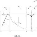
- FIG. 1Ais an exemplary illustration of a lithium-ion (Li-ion) battery charging profile
- FIG. 1Bis a capacity-voltage curve providing an exemplary illustration of Li-ion battery capacity as a function of a charging voltage and a charging current;
- FIG. 2is a schematic diagram of an exemplary wireless charging system, wherein a wireless charging station is configured to charge one or more wireless stations via one or more respective wireless radio frequency (RF) signals;
- RFradio frequency
- FIG. 3Ais a schematic diagram of an exemplary wireless charging circuit configured to control an effective charging power provided to a battery by providing a battery charging signal indication (BCSI) to the wireless charging station of FIG. 2 ;
- BCSIbattery charging signal indication
- FIG. 3Bis a schematic diagram of the exemplary wireless charging circuit of FIG. 3A that is coupled to a communication antenna and a wireless charging antenna;
- FIG. 4is a schematic diagram of an exemplary RF power harvesting circuit configured to turn a wireless RF charging signal received from the wireless charging station of FIG. 2 into a direct-current (DC) charging signal to charge the battery of FIG. 3A ;
- DCdirect-current
- FIG. 5illustrates an exemplary charging power reduction signal flow diagram for reducing the effective charging power of FIG. 3A when the effective charging power exceeds a target charging power required by the battery;
- FIG. 6illustrates an exemplary charging power increment signal flow diagram for increasing the effective charging power of FIG. 3A when the effective charging power falls short of the target charging power required by the battery;
- FIG. 7is a flowchart of an exemplary RF power adjustment process employed by the wireless charging station of FIG. 2 and the wireless charging circuit of FIG. 3A for adjusting the effective charging power based on the BCSI;
- FIG. 8is an exemplary power-versus-BCSI plot illustrating progressive adjustments to the effective charging power based on the BCSI
- FIG. 9is a schematic diagram of an exemplary RF front-end module (FEM) that is coupled to an antenna switch to transmit the BCSI of FIG. 3A on various RF spectrums of an industrial, scientific, and medical (ISM) band;
- FEMRF front-end module
- FIG. 10Ais a schematic diagram of an exemplary single-stage rectifier that may be provided in the RF power harvesting circuit of FIG. 4 ;
- FIG. 10Bis a schematic diagram of an exemplary differential single-stage rectifier that may be provided in the RF power harvesting circuit of FIG. 4 .
- a wireless radio frequency (RF) charging signal transmitted by a wireless charging stationis harvested and converted to a direct-current (DC) charging signal to charge a battery, for example, a lithium-ion (Li-ion) battery.
- RFradio frequency
- DCdirect-current
- an effective charging power in the DC charging signalis measured and compared to a target charging power required by the battery.
- a battery charging signal indication (BCSI)is provided to the wireless charging station to decrease the effective charging power if the effective charging power is greater than the target charging power.
- the BCSIis provided to the wireless charging station to increase the effective charging power if the effective charging power is less than the target charging power.
- FIGS. 1A and 1BBefore discussing the wireless charging concepts of the present disclosure, a brief overview of a Li-ion battery charging profile is provided with references to FIGS. 1A and 1B . The discussion of specific exemplary aspects of wireless charging starts below with reference to FIG. 2 .
- FIG. 1Ais an exemplary illustration of a Li-ion battery charging profile 10 .
- a Li-ion battery(not shown) has strict requirements on charging voltage and charging current because Li-ion cells (not shown) in the Li-ion battery cannot accept overcharge.
- the Li-ion batterycan only take what it can absorb. Anything extra can cause stress and even permanent damage to the Li-ion battery.
- the Li-ion batteryis in a ready stage 16 , wherein the Li-ion is charged to a desired voltage level and the charging current drops to zero (0).
- the effective charging poweralso drops to zero (0) to prevent overcharging damage to the Li-ion battery.
- the Li-ion batteryis in a standby stage 18 , wherein the charge current may be applied occasionally to top the Li-ion battery up to the desired voltage level.
- FIG. 1Bis a capacity-voltage curve 20 providing an exemplary illustration of a Li-ion battery capacity as a function of the charging voltage and the charging current of FIG. 1A .
- the capacity-voltage curve 20comprises a capacity curve 22 , a charging voltage curve 24 , and a charging current curve 26 .
- the charging voltage curve 24shoots up quickly.
- the Li-ion batteryis in the constant current stage 12 according to the Li-ion battery charging profile 10 of FIG. 1A .
- the charging current curve 26declines quickly and the charging voltage curve 24 levels off.
- the Li-ion batteryis in the saturation charge stage 14 according to the Li-ion battery charging profile 10 . Since the Li-ion battery cannot accept overcharge, the charging current must be cut off. A continuous trickle charge (maintenance charge) would cause plating of metallic lithium, thus compromising safety of the Li-ion battery.
- the effective charging powerincreases when the Li-ion battery is in the constant current stage 12 and decreases when the Li-ion battery is in the saturation charge stage 14 to ensure fast charging and protect the Li-ion battery from overcharging damage.
- the Li-ion batteryhas become increasingly popular in battery-operated electronic devices, such as smartphones, tablets, and portable computers, due to many advantages over traditional batteries (e.g., nickel-cadmium batteries).
- traditional batteriese.g., nickel-cadmium batteries
- the Li-ion batteryhas higher power density, produces less self-discharge, and requires lower maintenance to prolong battery life than the traditional batteries.
- wireless chargingis also gaining traction in the wireless communication industry and may one day replace charging plugs and wires, similar to how BLUETOOTHTM and wireless-fidelity (Wi-Fi) have eliminated communication cables (e.g., Ethernet cables) in peer-to-peer and peer-to-multi-peer communications.
- FIG. 2is a schematic diagram of an exemplary wireless charging system 28 , wherein a wireless charging station 30 is configured to charge one or more wireless stations 32 ( 1 )- 32 (N) via one or more respective wireless RF charging signals 34 ( 1 )- 34 (N).
- the one or more wireless stations 32 ( 1 )- 32 (N)comprise one or more respective batteries 36 ( 1 )- 36 (N).
- the one or more batteries 36 ( 1 )- 36 (N)are Li-ion batteries.
- the Li-ion battery charging profile 10 of FIG. 1A and the capacity-voltage curve 20 of FIG. 1Bare applicable when charging the one or more batteries 36 ( 1 )- 36 (N) in the wireless charging system 28 .
- the one or more wireless RF charging signals 34 ( 1 )- 34 (N)are provided on an industrial, scientific, and medical (ISM) band that may operate in nine hundred fifteen megahertz (915 MHz), twenty-four hundred megahertz (2400 MHz), fifty-eight hundred megahertz (5800 MHz), or twenty-four gigahertz (24 GHz) RF spectrums.
- ISMindustrial, scientific, and medical
- the wireless charging station 30has a total available power (referenced in drawings as P TOTAL ), which must be set below a maximum power (not shown) that is set by regulatory authorities such as the Federal Communications Commission (FCC) in the United States.
- the total available poweris shared among the one or more wireless stations 32 ( 1 )- 32 (N).
- the wireless charging station 30dynamically determines how the total available power is distributed among the one or more wireless stations 32 ( 1 )- 32 (N). In this regard, the more wireless stations that are in the wireless charging system 28 , the lesser share of the total available power each wireless station will receive.
- the wireless charging station 30comprises a plurality of antenna elements (not shown).
- the wireless charging station 30can have in excess of ten thousand (10,000) antenna elements.
- the plurality of antenna elements in the wireless charging station 30may be further configured to form one or more antenna arrays 38 ( 1 )- 38 (N), wherein each of one or more antenna arrays 38 ( 1 )- 38 (N) comprises at least two antenna elements among the plurality of antenna elements of the wireless charging station 30 .
- the one or more antenna arrays 38 ( 1 )- 38 (N)are configured to transmit the one more wireless RF charging signals 34 ( 1 )- 34 (N) to the one or more wireless stations 32 ( 1 )- 32 (N), respectively.
- wireless station 32 ( 1 ), wireless RF charging signal 34 ( 1 ), and antenna array 38 ( 1 )are discussed as a non-limiting example. It should be understood that the configuration and operation discussed herein are applicable to the one or more antenna arrays 38 ( 1 )- 38 (N), the one or more wireless RF charging signals 34 ( 1 )- 34 (N), and the one or more wireless stations 32 ( 1 )- 32 (N) as well.
- the wireless RF charging signal 34 ( 1 )will comprise four RF signals 42 ( 1 )- 42 ( 4 ) transmitted from the four antenna elements 40 ( 1 )- 40 ( 4 ), respectively.
- the wireless RF charging signal 34 ( 1 )is a beamformed wireless RF charging signal. Beamforming is a modern wireless signal transmission scheme, wherein multiple wireless signals, such as the four RF signals 42 ( 1 )- 42 ( 4 ), are transmitted simultaneously toward a single wireless receiver. If phases of the multiple wireless signals are coherent, the wireless receiver will be able to linearly combine the multiple wireless signals for improved signal strength and power gain.
- the four antenna elements 40 ( 1 )- 40 ( 4 ) in the antenna array 38 ( 1 )are calibrated to ensure phase coherence when the four RF signals 42 ( 1 )- 42 ( 4 ) arrive at the wireless station 32 ( 1 ).
- a total RF power (referenced in drawings as P RF ) of the wireless RF charging signal 34 ( 1 )can be linearly controlled by adjusting individual RF power of the four RF signals 42 ( 1 )- 42 (N). Hence, the total RF power of the wireless RF charging signal 34 ( 1 ) can be maximized.
- transmission phases and amplitudes of the four RF signals 42 ( 1 )- 42 ( 4 )can be estimated based on a training signal (not shown) provided by the wireless station 32 ( 1 ) under the assumption that the training signal would have a high degree of phase correlation with the wireless RF charging signal 34 ( 1 ).
- a training signalnot shown
- thismay not always be the case in the wireless charging system 28 because the antenna array 38 ( 1 ) and the wireless station 32 ( 1 ) may not always be disposed in the LOS arrangement.
- the estimated transmission phases and amplitudes based on the training signalmay be inaccurate.
- one or more battery charging signal indications (BCSIs) 44 ( 1 )- 44 (N)are provided by the one or more wireless stations 32 ( 1 )- 32 (N), respectively, to help control the effective charging power according to the Li-ion battery charging profile 10 .
- BCSI 44 ( 1 ) provided by the wireless station 32 ( 1 )indicates a difference between the effective charging power being provided to the battery 36 ( 1 ) and a target charging power (referenced in drawings as P TARGET ) determined based on the Li-ion battery charging profile 10 .
- the BCSI 44 ( 1 )is set to zero (0) when the effective charging power is greater than the target charging power to request a decrease of the total RF power in the wireless RF charging signal 34 ( 1 ).
- the BCSI 44 ( 1 )is set to one (1) when the effective charging power is less than the target charging power to request an increase of the total RF power in the wireless RF charging signal 34 ( 1 ).
- the wireless charging station 30Upon receiving the BCSI 44 ( 1 ), the wireless charging station 30 adjusts the individual RF power of the four RF signals 42 ( 1 )- 42 ( 4 ) accordingly. For example, the wireless charging station 30 can decrease the individual RF power of the four RF signals 42 ( 1 )- 42 ( 4 ) if the BCSI 44 ( 1 ) is set to zero (0), or increase the individual RF power of the four RF signals 42 ( 1 )- 42 ( 4 ) when the BCSI 44 ( 1 ) is set to one (1). Hence, by providing the BCSI 44 ( 1 ) to the wireless charging station 30 continuously or according to a predefined feedback schedule, the effective charging power provided to the battery 36 ( 1 ) can be gradually adjusted to eventually match the target charging power.
- FIG. 3Ais a schematic diagram of an exemplary wireless charging circuit 46 (X), which can be any of the one or more wireless charging circuits 46 ( 1 )- 46 (N) of FIG. 2 , configured to control the effective charging power by providing a BCSI 44 (X), from among the one or more BCSIs 44 ( 1 )- 44 (N), to the wireless charging station 30 .
- FIG. 2Elements of FIG. 2 are referenced in connection with FIG. 3A and will not be re-described herein.
- the wireless charging circuit 46 (X)may be provided in a battery-operated electronic device, such as a smartphone, a smartwatch, a tablet, a personal computer, a digital camera, a portable music player, a portable video player, a portable game player, a video recorder, and so on.
- a battery-operated electronic devicesuch as a smartphone, a smartwatch, a tablet, a personal computer, a digital camera, a portable music player, a portable video player, a portable game player, a video recorder, and so on.
- the wireless charging circuit 46 (X)comprises an RF power harvesting circuit 48 that is coupled to a battery 50 .
- the battery 50is a Li-ion battery and thus, obeys the Li-ion battery charging profile 10 of FIG. 1A .
- the RF power harvesting circuit 48which will be discussed later in FIG. 4 , is configured to receive a wireless RF charging signal 34 (X), which may be any of the one or more wireless RF charging signals 34 ( 1 )- 34 (N), and generate a DC charging signal 52 to charge the battery 50 .
- the DC charging signal 52is associated with an effective charging voltage (referenced in drawings as V EFF ) and an effective charging current that define the effective charging power.
- the effective charging poweris proportionally related to the total RF power received in the wireless RF charging signal 34 (X). Because the wireless charging station 30 must share the total available power among the one or more wireless stations 32 ( 1 )- 32 (N), the total RF power in the wireless RF charging signal 34 (X) can vary from time to time.
- the wireless charging circuit 46 (X)also comprises a wireless charging controller 54 that is configured to generate the BCSI 44 (X).
- the wireless charging controller 54receives a copy of the DC charging signal 52 ′, which indicates the effective charging power provided to the battery 50 by the RF power harvesting circuit 48 .
- the wireless charging controller 54also obtains a battery status reading 56 indicating the target charging power from the battery 50 .
- the wireless charging controller 54generates a BCSI feedback 58 based on a comparison between the effective charging power and the target charging power. In a non-limiting example, the BCSI feedback 58 is set to zero (0) if the effective charging power is greater than the target charging power. Conversely, the BCSI feedback 58 is set to one (1) if the effective charging power is less than the target charging power.
- the BCSI feedback 58is provided to a wireless communication system-on-chip (SoC) 60 wherein the BCSI feedback 58 is encoded into the BCSI 44 (X).
- the wireless communication SoC 60may also encode a received signal strength indicator (RSSI) of the wireless RF charging signal 34 (X) in the BCSI 44 (X).
- the wireless communication SoC 60may be a BLUETOOTH SoC, a Wi-Fi SoC, a ZigBee SoC, or a BLUETOOTH Low-Energy (BLE) SoC.
- the wireless charging controller 54 and the wireless communication SoC 60may be packaged into a wireless charging power control circuit 62 .
- the wireless charging controller 54may also be integrated into the wireless communication SoC 60 .
- the wireless charging controller 54may provide a first power decrease control signal 64 , a first power increase control signal 66 , a second power decrease control signal 68 , and a second power increase control signal 70 to adjust different elements in the RF power harvesting circuit 48 . More detailed descriptions regarding the adjustments to the RF power harvesting circuit 48 are provided later in FIG. 4 .
- the wireless communication SoC 60may receive and decode a downlink signal 72 to generate a charging control signal 74 .
- the charging control signal 74may comprise instructions from the wireless charging station 30 for adjusting the settings of the RF power harvesting circuit 48 .
- the wireless charging circuit 46 (X)is coupled to an antenna switch 76 , which is coupled to at least one antenna 78 .
- the at least one antenna 78is capable of emitting RF signals on the 910 MHz, the 2400 MHz, the 5800 MHz, and the 24 GHz RF spectrums of the ISM band.
- the antenna switch 76switches the at least one antenna 78 between receiving the wireless RF charging signal 34 (X), transmitting the BCSI 44 (X), and receiving the downlink signal 72 according to a time-division arrangement.
- FIG. 3Bis a schematic diagram of the exemplary wireless charging circuit 46 (X) of FIG. 3A that is coupled to a communication antenna 80 and a wireless charging antenna 82 .
- FIGS. 3A and 3BCommon elements between FIGS. 3A and 3B are shown therein with common element numbers, and thus will not be re-described herein.
- the wireless charging antenna 82dedicated to receiving the wireless RF charging signal 34 (X)
- FIG. 4is a schematic diagram of the RF power harvesting circuit 48 of FIG. 3A configured to turn the wireless RF charging signal 34 (X) into the DC charging signal 52 to charge the battery 50 .
- Elements of FIG. 3Aare referenced in connection with FIG. 4 and will not be re-described herein.
- the RF power harvesting circuit 48comprises an RF tuner 84 , an RF rectifier 86 , and a DC-to-DC (DC-DC) converter 88 .
- the RF tuner 84has an input impedance (referenced in drawings as Z RF_IN ).
- An impedance transformation circuitry 90is provided in the RF power harvesting circuit 48 to provide a load-line impedance (referenced in drawings as Z LOAD ).
- the impedance transformation circuitry 90may be integrated with the RF rectifier 86 .
- the RF power harvesting circuit 48may be integrated into an integrated circuit (IC).
- the RF tuner 84receives the wireless RF charging signal 34 (X) from the wireless charging station 30 of FIG. 2 . According to previous discussion in FIG. 3A , the wireless RF charging signal 34 (X) carries the total RF power.
- the RF tuner 84generates an alternating current (AC) charging signal 92 based on the wireless RF charging signal 34 (X).
- the AC charging signal 92has a respective RF power (referenced in drawings as P′ RF ) and a respective voltage (referenced in drawings as V′ RF ) that is influenced by the load-line impedance. The respective RF power in the AC charging signal 92 is maximized when the load-line impedance matches the input impedance.
- the load-line impedancemismatches the input impedance, the respective RF power in the AC charging signal 92 is less than the total RF power of the wireless RF charging signal 34 (X) due to signal reflection. Further, if the load-line impedance is substantially higher than the input impedance, the respective voltage of the AC charging signal 92 is maximized, even though the respective RF power is less than the maximum power. As such, the load-line impedance may be manipulated to influence the efficiency of the RF rectifier 86 , and thus controlling the effective charging power of the DC charging signal 52 .
- the wireless charging controller 54when the wireless charging controller 54 (not shown) determines that the effective charging power is greater than the target charging power, the wireless charging controller 54 can provide the first power decrease control signal 64 to the impedance transformation circuitry 90 in addition to sending the BCSI 44 (X) to the wireless charging station 30 .
- the first power decrease control signal 64causes the load-line impedance to mismatch the input impedance, thus reducing the respective RF power and, consequently, the effective charging power.
- the wireless charging controller 54can provide the first power increase control signal 66 to the impedance transformation circuitry 90 in addition to sending the BCSI 44 (X) to the wireless charging station 30 .
- the first power increase control signal 66causes the load-line impedance to be substantially higher than the input impedance, thus increasing the respective voltage applied to the RF rectifier 86 and thus, controlling the effective charging power.
- the RF rectifier 86receives and converts the AC charging signal 92 into a DC signal 94 having a first DC voltage (sometimes referred to as V DC1 ).
- the RF rectifier 86may be a single-stage rectifier or a differential single-stage rectifier.
- the RF power harvesting circuit 48also comprises a tunable capacitor 96 coupled between the RF rectifier 86 and the DC-DC converter 88 , wherein the tunable capacitor 96 is configured to remove voltage fluctuations in the DC signal 94 .
- the DC-DC converter 88is configured to up-convert the first DC voltage into a second DC voltage (sometimes referred to as V DC2 ), which is the same as the effective charging voltage in the DC charging signal 52 for charging the battery 50 .
- V DC2a second DC voltage
- the DC-DC converter 88may be a Buck-Boost DC-DC converter.
- the second DC voltagecan be increased or decreased by increasing or decreasing the duty-cycle of the DC-DC converter 88 .
- the effective charging poweris influenced by the effective charging voltage and the effective charging current associated with the DC charging signal 52 . As such, when the effective charging current is held steady, increasing or decreasing the second DC voltage will lead to an increase or decrease of the effective charging voltage provided to the battery 50 .
- the wireless charging controller 54may provide the second power decrease control signal 68 to the DC-DC converter 88 in addition to sending the BCSI 44 (X) to the wireless charging station 30 .
- the second power decrease control signal 68decreases the duty-cycle of the DC-DC converter 88 , thus reducing the second DC voltage and, consequently, the effective charging power.
- the wireless charging controller 54may provide the second power increase control signal 70 to the DC-DC converter 88 in addition to sending the BCSI 44 (X) to the wireless charging station 30 .
- the second power increase control signal 70increases the duty-cycle of the DC-DC converter 88 , thus increasing the second DC voltage and, consequently, the effective charging power.
- FIGS. 5 and 6are provided. Common elements between FIGS. 2, 3A, 4, 5, and 6 are shown therein with common element numbers and thus, will not be re-described herein.
- FIG. 5illustrates an exemplary charging power reduction signal flow diagram 98 for reducing the effective charging power when the effective charging power exceeds the target charging power required by the battery 50 .
- the wireless charging controller 54receives the battery status reading 56 , which indicates the target charging power requested by the battery 50 .
- the wireless charging controller 54also receives the copy of the DC charging signal 52 ′, which indicates the effective charging power provided to the battery 50 . If the wireless charging controller 54 determines that the effective charging power is greater than the target charging power, the wireless charging controller 54 sends the BCSI 44 (X), which is set to zero (0), to the wireless charging station 30 to request that the total RF power be reduced.
- the wireless charging station 30may provide the charging control signal 74 with instructions for adjusting the settings of the RF power harvesting circuit 48 .
- the wireless charging controller 54is able to reduce the duty-cycle of the DC-DC converter 88 and/or adjust the load-line impedance of the impedance transformation circuitry 90 to reduce the effective charging power.
- the wireless charging controller 54may determine the duty-cycle and/or the load-line impedance according to internal algorithms or based on the instructions received with the charging control signal 74 .
- the wireless charging controller 54then provides the first power decrease control signal 64 and the second power decrease control signal 68 to the impedance transformation circuitry 90 and the DC-DC converter 88 to adjust the load-line impedance and the duty-cycle, respectively.
- FIG. 6illustrates an exemplary charging power increment signal flow diagram 100 for increasing the effective charging power when the effective charging power falls short of the target charging power required by the battery 50 .
- the wireless charging controller 54receives the battery status reading 56 , which indicates the target charging power requested by the battery 50 .
- the wireless charging controller 54also receives the copy of the DC charging signal 52 ′, which indicates the effective charging power provided to the battery 50 . If the wireless charging controller 54 determines that the effective charging power is less than the target charging power, the wireless charging controller 54 sends the BCSI 44 (X), which is set to one (1), to the wireless charging station 30 to request that the total RF power be increased.
- the wireless charging station 30may provide the charging control signal 74 with instructions for adjusting the settings of the RF power harvesting circuit 48 .
- the wireless charging controller 54is able to increase the duty-cycle of the DC-DC converter 88 and/or adjust the load-line impedance of the impedance transformation circuitry 90 to increase the effective charging power.
- the wireless charging controller 54may determine the duty-cycle and/or the load-line impedance according to internal algorithms or based on the instructions received from the charging control signal 74 .
- the wireless charging controller 54then provides the first power increase control signal 66 and the second power increase control signal 70 to the impedance transformation circuitry 90 and the DC-DC converter 88 to adjust the load-line impedance and the duty-cycle, respectively.
- the wireless charging controller 54requests the wireless charging station 30 to decrease or increase the total RF power, and consequently the effective charging power, in the wireless RF charging signal 34 (X) by setting the BCSI 44 (X) to zero (0) or one (1).
- the wireless charging controller 54is unable to provide precise indication in the BCSI 44 (X) with regard to how much the wireless charging station 30 needs to decrease or increase the total RF power. As such, adjustment of the total RF power based on the BCSI 44 (X) must be performed progressively by the wireless charging station 30 and the wireless charging controller 54 .
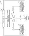
- FIG. 7is a flowchart of an exemplary RF power adjustment process 102 employed by the wireless charging station 30 and the wireless charging circuit 46 (X) for adjusting the effective charging power based on the BCSI 44 (X). Elements of FIG. 3A are referenced in connection with FIG. 7 and will not be re-described herein.
- the wireless charging controller 54(not shown) in the wireless charging circuit 46 (X) (not shown) receives the target charging power requested by the battery 50 (not shown) in the battery status reading 56 (block 104 ).
- the wireless charging controller 54also receives the effective charging power provided to the battery 50 in the copy of the DC charging signal 52 ′ (block 106 ).
- the wireless charging controller 54then compares the effective charging power and the target charging power (block 108 ). If the effective charging power is greater than the target charging power, the wireless charging controller 54 sends the BCSI 44 (X), which is set to zero (0), to request the wireless charging station 30 to reduce the total RF power in the wireless RF charging signal 34 (X) (block 110 ).
- the wireless charging controller 54sends the BCSI 44 (X), which is set to one (1), to request the wireless charging station 30 to increase the total RF power in the wireless RF charging signal 34 (X) (block 112 ).
- the wireless charging station 30either decreases or increases the total RF power in response to receiving the BCSI 44 (X).
- the wireless charging station 30may decide the amount of decrease or increase of the total RF power based on the total available power and how many of the one or more wireless stations 32 ( 1 )- 32 (N) are charged by the wireless charging station 30 .
- the wireless charging controller 54continues sending the BCSI 44 (X), which is set to either zero (0) or one (1), until the effective charging power is equal to the target charging power (block 114 ).
- FIG. 8is an exemplary power-versus-BCSI plot 116 illustrating progressive adjustments to the effective charging power based on the BCSI 44 (X).
- the power-versus-BCSI plot 116comprises a maximum power (referenced in drawings as P MAX ) curve 118 , a total available power curve 120 , a total RF power curve 122 , a target charging power curve 124 , and an effective charging power curve 126 .
- P MAXmaximum power
- Exemplary power figuresare cited herein for illustrative purposes and are not meant to be interpreted as limiting. Elements of FIGS. 2 and 3A are referenced in connection with FIG. 8 and will not be re-described herein.
- the maximum power the wireless charging station 30 is allowed to transmitis three watts (3 W).
- the total available poweras shown in the total available power curve 120 , is less than or equal to the maximum power and is shared by the one or more wireless stations 32 ( 1 )- 32 (N).
- the total RF power curve 122illustrates fluctuations of the total RF power of the wireless RF charging signal 34 (X). The fluctuations of the total RF power may be caused by sharing the total available power among the one or more wireless stations 32 ( 1 )- 32 (N), and/or power adjustments by the wireless charging station 30 in response to the BCSI 44 (X).
- the total RF power in the wireless RF charging signal 34 (X)is three hundred milliwatts (300 mW).
- the target charging power requested by the battery 50 and the effective charging power provided to the battery 50are one hundred and ten milliwatts (110 mW) and two hundred milliwatts (200 mW), respectively.
- the wireless charging circuit 46 (X)sends the BCSI 44 (X), which is set to zero (0), to request the wireless charging station 30 to reduce the effective charging power.
- the wireless charging circuit 46 (X)may also reduce the effective charging power by adjusting the duty-cycle and/or the load-line impedance, as previously discussed in reference to FIG. 4 .
- the total RF poweris reduced to two hundred and fifty milliwatts (250 mW). Accordingly, the effective charging power is reduced from 200 mW to one hundred and fifty milliwatts (150 mW). Since the effective charging power is still higher than the target charging power, the wireless charging circuit 46 (X) resends the BCSI 44 (X), which is set to zero (0), to request the wireless charging station 30 to further reduce the effective charging power.
- the total RF poweris reduced to 200 mW and the effective charging power is reduced from 150 mW to 110 mW.
- the effective charging poweris equal to the target charging power and the wireless charging circuit 46 (X) will not send the BCSI 44 (X) to the wireless charging station 30 .
- the total RF powerdrops to one hundred milliwatts (100 mW), which may be caused by the wireless charging station 30 sharing the total available power with more of the one or more wireless stations 32 ( 1 )- 32 (N). Consequently, the effective charging power drops to 100 mW and is less than the target charging power of 110 mW.
- the wireless charging circuit 46 (X)sends the BCSI 44 (X), which is set to one (1), to request the wireless charging station 30 to increase the effective charging power.
- the wireless charging circuit 46 (X)may also increase the effective charging power by adjusting the duty-cycle and/or the load-line impedance, as previously discussed in reference to FIG. 4 .
- the wireless charging circuit 46 (X)again sends the BCSI 44 (X), which is set to zero (0), to request the wireless charging station 30 to reduce the effective charging power.
- the wireless charging circuit 46 (X)sends the BCSI 44 (X), which is set to one (1), to request the wireless charging station 30 to increase the effective charging power.
- the wireless charging circuit 46 (X)sends the BCSI 44 (X), which is set to one (1), to request the wireless charging station 30 to increase the effective charging power.
- the total RF power, the effective charging power, and the target charging powerare all at 150 mW. Therefore, there is no need to request the wireless charging station 30 to adjust the effective charging power.
- FIG. 9is a schematic diagram of an exemplary RF front-end module (FEM) 128 that is coupled to the antenna switch 76 to transmit the BCSI 44 (X) on various RF spectrums of the ISM band.
- FEMRF front-end module
- the BCSI feedback 58is first converted into a digital BCSI feedback 130 by an analog-to-digital converter (ADC) 132 before being encoded by the wireless communication SoC 60 to generate the BCSI 44 (X).
- the BCSI 44 (X)is received by an RF mixer 134 and modulated onto one of the four RF spectrums, namely 910 MHz, 2400 MHz, 5800 MHz, and 24 GHz, of the ISM band.
- the RF mixer 134modulates the BCSI 44 (X) based on a modulation signal 136 that is provided by an RF synthesizer 138 .
- the RF FEM 128comprises a first RF path 140 , a second RF path 142 , a third RF path 144 , and a fourth RF path 145 that correspond to the 910 MHz, the 2400 MHz, the 5800 MHz, and the 24 GHz RF spectrum, respectively.
- the first RF path 140comprises a first RF amplifier 146 and a first RF filter 148 .
- the second RF path 142comprises a second RF amplifier 150 and a second RF filter 152 .
- the third RF path 144comprises a third RF amplifier 154 and a third RF filter 156 .
- the fourth RF path 145comprises a fourth RF amplifier 157 and a fourth RF filter 158 .
- the first RF path 140 , the second RF path 142 , and the third RF path 144are coupled to a first coupling point 159 , a second coupling point 160 , a third coupling point 162 , and a fourth coupling point 163 in the antenna switch 76 , respectively.
- the antenna switch 76couples the first RF path 140 to the at least one antenna 78 to transmit the BCSI 44 (X) on the 910 MHz RF spectrum.
- the antenna switch 76couples the second RF path 142 to the at least one antenna 78 to transmit the BCSI 44 (X) on the 2400 MHz RF spectrum.
- the antenna switch 76couples the third RF path 144 to the at least one antenna 78 to transmit the BCSI 44 (X) on the 5800 MHz RF spectrum.
- the antenna switch 76couples the fourth RF path 145 to the at least one antenna 78 to transmit the BCSI 44 (X) on the 24 GHz RF spectrum.
- the RF rectifier 86may be a single-stage rectifier or a differential single-stage rectifier.
- FIG. 10Ais a schematic diagram of an exemplary single-stage rectifier 164 that may be provided in the RF power harvesting circuit 48 of FIG. 4 . Elements of FIG. 4 are referenced in connection with FIG. 10A and will not be re-described herein.
- the single-stage rectifier 164receives the AC charging signal 92 as an input.
- the AC charging signal 92has a transferred RF power and a transferred voltage.
- the transferred RF power and the transferred voltageare applied to the single-stage rectifier 164 as an input power (referenced in drawings as P IN ) and a forward voltage (referenced in drawings as V F ), respectively.
- the single-stage rectifier 164comprises a resistor 166 and an inductor 168 .
- the resistor 166 and the inductor 168provide the load-line impedance.
- the single-stage rectifier 164comprises a first capacitor 170 and a second capacitor 172 .
- the single-stage rectifier 164also comprises a first diode 174 and a second diode 176 .
- the first diode 174 and the second diode 176can be Schottky diodes.
- the first diode 174 and the second diode 176receive a DC load current (referenced in drawings as I DC_LOAD ) and a diode voltage (referenced in drawings as V BE ) associated with the DC load current.
- the first capacitor 170 , the second capacitor 172 , the first diode 174 , and the second diode 176are configured to convert an input current (referenced in drawings as I IN ), which is an AC, into the DC load current.
- the single-stage rectifier 164generates the DC signal 94 .
- the DC signal 94has an output power (sometimes referred to as P OUT ) and is associated with the first DC voltage.
- FIG. 10Bis a schematic diagram of an exemplary differential single-stage rectifier 178 that may be provided in the RF power harvesting circuit 48 of FIG. 4 .
- FIGS. 10A and 10BCommon elements between FIGS. 10A and 10B are shown therein with common element numbers and thus, will not be re-described herein.
- the differential single-stage rectifier 178comprises a first branch 180 and a second branch 182 .
- Each of the first branch 180 and the second branch 182can function individually as the single-stage rectifier 164 of FIG. 10A .
- a transformation switch 184may be controlled by the first power decrease control signal 64 or the first power increase control signal 66 of FIG. 4 to adjust the load-line impedance of the differential single-stage rectifier 178 .
- both the first branch 180 and the second branch 182are coupled to the inductor 168 , thus increasing the load-line impedance.
- the transformation switch 184is closed, the second branch 182 is short circuited.
Landscapes
- Engineering & Computer Science (AREA)
- Power Engineering (AREA)
- Computer Networks & Wireless Communication (AREA)
- Charge And Discharge Circuits For Batteries Or The Like (AREA)
Abstract
Description
Claims (18)
Priority Applications (1)
| Application Number | Priority Date | Filing Date | Title |
|---|---|---|---|
| US14/792,933US10559970B2 (en) | 2014-09-16 | 2015-07-07 | Method for wireless charging power control |
Applications Claiming Priority (2)
| Application Number | Priority Date | Filing Date | Title |
|---|---|---|---|
| US201462051023P | 2014-09-16 | 2014-09-16 | |
| US14/792,933US10559970B2 (en) | 2014-09-16 | 2015-07-07 | Method for wireless charging power control |
Publications (2)
| Publication Number | Publication Date |
|---|---|
| US20160079799A1 US20160079799A1 (en) | 2016-03-17 |
| US10559970B2true US10559970B2 (en) | 2020-02-11 |
Family
ID=55455762
Family Applications (1)
| Application Number | Title | Priority Date | Filing Date |
|---|---|---|---|
| US14/792,933Active2035-11-19US10559970B2 (en) | 2014-09-16 | 2015-07-07 | Method for wireless charging power control |
Country Status (1)
| Country | Link |
|---|---|
| US (1) | US10559970B2 (en) |
Families Citing this family (199)
| Publication number | Priority date | Publication date | Assignee | Title |
|---|---|---|---|---|
| US9094054B2 (en)* | 2009-11-30 | 2015-07-28 | Broadcom Corporation | IC controlled wireless power operation and applications thereof including control channel communication configuration |
| US9954374B1 (en) | 2014-05-23 | 2018-04-24 | Energous Corporation | System and method for self-system analysis for detecting a fault in a wireless power transmission Network |
| US9923386B1 (en) | 2012-07-06 | 2018-03-20 | Energous Corporation | Systems and methods for wireless power transmission by modifying a number of antenna elements used to transmit power waves to a receiver |
| US9876394B1 (en) | 2014-05-07 | 2018-01-23 | Energous Corporation | Boost-charger-boost system for enhanced power delivery |
| US9887739B2 (en) | 2012-07-06 | 2018-02-06 | Energous Corporation | Systems and methods for wireless power transmission by comparing voltage levels associated with power waves transmitted by antennas of a plurality of antennas of a transmitter to determine appropriate phase adjustments for the power waves |
| US20150326070A1 (en) | 2014-05-07 | 2015-11-12 | Energous Corporation | Methods and Systems for Maximum Power Point Transfer in Receivers |
| US20140008993A1 (en) | 2012-07-06 | 2014-01-09 | DvineWave Inc. | Methodology for pocket-forming |
| US9438045B1 (en) | 2013-05-10 | 2016-09-06 | Energous Corporation | Methods and systems for maximum power point transfer in receivers |
| US10224982B1 (en) | 2013-07-11 | 2019-03-05 | Energous Corporation | Wireless power transmitters for transmitting wireless power and tracking whether wireless power receivers are within authorized locations |
| US10063105B2 (en) | 2013-07-11 | 2018-08-28 | Energous Corporation | Proximity transmitters for wireless power charging systems |
| US10211680B2 (en) | 2013-07-19 | 2019-02-19 | Energous Corporation | Method for 3 dimensional pocket-forming |
| US9831718B2 (en) | 2013-07-25 | 2017-11-28 | Energous Corporation | TV with integrated wireless power transmitter |
| US11502551B2 (en) | 2012-07-06 | 2022-11-15 | Energous Corporation | Wirelessly charging multiple wireless-power receivers using different subsets of an antenna array to focus energy at different locations |
| US9891669B2 (en) | 2014-08-21 | 2018-02-13 | Energous Corporation | Systems and methods for a configuration web service to provide configuration of a wireless power transmitter within a wireless power transmission system |
| US9893768B2 (en) | 2012-07-06 | 2018-02-13 | Energous Corporation | Methodology for multiple pocket-forming |
| US9368020B1 (en) | 2013-05-10 | 2016-06-14 | Energous Corporation | Off-premises alert system and method for wireless power receivers in a wireless power network |
| US9948135B2 (en) | 2015-09-22 | 2018-04-17 | Energous Corporation | Systems and methods for identifying sensitive objects in a wireless charging transmission field |
| US9843213B2 (en) | 2013-08-06 | 2017-12-12 | Energous Corporation | Social power sharing for mobile devices based on pocket-forming |
| US9853692B1 (en) | 2014-05-23 | 2017-12-26 | Energous Corporation | Systems and methods for wireless power transmission |
| US9991741B1 (en) | 2014-07-14 | 2018-06-05 | Energous Corporation | System for tracking and reporting status and usage information in a wireless power management system |
| US10256657B2 (en) | 2015-12-24 | 2019-04-09 | Energous Corporation | Antenna having coaxial structure for near field wireless power charging |
| US9825674B1 (en) | 2014-05-23 | 2017-11-21 | Energous Corporation | Enhanced transmitter that selects configurations of antenna elements for performing wireless power transmission and receiving functions |
| US9143000B2 (en) | 2012-07-06 | 2015-09-22 | Energous Corporation | Portable wireless charging pad |
| US10992187B2 (en) | 2012-07-06 | 2021-04-27 | Energous Corporation | System and methods of using electromagnetic waves to wirelessly deliver power to electronic devices |
| US9887584B1 (en) | 2014-08-21 | 2018-02-06 | Energous Corporation | Systems and methods for a configuration web service to provide configuration of a wireless power transmitter within a wireless power transmission system |
| US10263432B1 (en) | 2013-06-25 | 2019-04-16 | Energous Corporation | Multi-mode transmitter with an antenna array for delivering wireless power and providing Wi-Fi access |
| US10230266B1 (en) | 2014-02-06 | 2019-03-12 | Energous Corporation | Wireless power receivers that communicate status data indicating wireless power transmission effectiveness with a transmitter using a built-in communications component of a mobile device, and methods of use thereof |
| US10211674B1 (en) | 2013-06-12 | 2019-02-19 | Energous Corporation | Wireless charging using selected reflectors |
| US9882427B2 (en) | 2013-05-10 | 2018-01-30 | Energous Corporation | Wireless power delivery using a base station to control operations of a plurality of wireless power transmitters |
| US9824815B2 (en) | 2013-05-10 | 2017-11-21 | Energous Corporation | Wireless charging and powering of healthcare gadgets and sensors |
| US9847677B1 (en) | 2013-10-10 | 2017-12-19 | Energous Corporation | Wireless charging and powering of healthcare gadgets and sensors |
| US9787103B1 (en) | 2013-08-06 | 2017-10-10 | Energous Corporation | Systems and methods for wirelessly delivering power to electronic devices that are unable to communicate with a transmitter |
| US10199835B2 (en) | 2015-12-29 | 2019-02-05 | Energous Corporation | Radar motion detection using stepped frequency in wireless power transmission system |
| US9941747B2 (en) | 2014-07-14 | 2018-04-10 | Energous Corporation | System and method for manually selecting and deselecting devices to charge in a wireless power network |
| US10038337B1 (en) | 2013-09-16 | 2018-07-31 | Energous Corporation | Wireless power supply for rescue devices |
| US9812890B1 (en) | 2013-07-11 | 2017-11-07 | Energous Corporation | Portable wireless charging pad |
| US9838083B2 (en) | 2014-07-21 | 2017-12-05 | Energous Corporation | Systems and methods for communication with remote management systems |
| US9847679B2 (en) | 2014-05-07 | 2017-12-19 | Energous Corporation | System and method for controlling communication between wireless power transmitter managers |
| US9859756B2 (en) | 2012-07-06 | 2018-01-02 | Energous Corporation | Transmittersand methods for adjusting wireless power transmission based on information from receivers |
| US10141768B2 (en) | 2013-06-03 | 2018-11-27 | Energous Corporation | Systems and methods for maximizing wireless power transfer efficiency by instructing a user to change a receiver device's position |
| US9882430B1 (en) | 2014-05-07 | 2018-01-30 | Energous Corporation | Cluster management of transmitters in a wireless power transmission system |
| US9876379B1 (en) | 2013-07-11 | 2018-01-23 | Energous Corporation | Wireless charging and powering of electronic devices in a vehicle |
| US10148097B1 (en) | 2013-11-08 | 2018-12-04 | Energous Corporation | Systems and methods for using a predetermined number of communication channels of a wireless power transmitter to communicate with different wireless power receivers |
| US9871398B1 (en) | 2013-07-01 | 2018-01-16 | Energous Corporation | Hybrid charging method for wireless power transmission based on pocket-forming |
| US9941707B1 (en) | 2013-07-19 | 2018-04-10 | Energous Corporation | Home base station for multiple room coverage with multiple transmitters |
| US10992185B2 (en) | 2012-07-06 | 2021-04-27 | Energous Corporation | Systems and methods of using electromagnetic waves to wirelessly deliver power to game controllers |
| US10206185B2 (en) | 2013-05-10 | 2019-02-12 | Energous Corporation | System and methods for wireless power transmission to an electronic device in accordance with user-defined restrictions |
| US9252628B2 (en) | 2013-05-10 | 2016-02-02 | Energous Corporation | Laptop computer as a transmitter for wireless charging |
| US10291066B1 (en) | 2014-05-07 | 2019-05-14 | Energous Corporation | Power transmission control systems and methods |
| US10211682B2 (en) | 2014-05-07 | 2019-02-19 | Energous Corporation | Systems and methods for controlling operation of a transmitter of a wireless power network based on user instructions received from an authenticated computing device powered or charged by a receiver of the wireless power network |
| US9859757B1 (en) | 2013-07-25 | 2018-01-02 | Energous Corporation | Antenna tile arrangements in electronic device enclosures |
| US9876648B2 (en) | 2014-08-21 | 2018-01-23 | Energous Corporation | System and method to control a wireless power transmission system by configuration of wireless power transmission control parameters |
| US10075008B1 (en) | 2014-07-14 | 2018-09-11 | Energous Corporation | Systems and methods for manually adjusting when receiving electronic devices are scheduled to receive wirelessly delivered power from a wireless power transmitter in a wireless power network |
| US9793758B2 (en) | 2014-05-23 | 2017-10-17 | Energous Corporation | Enhanced transmitter using frequency control for wireless power transmission |
| US10439448B2 (en) | 2014-08-21 | 2019-10-08 | Energous Corporation | Systems and methods for automatically testing the communication between wireless power transmitter and wireless power receiver |
| US10381880B2 (en) | 2014-07-21 | 2019-08-13 | Energous Corporation | Integrated antenna structure arrays for wireless power transmission |
| US10128699B2 (en) | 2014-07-14 | 2018-11-13 | Energous Corporation | Systems and methods of providing wireless power using receiver device sensor inputs |
| US10090886B1 (en) | 2014-07-14 | 2018-10-02 | Energous Corporation | System and method for enabling automatic charging schedules in a wireless power network to one or more devices |
| US9859797B1 (en) | 2014-05-07 | 2018-01-02 | Energous Corporation | Synchronous rectifier design for wireless power receiver |
| US10141791B2 (en) | 2014-05-07 | 2018-11-27 | Energous Corporation | Systems and methods for controlling communications during wireless transmission of power using application programming interfaces |
| US10224758B2 (en) | 2013-05-10 | 2019-03-05 | Energous Corporation | Wireless powering of electronic devices with selective delivery range |
| US10124754B1 (en) | 2013-07-19 | 2018-11-13 | Energous Corporation | Wireless charging and powering of electronic sensors in a vehicle |
| US9124125B2 (en) | 2013-05-10 | 2015-09-01 | Energous Corporation | Wireless power transmission with selective range |
| US9806564B2 (en) | 2014-05-07 | 2017-10-31 | Energous Corporation | Integrated rectifier and boost converter for wireless power transmission |
| US9899861B1 (en) | 2013-10-10 | 2018-02-20 | Energous Corporation | Wireless charging methods and systems for game controllers, based on pocket-forming |
| US12057715B2 (en) | 2012-07-06 | 2024-08-06 | Energous Corporation | Systems and methods of wirelessly delivering power to a wireless-power receiver device in response to a change of orientation of the wireless-power receiver device |
| US9912199B2 (en) | 2012-07-06 | 2018-03-06 | Energous Corporation | Receivers for wireless power transmission |
| US9900057B2 (en) | 2012-07-06 | 2018-02-20 | Energous Corporation | Systems and methods for assigning groups of antenas of a wireless power transmitter to different wireless power receivers, and determining effective phases to use for wirelessly transmitting power using the assigned groups of antennas |
| US10965164B2 (en) | 2012-07-06 | 2021-03-30 | Energous Corporation | Systems and methods of wirelessly delivering power to a receiver device |
| US10063106B2 (en) | 2014-05-23 | 2018-08-28 | Energous Corporation | System and method for a self-system analysis in a wireless power transmission network |
| US10050462B1 (en) | 2013-08-06 | 2018-08-14 | Energous Corporation | Social power sharing for mobile devices based on pocket-forming |
| US9966765B1 (en) | 2013-06-25 | 2018-05-08 | Energous Corporation | Multi-mode transmitter |
| US9843201B1 (en) | 2012-07-06 | 2017-12-12 | Energous Corporation | Wireless power transmitter that selects antenna sets for transmitting wireless power to a receiver based on location of the receiver, and methods of use thereof |
| US10063064B1 (en) | 2014-05-23 | 2018-08-28 | Energous Corporation | System and method for generating a power receiver identifier in a wireless power network |
| US9867062B1 (en) | 2014-07-21 | 2018-01-09 | Energous Corporation | System and methods for using a remote server to authorize a receiving device that has requested wireless power and to determine whether another receiving device should request wireless power in a wireless power transmission system |
| US10243414B1 (en) | 2014-05-07 | 2019-03-26 | Energous Corporation | Wearable device with wireless power and payload receiver |
| US10218227B2 (en) | 2014-05-07 | 2019-02-26 | Energous Corporation | Compact PIFA antenna |
| US9941754B2 (en) | 2012-07-06 | 2018-04-10 | Energous Corporation | Wireless power transmission with selective range |
| US10186913B2 (en) | 2012-07-06 | 2019-01-22 | Energous Corporation | System and methods for pocket-forming based on constructive and destructive interferences to power one or more wireless power receivers using a wireless power transmitter including a plurality of antennas |
| US10128693B2 (en) | 2014-07-14 | 2018-11-13 | Energous Corporation | System and method for providing health safety in a wireless power transmission system |
| US9939864B1 (en) | 2014-08-21 | 2018-04-10 | Energous Corporation | System and method to control a wireless power transmission system by configuration of wireless power transmission control parameters |
| US9906065B2 (en) | 2012-07-06 | 2018-02-27 | Energous Corporation | Systems and methods of transmitting power transmission waves based on signals received at first and second subsets of a transmitter's antenna array |
| US9899873B2 (en) | 2014-05-23 | 2018-02-20 | Energous Corporation | System and method for generating a power receiver identifier in a wireless power network |
| US9893554B2 (en) | 2014-07-14 | 2018-02-13 | Energous Corporation | System and method for providing health safety in a wireless power transmission system |
| US10193396B1 (en) | 2014-05-07 | 2019-01-29 | Energous Corporation | Cluster management of transmitters in a wireless power transmission system |
| US9973021B2 (en) | 2012-07-06 | 2018-05-15 | Energous Corporation | Receivers for wireless power transmission |
| US10270261B2 (en) | 2015-09-16 | 2019-04-23 | Energous Corporation | Systems and methods of object detection in wireless power charging systems |
| US10291055B1 (en) | 2014-12-29 | 2019-05-14 | Energous Corporation | Systems and methods for controlling far-field wireless power transmission based on battery power levels of a receiving device |
| US10312715B2 (en) | 2015-09-16 | 2019-06-04 | Energous Corporation | Systems and methods for wireless power charging |
| US10090699B1 (en) | 2013-11-01 | 2018-10-02 | Energous Corporation | Wireless powered house |
| US9853458B1 (en) | 2014-05-07 | 2017-12-26 | Energous Corporation | Systems and methods for device and power receiver pairing |
| US10008889B2 (en) | 2014-08-21 | 2018-06-26 | Energous Corporation | Method for automatically testing the operational status of a wireless power receiver in a wireless power transmission system |
| US10199849B1 (en) | 2014-08-21 | 2019-02-05 | Energous Corporation | Method for automatically testing the operational status of a wireless power receiver in a wireless power transmission system |
| US10103582B2 (en) | 2012-07-06 | 2018-10-16 | Energous Corporation | Transmitters for wireless power transmission |
| US9893555B1 (en) | 2013-10-10 | 2018-02-13 | Energous Corporation | Wireless charging of tools using a toolbox transmitter |
| US10223717B1 (en) | 2014-05-23 | 2019-03-05 | Energous Corporation | Systems and methods for payment-based authorization of wireless power transmission service |
| US10205239B1 (en) | 2014-05-07 | 2019-02-12 | Energous Corporation | Compact PIFA antenna |
| US9537357B2 (en) | 2013-05-10 | 2017-01-03 | Energous Corporation | Wireless sound charging methods and systems for game controllers, based on pocket-forming |
| US9538382B2 (en) | 2013-05-10 | 2017-01-03 | Energous Corporation | System and method for smart registration of wireless power receivers in a wireless power network |
| US9419443B2 (en) | 2013-05-10 | 2016-08-16 | Energous Corporation | Transducer sound arrangement for pocket-forming |
| US9866279B2 (en) | 2013-05-10 | 2018-01-09 | Energous Corporation | Systems and methods for selecting which power transmitter should deliver wireless power to a receiving device in a wireless power delivery network |
| US9819230B2 (en) | 2014-05-07 | 2017-11-14 | Energous Corporation | Enhanced receiver for wireless power transmission |
| US10103552B1 (en) | 2013-06-03 | 2018-10-16 | Energous Corporation | Protocols for authenticated wireless power transmission |
| US10003211B1 (en) | 2013-06-17 | 2018-06-19 | Energous Corporation | Battery life of portable electronic devices |
| US10021523B2 (en) | 2013-07-11 | 2018-07-10 | Energous Corporation | Proximity transmitters for wireless power charging systems |
| US9979440B1 (en) | 2013-07-25 | 2018-05-22 | Energous Corporation | Antenna tile arrangements configured to operate as one functional unit |
| US10075017B2 (en) | 2014-02-06 | 2018-09-11 | Energous Corporation | External or internal wireless power receiver with spaced-apart antenna elements for charging or powering mobile devices using wirelessly delivered power |
| US9935482B1 (en) | 2014-02-06 | 2018-04-03 | Energous Corporation | Wireless power transmitters that transmit at determined times based on power availability and consumption at a receiving mobile device |
| US9966784B2 (en) | 2014-06-03 | 2018-05-08 | Energous Corporation | Systems and methods for extending battery life of portable electronic devices charged by sound |
| US10158257B2 (en) | 2014-05-01 | 2018-12-18 | Energous Corporation | System and methods for using sound waves to wirelessly deliver power to electronic devices |
| US10153653B1 (en) | 2014-05-07 | 2018-12-11 | Energous Corporation | Systems and methods for using application programming interfaces to control communications between a transmitter and a receiver |
| US9800172B1 (en) | 2014-05-07 | 2017-10-24 | Energous Corporation | Integrated rectifier and boost converter for boosting voltage received from wireless power transmission waves |
| US10153645B1 (en) | 2014-05-07 | 2018-12-11 | Energous Corporation | Systems and methods for designating a master power transmitter in a cluster of wireless power transmitters |
| US10170917B1 (en) | 2014-05-07 | 2019-01-01 | Energous Corporation | Systems and methods for managing and controlling a wireless power network by establishing time intervals during which receivers communicate with a transmitter |
| US9973008B1 (en) | 2014-05-07 | 2018-05-15 | Energous Corporation | Wireless power receiver with boost converters directly coupled to a storage element |
| US9876536B1 (en) | 2014-05-23 | 2018-01-23 | Energous Corporation | Systems and methods for assigning groups of antennas to transmit wireless power to different wireless power receivers |
| US10566843B2 (en)* | 2014-07-15 | 2020-02-18 | Qorvo Us, Inc. | Wireless charging circuit |
| US10224759B2 (en) | 2014-07-15 | 2019-03-05 | Qorvo Us, Inc. | Radio frequency (RF) power harvesting circuit |
| US9871301B2 (en) | 2014-07-21 | 2018-01-16 | Energous Corporation | Integrated miniature PIFA with artificial magnetic conductor metamaterials |
| US10068703B1 (en) | 2014-07-21 | 2018-09-04 | Energous Corporation | Integrated miniature PIFA with artificial magnetic conductor metamaterials |
| US10116143B1 (en) | 2014-07-21 | 2018-10-30 | Energous Corporation | Integrated antenna arrays for wireless power transmission |
| US9917477B1 (en) | 2014-08-21 | 2018-03-13 | Energous Corporation | Systems and methods for automatically testing the communication between power transmitter and wireless receiver |
| US9965009B1 (en) | 2014-08-21 | 2018-05-08 | Energous Corporation | Systems and methods for assigning a power receiver to individual power transmitters based on location of the power receiver |
| US10122415B2 (en) | 2014-12-27 | 2018-11-06 | Energous Corporation | Systems and methods for assigning a set of antennas of a wireless power transmitter to a wireless power receiver based on a location of the wireless power receiver |
| US9893535B2 (en) | 2015-02-13 | 2018-02-13 | Energous Corporation | Systems and methods for determining optimal charging positions to maximize efficiency of power received from wirelessly delivered sound wave energy |
| US9906275B2 (en) | 2015-09-15 | 2018-02-27 | Energous Corporation | Identifying receivers in a wireless charging transmission field |
| US10523033B2 (en) | 2015-09-15 | 2019-12-31 | Energous Corporation | Receiver devices configured to determine location within a transmission field |
| US12283828B2 (en) | 2015-09-15 | 2025-04-22 | Energous Corporation | Receiver devices configured to determine location within a transmission field |
| US10778041B2 (en) | 2015-09-16 | 2020-09-15 | Energous Corporation | Systems and methods for generating power waves in a wireless power transmission system |
| US9893538B1 (en) | 2015-09-16 | 2018-02-13 | Energous Corporation | Systems and methods of object detection in wireless power charging systems |
| US10158259B1 (en) | 2015-09-16 | 2018-12-18 | Energous Corporation | Systems and methods for identifying receivers in a transmission field by transmitting exploratory power waves towards different segments of a transmission field |
| US9941752B2 (en) | 2015-09-16 | 2018-04-10 | Energous Corporation | Systems and methods of object detection in wireless power charging systems |
| US9871387B1 (en) | 2015-09-16 | 2018-01-16 | Energous Corporation | Systems and methods of object detection using one or more video cameras in wireless power charging systems |
| US10211685B2 (en) | 2015-09-16 | 2019-02-19 | Energous Corporation | Systems and methods for real or near real time wireless communications between a wireless power transmitter and a wireless power receiver |
| US11710321B2 (en) | 2015-09-16 | 2023-07-25 | Energous Corporation | Systems and methods of object detection in wireless power charging systems |
| US10008875B1 (en) | 2015-09-16 | 2018-06-26 | Energous Corporation | Wireless power transmitter configured to transmit power waves to a predicted location of a moving wireless power receiver |
| US10199850B2 (en) | 2015-09-16 | 2019-02-05 | Energous Corporation | Systems and methods for wirelessly transmitting power from a transmitter to a receiver by determining refined locations of the receiver in a segmented transmission field associated with the transmitter |
| US10186893B2 (en) | 2015-09-16 | 2019-01-22 | Energous Corporation | Systems and methods for real time or near real time wireless communications between a wireless power transmitter and a wireless power receiver |
| US10135295B2 (en) | 2015-09-22 | 2018-11-20 | Energous Corporation | Systems and methods for nullifying energy levels for wireless power transmission waves |
| US10033222B1 (en) | 2015-09-22 | 2018-07-24 | Energous Corporation | Systems and methods for determining and generating a waveform for wireless power transmission waves |
| US10135294B1 (en) | 2015-09-22 | 2018-11-20 | Energous Corporation | Systems and methods for preconfiguring transmission devices for power wave transmissions based on location data of one or more receivers |
| US10050470B1 (en) | 2015-09-22 | 2018-08-14 | Energous Corporation | Wireless power transmission device having antennas oriented in three dimensions |
| US10020678B1 (en) | 2015-09-22 | 2018-07-10 | Energous Corporation | Systems and methods for selecting antennas to generate and transmit power transmission waves |
| US10128686B1 (en) | 2015-09-22 | 2018-11-13 | Energous Corporation | Systems and methods for identifying receiver locations using sensor technologies |
| US10027168B2 (en) | 2015-09-22 | 2018-07-17 | Energous Corporation | Systems and methods for generating and transmitting wireless power transmission waves using antennas having a spacing that is selected by the transmitter |
| US10153660B1 (en) | 2015-09-22 | 2018-12-11 | Energous Corporation | Systems and methods for preconfiguring sensor data for wireless charging systems |
| US10734717B2 (en) | 2015-10-13 | 2020-08-04 | Energous Corporation | 3D ceramic mold antenna |
| US10333332B1 (en) | 2015-10-13 | 2019-06-25 | Energous Corporation | Cross-polarized dipole antenna |
| KR20180069034A (en) | 2015-10-15 | 2018-06-22 | 오시아 인크. | Focusing Pulsed Transmission in Multipath Wireless Power Delivery Environments |
| US9853485B2 (en) | 2015-10-28 | 2017-12-26 | Energous Corporation | Antenna for wireless charging systems |
| US9899744B1 (en) | 2015-10-28 | 2018-02-20 | Energous Corporation | Antenna for wireless charging systems |
| US10135112B1 (en) | 2015-11-02 | 2018-11-20 | Energous Corporation | 3D antenna mount |
| US10063108B1 (en) | 2015-11-02 | 2018-08-28 | Energous Corporation | Stamped three-dimensional antenna |
| US10027180B1 (en) | 2015-11-02 | 2018-07-17 | Energous Corporation | 3D triple linear antenna that acts as heat sink |
| US10079515B2 (en) | 2016-12-12 | 2018-09-18 | Energous Corporation | Near-field RF charging pad with multi-band antenna element with adaptive loading to efficiently charge an electronic device at any position on the pad |
| US10320446B2 (en) | 2015-12-24 | 2019-06-11 | Energous Corporation | Miniaturized highly-efficient designs for near-field power transfer system |
| US10038332B1 (en) | 2015-12-24 | 2018-07-31 | Energous Corporation | Systems and methods of wireless power charging through multiple receiving devices |
| US10186892B2 (en) | 2015-12-24 | 2019-01-22 | Energous Corporation | Receiver device with antennas positioned in gaps |
| US11863001B2 (en) | 2015-12-24 | 2024-01-02 | Energous Corporation | Near-field antenna for wireless power transmission with antenna elements that follow meandering patterns |
| US10027159B2 (en) | 2015-12-24 | 2018-07-17 | Energous Corporation | Antenna for transmitting wireless power signals |
| US10256677B2 (en) | 2016-12-12 | 2019-04-09 | Energous Corporation | Near-field RF charging pad with adaptive loading to efficiently charge an electronic device at any position on the pad |
| US10164478B2 (en) | 2015-12-29 | 2018-12-25 | Energous Corporation | Modular antenna boards in wireless power transmission systems |
| US10923954B2 (en) | 2016-11-03 | 2021-02-16 | Energous Corporation | Wireless power receiver with a synchronous rectifier |
| CN116455101A (en) | 2016-12-12 | 2023-07-18 | 艾诺格思公司 | Transmitter integrated circuit |
| US10389161B2 (en) | 2017-03-15 | 2019-08-20 | Energous Corporation | Surface mount dielectric antennas for wireless power transmitters |
| US10439442B2 (en) | 2017-01-24 | 2019-10-08 | Energous Corporation | Microstrip antennas for wireless power transmitters |
| US10680319B2 (en) | 2017-01-06 | 2020-06-09 | Energous Corporation | Devices and methods for reducing mutual coupling effects in wireless power transmission systems |
| US11011942B2 (en) | 2017-03-30 | 2021-05-18 | Energous Corporation | Flat antennas having two or more resonant frequencies for use in wireless power transmission systems |
| SG11201909124UA (en) | 2017-04-07 | 2019-11-28 | Guangdong Oppo Mobile Telecommunications Corp Ltd | Wireless charging device and method, and device to be charged |
| US10511097B2 (en) | 2017-05-12 | 2019-12-17 | Energous Corporation | Near-field antennas for accumulating energy at a near-field distance with minimal far-field gain |
| US12074460B2 (en) | 2017-05-16 | 2024-08-27 | Wireless Electrical Grid Lan, Wigl Inc. | Rechargeable wireless power bank and method of using |
| US11462949B2 (en) | 2017-05-16 | 2022-10-04 | Wireless electrical Grid LAN, WiGL Inc | Wireless charging method and system |
| US12074452B2 (en) | 2017-05-16 | 2024-08-27 | Wireless Electrical Grid Lan, Wigl Inc. | Networked wireless charging system |
| US10848853B2 (en) | 2017-06-23 | 2020-11-24 | Energous Corporation | Systems, methods, and devices for utilizing a wire of a sound-producing device as an antenna for receipt of wirelessly delivered power |
| US10122219B1 (en) | 2017-10-10 | 2018-11-06 | Energous Corporation | Systems, methods, and devices for using a battery as a antenna for receiving wirelessly delivered power from radio frequency power waves |
| US11342798B2 (en) | 2017-10-30 | 2022-05-24 | Energous Corporation | Systems and methods for managing coexistence of wireless-power signals and data signals operating in a same frequency band |
| WO2019108137A1 (en)* | 2017-12-01 | 2019-06-06 | Transferfi Pte. Ltd. | Wireless power transmission |
| US10418861B2 (en) | 2017-12-22 | 2019-09-17 | Ossia Inc. | Transmission path identification based on propagation channel diversity |
| US10615647B2 (en) | 2018-02-02 | 2020-04-07 | Energous Corporation | Systems and methods for detecting wireless power receivers and other objects at a near-field charging pad |
| US11159057B2 (en) | 2018-03-14 | 2021-10-26 | Energous Corporation | Loop antennas with selectively-activated feeds to control propagation patterns of wireless power signals |
| US11515732B2 (en) | 2018-06-25 | 2022-11-29 | Energous Corporation | Power wave transmission techniques to focus wirelessly delivered power at a receiving device |
| US11437735B2 (en) | 2018-11-14 | 2022-09-06 | Energous Corporation | Systems for receiving electromagnetic energy using antennas that are minimally affected by the presence of the human body |
| EP3918691A1 (en) | 2019-01-28 | 2021-12-08 | Energous Corporation | Systems and methods for miniaturized antenna for wireless power transmissions |
| US11018779B2 (en) | 2019-02-06 | 2021-05-25 | Energous Corporation | Systems and methods of estimating optimal phases to use for individual antennas in an antenna array |
| US12155231B2 (en) | 2019-04-09 | 2024-11-26 | Energous Corporation | Asymmetric spiral antennas for wireless power transmission and reception |
| US11139699B2 (en) | 2019-09-20 | 2021-10-05 | Energous Corporation | Classifying and detecting foreign objects using a power amplifier controller integrated circuit in wireless power transmission systems |
| WO2021055901A1 (en) | 2019-09-20 | 2021-03-25 | Energous Corporation | Asymmetric spiral antennas with parasitic elements for wireless power transmission |
| EP4032166A4 (en) | 2019-09-20 | 2023-10-18 | Energous Corporation | SYSTEMS AND METHODS FOR PROTECTING WIRELESS POWER RECEIVER USING MULTIPLE RECTIFIERS AND PRODUCING IN-BAND COMMUNICATION USING MULTIPLE RECTIFIERS |
| US11381118B2 (en) | 2019-09-20 | 2022-07-05 | Energous Corporation | Systems and methods for machine learning based foreign object detection for wireless power transmission |
| WO2021055898A1 (en) | 2019-09-20 | 2021-03-25 | Energous Corporation | Systems and methods for machine learning based foreign object detection for wireless power transmission |
| EP3819884B1 (en) | 2019-11-08 | 2023-12-27 | Carrier Corporation | Wireless power transmission system and method of transmitting wireless power |
| EP4073905A4 (en) | 2019-12-13 | 2024-01-03 | Energous Corporation | CHARGING STATION HAVING GUIDANCE CONTOURS FOR ALIGNING AN ELECTRONIC DEVICE TO THE CHARGING STATION AND EFFECTIVELY TRANSFERRING NEAR-FIELD RADIO FREQUENCY ENERGY TO THE ELECTRONIC DEVICE |
| US10985617B1 (en) | 2019-12-31 | 2021-04-20 | Energous Corporation | System for wirelessly transmitting energy at a near-field distance without using beam-forming control |
| US11799324B2 (en) | 2020-04-13 | 2023-10-24 | Energous Corporation | Wireless-power transmitting device for creating a uniform near-field charging area |
| US11469629B2 (en) | 2020-08-12 | 2022-10-11 | Energous Corporation | Systems and methods for secure wireless transmission of power using unidirectional communication signals from a wireless-power-receiving device |
| US12306285B2 (en) | 2020-12-01 | 2025-05-20 | Energous Corporation | Systems and methods for using one or more sensors to detect and classify objects in a keep-out zone of a wireless-power transmission field, and antennas with integrated sensor arrangements |
| US11916398B2 (en) | 2021-12-29 | 2024-02-27 | Energous Corporation | Small form-factor devices with integrated and modular harvesting receivers, and shelving-mounted wireless-power transmitters for use therewith |
| US12142939B2 (en) | 2022-05-13 | 2024-11-12 | Energous Corporation | Integrated wireless-power-transmission platform designed to operate in multiple bands, and multi-band antennas for use therewith |
| AU2024206481A1 (en)* | 2023-01-04 | 2025-07-17 | Powercast Corporation | Method and apparatus for dynamic rf power splitting through manipulation of dc output properties |
Citations (127)
| Publication number | Priority date | Publication date | Assignee | Title |
|---|---|---|---|---|
| US6163131A (en) | 1998-04-02 | 2000-12-19 | The Procter & Gamble Company | Battery having a built-in controller |
| US6172608B1 (en) | 1996-06-19 | 2001-01-09 | Integrated Silicon Design Pty. Ltd. | Enhanced range transponder system |
| US6184651B1 (en)* | 2000-03-20 | 2001-02-06 | Motorola, Inc. | Contactless battery charger with wireless control link |
| US6415186B1 (en)* | 2000-01-14 | 2002-07-02 | Advanced Bionics Corporation | Active feed forward power control loop |
| US20030085684A1 (en)* | 2001-11-07 | 2003-05-08 | Quallion Llc | Implantable medical power module |
| US20030134596A1 (en) | 2002-01-11 | 2003-07-17 | Superbt Canada Inc. | Bluetooth access point to provide more than seven users |
| US20050085196A1 (en)* | 2003-10-15 | 2005-04-21 | Sharp Kabushiki Kaisha | Radio communication device |
| US20050143974A1 (en) | 2002-01-24 | 2005-06-30 | Alexandre Joly | Method for qulitative evaluation of a digital audio signal |
| US20050248402A1 (en) | 2004-05-10 | 2005-11-10 | Li Zhenbiao | Dual-band CMOS front-end with two gain modes |
| US20070145830A1 (en) | 2005-12-27 | 2007-06-28 | Mobilewise, Inc. | System and method for contact free transfer of power |
| US20070178945A1 (en)* | 2006-01-18 | 2007-08-02 | Cook Nigel P | Method and system for powering an electronic device via a wireless link |
| US20080058029A1 (en)* | 2006-08-31 | 2008-03-06 | Semiconductor Energy Laboratory Co., Ltd. | Wireless communication device |
| US20080116847A1 (en)* | 2006-09-01 | 2008-05-22 | Bio Aim Technologies Holding Ltd. | Systems and methods for wireless power transfer |
| US20080117117A1 (en)* | 2006-11-21 | 2008-05-22 | Takanori Washiro | Communication System and Communication Apparatus |
| US20080153416A1 (en)* | 2006-09-11 | 2008-06-26 | Takanori Washiro | Communication System and Communication Apparatus |
| US7400253B2 (en)* | 2005-08-04 | 2008-07-15 | Mhcmos, Llc | Harvesting ambient radio frequency electromagnetic energy for powering wireless electronic devices, sensors and sensor networks and applications thereof |
| US20080186129A1 (en) | 2007-02-01 | 2008-08-07 | The Chamberlain Group, Inc. | Method and Apparatus to Facilitate Providing Power to Remote Peripheral Devices for Use with A Movable Barrier Operator System |
| US20080211455A1 (en)* | 2005-07-30 | 2008-09-04 | Dong-Young Park | Rechargeable Power Supply, Battery Device, Contactless Charger System And Method For Charging Rechargeable Battery Cell |
| US20080233890A1 (en)* | 2007-03-19 | 2008-09-25 | Thomas Baker | Method and system for auto detecting and auto switching antennas in a multi-antenna fm transmit/receive system |
| US20090001930A1 (en)* | 2007-06-29 | 2009-01-01 | Nokia Corporation | Electronic apparatus and associated methods |
| US20090033293A1 (en) | 2007-08-01 | 2009-02-05 | Intersil Americas Inc. | Voltage converter with combined capacitive voltage divider, buck converter and battery charger |
| US7518267B2 (en)* | 2003-02-04 | 2009-04-14 | Access Business Group International Llc | Power adapter for a remote device |
| US20090233642A1 (en)* | 2008-03-13 | 2009-09-17 | Zhitnitsky Gene E | Multiple-band radio frequency (rf) circuit and method for a wireless communication device |
| US20090284227A1 (en) | 2008-05-13 | 2009-11-19 | Qualcomm Incorporated | Receive antenna for wireless power transfer |
| US20100048126A1 (en)* | 2008-08-25 | 2010-02-25 | Sony Corporation | Communication apparatus, communication system, communication method and program |
| US20100090656A1 (en) | 2005-06-08 | 2010-04-15 | Shearer John G | Powering devices using rf energy harvesting |
| US20100142423A1 (en)* | 2008-12-08 | 2010-06-10 | Samsung Electronics Co., Ltd. | Method and system of radio frequency (rf) power transmission in a wireless network |
| US20100210207A1 (en)* | 2008-08-19 | 2010-08-19 | Sony Corporation | Wireless communication device and power receiving device |
| US20100222010A1 (en)* | 2009-02-13 | 2010-09-02 | Qualcomm Incorporated | Antenna sharing for wirelessly powered devices |
| US20100225271A1 (en)* | 2007-10-25 | 2010-09-09 | Toyota Jidosha Kabushiki Kaisha | Electrical powered vehicle and power feeding device for vehicle |
| US20100244576A1 (en)* | 2009-03-25 | 2010-09-30 | Qualcomm Incorporated | Optimization of wireless power devices |
| US20100311327A1 (en)* | 2008-04-04 | 2010-12-09 | Canon Kabushiki Kaisha | Communication device and control method therefor |
| US20110018358A1 (en)* | 2009-07-23 | 2011-01-27 | Sony Corporation | Contactless power supplying communication apparatus, contactless power receiving communication apparatus, power supplying communication controlling method and power receiving communication controlling method |
| US20110062518A1 (en)* | 2009-09-17 | 2011-03-17 | International Business Machines Corporation | finFETS AND METHODS OF MAKING SAME |
| US20110109263A1 (en) | 2009-11-09 | 2011-05-12 | Kabushiki Kaisha Toyota Jidoshokki | Resonance type non-contact charging apparatus |
| US20110115303A1 (en) | 2009-11-19 | 2011-05-19 | Access Business Group International Llc | Multiple use wireless power systems |
| US20110127610A1 (en)* | 2009-12-02 | 2011-06-02 | Taiwan Semiconductor Manufacturing Company, Ltd. | Multiple-Gate Semiconductor Device and Method |
| US20110169338A1 (en) | 2010-01-14 | 2011-07-14 | Sony Corporation | Power feeding device, power receiving device and wireless power feeding system |
| US20110175461A1 (en)* | 2010-01-07 | 2011-07-21 | Audiovox Corporation | Method and apparatus for harvesting energy |
| US20110217927A1 (en)* | 2008-09-23 | 2011-09-08 | Powermat Ltd. | Combined antenna and inductive power receiver |
| US20110260548A1 (en) | 2009-10-30 | 2011-10-27 | Tdk Corporation | Wireless power feeder, wireless power transmission system, and table and table lamp using the same |
| US20110270025A1 (en) | 2010-04-30 | 2011-11-03 | Allergan, Inc. | Remotely powered remotely adjustable gastric band system |
| US20110269502A1 (en) | 2010-04-28 | 2011-11-03 | Plantronics, Inc. | Multiple RF Band Operation in Mobile Devices |
| US20110316475A1 (en) | 2008-12-12 | 2011-12-29 | Hanrim Postech Co., Ltd. | Non-Contact Power Reception Apparatus and Jig for Fabricating Core for Non-Contact Power Reception Apparatus |
| US20120025631A1 (en) | 2010-07-30 | 2012-02-02 | Semiconductor Energy Laboratory Co., Ltd. | Wireless power feeding system and wireless power feeding method |
| US8115448B2 (en)* | 2007-06-01 | 2012-02-14 | Michael Sasha John | Systems and methods for wireless power |
| US20120049294A1 (en)* | 2010-07-26 | 2012-03-01 | Taiwan Semiconductor Manufacturing Company, Ltd. | Forming Crown Active Regions for FinFETs |
| US20120056485A1 (en)* | 2010-09-07 | 2012-03-08 | Hideaki Haruyama | Wireless Power Transfer System, Power Transfer Apparatus, and Power Reception Apparatus |
| US20120149301A1 (en)* | 2010-12-13 | 2012-06-14 | Qualcomm Incorporated | Receiver for near field communication and wireless power functionalities |
| US20120153894A1 (en)* | 2010-12-16 | 2012-06-21 | Qualcomm Incorporated | Wireless energy transfer and continuous radio station signal coexistence |
| US20120177377A1 (en) | 2011-01-12 | 2012-07-12 | Crestron Electronics, Inc. | Cable clamp-on device including a user interface |
| US20120230510A1 (en) | 2009-09-10 | 2012-09-13 | Dinescu Mihail C | Synchronizing wireless earphones |
| US8310201B1 (en)* | 2003-05-06 | 2012-11-13 | Cypress Semiconductor Corporation | Battery with electronic compartment |
| US20130058379A1 (en)* | 2011-09-05 | 2013-03-07 | Samsung Electronics Co., Ltd. | Communication apparatus and communication method in wireless power transmission system |
| US20130099734A1 (en)* | 2011-10-24 | 2013-04-25 | Samsung Electronics Co., Ltd. | Wireless power transmitter and method of controlling the same |
| US20130099733A1 (en)* | 2011-10-24 | 2013-04-25 | Samsung Electronics Co., Ltd. | Wireless power transmitter and method of controlling the same |
| US8452235B2 (en) | 2009-03-28 | 2013-05-28 | Qualcomm, Incorporated | Tracking receiver devices with wireless power systems, apparatuses, and methods |
| US20130188397A1 (en) | 2012-01-23 | 2013-07-25 | Utah State University | Switch wear leveling |
| US20130193913A1 (en)* | 2010-05-14 | 2013-08-01 | Kazuyoshi Takada | Resonance-type non-contact power supply system, and adjustment method for matching unit during charging of resonance-type non-contact power supply system |
| CN103248138A (en)* | 2013-05-28 | 2013-08-14 | 东南大学 | Power tracking control device and method for mobile equipment wireless power supply system |
| US20130300206A1 (en) | 2012-05-09 | 2013-11-14 | Samsung Electronics Co., Ltd. | Apparatus and method for wirelessly receiving power, and apparatus and method for wirelessly transmitting power |
| US8624548B2 (en)* | 2010-02-05 | 2014-01-07 | Semiconductor Energy Laboratory Co., Ltd. | Moving object, wireless power feeding system, and wireless power feeding method |
| US8660271B2 (en) | 2010-10-20 | 2014-02-25 | Dts Llc | Stereo image widening system |
| US20140057559A1 (en)* | 2012-08-27 | 2014-02-27 | Broadcom Corporation | Wireless Power Transfer - Near Field Communication Enabled Communication Device |
| US8712457B2 (en) | 1997-07-30 | 2014-04-29 | At&T Intellectual Property I, L.P. | Method for dynamic multi-level pricing for wireless communications according to quality of service |
| US20140152117A1 (en) | 2012-12-03 | 2014-06-05 | WIPQTUS Inc. | Wireless Power System With A Self-regulating Wireless Power Receiver |
| US20140159508A1 (en) | 2012-07-28 | 2014-06-12 | Ganapathy Sankar | Input Power Appraisal Based Wireless Power System |
| US20140167523A1 (en)* | 2012-12-19 | 2014-06-19 | Tdk Corporation | Power transmission device and wireless power transmission system using the power transmission device |
| US20140210276A1 (en)* | 2011-10-28 | 2014-07-31 | Murata Manufacturing Co., Ltd. | Power reception device, power transmission device and wireless power transmission system |
| US20140247004A1 (en)* | 2013-03-01 | 2014-09-04 | Nokia Corporation | Method, apparatus, and computer program product for foreign object detection parameter and charging data communication with wireless charging capable battery pack |
| US20150051750A1 (en)* | 2013-08-14 | 2015-02-19 | Witricity Corporation | Impedance tuning |
| US20150054458A1 (en) | 2013-08-21 | 2015-02-26 | Samsung Electronics Co., Ltd. | Wireless charging method and electronic device implementing the same |
| US20150084582A1 (en) | 2013-09-20 | 2015-03-26 | Electrochem Solutions, Inc. | Adaptive charger to maximize charge rate |
| US20150115878A1 (en) | 2013-10-31 | 2015-04-30 | Samsung Electro-Mechanics Co., Ltd. | Wireless charging device and control method thereof |
| US20150155738A1 (en) | 2013-05-10 | 2015-06-04 | DvineWave Inc. | Wireless power distribution system for law enforcement equipment |
| US9077388B2 (en)* | 2012-11-29 | 2015-07-07 | Chi Mei Communication Systems, Inc. | System for near field communication (NFC) and frequency modulation (FM) communication and portable electronic device using the same |
| US20150200547A1 (en) | 2012-07-11 | 2015-07-16 | Kabushiki Kaisha Toyota Jidoshokki | Power-receiving device and power transmission system |
| US9099878B2 (en)* | 2011-03-23 | 2015-08-04 | Samsung Electro-Mechanics Co., Ltd. | Wireless power transmitter and wireless power transceiver |
| US20150249345A1 (en)* | 2014-03-03 | 2015-09-03 | Central Japan Railway Company | Electric power receiving device and method of receiving electric power |
| US20150249360A1 (en)* | 2012-09-05 | 2015-09-03 | Renesas Electronics Corporation | Non-contact charging device, and non-contact power supply system using same |
| US9136915B2 (en) | 2012-05-31 | 2015-09-15 | Samsung Electronics Co., Ltd. | Wireless communication device |
| US20150280444A1 (en) | 2012-05-21 | 2015-10-01 | University Of Washington Through Its Center For Commercialization | Wireless power delivery in dynamic environments |
| US9154003B2 (en)* | 2011-03-16 | 2015-10-06 | Hitachi Maxell, Ltd. | Non-contact power transmission system, receiving apparatus and transmitting apparatus |
| US20150318710A1 (en) | 2012-12-13 | 2015-11-05 | Lg Innotek Co., Ltd. | Wireless power receiver and method of controlling the same |
| US20150380973A1 (en) | 2014-06-30 | 2015-12-31 | Landis+Gyr Innovations, Inc. | RF Energy Harvesting by a Network Node |
| US20160006289A1 (en)* | 2014-07-03 | 2016-01-07 | Intel Corporation | Apparatus, system and method of wireless power transfer |
| US20160020616A1 (en) | 2012-07-06 | 2016-01-21 | Energous Corporation | Wireless power transmission with selective range |
| US20160020637A1 (en)* | 2014-07-15 | 2016-01-21 | Rf Micro Devices, Inc. | Wireless charging circuit |
| US20160020636A1 (en)* | 2014-07-15 | 2016-01-21 | Rf Micro Devices, Inc. | Radio frequency (rf) power harvesting circuit |
| US20160028268A1 (en)* | 2013-03-14 | 2016-01-28 | Timothy Perrin FISHER-JEFFES | Foreign-object detection for resonant wireless power system |
| US20160087338A1 (en)* | 2014-09-23 | 2016-03-24 | Rf Micro Devices, Inc. | Antenna array calibration for wireless charging |
| US20160087337A1 (en)* | 2014-09-19 | 2016-03-24 | Rf Micro Devices, Inc. | Antenna array calibration for wireless charging |
| US20160087483A1 (en)* | 2014-09-19 | 2016-03-24 | Rf Micro Devices, Inc. | Antenna array calibration for wireless charging |
| US20160111894A1 (en) | 2014-03-25 | 2016-04-21 | Broadcom Corporation | Power transmitting unit and power receiving unit with control data communication and methods for use therewith |
| US9325080B2 (en)* | 2014-03-03 | 2016-04-26 | Apple Inc. | Electronic device with shared antenna structures and balun |
| US20160127011A1 (en)* | 2014-10-30 | 2016-05-05 | Mastercard International Incorporated | Inductive coupling for battery sharing and multi-function inductive antenna |
| US9337539B1 (en) | 2014-12-05 | 2016-05-10 | Amazon Technologies, Inc. | Combined antenna element with multiple matched feeds for multiple component carrier aggregation |
| US20160164617A1 (en) | 2014-12-05 | 2016-06-09 | Qualcomm Incorporated | Systems and methods for reducing transmission interference |
| US20160175600A1 (en)* | 2014-12-22 | 2016-06-23 | Newpace Ltd. | Wireless recharging system and method for flexible implantable subcutaneous medical device |
| US9408015B2 (en)* | 2013-05-06 | 2016-08-02 | Broadcom Corporation | Reducing receiver performance degradation due to frequency coexistence |
| US9413191B2 (en)* | 2012-01-09 | 2016-08-09 | Kthepower Inc. | Receiver for wireless charging system |
| US20160301259A1 (en) | 2015-04-10 | 2016-10-13 | Ossia Inc. | Wireless charging with multiple power receiving facilities on a wireless device |
| US20170018946A1 (en) | 2015-07-13 | 2017-01-19 | Nxp B.V. | Voltage Supply Compensation |
| US20170047776A1 (en)* | 2015-08-12 | 2017-02-16 | Endress+Hauser Conducta Gmbh+Co. Kg | Electronic circuit for transmitting power from a terminal side to a sensor side and method of use |
| US20170093170A1 (en)* | 2015-09-25 | 2017-03-30 | Intel Corporation | Detecting resonant frequencies |
| US9621230B2 (en)* | 2014-03-03 | 2017-04-11 | Apple Inc. | Electronic device with near-field antennas |
| US9632554B2 (en)* | 2015-04-10 | 2017-04-25 | Ossia Inc. | Calculating power consumption in wireless power delivery systems |
| US20170141620A1 (en) | 2015-11-17 | 2017-05-18 | Ossia Inc. | Integrated circuits for transmitting wireless power, receiving wireless power, and/or communicating wirelessly |
| US20170141605A1 (en) | 2014-06-25 | 2017-05-18 | Lg Innotek Co., Ltd. | Wireless power transfer system |
| US9723635B2 (en)* | 2014-02-21 | 2017-08-01 | Sony Corporation | NFC collision avoidance with controllable NFC transmission delay timing |
| US20170222484A1 (en)* | 2016-02-02 | 2017-08-03 | Witricity Corporation | Controlling wireless power transfer systems |
| US9793616B2 (en)* | 2012-11-19 | 2017-10-17 | Apple Inc. | Shared antenna structures for near-field communications and non-near-field communications circuitry |
| US20170317529A1 (en)* | 2012-05-21 | 2017-11-02 | University Of Washington | Distributed control adaptive wireless power transfer system |
| US20170324484A1 (en) | 2016-05-09 | 2017-11-09 | Intel IP Corporation | Method and device for mitigating interference due to a wireless charging signal |
| US9859957B2 (en)* | 2012-11-07 | 2018-01-02 | Sony Corporation | Antenna module for communication and power transmission |
| US10038466B2 (en)* | 2015-11-02 | 2018-07-31 | Samsung Electronics Co., Ltd. | Electronic device including near field communication device and mobile system having the same |
| US10123156B2 (en)* | 2015-03-06 | 2018-11-06 | Qualcomm Incorporated | Systems and methods for far-field communication using a repurposed antenna |
| US10148001B2 (en)* | 2015-03-04 | 2018-12-04 | Lg Electronics Inc. | Mobile terminal and coil antenna module |
| US10153809B2 (en)* | 2016-04-01 | 2018-12-11 | Fusens Technology Limited | Near-field communication (NFC) reader optimized for high performance NFC and wireless power transfer with small antennas |
| US10178623B2 (en)* | 2014-07-23 | 2019-01-08 | Lg Innotek Co., Ltd. | Transmitting apparatus for both wireless charging and short range communication |
| US10177817B2 (en)* | 2013-06-25 | 2019-01-08 | Renesas Electronics Corporation | Electric power transmitting device, non-contact power supply system, and control method |
| US10193376B2 (en)* | 2015-12-22 | 2019-01-29 | Ams Ag | Wireless power receiver, charging arrangement and method for operating a wireless power receiver |
| US10264528B2 (en)* | 2015-12-16 | 2019-04-16 | Toshiba Tec Kabushiki Kaisha | Portable terminal apparatus |
| US10291066B1 (en)* | 2014-05-07 | 2019-05-14 | Energous Corporation | Power transmission control systems and methods |
| US10291294B2 (en)* | 2013-06-03 | 2019-05-14 | Energous Corporation | Wireless power transmitter that selectively activates antenna elements for performing wireless power transmission |
| US10355534B2 (en)* | 2016-12-12 | 2019-07-16 | Energous Corporation | Integrated circuit for managing wireless power transmitting devices |
| US10396604B2 (en)* | 2014-05-07 | 2019-08-27 | Energous Corporation | Systems and methods for operating a plurality of antennas of a wireless power transmitter |
- 2015
- 2015-07-07USUS14/792,933patent/US10559970B2/enactiveActive
Patent Citations (227)
| Publication number | Priority date | Publication date | Assignee | Title |
|---|---|---|---|---|
| US6172608B1 (en) | 1996-06-19 | 2001-01-09 | Integrated Silicon Design Pty. Ltd. | Enhanced range transponder system |
| US8712457B2 (en) | 1997-07-30 | 2014-04-29 | At&T Intellectual Property I, L.P. | Method for dynamic multi-level pricing for wireless communications according to quality of service |
| US6163131A (en) | 1998-04-02 | 2000-12-19 | The Procter & Gamble Company | Battery having a built-in controller |
| US6415186B1 (en)* | 2000-01-14 | 2002-07-02 | Advanced Bionics Corporation | Active feed forward power control loop |
| US6184651B1 (en)* | 2000-03-20 | 2001-02-06 | Motorola, Inc. | Contactless battery charger with wireless control link |
| US20030085684A1 (en)* | 2001-11-07 | 2003-05-08 | Quallion Llc | Implantable medical power module |
| US20030134596A1 (en) | 2002-01-11 | 2003-07-17 | Superbt Canada Inc. | Bluetooth access point to provide more than seven users |
| US8036765B2 (en) | 2002-01-24 | 2011-10-11 | Telediffusion De France | Method for qualitative evaluation of a digital audio signal |
| US8606385B2 (en) | 2002-01-24 | 2013-12-10 | Telediffusion De France | Method for qualitative evaluation of a digital audio signal |
| US20050143974A1 (en) | 2002-01-24 | 2005-06-30 | Alexandre Joly | Method for qulitative evaluation of a digital audio signal |
| US7518267B2 (en)* | 2003-02-04 | 2009-04-14 | Access Business Group International Llc | Power adapter for a remote device |
| US8310201B1 (en)* | 2003-05-06 | 2012-11-13 | Cypress Semiconductor Corporation | Battery with electronic compartment |
| US20050085196A1 (en)* | 2003-10-15 | 2005-04-21 | Sharp Kabushiki Kaisha | Radio communication device |
| US7366480B2 (en)* | 2003-10-15 | 2008-04-29 | Sharp Kabushiki Kaisha | Radio communication device |
| US20050248402A1 (en) | 2004-05-10 | 2005-11-10 | Li Zhenbiao | Dual-band CMOS front-end with two gain modes |
| US7167044B2 (en) | 2004-05-10 | 2007-01-23 | University Of Florida Research Foundation, Inc. | Dual-band CMOS front-end with two gain modes |
| US20100090656A1 (en) | 2005-06-08 | 2010-04-15 | Shearer John G | Powering devices using rf energy harvesting |
| US8129942B2 (en) | 2005-07-30 | 2012-03-06 | Ls Cable & System Ltd. | Contactless charging method for charging battery |
| US20080211455A1 (en)* | 2005-07-30 | 2008-09-04 | Dong-Young Park | Rechargeable Power Supply, Battery Device, Contactless Charger System And Method For Charging Rechargeable Battery Cell |
| US7400253B2 (en)* | 2005-08-04 | 2008-07-15 | Mhcmos, Llc | Harvesting ambient radio frequency electromagnetic energy for powering wireless electronic devices, sensors and sensor networks and applications thereof |
| US20070145830A1 (en) | 2005-12-27 | 2007-06-28 | Mobilewise, Inc. | System and method for contact free transfer of power |
| US7521890B2 (en) | 2005-12-27 | 2009-04-21 | Power Science Inc. | System and method for selective transfer of radio frequency power |
| US20110050166A1 (en)* | 2006-01-18 | 2011-03-03 | Qualcomm Incorporated | Method and system for powering an electronic device via a wireless link |
| US8447234B2 (en)* | 2006-01-18 | 2013-05-21 | Qualcomm Incorporated | Method and system for powering an electronic device via a wireless link |
| US20070178945A1 (en)* | 2006-01-18 | 2007-08-02 | Cook Nigel P | Method and system for powering an electronic device via a wireless link |
| US20080058029A1 (en)* | 2006-08-31 | 2008-03-06 | Semiconductor Energy Laboratory Co., Ltd. | Wireless communication device |
| US8463332B2 (en)* | 2006-08-31 | 2013-06-11 | Semiconductor Energy Laboratory Co., Ltd. | Wireless communication device |
| US20080116847A1 (en)* | 2006-09-01 | 2008-05-22 | Bio Aim Technologies Holding Ltd. | Systems and methods for wireless power transfer |
| US20080153416A1 (en)* | 2006-09-11 | 2008-06-26 | Takanori Washiro | Communication System and Communication Apparatus |
| US8238824B2 (en)* | 2006-09-11 | 2012-08-07 | Sony Corporation | Communication system and communication apparatus |
| US20110110404A1 (en)* | 2006-09-11 | 2011-05-12 | Sony Corporation | Communication system and communication apparatus |
| US7894770B2 (en)* | 2006-09-11 | 2011-02-22 | Sony Corporation | Communication system and communication apparatus |
| US20080117117A1 (en)* | 2006-11-21 | 2008-05-22 | Takanori Washiro | Communication System and Communication Apparatus |
| US7750851B2 (en)* | 2006-11-21 | 2010-07-06 | Sony Corporation | Communication system and communication apparatus |
| US8013795B2 (en)* | 2006-11-21 | 2011-09-06 | Sony Corporation | Communication system and communication apparatus |
| US20100233958A1 (en)* | 2006-11-21 | 2010-09-16 | Sony Corporation | Communication system and communication apparatus |
| US20080186129A1 (en) | 2007-02-01 | 2008-08-07 | The Chamberlain Group, Inc. | Method and Apparatus to Facilitate Providing Power to Remote Peripheral Devices for Use with A Movable Barrier Operator System |
| US20080233890A1 (en)* | 2007-03-19 | 2008-09-25 | Thomas Baker | Method and system for auto detecting and auto switching antennas in a multi-antenna fm transmit/receive system |
| US20120206096A1 (en)* | 2007-06-01 | 2012-08-16 | Witricity Corporation | Systems and methods for wireless power |
| US8115448B2 (en)* | 2007-06-01 | 2012-02-14 | Michael Sasha John | Systems and methods for wireless power |
| US20090001930A1 (en)* | 2007-06-29 | 2009-01-01 | Nokia Corporation | Electronic apparatus and associated methods |
| US20090033293A1 (en) | 2007-08-01 | 2009-02-05 | Intersil Americas Inc. | Voltage converter with combined capacitive voltage divider, buck converter and battery charger |
| US20100225271A1 (en)* | 2007-10-25 | 2010-09-09 | Toyota Jidosha Kabushiki Kaisha | Electrical powered vehicle and power feeding device for vehicle |
| US20090233642A1 (en)* | 2008-03-13 | 2009-09-17 | Zhitnitsky Gene E | Multiple-band radio frequency (rf) circuit and method for a wireless communication device |
| US9444521B2 (en)* | 2008-04-04 | 2016-09-13 | Canon Kabushiki Kaisha | Wireless communication system and method for transitioning between wireless communication and wireless power transfer |
| US8971799B2 (en)* | 2008-04-04 | 2015-03-03 | Canon Kabushiki Kaisha | Communication apparatus and method for data communication and power transmission |
| US20100311327A1 (en)* | 2008-04-04 | 2010-12-09 | Canon Kabushiki Kaisha | Communication device and control method therefor |
| US20150171933A1 (en)* | 2008-04-04 | 2015-06-18 | Canon Kabushiki Kaisha | Communication device and control method therefor |
| US20090284227A1 (en) | 2008-05-13 | 2009-11-19 | Qualcomm Incorporated | Receive antenna for wireless power transfer |
| US20100210207A1 (en)* | 2008-08-19 | 2010-08-19 | Sony Corporation | Wireless communication device and power receiving device |
| US20100048126A1 (en)* | 2008-08-25 | 2010-02-25 | Sony Corporation | Communication apparatus, communication system, communication method and program |
| US9124121B2 (en)* | 2008-09-23 | 2015-09-01 | Powermat Technologies, Ltd. | Combined antenna and inductive power receiver |
| US20110217927A1 (en)* | 2008-09-23 | 2011-09-08 | Powermat Ltd. | Combined antenna and inductive power receiver |
| US20100142423A1 (en)* | 2008-12-08 | 2010-06-10 | Samsung Electronics Co., Ltd. | Method and system of radio frequency (rf) power transmission in a wireless network |
| US20140084861A1 (en) | 2008-12-12 | 2014-03-27 | Hanrim Postech Co., Ltd. | Non-contact power reception apparatus and jig for fabricating core for non-contact power reception apparatus |
| US9356660B2 (en) | 2008-12-12 | 2016-05-31 | Hanrim Postech Co., Ltd. | Non-contact power reception apparatus for non-contact charging and electronic settlement performed in a single portable terminal |
| US10277075B2 (en) | 2008-12-12 | 2019-04-30 | Ge Hybrid Technologies, Llc | Non-contact power reception apparatus for non-contact charging and electronic settlement performed in a single portable terminal |
| US20160248272A1 (en) | 2008-12-12 | 2016-08-25 | Hanrim Postech Co., Ltd. | Non-contact power reception apparatus for non-contact charging and electronic settlement performed in a single portable terminal |
| US20170338683A1 (en) | 2008-12-12 | 2017-11-23 | Hanrim Postech Co., Ltd. | Non-contact power reception apparatus for non-contact charging and electronic settlement performed in a single portable terminal |
| US20110316475A1 (en) | 2008-12-12 | 2011-12-29 | Hanrim Postech Co., Ltd. | Non-Contact Power Reception Apparatus and Jig for Fabricating Core for Non-Contact Power Reception Apparatus |
| US8624546B2 (en)* | 2008-12-12 | 2014-01-07 | Hanrim Postech Co., Ltd. | Non-contact power reception apparatus and jig for fabricating core for non-contact power reception apparatus |
| US9673660B2 (en) | 2008-12-12 | 2017-06-06 | Hanrim Postech Co., Ltd. | Non-contact power reception apparatus for non-contact charging and electronic settlement performed in a single portable terminal |
| US20140152253A1 (en)* | 2009-02-13 | 2014-06-05 | Qualcomm Incorporated | Antenna sharing for wirelessly powered devices |
| US9246351B2 (en)* | 2009-02-13 | 2016-01-26 | Qualcomm Incorporated | Antenna sharing for wirelessly powered devices |
| US8682261B2 (en)* | 2009-02-13 | 2014-03-25 | Qualcomm Incorporated | Antenna sharing for wirelessly powered devices |
| US20100222010A1 (en)* | 2009-02-13 | 2010-09-02 | Qualcomm Incorporated | Antenna sharing for wirelessly powered devices |
| US8803474B2 (en)* | 2009-03-25 | 2014-08-12 | Qualcomm Incorporated | Optimization of wireless power devices |
| US20100244576A1 (en)* | 2009-03-25 | 2010-09-30 | Qualcomm Incorporated | Optimization of wireless power devices |
| US8452235B2 (en) | 2009-03-28 | 2013-05-28 | Qualcomm, Incorporated | Tracking receiver devices with wireless power systems, apparatuses, and methods |
| US20110018358A1 (en)* | 2009-07-23 | 2011-01-27 | Sony Corporation | Contactless power supplying communication apparatus, contactless power receiving communication apparatus, power supplying communication controlling method and power receiving communication controlling method |
| US20120230510A1 (en) | 2009-09-10 | 2012-09-13 | Dinescu Mihail C | Synchronizing wireless earphones |
| US9002044B2 (en) | 2009-09-10 | 2015-04-07 | Koss Corporation | Synchronizing wireless earphones |
| US20110316081A1 (en)* | 2009-09-17 | 2011-12-29 | International Business Machines Corporation | finFETS AND METHODS OF MAKING SAME |
| US8410544B2 (en)* | 2009-09-17 | 2013-04-02 | International Business Machines Corporation | finFETs and methods of making same |
| US8043920B2 (en)* | 2009-09-17 | 2011-10-25 | International Business Machines Corporation | finFETS and methods of making same |
| US20110062518A1 (en)* | 2009-09-17 | 2011-03-17 | International Business Machines Corporation | finFETS AND METHODS OF MAKING SAME |
| US20110260548A1 (en) | 2009-10-30 | 2011-10-27 | Tdk Corporation | Wireless power feeder, wireless power transmission system, and table and table lamp using the same |
| US8829727B2 (en)* | 2009-10-30 | 2014-09-09 | Tdk Corporation | Wireless power feeder, wireless power transmission system, and table and table lamp using the same |
| US20110109263A1 (en) | 2009-11-09 | 2011-05-12 | Kabushiki Kaisha Toyota Jidoshokki | Resonance type non-contact charging apparatus |
| US8716974B2 (en) | 2009-11-09 | 2014-05-06 | Kabushiki Kaisha Toyota Jidoshokki | Resonance type non-contact charging apparatus that matches the input impedance of the resonance system with the output impedance of the AC power source |
| US20110115303A1 (en) | 2009-11-19 | 2011-05-19 | Access Business Group International Llc | Multiple use wireless power systems |
| US20110127610A1 (en)* | 2009-12-02 | 2011-06-02 | Taiwan Semiconductor Manufacturing Company, Ltd. | Multiple-Gate Semiconductor Device and Method |
| US20130230958A1 (en)* | 2009-12-02 | 2013-09-05 | Taiwan Semiconductor Manufacturing Company, Ltd. | Multiple-Gate Semiconductor Device and Method |
| US20150079753A1 (en)* | 2009-12-02 | 2015-03-19 | Taiwan Semiconductor Manufacturing Company, Ltd. | Multiple-Gate Semiconductor Device and Method |
| US8895383B2 (en)* | 2009-12-02 | 2014-11-25 | Taiwan Semiconductor Manufacturing Company, Ltd. | Multiple-gate semiconductor device and method |
| US9373704B2 (en)* | 2009-12-02 | 2016-06-21 | Taiwan Semiconductor Manufacturing Company, Ltd. | Multiple-gate semiconductor device and method |
| US8426923B2 (en)* | 2009-12-02 | 2013-04-23 | Taiwan Semiconductor Manufacturing Company, Ltd. | Multiple-gate semiconductor device and method |
| US20110175461A1 (en)* | 2010-01-07 | 2011-07-21 | Audiovox Corporation | Method and apparatus for harvesting energy |
| US8362745B2 (en)* | 2010-01-07 | 2013-01-29 | Audiovox Corporation | Method and apparatus for harvesting energy |
| US20110169338A1 (en) | 2010-01-14 | 2011-07-14 | Sony Corporation | Power feeding device, power receiving device and wireless power feeding system |
| US9153969B2 (en) | 2010-01-14 | 2015-10-06 | Sony Corporation | Power feeding device, power receiving device and wireless power feeding system |
| US20150372506A1 (en) | 2010-01-14 | 2015-12-24 | Sony Corporation | Power feeding device, power receiving device and wireless power feeding system |
| US8624548B2 (en)* | 2010-02-05 | 2014-01-07 | Semiconductor Energy Laboratory Co., Ltd. | Moving object, wireless power feeding system, and wireless power feeding method |
| US20110269502A1 (en) | 2010-04-28 | 2011-11-03 | Plantronics, Inc. | Multiple RF Band Operation in Mobile Devices |
| US20140228072A1 (en) | 2010-04-28 | 2014-08-14 | Plantronics, Inc. | Multiple RF Band Operation in Mobile Devices |
| US9338784B2 (en) | 2010-04-28 | 2016-05-10 | Plantronics, Inc. | Multiple RF band operation in mobile devices |
| US20140073848A1 (en) | 2010-04-30 | 2014-03-13 | Allergan Medical Sarl | Remotely powered remotely adjustable gastric band system |
| US20110270025A1 (en) | 2010-04-30 | 2011-11-03 | Allergan, Inc. | Remotely powered remotely adjustable gastric band system |
| US9192501B2 (en) | 2010-04-30 | 2015-11-24 | Apollo Endosurgery, Inc. | Remotely powered remotely adjustable gastric band system |
| US9391468B2 (en)* | 2010-05-14 | 2016-07-12 | Kabushiki Kaisha Toyota Jidoshokki | Resonance-type non-contact power supply system, and adjustment method for matching unit during charging of resonance-type non-contact power supply system |
| US20130193913A1 (en)* | 2010-05-14 | 2013-08-01 | Kazuyoshi Takada | Resonance-type non-contact power supply system, and adjustment method for matching unit during charging of resonance-type non-contact power supply system |
| US20120049294A1 (en)* | 2010-07-26 | 2012-03-01 | Taiwan Semiconductor Manufacturing Company, Ltd. | Forming Crown Active Regions for FinFETs |
| US20120025631A1 (en) | 2010-07-30 | 2012-02-02 | Semiconductor Energy Laboratory Co., Ltd. | Wireless power feeding system and wireless power feeding method |
| US8811901B2 (en) | 2010-07-30 | 2014-08-19 | Semiconductor Energy Laboratory Co., Ltd. | Wireless power feeding system and wireless power feeding method |
| US20120056485A1 (en)* | 2010-09-07 | 2012-03-08 | Hideaki Haruyama | Wireless Power Transfer System, Power Transfer Apparatus, and Power Reception Apparatus |
| US9124114B2 (en)* | 2010-09-07 | 2015-09-01 | Kabushiki Kaisha Toshiba | Wireless power transfer system, power transfer apparatus, and power reception apparatus |
| US8660271B2 (en) | 2010-10-20 | 2014-02-25 | Dts Llc | Stereo image widening system |
| US20120149301A1 (en)* | 2010-12-13 | 2012-06-14 | Qualcomm Incorporated | Receiver for near field communication and wireless power functionalities |
| US8983374B2 (en)* | 2010-12-13 | 2015-03-17 | Qualcomm Incorporated | Receiver for near field communication and wireless power functionalities |
| US20120153894A1 (en)* | 2010-12-16 | 2012-06-21 | Qualcomm Incorporated | Wireless energy transfer and continuous radio station signal coexistence |
| US9379780B2 (en) | 2010-12-16 | 2016-06-28 | Qualcomm Incorporated | Wireless energy transfer and continuous radio station signal coexistence |
| US20120177377A1 (en) | 2011-01-12 | 2012-07-12 | Crestron Electronics, Inc. | Cable clamp-on device including a user interface |
| US10050474B2 (en)* | 2011-03-16 | 2018-08-14 | Maxell, Ltd. | Non-contact power transmission system, receiving apparatus and transmitting apparatus |
| US9154003B2 (en)* | 2011-03-16 | 2015-10-06 | Hitachi Maxell, Ltd. | Non-contact power transmission system, receiving apparatus and transmitting apparatus |
| US9099878B2 (en)* | 2011-03-23 | 2015-08-04 | Samsung Electro-Mechanics Co., Ltd. | Wireless power transmitter and wireless power transceiver |
| US20130058379A1 (en)* | 2011-09-05 | 2013-03-07 | Samsung Electronics Co., Ltd. | Communication apparatus and communication method in wireless power transmission system |
| US20130099733A1 (en)* | 2011-10-24 | 2013-04-25 | Samsung Electronics Co., Ltd. | Wireless power transmitter and method of controlling the same |
| US20130099734A1 (en)* | 2011-10-24 | 2013-04-25 | Samsung Electronics Co., Ltd. | Wireless power transmitter and method of controlling the same |
| US20160118844A1 (en)* | 2011-10-24 | 2016-04-28 | Samsung Electronics Co., Ltd. | Wireless power transmitter and method of controlling the same |
| US20140210276A1 (en)* | 2011-10-28 | 2014-07-31 | Murata Manufacturing Co., Ltd. | Power reception device, power transmission device and wireless power transmission system |
| US9755460B2 (en)* | 2011-10-28 | 2017-09-05 | Murata Manufacturing Co., Ltd. | Power reception device, power transmission device and wireless power transmission system |
| US9653942B2 (en)* | 2012-01-09 | 2017-05-16 | Kthepower Inc. | Receiver for wireless charging system |
| US10284023B2 (en)* | 2012-01-09 | 2019-05-07 | Kthepower Inc. | Receiver for wireless charging system for portable electronic device |
| US9413191B2 (en)* | 2012-01-09 | 2016-08-09 | Kthepower Inc. | Receiver for wireless charging system |
| US10050478B2 (en)* | 2012-01-09 | 2018-08-14 | Kthepower Inc. | Receiver for wireless charging system for portable electronic device |
| US9123467B2 (en) | 2012-01-23 | 2015-09-01 | Utah State University | Switch wear leveling |
| US20130188397A1 (en) | 2012-01-23 | 2013-07-25 | Utah State University | Switch wear leveling |
| US20130207468A1 (en) | 2012-01-23 | 2013-08-15 | Utah State University | Dual side control for inductive power transfer |
| US20130207601A1 (en) | 2012-01-23 | 2013-08-15 | Utah State University | Wireless power transfer system |
| US9269489B2 (en) | 2012-01-23 | 2016-02-23 | Utah State University | Wireless power transfer system |
| US9761370B2 (en) | 2012-01-23 | 2017-09-12 | United States Department Of Energy | Dual side control for inductive power transfer |
| US20130300206A1 (en) | 2012-05-09 | 2013-11-14 | Samsung Electronics Co., Ltd. | Apparatus and method for wirelessly receiving power, and apparatus and method for wirelessly transmitting power |
| US9425863B2 (en) | 2012-05-09 | 2016-08-23 | Samsung Electronics Co., Ltd. | Apparatus and method for wirelessly receiving power, and apparatus and method for wirelessly transmitting power |
| US20150280444A1 (en) | 2012-05-21 | 2015-10-01 | University Of Washington Through Its Center For Commercialization | Wireless power delivery in dynamic environments |
| US20170317529A1 (en)* | 2012-05-21 | 2017-11-02 | University Of Washington | Distributed control adaptive wireless power transfer system |
| US9136915B2 (en) | 2012-05-31 | 2015-09-15 | Samsung Electronics Co., Ltd. | Wireless communication device |
| US20170170665A9 (en) | 2012-07-06 | 2017-06-15 | Energous Corporation | Wireless power transmission with selective range |
| US20160020616A1 (en) | 2012-07-06 | 2016-01-21 | Energous Corporation | Wireless power transmission with selective range |
| US9806535B2 (en) | 2012-07-11 | 2017-10-31 | Kabushiki Kaisha Toyota Jidoshokki | Power-receiving device and power transmission system |
| US20150200547A1 (en) | 2012-07-11 | 2015-07-16 | Kabushiki Kaisha Toyota Jidoshokki | Power-receiving device and power transmission system |
| US9467008B2 (en) | 2012-07-28 | 2016-10-11 | WIPQTUS Inc. | Input power appraisal based wireless power system |
| US20140159508A1 (en) | 2012-07-28 | 2014-06-12 | Ganapathy Sankar | Input Power Appraisal Based Wireless Power System |
| US20140057559A1 (en)* | 2012-08-27 | 2014-02-27 | Broadcom Corporation | Wireless Power Transfer - Near Field Communication Enabled Communication Device |
| US9281871B2 (en)* | 2012-08-27 | 2016-03-08 | Broadcom Corporation | Wireless power transfer—near field communication enabled communication device |
| US20160141890A1 (en)* | 2012-08-27 | 2016-05-19 | Broadcom Corporation | Wireless Power Transfer - Near Field Communication Enabled Communication Device |
| US10135259B2 (en)* | 2012-08-27 | 2018-11-20 | Nxp Usa, Inc. | Wireless power transfer—near field communication enabled communication device |
| US9991731B2 (en)* | 2012-09-05 | 2018-06-05 | Renesas Electronics Corporation | Non-contact charging device with wireless communication antenna coil for data transfer and electric power transmitting antenna coil for transfer of electric power, and non-contact power supply system using same |
| US20150249360A1 (en)* | 2012-09-05 | 2015-09-03 | Renesas Electronics Corporation | Non-contact charging device, and non-contact power supply system using same |
| US10404107B2 (en)* | 2012-09-05 | 2019-09-03 | Renesas Electronics Corporation | Non-contact charging device, and non-contact power supply system using same |
| US20180248417A1 (en)* | 2012-09-05 | 2018-08-30 | Renesas Electronics Corporation | Non-contact charging device, and non-contact power supply system using same |
| US9859957B2 (en)* | 2012-11-07 | 2018-01-02 | Sony Corporation | Antenna module for communication and power transmission |
| US9793616B2 (en)* | 2012-11-19 | 2017-10-17 | Apple Inc. | Shared antenna structures for near-field communications and non-near-field communications circuitry |
| US9077388B2 (en)* | 2012-11-29 | 2015-07-07 | Chi Mei Communication Systems, Inc. | System for near field communication (NFC) and frequency modulation (FM) communication and portable electronic device using the same |
| US20140152117A1 (en) | 2012-12-03 | 2014-06-05 | WIPQTUS Inc. | Wireless Power System With A Self-regulating Wireless Power Receiver |
| US9608454B2 (en) | 2012-12-03 | 2017-03-28 | WIPQTUS Inc. | Wireless power system with a self-regulating wireless power receiver |
| US20150318710A1 (en) | 2012-12-13 | 2015-11-05 | Lg Innotek Co., Ltd. | Wireless power receiver and method of controlling the same |
| US20140167523A1 (en)* | 2012-12-19 | 2014-06-19 | Tdk Corporation | Power transmission device and wireless power transmission system using the power transmission device |
| US9466987B2 (en)* | 2012-12-19 | 2016-10-11 | Tdk Corporation | Power transmission device and wireless power transmission system using the power transmission device |
| US20140247004A1 (en)* | 2013-03-01 | 2014-09-04 | Nokia Corporation | Method, apparatus, and computer program product for foreign object detection parameter and charging data communication with wireless charging capable battery pack |
| US9287718B2 (en) | 2013-03-01 | 2016-03-15 | Nokia Technologies Oy | Method, apparatus, and computer program product for foreign object detection parameter and charging data communication with wireless charging capable battery pack |
| US20160028268A1 (en)* | 2013-03-14 | 2016-01-28 | Timothy Perrin FISHER-JEFFES | Foreign-object detection for resonant wireless power system |
| US9837848B2 (en) | 2013-03-14 | 2017-12-05 | Mediatek Singapore Pte. Ltd. | Foreign-object detection for resonant wireless power system |
| US9408015B2 (en)* | 2013-05-06 | 2016-08-02 | Broadcom Corporation | Reducing receiver performance degradation due to frequency coexistence |
| US20150155738A1 (en) | 2013-05-10 | 2015-06-04 | DvineWave Inc. | Wireless power distribution system for law enforcement equipment |
| CN103248138A (en)* | 2013-05-28 | 2013-08-14 | 东南大学 | Power tracking control device and method for mobile equipment wireless power supply system |
| US10291294B2 (en)* | 2013-06-03 | 2019-05-14 | Energous Corporation | Wireless power transmitter that selectively activates antenna elements for performing wireless power transmission |
| US10177817B2 (en)* | 2013-06-25 | 2019-01-08 | Renesas Electronics Corporation | Electric power transmitting device, non-contact power supply system, and control method |
| US9857821B2 (en) | 2013-08-14 | 2018-01-02 | Witricity Corporation | Wireless power transfer frequency adjustment |
| US20180101188A1 (en) | 2013-08-14 | 2018-04-12 | Witricity Corporation | Impedance tuning |
| US20150051750A1 (en)* | 2013-08-14 | 2015-02-19 | Witricity Corporation | Impedance tuning |
| US20150054458A1 (en) | 2013-08-21 | 2015-02-26 | Samsung Electronics Co., Ltd. | Wireless charging method and electronic device implementing the same |
| US20150084582A1 (en) | 2013-09-20 | 2015-03-26 | Electrochem Solutions, Inc. | Adaptive charger to maximize charge rate |
| US9577460B2 (en) | 2013-10-31 | 2017-02-21 | Samsung Electro-Mechanics Co., Ltd. | Wireless charging device and control method thereof |
| US20150115878A1 (en) | 2013-10-31 | 2015-04-30 | Samsung Electro-Mechanics Co., Ltd. | Wireless charging device and control method thereof |
| US9723635B2 (en)* | 2014-02-21 | 2017-08-01 | Sony Corporation | NFC collision avoidance with controllable NFC transmission delay timing |
| US9997828B2 (en)* | 2014-03-03 | 2018-06-12 | Apple Inc. | Electronic device with shared antenna structures and balun |
| US9325080B2 (en)* | 2014-03-03 | 2016-04-26 | Apple Inc. | Electronic device with shared antenna structures and balun |
| US9590428B2 (en)* | 2014-03-03 | 2017-03-07 | Central Japan Railway Company | Electric power receiving device and method of receiving electric power |
| US9621230B2 (en)* | 2014-03-03 | 2017-04-11 | Apple Inc. | Electronic device with near-field antennas |
| US20150249345A1 (en)* | 2014-03-03 | 2015-09-03 | Central Japan Railway Company | Electric power receiving device and method of receiving electric power |
| US20160111894A1 (en) | 2014-03-25 | 2016-04-21 | Broadcom Corporation | Power transmitting unit and power receiving unit with control data communication and methods for use therewith |
| US9985462B2 (en) | 2014-03-25 | 2018-05-29 | Avago Technologies General Ip (Singapore) Pte. Ltd. | Power transmitting unit and power receiving unit with control data communication and methods for use therewith |
| US10396604B2 (en)* | 2014-05-07 | 2019-08-27 | Energous Corporation | Systems and methods for operating a plurality of antennas of a wireless power transmitter |
| US10291066B1 (en)* | 2014-05-07 | 2019-05-14 | Energous Corporation | Power transmission control systems and methods |
| US20170141605A1 (en) | 2014-06-25 | 2017-05-18 | Lg Innotek Co., Ltd. | Wireless power transfer system |
| US10199875B2 (en) | 2014-06-25 | 2019-02-05 | Lg Innotek Co., Ltd. | Wireless power transfer system |
| US20150380973A1 (en) | 2014-06-30 | 2015-12-31 | Landis+Gyr Innovations, Inc. | RF Energy Harvesting by a Network Node |
| US9680327B2 (en) | 2014-06-30 | 2017-06-13 | Landis+Gyr Innovations, Inc. | RF energy harvesting by a network node |
| US20160006289A1 (en)* | 2014-07-03 | 2016-01-07 | Intel Corporation | Apparatus, system and method of wireless power transfer |
| US20160020636A1 (en)* | 2014-07-15 | 2016-01-21 | Rf Micro Devices, Inc. | Radio frequency (rf) power harvesting circuit |
| US10224759B2 (en)* | 2014-07-15 | 2019-03-05 | Qorvo Us, Inc. | Radio frequency (RF) power harvesting circuit |
| US20160020637A1 (en)* | 2014-07-15 | 2016-01-21 | Rf Micro Devices, Inc. | Wireless charging circuit |
| US10178623B2 (en)* | 2014-07-23 | 2019-01-08 | Lg Innotek Co., Ltd. | Transmitting apparatus for both wireless charging and short range communication |
| US20160087483A1 (en)* | 2014-09-19 | 2016-03-24 | Rf Micro Devices, Inc. | Antenna array calibration for wireless charging |
| US20160087337A1 (en)* | 2014-09-19 | 2016-03-24 | Rf Micro Devices, Inc. | Antenna array calibration for wireless charging |
| US20160087338A1 (en)* | 2014-09-23 | 2016-03-24 | Rf Micro Devices, Inc. | Antenna array calibration for wireless charging |
| US20160127011A1 (en)* | 2014-10-30 | 2016-05-05 | Mastercard International Incorporated | Inductive coupling for battery sharing and multi-function inductive antenna |
| US9407333B2 (en)* | 2014-10-30 | 2016-08-02 | Mastercard International Incorporated | Inductive coupling for battery sharing and multi-function inductive antenna |
| US9831960B2 (en) | 2014-12-05 | 2017-11-28 | Qualcomm Incorporated | Systems and methods for reducing transmission interference |
| US20160164617A1 (en) | 2014-12-05 | 2016-06-09 | Qualcomm Incorporated | Systems and methods for reducing transmission interference |
| US9337539B1 (en) | 2014-12-05 | 2016-05-10 | Amazon Technologies, Inc. | Combined antenna element with multiple matched feeds for multiple component carrier aggregation |
| US20160175600A1 (en)* | 2014-12-22 | 2016-06-23 | Newpace Ltd. | Wireless recharging system and method for flexible implantable subcutaneous medical device |
| US9717922B2 (en) | 2014-12-22 | 2017-08-01 | Newpace Ltd. | Wireless recharging system and method for flexible implantable subcutaneous medical device |
| US10293174B2 (en) | 2014-12-22 | 2019-05-21 | Newpace Ltd. | Wireless recharging system and method for flexible implantable subcutaneous medical device |
| US20170266454A1 (en) | 2014-12-22 | 2017-09-21 | Newpace Ltd. | Wireless recharging system and method for flexible implantable subcutaneous medical device |
| US10148001B2 (en)* | 2015-03-04 | 2018-12-04 | Lg Electronics Inc. | Mobile terminal and coil antenna module |
| US10123156B2 (en)* | 2015-03-06 | 2018-11-06 | Qualcomm Incorporated | Systems and methods for far-field communication using a repurposed antenna |
| US9620996B2 (en) | 2015-04-10 | 2017-04-11 | Ossia Inc. | Wireless charging with multiple power receiving facilities on a wireless device |
| US9632554B2 (en)* | 2015-04-10 | 2017-04-25 | Ossia Inc. | Calculating power consumption in wireless power delivery systems |
| US20160301259A1 (en) | 2015-04-10 | 2016-10-13 | Ossia Inc. | Wireless charging with multiple power receiving facilities on a wireless device |
| US20170187249A1 (en) | 2015-04-10 | 2017-06-29 | Ossia Inc. | Wireless Charging With Multiple Power Receiving Facilities On A Wireless Device |
| US20170018946A1 (en) | 2015-07-13 | 2017-01-19 | Nxp B.V. | Voltage Supply Compensation |
| US9948127B2 (en) | 2015-07-13 | 2018-04-17 | Nxp B.V. | Voltage supply compensation |
| US20170047776A1 (en)* | 2015-08-12 | 2017-02-16 | Endress+Hauser Conducta Gmbh+Co. Kg | Electronic circuit for transmitting power from a terminal side to a sensor side and method of use |
| US20170093170A1 (en)* | 2015-09-25 | 2017-03-30 | Intel Corporation | Detecting resonant frequencies |
| US10038466B2 (en)* | 2015-11-02 | 2018-07-31 | Samsung Electronics Co., Ltd. | Electronic device including near field communication device and mobile system having the same |
| US20170141621A1 (en) | 2015-11-17 | 2017-05-18 | Ossia Inc. | Integrated circuits for transmitting wireless power, receiving wireless power, and/or communicating wirelessly |
| US9866074B2 (en) | 2015-11-17 | 2018-01-09 | Ossia Inc. | Integrated circuits for transmitting wireless power, receiving wireless power, and/or communicating wirelessly |
| US20170141620A1 (en) | 2015-11-17 | 2017-05-18 | Ossia Inc. | Integrated circuits for transmitting wireless power, receiving wireless power, and/or communicating wirelessly |
| US10264528B2 (en)* | 2015-12-16 | 2019-04-16 | Toshiba Tec Kabushiki Kaisha | Portable terminal apparatus |
| US10193376B2 (en)* | 2015-12-22 | 2019-01-29 | Ams Ag | Wireless power receiver, charging arrangement and method for operating a wireless power receiver |
| US20170217325A1 (en)* | 2016-02-02 | 2017-08-03 | Witricity Corporation | Controlling wireless power transfer systems |
| US20170222484A1 (en)* | 2016-02-02 | 2017-08-03 | Witricity Corporation | Controlling wireless power transfer systems |
| US10153809B2 (en)* | 2016-04-01 | 2018-12-11 | Fusens Technology Limited | Near-field communication (NFC) reader optimized for high performance NFC and wireless power transfer with small antennas |
| US20170324484A1 (en) | 2016-05-09 | 2017-11-09 | Intel IP Corporation | Method and device for mitigating interference due to a wireless charging signal |
| US9998238B2 (en) | 2016-05-09 | 2018-06-12 | Intel IP Corporation | Method and device for mitigating interference due to a wireless charging signal |
| US10355534B2 (en)* | 2016-12-12 | 2019-07-16 | Energous Corporation | Integrated circuit for managing wireless power transmitting devices |
Non-Patent Citations (18)
| Title |
|---|
| Advisory Action for U.S. Appl. No. 14/792,912, dated Aug. 27, 2018, 3 pages. |
| Author Unknown, "Charging Lithium-ion Batteries," Battery University, CADEX, 2014, Date Accessed: Sep. 3, 2014, 4 pages, http://batteryuniversity.com/learn/article/charging_lithium_ion_batteries. |
| Corrected Notice of Allowability for U.S. Appl. No. 14/792,891, dated Nov. 13, 2018, 4 pages. |
| Corrected Notice of Allowability for U.S. Appl. No. 14/792,891, dated Oct. 4, 2018, 4 pages. |
| Final Office Action for U.S. Appl. No. 14/792,891, dated Sep. 22, 2017, 22 pages. |
| Final Office Action for U.S. Appl. No. 14/792,912, dated Aug. 28, 2017, 23 pages. |
| Final Office Action for U.S. Appl. No. 14/792,912, dated Feb. 25, 2019, 17 pages. |
| Final Office Action for U.S. Appl. No. 14/792,912, dated Jun. 29, 2018, 17 pages. |
| Non-Final Office Action for U.S. Appl. No. 14/792,891, dated Apr. 21, 2017, 18 pages. |
| Non-Final Office Action for U.S. Appl. No. 14/792,891, dated Jan. 25, 2018, 23 pages. |
| Non-Final Office Action for U.S. Appl. No. 14/792,912, dated Feb. 23, 2018, 17 pages. |
| Non-Final Office Action for U.S. Appl. No. 14/792,912, dated Jun. 13, 2017, 24 pages. |
| Non-Final Office Action for U.S. Appl. No. 14/792,912, dated Jun. 21, 2019, 16 pages. |
| Non-Final Office Action for U.S. Appl. No. 14/792,912, dated Oct. 4, 2018, 21 pages. |
| Notice of Allowance for U.S. Appl. No. 14/792,891, dated Jul. 30, 2018, 10 pages. |
| Notice of Allowance for U.S. Appl. No. 14/792,912, dated Oct. 8, 2019, 8 pages. |
| U.S. Appl. No. 14/792,891, filed Jul. 7, 2015. |
| U.S. Appl. No. 14/792,912, filed Jul. 7, 2015. |
Also Published As
| Publication number | Publication date |
|---|---|
| US20160079799A1 (en) | 2016-03-17 |
Similar Documents
| Publication | Publication Date | Title |
|---|---|---|
| US10559970B2 (en) | Method for wireless charging power control | |
| US10224759B2 (en) | Radio frequency (RF) power harvesting circuit | |
| US10566843B2 (en) | Wireless charging circuit | |
| US9711999B2 (en) | Antenna array calibration for wireless charging | |
| US10673256B2 (en) | Hub | |
| JP6942883B2 (en) | Equipment to be charged, wireless charging method and system | |
| JP6518989B2 (en) | Charge target device and charge method | |
| US11462931B2 (en) | Charging method and charging apparatus | |
| US9735835B2 (en) | Power transfer architecture with charging history | |
| US9437362B2 (en) | Apparatus and method for wireless power reception | |
| US9837712B2 (en) | Antenna array calibration for wireless charging | |
| US20150222144A1 (en) | Power receiving circuit, control method for wireless power receiving apparatus, and electronic device | |
| US9425863B2 (en) | Apparatus and method for wirelessly receiving power, and apparatus and method for wirelessly transmitting power | |
| US20140184152A1 (en) | Power Transfer Architecture Employing Coupled Resonant Circuits | |
| US20150180249A1 (en) | Charging circuits, charging systems, and wireless power reception devices including the same | |
| JP7185692B2 (en) | Charging method and charging device | |
| US10298064B2 (en) | Power receiving unit, power feeding control method, and feed system | |
| EP3347966B1 (en) | Wireless power receiver and method for controlling the wireless power receiver | |
| CN105409086A (en) | Wireless power receiving device, its control circuit and control method | |
| CN115104234A (en) | System and method for protecting a wireless power receiver using multiple rectifiers and establishing in-band communication using multiple rectifiers | |
| US20220276322A1 (en) | Method, device and electronic device for determining internal short circuit within battery | |
| US12431744B2 (en) | Wireless receiving device, wireless charging system, wireless charging method | |
| US20250105673A1 (en) | Power receiving apparatus, power sending apparatus, and power transmission method | |
| US9837713B2 (en) | Antenna array calibration for wireless charging | |
| US11228207B2 (en) | Power receiving device, control method thereof, and feed system |
Legal Events
| Date | Code | Title | Description |
|---|---|---|---|
| AS | Assignment | Owner name:RF MICRO DEVICES, INC., NORTH CAROLINA Free format text:ASSIGNMENT OF ASSIGNORS INTEREST;ASSIGNOR:KHLAT, NADIM;REEL/FRAME:036007/0107 Effective date:20150706 | |
| AS | Assignment | Owner name:QORVO US, INC., NORTH CAROLINA Free format text:MERGER;ASSIGNOR:RF MICRO DEVICES, INC.;REEL/FRAME:039196/0941 Effective date:20160330 | |
| STPP | Information on status: patent application and granting procedure in general | Free format text:NON FINAL ACTION MAILED | |
| STPP | Information on status: patent application and granting procedure in general | Free format text:RESPONSE TO NON-FINAL OFFICE ACTION ENTERED AND FORWARDED TO EXAMINER | |
| STPP | Information on status: patent application and granting procedure in general | Free format text:FINAL REJECTION MAILED | |
| STPP | Information on status: patent application and granting procedure in general | Free format text:RESPONSE AFTER FINAL ACTION FORWARDED TO EXAMINER | |
| STPP | Information on status: patent application and granting procedure in general | Free format text:DOCKETED NEW CASE - READY FOR EXAMINATION | |
| STPP | Information on status: patent application and granting procedure in general | Free format text:NOTICE OF ALLOWANCE MAILED -- APPLICATION RECEIVED IN OFFICE OF PUBLICATIONS | |
| STPP | Information on status: patent application and granting procedure in general | Free format text:PUBLICATIONS -- ISSUE FEE PAYMENT VERIFIED | |
| STCF | Information on status: patent grant | Free format text:PATENTED CASE | |
| MAFP | Maintenance fee payment | Free format text:PAYMENT OF MAINTENANCE FEE, 4TH YEAR, LARGE ENTITY (ORIGINAL EVENT CODE: M1551); ENTITY STATUS OF PATENT OWNER: LARGE ENTITY Year of fee payment:4 |