US10557812B2 - Gas sensors - Google Patents
Gas sensorsDownload PDFInfo
- Publication number
- US10557812B2 US10557812B2US15/367,081US201615367081AUS10557812B2US 10557812 B2US10557812 B2US 10557812B2US 201615367081 AUS201615367081 AUS 201615367081AUS 10557812 B2US10557812 B2US 10557812B2
- Authority
- US
- United States
- Prior art keywords
- heater
- layer
- active sensor
- area
- conductive layer
- Prior art date
- Legal status (The legal status is an assumption and is not a legal conclusion. Google has not performed a legal analysis and makes no representation as to the accuracy of the status listed.)
- Active
Links
Images


Classifications
- G—PHYSICS
- G01—MEASURING; TESTING
- G01N—INVESTIGATING OR ANALYSING MATERIALS BY DETERMINING THEIR CHEMICAL OR PHYSICAL PROPERTIES
- G01N33/00—Investigating or analysing materials by specific methods not covered by groups G01N1/00 - G01N31/00
- G01N33/0004—Gaseous mixtures, e.g. polluted air
- G01N33/0009—General constructional details of gas analysers, e.g. portable test equipment
- G01N33/0011—Sample conditioning
- G01N33/0016—Sample conditioning by regulating a physical variable, e.g. pressure or temperature
- G—PHYSICS
- G01—MEASURING; TESTING
- G01N—INVESTIGATING OR ANALYSING MATERIALS BY DETERMINING THEIR CHEMICAL OR PHYSICAL PROPERTIES
- G01N27/00—Investigating or analysing materials by the use of electric, electrochemical, or magnetic means
- G01N27/02—Investigating or analysing materials by the use of electric, electrochemical, or magnetic means by investigating impedance
- G01N27/04—Investigating or analysing materials by the use of electric, electrochemical, or magnetic means by investigating impedance by investigating resistance
- G01N27/14—Investigating or analysing materials by the use of electric, electrochemical, or magnetic means by investigating impedance by investigating resistance of an electrically-heated body in dependence upon change of temperature
- G01N27/18—Investigating or analysing materials by the use of electric, electrochemical, or magnetic means by investigating impedance by investigating resistance of an electrically-heated body in dependence upon change of temperature caused by changes in the thermal conductivity of a surrounding material to be tested
- G—PHYSICS
- G01—MEASURING; TESTING
- G01N—INVESTIGATING OR ANALYSING MATERIALS BY DETERMINING THEIR CHEMICAL OR PHYSICAL PROPERTIES
- G01N33/00—Investigating or analysing materials by specific methods not covered by groups G01N1/00 - G01N31/00
- G01N33/0004—Gaseous mixtures, e.g. polluted air
- G01N33/0009—General constructional details of gas analysers, e.g. portable test equipment
- G01N33/0027—General constructional details of gas analysers, e.g. portable test equipment concerning the detector
- G01N33/0036—General constructional details of gas analysers, e.g. portable test equipment concerning the detector specially adapted to detect a particular component
- G01N33/0047—Organic compounds
Definitions
- the present disclosureis directed to gas sensors to detect air quality.
- Air pollutionis not limited to outdoor air pollution, but also occurs within structures, such as office buildings, homes, and public spaces, like airports. As stale air accumulates within a closed space, concentrations of carbon dioxide and volatile organic compounds (VOCs) may rise to harmful levels.
- VOCsvolatile organic compounds
- Air qualityis an important factor in maintaining one's health. For example, some cardio-pulmonary ailments are triggered or exacerbated by poor air quality. At higher levels of air pollution, productivity may decrease due to lower levels of oxygen.
- VOCsinclude such compounds as ethanol, toluene, benzene, formaldehyde, tetrachloroethene (TCE), and methylene chloride.
- VOCs and CO 2Green building practices have been introduced in an attempt to limit the use of VOCs and, in some cases, to require a higher outdoor air ventilation rate to prevent accumulation of both VOCs and CO 2 . Maintaining awareness of the levels of VOCs and CO 2 present in ambient air is challenging. While some people are particularly sensitive to VOCs and will experience allergic reactions such as headaches, dizziness, and irritation of the eyes, nose, and throat in a high-VOC environment, most people cannot detect hazardous levels of pollution. Because VOCs and CO 2 are both odorless, they are generally difficult to detect, and most buildings today are not equipped with multi-species gas sensors.
- the present disclosureis directed to improved gas sensors for detecting air quality, among other things.
- These gas sensorsinclude a variety of different improvements that can be included alone or in combination with each other to improve gas sensors.
- These sensorsmay be indoor air quality sensors and outdoor air quality sensors. These sensors may be in the automotive marketplace, the healthcare marketplace, or any marketplace where air quality is to be monitored.
- the present disclosureis directed to various gas sensors that can be carried by a user, such as worn on their clothing, included within an electronic device, attached to a workstation, or incorporated in a room. These gas sensors will detect various species of gases that may be of interest to the user and provide information to the user regarding air quality associated with the user's current environment.
- the gas sensorscould be attached to a user's laptop or computer in an office setting.
- the gas sensorcan display air quality data on displays of the user's electronic devices, such as a tablet, monitor, or mobile telephone. The data may take the form of a statistical summary or a trench chart.
- the gas sensormay be incorporated in a package with a microprocessor, memory, and other sensors. The package may be directly coupled to the user's electronic device or may be plugged in to an existing port of the electronic device to transmit data from the gas sensor and related circuitry to the display.
- FIG. 1is a cross-sectional view of a gas sensor having an enlarged heater area according to an embodiment of the present disclosure
- FIGS. 2-3are alternative top down views of the enlarged heater area of FIG. 1 ;
- FIG. 4is a cross-sectional view of a gas sensor having multiple heater openings according to an embodiment of the present disclosure
- FIG. 5is an enhanced top and side views of a heater with multiple heater openings that may be incorporated in the gas sensor of FIG. 4 ;
- FIG. 6is an alternative embodiment of the present disclosure that includes a plurality of sensor areas aligned with a single heater layer;
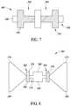
- FIG. 7is an alternative embodiment of the present disclosure having an enlarged heater with a plurality of heater openings
- FIG. 8is an alternative embodiment of the present disclosure having an enlarged heater with a plurality of heater openings
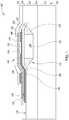
- FIG. 9is a cross-sectional view of an alternative embodiment of a gas sensor of the present disclosure that includes a passive hotplate between a heater and an active sensor area;
- FIG. 10is a cross-sectional view of a heater having multiple openings and a passive hotplate according to another embodiment of the present disclosure
- FIGS. 11 and 12are top and cross-sectional views of a gas sensor according to embodiments of the present disclosure.
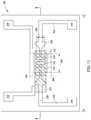
- FIGS. 13 and 14are views of a gas sensor according to another embodiment of the present disclosure.
- references throughout the specification to integrated circuitsis generally intended to include integrated circuit components built on semiconducting or glass substrates, whether or not the components are coupled together into a circuit or able to be interconnected.
- layeris used in its broadest sense to include a thin film, a cap, or the like and one layer may be composed of multiple sub-layers.
- the present disclosureis directed to various gas sensors that can be carried by a user, such as worn on their clothing, included within an electronic device, attached to a workstation, or incorporated in a room. These gas sensors will detect various species of gases that may be of interest to the user and provide information to the user regarding air quality associated with the user's current environment.
- the gas sensorscould be attached to a user's laptop or computer in an office setting.
- the gas sensorcan display air quality data on displays of the user's electronic devices, such as a tablet, monitor, or mobile telephone. The data may take the form of a statistical summary or a trench chart.
- the gas sensormay be incorporated in a package with a microprocessor, memory, and other sensors. The package may be directly coupled to the user's electronic device or may be plugged in to an existing port of the electronic device to transmit data from the gas sensor and related circuitry to the display.
- gas sensorsinclude a plurality of improvements that may be incorporated into gas sensors individually or as combinations.
- the improvementsinclude an enlarged heater, described in at least FIGS. 1-3 , a passive hot plate, described in at least FIGS. 9-10 , and a composite heater, described in at least FIGS. 4-7 .
- Each embodimentwill be described below and various combinations of these features will be described, however other combinations of these features are envisioned and may be selected based on operation of the particular application of the gas sensor.
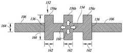
- FIG. 1is directed to a gas sensor 100 according to one embodiment of the present disclosure, which includes an enlarged heater 102 that corresponds to an active sensor area 104 .
- Good sensitivity of the gas sensoris achieved with a large heater area of the heater 102 , a large active sensor area, a high resistance through a heater interconnect 106 , and low power.
- the active sensor areais where a chemical reaction occurs with elements from an environment.
- the sensitivityis directly linked to a size of the active sensor area.
- the areamust be heated, which is achieved by power dissipation through a resistance in the heater interconnect using the Joule effect.
- the power consumptiondepends on the resistance and gives rise to a compromise between having a larger surface area and a small resistance to reduce the power demand.
- the enlarged heater 102allows for a larger surface for the chemical reaction while maintaining a same resistance (which determines the power consumption). This allows for existing application specific integrated circuits (ASICs) to be used with the design of this gas sensor 100 .
- ASICsapplication specific integrated circuits
- the heater 102is formed above a chamber 108 that is formed in a substrate 110 .
- the substrate 110may include a silicon layer 112 covered by a first dielectric layer 114 .
- the silicon layer 112may be 500-600 nanometers.
- the substrate 110may be glass.
- the first dielectric layermay be an oxide that is in the range of 3 microns and 10 microns; it may be deposited or grown.
- the chamber 108is formed as a recess 116 in the oxide layer 114 in this embodiment, such as with a photolithography process and an etch.
- the etchmay be a hydrogen fluoride etch that forms the recess having angled walls 118 and a bottom 120 having a 2 micron depth. Other dimensions are envisioned for this embodiment and all other embodiments of this application.
- the recess 116is filled with a polyimide 122 that is covered with a second dielectric layer 124 .
- the polyimide 122fills the recess and extends past the angled walls 118 to cover a portion 126 of a surface 128 of the first dielectric layer 114 .
- the second dielectricmay be a silicon nitride having a thickness in the range of 450 and 550 nanometers.
- the heater 102is formed on the second dielectric layer 124 and may include two layers.
- a first heater layer 130is formed on the second dielectric layer 124 and a second heater layer 132 is formed on the first heater layer 130 .
- the first heater layermay be a tantalum aluminum layer having a thickness of around 150 nanometers and the second heater layer may be an aluminum copper layer having a thickness of around 500 nanometers. Tantalum aluminum has a low thermal coefficient that results in a stable resistance.
- the second heater layer 132includes an opening 136 .
- a third dielectric layer 138is formed on the second heater layer 132 and in the opening 136 .
- the openingcorresponds to an enlarged heater area, which is described in more detail with respect to FIGS. 2-3 , among others.
- the heater 102having a thickness in the range of 500 and 600 nanometers away from the enlarged heater area and a thickness in the range of 100 and 200 nanometers in the enlarged heater area.
- the third dielectric layer 138may be a silicon nitride layer that is around 300 nanometers thick.
- An active sensor layer 140is formed on the third dielectric layer 138 .
- This active sensor layer 140may be a tin oxide that is approximately 100 nanometers thick.
- This type of layermay be referred to as a semiconductor metal oxide, SMO.
- SMOsemiconductor metal oxide
- a conductive layer 146couples the active sensor layer 140 to the heater 102 through a conductive via 148 through the third dielectric layer 138 .
- a liner 150may be formed between the conductive layer 146 and the active sensor layer 140 .
- the liner 150may be titanium tungsten at a thickness of 25 nanometers with the conductive layer 146 being an aluminum copper layer at a thickness of 500 nanometers.
- the chamber 108is formed by etching through the second, third, and fourth dielectric layers in a view now shown in FIG. 1 .
- the polyimide 122is then etched to form the chamber 108 .
- FIGS. 2-3are top down views of the enlarged heater area.
- FIG. 2includes the heater interconnect 106 , which is a dual layer of the first and second heater layers.
- the enlarged heater area 152corresponds to the opening 136 .
- the heater 102includes a main extension 154 and a plurality of secondary extensions 156 a - 156 c .
- Each secondary extension 156 a - 156 chas a same dimension 162 .
- a dimension 164 of the heater interconnect 106is smaller than a dimension 166 of the secondary extensions.
- Each of the secondary extensionsallows for thermal expansion of the heater.
- a total resistance of the heater 102is ideally in the range of 100 and 150 ohms in order to match demands of an associated ASIC.
- These secondary extensionsare not active from an electrical point of view and as such, no increase in power is used as compared to the main extension alone.
- the heat generated by the main extensionmoves outwardly towards the secondary extensions, as shown by arrows 160 . This allows for better heat uniformity in the heater area, which corresponds to better and larger heat uniformity in the active sensor area 104 .
- the larger the heated active sensor areathe more sensitive the gas sensor can be.
- a comparison of the main extension only and the main extension plus the secondary extensionis as follows where the resistance is the same (100 ohms) with a one milliamp current.
- the main extension alonehas a heater area of 576 micrometers squared where the main extension plus the secondary extensions has a heater area of 1728 micrometers squared.
- An area of the active sensor area for the main extension aloneis 192 micrometers and an area for the active sensor area of the main extension and the secondary extensions is 1700 micrometers squared.
- a ratio of the active sensor area to the heater area of the main extension aloneis 33% while a ratio of the active sensor area to the heater area of the main extension plus the secondary extensions is 98%. This results in a significant increase in sensitivity.
- FIG. 3is an alternative embodiment of the enlarged heater area 152 having the heater interconnects 106 with a different shape than those in FIG. 2 .
- the opening 136corresponds to the enlarged heater area 152 , which is only the first heater layer.
- the heaterincludes a first central extension 170 , a second and third extension 172 , 174 of the same dimensions as each other (dimension 178 ), and a fourth extension 176 that has different dimensions (dimension 180 ) than the second and third extensions.
- the fourth extension 176is illustrated as a square shape.
- the fourth extensioncan be any suitable shape.
- the fourth extensionis larger than the second extension in an area that the extension covers.
- FIG. 4is a cross-sectional view of a gas sensor 200 having multiple heater openings 202 and 204 according to an embodiment of the present disclosure. Two openings will be described; however, embodiments with three or more openings are envisioned. Features of the gas sensor 100 that are similar are referenced using the same reference numbers.
- the chamber 108is formed in the polyimide layer 122 , which is supported by the substrate 110 .
- sensitivity of such micro-electromechanical gas sensorsdepends on a size of an active sensor area 206 of an active sensor layer 208 .
- the active sensor area 206is a portion of the active sensor layer 208 that is exposed through an opening 210 in an upper dielectric layer 212 .
- the active sensor areais heated by a heater 214 to a temperature that may be in the range of 200 and 500 degrees Celsius. The heat needs to remain localized as to not damage other portions of the gas sensor or other sensors and components included with the gas sensor.
- the heateris heated by power dissipation through resistance and the Joule effect. Power consumption depends on the resistance of the heater. A lower resistance is preferred to maintain low power.
- the heateris a first conductive layer 216 and a second conductive layer 218 .
- the first layer 216is a tantalum aluminum layer, which allows for power dissipation through resistance while keeping the thermal dissipation stable.
- the second conductive layeris preferably an aluminum copper layer. Voltage is applied to the heater, power dissipation according to the joule effect starts at room temperature, the joule effect starts increasing the temperature of the heater, the heater resistance tends to increase as the temp increases, and the joule effect is modified due to the resistance change.
- openings 202 and 204are formed in the second conductive layer 218 . These openings create a succession of resistances in the heater 214 , which heat the active sensor area.
- the openings 202 and 204are within bounds of the opening 210 , i.e., from a top down view an entire area of the heater is within a boundary of the active sensor area.
- the first conductive layer 216is formed on the dielectric layer 124 , which is on the polyimide 122 .
- the second conductive layer 218is formed directly on the first conductive layer 216 .
- Each of the first and second conductive layersis a consistent thickness throughout in some embodiments.
- a dielectric layer 220is formed over the second conductive layer 218 .
- a first end 222 of the heater 214is coupled to a contact 226 that receives a voltage and a second end 224 of the heater 214 is coupled to ground.
- the contact 226is coupled to the active sensor layer 208 as well.
- Heatis generated at the openings 202 and 204 as the openings increase the resistance.
- the openings 202 and 204are micron by microns in area, for example 100 by 200 microns square. These openings make the heater more uniform across the active sensor area. There may be three, five, or more of these openings.
- FIG. 5is a top down view of a linear version of the heater 214 , which includes the first and second openings 202 , 204 .
- the heater 214has five sections 230 , 232 , 234 , 236 , 238 .
- the first section 230is a dual layer of the heater that includes the first and second conductive layers.
- the third and fifth sections 234 and 238are also the dual layer.
- the second and fourth sections 232 and 236correspond to the openings 214 , 216 , which have only one layer, the first conductive layer.
- the first layeris tantalum aluminum and the second layer is aluminum copper.
- the openingsexpose the first conductive layer 216 .
- the openingsmay form vertical sidewalls or may form angled sidewalls.
- the total resistance of the heateris preferably in the range of 100 and 150 ohms.
- the resistanceis 13.5 ohms/square and the second conductive layer is aluminum copper is 0.025 ohms/square.
- These openingsform two serial resistances under a same current and thus, the same power.
- the second conductive layerallows the heat to pass through the heater and have a better uniformity. This separates heating locations to cover a larger area of the active sensor layer.
- the second conductive layerhas higher thermal expansion than the first conductive layer, which conducts heat along the heater.
- the total resistance of the heaterdefines the power dissipation as well as the power consumption.
- a comparison of a device having only a single heater layer with the device 200 that includes openings in the second conductive layer on the first conductive layerare as follows.
- a resistance of the single heater deviceis 100 ohms with a current of one milliamp.
- the device 200 at a current of one milliampwill have a resistance of 55 ohms.
- the heater areais 576 microns squared.
- the heateris a single layer.
- the first conductive layeris 240 microns squared and the second conductive layer is 336 microns squared.
- the active sensor areais 192 microns squared and in the device 200 the active sensor area is 576 microns squared.
- the device 200includes a ratio of 100% of the heater area to the active sensor area.
- FIG. 6is an alternative embodiment of the present disclosure that includes a gas sensor 300 having a single heater structure 302 and a plurality of active sensor areas 308 , 310 , 312 .
- the heater structure 302includes at least two layers, a first conductive layer 304 that is covered by a second conductive layer 306 .
- the first conductive layeris exposed by openings 314 , 316 , 318 in the second conductive layer 306 .
- Each active sensor areaoverlaps the exposed portions of the first conductive layer through the openings 314 , 316 , 318 .
- a first end 320 of each active sensor areais coupled to a first terminal.
- a second end 322 of each active sensor areais coupled to ground.
- This plurality of active sensor areasmay each include an enlarged heater, such as those described in FIGS. 2 and 3 above. Other heater shapes and layer arrangements are described in more detail below and can be incorporated in this gas sensor 300 .
- Each of the active sensor areas 308 , 310 , 312may have a different resistance, which can have power dissipation proportional to the resistance.
- Each active sensor areacan operate at a different specific temperature, with a same power source. Different gases can be detected based on the different operating temperatures.
- FIG. 7is an alternative embodiment of the present disclosure having an enlarged heater 340 with a plurality of openings 342 , 344 .
- This heater 340includes two layers, a first conductive layer 346 that is formed first and a second conductive layer 348 that is formed on the first conductive layer.
- the heaterhas a main extension 350 and secondary extensions 352 that add surface area of the heater.
- FIG. 8is an alternative embodiment of the present disclosure having a heater 360 having a plurality of extensions and a plurality of openings 362 , 344 in one of the heater's layers.
- This heater 360includes two layers, a first conductive layer 366 that is formed first and a second conductive layer 368 that is formed on the first conductive layer.
- the heaterincludes a first terminal end 370 and a second terminal end 372 , which each have narrow to couple to a central portion 374 of the heater.
- First and second extensions 376 , 378that are similar to each other in size and shape overlap and extend from the central portion.
- a third extension 380overlaps and extends from the central portion 374 .
- the third extensionis square in shape and has a larger area than each of the individual first and second extensions 376 , 378 .
- the openingsare formed in conjunction with the first and second extensions. Openings may be formed in different locations or with different shapes as dictated by the gas sensor operating conditions or design choices.
- the active sensor layer in the embodiments described in this disclosureincludes a chemical reaction surface that is in contact with an external environment. High sensitivity of this chemical reaction surface corresponds to a large active area and a high concentration. This chemical reaction surface can detect different gas species based on the temperature at which it is operated. In addition, a concentration of the gas species may vary based on the use of the gas sensor. For example, a maximum of 3 parts per million of ethanol is acceptable in an office environment, which is within a range of 0.1 and 10 parts per million for the office environment. This range is compared to ethanol for a breathalyzer, which may be in the range of 5 and 1,000 parts per million.
- the active sensor layeris a thin film gas sensing material that has a structure that supports surface conduction of ambient gas along a substantially straight path.
- the active sensor layersupports a surface reaction between the ambient gas and a dense, multi-crystalline thin film that is made of a thin film gas sensing material.
- the thin filmis a tin oxide (SnO 2 ) film of thickness 100 nm.
- Other gas sensing materials that can be used as the thin filminclude zinc oxide (ZnO 2 ) and indium oxide (In 2 O 3 ).
- the thin filmmay be formed by sputter deposition, followed by sintering at a low temperature of 400 C. The resulting thin film is so dense that it is similar to a ceramic. Part or all of the thin film may then be capped with a thin coating of platinum (Pt).
- Ptplatinum
- the gas sensors of the present disclosuremay include a temperature sensor in conjunction with the heater and the active sensor area.
- the temperature sensormay be formed on a same substrate as the active sensor area.
- the resistive heateris electronically controlled by a microprocessor according to programmed instructions that may be in a separate package, in a same package or on a same or different substrate than the active sensor area.
- the microprocessorcan to tune the gas sensor to be sensitive to a particular gas.
- the temperature sensorcan be used as a feedback control device for automatically adjusting the resistive heater for a specific gas.
- each gas sensoris determined by the voltage V h and a resistance R H of an associated resistive heater 154 .
- the gas sensormay include multiple active sensor areas that are operated within a different temperature range, such that each of the resistances R H has different values. This can be accomplished by using different sensing materials in the active sensor areas.
- a first elementmay include SnO 2 and may be operated within a temperature range of 400 C-500 C
- a second element 150 bmay include ZnO 2 and may be operated in a temperature range of 300 C-350 C.
- each temperature sensoris configured as a Wheatstone bridge.
- VOC sensorscan be detected by VOC sensors based on material and operating temperature. For example, when a VOC sensor made of SnO 2 is heated to an operating temperature of 100 C, it is capable of detecting hydrogen gas. When the SnO 2 sensor is heated to an operating temperature of 300 C, it will detect carbon monoxide (CO), and at 400 C, it will detect methane. When a VOC sensor made of ZnO 2 is heated to 300 C, it detects nitrogen oxide (NO 2 ). When a VOC sensor made of InO 2 is heated to 300 C, it will detect Sulphur dioxide (SO 2 ). Other sensor materials can be substituted for, or used in addition to, SnO 2 , ZnO 2 , and InO 2 in the VOC sensors.
- the same physical materialis heated to different temperatures at different times to sense different gases.
- the SnO 2 layeris heated to about 200 C to detect butane and propane.
- the very same materialis heated to about 300 C to detect CO.
- the local temperature sensor adjacent to the materialprovides a feedback signal to ensure that the SnO 2 material is at the desired temperature for sensing the selected gas.
- FIG. 9is an alternative embodiment of a gas sensor 400 that includes a passive hotplate 402 aligned with a heater 404 .
- the gas sensoris formed on a substrate 406 that includes a sacrificial material 408 .
- the substratemay include a dielectric layer 410 in which a recess 412 is formed that supports the sacrificial material 408 .
- the sacrificial materialmay be polyimide of which some may remain in a final version of the gas sensor.
- a dielectric layer 414is formed on the sacrificial material 408 and supports the heater 404 .
- the heateris illustrated as a single layer; however, there may be additional layers.
- Another dielectric layer 416is formed on the heater.
- the passive hotplate 402is formed on this dielectric layer 416 .
- the passive hotplateis not electrically coupled to any other components, but is thermally coupled to the heater and to an active sensor area 418 .
- An active sensor layer 420includes the active sensor area 418 , which is exposed by an opening 422 through a dielectric layer 424 .
- the active sensor layer 420is electrically coupled to the heater 404 with a conductive via 428 .
- a chamber 430is formed in the sacrificial material 408 through openings (not shown in this view) from a top surface 432 of the sensor 400 .
- a single active sensor areacan detect different gases at different operating temperatures.
- Different gassescorrespond to different working temperature ranges and peak within their working temperature ranges. Some of the ranges overlap; however, the different peaks (maximum detection temperatures) are different temperatures.
- Selectivity of the gas sensorcan be improved by allowing the sensor to make several measurements at several operating temperatures.
- the working temperature range of the gas sensormust be less than a difference between the maximum detection temperatures between two gas species. The more precise the working temperature, the more precise the maximum detection will be. Selectivity between species is directly linked to the thermal homogeneity of the active sensor area.
- the passive hotplate 402increases the thermal uniformity of the active sensor area.
- the passive hotplate 402is a conductive layer, such as titanium tungsten.
- a dielectric layer 434separates the passive hotplate 402 from the active sensor layer 420 . This dielectric layer 434 may be silicon nitride.
- FIG. 10is an alternative embodiment of a passive hotplate 450 that is formed over a heater 452 having a first conductive layer 454 and a second conductive layer 456 . Openings 458 and 460 are formed in the second conductive layer 456 , which increase the thermal conductivity of the heater. There may be a single opening or two or more openings.
- a dielectric layer 462separates the heater from the passive hotplate.
- Another dielectric layer 464separates the passive hotplate from an active sensor layer 468 .
- a material for these passive hotplate layers described in this disclosureare selected based on thermal conductivity. Titanium tungsten has good thermal conductivity and accumulates heat to uniformly transfer it to the active sensor layer. In addition, titanium tungsten has low thermal expansion as compared to other allows and is not subjected to mechanical stresses. The passive hotplate more uniformly distributes heat as compared to a heater that has a smaller surface area than the active sensor area. Such a gas sensor includes two heating approaches that work together. An electro-thermal heat is generated in the heater then thermal conductivity heats the passive hotplate, which transfers the heater more uniformly to the sensor area. The hotplate has a greater surface area than the heater. A surface area of the active sensor area is greater than the heater area and less than or equal to the hotplate surface area.
- Comparing a single heater design with a heater and hotplate designresults in the following when using a 100 ohm resistor, current of seven milliamps, and a power of 4.9 milli watts, where the heater area for both designs is 576 microns squared.
- a usable area of the active sensor areais 192 microns squared for a single heater design as compared to a usable area of the active sensor area of 768 microns squared for the hotplate design.
- a ratio of the heater area to the suable areais 133% for the hotplate design.
- FIGS. 11 and 12are top and cross-sectional views of a gas sensor 500 that includes a combination of features, such as a two layer heater 502 , a passive hotplate 508 , and openings 514 , 516 , 518 in the two layer heater.
- the gas sensoris formed on a substrate 530 that includes an oxide 532 on the substrate.
- a recess in which polyimide 534 and a chamber 512 are formedis formed in the oxide layer.
- a dielectric layer 536is formed over the chamber, the polyimide, and the oxide.
- the heaterincludes a first layer 504 and a second layer 506 .
- the openingsare formed in the second layer 506 of the heater 502 .
- Another dielectric layer 538is formed on the heater and in the openings.
- the passive hotplateis formed on the dielectric layer 538 aligned with and overlapping the openings, as can be seen in FIG. 11 .
- a surface area of the hotplateis larger than a surface area of an active portion 540 of the heater 502 .
- the heaterincludes heater interconnects 542 that are coupled to contact 544 , 546 .
- a total area of the diemay be 0.4 mm by 0.4 mm.
- An active sensor layer 510is formed on the passive hotplate 508 and includes an active sensor area 550 on which the gas reacts to detect a species of gas. Detection signals are provided by contacts 552 , 554 to and from the active sensor area 550 .
- the active sensor layer 510is coupled to the heater 502 through via 520 .
- the heaterincludes triangular sections 560 to increase resistance; however, these are optional based on operational demands of the gas sensor.
- FIGS. 13 and 14are views of a gas sensor that includes a first heater layer 606 , a second heater layer 607 , a passive hotplate 605 , and an active sensor area 627 .
- the first heater layer 606is formed on a substrate 602 , which may be a semiconductor material, a glass substrate, or other suitable substrate.
- the second heater layer 607is formed on top of the first heater layer 606 .
- the second heater layermay be directly on top of and in contact with the first heater layer.
- the first heater layer 606is formed as a serpentine shape with curved ends 610 and straight portions 611 . This embodiment includes four curved ends on one side and three curved ends on the other. The curved ends are coupled to ones of the straight portions.
- the first heater layerincludes a first contact 612 and a second contact 614 .
- the first heater layer 606includes an enlarged heater area in a central portion that includes extensions 620 .
- the extensionshave dimensions that extend transverse to two centrally located straight portions.
- a first straight portion 613includes three extensions extending from one side and two extensions extending from the other side.
- a second straight portion 615includes a single extension extending from one side towards the first straight portion and three extensions extending from the other side. Different combinations of extensions are available depending on the operational constraints of the end product.
- the second heater layer 607has the same serpentine shape with curved ends 608 and straight portions 617 .
- Two centrally located straight portionsinclude a plurality of openings 622 , which cause the heat to be intensified when the first heater layer is activated, in accordance with different embodiments described above.
- the second heater layerincludes contacts 619 , 621 that overlap the contacts for the first heater layer. Power is transmitted through both the first and the second heater layer at the same time. In FIG. 13 , the combination of the first and second heater layers is shown in black and labeled 601 .
- the passive hotplate layer 605is formed above the extensions 620 and the openings 622 .
- the passive hotplate layerincludes openings 624 between overlapping portions 604 , 626 .
- a surface area covered by the passive hotplate layeris larger than an area of the extensions of the first and second heater layers.
- the passive hotplate layeris not electrically coupled to any other features. Instead, the passive hotplate layer is thermally coupled to the first and second heater layers.
- the active sensor area 627is part of an active sensor layer 605 (shown in stippling in FIG. 13 ).
- the active sensor layer 605includes contacts 616 , 618 at ends that are positioned on an opposite side of the substrate 602 from the contacts 612 , 614 for the first and second heater layers.
- the active sensor area 627is illustrated without stippling in FIG. 13 to illustrate the active sensor area 627 as compared to the active sensor layer. This active sensor area is exposed to an environment such that the gas species interact with this area for detection by the gas sensor.
- Openings 603are positioned between the serpentine layers to allow for removal of a sacrificial material that supports the layers until the chamber is formed.
- the gas sensorscan be included in a shared package with humidity and temperature sensors that assist to provide accurate gas readings. All processes used to form these sensors are thin film processes at less than 400 degrees Celsius. These are integrated multi-species gas micro-sensors that are smaller, more accurate, and less expensive than existing air quality sensors.
- the multi-species gas micro-sensorincludes a VOC sensor that includes a conformal thin film less than 0.2 micron thick.
- Each of the multi-species gas micro-sensoralso includes a heater having a low temperature coefficient of resistance.
- the present disclosureis directed to a device that includes a substrate, a heater formed on the substrate, the heater having: a first main portion extending in a first direction and a plurality of second portions extending from the first main portion in a second direction that is transverse to the first direction.
- the deviceincludes an active sensor area above the heater. The heater and the active sensor area are electrically and thermally coupled together.
- the deviceincludes a first dielectric layer on the substrate, the heater on the first dielectric layer, a second dielectric layer on the heater, an active sensor layer, and a third dielectric layer on the active sensor layer, the third dielectric layer including an opening that exposes the active sensor area of the active sensor layer.
- the plurality of second portionsincludes a first extension having a first area and a second extension having a second area. The first area is greater than the second area. Alternatively, the first area is substantially the same area as the second area.
- the substrateincludes a chamber formed between the substrate and the first dielectric layer, the heater being aligned over the chamber.
- the heaterincludes a first layer and a second layer, the first layer including an opening and the first main portion and the plurality of second portions being formed by the second layer. An area of the opening in the first layer encompasses boundaries of the first main portion and the plurality of second portions.
- the present disclosureis also directed to a device that includes a substrate, a heater on the substrate, the heater including a first conductive layer and a second conductive layer on the first conductive layer, the second conductive layer including a first opening and a second opening.
- the deviceincludes a first active sensor layer on the heater and a first dielectric layer on the first active sensor layer, the first dielectric layer including a third opening that exposes a first active sensor area of the active sensor layer.
- the active sensor areais aligned with and positioned over the first and second openings in the second conductive layer.
- the active sensor layeris coupled to the heater.
- a first end of the first active sensor layer and a first end of the second active sensor layerare coupled together and a second end of the first active sensor layer is coupled to a first terminal and a second end of the second active sensor layer is coupled to a second terminal.
- the first and second terminalsare controlled separately.
- the present disclosureis also directed to a device that includes a substrate, a heater on the substrate, a passive heat conductive plate on the heater, an active sensor layer on the passive heat conductive plate, and a first dielectric layer on the active sensor layer, the first dielectric layer including a first opening that exposes an active sensor area.
- the heaterincludes a first conductive layer on the substrate and a second conductive layer on the first conductive layer, the second conductive layer including a plurality of second openings that expose a surface of the first conductive layer.
- the deviceincludes a chamber in the substrate, the chamber being aligned with the active sensor area.
- the heaterincludes a first end, a second end, and a central region, the first and second ends having a first dimension in a first direction, the central region including a plurality of extensions having a second dimension in the first direction, the second dimension being larger than the first dimension.
- the first conductive layerincludes a first terminal, a second terminal, and a central region that extends between the first terminal and the second terminal and has a serpentine shape.
- the serpentine shapeincludes a plurality of linear portions coupled together by curved ends. Ones of the plurality of linear portions include protrusions that extend transversely from the linear portions.
- a first linear portionis adjacent to a second linear portion, the first linear portion including a plurality of first protrusions and a second linear portion including a plurality of second protrusions.
- a first linear portionincludes first protrusions on a first side of the first linear portion and a second linear portion includes second protrusions on a first side of the second linear portion that faces the first side of the first linear portion.
- the first protrusionsextend toward the second linear portion and the second protrusions extend toward the first protrusion.
- Ones of the first protrusionsare spaced from each other by one of the second protrusions.
- the first linear portionincludes third protrusions that extend from a second side of the first linear portion and the second linear portion includes fourth protrusions that extend from a second side of the second linear portion.
- the second conductive layerincludes a first terminal, a second terminal, and a central region that extends between the first terminal and the second terminal and has a serpentine shape.
- the first conductive layerincludes a plurality of protrusions in the central region.
- the second conductive layerincludes the plurality of second openings in the central region. The second openings are aligned with the plurality of protrusions.
- the passive heat conductive plateincludes a plurality of third openings.
- the passive heat conductive plateincludes a first and a section linear portion that are adjacent to each other and extend along a first direction and a third and fourth linear portion that are adjacent to each other and extend along a second direction that is transverse to the first direction.
- the active sensor layerincludes a plurality of third openings in the active sensor area.
- the deviceincludes the heater that includes a plurality of extensions, the passive heat conductive plate includes a plurality of second openings, the active sensor layer includes a plurality of third openings in the active sensor area.
- the plurality of extensionsare aligned with the first opening, the plurality of second openings, and the plurality of third openings.
- the substrateincludes a chamber, the plurality of extensions positioned over the chamber.
- the present disclosureincludes a method that includes forming a heater on a substrate by: forming a first conductive layer on the substrate, forming a second conductive layer on the first conductive layer, forming an active sensor layer on the heater, forming a first dielectric layer on the active sensor layer.
- the methodincludes forming an active sensor area by: forming a first opening in the first dielectric layer and reexposing a surface of the active sensor layer.
- the methodincludes forming a passive heat conductive hotplate between the heater and the active sensor area of the active sensor layer.
- the methodincludes forming a plurality of extensions in the heater, the plurality of extensions aligned with the first opening in the dielectric layer.
- the methodincludes forming a plurality of second openings in the second conductive layer.
- the methodincludes forming a recess in the substrate, forming a second dielectric in the recess in the substrate, forming the heater on the second dielectric in the recess, and forming a chamber by removing a first portion of the second dielectric in the recess.
- the methodincludes forming the recess including removing a portion of the substrate from a first surface of the substrate and forming the second dielectric layer includes forming the second dielectric layer in the recess and above the first surface of the substrate.
Landscapes
- Chemical & Material Sciences (AREA)
- Health & Medical Sciences (AREA)
- Life Sciences & Earth Sciences (AREA)
- Engineering & Computer Science (AREA)
- Immunology (AREA)
- Analytical Chemistry (AREA)
- Biochemistry (AREA)
- General Health & Medical Sciences (AREA)
- General Physics & Mathematics (AREA)
- Physics & Mathematics (AREA)
- Pathology (AREA)
- Combustion & Propulsion (AREA)
- Food Science & Technology (AREA)
- Medicinal Chemistry (AREA)
- Electrochemistry (AREA)
- Chemical Kinetics & Catalysis (AREA)
- Investigating Or Analyzing Materials By The Use Of Fluid Adsorption Or Reactions (AREA)
Abstract
Description
Claims (26)
Priority Applications (4)
| Application Number | Priority Date | Filing Date | Title |
|---|---|---|---|
| US15/367,081US10557812B2 (en) | 2016-12-01 | 2016-12-01 | Gas sensors |
| CN201720558907.9UCN207457118U (en) | 2016-12-01 | 2017-05-18 | For detecting the device of air quality |
| CN201710353023.4ACN108132330B (en) | 2016-12-01 | 2017-05-18 | Gas sensor |
| US16/709,811US11543378B2 (en) | 2016-12-01 | 2019-12-10 | Gas sensors |
Applications Claiming Priority (1)
| Application Number | Priority Date | Filing Date | Title |
|---|---|---|---|
| US15/367,081US10557812B2 (en) | 2016-12-01 | 2016-12-01 | Gas sensors |
Related Child Applications (1)
| Application Number | Title | Priority Date | Filing Date |
|---|---|---|---|
| US16/709,811ContinuationUS11543378B2 (en) | 2016-12-01 | 2019-12-10 | Gas sensors |
Publications (2)
| Publication Number | Publication Date |
|---|---|
| US20180156747A1 US20180156747A1 (en) | 2018-06-07 |
| US10557812B2true US10557812B2 (en) | 2020-02-11 |
Family
ID=62240490
Family Applications (2)
| Application Number | Title | Priority Date | Filing Date |
|---|---|---|---|
| US15/367,081ActiveUS10557812B2 (en) | 2016-12-01 | 2016-12-01 | Gas sensors |
| US16/709,811Active2037-12-25US11543378B2 (en) | 2016-12-01 | 2019-12-10 | Gas sensors |
Family Applications After (1)
| Application Number | Title | Priority Date | Filing Date |
|---|---|---|---|
| US16/709,811Active2037-12-25US11543378B2 (en) | 2016-12-01 | 2019-12-10 | Gas sensors |
Country Status (2)
| Country | Link |
|---|---|
| US (2) | US10557812B2 (en) |
| CN (2) | CN207457118U (en) |
Families Citing this family (5)
| Publication number | Priority date | Publication date | Assignee | Title |
|---|---|---|---|---|
| US10852233B2 (en) | 2016-06-15 | 2020-12-01 | Kidde Technologies, Inc. | Systems and methods for chamberless smoke detection and indoor air quality monitoring |
| US10871452B2 (en) | 2016-06-15 | 2020-12-22 | Kidde Technologies, Inc. | Systems and methods for chamberless smoke detection and indoor air quality monitoring |
| US11275043B2 (en)* | 2017-10-10 | 2022-03-15 | Indian Institute Of Science | Nano-sensor for detecting gaseous components |
| US10339778B1 (en)* | 2018-01-15 | 2019-07-02 | Kidde Technologies, Inc. | Chamberless air quality monitors with temperature sensing |
| CN116413314A (en)* | 2022-01-05 | 2023-07-11 | 财团法人工业技术研究院 | Micro-electromechanical sensing device and sensing module thereof |
Citations (109)
| Publication number | Priority date | Publication date | Assignee | Title |
|---|---|---|---|---|
| JPS58106451A (en) | 1981-12-18 | 1983-06-24 | Matsushita Electric Ind Co Ltd | gas detection element |
| US4608232A (en) | 1981-07-21 | 1986-08-26 | Hitachi, Ltd. | Gas sensor |
| US4938053A (en) | 1987-08-28 | 1990-07-03 | Thorm EMI Flow Measurement Limited | Fluid metering system |
| JPH04164242A (en) | 1990-10-29 | 1992-06-09 | Figaro Eng Inc | Gas detecting device and gas detecting method |
| US5834777A (en) | 1994-02-14 | 1998-11-10 | Telaire Systems, Inc. | NDIR gas sensor |
| US6111280A (en)* | 1997-01-15 | 2000-08-29 | University Of Warwick | Gas-sensing semiconductor devices |
| US6243474B1 (en) | 1996-04-18 | 2001-06-05 | California Institute Of Technology | Thin film electret microphone |
| US6322247B1 (en) | 1999-01-28 | 2001-11-27 | Honeywell International Inc. | Microsensor housing |
| US6352874B1 (en) | 1999-05-24 | 2002-03-05 | Motorola Inc. | Method of manufacturing a sensor |
| US6361206B1 (en) | 1999-01-28 | 2002-03-26 | Honeywell International Inc. | Microsensor housing |
| US6383832B1 (en) | 2001-04-16 | 2002-05-07 | Mitsubishi Denki Kabushiki Kaisha | Pressure responsive device and method of manufacturing semiconductor substrate for use in pressure responsive device |
| US20020160611A1 (en) | 2001-04-27 | 2002-10-31 | David Horsley | Method of fabricating suspended microstructures |
| US6478974B1 (en) | 1996-06-24 | 2002-11-12 | The Regents Of The University Of California | Microfabricated filter and shell constructed with a permeable membrane |
| US20020166376A1 (en) | 2001-05-08 | 2002-11-14 | Ngk Spark Plug Co., Ltd. | Split-flow flowmeter |
| US20030039299A1 (en) | 2001-07-16 | 2003-02-27 | Horovitz Michael L. | Sensor device and method for qualitative and quantitative analysis of gas phase substances |
| US6546812B2 (en) | 2001-05-11 | 2003-04-15 | Gary W. Lewis | Venturi flowmeter for use in an exhaust sampling apparatus |
| US20030079542A1 (en) | 2001-10-30 | 2003-05-01 | Ulrich Bonne | Flow and pressure sensor for harsh fluids |
| US6592823B1 (en)* | 1998-10-09 | 2003-07-15 | Basf Aktiengesellschaft | Sensor for detecting the instantaneous concentrations of a plurality of gas constituents in a gas |
| US20040008041A1 (en) | 2002-07-09 | 2004-01-15 | Davis Richard A. | Methods and systems for capacitive balancing of relative humidity sensors having integrated signal conditioning |
| US6698297B2 (en) | 2002-06-28 | 2004-03-02 | Weatherford/Lamb, Inc. | Venturi augmented flow meter |
| US20040084308A1 (en) | 2002-11-01 | 2004-05-06 | Cole Barrett E. | Gas sensor |
| US6879089B2 (en) | 2003-04-14 | 2005-04-12 | Agilent Technologies, Inc. | Damped longitudinal mode optical latching relay |
| US20050109081A1 (en) | 2003-11-21 | 2005-05-26 | Anis Zribi | Miniaturized multi-gas and vapor sensor devices and associated methods of fabrication |
| TW200531224A (en) | 2004-03-12 | 2005-09-16 | Advanced Systems Automation | Semiconductor package singulating system and method |
| US20050218465A1 (en) | 2004-04-02 | 2005-10-06 | Timothy Cummins | Integrated electronic sensor |
| CN1684285A (en) | 2004-04-16 | 2005-10-19 | 中国科学院电子学研究所 | Microstructure gas sensor array chip and preparation method thereof |
| US20060162466A1 (en) | 2002-07-19 | 2006-07-27 | Christopher Wargo | Fluid flow measuring and proportional fluid flow control device |
| US7280436B2 (en) | 2004-05-07 | 2007-10-09 | Corporation For National Research Initiatives | Miniature acoustic detector based on electron surface tunneling |
| US20080163687A1 (en) | 2004-10-15 | 2008-07-10 | Morgan Research Corporation | MEMS Sensor Suite on a Chip |
| US20080194053A1 (en) | 2005-05-18 | 2008-08-14 | Kolo Technologies, Inc. | Methods for Fabricating Micro-Electro-Mechanical Devices |
| US7437951B2 (en) | 2006-01-03 | 2008-10-21 | Freescale Semiconductor, Inc. | Method of using a differential pressure type flowmeter |
| US20080308920A1 (en) | 2002-08-07 | 2008-12-18 | Chang-Feng Wan | System and method of fabricating micro cavities |
| US20080315332A1 (en) | 2005-12-15 | 2008-12-25 | Arnd Kaelberer | Micromechanical Component and Manufacturing Method |
| US7556895B2 (en) | 2001-06-08 | 2009-07-07 | Sony Corporation | Mask, method of producing mask, and method of producing semiconductor device |
| US20090218702A1 (en) | 2005-06-08 | 2009-09-03 | Interuniversitair Microelektronica Centrum Vzw (Imec) | Methods for bonding and micro-electronic devices produced according to such methods |
| CN201307027Y (en) | 2008-10-23 | 2009-09-09 | 武汉恒翔微机电有限公司 | Thermal mass flowmeter |
| US20090243003A1 (en) | 2008-03-28 | 2009-10-01 | Stmicroelectronics S.R.L. | Manufacturing method of a gas sensor integrated on a semiconductor substrate |
| US7703339B2 (en) | 2005-12-09 | 2010-04-27 | Analog Devices, Inc. | Flow sensor chip |
| US20100173437A1 (en) | 2008-10-21 | 2010-07-08 | Wygant Ira O | Method of fabricating CMUTs that generate low-frequency and high-intensity ultrasound |
| CN101788315A (en) | 2010-02-05 | 2010-07-28 | 曲靖众一精细化工股份有限公司 | Method for precisely measuring wet gas |
| CN201589950U (en) | 2009-09-30 | 2010-09-22 | 江苏省农机具开发应用中心 | Livestock breeding environment monitor |
| US7821085B2 (en) | 2008-04-22 | 2010-10-26 | Denso Corporation | Physical quantity sensor and method for manufacturing the same |
| US20100314740A1 (en) | 2009-06-15 | 2010-12-16 | Samsung Electronics Co., Ltd. | Semiconductor package, stack module, card, and electronic system |
| US7864403B2 (en) | 2009-03-27 | 2011-01-04 | Qualcomm Mems Technologies, Inc. | Post-release adjustment of interferometric modulator reflectivity |
| US20110031565A1 (en) | 2009-08-04 | 2011-02-10 | David Lambe Marx | Micromachined devices and fabricating the same |
| CN101975751A (en) | 2010-10-13 | 2011-02-16 | 重庆大学 | Embedded type harmful gas detection system |
| US20110045639A1 (en) | 2007-12-04 | 2011-02-24 | Hitachi Chemical Company, Ltd. | Photosensitive adhesive |
| US20110108932A1 (en) | 2004-12-22 | 2011-05-12 | Hubert Benzel | Micromechanical Capacitive Sensor Element |
| US7946505B2 (en) | 2004-09-15 | 2011-05-24 | Magna Donnelly Engineering Gmbh | Environmental control system for a vehicle |
| US20110150261A1 (en) | 2009-12-17 | 2011-06-23 | Industrial Technology Research Institute | Capacitive transducer and fabrication method |
| US8062497B2 (en) | 2006-03-28 | 2011-11-22 | Imec | Method for forming a hermetically sealed cavity |
| US20110298134A1 (en) | 2009-04-03 | 2011-12-08 | Research Triangle Institute | Three dimensional interconnect structure and method thereof |
| US20120024054A1 (en) | 2010-07-30 | 2012-02-02 | Siargo Ltd. | High accuracy battery-operated mems mass flow meter |
| US20120032283A1 (en) | 2010-08-09 | 2012-02-09 | Jens Frey | Sensor module |
| US20120144921A1 (en) | 2010-12-10 | 2012-06-14 | Honeywell International Inc. | Increased sensor die adhesion |
| US20120167392A1 (en) | 2010-12-30 | 2012-07-05 | Stmicroelectronics Pte. Ltd. | Razor with chemical and biological sensor |
| CN102680018A (en) | 2011-03-09 | 2012-09-19 | 刘胜 | Multifunctional combined sensor |
| CN102680016A (en) | 2012-05-14 | 2012-09-19 | 北京理工大学 | Error compensating method of photoelectric encoder |
| CN102735716A (en) | 2011-04-08 | 2012-10-17 | Nxp股份有限公司 | Capacitive sensor, integrated circuit, electronic device and method |
| US8304850B2 (en)* | 2009-12-22 | 2012-11-06 | Texas Instruments Incorporated | Integrated infrared sensors with optical elements, and methods |
| US20120299127A1 (en) | 2011-05-27 | 2012-11-29 | Denso Corporation | Dynamic quantity sensor device and manufacturing method of the same |
| US20120304742A1 (en) | 2004-04-02 | 2012-12-06 | ChipSensors Limited | Integrated cmos porous sensor |
| US20130010826A1 (en) | 2011-07-05 | 2013-01-10 | Stmicroelectronics Pte Ltd. | Microsensor with integrated temperature control |
| CN102879648A (en) | 2012-10-07 | 2013-01-16 | 复旦大学 | Resistance change detection device for thin film resistive gas sensor |
| CN102915993A (en) | 2011-08-03 | 2013-02-06 | Nxp股份有限公司 | Integrated circuit with sensor and method of manufacturing such an integrated circuit |
| US20130036806A1 (en) | 2011-08-09 | 2013-02-14 | Denso Corporation | Air flow measuring device |
| US8390121B2 (en) | 2010-06-09 | 2013-03-05 | Mitsubishi Electric Corporation | Semiconductor device and method of manufacture thereof |
| CN202770456U (en) | 2012-08-21 | 2013-03-06 | 江苏物联网研究发展中心 | MEMS (Micro Electro Mechanical System) film capacitive type multi-parameter sensor structure |
| US20130106813A1 (en) | 2011-10-27 | 2013-05-02 | Steven P. Hotelling | Electronic Device with Chip-On-Glass Ambient Light Sensors |
| US20130139587A1 (en) | 2011-12-02 | 2013-06-06 | Stmicroelectronics Pte Ltd. | Tunable humidity sensor with integrated heater |
| US8487387B2 (en) | 2010-08-23 | 2013-07-16 | Freescale Semiconductor, Inc. | MEMS sensor device with multi-stimulus sensing |
| CN103226040A (en) | 2012-01-31 | 2013-07-31 | Nxp股份有限公司 | Integrated circuit and manufacturing method |
| US20130202489A1 (en) | 2012-02-03 | 2013-08-08 | The Hong Kong Polytechnic University | Gas sensor with a highly porous structure constructed of catalyst-capped metal-oxide nanoclusters |
| CN103364455A (en) | 2012-03-30 | 2013-10-23 | Nxp股份有限公司 | Integrated circuit comprising a gas sensor |
| US20130334620A1 (en) | 2012-06-15 | 2013-12-19 | Taiwan Semiconductor Manufacturing Company, Ltd. | MEMS Devices and Fabrication Methods Thereof |
| US20130344609A1 (en) | 2012-06-21 | 2013-12-26 | Felix Mayer | Chemical sensor in a portable electronic device |
| CN103528620A (en) | 2012-07-03 | 2014-01-22 | 黄正宇 | Multi-parameter sensing system integrated chip |
| US8696989B2 (en) | 2011-05-27 | 2014-04-15 | The Board Of Trustees Of The Leland Stanford Junior Univerity | Calorimeter sensor |
| CN103728350A (en) | 2012-10-12 | 2014-04-16 | Nxp股份有限公司 | Integrated Circuit comprising thermal conductivity based gas sensor |
| US8715514B2 (en) | 2008-12-22 | 2014-05-06 | Electronics And Telecommunications Research Institute | Micro-electromechanical systems (MEMS) microphone and method of manufacturing the same |
| US20140197500A1 (en) | 2013-01-11 | 2014-07-17 | MEAS France | Capacitive sensor integrated onto semiconductor circuit |
| US8806933B2 (en) | 2011-04-04 | 2014-08-19 | Denso Corporation | Thermal type air flow meter |
| US20140264655A1 (en) | 2013-03-13 | 2014-09-18 | Invensense, Inc. | Surface roughening to reduce adhesion in an integrated mems device |
| US20140264744A1 (en) | 2013-03-13 | 2014-09-18 | Taiwan Semiconductor Manufacturing Company, Ltd. | Stacked semiconductor device and method of forming the same |
| US20140268523A1 (en) | 2013-03-15 | 2014-09-18 | Bishnu Prasanna Gogoi | Wearable device having a monolithically integrated multi-sensor device on a semiconductor substrate and method therefor |
| US20140292317A1 (en) | 2013-03-29 | 2014-10-02 | Stmicroelectronics Pte Ltd. | Durable miniature gas composition detector having fast response time |
| US20140291677A1 (en) | 2013-03-29 | 2014-10-02 | Stmicroelectronics Pte Ltd. | Integrated multi-sensor module |
| US20140294046A1 (en) | 2013-03-29 | 2014-10-02 | Stmicroelectronics Pte Ltd. | Microelectronic environmental sensing module |
| US20140291829A1 (en) | 2013-03-29 | 2014-10-02 | Stmicroelectronics Pte Ltd. | Adhesive bonding technique for use with capacitive micro-sensors |
| US8852513B1 (en) | 2011-09-30 | 2014-10-07 | Silicon Laboratories Inc. | Systems and methods for packaging integrated circuit gas sensor systems |
| US20140311905A1 (en) | 2010-11-24 | 2014-10-23 | Kwj Engineering, Inc. | Printed Gas Sensor |
| US20140353773A1 (en) | 2013-05-31 | 2014-12-04 | STMicroelectronics Ptd Ltd. | Method for forming a suspended membrane |
| WO2015071337A1 (en) | 2013-11-12 | 2015-05-21 | Lfoundry S.R.L. | Integrated gas sensor and related manufacturing process |
| CN104792829A (en) | 2014-04-07 | 2015-07-22 | 英诺晶片科技股份有限公司 | Sensor device |
| US9105479B2 (en) | 2012-09-11 | 2015-08-11 | Ams International Ag | Integrated circuit including an environmental sensor |
| US9164052B1 (en)* | 2011-09-30 | 2015-10-20 | Silicon Laboratories Inc. | Integrated gas sensor |
| US20150323510A1 (en) | 2014-05-08 | 2015-11-12 | Active-Semi, Inc. | Olfactory Application Controller Integrated Circuit |
| US20160018356A1 (en) | 2014-07-17 | 2016-01-21 | Stmicroelectronics Pte Ltd | Integrated smo gas sensor module |
| US9317155B2 (en) | 2013-12-27 | 2016-04-19 | Intel Corporation | Ruggedized wearable electronic device for wireless communication |
| CN105510526A (en) | 2014-10-10 | 2016-04-20 | 意法半导体有限公司 | Gas sensor device with frame access and associated method |
| WO2016100210A1 (en) | 2014-12-15 | 2016-06-23 | Robert Bosch Gmbh | Nanolaminate gas sensor and method of fabricating a nanolaminate gas sensor using atomic layer deposition |
| CN105940295A (en) | 2013-12-06 | 2016-09-14 | 罗伯特·博世有限公司 | Semiconductor sensor having suspended structure and its manufacturing method |
| US9459224B1 (en)* | 2015-06-30 | 2016-10-04 | Taiwan Semiconductor Manufacturing Co., Ltd. | Gas sensor, integrated circuit device using the same, and manufacturing method thereof |
| CN106164661A (en) | 2014-03-05 | 2016-11-23 | 剑桥Cmos传感器有限公司 | Semiconductor equipment based on CMOS on micro-hotplate and manufacture method thereof |
| US20170016866A1 (en) | 2015-07-13 | 2017-01-19 | International Business Machines Corporation | Reconfigurable gas sensor architecture with a high sensitivity at low temperatures |
| US20170066646A1 (en) | 2015-09-03 | 2017-03-09 | Taiwan Semiconductor Manufacturing Company Ltd. | Semiconductor structure and manufacturing method thereof |
| US20170336343A1 (en) | 2016-05-19 | 2017-11-23 | InSyte Systems | Integrated sensing device for detecting gasses |
| US20180017513A1 (en) | 2016-07-18 | 2018-01-18 | Stmicroelectronics Pte Ltd | Miniature gas analyzer |
| US20180017536A1 (en) | 2016-07-18 | 2018-01-18 | Stmicroelectronics Pte Ltd | Integrated air quality sensor |
Family Cites Families (8)
| Publication number | Priority date | Publication date | Assignee | Title |
|---|---|---|---|---|
| US5302935A (en)* | 1992-12-08 | 1994-04-12 | Eastman Kodak Company | Renewable gas sensor, renewable gas sensor base and method for renewing a gas sensor |
| US5372785A (en)* | 1993-09-01 | 1994-12-13 | International Business Machines Corporation | Solid-state multi-stage gas detector |
| US6238085B1 (en)* | 1998-12-31 | 2001-05-29 | Honeywell International Inc. | Differential thermal analysis sensor |
| US6529686B2 (en)* | 2001-06-06 | 2003-03-04 | Fsi International, Inc. | Heating member for combination heating and chilling apparatus, and methods |
| EP2741322B1 (en)* | 2012-12-10 | 2016-04-27 | ams AG | Semiconductor device with integrated hot plate and recessed substrate and method of production |
| WO2016109430A1 (en)* | 2014-12-29 | 2016-07-07 | Robert Bosch Gmbh | Nanostructured gas sensor |
| EP3615926B1 (en)* | 2017-04-26 | 2024-09-18 | Nevada Nanotech Systems Inc. | Gas sensors including microhotplates with resistive heaters, and related methods |
| US10622316B2 (en)* | 2017-05-08 | 2020-04-14 | International Business Machines Corporation | Security arrangement for integrated circuits using microcapsules in dielectric layer |
- 2016
- 2016-12-01USUS15/367,081patent/US10557812B2/enactiveActive
- 2017
- 2017-05-18CNCN201720558907.9Upatent/CN207457118U/enactiveActive
- 2017-05-18CNCN201710353023.4Apatent/CN108132330B/enactiveActive
- 2019
- 2019-12-10USUS16/709,811patent/US11543378B2/enactiveActive
Patent Citations (128)
| Publication number | Priority date | Publication date | Assignee | Title |
|---|---|---|---|---|
| US4608232A (en) | 1981-07-21 | 1986-08-26 | Hitachi, Ltd. | Gas sensor |
| JPS58106451A (en) | 1981-12-18 | 1983-06-24 | Matsushita Electric Ind Co Ltd | gas detection element |
| US4938053A (en) | 1987-08-28 | 1990-07-03 | Thorm EMI Flow Measurement Limited | Fluid metering system |
| JPH04164242A (en) | 1990-10-29 | 1992-06-09 | Figaro Eng Inc | Gas detecting device and gas detecting method |
| US5834777A (en) | 1994-02-14 | 1998-11-10 | Telaire Systems, Inc. | NDIR gas sensor |
| US6243474B1 (en) | 1996-04-18 | 2001-06-05 | California Institute Of Technology | Thin film electret microphone |
| US6478974B1 (en) | 1996-06-24 | 2002-11-12 | The Regents Of The University Of California | Microfabricated filter and shell constructed with a permeable membrane |
| US6111280A (en)* | 1997-01-15 | 2000-08-29 | University Of Warwick | Gas-sensing semiconductor devices |
| US6592823B1 (en)* | 1998-10-09 | 2003-07-15 | Basf Aktiengesellschaft | Sensor for detecting the instantaneous concentrations of a plurality of gas constituents in a gas |
| US6322247B1 (en) | 1999-01-28 | 2001-11-27 | Honeywell International Inc. | Microsensor housing |
| US6361206B1 (en) | 1999-01-28 | 2002-03-26 | Honeywell International Inc. | Microsensor housing |
| US6352874B1 (en) | 1999-05-24 | 2002-03-05 | Motorola Inc. | Method of manufacturing a sensor |
| US6383832B1 (en) | 2001-04-16 | 2002-05-07 | Mitsubishi Denki Kabushiki Kaisha | Pressure responsive device and method of manufacturing semiconductor substrate for use in pressure responsive device |
| US20020160611A1 (en) | 2001-04-27 | 2002-10-31 | David Horsley | Method of fabricating suspended microstructures |
| US20020166376A1 (en) | 2001-05-08 | 2002-11-14 | Ngk Spark Plug Co., Ltd. | Split-flow flowmeter |
| US6546812B2 (en) | 2001-05-11 | 2003-04-15 | Gary W. Lewis | Venturi flowmeter for use in an exhaust sampling apparatus |
| US7556895B2 (en) | 2001-06-08 | 2009-07-07 | Sony Corporation | Mask, method of producing mask, and method of producing semiconductor device |
| US20030039299A1 (en) | 2001-07-16 | 2003-02-27 | Horovitz Michael L. | Sensor device and method for qualitative and quantitative analysis of gas phase substances |
| US20030079542A1 (en) | 2001-10-30 | 2003-05-01 | Ulrich Bonne | Flow and pressure sensor for harsh fluids |
| US6698297B2 (en) | 2002-06-28 | 2004-03-02 | Weatherford/Lamb, Inc. | Venturi augmented flow meter |
| US20040008041A1 (en) | 2002-07-09 | 2004-01-15 | Davis Richard A. | Methods and systems for capacitive balancing of relative humidity sensors having integrated signal conditioning |
| US20060162466A1 (en) | 2002-07-19 | 2006-07-27 | Christopher Wargo | Fluid flow measuring and proportional fluid flow control device |
| US20080308920A1 (en) | 2002-08-07 | 2008-12-18 | Chang-Feng Wan | System and method of fabricating micro cavities |
| CN1732383A (en) | 2002-11-01 | 2006-02-08 | 霍尼韦尔国际公司 | Gas sensor |
| US20040084308A1 (en) | 2002-11-01 | 2004-05-06 | Cole Barrett E. | Gas sensor |
| US6879089B2 (en) | 2003-04-14 | 2005-04-12 | Agilent Technologies, Inc. | Damped longitudinal mode optical latching relay |
| US20050109081A1 (en) | 2003-11-21 | 2005-05-26 | Anis Zribi | Miniaturized multi-gas and vapor sensor devices and associated methods of fabrication |
| WO2005087471A1 (en) | 2004-03-12 | 2005-09-22 | Advanced Systems Automation Limited | Semiconductor package singulating system and method |
| TW200531224A (en) | 2004-03-12 | 2005-09-16 | Advanced Systems Automation | Semiconductor package singulating system and method |
| CN1961209A (en) | 2004-04-02 | 2007-05-09 | 蒂莫西·卡明斯 | Integrated electronic sensor |
| US20120304742A1 (en) | 2004-04-02 | 2012-12-06 | ChipSensors Limited | Integrated cmos porous sensor |
| US20050218465A1 (en) | 2004-04-02 | 2005-10-06 | Timothy Cummins | Integrated electronic sensor |
| CN1684285A (en) | 2004-04-16 | 2005-10-19 | 中国科学院电子学研究所 | Microstructure gas sensor array chip and preparation method thereof |
| US7280436B2 (en) | 2004-05-07 | 2007-10-09 | Corporation For National Research Initiatives | Miniature acoustic detector based on electron surface tunneling |
| US7946505B2 (en) | 2004-09-15 | 2011-05-24 | Magna Donnelly Engineering Gmbh | Environmental control system for a vehicle |
| US20080163687A1 (en) | 2004-10-15 | 2008-07-10 | Morgan Research Corporation | MEMS Sensor Suite on a Chip |
| US20110108932A1 (en) | 2004-12-22 | 2011-05-12 | Hubert Benzel | Micromechanical Capacitive Sensor Element |
| US20080194053A1 (en) | 2005-05-18 | 2008-08-14 | Kolo Technologies, Inc. | Methods for Fabricating Micro-Electro-Mechanical Devices |
| US20090218702A1 (en) | 2005-06-08 | 2009-09-03 | Interuniversitair Microelektronica Centrum Vzw (Imec) | Methods for bonding and micro-electronic devices produced according to such methods |
| US7703339B2 (en) | 2005-12-09 | 2010-04-27 | Analog Devices, Inc. | Flow sensor chip |
| US20080315332A1 (en) | 2005-12-15 | 2008-12-25 | Arnd Kaelberer | Micromechanical Component and Manufacturing Method |
| US7437951B2 (en) | 2006-01-03 | 2008-10-21 | Freescale Semiconductor, Inc. | Method of using a differential pressure type flowmeter |
| US8062497B2 (en) | 2006-03-28 | 2011-11-22 | Imec | Method for forming a hermetically sealed cavity |
| US20110045639A1 (en) | 2007-12-04 | 2011-02-24 | Hitachi Chemical Company, Ltd. | Photosensitive adhesive |
| US20090243003A1 (en) | 2008-03-28 | 2009-10-01 | Stmicroelectronics S.R.L. | Manufacturing method of a gas sensor integrated on a semiconductor substrate |
| US7821085B2 (en) | 2008-04-22 | 2010-10-26 | Denso Corporation | Physical quantity sensor and method for manufacturing the same |
| US20100173437A1 (en) | 2008-10-21 | 2010-07-08 | Wygant Ira O | Method of fabricating CMUTs that generate low-frequency and high-intensity ultrasound |
| CN201307027Y (en) | 2008-10-23 | 2009-09-09 | 武汉恒翔微机电有限公司 | Thermal mass flowmeter |
| US8715514B2 (en) | 2008-12-22 | 2014-05-06 | Electronics And Telecommunications Research Institute | Micro-electromechanical systems (MEMS) microphone and method of manufacturing the same |
| US7864403B2 (en) | 2009-03-27 | 2011-01-04 | Qualcomm Mems Technologies, Inc. | Post-release adjustment of interferometric modulator reflectivity |
| US20110298134A1 (en) | 2009-04-03 | 2011-12-08 | Research Triangle Institute | Three dimensional interconnect structure and method thereof |
| US20100314740A1 (en) | 2009-06-15 | 2010-12-16 | Samsung Electronics Co., Ltd. | Semiconductor package, stack module, card, and electronic system |
| US20110031565A1 (en) | 2009-08-04 | 2011-02-10 | David Lambe Marx | Micromachined devices and fabricating the same |
| CN201589950U (en) | 2009-09-30 | 2010-09-22 | 江苏省农机具开发应用中心 | Livestock breeding environment monitor |
| US20110150261A1 (en) | 2009-12-17 | 2011-06-23 | Industrial Technology Research Institute | Capacitive transducer and fabrication method |
| US8304850B2 (en)* | 2009-12-22 | 2012-11-06 | Texas Instruments Incorporated | Integrated infrared sensors with optical elements, and methods |
| CN101788315A (en) | 2010-02-05 | 2010-07-28 | 曲靖众一精细化工股份有限公司 | Method for precisely measuring wet gas |
| CN101788315B (en) | 2010-02-05 | 2012-11-14 | 曲靖众一精细化工股份有限公司 | Method for precisely measuring wet gas |
| US8390121B2 (en) | 2010-06-09 | 2013-03-05 | Mitsubishi Electric Corporation | Semiconductor device and method of manufacture thereof |
| US20120024054A1 (en) | 2010-07-30 | 2012-02-02 | Siargo Ltd. | High accuracy battery-operated mems mass flow meter |
| US20120032283A1 (en) | 2010-08-09 | 2012-02-09 | Jens Frey | Sensor module |
| US8487387B2 (en) | 2010-08-23 | 2013-07-16 | Freescale Semiconductor, Inc. | MEMS sensor device with multi-stimulus sensing |
| CN101975751A (en) | 2010-10-13 | 2011-02-16 | 重庆大学 | Embedded type harmful gas detection system |
| US20140311905A1 (en) | 2010-11-24 | 2014-10-23 | Kwj Engineering, Inc. | Printed Gas Sensor |
| US20120144921A1 (en) | 2010-12-10 | 2012-06-14 | Honeywell International Inc. | Increased sensor die adhesion |
| US20120171713A1 (en) | 2010-12-30 | 2012-07-05 | Stmicroelectronics Pte Ltd. | Single chip having the chemical sensor and electronics on the same die |
| US20120171774A1 (en) | 2010-12-30 | 2012-07-05 | Stmicroelectronics Pte Ltd. | Chemical sensor with replaceable sample collection chip |
| US20120168882A1 (en) | 2010-12-30 | 2012-07-05 | Stmicroelectronics Pte Ltd. | Integrated chemical sensor |
| US20120167392A1 (en) | 2010-12-30 | 2012-07-05 | Stmicroelectronics Pte. Ltd. | Razor with chemical and biological sensor |
| CN102680018A (en) | 2011-03-09 | 2012-09-19 | 刘胜 | Multifunctional combined sensor |
| US8806933B2 (en) | 2011-04-04 | 2014-08-19 | Denso Corporation | Thermal type air flow meter |
| CN102735716A (en) | 2011-04-08 | 2012-10-17 | Nxp股份有限公司 | Capacitive sensor, integrated circuit, electronic device and method |
| US8779781B2 (en) | 2011-04-08 | 2014-07-15 | Nxp, B.V. | Capacitive sensor, integrated circuit, electronic device and method |
| US8696989B2 (en) | 2011-05-27 | 2014-04-15 | The Board Of Trustees Of The Leland Stanford Junior Univerity | Calorimeter sensor |
| US20120299127A1 (en) | 2011-05-27 | 2012-11-29 | Denso Corporation | Dynamic quantity sensor device and manufacturing method of the same |
| US20130010826A1 (en) | 2011-07-05 | 2013-01-10 | Stmicroelectronics Pte Ltd. | Microsensor with integrated temperature control |
| CN102915993A (en) | 2011-08-03 | 2013-02-06 | Nxp股份有限公司 | Integrated circuit with sensor and method of manufacturing such an integrated circuit |
| US8853798B2 (en) | 2011-08-03 | 2014-10-07 | Nxp, B.V. | Integrated circuit with sensor and method of manufacturing such an integrated circuit |
| US20130036806A1 (en) | 2011-08-09 | 2013-02-14 | Denso Corporation | Air flow measuring device |
| US9164052B1 (en)* | 2011-09-30 | 2015-10-20 | Silicon Laboratories Inc. | Integrated gas sensor |
| US8852513B1 (en) | 2011-09-30 | 2014-10-07 | Silicon Laboratories Inc. | Systems and methods for packaging integrated circuit gas sensor systems |
| US20130106813A1 (en) | 2011-10-27 | 2013-05-02 | Steven P. Hotelling | Electronic Device with Chip-On-Glass Ambient Light Sensors |
| US20130139587A1 (en) | 2011-12-02 | 2013-06-06 | Stmicroelectronics Pte Ltd. | Tunable humidity sensor with integrated heater |
| US8896073B2 (en) | 2012-01-31 | 2014-11-25 | Nxp B.V. | Integrated circuit and manufacturing method |
| CN103226040A (en) | 2012-01-31 | 2013-07-31 | Nxp股份有限公司 | Integrated circuit and manufacturing method |
| US20130202489A1 (en) | 2012-02-03 | 2013-08-08 | The Hong Kong Polytechnic University | Gas sensor with a highly porous structure constructed of catalyst-capped metal-oxide nanoclusters |
| US9263500B2 (en) | 2012-03-30 | 2016-02-16 | Ams International Ag | Integrated circuit comprising a gas sensor |
| CN103364455A (en) | 2012-03-30 | 2013-10-23 | Nxp股份有限公司 | Integrated circuit comprising a gas sensor |
| CN102680016A (en) | 2012-05-14 | 2012-09-19 | 北京理工大学 | Error compensating method of photoelectric encoder |
| US20130334620A1 (en) | 2012-06-15 | 2013-12-19 | Taiwan Semiconductor Manufacturing Company, Ltd. | MEMS Devices and Fabrication Methods Thereof |
| CN103512926A (en) | 2012-06-21 | 2014-01-15 | 森斯瑞股份公司 | Chemical sensor in a portable electronic device |
| US20130344609A1 (en) | 2012-06-21 | 2013-12-26 | Felix Mayer | Chemical sensor in a portable electronic device |
| CN103528620A (en) | 2012-07-03 | 2014-01-22 | 黄正宇 | Multi-parameter sensing system integrated chip |
| CN202770456U (en) | 2012-08-21 | 2013-03-06 | 江苏物联网研究发展中心 | MEMS (Micro Electro Mechanical System) film capacitive type multi-parameter sensor structure |
| US9105479B2 (en) | 2012-09-11 | 2015-08-11 | Ams International Ag | Integrated circuit including an environmental sensor |
| CN102879648A (en) | 2012-10-07 | 2013-01-16 | 复旦大学 | Resistance change detection device for thin film resistive gas sensor |
| CN103728350A (en) | 2012-10-12 | 2014-04-16 | Nxp股份有限公司 | Integrated Circuit comprising thermal conductivity based gas sensor |
| US9372166B2 (en) | 2012-10-12 | 2016-06-21 | Ams International Ag | Integrated circuit comprising a thermal conductivity based gas sensor |
| US20140197500A1 (en) | 2013-01-11 | 2014-07-17 | MEAS France | Capacitive sensor integrated onto semiconductor circuit |
| US20140264655A1 (en) | 2013-03-13 | 2014-09-18 | Invensense, Inc. | Surface roughening to reduce adhesion in an integrated mems device |
| US20140264744A1 (en) | 2013-03-13 | 2014-09-18 | Taiwan Semiconductor Manufacturing Company, Ltd. | Stacked semiconductor device and method of forming the same |
| US20140268523A1 (en) | 2013-03-15 | 2014-09-18 | Bishnu Prasanna Gogoi | Wearable device having a monolithically integrated multi-sensor device on a semiconductor substrate and method therefor |
| US20140291677A1 (en) | 2013-03-29 | 2014-10-02 | Stmicroelectronics Pte Ltd. | Integrated multi-sensor module |
| US20140292317A1 (en) | 2013-03-29 | 2014-10-02 | Stmicroelectronics Pte Ltd. | Durable miniature gas composition detector having fast response time |
| US20140291829A1 (en) | 2013-03-29 | 2014-10-02 | Stmicroelectronics Pte Ltd. | Adhesive bonding technique for use with capacitive micro-sensors |
| US20140294046A1 (en) | 2013-03-29 | 2014-10-02 | Stmicroelectronics Pte Ltd. | Microelectronic environmental sensing module |
| US20140353773A1 (en) | 2013-05-31 | 2014-12-04 | STMicroelectronics Ptd Ltd. | Method for forming a suspended membrane |
| WO2015071337A1 (en) | 2013-11-12 | 2015-05-21 | Lfoundry S.R.L. | Integrated gas sensor and related manufacturing process |
| US9863901B2 (en) | 2013-12-06 | 2018-01-09 | Robert Bosch Gmbh | Semiconductor sensor having a suspended structure and method of forming a semiconductor sensor having a suspended structure |
| CN105940295A (en) | 2013-12-06 | 2016-09-14 | 罗伯特·博世有限公司 | Semiconductor sensor having suspended structure and its manufacturing method |
| US9317155B2 (en) | 2013-12-27 | 2016-04-19 | Intel Corporation | Ruggedized wearable electronic device for wireless communication |
| US20170074815A1 (en) | 2014-03-05 | 2017-03-16 | Cambridge Cmos Sensors Limited | Cmos-based semiconductor device on micro-hotplate and method of fabrication |
| CN106164661A (en) | 2014-03-05 | 2016-11-23 | 剑桥Cmos传感器有限公司 | Semiconductor equipment based on CMOS on micro-hotplate and manufacture method thereof |
| US20150285772A1 (en) | 2014-04-07 | 2015-10-08 | Innochips Technology Co., Ltd. | Sensor device |
| CN104792829A (en) | 2014-04-07 | 2015-07-22 | 英诺晶片科技股份有限公司 | Sensor device |
| US20150323510A1 (en) | 2014-05-08 | 2015-11-12 | Active-Semi, Inc. | Olfactory Application Controller Integrated Circuit |
| US20160018356A1 (en) | 2014-07-17 | 2016-01-21 | Stmicroelectronics Pte Ltd | Integrated smo gas sensor module |
| CN105510526A (en) | 2014-10-10 | 2016-04-20 | 意法半导体有限公司 | Gas sensor device with frame access and associated method |
| US9448216B2 (en) | 2014-10-10 | 2016-09-20 | Stmicroelectronics Pte Ltd | Gas sensor device with frame passageways and related methods |
| WO2016100210A1 (en) | 2014-12-15 | 2016-06-23 | Robert Bosch Gmbh | Nanolaminate gas sensor and method of fabricating a nanolaminate gas sensor using atomic layer deposition |
| US20170370865A1 (en) | 2014-12-15 | 2017-12-28 | Gary O'Brien | Nanolaminate Gas Sensor and Method of Fabricating a Nanolaminate Gas Sensor Using Atomic Layer Deposition |
| US9459224B1 (en)* | 2015-06-30 | 2016-10-04 | Taiwan Semiconductor Manufacturing Co., Ltd. | Gas sensor, integrated circuit device using the same, and manufacturing method thereof |
| US20170016866A1 (en) | 2015-07-13 | 2017-01-19 | International Business Machines Corporation | Reconfigurable gas sensor architecture with a high sensitivity at low temperatures |
| US20170066646A1 (en) | 2015-09-03 | 2017-03-09 | Taiwan Semiconductor Manufacturing Company Ltd. | Semiconductor structure and manufacturing method thereof |
| US20170336343A1 (en) | 2016-05-19 | 2017-11-23 | InSyte Systems | Integrated sensing device for detecting gasses |
| US20180017513A1 (en) | 2016-07-18 | 2018-01-18 | Stmicroelectronics Pte Ltd | Miniature gas analyzer |
| US20180017536A1 (en) | 2016-07-18 | 2018-01-18 | Stmicroelectronics Pte Ltd | Integrated air quality sensor |
| CN207300952U (en) | 2016-07-18 | 2018-05-01 | 意法半导体有限公司 | Gas sensing apparatus, indoor fixing device, mobile unit and air mass monitor |
Non-Patent Citations (5)
| Title |
|---|
| Allen et al., "Associations of Cognitive Function Scores with Carbon Dioxide, Ventilation, and Volatile Organic Compound Exposures in Office Workers: A Controlled Exposure Study of Green and Conventional Office Environments," Environmental Health Perspectives 124(6):805-812, Jun. 2016. |
| Lim et al., "The humidity effect on air flow rates in a critical flow venturi nozzle," Flow Measurement and Instrumentation 22(5):402-405, 2011. |
| Raible et al., "Wafer Level Packaging of Micromachined Gas Sensors," IEEE Sensors Journal 6(5):2006. |
| Wilson et al., APTI Course 435 Atmospheric Sampling: Student Manual, United States Environmental Protection Agency, Research Triangle Park, North Carolina, USA, Sep. 1980, Chapter 3, "Air measuring instruments," pp. 3-1 to 3-49. (61 pages). |
| World Health Organization, "7 million premature deaths annually linked to air pollution," Mar. 25, 2014, URL=http://www.who.int/mediacentre/news/releases/2014/air-pollution/en/#, download date Jul. 5, 2016, 4 pages. |
Also Published As
| Publication number | Publication date |
|---|---|
| CN108132330A (en) | 2018-06-08 |
| CN207457118U (en) | 2018-06-05 |
| US20200110051A1 (en) | 2020-04-09 |
| CN108132330B (en) | 2021-04-23 |
| US11543378B2 (en) | 2023-01-03 |
| US20180156747A1 (en) | 2018-06-07 |
Similar Documents
| Publication | Publication Date | Title |
|---|---|---|
| US11543378B2 (en) | Gas sensors | |
| US10768133B2 (en) | Integrated SMO gas sensor module | |
| CN207300952U (en) | Gas sensing apparatus, indoor fixing device, mobile unit and air mass monitor | |
| CN207215169U (en) | Microelectronics gas analyser, microelectronic device, indoor fixture and mobile unit | |
| CN110494743B (en) | Gas sensing method and device | |
| US11808723B2 (en) | Adaptive test method and designs for low power mox sensor | |
| US11821884B2 (en) | Gas sensor device for detecting gases with large molecules | |
| Götz et al. | A micromachined solid state integrated gas sensor for the detection of aromatic hydrocarbons | |
| JP5447159B2 (en) | Gas sensor | |
| Solzbacher et al. | A modular system of SiC-based microhotplates for the application in metal oxide gas sensors | |
| KR100529233B1 (en) | Sensor and its manufacturing method | |
| CN108700539B (en) | CMOS integrated micro-heater for gas sensor device | |
| US11774422B2 (en) | Selective multi-gas detection through pulse heating in a gas sensor | |
| US20190376919A1 (en) | Contact combustion type gas sensor and method for manufacturing the same | |
| JP4913866B2 (en) | Sensitive sensor and manufacturing method thereof | |
| Adami et al. | A WO3-based gas sensor array with linear temperature gradient for wine quality monitoring | |
| Ghosh et al. | Thermal analysis of cantilever MEMS based Low power microheater array for the selective detection of explosive and toxic gases | |
| WO2011095829A1 (en) | Sensors based on schottky barriers | |
| Adami et al. | DEVELOPMENT OF GAS SENSOR ARRAY WITH LINEAR TEMPERATURE GRADIENT FOR WINE QUALITY MONITORING |
Legal Events
| Date | Code | Title | Description |
|---|---|---|---|
| AS | Assignment | Owner name:STMICROELECTRONICS PTE LTD, SINGAPORE Free format text:ASSIGNMENT OF ASSIGNORS INTEREST;ASSIGNORS:LE NEEL, OLIVIER;LE ROCH, ALEXANDRE;LAHLALIA, AYOUB;AND OTHERS;SIGNING DATES FROM 20161126 TO 20161130;REEL/FRAME:042400/0876 Owner name:STMICROELECTRONICS ASIA PACIFIC PTE LTD, SINGAPORE Free format text:ASSIGNMENT OF ASSIGNORS INTEREST;ASSIGNORS:LE NEEL, OLIVIER;LE ROCH, ALEXANDRE;LAHLALIA, AYOUB;AND OTHERS;SIGNING DATES FROM 20161126 TO 20161130;REEL/FRAME:042400/0876 | |
| AS | Assignment | Owner name:STMICROELECTRONICS PTE LTD, SINGAPORE Free format text:ASSIGNMENT OF ASSIGNORS INTEREST;ASSIGNOR:STMICROELECTRONICS ASIA PACIFIC PTE LTD;REEL/FRAME:043663/0934 Effective date:20170914 | |
| STPP | Information on status: patent application and granting procedure in general | Free format text:DOCKETED NEW CASE - READY FOR EXAMINATION | |
| STPP | Information on status: patent application and granting procedure in general | Free format text:NOTICE OF ALLOWANCE MAILED -- APPLICATION RECEIVED IN OFFICE OF PUBLICATIONS | |
| STPP | Information on status: patent application and granting procedure in general | Free format text:AWAITING TC RESP., ISSUE FEE NOT PAID | |
| STPP | Information on status: patent application and granting procedure in general | Free format text:NOTICE OF ALLOWANCE MAILED -- APPLICATION RECEIVED IN OFFICE OF PUBLICATIONS | |
| STPP | Information on status: patent application and granting procedure in general | Free format text:AWAITING TC RESP, ISSUE FEE PAYMENT RECEIVED | |
| STPP | Information on status: patent application and granting procedure in general | Free format text:NOTICE OF ALLOWANCE MAILED -- APPLICATION RECEIVED IN OFFICE OF PUBLICATIONS | |
| STCF | Information on status: patent grant | Free format text:PATENTED CASE | |
| MAFP | Maintenance fee payment | Free format text:PAYMENT OF MAINTENANCE FEE, 4TH YEAR, LARGE ENTITY (ORIGINAL EVENT CODE: M1551); ENTITY STATUS OF PATENT OWNER: LARGE ENTITY Year of fee payment:4 | |
| AS | Assignment | Owner name:STMICROELECTRONICS INTERNATIONAL N.V., SWITZERLAND Free format text:ASSIGNMENT OF ASSIGNORS INTEREST;ASSIGNOR:STMICROELECTRONICS PTE LTD;REEL/FRAME:068433/0970 Effective date:20240628 |