US10557770B2 - Pressure sensor with improved strain gauge - Google Patents
Pressure sensor with improved strain gaugeDownload PDFInfo
- Publication number
- US10557770B2 US10557770B2US15/704,797US201715704797AUS10557770B2US 10557770 B2US10557770 B2US 10557770B2US 201715704797 AUS201715704797 AUS 201715704797AUS 10557770 B2US10557770 B2US 10557770B2
- Authority
- US
- United States
- Prior art keywords
- resistor
- pad
- electrically connected
- fluid
- ground pad
- Prior art date
- Legal status (The legal status is an assumption and is not a legal conclusion. Google has not performed a legal analysis and makes no representation as to the accuracy of the status listed.)
- Active, expires
Links
Images


Classifications
- G—PHYSICS
- G01—MEASURING; TESTING
- G01L—MEASURING FORCE, STRESS, TORQUE, WORK, MECHANICAL POWER, MECHANICAL EFFICIENCY, OR FLUID PRESSURE
- G01L9/00—Measuring steady of quasi-steady pressure of fluid or fluent solid material by electric or magnetic pressure-sensitive elements; Transmitting or indicating the displacement of mechanical pressure-sensitive elements, used to measure the steady or quasi-steady pressure of a fluid or fluent solid material, by electric or magnetic means
- G01L9/0041—Transmitting or indicating the displacement of flexible diaphragms
- G01L9/0051—Transmitting or indicating the displacement of flexible diaphragms using variations in ohmic resistance
- G01L9/006—Transmitting or indicating the displacement of flexible diaphragms using variations in ohmic resistance of metallic strain gauges fixed to an element other than the pressure transmitting diaphragm
- G—PHYSICS
- G01—MEASURING; TESTING
- G01L—MEASURING FORCE, STRESS, TORQUE, WORK, MECHANICAL POWER, MECHANICAL EFFICIENCY, OR FLUID PRESSURE
- G01L1/00—Measuring force or stress, in general
- G01L1/20—Measuring force or stress, in general by measuring variations in ohmic resistance of solid materials or of electrically-conductive fluids; by making use of electrokinetic cells, i.e. liquid-containing cells wherein an electrical potential is produced or varied upon the application of stress
- G01L1/22—Measuring force or stress, in general by measuring variations in ohmic resistance of solid materials or of electrically-conductive fluids; by making use of electrokinetic cells, i.e. liquid-containing cells wherein an electrical potential is produced or varied upon the application of stress using resistance strain gauges
- G01L1/2268—Arrangements for correcting or for compensating unwanted effects
- G—PHYSICS
- G01—MEASURING; TESTING
- G01L—MEASURING FORCE, STRESS, TORQUE, WORK, MECHANICAL POWER, MECHANICAL EFFICIENCY, OR FLUID PRESSURE
- G01L9/00—Measuring steady of quasi-steady pressure of fluid or fluent solid material by electric or magnetic pressure-sensitive elements; Transmitting or indicating the displacement of mechanical pressure-sensitive elements, used to measure the steady or quasi-steady pressure of a fluid or fluent solid material, by electric or magnetic means
- G01L9/0041—Transmitting or indicating the displacement of flexible diaphragms
- G01L9/0051—Transmitting or indicating the displacement of flexible diaphragms using variations in ohmic resistance
- G01L9/0052—Transmitting or indicating the displacement of flexible diaphragms using variations in ohmic resistance of piezoresistive elements
- G01L9/0055—Transmitting or indicating the displacement of flexible diaphragms using variations in ohmic resistance of piezoresistive elements bonded on a diaphragm
- G—PHYSICS
- G01—MEASURING; TESTING
- G01L—MEASURING FORCE, STRESS, TORQUE, WORK, MECHANICAL POWER, MECHANICAL EFFICIENCY, OR FLUID PRESSURE
- G01L1/00—Measuring force or stress, in general
- G01L1/20—Measuring force or stress, in general by measuring variations in ohmic resistance of solid materials or of electrically-conductive fluids; by making use of electrokinetic cells, i.e. liquid-containing cells wherein an electrical potential is produced or varied upon the application of stress
- G01L1/22—Measuring force or stress, in general by measuring variations in ohmic resistance of solid materials or of electrically-conductive fluids; by making use of electrokinetic cells, i.e. liquid-containing cells wherein an electrical potential is produced or varied upon the application of stress using resistance strain gauges
- G01L1/225—Measuring circuits therefor
- G01L1/2262—Measuring circuits therefor involving simple electrical bridges
- G—PHYSICS
- G01—MEASURING; TESTING
- G01L—MEASURING FORCE, STRESS, TORQUE, WORK, MECHANICAL POWER, MECHANICAL EFFICIENCY, OR FLUID PRESSURE
- G01L1/00—Measuring force or stress, in general
- G01L1/20—Measuring force or stress, in general by measuring variations in ohmic resistance of solid materials or of electrically-conductive fluids; by making use of electrokinetic cells, i.e. liquid-containing cells wherein an electrical potential is produced or varied upon the application of stress
- G01L1/22—Measuring force or stress, in general by measuring variations in ohmic resistance of solid materials or of electrically-conductive fluids; by making use of electrokinetic cells, i.e. liquid-containing cells wherein an electrical potential is produced or varied upon the application of stress using resistance strain gauges
- G01L1/2287—Measuring force or stress, in general by measuring variations in ohmic resistance of solid materials or of electrically-conductive fluids; by making use of electrokinetic cells, i.e. liquid-containing cells wherein an electrical potential is produced or varied upon the application of stress using resistance strain gauges constructional details of the strain gauges
- G—PHYSICS
- G01—MEASURING; TESTING
- G01L—MEASURING FORCE, STRESS, TORQUE, WORK, MECHANICAL POWER, MECHANICAL EFFICIENCY, OR FLUID PRESSURE
- G01L19/00—Details of, or accessories for, apparatus for measuring steady or quasi-steady pressure of a fluent medium insofar as such details or accessories are not special to particular types of pressure gauges
- G01L19/06—Means for preventing overload or deleterious influence of the measured medium on the measuring device or vice versa
- G01L19/069—Protection against electromagnetic or electrostatic interferences
- G—PHYSICS
- G01—MEASURING; TESTING
- G01L—MEASURING FORCE, STRESS, TORQUE, WORK, MECHANICAL POWER, MECHANICAL EFFICIENCY, OR FLUID PRESSURE
- G01L7/00—Measuring the steady or quasi-steady pressure of a fluid or a fluent solid material by mechanical or fluid pressure-sensitive elements
- G01L7/02—Measuring the steady or quasi-steady pressure of a fluid or a fluent solid material by mechanical or fluid pressure-sensitive elements in the form of elastically-deformable gauges
- G01L7/08—Measuring the steady or quasi-steady pressure of a fluid or a fluent solid material by mechanical or fluid pressure-sensitive elements in the form of elastically-deformable gauges of the flexible-diaphragm type
- G—PHYSICS
- G01—MEASURING; TESTING
- G01L—MEASURING FORCE, STRESS, TORQUE, WORK, MECHANICAL POWER, MECHANICAL EFFICIENCY, OR FLUID PRESSURE
- G01L9/00—Measuring steady of quasi-steady pressure of fluid or fluent solid material by electric or magnetic pressure-sensitive elements; Transmitting or indicating the displacement of mechanical pressure-sensitive elements, used to measure the steady or quasi-steady pressure of a fluid or fluent solid material, by electric or magnetic means
- G01L9/0001—Transmitting or indicating the displacement of elastically deformable gauges by electric, electro-mechanical, magnetic or electro-magnetic means
- G01L9/0002—Transmitting or indicating the displacement of elastically deformable gauges by electric, electro-mechanical, magnetic or electro-magnetic means using variations in ohmic resistance
- G—PHYSICS
- G01—MEASURING; TESTING
- G01L—MEASURING FORCE, STRESS, TORQUE, WORK, MECHANICAL POWER, MECHANICAL EFFICIENCY, OR FLUID PRESSURE
- G01L9/00—Measuring steady of quasi-steady pressure of fluid or fluent solid material by electric or magnetic pressure-sensitive elements; Transmitting or indicating the displacement of mechanical pressure-sensitive elements, used to measure the steady or quasi-steady pressure of a fluid or fluent solid material, by electric or magnetic means
- G01L9/02—Measuring steady of quasi-steady pressure of fluid or fluent solid material by electric or magnetic pressure-sensitive elements; Transmitting or indicating the displacement of mechanical pressure-sensitive elements, used to measure the steady or quasi-steady pressure of a fluid or fluent solid material, by electric or magnetic means by making use of variations in ohmic resistance, e.g. of potentiometers, electric circuits therefor, e.g. bridges, amplifiers or signal conditioning
- G01L9/06—Measuring steady of quasi-steady pressure of fluid or fluent solid material by electric or magnetic pressure-sensitive elements; Transmitting or indicating the displacement of mechanical pressure-sensitive elements, used to measure the steady or quasi-steady pressure of a fluid or fluent solid material, by electric or magnetic means by making use of variations in ohmic resistance, e.g. of potentiometers, electric circuits therefor, e.g. bridges, amplifiers or signal conditioning of piezo-resistive devices
Definitions
- the subject disclosurerelates to pressure sensing devices and more particularly to pressure sensors with improved strain gauge performance.
- Microfused silicon strain gauge (MSG) pressure sensorsare widely used throughout a number of industries. In the automotive industry, MSGs are used for applications ranging from brake, transmission, and fuel pressure sensors, to occupant weight force sensing. Such pressure sensors typically include silicon strain gauge elements which are glass-bonded to a stainless steel diaphragm of a steel port body. Wheatstone bridge, or other strain gauge configurations are sometimes employed to yield a linear voltage output which is directly proportional to the applied pressure on the steel diaphragm by calibration.
- inaccuraciestend to occur in typical MSGs in a number of ways. For example, when temperature rises above 110 Celsius, chemical decomposition tends to occur within the glass generating mobile ions. When the steel port body is grounded, the mobile ions will flock towards the resistors closest to the supply voltage. Disparate ion accumulate across the resistors can lead to sensor signal drift. Further, designs which seek to avoid sensor signal drift can result in sensors with reduced sensitivity, unfavorable resistor or pad positioning, or other inaccuracies.
- the subject technologyrelates to an apparatus for sensing a pressure of a fluid from a fluid medium.
- the apparatushas a port body with a peripheral wall surrounding an interior channel for receiving the fluid from the fluid medium, the interior channel extending between the fluid medium and a diaphragm on the port body.
- a strain gaugeis affixed to the port body by a glass substrate.
- the strain gaugehas a first resistor electrically connected between a first input/output (I/O) pad and a ground pad, a second resistor electrically connected between a second I/O pad and the ground pad, a third resistor electrically connected between a third I/O pad and the ground pad, and a fourth resistor electrically connected between a fourth I/O pad and the ground pad.
- Each resistoris spaced substantially equidistant from the ground pad to urge uniform mobile ion accumulation across the resistors. Further, when the diaphragm experiences pressure from the fluid, the second resistor and the third resistor experience a tension force and the first resistor and fourth resistor experience a compression force.
- the subject technologyincludes an apparatus for sensing a pressure of a fluid from a fluid medium having a port body with a peripheral wall surrounding an interior channel.
- the interior channelextends between a diaphragm on the port body and an opening for receiving the fluid.
- a strain gaugeis disposed on the port body having a first resistor electrically connected between a first I/O pad and a ground pad, a second resistor electrically connected between a second I/O pad and the ground pad, a third resistor electrically connected between a third I/O pad and the ground pad, and a fourth resistor electrically connected between a fourth I/O pad and the ground pad.
- Each resistoris substantially equidistant from the ground pad to reduce mobile ion migration and a uniform input is applied through each resistor simultaneously.
- the first I/O pad and the second I/O padare disposed on a first side of the ground pad and the third I/O pad and the fourth I/O pad are disposed on a second side of the ground pad.
- the I/O pads and the ground padcan be arranged in a parallel row and the resistors can be piezoresistive elements.
- the first resistor and the fourth resistorare positioned adjacent to the peripheral wall and the second resistor and the third resistor are positioned adjacent to the diaphragm, such that fluid in the interior channel causes the first and fourth resistors to experience compression while the second and third resistors experience tension.
- the first resistor and the fourth resistorare symmetrical to the second resistor and the third resistor about a lateral axis passing through the I/O pads.
- the ground padis elongated along a longitudinal axis and the first resistor and the second resistor are symmetrical about the longitudinal axis to the fourth resistor and the third resistor.
- the subject technologyrelates to an apparatus for sensing a pressure of a fluid from a fluid medium with a strain gauge.
- the strain gaugehas a first resistor electrically connected between a first I/O pad and a ground pad, a second resistor electrically connected between a second I/O pad and the ground pad, and a first output electrically connected between the first I/O pad and the second I/O pad.
- the first and second resistorsare spaced from the ground pad to urge uniform mobile ion accumulation across the first and second resistors.
- the resistorsare spaced substantially equidistant from the ground pad.
- a constant currentcan be applied through the first resistor and the second resistor, the constant current being uniform. In some cases, the constant current is applied to the first resistor via the first I/O pad and to the second resistor via the second I/O pad, the output pad measuring a change in voltage between the first I/O pad and the second I/O pad.
- the first I/O pad, the second I/O pad, and the ground padare aligned along a lateral axis, the first resistor and the second resistor being symmetrical about the lateral axis.
- a constant voltageis applied through the first resistor and the second resistor, the constant voltage being uniform.
- the strain gaugecan further include a third resistor electrically connected between a third I/O pad and the ground pad, a fourth resistor electrically connected between a fourth I/O pad and the ground pad, and a second output electrically connected between the third I/O pad and the fourth I/O pad.
- the apparatusincludes a port body defining an interior channel for receiving the fluid from the fluid medium and the strain gauge is disposed on the port body.
- the port bodycan be conductive and grounded.
- the first resistor and the fourth resistorcan be positioned adjacent to a peripheral wall of the port body surrounding the interior channel such that fluid in the channel causes the first resistor and the fourth resistor to experience a compression force.
- the second resistor and the third resistorcan be positioned adjacent to a diaphragm within the port body, the diaphragm being exposed to the interior channel, such that fluid in the channel causes the second resistor and the third resistor to experience a tension force.
- the first resistor and the fourth resistorform a first resistor pair
- the second resistor and the third resistorform a second resistor pair
- the first resistor pair and the second resistor pairare symmetrical about a lateral axis.
- the first resistor and the second resistorform a first resistor pair
- the third resistor and the fourth resistorform a second resistor pair
- the first resistor pair and the second resistor pairare symmetrical about a longitudinal axis.
- FIG. 1is a cross sectional view of a prior art pressure sensor.
- FIG. 2is a schematic view of a prior art strain gauge forming a Wheatstone bridge.
- FIG. 3is a block diagram showing the operation of a prior art Wheatstone bridge in operation.
- FIG. 4is a cross sectional view of a strain gauge in accordance with the subject technology.
- FIG. 5Ais a top view of a strain gauge in accordance with the subject technology.
- FIG. 5Bis a simplified circuit diagram of the strain gauge of FIG. 5A .
- FIG. 6is a block diagram of the strain gauge of FIG. 5A .
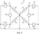
- FIG. 7is a circuit diagram of the strain gauge of FIG. 5A .
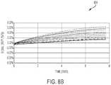
- FIG. 8Ais a graph showing testing data representing signal drift over time for strain gauges designed in accordance with the subject technology.
- FIG. 8Bis a graph showing testing data representing signal drift over time for prior art strain gauges.
- the subject technologyovercomes many of the prior art problems associated with pressure sensors.
- the subject technologyprovides a pressure sensor and corresponding strain gauge that significantly reduce signal drift as compared to prior art sensors.
- an “upper” surface of a partis merely meant to describe a surface that is separate from the “lower” surface of that same part.
- No words denoting orientationare used to describe an absolute orientation (i.e. where an “upper” part must always be on top).
- resistors, and other features describe herein which are numbered,are numbered only to facilitate a discussion of those features with respect to one another.
- the numbers of each componentdo not refer to any particular order (e.g. where one must become before two) and in various embodiments any number of one component can switch numbers with another numbered component. For example, if a first and second resistor are described, the second resistor could just as appropriately be deemed the first resistor while the resistor formerly called the first resistor is called the second resistor. Additionally, when a number of similar components are identified with like reference numerals (e.g. two resistors are given reference numerals 140 a and 140 b ) the components are sometimes referred to collectively with a single reference numeral (e.g. just 140 ).
- FIG. 1a cross sectional view of a prior art pressure sensor 100 is shown.
- the pressure sensoris configured for use within various applications, such as a motorized vehicle.
- the pressure sensor 100can measure the pressure of transmission fluid, brake fluid, or engine oil.
- a connector 110 , a housing 112 , and a solid steel port body 114are coupled together to enclose the other components of the pressure sensor 100 .
- a distal opening 116 in the port body 114allows fluid to flow from a fluid medium into an interior channel 118 defined by peripheral walls 120 of the port body 114 .
- Ridges 122 on the exterior 124 of the port body 114allow fixation of the distal end 126 of the port body 114 to a structure 128 surrounding the fluid medium, keeping the interior channel 118 fluidly connected to the fluid medium.
- the port body 114also includes a diaphragm 130 at a proximate end 132 of the interior channel 118 .
- the diaphragm 130is formed from a steel wall that is relatively thinner as compared to the peripheral walls 120 of the port body 114 .
- a strain gauge 134such as a microfused silicon strain gauge (MSG) is affixed to the top 136 of the diaphragm 130 , for example, by an adhesive or substrate layer.
- the strain gauge 134includes a number of sense elements, such as resistors or piezoresistive elements which change resistance as they flex in conjunction with the flexing of the diaphragm 130 .
- the resistance of the resistorsis relied upon to determine the pressure within the interior channel 118 , and thus, pressure within the pressure medium. This resistance can be calculated, for example, by configuring the strain gauge 134 and corresponding resistors to form a Wheatstone bridge.
- Connector pins 111allow signals for the strain gauge 134 to be delivered to external electronics (not shown herein).
- FIG. 2a schematic of the circuitry of a prior art strain gauge 134 forming a Wheatstone bridge is shown.
- the strain gauge 134 and related processing circuitryact to calculate a pressure based on the resistance of the resistors 140 .
- a voltage supply 142applies a voltage to the Wheatstone bridge.
- an electrical connectionis formed between the voltage supply 142 , a first bridge output voltage 144 , and a ground pad 146 .
- a first resistor 140 ais disposed on the electrical connection between the voltage supply 142 and the bridge output voltage 144 and a second resistor 140 b is disposed between the first bridge output voltage 144 and the ground pad 146 .
- the voltage supply 142is electrically connected to a second bridge output voltage 148 and the ground pad 146 .
- a third resistor 140 cis disposed on the electrical connection between the voltage supply 142 and the second bridge output voltage 148 and a fourth resistor 140 d is disposed between the second bridge output voltage 148 and the ground pad 146 .
- flexure of the diaphragm 130causes a change in resistance to one or more of the resistors 140 .
- a constant voltageis being input into the strain gauge 134 via the voltage supply 142 . Therefore a change in resistance of one of the resistors 140 will cause a corresponding change in one of the bridge output voltages 144 , 148 .
- the change in output voltageis used to calculate the amount of flexure in the diaphragm and corresponding pressure change within the channel 118 , and therefore, within the fluid medium.
- the term “Wheatstone bridge” as used hereinis used merely to refer to an arrangement of components, such as contact pads and resistors 140 , which work to generate a signal which can be relied upon to determine the resistance of one or more resistors 140 .
- the processing circuitry which is relied upon to ultimately determine pressuremay be separate from the strain gauge 134 shown herein.
- FIG. 3a block diagram showing the operation of a prior art strain gauge 134 is shown.
- the strain gauge 134is operating in a harsh environment, such as part of an automotive application, and is subject to a high temperature (i.e. above 100 degrees Celsius). In some cases, the temperature may even reach a very high temperature (i.e. above 110 degrees Celsius) or greater.
- the first resistor 140 ais positioned relatively closer to the supply voltage 142 as compared to the second resistor 140 b .
- the second resistor 140 bis positioned relatively closer to the ground 146 , as compared to the first resistor 140 a.
- the harsh environmenthas required the vehicle to continuously run, subjecting the strain gauge 134 to a high temperature.
- the strain gauge 134has remained powered on with the steel port grounded, resulting in the creation of a number of mobile ions 152 .
- the mobile ions 152will accumulate on the resistors 140 , and areas within those resistors 140 that are closest to the supply voltage 142 and furthest from the ground pad 146 . Disparate mobile ions 152 accumulate across the resistors 140 will result in a mobile ion distribution with an unbalanced resistance change which can create a charging effect on the resistors 140 leading to sensor signal drift.
- the distribution graphs 154 a , 154 b(generally 154 ) under each resistor 140 a , 140 b represent the strength of the mobile ion distribution across those resistors 140 a , 140 b .
- the height of the graphical depiction of the mobile ion distribution 154corresponds to the average total mobile ion 152 accumulation at the corresponding area of the resistor 140 (i.e. the area of each resistor 140 directly above that portion of the distribution graph 154 .
- the first resistor 140 abeing closer to the voltage supply 142 and further from the ground pad 146 , has a greater mobile ion accumulation, and thus a higher mobile ion distribution 154 a , than the mobile ion distribution 154 b of the second resistor 140 b .
- the mobile ion distribution graphs 154 a , 154 b of each resistor 140 a , 140 bincreases according to proximity to the voltage supply 142 and distance from the ground pad 146 .
- FIG. 4a cross sectional view of a pressure sensor 400 in accordance with the subject technology is shown.
- a connector 410 , a housing 412 , and a solid steel port body 414are coupled together to enclose the other components of the pressure sensor 400 .
- a distal opening 416 in the port body 414allows fluid to flow from a fluid medium into an interior channel 418 defined by peripheral walls 420 of the port body 414 .
- Ridges 422 on the exterior 424 of the port body 414allow fixation of the distal end 426 of the port body 414 to a structure 428 surrounding the fluid medium, keeping the interior channel 418 fluidly connected to the fluid medium.
- the port body 414also includes a diaphragm 430 at a proximate end 432 of the interior channel 418 .
- the diaphragm 430is formed from a steel wall that is relatively thinner as compared to the peripheral walls 420 of the port body 414 .
- a strain gauge 434such as an MSG, is affixed to the top 436 of the diaphragm 430 , for example, by an adhesive or substrate layer (e.g. a glass substrate 438 ).
- the strain gauge 434includes a number of sense elements, such as resistors 440 (see FIG. 5A ) or piezoresistive elements which change resistance as they flex in conjunction with the flexing of the diaphragm 430 .
- the resistance of the resistors 440is relied upon to determine the pressure within the interior channel 418 , and thus, pressure within the pressure medium.
- the strain gauge 432can transmit an output signal to external components for (not distinctly shown) for display or processing via connector pins 411 .
- the pressure sensor 400has some similar features to the prior art pressure sensor 100 , the most significant differences are described and shown herein.
- the resistors 440are directly attached to the port body 414 , the only intervening layer being a glass substrate 438 or an adhesive.
- the pressure sensor 400 of the subject technologyincludes a strain gauge 434 which is positioned half over the diaphragm 430 , and half over the thicker peripheral walls 420 of the port body 414 .
- a strain gauge 434which is positioned half over the diaphragm 430 , and half over the thicker peripheral walls 420 of the port body 414 .
- resistance of the resistors 440is relied upon to determine the pressure within the interior channel 118 , and thus, pressure within the pressure medium.
- the resistors 440are piezoresistive elements, the differential in resistance between the resistors 440 in tension and the resistors 440 in compression can be further relied upon to enhance sensing accuracy.
- FIGS. 5A and 5Ba top view of the mechanical configuration of a strain gauge 434 , as well as a simplified circuit diagram of a strain gauge 434 in accordance with the subject technology are shown, respectively. While only a strain gauge 434 is shown for simplicity, it should be noted that it is envisioned that the strain gauge 434 will be utilized in accordance with the other components shown and described herein.
- the strain gauge 434can be attached to a pressure sensor 400 via a glass substrate 438 , as shown in FIG. 4 . Fi
- the strain gauge 434contains four input/output pads (I/O) pads 442 , 444 , 448 , 450 and a centrally positioned ground pad 446 .
- the I/O pads 442 , 444 , 448 , 450are aligned along a lateral axis “x” and elongated along a longitudinal axis “y”, such that they are all parallel along the longitudinal axis y.
- the longitudinal axis ypasses lengthwise through the center of the ground pad 446 while the lateral axis x passes widthwise through the center of the ground pad 446 .
- the strain gauge 434also includes four resistors 440 a , 440 b , 440 c , 440 d (generally 440 ).
- a first resistor 440 aelectrically connects a first I/O pad 444 to the ground pad 446 .
- the first resistor 440 ais located on a first side 456 a of the longitudinal axis y and a first side 456 b of the lateral axis x.
- a second resistor 440 blocated on the first side 456 a of the longitudinal axis y and a second side 456 c of the lateral axis x, connects the second I/O pad 442 to the ground pad 446 .
- a third resistor 440 cpositioned on the second side 456 c of the lateral axis x and the second side 456 d of the longitudinal axis y, connects the third I/O pad 448 to the ground pad 446 .
- a fourth resistor 440 dpositioned on the first side 456 b of the first lateral axis x and the second side 456 d of the longitudinal axis y, connects the fourth I/O pad 450 to the ground pad 446 .
- the position of the resistors 440with respect to the x and y axes, can also be described as quadrants.
- the x and y axesform four quadrants with the first 440 a , second 440 b , third 440 c , and fourth 440 d resistors being positioned within the first 456 a , 456 b , second 456 a , 456 c , third 456 d , 456 c , and fourth 456 d , 456 b quadrants respectively.
- the four resistors 440can also be described as forming two pairs of resistors, the pairs being symmetrical about one or more of the axes x,y.
- the first resistor 440 a and the fourth resistor 440 dcan form a first resistor pair while the second resistor 440 b and the third resistor 440 c can form a second resistor pair.
- the first resistor pair and the second resistor pairare symmetrical about the lateral axis x.
- the first resistor 440 a and the second resistor 440 bcan form a first resistor pair while the third resistor 440 c and the fourth resistor 440 d form a second resistor pair.
- the first resistor pair and the second resistor pairwould then be symmetrical about the longitudinal axis y.
- This symmetrical resistor orientation within the strain gauge 434reduces pressure nonlinearity between the resistors 440 .
- the five pad 442 , 444 , 446 , 448 , 450 orientation, with symmetrical I/O pads 442 , 444 , 448 , 450 surrounding the central ground pad 446eases the wire bonding process, making assembly of the strain gauge 434 quicker and more cost efficient.
- the symmetrical resistor orientationalso allows the resistors to be more easily placed on a desired location of the port body 414 .
- the strain gauge 434can be placed with the first resistor 440 a and fourth resistor 440 d are placed the peripheral walls 420 of the strain gauge 434 , while the second resistor 440 b and third resistor 440 c are placed over the diaphragm 430 .
- fluid entering the channel 418will apply a pressure to the diaphragm 430 , causing the first resistor and the fourth resistor 440 d to be in compression while the second resistor 440 b and third resistor 440 c are in compression.
- FIG. 6a block diaphragm of the strain gauge 434 of FIGS. 5A-5B is shown.
- the strain gauge 434is operating in a harsh environment, such as part of an automotive application, and is subject to a high temperature (i.e. above 100 degrees Celsius). In some cases, the temperature may even reach a very high temperature (i.e. above 110 degrees Celsius) or greater.
- the strain gauge 434 and circuitryare affixed to the port body 414 via a glass substrate 438 .
- An input currentis being applied to the strain gauge 434 via the I/O pads 442 , 444 .
- the second resistor 440 bis positioned substantially equidistant from the ground 446 , as compared to the first resistor 440 a . Both resistors 440 , 440 b are also positioned substantially equidistant from their corresponding I/O pad 442 , 444 .
- the term “substantially” as used in the phrase “substantially equidistant” herein,is defined as between 0 to 200 micrometers.
- the port body 414is a conductive material electrically connected to the ground. Therefore the ground pad 446 of the strain gauge 434 is grounded by a connection between the ground pad 446 and the port body 414 .
- the harsh environmenthas resulted in the creation of a number of mobile ions 452 .
- the mobile ions 452will accumulate on the resistors 440 , and areas within those resistors 440 , that are closest to supply current from the I/O pads 442 , 444 and further from the ground 446 .
- the first and second resistors 440 a , 440 bare spaced from the ground pad 446 to urge uniform mobile ion 452 accumulation across the first and second resistors 440 a , 440 b .
- each resistor 440is spaced substantially equidistant from the ground pad 446 to urge uniform mobile ion 452 accumulation across the resistors 440 .
- Mobile ion 452 accumulation across the first resistor 440 ais graphically depicted by mobile ion distribution graph 454 a and the mobile ion 452 accumulation across the second resistor 440 b is graphically depicted by mobile ion distribution graph 454 b .
- the configuration of each resistor 440 being substantially equidistant from the ground pad 446reduces mobile ion 452 migration.
- the first resistor 440 ahas approximately the same mobile ion 452 accumulation, and approximately the same mobile ion distribution graph 454 a as the mobile ion 452 accumulation and distribution graph 454 b for the second resistor 440 b .
- the height of the graphical depictions 454 of the mobile ion distribution 454corresponds to average total mobile ion 452 accumulation at the corresponding area of each resistor 440 a , 440 b (e.g. the area of each resistor 440 a , 440 b at a similar distance from the central ground pad 446 ).
- Balanced mobile ion 452 accumulating across the resistors 440 a , 440 bresults in a balanced resistance charge (i.e. the first resistor 440 a is reducing at the same rate as the second resistor 440 b ). This advantageously prevents creation of a charging effect on the resistors 440 and reduces or eliminates sensor signal drift.
- FIG. 7a more complete circuit diagram of the strain gauge of FIGS. 5A-5B is shown.
- a first resistor 440 ais electrically connected between a first I/O pad 444 and a ground pad 446 .
- a second resistor 440 bis electrically connected between a second I/O pad 442 and the ground pad 446 .
- a third resistor 440 cis electrically connected between a third I/O pad 448 and the ground pad 446
- a fourth resistor 440 dis electrically connected between a fourth I/O pad 450 and the ground pad 446 .
- Each resistor 440is positioned to be substantially equidistant from the ground pad 446 to urge uniform mobile ion 452 accumulation across the resistors 440 .
- Four current sources 458 a , 458 b , 458 c , 458 d(generally 458 ), each provide a uniform, constant current to one of the I/O pads 442 , 444 , 448 , 450 .
- a first output 460 ais electrically connected between the first I/O pad 444 and the second I/O pad 442 and a second output 460 b is electrically connected between the third I/O pad 448 and the fourth I/O pad 450 , the output 460 configured to measure a change in voltage.
- the outputs 460sense a corresponding voltage change which can be used to calculate pressure.
- a constant voltagecan be applied as an input, instead of current sources 458 , and the outputs 460 can be configured to measure a change in current.
- the strain gauge 434could be configured with only resistors 440 a and 440 b , output 460 a , grounding pad 446 , and the first and second I/O pads 442 , 444 .
- the first resistor 440 awould be placed above the peripheral walls 420 of the port body 414 such that it would experience a compression force, while the second resistor 440 b would be placed above the diaphragm 430 to experience a tension force.
- the output 460 awould then measure the resistance differential (e.g.
- resistors 440 b , 440 awere placed in tension and compression, respectively.
- the third resistor 440 ccould be placed in tension while the fourth resistor 440 d is placed in compression, such that the output 460 b measures the resistance differential. Therefore having four resistors 440 allows for each pair of resistors (e.g. 440 a , 440 b and 440 c , 440 d ) to serve as a check on the other pair.
- FIG. 8A and FIG. 8Bgraphs 802 , 804 of test data showing the signal drift of various strain gauges are shown.
- Graph 802 of FIG. 8Arepresents the signal drift data of tests on a number of strain gauges configured in accordance with the subject technology
- graph 804 of FIG. 8Brepresents the signal drift of prior art strain gauges.
- a hot soak testwas performed at 140 degrees Celsius for 300 hours on powered strain gauges.
- the signal drift of prior art strain gauges (graph 804 ) at timesapproached 6.00% by the 8 th day of testing.
- the error of all strain gauges of the subject technologywas less than 0.2% at the 8 th day.
- the new designreduced signal drift by an average of approximately 95%.
- any functional elementmay perform fewer, or different, operations than those described with respect to the illustrated embodiment.
- functional elementse.g., electronics, input and output sources, connection pads, and the like
- shown as distinct for purposes of illustrationmay be incorporated within other functional elements in a particular implementation.
Landscapes
- Physics & Mathematics (AREA)
- General Physics & Mathematics (AREA)
- Electromagnetism (AREA)
- Measuring Fluid Pressure (AREA)
- Pressure Sensors (AREA)
Abstract
Description
Claims (20)
Priority Applications (5)
| Application Number | Priority Date | Filing Date | Title |
|---|---|---|---|
| US15/704,797US10557770B2 (en) | 2017-09-14 | 2017-09-14 | Pressure sensor with improved strain gauge |
| CN201811073961.XACN109506826B (en) | 2017-09-14 | 2018-09-14 | Pressure sensor with improved strain gauge |
| GB1815024.3AGB2568578B (en) | 2017-09-14 | 2018-09-14 | Pressure sensor with improved strain gauge |
| KR1020180110255AKR102587140B1 (en) | 2017-09-14 | 2018-09-14 | Pressure sensor with improved strain gauge |
| DE102018122522.9ADE102018122522A1 (en) | 2017-09-14 | 2018-09-14 | Pressure sensor with improved strain gauge |
Applications Claiming Priority (1)
| Application Number | Priority Date | Filing Date | Title |
|---|---|---|---|
| US15/704,797US10557770B2 (en) | 2017-09-14 | 2017-09-14 | Pressure sensor with improved strain gauge |
Publications (2)
| Publication Number | Publication Date |
|---|---|
| US20190078953A1 US20190078953A1 (en) | 2019-03-14 |
| US10557770B2true US10557770B2 (en) | 2020-02-11 |
Family
ID=64013383
Family Applications (1)
| Application Number | Title | Priority Date | Filing Date |
|---|---|---|---|
| US15/704,797Active2038-02-01US10557770B2 (en) | 2017-09-14 | 2017-09-14 | Pressure sensor with improved strain gauge |
Country Status (5)
| Country | Link |
|---|---|
| US (1) | US10557770B2 (en) |
| KR (1) | KR102587140B1 (en) |
| CN (1) | CN109506826B (en) |
| DE (1) | DE102018122522A1 (en) |
| GB (1) | GB2568578B (en) |
Families Citing this family (5)
| Publication number | Priority date | Publication date | Assignee | Title |
|---|---|---|---|---|
| US11137241B2 (en)* | 2019-03-27 | 2021-10-05 | Vishay Advanced Technologies, Ltd. | Three dimensional strain gage |
| WO2020231423A1 (en) | 2019-05-15 | 2020-11-19 | Hewlett-Packard Development Company, L.P. | Integrated circuits including strain gauge sensors |
| CN113865757B (en)* | 2021-09-16 | 2024-07-09 | 歌尔微电子股份有限公司 | Detection circuit, detection method and electronic equipment of piezoresistive pressure sensor |
| US11898920B2 (en)* | 2022-05-10 | 2024-02-13 | Sensata Technologies, Inc. | Electromagnetic interference absorbing sensor connector |
| EP4421467A1 (en) | 2023-02-27 | 2024-08-28 | Melexis Technologies NV | A sensor configuration |
Citations (176)
| Publication number | Priority date | Publication date | Assignee | Title |
|---|---|---|---|---|
| US4072058A (en) | 1976-05-03 | 1978-02-07 | Honeywell Inc. | Differential pressure transmitter with pressure sensor protection |
| US4131088A (en) | 1976-11-08 | 1978-12-26 | The Bendix Corporation | Multiple function pressure sensor |
| GB2066590A (en) | 1979-12-26 | 1981-07-08 | Teradyne Inc | Test pin |
| US4287772A (en) | 1978-05-18 | 1981-09-08 | Gulton Industries, Inc. | Strain gage transducer and process for fabricating same |
| US4347745A (en) | 1980-12-22 | 1982-09-07 | Bourns Instruments, Inc. | Pressure measuring apparatus |
| EP0085584A1 (en) | 1982-01-28 | 1983-08-10 | AEROSPATIALE Société Nationale Industrielle | Suspension for a two-wheel axle, with a torsion and anti-roll bars assembly for the same |
| US4400681A (en) | 1981-02-23 | 1983-08-23 | General Motors Corporation | Semiconductor pressure sensor with slanted resistors |
| US4462018A (en)* | 1982-11-05 | 1984-07-24 | Gulton Industries, Inc. | Semiconductor strain gauge with integral compensation resistors |
| US4771427A (en) | 1986-10-02 | 1988-09-13 | United Technologies Corporation | Equalization in redundant channels |
| US4817362A (en)* | 1986-04-24 | 1989-04-04 | Renishaw Plc | Probe for measuring workpieces and electrical connections therefor |
| US4825876A (en) | 1988-02-23 | 1989-05-02 | Abbott Laboratories | Encapsulated blood pressure transducer |
| US4888662A (en) | 1988-12-08 | 1989-12-19 | Texas Instruments Incorporated | High pressure package for pressure transducers |
| US4903164A (en) | 1988-12-08 | 1990-02-20 | Texas Instruments Incorporated | O-ring/back-up ring seal for high pressure transducers |
| US4967605A (en)* | 1987-04-24 | 1990-11-06 | Wacoh Corporation | Detector for force and acceleration using resistance element |
| US5060108A (en) | 1990-01-25 | 1991-10-22 | Texas Instruments Incorporated | Packaging and sealing for pressure transducer |
| US5101659A (en) | 1990-04-12 | 1992-04-07 | Nissan Motor Co., Ltd. | Mounting device for pressure sensor |
| US5101665A (en) | 1990-07-05 | 1992-04-07 | Mitsubishi Denki Kabushiki Kaisha | Semiconductor pressure sensor |
| US5144843A (en) | 1988-07-26 | 1992-09-08 | Hitachi Construction Machinery Co., Ltd. | Pressure sensor |
| US5173766A (en) | 1990-06-25 | 1992-12-22 | Lsi Logic Corporation | Semiconductor device package and method of making such a package |
| US5181417A (en) | 1989-07-10 | 1993-01-26 | Nippon Soken, Inc. | Pressure detecting device |
| US5184107A (en) | 1991-01-28 | 1993-02-02 | Honeywell, Inc. | Piezoresistive pressure transducer with a conductive elastomeric seal |
| US5184515A (en) | 1989-06-22 | 1993-02-09 | Ic Sensors, Inc. | Single diaphragm transducer with multiple sensing elements |
| US5209121A (en) | 1990-07-24 | 1993-05-11 | Pfister Messtechnik Gmbh | Pressure sensor |
| US5222397A (en) | 1990-11-28 | 1993-06-29 | Mitsubishi Denki Kabushiki Kaisha | Pressure sensor |
| US5231301A (en) | 1991-10-02 | 1993-07-27 | Lucas Novasensor | Semiconductor sensor with piezoresistors and improved electrostatic structures |
| DE4234289C1 (en) | 1992-10-12 | 1993-11-25 | Fibronix Sensoren Gmbh | Pressure sensor e.g. for use in corrosive media - has non-metallic sensor element fitted in chemically resistant polymeric housing contg. expansion preventing tube |
| US5284107A (en) | 1992-03-09 | 1994-02-08 | Noranda Inc. | Cable bolt monitoring device |
| JPH0637334A (en) | 1992-07-16 | 1994-02-10 | Copal Electron Co Ltd | Structure of pressure sensor |
| US5295307A (en)* | 1991-07-27 | 1994-03-22 | Renishaw Metrology Limited | Sensing circuit for position-sensing probe |
| US5331857A (en) | 1992-08-21 | 1994-07-26 | General Automotive Specialty Co., Inc. | Pressure transducer |
| US5349865A (en) | 1993-08-30 | 1994-09-27 | Kavlico Corporation | Wide-pressure-range, adaptable, simplified pressure transducer |
| US5425371A (en) | 1992-10-05 | 1995-06-20 | Metatech Corporation | Fiberoptic pressure transducer |
| DE4407212C1 (en) | 1992-10-12 | 1995-08-03 | Fibronix Sensoren Gmbh | Pressure sensor |
| US5448444A (en) | 1994-01-28 | 1995-09-05 | United Technologies Corporation | Capacitive pressure sensor having a reduced area dielectric spacer |
| US5457988A (en) | 1993-10-28 | 1995-10-17 | Panex Corporation | Side pocket mandrel pressure measuring system |
| US5587535A (en) | 1994-07-08 | 1996-12-24 | Fujikoki Mfg. Co., Ltd. | Pressure sensor including a pair of slidable contacts between a strain gage and a print circuit board |
| US5625151A (en) | 1994-12-27 | 1997-04-29 | Mitsubishi Denki Kabushiki Kaisha | Silicone oil-filled semiconductor pressure sensor |
| US5629486A (en) | 1996-01-25 | 1997-05-13 | Delco Electronics Corporation | Pressure sensor apparatus with integrated circuit mounted thereon |
| US5665921A (en) | 1995-03-31 | 1997-09-09 | Endress & Hauser Gmbh & Co. | Gas tight pressure sensor sealed with flexible metallic adaptor and having ceramic sensor element |
| US5741975A (en) | 1996-07-31 | 1998-04-21 | Motorola, Inc. | Media isolated differential pressure sensor and fluid injection method |
| US5802912A (en) | 1996-01-25 | 1998-09-08 | Delco Electronics Corporation | Electrical terminal apparatus |
| US5866822A (en)* | 1995-06-16 | 1999-02-02 | Robert Bosch Gmbh | Pressure sensor plate having a plurality of measuring diaphragms distributed in a matrix |
| US5869766A (en) | 1995-10-03 | 1999-02-09 | Nt International, Inc. | Non-contaminating pressure transducer module |
| US6033544A (en) | 1996-10-11 | 2000-03-07 | Sarnoff Corporation | Liquid distribution system |
| US6050145A (en) | 1995-04-28 | 2000-04-18 | Rosemount Inc. | Pressure transmitter with high pressure isolator mounting assembly |
| US6070883A (en) | 1995-12-21 | 2000-06-06 | Robert Bosch Gmbh | Sealing unit for a fuel pressure sensor |
| US6119524A (en) | 1998-03-19 | 2000-09-19 | Kobold; Klaus | Measuring indicator device |
| FR2791430A1 (en) | 1999-03-25 | 2000-09-29 | Denso Corp | Pressure sensor for measuring petrol pressure of injection system in car comprises rod with membrane, detection zone, casing, and fixings |
| EP1074827A2 (en) | 1999-08-03 | 2001-02-07 | Yamatake Corporation | Pressure sensor and method of manufacturing the same |
| US6204594B1 (en) | 1998-06-12 | 2001-03-20 | Cooper Automotive Products, Inc. | Spark plug with pressure sensor |
| US20010015402A1 (en) | 1999-12-24 | 2001-08-23 | Hiroyuki Murai | Installation structure of engine component with combustion pressure sensor in engine |
| US20010039837A1 (en) | 1997-07-25 | 2001-11-15 | Yukihiko Tanizawa | Pressure detecting apparatus with metallic diaphragm |
| US6351998B1 (en) | 2000-09-19 | 2002-03-05 | General Motors Corporation | Method for designing a load cell |
| US20020029639A1 (en) | 2000-01-19 | 2002-03-14 | Measurement Specialities, Inc. | Isolation technique for pressure sensing structure |
| US6389903B1 (en) | 1998-08-04 | 2002-05-21 | Denso Corporation | Pressure-detecting device coupling member with interchangeable connector part |
| WO2002042720A2 (en) | 2000-11-22 | 2002-05-30 | Smartsignal Corporation | Inferential signal generator for instrumented equipment and processes |
| EP1211497A2 (en) | 2000-11-21 | 2002-06-05 | Texas Instruments Incorporated | Capacitive pressure sensor apparatus |
| US20020073533A1 (en) | 2000-12-04 | 2002-06-20 | Kavlico Corporation | Very high pressure miniature sensing and mounting technique |
| US20020100948A1 (en) | 2001-01-31 | 2002-08-01 | Shinji Yoshihara | Semiconductor dynamic quantity sensor |
| US6439058B1 (en) | 1999-10-06 | 2002-08-27 | Denso Corporation | Semiconductor sensor |
| US6453747B1 (en) | 2000-01-12 | 2002-09-24 | Peter A. Weise | Hermetic pressure transducer |
| US20030033884A1 (en) | 2001-08-16 | 2003-02-20 | Harold Beekhuizen | Simplified capacitance pressure sensor |
| US6539787B1 (en) | 1999-10-28 | 2003-04-01 | Denso Corporation | Glow plug having a combustion pressure sensor |
| US6568276B1 (en) | 2000-08-04 | 2003-05-27 | Measurement Specialties, Inc. | Strain gauge based sensor with improved linearity |
| US20030150275A1 (en) | 2000-01-19 | 2003-08-14 | Wagner David E. | Isolation technique for pressure sensing structure |
| WO2003100371A1 (en) | 2002-05-25 | 2003-12-04 | Robert Bosch Gmbh | Pressure measuring device |
| US20040007074A1 (en) | 2002-07-10 | 2004-01-15 | Texas Instruments Incorporated | Hermetic pressure transducer |
| US20040007073A1 (en) | 2002-07-10 | 2004-01-15 | Texas Instruments Incorporated | Hermetic pressure transducer |
| US20040007075A1 (en) | 2002-07-10 | 2004-01-15 | Texas Instruments Incorporated | Hermetic pressure transducer |
| US20040015282A1 (en) | 2000-09-07 | 2004-01-22 | Babala Mike L. | High reliability pressure sensor |
| US20040020300A1 (en) | 2000-06-30 | 2004-02-05 | Ewald Boehler | Pressure transmitter |
| US6700174B1 (en) | 1997-09-25 | 2004-03-02 | Integrated Micromachines, Inc. | Batch fabricated semiconductor thin-film pressure sensor and method of making same |
| US20040132900A1 (en) | 2003-01-08 | 2004-07-08 | International Business Machines Corporation | Polyimide compositions and use thereof in ceramic product defect repair |
| USRE38557E1 (en) | 1995-10-03 | 2004-07-20 | Nt International, Inc. | Non-contaminating pressure transducer module |
| US20040146719A1 (en) | 2003-01-24 | 2004-07-29 | Delphi Technologies, Inc | Glass frit bond and process therefor |
| US20040147140A1 (en) | 2003-01-24 | 2004-07-29 | Zhineng Fan | Low inductance electrical contacts and lga connector system |
| US20040200286A1 (en) | 2002-06-22 | 2004-10-14 | Martin Mast | High pressure sensor comprising silicon membrane and solder layer |
| US20040255682A1 (en)* | 2003-06-18 | 2004-12-23 | Petrova Roumiana S. | Flexible thin film pressure sensor |
| US20050011273A1 (en) | 2003-07-18 | 2005-01-20 | Keiji Sasaki | Pressure sensor |
| US20050103111A1 (en) | 2003-11-13 | 2005-05-19 | Denso Corporation | Pressure sensor having sensor chip and signal processing circuit mounted on a common stem |
| EP1560012A1 (en) | 2004-01-30 | 2005-08-03 | Danfoss A/S | A pressure transmitter |
| US6945118B2 (en) | 2004-01-13 | 2005-09-20 | Honeywell International Inc. | Ceramic on metal pressure transducer |
| US6952042B2 (en) | 2002-06-17 | 2005-10-04 | Honeywell International, Inc. | Microelectromechanical device with integrated conductive shield |
| US20050252300A1 (en) | 2002-03-13 | 2005-11-17 | Ip Development, Llc | Pressure sensor with pressure translation |
| US6973837B2 (en)* | 2001-07-13 | 2005-12-13 | Barnett John D | Temperature compensated strain sensing apparatus |
| US20060000289A1 (en) | 1997-12-22 | 2006-01-05 | Mks Instruments | Pressure sensor for detecting small pressure differences and low pressures |
| US20060042395A1 (en) | 2004-08-27 | 2006-03-02 | Lepine David F | System and method for pressure measurement |
| US20060042394A1 (en) | 2004-08-27 | 2006-03-02 | Kosh William S | System and method for pressure measurement |
| US20060042393A1 (en) | 2004-08-27 | 2006-03-02 | Yoshikazu Kaneko | System and method for pressure measurement |
| US20060053894A1 (en) | 2004-09-16 | 2006-03-16 | Denso Corporation | Pressure sensor |
| US7021147B1 (en) | 2005-07-11 | 2006-04-04 | General Electric Company | Sensor package and method |
| DE102004048367A1 (en) | 2004-10-01 | 2006-04-06 | Endress + Hauser Gmbh + Co. Kg | Fluid filling method for pressure transducer, involves cooling down temperature of liquid below minimum working temperature of pressure transducer and providing membranes, and closing opening when overpressure is applied to membranes |
| US7032456B1 (en) | 2004-12-30 | 2006-04-25 | The United States Of America As Represented By The Secretary Of The Navy | Isostatic piezoresistive pressure transducer with temperature output |
| US20060090566A1 (en) | 2004-10-28 | 2006-05-04 | Denso Corporation | Pressure detection device |
| US20060123887A1 (en) | 2002-12-20 | 2006-06-15 | Yves Dordet | Apparatus for pressure detection in an engine combustion chamber |
| WO2006102460A1 (en) | 2005-03-22 | 2006-09-28 | Ametek Aerospace | Apparatus and methods for shielding integrated circuitry |
| US7114396B2 (en) | 2004-03-03 | 2006-10-03 | Denso Corporation | Pressure sensor |
| US20060278012A1 (en) | 2005-05-30 | 2006-12-14 | Mitsubishi Denki Kabushiki Kaisha | Semiconductor pressure sensor |
| US7197937B2 (en) | 2005-01-26 | 2007-04-03 | Sensata Technologies, Inc. | Hermetic pressure sensing device |
| US7207214B1 (en) | 2004-02-17 | 2007-04-24 | Wlodarczyk Marek T | Glow plug integrated pressure sensor |
| US20070113667A1 (en)* | 2005-11-10 | 2007-05-24 | Honeywell International Inc. | Method and system of providing power to a pressure and temperature sensing element |
| US20070148788A1 (en) | 2005-12-23 | 2007-06-28 | Delta Electronics, Inc. | Semiconductor piezoresistive sensor and operation method thereof |
| EP1826543A2 (en) | 2006-02-27 | 2007-08-29 | Auxitrol S.A. | Stress isolated pressure sensing die |
| US20070202628A1 (en) | 2006-02-24 | 2007-08-30 | Atmel Germany Gmbh | Manufacturing process for integrated piezo elements |
| US20070205776A1 (en) | 2006-03-01 | 2007-09-06 | Loadstar Sensors, Inc. | Cylindrical capacitive force sensing device and method |
| US7316164B2 (en) | 2005-01-19 | 2008-01-08 | Denso Corporation | Pressure detection device and manufacturing method of the same |
| US7383737B1 (en) | 2007-03-29 | 2008-06-10 | Delphi Technologies, Inc | Capacitive pressure sensor |
| US20080148860A1 (en) | 2006-12-20 | 2008-06-26 | Denso Corporation | Pressure sensor with sensing element disposed on stem |
| US7412894B2 (en) | 2003-08-29 | 2008-08-19 | Fuji Electric Device Technology Co., Ltd. | Pressure sensing device incorporating pressure sensing chip in resin case |
| US20080222884A1 (en) | 2007-03-14 | 2008-09-18 | Honeywell International Inc. | Packaging for chip-on-board pressure sensor |
| US20080262584A1 (en) | 2007-03-19 | 2008-10-23 | Bottomley Paul A | Methods and apparatus for fabricating leads with conductors and related flexible lead configurations |
| US20090071260A1 (en) | 2007-09-19 | 2009-03-19 | Speldrich Jamie W | Pressure sensor stress isolation pedestal |
| US20090075529A1 (en) | 2007-09-18 | 2009-03-19 | Johnston Charles J | Spring contact assembly |
| US7518234B1 (en) | 2002-10-03 | 2009-04-14 | The United States Of America As Represented By The Administrator Of The National Aeronautics And Space Admistration | MEMS direct chip attach packaging methodologies and apparatuses for harsh environments |
| US7555957B2 (en) | 2006-09-13 | 2009-07-07 | Denso Corporation | Pressure sensor equipped with pressure sensing diaphragm |
| US7578194B1 (en) | 2008-02-11 | 2009-08-25 | Sensata Technologies, Inc. | Differential fluid pressure measurement apparatus |
| US20090282926A1 (en) | 2008-04-30 | 2009-11-19 | Wolfgang Hauer | Pressure-sensor system |
| US20090315864A1 (en) | 2008-06-23 | 2009-12-24 | Silverbrook Research Pty Ltd | Electronic pen with retractable and replaceable cartridge |
| US20090320576A1 (en) | 2008-06-25 | 2009-12-31 | Marc Gerard Johan Borgers | Piezoresistive Pressure-Measuring Plug for a Combustion Engine |
| US20100052578A1 (en) | 2006-11-15 | 2010-03-04 | J&J Corp. | Subminiature linear vibrator |
| US7726197B2 (en) | 2006-04-26 | 2010-06-01 | Honeywell International Inc. | Force sensor package and method of forming same |
| US7739922B2 (en) | 2007-05-31 | 2010-06-22 | Minebea Co., Ltd. | Triaxial force sensor and triaxial force detection method |
| US20100192696A1 (en) | 2007-07-10 | 2010-08-05 | Michael Schlitzkus | Connection unit for a pressure measuring cell |
| US7775119B1 (en) | 2009-03-03 | 2010-08-17 | S3C, Inc. | Media-compatible electrically isolated pressure sensor for high temperature applications |
| US20100219487A1 (en) | 2006-10-06 | 2010-09-02 | Donis Dieter | Method for manufacturing a sensor component and sensor component |
| US20100239109A1 (en) | 2006-06-08 | 2010-09-23 | Nxp B.V. | Acoustic device and method of manufacturing same |
| US20100267291A1 (en) | 2009-04-20 | 2010-10-21 | Scott Chabineau-Lovgren | Swaging process for improved compliant contact electrical test performance |
| US20100281994A1 (en) | 2009-05-11 | 2010-11-11 | Honeywell International Inc. | Pressure sensing device for harsh environments |
| JP2010256187A (en) | 2009-04-24 | 2010-11-11 | Panasonic Electric Works Co Ltd | Pressure sensor |
| US20110088480A1 (en) | 2009-10-16 | 2011-04-21 | Silicon Micro Sensors Gmbh | Pressure sensor and use thereof in a fluid tank |
| US20110108322A1 (en) | 2008-07-04 | 2011-05-12 | Harry Kaiser | Pre-installation assembly for a contact arrangement of a sensor assembly |
| US20110153277A1 (en) | 2009-12-23 | 2011-06-23 | Liebherr-Werk Ehingen Gmbh | Sensor |
| US8024978B2 (en) | 2009-01-21 | 2011-09-27 | Honeywell International Inc. | Media isolated pressure transducer having boss comprising single metal diaphragm |
| US8056752B2 (en) | 2007-09-12 | 2011-11-15 | Carnevali Jeffrey D | Dripless lid for beverage container |
| EP2390641A2 (en) | 2010-05-27 | 2011-11-30 | Sensata Technologies, Inc. | Pressure Sensor |
| US20110290030A1 (en) | 2010-05-27 | 2011-12-01 | Willner Andrew F | Pressure sensor |
| WO2011155054A1 (en) | 2010-06-11 | 2011-12-15 | トヨタ自動車株式会社 | Control device for internal combustion engine |
| US20110320158A1 (en) | 2010-06-24 | 2011-12-29 | Endress + Hauser Conducts Gesellsschaft fur Mass- und Regeltechnik mbH + Co. KG | Method for adjusting a measuring device in process analysis technology |
| US8129624B2 (en) | 2010-05-27 | 2012-03-06 | Sensata Technologies, Inc. | Pressure sensor |
| US20120067130A1 (en) | 2010-09-22 | 2012-03-22 | Robert Bosch Gmbh | Pressure Sensor, in Particular for a Braking Apparatus |
| US8156816B2 (en) | 2010-05-27 | 2012-04-17 | Sensata Technologies, Inc. | Pressure sensor |
| US8164007B2 (en) | 2008-07-16 | 2012-04-24 | Honeywell International | Conductive elastomeric seal and method of fabricating the same |
| US8215176B2 (en) | 2009-05-27 | 2012-07-10 | Continental Automotive Systems, Inc. | Pressure sensor for harsh media sensing and flexible packaging |
| US8250909B2 (en) | 2006-02-21 | 2012-08-28 | Robert Bosch Gmbh | Pressure measuring device |
| US8258799B2 (en)* | 2008-11-07 | 2012-09-04 | The Charles Stark Draper Laboratory, Inc. | MEMS dosimeter |
| US20120227477A1 (en) | 2010-10-20 | 2012-09-13 | Marc Gerard Johan Borgers | Pressure-Measuring Plug for a Combustion Engine |
| US20130052936A1 (en) | 2011-08-31 | 2013-02-28 | John C. Jordan | Heating and cooling ventilation system |
| WO2013083320A1 (en) | 2011-12-08 | 2013-06-13 | Robert Bosch Gmbh | Pressure sensor arrangement for detecting a pressure of a fluid medium in a measuring space |
| WO2013110045A1 (en) | 2012-01-20 | 2013-07-25 | Hydra Electric Company | High dielectric strength and dc insulation for pressure sensors and switches |
| EP2620757A1 (en) | 2012-01-27 | 2013-07-31 | Sensata Technologies Massachusetts, Inc. | Small form factor microfused silicon strain gage (MSG) pressure sensor packaging |
| US8516897B1 (en) | 2012-02-21 | 2013-08-27 | Honeywell International Inc. | Pressure sensor |
| EP2637008A2 (en) | 2012-03-05 | 2013-09-11 | Honeywell International Inc. | Apparatus and processes for silicon on insulator mems pressure sensors |
| US20130248024A1 (en) | 2011-12-29 | 2013-09-26 | Parker-Hannifin Corporation | Electroactive polymer based pressure sensor |
| US20130264664A1 (en) | 2010-12-15 | 2013-10-10 | Panasonic Corporation | Semiconductor pressure sensor |
| CN103454032A (en) | 2013-08-16 | 2013-12-18 | 中国电子科技集团公司第四十八研究所 | Pressure sensitive core with thermistor |
| US20130336511A1 (en) | 2012-06-15 | 2013-12-19 | The Boeing Company | Micro-Sensor Package And Associated Method Of Assembling The Same |
| US20140130585A1 (en) | 2012-11-12 | 2014-05-15 | Marc Borgers | Pressure-measuring plug for a combustion engine |
| US20140130586A1 (en) | 2012-11-12 | 2014-05-15 | Cris Ruis Zwollo | Pressure-measuring plug for a combustion engine |
| US20140137654A1 (en)* | 2012-11-21 | 2014-05-22 | Robert Zwijze | Measuring device for measuring a physical quantity |
| US20140144206A1 (en) | 2011-07-01 | 2014-05-29 | Endress + Hauser Gmbh + Co. Kg | Method for operating an absolute, or relative, pressure sensor having a capacitive transducer |
| US20140219713A1 (en) | 2013-01-25 | 2014-08-07 | Bal Seal Engineering, Inc. | Coil springs with complex coil configurations, assemblies with coil springs, and related methods |
| WO2014132730A1 (en) | 2013-02-28 | 2014-09-04 | 日立オートモティブシステムズ株式会社 | Pressure detecting device |
| US20140260648A1 (en) | 2013-03-13 | 2014-09-18 | Fujikoki Corporation | Pressure sensor |
| US20140338448A1 (en) | 2012-02-09 | 2014-11-20 | Fuji Electric Co., Ltd. | Physical quantity sensor and method of manufacturing physical quantity sensor |
| EP2848908A1 (en) | 2013-09-16 | 2015-03-18 | Nxp B.V. | Capacitive pressure sensor and calibration method |
| US8984949B2 (en) | 2009-06-26 | 2015-03-24 | Trafag Ag | Pressure sensor measuring element and pressure sensor provided with the latter |
| US9003897B2 (en) | 2012-05-10 | 2015-04-14 | Honeywell International Inc. | Temperature compensated force sensor |
| US20150135853A1 (en) | 2013-11-18 | 2015-05-21 | Mark P. McNeal | Mems pressure sensor field shield layout for surface charge immunity in oil filled packaging |
| US9046436B2 (en) | 2012-03-27 | 2015-06-02 | Robert Bosch Gmbh | Sensor unit |
| US9063033B2 (en) | 2013-03-12 | 2015-06-23 | Solar Turbines Incorporated | Sensor housing for use with gas turbine engines |
| US20160025581A1 (en)* | 2012-11-26 | 2016-01-28 | Hitachi Automotive Systems, Ltd. | Pressure sensor |
| US20160133762A1 (en) | 2013-05-21 | 2016-05-12 | Jorge Vicente Blasco Claret | Monolithic integration of plenoptic lenses on photosensor substrates |
| US20160265998A1 (en) | 2015-03-12 | 2016-09-15 | Sensata Technologies, Inc. | Pressure transducer |
| US20160282205A1 (en) | 2015-03-26 | 2016-09-29 | Sensata Technologies, Inc. | Semiconductor strain gauge |
| US9689767B2 (en)* | 2013-12-11 | 2017-06-27 | Melexis Technologies Nv | Semiconductor pressure sensor |
| EP3315936A1 (en) | 2016-10-27 | 2018-05-02 | Surpass Industry Co., Ltd. | Pressure detection device |
Family Cites Families (4)
| Publication number | Priority date | Publication date | Assignee | Title |
|---|---|---|---|---|
| CN1024842C (en)* | 1989-08-25 | 1994-06-01 | 株式会社长野计器制作所 | Strain detection element and pressure transducer using the same |
| CN2541830Y (en)* | 2001-12-25 | 2003-03-26 | 湖南长沙索普测控技术有限公司 | Thin film strain resistance for peripheral fixed support circular plane diaphragm steel cup |
| CN204177507U (en)* | 2014-11-04 | 2015-02-25 | 徐兴才 | One is novel flushes mould resistive ceramic pressure sensor |
| CN109100080A (en)* | 2018-10-15 | 2018-12-28 | 伟业智芯(北京)科技有限公司 | Quick response diaphragm pressure sensor and its manufacturing method |
- 2017
- 2017-09-14USUS15/704,797patent/US10557770B2/enactiveActive
- 2018
- 2018-09-14CNCN201811073961.XApatent/CN109506826B/enactiveActive
- 2018-09-14KRKR1020180110255Apatent/KR102587140B1/enactiveActive
- 2018-09-14GBGB1815024.3Apatent/GB2568578B/enactiveActive
- 2018-09-14DEDE102018122522.9Apatent/DE102018122522A1/enactivePending
Patent Citations (195)
| Publication number | Priority date | Publication date | Assignee | Title |
|---|---|---|---|---|
| US4072058A (en) | 1976-05-03 | 1978-02-07 | Honeywell Inc. | Differential pressure transmitter with pressure sensor protection |
| US4131088A (en) | 1976-11-08 | 1978-12-26 | The Bendix Corporation | Multiple function pressure sensor |
| US4287772A (en) | 1978-05-18 | 1981-09-08 | Gulton Industries, Inc. | Strain gage transducer and process for fabricating same |
| GB2066590A (en) | 1979-12-26 | 1981-07-08 | Teradyne Inc | Test pin |
| US4347745A (en) | 1980-12-22 | 1982-09-07 | Bourns Instruments, Inc. | Pressure measuring apparatus |
| US4400681A (en) | 1981-02-23 | 1983-08-23 | General Motors Corporation | Semiconductor pressure sensor with slanted resistors |
| EP0085584A1 (en) | 1982-01-28 | 1983-08-10 | AEROSPATIALE Société Nationale Industrielle | Suspension for a two-wheel axle, with a torsion and anti-roll bars assembly for the same |
| US4462018A (en)* | 1982-11-05 | 1984-07-24 | Gulton Industries, Inc. | Semiconductor strain gauge with integral compensation resistors |
| US4817362A (en)* | 1986-04-24 | 1989-04-04 | Renishaw Plc | Probe for measuring workpieces and electrical connections therefor |
| US4771427A (en) | 1986-10-02 | 1988-09-13 | United Technologies Corporation | Equalization in redundant channels |
| US4967605A (en)* | 1987-04-24 | 1990-11-06 | Wacoh Corporation | Detector for force and acceleration using resistance element |
| US4825876A (en) | 1988-02-23 | 1989-05-02 | Abbott Laboratories | Encapsulated blood pressure transducer |
| US5144843A (en) | 1988-07-26 | 1992-09-08 | Hitachi Construction Machinery Co., Ltd. | Pressure sensor |
| US4903164A (en) | 1988-12-08 | 1990-02-20 | Texas Instruments Incorporated | O-ring/back-up ring seal for high pressure transducers |
| US4888662A (en) | 1988-12-08 | 1989-12-19 | Texas Instruments Incorporated | High pressure package for pressure transducers |
| US5184515A (en) | 1989-06-22 | 1993-02-09 | Ic Sensors, Inc. | Single diaphragm transducer with multiple sensing elements |
| US5181417A (en) | 1989-07-10 | 1993-01-26 | Nippon Soken, Inc. | Pressure detecting device |
| US5060108A (en) | 1990-01-25 | 1991-10-22 | Texas Instruments Incorporated | Packaging and sealing for pressure transducer |
| US5101659A (en) | 1990-04-12 | 1992-04-07 | Nissan Motor Co., Ltd. | Mounting device for pressure sensor |
| US5173766A (en) | 1990-06-25 | 1992-12-22 | Lsi Logic Corporation | Semiconductor device package and method of making such a package |
| US5101665A (en) | 1990-07-05 | 1992-04-07 | Mitsubishi Denki Kabushiki Kaisha | Semiconductor pressure sensor |
| US5209121A (en) | 1990-07-24 | 1993-05-11 | Pfister Messtechnik Gmbh | Pressure sensor |
| US5222397A (en) | 1990-11-28 | 1993-06-29 | Mitsubishi Denki Kabushiki Kaisha | Pressure sensor |
| US5184107A (en) | 1991-01-28 | 1993-02-02 | Honeywell, Inc. | Piezoresistive pressure transducer with a conductive elastomeric seal |
| US5295307A (en)* | 1991-07-27 | 1994-03-22 | Renishaw Metrology Limited | Sensing circuit for position-sensing probe |
| US5231301A (en) | 1991-10-02 | 1993-07-27 | Lucas Novasensor | Semiconductor sensor with piezoresistors and improved electrostatic structures |
| US5284107A (en) | 1992-03-09 | 1994-02-08 | Noranda Inc. | Cable bolt monitoring device |
| JPH0637334A (en) | 1992-07-16 | 1994-02-10 | Copal Electron Co Ltd | Structure of pressure sensor |
| US5331857A (en) | 1992-08-21 | 1994-07-26 | General Automotive Specialty Co., Inc. | Pressure transducer |
| US5425371A (en) | 1992-10-05 | 1995-06-20 | Metatech Corporation | Fiberoptic pressure transducer |
| DE4234289C1 (en) | 1992-10-12 | 1993-11-25 | Fibronix Sensoren Gmbh | Pressure sensor e.g. for use in corrosive media - has non-metallic sensor element fitted in chemically resistant polymeric housing contg. expansion preventing tube |
| DE4407212C1 (en) | 1992-10-12 | 1995-08-03 | Fibronix Sensoren Gmbh | Pressure sensor |
| US5349865A (en) | 1993-08-30 | 1994-09-27 | Kavlico Corporation | Wide-pressure-range, adaptable, simplified pressure transducer |
| US5457988A (en) | 1993-10-28 | 1995-10-17 | Panex Corporation | Side pocket mandrel pressure measuring system |
| US5448444A (en) | 1994-01-28 | 1995-09-05 | United Technologies Corporation | Capacitive pressure sensor having a reduced area dielectric spacer |
| US5587535A (en) | 1994-07-08 | 1996-12-24 | Fujikoki Mfg. Co., Ltd. | Pressure sensor including a pair of slidable contacts between a strain gage and a print circuit board |
| US5625151A (en) | 1994-12-27 | 1997-04-29 | Mitsubishi Denki Kabushiki Kaisha | Silicone oil-filled semiconductor pressure sensor |
| US5665921A (en) | 1995-03-31 | 1997-09-09 | Endress & Hauser Gmbh & Co. | Gas tight pressure sensor sealed with flexible metallic adaptor and having ceramic sensor element |
| US6050145A (en) | 1995-04-28 | 2000-04-18 | Rosemount Inc. | Pressure transmitter with high pressure isolator mounting assembly |
| US5866822A (en)* | 1995-06-16 | 1999-02-02 | Robert Bosch Gmbh | Pressure sensor plate having a plurality of measuring diaphragms distributed in a matrix |
| US5869766A (en) | 1995-10-03 | 1999-02-09 | Nt International, Inc. | Non-contaminating pressure transducer module |
| USRE38557E1 (en) | 1995-10-03 | 2004-07-20 | Nt International, Inc. | Non-contaminating pressure transducer module |
| US6070883A (en) | 1995-12-21 | 2000-06-06 | Robert Bosch Gmbh | Sealing unit for a fuel pressure sensor |
| US5802912A (en) | 1996-01-25 | 1998-09-08 | Delco Electronics Corporation | Electrical terminal apparatus |
| US5629486A (en) | 1996-01-25 | 1997-05-13 | Delco Electronics Corporation | Pressure sensor apparatus with integrated circuit mounted thereon |
| US5741975A (en) | 1996-07-31 | 1998-04-21 | Motorola, Inc. | Media isolated differential pressure sensor and fluid injection method |
| US6033544A (en) | 1996-10-11 | 2000-03-07 | Sarnoff Corporation | Liquid distribution system |
| US20010039837A1 (en) | 1997-07-25 | 2001-11-15 | Yukihiko Tanizawa | Pressure detecting apparatus with metallic diaphragm |
| US6700174B1 (en) | 1997-09-25 | 2004-03-02 | Integrated Micromachines, Inc. | Batch fabricated semiconductor thin-film pressure sensor and method of making same |
| US20060000289A1 (en) | 1997-12-22 | 2006-01-05 | Mks Instruments | Pressure sensor for detecting small pressure differences and low pressures |
| US6119524A (en) | 1998-03-19 | 2000-09-19 | Kobold; Klaus | Measuring indicator device |
| US6204594B1 (en) | 1998-06-12 | 2001-03-20 | Cooper Automotive Products, Inc. | Spark plug with pressure sensor |
| US6389903B1 (en) | 1998-08-04 | 2002-05-21 | Denso Corporation | Pressure-detecting device coupling member with interchangeable connector part |
| FR2791430A1 (en) | 1999-03-25 | 2000-09-29 | Denso Corp | Pressure sensor for measuring petrol pressure of injection system in car comprises rod with membrane, detection zone, casing, and fixings |
| EP1074827A2 (en) | 1999-08-03 | 2001-02-07 | Yamatake Corporation | Pressure sensor and method of manufacturing the same |
| US6439058B1 (en) | 1999-10-06 | 2002-08-27 | Denso Corporation | Semiconductor sensor |
| US6539787B1 (en) | 1999-10-28 | 2003-04-01 | Denso Corporation | Glow plug having a combustion pressure sensor |
| US6411038B2 (en) | 1999-12-24 | 2002-06-25 | Denso Corporation | Installation structure of engine component with combustion pressure sensor in engine |
| US20010015402A1 (en) | 1999-12-24 | 2001-08-23 | Hiroyuki Murai | Installation structure of engine component with combustion pressure sensor in engine |
| US6453747B1 (en) | 2000-01-12 | 2002-09-24 | Peter A. Weise | Hermetic pressure transducer |
| US20030150275A1 (en) | 2000-01-19 | 2003-08-14 | Wagner David E. | Isolation technique for pressure sensing structure |
| US20020029639A1 (en) | 2000-01-19 | 2002-03-14 | Measurement Specialities, Inc. | Isolation technique for pressure sensing structure |
| US20040020300A1 (en) | 2000-06-30 | 2004-02-05 | Ewald Boehler | Pressure transmitter |
| US6568276B1 (en) | 2000-08-04 | 2003-05-27 | Measurement Specialties, Inc. | Strain gauge based sensor with improved linearity |
| US20040015282A1 (en) | 2000-09-07 | 2004-01-22 | Babala Mike L. | High reliability pressure sensor |
| US6351998B1 (en) | 2000-09-19 | 2002-03-05 | General Motors Corporation | Method for designing a load cell |
| US6487911B1 (en) | 2000-11-21 | 2002-12-03 | Texas Instruments Incorporated | Pressure sensor apparatus |
| EP1211497A2 (en) | 2000-11-21 | 2002-06-05 | Texas Instruments Incorporated | Capacitive pressure sensor apparatus |
| US6876943B2 (en) | 2000-11-22 | 2005-04-05 | Smartsignal Corporation | Inferential signal generator for instrumented equipment and processes |
| WO2002042720A2 (en) | 2000-11-22 | 2002-05-30 | Smartsignal Corporation | Inferential signal generator for instrumented equipment and processes |
| US20020073533A1 (en) | 2000-12-04 | 2002-06-20 | Kavlico Corporation | Very high pressure miniature sensing and mounting technique |
| US20020100948A1 (en) | 2001-01-31 | 2002-08-01 | Shinji Yoshihara | Semiconductor dynamic quantity sensor |
| US6973837B2 (en)* | 2001-07-13 | 2005-12-13 | Barnett John D | Temperature compensated strain sensing apparatus |
| US6536287B2 (en) | 2001-08-16 | 2003-03-25 | Honeywell International, Inc. | Simplified capacitance pressure sensor |
| US20030033884A1 (en) | 2001-08-16 | 2003-02-20 | Harold Beekhuizen | Simplified capacitance pressure sensor |
| US20050252300A1 (en) | 2002-03-13 | 2005-11-17 | Ip Development, Llc | Pressure sensor with pressure translation |
| WO2003100371A1 (en) | 2002-05-25 | 2003-12-04 | Robert Bosch Gmbh | Pressure measuring device |
| US6952042B2 (en) | 2002-06-17 | 2005-10-04 | Honeywell International, Inc. | Microelectromechanical device with integrated conductive shield |
| US20040200286A1 (en) | 2002-06-22 | 2004-10-14 | Martin Mast | High pressure sensor comprising silicon membrane and solder layer |
| US6715357B2 (en) | 2002-07-10 | 2004-04-06 | Texas Instruments Incorporated | Hermetic pressure transducer |
| US20040007074A1 (en) | 2002-07-10 | 2004-01-15 | Texas Instruments Incorporated | Hermetic pressure transducer |
| US6763724B2 (en) | 2002-07-10 | 2004-07-20 | Texas Instruments Incorporated | Hermetic pressure transducer |
| US20040007073A1 (en) | 2002-07-10 | 2004-01-15 | Texas Instruments Incorporated | Hermetic pressure transducer |
| US20040007075A1 (en) | 2002-07-10 | 2004-01-15 | Texas Instruments Incorporated | Hermetic pressure transducer |
| US7518234B1 (en) | 2002-10-03 | 2009-04-14 | The United States Of America As Represented By The Administrator Of The National Aeronautics And Space Admistration | MEMS direct chip attach packaging methodologies and apparatuses for harsh environments |
| US20060123887A1 (en) | 2002-12-20 | 2006-06-15 | Yves Dordet | Apparatus for pressure detection in an engine combustion chamber |
| US20040132900A1 (en) | 2003-01-08 | 2004-07-08 | International Business Machines Corporation | Polyimide compositions and use thereof in ceramic product defect repair |
| US20070154631A1 (en) | 2003-01-08 | 2007-07-05 | International Business Machines Corporation | Polyimide compositions and use thereof in ceramic product defect repair |
| US20040146719A1 (en) | 2003-01-24 | 2004-07-29 | Delphi Technologies, Inc | Glass frit bond and process therefor |
| US20040147140A1 (en) | 2003-01-24 | 2004-07-29 | Zhineng Fan | Low inductance electrical contacts and lga connector system |
| US20040255682A1 (en)* | 2003-06-18 | 2004-12-23 | Petrova Roumiana S. | Flexible thin film pressure sensor |
| US20050011273A1 (en) | 2003-07-18 | 2005-01-20 | Keiji Sasaki | Pressure sensor |
| US7412894B2 (en) | 2003-08-29 | 2008-08-19 | Fuji Electric Device Technology Co., Ltd. | Pressure sensing device incorporating pressure sensing chip in resin case |
| US20050103111A1 (en) | 2003-11-13 | 2005-05-19 | Denso Corporation | Pressure sensor having sensor chip and signal processing circuit mounted on a common stem |
| US6945118B2 (en) | 2004-01-13 | 2005-09-20 | Honeywell International Inc. | Ceramic on metal pressure transducer |
| EP1560012A1 (en) | 2004-01-30 | 2005-08-03 | Danfoss A/S | A pressure transmitter |
| US7207214B1 (en) | 2004-02-17 | 2007-04-24 | Wlodarczyk Marek T | Glow plug integrated pressure sensor |
| US7114396B2 (en) | 2004-03-03 | 2006-10-03 | Denso Corporation | Pressure sensor |
| US20060042393A1 (en) | 2004-08-27 | 2006-03-02 | Yoshikazu Kaneko | System and method for pressure measurement |
| US20060042394A1 (en) | 2004-08-27 | 2006-03-02 | Kosh William S | System and method for pressure measurement |
| US20060042395A1 (en) | 2004-08-27 | 2006-03-02 | Lepine David F | System and method for pressure measurement |
| US20060053894A1 (en) | 2004-09-16 | 2006-03-16 | Denso Corporation | Pressure sensor |
| DE102004048367A1 (en) | 2004-10-01 | 2006-04-06 | Endress + Hauser Gmbh + Co. Kg | Fluid filling method for pressure transducer, involves cooling down temperature of liquid below minimum working temperature of pressure transducer and providing membranes, and closing opening when overpressure is applied to membranes |
| US7302855B2 (en) | 2004-10-28 | 2007-12-04 | Denso Corporation | Pressure detection device |
| US20060090566A1 (en) | 2004-10-28 | 2006-05-04 | Denso Corporation | Pressure detection device |
| US7032456B1 (en) | 2004-12-30 | 2006-04-25 | The United States Of America As Represented By The Secretary Of The Navy | Isostatic piezoresistive pressure transducer with temperature output |
| US7316164B2 (en) | 2005-01-19 | 2008-01-08 | Denso Corporation | Pressure detection device and manufacturing method of the same |
| US7197937B2 (en) | 2005-01-26 | 2007-04-03 | Sensata Technologies, Inc. | Hermetic pressure sensing device |
| US20060214202A1 (en) | 2005-03-22 | 2006-09-28 | Zorich Robert S | Apparatus and methods for shielding integrated circuitry |
| WO2006102460A1 (en) | 2005-03-22 | 2006-09-28 | Ametek Aerospace | Apparatus and methods for shielding integrated circuitry |
| US20060278012A1 (en) | 2005-05-30 | 2006-12-14 | Mitsubishi Denki Kabushiki Kaisha | Semiconductor pressure sensor |
| US7021147B1 (en) | 2005-07-11 | 2006-04-04 | General Electric Company | Sensor package and method |
| US20070113667A1 (en)* | 2005-11-10 | 2007-05-24 | Honeywell International Inc. | Method and system of providing power to a pressure and temperature sensing element |
| US20070148788A1 (en) | 2005-12-23 | 2007-06-28 | Delta Electronics, Inc. | Semiconductor piezoresistive sensor and operation method thereof |
| US8250909B2 (en) | 2006-02-21 | 2012-08-28 | Robert Bosch Gmbh | Pressure measuring device |
| US20070202628A1 (en) | 2006-02-24 | 2007-08-30 | Atmel Germany Gmbh | Manufacturing process for integrated piezo elements |
| EP1826543A2 (en) | 2006-02-27 | 2007-08-29 | Auxitrol S.A. | Stress isolated pressure sensing die |
| US20070205776A1 (en) | 2006-03-01 | 2007-09-06 | Loadstar Sensors, Inc. | Cylindrical capacitive force sensing device and method |
| US7570065B2 (en) | 2006-03-01 | 2009-08-04 | Loadstar Sensors Inc | Cylindrical capacitive force sensing device and method |
| US7726197B2 (en) | 2006-04-26 | 2010-06-01 | Honeywell International Inc. | Force sensor package and method of forming same |
| US20100239109A1 (en) | 2006-06-08 | 2010-09-23 | Nxp B.V. | Acoustic device and method of manufacturing same |
| US7555957B2 (en) | 2006-09-13 | 2009-07-07 | Denso Corporation | Pressure sensor equipped with pressure sensing diaphragm |
| US20100219487A1 (en) | 2006-10-06 | 2010-09-02 | Donis Dieter | Method for manufacturing a sensor component and sensor component |
| US20100052578A1 (en) | 2006-11-15 | 2010-03-04 | J&J Corp. | Subminiature linear vibrator |
| US20080148860A1 (en) | 2006-12-20 | 2008-06-26 | Denso Corporation | Pressure sensor with sensing element disposed on stem |
| US20080222884A1 (en) | 2007-03-14 | 2008-09-18 | Honeywell International Inc. | Packaging for chip-on-board pressure sensor |
| US20080262584A1 (en) | 2007-03-19 | 2008-10-23 | Bottomley Paul A | Methods and apparatus for fabricating leads with conductors and related flexible lead configurations |
| US7383737B1 (en) | 2007-03-29 | 2008-06-10 | Delphi Technologies, Inc | Capacitive pressure sensor |
| US7739922B2 (en) | 2007-05-31 | 2010-06-22 | Minebea Co., Ltd. | Triaxial force sensor and triaxial force detection method |
| US8104357B2 (en) | 2007-07-10 | 2012-01-31 | Robert Bosch Gmbh | Connection unit for a pressure measuring cell |
| US20100192696A1 (en) | 2007-07-10 | 2010-08-05 | Michael Schlitzkus | Connection unit for a pressure measuring cell |
| US8056752B2 (en) | 2007-09-12 | 2011-11-15 | Carnevali Jeffrey D | Dripless lid for beverage container |
| US20090075529A1 (en) | 2007-09-18 | 2009-03-19 | Johnston Charles J | Spring contact assembly |
| US20090071260A1 (en) | 2007-09-19 | 2009-03-19 | Speldrich Jamie W | Pressure sensor stress isolation pedestal |
| US7578194B1 (en) | 2008-02-11 | 2009-08-25 | Sensata Technologies, Inc. | Differential fluid pressure measurement apparatus |
| US20090282926A1 (en) | 2008-04-30 | 2009-11-19 | Wolfgang Hauer | Pressure-sensor system |
| US20090315864A1 (en) | 2008-06-23 | 2009-12-24 | Silverbrook Research Pty Ltd | Electronic pen with retractable and replaceable cartridge |
| US8297115B2 (en) | 2008-06-25 | 2012-10-30 | Sensata Technologies, Inc. | Piezoresistive pressure-measuring plug for a combustion engine |
| US20090320576A1 (en) | 2008-06-25 | 2009-12-31 | Marc Gerard Johan Borgers | Piezoresistive Pressure-Measuring Plug for a Combustion Engine |
| US20110108322A1 (en) | 2008-07-04 | 2011-05-12 | Harry Kaiser | Pre-installation assembly for a contact arrangement of a sensor assembly |
| US8164007B2 (en) | 2008-07-16 | 2012-04-24 | Honeywell International | Conductive elastomeric seal and method of fabricating the same |
| US8258799B2 (en)* | 2008-11-07 | 2012-09-04 | The Charles Stark Draper Laboratory, Inc. | MEMS dosimeter |
| US8024978B2 (en) | 2009-01-21 | 2011-09-27 | Honeywell International Inc. | Media isolated pressure transducer having boss comprising single metal diaphragm |
| US8627559B2 (en) | 2009-03-03 | 2014-01-14 | S3C, Inc. | Media-compatible electrically isolated pressure sensor for high temperature applications |
| US7775119B1 (en) | 2009-03-03 | 2010-08-17 | S3C, Inc. | Media-compatible electrically isolated pressure sensor for high temperature applications |
| US20100267291A1 (en) | 2009-04-20 | 2010-10-21 | Scott Chabineau-Lovgren | Swaging process for improved compliant contact electrical test performance |
| JP2010256187A (en) | 2009-04-24 | 2010-11-11 | Panasonic Electric Works Co Ltd | Pressure sensor |
| US20100281994A1 (en) | 2009-05-11 | 2010-11-11 | Honeywell International Inc. | Pressure sensing device for harsh environments |
| US8215176B2 (en) | 2009-05-27 | 2012-07-10 | Continental Automotive Systems, Inc. | Pressure sensor for harsh media sensing and flexible packaging |
| US8984949B2 (en) | 2009-06-26 | 2015-03-24 | Trafag Ag | Pressure sensor measuring element and pressure sensor provided with the latter |
| US20110088480A1 (en) | 2009-10-16 | 2011-04-21 | Silicon Micro Sensors Gmbh | Pressure sensor and use thereof in a fluid tank |
| US20110153277A1 (en) | 2009-12-23 | 2011-06-23 | Liebherr-Werk Ehingen Gmbh | Sensor |
| US8129624B2 (en) | 2010-05-27 | 2012-03-06 | Sensata Technologies, Inc. | Pressure sensor |
| EP2390641A2 (en) | 2010-05-27 | 2011-11-30 | Sensata Technologies, Inc. | Pressure Sensor |
| US20110290030A1 (en) | 2010-05-27 | 2011-12-01 | Willner Andrew F | Pressure sensor |
| US8156816B2 (en) | 2010-05-27 | 2012-04-17 | Sensata Technologies, Inc. | Pressure sensor |
| WO2011155054A1 (en) | 2010-06-11 | 2011-12-15 | トヨタ自動車株式会社 | Control device for internal combustion engine |
| US20130073189A1 (en) | 2010-06-11 | 2013-03-21 | Toyota Jidosha Kabushiki Kaisha | Control apparatus for internal combustion engine |
| US20110320158A1 (en) | 2010-06-24 | 2011-12-29 | Endress + Hauser Conducts Gesellsschaft fur Mass- und Regeltechnik mbH + Co. KG | Method for adjusting a measuring device in process analysis technology |
| US20120067130A1 (en) | 2010-09-22 | 2012-03-22 | Robert Bosch Gmbh | Pressure Sensor, in Particular for a Braking Apparatus |
| US8671767B2 (en) | 2010-09-22 | 2014-03-18 | Robert Bosch Gmbh | Pressure sensor, in particular for a braking apparatus |
| US20120227477A1 (en) | 2010-10-20 | 2012-09-13 | Marc Gerard Johan Borgers | Pressure-Measuring Plug for a Combustion Engine |
| US8429956B2 (en) | 2010-10-20 | 2013-04-30 | Sensata Technologies, Inc. | Pressure-measuring plug for a combustion engine |
| US20130264664A1 (en) | 2010-12-15 | 2013-10-10 | Panasonic Corporation | Semiconductor pressure sensor |
| US20140144206A1 (en) | 2011-07-01 | 2014-05-29 | Endress + Hauser Gmbh + Co. Kg | Method for operating an absolute, or relative, pressure sensor having a capacitive transducer |
| US20130052936A1 (en) | 2011-08-31 | 2013-02-28 | John C. Jordan | Heating and cooling ventilation system |
| WO2013083320A1 (en) | 2011-12-08 | 2013-06-13 | Robert Bosch Gmbh | Pressure sensor arrangement for detecting a pressure of a fluid medium in a measuring space |
| US20130248024A1 (en) | 2011-12-29 | 2013-09-26 | Parker-Hannifin Corporation | Electroactive polymer based pressure sensor |
| WO2013110045A1 (en) | 2012-01-20 | 2013-07-25 | Hydra Electric Company | High dielectric strength and dc insulation for pressure sensors and switches |
| EP2620757A1 (en) | 2012-01-27 | 2013-07-31 | Sensata Technologies Massachusetts, Inc. | Small form factor microfused silicon strain gage (MSG) pressure sensor packaging |
| US20130192379A1 (en) | 2012-01-27 | 2013-08-01 | Neil S. Petrarca | Small form factor microfused silicon strain gage (msg) pressure sensor packaging |
| US20140338448A1 (en) | 2012-02-09 | 2014-11-20 | Fuji Electric Co., Ltd. | Physical quantity sensor and method of manufacturing physical quantity sensor |
| US8516897B1 (en) | 2012-02-21 | 2013-08-27 | Honeywell International Inc. | Pressure sensor |
| EP2637008A2 (en) | 2012-03-05 | 2013-09-11 | Honeywell International Inc. | Apparatus and processes for silicon on insulator mems pressure sensors |
| US9046436B2 (en) | 2012-03-27 | 2015-06-02 | Robert Bosch Gmbh | Sensor unit |
| US9003897B2 (en) | 2012-05-10 | 2015-04-14 | Honeywell International Inc. | Temperature compensated force sensor |
| US20130336511A1 (en) | 2012-06-15 | 2013-12-19 | The Boeing Company | Micro-Sensor Package And Associated Method Of Assembling The Same |
| US20140130586A1 (en) | 2012-11-12 | 2014-05-15 | Cris Ruis Zwollo | Pressure-measuring plug for a combustion engine |
| US20140130585A1 (en) | 2012-11-12 | 2014-05-15 | Marc Borgers | Pressure-measuring plug for a combustion engine |
| US8950247B2 (en) | 2012-11-12 | 2015-02-10 | Sensata Technologies, Inc. | Pressure-measuring plug for a combustion engine |
| US20140137654A1 (en)* | 2012-11-21 | 2014-05-22 | Robert Zwijze | Measuring device for measuring a physical quantity |
| US20160025581A1 (en)* | 2012-11-26 | 2016-01-28 | Hitachi Automotive Systems, Ltd. | Pressure sensor |
| US20140219713A1 (en) | 2013-01-25 | 2014-08-07 | Bal Seal Engineering, Inc. | Coil springs with complex coil configurations, assemblies with coil springs, and related methods |
| US20150377729A1 (en) | 2013-02-28 | 2015-12-31 | Hitachi Automotive Systems, Ltd. | Pressure detecting device |
| WO2014132730A1 (en) | 2013-02-28 | 2014-09-04 | 日立オートモティブシステムズ株式会社 | Pressure detecting device |
| US9063033B2 (en) | 2013-03-12 | 2015-06-23 | Solar Turbines Incorporated | Sensor housing for use with gas turbine engines |
| US20140260648A1 (en) | 2013-03-13 | 2014-09-18 | Fujikoki Corporation | Pressure sensor |
| US20160133762A1 (en) | 2013-05-21 | 2016-05-12 | Jorge Vicente Blasco Claret | Monolithic integration of plenoptic lenses on photosensor substrates |
| CN103454032A (en) | 2013-08-16 | 2013-12-18 | 中国电子科技集团公司第四十八研究所 | Pressure sensitive core with thermistor |
| EP2848908A1 (en) | 2013-09-16 | 2015-03-18 | Nxp B.V. | Capacitive pressure sensor and calibration method |
| US20150135853A1 (en) | 2013-11-18 | 2015-05-21 | Mark P. McNeal | Mems pressure sensor field shield layout for surface charge immunity in oil filled packaging |
| US9689767B2 (en)* | 2013-12-11 | 2017-06-27 | Melexis Technologies Nv | Semiconductor pressure sensor |
| US20160265998A1 (en) | 2015-03-12 | 2016-09-15 | Sensata Technologies, Inc. | Pressure transducer |
| US20160282205A1 (en) | 2015-03-26 | 2016-09-29 | Sensata Technologies, Inc. | Semiconductor strain gauge |
| EP3315936A1 (en) | 2016-10-27 | 2018-05-02 | Surpass Industry Co., Ltd. | Pressure detection device |
Also Published As
| Publication number | Publication date |
|---|---|
| DE102018122522A1 (en) | 2019-03-14 |
| GB2568578A (en) | 2019-05-22 |
| CN109506826A (en) | 2019-03-22 |
| GB201815024D0 (en) | 2018-10-31 |
| GB2568578B (en) | 2020-10-07 |
| CN109506826B (en) | 2022-01-14 |
| KR20190030628A (en) | 2019-03-22 |
| US20190078953A1 (en) | 2019-03-14 |
| KR102587140B1 (en) | 2023-10-06 |
Similar Documents
| Publication | Publication Date | Title |
|---|---|---|
| US10557770B2 (en) | Pressure sensor with improved strain gauge | |
| EP3710800B1 (en) | Split bridge circuit force sensor | |
| US9513182B2 (en) | Pressure sensor having multiple piezoresistive elements | |
| CN101180526A (en) | Pressure sensor using a compressible sensor body | |
| KR20040079323A (en) | Semiconductor pressure sensor having diaphragm | |
| EP2735855A1 (en) | A measuring device for measuring a physical quantity | |
| JP6203850B2 (en) | Distortion transmitter | |
| US20130126249A1 (en) | Load cell and applications thereof | |
| US3411361A (en) | Sealed beam sensors | |
| EP3742146A1 (en) | Micromechanical redundant piezoresistive array pressure sensor | |
| KR20190072431A (en) | Wim sensor and method for producing the wim sensor | |
| KR20110013224A (en) | Touch device and its control method | |
| US8950258B2 (en) | Micromechanical angular acceleration sensor and method for measuring an angular acceleration | |
| WO2020175155A1 (en) | Pressure sensor | |
| US20170102282A1 (en) | Strain sensor, and load detection device using same | |
| US3269187A (en) | Differential pressure transducer | |
| JP2003214967A (en) | Bridge circuit type sensor element | |
| US11415405B2 (en) | Strain gauge having unbalanced bias for single sided applications | |
| CN107250751B (en) | Hydraulic sensors, hydraulic control units and components, and vehicle braking systems | |
| CN113677970B (en) | Sensor for detecting pressure, fill level, density, temperature, mass and flow | |
| US10718795B2 (en) | Detecting device | |
| CN107290100A (en) | Pressure sensor | |
| US3473375A (en) | Strain gage transducer | |
| JP2021099290A (en) | Flow detector and pump system | |
| EP4421467A1 (en) | A sensor configuration |
Legal Events
| Date | Code | Title | Description |
|---|---|---|---|
| FEPP | Fee payment procedure | Free format text:ENTITY STATUS SET TO UNDISCOUNTED (ORIGINAL EVENT CODE: BIG.); ENTITY STATUS OF PATENT OWNER: LARGE ENTITY | |
| AS | Assignment | Owner name:SENSATA TECHNOLOGIES, INC., MASSACHUSETTS Free format text:ASSIGNMENT OF ASSIGNORS INTEREST;ASSIGNORS:HUO, SHIHONG;WOLF, ERIC A.;PETRARCA, NEIL S.;REEL/FRAME:043599/0264 Effective date:20170913 | |
| STPP | Information on status: patent application and granting procedure in general | Free format text:DOCKETED NEW CASE - READY FOR EXAMINATION | |
| STPP | Information on status: patent application and granting procedure in general | Free format text:NON FINAL ACTION MAILED | |
| STPP | Information on status: patent application and granting procedure in general | Free format text:RESPONSE TO NON-FINAL OFFICE ACTION ENTERED AND FORWARDED TO EXAMINER | |
| STPP | Information on status: patent application and granting procedure in general | Free format text:NOTICE OF ALLOWANCE MAILED -- APPLICATION RECEIVED IN OFFICE OF PUBLICATIONS | |
| STPP | Information on status: patent application and granting procedure in general | Free format text:AWAITING TC RESP., ISSUE FEE NOT PAID | |
| STPP | Information on status: patent application and granting procedure in general | Free format text:PUBLICATIONS -- ISSUE FEE PAYMENT VERIFIED | |
| STCF | Information on status: patent grant | Free format text:PATENTED CASE | |
| MAFP | Maintenance fee payment | Free format text:PAYMENT OF MAINTENANCE FEE, 4TH YEAR, LARGE ENTITY (ORIGINAL EVENT CODE: M1551); ENTITY STATUS OF PATENT OWNER: LARGE ENTITY Year of fee payment:4 |