US10556276B2 - Locking chuck - Google Patents
Locking chuckDownload PDFInfo
- Publication number
- US10556276B2 US10556276B2US13/826,690US201313826690AUS10556276B2US 10556276 B2US10556276 B2US 10556276B2US 201313826690 AUS201313826690 AUS 201313826690AUS 10556276 B2US10556276 B2US 10556276B2
- Authority
- US
- United States
- Prior art keywords
- nut
- sleeve
- engagement portion
- locking
- chuck
- Prior art date
- Legal status (The legal status is an assumption and is not a legal conclusion. Google has not performed a legal analysis and makes no representation as to the accuracy of the status listed.)
- Active, expires
Links
Images


Classifications
- B—PERFORMING OPERATIONS; TRANSPORTING
- B23—MACHINE TOOLS; METAL-WORKING NOT OTHERWISE PROVIDED FOR
- B23B—TURNING; BORING
- B23B31/00—Chucks; Expansion mandrels; Adaptations thereof for remote control
- B23B31/02—Chucks
- B23B31/10—Chucks characterised by the retaining or gripping devices or their immediate operating means
- B23B31/12—Chucks with simultaneously-acting jaws, whether or not also individually adjustable
- B23B31/1207—Chucks with simultaneously-acting jaws, whether or not also individually adjustable moving obliquely to the axis of the chuck in a plane containing this axis
- B23B31/123—Chucks with simultaneously-acting jaws, whether or not also individually adjustable moving obliquely to the axis of the chuck in a plane containing this axis with locking arrangements
- B—PERFORMING OPERATIONS; TRANSPORTING
- B23—MACHINE TOOLS; METAL-WORKING NOT OTHERWISE PROVIDED FOR
- B23B—TURNING; BORING
- B23B31/00—Chucks; Expansion mandrels; Adaptations thereof for remote control
- B23B31/02—Chucks
- B23B31/10—Chucks characterised by the retaining or gripping devices or their immediate operating means
- B23B31/12—Chucks with simultaneously-acting jaws, whether or not also individually adjustable
- B23B31/1207—Chucks with simultaneously-acting jaws, whether or not also individually adjustable moving obliquely to the axis of the chuck in a plane containing this axis
- B23B31/1238—Jaws movement actuated by a nut with conical screw-thread
- Y—GENERAL TAGGING OF NEW TECHNOLOGICAL DEVELOPMENTS; GENERAL TAGGING OF CROSS-SECTIONAL TECHNOLOGIES SPANNING OVER SEVERAL SECTIONS OF THE IPC; TECHNICAL SUBJECTS COVERED BY FORMER USPC CROSS-REFERENCE ART COLLECTIONS [XRACs] AND DIGESTS
- Y10—TECHNICAL SUBJECTS COVERED BY FORMER USPC
- Y10T—TECHNICAL SUBJECTS COVERED BY FORMER US CLASSIFICATION
- Y10T279/00—Chucks or sockets
- Y10T279/17—Socket type
- Y10T279/17615—Obliquely guided reciprocating jaws
- Y10T279/17623—Threaded sleeve and jaw
- Y10T279/17632—Conical sleeve
Definitions
- the present inventionrelates generally to chucks for use with drills or with electric or pneumatic power drivers. More particularly, the present invention relates to a chuck of the keyless type which may be tightened or loosened by hand or actuation of the driver motor.
- twist drillsare the most common tools on such drivers
- the toolsmay also comprise screw drivers, nut drivers, burrs, mounted grinding stones, and other cutting or abrading tools.
- the tool shanksmay be of varying diameter or of polygonal cross section
- the deviceis usually provided with a chuck adjustable over a relatively wide range.
- the chuckmay be attached to the driver by a threaded or tapered bore.
- a chuck bodyIn an oblique jawed chuck, a chuck body includes three passageways disposed approximately 120° apart from each other. The passageways are configured so that their center lines meet at a point along the chuck axis forward of the chuck. The passageways constrain three jaws which are moveable in the passageways to grip a cylindrical or polygonal tool shank displaced approximately along the chuck center axis.
- the chuckincludes a nut that rotates about the chuck center and that engages threads on the jaws so that rotation of the nut moves the jaws in either direction within the passageways.
- the bodyis attached to the drive shaft of a driver and is configured so that rotation of the body in one direction with respect to the nut forces the jaws into gripping relationship with the tool shank, while rotation in the opposite direction releases the gripping relationship.
- the chuckmay be keyless if it is rotated by hand. Various configurations of keyless chucks are known in the art and are desirable for a variety of applications.
- the present inventionrecognizes and addresses the foregoing considerations, and others, of prior art constructions and methods.
- One embodiment of the present disclosureprovides a chuck for use with a manual or powered driver having a rotatable drive shaft, the chuck including a generally cylindrical body having a nose section and a tail section, the tail section being configured to rotate with the drive shaft and the nose section having an axial bore formed therein and a plurality of passageways formed therethrough and intersecting the axial bore.
- a plurality of jawsis movably disposed in the passageways and a nut is rotatably mounted about the body and in operative communication with the jaws so that rotation of the nut in a closing direction moves the jaws toward the axis of the axial bore and rotation of the nut in an opening direction moves the jaws away from the axis.
- a generally cylindrical sleeveis rotatably mounted about the body, the sleeve including an inner surface defining a first recess and a second recess, and the sleeve being in operative communication with the nut so that the sleeve rotationally drives the nut but is rotatable with respect to the nut between a first rotational position and a second rotational position.
- An annular array of locking teethis non-rotatably fixed to the body, and a pawl member is non-rotatably fixed to the nut, the pawl member including an engagement portion having a convex outer surface and a concave inner surface disposed in facing relationship with the locking teeth.
- the engagement portionis radially movable with respect to the body, the engagement portion and the locking teeth being configured so that when the engagement portion engages the locking teeth, the engagement portion and the locking teeth prevent the nut from rotating in the opening direction with respect to the body.
- the engagement portionis received in the first recess and is disengaged from the locking teeth when the sleeve is in the first rotational position and the engagement portion is received in the second recess and engages the locking teeth when the sleeve is in the second rotational position, the engagement portion being compressed between the locking teeth and the second recess in the second rotational position so that an amount of force is exerted on the nut in the closing direction by the engagement portion.
- a chuckfor use with a manual or powered driver having a rotatable drive shaft
- the chuckincluding a generally cylindrical body having a nose section, a tail section and a center axis, the tail section being configured to rotate with the drive shaft and the nose section having an axial bore formed therein and a plurality of passageways formed therethrough and intersecting the axial bore.
- a plurality of jawsis movably disposed in the passageways and a nut is rotatably mounted about the body and in operative communication with the jaws so that rotation of the nut in a closing direction moves the jaws toward the center axis of the body and rotation of the nut in an opening direction moves the jaws away from the center axis.
- a generally cylindrical sleeveis rotatably mounted about the body, the sleeve including an inner surface defining a camming surface.
- the sleeveis in operative communication with the nut so that the sleeve rotationally drives the nut but is rotatable with respect to the nut between a first rotational position and a second rotational position.
- An annular array of locking teethis non-rotatably fixed to the body and a locking pawl is non-rotatably fixed to the nut, the locking pawl being deflectable and including a curved engagement portion.
- the engagement portionis radially movable with respect to the body.
- the engagement portion and the locking teethare configured so that when the engagement portion engages the locking teeth, the engagement portion and the locking teeth prevent the nut from rotating in the opening direction with respect to the body.
- the locking pawlhas a first length when the sleeve is in the first rotational position and a second length when the sleeve is in the second rotational position, and the second length is greater than the first length.
- the camming surfacebiases the engagement portion of the locking pawl radially inwardly as the sleeve moves from the first rotational position to the second rotational position with respect to the nut.
- FIG. 1is an exploded perspective view of a drill chuck in accordance with an embodiment of the present invention
- FIG. 2is a longitudinal view, in cross section, of the drill chuck shown in FIG. 1 ;
- FIG. 3is a partial perspective view of the chuck as shown in FIG. 1 , showing the body, nut, nut retainer and locking pawls;
- FIG. 4Ais a cross-sectional view of the chuck as shown in FIG. 2 , taken along line 4 - 4 , with the chuck in the unlocked position;
- FIG. 4Bis a cross sectional view of the chuck as shown in FIG. 2 , taken along line 4 - 4 , with the chuck in the locked position;
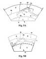
- FIG. 5Ais an enlarged view of a portion of the chuck as shown in FIG. 4A , in the area indicated by reference numeral 5 A;
- FIG. 5Bis an enlarged view of a portion of the chuck as shown in FIG. 4B , in the area indicated by reference numeral 5 B;
- FIG. 6is a partial, perspective view of the sleeve and nut retainer of the chuck shown in FIG. 1 ;
- FIGS. 7A and 7Bare enlarged, partial cross-sectional views of an alternate embodiment of a chuck in accordance with the present disclosure.
- a chuck 10 in accordance with the present disclosureincludes a body 14 , a nut 16 , a front sleeve 18 , a nose piece 20 , a dust cover 12 and a gripping mechanism including a plurality of jaws 22 .
- Body 14is generally cylindrical in shape and comprises a nose or forward section 24 and a tail or rearward section 26 .
- Nose section 24has a front face 28 transverse to the longitudinal center axis 30 of body 14 and a tapered surface 32 at its forward end.
- the nose sectiondefines an axial bore 34 that is dimensioned somewhat larger than the largest tool shank that the tool is designed to accommodate.
- a threaded bore 36is formed in tail section 26 and is of a standard size to mate with the drive shaft of a powered or hand driver (not shown).
- the bores 34 , 36may communicate at a central region 38 of body 14 . While a threaded bore 36 is illustrated, such bore could be replaced with a tapered bore of a standard size to mate with a tapered drive shaft.
- body 14may be formed integrally with the drive shaft.
- Body 14defines three passageways 40 to accommodate three jaws 22 .
- Each jawis separated from the adjacent jaw by an arc of approximately 120°.
- the axes of passageways 40 and jaws 22are angled with respect to the chuck center axis 30 such that each passageway axis travels through axial bore 34 and intersects axis 30 at a common point ahead of the chuck body.
- the jawsform a grip that moves radially toward and away from the chuck axis to grip a tool, and each jaw 22 has a tool engaging face 42 generally parallel to the axis of chuck body 14 .
- Threads 44formed on the opposite or outer surface of each jaw 22 , may be constructed in any suitable type and pitch.
- body 14includes a thrust ring 46 that, in a preferred embodiment, may be integral with the body. It should be understood, however, that thrust ring 46 and body 14 may be separate components. Thrust ring 46 includes a plurality of jaw guideways 48 formed around its circumference to permit retraction of jaws 22 therethrough and also includes a ledge portion 50 to receive a bearing assembly as described below.
- Body tail section 26includes a knurled surface 54 that receives dust cover rear sleeve 12 in a press fit. Dust cover 12 could also be retained by press fit without knurling, by use of a key or by crimping, staking, riveting, threading or any other suitable securing mechanism.
- the chuckmay be constructed with a single sleeve having no rear sleeve, for example, where the power driver to which the chuck is attached includes a spindle lock feature to enable actuation of the chuck by the single sleeve when the spindle is rotationally fixed by the spindle lock.
- Nut 16which in the preferred embodiment is a split nut, defines female threads 56 located on inner circumference of the nut and is received in a groove 57 formed in chuck body 14 proximate thrust ring member 46 . Threads 56 are configured to mate with jaw threads 44 . Nut 16 is positioned about the body in engagement with the jaw threads so that when the nut is rotated with respect to body 14 , the jaws will be advanced or retracted depending on the rotational direction of nut 16 . A bearing washer 70 and an annular bearing cage 72 are received between thrust ring 46 and nut 16 . Bearing cage 72 holds a plurality of balls 74 that permits the nut to rotate relative to the chuck body.
- a nut retainer 90includes a body portion 94 and a plurality of drive dogs 96 that depend axially outwardly from a front edge of body portion 94 .
- Drive dogs 96are configured to each receive a corresponding locking pawl 80 and interact with a corresponding recess 62 ( FIG. 6 ) defined by the inner surface of front sleeve 18 , as discussed in greater detail below.
- Body portion 94 of nut retainer 90is received about split nut 16 in a press-fit, thereby retaining nut 16 in groove 57 of the chuck body and non-rotatably fixed nut retainer 90 to nut 16 .
- nut retainer's body portion 94abuts an annular ledge 17 that depends radially outwardly from nut 16 , thereby ensuring nut retainer 90 is in the desired axial position with respect to first sleeve 18 and body 14 .
- outer sleeve 18may be knurled or may be provided with longitudinal ribs 77 or other protrusions to enable the operator to grip it securely.
- the circumferential surface of dust cover 12if employed, may be knurled or ribbed if desired.
- Nose piece 20is press fit to body nose section 24 and retains front sleeve 18 against forward axial movement. More specifically, as best seen in FIG. 2 , an annular ledge 19 depends radially inwardly from the inner surface of front sleeve 18 adjacent its front end. Annular ledge 19 is rotatably received in a gap found between the rear edge 21 of nose piece 20 and forwardly facing ledge 23 of body 14 .
- Nose piece 20may be coated with a non-ferrous metallic coating to prevent rust and to enhance its appearance.
- suitable coatingsinclude zinc or nickel, although it should be appreciated that any suitable coating could be utilized.
- Front sleeve 18 and dust cover 12may be molded or otherwise fabricated from a structural plastic such as polycarbonate, a filled polypropylene, for example a glass filled polypropylene, or a blend of structural plastic materials.
- a structural plasticsuch as polycarbonate, a filled polypropylene, for example a glass filled polypropylene, or a blend of structural plastic materials.
- Other composite materialssuch as, for example, graphite filled polymerics may also be suitable in certain environments.
- the materials for which the chuck of the present disclosure is fabricatedwill depend on the end use of the chuck, and the above materials are provided by way of example only.
- each drive dog 96 of nut retainer 90has a deflectable locking pawl 80 mounted thereon.
- Each locking pawl 80includes a proximal end, or mounting portion 81 , a distal end, or engagement portion 88 , and a central portion 86 extending therebetween.
- Engagement portion 88includes a biasing cam 88 b and a locking tip 88 a .
- Biasing cam 88 bis configured to slide along a corresponding camming surface 104 of front sleeve 18 and be received in either base 104 a or locking recess 106 thereof, dependent upon whether front sleeve 18 is in a first rotational position or second rotational position, respectively, with respect to nut 16 .
- Locking tip 88 a of each locking pawl 80is configured to selectively engage the annular array of locking teeth 84 , thereby preventing unintentional loosening of the chuck, as discussed in greater detail below.
- each drive dog 96 in the axial directionis greater than the length of the corresponding mounting portion 81 in the axial direction.
- a front portion 96 a of each drive dog 96extends outwardly beyond the mounting portion of the corresponding locking pawl 80 when the locking pawl is mounted thereto in a press-fit. It is only front portion 96 a of each drive dog 96 that is slidably received in the corresponding recess 62 of front sleeve 18 .
- Body 14also includes a ratchet in the form of an annular array of locking teeth 84 .
- the arrayis formed by a plurality of sawtooth shaped teeth 84 disposed about an outer circumferential surface of body 14 forward of annular groove 57 .
- each tooth 84has a first side with a slope approaching 90°, whereas the second side of each tooth 84 has a lesser slope.
- Each locking pawl 80is deflectable and the locking tip of each engagement portion 88 is generally disposed in alignment with the slope of the second sides of the teeth.
- each locking pawl 80includes a biasing cam 88 b whereas the inner surface of sleeve 18 defines a plurality of camming surfaces 104 , each one including a first recess, or base 104 a , and a second recess, or lock recess 106 , disposed at its opposing ends. More specifically, a camming surface 104 is present for each locking pawl 80 .
- each biasing cam 88 bis received either at a base 104 a of a corresponding cam surface 104 or its lock recess 106 .
- Base 104 a of each camming surface 104is the radially outermost portion of the camming surface and is where the biasing cam 88 b of the corresponding lock pawl 80 is received when the chuck is in the unlocked position ( FIG. 4A ), as discussed in greater detail below.
- FIG. 4Aillustrates the disposition of lock pawls 80 when front sleeve 18 is in a first of two positions with respect to nut 16
- FIG. 4Billustrates these components when front sleeve 18 is in a second position with respect to the nut.
- each drive dog 96is disposed against or adjacent a side 108 of recess 62 in which it is received when sleeve 18 is in the second, or locked, position with respect to the nut.
- each biasing cam 88 bis received in a corresponding lock recess 106 .
- each locking pawl 80is forced inwardly until its locking tip 88 a engages ratchet teeth 84 , meaning nut retainer 90 and, therefore, nut 16 can rotate only in closing direction 100 with respect to body 14 .
- each biasing cam 88 brides out of the respective lock recess 106 and along cam surface 104 until reaching its base 104 a , in the direction indicated by arrow 110 .
- Thisallows each deflectable locking pawl 80 to return to its normal, outwardly biased position, thereby disengaging locking tips 88 a of the locking pawls' engagement portions 88 from ratchet teeth 84 .
- nut 16is free to rotate with respect to chuck body 14 .
- Continued rotation of front sleeve 18 in opening direction 102subsequently causes the rotation of nut 16 in the opening direction, thereby causing each jaw 22 to be withdrawn in its corresponding passageway 40 into the chuck body.
- drive dogs 96 of nut retainer 90move within recesses 62 of front sleeve ( FIG. 6 ) so that each drive dog 96 is against or immediately adjacent to a side 110 of the corresponding recess.
- recesses 62 of front sleeve 18receive drive dogs 96 when the chuck is between fully opened and fully closed positions so that the drive dogs 96 are adjacent recess sides 110 .
- Locking pawls 80are disposed with respect to front sleeve 18 so that biasing cams 88 b are received by respective camming surface bases 104 a . That is, front sleeve 18 is in the first, unlocked position with respect to the nut. In this position, biasing cams 88 b and camming surface bases 104 a rotationally fix nut retainer 90 to front sleeve 18 .
- nut retainer 90Since nut retainer 90 is rotationally fixed to nut 16 by a press-fit, an operator rotating front sleeve 18 rotationally drives the nut through nut retainer 90 , thereby opening or closing the jaws.
- the operatorrotates the sleeve/nut retainer/nut in the closing direction (indicated by arrow 100 ) to the point that the jaws tighten onto a tool shank, the nut is urged rearward up the jaw threads, thereby pushing the nut against bearing elements 74 , bearing washer 70 , and thrust ring 46 .
- camming surfaces 104rotate relative to biasing cams 88 b in direction 110 so that the biasing cams leave their respective bases 104 a and ride up on the camming surfaces, thereby biasing engagement portions 88 of locking pawls 80 inwardly.
- locking tips 88 a of the pawlsengage ratchet teeth 84 of the annular array, as shown in FIGS. 4B and 5B .
- nut 16is rotationally locked to chuck body 14 , against rotation in opening direction 102 of the chuck. Since the rotation of the nut with respect to the body is necessary to open the chuck, this configuration of lock pawls 80 relative to ratchet teeth 84 resists inadvertent opening during use.
- each locking pawlis configured to exert force in the closing direction on nut 16 when engaging locking teeth 84 . More specifically, as best seen in FIGS. 5A and 5B , when front sleeve 18 is in the first, unlocked position with respect to nut 16 , biasing cam 88 b of each locking pawl 80 is received in a corresponding base 104 a , and distal end 88 of each locking pawl 80 is in an at-rest, unbiased position. In the at-rest position, the two “legs” of each engagement portion 88 define a first angle ( ⁇ 1 ). However, as front sleeve 18 is rotated to the second, locked position, each engagement portion 88 is biased radially inwardly until each locking tip 88 a engages locking teeth 84 , as previously noted.
- each engagement portion 88 awhen front sleeve reaches the second, locked position, the legs of each engagement portion 88 a define a second angle ( ⁇ 2 ), that is greater than the first angle defined by the legs of each engagement portion 88 when in the unbiased position.
- ⁇ 2the first angle defined by the legs of each engagement portion 88 when in the unbiased position.
- each engagement portion, and subsequently each locking pawl 80becomes elongated as compared to its non-compressed state. Because each locking pawl is non-rotatably fixed to nut 16 by way of nut retainer 90 , this elongation of the locking pawl necessarily means that an additional biasing force in the closing direction is exerted on nut 16 , thereby enhancing the overall amount of force that helps prevent the inadvertent opening, or loosening, of the chuck.
- Locking pawls 80 , and therefore nut 16may, however, still rotate with respect to locking teeth 84 , and therefore body 14 , in closing direction 100 of the chuck.
- the sleevedrives nut 16 through drive dogs 96 which are positioned against groove sides 108 . This continues to tighten the chuck and, as described above, produces a clicking sound to notify the operator that the chuck is in a fully tightened position.
- Front sleeve 18transfers this torque to nut retainer 90 at the engagement of biasing cams 88 b in lock recesses 106 . Because locking pawls 80 engage ratchet teeth 84 , which are rotationally fixed to the body, nut retainer 90 and nut 16 cannot rotate with the front sleeve. Thus, upon application of sufficient torque in the opening direction 102 , front sleeve 18 rotates with respect to the nut retainer and the nut, thereby moving biasing cams 88 b out of lock recesses 106 .
- front sleeve 18 in opening direction 102causes biasing cams 88 b to slide along their respective camming surface 104 and back into bases 104 a , thereby disengaging locking tips 88 a of respective locking pawls 88 from ratchet teeth 84 .
- drive dogs 96move from sides 108 to sides 110 of recesses 62 .
- the front sleevemoves to the first position with respect to the nut, as shown in FIG. 4A , and the nut retainer and nut are free to rotate with respect to the chuck body. Accordingly, further rotation of front sleeve 18 in the opening direction moves jaws 22 away from the chuck axis, thereby opening the chuck.
- FIGS. 7A and 7Ba chuck in accordance with an alternate embodiment of the present disclosure is shown.
- the chuckfunctions in substantially the same manner as the previously discussed first embodiment and, as such, a full description of the chuck's construction and operation is not required here. Similar elements between the two chucks received the same reference numerals, and only those elements that differ have been given different referencing numerals.
- the embodiment shown in FIGS. 7A and 7Bdiffers from the first embodiment in that lock recess 106 of the first embodiment has been replaced with a lock surface 106 a in the present embodiment.
- FIG. 7Aillustrates the disposition of lock pawls 80 when front sleeve 18 of the second embodiment is in a first of two positions with respect to nut 16
- FIG. 7Billustrates these components when front sleeve 18 is in a second position with respect to the nut.
- each drive dog 96is disposed against or adjacent a side 108 of a recess 62 in which it is received when sleeve 18 is in the second position with respect to the nut.
- each biasing cam 88 bis received adjacent a corresponding lock surface 106 a .
- engagement portion 88 of each locking pawlis forced inwardly until its locking tip 88 a engages locking teeth 84 , meaning nut retainer 90 and, therefore, nut 16 can rotate only in closing direction 100 with respect to body 14 .
- an innermost corner 107 of lock surface 106 aextends radially inwardly beyond biasing cam 88 b of the respective engagement portion 88 .
- biasing cam 88 bslides outwardly along lock surface 106 a until further movement along the surface is no longer possible.
- rotation of sleeve 18 in locking direction 100 ( FIG. 4A ) relative to the locking pawlsis limited by the abutment of drive dogs 96 against sides 108 of the corresponding recesses 62 .
- the embodiment illustrated in the figuresis provided by way of explanation only and that the present invention may be realized in any suitable form.
- the pawls and ratchetmay be formed in any suitable configuration.
- the embodiments disclosed hereininclude three locking pawls, alternate embodiments may include more than three locking pawls and as few as one.
- the present inventionmay be used in a variety of configurations whereby a bearing having a ratchet configuration is disposed between a sleeve, for example a nut or other suitable configuration, and the chuck body.
Landscapes
- Engineering & Computer Science (AREA)
- Mechanical Engineering (AREA)
- Gripping On Spindles (AREA)
Abstract
Description
Claims (18)
Priority Applications (1)
| Application Number | Priority Date | Filing Date | Title |
|---|---|---|---|
| US13/826,690US10556276B2 (en) | 2013-03-14 | 2013-03-14 | Locking chuck |
Applications Claiming Priority (1)
| Application Number | Priority Date | Filing Date | Title |
|---|---|---|---|
| US13/826,690US10556276B2 (en) | 2013-03-14 | 2013-03-14 | Locking chuck |
Publications (2)
| Publication Number | Publication Date |
|---|---|
| US20140265163A1 US20140265163A1 (en) | 2014-09-18 |
| US10556276B2true US10556276B2 (en) | 2020-02-11 |
Family
ID=51524097
Family Applications (1)
| Application Number | Title | Priority Date | Filing Date |
|---|---|---|---|
| US13/826,690Active2035-08-21US10556276B2 (en) | 2013-03-14 | 2013-03-14 | Locking chuck |
Country Status (1)
| Country | Link |
|---|---|
| US (1) | US10556276B2 (en) |
Families Citing this family (6)
| Publication number | Priority date | Publication date | Assignee | Title |
|---|---|---|---|---|
| US8616561B2 (en)* | 2012-04-10 | 2013-12-31 | Apex Brands, Inc. | Locking chuck |
| US10603722B2 (en) | 2014-10-10 | 2020-03-31 | Apex Brands, Inc. | Locking chuck |
| DE102015102241B4 (en)* | 2015-02-17 | 2024-10-02 | Röhm Gmbh | Drill chuck |
| WO2020000905A1 (en)* | 2018-06-28 | 2020-01-02 | 山东威达机械股份有限公司 | Drill chuck |
| KR102291030B1 (en)* | 2019-12-02 | 2021-08-20 | 계양전기 주식회사 | Chuck for power tool |
| US20210231230A1 (en)* | 2020-01-29 | 2021-07-29 | Stephen E. Finegan, Jr. | Universal stem shaft handle |
Citations (69)
| Publication number | Priority date | Publication date | Assignee | Title |
|---|---|---|---|---|
| US573189A (en) | 1896-12-15 | Ernest ii | ||
| US1410080A (en) | 1921-12-01 | 1922-03-21 | Schwahlen Josef | Chuck |
| US2684856A (en) | 1950-03-18 | 1954-07-27 | Jacobs Mfg Co | Apparatus for tightening chucks of power drills |
| US3237955A (en) | 1964-01-03 | 1966-03-01 | Jacobs Mfg Co | Keyless chuck |
| US3325166A (en) | 1964-01-03 | 1967-06-13 | Jacobs Mfg Co | Chuck jaw guide means |
| US3506277A (en) | 1967-03-03 | 1970-04-14 | Zimmer Mfg Co | Keyless chuck adapter |
| US3545776A (en) | 1968-06-18 | 1970-12-08 | Jacobs Mfg Co | Combined chuck spindle and chuck locking collar |
| US3970323A (en) | 1973-08-17 | 1976-07-20 | Metabowerke Kg Closs, Rauch, & Schnitzler | Chuck for drill |
| US4277074A (en) | 1979-11-26 | 1981-07-07 | Harry Kilberis | Keyless chuck |
| US4317578A (en) | 1979-11-07 | 1982-03-02 | Welch Thomas R | Keyless chucking system |
| US4358230A (en) | 1980-04-04 | 1982-11-09 | Rohlin Robert W | Chuck operating device for hand drill |
| US4395170A (en) | 1980-08-18 | 1983-07-26 | The Singer Company | Drill, drill chuck, and methods of chucking and unchucking |
| US4491445A (en) | 1981-08-17 | 1985-01-01 | Hilti Aktiengesellschaft | Tool holder for hammer drills |
| US4498682A (en) | 1982-11-17 | 1985-02-12 | The Singer Company | Free floating actuating sleeve for keyless chuck |
| US4526497A (en) | 1982-03-15 | 1985-07-02 | Hatfield Jim J | Automatic jaw control for reversible power tool |
| US4536113A (en) | 1982-03-15 | 1985-08-20 | Hatfield Jim J | Automatic jaw control for reversible power tool |
| US4621820A (en) | 1984-04-11 | 1986-11-11 | Roehm Guenter H | Percussion drilling apparatus |
| US4627628A (en) | 1984-02-24 | 1986-12-09 | Roehm Guenter H | Hammer drill chuck |
| US4627627A (en) | 1984-06-15 | 1986-12-09 | Roehm Guenter H | Percussion or impact drill chuck |
| US4627626A (en) | 1984-05-08 | 1986-12-09 | Roehm Guenter H | Chuck for a hammer or rotary impact drill |
| US4655464A (en) | 1984-05-21 | 1987-04-07 | Hilti Aktiengesellschaft | Drill chuck for a hand-held device |
| US4660841A (en) | 1985-01-14 | 1987-04-28 | Chouinard Michael J | Hand tightenable device for holding a cutting implement |
| US4669932A (en) | 1985-05-24 | 1987-06-02 | Wayne Hartley | Keyless tool chuck |
| US4682918A (en) | 1984-04-16 | 1987-07-28 | Milwaukee Electric Tool Corporation | Keyless impacting chuck |
| US4695066A (en) | 1984-12-15 | 1987-09-22 | Roehm Guenter H | Chip-shedding hammer-drill chuck |
| US4695065A (en) | 1986-01-21 | 1987-09-22 | Matsushita Electric Works, Ltd. | Keyless chuck for rotary tool |
| US4700956A (en) | 1984-12-15 | 1987-10-20 | Roehm Guenter H | Lockable and self-tightening hammer-drill chuck |
| US4703942A (en) | 1985-05-08 | 1987-11-03 | Roehm Guenter H | Hammer drill |
| US4703941A (en) | 1985-03-14 | 1987-11-03 | Roehm Guenter H | Hammer drill chuck assembly |
| US4773657A (en) | 1984-06-15 | 1988-09-27 | Roehm Guenter H | Drill apparatus |
| US4824298A (en) | 1986-10-23 | 1989-04-25 | Hilti Aktiengesellschaft | Hand-held tool with detachable tool bit chuck |
| US4840387A (en) | 1988-01-20 | 1989-06-20 | The Jacobs Manufacturing Company | Self-actuating keyless chuck |
| US4844482A (en) | 1986-11-21 | 1989-07-04 | Roehm Guenter H | Drill chuck |
| US4848779A (en) | 1987-04-02 | 1989-07-18 | Black & Decker Inc. | Keyless chuck |
| US4930793A (en) | 1987-11-09 | 1990-06-05 | Emu-Esu Industrial Co., Ltd. | Keyless chuck |
| US4951955A (en) | 1987-10-16 | 1990-08-28 | Sakamaki Mfg. Co., Ltd. | Chuck for tools |
| US4958840A (en) | 1988-05-27 | 1990-09-25 | Milwaukee Electric Tool Corporation | Self disengaging keyless chuck |
| US4968191A (en) | 1988-05-27 | 1990-11-06 | Milwaukee Electric Tool Corporation | Chuck mount |
| US5009439A (en) | 1987-07-21 | 1991-04-23 | Sakamaki Mfg. Co., Ltd. | Chuck for tools |
| US5031925A (en) | 1988-03-28 | 1991-07-16 | Matsushita Electric Works, Ltd. | Keyless chuck for rotary tool |
| US5044643A (en) | 1989-06-16 | 1991-09-03 | Daijiro Nakamura | Tool chuck |
| US5125673A (en) | 1989-12-11 | 1992-06-30 | Huff Robert O | Non-impact keyless chuck |
| US5145194A (en) | 1991-06-21 | 1992-09-08 | Jacobs Chuck Technology Corporation | Impact tool chuck |
| US5145193A (en) | 1990-07-21 | 1992-09-08 | Roehm Guenter H | Lockable drill chuck |
| US5145192A (en) | 1990-07-21 | 1992-09-08 | Roehm Guenter H | Lockable drill chuck |
| US5174588A (en) | 1990-02-23 | 1992-12-29 | Robert Bosch Gmbh | Automatically locking chuck for drill or the like |
| US5183274A (en) | 1991-06-13 | 1993-02-02 | Yukiwa Seiko Kabushikikaisya | Chuck for tools |
| US5195760A (en) | 1990-06-12 | 1993-03-23 | Black & Decker Inc. | Keyless chuck |
| US5232230A (en) | 1992-09-28 | 1993-08-03 | Lin Pi Chu | Chuck assembly for a drilling apparatus |
| US5234223A (en) | 1987-07-21 | 1993-08-10 | Sakamaki Mfg. Co., Ltd. | Chuck for tools |
| US5348317A (en) | 1993-08-13 | 1994-09-20 | Jacobs Chuck Technology Corporation | Chuck |
| US5375857A (en) | 1992-11-16 | 1994-12-27 | Rohm; Guenter H. | Keyless lockable hammer-drill chuck |
| US5375858A (en) | 1992-11-16 | 1994-12-27 | Roehm; Guenter H. | Lockable self-tightening hammer-drill chuck |
| US5458345A (en) | 1993-03-26 | 1995-10-17 | Etablissements Amoyt S.A. | Tool-holder chuck for equipping a rotating machine, such as a drill |
| US5741016A (en) | 1996-10-02 | 1998-04-21 | Power Tool Holders Incorporated | Chuck |
| US5765839A (en)* | 1994-10-31 | 1998-06-16 | Roehm; Guenter Horst | Hammer-drill chuck |
| US5829761A (en) | 1996-01-17 | 1998-11-03 | Roehm; Guenter Horst | Drill chuck |
| US5957469A (en) | 1996-09-25 | 1999-09-28 | Power Tool Holders, Inc. | Spring chuck |
| US6341783B1 (en) | 1999-02-20 | 2002-01-29 | Rohm Gmbh | Drill chuck |
| US6390481B1 (en) | 2000-03-10 | 2002-05-21 | Power Tool Holders Incorporated | Locking chuck |
| US20020089127A1 (en)* | 2001-01-11 | 2002-07-11 | Rohm Gmbh | Lockable hammer-drill chuck |
| US20030042692A1 (en)* | 2001-08-30 | 2003-03-06 | Yukiwa Seiko Kabushiki Kaisha | Chuck device |
| US20030071425A1 (en)* | 2001-10-11 | 2003-04-17 | Yuan-Ho Lin | Anti-slip type electric drill chuck |
| US20050087937A1 (en)* | 2003-10-22 | 2005-04-28 | Wenhua Zhou | Lock type manually tightened chuck |
| US20050258605A1 (en)* | 2002-11-25 | 2005-11-24 | Xingda Tan | Self-locking drill chuck |
| US20060273529A1 (en)* | 2005-05-29 | 2006-12-07 | Shandong Weida Machinery Co., Ltd. | Clamping structure for a handled tool |
| US20060279048A1 (en)* | 2005-06-09 | 2006-12-14 | Bach Gong | Drill chuck |
| US7497444B2 (en)* | 2004-04-20 | 2009-03-03 | Yukiwa Seiko Kabushiki Kaisha | Chuck device |
| US20100127464A1 (en)* | 2006-12-23 | 2010-05-27 | Hans-Dieter Mack | Drill Chuck |
- 2013
- 2013-03-14USUS13/826,690patent/US10556276B2/enactiveActive
Patent Citations (70)
| Publication number | Priority date | Publication date | Assignee | Title |
|---|---|---|---|---|
| US573189A (en) | 1896-12-15 | Ernest ii | ||
| US1410080A (en) | 1921-12-01 | 1922-03-21 | Schwahlen Josef | Chuck |
| US2684856A (en) | 1950-03-18 | 1954-07-27 | Jacobs Mfg Co | Apparatus for tightening chucks of power drills |
| US3237955A (en) | 1964-01-03 | 1966-03-01 | Jacobs Mfg Co | Keyless chuck |
| US3325166A (en) | 1964-01-03 | 1967-06-13 | Jacobs Mfg Co | Chuck jaw guide means |
| US3506277A (en) | 1967-03-03 | 1970-04-14 | Zimmer Mfg Co | Keyless chuck adapter |
| US3545776A (en) | 1968-06-18 | 1970-12-08 | Jacobs Mfg Co | Combined chuck spindle and chuck locking collar |
| US3970323A (en) | 1973-08-17 | 1976-07-20 | Metabowerke Kg Closs, Rauch, & Schnitzler | Chuck for drill |
| US4317578A (en) | 1979-11-07 | 1982-03-02 | Welch Thomas R | Keyless chucking system |
| US4277074A (en) | 1979-11-26 | 1981-07-07 | Harry Kilberis | Keyless chuck |
| US4358230A (en) | 1980-04-04 | 1982-11-09 | Rohlin Robert W | Chuck operating device for hand drill |
| US4395170A (en) | 1980-08-18 | 1983-07-26 | The Singer Company | Drill, drill chuck, and methods of chucking and unchucking |
| US4491445A (en) | 1981-08-17 | 1985-01-01 | Hilti Aktiengesellschaft | Tool holder for hammer drills |
| US4526497A (en) | 1982-03-15 | 1985-07-02 | Hatfield Jim J | Automatic jaw control for reversible power tool |
| US4536113A (en) | 1982-03-15 | 1985-08-20 | Hatfield Jim J | Automatic jaw control for reversible power tool |
| US4498682A (en) | 1982-11-17 | 1985-02-12 | The Singer Company | Free floating actuating sleeve for keyless chuck |
| US4627628A (en) | 1984-02-24 | 1986-12-09 | Roehm Guenter H | Hammer drill chuck |
| US4621820A (en) | 1984-04-11 | 1986-11-11 | Roehm Guenter H | Percussion drilling apparatus |
| US4682918A (en) | 1984-04-16 | 1987-07-28 | Milwaukee Electric Tool Corporation | Keyless impacting chuck |
| US4627626A (en) | 1984-05-08 | 1986-12-09 | Roehm Guenter H | Chuck for a hammer or rotary impact drill |
| US4655464A (en) | 1984-05-21 | 1987-04-07 | Hilti Aktiengesellschaft | Drill chuck for a hand-held device |
| US4627627A (en) | 1984-06-15 | 1986-12-09 | Roehm Guenter H | Percussion or impact drill chuck |
| US4773657A (en) | 1984-06-15 | 1988-09-27 | Roehm Guenter H | Drill apparatus |
| US4695066A (en) | 1984-12-15 | 1987-09-22 | Roehm Guenter H | Chip-shedding hammer-drill chuck |
| US4700956A (en) | 1984-12-15 | 1987-10-20 | Roehm Guenter H | Lockable and self-tightening hammer-drill chuck |
| US4660841A (en) | 1985-01-14 | 1987-04-28 | Chouinard Michael J | Hand tightenable device for holding a cutting implement |
| US4703941A (en) | 1985-03-14 | 1987-11-03 | Roehm Guenter H | Hammer drill chuck assembly |
| US4703942A (en) | 1985-05-08 | 1987-11-03 | Roehm Guenter H | Hammer drill |
| US4669932A (en) | 1985-05-24 | 1987-06-02 | Wayne Hartley | Keyless tool chuck |
| US4695065A (en) | 1986-01-21 | 1987-09-22 | Matsushita Electric Works, Ltd. | Keyless chuck for rotary tool |
| US4824298A (en) | 1986-10-23 | 1989-04-25 | Hilti Aktiengesellschaft | Hand-held tool with detachable tool bit chuck |
| US4844482A (en) | 1986-11-21 | 1989-07-04 | Roehm Guenter H | Drill chuck |
| US4848779A (en) | 1987-04-02 | 1989-07-18 | Black & Decker Inc. | Keyless chuck |
| US5234223A (en) | 1987-07-21 | 1993-08-10 | Sakamaki Mfg. Co., Ltd. | Chuck for tools |
| US5009439A (en) | 1987-07-21 | 1991-04-23 | Sakamaki Mfg. Co., Ltd. | Chuck for tools |
| US4951955A (en) | 1987-10-16 | 1990-08-28 | Sakamaki Mfg. Co., Ltd. | Chuck for tools |
| US4930793A (en) | 1987-11-09 | 1990-06-05 | Emu-Esu Industrial Co., Ltd. | Keyless chuck |
| US4840387A (en) | 1988-01-20 | 1989-06-20 | The Jacobs Manufacturing Company | Self-actuating keyless chuck |
| US5031925A (en) | 1988-03-28 | 1991-07-16 | Matsushita Electric Works, Ltd. | Keyless chuck for rotary tool |
| US4958840A (en) | 1988-05-27 | 1990-09-25 | Milwaukee Electric Tool Corporation | Self disengaging keyless chuck |
| US4968191A (en) | 1988-05-27 | 1990-11-06 | Milwaukee Electric Tool Corporation | Chuck mount |
| US5044643A (en) | 1989-06-16 | 1991-09-03 | Daijiro Nakamura | Tool chuck |
| US5125673A (en) | 1989-12-11 | 1992-06-30 | Huff Robert O | Non-impact keyless chuck |
| US5174588A (en) | 1990-02-23 | 1992-12-29 | Robert Bosch Gmbh | Automatically locking chuck for drill or the like |
| US5195760A (en) | 1990-06-12 | 1993-03-23 | Black & Decker Inc. | Keyless chuck |
| US5145192A (en) | 1990-07-21 | 1992-09-08 | Roehm Guenter H | Lockable drill chuck |
| US5145193A (en) | 1990-07-21 | 1992-09-08 | Roehm Guenter H | Lockable drill chuck |
| US5183274A (en) | 1991-06-13 | 1993-02-02 | Yukiwa Seiko Kabushikikaisya | Chuck for tools |
| US5145194A (en) | 1991-06-21 | 1992-09-08 | Jacobs Chuck Technology Corporation | Impact tool chuck |
| US5232230A (en) | 1992-09-28 | 1993-08-03 | Lin Pi Chu | Chuck assembly for a drilling apparatus |
| US5375858A (en) | 1992-11-16 | 1994-12-27 | Roehm; Guenter H. | Lockable self-tightening hammer-drill chuck |
| US5375857A (en) | 1992-11-16 | 1994-12-27 | Rohm; Guenter H. | Keyless lockable hammer-drill chuck |
| US5458345A (en) | 1993-03-26 | 1995-10-17 | Etablissements Amoyt S.A. | Tool-holder chuck for equipping a rotating machine, such as a drill |
| US5348317A (en) | 1993-08-13 | 1994-09-20 | Jacobs Chuck Technology Corporation | Chuck |
| US5765839A (en)* | 1994-10-31 | 1998-06-16 | Roehm; Guenter Horst | Hammer-drill chuck |
| US5829761A (en) | 1996-01-17 | 1998-11-03 | Roehm; Guenter Horst | Drill chuck |
| US5957469A (en) | 1996-09-25 | 1999-09-28 | Power Tool Holders, Inc. | Spring chuck |
| US5741016A (en) | 1996-10-02 | 1998-04-21 | Power Tool Holders Incorporated | Chuck |
| US6341783B1 (en) | 1999-02-20 | 2002-01-29 | Rohm Gmbh | Drill chuck |
| US6390481B1 (en) | 2000-03-10 | 2002-05-21 | Power Tool Holders Incorporated | Locking chuck |
| US20020089127A1 (en)* | 2001-01-11 | 2002-07-11 | Rohm Gmbh | Lockable hammer-drill chuck |
| US20030042692A1 (en)* | 2001-08-30 | 2003-03-06 | Yukiwa Seiko Kabushiki Kaisha | Chuck device |
| US6659474B2 (en)* | 2001-08-30 | 2003-12-09 | Yukiwa Seiko Kabushiki Kaisha | Chuck device |
| US20030071425A1 (en)* | 2001-10-11 | 2003-04-17 | Yuan-Ho Lin | Anti-slip type electric drill chuck |
| US20050258605A1 (en)* | 2002-11-25 | 2005-11-24 | Xingda Tan | Self-locking drill chuck |
| US20050087937A1 (en)* | 2003-10-22 | 2005-04-28 | Wenhua Zhou | Lock type manually tightened chuck |
| US7497444B2 (en)* | 2004-04-20 | 2009-03-03 | Yukiwa Seiko Kabushiki Kaisha | Chuck device |
| US20060273529A1 (en)* | 2005-05-29 | 2006-12-07 | Shandong Weida Machinery Co., Ltd. | Clamping structure for a handled tool |
| US20060279048A1 (en)* | 2005-06-09 | 2006-12-14 | Bach Gong | Drill chuck |
| US20100127464A1 (en)* | 2006-12-23 | 2010-05-27 | Hans-Dieter Mack | Drill Chuck |
Also Published As
| Publication number | Publication date |
|---|---|
| US20140265163A1 (en) | 2014-09-18 |
Similar Documents
| Publication | Publication Date | Title |
|---|---|---|
| US6390481B1 (en) | Locking chuck | |
| US7527273B2 (en) | Locking chuck | |
| US9358617B2 (en) | Chuck | |
| US9352397B2 (en) | Locking chuck | |
| US6260856B1 (en) | Locking chuck | |
| US7845651B2 (en) | Locking chuck | |
| US8191902B2 (en) | Drill chuck | |
| US7900937B2 (en) | Locking chuck | |
| US6572310B2 (en) | Self-cleaning drill chuck | |
| US9662713B2 (en) | Locking chuck jaws | |
| US10556276B2 (en) | Locking chuck | |
| US20210370414A1 (en) | Chuck with Slip Protection | |
| US20140077463A1 (en) | Locking chuck | |
| GB2389809A (en) | Locking chuck |
Legal Events
| Date | Code | Title | Description |
|---|---|---|---|
| AS | Assignment | Owner name:APEX BRANDS, INC., MARYLAND Free format text:ASSIGNMENT OF ASSIGNORS INTEREST;ASSIGNOR:MASON, NEIL;REEL/FRAME:030276/0178 Effective date:20130423 | |
| STPP | Information on status: patent application and granting procedure in general | Free format text:NON FINAL ACTION MAILED | |
| STPP | Information on status: patent application and granting procedure in general | Free format text:RESPONSE TO NON-FINAL OFFICE ACTION ENTERED AND FORWARDED TO EXAMINER | |
| STPP | Information on status: patent application and granting procedure in general | Free format text:FINAL REJECTION MAILED | |
| STPP | Information on status: patent application and granting procedure in general | Free format text:RESPONSE AFTER FINAL ACTION FORWARDED TO EXAMINER | |
| STPP | Information on status: patent application and granting procedure in general | Free format text:NOTICE OF ALLOWANCE MAILED -- APPLICATION RECEIVED IN OFFICE OF PUBLICATIONS | |
| STPP | Information on status: patent application and granting procedure in general | Free format text:PUBLICATIONS -- ISSUE FEE PAYMENT VERIFIED | |
| STCF | Information on status: patent grant | Free format text:PATENTED CASE | |
| AS | Assignment | Owner name:BARCLAYS BANK PLC, AS COLLATERAL AGENT, NEW YORK Free format text:FIRST LIEN GRANT OF SECURITY INTEREST IN PATENTS;ASSIGNOR:APEX BRANDS, INC.;REEL/FRAME:058991/0556 Effective date:20220208 Owner name:BARCLAYS BANK PLC, AS COLLATERAL AGENT, NEW YORK Free format text:SECOND LIEN GRANT OF SECURITY INTEREST IN PATENTS;ASSIGNOR:APEX BRANDS, INC.;REEL/FRAME:058991/0442 Effective date:20220208 | |
| MAFP | Maintenance fee payment | Free format text:PAYMENT OF MAINTENANCE FEE, 4TH YEAR, LARGE ENTITY (ORIGINAL EVENT CODE: M1551); ENTITY STATUS OF PATENT OWNER: LARGE ENTITY Year of fee payment:4 | |
| AS | Assignment | Owner name:ALTER DOMUS (US) LLC, ILLINOIS Free format text:SUPER PRIORITY GRANT OF SECURITY INTEREST IN PATENT;ASSIGNOR:APEX BRANDS, INC.;REEL/FRAME:066631/0791 Effective date:20240220 | |
| AS | Assignment | Owner name:BARCLAYS BANK PLC, AS COLLATERAL AGENT, NEW YORK Free format text:SUPER PRIORITY GRANT OF SECURITY INTEREST IN PATENTS;ASSIGNORS:APEX BRANDS, INC.;APEX TOOL GROUP, LLC;REEL/FRAME:067310/0054 Effective date:20240502 | |
| AS | Assignment | Owner name:ALTER DOMUS (US) LLC, ILLINOIS Free format text:CORRECTIVE ASSIGNMENT TO CORRECT THE THE APPLICATION NO. 16/672703 PAT. NO. 11191173 WAS INCORRCTLY INCLUDED AND SHOULD BE REMOVED FROM THE RECORDS. PREVIOUSLY RECORDED AT REEL: 66631 FRAME: 791. ASSIGNOR(S) HEREBY CONFIRMS THE SUPER PRIORITY GRANT OF SECURITY INTEREST IN PATENT;ASSIGNOR:APEX BRANDS, INC.;REEL/FRAME:067884/0469 Effective date:20240220 | |
| AS | Assignment | Owner name:BARCLAYS BANK PLC, AS COLLATERAL AGENT, NEW YORK Free format text:CORRECTIVE ASSIGNMENT TO CORRECT THE APPLICATION NO. 16/672703 PAT NO. 11191173 WHICH WAS INCORRECTLY INCLUDED AND SHOULD BE REMOVED FROM THE RECORDS PREVIOUSLY RECORDED ON REEL 67310 FRAME 54. ASSIGNOR(S) HEREBY CONFIRMS THE SUPER PRIORITY GRANT OF SECURITY INTEREST IN PATENTS;ASSIGNORS:APEX BRANDS, INC.;APEX TOOL GROUP, LLC;REEL/FRAME:068791/0141 Effective date:20240502 Owner name:BARCLAYS BANK PLC, AS COLLATERAL AGENT, NEW YORK Free format text:CORRECTIVE ASSIGNMENT TO CORRECT THE CORRECT THE APPLICATION NO. 16/672703 PAT NO. 11191173 WHICH WAS INCORRECTLY INCLUDED AND SHOULD BE REMOVED FROM THE RECORDS PREVIOUSLY RECORDED AT REEL: 58991 FRAME: 442. ASSIGNOR(S) HEREBY CONFIRMS THE ASSIGNMENT;ASSIGNOR:APEX BRANDS, INC.;REEL/FRAME:068753/0687 Effective date:20220208 Owner name:BARCLAYS BANK PLC, AS COLLATERAL AGENT, NEW YORK Free format text:CORRECTIVE ASSIGNMENT TO CORRECT THE CORRECT THE APPLICATION NO. 16/672703 PAT NO. 11191173 WHICH WAS INCORRECTLY INCLUDED AND SHOULD BE REMOVED FROM THE RECORDS PREVIOUSLY RECORDED AT REEL: 58991 FRAME: 556. ASSIGNOR(S) HEREBY CONFIRMS THE FIRST LIEN GRANT OF SECURITY INTEREST IN PATENTS;ASSIGNOR:APEX BRANDS, INC.;REEL/FRAME:068769/0309 Effective date:20220208 |