US10555778B2 - Image-based branch detection and mapping for navigation - Google Patents
Image-based branch detection and mapping for navigationDownload PDFInfo
- Publication number
- US10555778B2 US10555778B2US15/783,903US201715783903AUS10555778B2US 10555778 B2US10555778 B2US 10555778B2US 201715783903 AUS201715783903 AUS 201715783903AUS 10555778 B2US10555778 B2US 10555778B2
- Authority
- US
- United States
- Prior art keywords
- instrument
- openings
- image
- feature
- detected
- Prior art date
- Legal status (The legal status is an assumption and is not a legal conclusion. Google has not performed a legal analysis and makes no representation as to the accuracy of the status listed.)
- Active
Links
Images


Classifications
- A—HUMAN NECESSITIES
- A61—MEDICAL OR VETERINARY SCIENCE; HYGIENE
- A61B—DIAGNOSIS; SURGERY; IDENTIFICATION
- A61B34/00—Computer-aided surgery; Manipulators or robots specially adapted for use in surgery
- A61B34/20—Surgical navigation systems; Devices for tracking or guiding surgical instruments, e.g. for frameless stereotaxis
- A—HUMAN NECESSITIES
- A61—MEDICAL OR VETERINARY SCIENCE; HYGIENE
- A61B—DIAGNOSIS; SURGERY; IDENTIFICATION
- A61B1/00—Instruments for performing medical examinations of the interior of cavities or tubes of the body by visual or photographical inspection, e.g. endoscopes; Illuminating arrangements therefor
- A61B1/00002—Operational features of endoscopes
- A61B1/00004—Operational features of endoscopes characterised by electronic signal processing
- A61B1/00009—Operational features of endoscopes characterised by electronic signal processing of image signals during a use of endoscope
- A61B1/000094—Operational features of endoscopes characterised by electronic signal processing of image signals during a use of endoscope extracting biological structures
- A—HUMAN NECESSITIES
- A61—MEDICAL OR VETERINARY SCIENCE; HYGIENE
- A61B—DIAGNOSIS; SURGERY; IDENTIFICATION
- A61B1/00—Instruments for performing medical examinations of the interior of cavities or tubes of the body by visual or photographical inspection, e.g. endoscopes; Illuminating arrangements therefor
- A61B1/00002—Operational features of endoscopes
- A61B1/0002—Operational features of endoscopes provided with data storages
- A—HUMAN NECESSITIES
- A61—MEDICAL OR VETERINARY SCIENCE; HYGIENE
- A61B—DIAGNOSIS; SURGERY; IDENTIFICATION
- A61B1/00—Instruments for performing medical examinations of the interior of cavities or tubes of the body by visual or photographical inspection, e.g. endoscopes; Illuminating arrangements therefor
- A61B1/00147—Holding or positioning arrangements
- A61B1/00149—Holding or positioning arrangements using articulated arms
- A—HUMAN NECESSITIES
- A61—MEDICAL OR VETERINARY SCIENCE; HYGIENE
- A61B—DIAGNOSIS; SURGERY; IDENTIFICATION
- A61B1/00—Instruments for performing medical examinations of the interior of cavities or tubes of the body by visual or photographical inspection, e.g. endoscopes; Illuminating arrangements therefor
- A61B1/04—Instruments for performing medical examinations of the interior of cavities or tubes of the body by visual or photographical inspection, e.g. endoscopes; Illuminating arrangements therefor combined with photographic or television appliances
- A61B1/05—Instruments for performing medical examinations of the interior of cavities or tubes of the body by visual or photographical inspection, e.g. endoscopes; Illuminating arrangements therefor combined with photographic or television appliances characterised by the image sensor, e.g. camera, being in the distal end portion
- A—HUMAN NECESSITIES
- A61—MEDICAL OR VETERINARY SCIENCE; HYGIENE
- A61B—DIAGNOSIS; SURGERY; IDENTIFICATION
- A61B1/00—Instruments for performing medical examinations of the interior of cavities or tubes of the body by visual or photographical inspection, e.g. endoscopes; Illuminating arrangements therefor
- A61B1/267—Instruments for performing medical examinations of the interior of cavities or tubes of the body by visual or photographical inspection, e.g. endoscopes; Illuminating arrangements therefor for the respiratory tract, e.g. laryngoscopes, bronchoscopes
- A61B1/2676—Bronchoscopes
- A—HUMAN NECESSITIES
- A61—MEDICAL OR VETERINARY SCIENCE; HYGIENE
- A61B—DIAGNOSIS; SURGERY; IDENTIFICATION
- A61B1/00—Instruments for performing medical examinations of the interior of cavities or tubes of the body by visual or photographical inspection, e.g. endoscopes; Illuminating arrangements therefor
- A61B1/273—Instruments for performing medical examinations of the interior of cavities or tubes of the body by visual or photographical inspection, e.g. endoscopes; Illuminating arrangements therefor for the upper alimentary canal, e.g. oesophagoscopes, gastroscopes
- A61B1/2736—Gastroscopes
- A—HUMAN NECESSITIES
- A61—MEDICAL OR VETERINARY SCIENCE; HYGIENE
- A61B—DIAGNOSIS; SURGERY; IDENTIFICATION
- A61B1/00—Instruments for performing medical examinations of the interior of cavities or tubes of the body by visual or photographical inspection, e.g. endoscopes; Illuminating arrangements therefor
- A61B1/307—Instruments for performing medical examinations of the interior of cavities or tubes of the body by visual or photographical inspection, e.g. endoscopes; Illuminating arrangements therefor for the urinary organs, e.g. urethroscopes, cystoscopes
- A—HUMAN NECESSITIES
- A61—MEDICAL OR VETERINARY SCIENCE; HYGIENE
- A61B—DIAGNOSIS; SURGERY; IDENTIFICATION
- A61B1/00—Instruments for performing medical examinations of the interior of cavities or tubes of the body by visual or photographical inspection, e.g. endoscopes; Illuminating arrangements therefor
- A61B1/313—Instruments for performing medical examinations of the interior of cavities or tubes of the body by visual or photographical inspection, e.g. endoscopes; Illuminating arrangements therefor for introducing through surgical openings, e.g. laparoscopes
- A61B1/3132—Instruments for performing medical examinations of the interior of cavities or tubes of the body by visual or photographical inspection, e.g. endoscopes; Illuminating arrangements therefor for introducing through surgical openings, e.g. laparoscopes for laparoscopy
- A—HUMAN NECESSITIES
- A61—MEDICAL OR VETERINARY SCIENCE; HYGIENE
- A61B—DIAGNOSIS; SURGERY; IDENTIFICATION
- A61B34/00—Computer-aided surgery; Manipulators or robots specially adapted for use in surgery
- A61B34/10—Computer-aided planning, simulation or modelling of surgical operations
- A—HUMAN NECESSITIES
- A61—MEDICAL OR VETERINARY SCIENCE; HYGIENE
- A61B—DIAGNOSIS; SURGERY; IDENTIFICATION
- A61B34/00—Computer-aided surgery; Manipulators or robots specially adapted for use in surgery
- A61B34/25—User interfaces for surgical systems
- A—HUMAN NECESSITIES
- A61—MEDICAL OR VETERINARY SCIENCE; HYGIENE
- A61B—DIAGNOSIS; SURGERY; IDENTIFICATION
- A61B34/00—Computer-aided surgery; Manipulators or robots specially adapted for use in surgery
- A61B34/30—Surgical robots
- A—HUMAN NECESSITIES
- A61—MEDICAL OR VETERINARY SCIENCE; HYGIENE
- A61B—DIAGNOSIS; SURGERY; IDENTIFICATION
- A61B46/00—Surgical drapes
- A61B46/10—Surgical drapes specially adapted for instruments, e.g. microscopes
- A—HUMAN NECESSITIES
- A61—MEDICAL OR VETERINARY SCIENCE; HYGIENE
- A61B—DIAGNOSIS; SURGERY; IDENTIFICATION
- A61B50/00—Containers, covers, furniture or holders specially adapted for surgical or diagnostic appliances or instruments, e.g. sterile covers
- A61B50/10—Furniture specially adapted for surgical or diagnostic appliances or instruments
- A61B50/13—Trolleys, e.g. carts
- A—HUMAN NECESSITIES
- A61—MEDICAL OR VETERINARY SCIENCE; HYGIENE
- A61B—DIAGNOSIS; SURGERY; IDENTIFICATION
- A61B90/00—Instruments, implements or accessories specially adapted for surgery or diagnosis and not covered by any of the groups A61B1/00 - A61B50/00, e.g. for luxation treatment or for protecting wound edges
- A61B90/36—Image-producing devices or illumination devices not otherwise provided for
- A61B90/361—Image-producing devices, e.g. surgical cameras
- A—HUMAN NECESSITIES
- A61—MEDICAL OR VETERINARY SCIENCE; HYGIENE
- A61B—DIAGNOSIS; SURGERY; IDENTIFICATION
- A61B90/00—Instruments, implements or accessories specially adapted for surgery or diagnosis and not covered by any of the groups A61B1/00 - A61B50/00, e.g. for luxation treatment or for protecting wound edges
- A61B90/36—Image-producing devices or illumination devices not otherwise provided for
- A61B90/37—Surgical systems with images on a monitor during operation
- A—HUMAN NECESSITIES
- A61—MEDICAL OR VETERINARY SCIENCE; HYGIENE
- A61G—TRANSPORT, PERSONAL CONVEYANCES, OR ACCOMMODATION SPECIALLY ADAPTED FOR PATIENTS OR DISABLED PERSONS; OPERATING TABLES OR CHAIRS; CHAIRS FOR DENTISTRY; FUNERAL DEVICES
- A61G13/00—Operating tables; Auxiliary appliances therefor
- A61G13/02—Adjustable operating tables; Controls therefor
- A61G13/04—Adjustable operating tables; Controls therefor tiltable around transverse or longitudinal axis
- A—HUMAN NECESSITIES
- A61—MEDICAL OR VETERINARY SCIENCE; HYGIENE
- A61G—TRANSPORT, PERSONAL CONVEYANCES, OR ACCOMMODATION SPECIALLY ADAPTED FOR PATIENTS OR DISABLED PERSONS; OPERATING TABLES OR CHAIRS; CHAIRS FOR DENTISTRY; FUNERAL DEVICES
- A61G13/00—Operating tables; Auxiliary appliances therefor
- A61G13/02—Adjustable operating tables; Controls therefor
- A61G13/08—Adjustable operating tables; Controls therefor the table being divided into different adjustable sections
- A—HUMAN NECESSITIES
- A61—MEDICAL OR VETERINARY SCIENCE; HYGIENE
- A61G—TRANSPORT, PERSONAL CONVEYANCES, OR ACCOMMODATION SPECIALLY ADAPTED FOR PATIENTS OR DISABLED PERSONS; OPERATING TABLES OR CHAIRS; CHAIRS FOR DENTISTRY; FUNERAL DEVICES
- A61G13/00—Operating tables; Auxiliary appliances therefor
- A61G13/10—Parts, details or accessories
- A61G13/12—Rests specially adapted therefor; Arrangements of patient-supporting surfaces
- G—PHYSICS
- G06—COMPUTING OR CALCULATING; COUNTING
- G06T—IMAGE DATA PROCESSING OR GENERATION, IN GENERAL
- G06T7/00—Image analysis
- G06T7/10—Segmentation; Edge detection
- G06T7/11—Region-based segmentation
- G—PHYSICS
- G06—COMPUTING OR CALCULATING; COUNTING
- G06T—IMAGE DATA PROCESSING OR GENERATION, IN GENERAL
- G06T7/00—Image analysis
- G06T7/10—Segmentation; Edge detection
- G06T7/136—Segmentation; Edge detection involving thresholding
- G—PHYSICS
- G06—COMPUTING OR CALCULATING; COUNTING
- G06T—IMAGE DATA PROCESSING OR GENERATION, IN GENERAL
- G06T7/00—Image analysis
- G06T7/70—Determining position or orientation of objects or cameras
- G06T7/73—Determining position or orientation of objects or cameras using feature-based methods
- G—PHYSICS
- G06—COMPUTING OR CALCULATING; COUNTING
- G06T—IMAGE DATA PROCESSING OR GENERATION, IN GENERAL
- G06T7/00—Image analysis
- G06T7/70—Determining position or orientation of objects or cameras
- G06T7/73—Determining position or orientation of objects or cameras using feature-based methods
- G06T7/74—Determining position or orientation of objects or cameras using feature-based methods involving reference images or patches
- A—HUMAN NECESSITIES
- A61—MEDICAL OR VETERINARY SCIENCE; HYGIENE
- A61B—DIAGNOSIS; SURGERY; IDENTIFICATION
- A61B10/00—Instruments for taking body samples for diagnostic purposes; Other methods or instruments for diagnosis, e.g. for vaccination diagnosis, sex determination or ovulation-period determination; Throat striking implements
- A61B10/02—Instruments for taking cell samples or for biopsy
- A61B10/0233—Pointed or sharp biopsy instruments
- A—HUMAN NECESSITIES
- A61—MEDICAL OR VETERINARY SCIENCE; HYGIENE
- A61B—DIAGNOSIS; SURGERY; IDENTIFICATION
- A61B17/00—Surgical instruments, devices or methods
- A61B2017/00017—Electrical control of surgical instruments
- A61B2017/00022—Sensing or detecting at the treatment site
- A61B2017/00039—Electric or electromagnetic phenomena other than conductivity, e.g. capacity, inductivity, Hall effect
- A61B2017/00044—Sensing electrocardiography, i.e. ECG
- A61B2017/00048—Spectral analysis
- A61B2017/00053—Mapping
- A—HUMAN NECESSITIES
- A61—MEDICAL OR VETERINARY SCIENCE; HYGIENE
- A61B—DIAGNOSIS; SURGERY; IDENTIFICATION
- A61B17/00—Surgical instruments, devices or methods
- A61B2017/00477—Coupling
- A—HUMAN NECESSITIES
- A61—MEDICAL OR VETERINARY SCIENCE; HYGIENE
- A61B—DIAGNOSIS; SURGERY; IDENTIFICATION
- A61B17/00—Surgical instruments, devices or methods
- A61B2017/00743—Type of operation; Specification of treatment sites
- A61B2017/00809—Lung operations
- A—HUMAN NECESSITIES
- A61—MEDICAL OR VETERINARY SCIENCE; HYGIENE
- A61B—DIAGNOSIS; SURGERY; IDENTIFICATION
- A61B34/00—Computer-aided surgery; Manipulators or robots specially adapted for use in surgery
- A61B34/10—Computer-aided planning, simulation or modelling of surgical operations
- A61B2034/101—Computer-aided simulation of surgical operations
- A61B2034/105—Modelling of the patient, e.g. for ligaments or bones
- A—HUMAN NECESSITIES
- A61—MEDICAL OR VETERINARY SCIENCE; HYGIENE
- A61B—DIAGNOSIS; SURGERY; IDENTIFICATION
- A61B34/00—Computer-aided surgery; Manipulators or robots specially adapted for use in surgery
- A61B34/10—Computer-aided planning, simulation or modelling of surgical operations
- A61B2034/107—Visualisation of planned trajectories or target regions
- A—HUMAN NECESSITIES
- A61—MEDICAL OR VETERINARY SCIENCE; HYGIENE
- A61B—DIAGNOSIS; SURGERY; IDENTIFICATION
- A61B34/00—Computer-aided surgery; Manipulators or robots specially adapted for use in surgery
- A61B34/20—Surgical navigation systems; Devices for tracking or guiding surgical instruments, e.g. for frameless stereotaxis
- A61B2034/2046—Tracking techniques
- A61B2034/2051—Electromagnetic tracking systems
- A—HUMAN NECESSITIES
- A61—MEDICAL OR VETERINARY SCIENCE; HYGIENE
- A61B—DIAGNOSIS; SURGERY; IDENTIFICATION
- A61B34/00—Computer-aided surgery; Manipulators or robots specially adapted for use in surgery
- A61B34/20—Surgical navigation systems; Devices for tracking or guiding surgical instruments, e.g. for frameless stereotaxis
- A61B2034/2046—Tracking techniques
- A61B2034/2059—Mechanical position encoders
- A—HUMAN NECESSITIES
- A61—MEDICAL OR VETERINARY SCIENCE; HYGIENE
- A61B—DIAGNOSIS; SURGERY; IDENTIFICATION
- A61B34/00—Computer-aided surgery; Manipulators or robots specially adapted for use in surgery
- A61B34/20—Surgical navigation systems; Devices for tracking or guiding surgical instruments, e.g. for frameless stereotaxis
- A61B2034/2046—Tracking techniques
- A61B2034/2061—Tracking techniques using shape-sensors, e.g. fiber shape sensors with Bragg gratings
- A—HUMAN NECESSITIES
- A61—MEDICAL OR VETERINARY SCIENCE; HYGIENE
- A61B—DIAGNOSIS; SURGERY; IDENTIFICATION
- A61B34/00—Computer-aided surgery; Manipulators or robots specially adapted for use in surgery
- A61B34/20—Surgical navigation systems; Devices for tracking or guiding surgical instruments, e.g. for frameless stereotaxis
- A61B2034/2046—Tracking techniques
- A61B2034/2065—Tracking using image or pattern recognition
- A—HUMAN NECESSITIES
- A61—MEDICAL OR VETERINARY SCIENCE; HYGIENE
- A61B—DIAGNOSIS; SURGERY; IDENTIFICATION
- A61B34/00—Computer-aided surgery; Manipulators or robots specially adapted for use in surgery
- A61B34/30—Surgical robots
- A61B2034/301—Surgical robots for introducing or steering flexible instruments inserted into the body, e.g. catheters or endoscopes
- A—HUMAN NECESSITIES
- A61—MEDICAL OR VETERINARY SCIENCE; HYGIENE
- A61B—DIAGNOSIS; SURGERY; IDENTIFICATION
- A61B34/00—Computer-aided surgery; Manipulators or robots specially adapted for use in surgery
- A61B34/30—Surgical robots
- A61B2034/303—Surgical robots specifically adapted for manipulations within body lumens, e.g. within lumen of gut, spine, or blood vessels
- A—HUMAN NECESSITIES
- A61—MEDICAL OR VETERINARY SCIENCE; HYGIENE
- A61B—DIAGNOSIS; SURGERY; IDENTIFICATION
- A61B90/00—Instruments, implements or accessories specially adapted for surgery or diagnosis and not covered by any of the groups A61B1/00 - A61B50/00, e.g. for luxation treatment or for protecting wound edges
- A61B90/30—Devices for illuminating a surgical field, the devices having an interrelation with other surgical devices or with a surgical procedure
- A61B2090/306—Devices for illuminating a surgical field, the devices having an interrelation with other surgical devices or with a surgical procedure using optical fibres
- A—HUMAN NECESSITIES
- A61—MEDICAL OR VETERINARY SCIENCE; HYGIENE
- A61B—DIAGNOSIS; SURGERY; IDENTIFICATION
- A61B90/00—Instruments, implements or accessories specially adapted for surgery or diagnosis and not covered by any of the groups A61B1/00 - A61B50/00, e.g. for luxation treatment or for protecting wound edges
- A61B90/30—Devices for illuminating a surgical field, the devices having an interrelation with other surgical devices or with a surgical procedure
- A61B2090/309—Devices for illuminating a surgical field, the devices having an interrelation with other surgical devices or with a surgical procedure using white LEDs
- A—HUMAN NECESSITIES
- A61—MEDICAL OR VETERINARY SCIENCE; HYGIENE
- A61B—DIAGNOSIS; SURGERY; IDENTIFICATION
- A61B90/00—Instruments, implements or accessories specially adapted for surgery or diagnosis and not covered by any of the groups A61B1/00 - A61B50/00, e.g. for luxation treatment or for protecting wound edges
- A61B90/36—Image-producing devices or illumination devices not otherwise provided for
- A61B90/361—Image-producing devices, e.g. surgical cameras
- A61B2090/3614—Image-producing devices, e.g. surgical cameras using optical fibre
- A—HUMAN NECESSITIES
- A61—MEDICAL OR VETERINARY SCIENCE; HYGIENE
- A61B—DIAGNOSIS; SURGERY; IDENTIFICATION
- A61B90/00—Instruments, implements or accessories specially adapted for surgery or diagnosis and not covered by any of the groups A61B1/00 - A61B50/00, e.g. for luxation treatment or for protecting wound edges
- A61B90/36—Image-producing devices or illumination devices not otherwise provided for
- A61B90/37—Surgical systems with images on a monitor during operation
- A61B2090/376—Surgical systems with images on a monitor during operation using X-rays, e.g. fluoroscopy
- A—HUMAN NECESSITIES
- A61—MEDICAL OR VETERINARY SCIENCE; HYGIENE
- A61B—DIAGNOSIS; SURGERY; IDENTIFICATION
- A61B2217/00—General characteristics of surgical instruments
- A61B2217/002—Auxiliary appliance
- A61B2217/005—Auxiliary appliance with suction drainage system
- A—HUMAN NECESSITIES
- A61—MEDICAL OR VETERINARY SCIENCE; HYGIENE
- A61B—DIAGNOSIS; SURGERY; IDENTIFICATION
- A61B2217/00—General characteristics of surgical instruments
- A61B2217/002—Auxiliary appliance
- A61B2217/007—Auxiliary appliance with irrigation system
- A—HUMAN NECESSITIES
- A61—MEDICAL OR VETERINARY SCIENCE; HYGIENE
- A61G—TRANSPORT, PERSONAL CONVEYANCES, OR ACCOMMODATION SPECIALLY ADAPTED FOR PATIENTS OR DISABLED PERSONS; OPERATING TABLES OR CHAIRS; CHAIRS FOR DENTISTRY; FUNERAL DEVICES
- A61G2210/00—Devices for specific treatment or diagnosis
- A61G2210/50—Devices for specific treatment or diagnosis for radiography
- G—PHYSICS
- G06—COMPUTING OR CALCULATING; COUNTING
- G06T—IMAGE DATA PROCESSING OR GENERATION, IN GENERAL
- G06T2207/00—Indexing scheme for image analysis or image enhancement
- G06T2207/10—Image acquisition modality
- G06T2207/10068—Endoscopic image
- G—PHYSICS
- G06—COMPUTING OR CALCULATING; COUNTING
- G06T—IMAGE DATA PROCESSING OR GENERATION, IN GENERAL
- G06T2207/00—Indexing scheme for image analysis or image enhancement
- G06T2207/20—Special algorithmic details
- G06T2207/20076—Probabilistic image processing
- G—PHYSICS
- G06—COMPUTING OR CALCULATING; COUNTING
- G06T—IMAGE DATA PROCESSING OR GENERATION, IN GENERAL
- G06T2207/00—Indexing scheme for image analysis or image enhancement
- G06T2207/30—Subject of image; Context of image processing
- G06T2207/30004—Biomedical image processing
- G06T2207/30061—Lung
- G—PHYSICS
- G06—COMPUTING OR CALCULATING; COUNTING
- G06T—IMAGE DATA PROCESSING OR GENERATION, IN GENERAL
- G06T2207/00—Indexing scheme for image analysis or image enhancement
- G06T2207/30—Subject of image; Context of image processing
- G06T2207/30004—Biomedical image processing
- G06T2207/30084—Kidney; Renal
- G—PHYSICS
- G06—COMPUTING OR CALCULATING; COUNTING
- G06T—IMAGE DATA PROCESSING OR GENERATION, IN GENERAL
- G06T2207/00—Indexing scheme for image analysis or image enhancement
- G06T2207/30—Subject of image; Context of image processing
- G06T2207/30004—Biomedical image processing
- G06T2207/30092—Stomach; Gastric
- G—PHYSICS
- G06—COMPUTING OR CALCULATING; COUNTING
- G06T—IMAGE DATA PROCESSING OR GENERATION, IN GENERAL
- G06T2207/00—Indexing scheme for image analysis or image enhancement
- G06T2207/30—Subject of image; Context of image processing
- G06T2207/30244—Camera pose
Definitions
- This disclosurerelates generally to systems and methods for navigation of medical instruments, and more particularly to image-based branch detection and mapping for navigation robotically-controlled medical instruments.
- Endoscopye.g., bronchoscopy
- a patient's lumene.g., airways
- a flexible tubular tool or instrumentsuch as an endoscope
- a second instrumentcan be passed through the endoscope to a tissue site identified for diagnosis and/or treatment.
- Bronchoscopyis a medical procedure that allows a physician to examine the inside conditions of airways in a patient's lungs, such as bronchi and bronchioles.
- a thin, flexible tubular tool or instrumentknown as a bronchoscope
- the bronchoscopecan have an interior lumen (a “working channel”) providing a pathway to the tissue site, and catheters and various medical tools can be inserted through the working channel to the tissue site.
- surgical robotic systemsmay be used to control the insertion and/or manipulation of the surgical tools.
- Surgical robotic systemmay include at least one robotic arm or other instrument positioning device including a manipulator assembly used to control the positioning of the surgical tool during the procedures.
- Robotically-enabled medical systemscan be used to perform a variety of medical procedures, including both minimally invasive procedures, such as laparoscopic procedures, and non-invasive procedures, such as endoscopic procedures.
- robotically-enabled medical systemscan be used to perform bronchoscopy, ureteroscopy, gastroenterology, etc.
- a physician and/or computer systemcan navigate a medical instrument through a luminal network of a patient.
- the luminal networkcan include a plurality of branched lumens (such as in bronchial or renal networks), or a single lumen (such as a gastrointestinal tract).
- the robotically-enabled medical systemscan include navigation systems for guiding (or assisting with the guidance of) the medical instrument through the luminal network.
- Embodiments of this disclosurerelate to systems and techniques for image-based branch detection and mapping.
- Image-based branch detection and mappingmay aid navigation through the luminal network.
- Image-based branch detectioncan include identifying, within an image captured with an imaging device on the instrument, one or more openings associated with one or more branches of a luminal network.
- Image-based branch mappingcan include mapping the detected one or more openings to corresponding branches of the luminal network.
- a first aspectrelates to a non-transitory computer readable storage medium having stored thereon instructions that, when executed, cause a processor of a device to at least: determine a position state estimate of an instrument positioned within a current branch of a luminal network; determine a set of expected subsequent branches based at least in part on the position state estimate and a preoperative model of the luminal network; capture an image of the current branch with an imaging device positioned on the instrument; detect within the image a plurality of openings connecting subsequent branches of the luminal network to the current branch; compare one or more features of the detected plurality of openings to the set of expected subsequent branches to map each of the plurality of openings to one of the set of expected subsequent branches; and based at least in part on the comparison, provide an updated position state estimate.
- the first aspectmay also comprise one or more of the following features in any combination: (a) wherein the updated position state estimate comprises a probability that the position state estimate is correct; (b) wherein the probability is determined based in part on the comparison between the one or more features of the detected plurality of openings and the set of expected subsequent branches; (c) wherein the probability is determined based in part on the degree to which the one or more features of the detected plurality of openings match the set of expected subsequent branches; (d) wherein the updated position state estimate comprises an estimate of which subsequent branch the instrument will be moved into; (e) wherein the instructions, when executed, cause the processor of the device to determine which opening of the plurality of detected openings is closer to a center of the image; (f) wherein the updated position state estimate comprises a probability that the instrument will be moved into the opening that is determined to be closer to the center of the image; (g) wherein the position state estimate comprises an estimate of roll of the instrument about a longitudinal axis of the instrument, and wherein the updated position state estimate comprises a
- a second aspectrelates to a robotic system for navigating a luminal network of a patient, the robotic system comprising: an instrument having an elongate body configured to be inserted into the luminal network, and an imaging device positioned on a distal portion of the elongate body; an instrument positioning device attached to the instrument, the instrument positioning device configured to move the instrument through the luminal network; at least one computer-readable memory having stored thereon executable instructions; and one or more processors in communication with the at least one computer-readable memory and configured to execute the instructions to cause the system to at least: determine a position state estimate of the instrument positioned within a current branch of a luminal network; determine a set of expected subsequent branches based at least in part on the initial state estimate and a preoperative model of the luminal network; capture an image of the current branch of the luminal network with an imaging device positioned on the instrument; detect within the image a plurality of openings connecting subsequent branches of the luminal network to the current branch; compare features of the detected plurality of openings to the set of expected
- the second aspectmay also comprise one or more of the following features in any combination: (a) wherein the instrument comprises an endoscope; (b) wherein the instrument positioning device comprises a robotic arm; (c) wherein the luminal network comprises a bronchial network of a lung, a gastrointestinal tract, or a renal network of a kidney; (d) wherein the updated position state estimate comprises a probability that the position state estimate is correct; (e) the probability is determined based in part on the comparison between the features of the detected plurality of openings and the set of expected subsequent branches; (f) wherein the probability is determined based in part on the degree to which the features of the detected plurality of openings match the set of expected subsequent branches; (g) wherein the updated position state estimate comprises an estimate of which subsequent branch the instrument will be moved into; (h) wherein the instructions, when executed, cause the one or more processors to determine which opening of the plurality of detected openings is closer to a center of the image; (i) wherein the updated position state estimate comprises a probability that the
- a third aspectrelates to a method for navigating a luminal network, the method comprising: inserting an instrument into a current branch of the luminal network; receiving a position state estimate for the instrument; determining a set of expected subsequent branches based at least in part on the initial state estimate and a preoperative model of the luminal network; capturing an image of the current branch with an imaging device positioned on the instrument; analyzing the image to detect a plurality of openings connecting subsequent branches to the current branch; comparing features of the detected plurality of openings to the set of expected subsequent branches to map each of the plurality of openings to one of the expected subsequent branches; and based at least in part on the comparison, provide an updated position state estimate.
- the third aspectmay also comprise one or more of the following features in any combination: (a) wherein the instrument comprises an endoscope; (b) wherein the instrument positioning devices comprises a robotic arm; (c) wherein the luminal network comprises a bronchial network of a lung, a gastrointestinal tract, or a renal network of a kidney; (d) wherein the updated position state estimate comprises a probability that the position state estimate is correct; (e) wherein the probability is determined based in part on the comparison between the one or more features of the detected plurality of openings and the set of expected subsequent branches; (f) wherein the probability is determined based in part on the degree to which the one or more features of the detected plurality of openings match the set of expected subsequent branches; (g) wherein the updated position state estimate comprises an estimate of which subsequent branch the instrument will be moved into; (h) wherein further comprising determine which opening of the plurality of detected openings is closer to a center of the image; (i) wherein the updated position state estimate comprises a probability that the instrument will be
- a fourth aspectrelates to a method for identifying openings of branches of a luminal network, the method comprising: capturing an image of an interior a branch of a luminal network with an imaging device positioned within the branch; generating a histogram of pixel intensity values for the image; and identifying pixels below a threshold value as indicating openings within the image.
- the fourth aspectmay also include one or more of the following features in any combination: (a) determining the threshold value based on the histogram; (b) wherein determining the threshold value comprises: identifying at least two peaks within the histogram; identifying a midpoint between the at least two peaks; and setting the threshold value equal to the intensity value of the midpoint; (c) for each of the identified openings within the image, determine a centroid of the opening; (d) for each of the identified openings within the image, determine a profile of the opening; (e) comparing a number of the identified openings in the image to a bad frame detector threshold; and if the number of the identified openings exceeds the bad frame detector threshold: capturing a second image of the interior of the branch; and analyzing the second image to determine openings within the second image; (f) wherein the luminal network is a bronchial network of a lung, a gastrointestinal tract, or a renal network of a kidney.
- FIG. 1illustrates an embodiment of a cart-based robotic system arranged for diagnostic and/or therapeutic bronchoscopy procedure(s).
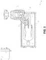
- FIG. 2depicts further aspects of the robotic system of FIG. 1 .
- FIG. 3illustrates an embodiment of the robotic system of FIG. 1 arranged for ureteroscopy.
- FIG. 4illustrates an embodiment of the robotic system of FIG. 1 arranged for a vascular procedure.
- FIG. 5illustrates an embodiment of a table-based robotic system arranged for a bronchoscopy procedure.
- FIG. 6provides an alternative view of the robotic system of FIG. 5 .
- FIG. 7illustrates an example system configured to stow robotic arm(s).
- FIG. 8illustrates an embodiment of a table-based robotic system configured for a ureteroscopy procedure.
- FIG. 9illustrates an embodiment of a table-based robotic system configured for a laparoscopic procedure.
- FIG. 10illustrates an embodiment of the table-based robotic system of FIGS. 5-9 with pitch or tilt adjustment.
- FIG. 11provides a detailed illustration of the interface between the table and the column of the table-based robotic system of FIGS. 5-10 .
- FIG. 12illustrates an exemplary instrument driver.
- FIG. 13illustrates an exemplary medical instrument with a paired instrument driver.
- FIG. 14illustrates an alternative design for an instrument driver and instrument where the axes of the drive units are parallel to the axis of the elongated shaft of the instrument.
- FIG. 15depicts a block diagram illustrating a localization system that estimates a location of one or more elements of the robotic systems of FIGS. 1-10 , such as the location of the instrument of FIGS. 13-14 , in accordance to an example embodiment.
- FIG. 16illustrates an example of an instrument navigating a luminal network.
- FIG. 17illustrates an example command console for a robotically-controlled surgical system.
- FIG. 18illustrates a distal end of an embodiment of a medical instrument.
- FIG. 19depicts a flowchart illustrating an example method for image-based branch detection and mapping.
- FIG. 20illustrates an example image of an interior of a branch of a luminal network.
- FIG. 21depicts a flowchart illustrating an example method for image-based branch detection.
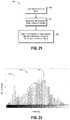
- FIG. 22illustrates an example histogram of pixel intensity values.
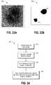
- FIGS. 23A and 23Billustrate example images illustrating image-based branch detection.
- FIG. 24depicts a flowchart illustrating an example method for image-based branch detection.
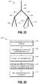
- FIG. 25illustrates a simplified view of a luminal network.
- FIG. 26depicts a flowchart illustrating an example method for image-based branch mapping.
- FIGS. 27A-27Cillustrate example steps in a method for image-based branch mapping.
- FIG. 28illustrates an example image illustrating image-based branch prediction.
- FIG. 29depicts a flowchart illustrating an example method for image-based branch detection and mapping.
- aspects of the present disclosuremay be integrated into a robotically-enabled medical system capable of performing a variety of medical procedures, including both minimally invasive, such as laparoscopy, and non-invasive, such as endoscopy, procedures.
- minimally invasivesuch as laparoscopy
- non-invasivesuch as endoscopy
- the systemmay be capable of performing bronchoscopy, ureteroscopy, gastroenterology, etc.
- the systemmay provide additional benefits, such as enhanced imaging and guidance to assist the physician. Additionally, the system may provide the physician with the ability to perform the procedure from an ergonomic position without the need for awkward arm motions and positions. Still further, the system may provide the physician with the ability to perform the procedure with improved ease of use such that one or more of the instruments of the system can be controlled by a single user.
- FIG. 1illustrates an embodiment of a cart-based robotically-enabled system 10 arranged for a diagnostic and/or therapeutic bronchoscopy procedure.
- the system 10may comprise a cart 11 having one or more robotic arms 12 to deliver a medical instrument, such as a steerable endoscope 13 , which may be a procedure-specific bronchoscope for bronchoscopy, to a natural orifice access point (i.e., the mouth of the patient positioned on a table in the present example) to deliver diagnostic and/or therapeutic tools.
- a medical instrumentsuch as a steerable endoscope 13
- a natural orifice access pointi.e., the mouth of the patient positioned on a table in the present example
- the cart 11may be positioned proximate to the patient's upper torso in order to provide access to the access point.
- the robotic arms 12may be actuated to position the bronchoscope relative to the access point.
- the arrangement in FIG. 1may also be utilized when performing a gastro-intestinal (GI) procedure with a gastroscope, a specialized endoscope for GI procedures.
- FIG. 2depicts an example embodiment of the cart in greater detail.
- the robotic arms 12may insert the steerable endoscope 13 into the patient robotically, manually, or a combination thereof.
- the steerable endoscope 13may comprise at least two telescoping parts, such as an inner leader portion and an outer sheath portion, each portion coupled to a separate instrument driver from the set of instrument drivers 28 , each instrument driver coupled to the distal end of an individual robotic arm.
- This linear arrangement of the instrument drivers 28which facilitates coaxially aligning the leader portion with the sheath portion, creates a “virtual rail” 29 that may be repositioned in space by manipulating the one or more robotic arms 12 into different angles and/or positions.
- the virtual rails described hereinare depicted in the Figures using dashed lines, and accordingly the dashed lines do not depict any physical structure of the system.
- Translation of the instrument drivers 28 along the virtual rail 29telescopes the inner leader portion relative to the outer sheath portion or advances or retracts the endoscope 13 from the patient.
- the angle of the virtual rail 29may be adjusted, translated, and pivoted based on clinical application or physician preference. For example, in bronchoscopy, the angle and position of the virtual rail 29 as shown represents a compromise between providing physician access to the endoscope 13 while minimizing friction that results from bending the endoscope 13 into the patient's mouth.
- the endoscope 13may be directed down the patient's trachea and lungs after insertion using precise commands from the robotic system until reaching the target destination or operative site. In order to enhance navigation through the patient's lung network and/or reach the desired target, the endoscope 13 may be manipulated to telescopically extend the inner leader portion from the outer sheath portion to obtain enhanced articulation and greater bend radius.
- the use of separate instrument drivers 28also allows the leader portion and sheath portion to be driven independent of each other.
- the endoscope 13may be directed to deliver a biopsy needle to a target, such as, for example, a lesion or nodule within the lungs of a patient.
- the needlemay be deployed down a working channel that runs the length of the endoscope to obtain a tissue sample to be analyzed by a pathologist.
- additional toolsmay be deployed down the working channel of the endoscope for additional biopsies.
- the endoscope 13may endoscopically deliver tools to resect the potentially cancerous tissue.
- diagnostic and therapeutic treatmentsmay need to be delivered in separate procedures.
- the endoscope 13may also be used to deliver a fiducial to “mark” the location of the target nodule as well. In other instances, diagnostic and therapeutic treatments may be delivered during the same procedure.
- the system 10may also include a movable tower 30 , which may be connected via support cables to the cart 11 to provide support for controls, electronics, fluidics, optics, sensors, and/or power to the cart 11 . Placing such functionality in the tower 30 allows for a smaller form factor cart 11 that may be more easily adjusted and/or re-positioned by an operating physician and his/her staff. Additionally, the division of functionality between the cart/table and the support tower 30 reduces operating room clutter and facilitates improving clinical workflow. While the cart 11 may be positioned close to the patient, the tower 30 may be stowed in a remote location to stay out of the way during a procedure.
- the tower 30may include component(s) of a computer-based control system that stores computer program instructions, for example, within a non-transitory computer-readable storage medium such as a persistent magnetic storage drive, solid state drive, etc.
- the execution of those instructionsmay control the entire system or sub-system(s) thereof.
- the instructionswhen executed by a processor of the computer system, the instructions may cause the components of the robotics system to actuate the relevant carriages and arm mounts, actuate the robotics arms, and control the medical instruments.
- the motors in the joints of the robotics armsmay position the arms into a certain posture.
- the tower 30may also include a pump, flow meter, valve control, and/or fluid access in order to provide controlled irrigation and aspiration capabilities to system that may be deployed through the endoscope 13 . These components may also be controlled using the computer system of tower 30 . In some embodiments, irrigation and aspiration capabilities may be delivered directly to the endoscope 13 through separate cable(s).
- the tower 30may include a voltage and surge protector designed to provide filtered and protected electrical power to the cart 11 , thereby avoiding placement of a power transformer and other auxiliary power components in the cart 11 , resulting in a smaller, more moveable cart 11 .
- the tower 30may also include support equipment for the sensors deployed throughout the robotic system 10 .
- the tower 30may include opto-electronics equipment for detecting, receiving, and processing data received from the optical sensors or cameras throughout the robotic system 10 . In combination with the control system, such opto-electronics equipment may be used to generate real-time images for display in any number of consoles deployed throughout the system, including in the tower 30 .
- the tower 30may also include an electronic subsystem for receiving and processing signals received from deployed electromagnetic (EM) sensors.
- EMelectromagnetic
- the tower 30may also be used to house and position an EM field generator for detection by EM sensors in or on the medical instrument.
- the tower 30may also include a console 31 in addition to other consoles available in the rest of the system, e.g., console mounted on top of the cart.
- the console 31may include a user interface and a display screen, such as a touchscreen, for the physician operator.
- Consoles in system 10are generally designed to provide both robotic controls as well as pre-operative and real-time information of the procedure, such as navigational and localization information of the endoscope 13 .
- the console 31When the console 31 is not the only console available to the physician, it may be used by a second operator, such as a nurse, to monitor the health or vitals of the patient and the operation of system, as well as provide procedure-specific data, such as navigational and localization information.
- the tower 30may be coupled to the cart 11 and endoscope 13 through one or more cables or connections (not shown).
- the support functionality from the tower 30may be provided through a single cable to the cart 11 , simplifying and de-cluttering the operating room.
- specific functionalitymay be coupled in separate cabling and connections. For example, while power may be provided through a single power cable to the cart, the support for controls, optics, fluidics, and/or navigation may be provided through a separate cable.
- FIG. 2provides a detailed illustration of an embodiment of the cart from the cart-based robotically-enabled system shown in FIG. 1 .
- the cart 11generally includes an elongated support structure 14 (often referred to as a “column”), a cart base 15 , and a console 16 at the top of the column 14 .
- the column 14may include one or more carriages, such as a carriage 17 (alternatively “arm support”) for supporting the deployment of one or more robotic arms 12 (three shown in FIG. 2 ).
- the carriage 17may include individually configurable arm mounts that rotate along a perpendicular axis to adjust the base of the robotic arms 12 for better positioning relative to the patient.
- the carriage 17also includes a carriage interface 19 that allows the carriage 17 to vertically translate along the column 14 .
- the carriage interface 19is connected to the column 14 through slots, such as slot 20 , that are positioned on opposite sides of the column 14 to guide the vertical translation of the carriage 17 .
- the slot 20contains a vertical translation interface to position and hold the carriage at various vertical heights relative to the cart base 15 .
- Vertical translation of the carriage 17allows the cart 11 to adjust the reach of the robotic arms 12 to meet a variety of table heights, patient sizes, and physician preferences.
- the individually configurable arm mounts on the carriage 17allow the robotic arm base 21 of robotic arms 12 to be angled in a variety of configurations.
- the slot 20may be supplemented with slot covers that are flush and parallel to the slot surface to prevent dirt and fluid ingress into the internal chambers of the column 14 and the vertical translation interface as the carriage 17 vertically translates.
- the slot coversmay be deployed through pairs of spring spools positioned near the vertical top and bottom of the slot 20 .
- the coversare coiled within the spools until deployed to extend and retract from their coiled state as the carriage 17 vertically translates up and down.
- the spring-loading of the spoolsprovides force to retract the cover into a spool when carriage 17 translates towards the spool, while also maintaining a tight seal when the carriage 17 translates away from the spool.
- the coversmay be connected to the carriage 17 using, for example, brackets in the carriage interface 19 to ensure proper extension and retraction of the cover as the carriage 17 translates.
- the column 14may internally comprise mechanisms, such as gears and motors, that are designed to use a vertically aligned lead screw to translate the carriage 17 in a mechanized fashion in response to control signals generated in response to user inputs, e.g., inputs from the console 16 .
- the robotic arms 12may generally comprise robotic arm bases 21 and end effectors 22 , separated by a series of linkages 23 that are connected by a series of joints 24 , each joint comprising an independent actuator, each actuator comprising an independently controllable motor.
- Each independently controllable jointrepresents an independent degree of freedom available to the robotic arm.
- Each of the arms 12have seven joints, and thus provide seven degrees of freedom. A multitude of joints result in a multitude of degrees of freedom, allowing for “redundant” degrees of freedom. Redundant degrees of freedom allow the robotic arms 12 to position their respective end effectors 22 at a specific position, orientation, and trajectory in space using different linkage positions and joint angles. This allows for the system to position and direct a medical instrument from a desired point in space while allowing the physician to move the arm joints into a clinically advantageous position away from the patient to create greater access, while avoiding arm collisions.
- the cart base 15balances the weight of the column 14 , carriage 17 , and arms 12 over the floor. Accordingly, the cart base 15 houses heavier components, such as electronics, motors, power supply, as well as components that either enable movement and/or immobilize the cart.
- the cart base 15includes rollable wheel-shaped casters 25 that allow for the cart to easily move around the room prior to a procedure. After reaching the appropriate position, the casters 25 may be immobilized using wheel locks to hold the cart 11 in place during the procedure.
- the console 16allows for both a user interface for receiving user input and a display screen (or a dual-purpose device such as, for example, a touchscreen 26 ) to provide the physician user with both pre-operative and intra-operative data.
- Potential pre-operative data on the touchscreen 26may include pre-operative plans, navigation and mapping data derived from pre-operative computerized tomography (CT) scans, and/or notes from pre-operative patient interviews.
- Intra-operative data on displaymay include optical information provided from the tool, sensor and coordinate information from sensors, as well as vital patient statistics, such as respiration, heart rate, and/or pulse.
- the console 16may be positioned and tilted to allow a physician to access the console from the side of the column 14 opposite carriage 17 . From this position the physician may view the console 16 , robotic arms 12 , and patient while operating the console 16 from behind the cart 11 .
- the console 16also includes a handle 27 to assist with maneuvering and stabilizing cart 11 .
- FIG. 3illustrates an embodiment of a robotically-enabled system 10 arranged for ureteroscopy.
- the cart 11may be positioned to deliver a ureteroscope 32 , a procedure-specific endoscope designed to traverse a patient's urethra and ureter, to the lower abdominal area of the patient.
- the ureteroscope 32may be directly aligned with the patient's urethra to reduce friction and forces on the sensitive anatomy in the area.
- the cart 11may be aligned at the foot of the table to allow the robotic arms 12 to position the ureteroscope 32 for direct linear access to the patient's urethra. From the foot of the table, the robotic arms 12 may insert ureteroscope 32 along the virtual rail 33 directly into the patient's lower abdomen through the urethra.
- the ureteroscope 32may be navigated into the bladder, ureters, and/or kidneys for diagnostic and/or therapeutic applications.
- the ureteroscope 32may be directed into the ureter and kidneys to break up kidney stone build up using laser or ultrasonic lithotripsy device deployed down the working channel of the ureteroscope 32 .
- the resulting stone fragmentsmay be removed using baskets deployed down the ureteroscope 32 .
- FIG. 4illustrates an embodiment of a robotically-enabled system similarly arranged for a vascular procedure.
- the system 10may be configured such the cart 11 may deliver a medical instrument 34 , such as a steerable catheter, to an access point in the femoral artery in the patient's leg.
- the femoral arterypresents both a larger diameter for navigation as well as relatively less circuitous and tortuous path to the patient's heart, which simplifies navigation.
- the cart 11may be positioned towards the patient's legs and lower abdomen to allow the robotic arms 12 to provide a virtual rail 35 with direct linear access to the femoral artery access point in the patient's thigh/hip region.
- the medical instrument 34may be directed and inserted by translating the instrument drivers 28 .
- the cartmay be positioned around the patient's upper abdomen in order to reach alternative vascular access points, such as, for example, the carotid and brachial arteries near the shoulder and wrist.
- Embodiments of the robotically-enabled medical systemmay also incorporate the patient's table. Incorporation of the table reduces the amount of capital equipment within the operating room by removing the cart, which allows greater access to the patient.
- FIG. 5illustrates an embodiment of such a robotically-enabled system arranged for a bronchoscopy procedure.
- System 36includes a support structure or column 37 for supporting platform 38 (shown as a “table” or “bed”) over the floor.
- the end effectors of the robotic arms 39 of the system 36comprise instrument drivers 42 that are designed to manipulate an elongated medical instrument, such as a bronchoscope 40 in FIG. 5 , through or along a virtual rail 41 formed from the linear alignment of the instrument drivers 42 .
- a C-arm for providing fluoroscopic imagingmay be positioned over the patient's upper abdominal area by placing the emitter and detector around table 38 .
- FIG. 6provides an alternative view of the system 36 without the patient and medical instrument for discussion purposes.
- the column 37may include one or more carriages 43 shown as ring-shaped in the system 36 , from which the one or more robotic arms 39 may be based.
- the carriages 43may translate along a vertical column interface 44 that runs the length of the column 37 to provide different vantage points from which the robotic arms 39 may be positioned to reach the patient.
- the carriage(s) 43may rotate around the column 37 using a mechanical motor positioned within the column 37 to allow the robotic arms 39 to have access to multiples sides of the table 38 , such as, for example, both sides of the patient.
- the carriagesmay be individually positioned on the column and may translate and/or rotate independent of the other carriages.
- carriages 43need not surround the column 37 or even be circular, the ring-shape as shown facilitates rotation of the carriages 43 around the column 37 while maintaining structural balance. Rotation and translation of the carriages 43 allows the system to align the medical instruments, such as endoscopes and laparoscopes, into different access points on the patient.
- the arms 39may be mounted on the carriages through a set of arm mounts 45 comprising a series of joints that may individually rotate and/or telescopically extend to provide additional configurability to the robotic arms 39 .
- the arm mounts 45may be positioned on the carriages 43 such that, when the carriages 43 are appropriately rotated, the arm mounts 45 may be positioned on either the same side of table 38 (as shown in FIG. 6 ), on opposite sides of table 38 (as shown in FIG. 9 ), or on adjacent sides of the table 38 (not shown).
- the column 37structurally provides support for the table 38 , and a path for vertical translation of the carriages. Internally, the column 37 may be equipped with lead screws for guiding vertical translation of the carriages, and motors to mechanize the translation of said carriages based the lead screws. The column 37 may also convey power and control signals to the carriage 43 and robotic arms 39 mounted thereon.
- the table base 46serves a similar function as the cart base 15 in cart 11 shown in FIG. 2 , housing heavier components to balance the table/bed 38 , the column 37 , the carriages 43 , and the robotic arms 39 .
- the table base 46may also incorporate rigid casters to provide stability during procedures. Deployed from the bottom of the table base 46 , the casters may extend in opposite directions on both sides of the base 46 and retract when the system 36 needs to be moved.
- the system 36may also include a tower (not shown) that divides the functionality of system 36 between table and tower to reduce the form factor and bulk of the table.
- the towermay be provide a variety of support functionalities to table, such as processing, computing, and control capabilities, power, fluidics, and/or optical and sensor processing.
- the towermay also be movable to be positioned away from the patient to improve physician access and de-clutter the operating room. Additionally, placing components in the tower allows for more storage space in the table base for potential stowage of the robotic arms.
- the towermay also include a console that provides both a user interface for user input, such as keyboard and/or pendant, as well as a display screen (or touchscreen) for pre-operative and intra-operative information, such as real-time imaging, navigation, and tracking information.
- a table basemay stow and store the robotic arms when not in use.
- FIG. 7illustrates a system 47 that stows robotic arms in an embodiment of the table-based system.
- carriages 48may be vertically translated into base 49 to stow robotic arms 50 , arm mounts 51 , and the carriages 48 within the base 49 .
- Base covers 52may be translated and retracted open to deploy the carriages 48 , arm mounts 51 , and arms 50 around column 53 , and closed to stow to protect them when not in use.
- the base covers 52may be sealed with a membrane 54 along the edges of its opening to prevent dirt and fluid ingress when closed.
- FIG. 8illustrates an embodiment of a robotically-enabled table-based system configured for a ureteroscopy procedure.
- the table 38may include a swivel portion 55 for positioning a patient off-angle from the column 37 and table base 46 .
- the swivel portion 55may rotate or pivot around a pivot point (e.g., located below the patient's head) in order to position the bottom portion of the swivel portion 55 away from the column 37 .
- the pivoting of the swivel portion 55allows a C-arm (not shown) to be positioned over the patient's lower abdomen without competing for space with the column (not shown) below table 38 .
- the robotic arms 39may directly insert a ureteroscope 56 along a virtual rail 57 into the patient's groin area to reach the urethra.
- stirrups 58may also be fixed to the swivel portion 55 of the table 38 to support the position of the patient's legs during the procedure and allow clear access to the patient's groin area.
- FIG. 9illustrates an embodiment of a robotically-enabled table-based system configured for a laparoscopic procedure. As shown in FIG.
- the carriages 43 of the system 36may be rotated and vertically adjusted to position pairs of the robotic arms 39 on opposite sides of the table 38 , such that laparoscopes 59 may be positioned using the arm mounts 45 to be passed through minimal incisions on both sides of the patient to reach his/her abdominal cavity.
- FIG. 10illustrates an embodiment of the robotically-enabled medical system with pitch or tilt adjustment.
- the system 36may accommodate tilt of the table 38 to position one portion of the table at a greater distance from the floor than the other.
- the arm mounts 45may rotate to match the tilt such that the arms 39 maintain the same planar relationship with table 38 .
- the column 37may also include telescoping portions 60 that allow vertical extension of column 37 to keep the table 38 from touching the floor or colliding with base 46 .
- FIG. 11provides a detailed illustration of the interface between the table 38 and the column 37 .
- Pitch rotation mechanism 61may be configured to alter the pitch angle of the table 38 relative to the column 37 in multiple degrees of freedom.
- the pitch rotation mechanism 61may be enabled by the positioning of orthogonal axes 1 , 2 at the column-table interface, each axis actuated by a separate motor 3 , 4 responsive to an electrical pitch angle command. Rotation along one screw 5 would enable tilt adjustments in one axis 1 , while rotation along the other screw 6 would enable tilt adjustments along the other axis 2 .
- pitch adjustmentsare particularly useful when trying to position the table in a Trendelenburg position, i.e., position the patient's lower abdomen at a higher position from the floor than the patient's lower abdomen, for lower abdominal surgery.
- the Trendelenburg positioncauses the patient's internal organs to slide towards his/her upper abdomen through the force of gravity, clearing out the abdominal cavity for minimally invasive tools to enter and perform lower abdominal surgical procedures, such as laparoscopic prostatectomy.
- the end effectors of the system's robotic armscomprise (i) an instrument driver (alternatively referred to as “instrument drive mechanism” or “instrument device manipulator”) that incorporate electro-mechanical means for actuating the medical instrument and (ii) a removable or detachable medical instrument which may be devoid of any electro-mechanical components, such as motors.
- instrument driveralternatively referred to as “instrument drive mechanism” or “instrument device manipulator”
- instrument device manipulatora removable or detachable medical instrument which may be devoid of any electro-mechanical components, such as motors.
- FIG. 12illustrates an example instrument driver.
- instrument driver 62Positioned at the distal end of a robotic arm, instrument driver 62 comprises of one or more drive units 63 arranged with parallel axes to provide controlled torque to a medical instrument via drive shafts 64 .
- Each drive unit 63comprises an individual drive shaft 64 for interacting with the instrument, a gear head 65 for converting the motor shaft rotation to a desired torque, a motor 66 for generating the drive torque, an encoder 67 to measure the speed of the motor shaft and provide feedback to the control circuitry, and control circuity 68 for receiving control signals and actuating the drive unit.
- Each drive unit 63being independent controlled and motorized, the instrument driver 62 may provide multiple (four as shown in FIG. 12 ) independent drive outputs to the medical instrument.
- the control circuitry 68would receive a control signal, transmit a motor signal to the motor 66 , compare the resulting motor speed as measured by the encoder 67 with the desired speed, and modulate the motor signal to generate the desired torque
- the robotic systemmay incorporate a drive interface, such as a sterile adapter connected to a sterile drape, that sits between the instrument driver and the medical instrument.
- a drive interfacesuch as a sterile adapter connected to a sterile drape
- the chief purpose of the sterile adapteris to transfer angular motion from the drive shafts of the instrument driver to the drive inputs of the instrument while maintaining physical separation, and thus sterility, between the drive shafts and drive inputs.
- an example sterile adaptermay comprise of a series of rotational inputs and outputs intended to be mated with the drive shafts of the instrument driver and drive inputs on the instrument.
- the sterile drapecomprised of a thin, flexible material such as transparent or translucent plastic, is designed to cover the capital equipment, such as the instrument driver, robotic arm, and cart (in a cart-based system) or table (in a table-based system).
- the capital equipmentsuch as the instrument driver, robotic arm, and cart (in a cart-based system) or table (in a table-based system).
- Use of the drapewould allow the capital equipment to be positioned proximate to the patient while still being located in an area not requiring sterilization (i.e., non-sterile field).
- the medical instrumentmay interface with the patient in an area requiring sterilization (i.e., sterile field).
- FIG. 13illustrates an example medical instrument with a paired instrument driver.
- medical instrument 70comprises an elongated shaft 71 (or elongate body) and an instrument base 72 .
- the instrument base 72also referred to as an “instrument handle” due to its intended design for manual interaction by the physician, may generally comprise rotatable drive inputs 73 , e.g., receptacles, pulleys or spools, that are designed to be mated with drive outputs 74 that extend through a drive interface on instrument driver 75 at the distal end of robotic arm 76 .
- the mated drive inputs 73 of instrument base 72may share axes of rotation with the drive outputs 74 in the instrument driver 75 to allow the transfer of torque from drive outputs 74 to drive inputs 73 .
- the drive outputs 74may comprise splines that are designed to mate with receptacles on the drive inputs 73 .
- the elongated shaft 71is designed to be delivered through either an anatomical opening or lumen, e.g., as in endoscopy, or a minimally invasive incision, e.g., as in laparoscopy.
- the elongated shaft 66may be either flexible (e.g., having properties similar to an endoscope) or rigid (e.g., having properties similar to a laparoscope) or contain a customized combination of both flexible and rigid portions.
- the distal end of a rigid elongated shaftmay be connected to an end effector comprising a jointed wrist formed from a clevis with an axis of rotation and a surgical tool, such as, for example, a grasper or scissors, that may be actuated based on force from the tendons as the drive inputs rotate in response to torque received from the drive outputs 74 of the instrument driver 75 .
- a surgical toolsuch as, for example, a grasper or scissors
- the distal end of a flexible elongated shaftmay include a steerable or controllable bending section that may be articulated and bent based on torque received from the drive outputs 74 of the instrument driver 75 .
- Torque from the instrument driver 75is transmitted down the elongated shaft 71 using tendons within the shaft 71 .
- These individual tendonssuch as pull wires, may be individually anchored to individual drive inputs 73 within the instrument handle 72 .
- the tendonsare directed down one or more pull lumens within the elongated shaft 71 and anchored at the distal portion of the elongated shaft 71 .
- these tendonsmay be coupled to a distally mounted end effector, such as a wrist, grasper, or scissor. Under such an arrangement, torque exerted on drive inputs 73 would transfer tension to the tendon, thereby causing the end effector to actuate in some way.
- the tendonmay cause a joint to rotate about an axis, thereby causing the end effector to move in one direction or another.
- the tendonmay be connected to one or more jaws of a grasper at distal end of the elongated shaft 71 , where tension from the tendon cause the grasper to close.
- the tendonsmay be coupled to a bending or articulating section positioned along the elongated shaft 71 (e.g., at the distal end) via adhesive, control ring, or other mechanical fixation.
- a bending or articulating sectionpositioned along the elongated shaft 71 (e.g., at the distal end) via adhesive, control ring, or other mechanical fixation.
- torque exerted on drive inputs 73would be transmitted down the tendons, causing the softer, bending section (sometimes referred to as the articulable section or region) to bend or articulate.
- the angle of the spiraling and/or spacing there betweenmay be altered or engineered for specific purposes, wherein tighter spiraling exhibits lesser shaft compression under load forces, while lower amounts of spiraling results in greater shaft compression under load forces, but also exhibits limits bending.
- the pull lumensmay be directed parallel to the longitudinal axis of the elongated shaft 71 to allow for controlled articulation in the desired bending or articulable sections.
- the elongated shaft 71houses a number of components to assist with the robotic procedure.
- the shaftmay comprise of a working channel for deploying surgical tools, irrigation, and/or aspiration to the operative region at the distal end of the shaft 71 .
- the shaft 71may also accommodate wires and/or optical fibers to transfer signals to/from an optical assembly at the distal tip, which may include of an optical camera.
- the shaft 71may also accommodate optical fibers to carry light from proximally-located light sources, such as light emitting diodes, to the distal end of the shaft.
- the distal tipmay also comprise the opening of a working channel for delivering tools for diagnostic and/or therapy, irrigation, and aspiration to an operative site.
- the distal tipmay also include a port for a camera, such as a fiberscope or a digital camera, to capture images of an internal anatomical space.
- the distal tipmay also include ports for light sources for illuminating the anatomical space when using the camera.
- the drive shaft axesand thus the drive input axes, are orthogonal to the axis of the elongated shaft.
- This arrangementcomplicates roll capabilities for the elongated shaft 71 .
- Rolling the elongated shaft 71 along its axis while keeping the drive inputs 73 staticresults in undesirable tangling of the tendons as they extend off the drive inputs 73 and enter pull lumens within the elongate shaft 71 .
- the resulting entanglement of such tendonsmay disrupt any control methods intended to predict movement of the flexible elongate shaft during an endoscopic procedure.
- FIG. 14illustrates an alternative design for an instrument driver and instrument where the axes of the drive units are parallel to the axis of the elongated shaft of the instrument.
- a circular instrument driver 80comprises four drive units with their drive outputs 81 aligned in parallel at the end of a robotic arm 82 .
- the drive units, and their respective drive outputs 81are housed in a rotational assembly 83 of the instrument driver 80 that is driven by one of the drive units within the assembly 83 .
- the rotational assembly 83rotates along a circular bearing that connects the rotational assembly 83 to the non-rotational portion 84 of the instrument driver.
- Power and controls signalsmay be communicated from the non-rotational portion 84 of the instrument driver 80 to the rotational assembly 83 through electrical contacts may be maintained through rotation by a brushed slip ring connection (not shown).
- the rotational assembly 83may be responsive to a separate drive unit that is integrated into the non-rotatable portion 84 , and thus not in parallel to the other drive units.
- the rotational mechanism 83allows the instrument driver 80 to rotate the drive units, and their respective drive outputs 81 , as a single unit around an instrument driver axis 85 .
- an instrument 86may comprise of an elongated shaft portion 88 and an instrument base 87 (shown with a transparent external skin for discussion purposes) comprising a plurality of drive inputs 89 (such as receptacles, pulleys, and spools) that are configured to receive the drive outputs 81 in the instrument driver 80 .
- instrument shaft 88extends from the center of instrument base 87 with an axis substantially parallel to the axes of the drive inputs 89 , rather than orthogonal as in the design of FIG. 13 .
- the medical instrument 86When coupled to the rotational assembly 83 of the instrument driver 80 , the medical instrument 86 , comprising instrument base 87 and instrument shaft 88 , rotates in combination with the rotational assembly 83 about the instrument driver axis 85 . Since the instrument shaft 88 is positioned at the center of instrument base 87 , the instrument shaft 88 is coaxial with instrument driver axis 85 when attached. Thus, rotation of the rotational assembly 83 causes the instrument shaft 88 to rotate about its own longitudinal axis. Moreover, as the instrument base 87 rotates with the instrument shaft 88 , any tendons connected to the drive inputs 89 in the instrument base 87 are not tangled during rotation. Accordingly, the parallelism of the axes of the drive outputs 81 , drive inputs 89 , and instrument shaft 88 allows for the shaft rotation without tangling any control tendons.
- the robotic systems contemplated by this disclosurecan provide for non-radiation-based navigational and localization means to reduce physician exposure to radiation and reduce the amount of equipment within the operating room.
- the term “localization”may refer to determining and/or monitoring the position of objects in a reference coordinate system. Technologies such as pre-operative mapping, computer vision, real-time EM tracking, and robot command data may be used individually or in combination to achieve a radiation-free operating environment. In other cases, where radiation-based imaging modalities are still used, the pre-operative mapping, computer vision, real-time EM tracking, and robot command data may be used individually or in combination to improve upon the information obtained solely through radiation-based imaging modalities.
- FIG. 15is a block diagram illustrating a localization system 90 that estimates a location of one or more elements of the robotic system, such as the location of the instrument, in accordance to an example embodiment.
- the localization system 90may be a set of one or more computer devices configured to execute one or more instructions.
- the computer devicesmay be embodied by a processor (or processors) and computer-readable memory in one or more components discussed above.
- the computer devicesmay be in the tower 30 shown in FIG. 1 , the cart shown in FIGS. 1-4 , the beds shown in FIGS. 5-10 , etc.
- the localization system 90may include a localization module 95 that processes input data 91 - 94 to generate location data 96 for the distal tip of a medical instrument.
- the location data 96may be data or logic that represents a location and/or orientation of the distal end of the instrument relative to a frame of reference.
- the frame of referencecan be a frame of reference relative to the anatomy of the patient or to a known object, such as an EM field generator (see discussion below for the EM field generator).
- Pre-operative mappingmay be accomplished through the use of the collection of low dose CT scans.
- Pre-operative CT scansgenerate two-dimensional images, each representing a “slice” of a cutaway view of the patient's internal anatomy.
- image-based models for anatomical cavities, spaces and structures of the patient's anatomy, such as a patient lung networkmay be generated.
- Techniquessuch as center-line geometry may be determined and approximated from the CT images to develop a three-dimensional volume of the patient's anatomy, referred to as preoperative model data 91 .
- center-line geometryis discussed in U.S. patent application Ser. No. 14/523,760, the contents of which are herein incorporated in its entirety.
- Network topological modelsmay also be derived from the CT-images, and are particularly appropriate for bronchoscopy.
- the instrumentmay be equipped with a camera to provide vision data (or image data) 92 .
- the localization module 95may process the vision data to enable one or more vision-based (or image-based) location tracking modules or features.
- the preoperative model datamay be used in conjunction with the vision data 92 to enable computer vision-based tracking of the medical instrument (e.g., an endoscope or an instrument advance through a working channel of the endoscope).
- the robotic systemmay generate a library of expected endoscopic images from the model based on the expected path of travel of the endoscope, each image linked to a location within the model. Intra-operatively, this library may be referenced by the robotic system in order to compare real-time images captured at the camera (e.g., a camera at a distal end of the endoscope) to those in the image library to assist localization.
- Some computer vision-based tracking techniquesuse feature tracking to determine motion of the camera, and thus the endoscope.
- Some feature of the localization module 95may identify circular geometries in the preoperative model data 91 that correspond to anatomical lumens and track the change of those geometries to determine which anatomical lumen was selected, as well as the relative rotational and/or translational motion of the camera. Use of a topological map may further enhance vision-based methods or techniques.
- Optical flowanother computer vision-based technique, may analyze the displacement and translation of image pixels in a video sequence in the vision data 92 to infer camera movement. Through the comparison of multiple frames over multiple iterations, movement and location of the camera (and thus the endoscope) may be determined.
- the localization module 95may use real-time EM tracking to generate a real-time location of the endoscope in a global coordinate system that may be registered to the patient's anatomy, represented by the preoperative model.
- EM trackingan EM sensor (or tracker) comprising of one or more sensor coils embedded in one or more locations and orientations in a medical instrument (e.g., an endoscopic tool) measures the variation in the EM field created by one or more static EM field generators positioned at a known location.
- the location information detected by the EM sensorsis stored as EM data 93 .
- the EM field generator(or transmitter), may be placed close to the patient to create a low intensity magnetic field that the embedded sensor may detect.
- the magnetic fieldinduces small currents in the sensor coils of the EM sensor, which may be analyzed to determine the distance and angle between the EM sensor and the EM field generator.
- These distances and orientationsmay be intra-operatively “registered” to the patient anatomy (e.g., the preoperative model) in order to determine the geometric transformation that aligns a single location in the coordinate system with a position in the pre-operative model of the patient's anatomy.
- an embedded EM tracker in one or more positions of the medical instrumente.g., the distal tip of an endoscope
- Robotic command and kinematics data 94may also be used by the localization module 95 to provide localization data 96 for the robotic system.
- Device pitch and yaw resulting from articulation commandsmay be determined during pre-operative calibration. Intra-operatively, these calibration measurements may be used in combination with known insertion depth information to estimate the position of the instrument. Alternatively, these calculations may be analyzed in combination with EM, vision, and/or topological modeling to estimate the position of the medical instrument within the network.
- FIG. 15shows, a number of other input data can be used by the localization module 95 .
- an instrument utilizing shape-sensing fibercan provide shape data that the localization module 95 can use to determine the location and shape of the instrument.
- the localization module 95may use the input data 91 - 94 in combination(s). In some cases, such a combination may use a probabilistic approach where the localization module 95 assigns a confidence weight to the location determined from each of the input data 91 - 94 . Thus, where the EM data may not be reliable (as may be the case where there is EM interference) the confidence of the location determined by the EM data 93 can be decrease and the localization module 95 may rely more heavily on the vision data 92 and/or the robotic command and kinematics data 94 .
- the robotic systems discussed hereinmay be designed to incorporate a combination of one or more of the technologies above.
- the robotic system's computer-based control systembased in the tower, bed and/or cart, may store computer program instructions, for example, within a non-transitory computer-readable storage medium such as a persistent magnetic storage drive, solid state drive, or the like, that, upon execution, cause the system to receive and analyze sensor data and user commands, generate control signals throughout the system, and display the navigational and localization data, such as the position of the instrument within the global coordinate system, anatomical map, etc.
- a medical instrumentsuch as a robotically-controlled medical instrument
- the instrumentmay be positioned within a luminal network of the patient.
- luminal networkrefers to any cavity structure within the body, whether comprising a plurality of lumens or branches (e.g., a plurality of branched lumens, as in the lung or blood vessels) or a single lumen or branch (e.g., within the gastrointestinal tract).
- the instrumentmay be moved (e.g., navigated, guided, driven, etc.) through the luminal network to one or more areas of interest. Movement of the instrument through the system may be aided by the navigation or localization system 90 discussed above, which can provide positional information about the instrument to a physician controlling the robotic system.
- FIG. 16illustrates an example luminal network 130 of a patient.
- the luminal network 130is a bronchial network of airways 150 (i.e., lumens, branches) of the patient's lung.
- the illustrated luminal network 130is a bronchial network of airways within the patient's lung, this disclosure is not limited to only the illustrated example.
- the robotic systems and methods described hereinmay be used to navigate any type of luminal network, such as bronchial networks, renal networks, cardiovascular networks (e.g., arteries and veins), gastrointestinal tracts, urinary tracts, etc.
- the luminal network 130comprises a plurality of lumens 150 that are arranged in a branched structure.
- the luminal network 130comprises a three-dimensional structure.
- FIG. 16represents the luminal network 130 as a two-dimensional structure. This should not be construed to limit the present disclosure to two-dimensional luminal networks in any way.
- FIG. 16also illustrates an example of a medical instrument positioned within the luminal network 130 .
- the medical instrumentis navigated through the luminal network 130 towards an area of interest (e.g., nodule 155 ) for diagnosis and/or treatment.
- an area of intereste.g., nodule 155
- the nodule 155is located at the periphery of the airways 150 , although the area(s) of interest can be positioned anywhere within the luminal network 130 depending on the patient and procedure.
- the medical instrumentcomprises an endoscope 115 .
- the endoscope 115can include a sheath 120 and a leader 145 .
- the sheath 120 and the leader 145may be arranged in a telescopic manner.
- the leader 145may be slidably positioned inside a working channel of the sheath 120 .
- the sheath 120may have a first diameter, and its distal end may not be able to be positioned through the smaller-diameter airways 150 around the nodule 155 .
- the leader 145may be configured to extend from the working channel of the sheath 120 the remaining distance to the nodule 155 .
- the leader 145may have a lumen through which instruments, for example biopsy needles, cytology brushes, and/or tissue sampling forceps, can be passed to the target tissue site of the nodule 155 .
- both the distal end of the sheath 120 and the distal end of the leader 145can be provided with EM instrument sensors (e.g., EM instrument sensors 305 in FIG. 18 ) for tracking their position within the airways 150 .
- This telescopic arrangement of the sheath 120 and the leader 145may allow for a thinner design of the endoscope 115 and may improve a bend radius of the endoscope 115 while providing a structural support via the sheath 120 .
- the overall diameter of the endoscope 115may be small enough to reach the periphery without the telescopic arrangement, or may be small enough to get close to the periphery (e.g., within 2.5-3 cm) to deploy medical instruments through a non-steerable catheter.
- the medical instruments deployed through the endoscope 115may be equipped with EM instrument sensors (e.g., EM instrument sensors 305 in FIG. 18 ), and the image-based branch detection and mapping navigation techniques described below can be applied to such medical instruments.
- the instrumente.g., endoscope
- the instrumentmust be navigated or guided through the lumens or branches 150 of the luminal network.
- An operator(such as a physician) can control the robotic system to navigate the instrument to the nodule 155 .
- the operatormay provide inputs for controlling the robotic system.
- FIG. 17illustrates an example command console 200 that can be used with some implementations of the robotic systems described herein.
- the operatormay provide the inputs for controlling the robotic system, for example, to navigate or guide the instrument to an area of interest such as nodule 155 , via the command console 200 .
- the command console 200may be embodied in a wide variety of arrangements or configurations.
- the command console 200includes a console base 201 , displays 202 (e.g., monitors), and one or more control modules (e.g., keyboard 203 and joystick 204 ).
- a user 205e.g., the operator or physician
- can remotely control the medical robotic systeme.g., the systems described with reference to FIGS. 1-15 ) from an ergonomic position using the command console 200 .
- the displays 202may include electronic monitors (e.g., LCD displays, LED displays, touch-sensitive displays), virtual reality viewing devices (e.g., goggles or glasses), and/or other display devices.
- one or more of the displays 202displays position information about the instrument, for example, as determined by the localization system 90 ( FIG. 15 ).
- one or more of the displays 202displays a preoperative model of the patient's luminal network 130 .
- the positional informationcan be overlaid on the preoperative model.
- the displays 202can also display image information received from a camera or another sensing device positioned on the instrument within the luminal network 130 .
- a model or representation of the instrumentis displayed with the preoperative model to help indicate a status of a surgical or medical procedure.
- the console base 201includes a central processing unit (CPU or processor), a memory unit (computer-readable memory), a data bus, and associated data communication ports that are responsible for interpreting and processing signals such as camera imagery and tracking sensor data, e.g., from a medical instrument positioned within a luminal network of a patient.
- CPUcentral processing unit
- memory unitcomputer-readable memory
- data busand associated data communication ports that are responsible for interpreting and processing signals such as camera imagery and tracking sensor data, e.g., from a medical instrument positioned within a luminal network of a patient.
- the console base 201may also process commands and instructions provided by the user 205 through control modules 203 , 204 .
- the control modulesmay include other devices, such as computer mice, trackpads, trackballs, control pads, controllers such as handheld remote controllers, and sensors (e.g., motion sensors or cameras) that capture hand gestures and finger gestures.
- a controllercan include a set of user inputs (e.g., buttons, joysticks, directional pads, etc.) mapped to an operation of the instrument (e.g., articulation, driving, water irrigation, etc.).
- the user 205may navigate an instrument through the luminal network 130 .
- FIG. 18illustrates a detail view of a distal end of an example medical instrument 300 .
- the medical instrument 300 of FIG. 18may be representative of the endoscope 115 or steerable catheter 145 of FIG. 16 .
- the medical instrument 300may be representative of any medical instrument described throughout the disclosure, such as the endoscope 13 of FIG. 1 , the ureteroscope 32 of FIG. 3 , the laparoscope 59 of FIG. 9 , etc.
- the distal end of the instrument 300includes an imaging device 315 , illumination sources 310 , and ends of EM sensor coils 305 , which form an EM instrument sensor.
- the distal endfurther includes an opening to a working channel 320 of the instrument 300 through which surgical instruments, such as biopsy needles, cytology brushes, forceps, etc., may be inserted along the instrument shaft, allowing access to the area near the instrument tip.
- EM coils 305 located on the distal end of the instrument 300may be used with an EM tracking system to detect the position and orientation of the distal end of the instrument 300 while it is positioned within a luminal network.
- the coils 305may be angled to provide sensitivity to EM fields along different axes, giving the disclosed navigational systems the ability to measure a full 6 degrees of freedom (DoF): three positional DoF and three angular DoF.
- DoFdegrees of freedom
- only a single coil 305may be disposed on or within the distal end with its axis oriented along the instrument shaft. Due to the rotational symmetry of such a system, it may be insensitive to roll about its axis, so only five degrees of freedom may be detected in such an implementation.
- other types of position sensorsmay be employed.
- the illumination sources 310provide light to illuminate a portion of an anatomical space.
- the illumination sourcescan each be one or more light-emitting devices configured to emit light at a selected wavelength or range of wavelengths.
- the wavelengthscan be any suitable wavelength, for example, visible spectrum light, infrared light, x-ray (e.g., for fluoroscopy), to name a few examples.
- illumination sources 310can include light-emitting diodes (LEDs) located at the distal end of the instrument 300 .
- illumination sources 310can include one or more fiber optic fibers extending through a length of the endoscope to transmit light through the distal end from a remote light source, for example, an x-ray generator. Where the distal end includes multiple illumination sources 310 these can each be configured to emit the same or different wavelengths of light as one another.
- the imaging device 315can include any photosensitive substrate or structure configured to convert energy representing received light into electric signals, for example, a charge-coupled device (CCD) or complementary metal-oxide semiconductor (CMOS) image sensor.
- CCDcharge-coupled device
- CMOScomplementary metal-oxide semiconductor
- Some examples of imaging device 315can include one or more optical fibers, for example, a fiber optic bundle, configured to transmit light representing an image from the distal end 300 of the endoscope to an eyepiece and/or image sensor near the proximal end of the endoscope.
- Imaging device 315can additionally include one or more lenses and/or wavelength pass or cutoff filters as required for various optical designs. The light emitted from the illumination sources 310 allows the imaging device 315 to capture images of the interior of a patient's luminal network.
- imagescan then be transmitted as individual frames or series of successive frames (e.g., a video) to a computer system such as command console 200 .
- a computer systemsuch as command console 200 .
- the images captured by the imaging device 315e.g., vision data 92 of FIG. 15
- the navigation or localization system 95can be utilized by the navigation or localization system 95 to determine or estimate the position of the instrument (e.g., the position of the distal tip of the instrument 300 ) within a luminal network.
- image-based branch detectionmay refer to identifying within an image one or more openings associated with one or more branches of a luminal network.
- an image-based branch detection systemmay capture an image of an interior of a luminal network using an imaging device positioned on an instrument within the luminal network, and the image-based branch detection system may analyze the to detect one or more openings associated with subsequent branches of the luminal network.
- image-based branch mappingmay refer to mapping the detected one or more openings to corresponding branches of the luminal network.
- an image-based branch mapping systemmay be configured to identify which one or more branches of a luminal network correspond to the one or more detected openings within the image.
- These systems and techniquesmay be used to determine or estimate the position of an instrument within the luminal network. In certain implementations, these systems and techniques may be used in conjunction with various other navigation and localization modalities (e.g., as described above with reference to FIG. 15 ).
- the ability to navigate inside a luminal networkmay be a feature of the robotically-controlled surgical systems described herein.
- navigationmay refer to locating or determining the position of an instrument within a luminal network. The determined position may be used to help guide the instrument to one or more particular areas of interest within the luminal network.
- the robotically-controlled surgical systemsutilize one or more independent sensing modalities to provide intra-operative navigation for the instrument.
- the independent sensing modalitiesmay position data (e.g., EM data 93 ), vision data 92 , and/or robotic command and kinematics data 94 .
- These independent sensing modalitiesmay include estimation modules configured to provide independent estimates of position.
- Image-based branch detection and mappingmay provide an independent sensing modality, based on vision data 92 , that can provide an independent estimate of position.
- image-based branch detection and mappingprovides a combination of a sensing modality and a state/position estimation module that estimates which lumen or branch of a luminal network an imaging device of the instrument is in based on an image or images captured by the imaging device.
- the estimate provided by image-based branch detection and mappingmay be used alone or with other position estimates to determine a final position estimate that can be used by the system or displayed to the user.
- This disclosurerefers to one such module—an image-based branch detection and mapping module—that detects branch openings based on vision data 92 (e.g., based on a single image) and estimates the current position of the instrument by mapping those detected branch openings to specific anatomical branches in the luminal network.
- the image-based branch detection and mapping modulemay use a current or previous position estimate determined by navigation or localization system 90 (that can be based on one or a plurality of sensing modalities) to map the detected openings to the specific anatomical branches in the luminal network.
- the image-based branch detection and mapping systems and methods described hereinmay be configured to provide a position estimate to the navigation or localization module 95 of where the instrument is positioned in the luminal network.
- the image-based branch detection and mapping systems and methods described hereinmay be independent of any other modality.
- the image-based branch detection and mapping systems and methods described hereinmay base its estimate on prior position estimates determined using a plurality sensing modalities.
- FIG. 19illustrates an example method 400 for image-based branch detection and mapping.
- the method 400may be implemented in various robotically-controlled surgical systems as described herein.
- the method 400may include two steps or blocks: detecting branch openings in an image (block 402 ) and mapping the detected openings to branches of the luminal network (block 404 ).
- the method 400detects branch openings within an image.
- an instrumentmay be positioned within a luminal network (see FIG. 16 ).
- the instrumentmay include an imaging device 315 (such as a camera) positioned thereon.
- the imaging device 315may capture images of the interior of the luminal network.
- the imaging device 315may capture an image of the interior of the particular branch of the luminal network in which the instrument is currently positioned.
- the method 400can analyze the image to detect one or more openings within the image. The one or more openings may connect one or more subsequent branches of the luminal network to the current branch in which the instrument is positioned.
- block 402may involve image analysis that processes an image to determine whether the image contains one or more branch openings. In certain implementations, if the image is determined to contain one or more branch openings, various features of the openings may also be determined. Such features may include identifying a centroid of the detected one or more branch openings and/or identifying a shape or contour of the detected one or more branch openings.
- Block 402detection of branch openings in an image
- Block 402may be referred to herein as image-based branch detection, and is described in greater detail in section 3.B below.
- the method 400maps the one or more detected branch openings to specific branches of the luminal network.
- the method 400determines which branches of the luminal network are associated with the detected openings.
- block 404may include determining a set of expected subsequent branches (for example, based on a current position estimate and a preoperative model of the luminal network) and matching features of the expected subsequent branches to the detected branch openings.
- Block 404mapping detected openings to branches of the luminal network
- image-based branch mappingis described in greater detail in section 3.0 below.
- the method 400may provide an estimate of position for the instrument. For example, using the method 400 , the system or the instrument can identify which branches the instrument “sees” and use this information to estimate where the instrument is within the luminal network.
- Image-based branch detectionmay analyze an image captured by the imaging device 315 of an instrument positioned within a luminal network to detect one or more branch openings in the image. For example, image-based branch detection analyzes an image of an interior of a branch to detect whether one or more openings connected subsequent branches of the luminal network to the current branch are present in the image.
- FIG. 20provides an example image 500 of an interior of a branch of a luminal network.
- the image 500is an interior image of an airway of a lung, although the image 500 may be representative of any type of luminal network.
- Two branch openings 502are present in the image 500 .
- the branch openings 502connect subsequent branches (e.g., subsequent airways) to the current branch.
- Image-based branch detectioncan include a method whereby a computer system can recognize the branch openings 502 computationally.
- the image 500includes two classes of pixels: (1) pixels representing walls of the luminal network (e.g., tissue), and (2) pixels representing openings.
- the image-based branch detectioncan systematically detect these two classes of pixels to identify and detect branch openings within an image.
- FIG. 21illustrates an example method 600 for image-based branch detection.
- the method 600begins at block 602 , where an image is captured or received.
- the imagemay be an image of an interior of a branch of a luminal network.
- the imagemay be captured by or received from an imaging device 315 on an instrument positioned within the luminal network as described above.
- a histogram of the imageis generated.
- the histogrammay be a histogram of pixel intensity values, for example, plotting the number of pixels at each intensity value.
- Pixel intensitymay range between, for example, dark and light.
- a dark/light scalemay be represented, for example, numerically as a range, for example, between 0 and 1 (with 0 representing totally dark (black) and 1 representing totally light (white)), or between 0 and 256 (with 0 representing totally dark (black) and 1 representing totally light (white)). Other scales are also possible.
- his disclosurerefers to an example of generating a histogram based on pixel intensity (brightness), the histogram could also be generated based on other characteristics of the image (such as color).
- FIG. 22illustrates an example histogram 700 of an image containing one or more branch openings (e.g., image 500 of FIG. 20 ).
- the pixel intensityhas been equalized and represented on a numerical scale between 0 and 256. Equalization of the histogram may result in a linear histogram The bars represent the number of pixels in the image at each intensity value.
- the histogram 700is bimodal. That is, the histogram 700 includes two distinct peaks 702 , 704 .
- the first peak 702may be representative of the pixels representing walls of the luminal network (e.g., tissue), and the second peak 704 may be representative of the pixels representing openings within the image.
- a histogram of an interior of a branch of luminal networkwill be bimodal, including two peaks as shown. This may be because, in a tunnel like view (such as within a luminal network), pixels will generally either be dark (representing openings) or light (representing branch walls).
- pixels above or below a threshold valueare identified or categorized as indicating branch openings.
- pixels above or below a threshold valuemay be identified or categorized as indicating tissue or walls of the luminal network.
- a threshold valueis determined that divides the pixels of the image between pixels representing branch openings and pixels representing branch walls. By assigning or identifying pixels as either representing branch openings or branch walls, branch openings within the image may be detected.
- FIGS. 23A and 23Billustrate example images 800 a , 800 b that show how branch openings 802 can be detected.
- pixels at the determined threshold valueare highlighted, producing profiles 805 surrounding the openings 802 .
- pixelshave been segmented above and below the threshold value to identify the openings 802 .
- all pixels above the threshold valuehave been segmented and illustrated in white, while all pixels below the threshold value have been segmented and illustrate din black.
- the black pixelsrepresent the openings 802 .
- FIG. 24illustrates an example subroutine or method 900 that can be implemented in some embodiments of block 606 of the method 600 ( FIG. 21 ) to identify/categorize pixels above/below a threshold value as indicating branch openings.
- the method 900can include four steps or blocks.
- peaks in the histogramare identified.
- the histogram of an image of an interior of a lumenmay be bimodal, containing two identifiable peaks. For example, in the histogram 700 of FIG. 22 , a first peak 702 occurs at an intensity value of 60 and a second peak 702 occurs at an intensity value of 180.
- a midpoint value between the peaksis identified.
- a midpoint 704 between peaks 702 of the histogram 700occurs at an intensity of 140.
- the midpoint 704can be determined by finding a value between the two peaks 702 that divides (e.g., equally) the histogram 700 .
- the threshold valueis set equal to the midpoint 704 .
- any pixel above the midpoint 704 or thresholdcan be determined to be tissue and any pixel less than the midpoint 704 or threshold can be determined to be an opening.
- pixels at the thresholdcan be highlighted to illustrate the profile 805 of the openings 802 .
- pixels above/below the threshold valueare identified or categorized as indicating branch openings.
- the threshold valuecan be used to segment the image into light and dark areas, by assigning pixels above the threshold value a maximum intensity (e.g., white) and pixels below the threshold value a minimum intensity (e.g., black). As such, the openings 802 can be detected and visualized.
- image-based branch detectioncan be configured to analyze an image to detect branch openings.
- the image-based branch detection methods described hereincan be employed in various embodiments of robotically-controlled surgical systems described throughout this disclosure.
- image-based branch detectioncomprises implements a method for identifying openings of branches of a luminal network.
- the methodmay include capturing an image of an interior a branch of a luminal network with an imaging device positioned within the branch.
- the imagemay be captured using an imaging device 315 on an instrument positioned within the branch of the luminal network.
- the methodmay also include generating a histogram of pixel intensity values for the image. In general, the histogram may be bimodal with peaks occurring representative of tissue (e.g., walls of the luminal networks) and branch openings.
- the methodmay also include identifying pixels below a threshold value as indicating openings within the image.
- the methodalso includes determining the threshold value based on the histogram.
- the threshold valuemay be the midpoint value between the two peaks of the histogram.
- determining the threshold valuemay include identifying at least two peaks within the histogram, identifying a midpoint between the at least two peaks, and setting the threshold value equal to the intensity value of the midpoint.
- the threshold valuemay be determined by other methods.
- the threshold valuemay be a predetermined value stored in a memory.
- the image-based branch detection methodsmay include various other features.
- the image-based branch detection methodsmay include identifying other features of the detected branch openings.
- an image-based branch detection methodmay also include, for each of the identified openings within the image, determining a centroid of the opening.
- an image-based branch detection methodmay also include, for each of the identified openings within the image, determine a profile of the opening. The profile may be determined by identifying pixels at the threshold value.
- an image-based branch detection methodmay also include comparing a number of the identified openings in the image to a bad frame detector threshold.
- the bad frame detector thresholdis set at three, four, five, six, or more. If the image-based branch detection method detects a number of openings greater than or equal to the bad frame detector value, the method may determine a bad frame or error and discard the image. For example, in some instances, bubbles or other features within the image may appear as openings and produce false positives. If the number of detected openings exceeds a likely number of openings as represented by the bad frame detector threshold, the method may determine that it has identified false positives (e.g., openings that are not really openings).
- the methodmay discard the current image, redetect openings within a second image. For example, if the number of the identified openings exceeds the bad frame detector threshold, the method may further includes capturing a second image of the interior of the branch, and analyzing the second image to determine openings within the second image.
- Image-based branch mappingdetermines or identifies which branches of the luminal network are associated with the detected openings. That is, image-based branch mapping can determine which subsequent branches of the luminal network are connected to the current branch at the detected branch openings. By mapping the detected openings to branches of the luminal network, the position of the instrument within the luminal network can be determined. Further, an estimate or prediction of which branch the instrument will be moved into can also be obtained.
- detected openingscan be mapped to branches of the luminal network by comparing features of the detected openings to features of the branches of the luminal network.
- the features of the detected openingsmay be determined through image analysis as described above.
- the features of the branches of the luminal networkcan be determined from a model of the luminal network, such as a preoperative model of the luminal network.
- mapping detected openings to branches of the luminal networkcan be based on a current position estimate of the instrument within the luminal network.
- the current position estimatecan be determined based on various sensing modalities as described above with reference to FIG. 15 .
- Mapping detected openings to branches of the luminal network based on a current position estimatecan improve the efficiency, speed, and/or accuracy of the mapping process. For example, given a current position estimate, features of the detected openings can be compared to features of expected subsequent branches. This may minimize the computational load required to perform the mapping and improve mapping speed.
- FIG. 25illustrates a simplified representation of a luminal network 1000 .
- the luminal network 1000comprises a plurality of branches (e.g., lumens, segments, etc.) 1002 , 1004 , 1006 , 1008 , 1010 , 1012 , 1014 , 1016 .
- the luminal network 1000also comprises bifurcations 1020 , 1022 , 1024 connecting various branches to each other.
- the luminal network 1000may represent a portion of a bronchial network of a lung, and the branches may represent airways.
- the luminal network 1000may be represented by a model. The model may be determined preoperatively.
- Preoperative model data 91may be stored and made available to the navigation and localization system 90 ( FIG. 15 ).
- image-based branch mappingcan be configured to map the detected openings to the branches of the luminal network 1000 .
- FIG. 26illustrates an example method 1100 for image-based branch mapping.
- the method 1100can be implemented by various of the robotically-controlled surgical systems described herein.
- the method 1100will be described by way of example, with reference to the luminal network 1000 of FIG. 25 , but is not limited thereto.
- the method 1100receives or determines a position state estimate for an instrument positioned within the luminal network 1000 .
- the position state estimatecan include an identification of which branch the instrument is currently positioned.
- the position state estimatecan be determined, for example, by the navigation and localization system 90 of FIG. 15 .
- the position state estimatecan be determined based on various and/or multiple position sensing modalities and information, such as preoperative model data 91 , vision data 92 , EM data 93 (or other position sensing data), and/or robotic command and kinematics data 94 .
- the position state estimatemay include an indication that the instrument is currently positioned within any branch of the luminal network 1000 (e.g., branch 1002 , branch 1004 , branch 1006 , etc.).
- the position state estimatemay also include additional information. Such additional information may include a determination or estimate of depth within the current segment and/or a determination or estimate of current instrument roll (e.g., rotation around a longitudinal axis of the instrument).
- the system or methodmay maintain or generate multiple position state estimates and may assign probabilities to each of the position state estimates. Of the multiple position state estimates, the user may be provided with the most probable position state estimate. For example, the system or method may generate a first position state estimate (comprising for example, an indication that the instrument is positioned within the first branch 1002 , at first depth and roll angle) and a second position state estimate (comprising for example, an indication that the instrument is positioned within the second branch 1004 , at second depth and roll angle).
- a first position state estimatecomprising for example, an indication that the instrument is positioned within the first branch 1002 , at first depth and roll angle
- a second position state estimatecomprising for example, an indication that the instrument is positioned within the second branch 1004 , at second depth
- the systemmay determine probabilities for each position state estimate. For example, the system may determine that there is a 60% probability that the instrument is at the first position state estimate and a 40% probability that the instrument is at the second position state estimate. Because the probability of the first position state estimate is higher, the system may provide the first position state estimate to the user or use the first position state estimate in one or more additional steps of the method 1100 .
- the method 1100determines a set of expected subsequent branches based on the position state estimate determined at block 1102 .
- the set of expected subsequent branchesmay include those branches that are connected to branch 1002 : branch 1004 and branch 1006 .
- the set of expected subsequent branchesmay include branch 1008 and branch 1010 .
- the set of expected subsequent branchesmay include branch 1012 , branch 1014 , and branch 1016 .
- Information about the set of subsequent branchesmay be derived from the preoperative model stored as preoperative model data 91 ( FIG. 15 ).
- additional data about the set of expected subsequent branchescan also be determined. For example, centroids of the openings of the expected subsequent branches and/or profiles of the openings of the set of subsequent branches can also be determined from the preoperative model.
- the method 1100may perform a correction for instrument roll.
- the instrumentmay experience roll (e.g., roll about its longitudinal axis).
- rollmay be a commanded roll to facilitate movement through the luminal network or an unintended roll.
- Information about the roll of the instrumentcan be determined from, for example, the robotic command and kinematics data 94 and/or physical properties of the instrument such as torsional stiffness, etc.
- An example of blocks 1106 , 1108 , 1110is described below with reference to FIGS. 27A-27C .
- the method 1100compares features of the detected openings to openings of the set of detected subsequent branches as determined at block 1104 .
- a vector connecting centroids of the detected openingsis compared to a vector connecting centroids of the openings of the set of expected subsequent openings.
- a shape or profile for each detected openingis compared to a shape or profile for each opening of the set of detected subsequent openings. Other features may also be compared.
- the method 1100maps the detected openings to branches of the luminal network 1000 . Mapping may be based on the comparison of block 1108 , with closest matches used to map the detected openings to the branches of the luminal network 1000 .
- FIG. 27Aillustrates an image 1202 including two detected openings. Centroids 1204 for each detected opening have been identified, and a vector V i connecting the centroids 1204 is determined.
- a set of expected subsequent brancheshas been determined based on a current position estimate of the instrument.
- the set of expected subsequent branchesincludes, in this example, branch 2 and branch 119 .
- a vector V M connecting branch 119 to branch 2is illustrated.
- the vector V Mcan be corrected for instrument roll to produce a vector V v .
- a second vector connecting branch 2 to branch 119can also be determined and corrected for roll. This second vector will be equal in magnitude but opposite in direction to the vector V v .
- comparing these vectorscomprising taking the dot product.
- the closest matche.g., the dot product nearest to one, in some examples
- the two detected brancheshave been mapped to branch 2 and branch 119 as shown.
- a method for image-based branch mappingcan include the following: (1) identifying the location (e.g., the x and y coordinates) of the detected branches within an image; (2) determining or receiving an estimate of which branch the instrument is currently positioned in; (3) using this estimate of the current branch, generating a list of all direct children (i.e., branches connecting to the current branch) that exist for estimated branch, as well their positions (e.g., their x and y coordinates) based on the preoperative model; (4) iteratively matching these children's transformed (e.g., roll corrected) coordinates to the locations determined at step 1 and computing a cost (metric) for each iteration (or pairs of iterations); and (5) using the lowest cost match to assign these children to detected branches.
- the systems and methods of the present disclosuremay also predict or estimate which airway the instrument is likely to enter next based on its current position.
- the systems and methods of the present disclosuremay provide predictions or estimates of probabilities for entering each of the detected and mapped branches. This may be accomplished, in certain examples, by determining which of the detected and mapped branches is closest to the center of the image.
- FIG. 28provides an image 1300 illustrating distances d 2 and d 119 between the center of the image 1300 and the centroids of two detected and mapped openings 2 and 119 .
- the distance d 2is less than the distance d 119 because the centroid of the opening 2 is closer to the center of the image.
- the methods or systemsmay provide an estimate or prediction that the instrument is likely to enter branch 2.
- the methods or systemsmay provide probabilities for entering branch 2 and branch 119 .
- the probabilitiesmay be proportionally related to the distances d 2 and d 119 . Shorter distances may relate to a higher probability. This may be because the shorter distance may indicate that the instrument is facing or pointed toward the corresponding opening.
- future position state estimatesmay advantageously be based, at least in part, on previously determined position state estimates that can include probabilities of which of a plurality of branches the instrument is likely to enter.
- the systemmay determine that the instrument is most likely to enter the opening that is closest to the center of the image. This may facilitate navigation as future position state estimates account for probabilities determined at previous position state estimates. In some instances, this may advantageously reduce a computational load required to estimate position. In some embodiments, this may advantageously decrease the time required to determine a position state estimate. In some embodiments, this may improve the accuracy of a position state estimate.
- FIG. 29illustrates an example method 1400 for implementing the image-based branch detection and mapping as described above.
- the method 1400can be implemented in various of the robotically-controlled systems described throughout this disclosure.
- the method 1400can be implemented with a robotic system including an instrument having an elongate body configured to be inserted into a luminal network.
- An imaging devicecan be positioned on the elongate body (e.g., on a distal end of the elongate body).
- the instrumentcan be attached to an instrument positioning device (e.g., a robotic arm) configured to move the instrument through the luminal network.
- a system employing the method 1400can include a processor configured with instructions that cause a processor to execute the method 1400 .
- the method 1400is provided by way of example only and the image-based branch detection and mapping can be implemented using different steps than those shown in FIG. 29 .
- the method 1400receives or determines a position state estimate.
- block 1402determines the position state estimate of the instrument positioned within a current branch of the luminal network.
- the position state estimatemay be determined based on one or more of various sensing modalities by the navigation and localization system 90 of FIG. 15 .
- the method 1400determines a set of expected subsequent branches. In some embodiments, block 1404 determines the set of expected subsequent branches based at least in part on the initial state estimate and a preoperative model of the luminal network.
- block 1406the method 1400 captures an image of the current branch.
- block 1406captures the image of the current branch of the luminal network with an imaging device positioned on the instrument (e.g., imaging device 315 ).
- the method 1400analyzes the image to detect openings within the image.
- block 1408detects within the image a plurality of openings connecting subsequent branches of the luminal network to the current branch.
- detecting the plurality of openings within the imageincludes performing image analysis.
- the image analysisincludes generating a histogram of pixel intensity values for the image and analyzing the histogram to identify the plurality of openings within the image.
- analyzing the histogramincludes identifying at least two peaks within the histogram, identifying a midpoint between the at least two peaks, and categorizing pixels on a first side of the midpoint as openings.
- the method 1400also determines one or more features of the detected openings.
- the one or more featuresmay be selected from the group consisting of: a centroid of an opening, a profile of an opening, and a vector connecting centroids of two openings.
- the method 1400compares features of the detected openings to the set of expected subsequent branches.
- block 1410compares features of the detected plurality of openings to the set of expected subsequent branches to map each of the plurality of openings to one of the expected subsequent branches.
- the method 1400also includes obtaining information related to the set of expected subsequent branches from the preoperative model. The information can include at least one of centroid of an opening, a profile of an opening, and a vector connecting centroids of two openings.
- comparing features of the detected plurality of openings to the set of expected subsequent branchesincludes, for each of the detected openings, iteratively matching the one or more features of the detected opening to the information related to the set of expected subsequent branches. In some embodiments, the highest match is used to map the detected opening to the one of the expected subsequent branches.
- the method 1400provides an updated position state estimate.
- block 1412provides an updated position state estimate.
- the updated position state estimateincludes a probability that the position state estimate is correct.
- the probabilityis determined based in part on the comparison between the one or more features of the detected plurality of openings and the set of expected subsequent branches.
- the probabilityis determined based in part on the degree to which the one or more features of the detected plurality of openings match the set of expected subsequent branches.
- the updated position state estimateincludes an estimate of which subsequent branch the instrument will be moved into.
- the method 1400further includes determining which opening of the plurality of detected openings is closer to a center of the image.
- the updated position state estimateincludes a probability that the instrument will be moved into the opening that is determined to be closer to the center of the image.
- the instrumentcomprises an endoscope.
- the luminal networkcomprises a bronchial network of a lung, a gastrointestinal tract, or a renal network of a kidney, although navigation of other luminal networks is also possible.
- Implementations disclosed hereinprovide systems, methods and apparatus for image-based branch detection and mapping for navigation robotically-controlled medical instruments. Various implementations described herein provide for improved navigation of luminal networks.
- Couplemay indicate either an indirect connection or a direct connection.
- first componentmay be either indirectly connected to the second component via another component or directly connected to the second component.
- the position estimation and robotic motion actuation functions described hereinmay be stored as one or more instructions on a processor-readable or computer-readable medium.
- the term “computer-readable medium”refers to any available medium that can be accessed by a computer or processor.
- a mediummay comprise random access memory (RAM), read-only memory (ROM), electrically erasable programmable read-only memory (EEPROM), flash memory, compact disc read-only memory (CD-ROM) or other optical disk storage, magnetic disk storage or other magnetic storage devices, or any other medium that can be used to store desired program code in the form of instructions or data structures and that can be accessed by a computer.
- a computer-readable mediummay be tangible and non-transitory.
- the term “code”may refer to software, instructions, code or data that is/are executable by a computing device or processor.
- the methods disclosed hereincomprise one or more steps or actions for achieving the described method.
- the method steps and/or actionsmay be interchanged with one another without departing from the scope of the claims.
- the order and/or use of specific steps and/or actionsmay be modified without departing from the scope of the claims.
- the term “plurality”denotes two or more. For example, a plurality of components indicates two or more components.
- the term “determining”encompasses a wide variety of actions and, therefore, “determining” can include calculating, computing, processing, deriving, investigating, looking up (e.g., looking up in a table, a database or another data structure), ascertaining and the like. Also, “determining” can include receiving (e.g., receiving information), accessing (e.g., accessing data in a memory) and the like. Also, “determining” can include resolving, selecting, choosing, establishing and the like.
Landscapes
- Health & Medical Sciences (AREA)
- Life Sciences & Earth Sciences (AREA)
- Engineering & Computer Science (AREA)
- Surgery (AREA)
- Veterinary Medicine (AREA)
- Public Health (AREA)
- General Health & Medical Sciences (AREA)
- Animal Behavior & Ethology (AREA)
- Biomedical Technology (AREA)
- Molecular Biology (AREA)
- Medical Informatics (AREA)
- Heart & Thoracic Surgery (AREA)
- Nuclear Medicine, Radiotherapy & Molecular Imaging (AREA)
- Physics & Mathematics (AREA)
- Pathology (AREA)
- Radiology & Medical Imaging (AREA)
- Optics & Photonics (AREA)
- Biophysics (AREA)
- Robotics (AREA)
- Pulmonology (AREA)
- Theoretical Computer Science (AREA)
- General Physics & Mathematics (AREA)
- Computer Vision & Pattern Recognition (AREA)
- Physiology (AREA)
- Otolaryngology (AREA)
- Signal Processing (AREA)
- Oral & Maxillofacial Surgery (AREA)
- Gastroenterology & Hepatology (AREA)
- Urology & Nephrology (AREA)
- Gynecology & Obstetrics (AREA)
- Human Computer Interaction (AREA)
- Endoscopes (AREA)
- Apparatus For Radiation Diagnosis (AREA)
Abstract
Description
Claims (22)
Priority Applications (9)
| Application Number | Priority Date | Filing Date | Title |
|---|---|---|---|
| US15/783,903US10555778B2 (en) | 2017-10-13 | 2017-10-13 | Image-based branch detection and mapping for navigation |
| KR1020207013397AKR102683476B1 (en) | 2017-10-13 | 2018-09-21 | Image-based branch detection and mapping for navigation |
| EP18865595.5AEP3676799A4 (en) | 2017-10-13 | 2018-09-21 | IMAGE-BASED BRANCH DETECTION AND MAPPING FOR NAVIGATION |
| CN201880044524.7ACN110832544B (en) | 2017-10-13 | 2018-09-21 | Image-based branch detection and mapping for navigation |
| JP2020520266AJP7350726B2 (en) | 2017-10-13 | 2018-09-21 | Image-based branch detection and navigation mapping |
| PCT/US2018/052268WO2019074650A2 (en) | 2017-10-13 | 2018-09-21 | Image-based branch detection and mapping for navigation |
| AU2018347464AAU2018347464B2 (en) | 2017-10-13 | 2018-09-21 | Image-based branch detection and mapping for navigation |
| US16/784,961US11850008B2 (en) | 2017-10-13 | 2020-02-07 | Image-based branch detection and mapping for navigation |
| US18/505,993US20240065780A1 (en) | 2017-10-13 | 2023-11-09 | Vector-based luminal network branch mapping |
Applications Claiming Priority (1)
| Application Number | Priority Date | Filing Date | Title |
|---|---|---|---|
| US15/783,903US10555778B2 (en) | 2017-10-13 | 2017-10-13 | Image-based branch detection and mapping for navigation |
Related Child Applications (1)
| Application Number | Title | Priority Date | Filing Date |
|---|---|---|---|
| US16/784,961ContinuationUS11850008B2 (en) | 2017-10-13 | 2020-02-07 | Image-based branch detection and mapping for navigation |
Publications (2)
| Publication Number | Publication Date |
|---|---|
| US20190110843A1 US20190110843A1 (en) | 2019-04-18 |
| US10555778B2true US10555778B2 (en) | 2020-02-11 |
Family
ID=66096810
Family Applications (3)
| Application Number | Title | Priority Date | Filing Date |
|---|---|---|---|
| US15/783,903ActiveUS10555778B2 (en) | 2017-10-13 | 2017-10-13 | Image-based branch detection and mapping for navigation |
| US16/784,961Active2039-01-01US11850008B2 (en) | 2017-10-13 | 2020-02-07 | Image-based branch detection and mapping for navigation |
| US18/505,993PendingUS20240065780A1 (en) | 2017-10-13 | 2023-11-09 | Vector-based luminal network branch mapping |
Family Applications After (2)
| Application Number | Title | Priority Date | Filing Date |
|---|---|---|---|
| US16/784,961Active2039-01-01US11850008B2 (en) | 2017-10-13 | 2020-02-07 | Image-based branch detection and mapping for navigation |
| US18/505,993PendingUS20240065780A1 (en) | 2017-10-13 | 2023-11-09 | Vector-based luminal network branch mapping |
Country Status (7)
| Country | Link |
|---|---|
| US (3) | US10555778B2 (en) |
| EP (1) | EP3676799A4 (en) |
| JP (1) | JP7350726B2 (en) |
| KR (1) | KR102683476B1 (en) |
| CN (1) | CN110832544B (en) |
| AU (1) | AU2018347464B2 (en) |
| WO (1) | WO2019074650A2 (en) |
Cited By (106)
| Publication number | Priority date | Publication date | Assignee | Title |
|---|---|---|---|---|
| US20190183585A1 (en)* | 2017-12-14 | 2019-06-20 | Auris Health, Inc. | System and method for estimating instrument location |
| US10786329B2 (en) | 2015-09-09 | 2020-09-29 | Auris Health, Inc. | Instrument device manipulator with roll mechanism |
| US10813539B2 (en) | 2016-09-30 | 2020-10-27 | Auris Health, Inc. | Automated calibration of surgical instruments with pull wires |
| US10813711B2 (en) | 2015-11-30 | 2020-10-27 | Auris Health, Inc. | Robot-assisted driving systems and methods |
| US10820954B2 (en) | 2018-06-27 | 2020-11-03 | Auris Health, Inc. | Alignment and attachment systems for medical instruments |
| USD901018S1 (en) | 2018-01-17 | 2020-11-03 | Auris Health, Inc. | Controller |
| US10820947B2 (en) | 2018-09-28 | 2020-11-03 | Auris Health, Inc. | Devices, systems, and methods for manually and robotically driving medical instruments |
| USD901694S1 (en) | 2018-01-17 | 2020-11-10 | Auris Health, Inc. | Instrument handle |
| US10850013B2 (en) | 2017-12-08 | 2020-12-01 | Auris Health, Inc. | Directed fluidics |
| US10888386B2 (en)* | 2018-01-17 | 2021-01-12 | Auris Health, Inc. | Surgical robotics systems with improved robotic arms |
| US10898277B2 (en) | 2018-03-28 | 2021-01-26 | Auris Health, Inc. | Systems and methods for registration of location sensors |
| US10945904B2 (en) | 2019-03-08 | 2021-03-16 | Auris Health, Inc. | Tilt mechanisms for medical systems and applications |
| US10959792B1 (en) | 2019-09-26 | 2021-03-30 | Auris Health, Inc. | Systems and methods for collision detection and avoidance |
| US11007021B2 (en) | 2013-03-15 | 2021-05-18 | Auris Health, Inc. | User interface for active drive apparatus with finite range of motion |
| US11026758B2 (en) | 2017-06-28 | 2021-06-08 | Auris Health, Inc. | Medical robotics systems implementing axis constraints during actuation of one or more motorized joints |
| US11051681B2 (en) | 2010-06-24 | 2021-07-06 | Auris Health, Inc. | Methods and devices for controlling a shapeable medical device |
| USD924410S1 (en) | 2018-01-17 | 2021-07-06 | Auris Health, Inc. | Instrument tower |
| US11109928B2 (en) | 2019-06-28 | 2021-09-07 | Auris Health, Inc. | Medical instruments including wrists with hybrid redirect surfaces |
| US11129602B2 (en) | 2013-03-15 | 2021-09-28 | Auris Health, Inc. | Systems and methods for tracking robotically controlled medical instruments |
| USD932628S1 (en) | 2018-01-17 | 2021-10-05 | Auris Health, Inc. | Instrument cart |
| US11147633B2 (en) | 2019-08-30 | 2021-10-19 | Auris Health, Inc. | Instrument image reliability systems and methods |
| US11160615B2 (en) | 2017-12-18 | 2021-11-02 | Auris Health, Inc. | Methods and systems for instrument tracking and navigation within luminal networks |
| US11202683B2 (en) | 2019-02-22 | 2021-12-21 | Auris Health, Inc. | Surgical platform with motorized arms for adjustable arm supports |
| US11207141B2 (en) | 2019-08-30 | 2021-12-28 | Auris Health, Inc. | Systems and methods for weight-based registration of location sensors |
| US11213363B2 (en) | 2013-03-14 | 2022-01-04 | Auris Health, Inc. | Catheter tension sensing |
| US11213356B2 (en) | 2010-09-17 | 2022-01-04 | Auris Health, Inc. | Systems and methods for positioning an elongate member inside a body |
| US11234780B2 (en) | 2019-09-10 | 2022-02-01 | Auris Health, Inc. | Systems and methods for kinematic optimization with shared robotic degrees-of-freedom |
| US11241203B2 (en) | 2013-03-13 | 2022-02-08 | Auris Health, Inc. | Reducing measurement sensor error |
| US11254009B2 (en) | 2018-12-20 | 2022-02-22 | Auris Health, Inc. | Systems and methods for robotic arm alignment and docking |
| US11278357B2 (en) | 2017-06-23 | 2022-03-22 | Auris Health, Inc. | Robotic systems for determining an angular degree of freedom of a medical device in luminal networks |
| US11280690B2 (en) | 2017-10-10 | 2022-03-22 | Auris Health, Inc. | Detection of undesirable forces on a robotic manipulator |
| US11278703B2 (en) | 2014-04-21 | 2022-03-22 | Auris Health, Inc. | Devices, systems, and methods for controlling active drive systems |
| US11298195B2 (en) | 2019-12-31 | 2022-04-12 | Auris Health, Inc. | Anatomical feature identification and targeting |
| US11337602B2 (en) | 2016-12-28 | 2022-05-24 | Auris Health, Inc. | Endolumenal object sizing |
| US11357586B2 (en) | 2020-06-30 | 2022-06-14 | Auris Health, Inc. | Systems and methods for saturated robotic movement |
| US11369386B2 (en) | 2019-06-27 | 2022-06-28 | Auris Health, Inc. | Systems and methods for a medical clip applier |
| US11369448B2 (en) | 2019-04-08 | 2022-06-28 | Auris Health, Inc. | Systems, methods, and workflows for concomitant procedures |
| US11376085B2 (en) | 2013-03-15 | 2022-07-05 | Auris Health, Inc. | Remote catheter manipulator |
| US11382650B2 (en) | 2015-10-30 | 2022-07-12 | Auris Health, Inc. | Object capture with a basket |
| US11403759B2 (en) | 2015-09-18 | 2022-08-02 | Auris Health, Inc. | Navigation of tubular networks |
| US11413428B2 (en) | 2013-03-15 | 2022-08-16 | Auris Health, Inc. | Catheter insertion system and method of fabrication |
| US11419518B2 (en) | 2011-07-29 | 2022-08-23 | Auris Health, Inc. | Apparatus and methods for fiber integration and registration |
| US11439419B2 (en) | 2019-12-31 | 2022-09-13 | Auris Health, Inc. | Advanced basket drive mode |
| US11452844B2 (en) | 2013-03-14 | 2022-09-27 | Auris Health, Inc. | Torque-based catheter articulation |
| US11464587B2 (en) | 2015-05-15 | 2022-10-11 | Auris Health, Inc. | Surgical robotics system |
| US11497568B2 (en) | 2018-09-28 | 2022-11-15 | Auris Health, Inc. | Systems and methods for docking medical instruments |
| US11504195B2 (en) | 2013-03-15 | 2022-11-22 | Auris Health, Inc. | Active drive mechanism for simultaneous rotation and translation |
| US11511079B2 (en) | 2014-07-01 | 2022-11-29 | Auris Health, Inc. | Apparatuses and methods for monitoring tendons of steerable catheters |
| US11517717B2 (en) | 2013-03-14 | 2022-12-06 | Auris Health, Inc. | Active drives for robotic catheter manipulators |
| US11534250B2 (en) | 2014-09-30 | 2022-12-27 | Auris Health, Inc. | Configurable robotic surgical system with virtual rail and flexible endoscope |
| US11534249B2 (en) | 2015-10-30 | 2022-12-27 | Auris Health, Inc. | Process for percutaneous operations |
| US11534248B2 (en) | 2019-03-25 | 2022-12-27 | Auris Health, Inc. | Systems and methods for medical stapling |
| US11564759B2 (en) | 2016-08-31 | 2023-01-31 | Auris Health, Inc. | Length conservative surgical instrument |
| US11571229B2 (en) | 2015-10-30 | 2023-02-07 | Auris Health, Inc. | Basket apparatus |
| USD978941S1 (en) | 2018-01-17 | 2023-02-21 | Auris Health, Inc. | Robotic arm |
| US11602372B2 (en) | 2019-12-31 | 2023-03-14 | Auris Health, Inc. | Alignment interfaces for percutaneous access |
| US11617627B2 (en) | 2019-03-29 | 2023-04-04 | Auris Health, Inc. | Systems and methods for optical strain sensing in medical instruments |
| US11638618B2 (en) | 2019-03-22 | 2023-05-02 | Auris Health, Inc. | Systems and methods for aligning inputs on medical instruments |
| US11660153B2 (en) | 2013-03-15 | 2023-05-30 | Auris Health, Inc. | Active drive mechanism with finite range of motion |
| US11660147B2 (en) | 2019-12-31 | 2023-05-30 | Auris Health, Inc. | Alignment techniques for percutaneous access |
| US11666393B2 (en) | 2017-06-30 | 2023-06-06 | Auris Health, Inc. | Systems and methods for medical instrument compression compensation |
| US11690977B2 (en) | 2014-05-15 | 2023-07-04 | Auris Health, Inc. | Anti-buckling mechanisms for catheters |
| US11712173B2 (en) | 2018-03-28 | 2023-08-01 | Auris Health, Inc. | Systems and methods for displaying estimated location of instrument |
| US11717147B2 (en) | 2019-08-15 | 2023-08-08 | Auris Health, Inc. | Medical device having multiple bending sections |
| US11723730B2 (en) | 2015-04-01 | 2023-08-15 | Auris Health, Inc. | Microsurgical tool for robotic applications |
| US11730351B2 (en) | 2017-05-17 | 2023-08-22 | Auris Health, Inc. | Exchangeable working channel |
| US11737835B2 (en) | 2019-10-29 | 2023-08-29 | Auris Health, Inc. | Braid-reinforced insulation sheath |
| US11737845B2 (en) | 2019-09-30 | 2023-08-29 | Auris Inc. | Medical instrument with a capstan |
| US11744670B2 (en) | 2018-01-17 | 2023-09-05 | Auris Health, Inc. | Surgical platform with adjustable arm supports |
| US11759090B2 (en) | 2018-05-31 | 2023-09-19 | Auris Health, Inc. | Image-based airway analysis and mapping |
| US11759605B2 (en) | 2014-07-01 | 2023-09-19 | Auris Health, Inc. | Tool and method for using surgical endoscope with spiral lumens |
| US11771309B2 (en) | 2016-12-28 | 2023-10-03 | Auris Health, Inc. | Detecting endolumenal buckling of flexible instruments |
| US11779414B2 (en) | 2013-03-14 | 2023-10-10 | Auris Health, Inc. | Active drive for robotic catheter manipulators |
| US11779400B2 (en) | 2018-08-07 | 2023-10-10 | Auris Health, Inc. | Combining strain-based shape sensing with catheter control |
| US11819636B2 (en) | 2015-03-30 | 2023-11-21 | Auris Health, Inc. | Endoscope pull wire electrical circuit |
| US11826117B2 (en) | 2018-06-07 | 2023-11-28 | Auris Health, Inc. | Robotic medical systems with high force instruments |
| US11839969B2 (en) | 2020-06-29 | 2023-12-12 | Auris Health, Inc. | Systems and methods for detecting contact between a link and an external object |
| US11839439B2 (en) | 2017-12-11 | 2023-12-12 | Auris Health, Inc. | Systems and methods for instrument based insertion architectures |
| US11850008B2 (en) | 2017-10-13 | 2023-12-26 | Auris Health, Inc. | Image-based branch detection and mapping for navigation |
| US11857279B2 (en) | 2018-08-17 | 2024-01-02 | Auris Health, Inc. | Medical instrument with mechanical interlock |
| US11872007B2 (en) | 2019-06-28 | 2024-01-16 | Auris Health, Inc. | Console overlay and methods of using same |
| US11883121B2 (en) | 2004-03-05 | 2024-01-30 | Auris Health, Inc. | Robotic catheter system |
| US11896335B2 (en) | 2018-08-15 | 2024-02-13 | Auris Health, Inc. | Medical instruments for tissue cauterization |
| US11896330B2 (en) | 2019-08-15 | 2024-02-13 | Auris Health, Inc. | Robotic medical system having multiple medical instruments |
| US11925774B2 (en) | 2012-11-28 | 2024-03-12 | Auris Health, Inc. | Method of anchoring pullwire directly articulatable region in catheter |
| US11931901B2 (en) | 2020-06-30 | 2024-03-19 | Auris Health, Inc. | Robotic medical system with collision proximity indicators |
| US11950863B2 (en) | 2018-12-20 | 2024-04-09 | Auris Health, Inc | Shielding for wristed instruments |
| US11950872B2 (en) | 2019-12-31 | 2024-04-09 | Auris Health, Inc. | Dynamic pulley system |
| US11957446B2 (en) | 2017-12-08 | 2024-04-16 | Auris Health, Inc. | System and method for medical instrument navigation and targeting |
| US11974948B2 (en) | 2013-06-11 | 2024-05-07 | Auris Health, Inc. | Method, apparatus, and a system for robotic assisted surgery |
| US11986257B2 (en) | 2018-12-28 | 2024-05-21 | Auris Health, Inc. | Medical instrument with articulable segment |
| US11992183B2 (en) | 2017-03-28 | 2024-05-28 | Auris Health, Inc. | Shaft actuating handle |
| US11992626B2 (en) | 2013-03-13 | 2024-05-28 | Auris Health, Inc. | Integrated catheter and guide wire controller |
| US12023119B2 (en) | 2019-06-26 | 2024-07-02 | Auris Health, Inc. | Systems and methods for robotic arm alignment and docking |
| US12029390B2 (en) | 2018-02-13 | 2024-07-09 | Auris Health, Inc. | System and method for driving medical instrument |
| US12076100B2 (en) | 2018-09-28 | 2024-09-03 | Auris Health, Inc. | Robotic systems and methods for concomitant endoscopic and percutaneous medical procedures |
| US12083043B2 (en) | 2012-04-24 | 2024-09-10 | Auris Health, Inc. | Apparatus and method for a global coordinate system for use in robotic surgery |
| US12089912B2 (en) | 2013-03-15 | 2024-09-17 | Auris Health, Inc. | User input devices for controlling manipulation of guidewires and catheters |
| US12114838B2 (en) | 2018-08-24 | 2024-10-15 | Auris Health, Inc. | Manually and robotically controllable medical instruments |
| US12138003B2 (en) | 2019-06-25 | 2024-11-12 | Auris Health, Inc. | Medical instruments including wrists with hybrid redirect surfaces |
| US12193769B2 (en) | 2015-04-09 | 2025-01-14 | Auris Health, Inc. | Surgical system with configurable rail-mounted mechanical arms |
| US12324645B2 (en) | 2019-09-26 | 2025-06-10 | Auris Health, Inc. | Systems and methods for collision avoidance using object models |
| US12357409B2 (en) | 2019-11-21 | 2025-07-15 | Auris Health, Inc. | Systems and methods for draping a surgical system |
| US12370002B2 (en) | 2020-03-30 | 2025-07-29 | Auris Health, Inc. | Workspace optimization for robotic surgery |
| US12376918B2 (en) | 2018-06-27 | 2025-08-05 | Auris Health, Inc. | Systems and techniques for providing multiple perspectives during medical procedures |
| US12414686B2 (en) | 2020-03-30 | 2025-09-16 | Auris Health, Inc. | Endoscopic anatomical feature tracking |
Families Citing this family (145)
| Publication number | Priority date | Publication date | Assignee | Title |
|---|---|---|---|---|
| US8414505B1 (en) | 2001-02-15 | 2013-04-09 | Hansen Medical, Inc. | Catheter driver system |
| JP2009500086A (en) | 2005-07-01 | 2009-01-08 | ハンセン メディカル,インク. | Robotic guide catheter system |
| US9232959B2 (en) | 2007-01-02 | 2016-01-12 | Aquabeam, Llc | Multi fluid tissue resection methods and devices |
| US12290277B2 (en) | 2007-01-02 | 2025-05-06 | Aquabeam, Llc | Tissue resection with pressure sensing |
| ES2769535T3 (en) | 2008-03-06 | 2020-06-26 | Aquabeam Llc | Tissue ablation and cauterization with optical energy carried in a fluid stream |
| US8218847B2 (en) | 2008-06-06 | 2012-07-10 | Superdimension, Ltd. | Hybrid registration method |
| US9254123B2 (en) | 2009-04-29 | 2016-02-09 | Hansen Medical, Inc. | Flexible and steerable elongate instruments with shape control and support elements |
| EP3351196A1 (en) | 2012-02-29 | 2018-07-25 | Procept Biorobotics Corporation | Automated image-guided tissue resection and treatment |
| US20130317519A1 (en) | 2012-05-25 | 2013-11-28 | Hansen Medical, Inc. | Low friction instrument driver interface for robotic systems |
| US10231867B2 (en) | 2013-01-18 | 2019-03-19 | Auris Health, Inc. | Method, apparatus and system for a water jet |
| US9668814B2 (en) | 2013-03-07 | 2017-06-06 | Hansen Medical, Inc. | Infinitely rotatable tool with finite rotating drive shafts |
| US10149720B2 (en) | 2013-03-08 | 2018-12-11 | Auris Health, Inc. | Method, apparatus, and a system for facilitating bending of an instrument in a surgical or medical robotic environment |
| US9452018B2 (en) | 2013-03-15 | 2016-09-27 | Hansen Medical, Inc. | Rotational support for an elongate member |
| US9629595B2 (en) | 2013-03-15 | 2017-04-25 | Hansen Medical, Inc. | Systems and methods for localizing, tracking and/or controlling medical instruments |
| US9271663B2 (en) | 2013-03-15 | 2016-03-01 | Hansen Medical, Inc. | Flexible instrument localization from both remote and elongation sensors |
| US11020016B2 (en) | 2013-05-30 | 2021-06-01 | Auris Health, Inc. | System and method for displaying anatomy and devices on a movable display |
| US10426661B2 (en) | 2013-08-13 | 2019-10-01 | Auris Health, Inc. | Method and apparatus for laser assisted cataract surgery |
| EP3243476B1 (en) | 2014-03-24 | 2019-11-06 | Auris Health, Inc. | Systems and devices for catheter driving instinctiveness |
| US9561083B2 (en) | 2014-07-01 | 2017-02-07 | Auris Surgical Robotics, Inc. | Articulating flexible endoscopic tool with roll capabilities |
| US9603668B2 (en) | 2014-07-02 | 2017-03-28 | Covidien Lp | Dynamic 3D lung map view for tool navigation inside the lung |
| US9633431B2 (en) | 2014-07-02 | 2017-04-25 | Covidien Lp | Fluoroscopic pose estimation |
| US10499999B2 (en) | 2014-10-09 | 2019-12-10 | Auris Health, Inc. | Systems and methods for aligning an elongate member with an access site |
| US10314463B2 (en) | 2014-10-24 | 2019-06-11 | Auris Health, Inc. | Automated endoscope calibration |
| US9974525B2 (en) | 2014-10-31 | 2018-05-22 | Covidien Lp | Computed tomography enhanced fluoroscopic system, device, and method of utilizing the same |
| US10716525B2 (en) | 2015-08-06 | 2020-07-21 | Covidien Lp | System and method for navigating to target and performing procedure on target utilizing fluoroscopic-based local three dimensional volume reconstruction |
| US10674982B2 (en) | 2015-08-06 | 2020-06-09 | Covidien Lp | System and method for local three dimensional volume reconstruction using a standard fluoroscope |
| US10702226B2 (en) | 2015-08-06 | 2020-07-07 | Covidien Lp | System and method for local three dimensional volume reconstruction using a standard fluoroscope |
| US10932861B2 (en) | 2016-01-14 | 2021-03-02 | Auris Health, Inc. | Electromagnetic tracking surgical system and method of controlling the same |
| US10932691B2 (en) | 2016-01-26 | 2021-03-02 | Auris Health, Inc. | Surgical tools having electromagnetic tracking components |
| US11324554B2 (en) | 2016-04-08 | 2022-05-10 | Auris Health, Inc. | Floating electromagnetic field generator system and method of controlling the same |
| US10454347B2 (en) | 2016-04-29 | 2019-10-22 | Auris Health, Inc. | Compact height torque sensing articulation axis assembly |
| US11037464B2 (en) | 2016-07-21 | 2021-06-15 | Auris Health, Inc. | System with emulator movement tracking for controlling medical devices |
| US10463439B2 (en) | 2016-08-26 | 2019-11-05 | Auris Health, Inc. | Steerable catheter with shaft load distributions |
| US11241559B2 (en) | 2016-08-29 | 2022-02-08 | Auris Health, Inc. | Active drive for guidewire manipulation |
| EP3512450A4 (en) | 2016-09-16 | 2020-11-04 | Mobius Imaging LLC | System and method for mounting a robotic arm in a surgical robotic system |
| US10543048B2 (en) | 2016-12-28 | 2020-01-28 | Auris Health, Inc. | Flexible instrument insertion using an adaptive insertion force threshold |
| US11793579B2 (en) | 2017-02-22 | 2023-10-24 | Covidien Lp | Integration of multiple data sources for localization and navigation |
| WO2018183727A1 (en) | 2017-03-31 | 2018-10-04 | Auris Health, Inc. | Robotic systems for navigation of luminal networks that compensate for physiological noise |
| EP3606400B1 (en) | 2017-04-07 | 2022-03-09 | Auris Health, Inc. | Patient introducer alignment |
| US10285574B2 (en) | 2017-04-07 | 2019-05-14 | Auris Health, Inc. | Superelastic medical instrument |
| AU2018266132A1 (en)* | 2017-05-09 | 2019-10-10 | Boston Scientific Scimed, Inc. | Operating room devices, methods, and systems |
| KR102643758B1 (en) | 2017-05-12 | 2024-03-08 | 아우리스 헬스, 인코포레이티드 | Biopsy devices and systems |
| WO2019005696A1 (en) | 2017-06-28 | 2019-01-03 | Auris Health, Inc. | Electromagnetic distortion detection |
| US10299870B2 (en) | 2017-06-28 | 2019-05-28 | Auris Health, Inc. | Instrument insertion compensation |
| CN116725667A (en) | 2017-06-28 | 2023-09-12 | 奥瑞斯健康公司 | System for providing positioning information and method for positioning an instrument within an anatomical structure |
| US10699448B2 (en) | 2017-06-29 | 2020-06-30 | Covidien Lp | System and method for identifying, marking and navigating to a target using real time two dimensional fluoroscopic data |
| US10464209B2 (en) | 2017-10-05 | 2019-11-05 | Auris Health, Inc. | Robotic system with indication of boundary for robotic arm |
| EP3694412A4 (en) | 2017-10-10 | 2021-08-18 | Covidien LP | SYSTEM AND METHOD FOR IDENTIFYING AND MARKING A TARGET IN A FLUOROSCOPIC THREE-DIMENSIONAL RECONSTRUCTION |
| US10016900B1 (en) | 2017-10-10 | 2018-07-10 | Auris Health, Inc. | Surgical robotic arm admittance control |
| US11058493B2 (en) | 2017-10-13 | 2021-07-13 | Auris Health, Inc. | Robotic system configured for navigation path tracing |
| EP3684282B1 (en) | 2017-12-06 | 2024-02-21 | Auris Health, Inc. | Systems to correct for uncommanded instrument roll |
| US10905498B2 (en) | 2018-02-08 | 2021-02-02 | Covidien Lp | System and method for catheter detection in fluoroscopic images and updating displayed position of catheter |
| US10893842B2 (en) | 2018-02-08 | 2021-01-19 | Covidien Lp | System and method for pose estimation of an imaging device and for determining the location of a medical device with respect to a target |
| US10930064B2 (en) | 2018-02-08 | 2021-02-23 | Covidien Lp | Imaging reconstruction system and method |
| CN117017505A (en) | 2018-03-28 | 2023-11-10 | 奥瑞斯健康公司 | Composite instrument and robotic system |
| US11647888B2 (en)* | 2018-04-20 | 2023-05-16 | Covidien Lp | Compensation for observer movement in robotic surgical systems having stereoscopic displays |
| US11179213B2 (en) | 2018-05-18 | 2021-11-23 | Auris Health, Inc. | Controllers for robotically-enabled teleoperated systems |
| US10905499B2 (en) | 2018-05-30 | 2021-02-02 | Auris Health, Inc. | Systems and methods for location sensor-based branch prediction |
| JP7371026B2 (en) | 2018-05-31 | 2023-10-30 | オーリス ヘルス インコーポレイテッド | Path-based navigation of tubular networks |
| KR102567087B1 (en) | 2018-05-31 | 2023-08-17 | 아우리스 헬스, 인코포레이티드 | Robotic systems and methods for navigation of luminal networks detecting physiological noise |
| JP7391886B2 (en) | 2018-06-28 | 2023-12-05 | オーリス ヘルス インコーポレイテッド | Medical system incorporating pulley sharing |
| US11705238B2 (en) | 2018-07-26 | 2023-07-18 | Covidien Lp | Systems and methods for providing assistance during surgery |
| US11071591B2 (en) | 2018-07-26 | 2021-07-27 | Covidien Lp | Modeling a collapsed lung using CT data |
| JP7427654B2 (en) | 2018-09-17 | 2024-02-05 | オーリス ヘルス インコーポレイテッド | Systems and methods for performing associated medical procedures |
| CN112804933B (en) | 2018-09-26 | 2024-10-18 | 奥瑞斯健康公司 | Articulating medical device |
| CN112770689B (en) | 2018-09-26 | 2024-07-19 | 奥瑞斯健康公司 | Systems and instruments for suction and irrigation |
| US11944388B2 (en) | 2018-09-28 | 2024-04-02 | Covidien Lp | Systems and methods for magnetic interference correction |
| US11576738B2 (en) | 2018-10-08 | 2023-02-14 | Auris Health, Inc. | Systems and instruments for tissue sealing |
| US11877806B2 (en) | 2018-12-06 | 2024-01-23 | Covidien Lp | Deformable registration of computer-generated airway models to airway trees |
| US11045075B2 (en) | 2018-12-10 | 2021-06-29 | Covidien Lp | System and method for generating a three-dimensional model of a surgical site |
| US11801113B2 (en) | 2018-12-13 | 2023-10-31 | Covidien Lp | Thoracic imaging, distance measuring, and notification system and method |
| US11617493B2 (en) | 2018-12-13 | 2023-04-04 | Covidien Lp | Thoracic imaging, distance measuring, surgical awareness, and notification system and method |
| CN113226202B (en) | 2018-12-28 | 2024-12-03 | 奥瑞斯健康公司 | Percutaneous sheath and method for robotic medical system |
| US11357593B2 (en) | 2019-01-10 | 2022-06-14 | Covidien Lp | Endoscopic imaging with augmented parallax |
| EP3883492B1 (en) | 2019-01-25 | 2025-05-21 | Auris Health, Inc. | Vessel sealer with heating capabilities |
| US11625825B2 (en) | 2019-01-30 | 2023-04-11 | Covidien Lp | Method for displaying tumor location within endoscopic images |
| US11564751B2 (en) | 2019-02-01 | 2023-01-31 | Covidien Lp | Systems and methods for visualizing navigation of medical devices relative to targets |
| US11925333B2 (en) | 2019-02-01 | 2024-03-12 | Covidien Lp | System for fluoroscopic tracking of a catheter to update the relative position of a target and the catheter in a 3D model of a luminal network |
| US11744643B2 (en) | 2019-02-04 | 2023-09-05 | Covidien Lp | Systems and methods facilitating pre-operative prediction of post-operative tissue function |
| US11857277B2 (en) | 2019-02-08 | 2024-01-02 | Auris Health, Inc. | Robotically controlled clot manipulation and removal |
| US11819285B2 (en) | 2019-04-05 | 2023-11-21 | Covidien Lp | Magnetic interference detection systems and methods |
| US12089902B2 (en) | 2019-07-30 | 2024-09-17 | Coviden Lp | Cone beam and 3D fluoroscope lung navigation |
| USD978348S1 (en) | 2019-08-15 | 2023-02-14 | Auris Health, Inc. | Drive device for a medical instrument |
| USD975275S1 (en) | 2019-08-15 | 2023-01-10 | Auris Health, Inc. | Handle for a medical instrument |
| US11269173B2 (en) | 2019-08-19 | 2022-03-08 | Covidien Lp | Systems and methods for displaying medical video images and/or medical 3D models |
| US12059281B2 (en) | 2019-08-19 | 2024-08-13 | Covidien Lp | Systems and methods of fluoro-CT imaging for initial registration |
| EP4025921A4 (en) | 2019-09-03 | 2023-09-06 | Auris Health, Inc. | DETECTION AND COMPENSATION OF ELECTROMAGNETIC DISTORTION |
| US11864935B2 (en) | 2019-09-09 | 2024-01-09 | Covidien Lp | Systems and methods for pose estimation of a fluoroscopic imaging device and for three-dimensional imaging of body structures |
| US11931111B2 (en) | 2019-09-09 | 2024-03-19 | Covidien Lp | Systems and methods for providing surgical guidance |
| US11627924B2 (en) | 2019-09-24 | 2023-04-18 | Covidien Lp | Systems and methods for image-guided navigation of percutaneously-inserted devices |
| US12102298B2 (en) | 2019-12-10 | 2024-10-01 | Covidien Lp | Lymphatic system tracking |
| JP7677973B2 (en) | 2019-12-19 | 2025-05-15 | ノア メディカル コーポレーション | Robotic endoscope device and robotic endoscope system |
| CN120093197A (en)* | 2019-12-19 | 2025-06-06 | 诺亚医疗集团公司 | Modular endoscopy systems and methods |
| US11380060B2 (en) | 2020-01-24 | 2022-07-05 | Covidien Lp | System and method for linking a segmentation graph to volumetric data |
| US11847730B2 (en) | 2020-01-24 | 2023-12-19 | Covidien Lp | Orientation detection in fluoroscopic images |
| DE102020204985A1 (en) | 2020-04-21 | 2021-10-21 | Siemens Healthcare Gmbh | Control of a robotic moving medical object |
| US12064191B2 (en)* | 2020-06-03 | 2024-08-20 | Covidien Lp | Surgical tool navigation using sensor fusion |
| CN113837985B (en)* | 2020-06-24 | 2023-11-07 | 上海博动医疗科技股份有限公司 | Training method and device, automatic processing method and device for angiography image processing |
| US11950950B2 (en) | 2020-07-24 | 2024-04-09 | Covidien Lp | Zoom detection and fluoroscope movement detection for target overlay |
| US12256923B2 (en) | 2020-08-13 | 2025-03-25 | Covidien Lp | Endoluminal robotic systems and methods for suturing |
| US12383352B2 (en) | 2020-08-13 | 2025-08-12 | Covidien Lp | Endoluminal robotic (ELR) systems and methods |
| DE102020210849A1 (en)* | 2020-08-27 | 2022-03-03 | Siemens Healthcare Gmbh | Position determination method, method for controlling an X-ray device and medical system |
| US12161309B2 (en) | 2020-09-24 | 2024-12-10 | Covidien Lp | Articulating mechanism for the laparoscopic ablation device for blunt dissection |
| US11948303B2 (en)* | 2021-02-26 | 2024-04-02 | Capsovision Inc. | Method and apparatus for objective assessment of gastrointestinal conditions based on images captured in the GI tract |
| KR102688341B1 (en)* | 2021-03-31 | 2024-07-26 | 서울대학교병원 | Device for identifying anatomical location using fiberotic bronchoscopy images |
| WO2022211501A1 (en)* | 2021-03-31 | 2022-10-06 | 서울대학교병원 | Apparatus and method for determining anatomical position using fiberoptic bronchoscopy image |
| CN113274228A (en)* | 2021-04-30 | 2021-08-20 | 华中科技大学同济医学院附属协和医院 | Interventional radiography imaging device and method |
| EP4333758A4 (en)* | 2021-05-06 | 2025-04-09 | Precision Robotics (Hong Kong) Limited | Method, equipment and storage medium for navigating a tubular component in a multi-bifurcated channel |
| US20230098670A1 (en) | 2021-09-29 | 2023-03-30 | Cilag Gmbh International | Surgical devices, systems, and methods using multi-source imaging |
| WO2023052952A1 (en) | 2021-09-29 | 2023-04-06 | Cilag Gmbh International | Surgical systems for independently insufflating two separate anatomic spaces |
| US12376910B2 (en) | 2021-09-29 | 2025-08-05 | Cilag Gmbh International | Methods for controlling cooperative surgical instruments |
| JP2024536170A (en) | 2021-09-29 | 2024-10-04 | シラグ・ゲーエムベーハー・インターナショナル | SURGERY SYSTEM HAVING PORT DEVICE FOR INSTRUMENT CONTROL - Patent application |
| WO2023052935A1 (en) | 2021-09-29 | 2023-04-06 | Cilag Gmbh International | Surgical devices, systems, and methods for control of one visualization with another |
| US12295667B2 (en) | 2021-09-29 | 2025-05-13 | Cilag Gmbh International | Surgical devices, systems, and methods using multi-source imaging |
| EP4221602A1 (en) | 2021-09-29 | 2023-08-09 | Cilag GmbH International | Methods and systems for controlling cooperative surgical instruments |
| WO2023052929A1 (en) | 2021-09-29 | 2023-04-06 | Cilag Gmbh International | Surgical devices, systems, and methods using multi-source imaging |
| WO2023052947A1 (en) | 2021-09-29 | 2023-04-06 | Cilag Gmbh International | Surgical devices, systems, and methods for control of one visualization with another |
| US12364545B2 (en) | 2021-09-29 | 2025-07-22 | Cilag Gmbh International | Surgical devices, systems, and methods using fiducial identification and tracking |
| WO2023052962A1 (en) | 2021-09-29 | 2023-04-06 | Cilag Gmbh International | Methods and systems for controlling cooperative surgical instruments |
| US11937799B2 (en) | 2021-09-29 | 2024-03-26 | Cilag Gmbh International | Surgical sealing systems for instrument stabilization |
| JP2024536180A (en) | 2021-09-29 | 2024-10-04 | シラグ・ゲーエムベーハー・インターナショナル | Surgical devices, systems and methods for controlling one visualization with another visualization - Patents.com |
| WO2023052938A1 (en) | 2021-09-29 | 2023-04-06 | Cilag Gmbh International | Methods and systems for controlling cooperative surgical instruments |
| JP2024536169A (en) | 2021-09-29 | 2024-10-04 | シラグ・ゲーエムベーハー・インターナショナル | Surgical sealing device for natural body orifices |
| US20230102358A1 (en) | 2021-09-29 | 2023-03-30 | Cilag Gmbh International | Surgical devices, systems, and methods using fiducial identification and tracking |
| WO2023052953A1 (en) | 2021-09-29 | 2023-04-06 | Cilag Gmbh International | Surgical systems and methods for selectively pressurizing a natural body lumen |
| JP2024536154A (en) | 2021-09-29 | 2024-10-04 | シラグ・ゲーエムベーハー・インターナショナル | Surgical system with devices for both intraluminal and extraluminal access - Patents.com |
| EP4221613A1 (en) | 2021-09-29 | 2023-08-09 | Cilag GmbH International | Surgical system for altering the body's sensing of food |
| EP4271295A1 (en) | 2021-09-29 | 2023-11-08 | Cilag GmbH International | Surgical devices, systems, and methods for control of one visualization with another |
| US12137986B2 (en) | 2021-09-29 | 2024-11-12 | Cilag Gmbh International | Methods for controlling cooperative surgical instruments |
| WO2023052949A1 (en) | 2021-09-29 | 2023-04-06 | Cilag Gmbh International | Surgical devices, systems, and methods using fiducial identification and tracking |
| WO2023052955A1 (en) | 2021-09-29 | 2023-04-06 | Cilag Gmbh International | Instrument control surgical imaging systems |
| WO2023052936A1 (en) | 2021-09-29 | 2023-04-06 | Cilag Gmbh International | Systems for controlling cooperative surgical instruments with variable surgical site access trajectories |
| WO2023052931A1 (en) | 2021-09-29 | 2023-04-06 | Cilag Gmbh International | Surgical sealing systems for instrument stabilization |
| US20230110791A1 (en) | 2021-09-29 | 2023-04-13 | Cilag Gmbh International | Instrument Control Imaging Systems for Visualization of Upcoming Surgical Procedure Steps |
| JP2024536176A (en) | 2021-09-29 | 2024-10-04 | シラグ・ゲーエムベーハー・インターナショナル | Surgical devices, systems and methods using multi-source imaging - Patents.com |
| WO2023052958A1 (en) | 2021-09-29 | 2023-04-06 | Cilag Gmbh International | Surgical anchoring systems for endoluminal access |
| JP2024536184A (en) | 2021-09-29 | 2024-10-04 | シラグ・ゲーエムベーハー・インターナショナル | Surgical devices, systems and methods using fiducial identification and tracking - Patents.com |
| WO2023052951A1 (en) | 2021-09-29 | 2023-04-06 | Cilag Gmbh International | Surgical systems with intraluminal and extraluminal cooperative instruments |
| EP4221630A1 (en) | 2021-09-29 | 2023-08-09 | Cilag GmbH International | Surgical devices, systems, and methods using multi-source imaging |
| WO2023052946A1 (en) | 2021-09-29 | 2023-04-06 | Cilag Gmbh International | Coordinated instrument control systems |
| WO2023052941A1 (en) | 2021-09-29 | 2023-04-06 | Cilag Gmbh International | Surgical system for delivering energy to tissue in an anatomic space and monitoring a tissue parameter in a different anatomic space |
| US12290319B2 (en) | 2021-09-29 | 2025-05-06 | Cilag Gmbh International | Methods for controlling cooperative surgical instruments |
| US20230181275A1 (en) | 2021-12-15 | 2023-06-15 | Cilag Gmbh International | Robotic surgical instruments having onboard generators |
| US12303220B2 (en)* | 2022-01-26 | 2025-05-20 | Covidien Lp | Autonomous endobronchial access with an EM guided catheter |
| US12257082B2 (en) | 2022-06-30 | 2025-03-25 | Covidien Lp | Cone beam computed tomography integration for creating a navigation pathway to a target in the lung and method of navigating to the target |
Citations (228)
| Publication number | Priority date | Publication date | Assignee | Title |
|---|---|---|---|---|
| US5273025A (en) | 1990-04-13 | 1993-12-28 | Olympus Optical Co., Ltd. | Apparatus for detecting insertion condition of endoscope |
| US5526812A (en) | 1993-06-21 | 1996-06-18 | General Electric Company | Display system for enhancing visualization of body structures during medical procedures |
| US5550953A (en) | 1994-04-20 | 1996-08-27 | The United States Of America As Represented By The Administrator Of The National Aeronautics And Space Administration | On-line method and apparatus for coordinated mobility and manipulation of mobile robots |
| US5831614A (en) | 1996-07-01 | 1998-11-03 | Sun Microsystems, Inc. | X-Y viewport scroll using location of display with respect to a point |
| US5935075A (en) | 1995-09-20 | 1999-08-10 | Texas Heart Institute | Detecting thermal discrepancies in vessel walls |
| US6038467A (en) | 1997-01-24 | 2000-03-14 | U.S. Philips Corporation | Image display system and image guided surgery system |
| US6047080A (en) | 1996-06-19 | 2000-04-04 | Arch Development Corporation | Method and apparatus for three-dimensional reconstruction of coronary vessels from angiographic images |
| US6059718A (en) | 1993-10-18 | 2000-05-09 | Olympus Optical Co., Ltd. | Endoscope form detecting apparatus in which coil is fixedly mounted by insulating member so that form is not deformed within endoscope |
| US6063095A (en) | 1996-02-20 | 2000-05-16 | Computer Motion, Inc. | Method and apparatus for performing minimally invasive surgical procedures |
| US6167292A (en) | 1998-06-09 | 2000-12-26 | Integrated Surgical Systems Sa | Registering method and apparatus for robotic surgery, and a registering device constituting an application thereof |
| US6203493B1 (en) | 1996-02-15 | 2001-03-20 | Biosense, Inc. | Attachment with one or more sensors for precise position determination of endoscopes |
| US6246898B1 (en) | 1995-03-28 | 2001-06-12 | Sonometrics Corporation | Method for carrying out a medical procedure using a three-dimensional tracking and imaging system |
| US6246784B1 (en) | 1997-08-19 | 2001-06-12 | The United States Of America As Represented By The Department Of Health And Human Services | Method for segmenting medical images and detecting surface anomalies in anatomical structures |
| US20010039421A1 (en) | 1992-04-21 | 2001-11-08 | Sofamor Danek Holdings, Inc. | Apparatus and method for photogrammetric surgical localization |
| US20020077533A1 (en) | 2000-07-12 | 2002-06-20 | Johannes Bieger | Method and device for visualization of positions and orientation of intracorporeally guided instruments during a surgical intervention |
| US6425865B1 (en) | 1998-06-12 | 2002-07-30 | The University Of British Columbia | Robotically assisted medical ultrasound |
| US20020120188A1 (en) | 2000-12-21 | 2002-08-29 | Brock David L. | Medical mapping system |
| US6466198B1 (en) | 1999-11-05 | 2002-10-15 | Innoventions, Inc. | View navigation and magnification of a hand-held device with a display |
| US6553251B1 (en) | 1999-11-05 | 2003-04-22 | Polar Electro Oy | Method and arrangement for heartbeat detection |
| US20030105603A1 (en) | 2001-11-30 | 2003-06-05 | Michael Hardesty | System for calibrating the axes on a computer numeric controlled machining system and method thereof |
| US20030125622A1 (en) | 1999-03-16 | 2003-07-03 | Achim Schweikard | Apparatus and method for compensating for respiratory and patient motion during treatment |
| US20030195664A1 (en) | 1999-04-07 | 2003-10-16 | Intuitive Surgical, Inc. | Grip strength with tactile feedback for robotic surgery |
| US6665554B1 (en) | 1998-11-18 | 2003-12-16 | Steve T. Charles | Medical manipulator for use with an imaging device |
| US20040047044A1 (en) | 2002-06-25 | 2004-03-11 | Dalton Michael Nicholas | Apparatus and method for combining three-dimensional spaces |
| US20040186349A1 (en) | 2002-12-24 | 2004-09-23 | Usgi Medical Corp. | Apparatus and methods for achieving endoluminal access |
| US20040263535A1 (en) | 2003-04-25 | 2004-12-30 | Rainer Birkenbach | Visualization device and method for combined patient and object image data |
| US20050027397A1 (en) | 1999-04-07 | 2005-02-03 | Intuitive Surgical, Inc. | Aspects of a control system of a minimally invasive surgical apparatus |
| US20050060006A1 (en) | 2000-03-20 | 2005-03-17 | Pflueger D. Russell | Epidural nerve root access catheter and treatment methods |
| US20050085714A1 (en) | 2003-10-16 | 2005-04-21 | Foley Kevin T. | Method and apparatus for surgical navigation of a multiple piece construct for implantation |
| US20050143649A1 (en) | 2003-12-26 | 2005-06-30 | Olympus Corporation | System for detecting travel state of capsule endoscope in subject |
| US20050143655A1 (en) | 2003-12-26 | 2005-06-30 | Fuji Photo Film Co., Ltd. | Ultrasonic image processing apparatus, ultrasonic image processing method and ultrasonic image processing program |
| US6926709B2 (en) | 2000-05-22 | 2005-08-09 | Siemens Aktiengesellschaft | Fully automatic, robot-assisted camera guidance system employing position sensors for laparoscopic interventions |
| US20050193451A1 (en) | 2003-12-30 | 2005-09-01 | Liposonix, Inc. | Articulating arm for medical procedures |
| US20060004286A1 (en) | 2004-04-21 | 2006-01-05 | Acclarent, Inc. | Methods and devices for performing procedures within the ear, nose, throat and paranasal sinuses |
| US20060015096A1 (en) | 2004-05-28 | 2006-01-19 | Hauck John A | Radio frequency ablation servo catheter and method |
| US20060058643A1 (en) | 2002-11-13 | 2006-03-16 | Koninklijke Philips Electronics, N.V. | Medical viewing system and method for detecting boundary structures |
| US20060098851A1 (en) | 2002-06-17 | 2006-05-11 | Moshe Shoham | Robot for use with orthopaedic inserts |
| US20060173290A1 (en) | 2003-03-10 | 2006-08-03 | Stephane Lavallee | Localised medical instrument with tilt and swivel screen |
| US20060184016A1 (en) | 2005-01-18 | 2006-08-17 | Glossop Neil D | Method and apparatus for guiding an instrument to a target in the lung |
| US20060209019A1 (en) | 2004-06-01 | 2006-09-21 | Energid Technologies Corporation | Magnetic haptic feedback systems and methods for virtual reality environments |
| US20060258938A1 (en) | 2005-05-16 | 2006-11-16 | Intuitive Surgical Inc. | Methods and system for performing 3-D tool tracking by fusion of sensor and/or camera derived data during minimally invasive robotic surgery |
| US20070032826A1 (en) | 2005-08-02 | 2007-02-08 | Yitzhack Schwartz | Standardization of catheter-based treatment for atrial fibrillation |
| US7180976B2 (en) | 2002-06-04 | 2007-02-20 | Koninklijke Philips Electronics N.V. | Rotational angiography based hybrid 3-D reconstruction of coronary arterial structure |
| US20070055128A1 (en) | 2005-08-24 | 2007-03-08 | Glossop Neil D | System, method and devices for navigated flexible endoscopy |
| US20070073136A1 (en) | 2005-09-15 | 2007-03-29 | Robert Metzger | Bone milling with image guided surgery |
| US20070123748A1 (en) | 2005-07-14 | 2007-05-31 | Dwight Meglan | Robot for minimally invasive interventions |
| US20070135803A1 (en) | 2005-09-14 | 2007-06-14 | Amir Belson | Methods and apparatus for performing transluminal and other procedures |
| US20070135886A1 (en) | 2005-12-12 | 2007-06-14 | Siemens Aktiengesellschaft | Catheter device |
| US20070208252A1 (en) | 2004-04-21 | 2007-09-06 | Acclarent, Inc. | Systems and methods for performing image guided procedures within the ear, nose, throat and paranasal sinuses |
| US20070253599A1 (en) | 2006-04-13 | 2007-11-01 | Nathan White | Motion Estimation Using Hidden Markov Model Processing in MRI and Other Applications |
| US20070269001A1 (en) | 2006-05-08 | 2007-11-22 | Siemens Aktiengesellschaft | X-ray diagnostic device |
| US20070299353A1 (en) | 2006-06-13 | 2007-12-27 | Doron Harlev | Non-contact cardiac mapping, including preprocessing |
| US20080071140A1 (en) | 2006-09-18 | 2008-03-20 | Abhishek Gattani | Method and apparatus for tracking a surgical instrument during surgery |
| US20080079421A1 (en) | 2006-08-15 | 2008-04-03 | General Electric Company | Multi-sensor distortion mapping method and system |
| US20080118118A1 (en) | 2006-11-22 | 2008-05-22 | Ralf Berger | Method and Apparatus for Segmenting Images |
| US20080119727A1 (en) | 2006-10-02 | 2008-05-22 | Hansen Medical, Inc. | Systems and methods for three-dimensional ultrasound mapping |
| US20080123921A1 (en) | 2006-09-08 | 2008-05-29 | Medtronic, Inc. | System for identification of anatomical landmarks |
| US7386339B2 (en) | 1999-05-18 | 2008-06-10 | Mediguide Ltd. | Medical imaging and navigation system |
| US20080161681A1 (en) | 2006-12-29 | 2008-07-03 | Hauck John A | Navigational reference dislodgement detection method & system |
| US20080183188A1 (en) | 2007-01-25 | 2008-07-31 | Warsaw Orthopedic, Inc. | Integrated Surgical Navigational and Neuromonitoring System |
| US20080183064A1 (en) | 2007-01-30 | 2008-07-31 | General Electric Company | Multi-sensor distortion detection method and system |
| US20080183068A1 (en) | 2007-01-25 | 2008-07-31 | Warsaw Orthopedic, Inc. | Integrated Visualization of Surgical Navigational and Neural Monitoring Information |
| US20080201016A1 (en) | 2005-07-06 | 2008-08-21 | Prosurgics Limited | Robot and Method of Registering a Robot |
| US20080207997A1 (en) | 2007-01-31 | 2008-08-28 | The Penn State Research Foundation | Method and apparatus for continuous guidance of endoscopy |
| US20080212082A1 (en) | 2004-07-16 | 2008-09-04 | Luna Innovations Incorporated | Fiber optic position and/or shape sensing based on rayleigh scatter |
| US20080218770A1 (en) | 2007-02-02 | 2008-09-11 | Hansen Medical, Inc. | Robotic surgical instrument and methods using bragg fiber sensors |
| US20080243142A1 (en) | 2007-02-20 | 2008-10-02 | Gildenberg Philip L | Videotactic and audiotactic assisted surgical methods and procedures |
| US20080287963A1 (en) | 2005-12-30 | 2008-11-20 | Rogers Theodore W | Methods and apparatus to shape flexible entry guides for minimally invasive surgery |
| US20080306490A1 (en) | 2007-05-18 | 2008-12-11 | Ryan Cameron Lakin | Trackable diagnostic scope apparatus and methods of use |
| US20080312501A1 (en) | 2005-05-26 | 2008-12-18 | Jun Hasegawa | Capsule Medical System |
| US20090076476A1 (en) | 2007-08-15 | 2009-03-19 | Hansen Medical, Inc. | Systems and methods employing force sensing for mapping intra-body tissue |
| US20090137952A1 (en) | 2007-08-14 | 2009-05-28 | Ramamurthy Bhaskar S | Robotic instrument systems and methods utilizing optical fiber sensor |
| WO2009097461A1 (en) | 2008-01-29 | 2009-08-06 | Neoguide Systems Inc. | Apparatus and methods for automatically controlling an endoscope |
| US20090248036A1 (en) | 2008-03-28 | 2009-10-01 | Intuitive Surgical, Inc. | Controlling a robotic surgical tool with a display monitor |
| US20090259230A1 (en) | 2008-04-15 | 2009-10-15 | Medtronic, Inc. | Method And Apparatus For Optimal Trajectory Planning |
| US20090262109A1 (en) | 2008-04-18 | 2009-10-22 | Markowitz H Toby | Illustrating a three-dimensional nature of a data set on a two-dimensional display |
| US20090295797A1 (en) | 2005-03-04 | 2009-12-03 | Takuya Sakaguchi | Image processing apparatus |
| US20100041949A1 (en) | 2007-03-12 | 2010-02-18 | David Tolkowsky | Devices and methods for performing medical procedures in tree-like luminal structures |
| US20100039506A1 (en) | 2008-08-15 | 2010-02-18 | Amir Sarvestani | System for and method of visualizing an interior of body |
| US20100054536A1 (en) | 2006-12-01 | 2010-03-04 | Thomson Licensing | Estimating a location of an object in an image |
| US20100113852A1 (en) | 2008-10-31 | 2010-05-06 | Chevron Phillips Chemical Company Lp | Oligomerization catalyst system and process for oligomerizing olefins |
| US20100161022A1 (en) | 2007-03-08 | 2010-06-24 | Sync-Rx, Ltd. | Pre-deployment positioning of an implantable device within a moving organ |
| US20100161129A1 (en) | 2008-12-23 | 2010-06-24 | Intuitive Surgical, Inc. | System and method for adjusting an image capturing device attribute using an unused degree-of-freedom of a master control device |
| US7756563B2 (en) | 2005-05-23 | 2010-07-13 | The Penn State Research Foundation | Guidance method based on 3D-2D pose estimation and 3D-CT registration with application to live bronchoscopy |
| US20100225209A1 (en) | 2009-03-09 | 2010-09-09 | Intuitive Surgical, Inc. | Ergonomic surgeon control console in robotic surgical systems |
| US20100240989A1 (en) | 2002-04-25 | 2010-09-23 | Dan Stoianovici | Robot for computed tomography interventions |
| US20100292565A1 (en) | 2009-05-18 | 2010-11-18 | Andreas Meyer | Medical imaging medical device navigation from at least two 2d projections from different angles |
| US20100290530A1 (en) | 2009-05-14 | 2010-11-18 | Qualcomm Incorporated | Motion vector processing |
| US20100298641A1 (en) | 2009-01-15 | 2010-11-25 | Olympus Medical Systems Corp. | Endoscope system |
| US7850642B2 (en) | 2004-03-05 | 2010-12-14 | Hansen Medical, Inc. | Methods using a robotic catheter system |
| US20100328455A1 (en) | 2008-02-27 | 2010-12-30 | Yun Young Nam | Method for Object Localization Using Visual Images with Reference Coordinates |
| US20110054303A1 (en) | 2000-01-04 | 2011-03-03 | George Mason Intellectual Properties, Inc. | Apparatus for registering and tracking an instrument |
| US20110238082A1 (en) | 2008-12-12 | 2011-09-29 | Corindus Inc. | Remote catheter procedure system |
| US20110234780A1 (en) | 2010-02-22 | 2011-09-29 | Olympus Medical Systems Corp. | Medical apparatus |
| US20110245665A1 (en) | 2010-03-30 | 2011-10-06 | Angiodynamics, Inc. | Bronchial catheter and method of use |
| US20110249016A1 (en) | 2009-05-15 | 2011-10-13 | Sharp Kabushiki Kaisha | Image processing device and image processing method |
| US20110248987A1 (en) | 2010-04-08 | 2011-10-13 | Disney Enterprises, Inc. | Interactive three dimensional displays on handheld devices |
| US20110276179A1 (en) | 2008-10-14 | 2011-11-10 | University Of Florida Research Foundation, Inc. | Imaging platform to provide integrated navigation capabilities for surgical guidance |
| US20110319910A1 (en) | 2007-08-14 | 2011-12-29 | Hansen Medical, Inc. | Methods and devices for controlling a shapeable instrument |
| US20120056986A1 (en) | 2009-04-29 | 2012-03-08 | Koninklijke Philips Electronics N.V. | Real-time depth estimation from monocular endoscope images |
| US20120065481A1 (en) | 2002-11-19 | 2012-03-15 | Medtronic Navigation, Inc. | Navigation System for Cardiac Therapies |
| US20120069167A1 (en) | 2009-05-18 | 2012-03-22 | Koninklijke Philips Electronics N.V. | Marker-free tracking registration and calibration for em-tracked endoscopic system |
| US20120082351A1 (en)* | 2005-05-23 | 2012-04-05 | The Penn State Research Foundation | Fast 3d-2d image registration method with application to continuously guided endoscopy |
| US8190238B2 (en) | 2005-12-09 | 2012-05-29 | Hansen Medical, Inc. | Robotic catheter system and methods |
| US20120165656A1 (en) | 2010-12-22 | 2012-06-28 | Avram Dan Montag | Compensation for magnetic disturbance due to fluoroscope |
| US20120209069A1 (en) | 2009-11-04 | 2012-08-16 | Koninklijke Philips Electronics N.V. | Collision avoidance and detection using distance sensors |
| US20120215094A1 (en) | 2011-02-18 | 2012-08-23 | Voxel Rad, Ltd. | Systems and methods for 3d stereoscopic angiovision, angionavigation and angiotherapeutics |
| US20120219185A1 (en) | 2009-09-01 | 2012-08-30 | Ucl Business Plc | Apparatus and method for determining a location in a target image |
| US8298135B2 (en) | 2008-05-23 | 2012-10-30 | Olympus Medical Systems Corp. | Medical device with endoscope and insertable instrument |
| US20120289783A1 (en) | 2011-05-13 | 2012-11-15 | Intuitive Surgical Operations, Inc. | Medical system with multiple operating modes for steering a medical instrument through linked body passages |
| US20130060146A1 (en) | 2010-04-28 | 2013-03-07 | Ryerson University | System and methods for intraoperative guidance feedback |
| US8394054B2 (en) | 2004-03-05 | 2013-03-12 | Hansen Medical, Inc. | Robotic catheter system |
| US20130072787A1 (en) | 2011-09-16 | 2013-03-21 | Translucent Medical, Inc. | System and method for virtually tracking a surgical tool on a movable display |
| US20130243153A1 (en) | 2011-09-08 | 2013-09-19 | Apn Health, Llc | Automatically Determining 3D Catheter Location and Orientation Using 2D Fluoroscopy Only |
| US20130246334A1 (en) | 2011-12-27 | 2013-09-19 | Mcafee, Inc. | System and method for providing data protection workflows in a network environment |
| US20130259315A1 (en) | 2010-12-08 | 2013-10-03 | Industrial Technology Research Institute | Methods for generating stereoscopic views from monoscopic endoscope images and systems using the same |
| US20130345718A1 (en) | 2007-02-16 | 2013-12-26 | Excelsius Surgical, L.L.C. | Surgical robot platform |
| KR20140009359A (en) | 2011-02-18 | 2014-01-22 | 디퍼이 신테스 프로덕츠, 엘엘씨 | Tool with integrated navigation and guidance system and related apparatus and methods |
| US20140114180A1 (en) | 2011-06-27 | 2014-04-24 | Koninklijke Philips N.V. | Live 3d angiogram using registration of a surgical tool curve to an x-ray image |
| US20140142591A1 (en) | 2012-04-24 | 2014-05-22 | Auris Surgical Robotics, Inc. | Method, apparatus and a system for robotic assisted surgery |
| US20140180063A1 (en)* | 2012-10-12 | 2014-06-26 | Intuitive Surgical Operations, Inc. | Determining position of medical device in branched anatomical structure |
| US20140243849A1 (en) | 2013-02-26 | 2014-08-28 | Remzi Saglam | Remotely-operated robotic control system for use with a medical instrument and associated use thereof |
| US20140257746A1 (en) | 2013-03-05 | 2014-09-11 | Ezono Ag | Magnetic position detection system |
| US20140275988A1 (en) | 2013-03-15 | 2014-09-18 | Hansen Medical, Inc. | Flexible instrument localization from both remote and elongation sensors |
| US20140276937A1 (en) | 2013-03-15 | 2014-09-18 | Hansen Medical, Inc. | Systems and methods for tracking robotically controlled medical instruments |
| US20140276033A1 (en) | 2013-03-15 | 2014-09-18 | Covidien Lp | Microwave energy-device and system |
| US20140264081A1 (en) | 2013-03-13 | 2014-09-18 | Hansen Medical, Inc. | Reducing incremental measurement sensor error |
| US20140296655A1 (en) | 2013-03-11 | 2014-10-02 | ROPAMedics LLC | Real-time tracking of cerebral hemodynamic response (rtchr) of a subject based on hemodynamic parameters |
| US20140309649A1 (en) | 2013-01-18 | 2014-10-16 | Auris Surgical Robotics, Inc. | Method, apparatus and system for a water jet |
| US20140309527A1 (en) | 2013-04-12 | 2014-10-16 | Ninepoint Medical, Inc. | Multiple aperture, multiple modal optical systems and methods |
| US20140350391A1 (en) | 2009-03-26 | 2014-11-27 | Intuitive Surgical Operations, Inc. | Method And System For Providing Visual Guidance To An Operator For Steering A Tip Of An Endoscopic Device Towards One Or More Landmarks In A Patient |
| US20140357953A1 (en) | 2010-06-24 | 2014-12-04 | Hansen Medical, Inc. | Methods and devices for controlling a shapeable medical device |
| US20140357984A1 (en) | 2013-05-30 | 2014-12-04 | Translucent Medical, Inc. | System and method for displaying anatomy and devices on a movable display |
| US20140364870A1 (en) | 2013-06-11 | 2014-12-11 | Auris Surgical Robotics, Inc. | Method, apparatus, and a system for robotic assisted cataract surgery |
| US20140379000A1 (en) | 2013-03-08 | 2014-12-25 | Auris Surgical Robotics, Inc. | Method, apparatus, and a system forfacilitating bending of an instrument in asurgical or medical robotic environment |
| US8929631B2 (en) | 2010-03-24 | 2015-01-06 | Siemens Aktiengesellschaft | Method and device for automatically adapting a reference image |
| US20150051592A1 (en) | 2013-08-13 | 2015-02-19 | Auris Surgical Robotics, Inc. | Method and apparatus for laser assisted cataract surgery |
| US20150051482A1 (en) | 2012-02-09 | 2015-02-19 | Koninklijke Philips N.V | Shaft tracker for real-time navigation tracking |
| US20150054929A1 (en) | 2013-03-06 | 2015-02-26 | Olympus Medical Systems Corp. | Endoscope system |
| US20150073266A1 (en) | 2013-09-06 | 2015-03-12 | Covidien Lp | System and method for lung visualization using ultasound |
| US20150101442A1 (en) | 2013-03-08 | 2015-04-16 | Auris Surgical Robotics, Inc. | Method, apparatus, and a system for facilitating bending of an instrument in a surgical or medical robotic environment |
| US20150119638A1 (en) | 2013-10-24 | 2015-04-30 | Auris Surgical Robotics, Inc. | Instrument device manipulator with tension sensing apparatus |
| US20150141858A1 (en) | 2013-11-19 | 2015-05-21 | Pacesetter, Inc. | Method and system to measure cardiac motion using a cardiovascular navigation system |
| US20150141808A1 (en) | 2012-06-28 | 2015-05-21 | Koninklijke Philips N.V. | Fiber optic sensor guided navigation for vascular visualization and monitoring |
| WO2015089013A1 (en) | 2013-12-09 | 2015-06-18 | Intuitive Surgical Operations, Inc. | Systems and methods for device-aware flexible tool registration |
| US20150223902A1 (en) | 2014-02-07 | 2015-08-13 | Hansen Medical, Inc. | Navigation with 3d localization using 2d images |
| US20150223725A1 (en) | 2012-06-29 | 2015-08-13 | Fraunhofer-Gesellschaft Zur Foerderung Der Angewandten Forschung E.V. | Mobile maneuverable device for working on or observing a body |
| US20150223897A1 (en) | 2014-02-11 | 2015-08-13 | KB Medical SA | Sterile handle for controlling a robotic surgical system from a sterile field |
| US9138129B2 (en) | 2007-06-13 | 2015-09-22 | Intuitive Surgical Operations, Inc. | Method and system for moving a plurality of articulated instruments in tandem back towards an entry guide |
| US20150265368A1 (en) | 2014-03-24 | 2015-09-24 | Intuitive Surgical Operations, Inc. | Systems and Methods for Anatomic Motion Compensation |
| US20150275986A1 (en) | 2012-11-07 | 2015-10-01 | Dana Automotive Systems Group, Llc | Clutch management system |
| US20150287192A1 (en) | 2012-12-20 | 2015-10-08 | Olympus Corporation | Image processing device, electronic device, endoscope apparatus, information storage device, and image processing method |
| US20150297133A1 (en) | 2012-11-28 | 2015-10-22 | Iee International Electronics & Engineering S.A. | Method and system for determining a ventilatory threshold |
| US20150313503A1 (en)* | 2012-11-20 | 2015-11-05 | University Of Washington Through Its Center For Commercialization | Electromagnetic sensor integration with ultrathin scanning fiber endoscope |
| US20150335480A1 (en) | 2012-04-24 | 2015-11-26 | Auris Surgical Robotics, Inc. | Apparatus and method for a global coordinate system for use in robotic surgery |
| US20160001038A1 (en) | 2014-07-01 | 2016-01-07 | Auris Surgical Robotics, Inc. | Tool and method for using surgical endoscope with spiral lumens |
| US20160000520A1 (en)* | 2014-07-02 | 2016-01-07 | Covidien Lp | System and method of providing distance and orientation feedback while navigating in 3d |
| US20160008033A1 (en) | 2011-08-31 | 2016-01-14 | DePuy Synthes Products, Inc. | Revisable orthopedic anchor and methods of use |
| US9272416B2 (en) | 1999-09-17 | 2016-03-01 | Intuitive Surgical Operations, Inc. | Phantom degrees of freedom for manipulating the movement of mechanical bodies |
| US20160111192A1 (en) | 2014-10-15 | 2016-04-21 | Vincent Suzara | Magnetic field structures, field generators, navigation and imaging for untethered robotic device enabled medical procedure |
| EP3025630A1 (en) | 2013-07-26 | 2016-06-01 | Olympus Corporation | Manipulator system |
| US20160199134A1 (en) | 2015-01-12 | 2016-07-14 | Biomet Manufacturing, Llc | Plan Implementation |
| US20160213432A1 (en) | 2013-10-02 | 2016-07-28 | Koninklijke Philips N.V. | Hub design and methods for optical shape sensing registration |
| US20160270865A1 (en) | 2014-07-01 | 2016-09-22 | Auris Surgical Robotics, Inc. | Reusable catheter with disposable balloon attachment and tapered tip |
| US20160287279A1 (en) | 2015-04-01 | 2016-10-06 | Auris Surgical Robotics, Inc. | Microsurgical tool for robotic applications |
| US20160296294A1 (en) | 2014-07-01 | 2016-10-13 | Auris Surgical Robotics, Inc. | Surgical system with configurable rail-mounted mechanical arms |
| US20160314710A1 (en) | 2013-12-20 | 2016-10-27 | Intuitive Surgical Operations, Inc. | Simulator system for medical procedure training |
| US9504604B2 (en) | 2011-12-16 | 2016-11-29 | Auris Surgical Robotics, Inc. | Lithotripsy eye treatment |
| US20160360947A1 (en) | 2014-02-27 | 2016-12-15 | Olympus Corporation | Medical system and treatment tool calibrating method |
| US20160374541A1 (en) | 2014-10-24 | 2016-12-29 | Auris Surgical Robotics, Inc. | Automated endoscope calibration |
| US20170007337A1 (en) | 2014-07-01 | 2017-01-12 | Auris Surgical Robotics, Inc. | Driver-mounted torque sensing mechanism |
| US9561083B2 (en) | 2014-07-01 | 2017-02-07 | Auris Surgical Robotics, Inc. | Articulating flexible endoscopic tool with roll capabilities |
| US20170055851A1 (en) | 2015-08-31 | 2017-03-02 | Masimo Corporation | Patient-worn wireless physiological sensor |
| US20170065364A1 (en) | 2013-10-24 | 2017-03-09 | Auris Surgical Robotics, Inc. | Instrument device manipulator with roll mechanism |
| US9622827B2 (en) | 2015-05-15 | 2017-04-18 | Auris Surgical Robotics, Inc. | Surgical robotics system |
| WO2017066108A1 (en) | 2015-10-13 | 2017-04-20 | Lightlab Imaging, Inc. | Intravascular imaging system and methods to determine cut plane view angle of side branch |
| US20170119413A1 (en) | 2015-10-30 | 2017-05-04 | Auris Surgical Robotics, Inc. | Object removal through a percutaneous suction tube |
| US20170119412A1 (en) | 2015-10-30 | 2017-05-04 | Auris Surgical Robotics, Inc. | Object capture with a basket |
| US20170119411A1 (en) | 2015-10-30 | 2017-05-04 | Auris Surgical Robotics, Inc. | Basket apparatus |
| CN106821498A (en) | 2015-12-07 | 2017-06-13 | 柯惠有限合伙公司 | It is integrated with visualization, navigation and the planning of the airway wall and cone beam computer tomography of electromagnetic navigation |
| US20170202627A1 (en) | 2016-01-14 | 2017-07-20 | Auris Surgical Robotics, Inc. | Electromagnetic tracking surgical system and method of controlling the same |
| US20170209073A1 (en) | 2016-01-26 | 2017-07-27 | Auris Surgical Robotics, Inc. | Surgical tools having electromagnetic tracking components |
| US20170215808A1 (en) | 2016-02-01 | 2017-08-03 | Verily Life Sciences Llc | Machine learnt model to detect rem sleep periods using a spectral analysis of heart rate and motion |
| US20170215969A1 (en) | 2014-06-11 | 2017-08-03 | Tsinghua University | Human organ movement monitoring method, surgical navigation system and computer readable medium |
| US9727963B2 (en) | 2015-09-18 | 2017-08-08 | Auris Surgical Robotics, Inc. | Navigation of tubular networks |
| US9737371B2 (en) | 2014-09-30 | 2017-08-22 | Auris Surgical Robotics, Inc. | Configurable robotic surgical system with virtual rail and flexible endoscope |
| US20170238807A9 (en) | 2013-03-15 | 2017-08-24 | LX Medical, Inc. | Tissue imaging and image guidance in luminal anatomic structures and body cavities |
| US9744335B2 (en) | 2014-07-01 | 2017-08-29 | Auris Surgical Robotics, Inc. | Apparatuses and methods for monitoring tendons of steerable catheters |
| US20170258366A1 (en) | 2009-03-30 | 2017-09-14 | Joe P. Tupin, JR. | Apparatus and method for continuous noninvasive measurement of respiratory function and events |
| WO2017167754A1 (en) | 2016-03-31 | 2017-10-05 | Koninklijke Philips N.V. | Image guided robot for catheter placement |
| US20170290631A1 (en) | 2016-04-08 | 2017-10-12 | Auris Surgical Robotics, Inc. | Floating electromagnetic field generator system and method of controlling the same |
| US9788910B2 (en) | 2014-07-01 | 2017-10-17 | Auris Surgical Robotics, Inc. | Instrument-mounted tension sensing mechanism for robotically-driven medical instruments |
| US20170296202A1 (en) | 2014-03-17 | 2017-10-19 | Roy Anthony Brown | Surgical targeting systems and methods |
| US20170325896A1 (en) | 2014-11-13 | 2017-11-16 | Intuitive Surgical Operations, Inc. | Systems and methods for filtering localization data |
| US20170348067A1 (en) | 2016-06-02 | 2017-12-07 | Covidien Lp | Assessment of suture or staple line integrity and localization of potential tissue defects along the suture or staple line |
| US20170360508A1 (en) | 2016-06-20 | 2017-12-21 | General Electric Company | Virtual 4D stent implantation path assessment |
| US20170367782A1 (en) | 2015-09-09 | 2017-12-28 | Auris Surgical Robotics, Inc. | Instrument device manipulator with back-mounted tool attachment mechanism |
| US9867635B2 (en) | 2013-03-08 | 2018-01-16 | Auris Surgical Robotics, Inc. | Method, apparatus and system for a water jet |
| US20180025666A1 (en) | 2016-07-21 | 2018-01-25 | Auris Surgical Robotics, Inc. | System with emulator movement tracking for controlling medical devices |
| US20180055583A1 (en) | 2016-08-31 | 2018-03-01 | Auris Surgical Robotics, Inc. | Length conservative surgical instrument |
| US20180177383A1 (en) | 2016-12-28 | 2018-06-28 | Auris Surgical Robotics, Inc. | Detecting endolumenal buckling of flexible instruments |
| US20180177561A1 (en) | 2016-12-28 | 2018-06-28 | Auris Surgical Robotics, Inc. | Endolumenal object sizing |
| US20180177556A1 (en) | 2016-12-28 | 2018-06-28 | Auris Surgical Robotics, Inc. | Flexible instrument insertion using an adaptive insertion force threshold |
| US10016900B1 (en) | 2017-10-10 | 2018-07-10 | Auris Health, Inc. | Surgical robotic arm admittance control |
| US10022192B1 (en) | 2017-06-23 | 2018-07-17 | Auris Health, Inc. | Automatically-initialized robotic systems for navigation of luminal networks |
| US20180217734A1 (en) | 2017-01-31 | 2018-08-02 | Medtronic Navigation, Inc. | Method and Apparatus for Image-Based Navigation |
| US20180214011A1 (en) | 2016-09-30 | 2018-08-02 | Auris Health, Inc. | Automated calibration of surgical instruments with pull wires |
| US10046140B2 (en) | 2014-04-21 | 2018-08-14 | Hansen Medical, Inc. | Devices, systems, and methods for controlling active drive systems |
| US20180240237A1 (en) | 2015-08-14 | 2018-08-23 | Intuitive Surgical Operations, Inc. | Systems and Methods of Registration for Image-Guided Surgery |
| US20180280660A1 (en) | 2017-03-28 | 2018-10-04 | Auris Health, Inc. | Shaft actuating handle |
| US20180279852A1 (en) | 2017-03-31 | 2018-10-04 | Auris Health, Inc. | Robotic systems for navigation of luminal networks that compensate for physiological noise |
| US20180289243A1 (en) | 2017-04-07 | 2018-10-11 | Auris Health, Inc. | Superelastic medical instrument |
| US20180289431A1 (en) | 2017-04-07 | 2018-10-11 | Auris Health, Inc. | Patient introducer alignment |
| US20180308247A1 (en) | 2017-04-25 | 2018-10-25 | Best Medical International, Inc. | Tissue imaging system and method for tissue imaging |
| US20180325499A1 (en) | 2017-05-12 | 2018-11-15 | Auris Health, Inc. | Biopsy apparatus and system |
| US20180333044A1 (en) | 2017-05-17 | 2018-11-22 | Auris Health, Inc. | Exchangeable working channel |
| US10136950B2 (en) | 2007-06-19 | 2018-11-27 | Biomet Manufacturing, Llc | Patient-matched surgical component and methods of use |
| US10145747B1 (en) | 2017-10-10 | 2018-12-04 | Auris Health, Inc. | Detection of undesirable forces on a surgical robotic arm |
| US20190000559A1 (en) | 2017-06-28 | 2019-01-03 | Auris Health, Inc. | Electromagnetic field generator alignment |
| US20190000576A1 (en) | 2017-06-28 | 2019-01-03 | Auris Health, Inc. | Medical robotics systems implementing axis constraints during actuation of one or more motorized joints |
| US20190000560A1 (en) | 2017-06-28 | 2019-01-03 | Auris Health, Inc. | Electromagnetic distortion detection |
| US20190000568A1 (en) | 2017-06-28 | 2019-01-03 | Auris Health, Inc. | Instrument insertion compensation |
| US20190000566A1 (en) | 2017-06-30 | 2019-01-03 | Auris Health, Inc. | Systems and methods for medical instrument compression compensation |
| US20190046814A1 (en) | 2016-03-24 | 2019-02-14 | Koninklijke Philips N.V. | Treatment assessment device |
| US20190083183A1 (en) | 2015-04-09 | 2019-03-21 | Auris Health, Inc. | Surgical system with configurable rail-mounted mechanical arms |
| US20190105776A1 (en) | 2017-10-05 | 2019-04-11 | Auris Health, Inc. | Robotic system with indication of boundary for robotic arm |
| US20190110839A1 (en) | 2017-10-13 | 2019-04-18 | Auris Health, Inc. | Robotic system configured for navigation path tracing |
| US20190167366A1 (en) | 2017-12-06 | 2019-06-06 | Auris Health, Inc. | Systems and methods to correct for uncommanded instrument roll |
Family Cites Families (140)
| Publication number | Priority date | Publication date | Assignee | Title |
|---|---|---|---|---|
| US4745908A (en) | 1987-05-08 | 1988-05-24 | Circon Corporation | Inspection instrument fexible shaft having deflection compensation means |
| ATE228338T1 (en) | 1994-10-07 | 2002-12-15 | Univ St Louis | SURGICAL NAVIGATION ARRANGEMENT INCLUDING REFERENCE AND LOCATION SYSTEMS |
| US6690963B2 (en) | 1995-01-24 | 2004-02-10 | Biosense, Inc. | System for determining the location and orientation of an invasive medical instrument |
| AU709081B2 (en) | 1996-02-15 | 1999-08-19 | Biosense, Inc. | Medical procedures and apparatus using intrabody probes |
| DE10011790B4 (en) | 2000-03-13 | 2005-07-14 | Siemens Ag | Medical instrument for insertion into an examination subject, and medical examination or treatment device |
| US6812842B2 (en) | 2001-12-20 | 2004-11-02 | Calypso Medical Technologies, Inc. | System for excitation of a leadless miniature marker |
| TW200304608A (en) | 2002-03-06 | 2003-10-01 | Z Kat Inc | System and method for using a haptic device in combination with a computer-assisted surgery system |
| DE10210646A1 (en) | 2002-03-11 | 2003-10-09 | Siemens Ag | Method for displaying a medical instrument brought into an examination area of a patient |
| US20050256398A1 (en) | 2004-05-12 | 2005-11-17 | Hastings Roger N | Systems and methods for interventional medicine |
| US7998062B2 (en) | 2004-03-29 | 2011-08-16 | Superdimension, Ltd. | Endoscope structures and techniques for navigating to a target in branched structure |
| JP2005522274A (en) | 2002-04-17 | 2005-07-28 | スーパー ディメンション リミテッド | Techniques for navigating to targets in endoscopic and bifurcated structures |
| KR100449765B1 (en) | 2002-10-12 | 2004-09-22 | 삼성에스디아이 주식회사 | Lithium metal anode for lithium battery |
| US6835177B2 (en)* | 2002-11-06 | 2004-12-28 | Sonosite, Inc. | Ultrasonic blood vessel measurement apparatus and method |
| US6899672B2 (en) | 2002-11-08 | 2005-05-31 | Scimed Life Systems, Inc. | Endoscopic imaging system including removable deflection device |
| US7822461B2 (en) | 2003-07-11 | 2010-10-26 | Siemens Medical Solutions Usa, Inc. | System and method for endoscopic path planning |
| EP2316328B1 (en) | 2003-09-15 | 2012-05-09 | Super Dimension Ltd. | Wrap-around holding device for use with bronchoscopes |
| US7901348B2 (en) | 2003-12-12 | 2011-03-08 | University Of Washington | Catheterscope 3D guidance and interface system |
| ES2552252T3 (en) | 2004-03-23 | 2015-11-26 | Boston Scientific Limited | Live View System |
| WO2005092188A1 (en) | 2004-03-29 | 2005-10-06 | Olympus Corporation | System for detecting position in examinee |
| US7462175B2 (en) | 2004-04-21 | 2008-12-09 | Acclarent, Inc. | Devices, systems and methods for treating disorders of the ear, nose and throat |
| US8155403B2 (en) | 2004-05-05 | 2012-04-10 | University Of Iowa Research Foundation | Methods and devices for airway tree labeling and/or matching |
| US20060025668A1 (en) | 2004-08-02 | 2006-02-02 | Peterson Thomas H | Operating table with embedded tracking technology |
| US7536216B2 (en) | 2004-10-18 | 2009-05-19 | Siemens Medical Solutions Usa, Inc. | Method and system for virtual endoscopy with guidance for biopsy |
| US9049954B2 (en) | 2004-11-03 | 2015-06-09 | Cambridge International, Inc. | Hanger bar assembly for architectural mesh and the like |
| WO2006058195A2 (en) | 2004-11-23 | 2006-06-01 | Pneumrx, Inc. | Steerable device for accessing a target site and methods |
| US20060258935A1 (en) | 2005-05-12 | 2006-11-16 | John Pile-Spellman | System for autonomous robotic navigation |
| EP2158940A3 (en) | 2005-08-11 | 2010-06-02 | Navotek Medical Ltd. | Medical treatment system and method using radioactivity based position sensor |
| US8657814B2 (en) | 2005-08-22 | 2014-02-25 | Medtronic Ablation Frontiers Llc | User interface for tissue ablation system |
| US8303505B2 (en) | 2005-12-02 | 2012-11-06 | Abbott Cardiovascular Systems Inc. | Methods and apparatuses for image guided medical procedures |
| US8672922B2 (en) | 2005-12-20 | 2014-03-18 | Intuitive Surgical Operations, Inc. | Wireless communication in a robotic surgical system |
| US9266239B2 (en) | 2005-12-27 | 2016-02-23 | Intuitive Surgical Operations, Inc. | Constraint based control in a minimally invasive surgical apparatus |
| US7930065B2 (en) | 2005-12-30 | 2011-04-19 | Intuitive Surgical Operations, Inc. | Robotic surgery system including position sensors using fiber bragg gratings |
| JP4822142B2 (en) | 2006-05-02 | 2011-11-24 | 国立大学法人名古屋大学 | Endoscope insertion support system and endoscope insertion support method |
| EP2029035B1 (en) | 2006-06-05 | 2014-06-25 | Technion Research & Development Foundation LTD. | Controlled steering of a flexible needle |
| KR101477133B1 (en) | 2006-06-13 | 2014-12-29 | 인튜어티브 서지컬 인코포레이티드 | Minimally invasive surgical system |
| CN100546540C (en) | 2006-09-19 | 2009-10-07 | 上海宏桐实业有限公司 | Endocardium three-dimension navigation system |
| US7940977B2 (en) | 2006-10-25 | 2011-05-10 | Rcadia Medical Imaging Ltd. | Method and system for automatic analysis of blood vessel structures to identify calcium or soft plaque pathologies |
| EP3260042B1 (en) | 2006-11-10 | 2020-07-15 | Covidien LP | Adaptive navigation technique for navigating a catheter through a body channel or cavity |
| US9037215B2 (en) | 2007-01-31 | 2015-05-19 | The Penn State Research Foundation | Methods and apparatus for 3D route planning through hollow organs |
| JP4914735B2 (en) | 2007-02-14 | 2012-04-11 | オリンパスメディカルシステムズ株式会社 | Endoscope system for controlling the position of the treatment tool |
| WO2008135985A1 (en) | 2007-05-02 | 2008-11-13 | Earlysense Ltd | Monitoring, predicting and treating clinical episodes |
| US20090030307A1 (en) | 2007-06-04 | 2009-01-29 | Assaf Govari | Intracorporeal location system with movement compensation |
| US9089256B2 (en) | 2008-06-27 | 2015-07-28 | Intuitive Surgical Operations, Inc. | Medical robotic system providing an auxiliary view including range of motion limitations for articulatable instruments extending out of a distal end of an entry guide |
| US8086781B2 (en) | 2007-06-22 | 2011-12-27 | Apple Inc. | Serial pass-through device |
| US8219179B2 (en) | 2008-03-06 | 2012-07-10 | Vida Diagnostics, Inc. | Systems and methods for navigation within a branched structure of a body |
| US8218846B2 (en) | 2008-05-15 | 2012-07-10 | Superdimension, Ltd. | Automatic pathway and waypoint generation and navigation method |
| US20100121139A1 (en) | 2008-11-12 | 2010-05-13 | Ouyang Xiaolong | Minimally Invasive Imaging Systems |
| US8317746B2 (en) | 2008-11-20 | 2012-11-27 | Hansen Medical, Inc. | Automated alignment |
| KR100961661B1 (en) | 2009-02-12 | 2010-06-09 | 주식회사 래보 | Apparatus and method of operating a medical navigation system |
| US10004387B2 (en)* | 2009-03-26 | 2018-06-26 | Intuitive Surgical Operations, Inc. | Method and system for assisting an operator in endoscopic navigation |
| JP2012525898A (en) | 2009-05-08 | 2012-10-25 | コーニンクレッカ フィリップス エレクトロニクス エヌ ヴィ | Real-time scope tracking and branch labeling without electromagnetic tracking and preoperative roadmap scanning |
| ES2388029B1 (en) | 2009-05-22 | 2013-08-13 | Universitat Politècnica De Catalunya | ROBOTIC SYSTEM FOR LAPAROSCOPIC SURGERY. |
| US20110092808A1 (en) | 2009-10-20 | 2011-04-21 | Magnetecs, Inc. | Method for acquiring high density mapping data with a catheter guidance system |
| US20110184238A1 (en) | 2010-01-28 | 2011-07-28 | The Penn State Research Foundation | Image-based global registration system and method applicable to bronchoscopy guidance |
| IT1401669B1 (en) | 2010-04-07 | 2013-08-02 | Sofar Spa | ROBOTIC SURGERY SYSTEM WITH PERFECT CONTROL. |
| US20120101369A1 (en) | 2010-06-13 | 2012-04-26 | Angiometrix Corporation | Methods and systems for determining vascular bodily lumen information and guiding medical devices |
| US8460236B2 (en) | 2010-06-24 | 2013-06-11 | Hansen Medical, Inc. | Fiber optic instrument sensing system |
| EP3659490B1 (en) | 2010-08-20 | 2025-10-01 | Veran Medical Technologies, Inc. | Apparatus and method for four dimensional soft tissue navigation |
| US20120071752A1 (en) | 2010-09-17 | 2012-03-22 | Sewell Christopher M | User interface and method for operating a robotic medical system |
| JP5669529B2 (en) | 2010-11-17 | 2015-02-12 | オリンパス株式会社 | Imaging apparatus, program, and focus control method |
| US20120191079A1 (en) | 2011-01-20 | 2012-07-26 | Hansen Medical, Inc. | System and method for endoluminal and translumenal therapy |
| WO2012106310A1 (en)* | 2011-02-04 | 2012-08-09 | The Penn State Research Foundation | Method and device for determining the location of an endoscope |
| US10362963B2 (en) | 2011-04-14 | 2019-07-30 | St. Jude Medical, Atrial Fibrillation Division, Inc. | Correction of shift and drift in impedance-based medical device navigation using magnetic field information |
| US8900131B2 (en) | 2011-05-13 | 2014-12-02 | Intuitive Surgical Operations, Inc. | Medical system providing dynamic registration of a model of an anatomical structure for image-guided surgery |
| US20130030363A1 (en) | 2011-07-29 | 2013-01-31 | Hansen Medical, Inc. | Systems and methods utilizing shape sensing fibers |
| CN102973317A (en) | 2011-09-05 | 2013-03-20 | 周宁新 | Arrangement structure for mechanical arm of minimally invasive surgery robot |
| JP6290099B2 (en) | 2012-02-03 | 2018-03-07 | インテュイティブ サージカル オペレーションズ, インコーポレイテッド | Steerable flexible needle with implantable shape sensing function |
| EP2816966B1 (en) | 2012-02-22 | 2023-10-25 | Veran Medical Technologies, Inc. | Steerable surgical catheter comprising a biopsy device at the distal end portion thereof |
| US10039473B2 (en) | 2012-05-14 | 2018-08-07 | Intuitive Surgical Operations, Inc. | Systems and methods for navigation based on ordered sensor records |
| KR102194463B1 (en)* | 2012-08-14 | 2020-12-23 | 인튜어티브 서지컬 오퍼레이션즈 인코포레이티드 | Systems and methods for registration of multiple vision systems |
| US9183354B2 (en) | 2012-08-15 | 2015-11-10 | Musc Foundation For Research Development | Systems and methods for image guided surgery |
| HK1211820A1 (en) | 2012-08-24 | 2016-06-03 | University Of Houston | Robotic device and systems for image-guided and robot-assisted surgery |
| US20140107390A1 (en) | 2012-10-12 | 2014-04-17 | Elekta Ab (Publ) | Implementation and experimental results of real-time 4d tumor tracking using multi-leaf collimator (mlc), and/or mlc-carriage (mlc-bank), and/or treatment table (couch) |
| US11172809B2 (en) | 2013-02-15 | 2021-11-16 | Intuitive Surgical Operations, Inc. | Vision probe with access port |
| JP5718537B2 (en) | 2013-03-12 | 2015-05-13 | オリンパスメディカルシステムズ株式会社 | Endoscope system |
| US20170303941A1 (en) | 2013-03-14 | 2017-10-26 | The General Hospital Corporation | System and method for guided removal from an in vivo subject |
| US9364167B2 (en)* | 2013-03-15 | 2016-06-14 | Lx Medical Corporation | Tissue imaging and image guidance in luminal anatomic structures and body cavities |
| US9592095B2 (en) | 2013-05-16 | 2017-03-14 | Intuitive Surgical Operations, Inc. | Systems and methods for robotic medical system integration with external imaging |
| US20140364739A1 (en) | 2013-06-06 | 2014-12-11 | General Electric Company | Systems and methods for analyzing a vascular structure |
| CN105451802B (en) | 2013-08-15 | 2019-04-19 | 直观外科手术操作公司 | Graphical user interface for catheter positioning and insertion |
| CN103735313B (en) | 2013-12-11 | 2016-08-17 | 中国科学院深圳先进技术研究院 | A kind of operating robot and state monitoring method thereof |
| WO2015093602A1 (en) | 2013-12-20 | 2015-06-25 | オリンパス株式会社 | Guide member for flexible manipulator, and flexible manipulator |
| WO2015110928A1 (en) | 2014-01-24 | 2015-07-30 | Koninklijke Philips N.V. | Virtual image with optical shape sensing device perspective |
| US10314656B2 (en) | 2014-02-04 | 2019-06-11 | Intuitive Surgical Operations, Inc. | Systems and methods for non-rigid deformation of tissue for virtual navigation of interventional tools |
| KR20150103938A (en) | 2014-03-04 | 2015-09-14 | 현대자동차주식회사 | A separation membrane for lithium sulfur batteries |
| CN104931059B (en) | 2014-03-21 | 2018-09-11 | 比亚迪股份有限公司 | Vehicle-mounted rescue navigation system and method |
| US20150305650A1 (en) | 2014-04-23 | 2015-10-29 | Mark Hunter | Apparatuses and methods for endobronchial navigation to and confirmation of the location of a target tissue and percutaneous interception of the target tissue |
| US20160000414A1 (en) | 2014-07-02 | 2016-01-07 | Covidien Lp | Methods for marking biopsy location |
| US9770216B2 (en) | 2014-07-02 | 2017-09-26 | Covidien Lp | System and method for navigating within the lung |
| US9603668B2 (en) | 2014-07-02 | 2017-03-28 | Covidien Lp | Dynamic 3D lung map view for tool navigation inside the lung |
| DE102014222293A1 (en) | 2014-10-31 | 2016-05-19 | Siemens Aktiengesellschaft | Method for automatically monitoring the penetration behavior of a trocar held by a robot arm and monitoring system |
| JP2017537149A (en) | 2014-11-11 | 2017-12-14 | ヴァンダービルト ユニバーシティー | Methods for limiting acute kidney injury |
| US10197518B2 (en) | 2015-02-20 | 2019-02-05 | Teleflex Medical Devices S.À R.L. | Medical device position location systems, devices and methods |
| JP6348078B2 (en)* | 2015-03-06 | 2018-06-27 | 富士フイルム株式会社 | Branch structure determination apparatus, operation method of branch structure determination apparatus, and branch structure determination program |
| JP6371729B2 (en) | 2015-03-25 | 2018-08-08 | 富士フイルム株式会社 | Endoscopy support apparatus, operation method of endoscopy support apparatus, and endoscope support program |
| WO2016199273A1 (en) | 2015-06-11 | 2016-12-15 | オリンパス株式会社 | Endoscope device and operation method for endoscope device |
| US10347904B2 (en) | 2015-06-19 | 2019-07-09 | Solidenergy Systems, Llc | Multi-layer polymer coated Li anode for high density Li metal battery |
| WO2017048194A1 (en) | 2015-09-17 | 2017-03-23 | Endomaster Pte Ltd | Improved flexible robotic endoscopy system |
| US10143526B2 (en) | 2015-11-30 | 2018-12-04 | Auris Health, Inc. | Robot-assisted driving systems and methods |
| CN105559850B (en) | 2015-12-17 | 2017-08-25 | 天津工业大学 | It is a kind of to be used for the surgical drill apparatus that robot assisted surgery has power sensing function |
| KR102764213B1 (en) | 2016-06-30 | 2025-02-07 | 인튜어티브 서지컬 오퍼레이션즈 인코포레이티드 | Graphical user interface for displaying guidance information in a plurality of modes during an image-guided procedure |
| US10238455B2 (en) | 2016-08-31 | 2019-03-26 | Covidien Lp | Pathway planning for use with a navigation planning and procedure system |
| US10278778B2 (en) | 2016-10-27 | 2019-05-07 | Inneroptic Technology, Inc. | Medical device navigation using a virtual 3D space |
| US10475235B2 (en) | 2017-03-29 | 2019-11-12 | Fujifilm Corporation | Three-dimensional image processing apparatus, three-dimensional image processing method, and three-dimensional image processing program |
| US10593052B2 (en) | 2017-08-23 | 2020-03-17 | Synaptive Medical (Barbados) Inc. | Methods and systems for updating an existing landmark registration |
| US10555778B2 (en) | 2017-10-13 | 2020-02-11 | Auris Health, Inc. | Image-based branch detection and mapping for navigation |
| JP7208237B2 (en) | 2017-12-08 | 2023-01-18 | オーリス ヘルス インコーポレイテッド | Systems and medical devices for performing medical procedures |
| WO2019113391A1 (en) | 2017-12-08 | 2019-06-13 | Auris Health, Inc. | System and method for medical instrument navigation and targeting |
| CN111770736A (en) | 2017-12-11 | 2020-10-13 | 奥瑞斯健康公司 | Systems and methods for instrument-based insertion architectures |
| US11510736B2 (en) | 2017-12-14 | 2022-11-29 | Auris Health, Inc. | System and method for estimating instrument location |
| WO2019125964A1 (en) | 2017-12-18 | 2019-06-27 | Auris Health, Inc. | Methods and systems for instrument tracking and navigation within luminal networks |
| KR102264368B1 (en) | 2018-01-17 | 2021-06-17 | 아우리스 헬스, 인코포레이티드 | Surgical platform with adjustable arm support |
| KR20240118200A (en) | 2018-02-13 | 2024-08-02 | 아우리스 헬스, 인코포레이티드 | System and method for driving medical instrument |
| JP2021514761A (en) | 2018-03-01 | 2021-06-17 | オーリス ヘルス インコーポレイテッド | Methods and systems for mapping and navigation |
| JP2019154816A (en) | 2018-03-13 | 2019-09-19 | ソニー・オリンパスメディカルソリューションズ株式会社 | Medical image processor, medical observation device and operation method of medical observation device |
| CN117017505A (en) | 2018-03-28 | 2023-11-10 | 奥瑞斯健康公司 | Composite instrument and robotic system |
| WO2019191144A1 (en) | 2018-03-28 | 2019-10-03 | Auris Health, Inc. | Systems and methods for registration of location sensors |
| JP7225259B2 (en) | 2018-03-28 | 2023-02-20 | オーリス ヘルス インコーポレイテッド | Systems and methods for indicating probable location of instruments |
| MX2020010220A (en) | 2018-03-29 | 2021-01-15 | Auris Health Inc | Robotically-enabled medical systems with multifunction end effectors having rotational offsets. |
| US10905499B2 (en) | 2018-05-30 | 2021-02-02 | Auris Health, Inc. | Systems and methods for location sensor-based branch prediction |
| KR102567087B1 (en) | 2018-05-31 | 2023-08-17 | 아우리스 헬스, 인코포레이티드 | Robotic systems and methods for navigation of luminal networks detecting physiological noise |
| MX2020012904A (en) | 2018-05-31 | 2021-02-26 | Auris Health Inc | Image-based airway analysis and mapping. |
| JP7371026B2 (en) | 2018-05-31 | 2023-10-30 | オーリス ヘルス インコーポレイテッド | Path-based navigation of tubular networks |
| US10744981B2 (en) | 2018-06-06 | 2020-08-18 | Sensata Technologies, Inc. | Electromechanical braking connector |
| JP7267309B2 (en) | 2018-06-07 | 2023-05-01 | オーリス ヘルス インコーポレイテッド | Robotic medical system with high-strength instruments |
| WO2020005370A1 (en) | 2018-06-27 | 2020-01-02 | Auris Health, Inc. | Systems and techniques for providing multiple perspectives during medical procedures |
| JP7391886B2 (en) | 2018-06-28 | 2023-12-05 | オーリス ヘルス インコーポレイテッド | Medical system incorporating pulley sharing |
| WO2020033318A1 (en) | 2018-08-07 | 2020-02-13 | Auris Health, Inc. | Combining strain-based shape sensing with catheter control |
| WO2020036685A1 (en) | 2018-08-15 | 2020-02-20 | Auris Health, Inc. | Medical instruments for tissue cauterization |
| WO2020036686A1 (en) | 2018-08-17 | 2020-02-20 | Auris Health, Inc. | Bipolar medical instrument |
| CN113164184B (en) | 2018-08-24 | 2024-06-14 | 奥瑞斯健康公司 | Medical instrument capable of being controlled manually and robotically |
| CN112804933B (en) | 2018-09-26 | 2024-10-18 | 奥瑞斯健康公司 | Articulating medical device |
| CN112770689B (en) | 2018-09-26 | 2024-07-19 | 奥瑞斯健康公司 | Systems and instruments for suction and irrigation |
| KR102852843B1 (en) | 2018-09-28 | 2025-09-03 | 아우리스 헬스, 인코포레이티드 | System and method for docking medical devices |
| CN112804959B (en) | 2018-09-28 | 2025-01-28 | 奥瑞斯健康公司 | Robotic systems and methods for accompanying endoscopic and percutaneous medical procedures |
| WO2020069080A1 (en) | 2018-09-28 | 2020-04-02 | Auris Health, Inc. | Devices, systems, and methods for manually and robotically driving medical instruments |
| US11576738B2 (en) | 2018-10-08 | 2023-02-14 | Auris Health, Inc. | Systems and instruments for tissue sealing |
| WO2020131529A1 (en) | 2018-12-20 | 2020-06-25 | Auris Health, Inc. | Shielding for wristed instruments |
| CN113226202B (en) | 2018-12-28 | 2024-12-03 | 奥瑞斯健康公司 | Percutaneous sheath and method for robotic medical system |
| CN113453642B (en) | 2019-02-22 | 2025-06-03 | 奥瑞斯健康公司 | Surgical platform with motorized arm for adjustable arm support |
- 2017
- 2017-10-13USUS15/783,903patent/US10555778B2/enactiveActive
- 2018
- 2018-09-21EPEP18865595.5Apatent/EP3676799A4/enactivePending
- 2018-09-21JPJP2020520266Apatent/JP7350726B2/enactiveActive
- 2018-09-21KRKR1020207013397Apatent/KR102683476B1/enactiveActive
- 2018-09-21WOPCT/US2018/052268patent/WO2019074650A2/ennot_activeCeased
- 2018-09-21AUAU2018347464Apatent/AU2018347464B2/enactiveActive
- 2018-09-21CNCN201880044524.7Apatent/CN110832544B/enactiveActive
- 2020
- 2020-02-07USUS16/784,961patent/US11850008B2/enactiveActive
- 2023
- 2023-11-09USUS18/505,993patent/US20240065780A1/enactivePending
Patent Citations (272)
| Publication number | Priority date | Publication date | Assignee | Title |
|---|---|---|---|---|
| US5273025A (en) | 1990-04-13 | 1993-12-28 | Olympus Optical Co., Ltd. | Apparatus for detecting insertion condition of endoscope |
| US20010039421A1 (en) | 1992-04-21 | 2001-11-08 | Sofamor Danek Holdings, Inc. | Apparatus and method for photogrammetric surgical localization |
| US5526812A (en) | 1993-06-21 | 1996-06-18 | General Electric Company | Display system for enhancing visualization of body structures during medical procedures |
| US6059718A (en) | 1993-10-18 | 2000-05-09 | Olympus Optical Co., Ltd. | Endoscope form detecting apparatus in which coil is fixedly mounted by insulating member so that form is not deformed within endoscope |
| US5550953A (en) | 1994-04-20 | 1996-08-27 | The United States Of America As Represented By The Administrator Of The National Aeronautics And Space Administration | On-line method and apparatus for coordinated mobility and manipulation of mobile robots |
| US6246898B1 (en) | 1995-03-28 | 2001-06-12 | Sonometrics Corporation | Method for carrying out a medical procedure using a three-dimensional tracking and imaging system |
| US5935075A (en) | 1995-09-20 | 1999-08-10 | Texas Heart Institute | Detecting thermal discrepancies in vessel walls |
| US6203493B1 (en) | 1996-02-15 | 2001-03-20 | Biosense, Inc. | Attachment with one or more sensors for precise position determination of endoscopes |
| US6063095A (en) | 1996-02-20 | 2000-05-16 | Computer Motion, Inc. | Method and apparatus for performing minimally invasive surgical procedures |
| US6047080A (en) | 1996-06-19 | 2000-04-04 | Arch Development Corporation | Method and apparatus for three-dimensional reconstruction of coronary vessels from angiographic images |
| US5831614A (en) | 1996-07-01 | 1998-11-03 | Sun Microsystems, Inc. | X-Y viewport scroll using location of display with respect to a point |
| US6038467A (en) | 1997-01-24 | 2000-03-14 | U.S. Philips Corporation | Image display system and image guided surgery system |
| US6246784B1 (en) | 1997-08-19 | 2001-06-12 | The United States Of America As Represented By The Department Of Health And Human Services | Method for segmenting medical images and detecting surface anomalies in anatomical structures |
| US6167292A (en) | 1998-06-09 | 2000-12-26 | Integrated Surgical Systems Sa | Registering method and apparatus for robotic surgery, and a registering device constituting an application thereof |
| US6425865B1 (en) | 1998-06-12 | 2002-07-30 | The University Of British Columbia | Robotically assisted medical ultrasound |
| US6665554B1 (en) | 1998-11-18 | 2003-12-16 | Steve T. Charles | Medical manipulator for use with an imaging device |
| US20030125622A1 (en) | 1999-03-16 | 2003-07-03 | Achim Schweikard | Apparatus and method for compensating for respiratory and patient motion during treatment |
| US20030195664A1 (en) | 1999-04-07 | 2003-10-16 | Intuitive Surgical, Inc. | Grip strength with tactile feedback for robotic surgery |
| US20050027397A1 (en) | 1999-04-07 | 2005-02-03 | Intuitive Surgical, Inc. | Aspects of a control system of a minimally invasive surgical apparatus |
| US7386339B2 (en) | 1999-05-18 | 2008-06-10 | Mediguide Ltd. | Medical imaging and navigation system |
| US9272416B2 (en) | 1999-09-17 | 2016-03-01 | Intuitive Surgical Operations, Inc. | Phantom degrees of freedom for manipulating the movement of mechanical bodies |
| US6553251B1 (en) | 1999-11-05 | 2003-04-22 | Polar Electro Oy | Method and arrangement for heartbeat detection |
| US6466198B1 (en) | 1999-11-05 | 2002-10-15 | Innoventions, Inc. | View navigation and magnification of a hand-held device with a display |
| US20110054303A1 (en) | 2000-01-04 | 2011-03-03 | George Mason Intellectual Properties, Inc. | Apparatus for registering and tracking an instrument |
| US20050060006A1 (en) | 2000-03-20 | 2005-03-17 | Pflueger D. Russell | Epidural nerve root access catheter and treatment methods |
| US6926709B2 (en) | 2000-05-22 | 2005-08-09 | Siemens Aktiengesellschaft | Fully automatic, robot-assisted camera guidance system employing position sensors for laparoscopic interventions |
| US6690964B2 (en) | 2000-07-12 | 2004-02-10 | Siemens Aktiengesellschaft | Method and device for visualization of positions and orientation of intracorporeally guided instruments during a surgical intervention |
| US20020077533A1 (en) | 2000-07-12 | 2002-06-20 | Johannes Bieger | Method and device for visualization of positions and orientation of intracorporeally guided instruments during a surgical intervention |
| US20020120188A1 (en) | 2000-12-21 | 2002-08-29 | Brock David L. | Medical mapping system |
| US20030105603A1 (en) | 2001-11-30 | 2003-06-05 | Michael Hardesty | System for calibrating the axes on a computer numeric controlled machining system and method thereof |
| US20100240989A1 (en) | 2002-04-25 | 2010-09-23 | Dan Stoianovici | Robot for computed tomography interventions |
| US7180976B2 (en) | 2002-06-04 | 2007-02-20 | Koninklijke Philips Electronics N.V. | Rotational angiography based hybrid 3-D reconstruction of coronary arterial structure |
| US20060098851A1 (en) | 2002-06-17 | 2006-05-11 | Moshe Shoham | Robot for use with orthopaedic inserts |
| US20040047044A1 (en) | 2002-06-25 | 2004-03-11 | Dalton Michael Nicholas | Apparatus and method for combining three-dimensional spaces |
| US20060058643A1 (en) | 2002-11-13 | 2006-03-16 | Koninklijke Philips Electronics, N.V. | Medical viewing system and method for detecting boundary structures |
| US20120065481A1 (en) | 2002-11-19 | 2012-03-15 | Medtronic Navigation, Inc. | Navigation System for Cardiac Therapies |
| US20040186349A1 (en) | 2002-12-24 | 2004-09-23 | Usgi Medical Corp. | Apparatus and methods for achieving endoluminal access |
| US20060173290A1 (en) | 2003-03-10 | 2006-08-03 | Stephane Lavallee | Localised medical instrument with tilt and swivel screen |
| US20040263535A1 (en) | 2003-04-25 | 2004-12-30 | Rainer Birkenbach | Visualization device and method for combined patient and object image data |
| US20050085714A1 (en) | 2003-10-16 | 2005-04-21 | Foley Kevin T. | Method and apparatus for surgical navigation of a multiple piece construct for implantation |
| US20050143649A1 (en) | 2003-12-26 | 2005-06-30 | Olympus Corporation | System for detecting travel state of capsule endoscope in subject |
| US20050143655A1 (en) | 2003-12-26 | 2005-06-30 | Fuji Photo Film Co., Ltd. | Ultrasonic image processing apparatus, ultrasonic image processing method and ultrasonic image processing program |
| US20050193451A1 (en) | 2003-12-30 | 2005-09-01 | Liposonix, Inc. | Articulating arm for medical procedures |
| US8394054B2 (en) | 2004-03-05 | 2013-03-12 | Hansen Medical, Inc. | Robotic catheter system |
| US20170215978A1 (en) | 2004-03-05 | 2017-08-03 | Hansen Medical, Inc. | Robotic catheter system |
| US7850642B2 (en) | 2004-03-05 | 2010-12-14 | Hansen Medical, Inc. | Methods using a robotic catheter system |
| US9629682B2 (en) | 2004-03-05 | 2017-04-25 | Hansen Medical, Inc. | Robotic catheter system |
| US20060004286A1 (en) | 2004-04-21 | 2006-01-05 | Acclarent, Inc. | Methods and devices for performing procedures within the ear, nose, throat and paranasal sinuses |
| US20070208252A1 (en) | 2004-04-21 | 2007-09-06 | Acclarent, Inc. | Systems and methods for performing image guided procedures within the ear, nose, throat and paranasal sinuses |
| US20060015096A1 (en) | 2004-05-28 | 2006-01-19 | Hauck John A | Radio frequency ablation servo catheter and method |
| US20060209019A1 (en) | 2004-06-01 | 2006-09-21 | Energid Technologies Corporation | Magnetic haptic feedback systems and methods for virtual reality environments |
| US20080212082A1 (en) | 2004-07-16 | 2008-09-04 | Luna Innovations Incorporated | Fiber optic position and/or shape sensing based on rayleigh scatter |
| US20060184016A1 (en) | 2005-01-18 | 2006-08-17 | Glossop Neil D | Method and apparatus for guiding an instrument to a target in the lung |
| US20090295797A1 (en) | 2005-03-04 | 2009-12-03 | Takuya Sakaguchi | Image processing apparatus |
| US20170079726A1 (en) | 2005-05-16 | 2017-03-23 | Intuitive Surgical Operations, Inc. | Methods and System for Performing 3-D Tool Tracking by Fusion of Sensor and/or Camera Derived Data During Minimally Invasive Robotic Surgery |
| US20170079725A1 (en) | 2005-05-16 | 2017-03-23 | Intuitive Surgical Operations, Inc. | Methods and System for Performing 3-D Tool Tracking by Fusion of Sensor and/or Camera Derived Data During Minimally Invasive Robotic Surgery |
| US20060258938A1 (en) | 2005-05-16 | 2006-11-16 | Intuitive Surgical Inc. | Methods and system for performing 3-D tool tracking by fusion of sensor and/or camera derived data during minimally invasive robotic surgery |
| US20120082351A1 (en)* | 2005-05-23 | 2012-04-05 | The Penn State Research Foundation | Fast 3d-2d image registration method with application to continuously guided endoscopy |
| US7756563B2 (en) | 2005-05-23 | 2010-07-13 | The Penn State Research Foundation | Guidance method based on 3D-2D pose estimation and 3D-CT registration with application to live bronchoscopy |
| US20080312501A1 (en) | 2005-05-26 | 2008-12-18 | Jun Hasegawa | Capsule Medical System |
| US20080201016A1 (en) | 2005-07-06 | 2008-08-21 | Prosurgics Limited | Robot and Method of Registering a Robot |
| US20070123748A1 (en) | 2005-07-14 | 2007-05-31 | Dwight Meglan | Robot for minimally invasive interventions |
| US20070032826A1 (en) | 2005-08-02 | 2007-02-08 | Yitzhack Schwartz | Standardization of catheter-based treatment for atrial fibrillation |
| US20070055128A1 (en) | 2005-08-24 | 2007-03-08 | Glossop Neil D | System, method and devices for navigated flexible endoscopy |
| US20070135803A1 (en) | 2005-09-14 | 2007-06-14 | Amir Belson | Methods and apparatus for performing transluminal and other procedures |
| US20070073136A1 (en) | 2005-09-15 | 2007-03-29 | Robert Metzger | Bone milling with image guided surgery |
| US8190238B2 (en) | 2005-12-09 | 2012-05-29 | Hansen Medical, Inc. | Robotic catheter system and methods |
| US20070135886A1 (en) | 2005-12-12 | 2007-06-14 | Siemens Aktiengesellschaft | Catheter device |
| US20080287963A1 (en) | 2005-12-30 | 2008-11-20 | Rogers Theodore W | Methods and apparatus to shape flexible entry guides for minimally invasive surgery |
| US20070253599A1 (en) | 2006-04-13 | 2007-11-01 | Nathan White | Motion Estimation Using Hidden Markov Model Processing in MRI and Other Applications |
| US20070269001A1 (en) | 2006-05-08 | 2007-11-22 | Siemens Aktiengesellschaft | X-ray diagnostic device |
| US20070299353A1 (en) | 2006-06-13 | 2007-12-27 | Doron Harlev | Non-contact cardiac mapping, including preprocessing |
| US20080079421A1 (en) | 2006-08-15 | 2008-04-03 | General Electric Company | Multi-sensor distortion mapping method and system |
| US20080123921A1 (en) | 2006-09-08 | 2008-05-29 | Medtronic, Inc. | System for identification of anatomical landmarks |
| US20080071140A1 (en) | 2006-09-18 | 2008-03-20 | Abhishek Gattani | Method and apparatus for tracking a surgical instrument during surgery |
| US20080119727A1 (en) | 2006-10-02 | 2008-05-22 | Hansen Medical, Inc. | Systems and methods for three-dimensional ultrasound mapping |
| US20080118118A1 (en) | 2006-11-22 | 2008-05-22 | Ralf Berger | Method and Apparatus for Segmenting Images |
| US20100054536A1 (en) | 2006-12-01 | 2010-03-04 | Thomson Licensing | Estimating a location of an object in an image |
| US20080161681A1 (en) | 2006-12-29 | 2008-07-03 | Hauck John A | Navigational reference dislodgement detection method & system |
| US20080183068A1 (en) | 2007-01-25 | 2008-07-31 | Warsaw Orthopedic, Inc. | Integrated Visualization of Surgical Navigational and Neural Monitoring Information |
| US20080183188A1 (en) | 2007-01-25 | 2008-07-31 | Warsaw Orthopedic, Inc. | Integrated Surgical Navigational and Neuromonitoring System |
| US20080183064A1 (en) | 2007-01-30 | 2008-07-31 | General Electric Company | Multi-sensor distortion detection method and system |
| US20080207997A1 (en) | 2007-01-31 | 2008-08-28 | The Penn State Research Foundation | Method and apparatus for continuous guidance of endoscopy |
| US20080218770A1 (en) | 2007-02-02 | 2008-09-11 | Hansen Medical, Inc. | Robotic surgical instrument and methods using bragg fiber sensors |
| US20130345718A1 (en) | 2007-02-16 | 2013-12-26 | Excelsius Surgical, L.L.C. | Surgical robot platform |
| US20080243142A1 (en) | 2007-02-20 | 2008-10-02 | Gildenberg Philip L | Videotactic and audiotactic assisted surgical methods and procedures |
| US20100161022A1 (en) | 2007-03-08 | 2010-06-24 | Sync-Rx, Ltd. | Pre-deployment positioning of an implantable device within a moving organ |
| US20100041949A1 (en) | 2007-03-12 | 2010-02-18 | David Tolkowsky | Devices and methods for performing medical procedures in tree-like luminal structures |
| US8821376B2 (en) | 2007-03-12 | 2014-09-02 | David Tolkowsky | Devices and methods for performing medical procedures in tree-like luminal structures |
| US20080306490A1 (en) | 2007-05-18 | 2008-12-11 | Ryan Cameron Lakin | Trackable diagnostic scope apparatus and methods of use |
| US9138129B2 (en) | 2007-06-13 | 2015-09-22 | Intuitive Surgical Operations, Inc. | Method and system for moving a plurality of articulated instruments in tandem back towards an entry guide |
| US10136950B2 (en) | 2007-06-19 | 2018-11-27 | Biomet Manufacturing, Llc | Patient-matched surgical component and methods of use |
| US20110319910A1 (en) | 2007-08-14 | 2011-12-29 | Hansen Medical, Inc. | Methods and devices for controlling a shapeable instrument |
| US20090137952A1 (en) | 2007-08-14 | 2009-05-28 | Ramamurthy Bhaskar S | Robotic instrument systems and methods utilizing optical fiber sensor |
| US9186046B2 (en) | 2007-08-14 | 2015-11-17 | Koninklijke Philips Electronics N.V. | Robotic instrument systems and methods utilizing optical fiber sensor |
| US20090076476A1 (en) | 2007-08-15 | 2009-03-19 | Hansen Medical, Inc. | Systems and methods employing force sensing for mapping intra-body tissue |
| WO2009097461A1 (en) | 2008-01-29 | 2009-08-06 | Neoguide Systems Inc. | Apparatus and methods for automatically controlling an endoscope |
| US20100328455A1 (en) | 2008-02-27 | 2010-12-30 | Yun Young Nam | Method for Object Localization Using Visual Images with Reference Coordinates |
| US20090248036A1 (en) | 2008-03-28 | 2009-10-01 | Intuitive Surgical, Inc. | Controlling a robotic surgical tool with a display monitor |
| US20090259230A1 (en) | 2008-04-15 | 2009-10-15 | Medtronic, Inc. | Method And Apparatus For Optimal Trajectory Planning |
| US20090262109A1 (en) | 2008-04-18 | 2009-10-22 | Markowitz H Toby | Illustrating a three-dimensional nature of a data set on a two-dimensional display |
| US8298135B2 (en) | 2008-05-23 | 2012-10-30 | Olympus Medical Systems Corp. | Medical device with endoscope and insertable instrument |
| US20100039506A1 (en) | 2008-08-15 | 2010-02-18 | Amir Sarvestani | System for and method of visualizing an interior of body |
| US20110276179A1 (en) | 2008-10-14 | 2011-11-10 | University Of Florida Research Foundation, Inc. | Imaging platform to provide integrated navigation capabilities for surgical guidance |
| US20100113852A1 (en) | 2008-10-31 | 2010-05-06 | Chevron Phillips Chemical Company Lp | Oligomerization catalyst system and process for oligomerizing olefins |
| US20110238082A1 (en) | 2008-12-12 | 2011-09-29 | Corindus Inc. | Remote catheter procedure system |
| US20100161129A1 (en) | 2008-12-23 | 2010-06-24 | Intuitive Surgical, Inc. | System and method for adjusting an image capturing device attribute using an unused degree-of-freedom of a master control device |
| US20100298641A1 (en) | 2009-01-15 | 2010-11-25 | Olympus Medical Systems Corp. | Endoscope system |
| US20100225209A1 (en) | 2009-03-09 | 2010-09-09 | Intuitive Surgical, Inc. | Ergonomic surgeon control console in robotic surgical systems |
| US20140350391A1 (en) | 2009-03-26 | 2014-11-27 | Intuitive Surgical Operations, Inc. | Method And System For Providing Visual Guidance To An Operator For Steering A Tip Of An Endoscopic Device Towards One Or More Landmarks In A Patient |
| US20170258366A1 (en) | 2009-03-30 | 2017-09-14 | Joe P. Tupin, JR. | Apparatus and method for continuous noninvasive measurement of respiratory function and events |
| US20120056986A1 (en) | 2009-04-29 | 2012-03-08 | Koninklijke Philips Electronics N.V. | Real-time depth estimation from monocular endoscope images |
| US20100290530A1 (en) | 2009-05-14 | 2010-11-18 | Qualcomm Incorporated | Motion vector processing |
| US20110249016A1 (en) | 2009-05-15 | 2011-10-13 | Sharp Kabushiki Kaisha | Image processing device and image processing method |
| US20120069167A1 (en) | 2009-05-18 | 2012-03-22 | Koninklijke Philips Electronics N.V. | Marker-free tracking registration and calibration for em-tracked endoscopic system |
| US20100292565A1 (en) | 2009-05-18 | 2010-11-18 | Andreas Meyer | Medical imaging medical device navigation from at least two 2d projections from different angles |
| US20120219185A1 (en) | 2009-09-01 | 2012-08-30 | Ucl Business Plc | Apparatus and method for determining a location in a target image |
| US20120209069A1 (en) | 2009-11-04 | 2012-08-16 | Koninklijke Philips Electronics N.V. | Collision avoidance and detection using distance sensors |
| US20110234780A1 (en) | 2010-02-22 | 2011-09-29 | Olympus Medical Systems Corp. | Medical apparatus |
| US8929631B2 (en) | 2010-03-24 | 2015-01-06 | Siemens Aktiengesellschaft | Method and device for automatically adapting a reference image |
| US20110245665A1 (en) | 2010-03-30 | 2011-10-06 | Angiodynamics, Inc. | Bronchial catheter and method of use |
| US20110248987A1 (en) | 2010-04-08 | 2011-10-13 | Disney Enterprises, Inc. | Interactive three dimensional displays on handheld devices |
| US20130060146A1 (en) | 2010-04-28 | 2013-03-07 | Ryerson University | System and methods for intraoperative guidance feedback |
| US20190125164A1 (en) | 2010-06-24 | 2019-05-02 | Auris Health, Inc. | Methods and devices for controlling a shapeable medical device |
| US20140357953A1 (en) | 2010-06-24 | 2014-12-04 | Hansen Medical, Inc. | Methods and devices for controlling a shapeable medical device |
| US20130259315A1 (en) | 2010-12-08 | 2013-10-03 | Industrial Technology Research Institute | Methods for generating stereoscopic views from monoscopic endoscope images and systems using the same |
| US20120165656A1 (en) | 2010-12-22 | 2012-06-28 | Avram Dan Montag | Compensation for magnetic disturbance due to fluoroscope |
| US20120215094A1 (en) | 2011-02-18 | 2012-08-23 | Voxel Rad, Ltd. | Systems and methods for 3d stereoscopic angiovision, angionavigation and angiotherapeutics |
| US20140148808A1 (en) | 2011-02-18 | 2014-05-29 | DePuy Synthes Products, LLC | Tool with integrated navigation and guidance system and related apparatus and methods |
| KR20140009359A (en) | 2011-02-18 | 2014-01-22 | 디퍼이 신테스 프로덕츠, 엘엘씨 | Tool with integrated navigation and guidance system and related apparatus and methods |
| US20120289783A1 (en) | 2011-05-13 | 2012-11-15 | Intuitive Surgical Operations, Inc. | Medical system with multiple operating modes for steering a medical instrument through linked body passages |
| US20140114180A1 (en) | 2011-06-27 | 2014-04-24 | Koninklijke Philips N.V. | Live 3d angiogram using registration of a surgical tool curve to an x-ray image |
| US20160008033A1 (en) | 2011-08-31 | 2016-01-14 | DePuy Synthes Products, Inc. | Revisable orthopedic anchor and methods of use |
| US20130243153A1 (en) | 2011-09-08 | 2013-09-19 | Apn Health, Llc | Automatically Determining 3D Catheter Location and Orientation Using 2D Fluoroscopy Only |
| US20130072787A1 (en) | 2011-09-16 | 2013-03-21 | Translucent Medical, Inc. | System and method for virtually tracking a surgical tool on a movable display |
| US9918681B2 (en) | 2011-09-16 | 2018-03-20 | Auris Surgical Robotics, Inc. | System and method for virtually tracking a surgical tool on a movable display |
| US9504604B2 (en) | 2011-12-16 | 2016-11-29 | Auris Surgical Robotics, Inc. | Lithotripsy eye treatment |
| US20130246334A1 (en) | 2011-12-27 | 2013-09-19 | Mcafee, Inc. | System and method for providing data protection workflows in a network environment |
| US20150051482A1 (en) | 2012-02-09 | 2015-02-19 | Koninklijke Philips N.V | Shaft tracker for real-time navigation tracking |
| US20140142591A1 (en) | 2012-04-24 | 2014-05-22 | Auris Surgical Robotics, Inc. | Method, apparatus and a system for robotic assisted surgery |
| US20150335480A1 (en) | 2012-04-24 | 2015-11-26 | Auris Surgical Robotics, Inc. | Apparatus and method for a global coordinate system for use in robotic surgery |
| US20150141808A1 (en) | 2012-06-28 | 2015-05-21 | Koninklijke Philips N.V. | Fiber optic sensor guided navigation for vascular visualization and monitoring |
| US20150223725A1 (en) | 2012-06-29 | 2015-08-13 | Fraunhofer-Gesellschaft Zur Foerderung Der Angewandten Forschung E.V. | Mobile maneuverable device for working on or observing a body |
| US20140180063A1 (en)* | 2012-10-12 | 2014-06-26 | Intuitive Surgical Operations, Inc. | Determining position of medical device in branched anatomical structure |
| US20150275986A1 (en) | 2012-11-07 | 2015-10-01 | Dana Automotive Systems Group, Llc | Clutch management system |
| US20150313503A1 (en)* | 2012-11-20 | 2015-11-05 | University Of Washington Through Its Center For Commercialization | Electromagnetic sensor integration with ultrathin scanning fiber endoscope |
| US20150297133A1 (en) | 2012-11-28 | 2015-10-22 | Iee International Electronics & Engineering S.A. | Method and system for determining a ventilatory threshold |
| US20150287192A1 (en) | 2012-12-20 | 2015-10-08 | Olympus Corporation | Image processing device, electronic device, endoscope apparatus, information storage device, and image processing method |
| US20190151148A1 (en) | 2013-01-18 | 2019-05-23 | Auris Health, Inc. | Method, apparatus and system for a water jet |
| US20140309649A1 (en) | 2013-01-18 | 2014-10-16 | Auris Surgical Robotics, Inc. | Method, apparatus and system for a water jet |
| US20140243849A1 (en) | 2013-02-26 | 2014-08-28 | Remzi Saglam | Remotely-operated robotic control system for use with a medical instrument and associated use thereof |
| US20140257746A1 (en) | 2013-03-05 | 2014-09-11 | Ezono Ag | Magnetic position detection system |
| US9459087B2 (en) | 2013-03-05 | 2016-10-04 | Ezono Ag | Magnetic position detection system |
| US20150054929A1 (en) | 2013-03-06 | 2015-02-26 | Olympus Medical Systems Corp. | Endoscope system |
| US20180360435A1 (en) | 2013-03-08 | 2018-12-20 | Auris Health, Inc. | Method, apparatus, and system for facilitating bending of an instrument in a surgical or medical robotic environment |
| US20150101442A1 (en) | 2013-03-08 | 2015-04-16 | Auris Surgical Robotics, Inc. | Method, apparatus, and a system for facilitating bending of an instrument in a surgical or medical robotic environment |
| US20140379000A1 (en) | 2013-03-08 | 2014-12-25 | Auris Surgical Robotics, Inc. | Method, apparatus, and a system forfacilitating bending of an instrument in asurgical or medical robotic environment |
| US9867635B2 (en) | 2013-03-08 | 2018-01-16 | Auris Surgical Robotics, Inc. | Method, apparatus and system for a water jet |
| US20140296655A1 (en) | 2013-03-11 | 2014-10-02 | ROPAMedics LLC | Real-time tracking of cerebral hemodynamic response (rtchr) of a subject based on hemodynamic parameters |
| US20180184988A1 (en) | 2013-03-13 | 2018-07-05 | Hansen Medical, Inc. | Reducing incremental measurement sensor error |
| US9289578B2 (en) | 2013-03-13 | 2016-03-22 | Hansen Medical, Inc. | Reducing incremental measurement sensor error |
| US20140264081A1 (en) | 2013-03-13 | 2014-09-18 | Hansen Medical, Inc. | Reducing incremental measurement sensor error |
| US20190117176A1 (en) | 2013-03-13 | 2019-04-25 | Auris Health, Inc. | Reducing incremental measurement sensor error |
| US20170238807A9 (en) | 2013-03-15 | 2017-08-24 | LX Medical, Inc. | Tissue imaging and image guidance in luminal anatomic structures and body cavities |
| US9014851B2 (en) | 2013-03-15 | 2015-04-21 | Hansen Medical, Inc. | Systems and methods for tracking robotically controlled medical instruments |
| US20190117203A1 (en) | 2013-03-15 | 2019-04-25 | Auris Health, Inc. | System and methods for tracking robotically controlled medical instruments |
| US9710921B2 (en) | 2013-03-15 | 2017-07-18 | Hansen Medical, Inc. | System and methods for tracking robotically controlled medical instruments |
| US20140276033A1 (en) | 2013-03-15 | 2014-09-18 | Covidien Lp | Microwave energy-device and system |
| US20140276937A1 (en) | 2013-03-15 | 2014-09-18 | Hansen Medical, Inc. | Systems and methods for tracking robotically controlled medical instruments |
| US20170360418A1 (en) | 2013-03-15 | 2017-12-21 | Hansen Medical, Inc. | System and methods for tracking robotically controlled medical instruments |
| US20160228032A1 (en) | 2013-03-15 | 2016-08-11 | Hansen Medical, Inc. | Flexible instrument localization from both remote and elongation sensors |
| US20140275988A1 (en) | 2013-03-15 | 2014-09-18 | Hansen Medical, Inc. | Flexible instrument localization from both remote and elongation sensors |
| US20140309527A1 (en) | 2013-04-12 | 2014-10-16 | Ninepoint Medical, Inc. | Multiple aperture, multiple modal optical systems and methods |
| US20140357984A1 (en) | 2013-05-30 | 2014-12-04 | Translucent Medical, Inc. | System and method for displaying anatomy and devices on a movable display |
| US20140364870A1 (en) | 2013-06-11 | 2014-12-11 | Auris Surgical Robotics, Inc. | Method, apparatus, and a system for robotic assisted cataract surgery |
| EP3025630A1 (en) | 2013-07-26 | 2016-06-01 | Olympus Corporation | Manipulator system |
| US20150051592A1 (en) | 2013-08-13 | 2015-02-19 | Auris Surgical Robotics, Inc. | Method and apparatus for laser assisted cataract surgery |
| US20150073266A1 (en) | 2013-09-06 | 2015-03-12 | Covidien Lp | System and method for lung visualization using ultasound |
| US20160213432A1 (en) | 2013-10-02 | 2016-07-28 | Koninklijke Philips N.V. | Hub design and methods for optical shape sensing registration |
| US20170065365A1 (en) | 2013-10-24 | 2017-03-09 | Auris Surgical Robotics, Inc. | Instrument Device Manipulator with Surgical Tool De-Articulation |
| US9763741B2 (en) | 2013-10-24 | 2017-09-19 | Auris Surgical Robotics, Inc. | System for robotic-assisted endolumenal surgery and related methods |
| US9713509B2 (en) | 2013-10-24 | 2017-07-25 | Auris Surgical Robotics, Inc. | Instrument device manipulator with back-mounted tool attachment mechanism |
| US20150164596A1 (en) | 2013-10-24 | 2015-06-18 | Auris Surgical Robotics, Inc. | Endoscopic device with double-helical lumen design |
| US20170065364A1 (en) | 2013-10-24 | 2017-03-09 | Auris Surgical Robotics, Inc. | Instrument device manipulator with roll mechanism |
| US20150164594A1 (en) | 2013-10-24 | 2015-06-18 | Auris Surgical Robotics, Inc. | Endoscopic device with helical lumen design |
| US9737373B2 (en) | 2013-10-24 | 2017-08-22 | Auris Surgical Robotics, Inc. | Instrument device manipulator and surgical drape |
| US9844412B2 (en) | 2013-10-24 | 2017-12-19 | Auris Surgical Robotics, Inc. | Methods and apparatus for constructing endoscopic device with helical lumen design |
| US20150119638A1 (en) | 2013-10-24 | 2015-04-30 | Auris Surgical Robotics, Inc. | Instrument device manipulator with tension sensing apparatus |
| US20150141858A1 (en) | 2013-11-19 | 2015-05-21 | Pacesetter, Inc. | Method and system to measure cardiac motion using a cardiovascular navigation system |
| WO2015089013A1 (en) | 2013-12-09 | 2015-06-18 | Intuitive Surgical Operations, Inc. | Systems and methods for device-aware flexible tool registration |
| US20160314710A1 (en) | 2013-12-20 | 2016-10-27 | Intuitive Surgical Operations, Inc. | Simulator system for medical procedure training |
| US20150223902A1 (en) | 2014-02-07 | 2015-08-13 | Hansen Medical, Inc. | Navigation with 3d localization using 2d images |
| US20150223897A1 (en) | 2014-02-11 | 2015-08-13 | KB Medical SA | Sterile handle for controlling a robotic surgical system from a sterile field |
| US20160360947A1 (en) | 2014-02-27 | 2016-12-15 | Olympus Corporation | Medical system and treatment tool calibrating method |
| US20170296202A1 (en) | 2014-03-17 | 2017-10-19 | Roy Anthony Brown | Surgical targeting systems and methods |
| US20150265368A1 (en) | 2014-03-24 | 2015-09-24 | Intuitive Surgical Operations, Inc. | Systems and Methods for Anatomic Motion Compensation |
| US10046140B2 (en) | 2014-04-21 | 2018-08-14 | Hansen Medical, Inc. | Devices, systems, and methods for controlling active drive systems |
| US20170215969A1 (en) | 2014-06-11 | 2017-08-03 | Tsinghua University | Human organ movement monitoring method, surgical navigation system and computer readable medium |
| US9561083B2 (en) | 2014-07-01 | 2017-02-07 | Auris Surgical Robotics, Inc. | Articulating flexible endoscopic tool with roll capabilities |
| US20160001038A1 (en) | 2014-07-01 | 2016-01-07 | Auris Surgical Robotics, Inc. | Tool and method for using surgical endoscope with spiral lumens |
| US20160296294A1 (en) | 2014-07-01 | 2016-10-13 | Auris Surgical Robotics, Inc. | Surgical system with configurable rail-mounted mechanical arms |
| US9788910B2 (en) | 2014-07-01 | 2017-10-17 | Auris Surgical Robotics, Inc. | Instrument-mounted tension sensing mechanism for robotically-driven medical instruments |
| US20170333679A1 (en) | 2014-07-01 | 2017-11-23 | Auris Surgical Robotics, Inc. | Apparatuses and methods for monitoring tendons of steerable catheters |
| US20160270865A1 (en) | 2014-07-01 | 2016-09-22 | Auris Surgical Robotics, Inc. | Reusable catheter with disposable balloon attachment and tapered tip |
| US20170007337A1 (en) | 2014-07-01 | 2017-01-12 | Auris Surgical Robotics, Inc. | Driver-mounted torque sensing mechanism |
| US9744335B2 (en) | 2014-07-01 | 2017-08-29 | Auris Surgical Robotics, Inc. | Apparatuses and methods for monitoring tendons of steerable catheters |
| US20170100199A1 (en) | 2014-07-01 | 2017-04-13 | Auris Surgical Robotics, Inc. | Articulating flexible endoscopic tool with roll capabilities |
| US20160000520A1 (en)* | 2014-07-02 | 2016-01-07 | Covidien Lp | System and method of providing distance and orientation feedback while navigating in 3d |
| US20170340396A1 (en) | 2014-09-30 | 2017-11-30 | Auris Surgical Robotics, Inc. | Configurable robotic surgical system with virtual rail and flexible endoscope |
| US9737371B2 (en) | 2014-09-30 | 2017-08-22 | Auris Surgical Robotics, Inc. | Configurable robotic surgical system with virtual rail and flexible endoscope |
| US20160111192A1 (en) | 2014-10-15 | 2016-04-21 | Vincent Suzara | Magnetic field structures, field generators, navigation and imaging for untethered robotic device enabled medical procedure |
| US20160374541A1 (en) | 2014-10-24 | 2016-12-29 | Auris Surgical Robotics, Inc. | Automated endoscope calibration |
| US20170325896A1 (en) | 2014-11-13 | 2017-11-16 | Intuitive Surgical Operations, Inc. | Systems and methods for filtering localization data |
| US20160199134A1 (en) | 2015-01-12 | 2016-07-14 | Biomet Manufacturing, Llc | Plan Implementation |
| US20170165011A1 (en) | 2015-04-01 | 2017-06-15 | Auris Surgical Robotics, Inc. | Microsurgical tool for robotic applications |
| US20160287279A1 (en) | 2015-04-01 | 2016-10-06 | Auris Surgical Robotics, Inc. | Microsurgical tool for robotic applications |
| US20190083183A1 (en) | 2015-04-09 | 2019-03-21 | Auris Health, Inc. | Surgical system with configurable rail-mounted mechanical arms |
| US9636184B2 (en) | 2015-05-15 | 2017-05-02 | Auris Surgical Robotics, Inc. | Swivel bed for a surgical robotics system |
| US20170172673A1 (en) | 2015-05-15 | 2017-06-22 | Auris Surgical Robotics, Inc. | Surgical robotics system |
| US9622827B2 (en) | 2015-05-15 | 2017-04-18 | Auris Surgical Robotics, Inc. | Surgical robotics system |
| US20180240237A1 (en) | 2015-08-14 | 2018-08-23 | Intuitive Surgical Operations, Inc. | Systems and Methods of Registration for Image-Guided Surgery |
| US20170055851A1 (en) | 2015-08-31 | 2017-03-02 | Masimo Corporation | Patient-worn wireless physiological sensor |
| US20180271616A1 (en) | 2015-09-09 | 2018-09-27 | Auris Health, Inc. | Instrument device manipulator with roll mechanism |
| US20170367782A1 (en) | 2015-09-09 | 2017-12-28 | Auris Surgical Robotics, Inc. | Instrument device manipulator with back-mounted tool attachment mechanism |
| US9727963B2 (en) | 2015-09-18 | 2017-08-08 | Auris Surgical Robotics, Inc. | Navigation of tubular networks |
| US20170365055A1 (en) | 2015-09-18 | 2017-12-21 | Auris Surgical Robotics, Inc. | Navigation of tubular networks |
| WO2017066108A1 (en) | 2015-10-13 | 2017-04-20 | Lightlab Imaging, Inc. | Intravascular imaging system and methods to determine cut plane view angle of side branch |
| US20170119413A1 (en) | 2015-10-30 | 2017-05-04 | Auris Surgical Robotics, Inc. | Object removal through a percutaneous suction tube |
| US20170119412A1 (en) | 2015-10-30 | 2017-05-04 | Auris Surgical Robotics, Inc. | Object capture with a basket |
| US20170119481A1 (en) | 2015-10-30 | 2017-05-04 | Auris Surgical Robotics, Inc. | Process for percutaneous operations |
| US20180221039A1 (en) | 2015-10-30 | 2018-08-09 | Auris Health, Inc. | Basket apparatus |
| US20180221038A1 (en) | 2015-10-30 | 2018-08-09 | Auris Health, Inc. | Object capture with a basket |
| US20170119411A1 (en) | 2015-10-30 | 2017-05-04 | Auris Surgical Robotics, Inc. | Basket apparatus |
| CN106821498A (en) | 2015-12-07 | 2017-06-13 | 柯惠有限合伙公司 | It is integrated with visualization, navigation and the planning of the airway wall and cone beam computer tomography of electromagnetic navigation |
| US20170202627A1 (en) | 2016-01-14 | 2017-07-20 | Auris Surgical Robotics, Inc. | Electromagnetic tracking surgical system and method of controlling the same |
| US20170209073A1 (en) | 2016-01-26 | 2017-07-27 | Auris Surgical Robotics, Inc. | Surgical tools having electromagnetic tracking components |
| US20170215808A1 (en) | 2016-02-01 | 2017-08-03 | Verily Life Sciences Llc | Machine learnt model to detect rem sleep periods using a spectral analysis of heart rate and motion |
| US20190046814A1 (en) | 2016-03-24 | 2019-02-14 | Koninklijke Philips N.V. | Treatment assessment device |
| WO2017167754A1 (en) | 2016-03-31 | 2017-10-05 | Koninklijke Philips N.V. | Image guided robot for catheter placement |
| US20170290631A1 (en) | 2016-04-08 | 2017-10-12 | Auris Surgical Robotics, Inc. | Floating electromagnetic field generator system and method of controlling the same |
| US20170348067A1 (en) | 2016-06-02 | 2017-12-07 | Covidien Lp | Assessment of suture or staple line integrity and localization of potential tissue defects along the suture or staple line |
| US20170360508A1 (en) | 2016-06-20 | 2017-12-21 | General Electric Company | Virtual 4D stent implantation path assessment |
| US20180025666A1 (en) | 2016-07-21 | 2018-01-25 | Auris Surgical Robotics, Inc. | System with emulator movement tracking for controlling medical devices |
| US20180250083A1 (en) | 2016-08-31 | 2018-09-06 | Auris Health, Inc. | Length conservative surgical instrument |
| US20180055583A1 (en) | 2016-08-31 | 2018-03-01 | Auris Surgical Robotics, Inc. | Length conservative surgical instrument |
| US20180214011A1 (en) | 2016-09-30 | 2018-08-02 | Auris Health, Inc. | Automated calibration of surgical instruments with pull wires |
| US20180177383A1 (en) | 2016-12-28 | 2018-06-28 | Auris Surgical Robotics, Inc. | Detecting endolumenal buckling of flexible instruments |
| US20180177561A1 (en) | 2016-12-28 | 2018-06-28 | Auris Surgical Robotics, Inc. | Endolumenal object sizing |
| US20180177556A1 (en) | 2016-12-28 | 2018-06-28 | Auris Surgical Robotics, Inc. | Flexible instrument insertion using an adaptive insertion force threshold |
| US20180217734A1 (en) | 2017-01-31 | 2018-08-02 | Medtronic Navigation, Inc. | Method and Apparatus for Image-Based Navigation |
| US20180280660A1 (en) | 2017-03-28 | 2018-10-04 | Auris Health, Inc. | Shaft actuating handle |
| US20180279852A1 (en) | 2017-03-31 | 2018-10-04 | Auris Health, Inc. | Robotic systems for navigation of luminal networks that compensate for physiological noise |
| US20180289431A1 (en) | 2017-04-07 | 2018-10-11 | Auris Health, Inc. | Patient introducer alignment |
| US20180289243A1 (en) | 2017-04-07 | 2018-10-11 | Auris Health, Inc. | Superelastic medical instrument |
| US20180308247A1 (en) | 2017-04-25 | 2018-10-25 | Best Medical International, Inc. | Tissue imaging system and method for tissue imaging |
| US20180325499A1 (en) | 2017-05-12 | 2018-11-15 | Auris Health, Inc. | Biopsy apparatus and system |
| US20180333044A1 (en) | 2017-05-17 | 2018-11-22 | Auris Health, Inc. | Exchangeable working channel |
| US10022192B1 (en) | 2017-06-23 | 2018-07-17 | Auris Health, Inc. | Automatically-initialized robotic systems for navigation of luminal networks |
| US20180368920A1 (en) | 2017-06-23 | 2018-12-27 | Auris Health, Inc. | Robotic systems for determining a roll of a medical device in luminal networks |
| US10159532B1 (en) | 2017-06-23 | 2018-12-25 | Auris Health, Inc. | Robotic systems for determining a roll of a medical device in luminal networks |
| US20190000560A1 (en) | 2017-06-28 | 2019-01-03 | Auris Health, Inc. | Electromagnetic distortion detection |
| US20190000568A1 (en) | 2017-06-28 | 2019-01-03 | Auris Health, Inc. | Instrument insertion compensation |
| US20190000576A1 (en) | 2017-06-28 | 2019-01-03 | Auris Health, Inc. | Medical robotics systems implementing axis constraints during actuation of one or more motorized joints |
| US20190000559A1 (en) | 2017-06-28 | 2019-01-03 | Auris Health, Inc. | Electromagnetic field generator alignment |
| US20190000566A1 (en) | 2017-06-30 | 2019-01-03 | Auris Health, Inc. | Systems and methods for medical instrument compression compensation |
| US20190105776A1 (en) | 2017-10-05 | 2019-04-11 | Auris Health, Inc. | Robotic system with indication of boundary for robotic arm |
| US10016900B1 (en) | 2017-10-10 | 2018-07-10 | Auris Health, Inc. | Surgical robotic arm admittance control |
| US20190107454A1 (en) | 2017-10-10 | 2019-04-11 | Auris Health, Inc. | Detection of misalignment of robotic arms |
| US20190105785A1 (en) | 2017-10-10 | 2019-04-11 | Auris Health, Inc. | Surgical robotic arm admittance control |
| US10145747B1 (en) | 2017-10-10 | 2018-12-04 | Auris Health, Inc. | Detection of undesirable forces on a surgical robotic arm |
| US20190110839A1 (en) | 2017-10-13 | 2019-04-18 | Auris Health, Inc. | Robotic system configured for navigation path tracing |
| US20190167366A1 (en) | 2017-12-06 | 2019-06-06 | Auris Health, Inc. | Systems and methods to correct for uncommanded instrument roll |
Non-Patent Citations (23)
| Title |
|---|
| Ciuti et al., 2012, Intra-operative monocular 30 reconstruction for image-guided navigation in active locomotion capsule endoscopy. Biomedical Robotics and Biomechatronics (Biorob), 4th IEEE Ras & Embs International Conference on IEEE. |
| Fallavollita et al., 2010, Acquiring multiview C-arm images to assist cardiac ablation procedures, EURASIP Journal on Image and Video Processing, vol. 2010, Article ID 871408, pp. 1-10. |
| Halgron et al., 2004, Depth-map-based scene analysis for activew navigation in virtual angioscopy, IEEE Transactions on Medical Imaging, 23(11):1380-1390. |
| International Search Report and Written Opinion in application No. PCT/US2018/52268, dated Apr. 12, 2019. |
| Konen et al., 1998, The VN-project: endoscopic image processing for neurosurgery, Computer Aided Surgery, 3:1-6. |
| Kumar et al., 2014, Stereoscopic visualization of laparoscope image using depth information from 3D model, Computer methods and programs in biomedicine 113(3):862-868. |
| Livatino et al., 2015, Stereoscopic visualization and 3-D technologies in medical endoscopic teleoperation, IEEE. |
| Luo et al., 2010, Modified hybrid bronchoscope tracking based on sequential monte carlo sampler: Dynamic phantom validation, Asian Conference on Computer Vision. Springer, Berlin, Heidelberg. |
| Mayo Clinic, Robotic Surgery.* |
| Mourgues et al., 2002, Flexible calibration of actuated stereoscopic endoscope for overlay inrobot assisted surgery, International Conference on Medical Image Computing and Computer-Assisted Intervention. Springer, Berlin, Heidelberg. |
| Nadeem et al., 2016, Depth Reconstruction and Computer-Aided Polyp Detection in Optical Colonoscopy Video Frames, arXiv preprint arXiv:1609.01329. |
| Point Cloud, Sep. 10, 2010, Wikipedia, 2 pp. |
| Racadio et al., "Live 3D guidance in the interventional radiology suite," Dec. 2007, AJR, 189:W357-W364. |
| Sato et al., 2016, Techniques of stapler-based navigational thoracoscopic segmentectomy using virtual assisted lung mapping (VAL-MAP), Journal of Thoracic Disease, 8(Suppl 9):S716. |
| Shen et al., 2015, Robust camera localisation with depth reconstruction for bronchoscopic navigation. International Journal of Computer Assisted Radiology and Surgery, 10(6):801-813. |
| Shi et al., Sep. 14-18, 2014, Simultaneous catheter and environment modeling for trans-catheter aortic valve implantation, IEEE/RSJ International Conference on Intelligent Robots and Systems, pp. 2024-2029. |
| Solheim et al., "Navigated resection of giant intracranial meningiomas based on intraoperative 3D ultrasound," May 14, 2009, Acta Neurochir, 151:1143-1151. |
| Song et al., 2012, Autonomous and stable tracking of endoscope instrument tools with monocular camera, Advanced Intelligent Mechatronics (AIM), 2012 IEEE/ASME International Conference on. IEEE. |
| Vemuri et al., Dec. 2015, Inter-operative biopsy site relocations in endoluminal surgery, IEEE Transactions on Biomedical Engineering, Institute of Electrical and Electronics Engineers, <10.1109/TBME.2015.2503981>. <hal-01230752>. |
| Verdaasdonk et al., Jan. 23, 2013, Effect of microsecond pulse length and tip shape on explosive bubble formation of 2.78 μm Er,Cr;YSGG and 2.94 μm Er:YAG laser, Proceedings of SPIE, vol. 8221, 12. |
| Wilson et al., 2008, a buyer's guide to electromagnetic tracking systems for clinical applications, Proc. of SPCI, 6918:69182B-1 p 6918B-11. |
| Yip et al., 2012, Tissue tracking and registration for image-guided surgery, IEEE transactions on medical imaging 31(11):2169-2182. |
| Zhou et al., 2010, Synthesis of stereoscopic views from monocular endoscopic videos, Computer Vision and Pattern Recognition Workshops (CVPRW), 2010 IEEE Computer Society Conference on IEEE. |
Cited By (167)
| Publication number | Priority date | Publication date | Assignee | Title |
|---|---|---|---|---|
| US11883121B2 (en) | 2004-03-05 | 2024-01-30 | Auris Health, Inc. | Robotic catheter system |
| US11857156B2 (en) | 2010-06-24 | 2024-01-02 | Auris Health, Inc. | Methods and devices for controlling a shapeable medical device |
| US11051681B2 (en) | 2010-06-24 | 2021-07-06 | Auris Health, Inc. | Methods and devices for controlling a shapeable medical device |
| US12310669B2 (en) | 2010-09-17 | 2025-05-27 | Auris Health, Inc. | Systems and methods for positioning an elongate member inside a body |
| US11213356B2 (en) | 2010-09-17 | 2022-01-04 | Auris Health, Inc. | Systems and methods for positioning an elongate member inside a body |
| US11419518B2 (en) | 2011-07-29 | 2022-08-23 | Auris Health, Inc. | Apparatus and methods for fiber integration and registration |
| US12083043B2 (en) | 2012-04-24 | 2024-09-10 | Auris Health, Inc. | Apparatus and method for a global coordinate system for use in robotic surgery |
| US12350449B2 (en) | 2012-11-28 | 2025-07-08 | Auris Health, Inc. | Method of anchoring pullwire directly articulatable region in catheter |
| US11925774B2 (en) | 2012-11-28 | 2024-03-12 | Auris Health, Inc. | Method of anchoring pullwire directly articulatable region in catheter |
| US11241203B2 (en) | 2013-03-13 | 2022-02-08 | Auris Health, Inc. | Reducing measurement sensor error |
| US11992626B2 (en) | 2013-03-13 | 2024-05-28 | Auris Health, Inc. | Integrated catheter and guide wire controller |
| US12156755B2 (en) | 2013-03-13 | 2024-12-03 | Auris Health, Inc. | Reducing measurement sensor error |
| US12420063B2 (en) | 2013-03-14 | 2025-09-23 | Auris Health, Inc. | Torque-based catheter articulation |
| US11452844B2 (en) | 2013-03-14 | 2022-09-27 | Auris Health, Inc. | Torque-based catheter articulation |
| US11213363B2 (en) | 2013-03-14 | 2022-01-04 | Auris Health, Inc. | Catheter tension sensing |
| US11517717B2 (en) | 2013-03-14 | 2022-12-06 | Auris Health, Inc. | Active drives for robotic catheter manipulators |
| US11779414B2 (en) | 2013-03-14 | 2023-10-10 | Auris Health, Inc. | Active drive for robotic catheter manipulators |
| US11660153B2 (en) | 2013-03-15 | 2023-05-30 | Auris Health, Inc. | Active drive mechanism with finite range of motion |
| US12232711B2 (en) | 2013-03-15 | 2025-02-25 | Auris Health, Inc. | Systems and methods for tracking robotically controlled medical instruments |
| US11129602B2 (en) | 2013-03-15 | 2021-09-28 | Auris Health, Inc. | Systems and methods for tracking robotically controlled medical instruments |
| US11413428B2 (en) | 2013-03-15 | 2022-08-16 | Auris Health, Inc. | Catheter insertion system and method of fabrication |
| US12114943B2 (en) | 2013-03-15 | 2024-10-15 | Auris Health, Inc. | Remote catheter manipulator |
| US11007021B2 (en) | 2013-03-15 | 2021-05-18 | Auris Health, Inc. | User interface for active drive apparatus with finite range of motion |
| US11376085B2 (en) | 2013-03-15 | 2022-07-05 | Auris Health, Inc. | Remote catheter manipulator |
| US11969157B2 (en) | 2013-03-15 | 2024-04-30 | Auris Health, Inc. | Systems and methods for tracking robotically controlled medical instruments |
| US11504195B2 (en) | 2013-03-15 | 2022-11-22 | Auris Health, Inc. | Active drive mechanism for simultaneous rotation and translation |
| US12089912B2 (en) | 2013-03-15 | 2024-09-17 | Auris Health, Inc. | User input devices for controlling manipulation of guidewires and catheters |
| US11974948B2 (en) | 2013-06-11 | 2024-05-07 | Auris Health, Inc. | Method, apparatus, and a system for robotic assisted surgery |
| US11278703B2 (en) | 2014-04-21 | 2022-03-22 | Auris Health, Inc. | Devices, systems, and methods for controlling active drive systems |
| US12343483B2 (en) | 2014-05-15 | 2025-07-01 | Auris Health, Inc. | Anti-buckling mechanisms for catheters |
| US11690977B2 (en) | 2014-05-15 | 2023-07-04 | Auris Health, Inc. | Anti-buckling mechanisms for catheters |
| US11511079B2 (en) | 2014-07-01 | 2022-11-29 | Auris Health, Inc. | Apparatuses and methods for monitoring tendons of steerable catheters |
| US11759605B2 (en) | 2014-07-01 | 2023-09-19 | Auris Health, Inc. | Tool and method for using surgical endoscope with spiral lumens |
| US11534250B2 (en) | 2014-09-30 | 2022-12-27 | Auris Health, Inc. | Configurable robotic surgical system with virtual rail and flexible endoscope |
| US11819636B2 (en) | 2015-03-30 | 2023-11-21 | Auris Health, Inc. | Endoscope pull wire electrical circuit |
| US11723730B2 (en) | 2015-04-01 | 2023-08-15 | Auris Health, Inc. | Microsurgical tool for robotic applications |
| US12193769B2 (en) | 2015-04-09 | 2025-01-14 | Auris Health, Inc. | Surgical system with configurable rail-mounted mechanical arms |
| US12226174B2 (en) | 2015-05-15 | 2025-02-18 | Auris Health, Inc. | Surgical robotics system |
| US11464587B2 (en) | 2015-05-15 | 2022-10-11 | Auris Health, Inc. | Surgical robotics system |
| US11771521B2 (en) | 2015-09-09 | 2023-10-03 | Auris Health, Inc. | Instrument device manipulator with roll mechanism |
| US10786329B2 (en) | 2015-09-09 | 2020-09-29 | Auris Health, Inc. | Instrument device manipulator with roll mechanism |
| US12089804B2 (en) | 2015-09-18 | 2024-09-17 | Auris Health, Inc. | Navigation of tubular networks |
| US11403759B2 (en) | 2015-09-18 | 2022-08-02 | Auris Health, Inc. | Navigation of tubular networks |
| US12433696B2 (en) | 2015-10-30 | 2025-10-07 | Auris Health, Inc. | Tool positioning for medical instruments with working channels |
| US11559360B2 (en) | 2015-10-30 | 2023-01-24 | Auris Health, Inc. | Object removal through a percutaneous suction tube |
| US11571229B2 (en) | 2015-10-30 | 2023-02-07 | Auris Health, Inc. | Basket apparatus |
| US11382650B2 (en) | 2015-10-30 | 2022-07-12 | Auris Health, Inc. | Object capture with a basket |
| US11534249B2 (en) | 2015-10-30 | 2022-12-27 | Auris Health, Inc. | Process for percutaneous operations |
| US11464591B2 (en) | 2015-11-30 | 2022-10-11 | Auris Health, Inc. | Robot-assisted driving systems and methods |
| US10813711B2 (en) | 2015-11-30 | 2020-10-27 | Auris Health, Inc. | Robot-assisted driving systems and methods |
| US11564759B2 (en) | 2016-08-31 | 2023-01-31 | Auris Health, Inc. | Length conservative surgical instrument |
| US11712154B2 (en)* | 2016-09-30 | 2023-08-01 | Auris Health, Inc. | Automated calibration of surgical instruments with pull wires |
| US12290239B2 (en) | 2016-09-30 | 2025-05-06 | Auris Health, Inc. | Automated calibration of surgical instruments with pull wires |
| US20210121052A1 (en)* | 2016-09-30 | 2021-04-29 | Auris Health, Inc. | Automated calibration of surgical instruments with pull wires |
| US10813539B2 (en) | 2016-09-30 | 2020-10-27 | Auris Health, Inc. | Automated calibration of surgical instruments with pull wires |
| US11771309B2 (en) | 2016-12-28 | 2023-10-03 | Auris Health, Inc. | Detecting endolumenal buckling of flexible instruments |
| US11911011B2 (en) | 2016-12-28 | 2024-02-27 | Auris Health, Inc. | Endolumenal object sizing |
| US11337602B2 (en) | 2016-12-28 | 2022-05-24 | Auris Health, Inc. | Endolumenal object sizing |
| US11992183B2 (en) | 2017-03-28 | 2024-05-28 | Auris Health, Inc. | Shaft actuating handle |
| US11730351B2 (en) | 2017-05-17 | 2023-08-22 | Auris Health, Inc. | Exchangeable working channel |
| US11278357B2 (en) | 2017-06-23 | 2022-03-22 | Auris Health, Inc. | Robotic systems for determining an angular degree of freedom of a medical device in luminal networks |
| US11759266B2 (en) | 2017-06-23 | 2023-09-19 | Auris Health, Inc. | Robotic systems for determining a roll of a medical device in luminal networks |
| US12295672B2 (en) | 2017-06-23 | 2025-05-13 | Auris Health, Inc. | Robotic systems for determining a roll of a medical device in luminal networks |
| US11026758B2 (en) | 2017-06-28 | 2021-06-08 | Auris Health, Inc. | Medical robotics systems implementing axis constraints during actuation of one or more motorized joints |
| US11832907B2 (en) | 2017-06-28 | 2023-12-05 | Auris Health, Inc. | Medical robotics systems implementing axis constraints during actuation of one or more motorized joints |
| US11666393B2 (en) | 2017-06-30 | 2023-06-06 | Auris Health, Inc. | Systems and methods for medical instrument compression compensation |
| US12076098B2 (en) | 2017-06-30 | 2024-09-03 | Auris Health, Inc. | Systems and methods for medical instrument compression compensation |
| US11796410B2 (en) | 2017-10-10 | 2023-10-24 | Auris Health, Inc. | Robotic manipulator force determination |
| US11280690B2 (en) | 2017-10-10 | 2022-03-22 | Auris Health, Inc. | Detection of undesirable forces on a robotic manipulator |
| US11850008B2 (en) | 2017-10-13 | 2023-12-26 | Auris Health, Inc. | Image-based branch detection and mapping for navigation |
| US10850013B2 (en) | 2017-12-08 | 2020-12-01 | Auris Health, Inc. | Directed fluidics |
| US11957446B2 (en) | 2017-12-08 | 2024-04-16 | Auris Health, Inc. | System and method for medical instrument navigation and targeting |
| US11937779B2 (en) | 2017-12-08 | 2024-03-26 | Auris Health, Inc. | Directed fluidics |
| US12290237B2 (en) | 2017-12-08 | 2025-05-06 | Auris Health, Inc. | Directed fluidics |
| US11839439B2 (en) | 2017-12-11 | 2023-12-12 | Auris Health, Inc. | Systems and methods for instrument based insertion architectures |
| US11510736B2 (en)* | 2017-12-14 | 2022-11-29 | Auris Health, Inc. | System and method for estimating instrument location |
| US20190183585A1 (en)* | 2017-12-14 | 2019-06-20 | Auris Health, Inc. | System and method for estimating instrument location |
| US11160615B2 (en) | 2017-12-18 | 2021-11-02 | Auris Health, Inc. | Methods and systems for instrument tracking and navigation within luminal networks |
| US10888386B2 (en)* | 2018-01-17 | 2021-01-12 | Auris Health, Inc. | Surgical robotics systems with improved robotic arms |
| USD932628S1 (en) | 2018-01-17 | 2021-10-05 | Auris Health, Inc. | Instrument cart |
| USD1015541S1 (en) | 2018-01-17 | 2024-02-20 | Auris Health, Inc. | Instrument handle |
| USD991459S1 (en) | 2018-01-17 | 2023-07-04 | Auris Health, Inc. | Instrument cart element |
| US11744670B2 (en) | 2018-01-17 | 2023-09-05 | Auris Health, Inc. | Surgical platform with adjustable arm supports |
| USD1094724S1 (en) | 2018-01-17 | 2025-09-23 | Auris Health, Inc. | Set of instrument cart arms |
| US12310804B2 (en) | 2018-01-17 | 2025-05-27 | Auris Health Inc. | Surgical platform with adjustable arm supports |
| USD1021103S1 (en) | 2018-01-17 | 2024-04-02 | Auris Health, Inc. | Controller |
| USD994890S1 (en) | 2018-01-17 | 2023-08-08 | Auris Health, Inc. | Instrument tower |
| USD924410S1 (en) | 2018-01-17 | 2021-07-06 | Auris Health, Inc. | Instrument tower |
| USD1069126S1 (en) | 2018-01-17 | 2025-04-01 | Auris Health, Inc. | Instrument tower |
| USD1004782S1 (en) | 2018-01-17 | 2023-11-14 | Auris Health, Inc. | Instrument handle |
| USD901018S1 (en) | 2018-01-17 | 2020-11-03 | Auris Health, Inc. | Controller |
| USD901694S1 (en) | 2018-01-17 | 2020-11-10 | Auris Health, Inc. | Instrument handle |
| USD1095845S1 (en) | 2018-01-17 | 2025-09-30 | Auris Health, Inc. | Instrument handle |
| USD1069125S1 (en) | 2018-01-17 | 2025-04-01 | Auris Health, Inc. | Instrument cart |
| US12329477B2 (en) | 2018-01-17 | 2025-06-17 | Auris Health, Inc. | Surgical robotics systems with improved robotic arms |
| USD978941S1 (en) | 2018-01-17 | 2023-02-21 | Auris Health, Inc. | Robotic arm |
| US12029390B2 (en) | 2018-02-13 | 2024-07-09 | Auris Health, Inc. | System and method for driving medical instrument |
| US11950898B2 (en) | 2018-03-28 | 2024-04-09 | Auris Health, Inc. | Systems and methods for displaying estimated location of instrument |
| US10898277B2 (en) | 2018-03-28 | 2021-01-26 | Auris Health, Inc. | Systems and methods for registration of location sensors |
| US11712173B2 (en) | 2018-03-28 | 2023-08-01 | Auris Health, Inc. | Systems and methods for displaying estimated location of instrument |
| US12226168B2 (en) | 2018-03-28 | 2025-02-18 | Auris Health, Inc. | Systems and methods for registration of location sensors |
| US11576730B2 (en) | 2018-03-28 | 2023-02-14 | Auris Health, Inc. | Systems and methods for registration of location sensors |
| US11759090B2 (en) | 2018-05-31 | 2023-09-19 | Auris Health, Inc. | Image-based airway analysis and mapping |
| US11826117B2 (en) | 2018-06-07 | 2023-11-28 | Auris Health, Inc. | Robotic medical systems with high force instruments |
| US12364557B2 (en) | 2018-06-27 | 2025-07-22 | Auris Health, Inc. | Alignment and attachment systems for medical instruments |
| US12376918B2 (en) | 2018-06-27 | 2025-08-05 | Auris Health, Inc. | Systems and techniques for providing multiple perspectives during medical procedures |
| US10820954B2 (en) | 2018-06-27 | 2020-11-03 | Auris Health, Inc. | Alignment and attachment systems for medical instruments |
| US11779400B2 (en) | 2018-08-07 | 2023-10-10 | Auris Health, Inc. | Combining strain-based shape sensing with catheter control |
| US12390286B2 (en) | 2018-08-07 | 2025-08-19 | Auris Health, Inc. | Instrument shape determination |
| US11896335B2 (en) | 2018-08-15 | 2024-02-13 | Auris Health, Inc. | Medical instruments for tissue cauterization |
| US11857279B2 (en) | 2018-08-17 | 2024-01-02 | Auris Health, Inc. | Medical instrument with mechanical interlock |
| US12114838B2 (en) | 2018-08-24 | 2024-10-15 | Auris Health, Inc. | Manually and robotically controllable medical instruments |
| US12226175B2 (en) | 2018-09-28 | 2025-02-18 | Auris Health, Inc. | Systems and methods for docking medical instruments |
| US11864842B2 (en) | 2018-09-28 | 2024-01-09 | Auris Health, Inc. | Devices, systems, and methods for manually and robotically driving medical instruments |
| US12076100B2 (en) | 2018-09-28 | 2024-09-03 | Auris Health, Inc. | Robotic systems and methods for concomitant endoscopic and percutaneous medical procedures |
| US10820947B2 (en) | 2018-09-28 | 2020-11-03 | Auris Health, Inc. | Devices, systems, and methods for manually and robotically driving medical instruments |
| US11497568B2 (en) | 2018-09-28 | 2022-11-15 | Auris Health, Inc. | Systems and methods for docking medical instruments |
| US11950863B2 (en) | 2018-12-20 | 2024-04-09 | Auris Health, Inc | Shielding for wristed instruments |
| US11254009B2 (en) | 2018-12-20 | 2022-02-22 | Auris Health, Inc. | Systems and methods for robotic arm alignment and docking |
| US11801605B2 (en) | 2018-12-20 | 2023-10-31 | Auris Health, Inc. | Systems and methods for robotic arm alignment and docking |
| US12157238B2 (en) | 2018-12-20 | 2024-12-03 | Auris Health, Inc. | Systems and methods for robotic arm alignment and docking |
| US11986257B2 (en) | 2018-12-28 | 2024-05-21 | Auris Health, Inc. | Medical instrument with articulable segment |
| US11202683B2 (en) | 2019-02-22 | 2021-12-21 | Auris Health, Inc. | Surgical platform with motorized arms for adjustable arm supports |
| US12251178B2 (en) | 2019-02-22 | 2025-03-18 | Auris Health, Inc. | Surgical platform with motorized arms for adjustable arm supports |
| US10945904B2 (en) | 2019-03-08 | 2021-03-16 | Auris Health, Inc. | Tilt mechanisms for medical systems and applications |
| US11813204B2 (en) | 2019-03-08 | 2023-11-14 | Auris Health, Inc. | Tilt mechanisms for medical systems and applications |
| US11638618B2 (en) | 2019-03-22 | 2023-05-02 | Auris Health, Inc. | Systems and methods for aligning inputs on medical instruments |
| US11534248B2 (en) | 2019-03-25 | 2022-12-27 | Auris Health, Inc. | Systems and methods for medical stapling |
| US11617627B2 (en) | 2019-03-29 | 2023-04-04 | Auris Health, Inc. | Systems and methods for optical strain sensing in medical instruments |
| US11369448B2 (en) | 2019-04-08 | 2022-06-28 | Auris Health, Inc. | Systems, methods, and workflows for concomitant procedures |
| US12138003B2 (en) | 2019-06-25 | 2024-11-12 | Auris Health, Inc. | Medical instruments including wrists with hybrid redirect surfaces |
| US12023119B2 (en) | 2019-06-26 | 2024-07-02 | Auris Health, Inc. | Systems and methods for robotic arm alignment and docking |
| US11369386B2 (en) | 2019-06-27 | 2022-06-28 | Auris Health, Inc. | Systems and methods for a medical clip applier |
| US11877754B2 (en) | 2019-06-27 | 2024-01-23 | Auris Health, Inc. | Systems and methods for a medical clip applier |
| US11109928B2 (en) | 2019-06-28 | 2021-09-07 | Auris Health, Inc. | Medical instruments including wrists with hybrid redirect surfaces |
| US12329485B2 (en) | 2019-06-28 | 2025-06-17 | Auris Health, Inc. | Console overlay and methods of using same |
| US11872007B2 (en) | 2019-06-28 | 2024-01-16 | Auris Health, Inc. | Console overlay and methods of using same |
| US11957428B2 (en) | 2019-06-28 | 2024-04-16 | Auris Health, Inc. | Medical instruments including wrists with hybrid redirect surfaces |
| US11717147B2 (en) | 2019-08-15 | 2023-08-08 | Auris Health, Inc. | Medical device having multiple bending sections |
| US11896330B2 (en) | 2019-08-15 | 2024-02-13 | Auris Health, Inc. | Robotic medical system having multiple medical instruments |
| US11147633B2 (en) | 2019-08-30 | 2021-10-19 | Auris Health, Inc. | Instrument image reliability systems and methods |
| US11944422B2 (en) | 2019-08-30 | 2024-04-02 | Auris Health, Inc. | Image reliability determination for instrument localization |
| US11207141B2 (en) | 2019-08-30 | 2021-12-28 | Auris Health, Inc. | Systems and methods for weight-based registration of location sensors |
| US11771510B2 (en) | 2019-09-10 | 2023-10-03 | Auris Health, Inc. | Systems and methods for kinematic optimization with shared robotic degrees-of-freedom |
| US11234780B2 (en) | 2019-09-10 | 2022-02-01 | Auris Health, Inc. | Systems and methods for kinematic optimization with shared robotic degrees-of-freedom |
| US12357405B2 (en) | 2019-09-10 | 2025-07-15 | Auris Health, Inc. | Systems and methods for kinematic optimization with shared robotic degrees-of-freedom |
| US11701187B2 (en) | 2019-09-26 | 2023-07-18 | Auris Health, Inc. | Systems and methods for collision detection and avoidance |
| US10959792B1 (en) | 2019-09-26 | 2021-03-30 | Auris Health, Inc. | Systems and methods for collision detection and avoidance |
| US12324645B2 (en) | 2019-09-26 | 2025-06-10 | Auris Health, Inc. | Systems and methods for collision avoidance using object models |
| US11737845B2 (en) | 2019-09-30 | 2023-08-29 | Auris Inc. | Medical instrument with a capstan |
| US11737835B2 (en) | 2019-10-29 | 2023-08-29 | Auris Health, Inc. | Braid-reinforced insulation sheath |
| US12357409B2 (en) | 2019-11-21 | 2025-07-15 | Auris Health, Inc. | Systems and methods for draping a surgical system |
| US11950872B2 (en) | 2019-12-31 | 2024-04-09 | Auris Health, Inc. | Dynamic pulley system |
| US11602372B2 (en) | 2019-12-31 | 2023-03-14 | Auris Health, Inc. | Alignment interfaces for percutaneous access |
| US12220150B2 (en) | 2019-12-31 | 2025-02-11 | Auris Health, Inc. | Aligning medical instruments to access anatomy |
| US12318102B2 (en) | 2019-12-31 | 2025-06-03 | Auris Health, Inc. | Advanced basket drive mode |
| US11298195B2 (en) | 2019-12-31 | 2022-04-12 | Auris Health, Inc. | Anatomical feature identification and targeting |
| US11439419B2 (en) | 2019-12-31 | 2022-09-13 | Auris Health, Inc. | Advanced basket drive mode |
| US12414823B2 (en) | 2019-12-31 | 2025-09-16 | Auris Health, Inc. | Anatomical feature tracking |
| US11660147B2 (en) | 2019-12-31 | 2023-05-30 | Auris Health, Inc. | Alignment techniques for percutaneous access |
| US12370002B2 (en) | 2020-03-30 | 2025-07-29 | Auris Health, Inc. | Workspace optimization for robotic surgery |
| US12414686B2 (en) | 2020-03-30 | 2025-09-16 | Auris Health, Inc. | Endoscopic anatomical feature tracking |
| US12311530B2 (en) | 2020-06-29 | 2025-05-27 | Auris Health, Inc. | Systems and methods for detecting contact between a link and an external object |
| US11839969B2 (en) | 2020-06-29 | 2023-12-12 | Auris Health, Inc. | Systems and methods for detecting contact between a link and an external object |
| US11357586B2 (en) | 2020-06-30 | 2022-06-14 | Auris Health, Inc. | Systems and methods for saturated robotic movement |
| US11931901B2 (en) | 2020-06-30 | 2024-03-19 | Auris Health, Inc. | Robotic medical system with collision proximity indicators |
| US12268460B2 (en) | 2020-06-30 | 2025-04-08 | Auris Health, Inc. | Systems and methods for saturated robotic movement |
Also Published As
| Publication number | Publication date |
|---|---|
| US20190110843A1 (en) | 2019-04-18 |
| AU2018347464A1 (en) | 2020-04-23 |
| CN110832544A (en) | 2020-02-21 |
| JP7350726B2 (en) | 2023-09-26 |
| AU2018347464B2 (en) | 2022-11-17 |
| US20200170720A1 (en) | 2020-06-04 |
| EP3676799A4 (en) | 2021-03-03 |
| CN110832544B (en) | 2024-05-17 |
| WO2019074650A3 (en) | 2019-05-31 |
| KR20200073245A (en) | 2020-06-23 |
| KR102683476B1 (en) | 2024-07-12 |
| US11850008B2 (en) | 2023-12-26 |
| WO2019074650A2 (en) | 2019-04-18 |
| EP3676799A2 (en) | 2020-07-08 |
| US20240065780A1 (en) | 2024-02-29 |
| JP2020536654A (en) | 2020-12-17 |
Similar Documents
| Publication | Publication Date | Title |
|---|---|---|
| US20240065780A1 (en) | Vector-based luminal network branch mapping | |
| US11759090B2 (en) | Image-based airway analysis and mapping | |
| US11969217B2 (en) | Robotic system configured for navigation path tracing | |
| US11957446B2 (en) | System and method for medical instrument navigation and targeting | |
| US12295672B2 (en) | Robotic systems for determining a roll of a medical device in luminal networks | |
| US20250025241A1 (en) | Methods and systems for instrument tracking and navigation within luminal networks | |
| US11944422B2 (en) | Image reliability determination for instrument localization |
Legal Events
| Date | Code | Title | Description |
|---|---|---|---|
| FEPP | Fee payment procedure | Free format text:ENTITY STATUS SET TO UNDISCOUNTED (ORIGINAL EVENT CODE: BIG.); ENTITY STATUS OF PATENT OWNER: LARGE ENTITY | |
| FEPP | Fee payment procedure | Free format text:ENTITY STATUS SET TO SMALL (ORIGINAL EVENT CODE: SMAL); ENTITY STATUS OF PATENT OWNER: LARGE ENTITY | |
| AS | Assignment | Owner name:AURIS SURGICAL ROBOTICS, INC., CALIFORNIA Free format text:ASSIGNMENT OF ASSIGNORS INTEREST;ASSIGNOR:UMMALANENI, RITWIK;REEL/FRAME:044182/0339 Effective date:20171013 | |
| AS | Assignment | Owner name:AURIS HEALTH, INC., CALIFORNIA Free format text:CHANGE OF NAME;ASSIGNOR:AURIS SURGICAL ROBOTICS, INC.;REEL/FRAME:047119/0537 Effective date:20180316 | |
| STPP | Information on status: patent application and granting procedure in general | Free format text:FINAL REJECTION MAILED | |
| STPP | Information on status: patent application and granting procedure in general | Free format text:RESPONSE AFTER FINAL ACTION FORWARDED TO EXAMINER | |
| STPP | Information on status: patent application and granting procedure in general | Free format text:ADVISORY ACTION MAILED | |
| STPP | Information on status: patent application and granting procedure in general | Free format text:DOCKETED NEW CASE - READY FOR EXAMINATION | |
| STPP | Information on status: patent application and granting procedure in general | Free format text:NOTICE OF ALLOWANCE MAILED -- APPLICATION RECEIVED IN OFFICE OF PUBLICATIONS | |
| STPP | Information on status: patent application and granting procedure in general | Free format text:AWAITING TC RESP., ISSUE FEE NOT PAID | |
| FEPP | Fee payment procedure | Free format text:ENTITY STATUS SET TO UNDISCOUNTED (ORIGINAL EVENT CODE: BIG.); ENTITY STATUS OF PATENT OWNER: LARGE ENTITY | |
| STPP | Information on status: patent application and granting procedure in general | Free format text:PUBLICATIONS -- ISSUE FEE PAYMENT VERIFIED | |
| STCF | Information on status: patent grant | Free format text:PATENTED CASE | |
| MAFP | Maintenance fee payment | Free format text:PAYMENT OF MAINTENANCE FEE, 4TH YEAR, LARGE ENTITY (ORIGINAL EVENT CODE: M1551); ENTITY STATUS OF PATENT OWNER: LARGE ENTITY Year of fee payment:4 |