US10555772B2 - Laser ablation catheters having expanded distal tip windows for efficient tissue ablation - Google Patents
Laser ablation catheters having expanded distal tip windows for efficient tissue ablationDownload PDFInfo
- Publication number
- US10555772B2 US10555772B2US15/359,412US201615359412AUS10555772B2US 10555772 B2US10555772 B2US 10555772B2US 201615359412 AUS201615359412 AUS 201615359412AUS 10555772 B2US10555772 B2US 10555772B2
- Authority
- US
- United States
- Prior art keywords
- distal
- laser ablation
- body tube
- optical window
- ablation catheter
- Prior art date
- Legal status (The legal status is an assumption and is not a legal conclusion. Google has not performed a legal analysis and makes no representation as to the accuracy of the status listed.)
- Expired - Fee Related, expires
Links
- 238000000608laser ablationMethods0.000titleclaimsabstractdescription138
- 238000002679ablationMethods0.000titleabstractdescription41
- 230000003287optical effectEffects0.000claimsdescription298
- 239000007788liquidSubstances0.000claimsdescription104
- 239000000835fiberSubstances0.000claimsdescription60
- 239000000463materialSubstances0.000claimsdescription46
- VYPSYNLAJGMNEJ-UHFFFAOYSA-NSilicium dioxideChemical compoundO=[Si]=OVYPSYNLAJGMNEJ-UHFFFAOYSA-N0.000claimsdescription42
- 239000012530fluidSubstances0.000claimsdescription40
- 238000005253claddingMethods0.000claimsdescription32
- 239000000377silicon dioxideSubstances0.000claimsdescription21
- 230000004323axial lengthEffects0.000claimsdescription19
- 230000002792vascularEffects0.000claimsdescription6
- 239000000758substrateSubstances0.000claimsdescription5
- 230000005540biological transmissionEffects0.000claimsdescription3
- 229910052594sapphireInorganic materials0.000claimsdescription3
- 239000010980sapphireSubstances0.000claimsdescription3
- 230000000472traumatic effectEffects0.000claims2
- 238000000034methodMethods0.000abstractdescription11
- 238000005520cutting processMethods0.000abstractdescription10
- 239000011162core materialSubstances0.000description95
- 230000003902lesionEffects0.000description11
- 239000013077target materialSubstances0.000description10
- 239000000853adhesiveSubstances0.000description9
- 230000001070adhesive effectEffects0.000description9
- 238000002788crimpingMethods0.000description7
- 229910052751metalInorganic materials0.000description7
- 239000002184metalSubstances0.000description7
- 239000011248coating agentSubstances0.000description5
- 238000000576coating methodMethods0.000description5
- 229920002313fluoropolymerPolymers0.000description5
- 239000004811fluoropolymerSubstances0.000description5
- 239000003550markerSubstances0.000description5
- 230000004048modificationEffects0.000description5
- 238000012986modificationMethods0.000description5
- 230000008569processEffects0.000description5
- 206010003210ArteriosclerosisDiseases0.000description4
- 208000037260Atherosclerotic PlaqueDiseases0.000description4
- 239000004812Fluorinated ethylene propyleneSubstances0.000description4
- 238000009826distributionMethods0.000description4
- 229920009441perflouroethylene propylenePolymers0.000description4
- 210000003484anatomyAnatomy0.000description3
- 238000007887coronary angioplastyMethods0.000description3
- 238000002594fluoroscopyMethods0.000description3
- 230000035515penetrationEffects0.000description3
- FAPWRFPIFSIZLT-UHFFFAOYSA-MSodium chlorideChemical compound[Na+].[Cl-]FAPWRFPIFSIZLT-UHFFFAOYSA-M0.000description2
- 230000004913activationEffects0.000description2
- 210000001367arteryAnatomy0.000description2
- 239000003153chemical reaction reagentSubstances0.000description2
- 238000004891communicationMethods0.000description2
- 238000013461designMethods0.000description2
- 238000005516engineering processMethods0.000description2
- 238000002474experimental methodMethods0.000description2
- 230000014509gene expressionEffects0.000description2
- 235000015220hamburgersNutrition0.000description2
- 230000006872improvementEffects0.000description2
- 238000002844meltingMethods0.000description2
- 230000008018meltingEffects0.000description2
- 238000012856packingMethods0.000description2
- 239000002861polymer materialSubstances0.000description2
- 230000009467reductionEffects0.000description2
- 238000007493shaping processMethods0.000description2
- 239000007787solidSubstances0.000description2
- 230000007704transitionEffects0.000description2
- 238000011277treatment modalityMethods0.000description2
- 210000005166vasculatureAnatomy0.000description2
- OYPRJOBELJOOCE-UHFFFAOYSA-NCalciumChemical compound[Ca]OYPRJOBELJOOCE-UHFFFAOYSA-N0.000description1
- 239000004593EpoxySubstances0.000description1
- 208000005764Peripheral Arterial DiseaseDiseases0.000description1
- 208000030831Peripheral arterial occlusive diseaseDiseases0.000description1
- 229920006362Teflon®Polymers0.000description1
- RTAQQCXQSZGOHL-UHFFFAOYSA-NTitaniumChemical compound[Ti]RTAQQCXQSZGOHL-UHFFFAOYSA-N0.000description1
- 238000004026adhesive bondingMethods0.000description1
- 230000000712assemblyEffects0.000description1
- 238000000429assemblyMethods0.000description1
- 230000015572biosynthetic processEffects0.000description1
- 239000008280bloodSubstances0.000description1
- 210000004369bloodAnatomy0.000description1
- 229910052791calciumInorganic materials0.000description1
- 239000011575calciumSubstances0.000description1
- 235000013351cheeseNutrition0.000description1
- 230000006835compressionEffects0.000description1
- 238000007906compressionMethods0.000description1
- 239000012141concentrateSubstances0.000description1
- 230000002596correlated effectEffects0.000description1
- 230000008878couplingEffects0.000description1
- 238000010168coupling processMethods0.000description1
- 238000005859coupling reactionMethods0.000description1
- 230000006378damageEffects0.000description1
- 230000001419dependent effectEffects0.000description1
- 230000001066destructive effectEffects0.000description1
- 238000009792diffusion processMethods0.000description1
- 239000003814drugSubstances0.000description1
- 229940079593drugDrugs0.000description1
- 230000008030eliminationEffects0.000description1
- 238000003379elimination reactionMethods0.000description1
- HQQADJVZYDDRJT-UHFFFAOYSA-Nethene;prop-1-eneChemical groupC=C.CC=CHQQADJVZYDDRJT-UHFFFAOYSA-N0.000description1
- 239000013305flexible fiberSubstances0.000description1
- 239000004446fluoropolymer coatingSubstances0.000description1
- 239000011521glassSubstances0.000description1
- 239000003292glueSubstances0.000description1
- 238000010438heat treatmentMethods0.000description1
- 238000003384imaging methodMethods0.000description1
- 208000014674injuryDiseases0.000description1
- 238000003780insertionMethods0.000description1
- 230000037431insertionEffects0.000description1
- 238000013532laser treatmentMethods0.000description1
- 239000007769metal materialSubstances0.000description1
- 239000013307optical fiberSubstances0.000description1
- 238000005457optimizationMethods0.000description1
- 230000037361pathwayEffects0.000description1
- 229920000642polymerPolymers0.000description1
- 239000011780sodium chlorideSubstances0.000description1
- 229910001220stainless steelInorganic materials0.000description1
- 239000010935stainless steelSubstances0.000description1
- 230000004936stimulating effectEffects0.000description1
- 238000012360testing methodMethods0.000description1
- 230000003685thermal hair damageEffects0.000description1
- 230000000451tissue damageEffects0.000description1
- 231100000827tissue damageToxicity0.000description1
- 239000010936titaniumSubstances0.000description1
- 229910052719titaniumInorganic materials0.000description1
- 230000008733traumaEffects0.000description1
- 238000011282treatmentMethods0.000description1
- 238000012800visualizationMethods0.000description1
- XLYOFNOQVPJJNP-UHFFFAOYSA-NwaterSubstancesOXLYOFNOQVPJJNP-UHFFFAOYSA-N0.000description1
- 238000003466weldingMethods0.000description1
Images


Classifications
- A—HUMAN NECESSITIES
- A61—MEDICAL OR VETERINARY SCIENCE; HYGIENE
- A61B—DIAGNOSIS; SURGERY; IDENTIFICATION
- A61B18/00—Surgical instruments, devices or methods for transferring non-mechanical forms of energy to or from the body
- A61B18/18—Surgical instruments, devices or methods for transferring non-mechanical forms of energy to or from the body by applying electromagnetic radiation, e.g. microwaves
- A61B18/20—Surgical instruments, devices or methods for transferring non-mechanical forms of energy to or from the body by applying electromagnetic radiation, e.g. microwaves using laser
- A61B18/22—Surgical instruments, devices or methods for transferring non-mechanical forms of energy to or from the body by applying electromagnetic radiation, e.g. microwaves using laser the beam being directed along or through a flexible conduit, e.g. an optical fibre; Couplings or hand-pieces therefor
- A61B18/24—Surgical instruments, devices or methods for transferring non-mechanical forms of energy to or from the body by applying electromagnetic radiation, e.g. microwaves using laser the beam being directed along or through a flexible conduit, e.g. an optical fibre; Couplings or hand-pieces therefor with a catheter
- A61B18/245—Surgical instruments, devices or methods for transferring non-mechanical forms of energy to or from the body by applying electromagnetic radiation, e.g. microwaves using laser the beam being directed along or through a flexible conduit, e.g. an optical fibre; Couplings or hand-pieces therefor with a catheter for removing obstructions in blood vessels or calculi
- A—HUMAN NECESSITIES
- A61—MEDICAL OR VETERINARY SCIENCE; HYGIENE
- A61B—DIAGNOSIS; SURGERY; IDENTIFICATION
- A61B18/00—Surgical instruments, devices or methods for transferring non-mechanical forms of energy to or from the body
- A61B2018/00315—Surgical instruments, devices or methods for transferring non-mechanical forms of energy to or from the body for treatment of particular body parts
- A61B2018/00345—Vascular system
- A61B2018/00404—Blood vessels other than those in or around the heart
- A61B2018/0041—Removal of thrombosis
- A—HUMAN NECESSITIES
- A61—MEDICAL OR VETERINARY SCIENCE; HYGIENE
- A61B—DIAGNOSIS; SURGERY; IDENTIFICATION
- A61B18/00—Surgical instruments, devices or methods for transferring non-mechanical forms of energy to or from the body
- A61B2018/00571—Surgical instruments, devices or methods for transferring non-mechanical forms of energy to or from the body for achieving a particular surgical effect
- A61B2018/00577—Ablation
- A—HUMAN NECESSITIES
- A61—MEDICAL OR VETERINARY SCIENCE; HYGIENE
- A61B—DIAGNOSIS; SURGERY; IDENTIFICATION
- A61B18/00—Surgical instruments, devices or methods for transferring non-mechanical forms of energy to or from the body
- A61B18/18—Surgical instruments, devices or methods for transferring non-mechanical forms of energy to or from the body by applying electromagnetic radiation, e.g. microwaves
- A61B18/20—Surgical instruments, devices or methods for transferring non-mechanical forms of energy to or from the body by applying electromagnetic radiation, e.g. microwaves using laser
- A61B2018/206—Surgical instruments, devices or methods for transferring non-mechanical forms of energy to or from the body by applying electromagnetic radiation, e.g. microwaves using laser the laser light passing along a liquid-filled conduit
Definitions
- Some pulsed laser energy transmitting catheters currently used for ablating and clearing blockages in human arteriesmay use a single large diameter fiber optic which tends to be stiff for some such indications.
- multiple smaller diameter fiber opticsmay be used which are arranged in various shaped bundles.
- excimer laser ablation efficiency of atheromamay be inversely proportional to the relative amount of inactive surface area or dead space at the ablation catheter tip contacting the target surface being ablated.
- Multiple fiber optic based cathetersmay have a significant amount of dead space, which may be due to the cladding, buffer, fiber packing factor, glue and the sidewall of the catheter outside tubing along with a guidewire lumen tubing or the like.
- a laser ablation catheter to ablate blockages in body lumens using high energy and high power laser pulsesinclude a liquid filled waveguide.
- the liquid filled waveguidemay include an elongate catheter body tube having an inner surface with a first index of refraction and a biocompatible ultraviolet transparent optical fluid disposed within and completely filling a core liquid volume of the elongate catheter body tube which is at least partially bounded by the inner surface, with the optical fluid having a second index of refraction which is greater than the first index of refraction.
- the laser ablation cathetermay also include an ultraviolet grade elongated distal optical window disposed in liquid sealed relation to a surface of the elongate catheter body tube at a distal end of the elongate catheter body tube.
- the distal optical windowmay further have an insert segment which is disposed within a distal section of the elongate catheter body tube and which includes a core and cladding configured to act as a waveguide.
- the distal optical windowmay also have an expanded segment which is disposed distally of the insert segment, which does not have a core and cladding configured to act as a waveguide, which has an outer diameter which is greater than an outer diameter of the insert segment, which has an output surface that has an area which is equal to or greater than an area of a transverse section of the elongate catheter body tube proximally adjacent the distal optical window and which has an axial length sufficient to allow optical energy expansion within the expanded segment such that a optical energy emitted from the output surface produces a hole in target tissue having a diameter equal to or greater than an outer diameter of the elongate catheter body tube proximally adjacent the distal optical window.
- a laser ablation catheter to ablate blockages in body lumens using high energy laser pulses with a pulse duration of less than 100 nanosecondsmay include a liquid filled waveguide including an elongate catheter body tube having an inner surface with a first index of refraction and a biocompatible ultraviolet transparent optical fluid disposed within and completely filling an inner lumen of the elongate catheter body tube, with the optical fluid having a second index of refraction which is greater than the first index of refraction.
- Such laser ablation cathetersmay also include an ultraviolet grade elongated distal optical window disposed in liquid sealed relation to a surface of the elongate catheter body tube at a distal end of the elongate catheter body tube.
- the distal optical windowmay further have an insert segment which is disposed within a distal section of the elongate catheter body tube and which comprises an ultraviolet grade material.
- a layer of materialmay be disposed about an outer surface of the insert segment which includes an index of refraction lower than an index of refraction of the material of the insert segment or a reflective material.
- the distal optical windowmay further include an expanded segment which is disposed distally of the insert segment, which is not configured to act as a waveguide, which has an outer diameter which is greater than an outer diameter of the insert segment, which has an output surface that has an area which is equal to or greater than an area of a transverse section of the elongate catheter body tube proximally adjacent the distal optical window and which has an axial length sufficient to allow optical energy expansion within the expanded segment such that optical energy emitted from the output surface ablates a hole in target tissue having a diameter equal to or greater than an outer diameter of the elongate catheter body tube proximally adjacent the distal optical window.
- a laser ablation catheter to ablate blockages in body lumensmay include a liquid filled waveguide including an elongate catheter body tube having an inner layer with a first index of refraction and a biocompatible ultraviolet transparent optical fluid disposed within and completely filling a core liquid volume of the elongate catheter body tube, with the optical fluid having a second index of refraction which is greater than the first index of refraction.
- the laser ablation cathetermay also include a distal optical window disposed in liquid sealed relation to the elongate catheter body tube at a distal end of the elongate catheter body tube.
- the distal optical windowmay further have an insert segment which is disposed within a distal section of the catheter body tube and which includes a core and cladding configured to act as a waveguide.
- An expanded segmentmay be disposed distally of the insert segment which is not configured to act as a waveguide, which has an outer diameter which is greater than an outer diameter of the insert segment, which has an output surface that has an area which is equal to or greater than an area of a transverse section of the elongate catheter body tube proximally adjacent the distal optical window and which has an axial length sufficient to allow optical energy expansion within the expanded segment such that optical energy emitted from the output surface produces a hole in target tissue having a diameter equal to or greater than an outer diameter of the elongate catheter body tube proximally adjacent the distal optical window.
- FIG. 1is a perspective view of a laser system embodiment including a laser and a disposable liquid core laser ablation catheter coupled to the laser.
- FIG. 2is an elevation view of a distal section of a liquid core laser ablation catheter embodiment including a tapered window housing which incorporates an optical window having an expanded segment with a substantially flat output surface.
- FIG. 2Ais an elevation view of a proximal end of the liquid core laser ablation catheter of FIG. 2 .
- FIG. 3is a transverse section view of the liquid core laser ablation catheter of FIG. 2 .
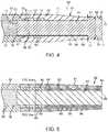
- FIG. 4is a longitudinal section view of the distal section of the liquid core laser ablation catheter embodiment of FIG. 2 which includes a distal optical window embodiment having an insert segment and an expanded segment, a tapered window housing, a catheter body tube, and an optical fluid disposed within the catheter body tube.
- FIG. 5is a longitudinal section view of a distal section of a liquid core laser ablation catheter embodiment which includes an optical window having a constant diameter, a tapered window housing, a catheter body tube, and an optical fluid disposed within the catheter body tube.
- FIG. 6is a transverse section view of the liquid core laser ablation catheter of FIG. 5 .
- FIG. 7is a longitudinal section view of a liquid core laser ablation catheter embodiment distal section which includes an optical window having an insert segment and an expanded segment with a rounded and/or chamfered distal edge, a non-tapered window housing, a catheter body tube, and an optical fluid disposed within the catheter body tube.
- FIG. 8is a transverse section view of the liquid core laser ablation catheter embodiment of FIG. 7 .
- FIG. 9is a longitudinal section view of a liquid core laser ablation catheter embodiment distal section which includes an optical window having an insert segment and an expanded segment with a substantially flat output surface and a rounded distal edge, a tapered metal housing, a catheter body tube, an optical fluid disposed within the catheter body tube, and an eccentric guide wire lumen which is disposed on an exterior surface of the catheter body tube.
- FIG. 10is a transverse section view of the liquid core laser ablation catheter embodiment of FIG. 9 .
- FIG. 11is an elevation view of a fiber optical window embodiment having a constant diameter with a flat polished distal surface with substantially non-rounded edges.
- FIG. 12is an elevation view of an optical window embodiment having an insert segment, an expanded segment, and a substantially flat output surface.
- FIG. 12Ais a transverse section view of the proximal insert segment of the optical window embodiment of FIG. 12 which shows a fiber core and cladding configuration.
- FIG. 12Bis a transverse section view of the expanded segment of the optical window embodiment of FIG. 12 without any cladding layer.
- FIG. 13is an elevation view of an optical window embodiment having an insert segment, an expanded segment, and a substantially convex output surface with rounded edges.
- FIG. 14is an elevation view of an optical window embodiment having an insert segment, an expanded segment, and a substantially concave output surface with rounded edges.
- FIG. 15is an elevation view of a tapered metal window housing embodiment.
- FIG. 16is an elevation view of the tapered window housing embodiment of FIG. 15 and an optical window embodiment having a constant diameter disposed within and secured to the tapered window housing.
- FIG. 17is an elevation view of the tapered window housing embodiment of FIG. 15 and an optical window embodiment having an insert segment and an expanded segment disposed within and secured to the tapered window housing.
- FIG. 18is an elevation view in longitudinal section that shows the liquid core laser ablation catheter embodiment of FIG. 5 cutting through a lesion is a body lumen.
- FIG. 19is an elevation view in longitudinal section of the liquid core laser ablation catheter embodiment of FIG. 4 cutting through a lesion in a body lumen.
- FIG. 20is an elevation view of the liquid core laser ablation catheter of FIG. 19 being advanced into target tissue of the lesion during ablation.
- Laser ablation catheters and laser delivery systemsin general have a wide range of applications in the medical field. Such systems may be used to deliver laser energy to desired sites of a patient's anatomy, and may be particularly suitable for delivering laser energy to locations inside a patient's body that allow for minimally invasive treatment of a variety of indications using a variety of treatment modalities.
- Example of some treatment modalitiesinclude, heating tissue, stimulating tissue, drug activation within a patient's tissue and ablation of tissue or other organic or calcium materials within a patient.
- Some examples of clinical indications for laser treatmentmay include laser atherectomy and the use of a laser catheter to cross total or partial occlusions of body vessels.
- Liquid core laser ablation catheter embodimentsmay generally be considerably less expensive than a silica fiber optic based laser catheter and may also have less dead space at the ablation tip for contact cutting.
- Liquid filled ablation cathetersmay eliminate most of the dead space inside a catheter body tube compared to multiple fiber optic bundles but may still have residual dead space, which consists of the distal fiber window cladding and the outside wall of the metal tip or catheter tube that holds the window.
- Using a tapered metal tipas disclosed for a liquid filled catheter in co-owned patent application number U.S. patent application Ser. No. 13/651,070, Publication No.
- a 5 French liquid filled ablation catheter with a tapered metal tipmay have a 70 percent active area at the tip that gradually reduces to 42 percent once the catheter tip penetrates the target past the tapered metal sheath.
- Multiple fiber optic based catheters, ignoring the guide wire lumen,may have about 17 percent to 30 percent active cutting area in some cases depending on the design at the tip.
- Multiple fiber optic based cathetersmay need to be operated at higher energy fluences and repetition rates compared to fluences and repetition rates of single fiber optic systems or the like in order to cut as efficiently as a laser ablation catheter having a homogenous laser energy output at the output surface of the distal optical window.
- Liquid core laser ablation catheters discussed hereinhave less dead space and needs less energy density to ablate tissue compared generally to multiple fiber optic laser ablation catheter designs currently in commercial use.
- the reduced dead space(that distal surface area that is not emitting laser energy) may be an important feature for ablation of blockages in arteries and for the ability of the laser ablation catheter to cross a lesion in a patient's vessel.
- Some embodiments of liquid core laser ablation cathetersmay incorporate an optical window having an expanded segment with a stepped configuration which is configured to increase the output surface of the liquid core laser ablation catheter, minimize the dead space of the liquid core laser ablation catheter, and allow for easier passage of the liquid core laser ablation catheter through tight lesions which are disposed within the vasculature of a patient with less pulse energy needed.
- a laser ablation systemmay include a laser energy source and a liquid core laser ablation catheter. Some embodiments of the system may also include a laser coupler which is disposed at a proximal section of the liquid core laser ablation catheter.
- the liquid core laser ablation cathetermay include a working length section which is disposed between the proximal section and a distal section of the liquid core laser ablation catheter.
- the working length section of the liquid core laser ablation cathetermay include a catheter body tube which may feature an inner lumen which is disposed within the catheter body tube.
- the inner lumenmay be coated with an optical coating, with the optical coating spanning the working length section.
- An optical fluidmay be disposed within a core liquid volume at least partially bounded by the inner lumen of the catheter body tube, with the optical fluid being in optical communication with the laser coupler.
- the distal section of the liquid core laser ablation cathetermay include a window housing having a tubing cavity which may be secured to the catheter body tube.
- An optical windowmay be partially disposed within and secured to the window housing, in optical communication with the optical fluid.
- the distal optical windowmay include an expanded segment which has an outer radial surface that extends radially beyond an outer radial surface of an insert segment of the optical window, with an outer surface of the insert segment being configured to couple to an interior window surface of the window housing.
- the expanded segmentmay extend distally beyond a distal portion and/or distal end of the window housing.
- the outer diameter of the expanded segmentmay be equal to or greater than an outer diameter of the window housing, thereby allowing optical energy which exits the optical window through an output surface of the expanded segment to ablate a surface area of target material which is greater than or equal to the surface area of the distal section of the liquid core laser ablation catheter.
- the optical window which includes the insert segment and the expanded segmentmay be formed from a single length of ultraviolet grade silica over silica core-clad fiber optic.
- Some liquid core laser ablation catheter embodimentsmay be configured such that optical energy may be transmitted from the laser energy source through the laser coupler, through the optical fluid which disposed within the core liquid volume in the inner lumen of the catheter body tube, through the optical window where it exits the output surface of the expanded segment, and into target tissue and/or target material which is to be ablated by the optical energy.
- the laser energy sourcemay be configured as an ultraviolet laser and the optical energy may be configured as pulsed ultraviolet energy, with each ultraviolet energy pulse having sufficient pulse energy to ablate blockages in body lumens at the distal tip of the liquid core laser ablation catheter when it is curved around typical bends in a patient's vascular system.
- Some laser energy sourcesmay be configured as an XeCl excimer laser with a wavelength around 308 nm, with a pulse duration greater than about 10 nanoseconds (nsec), a pulse energy fluence greater than about 6 milli-Joules per millimeter squared (mJ/mm 2 ) delivered to the distal tip of the liquid core laser ablation catheter and a repetition rate range of about 10 Hertz (Hz) to about 100 Hz.
- nsecnanoseconds
- mJ/mm 2milli-Joules per millimeter squared
- HzHertz
- such laser energy sourcesmay be operated with pulse durations less than about 300 nsec, more specifically, less than about 100 nsec.
- Some distal optical window embodimentsmay be formed monolithically from a single uninterrupted piece of feed fiber optic which is made of ultraviolet grade silica over silica which form a core and cladding of the feed fiber optic.
- the expanded segment of the optical windowmay be formed by melting a portion of the core-cladding materials of the feed fiber optic into a melted portion and forming the expanded segment from the melted portion.
- the portion of the feed fiber optic which has not been meltedmay include the insert portion of the optical window.
- the cladding materialmay be mixed with the core material resulting in an expanded segment of the distal optical window that has no cladding or waveguide configuration, nor does it have any dead space.
- An outer diameter of the expanded segmentmay be larger than an outer radial diameter of the insert segment, and the diameter of the expanded segment may be greater than or equal to diameters of the tip or distal edge of the window housing and/or the catheter body tube proximally adjacent the distal optical window which may have a stepped configuration in some cases.
- the axial length of the expanded segmentmay be configured to be long enough to allow for an optical beam to expand to an outer diameter of the output surface of the expanded segment.
- the length of the expanded segmentmay also be configured to be axially short enough to allow for passage through tortuous pathways within a human patient's anatomical lumen.
- the overall length of the optical windowmay be from about 4 millimeters (mm) to about 8 mm.
- the axial length of the expanded segmentmay be from about 0.5 mm to about 2 mm, more specifically, about 1 mm to about 2 mm in some cases.
- the axial length of the expanded segment 48may be 0.9 mm to 1.1 mm.
- the ratio of the diameter of the expanded segment to the diameter of the insert segmentmay be about from about 1.1:1 to about 1.5:1 in some cases.
- any distal optical window embodiments discussed hereinmay be filleted, rounded or chamfered in order to minimize damage or chipping during assembly, and to prevent trauma to adjacent tissue when disposed within a body lumen.
- the expanded segment and the insert segment of the optical windowmay be monolithically formed from sapphire window material or substrate including a feed fiber optic substrate.
- Some embodiments of optical windows having an expanded segment and an insert segmentmay be formed monolithically from a single piece of material, while other embodiments of optical windows having an expanded segment and an insert segment may be formed by welding or fusing different pieces of material together.
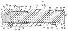
- FIG. 1shows a laser ablation system embodiment 10 that includes a laser energy source 12 having a housing 14 , a power cord 16 , an activation footswitch 18 , a control panel 20 and an output coupler 22 .
- a liquid core laser ablation catheter 24may include a laser coupler 26 which is disposed at a proximal section 28 of the ablation catheter 24 and which may be coupled to the output coupler 22 of the laser source 12 as shown.
- the ablation catheter 24may be disposed within an inner lumen of a support catheter 30 which may be used to guide or support the liquid core laser ablation catheter 24 within a body lumen of a patient.
- the support catheter 30may include a Y-adapter 32 which is coupled to the proximal end 34 of the support catheter 30 .
- the liquid core laser ablation catheter 24may be disposed within and pass through a central lumen (not shown) of the Y-adapter 32 , and a syringe 33 which may contain a normal saline solution that may be used to flush blood and contrast fluid from a distal window 80 of the ablation catheter 24 during ablation procedures.
- the support catheter 30may also incorporate a radiopaque marker 36 which is disposed at a distal section 38 of the support catheter 30 , the radiopaque marker 36 facilitating the visualization of the support catheter 30 when viewed under fluoroscopy.
- a working length 42 of the liquid core laser ablation catheter 24may include the length inside the patient's body between the access point and the target tissue lesion site and the length outside the patient's body necessary to couple or pass through the Y-adapter. An additional length may be needed to couple the working length 42 of 50 centimeters (cm) to 120 cm to the laser source 12 in some cases. If a laser source 12 is large and located away from the patient, an additional working length 42 may be necessary.
- Some liquid core laser ablation catheter embodiments 24may be from about 2 meters to about 3 meters long in some cases.
- the laser source 12 of the laser system 10may include a XeCl excimer laser which produces high energy pulses at a wavelength of about 308 nm, for example, 307 nm to 309 nm, however, other high energy pulsed ultraviolet laser sources may be used.
- Some laser source embodiments 12may have a pulse duration of less than about 100 nsec and a repetition rate of up to about 100 Hz.
- Some such laser source embodiments 12may be capable of producing about 20 milli-Joules per pulse (mJ/pulse) to about 100 mJ/pulse.
- the transmission of laser optical energy through the liquid core laser ablation catheter with solid windowsmay be high enough to enable a relatively small laser source 12 to be used for the laser ablation system 10 in order to save cost and valuable catheter lab space.
- some previous embodiments of ablation catheters having multiple fibersmay have considerable dead space at the input laser coupler, which requires a certain energy density over a larger area and hence requires higher laser optical energy output and a larger more expensive laser source 12 to achieve ablation of the target atheroma.
- the large dead space at the distal end of such ablation catheters having multiple fibersmay require a higher energy fluence in order to overcome the dead space for efficient ablation of atheroma.
- FIG. 2is an enlarged view of the distal section 42 of the liquid core laser ablation catheter 24 which is depicted in FIG. 1 , and of the distal section 38 and radiopaque marker 36 of the support catheter 30 .
- the distal section 60 of the liquid core laser ablation catheter 24may include a distal optical window 44 (see FIG. 12 ) having an insert segment 46 and an expanded segment 48 .
- the distal optical window 44may be partially disposed within a window housing 50 (see FIG. 15 ), the window housing 50 may in turn be secured to a catheter body tube 52 .
- the catheter body tube 52may be fabricated from any suitable polymer material.
- the catheter body tubemay be extruded from a fluorinated ethylene propylene (FEP) fluoropolymer material.
- FEPfluorinated ethylene propylene
- the wall of the catheter body tubemay incorporate a braided material or layer 57 (see FIG. 10 ) which may be disposed within or otherwise encapsulated by the wall material of the catheter body tube 52 .
- the braided materialmay facilitate the torqueablilty and the pushability of the working length 42 of the liquid core laser ablation catheter 24 .
- the window housing 50may include a tapered section 51 as shown in FIG. 2 wherein an outer profile of the window housing 50 is suitably tapered towards the distal end of the window housing 50 .
- the window housing 50may be formed from any suitable high strength polymer or metal material.
- the window housing 50may be fabricated from stainless steel, titanium or other suitable metal that may optionally serve as a radiopaque marker that may be visualized by imaging systems such as a fluoroscopy system.
- An interior lumen 53 of the catheter body tube as shown in FIG. 4may contain an optical fluid 55 , with the optical fluid having an index of refraction (IR) which may depend on the wavelength of the optical energy which is transmitted through the optical fluid 55 .
- IRindex of refraction
- the IR of the optical fluid 55may be about 1.35 to about 1.38 for optical energy which is transmitted at a wavelength of about 308 nm, with the optical fluid 55 being configured to transmit optical energy between the wavelengths of about 306 nm to about 310 nm.
- the optical fluidmay be water or saline.
- the distal section 42 of the liquid core laser ablation catheter 24may be configured to be flexible enough to maneuver around the bends in a patient's vessel without kinking, yet be stiff enough to be able to push the liquid core laser ablation catheter 24 through a patient's body vessel while ablating blockages.
- the optical fluid 55may be sealed within the interior lumen 53 of the catheter body tube 52 by the distal optical window 44 which is disposed in liquid sealed relation to a surface the catheter body tube 52 at a distal end thereof and an input optical window 45 which may be disposed in a liquid sealed relation with a proximal end of the catheter body tube 52 (see FIG. 2A ).
- itmay be an outer surface of the insert segment 46 that is in liquid sealed relation to the inner surface 67 of the catheter body tube 52 .
- an exterior surface 54 of the insert segment 46 of the optical window 44may be bonded to an interior window surface 56 of the window housing 50 using a suitable adhesive 58 as shown in FIG. 17 .
- a distal section 60 of the catheter body tube 52may be notched such that it can be coupled to a tube cavity 62 of the window housing 50 as shown in FIG. 4 .
- a proximal portion 64 of the window housing 50may be crimped to the distal section 60 of the catheter body tube 52 and to a portion of the insert segment 46 of the optical window. The crimped section may act to hermetically seal the interior lumen 53 which contains the optical fluid 55 from the environment which surrounds the liquid core laser ablation catheter 24 .
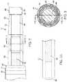
- the window housing 50 , the distal section 62 of the catheter body tube 52 , the insert segment 46 of the distal optical window 44 , and a cladding material 66 which encapsulates the insert segment 46 of the optical window 44are shown in FIG. 3 .
- the expanded segment 48 of the distal optical window 44may extend beyond a distal edge 68 of the window housing 50 as shown in FIG. 4 . In some cases, it may be desirable for a distal edge of the expanded segment 48 to have a rounded or chamfered corner 45 as shown in FIG. 2 .
- a diameter 70 of the expanded segment 48may be greater than or equal to a diameter 72 of the window housing 44 as measured at the distal edge 68 of the window housing 44 in some cases.
- the expanded segment 48 of the distal optical window 44may have an outer diameter or transverse dimension 70 of about 1.1 mm to about 1.3 mm in some cases, in other cases the outer transverse dimension of the expanded segment 48 for such embodiments may be about 1.4 mm to about 1.6 mm.
- the distal optical window 44may have an overall axial length 72 (including the axial length of the insert segment 46 and the expanded segment 48 , see FIG. 12 ) selected to minimize stiffness of the distal section 42 of the liquid core laser ablation catheter 24 but still allow for sufficient beam expansion within the expanded segment 48 so as to fully fill the output surface 80 of the distal optical window 44 with optical energy 89 .
- the distal optical window 44may have an axial length of less than about 10 mm, more specifically, less than about 8 mm, and even more specifically, less than about 6 mm, to allow the distal section 42 of the liquid core laser ablation catheter 24 to negotiate curves in when disposed within a patient's body lumen.
- the axial length of the expanded segment 48may be about 0.5 mm to about 2 mm, and about 1 mm to about 2 mm for some embodiments.
- the ratio of the diameter 70 of the expanded segment 48 to the diameter of the insert segment 46 for a given distal optical window embodiment 44may be about from about 1.1:1 to about 1.5:1 for some embodiments.
- the insert segment 46 of the distal optical window 44which includes a waveguide fiber optic structure which may have a numerical aperture (NA) in the waveguide structure greater than or equal to a NA of the optical fluid 55 in combination with the inner surface 76 of the catheter body tube 52 in order to minimize optical losses at the transition between optical fluid 55 and the distal optical window 44 . That is, the optical fluid 55 disposed within the interior lumen 53 of the catheter body tube 52 forms a waveguide structure in combination with an inner layer or surface 76 of the catheter body tube 52 based on the respective IRs of the optical fluid 55 and inner layer 67 so as to include a waveguide structure for the catheter body tube 52 having an NA that is dependent upon those respective IRs.
- NAnumerical aperture
- a first IR of the inner layer 67is less than a second IR of the optical fluid 55 to produce a waveguide configuration.
- the distal optical window 44may include a high NA optical fiber or a silica rod which is coated with a relatively low numerical index of refraction material such as an amorphous fluoropolymer coating or a dielectric coating that is transparent or reflective of the optical energy laser pulse, which may include an ultraviolet energy pulse.
- FIGS. 13 and 14depict embodiments of the distal optical window 44 with different tip shapes.
- the distal optical window which is depicted in FIGS. 2, 4, and 12features a substantially flat output surface 80 which is disposed at a distal end 81 of the expanded segment 48 .
- FIG. 13depicts a distal optical window embodiment 82 which incorporates a convex output surface 84
- FIG. 14depicts a distal optical window embodiment 86 which incorporates a concave output surface 88 .
- Any liquid core laser ablation catheter embodiment discussed hereinmay incorporate any such distal optical window shape configuration discussed herein.
- the liquid core laser ablation catheter 24may function to ablate target materials or tissue as follows. Referring to FIGS. 1 and 12 , optical energy 89 transmitted from the laser source 12 enters the laser coupler 26 of the liquid core laser ablation catheter and is then transmitted into the optical fluid 55 which is disposed within the interior lumen 53 of the catheter body tube 52 . The optical energy 89 is then transmitted through the optical fluid 55 along the working length 40 of the liquid core laser ablation catheter 24 , with an interior surface 76 of interior lumen 53 of the catheter body tube 52 acting in conjunction with the optical fluid 55 to form a liquid core waveguide.
- the optical energy 89then enters an input surface 78 of the distal optical window 44 , and is transmitted through the insert segment 46 and expanded segment 48 of the distal optical window 44 as shown in FIG. 2 , and then exits the optical window 44 through the output surface 80 of the distal optical window 44 and into target material 90 (see FIG. 19 ).
- the distal optical window 44may be distally advanced into the cavity being formed into the target material 90 as shown in FIG. 20 in order to maintain contact or near contact between the output surface 80 and the target material 90 .
- FIGS. 5, 6 , and 18An embodiment of a liquid core laser ablation catheter 92 that does not include an expanded segment on a distal optical window is shown in FIGS. 5, 6 , and 18 .
- the liquid core laser ablation catheter 92may incorporate a constant diameter distal optical window 94 which is depicted in FIG. 11 .
- the constant diameter distal optical window 94may be bonded into a tapered window housing 50 with an adhesive 58 as shown in FIG. 16 .
- the configurations, dimensions, materials, and functions of elements of the liquid core laser ablation catheter 92may be substantially similar to similar elements of the liquid core laser ablation catheter 24 which has been discussed herein.
- the liquid core laser ablation catheter 92is shown in order to illustrate the improved cutting ability of the liquid core laser ablation catheter embodiments 24 having a distal optical window 44 which incorporates an expanded segment 48 as shown in FIGS. 19 and 20 .
- FIG. 18depicts the liquid core laser ablation catheter 92 disposed within a patient lumen 96 ablating target tissue material 90 with optical energy 89 .
- the optical energy 89exits an output surface 98 of the constant diameter optical window 94 within a first cone angle 100 .
- a hole the size of the optical energy beam 89is created at the output surface 98 of liquid core laser ablation catheter 92 . As shown, this hole may be smaller in transverse dimension than the liquid core laser ablation catheter 92 .
- FIG. 19similarly depicts the liquid core laser ablation catheter 24 disposed within a patient lumen 96 ablating target tissue material 90 with optical energy 89 .
- the optical energy 89exits an output surface 80 of the expanded optical window 44 within a second cone angle 102 .
- the expanded segment 48 of the optical window 44allows the optical energy 89 to diverge prior to exiting the output surface 80 .
- the second cone angle 102 of optical energy 89 produced by liquid core laser ablation catheter 24provides a greater cutting area than the first cone angle 100 of optical energy 89 produced by liquid core laser ablation catheter 92 . This allows the liquid core laser ablation catheter 24 to ablate a hole large enough for the distal section 50 of the liquid core laser ablation catheter 24 to readily follow into the newly created lumen.
- FIGS. 7 and 8depict an embodiment of a liquid core laser ablation catheter 104 which features a non-tapered window housing 106 . That is, an outer diameter 108 of the window housing 106 may be constant along the length of the window housing 106 .
- the liquid core laser ablation catheter 104may incorporate a distal optical window 110 which has an expanded segment 112 having an outer diameter 114 that is equal to or greater than the outer diameter 108 of the window housing 106 .
- the distal edge of the expanded segment 112may have a rounded or chamfered corner 113 in order to facilitate smooth passage of the distal end of the catheter through a patient's vessels.
- the configurations, dimensions, materials, and functions of elements of the liquid core laser ablation catheter 104may be substantially similar to or the same as similar elements of the liquid core laser ablation catheter 24 discussed herein.
- FIGS. 9 and 10depict another embodiment of a liquid core laser ablation catheter 116 that incorporates an eccentric guidewire lumen 118 which is disposed on the periphery or outer surface of the catheter body tube 52 and extends axially along the outer surface of the catheter body tube 52 .
- the guidewire lumen 118is configured to couple to a suitable guidewire, such as a coronary angioplasty type guidewire, thereby allowing for the ablation of eccentric target tissue materials 90 utilizing the liquid core laser ablation catheter 116 .
- a suitable guidewiresuch as a coronary angioplasty type guidewire
- the configurations, dimensions, materials, and functions of elements of the liquid core laser ablation catheter 116may be substantially similar to or the same as similar elements of the liquid core laser ablation catheter 24 which has been previously discussed.
- Pulsed ultraviolet excimer laser ablation catheter embodimentswhich have been discussed herein may be configured to remove various types of atheroma by photochemical, photo-thermal and photo-acoustic processes.
- the irradiated tissuemay be removed with little to no thermal damage to the edges of the lumen wall of the patient, because the nanosecond pulse duration of the ultraviolet pulsed excimer laser currently used for this application is at time scales much less than the thermal diffusion time of the absorbed optical energy.
- the pulsed optical energy from the lasermust be delivered inside the body lumen with a flexible fiber optic or waveguide that can pass the tortuosity of the arterial anatomy of a patient's body to get to the site of the blockage.
- a single fiber opticmight present an efficient cutting surface, but because the catheter size is in the range of 1 mm to 2.5 mm diameter for the ablation surface, these single fibers at this diameter are too stiff for percutaneous use in a patient's body lumen.
- ablation cathetersuse many small diameter fiber optics, typically with cores having diameters of about 50 microns in quantities of about 100 fiber optics to about 300 fiber optics, arranged in a bundle to provide a flexible ablation catheter in a 1 mm to 2.5 mm diameter.
- this cutting surface configurationmay produce a “Swiss cheese” type dead space geometry due to the cladding, packing factor of the multiple fibers, and the outer tube wall thickness. It has been demonstrated that this configuration does not cut as efficiently as a surface with less dead space (such as an ablation catheter which is configured with a single fiber optic) and requires more energy and a higher pulse rate to ablate target tissue.
- an improvement to multiple fiber laser ablation cathetersis the liquid core laser ablation catheter 92 with a solid distal optical window 94 which is disposed at a distal section 60 of the liquid core laser ablation catheter 92 .
- this ablation catheter 92 configurationrequires lower pulsed optical energy to ablate through target material, the ablation hole which is created may be slightly smaller than the outside surface of the ablation catheter 92 in some cases. This may result in resistance to passage of the ablation catheter 92 through target material such as a lesion, especially for a non-compliant lesion such as calcified lesions.
- Laser ablation catheters which incorporate the window housing 50 which includes the tapered section 51may have improved maneuvering through tortuous lesion sites when compared to ablation catheters which do not have tapered window housings. This is due to the fact that laser ablation catheters which incorporate the window housing 50 which includes the tapered section 51 have a reduced profile at the catheter distal section 60 which can more easily pass through tortuous lesion sites within the vasculature of a patient.
- the addition of the distal optical window 44 which incorporates the expanded segment 48 as has been discussedmay further improve the ability of a given laser ablation catheter (such as liquid core laser ablation catheter 24 ) to ablate through target material 90 .
- Optical energy 89 which enters the distal optical window 44may be transmitted through the insert segment 46 of the optical window 44 (where it may be optically contained by a cladding material 66 ) and into the expanded segment 48 , that does not include a cladding layer to serve as a waveguide, where it may diverge and exit the expanded segment 48 through the output surface 80 of the distal optical window 44 .
- the surface area of the output surface 80 of the distal optical window 44may in some cases be greater than or equal to the area of elements which are disposed at the distal section 60 of the respective laser ablation catheter such as the window housing 50 or the catheter body tube 52 .
- Some ablation catheters which utilize the distal optical window 44 having an insert segment 46 and an expanded segment 48may have no dead space at the output surface 80 of the distal optical window 44 .
- a first ablation catheterincorporated a 1 mm diameter distal optical window (constant diameter distal optical window similar to embodiment 92 in FIG. 18 ) and a second ablation catheter incorporated an distal optical window (enlarged head distal optical window similar to embodiment 24 in FIG. 19 ) having an expanded section 48 with a diameter of 1.22 mm.
- the area of the output surface of a given distal optical windowis proportional to the diameter of the distal optical window squared.
- the distal optical window 44 configured with the expanded segment 48 (1.22 mm diameter)produces a 49 percent larger ablation area (output surface 80 ) for the same diameter optic window 94 (1 mm diameter core) with a constant diameter on the same size catheter (5 French).
- the pulse energy from the lasermay need to be increased in order to achieve the appropriate energy fluence over the larger output surface 80 of the expanded segment 48 of the distal optical window 44 .
- the expanded segment 48 of the distal optical window 44may be configured with an output surface 80 which has a surface area which is equal to or greater than a surface area of a cross section of the ablation catheter 24 .
- the distal optical window 44may incorporate an insert segment 46 (typically 5 to 8 mm length for some embodiments) which may be formed from a single length of feed fiber optic.
- the insert segment 46may be disposed within the window housing 50 and/or the catheter body tube 52 of the liquid core laser ablation catheter 52 .
- a proximal portion 59 of the insert segment 46may extend proximally from the interior of the window housing 50 and into the inner lumen 53 of the catheter body tube 52 as shown in FIG. 4 .
- the distal optical window 44may also include expanded segment embodiments 48 having enlarged diameter 70 that is equal to or larger than the distal portion 68 diameter 72 of the ablation catheter 24 .
- the distal optical window 44may be formed from a suitably configured feed fiber optic.
- the expanded segment 48may be formed by melting the cladding material 66 of the feed fiber optic into the inner core of the feed fiber optic within a distal segment of the feed fiber optic, and then shaping the glass within the distal segment into the expanded segment 48 after shaping the entire distal optical window 44 may be annealed to reduce or remove any stress in the material of the distal optical window 44 .
- the distal optical window 44may be secured (using any suitable adhesive for example) into a suitably configured window housing 50 (as shown in FIG. 17 ). The assembly of the distal optical window 44 and window housing 50 may then be secured to a suitably configured catheter body tube 52 .
- the assembly of the distal optical window 44 and window housing 50may be crimped to the catheter body tube 52 onto the insert segment 26 of the distal optical window 44 .
- the optical fluid 55may be disposed within the inner lumen 53 of the catheter body tube 52 .
- An input optical window 45may be inserted into the inner lumen 53 of the proximal end of the catheter body tube 52 in sealed relation to the inside surface of the inner lumen of the catheter body tube 52 .
- the input optical windowmay be made from an ultraviolet grade material such as silica, sapphire or the like that are configured to efficiently transmit ultraviolet optical energy.
- a laser connector 26may then be attached to the proximal section 28 of the liquid core laser ablation catheter 24 .
- the window housing 50may include at least one crimp ridge 67 which may be disposed circumferentially about and extend into the tube cavity 62 of the window housing 50 .
- Each crimp ridge 67may assist in securing the window housing 50 to the catheter body tube 52 after the crimping process.
- Each crimp ridge 67may be configured as an annular protrusion which extends from an inner surface of the crimped portion of the tube cavity 62 of the window housing 50 (see FIG. 4 ) and into the nominal tube cavity 62 .
- the crimp ridge 67 which is depicted in FIG. 4is configured with a radiused profile, however embodiments of crimp ridges 67 may be configured with any suitable profile such as a rectangular profile or a triangular profile.
- multiple crimp ridges 67may be disposed such that they are axially spaced along the interior surface of the tube cavity 62 as shown in FIGS. 15-17 .
- Some embodiments of the window housing 50may be configured with about 1 to about 5 crimp ridges.
- the crimp ridges 67may have an axial spacing of about 0.38 mm to about 0.64 mm. The crimping process which has been previously discussed may result in the penetration of each crimp ridge 67 of a respective window housing 50 into the wall material of the distal section 60 of the catheter body tube 52 as shown in FIG. 4 .
- each crimp ridge 67 into the wall material of the distal section 60 of the catheter body tube 52may result in a mechanical bond between the window housing 50 , the distal optical window 44 , and the catheter body tube 52 .
- the penetration of each crimp ridge 67 into the distal section 60 of the catheter body tube 52may act to prevent relative translational motion between the window housing 50 , the distal optical window 44 , and the catheter body tube 52 .
- Any embodiment of window housings which are discussed hereinmay be configured with at least one crimp ridge 67 .
- the laser coupler 26may be optically coupled to the optical fluid 55 which is disposed within the inner lumen 53 of the catheter body tube 52 .
- the optical fluid 55is in turn optically coupled to the input surface 78 of the distal optical window 44 .
- the input surfacemay in turn be optically coupled to the output surface 80 of the distal optical window 44 by the insert segment 46 and the expanded segment 48 of the distal optical window 44 .
- cladding material 66may be disposed on the outside surface 54 of the insert segment 46 with the cladding material forming a waveguide configuration facilitating the transmission of optical energy 89 through the insert segment 46 .
- the catheter body tube 52may be a fluoropolymer tube.
- the distal end 60 of the fluoropolymer tube 52may be notched to a reduced outer diameter to attach the window housing 50 such that a proximal portion 64 of the window housing 50 matches the outside diameter of the catheter body tube 52 after the window housing 50 has been crimped to the catheter body tube 52 .
- the window housing 50 which secures the distal optical window 44may also act as a radiopaque marker to locate the distal portion 38 of the liquid core laser ablation catheter 24 during a procedure which utilizes x-ray fluoroscopy.
- the typical NA of waveguide functioning portions of distal optical window embodiments 44 formed from ultraviolet transmitting silica over silica fiber opticsmay be about 0.22, thus providing a full cone angle of optical energy 89 of about 25 degrees.
- the NA of the feed fiber within the insert segment 46 of the distal optical window 44may transmit through the expanded segment 48 of the distal optical window 44 .
- the cladding material 66may be removed from the expanded segment 48 of the distal optical window 44 during the formation of the distal optical window 44 .
- the optical energy 89 which is transmitted through the insert segment 46 (which may be configured as an optical feed fiber) of the distal optical window 44expands in a full cone angle into the expanded segment 48 as determined by the numerical aperture of the feed fiber which for some embodiments may include a full cone angle of optical energy 89 of about 25 degrees as shown in FIG. 12 .
- the distribution 91 of the optical energy 89 at the output surface 80 of the distal optical window 44may be somewhat Gaussian (again see FIG. 12 ) with most of the optical energy 89 located in the central region and with lower optical energy at the edges.
- the degree of central concentrationis correlated to the overall length 74 of the expanded segment 48 , because the light may radially expand within the material of the expanded segment 48 by a full cone angle of about 25 degrees in some cases when it enters the expanded segment 48 which may have no cladding material 66 .
- the axial length 74 of expanded segment 48may be minimized in order to maintain catheter tip flexibility, and because there may be no cladding material 66 to contain the optical energy 89 in the expanded segment 48 of the distal optical window 44 .
- optical energy 89may escape from an outer surface 83 of the expanded segment 48 .
- the overall length 74 of this expanded segment 48may thus generally be a compromise between these factors.
- the catheter body tube 52may be attached to the window housing 50 by crimping the proximal portion 64 of the window housing 50 onto a distal portion 60 of the catheter body tube 52 and a respective proximal portion 59 of the distal optical window 44 .
- the distal portion 60 of the catheter body tube 52is crimped to the proximal portion 59 of the distal optical window 44 by the proximal portion 64 of the window housing 50 which may produce a liquid tight seal between the catheter body tube 52 and the distal optical window 44 such that the inner lumen 53 is sealed at the distal end of the catheter body tube 52 by the distal optical window 44 .
- a tube outer surface 61 of the catheter body tube 52may be configured to couple to a housing inner surface 69 of the window housing 50 .
- the outer surface 61 at the distal portion 60may be stepped to a reduced outer diameter such that after crimping the window housing 50 over the distal portion, the transition of the outer surface between the catheter body tube 52 and the window housing 50 is smooth.
- the distal portion 60 of the catheter body tube 52may be bonded into the proximal portion 64 of the window housing 50 with a suitable adhesive 58 such as medical grade class VI epoxy for fiber optics, with the adhesive 58 being disposed between the outer surface 61 of the catheter body tube 52 and housing inner surface 69 .
- an inner lumen of the proximal portion 64 of the window housing 50may be expanded to an inside diameter which is greater than an outside diameter of the distal portion 60 of the catheter body tube 52 in order to facilitate assembly of the device and couple to the distal portion 60 of the catheter body tube 52 .
- the distal portion 60 of the catheter body tube 52may optionally be notched or suitably tapered in order to couple to the proximal portion 64 of the window housing 50 thereto.
- the distal optical window 44configured as a modified fiber optic because a distal optical window which is configured as a bare ultraviolet silica rod would fail optically as a waveguide.
- the adhesive 58 or the window housing 50 inner surfaces ( 56 , 69 ) of the window housing 50would absorb the optical energy 89 configured as ultraviolet light, or any other suitable wavelength range of optical energy, which is transmitted through the distal optical window 44 for such an embodiment, as it would not be refracted from the interface between the distal optical window 44 and the adhesive 58 .
- the axial length 74 of the expanded segment 48 of the distal optical window 44may be only about 1 mm, and the exit angle of the optical energy 89 emitted from the insert segment 46 may have a full cone angle of about 25 degrees into the expanded segment 48 (as shown in FIG. 12 ).
- most of the optical energy 89 for an embodiment with a bare insert segment 46would escape through outer side surfaces the insert segment 46 of the distal optical window 44 which is configured with no cladding material 66 , and would be absorbed by the window housing 50 .
- distal optical window embodiments 44with insert segment embodiments 46 having a silica over silica fiber optic structure with a large numerical aperture.
- Distal optical window embodiments 44 including a large numerical aperture silica over silica fiber optic structuremay produce greater divergence for optical energy 89 being emitted from the core of the insert segment 46 into the material of the expanded segment 48 of the distal optical window 44 .
- a fiber optic structure with a silica over silica core-cladding arrangement for the insert segment 46 with an NA of 0.30yields a cone angle of about 35 degrees for optical energy emitted from the insert segment 46 into the expanded segment 48 that will have improved expansion within the expanded segment 48 of the distal optical window 44 .
- a better match of the respective indices of refraction of the optical fluid 55 and material of the distal optical window 44may also be useful to reduce coupling losses at the interface of two materials with differing indices of refraction.
- the concave output surface 88 of the distal optical window embodimentwhich is depicted in FIG. 14 may act to expand the optical energy 89 emitted from the center of the expanded segment 48 to the edges of the expanded segment 48 , in order to smooth out the Gaussian-like energy distribution 91 such as may be generated from a flat output surface 80 as shown in FIG. 12 .
- the process of crimping the window housing 50 onto the catheter body tube 52 and the distal optical window 44offers improved adhesion strength over some previous embodiments particularly since adhesives do not typically bond well onto fluoropolymers such as Teflon® or FEP.
- the distal optical window 44may be bonded to the window housing 50 as has been previously discussed, and the proximal section 64 of the window housing 50 may be configured to couple to a distal section 60 of the catheter body tube 52 .
- the proximal section 64 of the window housing 50may then be crimped onto the distal section 60 of the catheter body tube 52 and the insertion segment 46 of the distal optical window 44 by any suitable means.
- the crimping processmay be accomplished by a suitably configured crimping machine.
- the compression of the window housing 50 onto the catheter body tube 52 and the insert segment 46 of the distal optical window 44may act to form a hermetic seal between the window housing 50 and the catheter body tube 52 in some cases.
- the crimped configurationparticularly with the use of internal ridges 67 that penetrate an outer wall of the distal section 60 of the catheter body tube 52 , may also improve adhesion strength of the junction between the window housing 50 , the distal optical window 44 and the catheter body tube 52 .
- the strength of this junctionmay in some instances be indicated by destructive pull force testing which may be performed on multiple such assemblies.
- the ridges 67 upon being embedded in the wall material of the distal section 60 of the catheter body tube 52may mechanically capture the distal section 60 to the window housing 50 which may be particularly useful for embodiments using fluoropolymers (such as FEP) for the catheter body tube 52 which may have a very low coefficient of friction and be generally slippery and ill suited for adhesive bonding. Improved adhesion strength may be achieved with the use of a distal optical window embodiment 44 which is formed from a fiber optic.
- fluoropolymerssuch as FEP
- the distal optical window 44 formed from a fiber opticmay be configured with a length which is long enough to achieve a good hermetic seal, but with the overall length 74 of the distal optical window 44 being axially short enough to keep the distal section 60 of the ablation catheter 24 flexible so as to maintain the capability of going through curves in a patient's anatomy such as vascular lumens and the like.
- Embodiments illustratively described hereinsuitably may be practiced in the absence of any element(s) not specifically disclosed herein.
- any of the terms “comprising,” “consisting essentially of,” and “consisting of”may be replaced with either of the other two terms.
- the terms and expressions which have been employedare used as terms of description and not of limitation and use of such terms and expressions do not exclude any equivalents of the features shown and described or portions thereof, and various modifications are possible.
- a or “an”can refer to one of or a plurality of the elements it modifies (e.g., “a reagent” can mean one or more reagents) unless it is contextually clear either one of the elements or more than one of the elements is described.
Landscapes
- Health & Medical Sciences (AREA)
- Surgery (AREA)
- Physics & Mathematics (AREA)
- Life Sciences & Earth Sciences (AREA)
- Biomedical Technology (AREA)
- Heart & Thoracic Surgery (AREA)
- Otolaryngology (AREA)
- Electromagnetism (AREA)
- Optics & Photonics (AREA)
- Engineering & Computer Science (AREA)
- Vascular Medicine (AREA)
- Nuclear Medicine, Radiotherapy & Molecular Imaging (AREA)
- Medical Informatics (AREA)
- Molecular Biology (AREA)
- Animal Behavior & Ethology (AREA)
- General Health & Medical Sciences (AREA)
- Public Health (AREA)
- Veterinary Medicine (AREA)
- Laser Surgery Devices (AREA)
- Media Introduction/Drainage Providing Device (AREA)
Abstract
Description
Claims (23)
Priority Applications (3)
| Application Number | Priority Date | Filing Date | Title |
|---|---|---|---|
| US15/359,412US10555772B2 (en) | 2015-11-23 | 2016-11-22 | Laser ablation catheters having expanded distal tip windows for efficient tissue ablation |
| US16/734,202US11284941B2 (en) | 2015-11-23 | 2020-01-03 | Laser ablation catheters having expanded distal tip windows for efficient tissue ablation |
| US17/677,745US20220175450A1 (en) | 2015-11-23 | 2022-02-22 | Laser ablation catheters having expanded distal tip windows for efficient tissue ablation |
Applications Claiming Priority (2)
| Application Number | Priority Date | Filing Date | Title |
|---|---|---|---|
| US201562258836P | 2015-11-23 | 2015-11-23 | |
| US15/359,412US10555772B2 (en) | 2015-11-23 | 2016-11-22 | Laser ablation catheters having expanded distal tip windows for efficient tissue ablation |
Related Child Applications (1)
| Application Number | Title | Priority Date | Filing Date |
|---|---|---|---|
| US16/734,202ContinuationUS11284941B2 (en) | 2015-11-23 | 2020-01-03 | Laser ablation catheters having expanded distal tip windows for efficient tissue ablation |
Publications (2)
| Publication Number | Publication Date |
|---|---|
| US20170143424A1 US20170143424A1 (en) | 2017-05-25 |
| US10555772B2true US10555772B2 (en) | 2020-02-11 |
Family
ID=58719427
Family Applications (3)
| Application Number | Title | Priority Date | Filing Date |
|---|---|---|---|
| US15/359,412Expired - Fee RelatedUS10555772B2 (en) | 2015-11-23 | 2016-11-22 | Laser ablation catheters having expanded distal tip windows for efficient tissue ablation |
| US16/734,202Active2037-04-18US11284941B2 (en) | 2015-11-23 | 2020-01-03 | Laser ablation catheters having expanded distal tip windows for efficient tissue ablation |
| US17/677,745AbandonedUS20220175450A1 (en) | 2015-11-23 | 2022-02-22 | Laser ablation catheters having expanded distal tip windows for efficient tissue ablation |
Family Applications After (2)
| Application Number | Title | Priority Date | Filing Date |
|---|---|---|---|
| US16/734,202Active2037-04-18US11284941B2 (en) | 2015-11-23 | 2020-01-03 | Laser ablation catheters having expanded distal tip windows for efficient tissue ablation |
| US17/677,745AbandonedUS20220175450A1 (en) | 2015-11-23 | 2022-02-22 | Laser ablation catheters having expanded distal tip windows for efficient tissue ablation |
Country Status (1)
| Country | Link |
|---|---|
| US (3) | US10555772B2 (en) |
Cited By (4)
| Publication number | Priority date | Publication date | Assignee | Title |
|---|---|---|---|---|
| US11020570B2 (en) | 2013-10-16 | 2021-06-01 | Ra Medical Systems, Inc. | Methods and devices for treatment of stenosis of arteriovenous fistula shunts |
| US11123458B2 (en) | 2011-10-14 | 2021-09-21 | Ra Medical Systems, Inc. | Small flexible liquid core catheter for laser ablation in body lumens and methods for use |
| US11147616B2 (en) | 2018-03-22 | 2021-10-19 | Ra Medical Systems, Inc. | Liquid filled ablation catheter with overjacket |
| US11284941B2 (en)* | 2015-11-23 | 2022-03-29 | Ra Medical Systems, Inc. | Laser ablation catheters having expanded distal tip windows for efficient tissue ablation |
Families Citing this family (2)
| Publication number | Priority date | Publication date | Assignee | Title |
|---|---|---|---|---|
| EP3480442A1 (en)* | 2017-11-02 | 2019-05-08 | Siemens Aktiengesellschaft | Optical apparatus |
| WO2025171173A1 (en) | 2024-02-08 | 2025-08-14 | IV-X Medical, LLC | Intravascular lithotripsy system |
Citations (111)
| Publication number | Priority date | Publication date | Assignee | Title |
|---|---|---|---|---|
| US3740113A (en) | 1969-03-13 | 1973-06-19 | Ici Ltd | Light guide |
| US3995934A (en) | 1973-10-19 | 1976-12-07 | Nath Guenther | Flexible light guide |
| US4009382A (en) | 1974-02-11 | 1977-02-22 | Nath Guenther | Flexible light guide, particularly for medical/dental use |
| US4045119A (en) | 1974-08-16 | 1977-08-30 | Laser Bioapplications | Flexible laser waveguide |
| US4380460A (en) | 1981-12-21 | 1983-04-19 | Monsanto Company | Gas separation apparatus |
| US4516972A (en) | 1982-01-28 | 1985-05-14 | Advanced Cardiovascular Systems, Inc. | Guiding catheter and method of manufacture |
| US4530569A (en) | 1981-08-20 | 1985-07-23 | E. I. Du Pont De Nemours And Company | Optical fibers comprising cores clad with amorphous copolymers of perfluoro-2,2-dimethyl-1,3-dioxole |
| US4641912A (en) | 1984-12-07 | 1987-02-10 | Tsvi Goldenberg | Excimer laser delivery system, angioscope and angioplasty system incorporating the delivery system and angioscope |
| US4686979A (en) | 1984-01-09 | 1987-08-18 | The United States Of America As Represented By The United States Department Of Energy | Excimer laser phototherapy for the dissolution of abnormal growth |
| EP0247746A1 (en) | 1986-05-27 | 1987-12-02 | Sumitomo Electric Industries Limited | Laser catheter |
| US4720166A (en) | 1983-06-10 | 1988-01-19 | Daikin Kogyo Co., Ltd. | Cladding materials for optical fibers |
| US4732448A (en) | 1984-12-07 | 1988-03-22 | Advanced Interventional Systems, Inc. | Delivery system for high-energy pulsed ultraviolet laser light |
| US4739768A (en) | 1986-06-02 | 1988-04-26 | Target Therapeutics | Catheter for guide-wire tracking |
| US4747405A (en) | 1984-03-01 | 1988-05-31 | Vaser, Inc. | Angioplasty catheter |
| US4747662A (en) | 1986-05-21 | 1988-05-31 | Hoechst Aktiengesellschaft | Fiber optics having a liquid core and a fluoroplastic cladding |
| US4762129A (en) | 1984-11-23 | 1988-08-09 | Tassilo Bonzel | Dilatation catheter |
| US4770653A (en) | 1987-06-25 | 1988-09-13 | Medilase, Inc. | Laser angioplasty |
| US4784132A (en) | 1983-03-25 | 1988-11-15 | Fox Kenneth R | Method of and apparatus for laser treatment of body lumens |
| US4784135A (en) | 1982-12-09 | 1988-11-15 | International Business Machines Corporation | Far ultraviolet surgical and dental procedures |
| US4793359A (en) | 1987-04-24 | 1988-12-27 | Gv Medical, Inc. | Centering balloon structure for transluminal angioplasty catheter |
| US4799754A (en) | 1985-09-25 | 1989-01-24 | Advanced Interventional Systems, Inc. | Delivery system for high-energy pulsed ultraviolet laser light |
| US4800876A (en) | 1981-12-11 | 1989-01-31 | Fox Kenneth R | Method of and apparatus for laser treatment of body lumens |
| US4834093A (en) | 1986-02-03 | 1989-05-30 | Littleford Phillip O | Dilation catheter and method |
| US4844062A (en) | 1987-10-23 | 1989-07-04 | Spectranetics Corporation | Rotating fiberoptic laser catheter assembly with eccentric lumen |
| US4848336A (en) | 1981-12-11 | 1989-07-18 | Fox Kenneth R | Apparatus for laser treatment of body lumens |
| US4850351A (en) | 1985-05-22 | 1989-07-25 | C. R. Bard, Inc. | Wire guided laser catheter |
| US4862886A (en) | 1985-05-08 | 1989-09-05 | Summit Technology Inc. | Laser angioplasty |
| US4913142A (en) | 1985-03-22 | 1990-04-03 | Massachusetts Institute Of Technology | Catheter for laser angiosurgery |
| US4919508A (en) | 1988-08-04 | 1990-04-24 | The Spectranetics Corporation | Fiberoptic coupler |
| EP0368512A2 (en) | 1988-11-10 | 1990-05-16 | Premier Laser Systems, Inc. | Multiwavelength medical laser system |
| US4927231A (en) | 1988-01-21 | 1990-05-22 | Acculase Inc. | Liquid filled flexible distal tip light guide |
| US4930863A (en) | 1988-05-06 | 1990-06-05 | Rauiot University Authority for Applied Research and Industrial Development Ltd. | Hollow fiber waveguide and method of making same |
| US4998794A (en) | 1989-10-27 | 1991-03-12 | The Spectranetics Corporation | Meniscus lens for coupling an excimer beam into an optical fiber |
| US5005944A (en) | 1987-12-29 | 1991-04-09 | Luxar Corporation | Hollow lightpipe and lightpipe tip using a low refractive index inner layer |
| US5037404A (en) | 1988-11-14 | 1991-08-06 | Cordis Corporation | Catheter having sections of variable torsion characteristics |
| US5040548A (en) | 1989-06-01 | 1991-08-20 | Yock Paul G | Angioplasty mehtod |
| US5041108A (en) | 1981-12-11 | 1991-08-20 | Pillco Limited Partnership | Method for laser treatment of body lumens |
| US5061273A (en) | 1989-06-01 | 1991-10-29 | Yock Paul G | Angioplasty apparatus facilitating rapid exchanges |
| US5076659A (en) | 1988-05-27 | 1991-12-31 | E. I. Du Pont De Nemours And Company | Process for the stabilization of fluoropolymers |
| US5100388A (en) | 1989-09-15 | 1992-03-31 | Interventional Thermodynamics, Inc. | Method and device for thermal ablation of hollow body organs |
| US5165773A (en) | 1990-08-01 | 1992-11-24 | Genther Nath | Flexible light guide having a liquid core and illuminating device including a light guide of this type |
| US5176674A (en) | 1990-03-05 | 1993-01-05 | Schneider (Europe) Ag | Angioplasty light guide catheter for the removal of stenoses using laser light energy |
| US5188632A (en) | 1984-12-07 | 1993-02-23 | Advanced Interventional Systems, Inc. | Guidance and delivery system for high-energy pulsed laser light |
| US5263952A (en) | 1992-03-25 | 1993-11-23 | Spectranetics | Two-piece tip for fiber optic catheter |
| US5267341A (en) | 1991-10-30 | 1993-11-30 | Baxter International Inc. | Fluid catheter with aqueous fluid core and method of use |
| US5290277A (en) | 1992-04-03 | 1994-03-01 | Angeion Corporation | Multi-fiber linear array laser catheter connector |
| EP0590268A1 (en) | 1985-03-22 | 1994-04-06 | Massachusetts Institute Of Technology | Catheter for Laser angiosurgery |
| US5304171A (en) | 1990-10-18 | 1994-04-19 | Gregory Kenton W | Catheter devices and methods for delivering |
| US5321783A (en) | 1992-06-16 | 1994-06-14 | Spectranetics Corporation | Mount for optical fibers |
| US5350395A (en) | 1986-04-15 | 1994-09-27 | Yock Paul G | Angioplasty apparatus facilitating rapid exchanges |
| US5395361A (en) | 1994-06-16 | 1995-03-07 | Pillco Limited Partnership | Expandable fiberoptic catheter and method of intraluminal laser transmission |
| US5412750A (en) | 1993-12-28 | 1995-05-02 | Nath; Guenther | Liquid-core light guide illuminator apparatus |
| WO1995012138A1 (en) | 1993-10-29 | 1995-05-04 | Harold Frederick Eastgate | Liquid core optical waveguide |
| US5419760A (en) | 1993-01-08 | 1995-05-30 | Pdt Systems, Inc. | Medicament dispensing stent for prevention of restenosis of a blood vessel |
| US5429617A (en) | 1993-12-13 | 1995-07-04 | The Spectranetics Corporation | Radiopaque tip marker for alignment of a catheter within a body |
| US5429604A (en) | 1992-03-18 | 1995-07-04 | Spectranetics Corporation | Fiber optic catheter with twistable tip |
| US5456680A (en) | 1993-09-14 | 1995-10-10 | Spectranetics Corp | Fiber optic catheter with shortened guide wire lumen |
| US5484433A (en) | 1993-12-30 | 1996-01-16 | The Spectranetics Corporation | Tissue ablating device having a deflectable ablation area and method of using same |
| US5497441A (en) | 1993-07-09 | 1996-03-05 | Ramot University Authority For Applied Research & Industrial Development Ltd. | Hollow waveguide tips for controlling beam divergence and method of making such tips |
| US5514128A (en) | 1992-08-18 | 1996-05-07 | Spectranetics Corporation | Fiber optic guide wire and support catheter therefor |
| US5573531A (en) | 1994-06-20 | 1996-11-12 | Gregory; Kenton W. | Fluid core laser angioscope |
| WO1997039691A1 (en) | 1996-04-24 | 1997-10-30 | The Regents Of The University Of California | Opto-acoustic transducer for medical applications |
| US5722972A (en) | 1993-08-12 | 1998-03-03 | Power; John A. | Method and apparatus for ablation of atherosclerotic blockage |
| US5737473A (en) | 1995-05-17 | 1998-04-07 | Nath; Guenther | Light guide having a flexible plastic tube filled with an aqueous salt solution |
| WO1998038538A1 (en) | 1997-02-28 | 1998-09-03 | Nath Guenther | New coating materials for liquid lightguides |
| US5836940A (en) | 1994-10-25 | 1998-11-17 | Latis, Inc. | Photoacoustic drug delivery |
| US5868665A (en) | 1996-12-30 | 1999-02-09 | Biggs; Robert C. | Endocoupler system |
| US5989243A (en) | 1984-12-07 | 1999-11-23 | Advanced Interventional Systems, Inc. | Excimer laser angioplasty system |
| US6022309A (en) | 1996-04-24 | 2000-02-08 | The Regents Of The University Of California | Opto-acoustic thrombolysis |
| WO2000030696A1 (en) | 1998-11-20 | 2000-06-02 | Coloplast A/S | A method for sterilising a medical device having a hydrophilic coating |
| US6106510A (en) | 1998-05-28 | 2000-08-22 | Medtronic, Inc. | Extruded guide catheter shaft with bump extrusion soft distal segment |
| US6117128A (en) | 1997-04-30 | 2000-09-12 | Kenton W. Gregory | Energy delivery catheter and method for the use thereof |
| US6143013A (en) | 1995-04-28 | 2000-11-07 | Target Therapeutics, Inc. | High performance braided catheter |
| US6163641A (en) | 1997-01-03 | 2000-12-19 | Eastgate; Harold Frederick | Optical waveguide for UV transmission |
| US6165163A (en) | 1997-09-30 | 2000-12-26 | Target Therapeutics, Inc. | Soft-tip performance braided catheter |
| US6212422B1 (en) | 1993-08-18 | 2001-04-03 | Scimed Life Systems, Inc. | Catheter having a high tensile strength braid wire constraint and method of manufacture |
| US6263236B1 (en) | 1999-11-29 | 2001-07-17 | Illumenex Corporation | Non-occlusive expandable catheter |
| US6368318B1 (en) | 1998-01-23 | 2002-04-09 | The Regents Of The University Of California | Opto-acoustic recanilization delivery system |
| US6418257B1 (en) | 1997-12-15 | 2002-07-09 | Gunther Nath | UVC liquid light guide |
| US6507688B1 (en) | 1997-12-15 | 2003-01-14 | Gunther Nath | Light guide with a liquid core |
| US20030023236A1 (en) | 2001-07-30 | 2003-01-30 | Bio Tex | Cooled tip laser catheter for sensing and ablation of cardiac arrhythmias |
| US6585760B1 (en) | 2000-06-30 | 2003-07-01 | Vascular Architects, Inc | AV fistula and function enhancing method |
| US6609014B1 (en) | 1999-04-14 | 2003-08-19 | Qlt Inc. | Use of PDT to inhibit intimal hyperplasia |
| US20040220473A1 (en) | 2001-03-14 | 2004-11-04 | Allessandro Lualdi | Vascular catheter guide wire carrier |
| US6824553B1 (en) | 1995-04-28 | 2004-11-30 | Target Therapeutics, Inc. | High performance braided catheter |
| CN1652722A (en) | 2002-05-13 | 2005-08-10 | 导管治疗有限公司 | A multi-electrode lead |
| US6963688B2 (en)* | 2003-08-09 | 2005-11-08 | Gunther Nath | Illumination device with light guide and light diffuser |
| US6974473B2 (en) | 2000-06-30 | 2005-12-13 | Vascular Architects, Inc. | Function-enhanced thrombolytic AV fistula and method |
| US7050692B2 (en) | 2002-03-29 | 2006-05-23 | The Spectranetics Corporation | Proximal coupler for optical fibers |
| CN1832708A (en) | 2003-08-08 | 2006-09-13 | 麦迪威公司 | Radio-frequency based catheter system and method for ablating biological tissues |
| US7144381B2 (en) | 2001-06-20 | 2006-12-05 | The Regents Of The University Of California | Hemodialysis system and method |
| US7144248B2 (en) | 2001-10-18 | 2006-12-05 | Irwin Dean S | Device for oral UV photo-therapy |
| US7167622B2 (en) | 2004-04-08 | 2007-01-23 | Omniguide, Inc. | Photonic crystal fibers and medical systems including photonic crystal fibers |
| EP1757428A1 (en) | 2004-06-10 | 2007-02-28 | Pla Giken Co., Ltd. | Catherter molding apparatus |
| US20070244495A1 (en) | 2004-11-22 | 2007-10-18 | Kihong Kwon | Apparatus and method for performing laser-assisted vascular anastomoses using bioglue |
| US7402151B2 (en) | 2004-12-17 | 2008-07-22 | Biocardia, Inc. | Steerable guide catheters and methods for their use |
| US20080249515A1 (en) | 2006-01-27 | 2008-10-09 | The Spectranetics Corporation | Interventional Devices and Methods For Laser Ablation |
| US20090112198A1 (en) | 2007-10-24 | 2009-04-30 | Spectranetics | Liquid light guide catheter having biocompatible liquid light guide medium |
| US20090163899A1 (en) | 2007-12-21 | 2009-06-25 | Spectranetics | Swaged optical fiber catheter tips and methods of making and using |
| US7572254B2 (en) | 2004-09-17 | 2009-08-11 | The Spectranetics Corporation | Apparatus and methods for directional delivery of laser energy |
| WO2009120871A2 (en) | 2008-03-26 | 2009-10-01 | Medical Components, Inc. | Triple lumen catheter |
| US20090254074A1 (en) | 2008-04-02 | 2009-10-08 | Spectranetics | Liquid light-guide catheter with optically diverging tip |
| US20100016842A1 (en) | 2008-07-21 | 2010-01-21 | Spectranetics | Tapered Liquid Light Guide |
| US20100087783A1 (en) | 2008-10-07 | 2010-04-08 | Boston Scientific Scimed, Inc. | Medical devices for delivery of therapeutic agents to body lumens |
| US20100114081A1 (en) | 2008-11-05 | 2010-05-06 | Spectranetics | Biasing laser catheter: monorail design |
| US20100152720A1 (en) | 2008-12-12 | 2010-06-17 | Spectranetics | Offset catheter |
| EP2301617A1 (en) | 2009-09-29 | 2011-03-30 | Biosense Webster, Inc. | Catheter with biased planar deflection |
| US20130096545A1 (en)* | 2011-10-14 | 2013-04-18 | RA Medical Systems | Small flexible liquid core catheter for laser ablation in body lumens and methods for use |
| US8652084B2 (en) | 2007-08-09 | 2014-02-18 | Indiana University Research And Technology Corporation | Arteriovenous shunt with integrated surveillance system |
| US20150105714A1 (en) | 2013-10-16 | 2015-04-16 | Ra Medical Systems, Inc. | Methods and devices for treatment of stenosis of arteriovenous fistula shunts |
| US20170143424A1 (en) | 2015-11-23 | 2017-05-25 | Ra Medical Systems, Inc. | Laser ablation catheters having expanded distal tip windows for efficient tissue ablation |
Family Cites Families (52)
| Publication number | Priority date | Publication date | Assignee | Title |
|---|---|---|---|---|
| US4907133A (en) | 1988-10-26 | 1990-03-06 | Nath Guenther | Illumination device with a light guide of a liquid-filled plastic flexible tube |
| ATE157269T1 (en) | 1990-12-17 | 1997-09-15 | Cardiovascular Imaging Systems | VASCULAR CATHETER HAVING A LOW PROFILE DISTAL END |
| US5374266A (en) | 1991-11-27 | 1994-12-20 | Kabushiki Kaisha Morita Seisakusho | Medical laser treatment device |
| US5438873A (en) | 1993-07-01 | 1995-08-08 | Fiberoptic Sensor Technologies, Inc. | Fiberoptic sensor using tapered and bundled fibers |
| US5496309A (en)* | 1994-05-06 | 1996-03-05 | Trimedyne, Inc. | Catheter device utilizing a laser beam laterally directed by a high index prism in a liquid medium |
| DE4424344A1 (en) | 1994-07-11 | 1996-01-18 | Nath Guenther | High-intensity light, e.g. for irradiating UV-curable adhesive |
| US6423055B1 (en) | 1999-07-14 | 2002-07-23 | Cardiofocus, Inc. | Phototherapeutic wave guide apparatus |
| US5562657A (en)* | 1994-09-19 | 1996-10-08 | Griffin; Stephen E. | Side fire laser catheter method and apparatus |
| DE19508752B4 (en) | 1995-03-10 | 2010-06-02 | Nath, Günther, Dr. | Lighting device with liquid-filled light guide |
| US5843050A (en) | 1995-11-13 | 1998-12-01 | Micro Therapeutics, Inc. | Microcatheter |
| US5833683A (en)* | 1996-01-12 | 1998-11-10 | Surgical Laser Technologies, Inc. | Laterally-emitting laser medical device |
| DE19629706A1 (en) | 1996-07-24 | 1998-01-29 | Guenther Nath | Fluid core light conductor for medical use |
| EP1121558B1 (en) | 1998-10-09 | 2004-01-02 | Günther Nath | Waveguide with hand switch |
| US6520934B1 (en) | 1999-12-29 | 2003-02-18 | Advanced Cardiovascular Systems, Inc. | Catheter assemblies with flexible radiopaque marker |
| US6893427B1 (en) | 2000-03-23 | 2005-05-17 | Vascon, Llc | Catheter with thermoresponsive distal tip portion |
| US6986766B2 (en) | 2001-06-15 | 2006-01-17 | Diomed Inc. | Method of endovenous laser treatment |
| US6796948B2 (en) | 2002-02-21 | 2004-09-28 | Bolton Medical Inc. | Guide wire installation device for catheter |
| US6802838B2 (en)* | 2002-04-22 | 2004-10-12 | Trimedyne, Inc. | Devices and methods for directed, interstitial ablation of tissue |
| US7780715B2 (en) | 2004-03-04 | 2010-08-24 | Y Med, Inc. | Vessel treatment devices |
| US7431467B2 (en) | 2004-05-13 | 2008-10-07 | Gunther Nath | Portable forensic lighting device |
| US9320831B2 (en) | 2005-03-04 | 2016-04-26 | W. L. Gore & Associates, Inc. | Polymer shrink tubes and novel uses therefor |
| US7951092B2 (en) | 2005-05-05 | 2011-05-31 | Abbott Cardiovascular Systems Inc. | Guidewire loader apparatus and method |
| US7909817B2 (en)* | 2005-06-08 | 2011-03-22 | Innovaquartz, Inc. (AMS Research Corporation) | Lateral laser fiber for high average power and peak pulse energy |
| US20080188793A1 (en) | 2007-02-06 | 2008-08-07 | Possis Medical, Inc. | Miniature flexible thrombectomy catheter |
| US7850623B2 (en) | 2005-10-27 | 2010-12-14 | Boston Scientific Scimed, Inc. | Elongate medical device with continuous reinforcement member |
| US20090227997A1 (en) | 2006-01-19 | 2009-09-10 | The Regents Of The University Of Michigan | System and method for photoacoustic imaging and monitoring of laser therapy |
| US20100004607A1 (en) | 2006-07-21 | 2010-01-07 | Scott Wilson | Devices and methods for accessing a cerebral vessel |
| US8574219B2 (en) | 2006-09-18 | 2013-11-05 | Boston Scientific Scimed, Inc. | Catheter shaft including a metallic tapered region |
| US10478251B2 (en) | 2006-12-19 | 2019-11-19 | Srgi Holdings Llc | Steerable and controllable medical laser fibers |
| US9114229B2 (en) | 2006-12-29 | 2015-08-25 | St. Jude Medical, Af Division, Inc. | Dual braid reinforcement deflectable device |
| US20090264898A1 (en) | 2008-04-17 | 2009-10-22 | Medtronic Vascular, Inc. | Steerable Endovascular Retrieval Device |
| EP2361117A4 (en)* | 2008-11-24 | 2012-05-09 | Gradiant Res Llc | Photothermal treatment of soft tissues |
| WO2011062894A2 (en)* | 2009-11-18 | 2011-05-26 | Boston Scientific Scimed, Inc. | Methods and apparatus related to a distal end of a side-fire optical fiber having multiple capillary components |
| EP2501318B1 (en)* | 2009-11-18 | 2020-08-26 | Boston Scientific Scimed, Inc. | Methods and apparatus related to a side -fire member having a doped silica component |
| US20110238041A1 (en) | 2010-03-24 | 2011-09-29 | Chestnut Medical Technologies, Inc. | Variable flexibility catheter |
| US9314304B2 (en)* | 2010-12-08 | 2016-04-19 | Lumicell, Inc. | Methods and system for image guided cell ablation with microscopic resolution |
| WO2012109557A2 (en)* | 2011-02-10 | 2012-08-16 | Dc Devices, Inc. | Apparatus and methods to create and maintain an intra-atrial pressure relief opening |
| US10130789B2 (en) | 2011-06-30 | 2018-11-20 | Covidien Lp | Distal access aspiration guide catheter |
| US20140350401A1 (en)* | 2012-06-30 | 2014-11-27 | Yegor D. Sinelnikov | Carotid body ablation via directed energy |
| US10492876B2 (en) | 2012-09-17 | 2019-12-03 | Omniguide, Inc. | Devices and methods for laser surgery |
| CN105073186B (en)* | 2013-01-31 | 2018-07-10 | 迪格玛医疗有限公司 | Methods and systems for reducing neural activity in an organ of a subject |
| US9283040B2 (en) | 2013-03-13 | 2016-03-15 | The Spectranetics Corporation | Device and method of ablative cutting with helical tip |
| US20150057639A1 (en) | 2013-08-23 | 2015-02-26 | Boston Scientific Scimed, Inc. | Catheters and catheter shafts |
| EP3131490B1 (en)* | 2014-04-17 | 2019-08-07 | Digma Medical Ltd. | Systems for blocking neural activity in the duodenum |
| US11246659B2 (en) | 2014-08-25 | 2022-02-15 | The Spectranetics Corporation | Liquid laser-induced pressure wave emitting catheter sheath |
| US10617847B2 (en) | 2014-11-04 | 2020-04-14 | Orbusneich Medical Pte. Ltd. | Variable flexibility catheter support frame |
| US10926060B2 (en) | 2017-03-02 | 2021-02-23 | Covidien Lp | Flexible tip catheter |
| AU2018366278B2 (en) | 2017-11-10 | 2024-07-04 | Boston Scientific Scimed, Inc. | Medical laser fiber |
| JP2019166289A (en) | 2018-03-22 | 2019-10-03 | ラ メディカル システムズ, インコーポレイテッド | Liquid filled ablation catheter with overjacket |
| US10953195B2 (en) | 2018-06-01 | 2021-03-23 | Covidien Lp | Flexible tip catheter |
| US12239371B2 (en) | 2018-08-09 | 2025-03-04 | Koninklijke Philips N.V. | Treatment mode selection systems and laser catheter systems including same |
| WO2020170176A1 (en) | 2019-02-19 | 2020-08-27 | Asahi Intecc Co. Ltd. | Peripheral vessel tissue modification devices and methods of use thereof |
- 2016
- 2016-11-22USUS15/359,412patent/US10555772B2/ennot_activeExpired - Fee Related
- 2020
- 2020-01-03USUS16/734,202patent/US11284941B2/enactiveActive
- 2022
- 2022-02-22USUS17/677,745patent/US20220175450A1/ennot_activeAbandoned
Patent Citations (126)
| Publication number | Priority date | Publication date | Assignee | Title |
|---|---|---|---|---|
| US3740113A (en) | 1969-03-13 | 1973-06-19 | Ici Ltd | Light guide |
| US3995934A (en) | 1973-10-19 | 1976-12-07 | Nath Guenther | Flexible light guide |
| US4009382A (en) | 1974-02-11 | 1977-02-22 | Nath Guenther | Flexible light guide, particularly for medical/dental use |
| US4045119A (en) | 1974-08-16 | 1977-08-30 | Laser Bioapplications | Flexible laser waveguide |
| US4530569A (en) | 1981-08-20 | 1985-07-23 | E. I. Du Pont De Nemours And Company | Optical fibers comprising cores clad with amorphous copolymers of perfluoro-2,2-dimethyl-1,3-dioxole |
| US4800876B1 (en) | 1981-12-11 | 1991-07-09 | R Fox Kenneth | |
| US4800876A (en) | 1981-12-11 | 1989-01-31 | Fox Kenneth R | Method of and apparatus for laser treatment of body lumens |
| US5041108A (en) | 1981-12-11 | 1991-08-20 | Pillco Limited Partnership | Method for laser treatment of body lumens |
| US4848336A (en) | 1981-12-11 | 1989-07-18 | Fox Kenneth R | Apparatus for laser treatment of body lumens |
| US4380460A (en) | 1981-12-21 | 1983-04-19 | Monsanto Company | Gas separation apparatus |
| US4516972A (en) | 1982-01-28 | 1985-05-14 | Advanced Cardiovascular Systems, Inc. | Guiding catheter and method of manufacture |
| US4784135A (en) | 1982-12-09 | 1988-11-15 | International Business Machines Corporation | Far ultraviolet surgical and dental procedures |
| US4784132B1 (en) | 1983-03-25 | 1990-03-13 | R Fox Kenneth | |
| US4784132A (en) | 1983-03-25 | 1988-11-15 | Fox Kenneth R | Method of and apparatus for laser treatment of body lumens |
| US4720166A (en) | 1983-06-10 | 1988-01-19 | Daikin Kogyo Co., Ltd. | Cladding materials for optical fibers |
| US4686979A (en) | 1984-01-09 | 1987-08-18 | The United States Of America As Represented By The United States Department Of Energy | Excimer laser phototherapy for the dissolution of abnormal growth |
| US4747405A (en) | 1984-03-01 | 1988-05-31 | Vaser, Inc. | Angioplasty catheter |
| US4762129B1 (en) | 1984-11-23 | 1991-07-02 | Tassilo Bonzel | |
| US4762129A (en) | 1984-11-23 | 1988-08-09 | Tassilo Bonzel | Dilatation catheter |
| US4641912A (en) | 1984-12-07 | 1987-02-10 | Tsvi Goldenberg | Excimer laser delivery system, angioscope and angioplasty system incorporating the delivery system and angioscope |
| US5188632A (en) | 1984-12-07 | 1993-02-23 | Advanced Interventional Systems, Inc. | Guidance and delivery system for high-energy pulsed laser light |
| US5989243A (en) | 1984-12-07 | 1999-11-23 | Advanced Interventional Systems, Inc. | Excimer laser angioplasty system |
| US4732448A (en) | 1984-12-07 | 1988-03-22 | Advanced Interventional Systems, Inc. | Delivery system for high-energy pulsed ultraviolet laser light |
| EP0590268A1 (en) | 1985-03-22 | 1994-04-06 | Massachusetts Institute Of Technology | Catheter for Laser angiosurgery |
| US4913142A (en) | 1985-03-22 | 1990-04-03 | Massachusetts Institute Of Technology | Catheter for laser angiosurgery |
| US4862886A (en) | 1985-05-08 | 1989-09-05 | Summit Technology Inc. | Laser angioplasty |
| US4850351A (en) | 1985-05-22 | 1989-07-25 | C. R. Bard, Inc. | Wire guided laser catheter |
| US4799754A (en) | 1985-09-25 | 1989-01-24 | Advanced Interventional Systems, Inc. | Delivery system for high-energy pulsed ultraviolet laser light |
| US4834093A (en) | 1986-02-03 | 1989-05-30 | Littleford Phillip O | Dilation catheter and method |
| US5350395A (en) | 1986-04-15 | 1994-09-27 | Yock Paul G | Angioplasty apparatus facilitating rapid exchanges |
| US4747662A (en) | 1986-05-21 | 1988-05-31 | Hoechst Aktiengesellschaft | Fiber optics having a liquid core and a fluoroplastic cladding |
| EP0247746A1 (en) | 1986-05-27 | 1987-12-02 | Sumitomo Electric Industries Limited | Laser catheter |
| US4739768A (en) | 1986-06-02 | 1988-04-26 | Target Therapeutics | Catheter for guide-wire tracking |
| US4739768B1 (en) | 1986-06-02 | 1994-11-15 | Target Therapeutics Inc | Catheter for guide-wire tracking |
| US4739768B2 (en) | 1986-06-02 | 1995-10-24 | Target Therapeutics Inc | Catheter for guide-wire tracking |
| US4793359A (en) | 1987-04-24 | 1988-12-27 | Gv Medical, Inc. | Centering balloon structure for transluminal angioplasty catheter |
| US4770653A (en) | 1987-06-25 | 1988-09-13 | Medilase, Inc. | Laser angioplasty |
| US4844062A (en) | 1987-10-23 | 1989-07-04 | Spectranetics Corporation | Rotating fiberoptic laser catheter assembly with eccentric lumen |
| US5005944A (en) | 1987-12-29 | 1991-04-09 | Luxar Corporation | Hollow lightpipe and lightpipe tip using a low refractive index inner layer |
| US4927231A (en) | 1988-01-21 | 1990-05-22 | Acculase Inc. | Liquid filled flexible distal tip light guide |
| US4930863A (en) | 1988-05-06 | 1990-06-05 | Rauiot University Authority for Applied Research and Industrial Development Ltd. | Hollow fiber waveguide and method of making same |
| US5076659A (en) | 1988-05-27 | 1991-12-31 | E. I. Du Pont De Nemours And Company | Process for the stabilization of fluoropolymers |
| US5267993A (en) | 1988-08-04 | 1993-12-07 | The Spectranetics Corporation | Fiberoptic coupler |
| US5157750A (en) | 1988-08-04 | 1992-10-20 | The Spectranetics Corporation | Fiberoptic coupler for coupling an optical fiber to a laser light source |
| US4919508A (en) | 1988-08-04 | 1990-04-24 | The Spectranetics Corporation | Fiberoptic coupler |
| EP0368512A2 (en) | 1988-11-10 | 1990-05-16 | Premier Laser Systems, Inc. | Multiwavelength medical laser system |
| US5037404A (en) | 1988-11-14 | 1991-08-06 | Cordis Corporation | Catheter having sections of variable torsion characteristics |
| US5061273A (en) | 1989-06-01 | 1991-10-29 | Yock Paul G | Angioplasty apparatus facilitating rapid exchanges |
| US5040548A (en) | 1989-06-01 | 1991-08-20 | Yock Paul G | Angioplasty mehtod |
| US5100388A (en) | 1989-09-15 | 1992-03-31 | Interventional Thermodynamics, Inc. | Method and device for thermal ablation of hollow body organs |
| US4998794A (en) | 1989-10-27 | 1991-03-12 | The Spectranetics Corporation | Meniscus lens for coupling an excimer beam into an optical fiber |
| US5176674A (en) | 1990-03-05 | 1993-01-05 | Schneider (Europe) Ag | Angioplasty light guide catheter for the removal of stenoses using laser light energy |
| US5165773A (en) | 1990-08-01 | 1992-11-24 | Genther Nath | Flexible light guide having a liquid core and illuminating device including a light guide of this type |
| US5304171A (en) | 1990-10-18 | 1994-04-19 | Gregory Kenton W | Catheter devices and methods for delivering |
| US5267341A (en) | 1991-10-30 | 1993-11-30 | Baxter International Inc. | Fluid catheter with aqueous fluid core and method of use |
| US5429604A (en) | 1992-03-18 | 1995-07-04 | Spectranetics Corporation | Fiber optic catheter with twistable tip |
| US5263952A (en) | 1992-03-25 | 1993-11-23 | Spectranetics | Two-piece tip for fiber optic catheter |
| US5290277A (en) | 1992-04-03 | 1994-03-01 | Angeion Corporation | Multi-fiber linear array laser catheter connector |
| US5321783A (en) | 1992-06-16 | 1994-06-14 | Spectranetics Corporation | Mount for optical fibers |
| US5514128A (en) | 1992-08-18 | 1996-05-07 | Spectranetics Corporation | Fiber optic guide wire and support catheter therefor |
| US5419760A (en) | 1993-01-08 | 1995-05-30 | Pdt Systems, Inc. | Medicament dispensing stent for prevention of restenosis of a blood vessel |
| US5497441A (en) | 1993-07-09 | 1996-03-05 | Ramot University Authority For Applied Research & Industrial Development Ltd. | Hollow waveguide tips for controlling beam divergence and method of making such tips |
| US5722972A (en) | 1993-08-12 | 1998-03-03 | Power; John A. | Method and apparatus for ablation of atherosclerotic blockage |
| US6212422B1 (en) | 1993-08-18 | 2001-04-03 | Scimed Life Systems, Inc. | Catheter having a high tensile strength braid wire constraint and method of manufacture |
| US5456680A (en) | 1993-09-14 | 1995-10-10 | Spectranetics Corp | Fiber optic catheter with shortened guide wire lumen |
| EP0727054A1 (en) | 1993-10-29 | 1996-08-21 | Harold Frederick Eastgate | Liquid core optical waveguide |
| WO1995012138A1 (en) | 1993-10-29 | 1995-05-04 | Harold Frederick Eastgate | Liquid core optical waveguide |
| US5429617A (en) | 1993-12-13 | 1995-07-04 | The Spectranetics Corporation | Radiopaque tip marker for alignment of a catheter within a body |
| US5412750A (en) | 1993-12-28 | 1995-05-02 | Nath; Guenther | Liquid-core light guide illuminator apparatus |
| US5484433A (en) | 1993-12-30 | 1996-01-16 | The Spectranetics Corporation | Tissue ablating device having a deflectable ablation area and method of using same |
| US5395361A (en) | 1994-06-16 | 1995-03-07 | Pillco Limited Partnership | Expandable fiberoptic catheter and method of intraluminal laser transmission |
| US5573531A (en) | 1994-06-20 | 1996-11-12 | Gregory; Kenton W. | Fluid core laser angioscope |
| US5836940A (en) | 1994-10-25 | 1998-11-17 | Latis, Inc. | Photoacoustic drug delivery |
| US6824553B1 (en) | 1995-04-28 | 2004-11-30 | Target Therapeutics, Inc. | High performance braided catheter |
| US6143013A (en) | 1995-04-28 | 2000-11-07 | Target Therapeutics, Inc. | High performance braided catheter |
| US5737473A (en) | 1995-05-17 | 1998-04-07 | Nath; Guenther | Light guide having a flexible plastic tube filled with an aqueous salt solution |
| WO1997039691A1 (en) | 1996-04-24 | 1997-10-30 | The Regents Of The University Of California | Opto-acoustic transducer for medical applications |
| US6022309A (en) | 1996-04-24 | 2000-02-08 | The Regents Of The University Of California | Opto-acoustic thrombolysis |
| US5868665A (en) | 1996-12-30 | 1999-02-09 | Biggs; Robert C. | Endocoupler system |
| US6163641A (en) | 1997-01-03 | 2000-12-19 | Eastgate; Harold Frederick | Optical waveguide for UV transmission |
| US6314226B1 (en) | 1997-02-28 | 2001-11-06 | NATH GüNTHER | Flexible lightguide with a liquid core |
| US6314227B1 (en) | 1997-02-28 | 2001-11-06 | NATH GüNTHER | Coating materials for liquid lightguides |
| WO1998038538A1 (en) | 1997-02-28 | 1998-09-03 | Nath Guenther | New coating materials for liquid lightguides |
| US6117128A (en) | 1997-04-30 | 2000-09-12 | Kenton W. Gregory | Energy delivery catheter and method for the use thereof |
| US6165163A (en) | 1997-09-30 | 2000-12-26 | Target Therapeutics, Inc. | Soft-tip performance braided catheter |
| US6418257B1 (en) | 1997-12-15 | 2002-07-09 | Gunther Nath | UVC liquid light guide |
| US6507688B1 (en) | 1997-12-15 | 2003-01-14 | Gunther Nath | Light guide with a liquid core |
| US6368318B1 (en) | 1998-01-23 | 2002-04-09 | The Regents Of The University Of California | Opto-acoustic recanilization delivery system |
| US6106510A (en) | 1998-05-28 | 2000-08-22 | Medtronic, Inc. | Extruded guide catheter shaft with bump extrusion soft distal segment |
| WO2000030696A1 (en) | 1998-11-20 | 2000-06-02 | Coloplast A/S | A method for sterilising a medical device having a hydrophilic coating |
| US6609014B1 (en) | 1999-04-14 | 2003-08-19 | Qlt Inc. | Use of PDT to inhibit intimal hyperplasia |
| US6263236B1 (en) | 1999-11-29 | 2001-07-17 | Illumenex Corporation | Non-occlusive expandable catheter |
| US6585760B1 (en) | 2000-06-30 | 2003-07-01 | Vascular Architects, Inc | AV fistula and function enhancing method |
| US6974473B2 (en) | 2000-06-30 | 2005-12-13 | Vascular Architects, Inc. | Function-enhanced thrombolytic AV fistula and method |
| US20040220473A1 (en) | 2001-03-14 | 2004-11-04 | Allessandro Lualdi | Vascular catheter guide wire carrier |
| US7144381B2 (en) | 2001-06-20 | 2006-12-05 | The Regents Of The University Of California | Hemodialysis system and method |
| US7762980B2 (en) | 2001-06-20 | 2010-07-27 | Michael Gertner | Hemodialysis access with on-off functionality |
| US20030023236A1 (en) | 2001-07-30 | 2003-01-30 | Bio Tex | Cooled tip laser catheter for sensing and ablation of cardiac arrhythmias |
| US7144248B2 (en) | 2001-10-18 | 2006-12-05 | Irwin Dean S | Device for oral UV photo-therapy |
| US7050692B2 (en) | 2002-03-29 | 2006-05-23 | The Spectranetics Corporation | Proximal coupler for optical fibers |
| CN1652722A (en) | 2002-05-13 | 2005-08-10 | 导管治疗有限公司 | A multi-electrode lead |
| CN1832708A (en) | 2003-08-08 | 2006-09-13 | 麦迪威公司 | Radio-frequency based catheter system and method for ablating biological tissues |
| US6963688B2 (en)* | 2003-08-09 | 2005-11-08 | Gunther Nath | Illumination device with light guide and light diffuser |
| US7167622B2 (en) | 2004-04-08 | 2007-01-23 | Omniguide, Inc. | Photonic crystal fibers and medical systems including photonic crystal fibers |
| EP1757428A1 (en) | 2004-06-10 | 2007-02-28 | Pla Giken Co., Ltd. | Catherter molding apparatus |
| US7572254B2 (en) | 2004-09-17 | 2009-08-11 | The Spectranetics Corporation | Apparatus and methods for directional delivery of laser energy |
| US20070244495A1 (en) | 2004-11-22 | 2007-10-18 | Kihong Kwon | Apparatus and method for performing laser-assisted vascular anastomoses using bioglue |
| US7402151B2 (en) | 2004-12-17 | 2008-07-22 | Biocardia, Inc. | Steerable guide catheters and methods for their use |
| US20080249515A1 (en) | 2006-01-27 | 2008-10-09 | The Spectranetics Corporation | Interventional Devices and Methods For Laser Ablation |
| US8652084B2 (en) | 2007-08-09 | 2014-02-18 | Indiana University Research And Technology Corporation | Arteriovenous shunt with integrated surveillance system |
| US20090112198A1 (en) | 2007-10-24 | 2009-04-30 | Spectranetics | Liquid light guide catheter having biocompatible liquid light guide medium |
| US20090163899A1 (en) | 2007-12-21 | 2009-06-25 | Spectranetics | Swaged optical fiber catheter tips and methods of making and using |
| WO2009120871A2 (en) | 2008-03-26 | 2009-10-01 | Medical Components, Inc. | Triple lumen catheter |
| US20090254074A1 (en) | 2008-04-02 | 2009-10-08 | Spectranetics | Liquid light-guide catheter with optically diverging tip |
| US20100016842A1 (en) | 2008-07-21 | 2010-01-21 | Spectranetics | Tapered Liquid Light Guide |
| US20100087783A1 (en) | 2008-10-07 | 2010-04-08 | Boston Scientific Scimed, Inc. | Medical devices for delivery of therapeutic agents to body lumens |
| US20100114081A1 (en) | 2008-11-05 | 2010-05-06 | Spectranetics | Biasing laser catheter: monorail design |
| US20100152720A1 (en) | 2008-12-12 | 2010-06-17 | Spectranetics | Offset catheter |
| EP2301617A1 (en) | 2009-09-29 | 2011-03-30 | Biosense Webster, Inc. | Catheter with biased planar deflection |
| US20130096545A1 (en)* | 2011-10-14 | 2013-04-18 | RA Medical Systems | Small flexible liquid core catheter for laser ablation in body lumens and methods for use |
| US20170266351A1 (en) | 2011-10-14 | 2017-09-21 | Ra Medical Systems, Inc. | Small flexible liquid core catheter for laser ablation in body lumens and methods for use |
| US20150105714A1 (en) | 2013-10-16 | 2015-04-16 | Ra Medical Systems, Inc. | Methods and devices for treatment of stenosis of arteriovenous fistula shunts |
| US20180021552A1 (en) | 2013-10-16 | 2018-01-25 | Ra Medical Systems, Inc. | Methods and devices for treatment of stenosis of arteriovenous fistula shunts |
| US20180021550A1 (en) | 2013-10-16 | 2018-01-25 | Ra Medical Systems, Inc. | Devices for extended shelf life of liquid core catheters |
| US20180021551A1 (en) | 2013-10-16 | 2018-01-25 | Ra Medical Systems, Inc. | Methods and devices for treatment of stenosis of arteriovenous fistula shunts |
| US20170143424A1 (en) | 2015-11-23 | 2017-05-25 | Ra Medical Systems, Inc. | Laser ablation catheters having expanded distal tip windows for efficient tissue ablation |
Non-Patent Citations (44)
| Title |
|---|
| "Prevalence and Cost of ESRD Therapy," USRDS Annual Data Report 1991, American Journal of Kidney Diseases, vol. 18, No. 5, Suppl 2, (Nov. 1991); pp. 21-29. |
| Bittl; Catheter Interventions for Hemodiaylysis Fistulas and Grafts: J Am Coll Cardiol Intv vol. 3 pp. 1-11 (2010). |
| Das, "Excimer Laser-Assisted Angioplasty for Infrainguinal Artery Disease" J of Endovasc Therapy vol. 16 pp. 1198-11104(2009). |
| Drooz, "Ultrahigh-pressure angioplasty of a transposed brachiocephalic fistula with recurrent stenosis," ConQuest PTA Dilation Catheter, Bard Peripheral Vascular, Innova Fairfax Hospital; Fairfax Virginia, Aug. 2005. |
| ExParte Quayle Action dated: Dec. 12, 2017 in U.S. Appl. No. 14/515,435, filed Oct. 15, 2014, published as: 2015/0105714 on Apr. 16, 2015 and issued as: U.S. Pat. No. 9,962,527 on May 8, 2018. |
| ExParte Quayle Action dated: Nov. 29, 2018 in U.S. Appl. No. 15/723,067, filed Oct. 2, 2017, published as: 2018/0021552 on Jan. 25, 2018. |
| Extended European Search Report dated Aug. 13, 2019 in European Patent Application No. EP 19163464.1, filed: Mar. 18, 2019. |
| Extended European Search Report dated May 29, 2015 in European Patent Application No. EP 12840010.8, filed: Oct. 12, 2012. |
| Final Office Action dated Sep. 15, 2016 in U.S. Appl. No. 13/651,070, filed Oct. 12, 2012 and published as: US-2013/0096545 on: Apr. 18, 2013 and issued as: U.S. Pat. No. 9,700,655 on Jul. 11, 2017. |
| Forauer, Hoffer, et al.; "Dialysis Access Venous Stenoses: Treatment with Balloon Angioplasty-1- versus 3-minute Inflation Times" Radiology vol. 249, pp. 375-381 (2008). |
| Gandini and Del Giudice; "Use of laser Atherectomy with drug-eluting balloon angioplasty shows benefit in treatment of in-stent restenosis" presented at EuroPCR 2014 Congress (May 20-23, 2014) Paris, France. |
| Haage, Verwerk et al.:"Percutaneous treatment of thrombosed primary arteriovenus hemodialysis access fistulae" Kidney International, vol. 57, pp. 1169-1175(2000). |
| Hamburger et al., New Aspects of Excimer Laser Coronary Angioplasty Physical Aspects and Clinical Results, printed by Optima Grafische Communicatie ISBN 90-73235-27-8, Rotterdam, Jaap N. Hamburger, Dec. 1998. |
| Hofstra et al., "Enhanced Cellular Proliferation in Intact Stenotic Lesions Derived From Human Arteriovenous Fistulas and Peripheral Bypass Grafts. Does it correlate with Flow Parameters?" Circulation, 1996;94:1283-1290. |
| International Preliminary Report on Patentability dated Apr. 24, 2014 in International Application No. PCT/US2012/060065 filed Oct. 12, 2012. |
| International Search Report and Written Opinion dated Mar. 29, 2013 in International Application No. PCT/US2012/060065 filed Oct. 12, 2012. |
| Janis et al. "Laser Thrombolysis in an in vitro Model" Lasers in Surg.: Advanced Characterization, Therapeutics and Systems, Pro. of SPIE vol. 3907 pp. 582-585 (2000). |
| Ma et al., "Interaction of excimer laser with blood components and thrombosis" Life Science J. vol. 5 pp. 19-26 (2008). |
| Mickley; "Stenosis and thrombosis in haemodialysis fistulae and grafts: the surgeon's point of view" Nephrol Dial Transplant vol. 19 pp. 309-311 (2004). |
| Miller and Friedman, "Balloon-Assisted Maturation of Arteriovenous Fistulas" Endovascular Today, pp. 46-54 (2010). |
| Morph® "Universal Deflectable Guide Catheter," BioCardia® Cat # 01037-5. |
| Mysliwiec, "Vascular access thrombosis-what are the possibilities of intervention?" Nephrol Dial Transplant (1997) 12: Editorial Comments. |
| Mysliwiec, "Vascular access thrombosis—what are the possibilities of intervention?" Nephrol Dial Transplant (1997) 12: Editorial Comments. |
| Non Final Office Action dated Dec. 31, 2018 in U.S. Appl. No. 15/723,062, filed Oct. 2, 2017, published as: 2018/0021551 on Jan. 25, 2018. |
| Non Final Office Action dated Nov. 30, 2018 in U.S. Appl. No. 15/723,057, filed Oct. 2, 2017, published as: 2018/0021550 on Jan. 25, 2018 and issued as: U.S. Pat. No. 10,245,417 on Apr. 2, 2019. |
| Non-Final Office Action dated Feb. 12, 2016 in U.S. Appl. No. 13/651,070, filed Oct. 12, 2012 and published as: US-2013/0096545 on: Apr. 18, 2013 and issued as: U.S. Pat. No. 9,700,655 on Jul. 11, 2017. |
| Notice of Allowance dated Apr. 17, 2019 in U.S. Appl. No. 15/723,067, filed Oct. 2, 2017, published as: 2018/0021552 on Jan. 25, 2018. |
| Notice of Allowance dated Apr. 19, 2019 in U.S. Appl. No. 15/723,062, filed Oct. 2, 2017, published as: 2018/0021551 on Jan. 25, 2018. |
| Notice of Allowance dated Apr. 20, 2017 in U.S. Appl. No. 13/651,070, filed Oct. 12, 2012 and published as: US-2013/0096545 on: Apr. 18, 2013 and issued as: U.S. Pat. No. 9,700,655 on Jul. 11, 2017. |
| Notice of Allowance dated Dec. 31, 2018 in U.S. Appl. No. 15/723,057, filed Oct. 2, 2017, published as: 2018/0021550 on Jan. 25, 2018 and issued as: U.S. Pat. No. 10,245,417 on Apr. 2, 2019. |
| Notice of Allowance dated Feb. 26, 2019 in U.S. Appl. No. 15/723,057, filed Oct. 2, 2017, published as: 2018/0021550 on Jan. 25, 2018 and issued as: U.S. Pat. No. 10,245,417 on Apr. 2, 2019. |
| Notice of Allowance dated Feb. 27, 2019 in U.S. Appl. No. 15/723,067, filed Oct. 2, 2017, published as: 2018/0021552 on Jan. 25, 2018. |
| Notice of Allowance dated Jan. 30, 2018 in U.S. Appl. No. 14/515,435, filed Oct. 15, 2014, published as: 2015/0105714 on Apr. 16, 2015 and issued as: U.S. Pat. No. 9,962,527 on May 8, 2018. |
| Ozkan, Gungor et al. "Endovascular Stent Placement of Juxtaanastomotic Stenosis in Native Arteriovenus Fistula After Unsuccessful Balloon Angioplasty" Iranian J of Radiology, vol. 10 pp. 133-139 (2013). |
| Papaioannou et al. "Excimer Laser Assisted Thrombolysis: The Effect of Fluence, Repetition Rate and Catheter Size" Proc. SPIE 4609, Lasers in Surgery; Advanced Characterization, Therapeutics and Systems XII 413 (2002). |
| Papaioannou et al. "Particulate debris analysis during excimer laser thrombolysis: An in-vitro study" Proc. SPIE 4609, Lasers in Surgery; Advanced Characterization, Therapeutics and Systems XII 404 (2002). |
| Shenoy, "Surgical anatomy of upper arm: what is needed for AVF planning" J of Vascul Access vol. 10 pp. 223-232(2009). |
| Sofocleous et al.;"Dialysis Fistulas" in Medscape (2013). |
| Staniloae et al. "Obrital Atherectomy: Device Evolution and Clinical Data" Periperal Vasc. Disease, vol. 26,pp. 215-219 (2014). |
| van den Berg, Pedrotti et al.; "In-Stent Restenosis: Mid-Term Results of Debulking Using Excimer Laser and Drug-Eluting Balloons: Sustained Benefit?" J Invasive Cardiol vol. 26 pp. 333-337(2014). |
| van den Berg; "Atherectomy and DCB in the SFA: A Summary of the Data" Endovascular Today pp. 28-32(2014). |
| Walker et al., "Excimer Laser-Assisted Angioplasty" Endovasc. Today ,pp. 75-76 (2007). |
| Zaleski; "Declotting, Maintenance, and Avoiding Procedural Complications of Native Arteriovenus Fistulae" Semin Intervent Radiol. vol. 21, pp. 83-93 (2004). |
| Zwaan et al., "Initial clinical experience with a new pulsed dye laser device in angioplasty of limb ischemia and shunt fistula obstructions," European Journal of Radiology, 14 (1992) pp. 72-76. |
Cited By (7)
| Publication number | Priority date | Publication date | Assignee | Title |
|---|---|---|---|---|
| US11123458B2 (en) | 2011-10-14 | 2021-09-21 | Ra Medical Systems, Inc. | Small flexible liquid core catheter for laser ablation in body lumens and methods for use |
| US11241519B2 (en) | 2011-10-14 | 2022-02-08 | Ra Medical Sysiems, Inc. | Small flexible liquid core catheter for laser ablation in body lumens and methods for use |
| US11020570B2 (en) | 2013-10-16 | 2021-06-01 | Ra Medical Systems, Inc. | Methods and devices for treatment of stenosis of arteriovenous fistula shunts |
| US11730929B2 (en) | 2013-10-16 | 2023-08-22 | Ra Medical Systems, Inc. | Methods and devices for treatment of stenosis of arteriovenous fistula shunts |
| US11284941B2 (en)* | 2015-11-23 | 2022-03-29 | Ra Medical Systems, Inc. | Laser ablation catheters having expanded distal tip windows for efficient tissue ablation |
| US20220175450A1 (en)* | 2015-11-23 | 2022-06-09 | Ra Medical Systems, Inc. | Laser ablation catheters having expanded distal tip windows for efficient tissue ablation |
| US11147616B2 (en) | 2018-03-22 | 2021-10-19 | Ra Medical Systems, Inc. | Liquid filled ablation catheter with overjacket |
Also Published As
| Publication number | Publication date |
|---|---|
| US20200138517A1 (en) | 2020-05-07 |
| US20220175450A1 (en) | 2022-06-09 |
| US11284941B2 (en) | 2022-03-29 |
| US20170143424A1 (en) | 2017-05-25 |
Similar Documents
| Publication | Publication Date | Title |
|---|---|---|
| US11284941B2 (en) | Laser ablation catheters having expanded distal tip windows for efficient tissue ablation | |
| US11241519B2 (en) | Small flexible liquid core catheter for laser ablation in body lumens and methods for use | |
| US11730929B2 (en) | Methods and devices for treatment of stenosis of arteriovenous fistula shunts | |
| US10792103B2 (en) | System for tissue ablation using pulsed laser | |
| US5093877A (en) | Optical fiber lasing apparatus lens | |
| US10716625B2 (en) | Liquid light-guide catheter with optically diverging tip | |
| US10092357B2 (en) | Tapered liquid light guide | |
| US5514128A (en) | Fiber optic guide wire and support catheter therefor | |
| US8647335B2 (en) | Laser applicator | |
| EP0445182A1 (en) | Delivering laser energy | |
| CA2004417A1 (en) | Single axis/angeled beam laser catheter | |
| WO1990005562A1 (en) | Angioplasty catheter with off-axis angled beam delivery fiber | |
| CN113180820A (en) | Radial laser ablation catheter |
Legal Events
| Date | Code | Title | Description |
|---|---|---|---|
| STPP | Information on status: patent application and granting procedure in general | Free format text:DOCKETED NEW CASE - READY FOR EXAMINATION | |
| AS | Assignment | Owner name:RA MEDICAL SYSTEMS, INC., CALIFORNIA Free format text:ASSIGNMENT OF ASSIGNORS INTEREST;ASSIGNORS:LAUDENSLAGER, JAMES B.;IRWIN, DEAN S.;REEL/FRAME:045415/0067 Effective date:20180123 | |
| AS | Assignment | Owner name:RA MEDICAL SYSTEMS, INC. (A DELAWARE CORPORATION), CALIFORNIA Free format text:MERGER;ASSIGNOR:RA MEDICAL SYSTEMS, INC. (A CALIFORNIA CORPORATION);REEL/FRAME:046475/0442 Effective date:20180711 Owner name:RA MEDICAL SYSTEMS, INC. (A DELAWARE CORPORATION), Free format text:MERGER;ASSIGNOR:RA MEDICAL SYSTEMS, INC. (A CALIFORNIA CORPORATION);REEL/FRAME:046475/0442 Effective date:20180711 | |
| STPP | Information on status: patent application and granting procedure in general | Free format text:NON FINAL ACTION MAILED | |
| STPP | Information on status: patent application and granting procedure in general | Free format text:RESPONSE TO NON-FINAL OFFICE ACTION ENTERED AND FORWARDED TO EXAMINER | |
| STPP | Information on status: patent application and granting procedure in general | Free format text:NOTICE OF ALLOWANCE MAILED -- APPLICATION RECEIVED IN OFFICE OF PUBLICATIONS | |
| STPP | Information on status: patent application and granting procedure in general | Free format text:PUBLICATIONS -- ISSUE FEE PAYMENT RECEIVED | |
| STCF | Information on status: patent grant | Free format text:PATENTED CASE | |
| FEPP | Fee payment procedure | Free format text:MAINTENANCE FEE REMINDER MAILED (ORIGINAL EVENT CODE: REM.); ENTITY STATUS OF PATENT OWNER: SMALL ENTITY | |
| LAPS | Lapse for failure to pay maintenance fees | Free format text:PATENT EXPIRED FOR FAILURE TO PAY MAINTENANCE FEES (ORIGINAL EVENT CODE: EXP.); ENTITY STATUS OF PATENT OWNER: SMALL ENTITY | |
| STCH | Information on status: patent discontinuation | Free format text:PATENT EXPIRED DUE TO NONPAYMENT OF MAINTENANCE FEES UNDER 37 CFR 1.362 | |
| FP | Lapsed due to failure to pay maintenance fee | Effective date:20240211 |