US10555763B2 - Dynamic cervical plate - Google Patents
Dynamic cervical plateDownload PDFInfo
- Publication number
- US10555763B2 US10555763B2US14/976,721US201514976721AUS10555763B2US 10555763 B2US10555763 B2US 10555763B2US 201514976721 AUS201514976721 AUS 201514976721AUS 10555763 B2US10555763 B2US 10555763B2
- Authority
- US
- United States
- Prior art keywords
- prong
- bearing member
- members
- ramp
- spinal implant
- Prior art date
- Legal status (The legal status is an assumption and is not a legal conclusion. Google has not performed a legal analysis and makes no representation as to the accuracy of the status listed.)
- Expired - Fee Related, expires
Links
Images


Classifications
- A—HUMAN NECESSITIES
- A61—MEDICAL OR VETERINARY SCIENCE; HYGIENE
- A61B—DIAGNOSIS; SURGERY; IDENTIFICATION
- A61B17/00—Surgical instruments, devices or methods
- A61B17/56—Surgical instruments or methods for treatment of bones or joints; Devices specially adapted therefor
- A61B17/58—Surgical instruments or methods for treatment of bones or joints; Devices specially adapted therefor for osteosynthesis, e.g. bone plates, screws or setting implements
- A61B17/68—Internal fixation devices, including fasteners and spinal fixators, even if a part thereof projects from the skin
- A61B17/80—Cortical plates, i.e. bone plates; Instruments for holding or positioning cortical plates, or for compressing bones attached to cortical plates
- A61B17/8023—Variable length plates adjustable in both directions
- A—HUMAN NECESSITIES
- A61—MEDICAL OR VETERINARY SCIENCE; HYGIENE
- A61B—DIAGNOSIS; SURGERY; IDENTIFICATION
- A61B17/00—Surgical instruments, devices or methods
- A61B17/56—Surgical instruments or methods for treatment of bones or joints; Devices specially adapted therefor
- A61B17/58—Surgical instruments or methods for treatment of bones or joints; Devices specially adapted therefor for osteosynthesis, e.g. bone plates, screws or setting implements
- A61B17/68—Internal fixation devices, including fasteners and spinal fixators, even if a part thereof projects from the skin
- A61B17/70—Spinal positioners or stabilisers, e.g. stabilisers comprising fluid filler in an implant
- A61B17/7059—Cortical plates
- A—HUMAN NECESSITIES
- A61—MEDICAL OR VETERINARY SCIENCE; HYGIENE
- A61B—DIAGNOSIS; SURGERY; IDENTIFICATION
- A61B17/00—Surgical instruments, devices or methods
- A61B17/56—Surgical instruments or methods for treatment of bones or joints; Devices specially adapted therefor
- A61B17/58—Surgical instruments or methods for treatment of bones or joints; Devices specially adapted therefor for osteosynthesis, e.g. bone plates, screws or setting implements
- A61B17/68—Internal fixation devices, including fasteners and spinal fixators, even if a part thereof projects from the skin
- A61B17/80—Cortical plates, i.e. bone plates; Instruments for holding or positioning cortical plates, or for compressing bones attached to cortical plates
- A61B17/8004—Cortical plates, i.e. bone plates; Instruments for holding or positioning cortical plates, or for compressing bones attached to cortical plates with means for distracting or compressing the bone or bones
- A—HUMAN NECESSITIES
- A61—MEDICAL OR VETERINARY SCIENCE; HYGIENE
- A61B—DIAGNOSIS; SURGERY; IDENTIFICATION
- A61B17/00—Surgical instruments, devices or methods
- A61B17/56—Surgical instruments or methods for treatment of bones or joints; Devices specially adapted therefor
- A61B17/58—Surgical instruments or methods for treatment of bones or joints; Devices specially adapted therefor for osteosynthesis, e.g. bone plates, screws or setting implements
- A61B17/88—Osteosynthesis instruments; Methods or means for implanting or extracting internal or external fixation devices
- A—HUMAN NECESSITIES
- A61—MEDICAL OR VETERINARY SCIENCE; HYGIENE
- A61B—DIAGNOSIS; SURGERY; IDENTIFICATION
- A61B17/00—Surgical instruments, devices or methods
- A61B17/56—Surgical instruments or methods for treatment of bones or joints; Devices specially adapted therefor
- A61B17/58—Surgical instruments or methods for treatment of bones or joints; Devices specially adapted therefor for osteosynthesis, e.g. bone plates, screws or setting implements
- A61B17/68—Internal fixation devices, including fasteners and spinal fixators, even if a part thereof projects from the skin
- A61B17/80—Cortical plates, i.e. bone plates; Instruments for holding or positioning cortical plates, or for compressing bones attached to cortical plates
- A61B17/8004—Cortical plates, i.e. bone plates; Instruments for holding or positioning cortical plates, or for compressing bones attached to cortical plates with means for distracting or compressing the bone or bones
- A61B17/8009—Cortical plates, i.e. bone plates; Instruments for holding or positioning cortical plates, or for compressing bones attached to cortical plates with means for distracting or compressing the bone or bones the plate having a ratchet
Definitions
- the present inventionrelates to a bone plate, and more particularly it relates to such a dynamic bone plate for use in spine.
- Spinal fixation platescan be used for a variety of conditions, including for example, providing added strength and rigidity after fusion of adjacent vertebral bodies for securing vertebrae together where an intervening vertebral body has been removed and replaced.
- a spinal fixation plateis applied to the anterior side of affected vertebrae to span at least one affected disc space.
- a spinal fixation platemay be applied to adjacent vertebral bodies where at least a portion of a disc has been removed and a spinal fusion spacer has been inserted.
- a spinal platemay be attached to the anterior of two or more vertebral bodies for the purpose of immobilizing, stabilizing, and/or aligning those vertebrae. Additionally, such a plate may be used, for example, to supplement the function of an intervertebral spacer or artificial disc, to prevent an intervertebral spacer from being expelled from an intervertebral disc space and/or to act as a support for biocompatible bone graft material that is implanted in the disc space.
- Orthopedic fixation devicessuch as spinal plates may be coupled to bone with fasteners inserted through openings in the plates.
- the fastenersmay or may not be secured to the plate. It is known to secure such fasteners to a bone plate, for example, through the use of threads on the fastener and matching threads on the plate, though other means of securement are available. Such a screw-plate interface may decrease the incidence of loosening of the fixation assembly post-operatively. It is also known that a bushing may preferably be disposed in each plate hole to receive the fastener to permit polyaxial movement so that the fastener may be angulated at a surgeon-selected angle.
- each opening in the platepreferably has a groove or recess for receiving a split ring, though any other suitable screw locking systems may be used in connection with the present invention.
- Split ringsmay be pre-assembled to the bone plate.
- a split-ringcan be sized to expand upon insertion of a bone screw into an opening in the bone plate. Once the head of the screw has passed through the split ring, the split ring can contract under its natural spring tension. When the ring relaxes to its unexpanded state, it prevents the bone screw from backing out of the plate by the engagement of an undersurface of the split-ring and an upwardly facing surface on the bone screw.
- U.S. Pat. No. 6,602,255, titled “BONE SCREW RETAINING SYSTEM” and issued on Aug. 5, 2003 and U.S. Pat. No. 6,261,291, titled “Orthopedic Implant Assembly” and issued on Jul. 17, 2001both disclose devices used for securing bone screws to a bone plate and are incorporated herein by reference in their entirety as if fully set forth herein.
- a spinal platewhich may be adjustable along the longitudinal axis between a plurality of positions.
- These platesmay generally be described as incremental locking plates that are not infinitely adjustable.
- Such platesonly allow for a first plate and a second plate to be assembled in a finite number of fixed positions with respect to one another by a surgeon or through natural subsidence after implantation.
- many of the platescannot be extended once locked in a fixed position, and this restricts flexibility during surgery and in revisions.
- Such a fixation systempreferably includes plates that may freely subside in a first direction, while preventing movement of the plates in a second direction, as well as having the ability to unlock so that the plates can move in the second direction if desirable or necessary.
- Such a platepreferably provides the desired support to the vertebrae to be fused, and allows compression of the vertebrae with respect to at least a portion of the plate, thereby limiting the undesirable effects of load shielding by the plate due to graft subsidence caused by settling or normal forces experienced in the spinal column.
- a first aspect of the present inventionis a dynamic subsidence device.
- the dynamic subsidence devicecomprises a first member, a second member contacting the first member, the first and second members being moveable with respect to one another.
- the devicefurther includes a ramp portion on the first member, an interference portion on the second member, and a bearing member situated between the ramp portion of the first member and the interference portion of the second member.
- the ramp portionmay be adapted to the second member, and the interference portion may be adapted to the first member.
- the bearing memberpermits movement of the first member with respect to the second member in a first direction in an infinite number of positions between a first assembled position and a second assembled position.
- the bearing memberprevents movement of the first member with respect to the second member in a second direction between the first and second assembled positions.
- the ramp portion of the first memberis preferably a curved ramp.
- the first membermay further include at least one vertical slot.
- the second memberfurther includes at least two apertures, wherein the first and second member are prevented from disengaging when the vertical slot of the first member is situated between the at least two apertures and a pin is placed through the at least two apertures of the second member and the vertical slot of the first member.
- the second membermay include at least one vertical slot and the first member may include at least two apertures wherein the first and second member are prevented from disengaging when the vertical slot of the second member is situated between the at least two apertures and a pin is placed through the at least two apertures of the first member and the vertical slot of the second member.
- the function of the vertical slot in the plate systemis to aid in limiting the translation of the first and second members with respect to one another between the first and second assembled position. Further, the function of at least one of the at least two apertures in the plate system is to secure the pin member therein.
- the pinis configured to slidably engage the slot of the first or second member.
- the structure of the slot and pin configuration of the plate systemfunctions to add further security to the slidable engagement of the first and second members with respect to one another.
- the first memberincludes at least one opening for receiving a fastener therein for attaching the first member to a vertebral body of the spine.
- the second memberfurther includes at least one opening for receiving a fastener therein for attaching the second member to a vertebral body of the spine.
- the openings in the first and second members adapted to receive fasteners thereinpreferably include a groove or recess for receiving a split ring therein.
- each split ring adapted to an openingis configured to prevent a fastener from backing out of the first and second members by the engagement of an undersurface of the split ring and an upwardly facing surface on the fastener.
- the first membermay further include a first prong and a second prong, the first prong having a male portion and a receiving portion, the second prong including the ramp portion.
- the second membermay further include a first prong and a second prong, the first prong having a female portion configured to receive the male portion of the first prong of the first member and a guidance portion configured to engage the receiving portion of the first prong of the first member, the second prong of the second member including the interference portion.
- the bearing memberis freely seated between the ramp portion and the interference portion of the lock assembly associated with the first and second plate members when the first and second members are in the first assembled position. Further, the bearing member is preferably freely seated between the ramp portion and the interference portion of the lock assembly when the first member is moving with respect to the second member in a first direction. Alternatively, the bearing member preferably locks between the ramp portion and the interference portion of the lock assembly when the first member is moving with respect to the second member in an opposite second direction thereby impeding the translation of the plates in the second direction.
- the bearing membermay return to the portion of the ramp portion where it is freely seated between the ramp portion and the interference portion. In this position, the bearing member may rotate freely and the first and second members may subside again while moving in the first direction.
- the lock assemblypreferably includes a keyhole configured to allow an instrument to enter a space between the ramp portion and the interference portion and hold the bearing member in place, thus releasing the bearing member locked between the ramp portion and the interference portion.
- the instrumentis configured to impart a force on the bearing member sufficient to overcome the frictional forces on the bearing member while locked between the ramp portion and the interference portion.
- the instrumentis further configured to move the bearing member back towards the deeper part of the ramp portion where the bearing member may freely rotate.
- a second aspect of the present inventionis a dynamic subsidence plate for the cervical vertebrae of the spine.
- the dynamic subsidence platecomprises a first member having a protruding end including a ramp portion, a second member having a receiving end configured to slidably receive the protruding end of the first member, the receiving end of the second member including an interference portion, and a bearing member situated between the ramp portion of the first member and the interference portion of the second member.
- the bearing memberis preferably configured to allow movement of the first member with respect to the second member in a first direction in an infinite number of positions between a first assembled position and a second assembled position.
- the bearing memberis further configured to prevent movement of the first member with respect to the second member in an opposite second direction between the first and second assembled positions.
- a third aspect of the present inventionis a dynamic subsidence plate for the cervical vertebrae of the spine.
- the dynamic subsidence platecomprises a first member having a first prong and a second prong, the first prong having a male portion and a receiving portion, the second prong having a ramp portion.
- the platepreferably further comprises a second member for receiving the first member, the second member having a first prong and a second prong, the first prong having a female portion configured to receive the male portion of the first prong of the first member and a guidance portion configured to engage the receiving portion of the first prong of the first member, the second prong of the second member having an interference portion.
- the platefurther comprises a bearing member freely seated between the ramp portion of the second prong of the first member and the interference portion of the second prong of the second member when the first member is moving with respect to the second member in a first direction and alternatively locked between the ramp portion of the second prong of the first member and the interference portion of the second prong of the second member when the first member is moving with respect to the second member in an opposite second direction.
- a bearing memberfreely seated between the ramp portion of the second prong of the first member and the interference portion of the second prong of the second member when the first member is moving with respect to the second member in a first direction and alternatively locked between the ramp portion of the second prong of the first member and the interference portion of the second prong of the second member when the first member is moving with respect to the second member in an opposite second direction.
- An exemplary method of providing dynamic subsidence between a first and second body with the plate device of the present inventionincludes slidably engaging the first and second plate members together and maintaining the first and second plate members in a first assembled position. The method including fastening the first member to the first body and the second member to the second body and allowing the first and second plate members to subside in a first direction in an infinite number of positions between the first assembled position and a second assembled position, wherein the first body and the second body are closer together when the plate device is in the second assembled position.
- the plate devicefurther includes a lock assembly having a ramp portion, an interference portion, and a bearing member, wherein the bearing member is located in a deeper portion of the ramp portion when the plate device is in the first assembled position.
- the bearingis lodged between the ramp portion and the interference portion of the lock assembly when the plate is in the second assembled position, the bearing preventing the first and second plate members from subsiding further in the first direction.
- the methodmay further include inserting an instrument between the ramp portion and the interference portion such that the instrument may be used to release the lodged bearing.
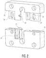
- FIG. 1is an exploded front view of a dynamic subsidence plate according to a first embodiment of the present invention.
- FIG. 2is an exploded rear view of the dynamic subsidence plate of FIG. 1 .
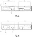
- FIG. 3is a top view of the second member of the dynamic subsidence plate of FIG. 1 .
- FIG. 4is a top view of the second member of the dynamic subsidence plate of FIG. 1 .
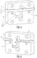
- FIG. 5is a front assembled view of an exemplary embodiment of a first member, a second member, and a clip, the clip used to maintain the first member and the second member in a first assembled position.
- FIG. 6is a back assembled view of the assembly of FIG. 5 .
- FIG. 7is a front assembled view of the plate of FIG. 1 showing the vertical slot of the first member situated between the at least two apertures of the second member and a pin placed through the at least two apertures of the second member and the vertical slot of the first member.
- FIG. 8is a back assembled view of the plate of FIG. 1 showing an instrument inserted into the keyhole of the first member.
- FIG. 9is a cross-sectional view taken along line 3 - 3 of the lock assembly of the dynamic subsidence plate of FIG. 1 when the first member and the second member are in an exemplary first assembled position.
- FIG. 10is a cross-sectional view taken along line 4 - 4 of the lock assembly of the dynamic subsidence plate of FIG. 1 when the first member and the second member are in a locked position.
- FIG. 11is a cross-sectional view taken along line 5 - 5 of the lock assembly of the dynamic subsidence plate of FIG. 1 when the first member and the second member are in an exemplary second assembled position.
- FIG. 12is a cross-sectional view of an alternative dynamic subsidence plate showing the ramp portion of the lock assembly when the first member and the second member are in an exemplary first assembled position, the ramp portion shown as an inclined plane.
- FIG. 13is a cross-sectional view of the plate of FIG. 12 showing the ramp portion of the lock assembly when the first member and the second member are in a locked position, the ramp portion shown as an inclined plane.
- FIG. 14is a cross-sectional view of the plate of FIG. 12 showing the lock assembly when the first member and the second member are in an exemplary second assembled position, the ramp portion shown as an inclined plane.
- proximalmeans closer to the heart and the term “distal” means more distant from the heart.
- distalmeans more distant from the heart.
- inferiormeans lower or bottom and the term “superior” means upper or top.
- anteriormeans towards the front part of the body or the face and the term “posterior” means towards the back of the body.
- medialmeans toward the midline of the body and the term “lateral” means away from the midline of the body.
- FIGS. 1-11an embodiment of the dynamic cervical plate of the present invention designated generally by reference numeral 10 .
- plate 10includes a first plate member 12 , a second plate member 14 , and a lock assembly 16 .
- first member 12 and second member 14are slidably engagable.
- lock assembly 16includes a ramp portion 18 on first member 12 , an interference portion 20 on second member 14 , and a bearing member 19 situated between ramp portion 18 of first member 12 and interference portion 20 of second member 14 .
- ramp portion 18may be adapted to second member 14 and interference portion 20 may be adapted to first member 12 .
- ramp portion 18is either an inclined plane or a curved ramp, while it is contemplated ramp portion 18 may be other geometric or non-geometric configurations.
- lock assembly 16is configured to allow movement of first member 12 with respect to second member 14 in a first direction in an infinite number of positions between a first assembled position and a second assembled position.
- lock assembly 16substantially prevents movement of first member 12 with respect to second member 14 in an opposite second direction between the first and second assembled positions.
- first member 12includes a mating surface 22 configured to substantially engage a mating surface 24 of second member 14 .
- the sliding engagement of first member 12 and second member 14 in the first directioncan no longer occur after surfaces 22 , 24 mate.
- first member 12 and second member 14are in sliding engagement.
- bearing member 19is preferably freely seated between ramp portion 18 and interference portion 20 in the first assembled position.
- a surgeonpreoperatively decides the amount of subsidence between first member 12 and second member 14 of plate 10 that is needed for a particular patient.
- plate 10is generally configured to subside 1 mm to 10 mm.
- surface 22 of first member 12 and surface 24 of second member 14are slidably engaged and distanced approximately 1 mm to 4 mm apart in the first assembled position.
- a surgeonmay decide based on the type of operation performed or the particular patient's anatomy and/or deformity to have surface 22 of first member 12 and surface 24 of second member 14 in the first assembled position at a greater distance than 4 mm.
- the second assembled positionis defined as the position where sliding engagement of first member 12 and second member 14 in the first direction is prevented, generally, after surfaces 24 , 26 mate.
- first member 12may translate freely with respect to second member 14 in a first direction D 1 without engaging lock assembly 16 .
- lock assembly 16is configured to allow first member 12 and second member 14 to slide freely with respect to one another in first direction D 1 .
- first direction D 1is a downward direction as surface 22 of first member 12 translates toward second member 14 . Movement in the first direction may only occur for first member 12 if second member 14 is in a fixed position.
- first and second members 12 , 14will generally both translate with respect to one another as subsidence occurs. Therefore, first member 12 and second member 14 both generally define movement in first direction D 1 and second direction D 2 . It is also contemplated that the present invention is applicable to implants other than plates and further, other than plates moving in directly opposite directions.
- lock assembly 16preferably provides a locking mechanism to allow movement or translation of members 12 , 14 freely in first direction D 1 , while preventing backward movement or translation of members 12 , 14 in reference to one another in second direction D 2 .
- bearing member 19is located in the deeper part of ramp portion 18 when first member 12 and second member 14 are in sliding engagement at an exemplary first assembled or at rest position as shown in FIG. 9 .
- bearing member 19is preferably static and will rotate in place in the deeper area of the pocket. As shown in FIG. 10 , if first member 12 and second member 14 begin to move or translate in opposite second direction D 2 and members 12 , 14 therefore start to pull apart, bearing member 19 will be forced to rotate up ramp portion 18 due to the friction created between ramp portion 18 and interference portion 20 of members 12 , 14 .
- bearing member 19will rotate up ramp portion 18 until the amount of point loading of bearing member 19 with respect to ramp portion 18 and interference portion 20 of members 12 , 14 is sufficient enough to stop the movement or translation of members 12 , 14 in second direction D 2 .
- this point loadingoccurs instantaneously as the movement of members 12 , 14 change from first direction D 1 to second direction D 2 .
- lock assembly 16is further configured such that if first member 12 and second member 14 have stopped moving apart in direction D 2 , and start moving towards each other again in direction D 1 , bearing member 19 may go back down ramp portion 18 , thus releasing lock assembly 16 .
- ramp portion 18 , interference portion 20 , and the size of bearing 22are all critical features for performance and design intent of dynamic plate 10 . If the dimensions of ramp portion 18 and interference portion 20 are constant among several different plates, the distance between the first and second assembled positions of plate 10 may be affected by the size of bearing member 19 .
- ramp portion 18 and interference portion 20 on bearing member 19may be affected by the size of bearing member 19 .
- One skilled in the artwould easily understand that a larger bearing between similarly sized ramp portions 18 and interference portions 20 of different plates 10 would place a greater force on bearing member 19 as well as limit the distance that the plates may translate in the first and/or second directions between the first and second assembled positions.
- FIGS. 12-14show an alternative embodiment of a lock assembly 16 ′ for a dynamic plate 10 ′.
- lock assembly 16 ′includes an inclined plane ramp portion 18 ′.
- Lock assembly 16 ′preferably provides a locking mechanism to allow movement or translation of a plate member 12 ′ and a plate member 14 ′ freely in first direction D 1 , while preventing backward movement or translation of members 12 ′, 14 ′ in reference to one another in second direction D 2 .
- bearing member 19 ′is located in the deeper part of ramp portion 18 ′ when first member 12 ′ and second member 14 ′ are in sliding engagement at an exemplary first assembled or at rest position as shown in FIG. 12 .
- bearing member 19 ′is preferably static and will rotate in place in the deeper area of the pocket. As shown in FIG. 13 , if first member 12 ′ and second member 14 ′ begin to move or translate in opposite second direction D 2 and members 12 ′, 14 ′ therefore start to pull apart, bearing member 19 ′ will be forced to rotate up ramp portion 18 ′ due to the friction created between ramp portion 18 ′ and interference portion 20 ′ of members 12 ′, 14 ′.
- bearing member 19 ′will be forced to rotate up ramp portion 18 ′, until the amount of point loading of bearing member 19 ′ with respect to ramp portion 18 ′ and interference portion 20 ′ of members 12 ′, 14 ′ is sufficient enough to stop the movement or translation of members 12 ′, 14 ′ in second direction D 2 .
- this point loadingoccurs instantaneously as the movement of members 12 ′, 14 ′ change from first direction D 1 to second direction D 2 .
- lock assembly 16 ′is further configured such that if first member 12 ′ and second member 14 ′ have stopped moving apart in direction D 2 , and start moving towards each other again in direction D 1 , bearing member 19 ′ may go back down ramp portion 18 ′, thus releasing lock assembly 16 ′.
- first member 12further includes a recessed portion 23 as shown in FIG. 1 .
- Protrusion 21is preferably configured to engage recessed portion 23 .
- the engagement of protrusion 21 and recessed portion 23acts to further secure first member 12 and second member 14 in an exemplary second assembled position as shown in FIG. 11 .
- protrusion 21 and recessed portion 23may act to guide the sliding engagement of members 12 , 14 between the first and second assembled positions.
- first member 12further includes at least one vertical slot 26 .
- second member 14further includes at least two apertures 28 , wherein first and second member 12 , 14 are prevented from disengaging when vertical slot 26 of first member 12 is situated between at least two apertures 28 .
- a pin 17is preferably placed through at least two apertures 28 of second member 14 and vertical slot 26 of first member 12 as shown for example, in FIGS. 5 and 6 .
- pin 17is a deformable rivet that may be inserted into a first aperture 28 as shown in FIGS. 5 and 7 , and later be deformed to engage and be fixed within second aperture 28 as shown in FIG. 8 .
- second member 14may include at least one vertical slot 26 and first member 12 may include at least two apertures 28 wherein first and second members 12 , 14 are prevented from disengaging when vertical slot 26 of second member 14 is situated between at least two apertures 28 .
- pin 17is placed through at least two apertures 28 of first member 12 and vertical slot 26 of second member 14 .
- the function of vertical slot 26is to aid in limiting the translation of first and second members 12 , 14 with respect to one another between the first and second assembled positions.
- apertures 28 in first and second members 12 , 14preferably act to secure pin 17 therein.
- pin 17is configured to slidably engage the slot of first and second members 12 , 14 .
- the slot 26 and pin 17 configurationpreferably acts to add further security to the slidable engagement of first and second members 12 , 14 .
- vertical slot 26includes a top portion 25 and a bottom portion 27 .
- pin 17is preferably through slot 26 and apertures 28 and is adjacent to bottom portion 27 of slot 26 .
- pin 17is preferable through slot 26 and apertures 28 and is adjacent to top portion 25 of slot 26 .
- Openings 38 in plate 10 for receiving bone screwsmay be seen in plate 10 .
- spinal platesare secured to adjacent vertebrae by bone screws which pass through openings in the plates.
- Screw blocking systemsare provided to keep the vertebral screws from backing out of the plate.
- each opening 38 in members 12 , 14preferably has grooves or recesses for receiving a split ring, though any other suitable screw locking systems may be used.
- Plate 10may further include a keyhole 40 associated with either first and/or second members 12 , 14 .
- keyhole 40is configured to allow an instrument 42 to enter at least some of the space between ramp portion 18 and interference portion 20 as shown generally in FIG. 8 .
- instrument 42is configured to dislodge bearing member 19 from between ramp portion 18 and interference portion 20 and/or hold bearing member 19 in place in the deeper portion of ramp portion 18 .
- Instrument 42may be used to release bearing member 19 locked between ramp portion 18 and interference portion 20 .
- instrument 42is configured to impart a force on bearing member 19 sufficient to overcome the frictional forces on bearing member 19 while locked between ramp portion 18 and interference portion 20 .
- instrument 42is further configured to move bearing member 19 back towards the deeper part of ramp portion 18 where bearing member 19 may freely rotate as shown in FIG. 9 .
- FIGS. 3 and 4are top views of members 12 and 14 respectively.
- first member 12preferably includes a first prong 29 and a second prong 31 extending outwardly from surface 22 .
- first prong 29includes a male portion 30 and a receiving portion 32 and second prong 31 includes ramp portion 18 .
- second member 14preferably includes a first prong 33 and a second prong 35 .
- first prong 33includes a female portion 34 and a guidance portion 36 .
- Female portion 34is preferably configured to receive male portion 30 of first prong 29 of first member 12 and guidance portion 36 is preferably configured to engage receiving portion 32 of first prong 29 of first member 12 .
- second prong 35 of second member 14includes interference portion 20 .
- FIG. 5is a view of first and second members 12 , 14 of plate 10 in an exemplary first assembled position.
- a clip 50is used to maintain the spacing between surfaces 22 , 24 of first and second members 12 , 14 in the first assembled position.
- Clip 50preferably includes a top portion 51 , a first end 52 , a bottom portion 53 , and a second end 54 .
- surface 22 of first member 12rests on top portion 51 of clip 50 and bottom portion 53 of clip 50 rests on surface 24 of second member 14 .
- clip 50may encompass a portion of the perimeter of members 12 , 14 such that a surgeon or medical technician has access to ends 52 , 54 after members 12 , 14 have been implanted. It is preferred, that clip 50 functions to maintain the spacing of members 12 , 14 in the first assembled position while also being configured to easily be removed from between members 12 , 14 . Alternatively, clip 50 may encircle the entire perimeter of members 12 , 14 . Preferably, clip 50 is made of a material strong enough to withstand forces that may be generated between members 12 , 14 before and after implantation of members 12 , 14 to a respective vertebral body.
- One method of implanting plate 10includes fastening first and second members 12 , 14 in the first assembled position to a respective vertebral body, clip 50 used to maintain members 12 , 14 of plate 10 in the first assembled position, and removing clip 50 from the assembly such that first member 12 and second member 14 may translate in a first direction D 1 .
- plate 10further includes lock assembly 16 configured to allow first and second members 12 , 14 to subside in a first direction in an infinite number of positions between a first assembled position and a second assembled position and alternatively limit the translation of the first member 12 and the second member 14 in an opposite second direction D 2 .
- bearing member 19Behind assembled clip 50 in the first assembled position, bearing member 19 is generally located in the deeper part of ramp portion 18 .
- bearing member 19is preferably static and will rotate in place in the deeper area of the pocket as surfaces 22 , 24 of members 12 , 14 slowly come together as natural subsidence occurs. If during subsidence, first member 12 and second member 14 begin to move or translate in second direction D 2 , bearing member 19 will be forced to rotate up ramp portion 18 due to the friction created between ramp portion 18 and interference portion 20 of members 12 , 14 .
Landscapes
- Health & Medical Sciences (AREA)
- Orthopedic Medicine & Surgery (AREA)
- Life Sciences & Earth Sciences (AREA)
- Surgery (AREA)
- Neurology (AREA)
- Heart & Thoracic Surgery (AREA)
- Engineering & Computer Science (AREA)
- Biomedical Technology (AREA)
- Nuclear Medicine, Radiotherapy & Molecular Imaging (AREA)
- Medical Informatics (AREA)
- Molecular Biology (AREA)
- Animal Behavior & Ethology (AREA)
- General Health & Medical Sciences (AREA)
- Public Health (AREA)
- Veterinary Medicine (AREA)
- Prostheses (AREA)
- Surgical Instruments (AREA)
Abstract
Description
Claims (20)
Priority Applications (1)
| Application Number | Priority Date | Filing Date | Title |
|---|---|---|---|
| US14/976,721US10555763B2 (en) | 2007-09-13 | 2015-12-21 | Dynamic cervical plate |
Applications Claiming Priority (3)
| Application Number | Priority Date | Filing Date | Title |
|---|---|---|---|
| US11/900,914US8388663B2 (en) | 2007-09-13 | 2007-09-13 | Dynamic cervical plate |
| US13/757,226US9241750B2 (en) | 2007-09-13 | 2013-02-01 | Dynamic cervical plate |
| US14/976,721US10555763B2 (en) | 2007-09-13 | 2015-12-21 | Dynamic cervical plate |
Related Parent Applications (1)
| Application Number | Title | Priority Date | Filing Date |
|---|---|---|---|
| US13/757,226ContinuationUS9241750B2 (en) | 2007-09-13 | 2013-02-01 | Dynamic cervical plate |
Publications (2)
| Publication Number | Publication Date |
|---|---|
| US20160106484A1 US20160106484A1 (en) | 2016-04-21 |
| US10555763B2true US10555763B2 (en) | 2020-02-11 |
Family
ID=40452761
Family Applications (3)
| Application Number | Title | Priority Date | Filing Date |
|---|---|---|---|
| US11/900,914Expired - Fee RelatedUS8388663B2 (en) | 2007-09-13 | 2007-09-13 | Dynamic cervical plate |
| US13/757,226Expired - Fee RelatedUS9241750B2 (en) | 2007-09-13 | 2013-02-01 | Dynamic cervical plate |
| US14/976,721Expired - Fee RelatedUS10555763B2 (en) | 2007-09-13 | 2015-12-21 | Dynamic cervical plate |
Family Applications Before (2)
| Application Number | Title | Priority Date | Filing Date |
|---|---|---|---|
| US11/900,914Expired - Fee RelatedUS8388663B2 (en) | 2007-09-13 | 2007-09-13 | Dynamic cervical plate |
| US13/757,226Expired - Fee RelatedUS9241750B2 (en) | 2007-09-13 | 2013-02-01 | Dynamic cervical plate |
Country Status (4)
| Country | Link |
|---|---|
| US (3) | US8388663B2 (en) |
| JP (2) | JP5289446B2 (en) |
| AU (1) | AU2008299882B2 (en) |
| WO (1) | WO2009035704A2 (en) |
Families Citing this family (23)
| Publication number | Priority date | Publication date | Assignee | Title |
|---|---|---|---|---|
| US7857839B2 (en) | 2003-09-03 | 2010-12-28 | Synthes Usa, Llc | Bone plate with captive clips |
| US20050049595A1 (en)* | 2003-09-03 | 2005-03-03 | Suh Sean S. | Track-plate carriage system |
| US7909860B2 (en) | 2003-09-03 | 2011-03-22 | Synthes Usa, Llc | Bone plate with captive clips |
| US20070198091A1 (en) | 2005-12-06 | 2007-08-23 | Boyer Michael L | Facet joint prosthesis |
| WO2009055537A1 (en) | 2007-10-23 | 2009-04-30 | K2M, Inc. | Dynamic cervical plate |
| US9301785B2 (en)* | 2008-10-21 | 2016-04-05 | K2M, Inc. | Spinal buttress plate |
| US8808333B2 (en) | 2009-07-06 | 2014-08-19 | Zimmer Gmbh | Periprosthetic bone plates |
| US10342583B2 (en) | 2010-10-01 | 2019-07-09 | K2M, Inc. | Dynamic plate with inserts |
| US9095387B2 (en)* | 2011-04-13 | 2015-08-04 | Globus Medical, Inc. | Spine stabilization |
| US8771324B2 (en) | 2011-05-27 | 2014-07-08 | Globus Medical, Inc. | Securing fasteners |
| US11123117B1 (en)* | 2011-11-01 | 2021-09-21 | Nuvasive, Inc. | Surgical fixation system and related methods |
| US9028498B2 (en) | 2013-03-14 | 2015-05-12 | Innovasis, Inc. | Modular bone fixation plate assembly |
| US9579128B2 (en) | 2013-07-19 | 2017-02-28 | K2M, Inc. | Translational plate and compressor instrument |
| US11253299B2 (en) | 2013-10-28 | 2022-02-22 | Jace Medical, Llc | Orthopaedic fixation devices, systems and methods |
| US9681903B2 (en) | 2013-11-15 | 2017-06-20 | K2M, Inc. | Clip for dynamic spinal plate |
| US9962204B2 (en)* | 2014-04-12 | 2018-05-08 | Seyed Alireza Mirghasemi | Modular bone plate |
| WO2016029008A1 (en) | 2014-08-20 | 2016-02-25 | Jace Medical, Llc | Implant positioning devices and methods |
| AU2016200179B2 (en) | 2015-01-14 | 2020-09-17 | Stryker European Operations Holdings Llc | Spinal implant with porous and solid surfaces |
| CA2930123A1 (en) | 2015-05-18 | 2016-11-18 | Stryker European Holdings I, Llc | Partially resorbable implants and methods |
| TWI627934B (en)* | 2017-04-20 | 2018-07-01 | 蘇世寬 | Self-adjustable repair system of pectus excavatum |
| EP3459502B1 (en) | 2017-09-20 | 2024-05-22 | Stryker European Operations Holdings LLC | Spinal implants |
| US11871969B2 (en) | 2021-03-03 | 2024-01-16 | Acustitch, Llc | System and method for osseous reconstruction and repair and implant device |
| US12408953B2 (en)* | 2023-05-08 | 2025-09-09 | Neucen Biomed Co., Ltd. | Spinal lamina protector |
Citations (87)
| Publication number | Priority date | Publication date | Assignee | Title |
|---|---|---|---|---|
| GB627580A (en)* | 1946-09-09 | 1949-08-11 | Mervyn Gilbert Hardinge | Fracture plate |
| US3547114A (en)* | 1967-07-07 | 1970-12-15 | Edward J Haboush | Compensating plate means for bone fractures |
| US4157715A (en) | 1977-03-25 | 1979-06-12 | Erhard Westerhoff | Intracorporal drive to produce a continuous traction or pressure and method of operating the same |
| EP0073455A2 (en) | 1981-08-28 | 1983-03-09 | Anton Dr. Härle | Tensioning device with a bone fastening plate |
| EP0181433A1 (en) | 1984-10-27 | 1986-05-21 | HOWMEDICA INTERNATIONAL, INC. Zweigniederlassung Kiel | Osteosynthesis plate |
| EP0347658A1 (en) | 1988-06-18 | 1989-12-27 | Howmedica GmbH | Bone plate, especially for small bones |
| FR2634368A1 (en) | 1988-07-20 | 1990-01-26 | Massaad Raymond | Functional fixation device for osteosynthesis using a slide plate |
| EP0374084A1 (en) | 1988-11-11 | 1990-06-20 | Joachim Dr.-Med. Schmidt | Sliding hole plate for osteosynthesis |
| US5041113A (en) | 1989-07-20 | 1991-08-20 | Lutz Biedermann | Stabilization member for stabilizing bones |
| FR2697428A1 (en) | 1992-11-02 | 1994-05-06 | Alby Albert | Flexible connecting implant for supporting and aligning vertebrae - comprises shaft and cage components, each having spherical head with conical through passage, connected by intermediate springs |
| FR2728454A1 (en) | 1994-12-21 | 1996-06-28 | Razian Hassan | IMPLANTABLE INTERVERTEBRAL CONNECTION DEVICE AND DISTRACTION ANCILLARY FOR IMPLANTATION OF SUCH A DEVICE |
| US5616142A (en)* | 1994-07-20 | 1997-04-01 | Yuan; Hansen A. | Vertebral auxiliary fixation device |
| US5843082A (en) | 1996-05-31 | 1998-12-01 | Acromed Corporation | Cervical spine stabilization method and system |
| US6193720B1 (en) | 1998-11-30 | 2001-02-27 | Depuy Orthopaedics, Inc. | Cervical spine stabilization method and system |
| JP2001510703A (en) | 1997-07-28 | 2001-08-07 | ディムソ(ディストリビュション、メディカル、デュ、シュド‐ウエスト) | Implants, especially the anterior cervical plate |
| US20020045898A1 (en) | 2000-01-06 | 2002-04-18 | Spinal Concepts, Inc. | System and method for stabilizing the human spine with a bone plate |
| US6383186B1 (en) | 1997-02-11 | 2002-05-07 | Gary K. Michelson | Single-lock skeletal plating system |
| US20020058939A1 (en) | 1997-08-04 | 2002-05-16 | Spinal Concepts, Inc. | System and method for stabilizing the human spine with a bone plate |
| US20020065517A1 (en) | 2000-11-28 | 2002-05-30 | Paul Kamaljit S. | Bone support assembly |
| US6402756B1 (en) | 2001-02-15 | 2002-06-11 | Third Millennium Engineering, Llc | Longitudinal plate assembly having an adjustable length |
| US20020120273A1 (en) | 1999-10-13 | 2002-08-29 | Needham Dusty Anna | Anterior cervical plating system and method |
| US20020183756A1 (en) | 2001-06-04 | 2002-12-05 | Michelson Gary K. | Dynamic, modular, single-lock anterior cervical plate system, having assembleable and moveable segments, instrumentation, and method for installation thereof |
| US20020183757A1 (en) | 2001-06-04 | 2002-12-05 | Michelson Gary K. | Dynamic single-lock anterior cervical plate system having non-detachably fastened and moveable segments, instrumentation, and method for installation thereof |
| US20020188296A1 (en) | 2001-06-06 | 2002-12-12 | Michelson Gary K. | Dynamic, modular, multilock anterior cervical plate system having detachably fastened assembleable and moveable segments, instrumentation, and method for installation thereof |
| US20030023242A1 (en) | 1999-04-28 | 2003-01-30 | Harrington James Frederick | Modular anterior cervical plate |
| US20030040749A1 (en) | 2001-08-24 | 2003-02-27 | Grabowski John J. | Bone fixation device |
| US6533787B1 (en) | 2000-07-31 | 2003-03-18 | Sdgi Holdings, Inc. | Contourable spinal staple with centralized and unilateral prongs |
| US20030083658A1 (en) | 2001-10-31 | 2003-05-01 | Ortho Development Corporation | Cervical plate for stabilizing the human spine |
| US20030114856A1 (en) | 2001-12-14 | 2003-06-19 | Nathanson Jeremy J. | Internal osteotomy fixation device |
| US20030130661A1 (en) | 2002-01-08 | 2003-07-10 | Osman Said G. | Uni-directional dynamic spinal fixation device |
| WO2003063714A2 (en) | 2002-02-01 | 2003-08-07 | Spinal Concepts, Inc. | Spinal plate system for stabilizing a portion of a spine |
| US20030187440A1 (en) | 2002-03-12 | 2003-10-02 | Marc Richelsoph | Bone plate and screw retaining mechanism |
| US20030187509A1 (en) | 2002-04-01 | 2003-10-02 | Lemole G. Michael | Modulus plating system and method |
| US6645207B2 (en) | 2000-05-08 | 2003-11-11 | Robert A. Dixon | Method and apparatus for dynamized spinal stabilization |
| US20030212399A1 (en) | 2002-02-25 | 2003-11-13 | Dinh Dzung H. | Methods and apparatuses for promoting fusion of vertebrae |
| US6666867B2 (en) | 2001-02-15 | 2003-12-23 | Fast Enetix, Llc | Longitudinal plate assembly having an adjustable length |
| US6669700B1 (en) | 1997-05-15 | 2003-12-30 | Sdgi Holdings, Inc. | Anterior cervical plating system |
| US20040030336A1 (en) | 2002-08-06 | 2004-02-12 | Khanna Rohit Kumar | Anterior cervical spine stabilization method and system |
| US20040030338A1 (en) | 2001-12-14 | 2004-02-12 | Paul Kamaljit S. | Spinal plate assembly |
| US20040068319A1 (en) | 2002-10-04 | 2004-04-08 | Cordaro Nicholas M. | Cervical plate/screw system for immobilizing vertebral bodies |
| US20040087951A1 (en) | 2002-11-04 | 2004-05-06 | Khalili Farid Bruce | Fastener retention system |
| US20040097950A1 (en) | 1999-10-13 | 2004-05-20 | Foley Kevin T. | System and method for securing a plate to a spinal column |
| US20040167521A1 (en) | 2001-04-24 | 2004-08-26 | Paul De Windt | Fixing device for fixing vertebra parts |
| JP2004530482A (en) | 2001-06-04 | 2004-10-07 | マイケルスン、ガーリー、ケィー | Dynamic anterior cervical vertebral dynamic plate fixation system with movable segment, instrument, and method of attachment |
| US20040220571A1 (en) | 1998-04-30 | 2004-11-04 | Richard Assaker | Bone plate assembly |
| US20040260306A1 (en) | 2003-06-20 | 2004-12-23 | Fallin T. Wade | Method and apparatus for bone plating |
| US6837905B1 (en) | 2002-09-26 | 2005-01-04 | Daniel M. Lieberman | Spinal vertebral fusion implant and method |
| US20050033298A1 (en) | 2001-10-31 | 2005-02-10 | Ortho Development Corporation | Cervical plate for stabilizing the human spine |
| US20050043732A1 (en) | 2003-08-18 | 2005-02-24 | Dalton Brian E. | Cervical compression plate assembly |
| US20050049593A1 (en) | 2003-09-03 | 2005-03-03 | Duong Lan Anh Nguyen | Bone plate with captive clips |
| US6872210B2 (en) | 2001-02-23 | 2005-03-29 | James P. Hearn | Sternum fixation device |
| US20050075633A1 (en) | 2003-10-02 | 2005-04-07 | Thomas Ross | Anterior cervical plate |
| USD505205S1 (en) | 2002-02-01 | 2005-05-17 | Spinal Concepts, Inc. | Bone plate system extender plate |
| US20050137597A1 (en)* | 2003-12-22 | 2005-06-23 | Life Spine | Dynamic cervical plates and cervical plate constructs |
| US20050187552A1 (en) | 1997-02-11 | 2005-08-25 | Michelson Gary K. | Multilock anterior cervical plating system |
| US20050183756A1 (en) | 2004-02-23 | 2005-08-25 | I-Liang Fang | Car wash with variable entrance/exit orientation |
| US20050187554A1 (en) | 2001-06-04 | 2005-08-25 | Michelson Gary K. | Method for installation of anterior cervical plate system having vertebral body engaging anchors and connecting plate |
| US20050187551A1 (en) | 2002-12-02 | 2005-08-25 | Orbay Jorge L. | Bone plate system with bone screws fixed by secondary compression |
| US20050192577A1 (en) | 2004-02-26 | 2005-09-01 | Pioneer Laboratories, Inc. | Bone plate system and methods |
| US20050192576A1 (en) | 2001-06-06 | 2005-09-01 | Michelson Gary K. | Method for installing dynamic multilock anterior cervical plate system having detachably fastened and moveable segments |
| US20050209593A1 (en) | 2004-03-06 | 2005-09-22 | Depuy Spine, Inc. | Flexible anterior cervical plate |
| US20050216011A1 (en) | 2000-11-28 | 2005-09-29 | Paul Kamaljit S | Bone support plate assembly |
| US20050234455A1 (en) | 2004-04-19 | 2005-10-20 | Lawrence Binder | Bone fixation plate |
| US20050261689A1 (en) | 2004-05-20 | 2005-11-24 | A-Spine Holding Group Corp. Ashg | Bone fixation device |
| US20050261690A1 (en) | 2004-04-19 | 2005-11-24 | Binder Lawrence J | Bone fixation plate |
| US6969398B2 (en) | 2001-10-31 | 2005-11-29 | Leonard Stevens | Method and apparatus for closing a severed sternum |
| US20050277939A1 (en) | 2004-05-27 | 2005-12-15 | Miller Archibald S Iii | Surgical device for capturing, positioning and aligning portions of a horizontally severed human sternum |
| US7008427B2 (en) | 2000-05-25 | 2006-03-07 | Orthoplex, Llc | Inter-vertebral disc prosthesis for rachis through anterior surgery thereof |
| WO2006028971A1 (en) | 2004-09-02 | 2006-03-16 | Synthes (U.S.A) | Translatable carriage fixation system |
| US20060064097A1 (en) | 2003-05-01 | 2006-03-23 | Nuvasive, Inc. | Slidable bone plate system |
| US20060074420A1 (en) | 2002-07-16 | 2006-04-06 | Lehuec Jean-Charles | Plating system for stabilizing a bony segment |
| US20060079900A1 (en) | 2002-12-02 | 2006-04-13 | Mathys Medizinaltechnik Ag | Implant for fixing bones |
| US20060100625A1 (en)* | 2004-10-28 | 2006-05-11 | Ralph James D | Adjustable bone plate |
| US20060116683A1 (en) | 2004-12-01 | 2006-06-01 | Barrall Benjamin S | Unidirectional translation system for bone fixation |
| US20060155285A1 (en)* | 2005-01-12 | 2006-07-13 | Kent Anderson | Anchor retaining mechanisms for bone plates |
| US20060200134A1 (en) | 2002-02-01 | 2006-09-07 | James Freid | Spinal plate system for stabilizing a portion of a spine |
| WO2006098908A1 (en) | 2005-03-11 | 2006-09-21 | Synthes (U.S.A.) | Unidirectional fixation device |
| WO2006107891A2 (en) | 2005-04-05 | 2006-10-12 | Warsaw Orthopedic, Inc. | Ratcheting fixation plate |
| US7214226B2 (en) | 2002-07-24 | 2007-05-08 | Nas Spine, Inc. | Compressible fixation apparatus for spinal surgery |
| WO2007067547A2 (en) | 2005-12-06 | 2007-06-14 | Globus Medical, Inc. | Facet joint prosthesis |
| US20070185489A1 (en) | 2006-01-26 | 2007-08-09 | Abdou M S | Devices and Methods for Inter-Vertebral Orthopedic Device Placement |
| US20070213729A1 (en)* | 2006-03-08 | 2007-09-13 | Sdgi Holdings, Inc. | Flexible bone plates and methods for dynamic spinal stabilization |
| US20070233117A1 (en)* | 2006-02-21 | 2007-10-04 | Life Spine, Llc | Structure for joining and retaining multi-part orthopedic implants |
| US20070270964A1 (en)* | 2006-04-27 | 2007-11-22 | Sdgi Holdings, Inc. | Expandable vertebral implant and methods of use |
| US20080119933A1 (en) | 2002-12-17 | 2008-05-22 | Mathys Medizinaltechnik Ag | Intervertebral Implant Comprising Joint Parts That Are Mounted To Form A Universal Joint |
| US20080234680A1 (en)* | 2007-01-26 | 2008-09-25 | Structure Medical, Inc. | Interlock for dynamic bone fixation plates |
| WO2009004718A1 (en) | 2007-07-03 | 2009-01-08 | Pioneer Corporation | Musical sound emphasizing device, musical sound emphasizing method, musical sound emphasizing program, and recording medium |
Family Cites Families (8)
| Publication number | Priority date | Publication date | Assignee | Title |
|---|---|---|---|---|
| US20030229348A1 (en)* | 2000-05-25 | 2003-12-11 | Sevrain Lionel C. | Auxiliary vertebrae connecting device |
| US7175624B2 (en)* | 2002-12-31 | 2007-02-13 | Depuy Spine, Inc. | Bone plate and screw system allowing bi-directional assembly |
| WO2004062482A2 (en)* | 2003-01-10 | 2004-07-29 | Abdou Samy M | Plating system for bone fixation and subsidence and method of implantation |
| US20040204712A1 (en)* | 2003-04-09 | 2004-10-14 | Eric Kolb | Bone fixation plates |
| US7291152B2 (en)* | 2003-04-18 | 2007-11-06 | Abdou M Samy | Bone fixation system and method of implantation |
| US7635366B2 (en)* | 2003-12-29 | 2009-12-22 | Abdou M Samy | Plating system for bone fixation and method of implantation |
| US20050283241A1 (en)* | 2004-06-17 | 2005-12-22 | Cervitech, Inc. | Intervertebral prosthesis for the cervical spine |
| US8357181B2 (en)* | 2005-10-27 | 2013-01-22 | Warsaw Orthopedic, Inc. | Intervertebral prosthetic device for spinal stabilization and method of implanting same |
- 2007
- 2007-09-13USUS11/900,914patent/US8388663B2/ennot_activeExpired - Fee Related
- 2008
- 2008-09-12JPJP2010524886Apatent/JP5289446B2/ennot_activeExpired - Fee Related
- 2008-09-12WOPCT/US2008/010745patent/WO2009035704A2/enactiveApplication Filing
- 2008-09-12AUAU2008299882Apatent/AU2008299882B2/ennot_activeCeased
- 2013
- 2013-02-01USUS13/757,226patent/US9241750B2/ennot_activeExpired - Fee Related
- 2013-04-09JPJP2013081148Apatent/JP5649684B2/ennot_activeExpired - Fee Related
- 2015
- 2015-12-21USUS14/976,721patent/US10555763B2/ennot_activeExpired - Fee Related
Patent Citations (120)
| Publication number | Priority date | Publication date | Assignee | Title |
|---|---|---|---|---|
| GB627580A (en)* | 1946-09-09 | 1949-08-11 | Mervyn Gilbert Hardinge | Fracture plate |
| US3547114A (en)* | 1967-07-07 | 1970-12-15 | Edward J Haboush | Compensating plate means for bone fractures |
| US4157715A (en) | 1977-03-25 | 1979-06-12 | Erhard Westerhoff | Intracorporal drive to produce a continuous traction or pressure and method of operating the same |
| EP0073455A2 (en) | 1981-08-28 | 1983-03-09 | Anton Dr. Härle | Tensioning device with a bone fastening plate |
| US4957497A (en) | 1984-10-27 | 1990-09-18 | Thomas Hoogland | Device for osteosynthesis |
| EP0181433A1 (en) | 1984-10-27 | 1986-05-21 | HOWMEDICA INTERNATIONAL, INC. Zweigniederlassung Kiel | Osteosynthesis plate |
| EP0347658A1 (en) | 1988-06-18 | 1989-12-27 | Howmedica GmbH | Bone plate, especially for small bones |
| US5129903A (en) | 1988-06-18 | 1992-07-14 | Luhr Hans Georg | Bone plate |
| FR2634368A1 (en) | 1988-07-20 | 1990-01-26 | Massaad Raymond | Functional fixation device for osteosynthesis using a slide plate |
| EP0374084A1 (en) | 1988-11-11 | 1990-06-20 | Joachim Dr.-Med. Schmidt | Sliding hole plate for osteosynthesis |
| US5041113A (en) | 1989-07-20 | 1991-08-20 | Lutz Biedermann | Stabilization member for stabilizing bones |
| FR2697428A1 (en) | 1992-11-02 | 1994-05-06 | Alby Albert | Flexible connecting implant for supporting and aligning vertebrae - comprises shaft and cage components, each having spherical head with conical through passage, connected by intermediate springs |
| US5616142A (en)* | 1994-07-20 | 1997-04-01 | Yuan; Hansen A. | Vertebral auxiliary fixation device |
| FR2728454A1 (en) | 1994-12-21 | 1996-06-28 | Razian Hassan | IMPLANTABLE INTERVERTEBRAL CONNECTION DEVICE AND DISTRACTION ANCILLARY FOR IMPLANTATION OF SUCH A DEVICE |
| US5843082A (en) | 1996-05-31 | 1998-12-01 | Acromed Corporation | Cervical spine stabilization method and system |
| US6383186B1 (en) | 1997-02-11 | 2002-05-07 | Gary K. Michelson | Single-lock skeletal plating system |
| US20050187552A1 (en) | 1997-02-11 | 2005-08-25 | Michelson Gary K. | Multilock anterior cervical plating system |
| US20040220572A1 (en) | 1997-02-11 | 2004-11-04 | Michelson Gary K | Skeletal plating system |
| US20040236335A1 (en) | 1997-02-11 | 2004-11-25 | Michelson Gary K. | Plate apparatus for the spine |
| US20050059971A1 (en) | 1997-02-11 | 2005-03-17 | Michelson Gary K. | Plating system having retaining member that permits movement of at least one bone fastener |
| US20020128655A1 (en) | 1997-02-11 | 2002-09-12 | Michelson Gary K. | Segmentable skeletal plating system |
| US6936050B2 (en) | 1997-02-11 | 2005-08-30 | Gary K. Michelson | Multilock anterior cervical plating system |
| US6669700B1 (en) | 1997-05-15 | 2003-12-30 | Sdgi Holdings, Inc. | Anterior cervical plating system |
| US20040097934A1 (en) | 1997-05-15 | 2004-05-20 | Farris Robert A. | Anterior cervical plating system |
| JP2001510703A (en) | 1997-07-28 | 2001-08-07 | ディムソ(ディストリビュション、メディカル、デュ、シュド‐ウエスト) | Implants, especially the anterior cervical plate |
| US20020058939A1 (en) | 1997-08-04 | 2002-05-16 | Spinal Concepts, Inc. | System and method for stabilizing the human spine with a bone plate |
| US20040220571A1 (en) | 1998-04-30 | 2004-11-04 | Richard Assaker | Bone plate assembly |
| US6193720B1 (en) | 1998-11-30 | 2001-02-27 | Depuy Orthopaedics, Inc. | Cervical spine stabilization method and system |
| US20030023242A1 (en) | 1999-04-28 | 2003-01-30 | Harrington James Frederick | Modular anterior cervical plate |
| US6533786B1 (en) | 1999-10-13 | 2003-03-18 | Sdgi Holdings, Inc. | Anterior cervical plating system |
| US20020120273A1 (en) | 1999-10-13 | 2002-08-29 | Needham Dusty Anna | Anterior cervical plating system and method |
| US20040097950A1 (en) | 1999-10-13 | 2004-05-20 | Foley Kevin T. | System and method for securing a plate to a spinal column |
| US6964664B2 (en) | 2000-01-06 | 2005-11-15 | Spinal Concepts Inc. | System and method for stabilizing the human spine with a bone plate |
| US20020045898A1 (en) | 2000-01-06 | 2002-04-18 | Spinal Concepts, Inc. | System and method for stabilizing the human spine with a bone plate |
| US6645207B2 (en) | 2000-05-08 | 2003-11-11 | Robert A. Dixon | Method and apparatus for dynamized spinal stabilization |
| US7008427B2 (en) | 2000-05-25 | 2006-03-07 | Orthoplex, Llc | Inter-vertebral disc prosthesis for rachis through anterior surgery thereof |
| US6533787B1 (en) | 2000-07-31 | 2003-03-18 | Sdgi Holdings, Inc. | Contourable spinal staple with centralized and unilateral prongs |
| US6503250B2 (en) | 2000-11-28 | 2003-01-07 | Kamaljit S. Paul | Bone support assembly |
| US20020065517A1 (en) | 2000-11-28 | 2002-05-30 | Paul Kamaljit S. | Bone support assembly |
| US20030149434A1 (en) | 2000-11-28 | 2003-08-07 | Paul Kamaljit S. | Bone support assembly |
| US20050216011A1 (en) | 2000-11-28 | 2005-09-29 | Paul Kamaljit S | Bone support plate assembly |
| US6402756B1 (en) | 2001-02-15 | 2002-06-11 | Third Millennium Engineering, Llc | Longitudinal plate assembly having an adjustable length |
| US6666867B2 (en) | 2001-02-15 | 2003-12-23 | Fast Enetix, Llc | Longitudinal plate assembly having an adjustable length |
| US20040106924A1 (en) | 2001-02-15 | 2004-06-03 | Ralph James D. | Longitudinal plate assembly having an adjustable length |
| US6872210B2 (en) | 2001-02-23 | 2005-03-29 | James P. Hearn | Sternum fixation device |
| US20040167521A1 (en) | 2001-04-24 | 2004-08-26 | Paul De Windt | Fixing device for fixing vertebra parts |
| US20020183757A1 (en) | 2001-06-04 | 2002-12-05 | Michelson Gary K. | Dynamic single-lock anterior cervical plate system having non-detachably fastened and moveable segments, instrumentation, and method for installation thereof |
| US20040181226A1 (en) | 2001-06-04 | 2004-09-16 | Michelson Gary K. | Method for installing dynamic, modular, single-lock anterior cervical plate system having assembleable and moveable segments |
| US20050187554A1 (en) | 2001-06-04 | 2005-08-25 | Michelson Gary K. | Method for installation of anterior cervical plate system having vertebral body engaging anchors and connecting plate |
| US20020183756A1 (en) | 2001-06-04 | 2002-12-05 | Michelson Gary K. | Dynamic, modular, single-lock anterior cervical plate system, having assembleable and moveable segments, instrumentation, and method for installation thereof |
| JP2004530482A (en) | 2001-06-04 | 2004-10-07 | マイケルスン、ガーリー、ケィー | Dynamic anterior cervical vertebral dynamic plate fixation system with movable segment, instrument, and method of attachment |
| US20040181229A1 (en) | 2001-06-04 | 2004-09-16 | Michelson Gary K. | Instrumentation for use with dynamic single-lock anterior cervical plate system having non-detachably fastened and moveable segments |
| US20050216010A1 (en) | 2001-06-04 | 2005-09-29 | Michelson Gary K | Method for installation of dynamic, single-lock anterior cervical plate system having non-detachably fastened and moveable segments |
| US20050027297A1 (en) | 2001-06-04 | 2005-02-03 | Michelson Gary K. | Dynamic, modular, single-lock anterior cervical plate system having assembleable and moveable segments and instrumentation for installation thereof |
| US20050216009A1 (en) | 2001-06-06 | 2005-09-29 | Michelson Gary K | Instrumentation for use with dynamic multilock anterior cervical plate system having non-detachably fastened and moveable segments |
| US20020188296A1 (en) | 2001-06-06 | 2002-12-12 | Michelson Gary K. | Dynamic, modular, multilock anterior cervical plate system having detachably fastened assembleable and moveable segments, instrumentation, and method for installation thereof |
| US20050192576A1 (en) | 2001-06-06 | 2005-09-01 | Michelson Gary K. | Method for installing dynamic multilock anterior cervical plate system having detachably fastened and moveable segments |
| US20040186476A1 (en) | 2001-06-06 | 2004-09-23 | Michelson Gary K. | Method for installing dynamic, modular, multilock anterior cervical plate system having detachably fastened assembleable and moveable segments |
| US20050027298A1 (en) | 2001-06-06 | 2005-02-03 | Michelson Gary K. | Dynamic, modular, multilock anterior cervical plate system having detachably fastened assembleable and moveable segments and instrumentation for installation thereof |
| US20050187553A1 (en) | 2001-08-24 | 2005-08-25 | Grabowski John J. | Bone fixation device |
| US6890335B2 (en) | 2001-08-24 | 2005-05-10 | Zimmer Spine, Inc. | Bone fixation device |
| US20030040749A1 (en) | 2001-08-24 | 2003-02-27 | Grabowski John J. | Bone fixation device |
| US6969398B2 (en) | 2001-10-31 | 2005-11-29 | Leonard Stevens | Method and apparatus for closing a severed sternum |
| US6679883B2 (en) | 2001-10-31 | 2004-01-20 | Ortho Development Corporation | Cervical plate for stabilizing the human spine |
| US20030083658A1 (en) | 2001-10-31 | 2003-05-01 | Ortho Development Corporation | Cervical plate for stabilizing the human spine |
| US20050033298A1 (en) | 2001-10-31 | 2005-02-10 | Ortho Development Corporation | Cervical plate for stabilizing the human spine |
| US20040030338A1 (en) | 2001-12-14 | 2004-02-12 | Paul Kamaljit S. | Spinal plate assembly |
| US20030114856A1 (en) | 2001-12-14 | 2003-06-19 | Nathanson Jeremy J. | Internal osteotomy fixation device |
| US20030130661A1 (en) | 2002-01-08 | 2003-07-10 | Osman Said G. | Uni-directional dynamic spinal fixation device |
| US20050240184A1 (en) | 2002-01-08 | 2005-10-27 | Osman Said G | Method for postoperatively compressing a bone graft |
| US6932820B2 (en) | 2002-01-08 | 2005-08-23 | Said G. Osman | Uni-directional dynamic spinal fixation device |
| US20040019353A1 (en)* | 2002-02-01 | 2004-01-29 | Freid James M. | Spinal plate system for stabilizing a portion of a spine |
| USD505205S1 (en) | 2002-02-01 | 2005-05-17 | Spinal Concepts, Inc. | Bone plate system extender plate |
| JP2005515823A (en) | 2002-02-01 | 2005-06-02 | スパイナル・コンセプツ・インコーポレーテッド | Spinal plate device for stabilizing part of the spinal column |
| WO2003063714A2 (en) | 2002-02-01 | 2003-08-07 | Spinal Concepts, Inc. | Spinal plate system for stabilizing a portion of a spine |
| US20060200134A1 (en) | 2002-02-01 | 2006-09-07 | James Freid | Spinal plate system for stabilizing a portion of a spine |
| US6689134B2 (en) | 2002-02-13 | 2004-02-10 | Third Millennium Engineering, Llc | Longitudinal plate assembly having an adjustable length |
| US20030212399A1 (en) | 2002-02-25 | 2003-11-13 | Dinh Dzung H. | Methods and apparatuses for promoting fusion of vertebrae |
| US20040097935A1 (en) | 2002-03-12 | 2004-05-20 | Marc Richelsoph | Bone plate and screw retaining mechanism |
| US6695846B2 (en) | 2002-03-12 | 2004-02-24 | Spinal Innovations, Llc | Bone plate and screw retaining mechanism |
| US20030187440A1 (en) | 2002-03-12 | 2003-10-02 | Marc Richelsoph | Bone plate and screw retaining mechanism |
| US20030187509A1 (en) | 2002-04-01 | 2003-10-02 | Lemole G. Michael | Modulus plating system and method |
| US20060074420A1 (en) | 2002-07-16 | 2006-04-06 | Lehuec Jean-Charles | Plating system for stabilizing a bony segment |
| US7214226B2 (en) | 2002-07-24 | 2007-05-08 | Nas Spine, Inc. | Compressible fixation apparatus for spinal surgery |
| US20040030336A1 (en) | 2002-08-06 | 2004-02-12 | Khanna Rohit Kumar | Anterior cervical spine stabilization method and system |
| US6837905B1 (en) | 2002-09-26 | 2005-01-04 | Daniel M. Lieberman | Spinal vertebral fusion implant and method |
| US20040068319A1 (en) | 2002-10-04 | 2004-04-08 | Cordaro Nicholas M. | Cervical plate/screw system for immobilizing vertebral bodies |
| US20040087951A1 (en) | 2002-11-04 | 2004-05-06 | Khalili Farid Bruce | Fastener retention system |
| US20060079900A1 (en) | 2002-12-02 | 2006-04-13 | Mathys Medizinaltechnik Ag | Implant for fixing bones |
| US20050187551A1 (en) | 2002-12-02 | 2005-08-25 | Orbay Jorge L. | Bone plate system with bone screws fixed by secondary compression |
| US20080119933A1 (en) | 2002-12-17 | 2008-05-22 | Mathys Medizinaltechnik Ag | Intervertebral Implant Comprising Joint Parts That Are Mounted To Form A Universal Joint |
| US20060064097A1 (en) | 2003-05-01 | 2006-03-23 | Nuvasive, Inc. | Slidable bone plate system |
| US20040260306A1 (en) | 2003-06-20 | 2004-12-23 | Fallin T. Wade | Method and apparatus for bone plating |
| US20050043732A1 (en) | 2003-08-18 | 2005-02-24 | Dalton Brian E. | Cervical compression plate assembly |
| US20050049593A1 (en) | 2003-09-03 | 2005-03-03 | Duong Lan Anh Nguyen | Bone plate with captive clips |
| US20050075633A1 (en) | 2003-10-02 | 2005-04-07 | Thomas Ross | Anterior cervical plate |
| US20050137597A1 (en)* | 2003-12-22 | 2005-06-23 | Life Spine | Dynamic cervical plates and cervical plate constructs |
| US20050149026A1 (en) | 2003-12-22 | 2005-07-07 | Life Spine | Static & dynamic cervical plates and cervical plate constructs |
| US20050183756A1 (en) | 2004-02-23 | 2005-08-25 | I-Liang Fang | Car wash with variable entrance/exit orientation |
| US20050192577A1 (en) | 2004-02-26 | 2005-09-01 | Pioneer Laboratories, Inc. | Bone plate system and methods |
| US20050209593A1 (en) | 2004-03-06 | 2005-09-22 | Depuy Spine, Inc. | Flexible anterior cervical plate |
| US20050234455A1 (en) | 2004-04-19 | 2005-10-20 | Lawrence Binder | Bone fixation plate |
| US20050261690A1 (en) | 2004-04-19 | 2005-11-24 | Binder Lawrence J | Bone fixation plate |
| US20050261689A1 (en) | 2004-05-20 | 2005-11-24 | A-Spine Holding Group Corp. Ashg | Bone fixation device |
| US20050277939A1 (en) | 2004-05-27 | 2005-12-15 | Miller Archibald S Iii | Surgical device for capturing, positioning and aligning portions of a horizontally severed human sternum |
| WO2006028971A1 (en) | 2004-09-02 | 2006-03-16 | Synthes (U.S.A) | Translatable carriage fixation system |
| US20060100625A1 (en)* | 2004-10-28 | 2006-05-11 | Ralph James D | Adjustable bone plate |
| US20060116683A1 (en) | 2004-12-01 | 2006-06-01 | Barrall Benjamin S | Unidirectional translation system for bone fixation |
| WO2006060506A1 (en) | 2004-12-01 | 2006-06-08 | Synthes (U.S.A.) | Unidirectional translation system for bone fixation |
| US20060155285A1 (en)* | 2005-01-12 | 2006-07-13 | Kent Anderson | Anchor retaining mechanisms for bone plates |
| WO2006098908A1 (en) | 2005-03-11 | 2006-09-21 | Synthes (U.S.A.) | Unidirectional fixation device |
| WO2006107891A2 (en) | 2005-04-05 | 2006-10-12 | Warsaw Orthopedic, Inc. | Ratcheting fixation plate |
| US20060235398A1 (en)* | 2005-04-05 | 2006-10-19 | Sdgi Holdings, Inc. | Ratcheting fixation plate |
| WO2007067547A2 (en) | 2005-12-06 | 2007-06-14 | Globus Medical, Inc. | Facet joint prosthesis |
| US20070185489A1 (en) | 2006-01-26 | 2007-08-09 | Abdou M S | Devices and Methods for Inter-Vertebral Orthopedic Device Placement |
| US20070233117A1 (en)* | 2006-02-21 | 2007-10-04 | Life Spine, Llc | Structure for joining and retaining multi-part orthopedic implants |
| US20070213729A1 (en)* | 2006-03-08 | 2007-09-13 | Sdgi Holdings, Inc. | Flexible bone plates and methods for dynamic spinal stabilization |
| US20070270964A1 (en)* | 2006-04-27 | 2007-11-22 | Sdgi Holdings, Inc. | Expandable vertebral implant and methods of use |
| US20080234680A1 (en)* | 2007-01-26 | 2008-09-25 | Structure Medical, Inc. | Interlock for dynamic bone fixation plates |
| WO2009004718A1 (en) | 2007-07-03 | 2009-01-08 | Pioneer Corporation | Musical sound emphasizing device, musical sound emphasizing method, musical sound emphasizing program, and recording medium |
Non-Patent Citations (5)
| Title |
|---|
| Chinese Office Action for Application No. 2013-081148 dated Mar. 19, 2014. |
| DGNC 2003, anterior dynamic stabilization of the middle and lower cervical spine, Dr. Apfelbaum, May 27, 2003. |
| Spinal Concepts Receives FDA Clearance on its SC-AcuFix Ant-Cer Implant, www.spinalconcepts.com, printed Feb. 13, 2006. |
| Swift Dynamic Anterior Cervical Plate System, DePuy Spine, www.depuyspine.com, printed Feb. 8, 2006. |
| Vectra, anterior cervical plating system, technique guide, Synthes Spine, 2005. |
Also Published As
| Publication number | Publication date |
|---|---|
| US20090076509A1 (en) | 2009-03-19 |
| AU2008299882A1 (en) | 2009-03-19 |
| US8388663B2 (en) | 2013-03-05 |
| US20160106484A1 (en) | 2016-04-21 |
| WO2009035704A3 (en) | 2009-11-26 |
| WO2009035704A2 (en) | 2009-03-19 |
| US9241750B2 (en) | 2016-01-26 |
| JP5289446B2 (en) | 2013-09-11 |
| JP2010538742A (en) | 2010-12-16 |
| AU2008299882B2 (en) | 2013-04-18 |
| US20130150897A1 (en) | 2013-06-13 |
| JP5649684B2 (en) | 2015-01-07 |
| JP2013150867A (en) | 2013-08-08 |
Similar Documents
| Publication | Publication Date | Title |
|---|---|---|
| US10555763B2 (en) | Dynamic cervical plate | |
| US11678996B2 (en) | Stand alone intervertebral fusion device | |
| JP6643364B2 (en) | Interbody fusion device and system for implantation | |
| US7112222B2 (en) | Anterior lumbar interbody fusion cage with locking plate | |
| AU2010314960B2 (en) | Spinal implant with attachment system | |
| US12089880B2 (en) | Spine implant with an expandable cage and expandable vertebral attachment plate | |
| US7819903B2 (en) | Spinal fixation plate | |
| US9364343B2 (en) | Intervertebral fusion implant | |
| US9114023B2 (en) | Interbody fusion device with snap on anterior plate and associated methods | |
| JP5395054B2 (en) | Implant faceplate | |
| US20050010227A1 (en) | Bone support plate assembly | |
| US20060235405A1 (en) | Active compression orthopedic plate system and method for using the same | |
| US9402736B2 (en) | Interbody fusion implant and related methods | |
| US11253373B2 (en) | Limited profile intervertebral implant with incorporated fastening and locking mechanism | |
| CA2602340A1 (en) | Ratcheting fixation plate | |
| AU2013206420B2 (en) | Dynamic cervical plate |
Legal Events
| Date | Code | Title | Description |
|---|---|---|---|
| AS | Assignment | Owner name:STRYKER SPINE, FRANCE Free format text:ASSIGNMENT OF ASSIGNORS INTEREST;ASSIGNORS:BUSH, JR., CHARLES L.;BANDEIRA, CARLA;SIGNING DATES FROM 20071113 TO 20071114;REEL/FRAME:037381/0934 | |
| AS | Assignment | Owner name:STRYKER EUROPEAN HOLDINGS VI, LLC, MICHIGAN Free format text:CONFIRMATORY ASSIGNMENT;ASSIGNOR:STRYKER SPINE SAS;REEL/FRAME:037425/0730 Effective date:20151008 | |
| AS | Assignment | Owner name:STRYKER EUROPEAN HOLDINGS I, LLC, MICHIGAN Free format text:CONFIRMATORY ASSIGNMENT;ASSIGNOR:STRYKER EUROPEAN HOLDINGS VI, LLC;REEL/FRAME:037493/0273 Effective date:20151008 | |
| STPP | Information on status: patent application and granting procedure in general | Free format text:DOCKETED NEW CASE - READY FOR EXAMINATION | |
| STPP | Information on status: patent application and granting procedure in general | Free format text:NON FINAL ACTION MAILED | |
| STPP | Information on status: patent application and granting procedure in general | Free format text:RESPONSE TO NON-FINAL OFFICE ACTION ENTERED AND FORWARDED TO EXAMINER | |
| STPP | Information on status: patent application and granting procedure in general | Free format text:NOTICE OF ALLOWANCE MAILED -- APPLICATION RECEIVED IN OFFICE OF PUBLICATIONS | |
| ZAAA | Notice of allowance and fees due | Free format text:ORIGINAL CODE: NOA | |
| ZAAB | Notice of allowance mailed | Free format text:ORIGINAL CODE: MN/=. | |
| STPP | Information on status: patent application and granting procedure in general | Free format text:NOTICE OF ALLOWANCE MAILED -- APPLICATION RECEIVED IN OFFICE OF PUBLICATIONS | |
| ZAAA | Notice of allowance and fees due | Free format text:ORIGINAL CODE: NOA | |
| STPP | Information on status: patent application and granting procedure in general | Free format text:PUBLICATIONS -- ISSUE FEE PAYMENT VERIFIED | |
| STCF | Information on status: patent grant | Free format text:PATENTED CASE | |
| AS | Assignment | Owner name:STRYKER EUROPEAN HOLDINGS III, LLC, DELAWARE Free format text:NUNC PRO TUNC ASSIGNMENT;ASSIGNOR:STRYKER EUROPEAN HOLDINGS I, LLC;REEL/FRAME:056969/0771 Effective date:20210219 Owner name:STRYKER EUROPEAN OPERATIONS HOLDINGS LLC, MICHIGAN Free format text:CHANGE OF NAME;ASSIGNOR:STRYKER EUROPEAN HOLDINGS III, LLC;REEL/FRAME:056969/0893 Effective date:20190226 | |
| FEPP | Fee payment procedure | Free format text:MAINTENANCE FEE REMINDER MAILED (ORIGINAL EVENT CODE: REM.); ENTITY STATUS OF PATENT OWNER: LARGE ENTITY | |
| LAPS | Lapse for failure to pay maintenance fees | Free format text:PATENT EXPIRED FOR FAILURE TO PAY MAINTENANCE FEES (ORIGINAL EVENT CODE: EXP.); ENTITY STATUS OF PATENT OWNER: LARGE ENTITY | |
| STCH | Information on status: patent discontinuation | Free format text:PATENT EXPIRED DUE TO NONPAYMENT OF MAINTENANCE FEES UNDER 37 CFR 1.362 | |
| FP | Lapsed due to failure to pay maintenance fee | Effective date:20240211 |