US10555736B2 - Guidewire - Google Patents
GuidewireDownload PDFInfo
- Publication number
- US10555736B2 US10555736B2US15/719,792US201715719792AUS10555736B2US 10555736 B2US10555736 B2US 10555736B2US 201715719792 AUS201715719792 AUS 201715719792AUS 10555736 B2US10555736 B2US 10555736B2
- Authority
- US
- United States
- Prior art keywords
- guidewire
- catheter
- proximal
- section
- distal
- Prior art date
- Legal status (The legal status is an assumption and is not a legal conclusion. Google has not performed a legal analysis and makes no representation as to the accuracy of the status listed.)
- Expired - Fee Related, expires
Links
Images


Classifications
- A—HUMAN NECESSITIES
- A61—MEDICAL OR VETERINARY SCIENCE; HYGIENE
- A61B—DIAGNOSIS; SURGERY; IDENTIFICATION
- A61B17/00—Surgical instruments, devices or methods
- A61B17/12—Surgical instruments, devices or methods for ligaturing or otherwise compressing tubular parts of the body, e.g. blood vessels or umbilical cord
- A61B17/12022—Occluding by internal devices, e.g. balloons or releasable wires
- A61B17/12027—Type of occlusion
- A61B17/12031—Type of occlusion complete occlusion
- A—HUMAN NECESSITIES
- A61—MEDICAL OR VETERINARY SCIENCE; HYGIENE
- A61B—DIAGNOSIS; SURGERY; IDENTIFICATION
- A61B17/00—Surgical instruments, devices or methods
- A61B17/12—Surgical instruments, devices or methods for ligaturing or otherwise compressing tubular parts of the body, e.g. blood vessels or umbilical cord
- A61B17/12022—Occluding by internal devices, e.g. balloons or releasable wires
- A61B17/12099—Occluding by internal devices, e.g. balloons or releasable wires characterised by the location of the occluder
- A61B17/12104—Occluding by internal devices, e.g. balloons or releasable wires characterised by the location of the occluder in an air passage
- A—HUMAN NECESSITIES
- A61—MEDICAL OR VETERINARY SCIENCE; HYGIENE
- A61B—DIAGNOSIS; SURGERY; IDENTIFICATION
- A61B17/00—Surgical instruments, devices or methods
- A61B17/34—Trocars; Puncturing needles
- A61B17/3468—Trocars; Puncturing needles for implanting or removing devices, e.g. prostheses, implants, seeds, wires
- A—HUMAN NECESSITIES
- A61—MEDICAL OR VETERINARY SCIENCE; HYGIENE
- A61M—DEVICES FOR INTRODUCING MEDIA INTO, OR ONTO, THE BODY; DEVICES FOR TRANSDUCING BODY MEDIA OR FOR TAKING MEDIA FROM THE BODY; DEVICES FOR PRODUCING OR ENDING SLEEP OR STUPOR
- A61M25/00—Catheters; Hollow probes
- A61M25/01—Introducing, guiding, advancing, emplacing or holding catheters
- A61M25/09—Guide wires
- A—HUMAN NECESSITIES
- A61—MEDICAL OR VETERINARY SCIENCE; HYGIENE
- A61B—DIAGNOSIS; SURGERY; IDENTIFICATION
- A61B17/00—Surgical instruments, devices or methods
- A61B17/12—Surgical instruments, devices or methods for ligaturing or otherwise compressing tubular parts of the body, e.g. blood vessels or umbilical cord
- A61B17/12022—Occluding by internal devices, e.g. balloons or releasable wires
- A61B2017/1205—Introduction devices
- A—HUMAN NECESSITIES
- A61—MEDICAL OR VETERINARY SCIENCE; HYGIENE
- A61M—DEVICES FOR INTRODUCING MEDIA INTO, OR ONTO, THE BODY; DEVICES FOR TRANSDUCING BODY MEDIA OR FOR TAKING MEDIA FROM THE BODY; DEVICES FOR PRODUCING OR ENDING SLEEP OR STUPOR
- A61M25/00—Catheters; Hollow probes
- A61M25/01—Introducing, guiding, advancing, emplacing or holding catheters
- A61M25/09—Guide wires
- A61M2025/09058—Basic structures of guide wires
- A61M2025/09083—Basic structures of guide wires having a coil around a core
- A—HUMAN NECESSITIES
- A61—MEDICAL OR VETERINARY SCIENCE; HYGIENE
- A61M—DEVICES FOR INTRODUCING MEDIA INTO, OR ONTO, THE BODY; DEVICES FOR TRANSDUCING BODY MEDIA OR FOR TAKING MEDIA FROM THE BODY; DEVICES FOR PRODUCING OR ENDING SLEEP OR STUPOR
- A61M25/00—Catheters; Hollow probes
- A61M25/01—Introducing, guiding, advancing, emplacing or holding catheters
- A61M25/09—Guide wires
- A61M2025/09166—Guide wires having radio-opaque features
- A—HUMAN NECESSITIES
- A61—MEDICAL OR VETERINARY SCIENCE; HYGIENE
- A61M—DEVICES FOR INTRODUCING MEDIA INTO, OR ONTO, THE BODY; DEVICES FOR TRANSDUCING BODY MEDIA OR FOR TAKING MEDIA FROM THE BODY; DEVICES FOR PRODUCING OR ENDING SLEEP OR STUPOR
- A61M25/00—Catheters; Hollow probes
- A61M25/01—Introducing, guiding, advancing, emplacing or holding catheters
- A61M25/09—Guide wires
- A61M2025/09175—Guide wires having specific characteristics at the distal tip
- A—HUMAN NECESSITIES
- A61—MEDICAL OR VETERINARY SCIENCE; HYGIENE
- A61M—DEVICES FOR INTRODUCING MEDIA INTO, OR ONTO, THE BODY; DEVICES FOR TRANSDUCING BODY MEDIA OR FOR TAKING MEDIA FROM THE BODY; DEVICES FOR PRODUCING OR ENDING SLEEP OR STUPOR
- A61M2210/00—Anatomical parts of the body
- A61M2210/10—Trunk
- A61M2210/1025—Respiratory system
- A61M2210/1039—Lungs
Definitions
- the inventionrelates to guidewires suitable for use in the deployment of implants for lung volume reduction.
- lung volume reductionIn chronic obstructive pulmonary disease, damage to tissue in certain parts of the lungs means that normal muscular inflation and deflation of the lungs becomes less efficient.
- One method to improve this situationis lung volume reduction, in which the diseased tissue is compressed or collapsed so that the remaining tissue can behave more normally.
- one or more elongate spring implantsare deployed into the airways in the diseased lung tissue and are allowed to contract, gathering up the diseased tissue as they do so. Implants and systems for such treatments are disclosed in WO 2007/106495 and WO 2010/030993. In both cases, implants are deployed into the airways from catheter systems. The airways of the lungs are highly branched and tortuous, and lung tissue can be easily damaged. Therefore guidewires are used to determine the path to the airway to be treated, the catheter for delivery of the implant being advanced over the guidewire, which is then removed so that the implant can be deployed through the properly positioned catheter.
- the guidewiremust be capable of being pushed out of the catheter and into airway, and rotated so that it advances in the desired direction, while at the same time being small enough that the delivery catheter can fit over it to be advanced into the lung for proper delivery of the implant.
- a composite structurehas been proposed for the guidewire, comprising an inner core extending through an outer coil sheath.
- the proximal part of the coreis relatively thicker than the distal part, which is thinner to provide the necessary flexibility to be directed through the airways without damaging the lung tissue.
- the inventionattempt to address the problem of how to provide more accurate control of the distal end while retaining the necessary flexibility in the system.
- a guidewirecomprising: an outer sheath having a proximal end and a distal end, and comprising a proximal section, a transition section, and a distal section, wherein the proximal section extends from the proximal end of the outer sheath to the transition section, and the distal section extends from the transition section to the distal end of the outer sheath, and wherein the distal section defines a bore extending from the transition section to the distal end of the outer sheath; and an inner core having a proximal end and a distal end, wherein the inner core extends through the bore of the distal section of the outer sheath, wherein the inner core is fixed to the outer sheath at the transition section, and wherein the distal end of the inner core is fixed to the distal end of the outer sheath at the distal end of the shea
- the proximal section of the outer sheathdefines a bore extending from the proximal end of the sheath to the transition section.
- the bore of the proximal section of the outer sheathcan be substantially unobstructed between the proximal end of the sheath and the transition section.
- the proximal section of the outer sheath and the distal section of the outer sheathcan comprise coils.
- the coil comprising the proximal section of the outer sheathcan have different mechanical properties to the coil comprising the distal section of the outer sheath.
- the proximal sectioncan be configured to apply torque to the transition section and distal section, and the distal section can be configured for flexibility.
- the transition sectioncan comprise an adapter to which the coils comprising the proximal and distal sections of the outer sheath are fixed.
- the transition sectioncomprises a cylindrical body having a proximal pin extension for insertion into and fixture to an open end of the coil comprising the proximal section of the outer sheath, and a distal pin extension for insertion into and fixture to an open end of the coil comprising the distal section of the outer sheath, the distal pin extension also comprising a bore for receiving and fixing the inner core.
- the proximal end of the inner corecan be fixed to the outer sheath at the transition section.
- the distal end of the outer sheath and the distal end of the inner corecan be fixed to a ball structure.
- the end of the structurecan have a atraumatic shape and so avoid damage to lung tissue as it is advanced.
- the inner corecan comprise a wire having a flattened portion intermediate the proximal and distal ends.
- the proximal and distal ends of the wirecan have substantially the same diameter. This allows modification from a simple wire structure to provide a core that preferentially bends in one plane, assisting in directing the guidewire though lung airways.
- the outer sheathis dimensioned to pass through a catheter for introduction into an airway of the lung of a patient.
- the guidewirecan further comprise an end fitting connected to the proximal end of the proximal section and configured to allow a user to apply torque to the proximal section.
- the end fittingcan comprise a hub that is permanently or removably connected to the proximal end of the proximal section.
- Another aspectprovides a system comprising a first catheter, a guidewire as defined above, and a second catheter, wherein the first catheter is configured for introduction into the major airways of the lung of a patient, the guidewire is configured to be advanced from a lumen of the first catheter and further into a predetermined airway in the lung of the patient, and the second catheter is configured to be advanced through the lumen of the first catheter and over the guidewire into the predetermined airway of the lung of the patient.
- the systemcan further comprise an implant configured for delivery through a lumen in the second catheter and deployment into the predetermined airway of the lung of the patient.
- Another aspectprovides method of deploying a lung volume reduction implant into a predetermined airway of a lung of a patient, comprising advancing the first catheter and the guidewire into a major airway of the lung; advancing the second catheter and guidewire through the lumen of the first catheter; advancing the guidewire from the lumen of the second catheter and directing the distal end of the guidewire further into the predetermined airway by rotating the proximal end of the outer sheath so as to point the distal end of the outer sheath in the direction of the predetermined airway; withdrawing the guidewire from the second catheter; and advancing a lung volume reduction implant through the lumen of the second catheter and deploying the implant into the predetermined airway.
- Another aspectprovides a system comprising: a first catheter configured for introduction into the major airways of the lung of a patient; a second catheter configured to be advanceable through the lumen of the first catheter and further into a predetermined airway in the lung of the patient; and a guidewire according to any preceding aspects and configured to be advanced through a lumen of the second catheter and further into the predetermined airway, wherein the second catheter is configured to be further advanceable over the guidewire and further into the predetermined airway of the lung of the patient.
- the systemcan further comprise an implant configured for delivery through a lumen in the second catheter and deployment into the predetermined airway of the lung of the patient.
- Another aspectprovides a method of deploying a lung volume reduction implant into a predetermined airway of a lung of a patient, comprising: advancing the first catheter into a major airway of the lung; advancing the second catheter and guidewire through the lumen of the first catheter so as to extend into a predetermined airway of the lung; further advancing the guidewire from the lumen of the second catheter and directing the distal end of the guidewire further into the predetermined airway by rotating the proximal end of the outer sheath so as to point the distal end of the outer sheath in the direction of the predetermined airway; further advancing the second catheter over the guidewire further into the predetermined airway; withdrawing the guidewire from the second catheter; and advancing a lung volume reduction implant through the lumen of the second catheter and deploying the implant into the predetermined airway.
- FIGS. 1 and 2illustrate the human respiratory system
- FIG. 3shows an example of a guidewire
- FIG. 4shows further detail of the distal end of the outer sheath
- FIG. 5shows further detail of the transition section
- FIG. 6shows further detail of the distal end of the core
- FIG. 7shows the distal sheath section, the core, and the transition section
- FIG. 8shows further detail of the core
- FIG. 9shows a system for placing a lung volume reduction implant
- FIGS. 10 and 11show details of an implant
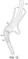
- FIG. 12illustrates delivery of the implant
- FIG. 13shows a fluoroscopic image of an implant in the position illustrated in FIG. 12 ;
- FIG. 14shows a fluoroscopic image of an implant in a lung as the delivery catheter is removed
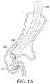
- FIG. 15illustrates the system after delivery of the implant.
- FIGS. 1 and 2illustrate the human respiratory system, including the trachea 12 , which directs air from the nose 8 or mouth 9 into the primary bronchus 16 .
- Airenters the lung 20 from the primary bronchus 16 .
- the primary bronchus 16branches into the secondary bronchus 22 , tertiary bronchus 24 , bronchioles 26 , terminal bronchioles 28 , and finally into the alveoli 30 .
- FIGS. 3-8illustrate various aspects of the guidewire.
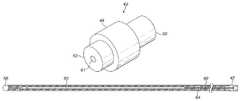
- FIG. 3shows a schematic view of an outer sheath of a guidewire, comprising a proximal section 40 , a transition section 42 , and a distal section 44 .
- the proximal section 40is formed of a spun coil which has a tight pitch and is substantially gapless.
- An example of such a coilis an HHS® (Helical Hollow Strand) Tube obtainable from Fort Wayne Metals of Fort Wayne, Ind., USA.
- a suitable tubecan be formed from a single layer of 304V Spring Temper stainless steel filament(s) of approximately 0.029 cm thickness to give a coil tube of approximately 0.17 cm OD.
- the proximal section 40can have a bore that is substantially unobstructed so as to give substantially consistent torque transmission and bending capability along its length.
- the distal section 44is formed from a wound coil, such as 304V Spring Temper stainless steel wire of approximately 0.025 cm thickness.
- a short section 46 near the distal end of the distal section 44is wound at a looser pitch so as to provide a highly flexible region as is shown in FIG. 4 .
- the proximal and distal sections 40 , 44are connected to each other by means of the transition section 42 .
- FIG. 5shows the transition section 42 in more detail.
- the transition section 42comprises a substantially cylindrical main body 48 having proximal and distal extensions 50 , 52 extending coaxially from opposite ends.
- the extensions 50 , 52are of reduced OD compared to the OD of the main body 48 and are sized to fit inside the respective bores of the proximal and distal sections 40 , 44 .
- the OD of the main body 48is substantially the same as that of the proximal and distal sections 40 , 44 .
- the transition sectioncan also be made from stainless steel and connected to the proximal and distal sections by welding. A deviation can be provided in the transition section 42 so that the outer coil tube is naturally in a slightly bent configuration.
- a hub 54is affixed at the proximal end of the proximal section 40 by which a user can apply torque to the guidewire.
- the hubcan be permanently affixed, such as by gluing, or can be removable.
- a ball 56can be welded to the distal end of the distal section 44 to provide an atraumatic surface.
- the proximal section 40can also include a marker section 58 to assist a user in determining the extend of insertion of the guidewire into a delivery system.
- a coreis provided inside the coil forming the distal section 44 , as shown in FIGS. 6 and 7 .
- the coreis formed of a wire 60 that is connected at one end in a bore 61 in the distal extension 52 of the transition section 42 , and at the other end is a bore in the ball 56 .
- the wire 60is substantially cylindrical at its ends, but has been flattened to a thickness of about half of the original wire diameter at a position 62 close to the proximal end so that it will preferably bend in a direction perpendicular to the plane of the flattened section and assist in steering the end in use.
- a series of markers 64are positioned along the core between the transition section 42 and the flattened section 62 .
- the markerscan be made of a material visible in a fluoroscopic imaging system, such as Pt/Ir.
- distal section 44is approximately half as long as the proximal section.
- the overall lengthcan be of the order of 120 cm, although other lengths and ratios can be used according to requirements.
- FIGS. 9-15illustrate systems and methods using the guidewire described above.
- the system of FIG. 9comprises a bronchoscope including a bronchoscope catheter 100 having a camera 102 at its distal end connected to a video processing system 104 .
- a delivery catheter 106extends through the lumen of the bronchoscope catheter 100 .
- the distal end 108 of the delivery catheter 106is provided with markers 110 visible to a fluoroscopic imaging system 112 .
- a guidewire 114 of the type described aboveextends through the lumen of the delivery catheter 106 and can be advanced out of the distal end 108 .
- the end of the guidewire 114also has markers 116 (corresponding to markers 64 described above).
- a dilator 118can be provided to endure a smooth transition between the outer surface of the guidewire 114 and the outer surface of the delivery catheters 106 .
- the system of FIG. 9is intended for use with an implant of the type shown in FIGS. 10 and 11 , although other shapes may also be used.
- the implantIn its normal state, the implant comprises an elongate member 120 that adopts a complex shape 122 comprising a series of curved sections, each curve centered on a separate axis.
- the implant 120can be made from Nitinol wire and can have atraumatic terminals at the ends and one or more length markers (not shown). For delivery, the implant 120 is distorted into a relatively straight configuration 124 and constrained in a delivery cartridge 126 .
- the bronchoscope catheter 100 of FIG. 9is advanced into the upper airways of a patient either to the extent of its available length, or until its physical size prevents further insertion without damage to the lung tissue.
- the delivery catheter 106together with the guidewire 114 , is advanced through the lumen of the bronchoscope catheter and into the airway.
- the guidewire 114is then further advanced along the delivery catheter 106 from the proximal end so as to extend from the distal end 108 and project further into the airway.
- the mark 58can be positioned so as to indicate when the distal end of the guidewire 114 is at the distal end of the catheter 108 .
- the guidewire 114As the guidewire 114 is advanced further, it can be steered by applying a torque to the hub 54 , the deviation allowing the distal end to be pointed in a required direction and the flexible section 46 and flattened core section 62 allowing the end to be eased into the required airway on contact with the wall of the airway. Progress can be monitored either via the viewing field of the bronchoscope, or by use of the remote fluoroscopic imaging system 112 once the end has passed out of this field of view.
- the deployment catheter 106can be advanced with the guidewire 114 until its distal end 118 is at or near the distal end of the guidewire 114 in the airway of interest.
- the proximal section 40is not configured to extend beyond the distal end 118 of the delivery catheter 106 . Consequently, the proximal section 40 can be configured for axial compression and torque transmission, together with the necessary degree of flexibility to be fed into the bronchoscope catheter 100 . In the example described above, this is achieved using the tight pitch spun coil structure for the proximal section 40 . By avoiding the need for the core 60 to extend to the hub 54 , the proximal section 40 can be more flexible than the previously proposed structure and so provides for easier insertion into the catheter 106 .
- the marker 58can be positioned so as to indicate that the distal end of the guidewire 114 is at or near the distal end 118 of the delivery catheter 106 , indicating to the user that further progress must be monitored using one or other of the imaging systems 104 , 112 .
- the distal endcan be directed off axis.
- This, together with the flexible region 46 and the flattened portion 62 of the core 60means that when the distal end reaches an airway junction 128 , torque can be applied at the hub 54 to cause the distal end to move radially in the airway, the flattened section 62 providing for preferential bending in the plane perpendicular to the plane of the flattened section 62 .
- the provision of the atraumatic ball 58 and flexible end 46mean that the airway tissue can provide a reaction surface to allow control of the position without damage to the tissue.
- FIG. 13shows remote imaging system view of the implant 120 at the end of the delivery catheter 106 .
- the implant 120is held in place by the pusher device 130 and the delivery catheter 106 is withdrawn, allowing the implant 120 to return to its as-manufactured shape ( FIG. 14 ), reducing the volume of lung tissue in that region as it does so.
- the connector 130is detached ( FIG. 15 ) and the bronchoscope and delivery catheters 100 , 106 can be withdrawn from the lung.
Landscapes
- Health & Medical Sciences (AREA)
- Life Sciences & Earth Sciences (AREA)
- Surgery (AREA)
- General Health & Medical Sciences (AREA)
- Engineering & Computer Science (AREA)
- Veterinary Medicine (AREA)
- Biomedical Technology (AREA)
- Heart & Thoracic Surgery (AREA)
- Public Health (AREA)
- Animal Behavior & Ethology (AREA)
- Nuclear Medicine, Radiotherapy & Molecular Imaging (AREA)
- Medical Informatics (AREA)
- Molecular Biology (AREA)
- Reproductive Health (AREA)
- Vascular Medicine (AREA)
- Hematology (AREA)
- Anesthesiology (AREA)
- Pulmonology (AREA)
- Biophysics (AREA)
- Pathology (AREA)
- Media Introduction/Drainage Providing Device (AREA)
- Surgical Instruments (AREA)
Abstract
Description
Claims (22)
Priority Applications (2)
| Application Number | Priority Date | Filing Date | Title |
|---|---|---|---|
| US15/719,792US10555736B2 (en) | 2016-09-30 | 2017-09-29 | Guidewire |
| US16/743,092US20200146688A1 (en) | 2016-09-30 | 2020-01-15 | Guidewire |
Applications Claiming Priority (2)
| Application Number | Priority Date | Filing Date | Title |
|---|---|---|---|
| US201662402852P | 2016-09-30 | 2016-09-30 | |
| US15/719,792US10555736B2 (en) | 2016-09-30 | 2017-09-29 | Guidewire |
Related Child Applications (1)
| Application Number | Title | Priority Date | Filing Date |
|---|---|---|---|
| US16/743,092ContinuationUS20200146688A1 (en) | 2016-09-30 | 2020-01-15 | Guidewire |
Publications (2)
| Publication Number | Publication Date |
|---|---|
| US20180092647A1 US20180092647A1 (en) | 2018-04-05 |
| US10555736B2true US10555736B2 (en) | 2020-02-11 |
Family
ID=60182823
Family Applications (2)
| Application Number | Title | Priority Date | Filing Date |
|---|---|---|---|
| US15/719,792Expired - Fee RelatedUS10555736B2 (en) | 2016-09-30 | 2017-09-29 | Guidewire |
| US16/743,092AbandonedUS20200146688A1 (en) | 2016-09-30 | 2020-01-15 | Guidewire |
Family Applications After (1)
| Application Number | Title | Priority Date | Filing Date |
|---|---|---|---|
| US16/743,092AbandonedUS20200146688A1 (en) | 2016-09-30 | 2020-01-15 | Guidewire |
Country Status (14)
| Country | Link |
|---|---|
| US (2) | US10555736B2 (en) |
| EP (1) | EP3519032A1 (en) |
| JP (1) | JP2019532720A (en) |
| KR (1) | KR20190059921A (en) |
| CN (1) | CN109789297A (en) |
| AR (1) | AR109753A1 (en) |
| BR (1) | BR112019006173A2 (en) |
| CA (1) | CA3038246A1 (en) |
| CL (1) | CL2019000816A1 (en) |
| CO (1) | CO2019003626A2 (en) |
| IL (1) | IL265474A (en) |
| MX (1) | MX2019003573A (en) |
| TW (1) | TW201813597A (en) |
| WO (1) | WO2018060848A1 (en) |
Cited By (1)
| Publication number | Priority date | Publication date | Assignee | Title |
|---|---|---|---|---|
| US20200114129A1 (en)* | 2018-02-26 | 2020-04-16 | Horizon Patents, LLC | Guidewire for catheter insertion |
Families Citing this family (2)
| Publication number | Priority date | Publication date | Assignee | Title |
|---|---|---|---|---|
| US20200254204A1 (en)* | 2019-01-15 | 2020-08-13 | Thomas Brian Moffat | Flexible articulating intubation tool |
| CN120570711A (en)* | 2025-08-04 | 2025-09-02 | 北京大学 | Instrument device |
Citations (55)
| Publication number | Priority date | Publication date | Assignee | Title |
|---|---|---|---|---|
| US4773432A (en) | 1987-02-09 | 1988-09-27 | Schneider-Shiley (Usa) Inc. | Bail-out catheter |
| US4917102A (en) | 1988-09-14 | 1990-04-17 | Advanced Cardiovascular Systems, Inc. | Guidewire assembly with steerable adjustable tip |
| US5054501A (en) | 1990-05-16 | 1991-10-08 | Brigham & Women's Hospital | Steerable guide wire for cannulation of tubular or vascular organs |
| US5333620A (en) | 1991-10-30 | 1994-08-02 | C. R. Bard, Inc. | High performance plastic coated medical guidewire |
| US5365943A (en)* | 1993-03-12 | 1994-11-22 | C. R. Bard, Inc. | Anatomically matched steerable PTCA guidewire |
| US5409015A (en)* | 1993-05-11 | 1995-04-25 | Target Therapeutics, Inc. | Deformable tip super elastic guidewire |
| US6174323B1 (en) | 1998-06-05 | 2001-01-16 | Broncus Technologies, Inc. | Method and assembly for lung volume reduction |
| US6183420B1 (en) | 1997-06-20 | 2001-02-06 | Medtronic Ave, Inc. | Variable stiffness angioplasty guide wire |
| US6287290B1 (en) | 1999-07-02 | 2001-09-11 | Pulmonx | Methods, systems, and kits for lung volume reduction |
| US6371928B1 (en) | 1997-11-07 | 2002-04-16 | Prolifix Medical, Inc. | Guidewire for positioning a catheter against a lumen wall |
| US6398775B1 (en) | 1999-10-21 | 2002-06-04 | Pulmonx | Apparatus and method for isolated lung access |
| US6409682B1 (en) | 1991-06-18 | 2002-06-25 | Scimed Life Systems, Inc. | Intravascular guide wire and method for manufacture thereof |
| US6459921B1 (en) | 1997-09-29 | 2002-10-01 | Scimed Life Systems, Inc. | Intravascular imaging guidewire |
| US6514290B1 (en) | 2000-03-31 | 2003-02-04 | Broncus Technologies, Inc. | Lung elastic recoil restoring or tissue compressing device and method |
| US6527761B1 (en) | 2000-10-27 | 2003-03-04 | Pulmonx, Inc. | Methods and devices for obstructing and aspirating lung tissue segments |
| US6599311B1 (en) | 1998-06-05 | 2003-07-29 | Broncus Technologies, Inc. | Method and assembly for lung volume reduction |
| US6669652B2 (en) | 2000-12-21 | 2003-12-30 | Advanced Cardiovascular Systems, Inc. | Guidewire with tapered distal coil |
| US6712812B2 (en) | 1999-08-05 | 2004-03-30 | Broncus Technologies, Inc. | Devices for creating collateral channels |
| US6716183B2 (en) | 1999-04-30 | 2004-04-06 | Applied Medical Resources Corporation | Guidewire |
| US6929637B2 (en) | 2002-02-21 | 2005-08-16 | Spiration, Inc. | Device and method for intra-bronchial provision of a therapeutic agent |
| US20050281798A1 (en) | 2004-06-16 | 2005-12-22 | Glen Gong | Targeting sites of damaged lung tissue using composition |
| US20050281796A1 (en) | 2004-06-16 | 2005-12-22 | Glen Gong | Targeting damaged lung tissue |
| US20050281799A1 (en) | 2004-06-16 | 2005-12-22 | Glen Gong | Targeting damaged lung tissue using compositions |
| US20050281739A1 (en) | 2004-06-16 | 2005-12-22 | Glen Gong | Imaging damaged lung tissue using compositions |
| US20050281740A1 (en) | 2004-06-16 | 2005-12-22 | Glen Gong | Imaging damaged lung tissue |
| US20050288684A1 (en) | 2004-06-16 | 2005-12-29 | Aronson Nathan A | Method of reducing collateral flow in a portion of a lung |
| US20060025815A1 (en) | 2004-07-08 | 2006-02-02 | Mcgurk Erin | Lung device with sealing features |
| US6997189B2 (en) | 1998-06-05 | 2006-02-14 | Broncus Technologies, Inc. | Method for lung volume reduction |
| US7115101B2 (en) | 1997-03-06 | 2006-10-03 | Scimed Life Systems, Inc. | Guide wire with hydrophilically coated tip |
| US7175644B2 (en) | 2001-02-14 | 2007-02-13 | Broncus Technologies, Inc. | Devices and methods for maintaining collateral channels in tissue |
| US20080021405A1 (en) | 2002-07-25 | 2008-01-24 | Precision Vascular Systems, Inc. | Medical device for navigation through anatomy and method of making same |
| US20080312543A1 (en) | 2007-06-18 | 2008-12-18 | Broncus Technologies, Inc. | Measurement of pulmonary hypertension from within the airways |
| WO2009020836A1 (en) | 2007-08-03 | 2009-02-12 | Boston Scientific Limited | Guidewires and methods for manufacturing guidewires |
| US20090131765A1 (en) | 2007-11-16 | 2009-05-21 | Broncus Technologies, Inc. | Method and system for measuring pulmonary artery circulation information |
| US7553810B2 (en) | 2004-06-16 | 2009-06-30 | Pneumrx, Inc. | Lung volume reduction using glue composition |
| US7595082B2 (en) | 2002-08-23 | 2009-09-29 | Cook Incorporated | Wire guide |
| US7608579B2 (en) | 2004-06-16 | 2009-10-27 | Pneumrx, Inc. | Lung volume reduction using glue compositions |
| US7662181B2 (en) | 2000-03-04 | 2010-02-16 | Pulmonx Corporation | Methods and devices for use in performing pulmonary procedures |
| US7670282B2 (en) | 2004-06-14 | 2010-03-02 | Pneumrx, Inc. | Lung access device |
| US7678767B2 (en) | 2004-06-16 | 2010-03-16 | Pneumrx, Inc. | Glue compositions for lung volume reduction |
| US7717115B2 (en) | 2002-11-27 | 2010-05-18 | Pulmonx Corporation | Delivery methods and devices for implantable bronchial isolation devices |
| US7766938B2 (en) | 2004-07-08 | 2010-08-03 | Pneumrx, Inc. | Pleural effusion treatment device, method and material |
| US20100297218A1 (en) | 2006-09-20 | 2010-11-25 | Pneumrx, Inc. | Tissue adhesive compositions and methods thereof |
| US7883474B1 (en) | 1993-05-11 | 2011-02-08 | Target Therapeutics, Inc. | Composite braided guidewire |
| US8142455B2 (en) | 2006-03-13 | 2012-03-27 | Pneumrx, Inc. | Delivery of minimally invasive lung volume reduction devices |
| US20120265100A1 (en) | 2011-04-18 | 2012-10-18 | Asahi Intecc Co., Ltd. | Medical guidewire |
| US20130096603A1 (en) | 2006-03-13 | 2013-04-18 | Pneumrx, Inc. | Lung Volume Reduction Devices, Methods, and Systems |
| US20130103059A1 (en) | 2008-09-12 | 2013-04-25 | Pneumrx, Inc. | Enhanced Efficacy Lung Volume Reduction Devices, Methods, and Systems |
| US8721734B2 (en) | 2009-05-18 | 2014-05-13 | Pneumrx, Inc. | Cross-sectional modification during deployment of an elongate lung volume reduction device |
| US8911465B2 (en) | 2006-08-16 | 2014-12-16 | Pneumrx, Inc. | Devices, systems, methods and kits for performing selective dissection of lung tissue |
| US20150119920A1 (en) | 2006-03-13 | 2015-04-30 | Pneumrx, Inc. | Genetically-Associated Chronic Obstructive Pulmonary Disease Treatment |
| US9125639B2 (en) | 2004-11-23 | 2015-09-08 | Pneumrx, Inc. | Steerable device for accessing a target site and methods |
| US9402633B2 (en) | 2006-03-13 | 2016-08-02 | Pneumrx, Inc. | Torque alleviating intra-airway lung volume reduction compressive implant structures |
| US20170156732A1 (en) | 2014-08-15 | 2017-06-08 | Pneumrx, Inc. | Coordinated delivery of copd treatment |
| US20180028193A1 (en) | 2013-10-25 | 2018-02-01 | Pneumrx, Inc. | Genetically-associated chronic obstructive pulmonary disease treatment |
Family Cites Families (7)
| Publication number | Priority date | Publication date | Assignee | Title |
|---|---|---|---|---|
| US5406960A (en)* | 1994-04-13 | 1995-04-18 | Cordis Corporation | Guidewire with integral core and marker bands |
| US5551444A (en)* | 1995-05-31 | 1996-09-03 | Radius Medical Technologies, Inc. | Flexible guidewire with radiopaque outer coil and non-radiopaque inner coil |
| JP5013547B2 (en)* | 2009-06-16 | 2012-08-29 | 朝日インテック株式会社 | Medical guidewire |
| JP2014100300A (en)* | 2012-11-20 | 2014-06-05 | Asahi Intecc Co Ltd | Guide wire |
| JP2016013269A (en)* | 2014-07-02 | 2016-01-28 | 朝日インテック株式会社 | Guide wire |
| US9993624B2 (en)* | 2014-08-08 | 2018-06-12 | DePuy Synthes Products, Inc. | Step feature for steerable guidewires |
| CN105749405A (en)* | 2014-12-19 | 2016-07-13 | 谷村哲明 | Catheter system comprising oviduct lens and combination method of system |
- 2017
- 2017-09-26WOPCT/IB2017/055847patent/WO2018060848A1/ennot_activeCeased
- 2017-09-26JPJP2019516975Apatent/JP2019532720A/enactivePending
- 2017-09-26KRKR1020197010070Apatent/KR20190059921A/ennot_activeWithdrawn
- 2017-09-26EPEP17790851.4Apatent/EP3519032A1/ennot_activeWithdrawn
- 2017-09-26CNCN201780059169.6Apatent/CN109789297A/enactivePending
- 2017-09-26CACA3038246Apatent/CA3038246A1/ennot_activeAbandoned
- 2017-09-26BRBR112019006173Apatent/BR112019006173A2/ennot_activeApplication Discontinuation
- 2017-09-26MXMX2019003573Apatent/MX2019003573A/enunknown
- 2017-09-27TWTW106133199Apatent/TW201813597A/enunknown
- 2017-09-29USUS15/719,792patent/US10555736B2/ennot_activeExpired - Fee Related
- 2017-09-29ARARP170102705Apatent/AR109753A1/enunknown
- 2019
- 2019-03-19ILIL265474Apatent/IL265474A/enunknown
- 2019-03-28CLCL2019000816Apatent/CL2019000816A1/enunknown
- 2019-04-11COCONC2019/0003626Apatent/CO2019003626A2/enunknown
- 2020
- 2020-01-15USUS16/743,092patent/US20200146688A1/ennot_activeAbandoned
Patent Citations (93)
| Publication number | Priority date | Publication date | Assignee | Title |
|---|---|---|---|---|
| US4773432A (en) | 1987-02-09 | 1988-09-27 | Schneider-Shiley (Usa) Inc. | Bail-out catheter |
| US4917102A (en) | 1988-09-14 | 1990-04-17 | Advanced Cardiovascular Systems, Inc. | Guidewire assembly with steerable adjustable tip |
| US5054501A (en) | 1990-05-16 | 1991-10-08 | Brigham & Women's Hospital | Steerable guide wire for cannulation of tubular or vascular organs |
| US6409682B1 (en) | 1991-06-18 | 2002-06-25 | Scimed Life Systems, Inc. | Intravascular guide wire and method for manufacture thereof |
| US5333620A (en) | 1991-10-30 | 1994-08-02 | C. R. Bard, Inc. | High performance plastic coated medical guidewire |
| US5365943A (en)* | 1993-03-12 | 1994-11-22 | C. R. Bard, Inc. | Anatomically matched steerable PTCA guidewire |
| US5409015A (en)* | 1993-05-11 | 1995-04-25 | Target Therapeutics, Inc. | Deformable tip super elastic guidewire |
| US7883474B1 (en) | 1993-05-11 | 2011-02-08 | Target Therapeutics, Inc. | Composite braided guidewire |
| US7115101B2 (en) | 1997-03-06 | 2006-10-03 | Scimed Life Systems, Inc. | Guide wire with hydrophilically coated tip |
| US6183420B1 (en) | 1997-06-20 | 2001-02-06 | Medtronic Ave, Inc. | Variable stiffness angioplasty guide wire |
| US6459921B1 (en) | 1997-09-29 | 2002-10-01 | Scimed Life Systems, Inc. | Intravascular imaging guidewire |
| US6371928B1 (en) | 1997-11-07 | 2002-04-16 | Prolifix Medical, Inc. | Guidewire for positioning a catheter against a lumen wall |
| US6599311B1 (en) | 1998-06-05 | 2003-07-29 | Broncus Technologies, Inc. | Method and assembly for lung volume reduction |
| US6997189B2 (en) | 1998-06-05 | 2006-02-14 | Broncus Technologies, Inc. | Method for lung volume reduction |
| US6174323B1 (en) | 1998-06-05 | 2001-01-16 | Broncus Technologies, Inc. | Method and assembly for lung volume reduction |
| US6716183B2 (en) | 1999-04-30 | 2004-04-06 | Applied Medical Resources Corporation | Guidewire |
| US7141046B2 (en) | 1999-07-02 | 2006-11-28 | Pulmonx | Methods, systems, and kits for lung volume reduction |
| US6287290B1 (en) | 1999-07-02 | 2001-09-11 | Pulmonx | Methods, systems, and kits for lung volume reduction |
| US7458963B2 (en) | 1999-07-02 | 2008-12-02 | Pulmonx | Methods, systems, and kits for lung volume reduction |
| US6709401B2 (en) | 1999-07-02 | 2004-03-23 | Pulmonx | Methods, systems, and kits for lung volume reduction |
| US7186259B2 (en) | 1999-07-02 | 2007-03-06 | Pulmonx | Methods, systems, and kits for lung volume reduction |
| US6878141B1 (en) | 1999-07-02 | 2005-04-12 | Pulmonx | Methods systems and kits for lung volume reduction |
| US6712812B2 (en) | 1999-08-05 | 2004-03-30 | Broncus Technologies, Inc. | Devices for creating collateral channels |
| US6398775B1 (en) | 1999-10-21 | 2002-06-04 | Pulmonx | Apparatus and method for isolated lung access |
| US7662181B2 (en) | 2000-03-04 | 2010-02-16 | Pulmonx Corporation | Methods and devices for use in performing pulmonary procedures |
| US6514290B1 (en) | 2000-03-31 | 2003-02-04 | Broncus Technologies, Inc. | Lung elastic recoil restoring or tissue compressing device and method |
| US6527761B1 (en) | 2000-10-27 | 2003-03-04 | Pulmonx, Inc. | Methods and devices for obstructing and aspirating lung tissue segments |
| US6997918B2 (en) | 2000-10-27 | 2006-02-14 | Pulmonx | Methods and devices for obstructing and aspirating lung tissue segments |
| US6669652B2 (en) | 2000-12-21 | 2003-12-30 | Advanced Cardiovascular Systems, Inc. | Guidewire with tapered distal coil |
| US7175644B2 (en) | 2001-02-14 | 2007-02-13 | Broncus Technologies, Inc. | Devices and methods for maintaining collateral channels in tissue |
| US6929637B2 (en) | 2002-02-21 | 2005-08-16 | Spiration, Inc. | Device and method for intra-bronchial provision of a therapeutic agent |
| US7942931B2 (en) | 2002-02-21 | 2011-05-17 | Spiration, Inc. | Device and method for intra-bronchial provision of a therapeutic agent |
| US20080021405A1 (en) | 2002-07-25 | 2008-01-24 | Precision Vascular Systems, Inc. | Medical device for navigation through anatomy and method of making same |
| US7595082B2 (en) | 2002-08-23 | 2009-09-29 | Cook Incorporated | Wire guide |
| US7717115B2 (en) | 2002-11-27 | 2010-05-18 | Pulmonx Corporation | Delivery methods and devices for implantable bronchial isolation devices |
| US7670282B2 (en) | 2004-06-14 | 2010-03-02 | Pneumrx, Inc. | Lung access device |
| US7775968B2 (en) | 2004-06-14 | 2010-08-17 | Pneumrx, Inc. | Guided access to lung tissues |
| US7553810B2 (en) | 2004-06-16 | 2009-06-30 | Pneumrx, Inc. | Lung volume reduction using glue composition |
| US20050281799A1 (en) | 2004-06-16 | 2005-12-22 | Glen Gong | Targeting damaged lung tissue using compositions |
| US20060004400A1 (en) | 2004-06-16 | 2006-01-05 | Mcgurk Erin | Method of treating a lung |
| USRE46209E1 (en) | 2004-06-16 | 2016-11-22 | Pneumrx, Inc. | Glue composition for lung volume reduction |
| US7468350B2 (en) | 2004-06-16 | 2008-12-23 | Pneumrx, Inc. | Glue composition for lung volume reduction |
| US8431537B2 (en) | 2004-06-16 | 2013-04-30 | Pneumrx, Inc. | Glue composition for lung volume reduction |
| US20050281798A1 (en) | 2004-06-16 | 2005-12-22 | Glen Gong | Targeting sites of damaged lung tissue using composition |
| US7549984B2 (en) | 2004-06-16 | 2009-06-23 | Pneumrx, Inc. | Method of compressing a portion of a lung |
| US20050288702A1 (en) | 2004-06-16 | 2005-12-29 | Mcgurk Erin | Intra-bronchial lung volume reduction system |
| US20050288684A1 (en) | 2004-06-16 | 2005-12-29 | Aronson Nathan A | Method of reducing collateral flow in a portion of a lung |
| US7608579B2 (en) | 2004-06-16 | 2009-10-27 | Pneumrx, Inc. | Lung volume reduction using glue compositions |
| US20050281800A1 (en) | 2004-06-16 | 2005-12-22 | Glen Gong | Targeting sites of damaged lung tissue |
| US20050281740A1 (en) | 2004-06-16 | 2005-12-22 | Glen Gong | Imaging damaged lung tissue |
| US7678767B2 (en) | 2004-06-16 | 2010-03-16 | Pneumrx, Inc. | Glue compositions for lung volume reduction |
| US20050281739A1 (en) | 2004-06-16 | 2005-12-22 | Glen Gong | Imaging damaged lung tissue using compositions |
| US7932225B2 (en) | 2004-06-16 | 2011-04-26 | Pneumrx, Inc. | Glue composition for lung volume reduction |
| US20050281796A1 (en) | 2004-06-16 | 2005-12-22 | Glen Gong | Targeting damaged lung tissue |
| US20140073588A1 (en) | 2004-06-16 | 2014-03-13 | Pneumrx, Inc. | Glue composition for lung volume reduction |
| US20060025815A1 (en) | 2004-07-08 | 2006-02-02 | Mcgurk Erin | Lung device with sealing features |
| US7766938B2 (en) | 2004-07-08 | 2010-08-03 | Pneumrx, Inc. | Pleural effusion treatment device, method and material |
| US9125639B2 (en) | 2004-11-23 | 2015-09-08 | Pneumrx, Inc. | Steerable device for accessing a target site and methods |
| US20150328435A1 (en) | 2004-11-23 | 2015-11-19 | Pneumrx, Inc. | Steerable device for accessing a target site and methods |
| US20130096603A1 (en) | 2006-03-13 | 2013-04-18 | Pneumrx, Inc. | Lung Volume Reduction Devices, Methods, and Systems |
| US20150080934A1 (en) | 2006-03-13 | 2015-03-19 | Pneumrx, Inc. | Minimally Invasive Lung Volume Reduction Devices, Methods, and Systems |
| US8282660B2 (en) | 2006-03-13 | 2012-10-09 | Pneumrx, Inc. | Minimally invasive lung volume reduction devices, methods, and systems |
| US20170065282A1 (en) | 2006-03-13 | 2017-03-09 | Pneumrx, Inc. | Cross-Sectional Modification During Deployment of an Elongate Lung Volume Reduction Device |
| US8157823B2 (en) | 2006-03-13 | 2012-04-17 | Pneumrx, Inc. | Lung volume reduction devices, methods, and systems |
| US20170027584A1 (en) | 2006-03-13 | 2017-02-02 | Pneumrx, Inc. | Torque Alleviating Intra-Airway Lung Volume Reduction Compressive Implant Structures |
| US8142455B2 (en) | 2006-03-13 | 2012-03-27 | Pneumrx, Inc. | Delivery of minimally invasive lung volume reduction devices |
| US20170027585A1 (en) | 2006-03-13 | 2017-02-02 | Pneumrx, Inc. | Lung Volume Reduction Devices, Methods, and Systems |
| US9402633B2 (en) | 2006-03-13 | 2016-08-02 | Pneumrx, Inc. | Torque alleviating intra-airway lung volume reduction compressive implant structures |
| US8668707B2 (en) | 2006-03-13 | 2014-03-11 | Pneumrx, Inc. | Minimally invasive lung volume reduction devices, methods, and systems |
| US9402632B2 (en) | 2006-03-13 | 2016-08-02 | Pneumrx, Inc. | Lung volume reduction devices, methods, and systems |
| US20150119920A1 (en) | 2006-03-13 | 2015-04-30 | Pneumrx, Inc. | Genetically-Associated Chronic Obstructive Pulmonary Disease Treatment |
| US8888800B2 (en) | 2006-03-13 | 2014-11-18 | Pneumrx, Inc. | Lung volume reduction devices, methods, and systems |
| US8157837B2 (en) | 2006-03-13 | 2012-04-17 | Pneumrx, Inc. | Minimally invasive lung volume reduction device and method |
| US20140371705A1 (en) | 2006-03-13 | 2014-12-18 | Pneumrx, Inc. | Minimally Invasive Lung Volume Reduction Devices, Methods, and Systems |
| US8932310B2 (en) | 2006-03-13 | 2015-01-13 | Pneumrx, Inc. | Minimally invasive lung volume reduction devices, methods, and systems |
| US20150073563A1 (en) | 2006-03-13 | 2015-03-12 | Pneumrx, Inc. | Cross-Sectional Modification During Deployment of an Elongate Lung Volume Reduction Device |
| US20150142035A1 (en) | 2006-08-16 | 2015-05-21 | Pneumrx, Inc. | Devices, Systems, Methods and Kits for Performing Selective Dissection of Lung Tissue |
| US8911465B2 (en) | 2006-08-16 | 2014-12-16 | Pneumrx, Inc. | Devices, systems, methods and kits for performing selective dissection of lung tissue |
| US20100297218A1 (en) | 2006-09-20 | 2010-11-25 | Pneumrx, Inc. | Tissue adhesive compositions and methods thereof |
| US20080312543A1 (en) | 2007-06-18 | 2008-12-18 | Broncus Technologies, Inc. | Measurement of pulmonary hypertension from within the airways |
| WO2009020836A1 (en) | 2007-08-03 | 2009-02-12 | Boston Scientific Limited | Guidewires and methods for manufacturing guidewires |
| US20180064411A1 (en) | 2007-11-16 | 2018-03-08 | Pneumrx, Inc. | Method and system for measuring pulmonary artery circulation information |
| US20090131765A1 (en) | 2007-11-16 | 2009-05-21 | Broncus Technologies, Inc. | Method and system for measuring pulmonary artery circulation information |
| US20130184579A1 (en) | 2007-11-16 | 2013-07-18 | Pneumrx, Inc. | Method and System for Measuring Pulmonary Artery Circulation Information |
| US9173669B2 (en) | 2008-09-12 | 2015-11-03 | Pneumrx, Inc. | Enhanced efficacy lung volume reduction devices, methods, and systems |
| US8632605B2 (en) | 2008-09-12 | 2014-01-21 | Pneumrx, Inc. | Elongated lung volume reduction devices, methods, and systems |
| US20160113657A1 (en) | 2008-09-12 | 2016-04-28 | Pneumrx, Inc. | Enhanced Efficacy Lung Volume Reduction Devices, Methods, and Systems |
| US9192403B2 (en) | 2008-09-12 | 2015-11-24 | Pneumrx, Inc. | Elongated lung volume reduction devices, methods, and systems |
| US20130103059A1 (en) | 2008-09-12 | 2013-04-25 | Pneumrx, Inc. | Enhanced Efficacy Lung Volume Reduction Devices, Methods, and Systems |
| US8721734B2 (en) | 2009-05-18 | 2014-05-13 | Pneumrx, Inc. | Cross-sectional modification during deployment of an elongate lung volume reduction device |
| US20120265100A1 (en) | 2011-04-18 | 2012-10-18 | Asahi Intecc Co., Ltd. | Medical guidewire |
| US20180028193A1 (en) | 2013-10-25 | 2018-02-01 | Pneumrx, Inc. | Genetically-associated chronic obstructive pulmonary disease treatment |
| US20170156732A1 (en) | 2014-08-15 | 2017-06-08 | Pneumrx, Inc. | Coordinated delivery of copd treatment |
Non-Patent Citations (8)
| Title |
|---|
| PneumRx Lung Volume Reduction Devices (LVRD) Instructions for Use, 2007, 8 pages. |
| PneumRx RePneu Coil System Instructions for Use, Dec. 2014, pp. 1-8. |
| PneumRx RePneu Lung Volume Reduction Coil (LVRC) Instructions for Use, 2010, pp. 1-8. |
| PneumRx RePneu Lung Volume Reduction Coil (LVRC) System Instructions for Use, Jun. 2015, pp. 1-8. |
| PneumRx, Inc., 3 Marker Guidewire Assembly schematics, drawn by D. Lehrberg, 2011, 1 page. |
| PneumRx, Inc., Guidewire Core Wire and Guidewire Coil schematics, drawn by D. Lehrberg, 2010, 2 pages. |
| PneumRx, Inc., Introducer RO Coil schematics, drawn by P. Wu, 2007, 1 page. |
| PneumRx, Inc., RePneu Lung Volume Reduction Coil (LVRC) System Instructions for Use, Feb. 2014, pp. 1-8. |
Cited By (1)
| Publication number | Priority date | Publication date | Assignee | Title |
|---|---|---|---|---|
| US20200114129A1 (en)* | 2018-02-26 | 2020-04-16 | Horizon Patents, LLC | Guidewire for catheter insertion |
Also Published As
| Publication number | Publication date |
|---|---|
| US20200146688A1 (en) | 2020-05-14 |
| CL2019000816A1 (en) | 2019-06-21 |
| TW201813597A (en) | 2018-04-16 |
| CN109789297A (en) | 2019-05-21 |
| BR112019006173A2 (en) | 2019-06-18 |
| EP3519032A1 (en) | 2019-08-07 |
| AR109753A1 (en) | 2019-01-23 |
| US20180092647A1 (en) | 2018-04-05 |
| JP2019532720A (en) | 2019-11-14 |
| CO2019003626A2 (en) | 2019-06-28 |
| CA3038246A1 (en) | 2018-04-05 |
| IL265474A (en) | 2019-05-30 |
| WO2018060848A1 (en) | 2018-04-05 |
| MX2019003573A (en) | 2019-06-03 |
| KR20190059921A (en) | 2019-05-31 |
Similar Documents
| Publication | Publication Date | Title |
|---|---|---|
| JP5023067B2 (en) | Connecting wire guide | |
| US8043232B2 (en) | High performance wire guide | |
| US20200146688A1 (en) | Guidewire | |
| US5282478A (en) | Guidewire extension system with coil connectors | |
| AU723302B2 (en) | Torquable, low mass medical guidewire | |
| US20190201017A1 (en) | Deflectable guide catheters and related methods | |
| CN105455930B (en) | Lung volume reduction elasticity implant and instrument | |
| ES3025735T3 (en) | Lung volume reduction elastic implant and lung volume reduction device | |
| US20110270169A1 (en) | Steerable Stylet with Guidewire Tip | |
| US20140018626A1 (en) | Telescopic intubation tube | |
| US20080269721A1 (en) | Interventional medical device system having a spiral section and radiopaque marker and method of making the same | |
| EP3363408B1 (en) | Lung-volume-reduction elastic implant and lung-volume-reduction instrument | |
| CN110475578A (en) | For conveying the flexible torque cable of medical device | |
| CN108495683A (en) | Anchor seal wire | |
| CN118476900A (en) | Implant, delivery mechanism, lung volume reduction implant device and system | |
| CN108210133B (en) | implant | |
| WO2018121346A1 (en) | Lung volume reduction elastic implant and lung volume reduction instrument | |
| WO2019140179A1 (en) | Methods and devices for the treatment of pulmonary disorders |
Legal Events
| Date | Code | Title | Description |
|---|---|---|---|
| FEPP | Fee payment procedure | Free format text:ENTITY STATUS SET TO UNDISCOUNTED (ORIGINAL EVENT CODE: BIG.); ENTITY STATUS OF PATENT OWNER: LARGE ENTITY | |
| AS | Assignment | Owner name:PNEUMRX, INC., CALIFORNIA Free format text:ASSIGNMENT OF ASSIGNORS INTEREST;ASSIGNORS:MACHOLD, TIMOTHY;MATHIS, MARK;RODRIGUEZ, VERNA;AND OTHERS;SIGNING DATES FROM 20171012 TO 20171115;REEL/FRAME:044411/0866 | |
| STPP | Information on status: patent application and granting procedure in general | Free format text:DOCKETED NEW CASE - READY FOR EXAMINATION | |
| STPP | Information on status: patent application and granting procedure in general | Free format text:NOTICE OF ALLOWANCE MAILED -- APPLICATION RECEIVED IN OFFICE OF PUBLICATIONS | |
| STPP | Information on status: patent application and granting procedure in general | Free format text:PUBLICATIONS -- ISSUE FEE PAYMENT RECEIVED | |
| STCF | Information on status: patent grant | Free format text:PATENTED CASE | |
| AS | Assignment | Owner name:EKOS LLC, WASHINGTON Free format text:NUNC PRO TUNC ASSIGNMENT;ASSIGNOR:PNEUMRX LLC;REEL/FRAME:051925/0675 Effective date:20191209 Owner name:PNEUMRX LLC, DELAWARE Free format text:CHANGE OF NAME;ASSIGNOR:PNEUMRX, INC.;REEL/FRAME:051925/0350 Effective date:20191203 | |
| FEPP | Fee payment procedure | Free format text:MAINTENANCE FEE REMINDER MAILED (ORIGINAL EVENT CODE: REM.); ENTITY STATUS OF PATENT OWNER: LARGE ENTITY | |
| LAPS | Lapse for failure to pay maintenance fees | Free format text:PATENT EXPIRED FOR FAILURE TO PAY MAINTENANCE FEES (ORIGINAL EVENT CODE: EXP.); ENTITY STATUS OF PATENT OWNER: LARGE ENTITY | |
| STCH | Information on status: patent discontinuation | Free format text:PATENT EXPIRED DUE TO NONPAYMENT OF MAINTENANCE FEES UNDER 37 CFR 1.362 | |
| FP | Lapsed due to failure to pay maintenance fee | Effective date:20240211 |