US10555727B2 - Vascular closure device with removable guide member - Google Patents
Vascular closure device with removable guide memberDownload PDFInfo
- Publication number
- US10555727B2 US10555727B2US15/192,632US201615192632AUS10555727B2US 10555727 B2US10555727 B2US 10555727B2US 201615192632 AUS201615192632 AUS 201615192632AUS 10555727 B2US10555727 B2US 10555727B2
- Authority
- US
- United States
- Prior art keywords
- guide member
- vascular closure
- toggle
- closure device
- sealing device
- Prior art date
- Legal status (The legal status is an assumption and is not a legal conclusion. Google has not performed a legal analysis and makes no representation as to the accuracy of the status listed.)
- Active, expires
Links
Images


Classifications
- A—HUMAN NECESSITIES
- A61—MEDICAL OR VETERINARY SCIENCE; HYGIENE
- A61B—DIAGNOSIS; SURGERY; IDENTIFICATION
- A61B17/00—Surgical instruments, devices or methods
- A61B17/0057—Implements for plugging an opening in the wall of a hollow or tubular organ, e.g. for sealing a vessel puncture or closing a cardiac septal defect
- A61B2017/00575—Implements for plugging an opening in the wall of a hollow or tubular organ, e.g. for sealing a vessel puncture or closing a cardiac septal defect for closure at remote site, e.g. closing atrial septum defects
- A61B2017/00601—Implements entirely comprised between the two sides of the opening
- A—HUMAN NECESSITIES
- A61—MEDICAL OR VETERINARY SCIENCE; HYGIENE
- A61B—DIAGNOSIS; SURGERY; IDENTIFICATION
- A61B17/00—Surgical instruments, devices or methods
- A61B17/0057—Implements for plugging an opening in the wall of a hollow or tubular organ, e.g. for sealing a vessel puncture or closing a cardiac septal defect
- A61B2017/00575—Implements for plugging an opening in the wall of a hollow or tubular organ, e.g. for sealing a vessel puncture or closing a cardiac septal defect for closure at remote site, e.g. closing atrial septum defects
- A61B2017/0061—Implements located only on one side of the opening
- A—HUMAN NECESSITIES
- A61—MEDICAL OR VETERINARY SCIENCE; HYGIENE
- A61B—DIAGNOSIS; SURGERY; IDENTIFICATION
- A61B17/00—Surgical instruments, devices or methods
- A61B17/0057—Implements for plugging an opening in the wall of a hollow or tubular organ, e.g. for sealing a vessel puncture or closing a cardiac septal defect
- A61B2017/00575—Implements for plugging an opening in the wall of a hollow or tubular organ, e.g. for sealing a vessel puncture or closing a cardiac septal defect for closure at remote site, e.g. closing atrial septum defects
- A61B2017/00623—Introducing or retrieving devices therefor
- A—HUMAN NECESSITIES
- A61—MEDICAL OR VETERINARY SCIENCE; HYGIENE
- A61B—DIAGNOSIS; SURGERY; IDENTIFICATION
- A61B17/00—Surgical instruments, devices or methods
- A61B2017/00831—Material properties
- A61B2017/00902—Material properties transparent or translucent
- A61B2017/00907—Material properties transparent or translucent for light
- A—HUMAN NECESSITIES
- A61—MEDICAL OR VETERINARY SCIENCE; HYGIENE
- A61B—DIAGNOSIS; SURGERY; IDENTIFICATION
- A61B17/00—Surgical instruments, devices or methods
- A61B17/22—Implements for squeezing-off ulcers or the like on inner organs of the body; Implements for scraping-out cavities of body organs, e.g. bones; for invasive removal or destruction of calculus using mechanical vibrations; for removing obstructions in blood vessels, not otherwise provided for
- A61B2017/22038—Implements for squeezing-off ulcers or the like on inner organs of the body; Implements for scraping-out cavities of body organs, e.g. bones; for invasive removal or destruction of calculus using mechanical vibrations; for removing obstructions in blood vessels, not otherwise provided for with a guide wire
- A—HUMAN NECESSITIES
- A61—MEDICAL OR VETERINARY SCIENCE; HYGIENE
- A61B—DIAGNOSIS; SURGERY; IDENTIFICATION
- A61B17/00—Surgical instruments, devices or methods
- A61B17/28—Surgical forceps
- A61B17/29—Forceps for use in minimally invasive surgery
- A61B17/2909—Handles
- A61B2017/2912—Handles transmission of forces to actuating rod or piston
- A61B2017/2923—Toothed members, e.g. rack and pinion
Definitions
- the present disclosurerelates to a vascular closure device with a removable guide member for a guide wire.
- Percutaneous access of the vascular system for vascular device deliveryis a common medical procedure. Typically this involves using a hollow needle to puncture a vessel, then introducing an introducer sheath to open the puncture site for the introduction of catheters and wire guides for navigation through the vascular system to facilitate delivery. For example, in many cases, vascular access requires introduction of catheters and guide wires through the femoral artery. Once the procedure is completed, the devices are removed from the patient and pressure is applied to the puncture site to stop the bleeding. Thereafter, the puncture may be sealed using a closure device.
- Closure devicesgenerally consist of three basic sealing components: a toggle (or anchor) member, a sealing member (or plug), and a filament (or suture). To lock the components together within the puncture, a locking member may be used.
- An embodiment of the present disclosureis a vascular closure configured to be disposed along a guide wire toward a puncture of a vessel.
- the vascular closure deviceincludes a sealing device configured to seal the puncture of the vessel, and a delivery assembly that releasably holds the sealing device.
- the vascular closure deviceincludes a moveable guide member that is elongate along a longitudinal axis and that extends through at least a portion of the sealing device.
- the movable guide memberincludes a lumen that extends along the longitudinal axis and that is sized and configured to receive the guide wire as the vascular closure device is positioned along the guide wire.
- the guide memberis moveable relative to the delivery assembly so as to be removed from the at least a portion of the sealing device.
- vascular closureconfigured to be disposed along a guide wire toward a puncture of a vessel.
- the vascular closure deviceincludes a sealing device configured to seal the puncture of the vessel.
- the vascular closure devicealso includes a delivery assembly including a front end and a rear end spaced from the front end in a proximal direction, and the front end of the delivery assembly releasably holds the sealing device.
- a moveable guide memberis supported by the delivery assembly and extends through at least a portion of the sealing device.
- the movable guide memberincludes a distal end, a proximal end spaced from the distal end in the proximal direction, and a lumen that extends from the distal end toward the proximal end in the proximal direction.
- the lumenis sized and configured to receive the guide wire through the distal end when the vascular closure device is disposed along the guide wire.
- the movable guide memberis configured to translate relative to the delivery assembly from a first position where the movable guide member extends through the at least a portion of the sealing device, to a second position where the movable guide member does not extend through the at least a portion of the sealing device.
- Another embodiment of present disclosureis a method for sealing a puncture of a vessel.
- the methodcomprising the step of positioning a guide member that extends through at least a portion of a sealing device along a guide wire such that a proximal end of a guide wire enters a lumen of the guide member.
- a delivery assemblysupports the guide member and releasably holds the sealing device.
- the methodincludes the step of advancing the guide member and the sealing device along the guide wire in a distal direction.
- the methodalso includes moving the guide member relative to the delivery assembly along a proximal direction that is opposite to the distal direction so to as remove the guide member from the at least a portion of the sealing device.
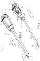
- FIG. 1is a perspective view of a vascular closure device of a puncture closure system in accordance with an embodiment of the present disclosure
- FIG. 2is a perspective view of the vascular closure device shown in FIG. 1 , including a sealing device;
- FIG. 3is a partial cut-away view of the vascular closure device shown in FIG. 2 ;
- FIG. 4is a perspective view of the sealing device in the vascular closure device illustrated in FIGS. 2 and 3 ;
- FIG. 5is a detailed sectional view of a distal portion of the vascular closure device shown in FIGS. 1-4 ;
- FIGS. 6A-6Care rear perspective views of the vascular closure device with portions of the device removed for clarity;
- FIG. 6Dis a cross-sectional view of the vascular closure device shown in FIG. 6A , taken along line 6 D- 6 D;
- FIG. 6Eis a perspective view of the a release component, delivery component and a tensioning element of the vascular closure device shown in FIGS. 1-4 ;
- FIG. 6Fis a perspective cross-sectional view of the release component, delivery component, and the tensioning element shown in FIG. 6E , taken along line 6 F- 6 F;
- FIG. 6Gis a perspective view of the delivery component and tensioning element of the vascular closure device shown in FIG. 6E ;
- FIGS. 6H and 6Iare perspective and top views of the release component and tensioning element of the vascular closure device shown in FIGS. 1-4 ;
- FIGS. 7A and 7Bare side sectional views illustrating operation of the tensioning element illustrated in FIG. 6D ;
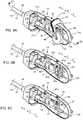
- FIG. 8Ais a sectional view of a guide member illustrated in FIG. 1 ;
- FIG. 8Bis a sectional view of a guide member including a gripping member, according to another embodiment of the present disclosure.
- FIG. 9Ais a sectional view of a proximal end of the guide member shown in FIG. 8A ;
- FIG. 9Bis a sectional view of a proximal end of the guide member according another embodiment of the present disclosure.
- FIG. 9Cis a sectional view of a proximal end of the guide member according another embodiment of the present disclosure.
- FIG. 9Dis a sectional view of a proximal end of the guide member according another embodiment of the present disclosure.
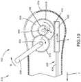
- FIG. 10is sectional view of illustrating an actuator configured to move the guide member relative to the sealing device, according to an embodiment of the present disclosure
- FIG. 11Ais a schematic showing an access sheath partially disposed within a vessel through a puncture site in the vessel;
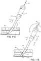
- FIG. 11Bis a schematic showing the closure device of FIG. 1 translated into an access channel of the access sheath such that a distal end of the toggle is positioned distal to a distal end of the access sheath;
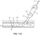
- FIG. 11Cis a schematic showing the guide member 135 removed from the closure device
- FIG. 11Dis a schematic showing the access sheath and closure device combination pulled in a proximal direction such that the toggle is proximate to the puncture site;
- FIG. 11Eis a schematic showing actuation of the actuator to release the toggle and apply a tension to a filament
- FIG. 11Fis a schematic showing the deployment device being pulled in a proximal direction such that the toggle abuts the vessel wall;
- FIG. 11Gis a schematic showing deployment of a plug of the closure device
- FIG. 11His a schematic showing deployment of the a locking member against the plug
- FIG. 11Iis a schematic showing the locking member being tamped against the plug with a tamper
- FIG. 11Jis a schematic showing the deployment of the sealing device fully sealing the puncture site.
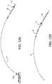
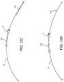
- FIG. 12A-12Dare schematic views illustrating removal of the guide member from the closure device.
- embodiments of the present disclosureinclude a puncture closure system 10 used to seal puncture in an arterial wall.
- the puncture closure system 10includes an introducer (not shown), such as a dilator, and a vascular closure device 12 that is configured to seal the puncture in an arterial wall.
- the vascular closure device 12includes an access sheath 23 , a sealing device 18 , and a delivery assembly 14 that releasably carries the sealing device 18 and that is insertable into the access sheath 23 .
- the access sheath 23can be inserted into the puncture along a guide wire 15 ( FIG. 11A ) and over the introducer (not shown) to form an insertion assembly.
- the delivery assembly 14can be inserted over the guide wire 15 into the access sheath 23 and coupled with the access sheath 23 to position the sealing device 18 ( FIG. 11B ) in the artery.
- the vascular closure device 12includes a removable guide member 135 carried by the delivery assembly 14 .
- the removable guide member 135receives the guide wire 15 as further explained below.
- the delivery assembly 14can be inserted into and coupled to the access sheath 23 .
- the access sheath 23is elongate along a longitudinal direction L.
- the access sheath 23defines a distal end D A , a proximal end P A , and an access channel 36 ( FIG. 11A ) that extends from the proximal end P A to the distal end D A along the longitudinal direction L.
- the access sheath 23also includes a hub 21 b and a shaft 21 d that extends from the hub 21 b .
- the proximal end, which can be referred to as the rearward end, of the access sheathincludes the hub 21 b that is configured to be coupled to a portion of the delivery assembly 14 .
- the hub 21 bincludes a first engagement member (not shown) and the delivery assembly 14 includes a second engagement member (not shown) that couples the first engagement member so that the access sheath 23 and delivery assembly 14 are fixed with to each other.
- the first and second engagement memberscan be snap-fit features or other types of mechanical interlocks.
- the vascular closure device 12includes a sealing device 18 for sealing a puncture.
- the sealing device 18which may be referred to as implantable unit, includes a toggle 40 , a suture 44 coupled to the toggle 40 , a plug 88 coupled to the suture 44 and spaced from the toggle 40 in a proximal direction 4 , and a locking member 42 disposed on the suture 44 proximal to the plug 88 .
- the vascular closure device 12is configured such that after a distal portion of delivery assembly 14 is inserted through the puncture site of the vessel, the sealing device 18 can be deployed to seal or otherwise close the puncture site.
- the delivery assembly 14controls orientation of the toggle 40 as the sealing device 18 is advanced through the access sheath 23 in an easier and more efficient manner. Furthermore, the delivery assembly 14 is also configured to reduce forces required to deploy the sealing device 18 and seal the puncture. In one example, deployment forces are reduced by providing a guide member 135 that 1) guides the delivery assembly 14 into position, and 2) can be removed from the sealing device 18 and/or completely from the delivery assembly 14 . Removal of the guide member 135 prior to deployment of the sealing device 18 creates additional space within the vascular closure device 12 , which in turn, helps reduces forces required to fully deploy the sealing device 18 .
- the toggle 40includes a distal end 41 d , a proximal end 41 p opposite to the proximal end 41 p , and a plurality of apertures (not numbered) extending therethrough.
- the suture 44is extends through the apertures as illustrated such that an end of the suture 44 is formed into a slidable knot 37 .
- the knot 37is slidable along the suture 44 between the plug 88 and the locking member 42 .
- the toggle 40is adjacent an inner surface of the vessel and the locking member 42 squeezes the toggle 40 the plug 88 against the vessel to seal the puncture.
- the sealing device 18is formed with materials suitable for surgical procedures.
- the toggle 40can be made of any biocompatible material.
- the toggle 40can be made of a polylactic-coglycolic acid or other synthetic absorbable polymer that degrades in the presence of water into naturally occurring metabolites.
- the toggle 40can be made of stainless steel, biocorrodible iron, and biocorrodible magnesium. It should be appreciated, however, that the toggle 40 can be made of other materials and can have other configurations so long as it can be seated inside the vessel against the vessel wall.
- the plug 88can comprise a strip of compressible, resorbable, collagen foam and can be made of a fibrous collagen mix of insoluble and soluble collagen that is cross linked for strength. It should be appreciated, however, that the plug member 88 can have any configuration as desired and can be made from any material as desired.
- the suture 44can be any elongate member, such as, for example a filament, thread, or braid.
- the delivery assembly 14includes a handle member 20 , a release component 22 , a delivery component 26 , a tensioning element 28 coupled to the delivery component 26 , one or more actuators 38 operatively to the release component 22 , a tamper 54 disposed along the suture 44 , and a guide member 135 .
- the toggle 40is trapped between the release component 22 and the delivery component 26 as shown in FIG. 5 .
- the release component 22is also operatively associated with the suture 44 such that actuation of the actuator 38 1) releases the toggle 40 , and 2) applies tension to the suture 44 .
- the tension applied the suture 44 by the actuator 38urges the toggle 40 against the delivery component 26 and orients the toggle 40 into the sealing position.
- the delivery assembly 14also carries the removable guide member 135 such that the guide member 135 extends through the sealing device 18 and is configured to receive a guide wire 15 .
- the guide member 135extends through the plug 88 and toggle 40 .
- the delivery assembly 14can be configured so that the guide member 135 (and guide wire 15 ) extends through the plug 88 but along the side of the toggle 40 .
- the guide member 135is configured to be removed from at least the sealing device 18 before the sealing device 18 is deployed to seal the puncture.
- the delivery assembly 14is elongate along a longitudinal direction L and includes a rear end 16 p and a front end 16 d spaced from the rear end 16 p along an axis 6 that is aligned with the longitudinal direction L.
- the delivery assembly 14defines a length D 1 that extend from the front end 16 d to the rear end 16 p along the longitudinal direction L.
- the longitudinal direction Lcan include and define a distal direction 2 that extends from the rear end 16 p toward the front end 16 d .
- the longitudinal direction Lcan include and define a proximal direction 4 that is opposite the distal direction 2 and that extends from front end 16 d toward the rear end 16 p .
- the delivery assembly 14is configured to insert the toggle 40 into the vessel along an insertion direction I through the access sheath 23 .
- the longitudinal direction Lcan be aligned with the insertion direction I during a portion of the sealing procedure.
- the delivery assembly 14includes a handle member 20 .
- the handle member 20includes a housing 21 a and a cavity 21 c defined at least partly by housing 21 a and a hub 21 b of the access sheath 23 .
- the cavity 21 cis sized to contain a portion of the release component 22 , the delivery component 26 , and the tensioning element 28 .
- the handle member 20supports the release component 22 such that release component 22 extends from handle member 20 in the distal direction 2 .
- the delivery component 26also supported by the handle member 20 and extends along the distal direction 2 within a lumen of the release component 22 .
- a portion of delivery component 26is shown in dashed lines in FIGS. 2 and 3 .
- the tensioning element 28is contained in the housing 21 a and is coupled to a proximal end of the release component 22 .
- the actuator 38is coupled to both the handle member 20 and the release component 22 .
- the release component 22is elongate along a first or longitudinal direction L defines a distal end 25 d and a proximal end 25 p spaced from the distal end 25 d along the longitudinal direction L.
- the release component 22includes a hub 24 and a release tube 46 that is fixed to the hub 24 and that extends from the hub 24 in the distal direction 2 .
- the hub 24is disposed at the proximal end 25 p of the release component 22 .
- the release hub 24includes a pair of tabs 29 a , 29 b , and a pulley 60 coupled to and disposed between the tabs 29 a , 29 b .
- the pulley 60defines a curved track that receives the suture 44 as will be explained below.
- the hub 24defines a slot 50 that is elongate along the longitudinal direction L and is aligned with the release tube 46 .
- the slot 50is sized to receiver a coupler 31 of the tensioning element 28 .
- the release tube 46includes a release tube body 51 that is elongate along the longitudinal direction L.
- the release tube body 51defines a release tube channel 52 ( FIG. 6D ) that extends from the hub 24 toward the distal end 25 d .
- the release tube channel 52extends completely through the release tube body 51 from the hub 24 to the distal end 25 d .
- the release tube body 51is cylindrical such that the release tube channel 52 is radially enclosed. It should be appreciated, however, that the release tube channel 52 can extend partially through the release tube body 51 as desired and that the release tube body 51 can have other configurations as desired.
- the release tube body 51can be U-shaped such that the release tube channel 52 is partially radially open.
- the release tube channel 52is sized to slidably receive a portion of the delivery component 26 such that the release component 22 is movable relative to the delivery component 26 .
- the suture 44extends around the pulley 60 along the guide track and into the tensioning element 28 .
- the tensioning element 28is positioned alongside the release component 22 . It should be appreciated, however, that in some embodiments, the tensioning element 28 is positioned proximal to the release tube and is in-line with the release component 22 such that the suture 44 extends through the release tube 46 and into the tensioning element 28 along the first direction L.
- the release component 22can be operatively coupled to the actuator 38 via one or more mating members.
- the release component 22includes at least one mating member 64 that mates with a corresponding mating member 68 of the actuator 38 .
- the mating member 64is shown as a pair of matting member 64 a , 64 b that are engaged with mating member 68 so as to transfer the motion of the actuator 38 to the release component 22 .
- the release component mating member 64is a pair of slots 64 a and 64 b defined by the respective pair of tabs 29 a and 29 b of the hub 24 .
- Each slot 64 a and 64 bis elongate along a vertical direction V that is perpendicular to the longitudinal direction L.
- the mating member 68which can be a pin, is disposed inside the slots 64 a and 64 b such that actuation of the actuator 38 causes the release component 22 to translate along the longitudinal direction L.
- the mating member 64can have any configuration as desired.
- the mating member 64can be a bore having a diameter that is equal to that of the pin such that translation of the actuator 38 causes the release component 22 to translate along the first direction L.
- FIGS. 6D-6Gillustrates a delivery component 26 designed to carry the sealing device 18 .
- the delivery component 26extends along the inside of the release component 22 toward the front end 16 d of the delivery assembly 14 .
- the delivery component 26includes a delivery tube body 80 that is elongate along the direction L.
- the delivery tube body 80defines a distal end 27 d , a proximal end 27 p spaced from the distal end 27 d in the direction L, and an inner surface 81 .
- the inner surface 8defines a delivery tube channel 84 that extends at least partially through the delivery tube body 80 along the direction L.
- the delivery tube channel 84extends completely through the delivery tube body 80 from the proximal end 27 p to the distal end 27 d .
- the channel 84can extend along a portion of the delivery tube body 80 .
- the delivery tube body 80is cylindrical such that the delivery tube channel 84 is radially enclosed. It should be appreciated, however, that the delivery tube channel 84 can extend partially through the delivery tube body 80 .
- the delivery tube body 80can have other configurations as desired.
- the delivery tube body 80can be U-shaped such that the delivery tube channel 84 is partially radially open.
- the distal end 27 d of delivery componentholds at least a portion of the sealing device 18 ( FIG. 5 ).
- the proximal end 27 p of delivery componentis fixed to the tensioning element 28 . Because the tensioning element 28 is fixed to the housing 21 a , the delivery component 26 is fixed to the housing 21 a and thus the handle member 20 .
- the delivery assembly 14releasably carries at least a portion of the sealing device 18 .
- the plug 88 and locking member 42are retained within the delivery tube channel 84 , while the toggle 40 is configured to be initially trapped between the delivery component 26 and the release component 22 .
- the tamper 54is also positioned in the channel 84 .
- the distal end 27 d of the delivery component 26defines an offset surface 49 , which can be angled with respect to the longitudinal axis 6 .
- the offset surface 49 and inner surface 81 of the release tube body 51define a cavity 51 that receives the proximal end 41 p of the toggle 40 when the release component 22 is in the initial position.
- the angle of the offset surface 49can define the orientation of the toggle 40 in this initial position.
- the distal end 41 d of the toggle 40is spaced some distance in the distal direction 2 beyond the distal ends 25 d and 27 d of the release component 22 and delivery component 26 , respectively.
- the suture 44extends from the toggle 40 through the delivery tube channel 84 , the tamper 54 , through the proximal end 27 p and around the pulley 60 along the guide track.
- the suture 44is coupled to the tensioning element 28 ( FIG. 6D ).
- the guide member 135extends through the channel 84 and exits the front end 16 d of the vascular closure device 12 .
- the release component 22 and delivery components 26are described above has having tubular shaped bodies. It should be appreciated that the release and delivery components can have other configurations.
- the release componentcan be elongate rod, or an elongate rod with a tubular ring coupled to its distal end.
- the delivery componentcan be configured such that only a portion thereof has a tubular shape.
- the vascular closure device 12includes a tensioning element 28 .
- the tensioning element 28includes a tensioner housing 90 , a moveable cartridge assembly 92 disposed with the tensioner housing 90 , a drag member 94 in the moveable cartridge assembly 92 , and a spring 30 positioned between the tensioner housing 90 and the cartridge assembly 92 .
- the suture 44extends from the release component 22 ( FIG. 6D ) around the pulley 60 and into the tensioner housing 90 and through the drag member 94 , and is coiled within a tensioning element 28 , e.g. at cartridge assembly 92 .
- a terminal end of the suture 44is attached to the cartridge assembly 92 .
- the spring 30biases the cartridge assembly 92 in a distal direction 2 , as shown in FIG. 7A .
- Application of tension the suture 44moves the cartridge assembly 92 in the proximal direction 4 into from the first position into the second position, as shown in FIG. 7B .
- the tensioner housing 90is coupled to the delivery component 26 and the handle member 20 .
- the tensioner housing 90includes a coupler 31 that is attached to the delivery component 26 .
- the coupler 31 as illustratedis a tubular component that receives the proximal end 27 p of the delivery tube body 80 .
- the tensioner housing 90is fixed the housing 21 a of the handle member 20 .
- the delivery tube body 80is fixed to the coupler 31 , which is fixed to the tension housing 90 . This, in turn, indirectly fixes the delivery component 26 to the housing 21 a .
- the tension housing 90 and the delivery component 26are fixed to the housing 21 a.
- the movable cartridge assembly 92includes a cartridge housing 93 with a cavity (not numbered), a drag member 94 within the cavity, a spool 95 adjacent the drag member 94 and an end cap 96 .
- the end cap 96secures the spool 95 to the cartridge housing 93 and the drag member 94 .
- the spool 95includes a coiled section of suture 44 .
- the cartridge housing 93includes a nose 97 .
- the drag member 94and is attached to the cartridge assembly 92 such that a frictional force is applied to the suture 44 by the drag member 94 .
- the drag member 94is a silicon member that pinches the suture 44 .
- the tensioning element housing 90 and drag member 94are similar to that described in U.S. Patent Application Publication No. 2013/0178895, which is incorporated by reference herein. It should be appreciated, however, that the drag member 94 can have other configurations as desired.
- the tensioning element 28also includes a feedback device 33 that can provide a tactile, auditory and/or visual feedback when the appropriate tension is applied to the suture 44 .
- the feedback device 33is configured as a plate 35 .
- the plate 35includes a transverse section 53 coupled to the nose 97 of the cartridge housing 93 , and a plurality of different colored sections 58 a , 58 b , and 58 c .
- the different sections 58 a - 58 c of the plate 35align with a window 21 w ( FIG. 6D ) depending on the position of the tensioner housing 90 during the deployment procedure.
- section 58 ais red
- section 58 bis yellow
- section 58 cis green.
- the plate 35also includes projection 59 a that rides over a ridge 59 b of the tensioner housing 90 and produces an audible sound when the feedback device 33 is advanced in a proximal direction 4 over the ridge 59 b , as explained below.
- the tensioning element 28can control tension applied to suture during release and deployment of the sealing device 18 .
- the frictional force applied to the suture 44 by the drag member 94can be high enough to maintain the suture 44 in tension after the actuator 38 has been actuated and the toggle 40 has been urged against the distal end 27 d of the delivery component 26 .
- the frictional force applied to the suture 44 by the drag member 94can be low enough to allow the suture 44 to dispense from the spool 95 in the tension element 28 .
- FIGS. 7A and 7Btension is applied to the suture 44 (through pulling the delivery assembly 14 proximally), the cartridge assembly 92 moves relative to the tensioner housing 90 from a first position, as shown in FIG. 7A , into a second or tensioned position, as shown in FIG. 7B .
- the plate sections 58 a , 58 b and 58 csequentially align with the window 21 w .
- plate section 58 cis aligned with the window 21 w
- plate section 58 bis aligned with the window 21 w
- plate section 58 ais aligned with the window 21 w
- alignment of different colored sections with window 21 wprovides a visual indication of the level of tension applied to the suture.
- the plate section 58 cis aligned with the window 21 w
- the plate section 58 ais aligned with the window 21 w , providing a visual indication that a predetermined tension limit along the suture 44 has been met.
- the cartridge assembly 92moves into the tensioned position ( FIG. 7B ) so that: 1) the colored section 58 a is aligned with the housing window 21 w providing a visual indication of the applied tension; and/or 2) the plate 35 flexes as the projection 59 a rides over the ridge 59 b and retracts back against the housing 90 causing an audible click. It should be appreciated that other mechanisms for providing tactile, auditory, and/or visual feedback can be used.
- the delivery assembly 14includes one or more actuators 38 that release sealing device 18 .
- the delivery assembly 14includes one actuator 38 .
- the actuator 38is operable to cause the release component 22 to move in the proximal direction 4 from a first or initial position relative to the delivery component 26 into a second or releasing position relative to the delivery component 26 .
- the actuator 38can also apply a tensile force to the suture 44 during, or subsequent to, movement of the release component 22 from the initial position into the releasing position.
- the description hereinrefers to the release component 22 being moveable relative to the delivery component 26 . But the delivery assembly 14 can be configured so that the delivery component 26 is moveable relative to the release component 22 .
- the release component 22moves in the proximal direction 4 thereby releasing the proximal end 41 p of the toggle 40 from between the release component 22 and the delivery component 26 .
- the suture 44will be pulled in the proximal direction 4 to thereby place the suture 44 in tension and urge the toggle 40 against the distal end 27 d of the delivery component 26 .
- the toggle 40is oriented in the sealing position (see FIG. 11D ).
- the toggle 40In the sealing position, the toggle 40 has been repositioned so that the toggle 40 is placed against the distal end 27 d of the delivery component 26 and is oriented more transversely with respect to the axis 6 compared to the position when the toggle 40 is restrained by the release component 22 .
- the actuator 38can be configured as a lever that is rotatably coupled to the handle member 20 . Rotation of the lever can cause the release component 22 to translate relative to the delivery component 26 as to release the toggle 40 .
- the actuator 38can include a pair of side members 71 a and 71 b rotatably coupled to each side of the housing 21 a , a first leg 37 a that extends from one of the side members 71 a , a second leg 37 b that extends from the other side member 71 b , and a transverse member 39 that connects the first leg 37 a to the second leg 37 b .
- the actuator 38is configured to pivot about a pivot axis A P that is perpendicular to the axis 6 .
- the pivot axis A Pmay or may not intersect axis 6 .
- the housing 21 adefines a curved housing slot 67 that is curved with respect to the pivot axis A P .
- the curved housing slot 67has a first end 69 a ( FIG. 6D ) and second end (not numbered) spaced apart from the first end along the proximal direction 4 .
- the mating member 68 of the actuator 38can be a pin 68 that is coupled to and extends between the side members 71 and 71 b at a location that is offset from the pivot axis A.
- the pin 68extends through curved housing slot 67 and through the elongate slots 64 a and 64 a of the hub 24 of the release component 22 to couple the actuator 38 to the release component 22 .
- the pin 68moves from the first end 69 a the curved housing slot 67 toward the second end of the curved housing slot 67 , and also moves along the slots 64 a and 64 b along the vertical direction V. Because the release component 22 is moveable relative to housing 21 a , as pin 68 moves along the curved housing slot 67 , the pin 68 advances the hub 24 of the release component 22 in the proximal direction 4 .
- Operation of the actuator 38causes the release component 22 to release the toggle 40 from delivery assembly 14 .
- rotation of the actuator 38moves the release component 22 in the proximal direction 4 relative to the delivery component 26 into a releasing position (not illustrated) thereby releasing the proximal end 41 p of the toggle 40 from between the release component 22 and the delivery component 26 .
- the suture 44is pulled in the proximal direction 4 to thereby place the suture 44 in tension.
- Application of tension along the suture 44urges the toggle 40 against the distal end 27 d of the delivery component 26 and orients the toggle 40 into the sealing position.
- the release component 22is configured to restrain the toggle 40 of the sealing device 18 during insertion of the vascular closure device 12 into the vessel and subsequently release the toggle 40 so that the toggle 40 can be oriented for the sealing procedure.
- the actuator 38 and release component 22are configured such that continuous movement of the actuator 38 relative to the housing 21 a will move the release component 22 in the proximal direction 4 , thereby releasing the toggle 40 from the release component 22 and subsequently applying tension to the suture 44 .
- the actuator 38may have different configurations compared to that described above and illustrated in the figures.
- actuation of the actuatorcause tension to be applied to the suture 44 as the toggle 40 is being released.
- the delivery assembly 14can include a first actuator to release the toggle 40 and a second actuator that tensions the suture 44 .
- the vascular closure devicealso includes a tamper 54 .
- the tamper 54is at least partially disposed within the delivery assembly 14 .
- the tamper 54is disposed along the suture 44 relative to the locking member 42 in the proximal direction 4 .
- the tamper 54includes a first lumen (not numbered) that receives the suture 44 therethrough and a second lumen (not numbered) that receives the guide member 135 therethrough. After the requisite tension is applied to the suture 44 , the tamper 54 can be advanced along the suture 44 in the distal direction 2 to tamp the locking member 42 against the plug 88 .
- the tamper 5can be used to tamp the locking member 42 into a compressed plug 88 in order to seal the puncture.
- the vascular closure device 12includes a moveable guide member 135 that receives the guide wire 15 .
- the moveable guide member 135includes a tubular guide body 100 defining a distal end 102 , a closed proximal end 104 spaced from the distal end 102 along a central axis 7 , and a lumen 105 extends from the distal end 102 toward the closed proximal end 104 .
- the moveable guide member 135defines a length D 2 (also referred to as a second length D 2 ) that extends from the distal end 102 to the proximal end 104 along the central axis 7 .
- the distal end 102defines an opening 112 that receives a proximal most end of the guide wire 15 .
- the body 100includes a side wall 106 and proximal wall 107 that extends at least partially along a direction that is perpendicular to the longitudinal direction L.
- the guide member 135includes at least one aperture 110 located along the proximal wall 107 . However, as explained below, the aperture need not be positioned on the proximal wall 107 .
- the aperturecan be placed along the side wall 106 (See FIGS. 8B, and 8B-9D ).
- the aperture 110can have a circular, oval, or elongated shape as needed. Furthermore, one aperture or a plurality of apertures could be used.
- one way to accomplish automatic removal of the guide member 135is close down the proximal end 104 of the guide member 135 , which prevents the guide wire from sliding out the proximal end of the guide member 135 .
- the guide wire 15enters the distal opening 112 of the guide member 135 , travels through the length of the lumen 105 , and then encounters the closed proximal end 104 . Further advancement of either the guide wire 15 , or vascular closure device 12 over the guide wire, will push the guide member 135 in a proximal direction 4 out of the sealing device and the delivery assembly 14 as needed.
- FIG. 8Billustrates another embodiment of the moveable guide member.
- FIG. 8Billustrates a moveable guide member 335 that is also configured to receive the guide wire 15 .
- the moveable guide member 335is similar to the moveable guide member 135 shown in FIG. 8A . Accordingly, the same reference numbers are used to identify features that are common to the moveable guide member 135 and the moveable guide member 335 .
- the guide member 335is configured for manual removal from the delivery assembly 14 .
- the moveable guide member 335includes a gripping member 320 positioned at the proximal end 104 . A user can grab the gripping member 320 and pull the guide member 335 in the proximal direction 4 to remove the moveable guide member 335 from the sealing device 18 and, as needed, the entire delivery assembly 14 .
- FIG. 9Bshows an alternate embodiment of the moveable guide member that can include apertures disposed along its side.
- FIG. 9Billustrates a moveable guide member 435 that is also configured to receive the guide wire 15 .
- the moveable guide member 435is similar to the moveable guide member 135 shown in FIG. 8A . Accordingly, the same reference numbers are used to identify features that are common the moveable guide member 135 and the moveable guide member 435 .
- the moveable guide member 435includes side apertures 410 near the proximal end 104 .
- FIG. 9Cillustrates a moveable guide member 535 that is also configured to receive the guide wire 15 .
- the moveable guide member 535is similar to the moveable guide member 135 shown in FIG. 8A . Accordingly, the same reference numbers are used to identify features that are common the moveable guide member 135 and the moveable guide member 535 .
- the moveable guide member 535includes an elongate slot 510 disposed along the side wall 106 .
- the slot 510is shown disposed near the proximal end 104 .
- the slot 510has particular utility, in that it also has the advantage of the guide wire 15 becoming visible to the user as it reaches the closed proximal end 104 of the guide member 535 .
- the guide member 535provides a visual indication of guide wire position within the guide member 535 .
- FIG. 9Dillustrates another moveable guide member 535 ′ that is also configured to receive the guide wire 15 and that also permits visualization of the guide wire 15 .
- the moveable guide member 535 ′is similar to the moveable guide member 535 shown in FIG. 9B and moveable guide member 135 shown in FIG. 8A . Accordingly, the same reference numbers are used to identify features that are common the moveable guide member 135 , 535 and the moveable guide member 535 ′.
- the moveable guide member 535 ′includes a body 500 ′ formed from a clear material, and an elongate slot 510 ′ disposed along the side wall 106 .
- Moveable guide member 535 ′enhances visualization of the guide wire by forming the guide member body 500 ′ with a clear material. It should be readily apparent that any other embodiment of the guide member described herein can be manufactured with a clear material.
- FIG. 10illustrates another embodiment of the vascular closure device 612 configured to automatically remove a moveable guide member 635 from the sealing device 18 (not shown).
- the vascular closure device 612is similar to the vascular closure device 12 described above.
- the same reference numbersidentify features that are common to vascular closure device 12 and the vascular closure device 612 .
- the vascular closure device 612includes a moveable guide member 635 coupled to an actuator 602 .
- the moveable guide member 635includes an engagement end 620 , configured as a gear rack, and a shaft 624 that extends from the gear rack 620 in the distal direction 2 .
- the gear rack 620defines a set of teeth 622 .
- the guide member 635includes a lumen that receives the guide wire 15 .
- the actuator 602is configured to advance the guide member 635 in a proximal direction 4 so as remove the guide member 635 from the sealing device 18 (not shown).
- the actuator 602could be located at the handle housing 21 a as illustrated.
- the actuator 602includes a lever 638 and multiple gears 604 , 606 and 608 .
- Gear 608is coupled to an engagement to the gear rack 620 .
- the first gear 604includes a first set of teeth 614 .
- the second gear 606includes a second set of teeth 616 that mesh with the first set of teeth 614 .
- the third gear 606includes a third set of teeth 618 that mesh with the teeth 622 of the gear rack 620 .
- External to handle housing 21 ais lever 638 coupled to a first gear 604 .
- the third gear 608is rotationally coupled to the second gear 606 so as to rotate along with rotation of the second gear 606 .
- actuator 602causes the guide member 635 to move out of the sealing device 18 .
- Actuation of lever 638 in the direction of the arrow R shownwill rotate gear 604 in a clockwise direction R, thus rotating gear 606 and gear 606 in a counter-clockwise direction C.
- Gear 608is engaged with the gear rack 620 , which is slideable within the housing 21 a along a proximal direction 4 .
- Counter-clockwise movement of gear 608then moves rack 620 in a proximal direction 4 , which when connected to guide member 635 , also slides guide member 635 in the proximal direction 4 within the housing 21 a.
- the arrangement and sizing of gears as shownwill amplify the movement of the guide member 635 over the movement of the lever 638 . This could be adjusted as needed for whatever stroke of the guide member 635 is required.
- the plug 88is approximately 1.0 inches in length, which taken together with the position of the toggle, and the length of the guide member 635 needed to extend from the toggle as shown in FIG. 1 , the expected required stroke of the guide member 635 would be up to about 2.0 inches. This distance should be easily accommodated with gear arrangement shown in FIG. 10 . In alternative embodiments, the stroke can be greater than 2.0 inches as needed.
- the actuator 602can be a screw-type actuator, slideable, or spring biased. In other embodiments, the actuator 602 may also cause toggle release as described above. In such an embodiment, the actuator may include a first phase that removes the guide member 635 from at least the sealing device, and a second phase that deploys the sealing device as discussed above.
- Embodiments of the present technologywill now be described with respect to exemplary large bore procedures that utilize the vascular closure device 12 .
- the usergains percutaneous access to, for example, the femoral artery, causing a puncture site in the artery.
- the Seldinger techniquemay be used.
- a hollow bore needleis inserted into the artery.
- a guide wire 15is then advanced through the hollow needle and into the femoral artery a sufficient distance to allow removal of the needle without the guide wire 15 pulling out of the vessel. Removing the needle leaves the guide wire 15 in place, with a portion of the guide wire 15 extending into the artery.
- the guide wire 15extending from outside the patient into the femoral artery, provides for an entry guide for other medical devices including the vascular closure device 12 . Therefore, once the guide wire 15 is positioned in the vessel of the patient, catheters, or introducers, of gradually increasing diameters are advanced over the guide wire and through the puncture into the artery to further open the puncture site. Then, an introducer/procedure access sheath set (i.e. an introducer inside an access tube or sheath) is moved along the guide wire 15 such that a distal end of the sheath moves into the vessel through the puncture site. And once positioned, the introducer can be removed such that the sheath provides for sizable access to the vessel interior from outside the body.
- an introducer/procedure access sheath seti.e. an introducer inside an access tube or sheath
- the introducercan be removed such that the sheath provides for sizable access to the vessel interior from outside the body.
- FIGS. 11A-11Ishow schematic views of the vascular closure system 10 during the process of closing a puncture site 200 in a vessel (e.g. artery) wall 204 .
- the introducer/procedure sheath setis replaced with a closure access sheath 23 .
- the procedure sheathis exchanged for the closure access sheath 23 by removing the procedure sheath from the patient, leaving the guide wire 15 in place, and subsequently moving the closure access sheath 23 along the guide wire 15 or otherwise positioning the access sheath 23 , such that a portion of the access sheath 23 is disposed within the vessel through the puncture site 200 .
- the access sheath 23is configured to couple to the delivery assembly 14 when the delivery assembly 14 is inserted into the access channel 36 along the insertion direction I.
- the vascular closure device 12can be positioned by translating the vascular closure device 12 into the access channel 36 along the insertion direction I such that the toggle 40 protrudes from the distal end D A of the access sheath 23 and into the vessel.
- the delivery assembly 14can couple to the sheath hub 21 b .
- a proximal end 41 p the toggle 40is trapped between the release component 22 and the delivery component 26 while the vascular closure device 12 is being moved into the vessel through the puncture site 200 of the vessel.
- the toggle 40While the proximal end 41 p of the toggle 40 is trapped, the toggle 40 is oriented in a pre-sealing position whereby at least the proximal end of the toggle 40 is prevented from dragging against the vessel wall during positioning of the toggle 40 within the vessel.
- the guide member 135having fulfilled the function of allowing passage of a guide wire 15 through the vascular closure device 12 , may be removed from the device as shown in FIG. 11C . This reduces the compression on the plug 88 by creating more space within the vascular closure device, and removes a high friction surface, allowing the plug 88 to fold more easily in subsequent deployment steps.
- the toggle 40(e.g. the entire access sheath 23 and vascular closure device 12 combination) can be pulled in a proximal direction such that the toggle 40 is adjacent the puncture site 200 . While the toggle 40 is being positioned adjacent the puncture site 200 the toggle 40 is in the pre-sealing position (or an insertion position) as shown in FIG. 11D .
- the actuator 38is actuated to a) to transition the toggle 40 into a released position where the toggle 40 is released from the release tube, and b) subsequently apply a tension to the suture 44 so as to pull the toggle 40 against the distal end of the delivery component 26 as shown in FIG. 11E .
- the toggle 40will be oriented in a sealing or transverse position as shown in FIG. 11E .
- the delivery assembly 14 along with the access sheath 23can together be pulled in a proximal direction 4 such that the toggle 40 abuts the vessel wall 204 , as shown in FIG. 11F .
- FIG. 11Gfurther pulling of the delivery assembly 14 and sheath 23 in the proximal direction 4 applies tension to the suture 44 and will cause the sealing device 18 , including the toggle 40 , plug 88 , a locking member 42 , and tamper 54 to be withdrawn from the delivery component 26 .
- pulling the delivery assembly 14 in the proximal directiontransitions the sealing device 18 from an engaged configuration into a deployed configuration.
- the toggle 40In the engaged configuration, the toggle 40 abuts the distal end of the delivery tube. In addition, the plug 88 , locking member 42 , and tamper 54 are inside the delivery tube. In the deployed configuration, the toggle 40 is withdrawn from the distal end of the delivery tube and the at least one of the plug 88 , locking member 42 , and tamper 54 are removed from the within the delivery tube. By pulling on the suture 44 in a direction away from the vessel (i.e. in a direction opposite the insertion direction I) the suture 44 is tensioned and the toggle 40 is moved fully into position against an inner surface of the vessel wall at the puncture site 200 , as shown FIG. 11G .
- the tension in the suture 44also pulls the plug 88 into the puncture site 200 , and causes the plug 88 to substantially fill the puncture site 200 as shown in FIG. 12H . After the plug 88 is in contact with blood or other fluids within the puncture site 200 , the plug 88 will expand and fill the remainder of the puncture site 200 .
- the userAfter the user has pulled the suture 44 to cause tension in the suture 44 and to cause the plug 88 to enter the puncture site 200 , the user advances the tamper 54 along the guide wire 15 and the suture 44 to lock the plug 88 in place. As shown in FIG. 11I , the tamper 54 contacts the locking member 42 and advances the locking member 42 along the suture 44 until the locking member 42 contacts the plug 88 and presses the plug 88 against an outer surface of the vessel. As the plug 88 is compressed by the tamper 54 the plug 88 folds over the top of and inside the puncture site 200 transitioning the sealing device 18 into a sealing configuration.
- the delivery component 26is pulled such that the plug 88 is removed from the delivery component 26 within the release component 22 and the tamper 54 is employed within the release component 22 .
- the release component 22helps control the plug 88 as it is being tamped against the puncture site.
- the locking member 42together with the plug 88 and the toggle 40 are illustrated in the sealing configuration so as to affect a seal of the puncture site 200 .
- tensionis maintained on the suture 44 throughout the deployment of the plug 88 from the delivery component 26 .
- the guide wire 15can be removed as shown in FIG. 11J .
- the suture 44remains in tension and the user can re-compress the plug 88 with the tamper 54 as desired to confirm a proper seal of the puncture site 200 .
- the suture 44can be cut so that the remaining suture 44 , tamper 54 , and other components of the sealing device 18 can be removed from the puncture site 200 , as shown in FIG. 11J . Remaining portions of the sealing device 18 , including the toggle 40 , plug 88 , portion of suture 44 , and locking member 42 (depending on material used) will resorb into the body of the patient over time.
- the guide member 135can minimize deployment forces on the plug 88 during deployment form the delivery component, which can minimize forces applied to the vessel wall when the plug 88 is locked in place against the vessel wall and toggle 40 . Minimizing such deployment forces of the sealing device 18 also minimizes forces applied to the vessel wall along the puncture site. More specifically, during construction of the vascular closure device 12 , the guide member 135 is centralized within the components of delivery assembly 14 . As described above, after assembly but prior to use, the guide member 135 is disposed inside the delivery component 26 and also extends through the tamper 54 , the plug 88 , and the toggle 40 (when held in the insertion position between the release component 22 and the delivery component 26 ).
- frictional forces between the guide member 135 and the compressed, pre-deployed plug 88 in the delivery component 26hold the guide member 135 in place along the delivery assembly 14 and thus the vascular closure device 12 .
- one or more assembly steps, including compression of the plug 88 within the delivery component 22gently secure the guide member 135 in place.
- the frictional forceshold the guide member 135 as the vascular closure device 12 is positioned along the guide wire 15 and the guide wire 15 is inserted into the distal end of the guide member 135 and through the guide wire lumen to exit out the proximal end of the vascular closure device 12 .
- the frictional forcescan be overcome with a proximally directed force applied to the guide member 135 .
- the guide member 135may be removed from the sealing device 18 and delivery assembly 14 as is illustrated is FIG. 6C .
- a usercan pull on the proximal end of the guide member 135 , which may extend from handle member, and carefully slide the guide member off the proximal-most end of the guide wire 15 used for the procedure. Removal of the guide member 135 before deploying the sealing device 18 (e.g. deploying the plug 88 ) reduces the forces required to deploy, or pull sealing device 18 from the delivery component, which directly reduces the forces that are necessarily applied to the vessel wall during sealing of the vessel puncture.
- the plug 88likely has a lower volumetric compaction. With a lower volumetric compaction, the plug 88 will have a lower frictional engagement with the inner surface 81 of the delivery component 26 . In addition, removal of the guide member 135 removes its additional surface area, which also interacts with and creates friction on the plug 88 .
- Embodiments of the present disclosureincludes manual removal of the guide member 135 as described above and automatic removal of the guide member 135 from a portion of the sealing device 18 . While manual removal is simple to accomplish, removal is also easy to forget.
- FIGS. 12A-12Dautomatic removal of the guide member 135 using a closed proximal end 104 is illustrated. Shown is the setting of a guide wire 15 passing from a vessel 204 through an access sheath 23 , and external to a patient. Vascular closure device 12 may be advanced over the guide wire 15 . As the guide wire encounters the closed-off end 104 of the guide member 135 , further advancement as shown in FIG. 12B pushes the guide member 135 out of the closure device.
- advancing the guide wire into the guide member 135is to have sufficient guide wire length within the patient so as to prevent the inadvertent removal of the guide wire from the sheath and thus the puncture.
- further relative motionpushes the guide member 135 completely out of the plug 88 and toggle 44 , and then entirely out of the vascular closure device 12 as shown in FIG. 12C .
- the guide member 135may be easily slide off the guide wire 15 and discarded as shown in FIG.
- the vascular closure device 12is device may be slid proximally or distally as required to complete the procedure as described above with respect to FIGS. 11C-11I , so long as an end of the guide wire does not enter the device.
Landscapes
- Health & Medical Sciences (AREA)
- Surgery (AREA)
- Life Sciences & Earth Sciences (AREA)
- Biomedical Technology (AREA)
- Nuclear Medicine, Radiotherapy & Molecular Imaging (AREA)
- Engineering & Computer Science (AREA)
- Cardiology (AREA)
- Heart & Thoracic Surgery (AREA)
- Medical Informatics (AREA)
- Molecular Biology (AREA)
- Animal Behavior & Ethology (AREA)
- General Health & Medical Sciences (AREA)
- Public Health (AREA)
- Veterinary Medicine (AREA)
- Surgical Instruments (AREA)
Abstract
Description
Claims (27)
Priority Applications (3)
| Application Number | Priority Date | Filing Date | Title |
|---|---|---|---|
| US15/192,632US10555727B2 (en) | 2015-06-26 | 2016-06-24 | Vascular closure device with removable guide member |
| US16/742,854US11576663B2 (en) | 2015-06-26 | 2020-01-14 | Vascular closure device with removable guide member |
| US18/154,457US20230165578A1 (en) | 2015-06-26 | 2023-01-13 | Vascular Closure Device with Removable Guide Member |
Applications Claiming Priority (2)
| Application Number | Priority Date | Filing Date | Title |
|---|---|---|---|
| US201562185415P | 2015-06-26 | 2015-06-26 | |
| US15/192,632US10555727B2 (en) | 2015-06-26 | 2016-06-24 | Vascular closure device with removable guide member |
Related Child Applications (1)
| Application Number | Title | Priority Date | Filing Date |
|---|---|---|---|
| US16/742,854DivisionUS11576663B2 (en) | 2015-06-26 | 2020-01-14 | Vascular closure device with removable guide member |
Publications (2)
| Publication Number | Publication Date |
|---|---|
| US20160374655A1 US20160374655A1 (en) | 2016-12-29 |
| US10555727B2true US10555727B2 (en) | 2020-02-11 |
Family
ID=57601297
Family Applications (3)
| Application Number | Title | Priority Date | Filing Date |
|---|---|---|---|
| US15/192,632Active2037-08-16US10555727B2 (en) | 2015-06-26 | 2016-06-24 | Vascular closure device with removable guide member |
| US16/742,854Active2037-08-18US11576663B2 (en) | 2015-06-26 | 2020-01-14 | Vascular closure device with removable guide member |
| US18/154,457PendingUS20230165578A1 (en) | 2015-06-26 | 2023-01-13 | Vascular Closure Device with Removable Guide Member |
Family Applications After (2)
| Application Number | Title | Priority Date | Filing Date |
|---|---|---|---|
| US16/742,854Active2037-08-18US11576663B2 (en) | 2015-06-26 | 2020-01-14 | Vascular closure device with removable guide member |
| US18/154,457PendingUS20230165578A1 (en) | 2015-06-26 | 2023-01-13 | Vascular Closure Device with Removable Guide Member |
Country Status (1)
| Country | Link |
|---|---|
| US (3) | US10555727B2 (en) |
Cited By (9)
| Publication number | Priority date | Publication date | Assignee | Title |
|---|---|---|---|---|
| US11364024B2 (en) | 2013-12-23 | 2022-06-21 | Teleflex Life Sciences Limited | Vascular closure device |
| US11419592B2 (en) | 2013-03-15 | 2022-08-23 | Teleflex Life Sciences Limited | Vascular closure devices and methods of use |
| US11576663B2 (en) | 2015-06-26 | 2023-02-14 | Teleflex Life Sciences Limited | Vascular closure device with removable guide member |
| US11589855B2 (en) | 2011-10-25 | 2023-02-28 | Teleflex Life Sciences Limited | Instrument and methods for surgically closing percutaneous punctures |
| US12089828B2 (en) | 2021-02-26 | 2024-09-17 | Teleflex Life Sciences Llc | Aortic closure system and related methods |
| EP4477155A1 (en) | 2023-06-14 | 2024-12-18 | Caranx Medical | Manipulating device |
| US12285160B2 (en) | 2012-07-19 | 2025-04-29 | Teleflex Life Sciences Llc | Multi-lumen tamper tube |
| US12383246B2 (en) | 2020-10-12 | 2025-08-12 | Abbott Cardiovascular Systems, Inc. | Vessel closure device with improved safety and tract hemostasis |
| US12390249B2 (en) | 2020-07-31 | 2025-08-19 | Teleflex Life Sciences Llc | Access sheath with valve assembly |
Families Citing this family (10)
| Publication number | Priority date | Publication date | Assignee | Title |
|---|---|---|---|---|
| WO2011080588A2 (en) | 2009-12-30 | 2011-07-07 | Vivasure Medical Limited | Closure system and uses thereof |
| US9572558B2 (en) | 2012-02-29 | 2017-02-21 | Vivasure Medical Limited | Devices and methods for delivering implants for percutaneous perforation closure |
| US10433826B2 (en) | 2014-12-15 | 2019-10-08 | Vivasure Medical Limited | Closure apparatus with flexible sealable member and flexible support member |
| EP4147649A1 (en)* | 2015-02-10 | 2023-03-15 | Teleflex Life Sciences Limited | Closure device for sealing percutaneous opening in a vessel |
| WO2017102941A1 (en) | 2015-12-15 | 2017-06-22 | Vivasure Medical Limited | Arteriotomy closure apparatus with slotted shoe for advantageous pressure distribution |
| EP4349276A3 (en) | 2016-05-05 | 2024-06-19 | Teleflex Life Sciences LLC | Releasable elongated assembly |
| US20220313972A1 (en)* | 2019-07-09 | 2022-10-06 | Portal Access, Inc. | Toggling vascular access port |
| CN115444485A (en)* | 2022-08-22 | 2022-12-09 | 四川艾迈思生物医疗科技股份有限公司 | Intracranial blood vessel tapping and retreating indicating mechanism |
| CN118267034B (en)* | 2024-04-01 | 2025-06-06 | 南京思脉德医疗科技有限公司 | A blood vessel puncture port sealing device with sound and color prompts |
| CN118105126B (en)* | 2024-04-01 | 2024-08-09 | 南京思脉德医疗科技有限公司 | Vascular occluder and vascular occlusion assembly |
Citations (9)
| Publication number | Priority date | Publication date | Assignee | Title |
|---|---|---|---|---|
| US20020022822A1 (en)* | 2000-07-14 | 2002-02-21 | Cragg Andrew H. | Sheath-mounted arterial plug delivery device |
| US20040204741A1 (en)* | 2003-01-14 | 2004-10-14 | Radi Medical Systems Ab | Closure device and method for sealing a puncture in a blood vessel |
| US6860895B1 (en)* | 1999-06-18 | 2005-03-01 | Radi Medical Systems Ab | Tool, a sealing device, a system and a method for closing a wound |
| US20050085856A1 (en)* | 2003-10-17 | 2005-04-21 | Ensure Medical, Inc. | Locator and delivery device and method of use |
| US7037322B1 (en)* | 2001-11-08 | 2006-05-02 | Sub-Q, Inc. | System and method for delivering hemostasis promoting material to a blood vessel puncture with a staging tube |
| US20060229673A1 (en)* | 2005-04-11 | 2006-10-12 | Forsberg Andrew T | Tissue puncture closure device with magazine fed tamping system |
| US20090088793A1 (en)* | 2007-09-28 | 2009-04-02 | Accessclosure, Inc. | Apparatus and methods for sealing a vascular puncture |
| US20090171387A1 (en)* | 2007-12-31 | 2009-07-02 | Pipenhagen Catherine A | Vascular closure device having an improved plug |
| US20130178895A1 (en)* | 2011-10-25 | 2013-07-11 | Essential Medical, Llc | Surgically closing percutaneously punctures |
Family Cites Families (181)
| Publication number | Priority date | Publication date | Assignee | Title |
|---|---|---|---|---|
| US3125095A (en) | 1964-03-17 | Flexible stainless steel sutures | ||
| US4665918A (en) | 1986-01-06 | 1987-05-19 | Garza Gilbert A | Prosthesis system and method |
| US4760847A (en) | 1986-08-18 | 1988-08-02 | Vincent Vaillancourt | Depth measuring device |
| US4890612A (en) | 1987-02-17 | 1990-01-02 | Kensey Nash Corporation | Device for sealing percutaneous puncture in a vessel |
| US4895565A (en) | 1987-09-21 | 1990-01-23 | Cordis Corporation | Medical instrument valve |
| US4798594A (en) | 1987-09-21 | 1989-01-17 | Cordis Corporation | Medical instrument valve |
| US4895346A (en) | 1988-05-02 | 1990-01-23 | The Kendall Company | Valve assembly |
| SE8803444D0 (en) | 1988-09-28 | 1988-09-28 | Medinvent Sa | A DEVICE FOR TRANSLUMINAL IMPLANTATION OR EXTRACTION |
| NL8901350A (en) | 1989-05-29 | 1990-12-17 | Wouter Matthijs Muijs Van De M | CLOSURE ASSEMBLY. |
| DE9010130U1 (en) | 1989-07-13 | 1990-09-13 | American Medical Systems, Inc., Minnetonka, Minn. | Instrument for attaching an expansion implant |
| US5059183A (en) | 1989-09-01 | 1991-10-22 | Neal Semrad | Stop guide wire and double ended obturator-catheter-sheath system and method of use of same |
| US5041095A (en) | 1989-12-22 | 1991-08-20 | Cordis Corporation | Hemostasis valve |
| US5021059A (en) | 1990-05-07 | 1991-06-04 | Kensey Nash Corporation | Plug device with pulley for sealing punctures in tissue and methods of use |
| AU1425092A (en) | 1991-02-15 | 1992-09-15 | Baxter International Inc. | Disposable cervical dilators |
| US6107004A (en) | 1991-09-05 | 2000-08-22 | Intra Therapeutics, Inc. | Method for making a tubular stent for use in medical applications |
| WO1993008743A1 (en) | 1991-10-25 | 1993-05-13 | Kensey Nash Corporation | Plug devices for sealing punctures and methods of use |
| US5290310A (en) | 1991-10-30 | 1994-03-01 | Howmedica, Inc. | Hemostatic implant introducer |
| US5282827A (en) | 1991-11-08 | 1994-02-01 | Kensey Nash Corporation | Hemostatic puncture closure system and method of use |
| US5676689A (en) | 1991-11-08 | 1997-10-14 | Kensey Nash Corporation | Hemostatic puncture closure system including vessel location device and method of use |
| US5222974A (en) | 1991-11-08 | 1993-06-29 | Kensey Nash Corporation | Hemostatic puncture closure system and method of use |
| US5411520A (en) | 1991-11-08 | 1995-05-02 | Kensey Nash Corporation | Hemostatic vessel puncture closure system utilizing a plug located within the puncture tract spaced from the vessel, and method of use |
| US6056768A (en) | 1992-01-07 | 2000-05-02 | Cates; Christopher U. | Blood vessel sealing system |
| US5306254A (en) | 1992-10-01 | 1994-04-26 | Kensey Nash Corporation | Vessel position locating device and method of use |
| US5360414A (en) | 1992-10-08 | 1994-11-01 | Yarger Richard J | Tube for draining body cavities, viscera and wounds |
| US5292309A (en) | 1993-01-22 | 1994-03-08 | Schneider (Usa) Inc. | Surgical depth measuring instrument and method |
| US5322508A (en) | 1993-04-08 | 1994-06-21 | Cordis Corporation | Guidewire fluid delivery system and method of use |
| WO1994028800A1 (en) | 1993-06-04 | 1994-12-22 | Kensey Nash Corporation | Hemostatic vessel puncture closure with filament lock |
| US5843124A (en) | 1993-09-28 | 1998-12-01 | Hemodynamics, Inc. | Surface opening adhesive sealer |
| US5363847A (en) | 1993-10-27 | 1994-11-15 | Cordis Corporation | Guidewire having double distal portions |
| WO1995026683A1 (en) | 1994-03-31 | 1995-10-12 | Boston Scientific Corporation | Vascular plug with vessel locator |
| US5545178A (en) | 1994-04-29 | 1996-08-13 | Kensey Nash Corporation | System for closing a percutaneous puncture formed by a trocar to prevent tissue at the puncture from herniating |
| US5531759A (en) | 1994-04-29 | 1996-07-02 | Kensey Nash Corporation | System for closing a percutaneous puncture formed by a trocar to prevent tissue at the puncture from herniating |
| US5702421A (en) | 1995-01-11 | 1997-12-30 | Schneidt; Bernhard | Closure device for closing a vascular opening, such as patent ductus arteriosus |
| US6071301A (en) | 1998-05-01 | 2000-06-06 | Sub Q., Inc. | Device and method for facilitating hemostasis of a biopsy tract |
| US5662681A (en) | 1996-04-23 | 1997-09-02 | Kensey Nash Corporation | Self locking closure for sealing percutaneous punctures |
| WO1998005259A1 (en) | 1996-08-06 | 1998-02-12 | Quinton Instrument Company | Insertion assembly and method of inserting a hemostatic closure device into an incision |
| US6494848B1 (en) | 1996-12-19 | 2002-12-17 | St. Jude Medical Puerto Rico B.V. | Measuring device for use with a hemostatic puncture closure device |
| WO1999022646A1 (en) | 1997-10-31 | 1999-05-14 | Sherwood Services Ag | Hemostatic puncture closure device |
| US6042601A (en)* | 1998-03-18 | 2000-03-28 | United States Surgical Corporation | Apparatus for vascular hole closure |
| US6200328B1 (en) | 1998-05-01 | 2001-03-13 | Sub Q, Incorporated | Device and method for facilitating hemostasis of a biopsy tract |
| US6010520A (en) | 1998-05-01 | 2000-01-04 | Pattison; C. Phillip | Double tapered esophageal dilator |
| US6245054B1 (en) | 1998-11-09 | 2001-06-12 | Kristine B. Fuimaono | Guiding sheath exchange system |
| GB9906668D0 (en) | 1999-03-24 | 1999-05-19 | Royal Wolverhampton Hospitals | Dilators |
| US6206895B1 (en) | 1999-07-13 | 2001-03-27 | Scion Cardio-Vascular, Inc. | Suture with toggle and delivery system |
| US6527794B1 (en) | 1999-08-10 | 2003-03-04 | Ethicon, Inc. | Self-locking suture anchor |
| US8758400B2 (en) | 2000-01-05 | 2014-06-24 | Integrated Vascular Systems, Inc. | Closure system and methods of use |
| ES2173073T3 (en) | 2000-11-03 | 2002-10-16 | Radi Medical Systems | DEVICE OF SUTURE AND CLOSURE OF WOUNDS. |
| US6890343B2 (en) | 2000-12-14 | 2005-05-10 | Ensure Medical, Inc. | Plug with detachable guidewire element and methods for use |
| US7285097B2 (en) | 2001-01-12 | 2007-10-23 | Radi Medical System Ab | Technique to confirm correct positioning with respect to arterial wall |
| EP1222896B1 (en) | 2001-01-12 | 2005-08-31 | Radi Medical Systems Ab | Arterial wall sealing device with positioning indicator |
| ES2202269T3 (en) | 2001-05-03 | 2004-04-01 | Radi Medical Systems Ab | GUIDE TOOL FOR WOUND CLOSURE. |
| EP1269919B1 (en) | 2001-05-09 | 2004-08-04 | Radi Medical Systems Ab | Arthery puncture sealing device |
| DE60235574D1 (en) | 2001-12-26 | 2010-04-15 | Univ Yale | VESSEL shunt device |
| AU2003224567A1 (en) | 2002-05-08 | 2003-11-11 | Radi Medical Systems Ab | Dissolvable medical sealing device |
| DE60200515T2 (en) | 2002-06-12 | 2004-09-30 | Radi Medical Systems Ab | closure device |
| CA2492630C (en) | 2002-08-02 | 2009-01-13 | C.R. Bard, Inc. | Self anchoring sling and introducer system |
| EP1413255B1 (en) | 2002-10-25 | 2009-12-09 | Radi Medical Systems Ab | Absorbable surgical sealing device |
| US7309344B2 (en) | 2002-12-20 | 2007-12-18 | Ethicon Endo-Surgery, Inc. | Transparent dilator device and method of use |
| US7094209B2 (en) | 2003-01-14 | 2006-08-22 | Radi Medical Systems Ab | Method for introducer replacement |
| EP1440661B1 (en) | 2003-01-14 | 2009-07-15 | Radi Medical Systems Ab | Closure device |
| US8382793B2 (en) | 2003-01-14 | 2013-02-26 | Radi Medical Systems Ab | Introducer sheath |
| US20040147950A1 (en) | 2003-01-24 | 2004-07-29 | Mueller Richard L. | Atraumatic dilator for human mammary duct |
| EP1608295B1 (en) | 2003-03-28 | 2017-05-03 | Covidien LP | Double ended intravascular medical device |
| US7850654B2 (en) | 2003-04-24 | 2010-12-14 | St. Jude Medical Puerto Rico B.V. | Device and method for positioning a closure device |
| US9289195B2 (en) | 2003-06-04 | 2016-03-22 | Access Closure, Inc. | Auto-retraction apparatus and methods for sealing a vascular puncture |
| US7331979B2 (en) | 2003-06-04 | 2008-02-19 | Access Closure, Inc. | Apparatus and methods for sealing a vascular puncture |
| US7905902B2 (en) | 2003-06-16 | 2011-03-15 | Ethicon Endo-Surgery, Inc. | Surgical implant with preferential corrosion zone |
| SE526597C2 (en) | 2003-07-03 | 2005-10-11 | Radi Medical Systems | Medical sealing device for sealing puncture in vessel, e.g. blood vessel, comprises elongated component having diameter that is small, in comparison to diameter of sealing component, and comprises haemostatic material |
| DE602004031953D1 (en)* | 2003-08-14 | 2011-05-05 | Univ Loma Linda Med | |
| US7931670B2 (en) | 2003-10-15 | 2011-04-26 | St. Jude Medical Puerto Rico Llc | Tissue puncture closure device with automatic tamping |
| US8337522B2 (en) | 2003-10-15 | 2012-12-25 | St. Jude Medical Puerto Rico Llc | Vascular sealing device with locking hub |
| US8128652B2 (en) | 2003-11-13 | 2012-03-06 | St. Jude Medical Puerto Rico Llc | Method and apparatus for sealing an internal tissue puncture incorporating a block and tackle |
| US20050107820A1 (en) | 2003-11-13 | 2005-05-19 | Forsberg Andrew T. | Vascular puncture depth locator |
| CA2547999A1 (en) | 2003-11-25 | 2005-06-09 | Boston Scientific Limited | Hemostatic pressure plug |
| US7621937B2 (en) | 2003-12-03 | 2009-11-24 | St. Jude Medical Puerto Rico LC | Vascular sealing device with high surface area sealing plug |
| US7597705B2 (en) | 2003-12-03 | 2009-10-06 | St. Jude Medical Puerto Rico Llc | Vascular puncture seal anchor nest |
| US7648493B2 (en) | 2004-04-20 | 2010-01-19 | St. Jude Medical Puerto Rico Llc | Method and apparatus for locating vascular punctures |
| US7695493B2 (en) | 2004-06-09 | 2010-04-13 | Usgi Medical, Inc. | System for optimizing anchoring force |
| US7819898B2 (en) | 2004-06-09 | 2010-10-26 | Biomet Sports Medicine, Llc | Method and apparatus for soft tissue fixation |
| WO2006017507A2 (en) | 2004-08-03 | 2006-02-16 | Triage Medical | Telescopic percutaneous tissue dilation systems and related methods |
| US20060058844A1 (en) | 2004-09-13 | 2006-03-16 | St. Jude Medical Puerto Rico B.V. | Vascular sealing device with locking system |
| US20060217664A1 (en) | 2004-11-15 | 2006-09-28 | Hattler Brack G | Telescoping vascular dilator |
| EP1658811B1 (en) | 2004-11-23 | 2007-01-10 | Radi Medical Systems Ab | Closure device for sealing a puncture in a blood vessel |
| US20080114395A1 (en) | 2005-01-14 | 2008-05-15 | Radi Medical Systems Ab | Closure Device |
| US7250057B2 (en) | 2005-04-11 | 2007-07-31 | St. Jude Medical Puerto Rico B.V. | Tissue puncture closure device with automatic torque sensing tamping system |
| US7988706B2 (en) | 2005-04-11 | 2011-08-02 | St. Jude Medical Puerto Rico Llc | Tissue puncture closure device with automatic torque sensing tamping system |
| US7618436B2 (en) | 2005-04-12 | 2009-11-17 | St. Jude Medical Puerto Rico Llc | Tissue puncture closure device with scroll gear transmission tamping system |
| US7837705B2 (en) | 2005-05-17 | 2010-11-23 | St. Jude Medical Puerto Rico Llc | Tissue puncture closure system with retractable sheath |
| US7618438B2 (en) | 2005-05-17 | 2009-11-17 | St. Jude Medical Puerto Rico Llc | Tissue puncture closure device with disengagable automatic tamping system |
| US8273094B2 (en) | 2005-05-17 | 2012-09-25 | St. Jude Medical Puerto Rico Llc | Puncture locating device |
| US20070055326A1 (en) | 2005-07-21 | 2007-03-08 | Farley Brian E | Method of treating a hollow anatomical structure with a thermal catheter |
| US7749247B2 (en) | 2005-08-04 | 2010-07-06 | St. Jude Medical Puerto Rico, Llc | Tissue puncture closure device with coiled automatic tamping system |
| US20070123936A1 (en) | 2005-11-15 | 2007-05-31 | Aoi Medical, Inc. | Arterial Closure Button |
| US8382794B2 (en) | 2006-01-04 | 2013-02-26 | St. Jude Medical Puerto Rico Llc | Balloon insertion apparatus and method of sealing a tissue puncture |
| ATE489894T1 (en) | 2006-01-09 | 2010-12-15 | Cook Inc | CLOSURE DEVICE FOR AN OPEN FORAMEN OVALE |
| US20070225758A1 (en) | 2006-03-22 | 2007-09-27 | Radi Medical Systems Ab | Closure device |
| US20070225757A1 (en) | 2006-03-22 | 2007-09-27 | Radi Medical Systems Ab | Closure device |
| US7749248B2 (en) | 2006-09-18 | 2010-07-06 | St. Jude Medical Puerto Rico Llc | Flexible tamping device |
| US8430906B2 (en) | 2006-09-29 | 2013-04-30 | St. Jude Medical, Cardiology Division, Inc. | Method and apparatus to promote hemostasis |
| US8002749B2 (en) | 2007-01-03 | 2011-08-23 | Cook Medical Technologies Llc | Valve assembly |
| US8568445B2 (en) | 2007-08-21 | 2013-10-29 | St. Jude Medical Puerto Rico Llc | Extra-vascular sealing device and method |
| US8172871B2 (en) | 2007-08-31 | 2012-05-08 | Ken Christopher G M | Closure medical device |
| JP5426553B2 (en) | 2007-09-12 | 2014-02-26 | トランスルミナル テクノロジーズ リミテッド ライアビリティー カンパニー | Closure device, placement device, and method of placing a closure device |
| US8876861B2 (en) | 2007-09-12 | 2014-11-04 | Transluminal Technologies, Inc. | Closure device, deployment apparatus, and method of deploying a closure device |
| US8858591B2 (en) | 2007-10-31 | 2014-10-14 | Radi Medical Systems Ab | Method and device for sealing a puncture hole in a bodily organ |
| US8652166B2 (en) | 2007-11-30 | 2014-02-18 | Radi Medical Systems Ab | Insertion tool for a medical closure device |
| US9282953B2 (en) | 2007-12-31 | 2016-03-15 | St. Jude Medical Puerto Rico Llc | Systems and methods for locating and closing a tissue puncture |
| US8920463B2 (en) | 2008-02-15 | 2014-12-30 | Rex Medical, L.P. | Vascular hole closure device |
| US8920462B2 (en) | 2008-02-15 | 2014-12-30 | Rex Medical, L.P. | Vascular hole closure device |
| US20090234377A1 (en) | 2008-03-14 | 2009-09-17 | Radi Medical Systems Ab | Medical closure device |
| US9101340B2 (en) | 2008-03-31 | 2015-08-11 | St. Jude Medical Coordination Center Bvba | Insertion tool for a closure device |
| US8029533B2 (en) | 2008-04-04 | 2011-10-04 | Accessclosure, Inc. | Apparatus and methods for sealing a vascular puncture |
| WO2009126746A2 (en) | 2008-04-11 | 2009-10-15 | Cedars-Sinai Medical Center | Methods and devices for treatment of fistulas |
| US20090318894A1 (en) | 2008-06-24 | 2009-12-24 | Mathieu Lafitte | Method for positioning an access sheath and a security guide, a catheter for positioning an access sheath and a catheter-access sheath assembly |
| DE102008034534A1 (en) | 2008-07-18 | 2010-01-21 | Aesculap Ag | Puncture closure for closing a hollow organ having a puncture opening, in particular a blood vessel |
| US8574245B2 (en) | 2008-08-13 | 2013-11-05 | Silk Road Medical, Inc. | Suture delivery device |
| WO2010056915A1 (en) | 2008-11-12 | 2010-05-20 | Accessclosure, Inc. | Apparatus and methods for sealing a vascular puncture |
| US20100179589A1 (en) | 2009-01-09 | 2010-07-15 | Abbott Vascular Inc. | Rapidly eroding anchor |
| US8292918B2 (en) | 2009-02-20 | 2012-10-23 | Boston Scientific Scimed, Inc. | Composite plug for arteriotomy closure and method of use |
| US8375553B2 (en) | 2009-02-20 | 2013-02-19 | Boston Scientific Scimed, Inc. | Locking element for vascular closure device |
| WO2010129042A1 (en) | 2009-05-05 | 2010-11-11 | St. Jude Medical Puerto Rico Llc | Tissue puncture closure device with actuatable automatic spool driven compaction system |
| WO2011014244A1 (en) | 2009-07-28 | 2011-02-03 | St. Jude Medical Puerto Rico Llc | Vascular closure device with automatic suture cutter |
| EP2464296B1 (en) | 2009-08-14 | 2018-09-19 | Terumo Puerto Rico L.L.C. | Carrier tube for vascular closure device |
| US9820727B2 (en) | 2009-08-24 | 2017-11-21 | St. Jude Medical Puerto Rico Llc | Single piece, dual component sealing pad and methods |
| US9408595B2 (en) | 2009-08-31 | 2016-08-09 | St. Jude Medical Puerto Rico Llc | Monorail system for vascular closure device and methods |
| WO2011025528A1 (en) | 2009-08-31 | 2011-03-03 | St. Jude Medical Puerto Rico Llc | Compressible arteriotomy locator for vascular closure devices and methods |
| US9282994B2 (en) | 2009-09-25 | 2016-03-15 | St. Jude Medical Puerto Rico Llc | Vascular access to closure sheath and methods |
| EP2533698B1 (en) | 2010-02-11 | 2018-03-28 | Boston Scientific Scimed, Inc. | Automatic vascular closure deployment devices |
| US20110208222A1 (en) | 2010-02-25 | 2011-08-25 | Boris Ljahnicky | System and Method for the Treatment of Occluded Vessels |
| US8870937B2 (en) | 2010-02-26 | 2014-10-28 | ProMed, Inc. | Method for vessel access closure |
| US8137321B2 (en) | 2010-05-12 | 2012-03-20 | Medtronic Vascular, Inc. | Introducer sheath |
| WO2011146729A2 (en) | 2010-05-19 | 2011-11-24 | Cook Incorporated | Devices and methods useful for sealing bodily openings |
| US8685059B2 (en) | 2010-06-08 | 2014-04-01 | Essential Medical Llc | Self-locking closure device for percutaneously sealing punctures |
| JP6300524B2 (en) | 2010-07-12 | 2018-03-28 | テルモ プエルトリコ エルエルシー | Tissue puncture closure device that does not require consolidation |
| US9414821B2 (en) | 2010-07-22 | 2016-08-16 | Boston Scientific Scimed, Inc. | Vascular closure device with biodegradable anchor |
| EP2605707B1 (en) | 2010-08-20 | 2014-10-08 | St. Jude Medical Puerto Rico LLC | Clutch release mechanism for vascular closure device |
| US9364207B2 (en) | 2010-08-30 | 2016-06-14 | St. Jude Medical Puerto Rico Llc | Disengagable cam system for tissue puncture closure device |
| WO2012045356A1 (en) | 2010-10-07 | 2012-04-12 | Bredent Gmbh & Co. Kg | Abutment and dental-prosthetic arrangement having such an abutment |
| WO2012061017A1 (en) | 2010-10-25 | 2012-05-10 | Boston Scientific Scimed, Inc. | Fibrous containment for hemostasis plug |
| AU2011326525B2 (en) | 2010-11-09 | 2015-06-18 | Transluminal Technologies, Llc | Specially designed magnesium-aluminum alloys and medical uses thereof in a hemodynamic environment |
| US20120143249A1 (en) | 2010-12-03 | 2012-06-07 | Boston Scientific Scimed, Inc. | Closure device |
| US20120143244A1 (en) | 2010-12-03 | 2012-06-07 | Boston Scientific Scimed, Inc. | Closure device |
| US8758402B2 (en) | 2010-12-17 | 2014-06-24 | Boston Scientific Scimed, Inc. | Tissue puncture closure device |
| US20170112480A9 (en) | 2010-12-17 | 2017-04-27 | Boston Scientific Scimed, Inc. | Expandable device sheath for vascular closure plug deployment |
| US9271714B2 (en)* | 2011-01-21 | 2016-03-01 | Syntorr, Inc. | Methods and devices for anchoring suture in bone |
| US9402606B2 (en) | 2011-03-23 | 2016-08-02 | St. Jude Medical Puerto Rico Llc | Snap-on vascular closure device and methods |
| US8974476B2 (en) | 2011-03-23 | 2015-03-10 | St. Jude Medical Puerto Rico Llc | Vascular closure device with compaction tube suture cutting port and methods |
| US8540750B2 (en) | 2011-03-23 | 2013-09-24 | St. Jude Medical Puerto Rico Llc | Dual lumen bond for vascular closure device and methods |
| US9642615B2 (en) | 2011-04-11 | 2017-05-09 | St. Jude Medical Puerto Rico Llc | Suture locking device and methods |
| EP4371502A3 (en) | 2011-04-19 | 2024-07-24 | St. Jude Medical Puerto Rico LLC | Vascular locator device and method for locating a vessel |
| EP2699168B1 (en) | 2011-04-20 | 2018-08-29 | Terumo Puerto Rico L.L.C. | Tissue puncture closure device with limited force auto compaction |
| US9770233B2 (en) | 2011-04-25 | 2017-09-26 | St. Jude Medical Puerto Rico Llc | Method and device for locating a vessel and for closing a vascular puncture site |
| WO2012148745A1 (en) | 2011-04-25 | 2012-11-01 | St. Jude Medical Puerto Rico Llc | Distal balloon bond for temporary sealing location device and methods |
| US20120296275A1 (en) | 2011-05-16 | 2012-11-22 | Vivasure Medical Limited | Sheath-dilator system and uses thereof |
| US9592039B2 (en) | 2011-05-16 | 2017-03-14 | St. Jude Medical Puerto Rico Llc | Filled balloon arteriotomy locator for vascular closure devices and methods |
| US9681866B2 (en) | 2011-05-18 | 2017-06-20 | St. Jude Medical Puerto Rico Llc | Suture locking device and methods |
| US20140194925A1 (en) | 2011-05-18 | 2014-07-10 | St. Jude Medical Puerto Rico Llc | Method and system for closing a vascular hole |
| WO2012158740A1 (en) | 2011-05-19 | 2012-11-22 | St. Jude Medical Puerto Rico Llc | Vascular closure device with a plug having a variable expansion rate and method for using the same |
| US10111648B2 (en) | 2011-05-19 | 2018-10-30 | Terumo Puerto Rico, Llc | Procedural sheath adapter for vascular closure device |
| US9895144B2 (en) | 2011-06-07 | 2018-02-20 | Terumo Puerto Rico, L.L.C. | Circumferentially located suture release mechanism for vascular closure device |
| EP2717781B1 (en) | 2011-06-07 | 2019-02-06 | St. Jude Medical Puerto Rico LLC | Large bore closure device |
| US20130006297A1 (en) | 2011-06-30 | 2013-01-03 | William Joseph Drasler | Large Vessel Closure Sheath |
| US20130025588A1 (en) | 2011-07-26 | 2013-01-31 | Cook Medical Technologies Llc | Loading dilator |
| US20130035701A1 (en)* | 2011-08-04 | 2013-02-07 | Suture Ease, LLC | Dual insufflation and wound closure devices ans methods |
| US9808232B2 (en) | 2011-11-01 | 2017-11-07 | DePuy Synthes Products, Inc. | Dilation system |
| US9821145B2 (en) | 2012-03-23 | 2017-11-21 | Pressure Products Medical Supplies Inc. | Transseptal puncture apparatus and method for using the same |
| US9757104B2 (en) | 2012-07-19 | 2017-09-12 | Essential Medical, Inc. | Multi-lumen tamper tube |
| EP2863809A1 (en) | 2012-08-24 | 2015-04-29 | St. Jude Medical Puerto Rico LLC | Collapsible sheath and tapered dilator for tissue puncture access |
| US9089363B2 (en) | 2012-10-26 | 2015-07-28 | Arthrex, Inc. | Arthroscopic cannula dams for fluid control |
| US20140200611A1 (en) | 2013-01-14 | 2014-07-17 | Greg Walters | Vascular closure system toggle placement |
| US8814832B1 (en) | 2013-02-15 | 2014-08-26 | Ibrahim Rashid Al-Rashdan | Expandable sheath and system for intravascular insertion of a medical implement using the same |
| US10639019B2 (en) | 2013-03-15 | 2020-05-05 | Arrow International, Inc. | Vascular closure devices and methods of use |
| US10154835B2 (en) | 2013-05-09 | 2018-12-18 | Essential Medical, Inc. | Vascular closure device with conforming plug member |
| EP3858254B1 (en) | 2013-12-23 | 2024-04-24 | Teleflex Life Sciences LLC | Vascular closure device |
| US9675371B2 (en) | 2014-03-03 | 2017-06-13 | The Spectranetics Corporation | Dilator sheath set |
| EP4147649A1 (en) | 2015-02-10 | 2023-03-15 | Teleflex Life Sciences Limited | Closure device for sealing percutaneous opening in a vessel |
| US10555727B2 (en) | 2015-06-26 | 2020-02-11 | Essential Medical, Inc. | Vascular closure device with removable guide member |
| CN109069139B (en) | 2016-01-13 | 2021-04-20 | 箭国际有限责任公司 | Vessel closure system with introducer for sheath transfer |
| WO2018031539A1 (en) | 2016-08-12 | 2018-02-15 | Essential Medical, Inc. | Vascular closure device with locking assembly for a tamper |
| US11020224B2 (en) | 2017-07-11 | 2021-06-01 | Teleflex Life Sciences Limited | Methods for exchanging devices |
| US10668253B2 (en) | 2017-07-11 | 2020-06-02 | Teleflex Life Sciences Limited | Methods for exchanging devices |
- 2016
- 2016-06-24USUS15/192,632patent/US10555727B2/enactiveActive
- 2020
- 2020-01-14USUS16/742,854patent/US11576663B2/enactiveActive
- 2023
- 2023-01-13USUS18/154,457patent/US20230165578A1/enactivePending
Patent Citations (9)
| Publication number | Priority date | Publication date | Assignee | Title |
|---|---|---|---|---|
| US6860895B1 (en)* | 1999-06-18 | 2005-03-01 | Radi Medical Systems Ab | Tool, a sealing device, a system and a method for closing a wound |
| US20020022822A1 (en)* | 2000-07-14 | 2002-02-21 | Cragg Andrew H. | Sheath-mounted arterial plug delivery device |
| US7037322B1 (en)* | 2001-11-08 | 2006-05-02 | Sub-Q, Inc. | System and method for delivering hemostasis promoting material to a blood vessel puncture with a staging tube |
| US20040204741A1 (en)* | 2003-01-14 | 2004-10-14 | Radi Medical Systems Ab | Closure device and method for sealing a puncture in a blood vessel |
| US20050085856A1 (en)* | 2003-10-17 | 2005-04-21 | Ensure Medical, Inc. | Locator and delivery device and method of use |
| US20060229673A1 (en)* | 2005-04-11 | 2006-10-12 | Forsberg Andrew T | Tissue puncture closure device with magazine fed tamping system |
| US20090088793A1 (en)* | 2007-09-28 | 2009-04-02 | Accessclosure, Inc. | Apparatus and methods for sealing a vascular puncture |
| US20090171387A1 (en)* | 2007-12-31 | 2009-07-02 | Pipenhagen Catherine A | Vascular closure device having an improved plug |
| US20130178895A1 (en)* | 2011-10-25 | 2013-07-11 | Essential Medical, Llc | Surgically closing percutaneously punctures |
Cited By (11)
| Publication number | Priority date | Publication date | Assignee | Title |
|---|---|---|---|---|
| US11589855B2 (en) | 2011-10-25 | 2023-02-28 | Teleflex Life Sciences Limited | Instrument and methods for surgically closing percutaneous punctures |
| US12285160B2 (en) | 2012-07-19 | 2025-04-29 | Teleflex Life Sciences Llc | Multi-lumen tamper tube |
| US11419592B2 (en) | 2013-03-15 | 2022-08-23 | Teleflex Life Sciences Limited | Vascular closure devices and methods of use |
| US12426865B2 (en) | 2013-03-15 | 2025-09-30 | Teleflex Life Sciences Llc | Vascular closure devices and methods of use |
| US11364024B2 (en) | 2013-12-23 | 2022-06-21 | Teleflex Life Sciences Limited | Vascular closure device |
| US11779320B2 (en) | 2013-12-23 | 2023-10-10 | Teleflex Life Sciences Limited | Vascular closure device |
| US11576663B2 (en) | 2015-06-26 | 2023-02-14 | Teleflex Life Sciences Limited | Vascular closure device with removable guide member |
| US12390249B2 (en) | 2020-07-31 | 2025-08-19 | Teleflex Life Sciences Llc | Access sheath with valve assembly |
| US12383246B2 (en) | 2020-10-12 | 2025-08-12 | Abbott Cardiovascular Systems, Inc. | Vessel closure device with improved safety and tract hemostasis |
| US12089828B2 (en) | 2021-02-26 | 2024-09-17 | Teleflex Life Sciences Llc | Aortic closure system and related methods |
| EP4477155A1 (en) | 2023-06-14 | 2024-12-18 | Caranx Medical | Manipulating device |
Also Published As
| Publication number | Publication date |
|---|---|
| US11576663B2 (en) | 2023-02-14 |
| US20160374655A1 (en) | 2016-12-29 |
| US20200146661A1 (en) | 2020-05-14 |
| US20230165578A1 (en) | 2023-06-01 |
Similar Documents
| Publication | Publication Date | Title |
|---|---|---|
| US20230165578A1 (en) | Vascular Closure Device with Removable Guide Member | |
| US11779320B2 (en) | Vascular closure device | |
| EP3659523B1 (en) | Vascular closure device with locking assembly for a tamper | |
| US20240325011A1 (en) | Vascular closure system with introducer for sheath transfer | |
| US11419592B2 (en) | Vascular closure devices and methods of use | |
| US20140200611A1 (en) | Vascular closure system toggle placement | |
| US20250049425A1 (en) | Vascular closure device with retraction element for repositioning a sealing plug | |
| US20250049426A1 (en) | Vascular closure device with retraction assembly for repositioning a footplate | |
| HK40055241A (en) | Vascular closure device | |
| HK40055241B (en) | Vascular closure device | |
| US12089828B2 (en) | Aortic closure system and related methods |
Legal Events
| Date | Code | Title | Description |
|---|---|---|---|
| AS | Assignment | Owner name:ESSENTIAL MEDICAL, INC., PENNSYLVANIA Free format text:ASSIGNMENT OF ASSIGNORS INTEREST;ASSIGNORS:WALTERS, GREG A.;GRINTZ, JOSEPH TODD;ROSSNEY, MARK;SIGNING DATES FROM 20180829 TO 20180831;REEL/FRAME:046769/0200 | |
| STPP | Information on status: patent application and granting procedure in general | Free format text:FINAL REJECTION MAILED | |
| STPP | Information on status: patent application and granting procedure in general | Free format text:DOCKETED NEW CASE - READY FOR EXAMINATION | |
| FEPP | Fee payment procedure | Free format text:ENTITY STATUS SET TO UNDISCOUNTED (ORIGINAL EVENT CODE: BIG.); ENTITY STATUS OF PATENT OWNER: LARGE ENTITY | |
| STPP | Information on status: patent application and granting procedure in general | Free format text:NOTICE OF ALLOWANCE MAILED -- APPLICATION RECEIVED IN OFFICE OF PUBLICATIONS | |
| STPP | Information on status: patent application and granting procedure in general | Free format text:PUBLICATIONS -- ISSUE FEE PAYMENT VERIFIED | |
| STCF | Information on status: patent grant | Free format text:PATENTED CASE | |
| AS | Assignment | Owner name:ARROW INTERNATIONAL, INC., PENNSYLVANIA Free format text:ASSIGNMENT OF ASSIGNORS INTEREST;ASSIGNOR:ESSENTIAL MEDICAL, INC.;REEL/FRAME:052053/0461 Effective date:20191231 | |
| AS | Assignment | Owner name:ARROW INTERNATIONAL LLC, PENNSYLVANIA Free format text:CHANGE OF NAME;ASSIGNOR:ARROW INTERNATIONAL, INC.;REEL/FRAME:054386/0009 Effective date:20200313 | |
| AS | Assignment | Owner name:TELEFLEX LIFE SCIENCES LIMITED, MALTA Free format text:ASSIGNMENT OF ASSIGNORS INTEREST;ASSIGNOR:ARROW INTERNATIONAL LLC;REEL/FRAME:058570/0001 Effective date:20211210 | |
| AS | Assignment | Owner name:TELEFLEX LIFE SCIENCES LIMITED, MALTA Free format text:ASSIGNMENT OF ASSIGNORS INTEREST;ASSIGNOR:ARROW INTERNATIONAL LLC;REEL/FRAME:058917/0270 Effective date:20211210 | |
| MAFP | Maintenance fee payment | Free format text:PAYMENT OF MAINTENANCE FEE, 4TH YEAR, LARGE ENTITY (ORIGINAL EVENT CODE: M1551); ENTITY STATUS OF PATENT OWNER: LARGE ENTITY Year of fee payment:4 | |
| AS | Assignment | Owner name:TELEFLEX LIFE SCIENCES III LLC, DELAWARE Free format text:ASSIGNMENT OF ASSIGNORS INTEREST;ASSIGNOR:TELEFLEX LIFE SCIENCES LIMITED;REEL/FRAME:066304/0770 Effective date:20231211 Owner name:TELEFLEX LIFE SCIENCES LLC, DELAWARE Free format text:MERGER;ASSIGNOR:TELEFLEX LIFE SCIENCES III LLC;REEL/FRAME:066305/0796 Effective date:20231212 | |
| AS | Assignment | Owner name:TELEFLEX LIFE SCIENCES III LLC, DELAWARE Free format text:ASSIGNMENT OF ASSIGNORS INTEREST;ASSIGNOR:TELEFLEX LIFE SCIENCES LIMITED;REEL/FRAME:066617/0582 Effective date:20231211 Owner name:TELEFLEX LIFE SCIENCES LLC, DELAWARE Free format text:MERGER;ASSIGNOR:TELEFLEX LIFE SCIENCES III LLC;REEL/FRAME:066621/0980 Effective date:20231212 |