US10555685B2 - Method and apparatus for determining tissue morphology based on phase angle - Google Patents
Method and apparatus for determining tissue morphology based on phase angleDownload PDFInfo
- Publication number
- US10555685B2 US10555685B2US13/584,368US201213584368AUS10555685B2US 10555685 B2US10555685 B2US 10555685B2US 201213584368 AUS201213584368 AUS 201213584368AUS 10555685 B2US10555685 B2US 10555685B2
- Authority
- US
- United States
- Prior art keywords
- tissue
- phase angle
- electrode
- complex impedance
- magnitude
- Prior art date
- Legal status (The legal status is an assumption and is not a legal conclusion. Google has not performed a legal analysis and makes no representation as to the accuracy of the status listed.)
- Expired - Fee Related
Links
- 238000000034methodMethods0.000titleclaimsdescription46
- 231100000241scarToxicity0.000claimsabstractdescription32
- 210000004165myocardiumAnatomy0.000claimsabstractdescription28
- 238000002679ablationMethods0.000claimsdescription31
- 238000007674radiofrequency ablationMethods0.000claimsdescription23
- 230000005284excitationEffects0.000claimsdescription15
- 238000005259measurementMethods0.000claimsdescription11
- 230000000747cardiac effectEffects0.000claimsdescription5
- 238000013153catheter ablationMethods0.000claimsdescription5
- 230000004044responseEffects0.000claimsdescription2
- 210000001519tissueAnatomy0.000description84
- 238000002847impedance measurementMethods0.000description22
- 206010047302ventricular tachycardiaDiseases0.000description11
- 238000010586diagramMethods0.000description7
- 239000012530fluidSubstances0.000description7
- 238000013459approachMethods0.000description6
- 239000008280bloodSubstances0.000description5
- 210000004369bloodAnatomy0.000description5
- 230000006870functionEffects0.000description5
- 210000000170cell membraneAnatomy0.000description4
- 238000010438heat treatmentMethods0.000description4
- 230000001225therapeutic effectEffects0.000description4
- 239000003792electrolyteSubstances0.000description3
- 238000013507mappingMethods0.000description3
- FAPWRFPIFSIZLT-UHFFFAOYSA-MSodium chlorideChemical compound[Na+].[Cl-]FAPWRFPIFSIZLT-UHFFFAOYSA-M0.000description2
- 210000000577adipose tissueAnatomy0.000description2
- 239000003990capacitorSubstances0.000description2
- 210000004027cellAnatomy0.000description2
- 239000004020conductorSubstances0.000description2
- 230000000694effectsEffects0.000description2
- 210000005003heart tissueAnatomy0.000description2
- 208000028867ischemiaDiseases0.000description2
- 238000012986modificationMethods0.000description2
- 230000004048modificationEffects0.000description2
- 239000011780sodium chlorideSubstances0.000description2
- 238000012360testing methodMethods0.000description2
- 102000010970ConnexinHuman genes0.000description1
- 108050001175ConnexinProteins0.000description1
- 229910000831SteelInorganic materials0.000description1
- 230000004075alterationEffects0.000description1
- 230000005540biological transmissionEffects0.000description1
- 230000008859changeEffects0.000description1
- 230000001447compensatory effectEffects0.000description1
- 230000001419dependent effectEffects0.000description1
- 238000003745diagnosisMethods0.000description1
- 210000003976gap junctionAnatomy0.000description1
- 230000006872improvementEffects0.000description1
- 230000003834intracellular effectEffects0.000description1
- 238000011835investigationMethods0.000description1
- 230000001788irregularEffects0.000description1
- 230000003902lesionEffects0.000description1
- 235000004213low-fatNutrition0.000description1
- 238000000691measurement methodMethods0.000description1
- 238000012544monitoring processMethods0.000description1
- 230000002107myocardial effectEffects0.000description1
- 230000000737periodic effectEffects0.000description1
- 230000010363phase shiftEffects0.000description1
- 238000005096rolling processMethods0.000description1
- 239000010959steelSubstances0.000description1
- 238000002560therapeutic procedureMethods0.000description1
- 238000012800visualizationMethods0.000description1
Images


Classifications
- A—HUMAN NECESSITIES
- A61—MEDICAL OR VETERINARY SCIENCE; HYGIENE
- A61B—DIAGNOSIS; SURGERY; IDENTIFICATION
- A61B5/00—Measuring for diagnostic purposes; Identification of persons
- A61B5/05—Detecting, measuring or recording for diagnosis by means of electric currents or magnetic fields; Measuring using microwaves or radio waves
- A61B5/053—Measuring electrical impedance or conductance of a portion of the body
Definitions
- the instant inventionrelates to a method and apparatus for complex impedance compensation, and, in another aspect, a method and apparatus for using complex impedance measurements including a phase angle to detect tissue morphology.
- RF ablationis accomplished by transmission of radio frequency energy to a desired target area through an electrode assembly to ablate tissue at the target site.
- RF ablationmay generate significant heat if not controlled. It is therefore known to provide an RF ablation generator with certain feedback features, such as temperature and impedance.
- conventional RF ablation generatorsare typically configured to measure and display a magnitude of a complex impedance
- the frequency of the source used to make the impedance measurementis generally the ablation energy source frequency, which can typically vary from 50 kHz to 500 kHz depending on the ablation generator.
- Such impedance measurementsare commonly used to assess tissue heating and tissue-electrode contact levels.
- one shortcoming in the artis that such measurements are subject to variation due to factors unrelated to the condition of the tissue (i.e., non-physiologic changes).
- VTventricular tachycardia
- one of the approaches for VT ablationis to ablate on the border between the scar and normal tissue to isolate VT.
- a compensation apparatusdirected to overcoming one or more of the problems noted above.
- the compensation apparatusis configured to determine a complex impedance attributable to a connecting cable. It then uses this determination to provide compensation for another complex impedance measurement within the same cable.
- the compensation apparatusis preferably provided for use with a catheter having an electrode and a cable.
- the cableis configured to allow a first electrical connection to be made between the catheter and an electrical device (e.g., an ablation generator) so as to allow the device to electrically interact with the electrode (e.g., for an ablation procedure).
- the first electrical connection(the “working connection”) is the one that will have the compensation (i.e., the effects of the cable removed).
- the compensation apparatusincludes a circuit and a compensation control.
- the circuithas a predetermined complex impedance when probed or excited by a pilot signal having a predetermined frequency.
- the known-impedance circuitis located in either the handle of the catheter or a distal end of the cable.
- the compensation controlis configured to generate the pilot signal.
- the cableis arranged to allow a second electrical connection (the “control” connection) to be made between the compensation control and the circuit.
- the second electrical connection in the cableis the one that will be used to measure the level of undesired (non-physiologic) variations.
- the compensation controlis configured to measure the complex impedance of the combination of the cable (i.e., over the second electrical connection) and the circuit, which has the known impedance.
- the compensation controlis further configured to then determine a difference between the measured and known complex impedances. The difference, if any, thus represents variation due to the cable configuration, may be used for compensating on any complex impedance measurements over the first electrical connection within
- a method for determining a tissue typeis provided.
- the tissue under testmay be one of a plurality of different tissue types, including regular myocardium, scar/ischemia and fat.
- the methodincludes the steps of providing a first electrode in contact with the tissue. Next, measuring a complex impedance, at a predetermined frequency, between the first electrode and second electrode such as a reference electrode (patch).
- the predetermined frequencymay be between about 20 kHz and 100 kHz, which reveals the capacitive properties of the tissue, while minimizing contributions by other factors not of interest (e.g., the reactance of any blood, the reactance due to the electrode-electrolyte interface, etc.).
- the complex impedanceincludes a magnitude and a phase angle component.
- the methodincludes the step of identifying one of the tissue types based on at least one of the measured magnitude and phase angle components, preferably at least the phase angle component.
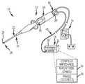
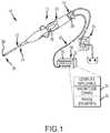
- FIG. 1is a diagrammatic view of an RF ablation embodiment having complex impedance compensation in accordance with the present invention.
- FIG. 2is a simplified block diagram showing, in greater detail, the complex impedance compensation apparatus of FIG. 1 .
- FIG. 3is a flow chart diagram showing a method for complex impedance compensation in accordance with the present invention.
- FIG. 4is a simplified diagrammatic and block diagram of an apparatus for determining a tissue type in accordance with the present invention.
- FIG. 5is a flow chart diagram showing a method for determining a tissue type in accordance with the present invention.
- the inventionthat will be described herein includes two main aspects.
- an apparatus and method for complex impedance compensationis provided.
- the first aspect of the inventionovercomes a problem described in the Background, namely, changes in the measured complex impedance that are observed but which are due to changes in the configuration of the equipment, namely the connecting, such as by cable coiling and the like.
- the first aspectprovides the ability to measure the complex impedance with respect to the tissue more accurately, which, as understood by those in the art, will have many useful applications.
- an apparatus and methodis provided for determining a tissue type based on, preferably, a phase angle component and/or also a magnitude component of the tissue's complex impedance.
- the second aspect of the inventionis useful in identifying tissue during certain applications, for example, identifying scar tissue in ventricular tachycardia (VT) applications or epicardial applications for locating fat and scar tissue.
- VT ablationone of the current approaches is to ablate on the border between the scar and normal tissue to isolate the scar that triggers VT.
- epicardial RF applicationone of the important issues is to apply energy to regular tissue and avoid RF application on fat which does not create an efficacious lesion.
- Ris a resistance component
- Xis a reactance component that is based on both capacitance and inductance contributions.
- complex impedanceis taken to include a magnitude and a phase angle. Where a magnitude of the complex impedance is intended, an absolute value of Z will be denoted,
- FIG. 1is a simplified, perspective view of an exemplary system 10 for conducting a diagnostic or therapeutic function, in which the first aspect (impedance compensation) may be practiced.
- the first aspectprovides the capability to compensate for complex impedance variations due to the cable.
- the first aspectgenerally, involves deploying a circuit, one with a known complex impedance, and then measuring the complex impedance of that circuit over a first electrical connection through a cable. Any measured variations from the known, complex impedance can then be attributed to the cable.
- the connecting cablemay be a source of variation in measured complex impedance due to non-physiologic changes (e.g., cable coiling, cable being wrapped around a steel bedpost to form an inductor, etc.).
- the variation attributed to the cablecan then be cancelled out of other measurements in the same cable, for example, when making a complex impedance measurement of tissue over another electrical connection in that same cable.
- a first electrical connection, to which the compensation will be appliedis an RF ablation source connection from an RF ablation generator through a generator cable to the ablation catheter. It is typical to make an impedance measurement through this connection.
- a second electrical connection through the same cableis set up for the purposes of determining what, if any, changes in complex impedance may be due to the cable. It should be understood, however, that this configuration is exemplary in nature only, and that many other arrangements may be practiced, consistent with the teachings of the present invention.
- a system 10is shown to include a catheter 12 operably connected to a fluid source 14 , such as a pump assembly, and an energy source, such as an RF ablation generator 16 .
- the fluid source 14 and the RF ablation generator 16may serve to facilitate the operation of ablation procedures and may involve monitoring any number of chosen variables (e.g., temperature of ablation electrode, ablation energy, and position of the assembly), assisting in manipulation of the assembly during the use, and providing the requisite energy source.
- additional componentsmay be integrated into the system 10 , such as visualization, mapping and navigation components known in the art, including among other things, NavX® or other systems.
- an ablation cathetermay typically include additional electrodes (and corresponding leads), a temperature sensor (and corresponding leads), and other features as known in the art.
- the catheter 12may include a cable connector or interface 18 , a handle 20 and a shaft 22 having a proximal end 24 and a distal end 26 near which an ablation electrode 28 is disposed. It should be re-iterated that while one electrode 28 is shown, the catheter 12 may include a plurality of electrodes, and that in any event, the electrode 28 , in other embodiments (other than RF ablation) may be used for any number of diagnostic and/or therapeutic purposes. For instance, such electrodes and therefore such catheters may be used for performing ablation procedures, cardiac mapping, electrophysiological (EP) studies, and other like procedures. Accordingly, the present invention is not limited to any one type of catheter or catheter-based system or procedure.
- the fluid source 14can comprise various known assembly, including fixed volume rolling pumps, variable volume syringe pumps and other pump assembly known to those skill in the art.
- the fluid provided by fluid source 14may comprise a suitable biocompatible fluid, such as saline.
- the RF ablation generator 16may comprise conventional apparatus, such as a commercially available unit sold under the model number IBI-1500T RF Cardiac Ablation Generator, available from Irvine Biomedical, Inc. Of course, the RF ablation generator 16 can also comprise various other known energy sources.
- the RF ablation generator 16includes an RF power source 30 configured to generate an ablation signal.
- the RF ablation signalmay typically have a frequency within the range of 50 kHz and 500 kHz.
- the ablation generator 16further includes an impedance determining circuit 32 configured to determine a complex impedance of a tissue volume proximate the tip electrode 28 .
- the complex impedancemay comprise a magnitude component 34 (e.g., expressed in ohms) and a phase angle component 36 (e.g., expressed in degrees).
- the power source 30as described above, may comprise conventional components.
- the impedance determining circuit 32may also comprise conventional components known in the art, subject to the modifications described herein.
- FIG. 1further shows a circuit 38 , which in one embodiment is located in the handle of the ablation catheter 12 , and in another embodiment (circuit 38 ′) is alternatively located in the distal end of a generator cable 40 .
- circuit 38 ′both circuits 38 and 38 ′ are the same (only the location is different). Therefore, where further reference is made to circuit 38 it should be understood that such reference also applies to circuit 38 ′.
- the circuit 38 (or 38 ′)has a predetermined, known complex impedance when probed or excited by a pilot signal having a predetermined frequency.
- the predetermined frequencymay preferably be between 100 Hz and 1 MHz, more preferably between 6 kHz and 50 kHz, and still more preferably be about 20 kHz.
- the circuit 38may be one selected from the group including: a loop-back circuit (i.e., a short circuit), a series-connected resistor circuit, series-connected resistor-inductor (RL) circuit, a series-connected resistor-capacitor (RC) circuit, a series-connected resistor-inductor-capacitor (RLC) circuit, a parallel-connected RL circuit, a parallel-connected RC circuit, a parallel-connected RLC circuit or a combination of any of the foregoing.
- a loop-back circuiti.e., a short circuit
- RLseries-connected resistor-inductor
- RCseries-connected resistor-capacitor
- RLCresistor-inductor-capacitor
- the circuit 38simplifies to the loop-back circuit described above, which still satisfies the property of having a known, complex impedance (i.e., one would expect relatively low resistance with negligible phase shift for a loop-back).
- FIG. 2is a simplified block diagram showing, in greater detail, an arrangement for complex impedance compensation.
- a compensation control 42is provided, which may be integrated within the ablation generator 16 ; however, in an alternate embodiment, the compensation control 42 may be provided as a separate unit.
- FIG. 2further shows a known complex impedance block 44 (i.e., a block that provides the magnitude/phase values known for the circuit 38 ), a difference signal 46 , a first electrical connection 48 over the cable 40 and a second electrical connection 50 that is independent from the first electrical connection 48 but is also over the same cable 40 .
- the cable 40is configured generally to allow the first electrical connection 48 to be made between the RF ablation source 30 and the catheter 12 (i.e., and in turn to the ablation tip electrode 28 ).
- the first electrical connection 48is the connection for which compensation will be made.
- the cable 40is configured to allow the second electrical connection 50 to be made between the compensation control 42 and the known-impedance circuit 38 .
- the second electrical connection 50is the connection upon which the difference signal 46 (i.e., a compensation or cancellation factor) will be determined. While the second connection 50 is illustrated in exemplary fashion as having two wires, it should be understood that the invention is not so limited. More than two wires may be used to form the second electrical connection 50 , and likewise, a single wire may be employed.
- the compensation control 42is configured to generate the above-described pilot signal at the predetermined frequency for probing or exciting the circuit 38 .
- the compensation control 42is configured to measure the complex impedance of the combination of the second electrical connection 50 and the circuit 38 . Since the complex impedance of the circuit 38 is known and available in advance, the compensation control 42 is further configured to determine a difference between the measured complex impedance and the predetermined (known) complex impedance of the circuit 38 . Any difference, be it expressed in terms of a magnitude (e.g., ohms), a phase angle (e.g., degrees) or both, would then be deemed attributable to the configuration of the cable 40 .
- a magnitudee.g., ohms
- a phase anglee.g., degrees
- the compensation control 42is thus further configured to generate the difference signal 46 indicative of the difference as determined by the control 42 .
- the difference signal 46may be generated to indicate the additional X degrees lag.
- the difference signal 46is provided to the complex impedance determining circuit 32 , which is configured to use the difference signal 46 in making compensatory adjustments.
- the circuit 32is configured to use the difference signal 46 to cancel or null out cable configuration-related variations in any measured complex impedance taken over the first electrical connection 48 .
- the particulars of the difference signalmay take many forms, although it should be understood that the selected form will be coordinated with the form expected by the complex impedance determining circuit 32 .
- the compensation control 42may be a computer-implemented apparatus operating under software control.
- a controller 52(which may already be present in the ablation generator 16 if integrated) may be configured to execute pre-programmed instructions to perform the various functions described herein.
- the compensation control 42may include various controlled hardware, such as a pilot source generator to generate the pilot signal, as well as structure suitable for measuring the resultant signal induced by the application of the pilot signal over the second electrical connection 50 to the circuit 38 . These structures may comprise conventional apparatus well known to those of ordinary skill in the art.
- the difference signal 46may take the form of a compensation factor or parameter, which may be stored in a memory and available for access by the impedance determining circuit 32 . Additionally, the compensation control 42 may be further configured to update the difference signal 46 on a periodic basis, so as to provide real-time complex impedance compensation.
- the compensation control 42may be implemented completely in hardware employing various means to measure a difference in magnitude and phase (e.g., phase detector) between the measured complex impedance (i.e., the cable plus the circuit 38 ) and the predetermined known complex impedance of the circuit 38 .
- various means to measure a difference in magnitude and phasee.g., phase detector
- FIG. 3is a flowchart showing a method for complex impedance compensation in accordance with the present invention. The method begins in step 54 .
- Step 54involves the step of providing a circuit (e.g., the circuit 38 ) having a known, predetermined complex impedance at a predetermined frequency of interest (see above description of the predetermined frequency).
- the circuit 38may be located in the handle of a catheter, or in the distal end of a connecting cable.
- the criteria for locating the circuit 38is to include as much of the cable, preferably all of the cable, in the complex impedance measurement.
- the methodproceeds to step 56 .
- Step 56involves the step of probing or exciting the circuit 38 using the pilot signal at the predetermined frequency over an electrical connection (e.g., the electrical connection 50 ) in the cable 40 .
- the methodproceeds to step 58 .
- Step 58involves the step of measuring the combined complex impedance of the electrical connection 50 and the circuit 38 . The method proceeds to step 60 .
- Step 60involves the step of determining a difference between the measured complex impedance (cable plus circuit 38 ) and the predetermined, known complex impedance of the circuit 38 .
- This differencemay be a phase angle shift (degrees), a difference in magnitude (ohms), or both.
- the methodthen proceeds to step 62 .
- Step 62involves the step of using the determined difference for compensation purposes in measurements (e.g., complex impedance measurements) conducted over other electrical connections in the same cable.
- the complex impedancemay be measured through the first electrical connection using the catheter electrode. Then, the difference may be cancelled out of such other complex impedance measurement, thereby removing the effect of the cable configuration.
- an apparatus and methodfor determining tissue morphology based on a phase angle and/or additionally a magnitude of the tissue's complex impedance.
- impedanceconventionally means the magnitude Z of the complex impedance.
- RF ablationIn the context of RF ablation, which is typically conducted at around 500 kHz, a working assumption is that such procedures involve nearly purely resistive heating. However, there does exist a number of sources that contribute capacitance. At least three main sources of such capacitance include: (1) blood; (2) the subject tissue; and (3) an electrode (e.g., Pt/Ir)-electrolyte (blood or saline) interface. Additional sources of capacitance include any connecting wires as well as stray capacitance.
- a phase angleor reactance component
- the reactance due to the capacitance and inductanceis typically much smaller than the resistance, and the phase angle is relatively small as well (e.g., ⁇ 15°). Accordingly, for most conventional purposes, such as determining tissue heating for example, the assumption that RF ablation conducted at ⁇ 500 kHz or similar frequencies is resistive is adequate. However, for other purposes, such as the inventive approach for detecting a tissue type, this assumption is inadequate.
- tissue typesmay be encountered.
- regular myocardium, scar and fat tissue typesare typical of the types of tissue that can be encountered, although it should be understood that other tissue types may be appropriate for other embodiments according to the principles disclosed herein.
- the cell structure for regular myocardiumis different from that of other types of tissue considered herein such as scar and fat tissue.
- the major determinants affecting complex impedance of regular myocardial tissueare the extra-cellular and intra-cellular resistance, a gap junction conductance, and the cell membrane capacitance (already mentioned above).
- Regular myocardiumtherefore presents a moderate impedance (magnitude) and a regular phase angle value (negative).
- Scar tissueis common for ventricular tachycardia (VT) and is considered inexcitable and acellular.
- a correlationcan be made between the phase angle, on the one hand, and the tissue type, on the other hand. More specifically, based on both impedance
- a high impedance and low phase angleindicates fatty tissue.
- low impedance and low phase angleindicates a scar.
- Moderate impedance value (i.e. between fat and scar) and a high phase angle valueindicate normal myocardium. It is important to note that phase angle values in the aforementioned paragraphs are all negative, such that a high phase angle means more negative phase angle.
- phase angle ⁇in distinguishing tissue types is preferred because it exhibits a different and unique response for each tissue type: regular myocardium, scar and fat.
- may be further used as well to distinguish regular tissue from irregular tissue, or even scar from fat, based on the particular values of the impedance measurements. Normally, fat is more resistive than scar tissue and this property can be used to differentiate scar from fat.
- FIG. 4is a simplified block diagram of an apparatus 100 configured to determine a tissue type based on a phase angle and/or magnitude of a measured complex impedance of the tissue.
- the apparatus 100is configured for use with a catheter system 102 (partially illustrated) that includes a first electrode 104 .
- the catheter system 102is configured to position the first electrode 104 so as to be in contact with the body tissue whose type is to be identified.
- the magnitude and phase angle measurementsare dependent on the electrode contact level.
- the first electrode 104is preferably, although not exclusively, contemplated to be relatively small in size, such as the following (or smaller): between a Five French (5 Fr) and Ten French (10 Fr) in diameter, more preferably a Five French (5 Fr) in diameter, and between 2 and 8 mm in length.
- FIG. 4further shows a second electrode, which in a first embodiment is a reference electrode 106 , such as a ground patch or the like, that is relatively large in size compared to the first electrode 104 .
- Patch 106may be of the dispersive/indifferent electrode pad type.
- the complex impedance measurement being madereflects the properties of the tissue near and around the first electrode 104 .
- the second electrodemay be another relatively small electrode, such as a tip electrode 108 or the like, shown in phantom line in FIG. 4 .
- the second electrode 108may be of the same configuration as the first electrode 104 .
- the complex impedance measurement being madereflects the properties of the tissue between the first and second electrodes 104 , 108 .
- additional, relatively small electrodes similar to electrode 104may be further included.
- the apparatus 100includes an excitation signal source 110 , a complex impedance measurement block 112 , and a tissue type identification logic block 114 configured to determine and output a tissue type 116 .
- the excitation signal source 110is coupled, effectively, across the first and second electrodes 104 and 106 (or alternatively 108 ) and is configured to generate the excitation signal used in determining the complex impedance. More particularly, the excitation signal, when applied across the electrodes, will produce a corresponding induced signal whose characteristics will be determined by, and thus be indicative of, the properties of the tissue under test.
- the excitation signalhas a predetermined frequency preferably between about 20 kHz or greater and 1000 kHz or less, and more preferably between about 50 kHz or greater and 500 kHz or less.
- the excitation signal source 110may comprise conventional apparatus for generating such a signal (e.g., may be either a constant voltage or current at the predetermined frequency).
- the complex impedance measurement block 112is coupled, effectively, across the first and second electrodes 104 and 106 (or alternatively 108 ) and is configured to determine a complex impedance therebetween, based on the measurement of the induced signal, in view of the applied excitation signal.
- the block 112may comprise conventional apparatus for performing such measurements, in view of the selected nature and format of the applied excitation signal.
- the source 110 and the measurement block 112may be integrated (e.g., like an LCR meter).
- the block 114is configured to identify one of a plurality of candidate tissue types based on at least one of the phase angle and/or magnitude of the tissue's complex impedance.
- the block 114is further configured to produce an output 116 reporting the identified tissue type.
- the block 114may be implemented with conventional apparatus known to those of ordinary skill in the art, and may be a computer-implemented apparatus (a computer-based controller not shown) configured to operate in accord with pre-programmed instructions and data.
- the block 114may thus be preconfigured to include a data structure (data structure not shown) and/or logic reflecting the relationship(s) between tissue type, on the one hand, and the expected phase angles and/or magnitudes on the other hand, such as illustrated in Table 1 for regular myocardium, scar and fat.
- the plurality of candidate tissue typesincludes regular myocardium, scar and fat as particularly set forth in Table 1.
- Practicing this aspect of the invention in softwarewould require no more than ordinary skill in the art, in view of this enabling disclosure describing the functions to be performed.
- other implementationsare possible, consistent with the teachings disclosed herein.
- FIG. 5is a flowchart diagram of a method of determining a tissue type. The method begins in step 118 .
- Step 118involves the step of providing a first electrode (e.g., first electrode 104 ) in adequate contact with tissue where the tissue may be one of a plurality of expected, candidate tissue types. Step 118 also involves providing a second electrode, such a reference electrode patch 106 or alternatively the second electrode 108 (as described above). The method then proceeds to step 120 .
- a first electrodee.g., first electrode 104
- second electrodesuch as a reference electrode patch 106 or alternatively the second electrode 108 (as described above). The method then proceeds to step 120 .
- Step 120involves the step of measuring a complex impedance between the first and second electrodes using an excitation signal having a predetermined frequency. Step 120 may include the substep of selecting a value defining what specific frequency to use, the particulars of which have been described above. Additionally, the complex impedance comprises a magnitude (“impedance”)
- Step 122involves the step of identifying one of the plurality of candidate tissue types based on at least one of the magnitude and/or phase angle.
- the phase angle ⁇is the preferred, primary parameter.
- may be employed as a secondary parameter, all as described above in detail.
- Step 122may further include the substep of reporting the identified tissue type.
- joinder referencesdo not necessarily infer that two elements are directly connected and in fixed relation to each other. It is intended that all matter contained in the above description or shown in the accompanying drawings shall be interpreted as illustrative only and not limiting. Changes in detail or structure may be made without departing from the spirit of the invention as defined in the appended claims.
Landscapes
- Health & Medical Sciences (AREA)
- Life Sciences & Earth Sciences (AREA)
- Biomedical Technology (AREA)
- Molecular Biology (AREA)
- Radiology & Medical Imaging (AREA)
- Biophysics (AREA)
- Pathology (AREA)
- Engineering & Computer Science (AREA)
- Nuclear Medicine, Radiotherapy & Molecular Imaging (AREA)
- Heart & Thoracic Surgery (AREA)
- Medical Informatics (AREA)
- Physics & Mathematics (AREA)
- Surgery (AREA)
- Animal Behavior & Ethology (AREA)
- General Health & Medical Sciences (AREA)
- Public Health (AREA)
- Veterinary Medicine (AREA)
- Measurement And Recording Of Electrical Phenomena And Electrical Characteristics Of The Living Body (AREA)
- Surgical Instruments (AREA)
Abstract
Description
Z=R+jX (1)
Z=|Z|<ϕ (2)
|Z|=√{square root over (R2+X2)} (3)
tan ϕ=X/R (4)
| TABLE 1 | ||
| Magnitude (Impedance) |Z| | Phase Angle ϕ | |
| Regular myocardium | Medium | High |
| Scar/ischemia | Low | Low |
| Fat | High | Low |
Claims (14)
Priority Applications (1)
| Application Number | Priority Date | Filing Date | Title |
|---|---|---|---|
| US13/584,368US10555685B2 (en) | 2007-12-28 | 2012-08-13 | Method and apparatus for determining tissue morphology based on phase angle |
Applications Claiming Priority (2)
| Application Number | Priority Date | Filing Date | Title |
|---|---|---|---|
| US11/966,320US8290578B2 (en) | 2007-12-28 | 2007-12-28 | Method and apparatus for complex impedance compensation |
| US13/584,368US10555685B2 (en) | 2007-12-28 | 2012-08-13 | Method and apparatus for determining tissue morphology based on phase angle |
Related Parent Applications (1)
| Application Number | Title | Priority Date | Filing Date |
|---|---|---|---|
| US11/966,320DivisionUS8290578B2 (en) | 2007-12-28 | 2007-12-28 | Method and apparatus for complex impedance compensation |
Publications (2)
| Publication Number | Publication Date |
|---|---|
| US20130023784A1 US20130023784A1 (en) | 2013-01-24 |
| US10555685B2true US10555685B2 (en) | 2020-02-11 |
Family
ID=40799348
Family Applications (2)
| Application Number | Title | Priority Date | Filing Date |
|---|---|---|---|
| US11/966,320Active2028-05-09US8290578B2 (en) | 2007-12-28 | 2007-12-28 | Method and apparatus for complex impedance compensation |
| US13/584,368Expired - Fee RelatedUS10555685B2 (en) | 2007-12-28 | 2012-08-13 | Method and apparatus for determining tissue morphology based on phase angle |
Family Applications Before (1)
| Application Number | Title | Priority Date | Filing Date |
|---|---|---|---|
| US11/966,320Active2028-05-09US8290578B2 (en) | 2007-12-28 | 2007-12-28 | Method and apparatus for complex impedance compensation |
Country Status (2)
| Country | Link |
|---|---|
| US (2) | US8290578B2 (en) |
| WO (1) | WO2009085457A1 (en) |
Families Citing this family (40)
| Publication number | Priority date | Publication date | Assignee | Title |
|---|---|---|---|---|
| US8403925B2 (en) | 2006-12-06 | 2013-03-26 | St. Jude Medical, Atrial Fibrillation Division, Inc. | System and method for assessing lesions in tissue |
| US9254163B2 (en) | 2005-12-06 | 2016-02-09 | St. Jude Medical, Atrial Fibrillation Division, Inc. | Assessment of electrode coupling for tissue ablation |
| US10362959B2 (en) | 2005-12-06 | 2019-07-30 | St. Jude Medical, Atrial Fibrillation Division, Inc. | System and method for assessing the proximity of an electrode to tissue in a body |
| US8603084B2 (en) | 2005-12-06 | 2013-12-10 | St. Jude Medical, Atrial Fibrillation Division, Inc. | System and method for assessing the formation of a lesion in tissue |
| US8406866B2 (en) | 2005-12-06 | 2013-03-26 | St. Jude Medical, Atrial Fibrillation Division, Inc. | System and method for assessing coupling between an electrode and tissue |
| US8998890B2 (en) | 2005-12-06 | 2015-04-07 | St. Jude Medical, Atrial Fibrillation Division, Inc. | Assessment of electrode coupling for tissue ablation |
| BRPI0621017A2 (en) | 2005-12-06 | 2011-11-29 | St Jude Medical Atrial Fibrill Div | tissue ablation electrode junction evaluation |
| US9492226B2 (en)* | 2005-12-06 | 2016-11-15 | St. Jude Medical, Atrial Fibrillation Division, Inc. | Graphical user interface for real-time RF lesion depth display |
| US9204927B2 (en) | 2009-05-13 | 2015-12-08 | St. Jude Medical, Atrial Fibrillation Division, Inc. | System and method for presenting information representative of lesion formation in tissue during an ablation procedure |
| US8290578B2 (en) | 2007-12-28 | 2012-10-16 | St. Jude Medical, Atrial Fibrillation Division, Inc. | Method and apparatus for complex impedance compensation |
| US8961417B2 (en)* | 2008-01-04 | 2015-02-24 | Texas Heart Institute | Catheter with electrodes for impedance and/or conduction velocity measurement |
| US9078627B2 (en) | 2008-01-04 | 2015-07-14 | Texas Heart Institute | Introducer sheath with electrodes |
| WO2010093603A1 (en) | 2009-02-11 | 2010-08-19 | Boston Scientific Scimed, Inc. | Insulated ablation catheter devices and methods of use |
| US8986303B2 (en)* | 2010-11-09 | 2015-03-24 | Biosense Webster, Inc. | Catheter with liquid-cooled control handle |
| US9603659B2 (en) | 2011-09-14 | 2017-03-28 | Boston Scientific Scimed Inc. | Ablation device with ionically conductive balloon |
| JP2015506234A (en) | 2012-01-10 | 2015-03-02 | ボストン サイエンティフィック サイムド,インコーポレイテッドBoston Scientific Scimed,Inc. | Electrophysiology system |
| JP2016502885A (en) | 2012-12-20 | 2016-02-01 | ボストン サイエンティフィック サイムド,インコーポレイテッドBoston Scientific Scimed,Inc. | Real-time feedback of electrode contact during mapping |
| US9289145B2 (en) | 2013-12-05 | 2016-03-22 | Medtronic, Inc. | Identification of abnormal cardiac substrate during left-ventricular pacing |
| DK3122414T3 (en) | 2014-03-26 | 2021-05-31 | Venclose Inc | Cable unit |
| GB201417963D0 (en)* | 2014-10-10 | 2014-11-26 | Univ Oslo Hf | Measurement of impedance of body tissue |
| JP2017529169A (en) | 2014-10-13 | 2017-10-05 | ボストン サイエンティフィック サイムド,インコーポレイテッドBoston Scientific Scimed,Inc. | Tissue diagnosis and treatment using mini-electrodes |
| WO2016065337A1 (en) | 2014-10-24 | 2016-04-28 | Boston Scientific Scimed Inc. | Medical devices with a flexible electrode assembly coupled to an ablation tip |
| WO2016081611A1 (en) | 2014-11-19 | 2016-05-26 | Advanced Cardiac Therapeutics, Inc. | High-resolution mapping of tissue with pacing |
| JP6725178B2 (en) | 2014-11-19 | 2020-07-15 | エピックス セラピューティクス,インコーポレイテッド | Ablation apparatus, systems and methods using high resolution electrode assemblies |
| JP6825789B2 (en) | 2014-11-19 | 2021-02-03 | エピックス セラピューティクス,インコーポレイテッド | Systems and methods for high resolution mapping of tissues |
| US9743854B2 (en) | 2014-12-18 | 2017-08-29 | Boston Scientific Scimed, Inc. | Real-time morphology analysis for lesion assessment |
| US9636164B2 (en) | 2015-03-25 | 2017-05-02 | Advanced Cardiac Therapeutics, Inc. | Contact sensing systems and methods |
| US10182742B2 (en) | 2015-04-02 | 2019-01-22 | Medtronic Ablation Frontiers Llc | Tissue contact sensing with a multi electrode ablation catheter |
| US10143399B2 (en) | 2015-04-02 | 2018-12-04 | Medtronic Ablation Frontiers Llc | Tissue contact sensing with a multi electrode ablation catheter |
| CN109069840B (en) | 2016-02-04 | 2022-03-15 | 心脏起搏器股份公司 | Delivery system with force sensor for leadless cardiac devices |
| WO2017160808A1 (en) | 2016-03-15 | 2017-09-21 | Advanced Cardiac Therapeutics, Inc. | Improved devices, systems and methods for irrigated ablation |
| CN110809448B (en) | 2017-04-27 | 2022-11-25 | Epix疗法公司 | Determining properties of contact between catheter tip and tissue |
| WO2019020809A1 (en)* | 2017-07-28 | 2019-01-31 | Scandinavian Chemotech Ab | A device, e.g. a dynamic electro enhanced pain control (deepc) device, for delivery of electrical pulses to a desired body part of a mammal |
| US10856768B2 (en) | 2018-01-25 | 2020-12-08 | Biosense Webster (Israel) Ltd. | Intra-cardiac scar tissue identification using impedance sensing and contact measurement |
| US10686715B2 (en) | 2018-05-09 | 2020-06-16 | Biosig Technologies, Inc. | Apparatus and methods for removing a large-signal voltage offset from a biomedical signal |
| CN118648971A (en) | 2019-05-09 | 2024-09-17 | 捷锐士阿希迈公司(以奥林巴斯美国外科技术名义) | Surgical System |
| CN111407273B (en)* | 2020-03-13 | 2023-10-20 | 芯海科技(深圳)股份有限公司 | Human body impedance measuring method, device, electronic equipment and storage medium |
| CR20230475A (en) | 2021-04-07 | 2024-01-19 | Btl Medical Dev A S | Pulsed field ablation device and method |
| EP4366637B1 (en) | 2021-07-06 | 2025-06-25 | BTL Medical Development A.S. | Pulsed field ablation device |
| IL319700A (en) | 2022-10-05 | 2025-05-01 | Btl Medical Dev A S | Pulsed field ablation device and method |
Citations (208)
| Publication number | Priority date | Publication date | Assignee | Title |
|---|---|---|---|---|
| US2184511A (en) | 1937-10-28 | 1939-12-26 | Samuel M Bagno | Method and apparatus for measuring impedance |
| US3316896A (en) | 1962-10-18 | 1967-05-02 | Thomasset Auguste Louis | Apparatus and methods for the measure of the electrical impedance of living organisms |
| US3949736A (en) | 1974-07-15 | 1976-04-13 | Vyvojova A Provozni Zakladna Vyzkumnych Ustavu | Circuit for automatically deriving and measuring relative voltages associated with impedance components of a biological object |
| JPS585491A (en) | 1981-07-02 | 1983-01-12 | Janome Seimitsu Kogyo Kk | Manufacture of change-over valve of fluid rotary machine |
| US4641649A (en) | 1985-10-30 | 1987-02-10 | Rca Corporation | Method and apparatus for high frequency catheter ablation |
| US5230349A (en) | 1988-11-25 | 1993-07-27 | Sensor Electronics, Inc. | Electrical heating catheter |
| US5257635A (en) | 1988-11-25 | 1993-11-02 | Sensor Electronics, Inc. | Electrical heating catheter |
| US5297549A (en) | 1992-09-23 | 1994-03-29 | Endocardial Therapeutics, Inc. | Endocardial mapping system |
| US5311866A (en) | 1992-09-23 | 1994-05-17 | Endocardial Therapeutics, Inc. | Heart mapping catheter |
| US5341807A (en) | 1992-06-30 | 1994-08-30 | American Cardiac Ablation Co., Inc. | Ablation catheter positioning system |
| US5366896A (en) | 1991-07-30 | 1994-11-22 | University Of Virginia Alumni Patents Foundation | Robotically operated laboratory system |
| US5423808A (en) | 1991-11-08 | 1995-06-13 | Ep Technologies, Inc. | Systems and methods for radiofrequency ablation with phase sensitive power detection |
| US5429131A (en) | 1994-02-25 | 1995-07-04 | The Regents Of The University Of California | Magnetized electrode tip catheter |
| US5447529A (en) | 1994-01-28 | 1995-09-05 | Philadelphia Heart Institute | Method of using endocardial impedance for determining electrode-tissue contact, appropriate sites for arrhythmia ablation and tissue heating during ablation |
| US5462544A (en) | 1993-05-05 | 1995-10-31 | Energy Life System Corporation | Continuous heart tissue mapping and lasing catheter |
| US5546940A (en) | 1994-01-28 | 1996-08-20 | Ep Technologies, Inc. | System and method for matching electrical characteristics and propagation velocities in cardiac tissue to locate potential ablation sites |
| US5582609A (en) | 1993-10-14 | 1996-12-10 | Ep Technologies, Inc. | Systems and methods for forming large lesions in body tissue using curvilinear electrode elements |
| US5588432A (en) | 1988-03-21 | 1996-12-31 | Boston Scientific Corporation | Catheters for imaging, sensing electrical potentials, and ablating tissue |
| US5630034A (en) | 1994-04-05 | 1997-05-13 | Hitachi, Ltd. | Three-dimensional image producing method and apparatus |
| US5659624A (en) | 1995-09-01 | 1997-08-19 | Fazzari; Rodney J. | High speed mass flow food sorting appartus for optically inspecting and sorting bulk food products |
| US5657755A (en) | 1993-03-11 | 1997-08-19 | Desai; Jawahar M. | Apparatus and method for cardiac ablation |
| US5688267A (en) | 1995-05-01 | 1997-11-18 | Ep Technologies, Inc. | Systems and methods for sensing multiple temperature conditions during tissue ablation |
| US5697377A (en) | 1995-11-22 | 1997-12-16 | Medtronic, Inc. | Catheter mapping system and method |
| US5702386A (en) | 1991-11-08 | 1997-12-30 | Ep Technologies, Inc. | Non-linear control systems and methods for heating and ablating body tissue |
| US5718241A (en) | 1995-06-07 | 1998-02-17 | Biosense, Inc. | Apparatus and method for treating cardiac arrhythmias with no discrete target |
| US5722402A (en) | 1994-10-11 | 1998-03-03 | Ep Technologies, Inc. | Systems and methods for guiding movable electrode elements within multiple-electrode structures |
| US5730127A (en) | 1993-12-03 | 1998-03-24 | Avitall; Boaz | Mapping and ablation catheter system |
| US5759159A (en) | 1996-09-25 | 1998-06-02 | Ormco Corporation | Method and apparatus for apical detection with complex impedance measurement |
| US5782900A (en) | 1997-06-23 | 1998-07-21 | Irvine Biomedical, Inc. | Catheter system having safety means |
| US5800350A (en)* | 1993-11-01 | 1998-09-01 | Polartechnics, Limited | Apparatus for tissue type recognition |
| US5810742A (en)* | 1994-10-24 | 1998-09-22 | Transcan Research & Development Co., Ltd. | Tissue characterization based on impedance images and on impedance measurements |
| US5814043A (en) | 1996-09-06 | 1998-09-29 | Mentor Ophthalmics, Inc. | Bipolar electrosurgical device |
| WO1998046149A1 (en) | 1997-04-11 | 1998-10-22 | Taccor, Inc. | Steerable catheter with rotatable tip electrode and method of use |
| US5836943A (en) | 1996-08-23 | 1998-11-17 | Team Medical, L.L.C. | Electrosurgical generator |
| US5836990A (en) | 1997-09-19 | 1998-11-17 | Medtronic, Inc. | Method and apparatus for determining electrode/tissue contact |
| US5837001A (en) | 1995-12-08 | 1998-11-17 | C. R. Bard | Radio frequency energy delivery system for multipolar electrode catheters |
| US5846238A (en) | 1996-01-19 | 1998-12-08 | Ep Technologies, Inc. | Expandable-collapsible electrode structures with distal end steering or manipulation |
| US5904709A (en) | 1996-04-17 | 1999-05-18 | The United States Of America As Represented By The Administrator Of The National Aeronautics And Space Administration | Microwave treatment for cardiac arrhythmias |
| US5944022A (en) | 1997-04-28 | 1999-08-31 | American Cardiac Ablation Co. Inc. | Catheter positioning system |
| US5954665A (en) | 1995-06-07 | 1999-09-21 | Biosense, Inc. | Cardiac ablation catheter using correlation measure |
| US6001093A (en) | 1993-10-15 | 1999-12-14 | Ep Technologies, Inc. | Systems and methods for creating long, thin lesions in body tissue |
| US6019757A (en) | 1995-07-07 | 2000-02-01 | Target Therapeutics, Inc. | Endoluminal electro-occlusion detection apparatus and method |
| US6026323A (en)* | 1997-03-20 | 2000-02-15 | Polartechnics Limited | Tissue diagnostic system |
| US6035341A (en) | 1996-10-31 | 2000-03-07 | Sensormatic Electronics Corporation | Multimedia data analysis in intelligent video information management system |
| US6063078A (en) | 1997-03-12 | 2000-05-16 | Medtronic, Inc. | Method and apparatus for tissue ablation |
| US6129669A (en) | 1998-05-22 | 2000-10-10 | Scimed Life Systems, Inc. | Systems and methods for assessing stability of an ablation electrode in contact with heart tissue |
| WO2000078239A2 (en) | 1999-06-17 | 2000-12-28 | Cardiac Pacemakers, Inc. | Rf ablation apparatus and method having electrode/tissue contact assessment scheme and electrocardiogram filtering |
| US6171304B1 (en) | 1997-04-04 | 2001-01-09 | 3M Innovative Properties Company | Method and apparatus for controlling contact of biomedical electrodes with patient skin |
| US6179824B1 (en) | 1993-05-10 | 2001-01-30 | Arthrocare Corporation | System and methods for electrosurgical restenosis of body lumens |
| US6206874B1 (en) | 1998-04-08 | 2001-03-27 | Siemens-Elema Ab | Apparatus and method for locating electrically active sites with an animal |
| US6217576B1 (en) | 1997-05-19 | 2001-04-17 | Irvine Biomedical Inc. | Catheter probe for treating focal atrial fibrillation in pulmonary veins |
| US6217574B1 (en) | 1998-12-03 | 2001-04-17 | Cordis Webster | System and method for measuring subsurface temperature of tissue during ablation |
| US6221070B1 (en) | 1996-10-18 | 2001-04-24 | Irvine Biomedical, Inc. | Steerable ablation catheter system having disposable shaft |
| US6226542B1 (en) | 1998-07-24 | 2001-05-01 | Biosense, Inc. | Three-dimensional reconstruction of intrabody organs |
| US6233476B1 (en) | 1999-05-18 | 2001-05-15 | Mediguide Ltd. | Medical positioning system |
| US6246896B1 (en) | 1998-11-24 | 2001-06-12 | General Electric Company | MRI guided ablation system |
| US6256540B1 (en) | 1994-01-28 | 2001-07-03 | Ep Technologies | Systems and methods for examining the electrical characteristic of cardiac tissue |
| US20010034501A1 (en) | 2000-03-23 | 2001-10-25 | Tom Curtis P. | Pressure sensor for therapeutic delivery device and method |
| US20010039413A1 (en) | 1998-05-05 | 2001-11-08 | Bowe Wade A. | Preformed steerable catheter with movable outer sleeve and method for use |
| US6322558B1 (en) | 1995-06-09 | 2001-11-27 | Engineering & Research Associates, Inc. | Apparatus and method for predicting ablation depth |
| US20010047129A1 (en) | 1999-05-13 | 2001-11-29 | Hall Andrew F. | Medical devices adapted for magnetic navigation with magnetic fields and gradients |
| US20010051774A1 (en) | 2000-02-28 | 2001-12-13 | Peter Littrup | Multidimensional bioelectrical tissue analyzer |
| US6337994B1 (en) | 1998-04-30 | 2002-01-08 | Johns Hopkins University | Surgical needle probe for electrical impedance measurements |
| US20020013537A1 (en)* | 2000-07-19 | 2002-01-31 | Rock Emilio Sacristan | Impedance spectroscopy system and catheter for ischemic mucosal damage monitoring in hollow viscous organs |
| US20020022836A1 (en) | 1999-03-05 | 2002-02-21 | Gyrus Medical Limited | Electrosurgery system |
| US20020049375A1 (en) | 1999-05-18 | 2002-04-25 | Mediguide Ltd. | Method and apparatus for real time quantitative three-dimensional image reconstruction of a moving organ and intra-body navigation |
| US20020068931A1 (en) | 1999-06-04 | 2002-06-06 | Engineering & Research Associates, Inc. | Apparatus and method for real time determination of materials' electrical properties |
| US20020072686A1 (en) | 2000-05-18 | 2002-06-13 | Nuvasive, Inc. | Tissue discrimination and applications in medical procedures |
| US20020077627A1 (en) | 2000-07-25 | 2002-06-20 | Johnson Theodore C. | Method for detecting and treating tumors using localized impedance measurement |
| US6423057B1 (en) | 1999-01-25 | 2002-07-23 | The Arizona Board Of Regents On Behalf Of The University Of Arizona | Method and apparatus for monitoring and controlling tissue temperature and lesion formation in radio-frequency ablation procedures |
| US6427089B1 (en) | 1999-02-19 | 2002-07-30 | Edward W. Knowlton | Stomach treatment apparatus and method |
| US20020120188A1 (en) | 2000-12-21 | 2002-08-29 | Brock David L. | Medical mapping system |
| US6445952B1 (en) | 2000-05-18 | 2002-09-03 | Medtronic, Inc. | Apparatus and method for detecting micro-dislodgment of a pacing lead |
| US6443894B1 (en) | 1999-09-29 | 2002-09-03 | Acuson Corporation | Medical diagnostic ultrasound system and method for mapping surface data for three dimensional imaging |
| US20020123749A1 (en) | 2001-03-01 | 2002-09-05 | Jain Mudit K. | Ablation catheter with transducer for providing one or more of pressure, temperature and fluid flow data for use in controlling ablation therapy |
| US6456864B1 (en) | 1994-10-11 | 2002-09-24 | Ep Technologies, Inc. | Systems and methods for guiding movable electrode elements within multiple-electrode structures |
| US20020151887A1 (en) | 1999-03-09 | 2002-10-17 | Stern Roger A. | Handpiece for treatment of tissue |
| US6468271B1 (en) | 1999-02-24 | 2002-10-22 | Scimed Life Systems, Inc. | Device and method for percutaneous myocardial revascularization |
| US6471693B1 (en) | 1999-09-10 | 2002-10-29 | Cryocath Technologies Inc. | Catheter and system for monitoring tissue contact |
| US6475215B1 (en) | 2000-10-12 | 2002-11-05 | Naim Erturk Tanrisever | Quantum energy surgical device and method |
| US20020177847A1 (en) | 2001-03-30 | 2002-11-28 | Long Gary L. | Endoscopic ablation system with flexible coupling |
| US6490474B1 (en) | 1997-08-01 | 2002-12-03 | Cardiac Pathways Corporation | System and method for electrode localization using ultrasound |
| US6498944B1 (en) | 1996-02-01 | 2002-12-24 | Biosense, Inc. | Intrabody measurement |
| US6507751B2 (en) | 1997-11-12 | 2003-01-14 | Stereotaxis, Inc. | Method and apparatus using shaped field of repositionable magnet to guide implant |
| US6511478B1 (en) | 2000-06-30 | 2003-01-28 | Scimed Life Systems, Inc. | Medical probe with reduced number of temperature sensor wires |
| US20030028183A1 (en) | 2001-03-27 | 2003-02-06 | Sanchez Javier E. | Electrophysiologic measure of endpoints for ablation lesions created in fibrillating substrates |
| US20030045871A1 (en) | 2001-08-31 | 2003-03-06 | Jain Mudit K. | Ablation system with selectable current path means |
| US20030060696A1 (en) | 2001-06-15 | 2003-03-27 | Skladnev Victor Nickolaevich | Apparatus for tissue type recognition using multiple measurement techniques |
| US20030065364A1 (en) | 2001-09-28 | 2003-04-03 | Ethicon, Inc. | Expandable intracardiac return electrode and method of use |
| US6546270B1 (en) | 2000-07-07 | 2003-04-08 | Biosense, Inc. | Multi-electrode catheter, system and method |
| US6558382B2 (en) | 2000-04-27 | 2003-05-06 | Medtronic, Inc. | Suction stabilized epicardial ablation devices |
| US20030093069A1 (en) | 1996-01-19 | 2003-05-15 | Ep Technologies, Inc. | Expandable-collapsible electrode structures made of electrically conductive material |
| US20030093067A1 (en) | 2001-11-09 | 2003-05-15 | Scimed Life Systems, Inc. | Systems and methods for guiding catheters using registered images |
| US6569160B1 (en) | 2000-07-07 | 2003-05-27 | Biosense, Inc. | System and method for detecting electrode-tissue contact |
| US20030100823A1 (en) | 2000-03-29 | 2003-05-29 | Daryl Kipke | Device for creating a neural interface and method for making same |
| US6575969B1 (en) | 1995-05-04 | 2003-06-10 | Sherwood Services Ag | Cool-tip radiofrequency thermosurgery electrode system for tumor ablation |
| US20030130711A1 (en) | 2001-09-28 | 2003-07-10 | Pearson Robert M. | Impedance controlled tissue ablation apparatus and method |
| US6605082B2 (en) | 2000-07-03 | 2003-08-12 | Olympus Optical Co., Ltd. | Thermal treatment apparatus |
| US20030187430A1 (en) | 2002-03-15 | 2003-10-02 | Vorisek James C. | System and method for measuring power at tissue during RF ablation |
| US6652518B2 (en) | 2001-09-28 | 2003-11-25 | Ethicon, Inc. | Transmural ablation tool and method |
| US6663622B1 (en) | 2000-02-11 | 2003-12-16 | Iotek, Inc. | Surgical devices and methods for use in tissue ablation procedures |
| US20040006337A1 (en) | 2000-05-12 | 2004-01-08 | Michael Nasab | Multi-channnel rf energy delivery with coagulum reduction |
| US6676654B1 (en) | 1997-08-29 | 2004-01-13 | Asah Medico A/S | Apparatus for tissue treatment and having a monitor for display of tissue features |
| US6683280B1 (en) | 2003-03-12 | 2004-01-27 | Jeffrey S. Wofford | Apparatus and method for prosthesis securement |
| US6690963B2 (en) | 1995-01-24 | 2004-02-10 | Biosense, Inc. | System for determining the location and orientation of an invasive medical instrument |
| US20040030258A1 (en) | 2000-10-09 | 2004-02-12 | Williams Christopher Edward | Sensor assembly for monitoring an infant brain |
| US20040044292A1 (en) | 2002-08-30 | 2004-03-04 | Pioneer Corporation | System, method, program, and medium for measuring heart rate |
| US6712074B2 (en) | 1998-02-19 | 2004-03-30 | Curon Medical, Inc. | Systems and methods for forming composite lesions to treat dysfunction in sphincters and adjoining tissue regions |
| US20040078036A1 (en) | 2002-10-21 | 2004-04-22 | Yaron Keidar | Real-time monitoring and mapping of ablation lesion formation in the heart |
| US20040078058A1 (en) | 2002-07-22 | 2004-04-22 | Nils Holmstrom | Heart stimulator with stimulation controlled by analysis of an average impedance morphology curve |
| US20040082946A1 (en) | 2002-10-24 | 2004-04-29 | Valley Forge Scientific | Electrosurgical generator apparatus |
| US20040087975A1 (en) | 1999-04-09 | 2004-05-06 | Evalve, Inc. | Fixation device delivery catheter, systems and methods of use |
| US20040097806A1 (en) | 2002-11-19 | 2004-05-20 | Mark Hunter | Navigation system for cardiac therapies |
| US6755790B2 (en) | 2002-10-14 | 2004-06-29 | Medtronic, Inc. | Transseptal access tissue thickness sensing dilator devices and methods for fabricating and using same |
| US20040147920A1 (en) | 2002-10-21 | 2004-07-29 | Yaron Keidar | Prediction and assessment of ablation of cardiac tissue |
| US6780182B2 (en) | 2002-05-23 | 2004-08-24 | Adiana, Inc. | Catheter placement detection system and operator interface |
| US6813515B2 (en)* | 2002-01-04 | 2004-11-02 | Dune Medical Devices Ltd. | Method and system for examining tissue according to the dielectric properties thereof |
| EP1472976A1 (en) | 2003-04-29 | 2004-11-03 | Biosense Webster, Inc. | Device for performing a medical procedure |
| JP3585491B2 (en) | 1993-04-30 | 2004-11-04 | メディカル サイエンティフィク インコーポレイテッド | Impedance feedback electrosurgical system |
| US20040243018A1 (en) | 2002-11-27 | 2004-12-02 | Z-Tech (Canada) Inc. | Apparatus and method for determining adequacy of electrode-to-skin contact and electrode quality for bioelectrical measurements |
| US20040243181A1 (en) | 2003-05-31 | 2004-12-02 | Tyrell, Inc. | Methods and devices for the treatment of skin lesions |
| US20040267252A1 (en) | 2003-06-30 | 2004-12-30 | Ethicon, Inc. | Multi-modality ablation device |
| US6840938B1 (en) | 2000-12-29 | 2005-01-11 | Intuitive Surgical, Inc. | Bipolar cauterizing instrument |
| US20050010263A1 (en) | 2001-07-27 | 2005-01-13 | Patrick Schauerte | Neurostimulation unit for immobilizing the heart during cardiosurgical operations |
| US20050054944A1 (en) | 2003-09-05 | 2005-03-10 | Tanita Corporation | Bioelectrical impedance measuring apparatus |
| US20050065507A1 (en) | 2003-09-19 | 2005-03-24 | Baylis Medical Company Inc. | Surgical perforation device with curve |
| US6917834B2 (en) | 1997-12-03 | 2005-07-12 | Boston Scientific Scimed, Inc. | Devices and methods for creating lesions in endocardial and surrounding tissue to isolate focal arrhythmia substrates |
| US6918876B1 (en) | 1999-10-29 | 2005-07-19 | Kabushiki Kaisha Toshiba | Ultrasound diagnostic apparatus |
| US6926669B1 (en)* | 2000-10-10 | 2005-08-09 | Medtronic, Inc. | Heart wall ablation/mapping catheter and method |
| US6950689B1 (en) | 1998-08-03 | 2005-09-27 | Boston Scientific Scimed, Inc. | Dynamically alterable three-dimensional graphical model of a body region |
| US20050222554A1 (en) | 2004-03-05 | 2005-10-06 | Wallace Daniel T | Robotic catheter system |
| JP2005279256A (en) | 2004-03-01 | 2005-10-13 | Tanita Corp | Body composition measuring device |
| US6964867B2 (en) | 2001-03-16 | 2005-11-15 | Irm, Llc | Method and apparatus for performing multiple processing steps on a sample in a single vessel |
| US20060015033A1 (en) | 2004-07-19 | 2006-01-19 | Blakley Daniel R | ECG electrode characterization and compensation |
| US20060011669A1 (en) | 2004-07-17 | 2006-01-19 | The Hardway, Llc | Dispenser protector device and method |
| US6993384B2 (en) | 2001-12-04 | 2006-01-31 | Advanced Bionics Corporation | Apparatus and method for determining the relative position and orientation of neurostimulation leads |
| US20060085049A1 (en) | 2004-10-20 | 2006-04-20 | Nervonix, Inc. | Active electrode, bio-impedance based, tissue discrimination system and methods of use |
| US20060173251A1 (en) | 2005-01-07 | 2006-08-03 | Assaf Govari | Current-based position sensing |
| US20060200049A1 (en) | 2005-03-04 | 2006-09-07 | Giovanni Leo | Medical apparatus system having optical fiber load sensing capability |
| US7106043B1 (en)* | 2002-09-17 | 2006-09-12 | Bioluminate, Inc. | Low capacitance measurement probe |
| US20060235286A1 (en)* | 2005-03-28 | 2006-10-19 | Minnow Medical, Llc | Tuned RF energy for selective treatment of atheroma and other target tissues and/or structures |
| US20070016006A1 (en) | 2005-05-27 | 2007-01-18 | Yehoshua Shachar | Apparatus and method for shaped magnetic field control for catheter, guidance, control, and imaging |
| US20070055142A1 (en) | 2003-03-14 | 2007-03-08 | Webler William E | Method and apparatus for image guided position tracking during percutaneous procedures |
| US7197354B2 (en) | 2004-06-21 | 2007-03-27 | Mediguide Ltd. | System for determining the position and orientation of a catheter |
| US20070073179A1 (en) | 2005-09-15 | 2007-03-29 | St. Jude Medical, Atrial Fibrillation Division, Inc. | System and Method for Three Dimensional Mapping of Electrophysiology Information |
| US20070083193A1 (en) | 2005-08-22 | 2007-04-12 | Werneth Randell L | User interface for tissue ablation system |
| US20070100332A1 (en) | 2005-10-27 | 2007-05-03 | St. Jude Medical, Atrial Fibrillation Division, Inc. | Systems and methods for electrode contact assessment |
| US20070106289A1 (en) | 2005-09-26 | 2007-05-10 | O'sullivan Martin F | System and method for monitoring esophagus proximity |
| US20070118100A1 (en) | 2005-11-22 | 2007-05-24 | General Electric Company | System and method for improved ablation of tumors |
| US20070123764A1 (en) | 2005-10-13 | 2007-05-31 | Chou Thao | Systems and Methods For Assessing Tissue Contact |
| WO2007067941A2 (en) | 2005-12-06 | 2007-06-14 | St. Jude Medical, Atrial Fibrillation Division, Inc. | Assessment of electrode coupling for tissue ablation |
| US20070161915A1 (en) | 1993-03-11 | 2007-07-12 | Desai Jawahar M | Apparatus And Method For Cardiac Ablation |
| US7263397B2 (en) | 1998-06-30 | 2007-08-28 | St. Jude Medical, Atrial Fibrillation Division, Inc. | Method and apparatus for catheter navigation and location and mapping in the heart |
| US7263395B2 (en) | 2002-01-31 | 2007-08-28 | Loughborough University Enterprises Ltd. | Venous pulse oximetry |
| US20070225558A1 (en) | 2004-05-28 | 2007-09-27 | Hauck John A | Robotic surgical system and method for surface modeling |
| US20070225593A1 (en) | 2006-03-08 | 2007-09-27 | Joshua Porath | Esophagus imaging enhancement device |
| US20070244479A1 (en) | 1992-09-23 | 2007-10-18 | St. Jude Medical, Atrial Fibrillation Division, Inc. | Electrophysiology Therapy Catheter |
| US20070255162A1 (en) | 2005-11-18 | 2007-11-01 | Marwan Abboud | Bioimpedance measurement system and method |
| US20080091193A1 (en) | 2005-05-16 | 2008-04-17 | James Kauphusman | Irrigated ablation catheter having magnetic tip for magnetic field control and guidance |
| US20080097422A1 (en) | 1998-02-19 | 2008-04-24 | Curon Medical Inc. | Graphical user interface for association with an electrode structure deployed in contact with a tissue region |
| US20080097220A1 (en) | 2006-10-23 | 2008-04-24 | Chad Allen Lieber | Apparatus and method for monitoring early formation of steam pop during ablation |
| US20080132890A1 (en) | 1992-01-07 | 2008-06-05 | Arthrocare Corporation | Electrosurgical apparatus and methods for laparoscopy |
| US7386339B2 (en) | 1999-05-18 | 2008-06-10 | Mediguide Ltd. | Medical imaging and navigation system |
| US20080183071A1 (en) | 2007-01-10 | 2008-07-31 | Mediguide Lit. | System and method for superimposing a representation of the tip of a catheter on an image acquired by a moving imager |
| US20080183189A1 (en) | 2007-01-25 | 2008-07-31 | Warsaw Orthopedic, Inc. | Surgical navigational and neuromonitoring instrument |
| US20080221440A1 (en) | 2007-03-08 | 2008-09-11 | Sync-Rx, Ltd. | Imaging and tools for use with moving organs |
| US20080234574A1 (en)* | 2004-05-26 | 2008-09-25 | Medical Device Innovations Limited | Tissue Detection and Ablation Apparatus and Apparatus and Method For Actuating a Tuner |
| US20080249536A1 (en) | 2007-02-15 | 2008-10-09 | Hansen Medical, Inc. | Interface assembly for controlling orientation of robotically controlled medical instrument |
| US20080288023A1 (en) | 2005-08-31 | 2008-11-20 | Michael Sasha John | Medical treatment using patient states, patient alerts, and hierarchical algorithms |
| US20080312713A1 (en) | 2007-06-14 | 2008-12-18 | Wilfley Brian P | System and method for determining electrode-tissue contact based on amplitude modulation of sensed signal |
| US20090012533A1 (en) | 2007-04-23 | 2009-01-08 | Hansen Medical, Inc. | Robotic instrument control system |
| US20090036794A1 (en) | 2005-12-29 | 2009-02-05 | Rikshospitalet-Radiumhospitalet Hf | Method and apparatus for determining local tissue impedance for positioning of a needle |
| US7497858B2 (en) | 2002-02-19 | 2009-03-03 | Maquet Cardiovascular Llc | Apparatus and method for assessing transmurality of a tissue ablation |
| US7536218B2 (en) | 2005-07-15 | 2009-05-19 | Biosense Webster, Inc. | Hybrid magnetic-based and impedance-based position sensing |
| WO2009065140A1 (en) | 2007-11-16 | 2009-05-22 | St. Jude Medical, Atrial Fibrillation Division, Inc. | Device and method for real-time lesion estimation during ablation |
| US20090163904A1 (en) | 2005-12-06 | 2009-06-25 | St. Jude Medical, Atrial Fibrillation Division, Inc. | System and Method for Assessing Coupling Between an Electrode and Tissue |
| US20090171235A1 (en) | 2007-12-28 | 2009-07-02 | Clint Schneider | Method and apparatus for complex impedance compensation and for determining tissue morphology based on phase angle |
| US20090171345A1 (en) | 2007-12-28 | 2009-07-02 | Miller Stephan P | System and method for measurement of an impedance using a catheter such as an ablation catheter |
| US20090177111A1 (en) | 2006-12-06 | 2009-07-09 | Miller Stephan P | System and method for displaying contact between a catheter and tissue |
| US7565613B2 (en) | 2005-12-01 | 2009-07-21 | Microsoft Corporation | User interface incorporating data ecosystem awareness |
| US20090247942A1 (en) | 2008-03-27 | 2009-10-01 | Kirschenman Mark B | Robotic catheter manipulator assembly |
| US20090247944A1 (en) | 2008-03-27 | 2009-10-01 | Kirschenman Mark B | Robotic catheter rotatable device cartridge |
| US20090247943A1 (en) | 2008-03-27 | 2009-10-01 | Kirschenman Mark B | Robotic catheter device cartridge |
| US20090248042A1 (en) | 2008-03-27 | 2009-10-01 | Kirschenman Mark B | Model catheter input device |
| US20090247993A1 (en) | 2008-03-27 | 2009-10-01 | Kirschenman Mark B | Robotic catheter system |
| WO2009120982A2 (en) | 2008-03-27 | 2009-10-01 | St. Jude Medical, Atrial Fibrillation Division, Inc. | Robotic catheter system with dynamic response |
| US7610078B2 (en) | 2005-08-26 | 2009-10-27 | Boston Scientific Scimed, Inc. | System and method of graphically generating anatomical structures using ultrasound echo information |
| US20090276002A1 (en) | 2008-04-30 | 2009-11-05 | Sommer John L | Lead-Implant Coupling Device |
| US20090275827A1 (en) | 2005-12-06 | 2009-11-05 | Aiken Robert D | System and method for assessing the proximity of an electrode to tissue in a body |
| US20090306655A1 (en) | 2008-06-09 | 2009-12-10 | Stangenes Todd R | Catheter assembly with front-loaded tip and multi-contact connector |
| US7633502B2 (en) | 2004-05-19 | 2009-12-15 | Boston Scientific Scimed, Inc. | System and method for graphically representing anatomical orifices and vessels |
| US7671871B2 (en) | 2002-06-21 | 2010-03-02 | Avid Technology, Inc. | Graphical user interface for color correction using curves |
| US20100069921A1 (en) | 2006-12-06 | 2010-03-18 | Miller Stephan P | System and method for assessing lesions in tissue |
| US20100168550A1 (en) | 2008-12-31 | 2010-07-01 | Byrd Israel A | Multiple shell construction to emulate chamber contraction with a mapping system |
| US20100168735A1 (en) | 2005-12-06 | 2010-07-01 | Don Curtis Deno | System and method for assessing coupling between an electrode and tissue |
| US20100191089A1 (en) | 2007-07-09 | 2010-07-29 | Sis Medical Ag | Method and system to detect neointima coverage of a stent |
| US7776034B2 (en) | 2005-06-15 | 2010-08-17 | St. Jude Medical, Atrial Fibrillation Division, Inc. | Ablation catheter with adjustable virtual electrode |
| US20100256558A1 (en) | 2008-03-27 | 2010-10-07 | Olson Eric S | Robotic catheter system |
| US7819870B2 (en) | 2005-10-13 | 2010-10-26 | St. Jude Medical, Atrial Fibrillation Division, Inc. | Tissue contact and thermal assessment for brush electrodes |
| US20100298823A1 (en) | 2005-12-06 | 2010-11-25 | Hong Cao | Assessment of electrode coupling for tissue ablation |
| US20110015569A1 (en) | 2008-03-27 | 2011-01-20 | Kirschenman Mark B | Robotic catheter system input device |
| US7904174B2 (en) | 2003-10-31 | 2011-03-08 | Cardiac Pacemakers, Inc. | Implantable leads permitting functional status monitoring |
| US7925349B1 (en)* | 2006-03-31 | 2011-04-12 | Pacesetter, Inc. | Tissue characterization using intracardiac impedances with an implantable lead system |
| US20110118727A1 (en) | 2005-12-06 | 2011-05-19 | Fish Jeffrey M | System and method for assessing the formation of a lesion in tissue |
| WO2011123669A1 (en) | 2010-03-31 | 2011-10-06 | St. Jude Medical, Atrial Fibrillation Division, Inc. | Intuitive user interface control for remote catheter navigation and 3d mapping and visualization systems |
| US20110313311A1 (en) | 2008-11-28 | 2011-12-22 | Impedimed Limited | Impedance measurement process |
| US20110313417A1 (en) | 2010-06-16 | 2011-12-22 | St. Jude Medical, Inc. | Ablation catheter having flexible tip with multiple flexible electrode segments |
| US20120158011A1 (en) | 2010-12-16 | 2012-06-21 | Sandhu Kulbir S | Proximity sensor interface in a robotic catheter system |
Family Cites Families (2)
| Publication number | Priority date | Publication date | Assignee | Title |
|---|---|---|---|---|
| US5836690A (en)* | 1997-12-17 | 1998-11-17 | Ultimate Environmental Mixing, Inc. | Rotatable mixing head having sealed bearings |
| US20030013071A1 (en)* | 2001-07-03 | 2003-01-16 | Thomas Richard Todd | Computerized exercise apparatus |
- 2007
- 2007-12-28USUS11/966,320patent/US8290578B2/enactiveActive
- 2008
- 2008-11-20WOPCT/US2008/084194patent/WO2009085457A1/enactiveApplication Filing
- 2012
- 2012-08-13USUS13/584,368patent/US10555685B2/ennot_activeExpired - Fee Related
Patent Citations (232)
| Publication number | Priority date | Publication date | Assignee | Title |
|---|---|---|---|---|
| US2184511A (en) | 1937-10-28 | 1939-12-26 | Samuel M Bagno | Method and apparatus for measuring impedance |
| US3316896A (en) | 1962-10-18 | 1967-05-02 | Thomasset Auguste Louis | Apparatus and methods for the measure of the electrical impedance of living organisms |
| US3949736A (en) | 1974-07-15 | 1976-04-13 | Vyvojova A Provozni Zakladna Vyzkumnych Ustavu | Circuit for automatically deriving and measuring relative voltages associated with impedance components of a biological object |
| JPS585491A (en) | 1981-07-02 | 1983-01-12 | Janome Seimitsu Kogyo Kk | Manufacture of change-over valve of fluid rotary machine |
| US4641649A (en) | 1985-10-30 | 1987-02-10 | Rca Corporation | Method and apparatus for high frequency catheter ablation |
| US5588432A (en) | 1988-03-21 | 1996-12-31 | Boston Scientific Corporation | Catheters for imaging, sensing electrical potentials, and ablating tissue |
| US5257635A (en) | 1988-11-25 | 1993-11-02 | Sensor Electronics, Inc. | Electrical heating catheter |
| US5230349A (en) | 1988-11-25 | 1993-07-27 | Sensor Electronics, Inc. | Electrical heating catheter |
| US5366896A (en) | 1991-07-30 | 1994-11-22 | University Of Virginia Alumni Patents Foundation | Robotically operated laboratory system |
| US5423808A (en) | 1991-11-08 | 1995-06-13 | Ep Technologies, Inc. | Systems and methods for radiofrequency ablation with phase sensitive power detection |
| US5702386A (en) | 1991-11-08 | 1997-12-30 | Ep Technologies, Inc. | Non-linear control systems and methods for heating and ablating body tissue |
| US20080132890A1 (en) | 1992-01-07 | 2008-06-05 | Arthrocare Corporation | Electrosurgical apparatus and methods for laparoscopy |
| US5341807A (en) | 1992-06-30 | 1994-08-30 | American Cardiac Ablation Co., Inc. | Ablation catheter positioning system |
| US5297549A (en) | 1992-09-23 | 1994-03-29 | Endocardial Therapeutics, Inc. | Endocardial mapping system |
| US5311866A (en) | 1992-09-23 | 1994-05-17 | Endocardial Therapeutics, Inc. | Heart mapping catheter |
| US20080234564A1 (en) | 1992-09-23 | 2008-09-25 | Beatty Graydon E | Electrophysiology therapy catheter |
| US20070244479A1 (en) | 1992-09-23 | 2007-10-18 | St. Jude Medical, Atrial Fibrillation Division, Inc. | Electrophysiology Therapy Catheter |
| US5657755A (en) | 1993-03-11 | 1997-08-19 | Desai; Jawahar M. | Apparatus and method for cardiac ablation |
| US20070161915A1 (en) | 1993-03-11 | 2007-07-12 | Desai Jawahar M | Apparatus And Method For Cardiac Ablation |
| JP3585491B2 (en) | 1993-04-30 | 2004-11-04 | メディカル サイエンティフィク インコーポレイテッド | Impedance feedback electrosurgical system |
| US5462544A (en) | 1993-05-05 | 1995-10-31 | Energy Life System Corporation | Continuous heart tissue mapping and lasing catheter |
| US6179824B1 (en) | 1993-05-10 | 2001-01-30 | Arthrocare Corporation | System and methods for electrosurgical restenosis of body lumens |
| US5582609A (en) | 1993-10-14 | 1996-12-10 | Ep Technologies, Inc. | Systems and methods for forming large lesions in body tissue using curvilinear electrode elements |
| US6001093A (en) | 1993-10-15 | 1999-12-14 | Ep Technologies, Inc. | Systems and methods for creating long, thin lesions in body tissue |
| US5800350A (en)* | 1993-11-01 | 1998-09-01 | Polartechnics, Limited | Apparatus for tissue type recognition |
| US5730127A (en) | 1993-12-03 | 1998-03-24 | Avitall; Boaz | Mapping and ablation catheter system |
| US5562721A (en) | 1994-01-28 | 1996-10-08 | University Of Pennsylvania | Method of using endocardial impedance for assessing tissue heating during ablation |
| US6256540B1 (en) | 1994-01-28 | 2001-07-03 | Ep Technologies | Systems and methods for examining the electrical characteristic of cardiac tissue |
| US5673704A (en) | 1994-01-28 | 1997-10-07 | Marchlinski; Francis E. | Method of using endocardial impedance for determining electrode-tissue contact |
| US5546940A (en) | 1994-01-28 | 1996-08-20 | Ep Technologies, Inc. | System and method for matching electrical characteristics and propagation velocities in cardiac tissue to locate potential ablation sites |
| US5447529A (en) | 1994-01-28 | 1995-09-05 | Philadelphia Heart Institute | Method of using endocardial impedance for determining electrode-tissue contact, appropriate sites for arrhythmia ablation and tissue heating during ablation |
| US5429131A (en) | 1994-02-25 | 1995-07-04 | The Regents Of The University Of California | Magnetized electrode tip catheter |
| US5630034A (en) | 1994-04-05 | 1997-05-13 | Hitachi, Ltd. | Three-dimensional image producing method and apparatus |
| US6456864B1 (en) | 1994-10-11 | 2002-09-24 | Ep Technologies, Inc. | Systems and methods for guiding movable electrode elements within multiple-electrode structures |
| US5722402A (en) | 1994-10-11 | 1998-03-03 | Ep Technologies, Inc. | Systems and methods for guiding movable electrode elements within multiple-electrode structures |
| US5810742A (en)* | 1994-10-24 | 1998-09-22 | Transcan Research & Development Co., Ltd. | Tissue characterization based on impedance images and on impedance measurements |
| US6690963B2 (en) | 1995-01-24 | 2004-02-10 | Biosense, Inc. | System for determining the location and orientation of an invasive medical instrument |
| US5688267A (en) | 1995-05-01 | 1997-11-18 | Ep Technologies, Inc. | Systems and methods for sensing multiple temperature conditions during tissue ablation |
| US6575969B1 (en) | 1995-05-04 | 2003-06-10 | Sherwood Services Ag | Cool-tip radiofrequency thermosurgery electrode system for tumor ablation |
| US5718241A (en) | 1995-06-07 | 1998-02-17 | Biosense, Inc. | Apparatus and method for treating cardiac arrhythmias with no discrete target |
| US5954665A (en) | 1995-06-07 | 1999-09-21 | Biosense, Inc. | Cardiac ablation catheter using correlation measure |
| US6322558B1 (en) | 1995-06-09 | 2001-11-27 | Engineering & Research Associates, Inc. | Apparatus and method for predicting ablation depth |
| US6019757A (en) | 1995-07-07 | 2000-02-01 | Target Therapeutics, Inc. | Endoluminal electro-occlusion detection apparatus and method |
| US5659624A (en) | 1995-09-01 | 1997-08-19 | Fazzari; Rodney J. | High speed mass flow food sorting appartus for optically inspecting and sorting bulk food products |
| US5697377A (en) | 1995-11-22 | 1997-12-16 | Medtronic, Inc. | Catheter mapping system and method |
| US5837001A (en) | 1995-12-08 | 1998-11-17 | C. R. Bard | Radio frequency energy delivery system for multipolar electrode catheters |
| US20030093069A1 (en) | 1996-01-19 | 2003-05-15 | Ep Technologies, Inc. | Expandable-collapsible electrode structures made of electrically conductive material |
| US5846238A (en) | 1996-01-19 | 1998-12-08 | Ep Technologies, Inc. | Expandable-collapsible electrode structures with distal end steering or manipulation |
| US6498944B1 (en) | 1996-02-01 | 2002-12-24 | Biosense, Inc. | Intrabody measurement |
| US5904709A (en) | 1996-04-17 | 1999-05-18 | The United States Of America As Represented By The Administrator Of The National Aeronautics And Space Administration | Microwave treatment for cardiac arrhythmias |
| US5836943A (en) | 1996-08-23 | 1998-11-17 | Team Medical, L.L.C. | Electrosurgical generator |
| US5814043A (en) | 1996-09-06 | 1998-09-29 | Mentor Ophthalmics, Inc. | Bipolar electrosurgical device |
| US5759159A (en) | 1996-09-25 | 1998-06-02 | Ormco Corporation | Method and apparatus for apical detection with complex impedance measurement |
| US6221070B1 (en) | 1996-10-18 | 2001-04-24 | Irvine Biomedical, Inc. | Steerable ablation catheter system having disposable shaft |
| US6035341A (en) | 1996-10-31 | 2000-03-07 | Sensormatic Electronics Corporation | Multimedia data analysis in intelligent video information management system |
| US6063078A (en) | 1997-03-12 | 2000-05-16 | Medtronic, Inc. | Method and apparatus for tissue ablation |
| US6026323A (en)* | 1997-03-20 | 2000-02-15 | Polartechnics Limited | Tissue diagnostic system |
| US6171304B1 (en) | 1997-04-04 | 2001-01-09 | 3M Innovative Properties Company | Method and apparatus for controlling contact of biomedical electrodes with patient skin |
| WO1998046149A1 (en) | 1997-04-11 | 1998-10-22 | Taccor, Inc. | Steerable catheter with rotatable tip electrode and method of use |
| US5944022A (en) | 1997-04-28 | 1999-08-31 | American Cardiac Ablation Co. Inc. | Catheter positioning system |
| US6788967B2 (en) | 1997-05-14 | 2004-09-07 | Biosense, Inc. | Medical diagnosis, treatment and imaging systems |
| US6217576B1 (en) | 1997-05-19 | 2001-04-17 | Irvine Biomedical Inc. | Catheter probe for treating focal atrial fibrillation in pulmonary veins |
| US5782900A (en) | 1997-06-23 | 1998-07-21 | Irvine Biomedical, Inc. | Catheter system having safety means |
| US6490474B1 (en) | 1997-08-01 | 2002-12-03 | Cardiac Pathways Corporation | System and method for electrode localization using ultrasound |
| US6676654B1 (en) | 1997-08-29 | 2004-01-13 | Asah Medico A/S | Apparatus for tissue treatment and having a monitor for display of tissue features |
| US5836990A (en) | 1997-09-19 | 1998-11-17 | Medtronic, Inc. | Method and apparatus for determining electrode/tissue contact |
| US6507751B2 (en) | 1997-11-12 | 2003-01-14 | Stereotaxis, Inc. | Method and apparatus using shaped field of repositionable magnet to guide implant |
| US6917834B2 (en) | 1997-12-03 | 2005-07-12 | Boston Scientific Scimed, Inc. | Devices and methods for creating lesions in endocardial and surrounding tissue to isolate focal arrhythmia substrates |
| US6712074B2 (en) | 1998-02-19 | 2004-03-30 | Curon Medical, Inc. | Systems and methods for forming composite lesions to treat dysfunction in sphincters and adjoining tissue regions |
| US20080097422A1 (en) | 1998-02-19 | 2008-04-24 | Curon Medical Inc. | Graphical user interface for association with an electrode structure deployed in contact with a tissue region |
| US6206874B1 (en) | 1998-04-08 | 2001-03-27 | Siemens-Elema Ab | Apparatus and method for locating electrically active sites with an animal |
| US6337994B1 (en) | 1998-04-30 | 2002-01-08 | Johns Hopkins University | Surgical needle probe for electrical impedance measurements |
| US20010039413A1 (en) | 1998-05-05 | 2001-11-08 | Bowe Wade A. | Preformed steerable catheter with movable outer sleeve and method for use |
| US6129669A (en) | 1998-05-22 | 2000-10-10 | Scimed Life Systems, Inc. | Systems and methods for assessing stability of an ablation electrode in contact with heart tissue |
| US7263397B2 (en) | 1998-06-30 | 2007-08-28 | St. Jude Medical, Atrial Fibrillation Division, Inc. | Method and apparatus for catheter navigation and location and mapping in the heart |
| US6226542B1 (en) | 1998-07-24 | 2001-05-01 | Biosense, Inc. | Three-dimensional reconstruction of intrabody organs |
| US6950689B1 (en) | 1998-08-03 | 2005-09-27 | Boston Scientific Scimed, Inc. | Dynamically alterable three-dimensional graphical model of a body region |
| US6246896B1 (en) | 1998-11-24 | 2001-06-12 | General Electric Company | MRI guided ablation system |
| US6217574B1 (en) | 1998-12-03 | 2001-04-17 | Cordis Webster | System and method for measuring subsurface temperature of tissue during ablation |
| US6423057B1 (en) | 1999-01-25 | 2002-07-23 | The Arizona Board Of Regents On Behalf Of The University Of Arizona | Method and apparatus for monitoring and controlling tissue temperature and lesion formation in radio-frequency ablation procedures |
| US6427089B1 (en) | 1999-02-19 | 2002-07-30 | Edward W. Knowlton | Stomach treatment apparatus and method |
| US6468271B1 (en) | 1999-02-24 | 2002-10-22 | Scimed Life Systems, Inc. | Device and method for percutaneous myocardial revascularization |
| US20020022836A1 (en) | 1999-03-05 | 2002-02-21 | Gyrus Medical Limited | Electrosurgery system |
| US20020151887A1 (en) | 1999-03-09 | 2002-10-17 | Stern Roger A. | Handpiece for treatment of tissue |
| US20040087975A1 (en) | 1999-04-09 | 2004-05-06 | Evalve, Inc. | Fixation device delivery catheter, systems and methods of use |
| US20010047129A1 (en) | 1999-05-13 | 2001-11-29 | Hall Andrew F. | Medical devices adapted for magnetic navigation with magnetic fields and gradients |
| US6233476B1 (en) | 1999-05-18 | 2001-05-15 | Mediguide Ltd. | Medical positioning system |
| US7386339B2 (en) | 1999-05-18 | 2008-06-10 | Mediguide Ltd. | Medical imaging and navigation system |
| US20020049375A1 (en) | 1999-05-18 | 2002-04-25 | Mediguide Ltd. | Method and apparatus for real time quantitative three-dimensional image reconstruction of a moving organ and intra-body navigation |
| US6696844B2 (en) | 1999-06-04 | 2004-02-24 | Engineering & Research Associates, Inc. | Apparatus and method for real time determination of materials' electrical properties |
| US20020068931A1 (en) | 1999-06-04 | 2002-06-06 | Engineering & Research Associates, Inc. | Apparatus and method for real time determination of materials' electrical properties |
| WO2000078239A2 (en) | 1999-06-17 | 2000-12-28 | Cardiac Pacemakers, Inc. | Rf ablation apparatus and method having electrode/tissue contact assessment scheme and electrocardiogram filtering |
| US6391024B1 (en) | 1999-06-17 | 2002-05-21 | Cardiac Pacemakers, Inc. | RF ablation apparatus and method having electrode/tissue contact assessment scheme and electrocardiogram filtering |
| US6471693B1 (en) | 1999-09-10 | 2002-10-29 | Cryocath Technologies Inc. | Catheter and system for monitoring tissue contact |
| US6443894B1 (en) | 1999-09-29 | 2002-09-03 | Acuson Corporation | Medical diagnostic ultrasound system and method for mapping surface data for three dimensional imaging |
| US6918876B1 (en) | 1999-10-29 | 2005-07-19 | Kabushiki Kaisha Toshiba | Ultrasound diagnostic apparatus |
| US6663622B1 (en) | 2000-02-11 | 2003-12-16 | Iotek, Inc. | Surgical devices and methods for use in tissue ablation procedures |
| US20010051774A1 (en) | 2000-02-28 | 2001-12-13 | Peter Littrup | Multidimensional bioelectrical tissue analyzer |
| US7499745B2 (en)* | 2000-02-28 | 2009-03-03 | Barbara Ann Karmanos Cancer Institute | Multidimensional bioelectrical tissue analyzer |
| US20010034501A1 (en) | 2000-03-23 | 2001-10-25 | Tom Curtis P. | Pressure sensor for therapeutic delivery device and method |
| US20030100823A1 (en) | 2000-03-29 | 2003-05-29 | Daryl Kipke | Device for creating a neural interface and method for making same |
| US6558382B2 (en) | 2000-04-27 | 2003-05-06 | Medtronic, Inc. | Suction stabilized epicardial ablation devices |
| US6936047B2 (en) | 2000-05-12 | 2005-08-30 | Agility Capital Llc | Multi-channel RF energy delivery with coagulum reduction |
| US20040006337A1 (en) | 2000-05-12 | 2004-01-08 | Michael Nasab | Multi-channnel rf energy delivery with coagulum reduction |
| US20040181165A1 (en) | 2000-05-18 | 2004-09-16 | Nuvasive, Inc. | Tissue discrimination and applications in medical procedures |
| US20020072686A1 (en) | 2000-05-18 | 2002-06-13 | Nuvasive, Inc. | Tissue discrimination and applications in medical procedures |
| US6445952B1 (en) | 2000-05-18 | 2002-09-03 | Medtronic, Inc. | Apparatus and method for detecting micro-dislodgment of a pacing lead |
| US6511478B1 (en) | 2000-06-30 | 2003-01-28 | Scimed Life Systems, Inc. | Medical probe with reduced number of temperature sensor wires |
| US6605082B2 (en) | 2000-07-03 | 2003-08-12 | Olympus Optical Co., Ltd. | Thermal treatment apparatus |
| EP1586281A1 (en) | 2000-07-07 | 2005-10-19 | Biosense Webster, Inc. | System for detecting electrode-tissue contact |
| US6569160B1 (en) | 2000-07-07 | 2003-05-27 | Biosense, Inc. | System and method for detecting electrode-tissue contact |
| US6546270B1 (en) | 2000-07-07 | 2003-04-08 | Biosense, Inc. | Multi-electrode catheter, system and method |
| US20020013537A1 (en)* | 2000-07-19 | 2002-01-31 | Rock Emilio Sacristan | Impedance spectroscopy system and catheter for ischemic mucosal damage monitoring in hollow viscous organs |
| US6965795B2 (en) | 2000-07-19 | 2005-11-15 | Innovamedica S.A. De C.V. | Impedance spectroscopy method for monitoring ischemic mucosal damage in hollow viscous organs |
| US20030109871A1 (en) | 2000-07-25 | 2003-06-12 | Johnson Theodore C. | Apparatus for detecting and treating tumors using locaIized impedance measurement |
| US20020077627A1 (en) | 2000-07-25 | 2002-06-20 | Johnson Theodore C. | Method for detecting and treating tumors using localized impedance measurement |
| US20040030258A1 (en) | 2000-10-09 | 2004-02-12 | Williams Christopher Edward | Sensor assembly for monitoring an infant brain |
| US6926669B1 (en)* | 2000-10-10 | 2005-08-09 | Medtronic, Inc. | Heart wall ablation/mapping catheter and method |
| US6475215B1 (en) | 2000-10-12 | 2002-11-05 | Naim Erturk Tanrisever | Quantum energy surgical device and method |
| US20020120188A1 (en) | 2000-12-21 | 2002-08-29 | Brock David L. | Medical mapping system |
| US6840938B1 (en) | 2000-12-29 | 2005-01-11 | Intuitive Surgical, Inc. | Bipolar cauterizing instrument |
| US20020123749A1 (en) | 2001-03-01 | 2002-09-05 | Jain Mudit K. | Ablation catheter with transducer for providing one or more of pressure, temperature and fluid flow data for use in controlling ablation therapy |
| US6964867B2 (en) | 2001-03-16 | 2005-11-15 | Irm, Llc | Method and apparatus for performing multiple processing steps on a sample in a single vessel |
| US6743225B2 (en) | 2001-03-27 | 2004-06-01 | Uab Research Foundation | Electrophysiologic measure of endpoints for ablation lesions created in fibrillating substrates |
| US20030028183A1 (en) | 2001-03-27 | 2003-02-06 | Sanchez Javier E. | Electrophysiologic measure of endpoints for ablation lesions created in fibrillating substrates |
| US20020177847A1 (en) | 2001-03-30 | 2002-11-28 | Long Gary L. | Endoscopic ablation system with flexible coupling |
| US20030060696A1 (en) | 2001-06-15 | 2003-03-27 | Skladnev Victor Nickolaevich | Apparatus for tissue type recognition using multiple measurement techniques |
| US20050010263A1 (en) | 2001-07-27 | 2005-01-13 | Patrick Schauerte | Neurostimulation unit for immobilizing the heart during cardiosurgical operations |
| US20030045871A1 (en) | 2001-08-31 | 2003-03-06 | Jain Mudit K. | Ablation system with selectable current path means |
| US20030130711A1 (en) | 2001-09-28 | 2003-07-10 | Pearson Robert M. | Impedance controlled tissue ablation apparatus and method |
| US6652518B2 (en) | 2001-09-28 | 2003-11-25 | Ethicon, Inc. | Transmural ablation tool and method |
| US20030065364A1 (en) | 2001-09-28 | 2003-04-03 | Ethicon, Inc. | Expandable intracardiac return electrode and method of use |
| US20030093067A1 (en) | 2001-11-09 | 2003-05-15 | Scimed Life Systems, Inc. | Systems and methods for guiding catheters using registered images |
| US6993384B2 (en) | 2001-12-04 | 2006-01-31 | Advanced Bionics Corporation | Apparatus and method for determining the relative position and orientation of neurostimulation leads |
| US6813515B2 (en)* | 2002-01-04 | 2004-11-02 | Dune Medical Devices Ltd. | Method and system for examining tissue according to the dielectric properties thereof |
| US7263395B2 (en) | 2002-01-31 | 2007-08-28 | Loughborough University Enterprises Ltd. | Venous pulse oximetry |
| US7497858B2 (en) | 2002-02-19 | 2009-03-03 | Maquet Cardiovascular Llc | Apparatus and method for assessing transmurality of a tissue ablation |
| US20030187430A1 (en) | 2002-03-15 | 2003-10-02 | Vorisek James C. | System and method for measuring power at tissue during RF ablation |
| US6780182B2 (en) | 2002-05-23 | 2004-08-24 | Adiana, Inc. | Catheter placement detection system and operator interface |
| US7671871B2 (en) | 2002-06-21 | 2010-03-02 | Avid Technology, Inc. | Graphical user interface for color correction using curves |
| US20040078058A1 (en) | 2002-07-22 | 2004-04-22 | Nils Holmstrom | Heart stimulator with stimulation controlled by analysis of an average impedance morphology curve |
| US20040044292A1 (en) | 2002-08-30 | 2004-03-04 | Pioneer Corporation | System, method, program, and medium for measuring heart rate |
| US7248032B1 (en)* | 2002-09-17 | 2007-07-24 | Bioluminate, Inc. | Low capacitance measurement probe |
| US7106043B1 (en)* | 2002-09-17 | 2006-09-12 | Bioluminate, Inc. | Low capacitance measurement probe |
| US6755790B2 (en) | 2002-10-14 | 2004-06-29 | Medtronic, Inc. | Transseptal access tissue thickness sensing dilator devices and methods for fabricating and using same |
| US20040147920A1 (en) | 2002-10-21 | 2004-07-29 | Yaron Keidar | Prediction and assessment of ablation of cardiac tissue |
| US20040078036A1 (en) | 2002-10-21 | 2004-04-22 | Yaron Keidar | Real-time monitoring and mapping of ablation lesion formation in the heart |
| US7041096B2 (en) | 2002-10-24 | 2006-05-09 | Synergetics Usa, Inc. | Electrosurgical generator apparatus |
| US20040082946A1 (en) | 2002-10-24 | 2004-04-29 | Valley Forge Scientific | Electrosurgical generator apparatus |
| US20040097806A1 (en) | 2002-11-19 | 2004-05-20 | Mark Hunter | Navigation system for cardiac therapies |
| US20040243018A1 (en) | 2002-11-27 | 2004-12-02 | Z-Tech (Canada) Inc. | Apparatus and method for determining adequacy of electrode-to-skin contact and electrode quality for bioelectrical measurements |
| US6683280B1 (en) | 2003-03-12 | 2004-01-27 | Jeffrey S. Wofford | Apparatus and method for prosthesis securement |
| US20070055142A1 (en) | 2003-03-14 | 2007-03-08 | Webler William E | Method and apparatus for image guided position tracking during percutaneous procedures |
| EP1472976A1 (en) | 2003-04-29 | 2004-11-03 | Biosense Webster, Inc. | Device for performing a medical procedure |
| US20040243181A1 (en) | 2003-05-31 | 2004-12-02 | Tyrell, Inc. | Methods and devices for the treatment of skin lesions |
| US20040267252A1 (en) | 2003-06-30 | 2004-12-30 | Ethicon, Inc. | Multi-modality ablation device |
| US20050054944A1 (en) | 2003-09-05 | 2005-03-10 | Tanita Corporation | Bioelectrical impedance measuring apparatus |
| US20050065507A1 (en) | 2003-09-19 | 2005-03-24 | Baylis Medical Company Inc. | Surgical perforation device with curve |
| US7904174B2 (en) | 2003-10-31 | 2011-03-08 | Cardiac Pacemakers, Inc. | Implantable leads permitting functional status monitoring |
| JP2005279256A (en) | 2004-03-01 | 2005-10-13 | Tanita Corp | Body composition measuring device |
| US20050222554A1 (en) | 2004-03-05 | 2005-10-06 | Wallace Daniel T | Robotic catheter system |
| US7633502B2 (en) | 2004-05-19 | 2009-12-15 | Boston Scientific Scimed, Inc. | System and method for graphically representing anatomical orifices and vessels |
| US20080234574A1 (en)* | 2004-05-26 | 2008-09-25 | Medical Device Innovations Limited | Tissue Detection and Ablation Apparatus and Apparatus and Method For Actuating a Tuner |
| US20070225558A1 (en) | 2004-05-28 | 2007-09-27 | Hauck John A | Robotic surgical system and method for surface modeling |
| US7197354B2 (en) | 2004-06-21 | 2007-03-27 | Mediguide Ltd. | System for determining the position and orientation of a catheter |
| US20060011669A1 (en) | 2004-07-17 | 2006-01-19 | The Hardway, Llc | Dispenser protector device and method |
| US20060015033A1 (en) | 2004-07-19 | 2006-01-19 | Blakley Daniel R | ECG electrode characterization and compensation |
| US7865236B2 (en)* | 2004-10-20 | 2011-01-04 | Nervonix, Inc. | Active electrode, bio-impedance based, tissue discrimination system and methods of use |
| US20060085049A1 (en) | 2004-10-20 | 2006-04-20 | Nervonix, Inc. | Active electrode, bio-impedance based, tissue discrimination system and methods of use |
| US20060173251A1 (en) | 2005-01-07 | 2006-08-03 | Assaf Govari | Current-based position sensing |
| US20060200049A1 (en) | 2005-03-04 | 2006-09-07 | Giovanni Leo | Medical apparatus system having optical fiber load sensing capability |
| US20060235286A1 (en)* | 2005-03-28 | 2006-10-19 | Minnow Medical, Llc | Tuned RF energy for selective treatment of atheroma and other target tissues and/or structures |
| US20080091193A1 (en) | 2005-05-16 | 2008-04-17 | James Kauphusman | Irrigated ablation catheter having magnetic tip for magnetic field control and guidance |
| US20070016006A1 (en) | 2005-05-27 | 2007-01-18 | Yehoshua Shachar | Apparatus and method for shaped magnetic field control for catheter, guidance, control, and imaging |
| US7776034B2 (en) | 2005-06-15 | 2010-08-17 | St. Jude Medical, Atrial Fibrillation Division, Inc. | Ablation catheter with adjustable virtual electrode |
| US7536218B2 (en) | 2005-07-15 | 2009-05-19 | Biosense Webster, Inc. | Hybrid magnetic-based and impedance-based position sensing |
| US20070083193A1 (en) | 2005-08-22 | 2007-04-12 | Werneth Randell L | User interface for tissue ablation system |
| US7610078B2 (en) | 2005-08-26 | 2009-10-27 | Boston Scientific Scimed, Inc. | System and method of graphically generating anatomical structures using ultrasound echo information |
| US20080288023A1 (en) | 2005-08-31 | 2008-11-20 | Michael Sasha John | Medical treatment using patient states, patient alerts, and hierarchical algorithms |
| US20070073179A1 (en) | 2005-09-15 | 2007-03-29 | St. Jude Medical, Atrial Fibrillation Division, Inc. | System and Method for Three Dimensional Mapping of Electrophysiology Information |
| US20070106289A1 (en) | 2005-09-26 | 2007-05-10 | O'sullivan Martin F | System and method for monitoring esophagus proximity |
| US7819870B2 (en) | 2005-10-13 | 2010-10-26 | St. Jude Medical, Atrial Fibrillation Division, Inc. | Tissue contact and thermal assessment for brush electrodes |
| US20070123764A1 (en) | 2005-10-13 | 2007-05-31 | Chou Thao | Systems and Methods For Assessing Tissue Contact |
| US20070100332A1 (en) | 2005-10-27 | 2007-05-03 | St. Jude Medical, Atrial Fibrillation Division, Inc. | Systems and methods for electrode contact assessment |
| US20070255162A1 (en) | 2005-11-18 | 2007-11-01 | Marwan Abboud | Bioimpedance measurement system and method |
| US20070118100A1 (en) | 2005-11-22 | 2007-05-24 | General Electric Company | System and method for improved ablation of tumors |
| US7565613B2 (en) | 2005-12-01 | 2009-07-21 | Microsoft Corporation | User interface incorporating data ecosystem awareness |
| US20080275465A1 (en) | 2005-12-06 | 2008-11-06 | Saurav Paul | Design of Handle Set for Ablation Catheter with Indicators of Catheter and Tissue Parameters |
| US20090163904A1 (en) | 2005-12-06 | 2009-06-25 | St. Jude Medical, Atrial Fibrillation Division, Inc. | System and Method for Assessing Coupling Between an Electrode and Tissue |
| US20090275827A1 (en) | 2005-12-06 | 2009-11-05 | Aiken Robert D | System and method for assessing the proximity of an electrode to tissue in a body |
| US20080300589A1 (en) | 2005-12-06 | 2008-12-04 | Saurav Paul | Assessment of Electrode Coupling for Tissue Ablation |
| US20080288038A1 (en) | 2005-12-06 | 2008-11-20 | Saurav Paul | Method for Displaying Catheter Electrode-Tissue Contact in Electro-Anatomic Mapping and Navigation System |
| WO2007067941A2 (en) | 2005-12-06 | 2007-06-14 | St. Jude Medical, Atrial Fibrillation Division, Inc. | Assessment of electrode coupling for tissue ablation |
| US20110118727A1 (en) | 2005-12-06 | 2011-05-19 | Fish Jeffrey M | System and method for assessing the formation of a lesion in tissue |
| US20100298823A1 (en) | 2005-12-06 | 2010-11-25 | Hong Cao | Assessment of electrode coupling for tissue ablation |
| US20100168735A1 (en) | 2005-12-06 | 2010-07-01 | Don Curtis Deno | System and method for assessing coupling between an electrode and tissue |
| WO2007067628A1 (en) | 2005-12-06 | 2007-06-14 | St. Jude Medical, Atrial Fibrillation Division, Inc. | Assessment of electrode coupling for tissue ablation |
| US20090036794A1 (en) | 2005-12-29 | 2009-02-05 | Rikshospitalet-Radiumhospitalet Hf | Method and apparatus for determining local tissue impedance for positioning of a needle |
| US20070225593A1 (en) | 2006-03-08 | 2007-09-27 | Joshua Porath | Esophagus imaging enhancement device |
| US7925349B1 (en)* | 2006-03-31 | 2011-04-12 | Pacesetter, Inc. | Tissue characterization using intracardiac impedances with an implantable lead system |
| US20080097220A1 (en) | 2006-10-23 | 2008-04-24 | Chad Allen Lieber | Apparatus and method for monitoring early formation of steam pop during ablation |
| US20100069921A1 (en) | 2006-12-06 | 2010-03-18 | Miller Stephan P | System and method for assessing lesions in tissue |
| US8403925B2 (en) | 2006-12-06 | 2013-03-26 | St. Jude Medical, Atrial Fibrillation Division, Inc. | System and method for assessing lesions in tissue |
| US20090177111A1 (en) | 2006-12-06 | 2009-07-09 | Miller Stephan P | System and method for displaying contact between a catheter and tissue |
| US20080183071A1 (en) | 2007-01-10 | 2008-07-31 | Mediguide Lit. | System and method for superimposing a representation of the tip of a catheter on an image acquired by a moving imager |
| US20080183189A1 (en) | 2007-01-25 | 2008-07-31 | Warsaw Orthopedic, Inc. | Surgical navigational and neuromonitoring instrument |
| US20080249536A1 (en) | 2007-02-15 | 2008-10-09 | Hansen Medical, Inc. | Interface assembly for controlling orientation of robotically controlled medical instrument |
| US20080221440A1 (en) | 2007-03-08 | 2008-09-11 | Sync-Rx, Ltd. | Imaging and tools for use with moving organs |
| US20090012533A1 (en) | 2007-04-23 | 2009-01-08 | Hansen Medical, Inc. | Robotic instrument control system |
| US20080312713A1 (en) | 2007-06-14 | 2008-12-18 | Wilfley Brian P | System and method for determining electrode-tissue contact based on amplitude modulation of sensed signal |
| US20100191089A1 (en) | 2007-07-09 | 2010-07-29 | Sis Medical Ag | Method and system to detect neointima coverage of a stent |
| WO2009065140A1 (en) | 2007-11-16 | 2009-05-22 | St. Jude Medical, Atrial Fibrillation Division, Inc. | Device and method for real-time lesion estimation during ablation |
| US20100274239A1 (en) | 2007-11-16 | 2010-10-28 | St. Jude Medical, Atrial Fibrillation Division, In | Device and Method for Real-Time Lesion Estimation During Ablation |
| US20090171345A1 (en) | 2007-12-28 | 2009-07-02 | Miller Stephan P | System and method for measurement of an impedance using a catheter such as an ablation catheter |
| US20090171235A1 (en) | 2007-12-28 | 2009-07-02 | Clint Schneider | Method and apparatus for complex impedance compensation and for determining tissue morphology based on phase angle |
| WO2009085457A1 (en) | 2007-12-28 | 2009-07-09 | St. Jude Medical, Atrial Fibrillation Division, Inc. | Method and apparatus for complex impedance compensation and for determining tissue morphology based on phase angle |
| US20110015569A1 (en) | 2008-03-27 | 2011-01-20 | Kirschenman Mark B | Robotic catheter system input device |
| US20090247944A1 (en) | 2008-03-27 | 2009-10-01 | Kirschenman Mark B | Robotic catheter rotatable device cartridge |
| US20090248042A1 (en) | 2008-03-27 | 2009-10-01 | Kirschenman Mark B | Model catheter input device |
| US20090247943A1 (en) | 2008-03-27 | 2009-10-01 | Kirschenman Mark B | Robotic catheter device cartridge |
| US20090247942A1 (en) | 2008-03-27 | 2009-10-01 | Kirschenman Mark B | Robotic catheter manipulator assembly |
| US20090247993A1 (en) | 2008-03-27 | 2009-10-01 | Kirschenman Mark B | Robotic catheter system |
| WO2009120982A2 (en) | 2008-03-27 | 2009-10-01 | St. Jude Medical, Atrial Fibrillation Division, Inc. | Robotic catheter system with dynamic response |
| US20100256558A1 (en) | 2008-03-27 | 2010-10-07 | Olson Eric S | Robotic catheter system |
| US20090276002A1 (en) | 2008-04-30 | 2009-11-05 | Sommer John L | Lead-Implant Coupling Device |
| US7953495B2 (en) | 2008-04-30 | 2011-05-31 | Medtronic, Inc. | Lead-implant coupling device |
| US20090306655A1 (en) | 2008-06-09 | 2009-12-10 | Stangenes Todd R | Catheter assembly with front-loaded tip and multi-contact connector |
| US20110313311A1 (en) | 2008-11-28 | 2011-12-22 | Impedimed Limited | Impedance measurement process |
| US20100168550A1 (en) | 2008-12-31 | 2010-07-01 | Byrd Israel A | Multiple shell construction to emulate chamber contraction with a mapping system |
| WO2011123669A1 (en) | 2010-03-31 | 2011-10-06 | St. Jude Medical, Atrial Fibrillation Division, Inc. | Intuitive user interface control for remote catheter navigation and 3d mapping and visualization systems |
| US20110313417A1 (en) | 2010-06-16 | 2011-12-22 | St. Jude Medical, Inc. | Ablation catheter having flexible tip with multiple flexible electrode segments |
| US20120158011A1 (en) | 2010-12-16 | 2012-06-21 | Sandhu Kulbir S | Proximity sensor interface in a robotic catheter system |
Non-Patent Citations (34)
| Title |
|---|
| Avetall, Boaz et al., "The Effects of Electrode-Tissue Contact on Radiofrequency Lesion Generation", PACE, vol. 20 Dec. 1997 , 2899-2910 |
| Chakraborty, D. P. , "ROC curves predicted by a model of visual search", Institute of Pysics Publishing, Phys. Med. Biol. 51 2006 , 3463-3482. |
| Cho, Sungbo et al., "Design of electrode array for impedance measurement of lesions in arteries", Physiol. Mease. 26 S19-S26 doi: 10.088/0967-3334/26/2/002 2005. |
| Dumas, John H. et al., "Myocardial electrical impedance as a predictor of the quality of RF-induced linear lesions", Physiological Measurement, vol. 29 2008 , Abstract only. |
| Fenici, R. R. et al., "Biomagnetically localizable multipurpose catheter and method for MCG guided intracardiac electrophysiology, biopsy and ablation of cardiac arrhythmias", International Journal of Cardiac Imaging 7 1991, 207-215. |
| Gales, Rosemary et al., "Use of bioelectrical impedance analysis to assess body composition of seals", Marine Mammal Science, vol. 10, Issue 1, Abstract Aug. 26, 2006. |
| Gao, Xin et al., "Computer-Assisted Quantative Evaluation of Therapeutic Responses for Lymphoma Using Serial PET/CT Imaging", NIH Public Access, Acad Radiol. 17(4) Apr. 2010, 1-21. |
| He, Ding S. et al., "Assessment of Myocardial Lesion Size during In Vitro Radio Frequency Catheter Ablation", IEEE Transactions on Biomedical Engineering, vol. 50, No. 6 Jun. 2003 , 768-776. |
| Himel, Herman D. , "Development of a metric to assess completeness of lesions produced by radiofrequency albation in the heart", Dept. of Biomedical Engineering, University of NC, Chapel Hill 2006 , i-xvii; 1-138. |
| Holmes, Douglas et al., "Tissue Sensing Technology Enhances Lesion Formation During Irrigated Catheter Albation", HRS 2008 , Abstract only. |
| International Search Report and Written Opinion for PCT Application No. PCT/US2006/061710, dated Feb. 15, 2008. 10 pages. |
| International Search Report and Written Opinion for PCT Application No. PCT/US2006/061711, dated Oct. 5, 2007. 8 pages. |
| International Search Report and Written Opinion for PCT Application No. PCT/US2006/061712, dated Oct. 29, 2007. 7 pages. |
| International Search Report and Written Opinion for PCT Application No. PCT/US2006/061713, dated Oct. 3, 2007. 1 page. |
| International Search Report and Written Opinion for PCT Application No. PCT/US2006/061716, dated Oct. 4, 2007. 7 pages. |
| International Search Report and Written Opinion for PCT Application No. PCT/US2006/061717, dated Oct. 4, 2007, 9 pages. |
| International Search Report and Written Opinion for PCT Application No. PCT/US2008/084200, dated Jan. 22, 2009. 1 page. |
| International Search Report and Written Opinion for PCT Application No. PCT/US2010/034412, dated Jun. 29, 2010. 1 page. |
| International Search Report and Written Opinion for PCT Application No. PCT/US2010/034414, dated Sep. 1, 2010. 13 pages. |
| International Search Report for PCT Application No. PCT/US2006/046565, dated May 2, 2007. 1 page. |
| Masse, Stephane et al., "A Three-dimensional display for cardiac activation mapping", Pace, vol. 14 Apr. 1991. |
| PCT/US2006/061714 International Search Report and Written Opinion dated Sep. 22, 2008. |
| PCT/US2008/084194 International Search Report dated Feb. 5, 2009. |
| PCT/US2011/047235 International Search Report and Written Opinion dated Dec. 14, 2011. |
| Salazar, Y et al., "Transmural versus nontransmural in situ electrical impedance spectrum for healthy, ischemic, and healed myocardium", IEEE Xplore, Abstract 2009. |
| Supplemental European Search Report for EP Application No. 11842330.0, dated Jan. 20, 2014. 9 pages. |
| Supplementary European Search Report for EP Application No. 06839102.8, dated Nov. 16, 2009. 6 pages. |
| Supplementary European Search Report for EP Application No. 06839102.8, dated Nov. 16, 2009. 7 pages. |
| Supplementary European Search Report for EP Application No. 06840133.0, dated Nov. 16, 2009. 8 pages. |
| Supplementary European Search Report for EP Application No. 06848530,9, dated Nov. 17, 2009. 7 pages. |
| Supplementary European Search Report for EP Application No. 06848530.9, dated Nov. 17, 2009. 6 pages. |
| Supplementary European Search Report for EP Application No. 10775417.8, dated Oct. 25, 2013. 5 pages. |
| Thomas, Stuart P., et al., Comparison of Epicardial and Endocardial Linear Ablation Using Handheld Probes, The Annals of Thoracic Surgery, vol. 75, Issue 2. pp. 543-548, Feb. 2003. |
| Zheng, Xiangsheng et al., "Electrode Impedance: An Indicator of Electrode-Tissue Contact and Lesion Dimensions During Linear Ablation", Journal of Electrophysiology 4 2000, 645-654. |
Also Published As
| Publication number | Publication date |
|---|---|
| US20130023784A1 (en) | 2013-01-24 |
| US8290578B2 (en) | 2012-10-16 |
| WO2009085457A1 (en) | 2009-07-09 |
| US20090171235A1 (en) | 2009-07-02 |
Similar Documents
| Publication | Publication Date | Title |
|---|---|---|
| US10555685B2 (en) | Method and apparatus for determining tissue morphology based on phase angle | |
| US11896284B2 (en) | System and method for measurement of an impedance using a catheter such as an ablation catheter | |
| US11517372B2 (en) | System and method for assessing lesions in tissue | |
| US8449535B2 (en) | System and method for assessing coupling between an electrode and tissue | |
| US9173586B2 (en) | System and method for assessing coupling between an electrode and tissue | |
| US20240189033A1 (en) | Lesion prediction based in part on tissue characterization | |
| CN111374752B (en) | Adjusting the phase of the multiphase ablation generator to detect contact | |
| US10362959B2 (en) | System and method for assessing the proximity of an electrode to tissue in a body | |
| US10182742B2 (en) | Tissue contact sensing with a multi electrode ablation catheter | |
| EP2892454B1 (en) | Electrogram-based ablation control | |
| US10143399B2 (en) | Tissue contact sensing with a multi electrode ablation catheter | |
| US9283025B2 (en) | Assessment of electrode coupling for tissue ablation | |
| US9254163B2 (en) | Assessment of electrode coupling for tissue ablation | |
| JP2018510709A (en) | Contact detection system and method |
Legal Events
| Date | Code | Title | Description |
|---|---|---|---|
| AS | Assignment | Owner name:ST. JUDE MEDICAL, ATRIAL FIBRILLATION DIVISION, INC., MINNESOTA Free format text:ASSIGNMENT OF ASSIGNORS INTEREST;ASSIGNORS:SCHNEIDER, CLINTON W.;CAO, HONG;PAUL, SAURAV;SIGNING DATES FROM 20080221 TO 20090407;REEL/FRAME:029097/0412 Owner name:ST. JUDE MEDICAL, ATRIAL FIBRILLATION DIVISION, IN Free format text:ASSIGNMENT OF ASSIGNORS INTEREST;ASSIGNORS:SCHNEIDER, CLINTON W.;CAO, HONG;PAUL, SAURAV;SIGNING DATES FROM 20080221 TO 20090407;REEL/FRAME:029097/0412 | |
| STPP | Information on status: patent application and granting procedure in general | Free format text:RESPONSE TO NON-FINAL OFFICE ACTION ENTERED AND FORWARDED TO EXAMINER | |
| STPP | Information on status: patent application and granting procedure in general | Free format text:FINAL REJECTION MAILED | |
| STCV | Information on status: appeal procedure | Free format text:NOTICE OF APPEAL FILED | |
| STCV | Information on status: appeal procedure | Free format text:APPEAL BRIEF (OR SUPPLEMENTAL BRIEF) ENTERED AND FORWARDED TO EXAMINER | |
| STPP | Information on status: patent application and granting procedure in general | Free format text:NOTICE OF ALLOWANCE MAILED -- APPLICATION RECEIVED IN OFFICE OF PUBLICATIONS | |
| ZAAA | Notice of allowance and fees due | Free format text:ORIGINAL CODE: NOA | |
| ZAAB | Notice of allowance mailed | Free format text:ORIGINAL CODE: MN/=. | |
| STPP | Information on status: patent application and granting procedure in general | Free format text:PUBLICATIONS -- ISSUE FEE PAYMENT VERIFIED | |
| STCF | Information on status: patent grant | Free format text:PATENTED CASE | |
| FEPP | Fee payment procedure | Free format text:MAINTENANCE FEE REMINDER MAILED (ORIGINAL EVENT CODE: REM.); ENTITY STATUS OF PATENT OWNER: LARGE ENTITY | |
| LAPS | Lapse for failure to pay maintenance fees | Free format text:PATENT EXPIRED FOR FAILURE TO PAY MAINTENANCE FEES (ORIGINAL EVENT CODE: EXP.); ENTITY STATUS OF PATENT OWNER: LARGE ENTITY | |
| STCH | Information on status: patent discontinuation | Free format text:PATENT EXPIRED DUE TO NONPAYMENT OF MAINTENANCE FEES UNDER 37 CFR 1.362 | |
| FP | Lapsed due to failure to pay maintenance fee | Effective date:20240211 |