US10555578B2 - Rapid-entry shoe - Google Patents
Rapid-entry shoeDownload PDFInfo
- Publication number
- US10555578B2 US10555578B2US15/693,195US201715693195AUS10555578B2US 10555578 B2US10555578 B2US 10555578B2US 201715693195 AUS201715693195 AUS 201715693195AUS 10555578 B2US10555578 B2US 10555578B2
- Authority
- US
- United States
- Prior art keywords
- shoe
- entry
- rapid
- user
- foot
- Prior art date
- Legal status (The legal status is an assumption and is not a legal conclusion. Google has not performed a legal analysis and makes no representation as to the accuracy of the status listed.)
- Active
Links
Images


Classifications
- A—HUMAN NECESSITIES
- A43—FOOTWEAR
- A43B—CHARACTERISTIC FEATURES OF FOOTWEAR; PARTS OF FOOTWEAR
- A43B11/00—Footwear with arrangements to facilitate putting-on or removing, e.g. with straps
- A—HUMAN NECESSITIES
- A43—FOOTWEAR
- A43B—CHARACTERISTIC FEATURES OF FOOTWEAR; PARTS OF FOOTWEAR
- A43B21/00—Heels; Top-pieces or top-lifts
- A43B21/36—Heels; Top-pieces or top-lifts characterised by their attachment; Securing devices for the attaching means
- A43B21/42—Heels with replaceable or adjustable parts, e.g. top lift
- A—HUMAN NECESSITIES
- A43—FOOTWEAR
- A43B—CHARACTERISTIC FEATURES OF FOOTWEAR; PARTS OF FOOTWEAR
- A43B3/00—Footwear characterised by the shape or the use
- A43B3/24—Collapsible or convertible
- A43B3/248—Collapsible, e.g. foldable for travelling
- A—HUMAN NECESSITIES
- A43—FOOTWEAR
- A43C—FASTENINGS OR ATTACHMENTS OF FOOTWEAR; LACES IN GENERAL
- A43C11/00—Other fastenings specially adapted for shoes
- A43C11/008—Combined fastenings, e.g. to accelerate undoing or fastening
Definitions
- the present inventionrelates to shoes, and more particularly to shoes providing features to enhance rapid entry of a user's foot into the shoes.
- Shoescome in a wide variety of shapes, sizes, functionalities, and purposes. While it is relatively easy to remove many types of shoes, it may not be so simple to put all such shoes back on again. Instead, many shoes require several steps to put the shoes on, including lacing and tying the shoes, using other fasteners, or the like, and such steps may include loosening and/or untying shoes that were not properly loosened or untied the last time the shoes were worn.
- Implementation of the inventionprovides a rapid-entry shoe that allows the shoe to be rapidly entered and readied for wearing by the user.
- Implementation of the inventionmay be practiced with a wide variety of shoe types, enabling use of the invention with shoes of a wide variety of styles and functions.
- the rapid-entry features of the shoesutilize various movable elements that are fixedly attached to a sole portion of the shoe and allow movement of a portion of the shoe under pressure to allow rapid entry of the user's foot into the shoe.
- the moveable elementsmay include flexible elements, elements constructed to have a memory of a native position and/or elastic elements.
- the rapid-entry features of the shoesmay also ease use of the shoes and/or ease putting on and/or taking off of the shoes.
- FIGS. 1-4show various cutaway views of one embodiment of a shoe
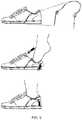
- FIG. 5shows an embodiment similar to the embodiment of FIGS. 1-4 and 6-8 and illustrates steps in using the embodiment
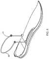
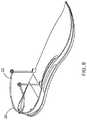
- FIGS. 6-8show various cutaway views of another embodiment of a shoe
- FIGS. 9-11show various cutaway views of another embodiment of a shoe
- FIGS. 12-13show various cutaway views of another embodiment of a shoe
- FIGS. 14-17show various cutaway views of another embodiment of a shoe
- FIGS. 18-21show various cutaway views of another embodiment of a shoe
- FIGS. 22-24show various partial-cutaway views of another embodiment of a shoe
- FIGS. 25-26show various partial-cutaway views of another embodiment of a shoe
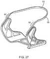
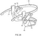
- FIGS. 27-28show perspective views of shoe components for providing rapid entry into a shoe
- FIGS. 29-33show side plan views of various shoe components for providing rapid entry into a shoe
- FIGS. 34-37show side plan views of various systems for providing rapid entry into a shoe, each system being illustrated in two operating positions;
- FIG. 38shows various plan views of a system for providing rapid entry into a shoe
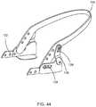
- FIGS. 39-44show perspective views of various shoe components for providing rapid entry into a shoe
- FIG. 45shows a view of a component for providing rapid entry into a shoe as well as views of various elements making up the component
- FIG. 46shows a view of a magnetic system for providing rapid entry into a shoe
- FIG. 47shows a perspective view of a rapid-entry shoe along with an exploded view of a portion of a rapid-entry component incorporated into the shoe and a cross-sectional view of the portion of the rapid-entry component;
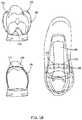
- FIGS. 48-51show views of various types of a rapid entry component and how such components can be incorporated into a rapid-entry shoe
- FIG. 52shows a rear portion of a rapid-entry shoe, illustrating a different type of rapid-entry component
- FIG. 53shows a rear portion of a rapid-entry shoe, illustrating a different type of rapid-entry component
- FIG. 54shows a rear portion of a rapid-entry shoe, illustrating a different type of rapid-entry component
- FIG. 55shows views of an embodiment of a rapid-entry shoe.
- Embodiments of the inventionprovide a rapid-entry shoe that allows the shoe to be rapidly and easily entered and readied for wearing by the user.
- Embodiments of the inventionencompass a wide variety of shoe types, enabling use of the invention with shoes of a wide variety of styles and functions. Such functions include many of the functions currently provided by such shoes, and some embodiments of the invention allow for rapid entry of the shoe without an accompanying loss of the shoe's other functionalities.
- the rapid entry features of the shoesutilize various movable elements that are fixedly attached to a sole portion of the shoe and allow movement of a portion of the shoe under pressure to allow rapid entry of the user's foot into the shoe.
- the moveable elementsmay include flexible elements, elements constructed to have a memory of a native position and/or elastic elements.
- the rapid-entry features of the shoesmay also ease use of the shoes and/or ease putting on and/or taking off of the shoes.
- FIGS. 1-4show various views of one embodiment of the invention, highlighting some of the functionality provided by embodiments of the invention.
- much of the foot-surrounding upper structure of the shoehas been omitted for clarity in illustration and understanding of the embodiments of the invention, which is also the case with many of the other Figures discussed below.
- features of the lower sole of the shoes illustrated in the Figuressuch as various patterns of tread, heel structure, and the like have also been omitted.
- the structures illustrated in the Figurescan be used in a wide variety of shoes and configurations, including sandals, closed shoes, shoes with varying heights of heels, sports shoes of many types, dress shoes, and the like. Therefore, the Figures are intended to be merely illustrative of features of some embodiments of the invention, and are not intended to be limiting of the scope of the invention as claimed.
- Some embodiments illustrated in the Figuresutilize a common underlying structure, which will be discussed herein.
- the use of the common structureillustrates several features of the invention and illustrates that a common structure may be utilized to provide a platform for a wide variety of rapid-entry shoe styles and functionalities of the type discussed herein.
- aspects of the common structure discussed hereinremain unused and/or are not needed to provide the functionality discussed with respect to particular embodiments. As such, it should be understood that in such embodiments the unused portion of the common structure could be omitted without adversely affecting the functionality of the remaining structure.
- structures other than those specifically illustratedmay be used in place of the specifically-illustrated structures to provide similar functions.
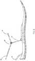
- a sole support 10is illustrated.
- the sole support 10serves to support a sole portion of a user's foot when the user is wearing the shoe.
- the sole support 10includes a ball portion 12 and a heel portion 14 .
- the sole support 10may be formed of substantially one material, or it may be manufactured or formed from multiple layers that may include multiple materials.
- the sole support 10may include or be formed from materials that serve to provide support and cushioning to the user's foot, as is known in the art.
- connection pointsserve to provide a variety of connection points for various rapid-entry structures. Some of the connection points are visible in FIG. 1 , while others are more clearly visible and illustrated in other Figures.
- the connection pointsmay be manufactured or formed from materials designed to provide sufficient strength to the rapid-entry structures discussed herein, and are generally dispersed around a periphery of the sole support 10 so as to maximize comfort of the wearer and to avoid interfering with the cushioning and support functions of the sole support 10 .
- the connection pointsmay include structures contiguously extending into an inner layer of the sole support 10 , so as to increase the strength of the connection points.
- connection pointsmay include one or more rear connection points 16 (illustrated as two closely-spaced rear connection points 16 in FIG. 1 ), one or more rear lateral connection points 18 (illustrated as one rear lateral connection point 18 on each side of the heel portion 14 in FIG. 1 ), and one or more front connection points 20 (illustrated as two closely-spaced front connection points 20 in FIG. 1 ).
- connection pointsare used in varying ways in the certain different embodiments of the invention, as will be discussed below.
- the rear lateral connection points 18are optionally utilized, along with one of the front connection points 20 on each side of the shoe.
- the front connection points 20support a paddle loop 22 on a pair of supporting stalks 24 .
- the paddle loop 22includes a rear portion 26 and a front portion 28 . In some embodiments, the front portion 28 may be omitted.
- the rear lateral connection points 18 in the illustrated embodimentsupport an optional rear support member 30 .
- the rear support member 30provides additional support to certain styles of shoe when present. When the shoe is finished, one of several scenarios may exist. In a first example, a flexible to semi-flexible material is disposed between the rear portion 26 of the paddle loop 22 and the lower back of the shoe. In a second example, a flexible to semi-flexible material is disposed between the rear portion 26 of the paddle loop 22 and the rear support member 30 . In a third example (such as a sandal-style shoe), a gap is provided in the finished shoe between the rear portion 26 of the paddle loop 22 and either the lower back of the shoe or the rear support member.
- the paddle loop 22provides for rapid entry into the shoe.
- the paddle loop 22In its resting or closed position, the paddle loop 22 naturally assumes the position shown in FIGS. 1 and 2 , such as due to spring-type forces built into the paddle loop 22 and/or due to memory of the material from which the paddle loop 22 is constructed.
- the userpushes down on the rear portion 26 of the paddle loop 22 with his or her foot, which causes the paddle loop 22 to be displaced into the position shown in FIGS. 3 and 4 .
- the usertypically does not push down on the rear portion 26 of the paddle loop 22 directly, but instead pushes down on a rear portion of the shoe structure encompassing the paddle loop 22 .
- This movement of the paddle loop 22is facilitated by the flexible to semi-flexible material or by the gap in the shoe below the rear portion 26 , as discussed above. As best seen in FIGS. 3 and 4 , the rear portion 26 of the paddle loop 22 passes in front of the rear support member 30 , allowing maximum movement of the paddle loop 22 even when the rear support member 30 is present.
- the downward motion of the rear portion 26 of the paddle loop 22causes a corresponding upward movement of the front portion 28 of the paddle loop 22 in the embodiment of FIGS. 1-4 .
- the front portion 28may remain essentially motionless for any of a variety of reasons, including a separation included between the front portion 28 and the rear portion 26 , or due to constraints on the front portion 28 in the other structures of the shoe. Regardless of the motion or lack thereof of the front portion 28 , the net effect of the movement of the paddle loop 22 causes the shoe to open substantially, thereby facilitating rapid entry of the user's foot into the shoe. Entry may be accomplished in a single motion, with the user essentially simultaneously pushing down on the rear portion 26 and sliding his or her foot into the shoe.
- FIG. 5shows the steps in this process for a completed shoe incorporating features similar to those discussed above and illustrated in more detail in FIGS. 6-8 .
- an external objectis used to push down on the rear portion 26 so the user can remove his or her foot.
- the external objectmay be any object, including the user's hand, the user's other foot, or some other object. It should be appreciated that the rapid-entry features of these embodiments facilitate putting on and taking off shoes without needing to bend over to adjust the shoes.
- embodiments of the inventionmay provide for rapid entry (and also exit) of the shoe and may further provide improvements of ease of use for some users, especially those less able to bend over when putting shoes on or off.
- embodiments of the inventionmay be used with shoes having certain adjustment features such as laces or other fasteners permitting the user to adjust the tightness of the shoes.
- a usermight adjust a shoe incorporating features of embodiments of the present invention to a desired tightness using laces or other tightening mechanisms such as straps, hook-and-loop fasteners, hooks, snaps, buckles, or any other tightening mechanisms known in the art.
- laces or other tightening mechanismssuch as straps, hook-and-loop fasteners, hooks, snaps, buckles, or any other tightening mechanisms known in the art.
- the usermay elect to utilize the rapid-entry features of embodiments of the present invention to thereafter enter and/or exit the shoe without affecting the tightness of the fit earlier selected.
- a shoe incorporating features of embodiments of the present inventionmay be kept significantly tighter in use than similar shoes without features of embodiments of the invention, while still allowing the shoe to be readily slipped on and off.
- FIGS. 9-11 and FIGS. 24-29illustrate two embodiments that utilize only the rear connection points 16 and the rear lateral connection points 18 .
- the front connection points 20are unused.
- the front connection points 20may be used by other structures in the shoe not specifically illustrated in these Figures.
- a rear flexible loop 32is attached to the rear lateral connection points and is supported by a pair of rear stays 34 that are connected to the rear connection points 16 .
- the rear flexible loop 32includes an upper spinning portion 36 that is disposed between the rear stays 34 .
- the rear flexible loop 32and in particular the upper spinning portion 36 , is at least somewhat flexible, whereby the upper spinning portion 36 deforms when a force is applied to it.
- the upper spinning portion 36may be surrounded by a flexible to semi-flexible material that allows the upper spinning portion 36 to move freely as the shoe is put on and taken off.
- the upper spinning portion 36includes a native position to which it naturally returns, such as due to memory of the material of which the rear flexible loop 32 is formed.
- the native resting (i.e. shoe closed) positionmay be further supported by the rear stays 34 . This native position is illustrated in FIGS. 9 and 10 .
- the user wishing to don the shoepushes forward and down on the back of the shoe, causing the upper spinning portion 36 to deform first forward and then downward to assume a shoe-entry position illustrated in FIG. 11 .
- a significant amount of roomhas been cleared at the back of the shoe, whereby the user's foot may more easily enter the shoe.
- the upper spinning portion 36returns to its original position, albeit possibly along a different path. Because the user's foot is in front of the upper spinning portion 36 , the upper spinning portion 36 may be unable to return to its original position by moving forward and upward. Instead, the upper spinning portion 36 may instead move backward and upward.
- the path of the upper spinning portion 36is illustrated with respect to FIGS. 10 and 11 .
- the curved arrowshows a rough representation of the path that may be taken by the upper spinning portion 36 as the user's foot enters the shoe.
- the curved arrow in FIG. 11shows a rough representation of the path that may be taken by the upper spinning portion 36 as it springs back to its native position after the user's foot enters the shoe.
- the upper spinning portion 36may take a spinning path to allow the user's foot to enter the shoe and to then return to its native position.
- the upper spinning portion 36need not take this path every time it is displaced.
- the upper spinning portion 36may move backward and downward initially when the shoe is removed, and may return along that same path.
- FIGS. 12-13The embodiment of FIGS. 12-13 is designed to function along such a line, generally moving along a single path as the user's foot enters the shoe and when the embodiment returns to its native position.
- the shoealso includes a rear flexible loop 32 and rear stays 34 , although such features may be placed somewhat differently and/or have different shapes from the embodiment discussed with respect to FIGS. 9-11 .
- the rear flexible loop 32includes a rear bending portion 38 instead of an upper spinning portion 36 .
- the rear bending portion 38moves largely up and down as the user's foot enters and exits the shoe, thereby facilitating rapid entry into the shoe. Because of the up-and-down movement of the rear bending portion 38 , the rear bending portion is not prone to inadvertently allowing the shoe to fall off the user's foot.
- FIG. 12shows the embodiment in the closed position, where the rear bending portion 38 is in its native upper position.
- FIG. 13shows the embodiment in the open position, where the rear bending portion 38 is in a downward, flexed position, such as might be assumed under an externally-supplied force to allow the user's foot to enter and exit.
- the rear stays 34may flex somewhat as the user's foot enters and/or exits, possibly providing additional clearance for the user's foot.
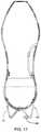
- FIGS. 14-17show an additional embodiment that utilizes primarily the rear connection points 16 and the rear lateral connection points 18 .
- This embodimentprovides a split entry into the back of the shoe, whereby the user can put his or her foot partially into the shoe, press downward on a rear portion of the shoe to cause the rear portion to split open to allow additional room for the user's foot to enter the shoe.
- FIGS. 14 and 15show the shoe in a closed position
- FIGS. 16 and 17show the shoe in a split, open position.
- a right split loop 40 and a left split loop 42are shown.
- the right split loop 40extends from a rightward of the rear lateral connection points 18 to a rightward of the rear connection points 16
- the left split loop 42extends from a leftward of the rear lateral connection points 18 to a leftward of the rear connection points 16 .
- the right split loop 40 and the left split loop 42are formed from a material and attached to the shoe in such a way as to assume a native configuration where the rear of the shoe is closed, as illustrated in FIGS. 14 and 15 .
- the illustrated embodimentincludes a rear pivoting lock 44 .
- the rear pivoting lock 44is pivotally attached to one of the right split loop 40 and the left split loop 42 and is able to reversibly latch onto the other of the right split loop 40 and the left split loop 42 , thereby locking the two together.
- the rear pivoting lock 44may be actuated through any material of the shoe to either lock or unlock, and can be actuated by a simple tap, such as using the user's other foot.
- a flexible or semi-flexible materialmay be provided at the split point at the rear of the shoe so that the two sides of the shoe do not completely split apart, but rather provide significant room for entry/exit of the user's foot.
- the rear pivoting lock 44might never be exposed during use of the rapid-entry features of the shoe.
- the rear pivoting lock 44may be left open when a roomier, loose fit is desired, and may be optionally locked when a tighter fit (such as for athletic activities) is desired.
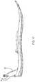
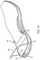
- FIGS. 18-21illustrate an alternative embodiment of a rapid-entry shoe.
- the rapid-entry feature of this shoeis a rear folding loop 46 that utilizes only the rear lateral connection points 18 .
- FIGS. 18-19show this embodiment in the native, closed position, while FIGS. 20-21 show this embodiment in an open position where the rear folding loop 46 has been pushed downward and back to allow rapid entry into the shoe.
- the function of this embodimentis similar to those described above and is self-evident from the accompanying Figures.
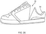
- FIGS. 22-24illustrate another alternate embodiment, this one utilizing primarily the front connection points 20 .
- the shoeincorporates a locking loop 48 connected to a flexible stay 50 on each side of the shoe.
- the flexible staysare attached to the front connection points 20 .
- the locking loop 48includes a locking portion 52 that serves to keep the shoe from opening inadvertently, as shown in FIG. 22 .
- a userapplies a downward pressure to the back of the shoe, which causes the locking portion 52 of the locking loop 48 to unlock, as shown in FIG. 25 , so the shoe can be opened. Further downward pressure causes the flexible stays to flex as shown in FIG. 24 , allowing the shoe to open.
- the reverse processmay occur, whereby the shoe returns to a closed and locked position for use.
- This movementoccurs through compression or flexing of a flexible rear portion 54 of the shoe that may serve to cause the shoe to resemble any standard shoe when not opened.
- a portion of the shoehas been cut away to facilitate understanding of the functions of the shoe. It is anticipated that the locking portion 52 and the flexible stay could remain hidden within the shoe and not normally be visible. However, in some embodiments, if the user wished to have a shoe displaying such technological features, it is anticipated that one or more functional elements might remain exposed and visible.
- FIGS. 25-26illustrate an embodiment similar to that of FIGS. 6-8 ; however, in this embodiment, the movable portion of the shoe flexes generally close to the sole of the shoe, as shown in the Figures.
- a heel portion of the shoehas been cut away to show functioning of the rapid-entry features. It should be understood that the heel may be enclosed by a flexible to semi-flexible material, by a compressible material, or by the equivalent.
- FIG. 25shows the shoe as it might normally appear (absent the cut-away heel) where it resembles a standard shoe. However, as illustrated in FIG.
- the shoewhen a downward pressure is applied to the back top 56 of the heel area, the shoe opens at a slit 58 , which may normally be covered by a piece of flexible material. This opening of the slit 58 allows the shoe to open for rapid entry of the user's foot. As the downward pressure on the back top 56 is not normal during normal use of the shoe, the shoe stays on the user's foot with little danger of inadvertent loosening of the shoe.
- the sole support 10is connected to one or more deformable elements using the various connection points.
- the deformable elemente.g. paddle loop 22 , rear flexible loop 32 , right split loop 40 and left split loop 42 , rear folding loop 46 , and flexible stay 50
- the native positionmay not be an unstressed position. In fact, the native position may already be somewhat stressed to increase the force with which the deformable element returns to the native position.
- the deformable elementmay be maintained or held in the native position by other shoe elements not necessarily shown in the Figures, such as components of the shoe upper.
- FIG. 27shows a deformable shoe component configured to provide rapid-entry features to shoes.
- the componentis configured to be inserted or manufactured into a heel portion of a shoe and may then be covered by shoe cushioning components and the like.
- the component shown in FIG. 27utilizes a deformable element 58 that has springiness or memory to return to the configuration shown in FIG. 27 . While any of a variety of materials may be used for the deformable element 58 , one exemplary material for the deformable element 58 is a flat steel spring wire similar to those used in pop-up tents and the like.
- the remaining body of the shoe componentmay include plastics, metals, composites and the like.
- the deformable element 58includes a bendable portion 60 wherein the deformable element 58 is turned so as to facilitate bending at the bendable portion 60 so as to allow a loop portion 62 to move upward and downward.
- the loop portion 62 of the deformable elementis turned so as to permit a desired bending of the loop portion 62 around the back of the user's heel/ankle while being resistant to undesired bending in other directions.
- rapid entry into a shoe containing the component shown in FIG. 27permits the user to press downward on a back portion of the shoe, insert his or her foot, and the springiness of the deformable element 62 causes the back portion to spring back up.
- the back portiondoes not tend to inadvertently release, as it is only susceptible to downward motion which is not normally encountered during use except when removal of the shoe is desire. Rapid exit may be readily achieved using the user's hand or other foot or any other object to press downward on the back portion.
- FIG. 28shows an alternative deformable shoe component.
- This componentmay be made of a variety of materials, such as plastics, metals, composites, and the like, or may incorporate several such materials.
- the illustrated embodimentincludes a heel loop 64 that is connected to a body 66 at a hinge 68 . At the hinge, a spring 70 biases the heel loop 64 upward.
- the heel loop 64includes a flexible portion 72 and a lock 74 that together serve to allow rapid entry into the shoe while minimizing undesired release of the shoe. Specifically, in the position shown in FIG. 28 , the lock 74 is engaged. When the user initially presses downward on a rear portion of the heel loop 64 , the lock 74 prevents the heel loop 64 from rotating about the hinge.
- the flexible portion 72flexes until the lock 74 is disengaged, after which the heel loop 64 is free to rotate about the hinge 68 as the user presses down further on the heel loop 64 .
- the heel loop 64is initially pressed downward, its rear portion travels substantially downward and possibly slightly forward initially, due to the positioning of the flexible portion 72 .
- the heel loop 64moves both down and backward due to positioning of the hinge 68 , with more backward motion achieved the farther down the hinge 68 is placed. This backward movement may further assist in allowing the user's foot to enter the shoe.
- the lock 74prevents unwanted backward movement (e.g. rotation about the hinge 68 ) until the lock 74 is released.
- FIGS. 29-33show plan views of various structures that may be incorporated into a rapid-entry shoe of varying types.
- the structureincludes a lock 76 similar to the lock 74 .
- the lock 76is disengaged by initial downward motion of a heel loop 78 as shown in FIG. 29 . Then, continued downward pressure causes the heel portion of the shoe to move down and back, rotating about an axis of rotation 80 as shown. Because the axis of rotation 80 is located low in the shoe, it permits significant rearward motion of the rear portion of the shoe (thus opening a slit 82 in the structure that may optionally be hidden under material) to facilitate entry into the rapid-entry shoe.
- the lock 76re-engages after the user has the shoe fully on, and prevents unwanted rearward (e.g. opening) movement of the rear portion of the shoe until the heel loop 78 is pressed downward enough to disengage the lock 76 , whereupon the shoe can be readily removed.
- FIG. 30includes features similar to those shown in FIG. 29 , but the rearward motion of the rear portion of the shoe is even more pronounced in this embodiment, as the axis of rotation 80 has been moved rearward significantly.
- the axis of rotation 80may be moved to any of a variety of intermediary locations depending on the exact desired movement of the rear portion of the shoe for rapid entry.
- FIG. 31shows another such example, with the axis of rotation moved upward and forward significantly compared with the embodiment of FIG. 30 , whereby the motion of the rear portion of the shoe after the lock 76 is disengaged is significantly more downward and less rearward.
- FIG. 32shows another embodiment, where the axis of rotation 80 is forward and up somewhat.
- the lockserves to prevent unwanted rearward (e.g. opening) of the rear portion of the shoe unless the heel loop 78 is purposely pushed downward.
- the axis of rotation 80is provided by a hinge, while in the embodiments of FIGS. 29-31 , the axis of rotation is provided by design of the component body, such as by designing in a flexible location in the body.
- one or more springsmay be used to cause the movable portion of the shoe to return to a position where the lock 76 may engage
- the flexible locationis used to provide the axis of rotation 80
- the natural desire of the material to return to its native positionmay cause the movable portion to return to a position where the lock 76 may engage.
- the axis of rotationis provided by a hinge, there may be no need to provide a slit 82 in the structure and instead a flexible portion 84 of the shoe is provided to allow the rear portion of the shoe to move for rapid entry and removal.
- FIG. 33shows an alternate embodiment illustrated as being used in a sandal-type shoe, although the illustrated embodiment could also be used in a closed-type shoe.
- the axis of rotation 80is forward and down and is associated with a spring.
- the springprovides an upward force on the heel loop 78 , causing the heel loop 78 to return upward to secure the user's foot once entry into the sandal has been achieved.
- FIGS. 34-37are examples of such embodiments. While the examples of FIGS. 34-37 are illustrated with respect to sports-type shoes, it should be understood that the illustrated principles may be applicable to all types of shoes.
- FIGS. 34-37each illustrate the embodiments in two positions, first in a position ready to receive the user's foot (an open position), and second a foot-securing position after rapid entry of the shoe has been achieved. In these embodiments, rapid entry into the shoe is provided by opening a tongue 86 of the shoe.
- FIGS. 34-37show embodiments where the system is naturally biased to an open position.
- the embodimentincludes a moveable insole 88 .
- the insole 88is biased into a position where a rear portion of the insole 88 extends upward significantly above its normal resting position when the shoe is being worn, as shown at the top of FIGS. 34-37 .
- a rear portion of the insole 88is connected to the tongue 86 by a connecting band 90 that causes the tongue 86 to move approximately in concert with the rear portion of the insole 88 .
- the connecting band 90causes the tongue 86 to close over the user's foot.
- an element of either the insole 88 or the connecting band 90engages an engaging element 92 under the insole 88 .
- the engaging element 92secures the shoe in a closed position against at least most unwanted release of the shoe.
- the engaging element 92 and any corresponding structure on the insole 88 or connecting band 90may take a variety of forms as long as they provide a reasonably-secure engagement.
- a variety of mechanismsmay be used to disengage the engaging element 92 , including an external actuator 94 that may be located on a rear surface of the shoe or on an outer side of the shoe to minimize inadvertent actuation.
- the disengagementmay be achieved by simply increasing an upward force on the tongue 86 (and thus the connecting band 90 ) beyond a level normally achieved in using the shoe except when the shoe is desired to be removed.
- FIG. 34shows an embodiment where the upward biasing on the insole 88 and tongue 86 may be achieved by way of the tongue 86 or insole 88 itself, without any additional elements.
- a spring 96is used to upwardly bias the insole 88 and thereby the tongue 86 through the connecting band 90 .
- a spring-biased barmay be used.
- no external actuator 94is present, and the user's foot is removed by exerting a force on the tongue 86 that is beyond the force normally encountered in wearing the shoe.
- the external actuator 94is present on a rear portion of the shoe.
- the external actuator 94(not shown) may be present on a side of the shoe.
- the spring-biased barmay have multiple positions of rest where one is the downward biased position. This shoe is removed in a fashion similar to that of FIG. 34 .
- FIG. 38shows an alternative manner for providing a shoe that is normally biased open.
- This shoerelies on a memory metal band 98 that terminates at each end within or near the tongue 86 of the shoe in a pair of magnets 100 .
- the memory metal band 98has a normal memory position as shown in the upper left rear view of FIG. 38 .
- the user's heelpresses down on a raised ridge 102 incorporated into the normal memory position.
- downward pressure on the raised ridge 102causes the free ends of the memory metal band 98 to be drawn together until the magnets 100 interact with each other and finish pulling the shoe closed.
- the magnets 100are “programmable magnets” otherwise known as “correlated magnets,” whereby the magnets 100 have significant strength of attraction when oriented properly to each other, but little attraction or even repulsion if adjusted only slightly in their relative orientation. This effect is achieved by having multiple polarities contained within a single magnet and corresponding opposite polarities for the other magnet such that a small lateral displacement or rotation of one magnet with respect to the other removes the various polarities from alignment and allows easy separation of the magnets. If such magnets are incorporated into the shoe shown in FIG. 38 , then the shoe may be released by applying the necessary separation motion to the magnets 100 . Otherwise, if the magnets 100 are conventional magnets, the magnets 100 may be separated and the shoe released upon applying a sufficient upward foot-removing force.
- FIGS. 39-44show perspective views of components for providing rapid entry into a shoe.
- the embodiment of FIG. 39utilizes a heel loop 104 attached at a hinged axis of rotation 80 . It may utilize one or more springs or elastic elements to cause the heel loop 104 to return to an upward position such as illustrated in FIG. 39 .
- FIG. 40also utilizes a heel loop 104 attached at a hinged axis of rotation 80 .
- This embodimentutilizes a pair of magnets 106 on each side to assist in returning the heel loop 104 to the upward position illustrated in FIG. 40 .
- any materials of the shoe surrounding the heel loop 104may also assist this or any other embodiment to return to a normal closed position.
- FIG. 41shows a view of another embodiment having a heel loop 104 .
- FIG. 42shows another embodiment having a heel loop 104 attached at a hinged axis of rotation 80 .
- This embodimenthas additional features that change the motion of the heel loop 104 as it is pressed downward.
- the heel loopis attached to forward arms 108 that have protrusions that ride in channels 110 .
- the heel loop 104is connected to the hinged axis of rotation 80 through a semi-flexible portion 112 .
- the combination of featurescauses the heel loop 104 to initially move more downward and to then transition to moving more backward, as constrained by the channels 110 . In at least some shoes, the additional backward motion may provide more room for the user's foot to enter the shoe.
- FIG. 43also has a heel loop 104 attached at a hinged axis of rotation 80 , but this version also includes a lock 114 similar to the locks previously discussed.
- the lock 114provides additional retention against unwanted rearward release of the heel loop 104 .
- the location of the axis of rotation 80is close enough to the lock 114 to make release of the lock 114 difficult or impossible simply by rotating about the axis of rotation 80 .
- a flexible portion 116 and an integral spring 118allow the heel loop to move downward without rotating about the axis of rotation until the lock 114 is released.
- This embodimentincludes a stop 120 that prevents motion of the heel loop 104 past a certain point, and reference to the previous Figures will show that some embodiments include similar features even though such features were not specifically discussed with respect to such embodiments.
- FIG. 44shows another embodiment having a heel loop 104 .
- This embodimentalso includes features not previously discussed that move the heel loop 104 rearward.
- This embodimentutilizes an anchor element 122 that is anchored to or near a sole of the shoe and has a horizontal channel 124 formed therein that contains a pin of the heel loop 104 .
- Pivotally attached to the anchor element 122 at an upper rear locationis a moveable element 126 that has a moveable element channel 128 containing another pin of the heel loop 104 .
- the pin in the moveable element channel 128moves downward as the user begins pushing on the heel loop 104 , which also moves largely downward but with some rearward motion.
- the moveable element 126will have rotated rearward somewhat, but no further downward motion of the heel loop 104 is possible without further rearward rotation of the moveable element 128 .
- the pin in the horizontal channel 124begins moving rearward, and the moveable element 126 also rotates rearward significantly more. This motion imparts additional rearward motion to the heel loop 104 , which may assist the user in entering the shoe.
- FIG. 45shows a moveable element that utilizes a flat spring 130 to allow the rear of the shoe to be collapsed for entry of a foot, with the spring causing the rear of the shoe to spring back into place.
- An upper edge of the heel portion of the shoeis provided with an upper support 132 .
- the upper support 132may be shaped to conform to the rear portion of the user's ankle and includes a spring attachment point 134 .
- Below and at or near the sole of the shoeis a lower support 136 that also has a spring attachment point 134 as shown.
- the flat spring 130which may optionally be embellished with decorative elements, is attached between the spring attachment points of the upper support 132 and the lower support 136 .
- the shoe's material between the upper support 132 and the lower support 136may be made quite flexible such that the shape of the heel portion of the shoe is largely provided by the flat spring 130 and attached upper support 132 .
- the user's footwill readily enter the shoe and the flat spring 130 will ensure that the upper support 132 springs back into place to secure the user's foot.
- FIG. 46shows features of a rapid entry shoe where the rapid entry is facilitated by components at the tongue of the shoe.
- laces of the shoewhich may essentially be standard laces, are connected to magnets 140 near the top of the tongue.
- magnets 140may be attached directly to the tongue and/or another portion of the upper of the shoe near the tongue.
- the magnets 140may be correlated magnets as discussed above, whereby separation of the magnets 140 may be readily achieved by relatively-minor rotation or translation of the magnets 140 relative to each other.
- a featuremay be added to or near to the magnets 140 to facilitate application of the translation or rotation.
- FIG. 47shows a loafer-type shoe in accordance with embodiments of the invention.
- the loafer-type shoeresembles standard loafers, with a change in that the normal thin leather strap has been replaced by a flat wire spring 142 of the type commonly used for pop-up tents.
- the flat wire spring 142may be painted, treated, or coated (e.g. with rubber) to have an appearance similar to the normal strap that has been replaced. Through much of its path, the flat wire spring 142 is disposed with a more-vertical orientation that resists vertical bending.
- FIG. 47includes a pull-out view of the flat wire spring 142 and a cross-sectional view at the location 144 .
- FIGS. 48-51show a group of embodiments of flexible tabs 150 that may be incorporated into a shoe to provide rapid entry features as discussed herein. While the flexible tabs 150 may take various shapes and forms, they have several common features. First, the flexible tabs 150 have an axis of rotation 80 . As discussed above, placement of the axis of rotation helps control how a rear portion of the shoe will open, whether largely downward or with some or significant amounts of rearward motion. Second, the flexible tabs 150 all have one or more elements that bias the flexible tabs 150 in a way that tends to close the shoe. Third, the flexible tabs 150 are connected to other portions of the shoe so as to permit the forces of the flexible tabs 150 to close the shoe.
- FIG. 48shows one embodiment of a flexible tab 150 .
- This embodimentuses a spring wire 152 in a channel 154 to bias the flexible tab 150 into the uppermost position shown in FIG. 48 .
- the lowermost position shown in FIG. 48shows how the spring wire 152 may be inserted into the channel 154 .
- the embodiment of FIG. 48also includes upper channels 156 into which an element corresponding to a heel loop can be inserted such that when such element is pressed downward, the motion is transferred to the flexible tab 150 , whereupon the spring wire 152 serves to return the flexible tab 150 to its original position along with the heel portion of the shoe.
- FIG. 49while having a significantly different shape to accommodate a different shoe structure, has largely similar features, other than that the spring wire 152 is biased into a bent position.
- the upper channels 156have been omitted in favor of simply extending the flexible tab 150 around the rear of the shoe similar in fashion to the various heel loops discussed previously.
- the embodiment of FIG. 51is largely similar, except that magnets 158 have been added to provide additional biasing to keep the flexible tab 150 in a position of a closed shoe.
- FIG. 52shows still another embodiment of a feature providing rapid entry to a shoe.
- This featureis a flexible rotatable heel strap 160 .
- the flexible rotatable heel strap 160rotates in the direction shown by the arrow in FIG. 52 , allowing the foot to more easily enter, and as the foot comes to rest in the shoe, the flexible rotatable heel strap 160 finishes a 180-degree rotation such that the inner surface of the flexible rotatable heel strap 160 is now the outer surface.
- the flexible rotatable heel strap 160is flexible so that it can conform to the user's foot regardless of what surface is outward.
- FIG. 53shows another embodiment of a rapid entry feature, namely a “breakable” strap 162 .
- This “breakable” straphas an end that can selectively “break” from its normal attachment point, such as by way of separating magnets 164 incorporated into the end and the attachment point.
- magnets 164may include correlated magnets as discussed herein.
- FIG. 54shows yet another embodiment of a rapid entry feature, again relying on magnetic forces.
- This embodimentincludes a pivoting element that utilizes magnetic force to provide a snap-to-position feel to use of the feature.
- the featurerelies on a first magnet 166 embedded in the shoe under the heel of the user's foot.
- a second magnet 168is attached to a pivoting element 170 in such a way that the first magnet 166 and the second magnet 168 repel each other.
- the pivoting element 170is pivotally attached at the rear of the shoe and is able to move between the two positions illustrated in FIG. 54 .
- the magnetsare forced together against their repelling forces until the second magnet 168 passes by the first magnet 166 , at which point the pivoting element 170 “snaps” or “jumps” into an approximately vertical position (stopped in further movement by either a portion of the shoe or by the user's ankle. In this position, the pivoting element 170 serves to retain the shoe on the user.
- the pivoting element 170is pushed back and “snaps” or “jumps” back into a more-horizontal position ready to receive the user's foot again.
- FIG. 55shows another embodiment of a rapid entry shoe utilizing features similar to those discussed with respect to the embodiment illustrated in FIG. 27 .
- This embodimentutilizes a flat metal spring wire 172 (here illustrated on an outside surface of the shoe, but potentially hidden between layers of material of the shoe) to form a heel loop 174 .
- the spring wire 172normally has its flat surface approximately vertical, so as to provide stiffness against vertical bending and to allow the heel loop 174 to bend to conform to the contours of the user's heel and/or ankle. However, near a front of the spring wire 172 , the spring wire 172 is rotated or twisted to have its flat surface approximately normal to the flat surface of the portion forming the heel loop 174 .
- a thin panel 180 or wafersuch as a plastic panel, may be incorporated on sides of the heel area of the shoe.
- the panel 180controls the shoe opening while a person steps down on the back of the shoe to insert his or her foot.
- a top portion of the panelprevents an associated portion of the opening of the shoe from bending inward, as the material below the spring wire 172 naturally bends inward as the back of the shoe collapses and thus forces the panel 180 at least slightly outward. This serves to keep the opening of the shoe more open and facilitates entry of the user's foot into the shoe.
- the top edge of the shoe openingwould tend to roll inward and somewhat block the entrance for the foot into the shoe, making entry more difficult.
Landscapes
- Footwear And Its Accessory, Manufacturing Method And Apparatuses (AREA)
Abstract
Description
Claims (12)
Priority Applications (7)
| Application Number | Priority Date | Filing Date | Title |
|---|---|---|---|
| US15/693,195US10555578B2 (en) | 2009-11-12 | 2017-08-31 | Rapid-entry shoe |
| US16/582,086US11844392B2 (en) | 2009-11-12 | 2019-09-25 | Rapid-entry shoe |
| US16/808,732US10813405B2 (en) | 2009-11-12 | 2020-03-04 | Rapid-entry shoe |
| US17/211,831US20210204645A1 (en) | 2009-11-12 | 2021-03-25 | Rapid-entry shoe |
| US17/883,355US20220369758A1 (en) | 2009-11-12 | 2022-08-08 | Rapid-entry shoe |
| US17/989,156US20230081272A1 (en) | 2009-11-12 | 2022-11-17 | Rapid-entry shoe |
| US18/371,422US20240008590A1 (en) | 2009-11-12 | 2023-09-21 | Rapid-Entry Shoe |
Applications Claiming Priority (4)
| Application Number | Priority Date | Filing Date | Title |
|---|---|---|---|
| US26062109P | 2009-11-12 | 2009-11-12 | |
| PCT/US2010/056608WO2011060316A1 (en) | 2009-11-12 | 2010-11-12 | Rapid-entry shoe |
| US201213509780A | 2012-05-14 | 2012-05-14 | |
| US15/693,195US10555578B2 (en) | 2009-11-12 | 2017-08-31 | Rapid-entry shoe |
Related Parent Applications (2)
| Application Number | Title | Priority Date | Filing Date |
|---|---|---|---|
| PCT/US2010/056608ContinuationWO2011060316A1 (en) | 2009-11-12 | 2010-11-12 | Rapid-entry shoe |
| US13/509,780ContinuationUS9877542B2 (en) | 2009-11-12 | 2010-11-12 | Rapid-entry shoe |
Related Child Applications (1)
| Application Number | Title | Priority Date | Filing Date |
|---|---|---|---|
| US16/582,086ContinuationUS11844392B2 (en) | 2009-11-12 | 2019-09-25 | Rapid-entry shoe |
Publications (2)
| Publication Number | Publication Date |
|---|---|
| US20170360151A1 US20170360151A1 (en) | 2017-12-21 |
| US10555578B2true US10555578B2 (en) | 2020-02-11 |
Family
ID=43567631
Family Applications (8)
| Application Number | Title | Priority Date | Filing Date |
|---|---|---|---|
| US13/509,780Active2032-08-23US9877542B2 (en) | 2009-11-12 | 2010-11-12 | Rapid-entry shoe |
| US15/693,195ActiveUS10555578B2 (en) | 2009-11-12 | 2017-08-31 | Rapid-entry shoe |
| US16/582,086Active2031-02-13US11844392B2 (en) | 2009-11-12 | 2019-09-25 | Rapid-entry shoe |
| US16/808,732ActiveUS10813405B2 (en) | 2009-11-12 | 2020-03-04 | Rapid-entry shoe |
| US17/211,831PendingUS20210204645A1 (en) | 2009-11-12 | 2021-03-25 | Rapid-entry shoe |
| US17/883,355PendingUS20220369758A1 (en) | 2009-11-12 | 2022-08-08 | Rapid-entry shoe |
| US17/989,156PendingUS20230081272A1 (en) | 2009-11-12 | 2022-11-17 | Rapid-entry shoe |
| US18/371,422PendingUS20240008590A1 (en) | 2009-11-12 | 2023-09-21 | Rapid-Entry Shoe |
Family Applications Before (1)
| Application Number | Title | Priority Date | Filing Date |
|---|---|---|---|
| US13/509,780Active2032-08-23US9877542B2 (en) | 2009-11-12 | 2010-11-12 | Rapid-entry shoe |
Family Applications After (6)
| Application Number | Title | Priority Date | Filing Date |
|---|---|---|---|
| US16/582,086Active2031-02-13US11844392B2 (en) | 2009-11-12 | 2019-09-25 | Rapid-entry shoe |
| US16/808,732ActiveUS10813405B2 (en) | 2009-11-12 | 2020-03-04 | Rapid-entry shoe |
| US17/211,831PendingUS20210204645A1 (en) | 2009-11-12 | 2021-03-25 | Rapid-entry shoe |
| US17/883,355PendingUS20220369758A1 (en) | 2009-11-12 | 2022-08-08 | Rapid-entry shoe |
| US17/989,156PendingUS20230081272A1 (en) | 2009-11-12 | 2022-11-17 | Rapid-entry shoe |
| US18/371,422PendingUS20240008590A1 (en) | 2009-11-12 | 2023-09-21 | Rapid-Entry Shoe |
Country Status (6)
| Country | Link |
|---|---|
| US (8) | US9877542B2 (en) |
| EP (2) | EP3864990A1 (en) |
| JP (1) | JP5722908B2 (en) |
| CN (1) | CN102770039B (en) |
| CA (1) | CA2784281C (en) |
| WO (1) | WO2011060316A1 (en) |
Cited By (6)
| Publication number | Priority date | Publication date | Assignee | Title |
|---|---|---|---|---|
| WO2022108917A1 (en)* | 2020-11-20 | 2022-05-27 | Fast Ip, Llc | Rapid-entry footwear having a split back |
| US11622598B2 (en) | 2021-08-16 | 2023-04-11 | Orthofeet, Inc. | Easy-entry shoe with a spring-flexible rear |
| USD1062184S1 (en) | 2022-09-02 | 2025-02-18 | Under Armour, Inc. | Shoe |
| US12262777B2 (en) | 2019-09-09 | 2025-04-01 | Fast Ip, Llc | Rapid-entry footwear having an arm for expanding an opening |
| US12329232B2 (en) | 2019-06-10 | 2025-06-17 | Foot Scientific, Inc. | Self-opening shoe |
| US12414601B2 (en) | 2021-02-17 | 2025-09-16 | Fast Ip, Llc | Rapid-entry footwear having a transforming footbed |
Families Citing this family (68)
| Publication number | Priority date | Publication date | Assignee | Title |
|---|---|---|---|---|
| US9877542B2 (en) | 2009-11-12 | 2018-01-30 | Fast Ip, Llc | Rapid-entry shoe |
| GB2517399A (en)* | 2013-06-21 | 2015-02-25 | Muhammad Arslaan Malik | The press-on footwear |
| JP6247038B2 (en)* | 2013-07-24 | 2017-12-13 | 雅晴 高山 | footwear |
| EP2848140A1 (en)* | 2013-09-13 | 2015-03-18 | Mickael Pais | Shoe with mobile counter |
| US20150216252A1 (en)* | 2014-01-31 | 2015-08-06 | Zubits, Llc | Footwear with magnetic closures |
| JP6125452B2 (en)* | 2014-03-24 | 2017-05-10 | 芳太郎 利行 | Shoes for care recipients |
| US20150305432A1 (en)* | 2014-04-28 | 2015-10-29 | Dutch Ideas, Llc | Magnetic footwear fasteners and magnetic footwear utilizing the same |
| CN104605580B (en)* | 2015-01-21 | 2017-01-11 | 苏州市职业大学 | Magnetic shoelace buckle |
| US10842222B2 (en) | 2015-06-29 | 2020-11-24 | Zeba Designs Llc | Collapsible shoe heel |
| EP4166028A1 (en)* | 2016-04-22 | 2023-04-19 | Fast IP, LLC | Rapid-entry footwear with rebounding fit system |
| CN105876979A (en)* | 2016-06-06 | 2016-08-24 | 陈毅 | Shoe convenient to put on |
| US10743616B2 (en) | 2016-10-26 | 2020-08-18 | Nike, Inc. | Footwear heel spring device |
| EP3531855B1 (en) | 2016-10-26 | 2021-12-01 | Nike Innovate C.V. | Upper component for an article of footwear |
| CN113729356B (en) | 2016-10-26 | 2023-05-23 | 耐克创新有限合伙公司 | Hinged footwear sole structure for foot access and method of manufacture |
| KR102545969B1 (en) | 2016-10-26 | 2023-06-20 | 나이키 이노베이트 씨.브이. | Article of footwear |
| US10159304B2 (en) | 2017-02-17 | 2018-12-25 | Christian B. Farage | Footwear having pivotable heel |
| US11304479B2 (en) | 2017-02-28 | 2022-04-19 | Nike, Inc. | Footwear with laceless fastening system |
| US10758010B2 (en) | 2017-04-17 | 2020-09-01 | Nike, Inc. | Increased access footwear |
| WO2018217423A1 (en) | 2017-05-23 | 2018-11-29 | Nike Innovate C.V. | Rear access article of footwear with movable heel portion |
| EP3629808B1 (en) | 2017-05-23 | 2021-10-13 | Nike Innovate C.V. | Footwear upper with lace-engaged zipper system |
| US10159310B2 (en) | 2017-05-25 | 2018-12-25 | Nike, Inc. | Rear closing upper for an article of footwear with front zipper to rear cord connection |
| US11000091B1 (en)* | 2017-09-01 | 2021-05-11 | Kentigern Kyle | Bimodal shoe |
| WO2019199172A1 (en) | 2018-04-12 | 2019-10-17 | Klaveness Footwear As | Footwear closure system |
| US10863797B2 (en) | 2018-04-13 | 2020-12-15 | Nike, Inc. | Footwear fastening system |
| CN108783744A (en)* | 2018-04-23 | 2018-11-13 | 丁昌林 | A kind of shoes of the orthopaedics convenient for footcare |
| USD840663S1 (en) | 2018-06-14 | 2019-02-19 | Nike, Inc. | Shoe |
| USD853707S1 (en) | 2018-06-14 | 2019-07-16 | Nike, Inc. | Shoe |
| USD854303S1 (en) | 2018-06-14 | 2019-07-23 | Nike, Inc. | Shoe |
| US10653209B2 (en) | 2018-06-28 | 2020-05-19 | Fast Ip, Llc | Rapid-entry footwear having an actuator arm |
| US10455898B1 (en) | 2018-12-21 | 2019-10-29 | Nike, Inc. | Footwear article with tongue reinforcer |
| US10617174B1 (en)* | 2018-12-21 | 2020-04-14 | Nike, Inc. | Footwear article with doffing ledge |
| US10897956B2 (en)* | 2018-12-21 | 2021-01-26 | Nike, Inc. | Footwear article with asymmetric ankle collar |
| EP3902428A1 (en) | 2018-12-28 | 2021-11-03 | NIKE Innovate C.V. | Footwear with jointed sole structure for ease of access |
| WO2020139486A1 (en)* | 2018-12-28 | 2020-07-02 | Nike Innovate C.V. | Footwear element with locating pegs and method of manufacturing an article of footwear |
| US11344077B2 (en) | 2018-12-28 | 2022-05-31 | Nike, Inc. | Footwear article with collar elevator |
| US10721994B2 (en)* | 2018-12-28 | 2020-07-28 | Nike, Inc. | Heel structure with locating pegs and method of manufacturing an article of footwear |
| US11191320B2 (en) | 2018-12-28 | 2021-12-07 | Nike, Inc. | Footwear with vertically extended heel counter |
| WO2020146176A1 (en)* | 2019-01-07 | 2020-07-16 | Fast Ip, Llc | Rapid-entry footwear having an expandable opening |
| EP3849368B1 (en)* | 2019-01-07 | 2024-01-24 | Fast IP, LLC | Rapid-entry footwear having a compressible lattice structure |
| WO2020167445A1 (en) | 2019-02-13 | 2020-08-20 | Nike Innovate C.V. | Footwear heel support device |
| EP3930527B1 (en)* | 2019-02-26 | 2025-09-24 | Fast IP, LLC | Rapid-entry footwear having a heel arm and a resilient member |
| US11140941B2 (en) | 2019-05-03 | 2021-10-12 | Nike, Inc. | Footwear upper with unitary support frame |
| CA3148597A1 (en)* | 2019-07-29 | 2021-02-04 | Fast Ip, Llc | Rapid-entry footwear having a stabilizer and an elastic element |
| CA3149874A1 (en) | 2019-09-03 | 2021-03-11 | Fast Ip, Llc | Rapid-entry footwear having a pocket for a compressed medium |
| AU2020368600B2 (en) | 2019-10-17 | 2024-05-16 | Fast Ip, Llc | Rapid-entry footwear comprised of a unified material |
| US11707113B2 (en) | 2019-10-18 | 2023-07-25 | Nike, Inc. | Easy-access article of footwear with cord lock |
| EP4064923A1 (en) | 2019-11-25 | 2022-10-05 | NIKE Innovate C.V. | Tension-retaining system for a wearable article |
| US12324476B2 (en) | 2019-12-18 | 2025-06-10 | David Erwin | Article of footwear with hands free donning and removal |
| AU2021214376A1 (en)* | 2020-01-28 | 2022-08-18 | Fast Ip, Llc | Rapid-entry footwear having rotatable straps |
| US11497271B2 (en)* | 2020-02-05 | 2022-11-15 | Se-Ho OH | Shoes |
| RU2753795C1 (en)* | 2020-08-08 | 2021-08-23 | Константин Викторович Болдин | Apparatus for putting on and removing a footwear product, methods for putting on and removal thereof |
| CN116490092A (en) | 2020-10-13 | 2023-07-25 | 飞思特知识产权有限责任公司 | Quick-entry footwear with swivel rear section and post |
| WO2022183094A1 (en) | 2021-02-26 | 2022-09-01 | Imagia Llc | Optical metalens systems |
| WO2022204444A1 (en) | 2021-03-24 | 2022-09-29 | Fast Ip, Llc | Rapid-entry footwear having a rotating tongue |
| USD1087583S1 (en) | 2021-07-16 | 2025-08-12 | Walmart Apollo, Llc | Footwear heel |
| US11744319B2 (en)* | 2021-07-27 | 2023-09-05 | Walmart Apollo, Llc | Footwear heel insert |
| US12059052B2 (en) | 2021-09-10 | 2024-08-13 | Wolverine Outdoors, Inc. | Footwear entry system |
| WO2023049414A1 (en)* | 2021-09-23 | 2023-03-30 | Fast Ip, Llc | Rapid-entry footwear having a multi-action counter |
| CN113876070B (en)* | 2021-09-29 | 2023-07-28 | 温州市爱西爱鞋业有限公司 | Man leather shoes |
| IL317627A (en) | 2021-10-15 | 2025-02-01 | Skechers Usa Inc Ii | Footwear counter for easier entry and removal |
| US12108834B2 (en) | 2021-11-12 | 2024-10-08 | Nike, Inc. | Articles of footwear and other foot-receiving devices having dynamically adjustable heel portions |
| US11910867B2 (en) | 2022-03-28 | 2024-02-27 | Nike, Inc. | Article of footwear with heel entry device |
| WO2023230385A1 (en) | 2022-05-27 | 2023-11-30 | Nike Innovate C.V. | Article of footwear with device for ease of entry |
| CN120035394A (en) | 2022-11-28 | 2025-05-23 | 耐克创新有限合伙公司 | Footwear with an articulated sole structure for easy entry |
| USD1093852S1 (en) | 2024-01-30 | 2025-09-23 | Fast Ip, Llc | Shoe |
| USD1093866S1 (en) | 2024-07-08 | 2025-09-23 | Fast Ip, Llc | Shoe |
| USD1093867S1 (en) | 2024-07-08 | 2025-09-23 | Fast Ip, Llc | Shoe |
| USD1093868S1 (en) | 2024-07-08 | 2025-09-23 | Fast Ip, Llc | Shoe |
Citations (100)
| Publication number | Priority date | Publication date | Assignee | Title |
|---|---|---|---|---|
| US112439A (en) | 1871-03-07 | Improvement in shoes | ||
| US808948A (en) | 1904-04-18 | 1906-01-02 | Noadiah P Bowler | Overshoe. |
| US827330A (en) | 1905-01-05 | 1906-07-31 | William H Tillson | Overshoe attachment. |
| US863549A (en) | 1906-07-23 | 1907-08-13 | Henry Metz | Overshoe. |
| US881153A (en) | 1907-03-04 | 1908-03-10 | Edward P Rickert | Overshoe. |
| US921461A (en) | 1907-09-16 | 1909-05-11 | Edward P Rickert | Overshoe. |
| US923860A (en) | 1908-12-28 | 1909-06-08 | Marzell Kroell | Laced shoe. |
| US1081678A (en) | 1911-07-06 | 1913-12-16 | Meyer Langerak | Shoe. |
| US1116462A (en) | 1913-07-23 | 1914-11-10 | Johnie L Moran | Storm-rubber. |
| US1464342A (en) | 1922-02-27 | 1923-08-07 | Frederick J Rothacher | Rubber attachment |
| US1494236A (en) | 1923-05-19 | 1924-05-13 | Holly G Greathouse | Overshoe clasp |
| US1686175A (en) | 1924-08-11 | 1928-10-02 | David Y Read | Footwear retainer |
| US2069752A (en) | 1935-08-17 | 1937-02-09 | Maxwell E Sparrow | Slipper, sandal, and the like |
| US2266732A (en) | 1940-04-25 | 1941-12-23 | Babinchak Stephen | Beach sandal construction |
| US2368514A (en) | 1942-03-04 | 1945-01-30 | Baehr Julius | Sandal |
| US2450250A (en) | 1945-03-14 | 1948-09-28 | John R Napton | Hinged heel shoe |
| US2452502A (en) | 1945-04-25 | 1948-10-26 | John P Tarbox | Shoe construction |
| US2736110A (en) | 1956-02-28 | hardimon | ||
| US2763071A (en) | 1952-09-25 | 1956-09-18 | Napier Clive Hastings Kingsley | Boots, shoes and like articles of footwear |
| US2829448A (en) | 1954-11-08 | 1958-04-08 | Salvador A Minera | Slipper |
| US2920402A (en) | 1957-03-18 | 1960-01-12 | Salvador A Minera | Shoe with movable counter |
| US3000116A (en) | 1959-07-31 | 1961-09-19 | Joseph H R Ally | Sandal |
| US3146535A (en) | 1963-06-13 | 1964-09-01 | David Clayman | Overshoe |
| US4489509A (en) | 1983-09-28 | 1984-12-25 | Libit Sidney M | Overshoe |
| US4590690A (en) | 1985-08-23 | 1986-05-27 | Penobscot Shoe Company | Article of footwear and method of making same |
| US4811502A (en) | 1986-06-06 | 1989-03-14 | Salomon S.A. | Sport shoe |
| JPH01181910A (en) | 1988-01-12 | 1989-07-19 | Mitsubishi Heavy Ind Ltd | Crown control apparatus for rolling mill |
| US4924605A (en) | 1985-05-22 | 1990-05-15 | Spademan Richard George | Shoe dynamic fitting and shock absorbtion system |
| US4972613A (en) | 1989-10-10 | 1990-11-27 | Wolverine World Wide, Inc. | Rear entry athletic shoe |
| US5054216A (en) | 1990-04-19 | 1991-10-08 | Lin Kuo Yang | Kind of leisure shoes |
| US5127170A (en) | 1990-01-05 | 1992-07-07 | Robert Messina | Collapsible athletic shoe |
| US5181331A (en) | 1989-06-03 | 1993-01-26 | Puma Rudolf Dassler Sport | Shoe with flexible upper material provided with a closing device |
| US5184410A (en) | 1991-06-13 | 1993-02-09 | Hamilton Paul R | Pivoting shoe construction |
| US5282327A (en) | 1993-02-16 | 1994-02-01 | Ogle Estel E | Pivotal heel for footwear |
| US5341583A (en) | 1992-07-22 | 1994-08-30 | Tretorn Ab | Sport or leisure shoe with a central closure |
| US5351583A (en) | 1993-03-03 | 1994-10-04 | Patcore, Incorporated | Toothless ratchet, clutch, and mechanisms to eliminate backlash |
| US5371957A (en) | 1993-12-14 | 1994-12-13 | Adidas America, Inc. | Athletic shoe |
| US5467537A (en) | 1994-03-18 | 1995-11-21 | Nike, Inc. | Shoe with adjustable closure system |
| US5481814A (en) | 1994-09-22 | 1996-01-09 | Spencer; Robert A. | Snap-on hinged shoe |
| DE19534249A1 (en) | 1995-09-18 | 1997-03-20 | Siegfried Drost | Shoe with lace |
| DE19611797A1 (en) | 1996-03-26 | 1997-10-02 | Richter Monika Dr | Movable heel section for footwear |
| DE29809404U1 (en) | 1998-05-13 | 1998-08-06 | Ruloff, Daniel, 12279 Berlin | Disabled footwear |
| US5842292A (en) | 1997-03-14 | 1998-12-01 | Kathy J. Siesel | Shoe insert |
| US5997027A (en) | 1997-10-09 | 1999-12-07 | Ms Trade Handels Gmbh | Arbitrarily closable and releasable connecting binding |
| US6125555A (en) | 1998-02-04 | 2000-10-03 | Schenkel; Decio Luiz | Process for attaching a shoe upper to a sole by applying staples, and the resulting shoe |
| EP1059044A1 (en) | 1999-06-11 | 2000-12-13 | Peter Niggli | Footwear with pivotal heel |
| US6189239B1 (en) | 1997-10-31 | 2001-02-20 | D. Gasparovic | Articulated footwear having a flexure member |
| JP2001149394A (en) | 1999-11-30 | 2001-06-05 | Keiai Gishi Zairyo Hanbaisho:Kk | Pediatric orthopedic shoes |
| CN2438353Y (en) | 2000-07-28 | 2001-07-11 | 周龙交 | Variable-ratio transmission-controlled shoelaces that automatically tie and untie interactive shoes |
| US6360454B1 (en) | 1998-12-07 | 2002-03-26 | The Burton Corporation | Tongue stiffener for footwear |
| US6378230B1 (en) | 2000-11-06 | 2002-04-30 | Visual3D Ltd. | Lace-less shoe |
| US20020144434A1 (en) | 2001-04-06 | 2002-10-10 | Salomon S.A. | Walking boot having a detachable upper reinforcement, and reinforcement for such a boot |
| CN1403041A (en) | 2001-09-11 | 2003-03-19 | 江登逢 | Movable back bag |
| US6671980B1 (en) | 2002-07-16 | 2004-01-06 | Kun-Chung Liu | Easy-to-wear footwear |
| US6684533B1 (en) | 2002-11-20 | 2004-02-03 | Cheng-Wen Su | Pivotal back for a sandal style shoe |
| DE10247163A1 (en) | 2002-10-05 | 2004-04-15 | Prüf- und Forschungsinstitut Pirmasens e.V. | Shoe taken on and off without manual or other help consists of a back cap stay of flexible material, spring mounted in relation to the sole, with end parts. |
| US20050022428A1 (en) | 2003-07-31 | 2005-02-03 | Anderson William T. | Shoe fastening and closure device and method of using same |
| US20050039348A1 (en)* | 2002-10-28 | 2005-02-24 | Francis Raluy | Shoe comprising automatic closing system |
| US20050076540A1 (en) | 2003-10-14 | 2005-04-14 | Cheng-Wen Su | Pivotal counter assembly for a shoe |
| US6922917B2 (en) | 2003-07-30 | 2005-08-02 | Dashamerica, Inc. | Shoe tightening system |
| DE102004005288A1 (en) | 2004-02-03 | 2005-08-11 | Florian Meyer | Shoe e.g. sport shoe, for use during e.g. team sport, has heel part definable in folded position on top part of shoe, and recess present, in closed state of part, on both sides of shoe within range of base ankle |
| US20050198867A1 (en) | 2004-03-12 | 2005-09-15 | Frederick Labbe | Self tying shoe |
| JP2006055571A (en) | 2004-08-19 | 2006-03-02 | Ellim Corp Ltd | Apparatus for tightening top of foot in leisure sports boot fixing heel to sole |
| US7103994B2 (en) | 1998-03-26 | 2006-09-12 | Johnson Gregory G | Automated tightening shoe |
| US7178270B2 (en) | 2003-10-21 | 2007-02-20 | Nike, Inc. | Engaging element useful for securing objects, such as footwear and other foot-receiving devices |
| US20070074425A1 (en)* | 2005-10-05 | 2007-04-05 | Leong Ching T | Retractable Type Lining Foot-Wears |
| US7225563B2 (en) | 2004-08-10 | 2007-06-05 | Eddie Chen | Shoe with adjustable fitting |
| WO2007080205A1 (en) | 2006-01-13 | 2007-07-19 | Francis Raluy | Shoe including an automatic closure device on the upper thereof |
| CN201005111Y (en) | 2007-03-29 | 2008-01-16 | 李宁体育(上海)有限公司 | Easy putting-on and taking-off shoes |
| US20080086911A1 (en) | 2006-10-15 | 2008-04-17 | Frederick Labbe | Weight-activated tying shoe |
| US20080189984A1 (en) | 2004-06-10 | 2008-08-14 | Reebok International Ltd. | Convertible Sandal |
| US7439837B2 (en) | 2006-01-30 | 2008-10-21 | Nike, Inc. | Article of footwear incorporating a heel strap system |
| US20080307673A1 (en) | 2007-06-14 | 2008-12-18 | Johnson Gregory G | Automated tightening shoe |
| WO2009089572A1 (en) | 2008-01-16 | 2009-07-23 | James Neville Somerville | Heel-lock shoe |
| US7661205B2 (en) | 1998-03-26 | 2010-02-16 | Johnson Gregory G | Automated tightening shoe |
| US7685747B1 (en) | 2002-04-29 | 2010-03-30 | Hatchbacks, Inc. | Footwear architecture(s) and associated closure systems |
| US7793438B1 (en) | 2007-01-26 | 2010-09-14 | Reebok International Ltd. | Rear entry footwear |
| US7823299B1 (en) | 2007-02-07 | 2010-11-02 | Brigham John P | Interchangeable flip-flop/sandal |
| US20110146106A1 (en) | 2008-03-05 | 2011-06-23 | Steven Kaufman | Hands-free step-in closure apparatus |
| US7975403B2 (en) | 2007-10-09 | 2011-07-12 | Mercury International Trading Corporation | Footwear with pivoting tongue |
| USD648512S1 (en) | 2010-08-09 | 2011-11-15 | Davmar, Inc. | Footwear |
| US8065819B2 (en) | 2008-03-05 | 2011-11-29 | Steven Kaufman | Hands-free step-in closure apparatus |
| US8161669B2 (en) | 2007-01-11 | 2012-04-24 | X-Swiss, Inc. | Infant shoe having a pivoting heel portion |
| US8225535B2 (en) | 2010-05-10 | 2012-07-24 | Deckers Outdoor Corporation | Footwear including a foldable heel |
| US20120216429A1 (en) | 2010-10-01 | 2012-08-30 | Josefina Batanero Bastida | Sole for interchangeable cut shoe or sandal |
| US20120317839A1 (en) | 2009-11-12 | 2012-12-20 | Ogio International, Inc. | Rapid-Entry Shoe |
| US20130185959A1 (en) | 2012-01-23 | 2013-07-25 | Edward Albert Coleman | Step-In Apparatus, Counter And Shoe |
| US20130219747A1 (en) | 2010-11-04 | 2013-08-29 | Stefan Lederer | Air-permeable tongue for shoes, comprising a rigid yet flexible tongue part |
| US8769845B2 (en) | 2011-01-18 | 2014-07-08 | Shu-Hua Lin | Shoe conveniently put on and taken off |
| GB2517399A (en) | 2013-06-21 | 2015-02-25 | Muhammad Arslaan Malik | The press-on footwear |
| US20150305432A1 (en) | 2014-04-28 | 2015-10-29 | Dutch Ideas, Llc | Magnetic footwear fasteners and magnetic footwear utilizing the same |
| US20160374427A1 (en) | 2015-06-29 | 2016-12-29 | Zeba Designs Llc | Collapsible shoe heel |
| US9615624B2 (en) | 2014-11-24 | 2017-04-11 | Nike, Inc. | Article of footwear with rod support system |
| US9675132B2 (en) | 2015-08-25 | 2017-06-13 | Nike, Inc. | Shoe with collapsible heel |
| US9820527B2 (en) | 2016-04-22 | 2017-11-21 | Fast Ip, Llc | Rapid-entry footwear with rebounding fit system |
| US20180110292A1 (en) | 2016-10-26 | 2018-04-26 | Nike, Inc. | Footwear heel spring device |
| US20180110287A1 (en) | 2016-10-26 | 2018-04-26 | Nike, Inc. | Hinged footwear sole structure for foot entry and method of manufacturing |
| US20180289109A1 (en) | 2016-10-26 | 2018-10-11 | Nike, Inc. | Footwear heel spring device |
| US20180295942A1 (en) | 2017-04-17 | 2018-10-18 | Nike, Inc. | Increased Access Footwear |
| US10455898B1 (en) | 2018-12-21 | 2019-10-29 | Nike, Inc. | Footwear article with tongue reinforcer |
Family Cites Families (13)
| Publication number | Priority date | Publication date | Assignee | Title |
|---|---|---|---|---|
| US2297594A (en)* | 1941-11-19 | 1942-09-29 | Weinstat Philip | Footwear |
| US2693039A (en)* | 1953-01-26 | 1954-11-02 | Raymond R Balut | Quarter construction for slippers |
| US3192651A (en)* | 1963-12-16 | 1965-07-06 | Robert D Smith | Shoe having a rear opening |
| JPS6481910A (en) | 1987-09-24 | 1989-03-28 | Nec Corp | Spectral element |
| JPH0181910U (en)* | 1987-11-21 | 1989-06-01 | ||
| GB9719089D0 (en)* | 1997-09-10 | 1997-11-12 | Scott Edward | Apparatus for fastening open heel footwear,including swimming fins |
| US6367171B1 (en)* | 2000-02-07 | 2002-04-09 | Salomon S.A. | Shoe |
| TW435102U (en)* | 2000-09-18 | 2001-05-16 | Jiang Deng Feng | Moveable rear wrapping portion for shoes |
| US6877252B2 (en)* | 2001-04-19 | 2005-04-12 | William T. Wilkinson | Slip-on shoe |
| US20020174568A1 (en)* | 2001-04-30 | 2002-11-28 | Roger Neiley | Footwear fit system |
| DE20215535U1 (en)* | 2002-10-05 | 2002-12-19 | Prüf- und Forschungsinstitut Pirmasens e.V., 66955 Pirmasens | Without aids, without the help of hands or without either loosening or opening the fastener, the shoe can be put on and taken off |
| US20080092406A1 (en)* | 2006-10-20 | 2008-04-24 | Ludemann John F | Footwear having selectively attachable sockliner |
| US20080313929A1 (en)* | 2007-06-25 | 2008-12-25 | David Hoyt | Step-in shoe with strap |
- 2010
- 2010-11-12USUS13/509,780patent/US9877542B2/enactiveActive
- 2010-11-12JPJP2012539036Apatent/JP5722908B2/enactiveActive
- 2010-11-12WOPCT/US2010/056608patent/WO2011060316A1/enactiveApplication Filing
- 2010-11-12CACA2784281Apatent/CA2784281C/enactiveActive
- 2010-11-12CNCN201080061183.8Apatent/CN102770039B/enactiveActive
- 2010-11-12EPEP21152841.9Apatent/EP3864990A1/enactivePending
- 2010-11-12EPEP10779652.6Apatent/EP2498641B1/enactiveActive
- 2017
- 2017-08-31USUS15/693,195patent/US10555578B2/enactiveActive
- 2019
- 2019-09-25USUS16/582,086patent/US11844392B2/enactiveActive
- 2020
- 2020-03-04USUS16/808,732patent/US10813405B2/enactiveActive
- 2021
- 2021-03-25USUS17/211,831patent/US20210204645A1/enactivePending
- 2022
- 2022-08-08USUS17/883,355patent/US20220369758A1/enactivePending
- 2022-11-17USUS17/989,156patent/US20230081272A1/enactivePending
- 2023
- 2023-09-21USUS18/371,422patent/US20240008590A1/enactivePending
Patent Citations (108)
| Publication number | Priority date | Publication date | Assignee | Title |
|---|---|---|---|---|
| US112439A (en) | 1871-03-07 | Improvement in shoes | ||
| US2736110A (en) | 1956-02-28 | hardimon | ||
| US808948A (en) | 1904-04-18 | 1906-01-02 | Noadiah P Bowler | Overshoe. |
| US827330A (en) | 1905-01-05 | 1906-07-31 | William H Tillson | Overshoe attachment. |
| US863549A (en) | 1906-07-23 | 1907-08-13 | Henry Metz | Overshoe. |
| US881153A (en) | 1907-03-04 | 1908-03-10 | Edward P Rickert | Overshoe. |
| US921461A (en) | 1907-09-16 | 1909-05-11 | Edward P Rickert | Overshoe. |
| US923860A (en) | 1908-12-28 | 1909-06-08 | Marzell Kroell | Laced shoe. |
| US1081678A (en) | 1911-07-06 | 1913-12-16 | Meyer Langerak | Shoe. |
| US1116462A (en) | 1913-07-23 | 1914-11-10 | Johnie L Moran | Storm-rubber. |
| US1464342A (en) | 1922-02-27 | 1923-08-07 | Frederick J Rothacher | Rubber attachment |
| US1494236A (en) | 1923-05-19 | 1924-05-13 | Holly G Greathouse | Overshoe clasp |
| US1686175A (en) | 1924-08-11 | 1928-10-02 | David Y Read | Footwear retainer |
| US2069752A (en) | 1935-08-17 | 1937-02-09 | Maxwell E Sparrow | Slipper, sandal, and the like |
| US2266732A (en) | 1940-04-25 | 1941-12-23 | Babinchak Stephen | Beach sandal construction |
| US2368514A (en) | 1942-03-04 | 1945-01-30 | Baehr Julius | Sandal |
| US2450250A (en) | 1945-03-14 | 1948-09-28 | John R Napton | Hinged heel shoe |
| US2452502A (en) | 1945-04-25 | 1948-10-26 | John P Tarbox | Shoe construction |
| US2763071A (en) | 1952-09-25 | 1956-09-18 | Napier Clive Hastings Kingsley | Boots, shoes and like articles of footwear |
| US2829448A (en) | 1954-11-08 | 1958-04-08 | Salvador A Minera | Slipper |
| US2920402A (en) | 1957-03-18 | 1960-01-12 | Salvador A Minera | Shoe with movable counter |
| US3000116A (en) | 1959-07-31 | 1961-09-19 | Joseph H R Ally | Sandal |
| US3146535A (en) | 1963-06-13 | 1964-09-01 | David Clayman | Overshoe |
| US4489509A (en) | 1983-09-28 | 1984-12-25 | Libit Sidney M | Overshoe |
| US4924605A (en) | 1985-05-22 | 1990-05-15 | Spademan Richard George | Shoe dynamic fitting and shock absorbtion system |
| US4590690A (en) | 1985-08-23 | 1986-05-27 | Penobscot Shoe Company | Article of footwear and method of making same |
| US4811502A (en) | 1986-06-06 | 1989-03-14 | Salomon S.A. | Sport shoe |
| JPH01181910A (en) | 1988-01-12 | 1989-07-19 | Mitsubishi Heavy Ind Ltd | Crown control apparatus for rolling mill |
| US5181331A (en) | 1989-06-03 | 1993-01-26 | Puma Rudolf Dassler Sport | Shoe with flexible upper material provided with a closing device |
| US4972613A (en) | 1989-10-10 | 1990-11-27 | Wolverine World Wide, Inc. | Rear entry athletic shoe |
| US5127170A (en) | 1990-01-05 | 1992-07-07 | Robert Messina | Collapsible athletic shoe |
| US5054216A (en) | 1990-04-19 | 1991-10-08 | Lin Kuo Yang | Kind of leisure shoes |
| US5184410A (en) | 1991-06-13 | 1993-02-09 | Hamilton Paul R | Pivoting shoe construction |
| US5341583A (en) | 1992-07-22 | 1994-08-30 | Tretorn Ab | Sport or leisure shoe with a central closure |
| US5282327A (en) | 1993-02-16 | 1994-02-01 | Ogle Estel E | Pivotal heel for footwear |
| US5351583A (en) | 1993-03-03 | 1994-10-04 | Patcore, Incorporated | Toothless ratchet, clutch, and mechanisms to eliminate backlash |
| US5371957A (en) | 1993-12-14 | 1994-12-13 | Adidas America, Inc. | Athletic shoe |
| US5467537A (en) | 1994-03-18 | 1995-11-21 | Nike, Inc. | Shoe with adjustable closure system |
| US5481814A (en) | 1994-09-22 | 1996-01-09 | Spencer; Robert A. | Snap-on hinged shoe |
| DE19534249A1 (en) | 1995-09-18 | 1997-03-20 | Siegfried Drost | Shoe with lace |
| DE19611797A1 (en) | 1996-03-26 | 1997-10-02 | Richter Monika Dr | Movable heel section for footwear |
| US5842292A (en) | 1997-03-14 | 1998-12-01 | Kathy J. Siesel | Shoe insert |
| US5997027A (en) | 1997-10-09 | 1999-12-07 | Ms Trade Handels Gmbh | Arbitrarily closable and releasable connecting binding |
| US6189239B1 (en) | 1997-10-31 | 2001-02-20 | D. Gasparovic | Articulated footwear having a flexure member |
| US6125555A (en) | 1998-02-04 | 2000-10-03 | Schenkel; Decio Luiz | Process for attaching a shoe upper to a sole by applying staples, and the resulting shoe |
| US7103994B2 (en) | 1998-03-26 | 2006-09-12 | Johnson Gregory G | Automated tightening shoe |
| US7661205B2 (en) | 1998-03-26 | 2010-02-16 | Johnson Gregory G | Automated tightening shoe |
| DE29809404U1 (en) | 1998-05-13 | 1998-08-06 | Ruloff, Daniel, 12279 Berlin | Disabled footwear |
| US6360454B1 (en) | 1998-12-07 | 2002-03-26 | The Burton Corporation | Tongue stiffener for footwear |
| EP1059044A1 (en) | 1999-06-11 | 2000-12-13 | Peter Niggli | Footwear with pivotal heel |
| JP2001149394A (en) | 1999-11-30 | 2001-06-05 | Keiai Gishi Zairyo Hanbaisho:Kk | Pediatric orthopedic shoes |
| CN2438353Y (en) | 2000-07-28 | 2001-07-11 | 周龙交 | Variable-ratio transmission-controlled shoelaces that automatically tie and untie interactive shoes |
| US6378230B1 (en) | 2000-11-06 | 2002-04-30 | Visual3D Ltd. | Lace-less shoe |
| US20020144434A1 (en) | 2001-04-06 | 2002-10-10 | Salomon S.A. | Walking boot having a detachable upper reinforcement, and reinforcement for such a boot |
| CN1403041A (en) | 2001-09-11 | 2003-03-19 | 江登逢 | Movable back bag |
| US7685747B1 (en) | 2002-04-29 | 2010-03-30 | Hatchbacks, Inc. | Footwear architecture(s) and associated closure systems |
| US6671980B1 (en) | 2002-07-16 | 2004-01-06 | Kun-Chung Liu | Easy-to-wear footwear |
| DE10247163A1 (en) | 2002-10-05 | 2004-04-15 | Prüf- und Forschungsinstitut Pirmasens e.V. | Shoe taken on and off without manual or other help consists of a back cap stay of flexible material, spring mounted in relation to the sole, with end parts. |
| US20050039348A1 (en)* | 2002-10-28 | 2005-02-24 | Francis Raluy | Shoe comprising automatic closing system |
| US6684533B1 (en) | 2002-11-20 | 2004-02-03 | Cheng-Wen Su | Pivotal back for a sandal style shoe |
| US6922917B2 (en) | 2003-07-30 | 2005-08-02 | Dashamerica, Inc. | Shoe tightening system |
| US20050022428A1 (en) | 2003-07-31 | 2005-02-03 | Anderson William T. | Shoe fastening and closure device and method of using same |
| US6938361B2 (en) | 2003-10-14 | 2005-09-06 | Cheng-Wen Su | Pivotal counter assembly for a shoe |
| US20050076540A1 (en) | 2003-10-14 | 2005-04-14 | Cheng-Wen Su | Pivotal counter assembly for a shoe |
| US7178270B2 (en) | 2003-10-21 | 2007-02-20 | Nike, Inc. | Engaging element useful for securing objects, such as footwear and other foot-receiving devices |
| DE102004005288A1 (en) | 2004-02-03 | 2005-08-11 | Florian Meyer | Shoe e.g. sport shoe, for use during e.g. team sport, has heel part definable in folded position on top part of shoe, and recess present, in closed state of part, on both sides of shoe within range of base ankle |
| US20050198867A1 (en) | 2004-03-12 | 2005-09-15 | Frederick Labbe | Self tying shoe |
| US20080189984A1 (en) | 2004-06-10 | 2008-08-14 | Reebok International Ltd. | Convertible Sandal |
| US7225563B2 (en) | 2004-08-10 | 2007-06-05 | Eddie Chen | Shoe with adjustable fitting |
| JP2006055571A (en) | 2004-08-19 | 2006-03-02 | Ellim Corp Ltd | Apparatus for tightening top of foot in leisure sports boot fixing heel to sole |
| US20070074425A1 (en)* | 2005-10-05 | 2007-04-05 | Leong Ching T | Retractable Type Lining Foot-Wears |
| WO2007080205A1 (en) | 2006-01-13 | 2007-07-19 | Francis Raluy | Shoe including an automatic closure device on the upper thereof |
| US7439837B2 (en) | 2006-01-30 | 2008-10-21 | Nike, Inc. | Article of footwear incorporating a heel strap system |
| US20080086911A1 (en) | 2006-10-15 | 2008-04-17 | Frederick Labbe | Weight-activated tying shoe |
| US8087188B2 (en) | 2006-10-15 | 2012-01-03 | Frederick Labbe | Weight-activated tying shoe |
| US8161669B2 (en) | 2007-01-11 | 2012-04-24 | X-Swiss, Inc. | Infant shoe having a pivoting heel portion |
| US7793438B1 (en) | 2007-01-26 | 2010-09-14 | Reebok International Ltd. | Rear entry footwear |
| US7823299B1 (en) | 2007-02-07 | 2010-11-02 | Brigham John P | Interchangeable flip-flop/sandal |
| CN201005111Y (en) | 2007-03-29 | 2008-01-16 | 李宁体育(上海)有限公司 | Easy putting-on and taking-off shoes |
| US20080307673A1 (en) | 2007-06-14 | 2008-12-18 | Johnson Gregory G | Automated tightening shoe |
| US7975403B2 (en) | 2007-10-09 | 2011-07-12 | Mercury International Trading Corporation | Footwear with pivoting tongue |
| US20110016751A1 (en)* | 2008-01-16 | 2011-01-27 | James Neville Somerville | Heel-lock shoe |
| WO2009089572A1 (en) | 2008-01-16 | 2009-07-23 | James Neville Somerville | Heel-lock shoe |
| US8065819B2 (en) | 2008-03-05 | 2011-11-29 | Steven Kaufman | Hands-free step-in closure apparatus |
| US8499474B2 (en) | 2008-03-05 | 2013-08-06 | Steven Kaufman | Hands-free step-in closure apparatus |
| US20110146106A1 (en) | 2008-03-05 | 2011-06-23 | Steven Kaufman | Hands-free step-in closure apparatus |
| US20120317839A1 (en) | 2009-11-12 | 2012-12-20 | Ogio International, Inc. | Rapid-Entry Shoe |
| US9877542B2 (en) | 2009-11-12 | 2018-01-30 | Fast Ip, Llc | Rapid-entry shoe |
| US8225535B2 (en) | 2010-05-10 | 2012-07-24 | Deckers Outdoor Corporation | Footwear including a foldable heel |
| USD648512S1 (en) | 2010-08-09 | 2011-11-15 | Davmar, Inc. | Footwear |
| US20120216429A1 (en) | 2010-10-01 | 2012-08-30 | Josefina Batanero Bastida | Sole for interchangeable cut shoe or sandal |
| US20130219747A1 (en) | 2010-11-04 | 2013-08-29 | Stefan Lederer | Air-permeable tongue for shoes, comprising a rigid yet flexible tongue part |
| US8769845B2 (en) | 2011-01-18 | 2014-07-08 | Shu-Hua Lin | Shoe conveniently put on and taken off |
| US20130185959A1 (en) | 2012-01-23 | 2013-07-25 | Edward Albert Coleman | Step-In Apparatus, Counter And Shoe |
| GB2517399A (en) | 2013-06-21 | 2015-02-25 | Muhammad Arslaan Malik | The press-on footwear |
| US20150305432A1 (en) | 2014-04-28 | 2015-10-29 | Dutch Ideas, Llc | Magnetic footwear fasteners and magnetic footwear utilizing the same |
| US9615624B2 (en) | 2014-11-24 | 2017-04-11 | Nike, Inc. | Article of footwear with rod support system |
| WO2017004135A2 (en) | 2015-06-29 | 2017-01-05 | Zeba Designs Llc | Collapsible shoe heel |
| US20160374427A1 (en) | 2015-06-29 | 2016-12-29 | Zeba Designs Llc | Collapsible shoe heel |
| US9675132B2 (en) | 2015-08-25 | 2017-06-13 | Nike, Inc. | Shoe with collapsible heel |
| US9820527B2 (en) | 2016-04-22 | 2017-11-21 | Fast Ip, Llc | Rapid-entry footwear with rebounding fit system |
| US20170360143A1 (en) | 2016-04-22 | 2017-12-21 | Fast Ip, Llc | Rapid-entry footwear with rebounding fit system |
| US10306947B2 (en) | 2016-04-22 | 2019-06-04 | Fast Ip, Llc | Rapid-entry footwear with rebounding fit system |
| US20180110292A1 (en) | 2016-10-26 | 2018-04-26 | Nike, Inc. | Footwear heel spring device |
| US20180110287A1 (en) | 2016-10-26 | 2018-04-26 | Nike, Inc. | Hinged footwear sole structure for foot entry and method of manufacturing |
| US20180289109A1 (en) | 2016-10-26 | 2018-10-11 | Nike, Inc. | Footwear heel spring device |
| US20180295942A1 (en) | 2017-04-17 | 2018-10-18 | Nike, Inc. | Increased Access Footwear |
| US10455898B1 (en) | 2018-12-21 | 2019-10-29 | Nike, Inc. | Footwear article with tongue reinforcer |
Non-Patent Citations (31)
| Title |
|---|
| Advisory Action dated Mar. 30, 2017 in U.S. Appl. No. 13/509,780. |
| EP; Examination Report dated Sep. 4, 2018 from EP Application 10779652.6. |
| European Patent Office, Examination Report dated Jan. 22, 2018 from EP Application 10 779 652.6-1011. |
| Final Office Action dated Oct. 11, 2016 in U.S. Appl. No. 13/509,780. |
| Final Office Action dated Oct. 27, 2015 in U.S. Appl. No. 13/509,780. |
| International Search Report and Written Opinion dated Aug. 22, 2017 in Application No. PCT/US2017/028774. |
| International Search Report and Written Opinion dated Feb. 23, 2011 in PCT Application No. PCT/US2010/056608. |
| Notice of Allowance dated Mar. 3, 2015 in Japanese Application No. 2012-539036. |
| Office Action dated Apr. 10, 2015 in U.S. Appl. No. 13/509,780. |
| Office Action dated Apr. 13, 2016 in U.S. Appl. No. 13/509,780. |
| Office Action dated Jun. 16, 2017 in U.S. Appl. No. 15/493,582. |
| Office Action dated May 13, 2014 in Japanese Application No. 2012-539036 (English translation not available). |
| Office Action dated May 19, 2017 in U.S. Appl. No. 13/509,780. |
| Office Action dated May 23, 2014 in Chinese Application No. 201080061183.8. |
| Office Action dated Nov. 7, 2013 in Canadian Application No. 2,784,281. |
| Office Action dated Oct. 15, 2013 in Japanese Application No. 2012-539036. |
| PCT; International Preliminary Report on Patentability dated Jun. 14, 2018 in Application No. PCT/2017/028774. |
| PCT; International Search Report and Written Opinion dated Sep. 26, 2019 in Application No. PCT/US2019/39944. |
| Restriction Requirement dated Jan. 2, 2015 in U.S. Appl. No. 13/509,780. |
| Sneider, "Kizik Handsfree New York Shoe Review," https://the-gadgeteer.com/2018/06/27/kizik-handsfree-new-york-show-review/ (2018). |
| U.S. Appl. No. 62/186,148, dated Jun. 29, 2015, Zahabian. |
| USPTO; Final Office Action dated Oct. 16, 2019 in U.S. Appl. No. 15/934,740. |
| USPTO; Final Office Action dated Oct. 9, 2018 in U.S. Appl. No. 15/690,679. |
| USPTO; Final Office Action dated Oct. 9, 2018 in U.S. Appl. No. 15/934,740. |
| USPTO; Non-Final Office Action dated Mar. 6, 2019 in U.S. Appl. No. 15/690,679. |
| USPTO; Non-Final Office Action dated Mar. 7, 2019 in U.S. Appl. No. 15/934,740. |
| USPTO; Notice of Allowance dated Apr. 10, 2019 in U.S. Appl. No. 15/690,679. |
| USPTO; Notice of Allowance dated Dec. 26, 2017 in U.S. Appl. No. 13/509,780. |
| USPTO; Notice of Allowance dated Oct. 11, 2017 in U.S. Appl. No. 15/493,582. |
| USPTO; Office Action dated May 16, 2018 in U.S. Appl. No. 15/690,679. |
| USPTO; Office Action dated May 16, 2018 in U.S. Appl. No. 15/934,740. |
Cited By (8)
| Publication number | Priority date | Publication date | Assignee | Title |
|---|---|---|---|---|
| US12329232B2 (en) | 2019-06-10 | 2025-06-17 | Foot Scientific, Inc. | Self-opening shoe |
| US12262777B2 (en) | 2019-09-09 | 2025-04-01 | Fast Ip, Llc | Rapid-entry footwear having an arm for expanding an opening |
| WO2022108917A1 (en)* | 2020-11-20 | 2022-05-27 | Fast Ip, Llc | Rapid-entry footwear having a split back |
| EP4247207A4 (en)* | 2020-11-20 | 2024-09-11 | Fast IP, LLC | SPLIT BACK QUICK ENTRY FOOTWEAR |
| US12426666B2 (en) | 2020-11-20 | 2025-09-30 | Fast Ip, Llc | Rapid-entry footwear having a split back |
| US12414601B2 (en) | 2021-02-17 | 2025-09-16 | Fast Ip, Llc | Rapid-entry footwear having a transforming footbed |
| US11622598B2 (en) | 2021-08-16 | 2023-04-11 | Orthofeet, Inc. | Easy-entry shoe with a spring-flexible rear |
| USD1062184S1 (en) | 2022-09-02 | 2025-02-18 | Under Armour, Inc. | Shoe |
Also Published As
| Publication number | Publication date |
|---|---|
| JP2013510685A (en) | 2013-03-28 |
| US20210204645A1 (en) | 2021-07-08 |
| EP2498641B1 (en) | 2021-03-03 |
| US10813405B2 (en) | 2020-10-27 |
| US20220369758A1 (en) | 2022-11-24 |
| US20240008590A1 (en) | 2024-01-11 |
| US20200214392A1 (en) | 2020-07-09 |
| CN102770039A (en) | 2012-11-07 |
| CN102770039B (en) | 2015-04-01 |
| EP3864990A1 (en) | 2021-08-18 |
| WO2011060316A1 (en) | 2011-05-19 |
| US20230081272A1 (en) | 2023-03-16 |
| US20120317839A1 (en) | 2012-12-20 |
| CA2784281C (en) | 2015-02-03 |
| US9877542B2 (en) | 2018-01-30 |
| US11844392B2 (en) | 2023-12-19 |
| US20200015544A1 (en) | 2020-01-16 |
| JP5722908B2 (en) | 2015-05-27 |
| CA2784281A1 (en) | 2011-05-19 |
| US20170360151A1 (en) | 2017-12-21 |
| EP2498641A1 (en) | 2012-09-19 |
Similar Documents
| Publication | Publication Date | Title |
|---|---|---|
| US10813405B2 (en) | Rapid-entry shoe | |
| US11564442B2 (en) | Shoe device with bimodal structures for rapid entry and release | |
| US12042015B2 (en) | Increased access footwear | |
| US20210137212A1 (en) | Easy Access Articles of Footwear | |
| US12364310B2 (en) | Rapid-entry footwear having a heel arm and a resilient member | |
| US9854875B2 (en) | Easy access articles of footwear | |
| EP1677638B1 (en) | An engaging element useful for securing objects such as footwear and other foot-receiving devices | |
| US20150020416A1 (en) | Shoe | |
| JP7084623B2 (en) | Footwear closure system | |
| US12310445B2 (en) | Shoe device with dual stadium arch bimodal structure for rapid entry and release | |
| AU2024204927A1 (en) | Shoe device with dual stadium arch bimodal structure for rapid entry and release | |
| HK1262736A1 (en) | Footwear closure system | |
| WO2010024878A1 (en) | Improved means of lacing shoes |
Legal Events
| Date | Code | Title | Description |
|---|---|---|---|
| AS | Assignment | Owner name:KIZIK DESIGN, LLC, UTAH Free format text:ASSIGNMENT OF ASSIGNORS INTEREST;ASSIGNOR:OGIO INTERNATIONAL, INC.;REEL/FRAME:043467/0330 Effective date:20170111 Owner name:OGIO INTERNATIONAL, INC., UTAH Free format text:ASSIGNMENT OF ASSIGNORS INTEREST;ASSIGNOR:PRATT, MICHAEL;REEL/FRAME:043467/0315 Effective date:20160830 Owner name:FAST IP, LLC, UTAH Free format text:CHANGE OF NAME;ASSIGNOR:KIZIK DESIGN, LLC;REEL/FRAME:043743/0580 Effective date:20170609 | |
| FEPP | Fee payment procedure | Free format text:ENTITY STATUS SET TO UNDISCOUNTED (ORIGINAL EVENT CODE: BIG.); ENTITY STATUS OF PATENT OWNER: LARGE ENTITY | |
| FEPP | Fee payment procedure | Free format text:ENTITY STATUS SET TO SMALL (ORIGINAL EVENT CODE: SMAL); ENTITY STATUS OF PATENT OWNER: LARGE ENTITY | |
| STPP | Information on status: patent application and granting procedure in general | Free format text:RESPONSE TO NON-FINAL OFFICE ACTION ENTERED AND FORWARDED TO EXAMINER | |
| STPP | Information on status: patent application and granting procedure in general | Free format text:NON FINAL ACTION MAILED | |
| STPP | Information on status: patent application and granting procedure in general | Free format text:RESPONSE TO NON-FINAL OFFICE ACTION ENTERED AND FORWARDED TO EXAMINER | |
| FEPP | Fee payment procedure | Free format text:ENTITY STATUS SET TO UNDISCOUNTED (ORIGINAL EVENT CODE: BIG.); ENTITY STATUS OF PATENT OWNER: LARGE ENTITY | |
| STPP | Information on status: patent application and granting procedure in general | Free format text:PUBLICATIONS -- ISSUE FEE PAYMENT VERIFIED | |
| STCF | Information on status: patent grant | Free format text:PATENTED CASE | |
| AS | Assignment | Owner name:JPMORGAN CHASE BANK, N.A., TEXAS Free format text:SECURITY INTEREST;ASSIGNOR:FAST IP, LLC;REEL/FRAME:060020/0758 Effective date:20220510 | |
| MAFP | Maintenance fee payment | Free format text:PAYMENT OF MAINTENANCE FEE, 4TH YEAR, LARGE ENTITY (ORIGINAL EVENT CODE: M1551); ENTITY STATUS OF PATENT OWNER: LARGE ENTITY Year of fee payment:4 | |
| AS | Assignment | Owner name:FAST IP, LLC, UTAH Free format text:RELEASE BY SECURED PARTY;ASSIGNOR:JPMORGAN CHASE BANK, N.A.;REEL/FRAME:071413/0460 Effective date:20250613 Owner name:SIENA LENDING GROUP LLC, CONNECTICUT Free format text:SECURITY INTEREST;ASSIGNORS:KIZIK DESIGN, LLC;FAST IP, LLC;HANDSFREE LABS LICENSING, LLC;AND OTHERS;REEL/FRAME:071580/0540 Effective date:20250613 |