US10555440B2 - Rack level air flow baffle providing hot aisle separation from rack-inserted it components - Google Patents
Rack level air flow baffle providing hot aisle separation from rack-inserted it componentsDownload PDFInfo
- Publication number
- US10555440B2 US10555440B2US14/509,009US201414509009AUS10555440B2US 10555440 B2US10555440 B2US 10555440B2US 201414509009 AUS201414509009 AUS 201414509009AUS 10555440 B2US10555440 B2US 10555440B2
- Authority
- US
- United States
- Prior art keywords
- rack
- baffle
- section
- air flow
- afd
- Prior art date
- Legal status (The legal status is an assumption and is not a legal conclusion. Google has not performed a legal analysis and makes no representation as to the accuracy of the status listed.)
- Active, expires
Links
Images


Classifications
- H—ELECTRICITY
- H05—ELECTRIC TECHNIQUES NOT OTHERWISE PROVIDED FOR
- H05K—PRINTED CIRCUITS; CASINGS OR CONSTRUCTIONAL DETAILS OF ELECTRIC APPARATUS; MANUFACTURE OF ASSEMBLAGES OF ELECTRICAL COMPONENTS
- H05K7/00—Constructional details common to different types of electric apparatus
- H05K7/20—Modifications to facilitate cooling, ventilating, or heating
- H05K7/20709—Modifications to facilitate cooling, ventilating, or heating for server racks or cabinets; for data centers, e.g. 19-inch computer racks
- H05K7/20718—Forced ventilation of a gaseous coolant
- H05K7/20727—Forced ventilation of a gaseous coolant within server blades for removing heat from heat source
- H—ELECTRICITY
- H05—ELECTRIC TECHNIQUES NOT OTHERWISE PROVIDED FOR
- H05K—PRINTED CIRCUITS; CASINGS OR CONSTRUCTIONAL DETAILS OF ELECTRIC APPARATUS; MANUFACTURE OF ASSEMBLAGES OF ELECTRICAL COMPONENTS
- H05K7/00—Constructional details common to different types of electric apparatus
- H05K7/20—Modifications to facilitate cooling, ventilating, or heating
- H05K7/20709—Modifications to facilitate cooling, ventilating, or heating for server racks or cabinets; for data centers, e.g. 19-inch computer racks
- H05K7/20718—Forced ventilation of a gaseous coolant
- H05K7/20736—Forced ventilation of a gaseous coolant within cabinets for removing heat from server blades
Definitions
- the present disclosuregenerally relates to information technology (IT) racks and in particular to configuration and design of air flow systems in IT racks.
- ITinformation technology
- An information handling systemgenerally processes, compiles, stores, and/or communicates information or data for business, personal, or other purposes, thereby allowing users to take advantage of the value of the information.
- information handling systemsmay also vary regarding what information is handled, how the information is handled, how much information is processed, stored, or communicated, and how quickly and efficiently the information may be processed, stored, or communicated.
- the variations in information handling systemsallow for information handling systems to be general or configured for a specific user or specific use such as financial transaction processing, airline reservations, enterprise data storage, or global communications.
- information handling systemsmay include a variety of hardware and software components that may be configured to process, store, and communicate information and may include one or more computer systems, data storage systems, and networking systems.
- IHSessuch as servers
- IHSesare often inserted placed within an information technology (IT) rack which is designed to support the weight and other requirements of the various IT components inserted within the rack.
- ITinformation technology
- rack-based implementationsare that of heat, as the IT components generate a significant amount of heat during operation and therefore must be cooled to remain functional.
- the cooling required for these rack mounted systemsis conventionally provided by external fans place in or around the rack and which pull or push cooling air through the rack from a cold aisle (typically the front of the rack) to a hot aisle (typically the rear of the rack).
- a baffleis designed for use as a back panel of an IT rack and utilized to support air flow management.
- the baffleis made of a non-porous material having at least one aperture that operates as an air flow directing (AFD) section.
- the AFDincludes inward-facing flanges, which direct the exhaust air generated from cooling air flow across heat dissipating electronic components of the IHS towards a physically separated/defined hot aisle area at the back (exterior) of the IT rack.
- the baffleis attached to a rear section of the rack chassis. The baffle provides physical separation of (i) a cold aisle located towards a front section of the rack and the electronic components inserted into the rack chassis from (ii) a hot aisle located towards a rear of the rack.
- the flanges of the AFD sectionfold inward towards the back of the electronic components to create a funnel for receiving and directing a flow of exhaust air from the rack chassis.
- the flanges of the AFD sectioncan be adhered to a rear section of an interior of the chassis.
- the AFD sectionsare located at specific vertical locations along the baffle correlating to vertically-spaced locations of the rack chassis at which the hot air exhaust, generated from passing cooling air over the functioning electronic components, can be efficiently directed away from the interior chassis section of the IT rack holding the IT gear.
- the baffleis constructed from corrugated cardboard, and the AFD apertures are cutout, perforated sections that fold inward.
- FIG. 1is a block diagram illustration of an example information technology (IT) rack and functional components of an example information handling system (IHS) that can be one IT gear located within the representation of the rack, according to one or more embodiments;
- ITinformation technology
- IHSinformation handling system
- FIG. 2illustrates a modular, easily-assembled, lightweight, and structurally-rigid (MELS) information technology (IT) rack assembly and a flat-packed representation of the sub-components thereof, according to one embodiment;
- MELSmodular, easily-assembled, lightweight, and structurally-rigid
- ITinformation technology
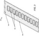
- FIG. 3illustrates a baffle that can be used in lieu of and/or as the back panel of the an IT rack, such as MELS IT rack, according to one embodiment
- FIG. 4is a first anterior view of a rack showing two attached baffles utilized for air flow directing and containment, according to one embodiment
- FIG. 5is a second anterior view of the MELS rack showing additional details of the AFD and flanges of the baffle when attached to the rack chassis, according to one embodiment
- FIG. 6illustrates the flow of cooling air from a front of the rack representing the cold aisle through the rack chassis containing the IT gear and then directed to the hot aisle at the back of the rack via the vertically-spaced AFDs of the baffle, according to one embodiment
- FIG. 7is a bird's eye view of a conventionally spaced arrangement of a row of adjacent racks, according to the prior art
- FIG. 8is an anterior view of a horizontally stacked row of IT racks configured with baffles, according to one embodiment.
- FIG. 9is a flow chart illustrating a method for controlling air flow in a horizontally stacked arrangement of racks configured with baffles, in accordance with one or more embodiments.
- a baffleis designed for use as a back panel of an IT rack and utilized to support air flow management.
- the baffleis made of a non-porous material having at least one aperture that operates as an air flow directing (AFD) section.
- the AFDincludes inward-facing flanges, which direct the exhaust air generated from cooling air flow across heat dissipating electronic components of the IHS towards a physically separated/defined hot aisle area at the back (exterior) of the IT rack.
- the baffleprovides physical separation of (i) a cold aisle located towards a front section of the rack and the interior rack chassis within which the electronic components are inserted from (ii) a hot aisle located towards a rear of the rack.
- the baffleis attached to a rear section of the rack chassis.
- the flanges of the AFD sectionfold inward towards the back of the electronic components to create a funnel for receiving and directing a flow of exhaust air from the rack chassis.
- the flanges of the AFD sectioncan be adhered to a rear section of an interior of the chassis.
- the AFD sectionsare located at specific vertical locations along the baffle correlating to vertically-spaced locations of the rack chassis at which the hot air exhaust, generated from passing cooling air over the functioning electronic components, can be efficiently directed away from the interior chassis section of the IT rack holding the IT gear.
- references within the specification to “one embodiment,” “an embodiment,” “embodiments”, or “one or more embodiments”are intended to indicate that a particular feature, structure, or characteristic described in connection with the embodiment is included in at least one embodiment of the present disclosure.
- the appearance of such phrases in various places within the specificationare not necessarily all referring to the same embodiment, nor are separate or alternative embodiments mutually exclusive of other embodiments.
- various featuresare described which may be exhibited by some embodiments and not by others.
- various requirementsare described which may be requirements for some embodiments but not other embodiments.
- FIGS. 1-6 and 8may vary.
- the illustrative components of IHS 100 and MELS IT rack 200 and baffle 300are not intended to be exhaustive, but rather are representative to highlight some of the components that are utilized to implement certain of the described embodiments.
- different configurations of an IHS and/or a rackmay be provided, containing other devices/components, which may be used in addition to or in place of the hardware depicted, and may be differently configured.
- the baffle 300can be differently configured, with different shaped openings and/or different vertical dimensions, for example.
- the depicted examplesare therefore not meant to imply architectural or other limitations with respect to the presently described embodiments and/or the general disclosures provided herein.
- FIG. 1illustrates a block diagram representation of an example information handling system (IHS) 100 , which represents one or more possible embodiments of the disclosure.
- IHSinformation handling system
- an information handling systemsuch as IHS 100
- an information handling systemmay be a handheld device, personal computer, a server, a network storage device, or any other suitable device and may vary in size, shape, performance, functionality, and price.
- the information handling systemmay include random access memory (RAM), one or more processing resources such as a central processing unit (CPU) or hardware or software control logic, ROM, and/or other types of nonvolatile memory. Additional components of the information handling system may include one or more disk drives, one or more network ports for communicating with external devices as well as various input and output (I/O) devices, such as a keyboard, a mouse, and a video display. The information handling system may also include one or more buses operable to transmit communications between the various hardware components.
- a rack structure utilized to support a rack-based information handling systemis illustrated and described. Thus, within the description, the entire rack can be described as a single information handling system, although it is appreciated that the individual IT gear inserted within one chassis of the rack can be a separate information handling system from other IT gear within the larger rack.
- IHS 160includes one or more processor(s) 102 coupled to system memory 106 via system interconnect 104 .
- System interconnect 104can be interchangeably referred to as a system bus, in one or more embodiments.
- storage 134can be a hard drive or a solid state drive.
- the one or more software and/or firmware modules within storage 134can be loaded into system memory 106 during operation of IHS 160 .
- system memory 106can include therein a plurality of modules, including Basic Input/Output System (BIOS) 110 , operating system (O/S) 108 , applications 112 and firmware (not shown).
- BIOSBasic Input/Output System
- O/Soperating system
- the various software and/or firmware moduleshave varying functionality when their corresponding program code is executed by processor(s) 102 or other processing devices within IHS 160 .
- IHS 160is located/placed within a larger structure of an IT rack 100 (generally illustrated in FIG. 1 as a surrounding exterior line). Specific structural details and method of assembling a MELS IT rack 200 are provided in FIGS. 2-6, 8 and 9 ).
- BIOS 110comprises additional functionality associated with unified extensible firmware interface (UEFI), and can be more completely referred to as BIOS/UEFI 110 in these embodiments.
- UEFIunified extensible firmware interface
- the various software and/or firmware moduleshave varying functionality when their corresponding program code is executed by processor(s) 102 or other processing devices within IHS 160 .
- IHS 160further includes one or more input/output (I/O) controllers 120 which support connection to and processing of signals from one or more connected input device(s) 122 , such as a keyboard, mouse, touch screen, or microphone. I/O controllers 120 also support connection to and forwarding of output signals to one or more connected output device(s) 124 , such as a monitor or display device or audio speaker(s).
- IHS 160includes universal serial bus (USB) 126 which is coupled to I/O controller 120 .
- USBuniversal serial bus
- one or more device interface(s) 128can be associated with IHS 160 .
- Device interface(s) 128can be utilized to enable data to be read from or stored to corresponding removable storage device(s) 130 , such as a compact disk (CD), digital video disk (DVD), flash drive, or flash memory card.
- device interface(s) 128can also provide an integration point for connecting other device(s) to IHS 160 .
- IHS 160connects to remote IHS 140 using device interface(s) 128 .
- device interface(s) 128can further include General Purpose I/O interfaces such as I 2 C, SMBus, and peripheral component interconnect (PCI) buses.
- PCIperipheral component interconnect
- IHS 160comprises a network interface device (NID) 132 .
- NID 132enables IHS 160 to communicate and/or interface with other devices, services, and components that are located external to IHS 160 . These devices, services, and components can interface with IHS 160 via an external network, such as example network 136 , using one or more communication protocols.
- IHS 160uses NID 132 to connect to remote IHS 140 via an external network 136 .
- Network 136can be a wired local area network, a wireless wide area network, wireless personal area network, wireless local area network, and the like, and the connection to and/or between network 136 and IHS 160 can be wired or wireless or a combination thereof.
- network 136is indicated as a single collective component for simplicity. However, it is appreciated that network 136 can comprise one or more direct connections to other devices as well as a more complex set of interconnections as can exist within a wide area network, such as the Internet.
- a cooling airis supplied to the rack and ultimately to the IHS 160 via one or more air movers (e.g. fans) that passes cooling air from a cold aisle over the IT gear 150 /IHS 160 within the rack (or rack chassis) 100 .
- the exhaust air that is generatedthen flows out the back of the rack 100 .
- Aspects of the present disclosureaddresses how the exhaust air is directed out of the rack chassis and kept from recirculating back to the IT gear 150 /IHS 160 within the rack 100 .
- FIG. 2illustrates an example MELS IT rack assembly, according to one embodiment.
- MELS IT rack 200is assembled using modular components 212 which can be constructed using lightweight, structural material, such as corrugated cardboard material. Included within modular components 212 is one or more baffles 220 .
- Rack 200comprises modular tray grouping and enclosure (MTGE) units 202 which respectively enclose sub-groups of IT gear receiving (ITGR) trays and cable support components to create an MTGE block 210 .
- Each MTGE block 210includes a specific number of ITGR trays in which electronic components and/or IT gear 150 ( FIG. 1 ) can be inserted/placed.
- the panelscan be sized according to a size of the modular IT rack and/or the sizes of the MTGE blocks 210 .
- Using the modularity provided by these MTGE blocks 210 as the building blocks for MELS IT rack 200allows the MELS IT rack 200 to be expanded or downsized by adding or removing one or more MTGE blocks 210 based on user/customer requirements of MELS IT rack 200 and/or vertical space limitations.
- MELS IT rack 200further comprises banding components 204 and vertical corner components 206 .
- MELS IT rack 200comprises cable support panels/components 208 .
- baffle 220when include within the flat-packed components, baffle 220 includes perforated cut-out sections 222 .
- baffle 220can be constructed from corrugated cardboard or some other lightweight but rigid material, with the AFDs being perforated cut-outs (e.g., 222 ) that can be bent inwardly into final assembly shape.
- baffles 220Once installed, in addition to provided air flow support, baffles 220 also provide some amounts of structural rigidity to the rear of the MELS IT rack.
- Baffle 220is also identified herein as baffle 300 , which is further described in FIG. 3 . Additional details of a MELS IT rack can be found in commonly assigned U.S.
- FIG. 3illustrates a baffle that can be used as a back panel of an IT rack, including the MELS IT rack 200 , according to one embodiment.
- Baffle 300is an air flow management support component having air flow directing (AFD) apertures 304 or holes with flanges that fold inwards towards the chassis of the IT rack.
- Baffle 300also includes edge 306 and notch 308 , which in one embodiment, is designed as a holding location to align and facilitate securing baffle 300 to the rack chassis.
- Baffle 300is designed to guide airflow through the IT rack using the AFD apertures. Additionally, baffle 300 is specifically designed to enable physical separation of hot and cold aisles of the physical space within which the IT rack is located.
- baffle 300is therefore referred to herein as hot aisle—cold aisle separator (HCS) baffle 300 to distinguish from other types of baffles that may be utilized for other purposes in the general IT area.
- HCS baffle 300is constructed from a light-weight material, such as corrugated cardboard, and the AFD apertures are cutout sections of the cardboard.
- the AFD aperturesare placed at specific vertical locations along the baffle to correlate to locations of the rack chassis at which the hot air exhaust from functioning IT gear can be effectively directed away from the section of the IT rack 200 holding the IT gear.
- the IT gear holding section of the MELS IT rack 200is located at the front of the rack adjacent to the cold aisle, while the exhaust air is directed to a back section of the IT rack 200 , which represents the hot aisle, on the opposite side of the HCS baffle 300 from the IT gear.
- the HCS baffle 300prevents hot air that is directed through the AFD apertures 304 from re-circulating into the cold aisle section of the IT rack 200 .
- HCS baffle 300thus assists within maintaining a lower ambient temperature of the cold aisle.
- baffle 300is affixed via adhesive edges 306 of baffle 300 to side panels 202 to provide a back panel of rack 200 .
- the AFD apertures 304are specifically sized and positioned based on a chassis design to physically interface with a chassis of the rack in order to direct air-flow and/or provide separation for hot and cold aisles.
- the AFD apertures 304 of baffle 300includes flanges or segments that fold inward at the apertures to direct or guide air flow out through the apertures. In one implementation, the inward folding segments are adhered to adjacent sections of the chassis.
- FIG. 4is a first anterior view of a rack 400 showing two attached baffles utilized for air flow directing and containment, according to one embodiment.
- the two (or more) individual baffle components 402 and 404can be provided as the back panel of the IT rack, and sized appropriately.
- FIG. 5is a second anterior view of the rack 400 showing additional details of the AFD and flanges 502 of the baffle when attached to the rack chassis 504 , according to one embodiment.
- Each baffle 402 , 404is adhered via adhesive edges of a corresponding baffle to one or more panels of IT rack 200 (such as the side panels 202 ) to collectively provide a back panel of IT rack 200 .
- a hot aisle 506is defined encompassing the entire vertical space along the back of the HCS baffle.
- FIG. 6illustrates the flow of cooling air from a front of the rack representing the cold aisle through the rack chassis containing the IT gear and then directed to the hot aisle at the back of the rack via the vertically spaced AFDs of the baffle, according to one embodiment.
- cold air 602flows from the cold aisle into a front section of the rack chassis and hot air 604 is guided out through the AFDs of the baffles towards the hot aisle at the rear section of the rack.
- baffle 300 , 402 and 404includes segments 502 that fold inward at the AFD sections to enable air flow to be guided towards a back of the baffle 300 outwards and away from the IT gear located within the chassis of the IT rack 200 .
- the inward folding segments 502adhere to adjacent sections 504 of the chassis.
- these adjacent chassis sectionsare anterior sections of MTGE blocks 210 ( FIG. 2 ).
- FIG. 7is a bird's eye view of a conventionally spaced arrangement of a row of adjacent racks, according to the prior art.
- Rack system 700comprises individual racks 702 . Also illustrated in rack system 700 are cold air flow 704 from a cold aisle 706 , hot air flow 708 at hot aisle 710 and re-circulating hot air 712 .
- hot air 708may re-circulate as re-circulating hot air 708 from the rear of the racks (hot aisle 710 ) to the front of the racks (cold aisle 706 ) causing an increase in the temperature of the IT gear and rack. This re-circulation may occur via spaces/passages between racks, through Electronics Industry Alliance (EIA) flanges and/or between servers.
- EIAElectronics Industry Alliance
- FIG. 8is an anterior view of a horizontally stacked row 800 of IT racks configured with baffles, according to one embodiment.
- Horizontally stacked row 800illustrates a row of IT racks, each of which is individually positioned to physically abut an adjacent IT rack to avoid a presence of gaps between any of the adjacent IT racks.
- Horizontally stacked row 800effectively operates as a wall that allows air flow 804 in a first direction from cold aisle 806 towards hot aisle 810 and prevents and/or minimizes re-circulation of hot air from the hot aisle 810 back towards the cold aisle 806 .
- the horizontally stacked row of IT racksprevents a reverse flow of exhaust air from the hot aisle back to the IT gear within the row of racks.
- the baffleallows the baffle to be fitted to a majority of conventional racks, as the baffle can be appropriately sized to fit on the back of these existing racks.
- the low profile of the designi.e., relatively flat configuration, small dimension, and lightweight
- the low profile of the bafflealso lends itself to utilization within a flat packed rack assembly and particularly with a modular, easily-assembled, lightweight, and structurally-rigid (MELS) IT rack assembly.
- FIG. 9presents a flowchart illustrating an example method by which a HCS baffle 300 presented within the preceding figures can be utilized to implement different aspects of the disclosure.
- method 900represents a method for utilizing a HCS baffle to provide air flow management within a single IT rack 100 and a row of racks 800 .
- the description of the methodis provided with general reference to the specific components illustrated within the preceding figures.
- FIG. 9illustrates an example method for controlling air flow in a horizontally stacked arrangement of racks configured with baffles.
- Method 900begins at the start block and proceeds to block 902 at which a user/assembler assembles one or more IT racks 200 .
- the user/assembler of IT racks 200attaches one or more HCS baffles (e.g., baffles 300 ) as a back panel (s) to a rack chassis for a first rack and/or first vertical stack of MTGE block (block 904 ).
- the user/assemblerattaches additional HCS baffles for additional and separate racks (block 906 ).
- the userhorizontally stacks the first rack and the additional racks into a row of modular IT racks such that the racks are positioned horizontally adjacent to each other to prevent re-circulation of hot air received at a hot aisle of the assembly (block 908 ).
- the processends at the end block.
- one or more of the methodsmay be embodied in a computer readable device containing computer readable code such that a series of functional processes are performed when the computer readable code is executed on a computing device.
- certain steps of the methodsare combined, performed simultaneously or in a different order, or perhaps omitted, without deviating from the scope of the disclosure.
- the method blocksare described and illustrated in a particular sequence, use of a specific sequence of functional processes represented by the blocks is not meant to imply any limitations on the disclosure. Changes may be made with regards to the sequence of processes without departing from the scope of the present disclosure. Use of a particular sequence is therefore, not to be taken in a limiting sense, and the scope of the present disclosure is defined only by the appended claims.
- These computer program instructionsmay be provided to a processor of a general purpose computer, special purpose computer, such as a service processor, or other programmable data processing apparatus to produce a machine, such that the instructions, which execute via the processor of the computer or other programmable data processing apparatus, performs the method for implementing the functions/acts specified in the flowchart and/or block diagram block or blocks.
- aspects of the present disclosuremay be implemented using any combination of software, firmware or hardware. Accordingly, aspects of the present disclosure may take the form of an entirely hardware embodiment or an embodiment combining software (including firmware, resident software, micro-code, etc.) and hardware aspects that may all generally be referred to herein as a “circuit,” “module,” or “system.”
Landscapes
- Engineering & Computer Science (AREA)
- Microelectronics & Electronic Packaging (AREA)
- Physics & Mathematics (AREA)
- Thermal Sciences (AREA)
- Computer Hardware Design (AREA)
- General Engineering & Computer Science (AREA)
- Cooling Or The Like Of Electrical Apparatus (AREA)
Abstract
Description
Claims (16)
Priority Applications (1)
| Application Number | Priority Date | Filing Date | Title |
|---|---|---|---|
| US14/509,009US10555440B2 (en) | 2014-10-07 | 2014-10-07 | Rack level air flow baffle providing hot aisle separation from rack-inserted it components |
Applications Claiming Priority (1)
| Application Number | Priority Date | Filing Date | Title |
|---|---|---|---|
| US14/509,009US10555440B2 (en) | 2014-10-07 | 2014-10-07 | Rack level air flow baffle providing hot aisle separation from rack-inserted it components |
Publications (2)
| Publication Number | Publication Date |
|---|---|
| US20160100506A1 US20160100506A1 (en) | 2016-04-07 |
| US10555440B2true US10555440B2 (en) | 2020-02-04 |
Family
ID=55633859
Family Applications (1)
| Application Number | Title | Priority Date | Filing Date |
|---|---|---|---|
| US14/509,009Active2037-06-16US10555440B2 (en) | 2014-10-07 | 2014-10-07 | Rack level air flow baffle providing hot aisle separation from rack-inserted it components |
Country Status (1)
| Country | Link |
|---|---|
| US (1) | US10555440B2 (en) |
Cited By (2)
| Publication number | Priority date | Publication date | Assignee | Title |
|---|---|---|---|---|
| US20220255173A1 (en)* | 2021-02-05 | 2022-08-11 | Caterpillar Inc. | Transportable structure for securing energy storage device racks |
| US12289867B2 (en) | 2021-05-04 | 2025-04-29 | Vertiv Corporation | Electronic equipment cabinets with configurable air plenums |
Families Citing this family (1)
| Publication number | Priority date | Publication date | Assignee | Title |
|---|---|---|---|---|
| US10390462B2 (en) | 2017-02-16 | 2019-08-20 | Dell Products, Lp | Server chassis with independent orthogonal airflow layout |
Citations (7)
| Publication number | Priority date | Publication date | Assignee | Title |
|---|---|---|---|---|
| US7857688B1 (en)* | 2006-12-11 | 2010-12-28 | Emc Corporation | Electrical cabinet having multi-channel exhaust with bleeding vents to alleviate back-pressure |
| US20120009862A1 (en) | 2010-07-06 | 2012-01-12 | Gary Meyer | Cold aisle/hot aisle containment system for computer servers in a data center |
| US20120077427A1 (en)* | 2010-09-24 | 2012-03-29 | Hon Hai Precision Industry Co., Ltd. | Container data center and heat dissipation system |
| US20120134103A1 (en)* | 2010-11-25 | 2012-05-31 | Hon Hai Precision Industry Co., Ltd. | Server cabinet for server system |
| US20130115869A1 (en)* | 2011-11-04 | 2013-05-09 | International Business Machines Corporation | Directed server rack air flow |
| US8804374B2 (en)* | 2011-10-12 | 2014-08-12 | International Business Machines Corporation | Electromagnetic interference shield |
| US20150282349A1 (en)* | 2014-03-28 | 2015-10-01 | International Business Machines Corporation | Equipment rack bracing |
- 2014
- 2014-10-07USUS14/509,009patent/US10555440B2/enactiveActive
Patent Citations (7)
| Publication number | Priority date | Publication date | Assignee | Title |
|---|---|---|---|---|
| US7857688B1 (en)* | 2006-12-11 | 2010-12-28 | Emc Corporation | Electrical cabinet having multi-channel exhaust with bleeding vents to alleviate back-pressure |
| US20120009862A1 (en) | 2010-07-06 | 2012-01-12 | Gary Meyer | Cold aisle/hot aisle containment system for computer servers in a data center |
| US20120077427A1 (en)* | 2010-09-24 | 2012-03-29 | Hon Hai Precision Industry Co., Ltd. | Container data center and heat dissipation system |
| US20120134103A1 (en)* | 2010-11-25 | 2012-05-31 | Hon Hai Precision Industry Co., Ltd. | Server cabinet for server system |
| US8804374B2 (en)* | 2011-10-12 | 2014-08-12 | International Business Machines Corporation | Electromagnetic interference shield |
| US20130115869A1 (en)* | 2011-11-04 | 2013-05-09 | International Business Machines Corporation | Directed server rack air flow |
| US20150282349A1 (en)* | 2014-03-28 | 2015-10-01 | International Business Machines Corporation | Equipment rack bracing |
Cited By (3)
| Publication number | Priority date | Publication date | Assignee | Title |
|---|---|---|---|---|
| US20220255173A1 (en)* | 2021-02-05 | 2022-08-11 | Caterpillar Inc. | Transportable structure for securing energy storage device racks |
| US12113228B2 (en)* | 2021-02-05 | 2024-10-08 | Caterpillar Inc. | Transportable structure for securing energy storage device racks |
| US12289867B2 (en) | 2021-05-04 | 2025-04-29 | Vertiv Corporation | Electronic equipment cabinets with configurable air plenums |
Also Published As
| Publication number | Publication date |
|---|---|
| US20160100506A1 (en) | 2016-04-07 |
Similar Documents
| Publication | Publication Date | Title |
|---|---|---|
| US9681586B2 (en) | Modular information technology (IT) rack and air flow system | |
| US9867318B2 (en) | Stall containment of rack in a data center | |
| US8947880B2 (en) | Hot or cold aisle computer chassis | |
| US8737067B1 (en) | Connectivity scheme and cooling scheme for a large rack system | |
| US9483089B2 (en) | System and method for integrating multiple servers into single full height bay of a server rack chassis | |
| US10856434B2 (en) | Reducing aeroacoustics caused by cooling air flow with segmented foam baffles in an information handling system | |
| US20020118514A1 (en) | Computer chassis for dual offset opposing main boards | |
| US8441788B2 (en) | Server | |
| US20100188810A1 (en) | Self-contained and modular air-cooled containerized server cooling | |
| US10555440B2 (en) | Rack level air flow baffle providing hot aisle separation from rack-inserted it components | |
| CN102289268A (en) | rack server | |
| TW201210433A (en) | Computer server cabinet | |
| US10750643B2 (en) | Airflow channeling structure for densely packed storage enclosures | |
| US10107303B2 (en) | Fluid cooled server and radiator | |
| US10492336B2 (en) | Subrack assembly for electronic equipment | |
| US10025357B2 (en) | Enclosure system for computing equipment | |
| US10925185B1 (en) | Modular data center with integrated return air plenum for external side-mounted air cooling unit | |
| US20160192532A1 (en) | Front access server | |
| US20110267770A1 (en) | Server heat dissipation system | |
| CN108227849A (en) | Covering devices for storage facilities and corresponding storage facilities | |
| US10165710B1 (en) | Cooling system for data center | |
| US20190274235A1 (en) | Housing having configurable airflow exhaust | |
| CN102736683A (en) | Container type data center | |
| TW201202898A (en) | Rack server | |
| US11665861B2 (en) | Edge datacenter nano enclosure with chimney and return air containment plenum |
Legal Events
| Date | Code | Title | Description |
|---|---|---|---|
| AS | Assignment | Owner name:DELL PRODUCTS, L.P., TEXAS Free format text:ASSIGNMENT OF ASSIGNORS INTEREST;ASSIGNORS:BAILEY, EDMOND I.;EMBLETON, STEVEN;SALAS, RENE J.;REEL/FRAME:033906/0949 Effective date:20141006 | |
| AS | Assignment | Owner name:BANK OF AMERICA, N.A., AS ADMINISTRATIVE AGENT, NORTH CAROLINA Free format text:SUPPLEMENT TO PATENT SECURITY AGREEMENT (ABL);ASSIGNORS:DELL PRODUCTS L.P.;DELL SOFTWARE INC.;FORCE10 NETWORKS, INC.;AND OTHERS;REEL/FRAME:034590/0696 Effective date:20141205 Owner name:THE BANK OF NEW YORK MELLON TRUST COMPANY, N.A., AS NOTES COLLATERAL AGENT, TEXAS Free format text:SUPPLEMENT TO PATENT SECURITY AGREEMENT (NOTES);ASSIGNORS:DELL PRODUCTS L.P.;DELL SOFTWARE INC.;FORCE10 NETWORKS, INC.;AND OTHERS;REEL/FRAME:034590/0731 Effective date:20141205 Owner name:BANK OF AMERICA, N.A., AS COLLATERAL AGENT, NORTH CAROLINA Free format text:SUPPLEMENT TO PATENT SECURITY AGREEMENT (TERM LOAN);ASSIGNORS:DELL PRODUCTS L.P.;DELL SOFTWARE INC.;FORCE10 NETWORKS, INC.;AND OTHERS;REEL/FRAME:034591/0391 Effective date:20141205 Owner name:BANK OF AMERICA, N.A., AS COLLATERAL AGENT, NORTH Free format text:SUPPLEMENT TO PATENT SECURITY AGREEMENT (TERM LOAN);ASSIGNORS:DELL PRODUCTS L.P.;DELL SOFTWARE INC.;FORCE10 NETWORKS, INC.;AND OTHERS;REEL/FRAME:034591/0391 Effective date:20141205 Owner name:BANK OF AMERICA, N.A., AS ADMINISTRATIVE AGENT, NO Free format text:SUPPLEMENT TO PATENT SECURITY AGREEMENT (ABL);ASSIGNORS:DELL PRODUCTS L.P.;DELL SOFTWARE INC.;FORCE10 NETWORKS, INC.;AND OTHERS;REEL/FRAME:034590/0696 Effective date:20141205 Owner name:THE BANK OF NEW YORK MELLON TRUST COMPANY, N.A., A Free format text:SUPPLEMENT TO PATENT SECURITY AGREEMENT (NOTES);ASSIGNORS:DELL PRODUCTS L.P.;DELL SOFTWARE INC.;FORCE10 NETWORKS, INC.;AND OTHERS;REEL/FRAME:034590/0731 Effective date:20141205 | |
| AS | Assignment | Owner name:DELL PRODUCTS L.P., TEXAS Free format text:RELEASE OF REEL 034590 FRAME 0696 (ABL);ASSIGNOR:BANK OF AMERICA, N.A., AS ADMINISTRATIVE AGENT;REEL/FRAME:040016/0964 Effective date:20160907 | |
| AS | Assignment | Owner name:DELL PRODUCTS L.P., TEXAS Free format text:RELEASE OF REEL 034590 FRAME 0731 (NOTE);ASSIGNOR:BANK OF NEW YORK MELLON TRUST COMPANY, N.A., AS COLLATERAL AGENT;REEL/FRAME:040027/0070 Effective date:20160907 Owner name:DELL PRODUCTS L.P., TEXAS Free format text:RELEASE OF REEL 034591 FRAME 0391 (TL);ASSIGNOR:BANK OF AMERICA, N.A., AS COLLATERAL AGENT;REEL/FRAME:040027/0719 Effective date:20160907 | |
| AS | Assignment | Owner name:CREDIT SUISSE AG, CAYMAN ISLANDS BRANCH, AS COLLATERAL AGENT, NORTH CAROLINA Free format text:SECURITY AGREEMENT;ASSIGNORS:ASAP SOFTWARE EXPRESS, INC.;AVENTAIL LLC;CREDANT TECHNOLOGIES, INC.;AND OTHERS;REEL/FRAME:040134/0001 Effective date:20160907 Owner name:THE BANK OF NEW YORK MELLON TRUST COMPANY, N.A., AS NOTES COLLATERAL AGENT, TEXAS Free format text:SECURITY AGREEMENT;ASSIGNORS:ASAP SOFTWARE EXPRESS, INC.;AVENTAIL LLC;CREDANT TECHNOLOGIES, INC.;AND OTHERS;REEL/FRAME:040136/0001 Effective date:20160907 Owner name:CREDIT SUISSE AG, CAYMAN ISLANDS BRANCH, AS COLLAT Free format text:SECURITY AGREEMENT;ASSIGNORS:ASAP SOFTWARE EXPRESS, INC.;AVENTAIL LLC;CREDANT TECHNOLOGIES, INC.;AND OTHERS;REEL/FRAME:040134/0001 Effective date:20160907 Owner name:THE BANK OF NEW YORK MELLON TRUST COMPANY, N.A., A Free format text:SECURITY AGREEMENT;ASSIGNORS:ASAP SOFTWARE EXPRESS, INC.;AVENTAIL LLC;CREDANT TECHNOLOGIES, INC.;AND OTHERS;REEL/FRAME:040136/0001 Effective date:20160907 | |
| STPP | Information on status: patent application and granting procedure in general | Free format text:RESPONSE TO NON-FINAL OFFICE ACTION ENTERED AND FORWARDED TO EXAMINER | |
| AS | Assignment | Owner name:THE BANK OF NEW YORK MELLON TRUST COMPANY, N.A., T Free format text:SECURITY AGREEMENT;ASSIGNORS:CREDANT TECHNOLOGIES, INC.;DELL INTERNATIONAL L.L.C.;DELL MARKETING L.P.;AND OTHERS;REEL/FRAME:049452/0223 Effective date:20190320 Owner name:THE BANK OF NEW YORK MELLON TRUST COMPANY, N.A., TEXAS Free format text:SECURITY AGREEMENT;ASSIGNORS:CREDANT TECHNOLOGIES, INC.;DELL INTERNATIONAL L.L.C.;DELL MARKETING L.P.;AND OTHERS;REEL/FRAME:049452/0223 Effective date:20190320 | |
| STPP | Information on status: patent application and granting procedure in general | Free format text:FINAL REJECTION MAILED | |
| STPP | Information on status: patent application and granting procedure in general | Free format text:RESPONSE AFTER FINAL ACTION FORWARDED TO EXAMINER | |
| STPP | Information on status: patent application and granting procedure in general | Free format text:NOTICE OF ALLOWANCE MAILED -- APPLICATION RECEIVED IN OFFICE OF PUBLICATIONS | |
| STPP | Information on status: patent application and granting procedure in general | Free format text:PUBLICATIONS -- ISSUE FEE PAYMENT VERIFIED | |
| STCF | Information on status: patent grant | Free format text:PATENTED CASE | |
| AS | Assignment | Owner name:THE BANK OF NEW YORK MELLON TRUST COMPANY, N.A., TEXAS Free format text:SECURITY AGREEMENT;ASSIGNORS:CREDANT TECHNOLOGIES INC.;DELL INTERNATIONAL L.L.C.;DELL MARKETING L.P.;AND OTHERS;REEL/FRAME:053546/0001 Effective date:20200409 | |
| AS | Assignment | Owner name:WYSE TECHNOLOGY L.L.C., CALIFORNIA Free format text:RELEASE BY SECURED PARTY;ASSIGNOR:CREDIT SUISSE AG, CAYMAN ISLANDS BRANCH;REEL/FRAME:058216/0001 Effective date:20211101 Owner name:SCALEIO LLC, MASSACHUSETTS Free format text:RELEASE BY SECURED PARTY;ASSIGNOR:CREDIT SUISSE AG, CAYMAN ISLANDS BRANCH;REEL/FRAME:058216/0001 Effective date:20211101 Owner name:MOZY, INC., WASHINGTON Free format text:RELEASE BY SECURED PARTY;ASSIGNOR:CREDIT SUISSE AG, CAYMAN ISLANDS BRANCH;REEL/FRAME:058216/0001 Effective date:20211101 Owner name:MAGINATICS LLC, CALIFORNIA Free format text:RELEASE BY SECURED PARTY;ASSIGNOR:CREDIT SUISSE AG, CAYMAN ISLANDS BRANCH;REEL/FRAME:058216/0001 Effective date:20211101 Owner name:FORCE10 NETWORKS, INC., CALIFORNIA Free format text:RELEASE BY SECURED PARTY;ASSIGNOR:CREDIT SUISSE AG, CAYMAN ISLANDS BRANCH;REEL/FRAME:058216/0001 Effective date:20211101 Owner name:EMC IP HOLDING COMPANY LLC, TEXAS Free format text:RELEASE BY SECURED PARTY;ASSIGNOR:CREDIT SUISSE AG, CAYMAN ISLANDS BRANCH;REEL/FRAME:058216/0001 Effective date:20211101 Owner name:EMC CORPORATION, MASSACHUSETTS Free format text:RELEASE BY SECURED PARTY;ASSIGNOR:CREDIT SUISSE AG, CAYMAN ISLANDS BRANCH;REEL/FRAME:058216/0001 Effective date:20211101 Owner name:DELL SYSTEMS CORPORATION, TEXAS Free format text:RELEASE BY SECURED PARTY;ASSIGNOR:CREDIT SUISSE AG, CAYMAN ISLANDS BRANCH;REEL/FRAME:058216/0001 Effective date:20211101 Owner name:DELL SOFTWARE INC., CALIFORNIA Free format text:RELEASE BY SECURED PARTY;ASSIGNOR:CREDIT SUISSE AG, CAYMAN ISLANDS BRANCH;REEL/FRAME:058216/0001 Effective date:20211101 Owner name:DELL PRODUCTS L.P., TEXAS Free format text:RELEASE BY SECURED PARTY;ASSIGNOR:CREDIT SUISSE AG, CAYMAN ISLANDS BRANCH;REEL/FRAME:058216/0001 Effective date:20211101 Owner name:DELL MARKETING L.P., TEXAS Free format text:RELEASE BY SECURED PARTY;ASSIGNOR:CREDIT SUISSE AG, CAYMAN ISLANDS BRANCH;REEL/FRAME:058216/0001 Effective date:20211101 Owner name:DELL INTERNATIONAL, L.L.C., TEXAS Free format text:RELEASE BY SECURED PARTY;ASSIGNOR:CREDIT SUISSE AG, CAYMAN ISLANDS BRANCH;REEL/FRAME:058216/0001 Effective date:20211101 Owner name:DELL USA L.P., TEXAS Free format text:RELEASE BY SECURED PARTY;ASSIGNOR:CREDIT SUISSE AG, CAYMAN ISLANDS BRANCH;REEL/FRAME:058216/0001 Effective date:20211101 Owner name:CREDANT TECHNOLOGIES, INC., TEXAS Free format text:RELEASE BY SECURED PARTY;ASSIGNOR:CREDIT SUISSE AG, CAYMAN ISLANDS BRANCH;REEL/FRAME:058216/0001 Effective date:20211101 Owner name:AVENTAIL LLC, CALIFORNIA Free format text:RELEASE BY SECURED PARTY;ASSIGNOR:CREDIT SUISSE AG, CAYMAN ISLANDS BRANCH;REEL/FRAME:058216/0001 Effective date:20211101 Owner name:ASAP SOFTWARE EXPRESS, INC., ILLINOIS Free format text:RELEASE BY SECURED PARTY;ASSIGNOR:CREDIT SUISSE AG, CAYMAN ISLANDS BRANCH;REEL/FRAME:058216/0001 Effective date:20211101 | |
| AS | Assignment | Owner name:SCALEIO LLC, MASSACHUSETTS Free format text:RELEASE OF SECURITY INTEREST IN PATENTS PREVIOUSLY RECORDED AT REEL/FRAME (040136/0001);ASSIGNOR:THE BANK OF NEW YORK MELLON TRUST COMPANY, N.A., AS NOTES COLLATERAL AGENT;REEL/FRAME:061324/0001 Effective date:20220329 Owner name:EMC IP HOLDING COMPANY LLC (ON BEHALF OF ITSELF AND AS SUCCESSOR-IN-INTEREST TO MOZY, INC.), TEXAS Free format text:RELEASE OF SECURITY INTEREST IN PATENTS PREVIOUSLY RECORDED AT REEL/FRAME (040136/0001);ASSIGNOR:THE BANK OF NEW YORK MELLON TRUST COMPANY, N.A., AS NOTES COLLATERAL AGENT;REEL/FRAME:061324/0001 Effective date:20220329 Owner name:EMC CORPORATION (ON BEHALF OF ITSELF AND AS SUCCESSOR-IN-INTEREST TO MAGINATICS LLC), MASSACHUSETTS Free format text:RELEASE OF SECURITY INTEREST IN PATENTS PREVIOUSLY RECORDED AT REEL/FRAME (040136/0001);ASSIGNOR:THE BANK OF NEW YORK MELLON TRUST COMPANY, N.A., AS NOTES COLLATERAL AGENT;REEL/FRAME:061324/0001 Effective date:20220329 Owner name:DELL MARKETING CORPORATION (SUCCESSOR-IN-INTEREST TO FORCE10 NETWORKS, INC. AND WYSE TECHNOLOGY L.L.C.), TEXAS Free format text:RELEASE OF SECURITY INTEREST IN PATENTS PREVIOUSLY RECORDED AT REEL/FRAME (040136/0001);ASSIGNOR:THE BANK OF NEW YORK MELLON TRUST COMPANY, N.A., AS NOTES COLLATERAL AGENT;REEL/FRAME:061324/0001 Effective date:20220329 Owner name:DELL PRODUCTS L.P., TEXAS Free format text:RELEASE OF SECURITY INTEREST IN PATENTS PREVIOUSLY RECORDED AT REEL/FRAME (040136/0001);ASSIGNOR:THE BANK OF NEW YORK MELLON TRUST COMPANY, N.A., AS NOTES COLLATERAL AGENT;REEL/FRAME:061324/0001 Effective date:20220329 Owner name:DELL INTERNATIONAL L.L.C., TEXAS Free format text:RELEASE OF SECURITY INTEREST IN PATENTS PREVIOUSLY RECORDED AT REEL/FRAME (040136/0001);ASSIGNOR:THE BANK OF NEW YORK MELLON TRUST COMPANY, N.A., AS NOTES COLLATERAL AGENT;REEL/FRAME:061324/0001 Effective date:20220329 Owner name:DELL USA L.P., TEXAS Free format text:RELEASE OF SECURITY INTEREST IN PATENTS PREVIOUSLY RECORDED AT REEL/FRAME (040136/0001);ASSIGNOR:THE BANK OF NEW YORK MELLON TRUST COMPANY, N.A., AS NOTES COLLATERAL AGENT;REEL/FRAME:061324/0001 Effective date:20220329 Owner name:DELL MARKETING L.P. (ON BEHALF OF ITSELF AND AS SUCCESSOR-IN-INTEREST TO CREDANT TECHNOLOGIES, INC.), TEXAS Free format text:RELEASE OF SECURITY INTEREST IN PATENTS PREVIOUSLY RECORDED AT REEL/FRAME (040136/0001);ASSIGNOR:THE BANK OF NEW YORK MELLON TRUST COMPANY, N.A., AS NOTES COLLATERAL AGENT;REEL/FRAME:061324/0001 Effective date:20220329 Owner name:DELL MARKETING CORPORATION (SUCCESSOR-IN-INTEREST TO ASAP SOFTWARE EXPRESS, INC.), TEXAS Free format text:RELEASE OF SECURITY INTEREST IN PATENTS PREVIOUSLY RECORDED AT REEL/FRAME (040136/0001);ASSIGNOR:THE BANK OF NEW YORK MELLON TRUST COMPANY, N.A., AS NOTES COLLATERAL AGENT;REEL/FRAME:061324/0001 Effective date:20220329 | |
| AS | Assignment | Owner name:SCALEIO LLC, MASSACHUSETTS Free format text:RELEASE OF SECURITY INTEREST IN PATENTS PREVIOUSLY RECORDED AT REEL/FRAME (045455/0001);ASSIGNOR:THE BANK OF NEW YORK MELLON TRUST COMPANY, N.A., AS NOTES COLLATERAL AGENT;REEL/FRAME:061753/0001 Effective date:20220329 Owner name:EMC IP HOLDING COMPANY LLC (ON BEHALF OF ITSELF AND AS SUCCESSOR-IN-INTEREST TO MOZY, INC.), TEXAS Free format text:RELEASE OF SECURITY INTEREST IN PATENTS PREVIOUSLY RECORDED AT REEL/FRAME (045455/0001);ASSIGNOR:THE BANK OF NEW YORK MELLON TRUST COMPANY, N.A., AS NOTES COLLATERAL AGENT;REEL/FRAME:061753/0001 Effective date:20220329 Owner name:EMC CORPORATION (ON BEHALF OF ITSELF AND AS SUCCESSOR-IN-INTEREST TO MAGINATICS LLC), MASSACHUSETTS Free format text:RELEASE OF SECURITY INTEREST IN PATENTS PREVIOUSLY RECORDED AT REEL/FRAME (045455/0001);ASSIGNOR:THE BANK OF NEW YORK MELLON TRUST COMPANY, N.A., AS NOTES COLLATERAL AGENT;REEL/FRAME:061753/0001 Effective date:20220329 Owner name:DELL MARKETING CORPORATION (SUCCESSOR-IN-INTEREST TO FORCE10 NETWORKS, INC. AND WYSE TECHNOLOGY L.L.C.), TEXAS Free format text:RELEASE OF SECURITY INTEREST IN PATENTS PREVIOUSLY RECORDED AT REEL/FRAME (045455/0001);ASSIGNOR:THE BANK OF NEW YORK MELLON TRUST COMPANY, N.A., AS NOTES COLLATERAL AGENT;REEL/FRAME:061753/0001 Effective date:20220329 Owner name:DELL PRODUCTS L.P., TEXAS Free format text:RELEASE OF SECURITY INTEREST IN PATENTS PREVIOUSLY RECORDED AT REEL/FRAME (045455/0001);ASSIGNOR:THE BANK OF NEW YORK MELLON TRUST COMPANY, N.A., AS NOTES COLLATERAL AGENT;REEL/FRAME:061753/0001 Effective date:20220329 Owner name:DELL INTERNATIONAL L.L.C., TEXAS Free format text:RELEASE OF SECURITY INTEREST IN PATENTS PREVIOUSLY RECORDED AT REEL/FRAME (045455/0001);ASSIGNOR:THE BANK OF NEW YORK MELLON TRUST COMPANY, N.A., AS NOTES COLLATERAL AGENT;REEL/FRAME:061753/0001 Effective date:20220329 Owner name:DELL USA L.P., TEXAS Free format text:RELEASE OF SECURITY INTEREST IN PATENTS PREVIOUSLY RECORDED AT REEL/FRAME (045455/0001);ASSIGNOR:THE BANK OF NEW YORK MELLON TRUST COMPANY, N.A., AS NOTES COLLATERAL AGENT;REEL/FRAME:061753/0001 Effective date:20220329 Owner name:DELL MARKETING L.P. (ON BEHALF OF ITSELF AND AS SUCCESSOR-IN-INTEREST TO CREDANT TECHNOLOGIES, INC.), TEXAS Free format text:RELEASE OF SECURITY INTEREST IN PATENTS PREVIOUSLY RECORDED AT REEL/FRAME (045455/0001);ASSIGNOR:THE BANK OF NEW YORK MELLON TRUST COMPANY, N.A., AS NOTES COLLATERAL AGENT;REEL/FRAME:061753/0001 Effective date:20220329 Owner name:DELL MARKETING CORPORATION (SUCCESSOR-IN-INTEREST TO ASAP SOFTWARE EXPRESS, INC.), TEXAS Free format text:RELEASE OF SECURITY INTEREST IN PATENTS PREVIOUSLY RECORDED AT REEL/FRAME (045455/0001);ASSIGNOR:THE BANK OF NEW YORK MELLON TRUST COMPANY, N.A., AS NOTES COLLATERAL AGENT;REEL/FRAME:061753/0001 Effective date:20220329 | |
| AS | Assignment | Owner name:DELL MARKETING L.P. (ON BEHALF OF ITSELF AND AS SUCCESSOR-IN-INTEREST TO CREDANT TECHNOLOGIES, INC.), TEXAS Free format text:RELEASE OF SECURITY INTEREST IN PATENTS PREVIOUSLY RECORDED AT REEL/FRAME (053546/0001);ASSIGNOR:THE BANK OF NEW YORK MELLON TRUST COMPANY, N.A., AS NOTES COLLATERAL AGENT;REEL/FRAME:071642/0001 Effective date:20220329 Owner name:DELL INTERNATIONAL L.L.C., TEXAS Free format text:RELEASE OF SECURITY INTEREST IN PATENTS PREVIOUSLY RECORDED AT REEL/FRAME (053546/0001);ASSIGNOR:THE BANK OF NEW YORK MELLON TRUST COMPANY, N.A., AS NOTES COLLATERAL AGENT;REEL/FRAME:071642/0001 Effective date:20220329 Owner name:DELL PRODUCTS L.P., TEXAS Free format text:RELEASE OF SECURITY INTEREST IN PATENTS PREVIOUSLY RECORDED AT REEL/FRAME (053546/0001);ASSIGNOR:THE BANK OF NEW YORK MELLON TRUST COMPANY, N.A., AS NOTES COLLATERAL AGENT;REEL/FRAME:071642/0001 Effective date:20220329 Owner name:DELL USA L.P., TEXAS Free format text:RELEASE OF SECURITY INTEREST IN PATENTS PREVIOUSLY RECORDED AT REEL/FRAME (053546/0001);ASSIGNOR:THE BANK OF NEW YORK MELLON TRUST COMPANY, N.A., AS NOTES COLLATERAL AGENT;REEL/FRAME:071642/0001 Effective date:20220329 Owner name:EMC CORPORATION, MASSACHUSETTS Free format text:RELEASE OF SECURITY INTEREST IN PATENTS PREVIOUSLY RECORDED AT REEL/FRAME (053546/0001);ASSIGNOR:THE BANK OF NEW YORK MELLON TRUST COMPANY, N.A., AS NOTES COLLATERAL AGENT;REEL/FRAME:071642/0001 Effective date:20220329 Owner name:DELL MARKETING CORPORATION (SUCCESSOR-IN-INTEREST TO FORCE10 NETWORKS, INC. AND WYSE TECHNOLOGY L.L.C.), TEXAS Free format text:RELEASE OF SECURITY INTEREST IN PATENTS PREVIOUSLY RECORDED AT REEL/FRAME (053546/0001);ASSIGNOR:THE BANK OF NEW YORK MELLON TRUST COMPANY, N.A., AS NOTES COLLATERAL AGENT;REEL/FRAME:071642/0001 Effective date:20220329 Owner name:EMC IP HOLDING COMPANY LLC, TEXAS Free format text:RELEASE OF SECURITY INTEREST IN PATENTS PREVIOUSLY RECORDED AT REEL/FRAME (053546/0001);ASSIGNOR:THE BANK OF NEW YORK MELLON TRUST COMPANY, N.A., AS NOTES COLLATERAL AGENT;REEL/FRAME:071642/0001 Effective date:20220329 | |
| MAFP | Maintenance fee payment | Free format text:PAYMENT OF MAINTENANCE FEE, 4TH YEAR, LARGE ENTITY (ORIGINAL EVENT CODE: M1551); ENTITY STATUS OF PATENT OWNER: LARGE ENTITY Year of fee payment:4 |