US10555305B2 - Transmission apparatus and transmission method using a plurality of divided frequency bands in a communication band - Google Patents
Transmission apparatus and transmission method using a plurality of divided frequency bands in a communication bandDownload PDFInfo
- Publication number
- US10555305B2 US10555305B2US15/859,940US201815859940AUS10555305B2US 10555305 B2US10555305 B2US 10555305B2US 201815859940 AUS201815859940 AUS 201815859940AUS 10555305 B2US10555305 B2US 10555305B2
- Authority
- US
- United States
- Prior art keywords
- transmission
- information
- divided
- station apparatus
- format
- Prior art date
- Legal status (The legal status is an assumption and is not a legal conclusion. Google has not performed a legal analysis and makes no representation as to the accuracy of the status listed.)
- Expired - Lifetime, expires
Links
- 230000005540biological transmissionEffects0.000titleclaimsabstractdescription215
- 238000004891communicationMethods0.000titleclaimsabstractdescription63
- 238000000034methodMethods0.000titleclaimsdescription35
- 238000001514detection methodMethods0.000claimsabstractdescription46
- 230000008569processEffects0.000claimsdescription6
- 238000011156evaluationMethods0.000description58
- 239000011159matrix materialSubstances0.000description51
- 238000012545processingMethods0.000description37
- 238000004364calculation methodMethods0.000description29
- 239000013598vectorSubstances0.000description24
- 230000000875corresponding effectEffects0.000description12
- 238000010586diagramMethods0.000description12
- 230000015572biosynthetic processEffects0.000description10
- 230000000694effectsEffects0.000description10
- 108010003272Hyaluronate lyaseProteins0.000description9
- 238000001228spectrumMethods0.000description6
- 230000007480spreadingEffects0.000description5
- 230000017105transpositionEffects0.000description4
- 238000006243chemical reactionMethods0.000description3
- 238000000354decomposition reactionMethods0.000description3
- 230000007423decreaseEffects0.000description3
- 238000005562fadingMethods0.000description3
- 238000012935AveragingMethods0.000description2
- 101150026135Ncln geneProteins0.000description2
- 230000003044adaptive effectEffects0.000description2
- 230000008901benefitEffects0.000description2
- 238000007796conventional methodMethods0.000description2
- 230000003247decreasing effectEffects0.000description2
- 239000000284extractSubstances0.000description2
- 238000009499grossingMethods0.000description2
- 238000003780insertionMethods0.000description2
- 230000037431insertionEffects0.000description2
- 230000003321amplificationEffects0.000description1
- 238000013459approachMethods0.000description1
- 230000008859changeEffects0.000description1
- 230000001427coherent effectEffects0.000description1
- 230000002596correlated effectEffects0.000description1
- 238000012615high-resolution techniqueMethods0.000description1
- 239000000203mixtureSubstances0.000description1
- 238000003199nucleic acid amplification methodMethods0.000description1
- 230000009467reductionEffects0.000description1
- 238000011160researchMethods0.000description1
- 230000003595spectral effectEffects0.000description1
- 238000010408sweepingMethods0.000description1
- XLYOFNOQVPJJNP-UHFFFAOYSA-NwaterSubstancesOXLYOFNOQVPJJNP-UHFFFAOYSA-N0.000description1
Images


Classifications
- H—ELECTRICITY
- H04—ELECTRIC COMMUNICATION TECHNIQUE
- H04W—WIRELESS COMMUNICATION NETWORKS
- H04W72/00—Local resource management
- H04W72/04—Wireless resource allocation
- H04W72/044—Wireless resource allocation based on the type of the allocated resource
- H04W72/0453—Resources in frequency domain, e.g. a carrier in FDMA
- H—ELECTRICITY
- H04—ELECTRIC COMMUNICATION TECHNIQUE
- H04B—TRANSMISSION
- H04B7/00—Radio transmission systems, i.e. using radiation field
- H04B7/01—Reducing phase shift
- H—ELECTRICITY
- H04—ELECTRIC COMMUNICATION TECHNIQUE
- H04B—TRANSMISSION
- H04B7/00—Radio transmission systems, i.e. using radiation field
- H04B7/02—Diversity systems; Multi-antenna system, i.e. transmission or reception using multiple antennas
- H04B7/04—Diversity systems; Multi-antenna system, i.e. transmission or reception using multiple antennas using two or more spaced independent antennas
- H04B7/06—Diversity systems; Multi-antenna system, i.e. transmission or reception using multiple antennas using two or more spaced independent antennas at the transmitting station
- H04B7/0697—Diversity systems; Multi-antenna system, i.e. transmission or reception using multiple antennas using two or more spaced independent antennas at the transmitting station using spatial multiplexing
- H—ELECTRICITY
- H04—ELECTRIC COMMUNICATION TECHNIQUE
- H04L—TRANSMISSION OF DIGITAL INFORMATION, e.g. TELEGRAPHIC COMMUNICATION
- H04L5/00—Arrangements affording multiple use of the transmission path
- H04L5/0001—Arrangements for dividing the transmission path
- H04L5/0028—Variable division
- H—ELECTRICITY
- H04—ELECTRIC COMMUNICATION TECHNIQUE
- H04L—TRANSMISSION OF DIGITAL INFORMATION, e.g. TELEGRAPHIC COMMUNICATION
- H04L5/00—Arrangements affording multiple use of the transmission path
- H04L5/003—Arrangements for allocating sub-channels of the transmission path
- H04L5/0037—Inter-user or inter-terminal allocation
- H—ELECTRICITY
- H04—ELECTRIC COMMUNICATION TECHNIQUE
- H04L—TRANSMISSION OF DIGITAL INFORMATION, e.g. TELEGRAPHIC COMMUNICATION
- H04L5/00—Arrangements affording multiple use of the transmission path
- H04L5/003—Arrangements for allocating sub-channels of the transmission path
- H04L5/0044—Allocation of payload; Allocation of data channels, e.g. PDSCH or PUSCH
- H—ELECTRICITY
- H04—ELECTRIC COMMUNICATION TECHNIQUE
- H04L—TRANSMISSION OF DIGITAL INFORMATION, e.g. TELEGRAPHIC COMMUNICATION
- H04L5/00—Arrangements affording multiple use of the transmission path
- H04L5/003—Arrangements for allocating sub-channels of the transmission path
- H04L5/0048—Allocation of pilot signals, i.e. of signals known to the receiver
- H04L5/0051—Allocation of pilot signals, i.e. of signals known to the receiver of dedicated pilots, i.e. pilots destined for a single user or terminal
- H—ELECTRICITY
- H04—ELECTRIC COMMUNICATION TECHNIQUE
- H04L—TRANSMISSION OF DIGITAL INFORMATION, e.g. TELEGRAPHIC COMMUNICATION
- H04L5/00—Arrangements affording multiple use of the transmission path
- H04L5/003—Arrangements for allocating sub-channels of the transmission path
- H04L5/0058—Allocation criteria
- H04L5/006—Quality of the received signal, e.g. BER, SNR, water filling
- H—ELECTRICITY
- H04—ELECTRIC COMMUNICATION TECHNIQUE
- H04W—WIRELESS COMMUNICATION NETWORKS
- H04W24/00—Supervisory, monitoring or testing arrangements
- H04W24/08—Testing, supervising or monitoring using real traffic
- H04W72/042—
- H04W72/085—
- H—ELECTRICITY
- H04—ELECTRIC COMMUNICATION TECHNIQUE
- H04W—WIRELESS COMMUNICATION NETWORKS
- H04W72/00—Local resource management
- H04W72/20—Control channels or signalling for resource management
- H04W72/23—Control channels or signalling for resource management in the downlink direction of a wireless link, i.e. towards a terminal
- H—ELECTRICITY
- H04—ELECTRIC COMMUNICATION TECHNIQUE
- H04W—WIRELESS COMMUNICATION NETWORKS
- H04W72/00—Local resource management
- H04W72/50—Allocation or scheduling criteria for wireless resources
- H04W72/54—Allocation or scheduling criteria for wireless resources based on quality criteria
- H04W72/542—Allocation or scheduling criteria for wireless resources based on quality criteria using measured or perceived quality
- H—ELECTRICITY
- H04—ELECTRIC COMMUNICATION TECHNIQUE
- H04L—TRANSMISSION OF DIGITAL INFORMATION, e.g. TELEGRAPHIC COMMUNICATION
- H04L5/00—Arrangements affording multiple use of the transmission path
- H04L5/0001—Arrangements for dividing the transmission path
- H04L5/0014—Three-dimensional division
- H04L5/0023—Time-frequency-space
- H—ELECTRICITY
- H04—ELECTRIC COMMUNICATION TECHNIQUE
- H04L—TRANSMISSION OF DIGITAL INFORMATION, e.g. TELEGRAPHIC COMMUNICATION
- H04L5/00—Arrangements affording multiple use of the transmission path
- H04L5/0001—Arrangements for dividing the transmission path
- H04L5/0026—Division using four or more dimensions, e.g. beam steering or quasi-co-location [QCL]
Definitions
- the present inventionrelates to a radio communication apparatus and radio communication method used for a digital radio communication system which employs a multicarrier scheme.
- SDMASpace Division Multiple Access
- SMSpace Multiplexing
- an apparatus on the transmitting sidetransmits different data sequences from a plurality of antennas provided on the apparatus on the transmitting side at the same time instant, at the same frequency and using physical channels of the same code for each antenna, while an apparatus on the receiving side separates signals received through a plurality of antennas provided on the apparatus on the receiving side into different data sequences based on a channel matrix indicating a propagation path characteristic between the transmission/reception antennas (hereinafter referred to as “BLAST type”) and thereby enables the efficiency of frequency utilization to be improved.
- BLAST typea channel matrix indicating a propagation path characteristic between the transmission/reception antennas
- a multicarrier transmission schemeis one approach to realize this and in particular an orthogonal frequency division multiplexing (OFDM) transmission scheme is adopted for terrestrial digital broadcasting and wideband radio access systems.
- OFDMorthogonal frequency division multiplexing
- Non-Patent Document 3One example of a transmission scheme in which SM transmission is applied to this OFDM transmission is described in Non-Patent Document 3.
- this transmission schemewhen there is no multipath that exceeds the length of a guard interval, each subcarrier can be regarded as narrow band transmission, that is, flat fading transmission. For this reason, many examples have been reported where a channel matrix is calculated for each subcarrier and SM transmission is carried out based on the calculated channel matrix H.
- the conventional radio communication systemneeds to calculate a channel matrix for each subcarrier and set a transmission format such as a space multiplexing number to be used for space multiplexing, a modulation scheme, an M-ary modulation number and a coding rate for each subcarrier, and since the amount of processing increases as the number of subcarriers increases, burdens are imposed on a radio communication apparatus setting the transmission format and the scale of the apparatus is increased.
- the radio communication apparatusis a radio communication apparatus that carries out radio transmission by applying a multicarrier scheme to space multiplexing transmission, including a detection section that detects adaptability to space multiplexing transmission for each divided band obtained by dividing a communication band of multicarrier transmission and to which a plurality of subcarrier signals belong; and a setting section that sets a transmission format to be used to carry out radio transmission based on the adaptability detected for each divided band.
- the radio communication methodis a radio communication method for a radio communication apparatus that carries out radio transmission by applying a multicarrier scheme to space multiplexing transmission, including a detection step of detecting adaptability to space multiplexing transmission for each divided band obtained by dividing a communication band of multicarrier transmission and to which a plurality of subcarrier signals belong; and a setting step of setting a transmission format used to carry out radio transmission based on the adaptability detected for each divided band.
- FIG. 1is a block diagram showing the configuration of a base station apparatus according to Embodiment 1 of the present invention
- FIG. 2illustrates a relationship between a divided band and subcarrier signal according to Embodiment 1 of the present invention
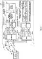
- FIG. 3is a block diagram showing main components of the configuration of a space multiplexing adaptability detection section according to Embodiment 1 of the present invention
- FIG. 4illustrates an example of operation when the base station apparatus according to Embodiment 1 of the present invention carries out a radio communication with a mobile station apparatus;
- FIG. 5is a block diagram showing the configuration of a base station apparatus according to Embodiment 2 of the present invention.
- FIG. 6is a block diagram showing the configuration of a base station apparatus according to Embodiment 3 of the present invention.
- FIG. 7illustrates an example of operation when the base station apparatus according to Embodiment 3 of the present invention carries out a radio communication with a mobile station apparatus
- FIG. 8Aillustrates the frame configuration of an antenna-individuated pilot signal transmitted by means of time division multiplexing from the base station apparatus according to Embodiment 3 of the present invention
- FIG. 8Billustrates the frame configuration of an antenna-individuated pilot signal transmitted by means of code division multiplexing from the base station apparatus according to Embodiment 3 of the present invention
- FIG. 8Cillustrates the frame configuration of an antenna-individuated pilot signal transmitted by means of a combination of time division multiplexing and code division multiplexing from the base station apparatus according to Embodiment 3 of the present invention
- FIG. 9is a block diagram showing the configuration of a base station apparatus according to Embodiment 4 of the present invention.
- FIG. 10is a block diagram showing main components of the configuration of a space multiplexing adaptability detection section according to Embodiment 4 of the present invention.
- FIG. 11is a block diagram showing the configuration of a base station apparatus according to Embodiment 5 of the present invention.
- FIG. 12illustrates a relationship between divided bands and subcarrier signals according to Embodiment 5 of the present invention.
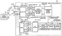
- FIG. 1is a block diagram showing the configuration of a base station apparatus according to Embodiment 1 of the present invention.
- This embodimentwill explain a case with a radio communication system based on a TDD (Time Division Duplex) scheme. Furthermore, this embodiment will explain a case where space multiplexing adaptability is detected based on a reception result at the base station apparatus of a transmission signal from a mobile station apparatus to the base station apparatus (hereinafter referred to as “uplink”) as an example.
- uplinka transmission signal from a mobile station apparatus to the base station apparatus
- Base station apparatus 100 shown in FIG. 1includes Na antennas 102 - 1 to 102 -Na, Na duplexers 104 - 1 to 104 -Na, Na reception system antenna element sections 106 - 1 to 106 -Na, space multiplexing adaptability detection section 108 , transmission format setting section 110 , transmission format formation section 112 , Na serial/parallel conversion (S/P) sections 114 - 1 to 114 -Na and Na transmission system antenna element sections 116 - 1 to 116 -Na.
- S/Pserial/parallel conversion
- reception system antenna element sections 106 - 1 to 106 -Nainclude separators 120 - 1 to 120 -Na respectively.
- Transmission format formation section 112includes coding section 122 , modulation section 124 and space multiplexing section 126 .
- Transmission system antenna element sections 116 - 1 to 116 -Nainclude mixers 128 - 1 to 128 -Na respectively.
- SM-capable mobile station apparatus 150that carries out a radio communication with base station apparatus 100 includes Nr antennas 152 - 1 to 152 -Nr.
- Antennas 102 - 1 to 102 -Naare antennas in common with transmission and reception systems.
- Duplexers 104 - 1 to 104 -Naoutput high-frequency signals S- 1 to S-Na received through antennas 102 - 1 to 102 -Na to separators 120 - 1 to 120 -Na and wirelessly transmits high-frequency signals S- 1 to S-Na input from mixers 128 - 1 to 128 -Na via antennas 102 - 1 to 102 -Na.
- Space multiplexing adaptability detection section 108detects space multiplexing adaptability, that is, adaptability to space multiplexing transmission for each of Nd divided bands DB- 1 to DB-Nd obtained by dividing a communication band to which Ns subcarrier signals f 1 -k to f Ns -k belong into Nd portions (Nd is a natural number: Ns>Nd ⁇ 1) and outputs detection results #1 to #Nd to transmission format setting section 110 .
- the relationship between the divided bands and subcarrier signalsis as shown in FIG. 2 and Nc subcarrier signals exist in divided bands.
- the number of subcarrier signals which belong to the respective divided bandsare different, the number of subcarrier signals which belong to the mth divided band DB-k is expressed as Nc(m) and satisfies the relationship in following (Equation 1).
- FIG. 3only shows the configuration of divided band processing section 156 - 1 that performs processing on divided band DB- 1 for convenience of explanation.
- the configurations of the remaining divided band processing sections 156 - 2 to 156 -Ndare similar to the configuration of divided band processing section 156 - 1 , and therefore explanations thereof will be omitted.
- FIG. 3takes a case where the number of subcarrier signals which belong to one divided band is 2 for example and subcarrier signals f 1 -k, f 2 -k belong to divided band DB- 1 .
- n(m)denotes a subcarrier signal number which belongs to divided band DB-m.
- divided band processing section 156 - mneed not use all subcarrier signals f n(m) -1 to f n(m) -Na which belong to divided band DB-m. For example, it is possible to puncture some of subcarrier signal f n(m) -1 to f n(m) -Na and then carry out processing on divided band DB-m. When the subcarrier signals are punctured, it is difficult to improve the detection accuracy of adaptability to space multiplexing transmission but it is possible to obtain the effect of reducing the amount of processing calculation.
- V n[ h n , 1 h n , 2 ... h n , Na ] T [ Equation ⁇ ⁇ 3 ]
- correlation matrix Rwhen correlation matrix R is generated, as shown in (Equation 4) above, correlation matrix (VnVn H ) (hereinafter referred to as “auto-correlation”) is calculated from correlation vector Vn. Furthermore, correlation matrix R is obtained by integrating auto-correlations. In this embodiment, the auto-correlations are integrated by summing up the auto-correlations associated with the respective subcarrier signals. By so doing, it is possible to emphasize components corresponding to subcarrier signals in higher quality reception states more and improve the accuracy of setting a transmission format.
- Adaptability evaluation function calculation section 190performs eigenvalue expansion of generated correlation matrix R and determines Na eigenvalues ⁇ k . Furthermore, calculated eigenvalues ⁇ k are sorted in descending order and subscripts are assigned from the maximum eigenvalue. Adaptability evaluation function values A and B shown in (Equation 5) and (Equation 6) are generated and detection results #m including them are output as space multiplexing adaptability of divided band DB-m.
- adaptability evaluation function value Ashows a signal to noise ratio (SNR) of a received signal from mobile station apparatus 150 .
- adaptability evaluation function value Bis one measure to evaluate a spatial spread. Note that since correlation matrix R is a Hermitean matrix, its eigenvalues are real numbers.
- a ⁇ ( ⁇ 1 , ⁇ 2 , ⁇ Na )⁇ 1 ⁇ Na [ Equation ⁇ ⁇ 5 ]
- B ⁇ ( ⁇ 1 , ⁇ 2 , ⁇ Na )⁇ 2 - ⁇ Na ⁇ 1 - ⁇ Na [ Equation ⁇ ⁇ 6 ]
- Transmission format setting section 110sets a transmission format in a communication band based on adaptability evaluation function values A, B included in each detection result #m.
- transmission format setting section 110compares adaptability evaluation function values A, B of each divided band DB-m with predetermined numbers respectively. As a result of this comparison, if both adaptability evaluation function values A and B are greater than the predetermined numbers, it is decided that the level of the received signal is high and the spatial spread is large, that is, it is decided to be suitable for space multiplexing transmission and a transmission format is set such that space multiplexing transmission is performed on the downlink.
- a transmission formatis set by determining the space multiplexing number of a communication band, modulation scheme, coding rate and weighting factor for transmission/reception (hereinafter referred to as “transmission/reception weight”).
- transmission/reception weightWhen the space multiplexing number of the communication band is calculated, transmission format setting section 110 calculates a distribution of the space multiplexing numbers corresponding to divided bands DB-m and designates a space multiplexing number which accounts for the largest portion as the space multiplexing number of the communication band.
- transmission format setting section 110generates a transmission format control signal for reporting the set transmission format and outputs the signal to transmission format formation section 112 .
- Transmission format setting section 110may also carry out processing of adaptively changing and setting an M-ary modulation number (modulation scheme) at modulation section 124 and a coding rate at coding section 122 in accordance with adaptability evaluation function value A. For example, since adaptability evaluation function value A indicates an SNR of the received signal, transmission format setting section 110 decreases the coding rate at coding section 122 and increases the M-ary modulation number at modulation section 124 as the channel quality increases. The set M-ary modulation number (modulation scheme) and coding rate are reported as a transmission format control signal to transmission format formation section 112 together with the space multiplexing number.
- the predetermined number used for the comparison with adaptability evaluation function value Bmay be changed in conjunction with adaptability evaluation function value A.
- the predetermined number used for the comparison with adaptability evaluation function value Bmay be decreased as adaptability evaluation function value A increases.
- Coding section 122codes a transmission data sequence based on the coding rate indicated in the transmission format control signal.
- Modulation section 124modulates the coded transmission data sequence based on the M-ary modulation number (modulation scheme) indicated in the transmission format control signal.
- Space multiplexing section 126divides the modulated transmission data sequence into the same number of portions as the space multiplexing number indicated in the transmission format control signal, multiplies each divided transmission data sequence by a transmission weight and outputs the multiplication results to S/P sections 114 - 1 to 114 -Na.
- S/P sections 114 - 1 to 114 -Naconvert in a serial-to-parallel manner the transmission data sequence input from space multiplexing section 126 , whereby the transmission data sequence becomes a multicarrier signal converted to data sequences in a one-to-one correspondence with subcarrier signals.
- Mixers 128 - 1 to 128 -Namix the multicarrier signals input from S/P sections 114 - 1 to 114 -Na and output the mixed signals to duplexers 104 - 1 to 104 -Na.
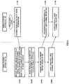
- FIG. 4illustrates an example of operation when base station apparatus 100 wirelessly communicates with mobile station apparatus 150 .
- a procedurewill be explained in a space multiplexing transmission mode in a case of transiting from a normal transmission mode in which a transmission format for space multiplexing transmission is not used to a space multiplexing transmission mode in which the transmission format for space multiplexing transmission is used.
- mobile station apparatus 150transmits antenna-individuated pilot signals for space multiplexing transmission by means of time division or code division from antennas 152 - 1 to 152 -Nr (S 1100 ).
- Correlation calculation section 170 - n - k of base station apparatus 100carries out channel estimation, that is, estimates Nr ⁇ Na channel estimation values h(j, k) (S 1200 ), using the received antenna-individuated pilot signals.
- j1 to Nr.
- adaptability evaluation function calculation section 190estimates reception quality of antennas 102 - 1 to 102 -Na for each mobile station apparatus (S 1300 ).
- Transmission format setting section 110performs singular value decomposition to channel matrix H in which channel estimation value h(j, k) is expressed with a matrix as shown in (Equation 7).
- Right singular value vectors corresponding to Nm singular values ⁇ j in descending orderare designated as transmission weights (transmission weight vectors) for base station apparatus 100
- left singular value vectors corresponding to singular valuesare designated as reception weights (reception weight vectors) at mobile station apparatus 150 .
- Nmis a natural number that satisfies 1 ⁇ Nm ⁇ min(Nr, Na). This makes it possible to perform Nm space multiplexing transmissions.
- the above described operationis carried out for each of the subcarrier signals.
- the reception weights obtainedare reported to mobile station apparatus 150 (S 1400 ).
- Mobile station apparatus 150carries out processing corresponding to reception of data channels (user channels) of individual users based on the reception weights (S 1500 ). Base station apparatus 100 then starts transmission of dedicated user channels based on the transmission weights (S 1600 ) and mobile station apparatus 150 starts reception of the dedicated user channels (S 1700 ).
- the above-described operationmakes it possible to perform space multiplexing transmission in accordance with the detection results of space multiplexing adaptability.
- this embodimenttakes advantage of a high spatial spectrum correlation between adjacent subcarrier signals, divides a communication band into a plurality of divided bands DB- 1 to DB-Nd, combines correlation vectors Vn obtained from subcarrier signals which belong to respective divided bands DB- 1 to DB-Nd to generate correlation matrix R, detects space multiplexing adaptability for each of the divided bands using generated correlation matrix R, and therefore, it is possible to detect a spatial spread of an average arriving path of subcarrier signals which belong to each of the respective divided bands.
- This embodimentsets the transmission format of communication bands at one time, and therefore, it is possible to drastically reduce the amount of processing calculation compared to setting a transmission format for each of the subcarrier signals.
- this embodimentobtains an average spatial spread characteristic of an arriving path of a group of subcarrier signals which belong to each of the divided bands, and therefore, it is possible to introduce an evaluation index for evaluating the spatial characteristic of the group of subcarrier signals into space multiplexing transmission control. Since this evaluation index does not exist in the conventional technique, the conventional technique has no other choice but to set a transmission format for each of the subcarrier signals. Therefore, in a conventional art, a transmission format could be erroneously set when more errors occur in calculations of correlation values of subcarrier signals whose levels are dropped as a result of occurrence of a notch (level drop) in a specific band in the communication band depending on the propagation environment. On the contrary, according to this embodiment, it is possible to set a transmission format in a unit of the group of subcarrier signals by introducing the evaluation index and thereby prevent erroneous settings in the aforementioned case.
- this embodimentallows switching to a space multiplexing transmission mode only when the state of a propagation path is decided to be suitable for space multiplexing transmission, and can thereby prevent drops in the effective transmission rate due to insertion of unnecessary pilot signals in a propagation path unsuitable for space multiplexing transmission, and prevent increases in power consumption due to unnecessary calculation processing.
- the configuration of base station apparatus 100is not limited to the above described one.
- a configuration with which divided bands are changed adaptively in accordance with a propagation environmentmay be added to the above described configuration.
- a configuration with which divided bands are changed based on a correlation bandwidth (coherent bandwidth)may be adopted. This configuration can provide an optimum tradeoff between the accuracy of transmission format setting and the amount of calculation.
- the configuration of space multiplexing adaptability detection section 108is not limited to the above described one.
- a configuration calculating evaluation values on the mobility of mobile station apparatus 150 including an estimated moving speed and Doppler frequency estimate of mobile station apparatus 150may be added to the above described configuration.
- a transmission format that prevents SM transmissionis set to mobile station apparatus 150 . This stabilizes space multiplexing transmission.
- this embodimentexplained the case where the radio communication apparatus of the present invention is applied to base station apparatus 100 and explained the setting of a transmission format on a downlink, but it is also possible to apply the radio communication apparatus of the present invention to mobile station apparatus 150 to thereby enable setting of a transmission format on an uplink.
- adaptability evaluation function values A, Bare not limited to the above described ones.
- adaptability evaluation function value Ait is also possible to use power of a received signal (RSSI: Received Signal Strength Indicator), use an average signal level of a received pilot signal or use an SNR in which S is the average signal level of a received pilot signal and N is a distribution situation of instantaneous pilot received signals.
- adaptability evaluation function value Bmay also be calculated based on the spread of an angle spectrum used to estimate a direction of arrival of paths.
- a( ⁇ )indicates direction vectors of antennas 102 - 1 to 102 -Na and can be expressed as shown in (Equation 9) when antennas 102 - 1 to 102 -Na form an equidistant rectilinear array.
- ddenotes an antenna interval and ⁇ denotes a wavelength in a carrier frequency band.
- a Fourier methodis used, but it is also possible to use an angle spectrum according to an eigenvalue decomposition technique such as a well-known MUSIC method and ESPRIT method or a high resolution technique for estimation of direction of arrival of path, such as Capon method including inverse matrix calculation of a correlation matrix.
- an eigenvalue decomposition techniquesuch as a well-known MUSIC method and ESPRIT method
- Capon methodincluding inverse matrix calculation of a correlation matrix
- a space smoothing techniquemay be applied to correlation matrix R to suppress a correlated wave.
- the number of subcarrier signals which belong to each of the divided bandsis smaller than the number of antennas, the number of ranks of correlation matrix R which is the output of correlation matrix generation section 180 may not become full. For this reason, it is necessary to conveniently select a direction estimation algorithm according to the number of subcarrier signals which belong to each of the divided bands or according to the sum of the number of subcarrier signals and the number of paths.
- antennas 102 - 1 to 102 -Nais an equidistant rectilinear array arrangement
- space smoothing processingto correlation matrix R obtained at correlation matrix generation section 180 or apply processing of estimating the direction of arrival using a beam space which is multiplied by a unitary conversion matrix and whose directional vectors are thus transformed to real numbers.
- Correlation matrix generation section 180may generate correlation vector z shown in (Equation 10) below instead of correlation matrix R shown in (Equation 4) above.
- adaptability evaluation function calculation function 190calculates adaptability evaluation function value A(z) shown in (Equation 11) below instead of adaptability evaluation function value A shown in (Equation 5) above and calculates adaptability evaluation function value B(z) shown in (Equation 12) below instead of adaptability evaluation function value B shown in (Equation 6) above.
- B ⁇ ( z )⁇ z 1 ⁇ ⁇ z 2 ⁇ [ Equation ⁇ ⁇ 12 ]
- adaptability evaluation function value A(z) shown in (Equation 11)is used.
- z kdenotes a kth element in correlation vector z shown in (Equation 10).
- the correlation between the signals received at antennas 102 - 1 to 102 -Na using correlation vector zis evaluated by calculating adaptability evaluation function value B(z) shown in (Equation 12).
- this embodimentexplained the configuration in which correlation matrix R is generated using known pilot signals with a combination of replica generation section 160 , correlation calculation section 170 - n - k and correlation matrix generation section 180 in FIG. 3 , but the internal configuration of space multiplexing adaptability detection section 108 is not limited to this.
- the element (j, k) of correlation matrix Rb calculated herecan be expressed by (Equation 13) below.
- Nbis the predetermined number of pieces of sample data. This technique requires no pilot signals, and can thereby suppress a decrease in the transmission efficiency caused by insertion of pilot signals.
- similar processingis also applicable to correlation vector z.
- the subcarrier signals transmitted as the multicarrier signalsmay also be subcarrier signals which have been subjected to orthogonal frequency division multiplexing.
- frequencies at which subcarrier signals are orthogonal to one another within an OFDM symbol periodare selected and used.
- this embodimentis also applicable to an MC-CDMA (MultiCarrier-Code Division Multiple Access) scheme in which transmission signals are code division multiplexed in the frequency axis direction. In this case, it is possible to realize operations and effects similar to those described above by calculating the correlation value of each subcarrier signal for each user using a pilot signal embedded in the subcarrier signal and multiplexed for each individual user.
- MC-CDMAMultiCarrier-Code Division Multiple Access
- FIG. 5is a block diagram showing the configuration of a base station apparatus according to Embodiment 2 of the present invention.
- the base station apparatus according to this embodimenthas the basic configuration similar to that of the base station apparatus explained in Embodiment 1 and the same components are assigned the same reference numerals and detailed explanations thereof will be omitted.
- the base station apparatus 200 shown in FIG. 5includes Nd transmission format formation sections 112 - 1 to 112 -Nd having the same internal configurations as that of transmission format formation section 112 explained in Embodiment 1, Nd sets of S/P sections 114 - 1 - 1 to 114 - 1 -Na, . . . , 114 -Nd-Na having the same internal configurations as those of S/P sections 114 - 1 to 114 -Na explained in Embodiment 1, transmission format setting section 202 instead of transmission format setting section 110 explained in Embodiment 1 and S/P section 204 that serial/parallel-converts a transmission data sequence to Nd data sequences.
- a feature of the base station apparatus 200 of this embodimentis to set a transmission format of each divided band as opposed to base station apparatus 100 of Embodiment 1 that sets a transmission format of the communication band.
- Transmission format setting section 202sets a transmission format for divided bands based on adaptability evaluation function values A and B included in detection results #m.
- transmission format setting section 202compares adaptability evaluation function values A and B of divided bands DB-m with their respective predetermined numbers. As a result of this comparison, when both adaptability evaluation function values A, B are greater than the predetermined numbers, it is decided that the level of a received signal is high and the spatial spread is large. In other words, it is decided to be suitable for space multiplexing transmission and a transmission format is set such that space multiplexing transmission is performed on a downlink.
- the transmission formatis set by calculating a space multiplexing number, modulation scheme, coding rate and transmission/reception weight for each of the divided bands.
- transmission format setting section 202generates a transmission format control signal for reporting the transmission format set for each divided band and outputs the transmission format control signal to transmission format formation sections 112 - 1 to 112 -Nd.
- transmission format setting section 202may also carry out processing of adaptively changing and setting the M-ary modulation number (modulation scheme) in modulation sections 124 - 1 to 124 -Nd and coding rates in coding sections 122 - 1 to 122 -Nd in accordance with adaptability evaluation function value A. For example, since adaptability evaluation function value A indicates an SNR of a received signal, transmission format setting section 202 decreases the coding rates at coding sections 122 - 1 to 122 -Nd or increases the M-ary modulation number at modulation sections 124 - 1 to 124 -Nd, as the channel quality improves.
- the set M-ary modulation number (modulation scheme) and coding rateare reported to transmission format formation sections 112 - 1 to 112 -Nd as the transmission format control signal together with the space multiplexing number.
- the predetermined number used for a comparison with adaptability evaluation function value Bmay also be changed in conjunction with adaptability evaluation function value A.
- this embodimentmay be adapted in such a way that the predetermined number to be used for the comparison with adaptability evaluation function value B is decreased as adaptability evaluation function value A increases.
- transmission format formation sections 112 - 1 to 112 -Ndform a transmission format for each divided band and output a transmission data sequence space-multiplexed (or not space-multiplexed) for each divided band to mixers 128 - 1 to 128 -Na via the corresponding S/P sections.
- this embodimenttakes advantage of the fact that the correlation in the spatial spectrum between adjacent subcarrier signals is high, divides the communication band into a plurality of divided bands DB- 1 to DB-Nd, combines correlation vectors Vn obtained from each subcarrier signal which belongs to each of the divided bands DB- 1 to DB-Nd to generate correlation matrix R, detects space multiplexing adaptability for each of the divided bands using generated correlation matrix R, and therefore, it is possible to detect a spatial spread of average arriving paths of subcarrier signals which belong to each divided band.
- This embodimentexplained the case where the radio communication apparatus of the present invention is applied to base station apparatus 200 and explained the setting of the transmission format on the downlink, but it is also possible to apply the radio communication apparatus of the present invention to the mobile station apparatus side and thereby set a transmission format on the uplink.
- this embodimentcan also apply a technique of calculating a correlation matrix without using pilot signals as explained using (Equation 13) in Embodiment 1.
- FIG. 6is a block diagram showing the configuration of a base station apparatus according to Embodiment 3 of the present invention.
- the base station apparatus according to this embodimenthas the basic configuration similar to that of base station apparatus 100 explained in Embodiment 1 and the same components are assigned the same reference numerals and explanations thereof will be omitted. Furthermore, this embodiment will explain a case with a radio communication system under an FDD (Frequency Division Duplex) scheme.
- FDDFrequency Division Duplex
- the base station apparatus 300 shown in FIG. 6includes space multiplexing adaptability detection section 302 instead of space multiplexing adaptability detection section 108 explained in Embodiment 1.
- SM-based mobile station apparatus 350that communicates with base station apparatus 300 by radio includes Nr antennas 352 - 1 to 352 -Nr.
- a feature of base station apparatus 300 of this embodimentis to detect space multiplexing adaptability based on feedback information from a mobile station apparatus as opposed to Embodiment 1 in which space multiplexing adaptability is detected based on a result of reception of an uplink signal at the base station apparatus.
- Space multiplexing adaptability detection section 302extracts feedback information from a signal received from the mobile station apparatus 350 .
- the feedback informationis information including a channel estimation value calculated by mobile station apparatus 350 using antenna-individuated pilot signals and measured reception quality.
- space multiplexing adaptability detection section 302generates detection results #1 to #Nd for the respective divided bands using the extracted feedback information and outputs the detection results to transmission format setting section 110 .
- space multiplexing adaptability detection section 302 in mobile station apparatus 350so that detection results #1 to #Nd for the respective divided bands are generated in the mobile station apparatus side and the results may be used as feedback information to the base station apparatus side.
- space multiplexing adaptability detection section 302 and transmission format setting section 110 in mobile station apparatus 350so that detection results #1 to #Nd for the respective divided bands are generated in the mobile station apparatus and the setting results by transmission format setting section 110 may be used as feedback information to the base station apparatus side.
- FIG. 7illustrates an example of the operation when base station apparatus 300 wirelessly communicates with mobile station apparatus 350 .
- a procedurewill be explained in a space multiplexing transmission mode in a case of transiting from a normal transmission mode in which a transmission format for space multiplexing transmission is not used to a space multiplexing transmission mode in which a transmission format for space multiplexing transmission is used.
- base station apparatus 300transmits antenna-individuated pilot signals for space multiplexing transmission from the respective antennas 102 - 1 to 102 -Na (S 3100 ).
- An antenna-individuated pilot signalis made up of a predetermined number of symbols Np.
- FIG. 8A , FIG. 8B and FIG. 8Cshow frame configurations of antenna-individuated pilot signals.
- an antenna-individuated pilot signal AP k having the same pattern or patterns orthogonal to each othere.g., PN signal
- antenna-individuated pilot signal AP kmay be transmitted by means of code division multiplexing.
- antenna-individuated pilot signal AP khas patterns orthogonal to one another among the antennas.
- antenna-individuated pilot signal AP kmay also be transmitted by means of a combination of time division multiplexing and code division multiplexing. That is, in this case, patterns orthogonal to one another are used for antenna-individuated pilot signals (e.g., AP 1 and AP 2 in FIG. 8C ) which share a time division slot of the same time instant are used.
- antenna-individuated pilot signalse.g., AP 1 and AP 2 in FIG. 8C
- By transmitting antenna-individuated pilot signals by means of the combination of time division multiplexing and code division multiplexingit is possible to reduce overhead of time division transmission in a case of the number of antennas Na of base station apparatus 300 being large, which alleviates a reduction of orthogonality in a propagation path during code division multiplexing.
- the space multiplexing number in SMis limited to a value smaller than the number of antennas Na, it is not necessary to use all Na transmission systems. For example, it is also possible to transmit antenna-individuated pilot signals from several ones of antennas 102 - 1 to 102 -Na.
- reception result r j, k (t)a plurality of times and apply averaging processing to the plurality of saved reception results r j, k (t).
- the moving speed of mobile station apparatus 350is sufficiently small, it is possible to reduce the influence of noise and improve the accuracy of channel estimation.
- Mobile station apparatus 350estimates reception quality P(j, k) of antenna-individuated pilot signals and antennas of mobile station apparatus 350 (S 3300 ).
- received signal power, SIR (signal to noise ratio) and SNR or the likemay be used as reception quality, but a case will be explained where SNR is used as an example.
- SNRsignal to noise ratio
- Mobile station apparatus 350then transmits calculated channel estimation value h(j, k) and reception quality P(j, k) to base station apparatus 300 (S 3400 ).
- reception qualityinstead of transmitting Na ⁇ Nr reception quality P(j, k) values, it is also possible to transmit averaged Na ⁇ Nr reception quality P(j, k) values as shown in (Equation 16) below to reduce feedback information. Furthermore, instead of transmitting the averaged value, it is also possible to transmit a median value or maximum value of Na ⁇ Nr reception quality P(j, k) values.
- Space multiplexing adaptability detection section 302 of base station apparatus 300then extracts feedback information including channel estimation value h(j, k) and reception quality P(j, k) from the received signal from mobile station apparatus 350 . Then, transmission format setting section 110 decomposes channel matrix H which expresses channel estimation value h(j, k) in matrix as shown in (Equation 7) into singular values.
- the right singular value vectors corresponding to Nm singular values ⁇ j in descending orderare designated as transmission weights (transmission weight vectors) at base station apparatus 300 and the left singular value vectors corresponding to singular values ⁇ j is designated as reception weight (reception weight vector) at mobile station apparatus 350 . This allows Nm space multiplexing transmission to be performed.
- mobile station apparatus 350carries out reception processing on dedicated user channels to be multiplexed based on the channel estimation result and reception quality calculation result.
- base station apparatus 300detects space multiplexing adaptability for each of the divided bands based on feedback information from mobile station apparatus 350 , and therefore a radio communication system based on an FDD scheme can also realize operations and effects similar to those of Embodiment 1.
- the detection of space multiplexing adaptability for each of the divided bands at base station apparatus 300 based on feedback information from mobile station apparatus 350is also applicable to a radio communication system based on a TDD scheme.
- this embodimentexplained a case where the radio communication apparatus of the present invention is applied to base station apparatus 300 and explained the setting of a transmission format on the downlink, but it is also possible to set a transmission format on the uplink by applying the radio communication apparatus of the present invention to mobile station apparatus 350 .
- this embodimentcan also use a technique of calculating a correlation matrix without using pilot signals.
- FIG. 9is a block diagram showing the configuration of a base station apparatus according to Embodiment 4 of the present invention.
- the base station apparatus according to this embodimenthas the basic configuration similar to that of base station apparatus 100 explained in Embodiment 1 and the same components are assigned the same reference numerals and explanations thereof will be omitted. Furthermore, this embodiment will explain a radio communication system using an MC-CDMA scheme with which each subcarrier signal is directly spread in a time-axis direction.
- Base station apparatus 400 shown in FIG. 9includes space multiplexing adaptability detection section 402 instead of space multiplexing adaptability detection section 108 explained in Embodiment 1.
- a feature of the base station apparatus of this embodimentis to detect path timings using pilot signals embedded in their respective subcarrier signals from a mobile station apparatus and calculate a correlation value to be used for space multiplexing adaptability for each of the path timings detected.
- Space multiplexing adaptability detection section 402detects space multiplexing adaptability for each of Nd divided bands DB- 1 to DB-Nd obtained by dividing the communication band to which Ns subcarrier signals f 1 -k to f Ns -k belong into Nd portions and outputs detection results #1 to #Nd to transmission format setting section 110 .
- Space multiplexing adaptability detection section 402includes Nd divided band processing sections 403 - 1 to 403 -Nd corresponding to divided bands DB-m.
- FIG. 10only shows the configuration of divided band processing section 403 - 1 which processes divided band DB- 1 for convenience of explanation.
- the configurations of the remaining divided band processing sections 403 - 2 to 403 -Ndare similar to the configuration of divided band processing section 403 - 1 and explanations thereof will be omitted.
- FIG. 10shows a case where the number of subcarrier signals which belong to one divided band is 2 as an example and subcarrier signals f 1 -k, f 2 -k belong to divided band DB- 1 .
- Divided band processing section 403 - mincludes path search section 404 - n that detects timings of Ln arriving paths for each of the subcarrier signals using a pilot signal which is a known signal embedded in subcarrier signals f n(m) -k, replica generation sections 406 - n - 1 to 406 - n -Ln that generate replicas of the pilot signals, correlation calculation sections 408 - n - k - 1 to 408 - n - k -Ln that calculate correlation values between reception pilot symbols which are included in subcarrier signals f n(m) -k, and the generated replica, correlation matrix generation section 410 that generates a correlation matrix based on the calculated correlation value, and adaptability evaluation function calculation section 412 that calculates an adaptability evaluation function for evaluating adaptability to space multiplexing transmission based on the generated correlation matrix.
- path search section 404 - nthat detects timings of Ln arriving paths for each of the subcarrier signals using a pilot signal which
- divided band processing section 403 - mneed not use all subcarrier signals f n(m) -k which belong to divided band DB-m as in the case of divided band processing section 156 - m .
- a subcarrier signalis punctured, it is difficult to improve the detection accuracy of adaptability to space multiplexing transmission, but it is possible to obtain an effect of reducing the amount of processing calculation.
- Path search section 404 - ncreates a delay profile using a pilot signal embedded in subcarrier signals f n(m) -k and detects path timings using the delay profile created.
- Correlation value h nk (t j ) at jth path timing t j corresponding to nth subcarrier signal f n -k received at kth antenna 102 - kis expressed in (Equation 17) below.
- a pilot signalis expressed with r(s).
- the delay profileis generated using (1) a method of combining absolute values or squares of correlation value h nk (t j ) of the same timing, (2) a method of generating a plurality of delay profiles by multiplying correlation values h nk (t j ) of the same timing by weights for forming directional beams, summing up the multiplication results and acquiring an absolute value or square thereof, or (3) a method of combining them. Furthermore, it is possible to suppress a noise component by averaging the delay profile over a plurality of frames.
- Correlation matrix generation section 410generates correlation matrix R shown in (Equation 19) using correlation vector Vn shown in (Equation 18) based on calculated correlation value h nk (t j ).
- V n ⁇ ( t j )[ h n , 1 ⁇ ( t j ) h n , 2 ⁇ ( t j ) ... h n , Na ⁇ ( t j ) ] T [ Equation ⁇ ⁇ 18 ]
- Adaptability evaluation function calculation section 412applies an eigenvalue expansion to generated correlation matrix R as in the case of adaptability evaluation function calculation section 190 explained in Embodiment 1 and obtains Na eigenvalues ⁇ k . Furthermore, calculated eigenvalues ⁇ k are sorted in descending order and assigned subscripts are assigned from the maximum one. Adaptability evaluation function values A and B shown in (Equation 5) and (Equation 6) are generated and these are output as detection result #m.
- this embodimentdetects path timings using a pilot signal embedded in each subcarrier signal from mobile station apparatus 150 , calculates a correlation value to be used to detect space multiplexing adaptability for each of the detected path timings, and therefore, it is possible to detect adaptability for each of the divided bands including multipath signals arriving at base station apparatus 400 and improve the detection accuracy by a path diversity effect.
- correlation matrix generation section 410may also generate correlation vector z shown in (Equation 20) below instead of correlation matrix R shown in (Equation 19) above.
- adaptability evaluation function calculation section 412calculates adaptability evaluation function value A(z) shown in (Equation 21) below instead of adaptability evaluation function value A shown in (Equation 18) above and calculates adaptability evaluation function value B(z) shown in (Equation 22) below instead of adaptability evaluation function value B shown in (Equation 19) above.
- adaptability evaluation function value A shown in (Equation 21)is used.
- z kdenotes the kth element in correlation vector z shown in (Equation 20).
- the correlation between the signals received at antennas 102 - 1 to 102 -Nais evaluated using correlation vector z by calculating adaptability evaluation function value B(z) shown in (Equation 22).
- this embodimentexplained a case where the radio communication apparatus of the present invention is applied to base station apparatus 400 and explained the setting of a transmission format on the downlink, but it is also possible to set a transmission format on the uplink by applying the radio communication apparatus of the present invention to the mobile station apparatus side.
- FIG. 11is a block diagram showing the configuration of a base station apparatus according to Embodiment 5 of the present invention.
- the base station apparatus according to this embodimenthas the basic configuration similar to that of base station apparatus 100 explained in Embodiment 1 and the same components are assigned the same reference numerals and explanations thereof will be omitted.
- this embodimentwill explain a radio communication system using a multicarrier scheme under which code division multiplexing is carried out for a plurality of users through spreading in the frequency axis direction.
- Base station apparatus 500 shown in FIG. 11includes divided band changing section 502 in addition to the components of base station apparatus 100 explained in Embodiment 1.
- a feature of the base station apparatus of this embodimentis to change the bandwidths of the divided bands according to a spreading factor for a user channel subjected to code division multiplexing.
- Divided band changing section 502changes the bandwidths of the divided band according to a spreading factor of a user channel subjected to code division multiplexing. That is, when the qth user channel is spread in the frequency axis direction with spreading code sequence Sq(s) of spreading factor SF(q) (that is, when a transmission data sequence is spread using SF(q) subcarrier signals), a group of subcarrier signals used in the spreading processing is considered as one divided band.
- the bandwidth of a divided bandis changed according to spreading factor SF(q)
- the number of the divided bands Nd(q) in the communication bandis variable.
- the relationship between the divided bands and subcarrier signalsis as shown in FIG. 12 .
- the Ns subcarrier signals on the frequency axisare divided into Nd(q) divided bands according to spreading factors SF(q) of user channels.
- NcSF(q) subcarrier signals exist in each divided band.
- this embodimentchanges the bandwidth (number of subcarrier signals) of a divided band according to the spreading factor of users to a plurality of user channels that are code division multiplexed in the frequency axis direction and therefore it is possible to detect space multiplexing adaptability for each channel to be spread and transmitted.
- base station apparatus 500 explained in this embodimentmay also be applied to base station apparatus 200 explained in Embodiment 2. Since base station apparatus 200 sets a transmission format for each of the divided bands, applying the feature of this embodiment makes it possible to set an optimum transmission format for each of the channels to be spread and transmitted and carry out optimum space multiplexing transmission for each channel. In this case, when the mobile station apparatus receives space multiplexed data, it is possible to perform reception processing in units of spreading symbols (or an integer multiple thereof).
- base station apparatus 500 explained in this embodimentmay also be applied to base station apparatus 300 explained in Embodiment 3. In this case, operations and effects similar to those described above can be realized.
- this embodimentexplained the transmission scheme in which a multicarrier signal is spread in the frequency axis direction as an example but the present invention is also applicable to a transmission scheme in which a multicarrier signal is spread in both the frequency axis and time axis directions.
- spreading factor SF(q) of the qth usercan be expressed as the product of spreading factor SF f (q) in the frequency axis direction and spreading factor SF t (q) in the time axis direction as shown in (Equation 23).
- this transmission schemeis applied to base station apparatus 500 , similar operations and effects can be realized by changing the bandwidths of the divided bands based on spreading factor SF+(q) in the frequency axis direction.
- SF( q )SF f ( q ) ⁇ SF t ( q ) [Equation 23]
- the radio communication apparatus and radio communication method according to the present inventionhave the effect of alleviating a burden in setting a transmission format and suppressing increases in the scale of the apparatus, and are suitable for use in a digital radio communication system using a multicarrier scheme.
Landscapes
- Engineering & Computer Science (AREA)
- Signal Processing (AREA)
- Computer Networks & Wireless Communication (AREA)
- Quality & Reliability (AREA)
- Mobile Radio Communication Systems (AREA)
- Radio Transmission System (AREA)
- Digital Transmission Methods That Use Modulated Carrier Waves (AREA)
Abstract
Description
- Non-patent Document 1: “A Study on a Channel Allocation scheme with an Adaptive Array in SDMA”, Ohgane, T., et al., IEEE 47th VTC, pp. 725-729, vol. 2, 1997
- Non-patent Document 2: “Layered Space-Time Architecture for Wireless Communication in a fading environment when using multi-element antennas”, Foschini, G. J., Bell Labs Tech. J, pp. 41-59, Autumn 1996
- Non-Patent Document 3: “On the Capacity of OFDM-based Spatial Multiplexing Systems”, IEEE Trans. Communications, vol. 50, pp. 225-234, 2002
SF(q)=SFf(q)×SFt(q) [Equation 23]
Claims (12)
Priority Applications (2)
| Application Number | Priority Date | Filing Date | Title |
|---|---|---|---|
| US15/859,940US10555305B2 (en) | 2003-07-28 | 2018-01-02 | Transmission apparatus and transmission method using a plurality of divided frequency bands in a communication band |
| US16/729,019US10966203B2 (en) | 2003-07-28 | 2019-12-27 | Transmission apparatus and transmission method using a plurality of divided frequency bands in a communication band |
Applications Claiming Priority (12)
| Application Number | Priority Date | Filing Date | Title |
|---|---|---|---|
| JP2003280557 | 2003-07-28 | ||
| JP2003-280557 | 2003-07-28 | ||
| JP2004-213588 | 2004-07-21 | ||
| JP2004213588AJP4546177B2 (en) | 2003-07-28 | 2004-07-21 | Wireless communication apparatus and wireless communication method |
| PCT/JP2004/010632WO2005011172A1 (en) | 2003-07-28 | 2004-07-26 | Radio communication apparatus and radio communication method |
| US10/565,845US7751369B2 (en) | 2003-07-28 | 2004-07-26 | Radio communication apparatus and radio communication method |
| US12/543,375US7860051B2 (en) | 2003-07-28 | 2009-08-18 | Apparatus and method for radio communication using spatial multiplexing |
| US12/944,552US8009656B2 (en) | 2003-07-28 | 2010-11-11 | Apparatus and method for providing feedback information in response to subcarrier reception |
| US13/185,012US8379620B2 (en) | 2003-07-28 | 2011-07-18 | Transmission apparatus and transmission method using a plurality of divided frequency bands in a communication band |
| US13/683,785US8948114B2 (en) | 2003-07-28 | 2012-11-21 | Transmission apparatus and transmission method using a plurality of divided frequency bands in a communication band |
| US14/577,814US9900890B2 (en) | 2003-07-28 | 2014-12-19 | Transmission apparatus and transmission method using a plurality of divided frequency bands in a communication band |
| US15/859,940US10555305B2 (en) | 2003-07-28 | 2018-01-02 | Transmission apparatus and transmission method using a plurality of divided frequency bands in a communication band |
Related Parent Applications (1)
| Application Number | Title | Priority Date | Filing Date |
|---|---|---|---|
| US14/577,814ContinuationUS9900890B2 (en) | 2003-07-28 | 2014-12-19 | Transmission apparatus and transmission method using a plurality of divided frequency bands in a communication band |
Related Child Applications (1)
| Application Number | Title | Priority Date | Filing Date |
|---|---|---|---|
| US16/729,019ContinuationUS10966203B2 (en) | 2003-07-28 | 2019-12-27 | Transmission apparatus and transmission method using a plurality of divided frequency bands in a communication band |
Publications (2)
| Publication Number | Publication Date |
|---|---|
| US20180146481A1 US20180146481A1 (en) | 2018-05-24 |
| US10555305B2true US10555305B2 (en) | 2020-02-04 |
Family
ID=34106907
Family Applications (9)
| Application Number | Title | Priority Date | Filing Date |
|---|---|---|---|
| US10/565,845Active2025-12-12US7751369B2 (en) | 2003-07-28 | 2004-07-26 | Radio communication apparatus and radio communication method |
| US12/543,375ActiveUS7860051B2 (en) | 2003-07-28 | 2009-08-18 | Apparatus and method for radio communication using spatial multiplexing |
| US12/944,552Expired - LifetimeUS8009656B2 (en) | 2003-07-28 | 2010-11-11 | Apparatus and method for providing feedback information in response to subcarrier reception |
| US13/185,012Expired - LifetimeUS8379620B2 (en) | 2003-07-28 | 2011-07-18 | Transmission apparatus and transmission method using a plurality of divided frequency bands in a communication band |
| US13/185,028Expired - LifetimeUS8428040B2 (en) | 2003-07-28 | 2011-07-18 | Reception apparatus and reception method for setting a format per divided band |
| US13/683,785Expired - LifetimeUS8948114B2 (en) | 2003-07-28 | 2012-11-21 | Transmission apparatus and transmission method using a plurality of divided frequency bands in a communication band |
| US14/577,814Expired - LifetimeUS9900890B2 (en) | 2003-07-28 | 2014-12-19 | Transmission apparatus and transmission method using a plurality of divided frequency bands in a communication band |
| US15/859,940Expired - LifetimeUS10555305B2 (en) | 2003-07-28 | 2018-01-02 | Transmission apparatus and transmission method using a plurality of divided frequency bands in a communication band |
| US16/729,019Expired - LifetimeUS10966203B2 (en) | 2003-07-28 | 2019-12-27 | Transmission apparatus and transmission method using a plurality of divided frequency bands in a communication band |
Family Applications Before (7)
| Application Number | Title | Priority Date | Filing Date |
|---|---|---|---|
| US10/565,845Active2025-12-12US7751369B2 (en) | 2003-07-28 | 2004-07-26 | Radio communication apparatus and radio communication method |
| US12/543,375ActiveUS7860051B2 (en) | 2003-07-28 | 2009-08-18 | Apparatus and method for radio communication using spatial multiplexing |
| US12/944,552Expired - LifetimeUS8009656B2 (en) | 2003-07-28 | 2010-11-11 | Apparatus and method for providing feedback information in response to subcarrier reception |
| US13/185,012Expired - LifetimeUS8379620B2 (en) | 2003-07-28 | 2011-07-18 | Transmission apparatus and transmission method using a plurality of divided frequency bands in a communication band |
| US13/185,028Expired - LifetimeUS8428040B2 (en) | 2003-07-28 | 2011-07-18 | Reception apparatus and reception method for setting a format per divided band |
| US13/683,785Expired - LifetimeUS8948114B2 (en) | 2003-07-28 | 2012-11-21 | Transmission apparatus and transmission method using a plurality of divided frequency bands in a communication band |
| US14/577,814Expired - LifetimeUS9900890B2 (en) | 2003-07-28 | 2014-12-19 | Transmission apparatus and transmission method using a plurality of divided frequency bands in a communication band |
Family Applications After (1)
| Application Number | Title | Priority Date | Filing Date |
|---|---|---|---|
| US16/729,019Expired - LifetimeUS10966203B2 (en) | 2003-07-28 | 2019-12-27 | Transmission apparatus and transmission method using a plurality of divided frequency bands in a communication band |
Country Status (5)
| Country | Link |
|---|---|
| US (9) | US7751369B2 (en) |
| EP (5) | EP2547006A1 (en) |
| JP (1) | JP4546177B2 (en) |
| CN (2) | CN1830169B (en) |
| WO (1) | WO2005011172A1 (en) |
Families Citing this family (39)
| Publication number | Priority date | Publication date | Assignee | Title |
|---|---|---|---|---|
| JP4546177B2 (en)* | 2003-07-28 | 2010-09-15 | パナソニック株式会社 | Wireless communication apparatus and wireless communication method |
| CN101027863B (en) | 2004-09-27 | 2012-06-27 | 夏普株式会社 | wireless transmitter |
| CN101023612A (en)* | 2004-09-28 | 2007-08-22 | 松下电器产业株式会社 | Multicarrier communication apparatus and multicarrier communication method |
| US7564914B2 (en)* | 2004-12-14 | 2009-07-21 | Broadcom Corporation | Method and system for frame formats for MIMO channel measurement exchange |
| JP2006270730A (en)* | 2005-03-25 | 2006-10-05 | Kyocera Corp | Wireless communication method, wireless communication system, and wireless communication apparatus |
| EP1860792A1 (en)* | 2005-03-30 | 2007-11-28 | Matsusita Electric Industrial Co., Ltd. | Wireless communication method, wireless communication system, and wireless communication device |
| US8565194B2 (en)* | 2005-10-27 | 2013-10-22 | Qualcomm Incorporated | Puncturing signaling channel for a wireless communication system |
| JP4788879B2 (en)* | 2005-07-08 | 2011-10-05 | 日本電気株式会社 | RADIO COMMUNICATION SYSTEM, RECEPTION DEVICE USING A plurality of antennas, DEMODULATION METHOD USED FOR THEM, AND PROGRAM THEREOF |
| EP1917748B1 (en)* | 2005-08-26 | 2018-02-28 | NEC Corporation | Adaptive pilot structure to assist channel estimation in spread spectrum systems |
| CN100358261C (en)* | 2005-09-13 | 2007-12-26 | 北京交通大学 | An array antenna MC-CDMA system uplink receiving method |
| US20070149132A1 (en) | 2005-12-22 | 2007-06-28 | Junyl Li | Methods and apparatus related to selecting control channel reporting formats |
| JP4958565B2 (en)* | 2006-01-06 | 2012-06-20 | パナソニック株式会社 | Wireless communication device |
| KR100913089B1 (en) | 2006-02-07 | 2009-08-21 | 엘지전자 주식회사 | Method for Transmitting Pilot for Multiple Carrier System |
| JP4727678B2 (en)* | 2006-02-08 | 2011-07-20 | 富士通株式会社 | Wireless communication system using multi-antenna transmission technology and multi-user scheduler applied to the same |
| KR101376867B1 (en) | 2006-03-03 | 2014-03-20 | 닛본 덴끼 가부시끼가이샤 | Multi-input multi-output communication system, transmitter, and resource allocation method in them |
| JP2007300383A (en) | 2006-04-28 | 2007-11-15 | Fujitsu Ltd | MIMO-OFDM transmitter |
| MX2009001250A (en) | 2006-08-07 | 2009-04-07 | Interdigital Tech Corp | Method, apparatus and system for implementing multi-user virtual multiple-input multiple-output. |
| JP4837638B2 (en)* | 2006-08-29 | 2011-12-14 | パナソニック株式会社 | MIMO antenna apparatus and wireless communication apparatus including the same |
| US8209150B2 (en) | 2006-11-23 | 2012-06-26 | New Jersey Institute Of Technology | Mobile speed and doppler frequency estimation using cyclostationarity |
| CN102685057B (en)* | 2007-09-12 | 2015-06-17 | 夏普株式会社 | Transmission apparatus and method, processor, OFDM transmission apparatus and method, and wireless communication system |
| US8462714B2 (en) | 2007-10-01 | 2013-06-11 | Ntt Docomo, Inc. | Base station, transmission method, mobile station, and reception method |
| US20090232116A1 (en)* | 2008-03-11 | 2009-09-17 | Li Guoqing C | Mechanism to avoid interference and improve channel efficiency in mmwave wpans |
| US8406280B2 (en) | 2008-03-18 | 2013-03-26 | Argon St, Inc. | System and method for mitigating severe multipath interference for geolocation and navigation |
| CN102474736B (en)* | 2009-07-09 | 2014-12-10 | 日本电信电话株式会社 | Wireless communication method, wireless communication system, wireless base station, and wireless terminal station |
| US8385837B2 (en)* | 2009-07-15 | 2013-02-26 | Mitsubishi Electric Corporation | Mobile receiver apparatus |
| US8315183B2 (en)* | 2009-12-23 | 2012-11-20 | Intel Corporation | Channel quality indexing and reverse indexing |
| CN102474315B (en)* | 2010-01-27 | 2014-04-23 | 中兴通讯股份有限公司 | Multiple input multiple output and beam-forming data transmission method and device |
| US8588205B2 (en)* | 2010-02-12 | 2013-11-19 | Mediatek Inc. | Uplink power control message indexing in wireless OFDMA systems |
| US8654728B2 (en)* | 2011-04-29 | 2014-02-18 | Telefonaktiebolaget L M Ericsson (Publ) | Generating uplink signals from user equipment nodes to identify interferers to a network node |
| KR101269502B1 (en)* | 2011-12-14 | 2013-05-30 | 한국전자통신연구원 | Apparatus and method for secret key generation with varying wireless channel status in wireless communication networks |
| JP5923786B2 (en)* | 2012-03-16 | 2016-05-25 | シャープ株式会社 | Base station apparatus and communication method |
| GB2502108B (en)* | 2012-05-16 | 2014-10-15 | Canon Kk | Reception quality assessment |
| US20150318968A1 (en)* | 2012-12-10 | 2015-11-05 | Lg Electronics Inc. | Method for transmitting system information in wireless access system supporting ultrahigh frequency and device for supporting same |
| CN103684687B (en)* | 2013-11-18 | 2017-02-01 | 北京交通大学 | Mine roadway uplink MC-CDMA wireless transmission cooperation method |
| JP2017069688A (en)* | 2015-09-29 | 2017-04-06 | パナソニックIpマネジメント株式会社 | Transmitting apparatus, receiving apparatus, and communication method using them |
| JP7091617B2 (en)* | 2017-08-02 | 2022-06-28 | 富士通株式会社 | Optical receiver, optical transmission system, and reception processing method |
| CN107503720A (en)* | 2017-09-08 | 2017-12-22 | 西安思坦仪器股份有限公司 | A kind of device and method for regulating and controlling seperated layer water injection using flow waves |
| CN109818633B (en)* | 2018-12-19 | 2021-03-02 | 武汉船舶通信研究所(中国船舶重工集团公司第七二二研究所) | Signal transmission method and device based on SCPC array and symbol space synthesis |
| US12199710B2 (en) | 2020-03-19 | 2025-01-14 | Nippon Telegraph And Telephone Corporation | Wireless communication method and wireless communication system |
Citations (44)
| Publication number | Priority date | Publication date | Assignee | Title |
|---|---|---|---|---|
| US5530655A (en) | 1989-06-02 | 1996-06-25 | U.S. Philips Corporation | Digital sub-band transmission system with transmission of an additional signal |
| US5625880A (en) | 1991-12-12 | 1997-04-29 | Arraycomm, Incorporated | Spectrally efficient and high capacity acknowledgement radio paging system |
| US5828658A (en) | 1991-12-12 | 1998-10-27 | Arraycomm, Inc. | Spectrally efficient high capacity wireless communication systems with spatio-temporal processing |
| US5914933A (en) | 1996-03-08 | 1999-06-22 | Lucent Technologies Inc. | Clustered OFDM communication system |
| US6067290A (en) | 1999-07-30 | 2000-05-23 | Gigabit Wireless, Inc. | Spatial multiplexing in a cellular network |
| US6088592A (en) | 1996-03-25 | 2000-07-11 | Airnet Communications Corporation | Wireless system plan using in band-translators with diversity backhaul to enable efficient depolyment of high capacity base transceiver systems |
| US6144711A (en) | 1996-08-29 | 2000-11-07 | Cisco Systems, Inc. | Spatio-temporal processing for communication |
| US20010013091A1 (en) | 1999-12-30 | 2001-08-09 | Dietmar Koschella | Circuit arrangement and a method for creating and retrieveing replacement data |
| US20010014091A1 (en) | 1999-08-02 | 2001-08-16 | Mitsubishi Denki Kabushiki Kaisha | Mobile communication system, base station, mobile communication terminal, and retransmission control method |
| US6351499B1 (en) | 1999-12-15 | 2002-02-26 | Iospan Wireless, Inc. | Method and wireless systems using multiple antennas and adaptive control for maximizing a communication parameter |
| EP1185001A2 (en) | 2000-09-01 | 2002-03-06 | Nortel Networks Limited | Adaptive time deversity and spatial diversity for OFDM |
| US6377566B1 (en) | 1998-03-30 | 2002-04-23 | Agere Systems Guardian Corp. | OFDM subcarrier hopping in a multi service OFDM system |
| JP2002246958A (en) | 2001-02-20 | 2002-08-30 | Mitsubishi Electric Corp | Mobile communication system, multi-carrier CDMA transmitting apparatus, and multi-carrier CDMA receiving apparatus |
| US6473467B1 (en) | 2000-03-22 | 2002-10-29 | Qualcomm Incorporated | Method and apparatus for measuring reporting channel state information in a high efficiency, high performance communications system |
| US20020191535A1 (en) | 2001-04-09 | 2002-12-19 | Nippon Telegraph And Telephone Corporation | OFDM signal communication system, OFDM signal transmitting device and OFDM signal receiving device |
| JP2002374224A (en) | 2001-04-09 | 2002-12-26 | Nippon Telegr & Teleph Corp <Ntt> | OFDM signal transmission system, OFDM signal transmission device, and OFDM signal reception device |
| JP2003069531A (en) | 2001-08-23 | 2003-03-07 | Mitsubishi Electric Corp | Mobile communication system, multi-carrier CDMA transmitting apparatus, and multi-carrier CDMA receiving apparatus |
| US20030060165A1 (en) | 2001-09-26 | 2003-03-27 | Koji Horisaki | Multi-carrier communication apparatus |
| JP2003158499A (en) | 2001-11-20 | 2003-05-30 | Mitsubishi Electric Corp | Communication method and communication device |
| JP2003169036A (en) | 2001-11-30 | 2003-06-13 | Japan Telecom Co Ltd | Orthogonal frequency-division multiplex system and transmitter/receiver |
| US20030133426A1 (en)* | 2000-09-29 | 2003-07-17 | Brett Schein | Selecting random access channels |
| US20030169722A1 (en) | 2000-09-29 | 2003-09-11 | Paul Petrus | Frame structure for radio communications system |
| US6661351B1 (en) | 1998-08-05 | 2003-12-09 | Ccp Co., Ltd. | Radio control system and radio control method |
| US20030235255A1 (en)* | 2002-06-24 | 2003-12-25 | Ketchum John W. | Signal processing with channel eigenmode decomposition and channel inversion for MIMO systems |
| US20040022205A1 (en) | 2000-08-25 | 2004-02-05 | Takeo Miyata | Radio base station and program for radio base station |
| US20040082356A1 (en) | 2002-10-25 | 2004-04-29 | Walton J. Rodney | MIMO WLAN system |
| US20040178954A1 (en)* | 2003-03-13 | 2004-09-16 | Vook Frederick W. | Method and apparatus for multi-antenna transmission |
| US20040192218A1 (en) | 2003-03-31 | 2004-09-30 | Oprea Alexandru M. | System and method for channel data transmission in wireless communication systems |
| US6870808B1 (en) | 2000-10-18 | 2005-03-22 | Adaptix, Inc. | Channel allocation in broadband orthogonal frequency-division multiple-access/space-division multiple-access networks |
| US6922445B1 (en) | 1999-12-15 | 2005-07-26 | Intel Corporation | Method and system for mode adaptation in wireless communication |
| US6947748B2 (en) | 2000-12-15 | 2005-09-20 | Adaptix, Inc. | OFDMA with adaptive subcarrier-cluster configuration and selective loading |
| US6999467B2 (en) | 2003-07-28 | 2006-02-14 | Motorola, Inc. | Method and apparatus for transmission and reception within an OFDM communication system |
| US7027523B2 (en) | 2001-06-22 | 2006-04-11 | Qualcomm Incorporated | Method and apparatus for transmitting data in a time division duplexed (TDD) communication system |
| US7069009B2 (en) | 2002-09-30 | 2006-06-27 | Samsung Electronics Co., Ltd | Apparatus and method for allocating resources of a virtual cell in an OFDM mobile communication system |
| US7092431B2 (en) | 2001-12-28 | 2006-08-15 | Ntt Docomo, Inc. | Receiver, transmitter, communication system, and method of communication |
| US7126996B2 (en) | 2001-12-28 | 2006-10-24 | Motorola, Inc. | Adaptive transmission method |
| US7130592B2 (en) | 2001-10-31 | 2006-10-31 | Matsushita Electric Industrial Co., Ltd. | Radio transmission apparatus and radio communication method |
| US7203508B2 (en) | 2001-06-13 | 2007-04-10 | Ntt Docomo, Inc. | Mobile communication systems, mobile communication methods, base stations, mobile stations, and signal transmission methods in the mobile communication systems |
| US7233625B2 (en) | 2000-09-01 | 2007-06-19 | Nortel Networks Limited | Preamble design for multiple input—multiple output (MIMO), orthogonal frequency division multiplexing (OFDM) system |
| US20070177681A1 (en) | 2003-12-27 | 2007-08-02 | In-Kyeong Choi | Mimo-ofdm system using eigenbeamforming method |
| US7286540B2 (en) | 2001-08-23 | 2007-10-23 | Samsung Electronics Co., Ltd. | Method for allocating HARQ channel number for indicating state information in an HSDPA communication system |
| US7420915B2 (en) | 2001-08-27 | 2008-09-02 | Matsushita Electric Industrial Co. ,Ltd. | Radio communications apparatus and radio communications method |
| US7573805B2 (en) | 2001-12-28 | 2009-08-11 | Motorola, Inc. | Data transmission and reception method and apparatus |
| US7751369B2 (en) | 2003-07-28 | 2010-07-06 | Panasonic Corporation | Radio communication apparatus and radio communication method |
Family Cites Families (9)
| Publication number | Priority date | Publication date | Assignee | Title |
|---|---|---|---|---|
| US7158493B1 (en)* | 2000-09-29 | 2007-01-02 | Arraycomm, Llc | Radio communications system with a minimal broadcast channel |
| JP3888189B2 (en)* | 2002-03-12 | 2007-02-28 | 松下電器産業株式会社 | Adaptive antenna base station equipment |
| JP4046267B2 (en) | 2002-03-26 | 2008-02-13 | 株式会社半導体エネルギー研究所 | Display device |
| JP4227468B2 (en)* | 2002-06-24 | 2009-02-18 | キヤノン株式会社 | Image forming apparatus and method, and control program |
| JP4097129B2 (en)* | 2002-08-08 | 2008-06-11 | 三菱電機株式会社 | Wireless transmission device and wireless device |
| JP4309110B2 (en)* | 2002-09-27 | 2009-08-05 | パナソニック株式会社 | Adaptive antenna wireless communication device |
| JP2004213588A (en) | 2003-01-09 | 2004-07-29 | Seiko Epson Corp | Semiconductor device |
| JP4287670B2 (en)* | 2003-02-18 | 2009-07-01 | パナソニック株式会社 | Communication apparatus and communication method |
| JP2005006287A (en)* | 2003-05-20 | 2005-01-06 | Hitachi Ltd | Pilot signal transmission / reception method, base station apparatus, and terminal apparatus |
- 2004
- 2004-07-21JPJP2004213588Apatent/JP4546177B2/ennot_activeExpired - Lifetime
- 2004-07-26EPEP20120179870patent/EP2547006A1/ennot_activeWithdrawn
- 2004-07-26EPEP12179868.0Apatent/EP2523364B1/ennot_activeExpired - Lifetime
- 2004-07-26CNCN2004800220947Apatent/CN1830169B/ennot_activeExpired - Lifetime
- 2004-07-26EPEP12179869.8Apatent/EP2547005B1/ennot_activeExpired - Lifetime
- 2004-07-26WOPCT/JP2004/010632patent/WO2005011172A1/ennot_activeCeased
- 2004-07-26CNCN2010101059485Apatent/CN101882949B/ennot_activeExpired - Lifetime
- 2004-07-26USUS10/565,845patent/US7751369B2/enactiveActive
- 2004-07-26EPEP04770943.1Apatent/EP1646172B1/ennot_activeExpired - Lifetime
- 2004-07-26EPEP19179125.0Apatent/EP3567745B1/ennot_activeExpired - Lifetime
- 2009
- 2009-08-18USUS12/543,375patent/US7860051B2/enactiveActive
- 2010
- 2010-11-11USUS12/944,552patent/US8009656B2/ennot_activeExpired - Lifetime
- 2011
- 2011-07-18USUS13/185,012patent/US8379620B2/ennot_activeExpired - Lifetime
- 2011-07-18USUS13/185,028patent/US8428040B2/ennot_activeExpired - Lifetime
- 2012
- 2012-11-21USUS13/683,785patent/US8948114B2/ennot_activeExpired - Lifetime
- 2014
- 2014-12-19USUS14/577,814patent/US9900890B2/ennot_activeExpired - Lifetime
- 2018
- 2018-01-02USUS15/859,940patent/US10555305B2/ennot_activeExpired - Lifetime
- 2019
- 2019-12-27USUS16/729,019patent/US10966203B2/ennot_activeExpired - Lifetime
Patent Citations (57)
| Publication number | Priority date | Publication date | Assignee | Title |
|---|---|---|---|---|
| US5530655A (en) | 1989-06-02 | 1996-06-25 | U.S. Philips Corporation | Digital sub-band transmission system with transmission of an additional signal |
| US5625880A (en) | 1991-12-12 | 1997-04-29 | Arraycomm, Incorporated | Spectrally efficient and high capacity acknowledgement radio paging system |
| US5828658A (en) | 1991-12-12 | 1998-10-27 | Arraycomm, Inc. | Spectrally efficient high capacity wireless communication systems with spatio-temporal processing |
| US5914933A (en) | 1996-03-08 | 1999-06-22 | Lucent Technologies Inc. | Clustered OFDM communication system |
| US6088592A (en) | 1996-03-25 | 2000-07-11 | Airnet Communications Corporation | Wireless system plan using in band-translators with diversity backhaul to enable efficient depolyment of high capacity base transceiver systems |
| US6144711A (en) | 1996-08-29 | 2000-11-07 | Cisco Systems, Inc. | Spatio-temporal processing for communication |
| US6377566B1 (en) | 1998-03-30 | 2002-04-23 | Agere Systems Guardian Corp. | OFDM subcarrier hopping in a multi service OFDM system |
| US6661351B1 (en) | 1998-08-05 | 2003-12-09 | Ccp Co., Ltd. | Radio control system and radio control method |
| US6067290A (en) | 1999-07-30 | 2000-05-23 | Gigabit Wireless, Inc. | Spatial multiplexing in a cellular network |
| US20010014091A1 (en) | 1999-08-02 | 2001-08-16 | Mitsubishi Denki Kabushiki Kaisha | Mobile communication system, base station, mobile communication terminal, and retransmission control method |
| US6351499B1 (en) | 1999-12-15 | 2002-02-26 | Iospan Wireless, Inc. | Method and wireless systems using multiple antennas and adaptive control for maximizing a communication parameter |
| US6922445B1 (en) | 1999-12-15 | 2005-07-26 | Intel Corporation | Method and system for mode adaptation in wireless communication |
| US20010013091A1 (en) | 1999-12-30 | 2001-08-09 | Dietmar Koschella | Circuit arrangement and a method for creating and retrieveing replacement data |
| US6473467B1 (en) | 2000-03-22 | 2002-10-29 | Qualcomm Incorporated | Method and apparatus for measuring reporting channel state information in a high efficiency, high performance communications system |
| US7623488B2 (en) | 2000-08-25 | 2009-11-24 | Kyocera Corporation | Radio base station and program for radio base station |
| US20040022205A1 (en) | 2000-08-25 | 2004-02-05 | Takeo Miyata | Radio base station and program for radio base station |
| US7233625B2 (en) | 2000-09-01 | 2007-06-19 | Nortel Networks Limited | Preamble design for multiple input—multiple output (MIMO), orthogonal frequency division multiplexing (OFDM) system |
| EP1185001A2 (en) | 2000-09-01 | 2002-03-06 | Nortel Networks Limited | Adaptive time deversity and spatial diversity for OFDM |
| US6985434B2 (en) | 2000-09-01 | 2006-01-10 | Nortel Networks Limited | Adaptive time diversity and spatial diversity for OFDM |
| US20020122383A1 (en) | 2000-09-01 | 2002-09-05 | Shiquan Wu | Adaptive time diversity and spatial diversity for OFDM |
| US20030133426A1 (en)* | 2000-09-29 | 2003-07-17 | Brett Schein | Selecting random access channels |
| US20030169722A1 (en) | 2000-09-29 | 2003-09-11 | Paul Petrus | Frame structure for radio communications system |
| US6870808B1 (en) | 2000-10-18 | 2005-03-22 | Adaptix, Inc. | Channel allocation in broadband orthogonal frequency-division multiple-access/space-division multiple-access networks |
| US6947748B2 (en) | 2000-12-15 | 2005-09-20 | Adaptix, Inc. | OFDMA with adaptive subcarrier-cluster configuration and selective loading |
| JP2002246958A (en) | 2001-02-20 | 2002-08-30 | Mitsubishi Electric Corp | Mobile communication system, multi-carrier CDMA transmitting apparatus, and multi-carrier CDMA receiving apparatus |
| US20040076172A1 (en) | 2001-02-20 | 2004-04-22 | Hiroyasu Sano | Mobile communication system, multicarrier cdma transmitter, and multicarrier cdma receiver |
| US20020191535A1 (en) | 2001-04-09 | 2002-12-19 | Nippon Telegraph And Telephone Corporation | OFDM signal communication system, OFDM signal transmitting device and OFDM signal receiving device |
| JP2002374224A (en) | 2001-04-09 | 2002-12-26 | Nippon Telegr & Teleph Corp <Ntt> | OFDM signal transmission system, OFDM signal transmission device, and OFDM signal reception device |
| US7203508B2 (en) | 2001-06-13 | 2007-04-10 | Ntt Docomo, Inc. | Mobile communication systems, mobile communication methods, base stations, mobile stations, and signal transmission methods in the mobile communication systems |
| US7027523B2 (en) | 2001-06-22 | 2006-04-11 | Qualcomm Incorporated | Method and apparatus for transmitting data in a time division duplexed (TDD) communication system |
| US20040037262A1 (en) | 2001-08-23 | 2004-02-26 | Kazuo Tanada | Mobile communication system mult-icarrier cdma transmitting apparatus and multi-carrier cdma reception apparatus |
| US7286540B2 (en) | 2001-08-23 | 2007-10-23 | Samsung Electronics Co., Ltd. | Method for allocating HARQ channel number for indicating state information in an HSDPA communication system |
| JP2003069531A (en) | 2001-08-23 | 2003-03-07 | Mitsubishi Electric Corp | Mobile communication system, multi-carrier CDMA transmitting apparatus, and multi-carrier CDMA receiving apparatus |
| US7420915B2 (en) | 2001-08-27 | 2008-09-02 | Matsushita Electric Industrial Co. ,Ltd. | Radio communications apparatus and radio communications method |
| JP2003110517A (en) | 2001-09-26 | 2003-04-11 | Toshiba Corp | Multi-carrier communication device |
| US20030060165A1 (en) | 2001-09-26 | 2003-03-27 | Koji Horisaki | Multi-carrier communication apparatus |
| US7130592B2 (en) | 2001-10-31 | 2006-10-31 | Matsushita Electric Industrial Co., Ltd. | Radio transmission apparatus and radio communication method |
| JP2003158499A (en) | 2001-11-20 | 2003-05-30 | Mitsubishi Electric Corp | Communication method and communication device |
| JP2003169036A (en) | 2001-11-30 | 2003-06-13 | Japan Telecom Co Ltd | Orthogonal frequency-division multiplex system and transmitter/receiver |
| US7573805B2 (en) | 2001-12-28 | 2009-08-11 | Motorola, Inc. | Data transmission and reception method and apparatus |
| US7092431B2 (en) | 2001-12-28 | 2006-08-15 | Ntt Docomo, Inc. | Receiver, transmitter, communication system, and method of communication |
| US7126996B2 (en) | 2001-12-28 | 2006-10-24 | Motorola, Inc. | Adaptive transmission method |
| US20030235255A1 (en)* | 2002-06-24 | 2003-12-25 | Ketchum John W. | Signal processing with channel eigenmode decomposition and channel inversion for MIMO systems |
| US7069009B2 (en) | 2002-09-30 | 2006-06-27 | Samsung Electronics Co., Ltd | Apparatus and method for allocating resources of a virtual cell in an OFDM mobile communication system |
| US20040082356A1 (en) | 2002-10-25 | 2004-04-29 | Walton J. Rodney | MIMO WLAN system |
| US20040178954A1 (en)* | 2003-03-13 | 2004-09-16 | Vook Frederick W. | Method and apparatus for multi-antenna transmission |
| US6927728B2 (en) | 2003-03-13 | 2005-08-09 | Motorola, Inc. | Method and apparatus for multi-antenna transmission |
| US20040192218A1 (en) | 2003-03-31 | 2004-09-30 | Oprea Alexandru M. | System and method for channel data transmission in wireless communication systems |
| US7751369B2 (en) | 2003-07-28 | 2010-07-06 | Panasonic Corporation | Radio communication apparatus and radio communication method |
| US6999467B2 (en) | 2003-07-28 | 2006-02-14 | Motorola, Inc. | Method and apparatus for transmission and reception within an OFDM communication system |
| US7860051B2 (en) | 2003-07-28 | 2010-12-28 | Panasonic Corporation | Apparatus and method for radio communication using spatial multiplexing |
| US8009656B2 (en) | 2003-07-28 | 2011-08-30 | Panasonic Corporation | Apparatus and method for providing feedback information in response to subcarrier reception |
| US8379620B2 (en)* | 2003-07-28 | 2013-02-19 | Panasonic Corporation | Transmission apparatus and transmission method using a plurality of divided frequency bands in a communication band |
| US8428040B2 (en) | 2003-07-28 | 2013-04-23 | Panasonic Corporation | Reception apparatus and reception method for setting a format per divided band |
| US8948114B2 (en)* | 2003-07-28 | 2015-02-03 | Panasonic Intellectual Property Corporation Of America | Transmission apparatus and transmission method using a plurality of divided frequency bands in a communication band |
| US9900890B2 (en)* | 2003-07-28 | 2018-02-20 | Optis Wireless Technology, Llc | Transmission apparatus and transmission method using a plurality of divided frequency bands in a communication band |
| US20070177681A1 (en) | 2003-12-27 | 2007-08-02 | In-Kyeong Choi | Mimo-ofdm system using eigenbeamforming method |
Non-Patent Citations (33)
| Title |
|---|
| Advisory Action dated Apr. 9, 2009 in U.S. Appl. No. 10/565,845. |
| Bolcskei et al., "On the Capacity of OFDM-Based Spatial Multiplexing Systems," IEEE Transactions on Communications 50(2):225-234, Feb. 2002. |
| European Communication Under Rule 71(3) EPC dated Jan. 15, 2019 in EP Application 12179869.8. |
| European Intention to Grant dated Feb. 8, 2018 in EP Application 12179868.0. |
| European Intention to Grant dated Feb. 9, 2018 in EP Application 12179868.8. |
| European Office Action dated Mar. 16, 2017 in EP Application 12179868.0. |
| European Office Action dated Mar. 16, 2017 in EP Application 12179868.8. |
| European Summons to Attend Oral Proceedings Pursuant to Rule 115(1) EPC dated Jul. 17, 2018 in EP Application 12179868.8. |
| Extended European Search Report, dated Oct. 2, 2012, for European Application No. 12179868.0-2415, 9 pages. |
| Final Office Action dated Apr. 9, 2012 in U.S. Appl. No. 13/185,012. |
| Final Office Action dated Jan. 12, 2009 in U.S. Appl. No. 10/565,845. |
| Final Office Action dated Jul. 14, 2010 in U.S. Appl. No. 12/543,375. |
| Final Office Action dated Jun. 19, 2017 in U.S. Appl. No. 14/577,814. |
| Foschini, "Layered Space-Time Architecture for Wireless Communication in a Fading Environment When Using Multi-Element Antennas," Bell Labs Technical Journal: 41-59, Autumn 1996. |
| International Search Report, dated Nov. 9, 2004, for International Application No. PCT/JP2004/010632, 2 pages. |
| Jing et al., "Performance Study of Adaptive Modulation/Coding in MIMO-OFDM System," CCGEI 2003, Montreal, CA, pp. 1559-1562. |
| LG Electronics, Inc., "Multi-Stream Beamforming (MSB) MIMO System," R1-030581, Agenda Item: 6. MIMO, 3GPP TSG RAN WG1 #32, Paris, France, May 19-23, 2003, 10 pages. |
| Notice of Allowance dated Apr. 2, 2010 in U.S. Appl. No. 10/565,845. |
| Notice of Allowance dated Apr. 25, 2011 in U.S. Appl. No. 12/944,552. |
| Notice of Allowance dated Aug. 19, 2010 in U.S. Appl. No. 12/543,375. |
| Notice of Allowance dated Aug. 23, 2012 in U.S. Appl. No. 13/185,012. |
| Notice of Allowance dated Jan. 4, 2013 in U.S. Appl. No. 13/185,012. |
| Notice of Allowance dated Oct. 21, 2014 in U.S. Appl. No. 13/683,785. |
| Notice of Allowance dated Oct. 5, 2017 in U.S. Appl. No. 14/577,814. |
| Office Action dated Feb. 22, 2010 in U.S. Appl. No. 12/543,375. |
| Office Action dated Feb. 6, 2017 in U.S. Appl. No. 14/577,814. |
| Office Action dated Jan. 5, 2011 in U.S. Appl. No. 12/944,552. |
| Office Action dated Jun. 25, 2008 in U.S. Appl. No. 10/565,845. |
| Office Action dated Jun. 25, 2014 in U.S. Appl. No. 13/683,785. |
| Office Action dated May 26, 2009 in U.S. Appl. No. 10/565,845. |
| Office Action dated Nov. 16, 2009 in U.S. Appl. No. 10/565,845. |
| Office Action dated Nov. 9, 2011 in U.S. Appl. No. 13/185,012. |
| Ohgane et al., "A Study on a Channel Allocation Scheme with an Adaptive Array in SOMA," IEEE 47th VTC, vol. 2, 1997, pp. 725-729. |
Also Published As
| Publication number | Publication date |
|---|---|
| EP1646172B1 (en) | 2015-09-16 |
| US20120044953A1 (en) | 2012-02-23 |
| US20110058574A1 (en) | 2011-03-10 |
| US8428040B2 (en) | 2013-04-23 |
| CN101882949B (en) | 2013-02-13 |
| CN101882949A (en) | 2010-11-10 |
| US8948114B2 (en) | 2015-02-03 |
| US20200146013A1 (en) | 2020-05-07 |
| US20150103690A1 (en) | 2015-04-16 |
| US20180146481A1 (en) | 2018-05-24 |
| US8379620B2 (en) | 2013-02-19 |
| US7751369B2 (en) | 2010-07-06 |
| EP2523364B1 (en) | 2018-07-18 |
| EP2547005B1 (en) | 2019-06-19 |
| EP3567745A1 (en) | 2019-11-13 |
| EP2523364A1 (en) | 2012-11-14 |
| US9900890B2 (en) | 2018-02-20 |
| US8009656B2 (en) | 2011-08-30 |
| EP1646172A4 (en) | 2012-01-11 |
| US20060193298A1 (en) | 2006-08-31 |
| JP4546177B2 (en) | 2010-09-15 |
| JP2005065242A (en) | 2005-03-10 |
| EP3567745B1 (en) | 2022-02-16 |
| US20130083760A1 (en) | 2013-04-04 |
| CN1830169B (en) | 2010-12-08 |
| US7860051B2 (en) | 2010-12-28 |
| EP1646172A1 (en) | 2006-04-12 |
| US20100027475A1 (en) | 2010-02-04 |
| US20110274019A1 (en) | 2011-11-10 |
| WO2005011172A1 (en) | 2005-02-03 |
| EP2547006A1 (en) | 2013-01-16 |
| US10966203B2 (en) | 2021-03-30 |
| CN1830169A (en) | 2006-09-06 |
| EP2547005A1 (en) | 2013-01-16 |
Similar Documents
| Publication | Publication Date | Title |
|---|---|---|
| US10966203B2 (en) | Transmission apparatus and transmission method using a plurality of divided frequency bands in a communication band | |
| US7058146B2 (en) | Method and wireless communications systems using coordinated transmission and training for interference mitigation | |
| US7729432B2 (en) | System and method for enhancing the performance of wireless communication systems | |
| US8416748B2 (en) | Radio communication system, radio communication method, base station device, and terminal device | |
| US7675988B2 (en) | Apparatus and method for beamforming in a multi-antenna system | |
| EP1700398B1 (en) | A measurement method for spatial scheduling | |
| US20090124210A1 (en) | Radio transmitting apparatus, radio receiving apparatus, wireless communication method, and wireless communication system | |
| EP1860792A1 (en) | Wireless communication method, wireless communication system, and wireless communication device | |
| EP1863304A1 (en) | Systems and methods for wireless communication | |
| Han et al. | Performance trade-off for a novel integrated localization and communication system | |
| HK40017487A (en) | Apparatus and method for radio communication | |
| HK40017487B (en) | Apparatus and method for radio communication | |
| Khichar et al. | MIMO-NOMA with mmWave transmission | |
| Khichar et al. | 10 MIMO-NOMA With | |
| Bhargav | METHODS FOR PILOT CONTAMINATION MITIGATION AND MAXIMIZATION OF SPECTRAL EFFICIENCY IN MASSIVE MIMO |
Legal Events
| Date | Code | Title | Description |
|---|---|---|---|
| FEPP | Fee payment procedure | Free format text:ENTITY STATUS SET TO UNDISCOUNTED (ORIGINAL EVENT CODE: BIG.); ENTITY STATUS OF PATENT OWNER: LARGE ENTITY | |
| STPP | Information on status: patent application and granting procedure in general | Free format text:DOCKETED NEW CASE - READY FOR EXAMINATION | |
| AS | Assignment | Owner name:PANASONIC INTELLECTUAL PROPERTY CORPORATION OF AMERICA, CALIFORNIA Free format text:ASSIGNMENT OF ASSIGNORS INTEREST;ASSIGNOR:PANASONIC CORPORATION;REEL/FRAME:044983/0526 Effective date:20140527 Owner name:OPTIS WIRELESS TECHNOLOGY, LLC, TEXAS Free format text:ASSIGNMENT OF ASSIGNORS INTEREST;ASSIGNOR:PANASONIC INTELLECTUAL PROPERTY CORPORATION OF AMERICA;REEL/FRAME:044983/0517 Effective date:20150115 Owner name:PANASONIC INTELLECTUAL PROPERTY CORPORATION OF AME Free format text:ASSIGNMENT OF ASSIGNORS INTEREST;ASSIGNOR:PANASONIC CORPORATION;REEL/FRAME:044983/0526 Effective date:20140527 Owner name:MATSUSHITA ELECTRIC INDUSTRIAL CO., LTD., JAPAN Free format text:ASSIGNMENT OF ASSIGNORS INTEREST;ASSIGNORS:KISHIGAMI, TAKAAKI;NAKAGAWA, YOICHI;MIYANO, KENTARO;REEL/FRAME:044983/0445 Effective date:20050819 | |
| AS | Assignment | Owner name:PANASONIC CORPORATION, JAPAN Free format text:CHANGE OF NAME;ASSIGNOR:MATSUSHITA ELECTRIC INDUSTRIAL CO., LTD.;REEL/FRAME:048976/0809 Effective date:20081001 | |
| STPP | Information on status: patent application and granting procedure in general | Free format text:NON FINAL ACTION MAILED | |
| STPP | Information on status: patent application and granting procedure in general | Free format text:RESPONSE TO NON-FINAL OFFICE ACTION ENTERED AND FORWARDED TO EXAMINER | |
| STPP | Information on status: patent application and granting procedure in general | Free format text:NOTICE OF ALLOWANCE MAILED -- APPLICATION RECEIVED IN OFFICE OF PUBLICATIONS | |
| STPP | Information on status: patent application and granting procedure in general | Free format text:PUBLICATIONS -- ISSUE FEE PAYMENT RECEIVED | |
| STCF | Information on status: patent grant | Free format text:PATENTED CASE | |
| MAFP | Maintenance fee payment | Free format text:PAYMENT OF MAINTENANCE FEE, 4TH YEAR, LARGE ENTITY (ORIGINAL EVENT CODE: M1551); ENTITY STATUS OF PATENT OWNER: LARGE ENTITY Year of fee payment:4 |