US10553351B2 - Multiple cells magnetic structure for wireless power - Google Patents
Multiple cells magnetic structure for wireless powerDownload PDFInfo
- Publication number
- US10553351B2 US10553351B2US13/887,350US201313887350AUS10553351B2US 10553351 B2US10553351 B2US 10553351B2US 201313887350 AUS201313887350 AUS 201313887350AUS 10553351 B2US10553351 B2US 10553351B2
- Authority
- US
- United States
- Prior art keywords
- plate
- rods
- pad
- windings
- plates
- Prior art date
- Legal status (The legal status is an assumption and is not a legal conclusion. Google has not performed a legal analysis and makes no representation as to the accuracy of the status listed.)
- Active, expires
Links
Images


Classifications
- H—ELECTRICITY
- H01—ELECTRIC ELEMENTS
- H01F—MAGNETS; INDUCTANCES; TRANSFORMERS; SELECTION OF MATERIALS FOR THEIR MAGNETIC PROPERTIES
- H01F38/00—Adaptations of transformers or inductances for specific applications or functions
- H01F38/14—Inductive couplings
- H—ELECTRICITY
- H01—ELECTRIC ELEMENTS
- H01F—MAGNETS; INDUCTANCES; TRANSFORMERS; SELECTION OF MATERIALS FOR THEIR MAGNETIC PROPERTIES
- H01F27/00—Details of transformers or inductances, in general
- H01F27/24—Magnetic cores
- H—ELECTRICITY
- H01—ELECTRIC ELEMENTS
- H01Q—ANTENNAS, i.e. RADIO AERIALS
- H01Q7/00—Loop antennas with a substantially uniform current distribution around the loop and having a directional radiation pattern in a plane perpendicular to the plane of the loop
- H01Q7/06—Loop antennas with a substantially uniform current distribution around the loop and having a directional radiation pattern in a plane perpendicular to the plane of the loop with core of ferromagnetic material
Definitions
- Wireless energy transfergains more and more attention from the power electronics industry today. This technique of sending the energy through a large air gap or any other nonconductive material can solve the mobility problem of portable devices and extend their battery autonomy.
- the main challengeis to transfer the power over great distance as efficient as possible. This is achieved using a wireless transformer composed by a primary and a secondary side inductively coupled. The energy is transferred from the primary to the secondary through an air gap. Bigger the gap, the greater the reluctance of the air and the harder for the magnetic flux lines to penetrate through the air, is desired to keep the reluctance value as low as possible for better coupling thus higher efficiency.
- the purpose of this inventionis to transfer power efficiently at a large distance, over an air gap.
- FIGS. 1-16This application is accompanied by FIGS. 1-16 which are reproduced and described in the description that follows.
- FIG. 1is a top view of a magnetic structure that can be either the primary or the secondary side of a wireless transformer because the two parts have identical shape and size;
- FIG. 2is a lateral view of the wireless transformer composed by two power pads
- FIG. 3illustrates the equivalent circuit of the wireless transformer where are represented the magnetic reluctances of the magnetically permeable material and the air gap;
- FIG. 4illustrates a first version of the invention which comprises a magnetically high-permeable material and four windings;
- FIG. 5is a second version of the invention that is derived from the first version and comprises one more cell in addition;
- FIG. 6illustrates a way to increase the magnetic coupling of the wireless transformer by decreasing the undesired leakage flux
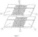
- FIG. 7illustrates magnetic structure that consists of multiple cells and windings connected in the same manner as described in the previous versions, where the number cells is n and there are n windings;
- FIG. 8shows another version of the invention which consists of multiple pads with inner cuts
- FIG. 9shows another version of the invention
- FIG. 10shows version of the invention that is a multi-cell linear pad
- FIG. 11illustrates shows another version of the invention
- FIG. 12illustrates another version of the invention
- FIG. 13shows another version of the invention
- FIG. 14illustrates another version of the invention
- FIG. 15provides another version of the invention.
- FIG. 16illustrates another version of the invention
- IPTInductive Power Transfer
- the wireless transformerMagnetic structures for the wireless transformer have been studied by John T. Boys and Grant A. Covic in [1].
- One structure typeis the flat power pad [ FIG. 1 ].
- the flat power padis composed by ferrite core and two parallel connected coils that are winded around the center post. The coils are situated in the extremities of the center post. Ferrite extensions called wings are assigned on the outer edges.
- FIG. 1is a top view of the magnetic structure that can be either the primary or the secondary side of the wireless transformer because the two parts have identical shape and size.
- FIG. 2A lateral view of the wireless transformer composed by two power pads is shown in FIG. 2
- the primary and secondary sideis separated by an air gap.
- the primary and secondaryare made out of magnetically permeable material.
- the goalis to send power as far as possible, through a bigger gap.
- FIG. 3is illustrated the equivalent circuit of the wireless transformer where are represented the magnetic reluctances of the magnetically permeable material and the air gap.
- the desired magnetic flux pathis the following: primary structure reluctance R 2 , R 3 , R 4 then through the air gap reluctance R 5 after that it's picked up by the secondary reluctance R 8 ,R 7 ,R 6 then through the air gap reluctance R 6 and back to the primary.
- the reluctance of the airis much higher compared to the one of the magnetically permeable material and is defined by
- gapl gap ⁇ gap ⁇ Area gap
- l gapthe gap length
- ⁇ gapthe permeability of the gap
- Area gapthe horizontal section area of the gap. The length of the gap is fixed and given by the nominal distance between the primary and secondary side.
- the only way to decrease the reluctance of the airis to increase the horizontal section area. This is achieved by making the lateral plates of the pads bigger. Though, the increase of the lateral plates makes their reluctance bigger, the magnetic flux would not flow through the whole plate and this is undesirable.
- One way to solve this problemis to split the reluctance of the ears to multiple cells, by adding more winded center rods. The structure created is called a multi-cell structure. This way the magnetic flux generated is spread through the whole area of the ear. As a result, the inductive coupling of the wireless transformer increases, hence the overall efficiency of the system is higher.
- the first version of the inventioncomprises a magnetically high-permeable material and four windings.
- the padis composed by two symmetrical parts that are separated by the air gap, the primary side on the bottom, and the secondary side on top of the primary.
- the primarycontains the lateral plates 9 and 10 , the center rods 5 , 6 and around them are located windings 1 and 2 .
- the secondarycontains the lateral plates 11 and 12 , the center rods 7 , 8 and around them are located windings 3 and 4 .
- Each sideis actually made of two cells with one winding each; as a result the structure presented is a two-cell derivation from the 1 cell structure presented earlier.
- the primary and secondary windingscan be connected either in 8 shape, series or parallel as long as the following condition is fulfilled: the currents 15 and 16 flowing through primary or secondary windings have the same direction as depicted in FIG. 4 , so that the generated magnetic flux through the rods 5 and 6 , 7 and 8 respectively would have the same direction.
- Another advantage of this structureis given by the elongated lateral plates and multiple windings and consist of the lower susceptibility to longitudinal misalignment.
- the second version of the inventionis derived from the first version and comprises one more cell in addition. This makes it a three cell magnetic structure.
- the padis composed by the plates 17 , 18 , 19 , 20 , connected by the center rods, the windings 21 and 22 connected in the same manner as described in the first version of the invention.
- the center rods 23 and 24accommodate the additional two windings.
- This versionis further improved compared to to the previous one. It creates even lower air gap reluctance. As a result, the inductive coupling of the wireless transformer is higher and the power is transferred more efficient.
- Another advantage of this structureis given by the elongated lateral plates and multiple windings and consist of the lower susceptibility to longitudinal misalignment.
- leakage fluxThe magnetic flux that is recirculated in the primary side of the transformer and do not energize the secondary side as desired is called leakage flux.
- One way to increase the magnetic coupling of the wireless transformeris to decrease the undesired leakage flux. This can be achieved by increasing the path length of the leakage flux.
- This version of the inventionis composed by the plates 25 , 26 , 27 , 28 which have been cut in the areas indicated by 29 , 30 , 31 , 31 , 32 .
- the cutsare performed in order to create a longer path for the leakage flux lines. This increases the magnetic coupling of the wireless transformer therefore the efficiency of the system is higher.
- Another advantage of this structureis given by the elongated lateral plates and multiple windings and consist of the lower susceptibility to longitudinal misalignment.
- This magnetic structureconsists of multiple cells and wdidings connected in the same manner as described in the previous versions. If the number of cells is n there are n windings as indicated in the FIG. 7 by 37 and 38 and the plates 33 , 34 , 35 , 36 are n times longer compared to a single cell structure. This decreases the reluctance of the air gap, as a result the inductive coupling of the wireless transformer increases and the efficiency of the system is higher.
- Another advantage of this structureis given by the elongated lateral plates and multiple windings and consist of the lower susceptibility to longitudinal misalignent.
- FIG. 8is shown another version of the invention which consists of multiple pads with inner cuts.
- the cutsare located in the inner areas of the plates 40 , 41 , 42 , 43 as indicated.
- the multiple windings 44 and 45spread the total flux in the whole magnetic material.
- the advantage of this structureis that the total reluctance of the leakage flux path is lower, leading to a better coupled wireless transformer. This increases the efficiency of the wireless power transfer. Besides this we find that the elongated lateral plates give lower susceptibility to longitudinal misalignment.
- FIG. 9Another version of the invention is depicted in FIG. 9 . It consist of multiple primary windings 50 , secondary windings 51 and lateral plates 46 , 47 , 48 , 49 .
- the particularity of the structureis represented by the lateral shape of the plates which is round in the areas indicated by 52 , 53 , 54 and 55 in FIG. 9 .
- This shapeincreases the area available for the mutual flux lines that are picked-up by the secondary side. As a result, the coupling between the primary and secondary side of the wireless transformer increases and the wireless power is transferred more efficient.
- Another advantage of this structureis less susceptible to longitudinal misalignment.
- FIG. 10Another version of the invention is the multi-cell linear pad shown in FIG. 10 .
- the magnetic structure illustrated in FIG. 10is composed by the primary side on the bottom and the secondary side on top.
- the primary and secondaryare identical in shape and size.
- Each one of themis made of magnetic material composed by lateral plates 51 , 52 , 53 , 54 , central plates 59 and 60 , center rods 55 , 56 , 57 , 58 displaced in two rows on which are winded the coils 61 , 62 , 63 , 64 .
- a magnetic fluxis created by the primary windings 61 and 62 .
- the desired path direction of the fluxis the following: from extremities of the primary 51 , 52 through the center rods 55 , 56 , through the central plate 59 , through the air gap, to the secondary central plate 60 , through the secondary center rods 57 , 58 , through the secondary lateral plates 53 , 54 , through the air gap, and back in the primary plates 51 and 52 .
- One advantage of this structure configurationis the enlarged center plates 59 , 60 area, and thus the reluctance of the air gap between the plates is lower. As a result, the coupling of the wireless power transformer is increased.
- Another advantage of this structureis given by the elongated lateral plates and multiple windings and consist of the lower susceptibility to longitudinal misalignment.
- FIG. 11is illustrated another version of the invention.
- the magnetic structureis composed by the primary side on the bottom and the secondary side on top.
- the primary and secondaryare identical in shape and size. Each one of them is made of magnetically permeable material.
- the magnetic material of the structureis composed by lateral plates 65 , 66 , 67 , 68 and C core rods 69 , 70 .
- Each of the primary and secondary cellcomprise a pair of windings as indicated by 71 , 72 , 73 , 74 .
- windingsare connected in 8-shape in such way that one “pushes” and the other “pulls” the magnetic flux.
- the magnetic flux generated by the windingshas the following desired path: from lateral plates 65 , to rods 69 through plates 66 , through the air gap, through plates 67 , through rod 70 then through plates 68 , through the air gap and back to plates 65 .
- the windingsare magnetically shielded under the lateral plates.
- the purpose of the shieldingis to minimize the AC losses in the winding. As a result, a higher efficiency of the wireless power transfer is achieved.
- Another advantage of this structureis given by the elongated lateral plates and multiple windings and consist of the lower susceptibility to longitudinal misalignment.
- FIG. 12Another version of the invention is shown by FIG. 12 .
- This structureis similar to the previous one, the difference lie in the cuts 137 , 138 performed on the lateral plates and C core rod.
- the structureis composed by the primary side on the bottom and secondary side on top.
- the primary sideincludes the lateral plates 75 , 76 , C shape rods 79 and the windings 81 and 82 .
- the secondary sideincludes lateral plates 77 , 78 , C shape rods 80 and the windings 83 and 84 .
- the desired flux pathis the same as in the previous version, as a result the windings is preferred to be connected in the same manner.
- One advantage of this structureis the increased reluctance of the path for the leakage flux lines. This increases the inductive coupling between the primary and the secondary therefore a higher wireless power transfer is achieved.
- Another advantage of this versionis that the AC losses in the windings are lower because they are shielded under the lateral plates.
- Another advantage of this structureis given by the elongated lateral plates and multiple windings and consist of the lower susceptibility to longitudinal misalignment.
- FIG. 13shows another version of the invention. It comprises the primary side on the bottom and secondary side on top each of them made of magnetically permeable material.
- the structureis composed by the lateral plates 85 , 86 , 87 , 88 , center rods 89 and 90 and the windings 91 and 92 .
- the windingscan be connected either in 8-shape, series or parallel in such way that the magnetic flux generated have the following preferred direction: from plate 85 through rods 89 to plate 86 , through air gap, through plate 87 , through rods 90 , through plate 88 , through the air gap and back to the plate 85 .
- This structureis similar to the Multi-cell C-shaped Pad, the difference lie in the shape of the rod that links the lateral plates. In this case the rod is rounded creating a shorter path for the magnetic flux which translates in lower reluctance. As a result the coupling of the wireless transformer is higher and this way the power is transferred more efficient.
- FIG. 14is illustrated another version of the invention. It comprises the primary side on the bottom and secondary side on top each of them made of magnetically permeable material.
- the structureis composed by the lateral plates 93 , 94 , 95 , 96 , center plates 97 , 98 , E-shape rods 99 , 100 and the windings 101 , 102 , 103 , 104 .
- Both primary and secondary windingsare split on the three posts of the E-shape rod.
- the winding polaritiesare set in such way that the generated magnetic flux is flowing from the lateral plates 93 , 94 , through rods 99 to center plate 103 in the primary side, and from center plate 104 through rods 100 to lateral plates 95 , 96 in the secondary side.
- This structureoffers is that minimizes the leakage flux between the lateral plates 93 , 94 and 95 , 96 respectively.
- windingsare magnetically shielded under the lateral plates.
- the purpose of the shieldingis to minimize the AC losses in the winding. As a result, a higher efficiency of the wireless power transfer is achieved.
- the magnetic structurecomprises of a primary and a secondary assemblies identical in shape and size, but also can be combined with all the magnetic structures described here, and as a result will become non symmetrical primaries and secondaries.
- the structurecan have also a C-shape connection rod between disks.
- the structureis made of magnetically permeable material composed by the disks 107 , 108 , 109 , 110 , 111 , 112 , 6 branches of 3 parallel rods 113 , 114 , 115 , 116 , 117 , 118 on which are located the windings 119 , 120 .
- the primary windingsare energized with 120 degree separation in phase as follows: At zero degree phase disks 107 and 110 will be the field return path and disks 108 , 111 , 109 , 112 will be the transmission path. The path of the magnetic field at zero phase will be: from disk 107 will split to rods 113 and rod 115 . From rod 113 will go to disk 108 , through the air gap, through disk 111 through rod 116 , through disk 110 , through the air gap and back to disk 107 . From rod 115 will go to disk 109 , through the air gap, through disk 112 , through rod 118 , through disk 110 , through the air gap and back to disk 107 .
- phase disk 108 and 111will be the field return path and disk 107 , 110 , 109 , 112 will be the field transmission path.
- phase disk 109 and 112will be the field return path and disk 107 , 110 , 108 , 111 will be the field transmission path.
- This tri-phase systemcreates a rotational magnetic field between all disks.
- FIG. 16is illustrated another version of the invention.
- the structureis made of magnetically permeable material and copper wire windings and is composed by the primary side on the bottom and the secondary side on top. Both sides comprise the disks 121 , 122 , 123 , 123 , 125 , 126 , 6 branches of 3 parallel rods 129 , 130 , 131 , 132 , 133 , 134 the center plates 127 , 128 , the windings 135 , 136 .
- the primary windingsare energized with 120 degree separation in phase as follows: At zero degree phase the magnetic field will travel from disk 121 through rods 129 , through center plate 127 , through rods 130 , through disk 122 , through the air gap, through disk 125 , through rods 133 , through center plate 128 , through rods 132 , through disk 124 , through the air gap, and back to the disk 121 .
- the magnetic field pathis: from disk 122 , through rods 130 , through center plate 127 , through rods 131 , through disk 123 , through the air gap, through disk 126 , through rods 134 , through center plate, through rods 133 , through disk 125 , through air gap and back to disk 122 .
- the pathrotates and is: from disk 123 , through rod 131 , through center plate 127 , through rods 129 , through disk 121 , through air gap, through disk 124 , through the rods 132 , through center plate 128 , through rods 134 , through disk 126 , through the air gap and back to disk 123 .
Landscapes
- Engineering & Computer Science (AREA)
- Power Engineering (AREA)
- Electric Propulsion And Braking For Vehicles (AREA)
- Coils Of Transformers For General Uses (AREA)
- Current-Collector Devices For Electrically Propelled Vehicles (AREA)
Abstract
Description
where lgapis the gap length, μgapis the permeability of the gap and Areagapis the horizontal section area of the gap. The length of the gap is fixed and given by the nominal distance between the primary and secondary side.
- [1] Budhia, M.; Boys, J.; Covic, G.; Huang, C. “Development of a single-sided flux magnetic coupler for electric vehicle IPT charging systems”, Industrial Electronics, IEEE Transactions on, Volume: PP, Issue: 99, Publication Year: 2011, Page(s): 1-1.
Claims (18)
Priority Applications (1)
| Application Number | Priority Date | Filing Date | Title |
|---|---|---|---|
| US13/887,350US10553351B2 (en) | 2012-05-04 | 2013-05-05 | Multiple cells magnetic structure for wireless power |
Applications Claiming Priority (2)
| Application Number | Priority Date | Filing Date | Title |
|---|---|---|---|
| US201261642785P | 2012-05-04 | 2012-05-04 | |
| US13/887,350US10553351B2 (en) | 2012-05-04 | 2013-05-05 | Multiple cells magnetic structure for wireless power |
Publications (2)
| Publication Number | Publication Date |
|---|---|
| US20130314200A1 US20130314200A1 (en) | 2013-11-28 |
| US10553351B2true US10553351B2 (en) | 2020-02-04 |
Family
ID=48470886
Family Applications (1)
| Application Number | Title | Priority Date | Filing Date |
|---|---|---|---|
| US13/887,350Active2035-07-05US10553351B2 (en) | 2012-05-04 | 2013-05-05 | Multiple cells magnetic structure for wireless power |
Country Status (2)
| Country | Link |
|---|---|
| US (1) | US10553351B2 (en) |
| EP (1) | EP2660834B1 (en) |
Cited By (2)
| Publication number | Priority date | Publication date | Assignee | Title |
|---|---|---|---|---|
| WO2024261116A1 (en)* | 2023-06-20 | 2024-12-26 | Magnetec Gmbh | Transmitting and/or receiving unit, charging device, energy transfer unit, motor vehicle, method for producing a transmitting and/or receiving unit, use of a metal glass material and use of magnetic-field-sensitive particles |
| USRE50259E1 (en)* | 2016-03-10 | 2025-01-07 | Wireless Advanced Vehicle Electrification, Llc | Bi-plane wireless power transmission pad |
Families Citing this family (4)
| Publication number | Priority date | Publication date | Assignee | Title |
|---|---|---|---|---|
| DE102013113244A1 (en)* | 2013-11-29 | 2015-06-03 | Paul Vahle Gmbh & Co. Kg | Coil for an inductive energy transfer system |
| DE102014225974A1 (en)* | 2014-12-16 | 2016-06-16 | Continental Automotive Gmbh | Vehicle inductive charging device for inductive charging of a vehicle, vehicle or stationary charging station |
| US10984946B2 (en) | 2016-12-20 | 2021-04-20 | Witricity Corporation | Reducing magnetic flux density proximate to a wireless charging pad |
| US10819156B2 (en) | 2017-12-05 | 2020-10-27 | Witricity Corporation | Flush-mount wireless charging power-transfer system |
Citations (48)
| Publication number | Priority date | Publication date | Assignee | Title |
|---|---|---|---|---|
| US1614161A (en)* | 1927-01-11 | Polyphase transformer | ||
| US1876451A (en) | 1932-09-06 | r gurtler | ||
| US2064773A (en)* | 1933-06-01 | 1936-12-15 | Ferrocart Corp Of America | Method for making magnetic cores |
| US3502966A (en)* | 1967-06-05 | 1970-03-24 | Maxim Izrailevich Perets | Transducer device for measuring the relative position of two relatively movable objects |
| US3668589A (en)* | 1970-12-08 | 1972-06-06 | Pioneer Magnetics Inc | Low frequency magnetic core inductor structure |
| US4030058A (en)* | 1976-03-30 | 1977-06-14 | Westinghouse Electric Corporation | Inductive coupler |
| US4301404A (en) | 1979-02-09 | 1981-11-17 | Solartron Electronic Group Limited | Methods and apparatus for analyzing periodic waveforms |
| US4447795A (en)* | 1981-05-05 | 1984-05-08 | The United States Of America As Represented By The United States Department Of Energy | Laminated grid and web magnetic cores |
| US4471271A (en)* | 1982-02-16 | 1984-09-11 | Rca Corporation | Self-regulating saturating core television receiver power supply |
| US4705975A (en)* | 1985-07-30 | 1987-11-10 | Voest-Alpine Automotive Gesselschaft | Synchro-generator |
| US4782582A (en)* | 1984-12-13 | 1988-11-08 | Eastrock Technology Inc. | Process for the manufacture of a toroidal ballast choke |
| FR2663452A3 (en)* | 1989-12-21 | 1991-12-20 | Tdk Corp | Thin ferrite core with three limbs for electronic devices |
| EP0507360A2 (en) | 1991-01-30 | 1992-10-07 | The Boeing Company | Current mode bus coupler with planar coils and shields |
| JPH09266121A (en)* | 1996-03-29 | 1997-10-07 | Matsushita Electric Ind Co Ltd | Non-contact power supply |
| US5767667A (en)* | 1995-03-03 | 1998-06-16 | Bell Technologies, Inc. | Magnetic core non-contact clamp-on current sensor |
| WO1999048130A1 (en) | 1998-03-14 | 1999-09-23 | Applied Materials, Inc. | Distributed inductively-coupled plasma source |
| EP1011187A1 (en) | 1998-12-10 | 2000-06-21 | Paul Vahle GmbH & Co. KG | Device for non-contact, inductive transmission of energy |
| WO2001016995A1 (en) | 1999-08-27 | 2001-03-08 | Illumagraphics, Llc | Induction electroluminescent lamp |
| JP2001076598A (en) | 1999-09-03 | 2001-03-23 | Omron Corp | Detecting coil and proximity switch using it |
| DE10112892A1 (en) | 2001-03-15 | 2002-10-10 | Vahle Paul Kg | Device for transferring data in system for contactless inductive energy transfer uses primary current conductor with inductive coupling in and out of data to transfer data in addition to energy |
| JP2004119748A (en)* | 2002-09-27 | 2004-04-15 | Aichi Electric Co Ltd | Iron core structure for contactless power supply apparatus |
| US20040085174A1 (en)* | 2002-11-01 | 2004-05-06 | Decristofaro Nicholas J. | Bulk laminated amorphous metal inductive device |
| US20040119576A1 (en) | 2001-02-14 | 2004-06-24 | Fumiaki Nakao | Noncontact coupler |
| US20040130426A1 (en)* | 2003-01-07 | 2004-07-08 | Minebea Co., Ltd. | Inverter transformer to light multiple lamps |
| US20040232845A1 (en) | 2003-02-04 | 2004-11-25 | Baarman David W. | Inductive coil assembly |
| US20050116683A1 (en)* | 2002-05-13 | 2005-06-02 | Splashpower Limited | Contact-less power transfer |
| US20050140482A1 (en) | 2002-05-13 | 2005-06-30 | Cheng Lily K. | Contact-less power transfer |
| EP1634366A1 (en) | 2003-05-23 | 2006-03-15 | Auckland Uniservices Limited | Frequency controlled resonant converter |
| US20080048814A1 (en)* | 2006-08-25 | 2008-02-28 | Robert Weger | High voltage transformer |
| WO2008140333A2 (en) | 2007-05-10 | 2008-11-20 | Auckland Uniservices Limited | Multi power sourced electric vehicle |
| JP2009123727A (en) | 2007-11-12 | 2009-06-04 | Ricoh Elemex Corp | Noncontact transmitter and core |
| WO2009111597A2 (en) | 2008-03-05 | 2009-09-11 | Nigel Power Llc | Packaging and details of a wireless power device |
| GB2458476A (en) | 2008-03-19 | 2009-09-23 | Rolls Royce Plc | Inductive electrical coupler for submerged power generation apparatus |
| US20090237197A1 (en)* | 2008-03-14 | 2009-09-24 | Alexandr Ikriannikov | Method For Making Magnetic Components With M-Phase Coupling, And Related Inductor Structures |
| EP2172952A1 (en) | 2007-06-20 | 2010-04-07 | Panasonic Electric Works Co., Ltd | Non-contact power transmitting device and method for fabricating its secondary side |
| EP2196351A1 (en) | 2007-10-25 | 2010-06-16 | Toyota Jidosha Kabushiki Kaisha | Electric vehicle and power feeding apparatus for the vehicle |
| US20100171580A1 (en)* | 2007-01-15 | 2010-07-08 | Toru Abe | Reactor core and reactor |
| US20100176908A1 (en)* | 2006-11-29 | 2010-07-15 | Ryutaro Mori | Coil device |
| WO2010090538A1 (en) | 2009-02-05 | 2010-08-12 | Auckland Uniservices Limited | Inductive power transfer apparatus |
| WO2010090539A1 (en) | 2009-02-05 | 2010-08-12 | Auckland Uniservices Limited | Inductive power transfer apparatus |
| US20100308939A1 (en) | 2008-09-27 | 2010-12-09 | Kurs Andre B | Integrated resonator-shield structures |
| US20110025445A1 (en)* | 2009-07-31 | 2011-02-03 | Delta Electronics, Inc. | Magnetic element module |
| JP2011142177A (en) | 2010-01-06 | 2011-07-21 | Kobe Steel Ltd | Contactless power transmission device, and coil unit for contactless power transmission device |
| WO2011148289A2 (en) | 2010-05-28 | 2011-12-01 | Koninklijke Philips Electronics N.V. | Transmitter module for use in a modular power transmitting system |
| WO2012008693A2 (en) | 2010-07-16 | 2012-01-19 | 주식회사 한림포스텍 | Core assembly for wireless power communication and power supply device for wireless power communication including same, and method for manufacturing a core assembly for wireless power communication |
| WO2012018268A1 (en) | 2010-08-05 | 2012-02-09 | Auckland Uniservices Limited | Inductive power transfer apparatus |
| US20120056706A1 (en)* | 2010-09-02 | 2012-03-08 | Abb Technology Ag | Wound transformer core with support structure |
| CN105186711A (en)* | 2015-09-06 | 2015-12-23 | 哈尔滨工业大学 | Bridge arm winding type flat plate magnetic core receiving end applied to wireless power supply of electric cars |
- 2013
- 2013-05-05USUS13/887,350patent/US10553351B2/enactiveActive
- 2013-05-06EPEP13405057.4Apatent/EP2660834B1/enactiveActive
Patent Citations (48)
| Publication number | Priority date | Publication date | Assignee | Title |
|---|---|---|---|---|
| US1614161A (en)* | 1927-01-11 | Polyphase transformer | ||
| US1876451A (en) | 1932-09-06 | r gurtler | ||
| US2064773A (en)* | 1933-06-01 | 1936-12-15 | Ferrocart Corp Of America | Method for making magnetic cores |
| US3502966A (en)* | 1967-06-05 | 1970-03-24 | Maxim Izrailevich Perets | Transducer device for measuring the relative position of two relatively movable objects |
| US3668589A (en)* | 1970-12-08 | 1972-06-06 | Pioneer Magnetics Inc | Low frequency magnetic core inductor structure |
| US4030058A (en)* | 1976-03-30 | 1977-06-14 | Westinghouse Electric Corporation | Inductive coupler |
| US4301404A (en) | 1979-02-09 | 1981-11-17 | Solartron Electronic Group Limited | Methods and apparatus for analyzing periodic waveforms |
| US4447795A (en)* | 1981-05-05 | 1984-05-08 | The United States Of America As Represented By The United States Department Of Energy | Laminated grid and web magnetic cores |
| US4471271A (en)* | 1982-02-16 | 1984-09-11 | Rca Corporation | Self-regulating saturating core television receiver power supply |
| US4782582A (en)* | 1984-12-13 | 1988-11-08 | Eastrock Technology Inc. | Process for the manufacture of a toroidal ballast choke |
| US4705975A (en)* | 1985-07-30 | 1987-11-10 | Voest-Alpine Automotive Gesselschaft | Synchro-generator |
| FR2663452A3 (en)* | 1989-12-21 | 1991-12-20 | Tdk Corp | Thin ferrite core with three limbs for electronic devices |
| EP0507360A2 (en) | 1991-01-30 | 1992-10-07 | The Boeing Company | Current mode bus coupler with planar coils and shields |
| US5767667A (en)* | 1995-03-03 | 1998-06-16 | Bell Technologies, Inc. | Magnetic core non-contact clamp-on current sensor |
| JPH09266121A (en)* | 1996-03-29 | 1997-10-07 | Matsushita Electric Ind Co Ltd | Non-contact power supply |
| WO1999048130A1 (en) | 1998-03-14 | 1999-09-23 | Applied Materials, Inc. | Distributed inductively-coupled plasma source |
| EP1011187A1 (en) | 1998-12-10 | 2000-06-21 | Paul Vahle GmbH & Co. KG | Device for non-contact, inductive transmission of energy |
| WO2001016995A1 (en) | 1999-08-27 | 2001-03-08 | Illumagraphics, Llc | Induction electroluminescent lamp |
| JP2001076598A (en) | 1999-09-03 | 2001-03-23 | Omron Corp | Detecting coil and proximity switch using it |
| US20040119576A1 (en) | 2001-02-14 | 2004-06-24 | Fumiaki Nakao | Noncontact coupler |
| DE10112892A1 (en) | 2001-03-15 | 2002-10-10 | Vahle Paul Kg | Device for transferring data in system for contactless inductive energy transfer uses primary current conductor with inductive coupling in and out of data to transfer data in addition to energy |
| US20050140482A1 (en) | 2002-05-13 | 2005-06-30 | Cheng Lily K. | Contact-less power transfer |
| US20050116683A1 (en)* | 2002-05-13 | 2005-06-02 | Splashpower Limited | Contact-less power transfer |
| JP2004119748A (en)* | 2002-09-27 | 2004-04-15 | Aichi Electric Co Ltd | Iron core structure for contactless power supply apparatus |
| US20040085174A1 (en)* | 2002-11-01 | 2004-05-06 | Decristofaro Nicholas J. | Bulk laminated amorphous metal inductive device |
| US20040130426A1 (en)* | 2003-01-07 | 2004-07-08 | Minebea Co., Ltd. | Inverter transformer to light multiple lamps |
| US20040232845A1 (en) | 2003-02-04 | 2004-11-25 | Baarman David W. | Inductive coil assembly |
| EP1634366A1 (en) | 2003-05-23 | 2006-03-15 | Auckland Uniservices Limited | Frequency controlled resonant converter |
| US20080048814A1 (en)* | 2006-08-25 | 2008-02-28 | Robert Weger | High voltage transformer |
| US20100176908A1 (en)* | 2006-11-29 | 2010-07-15 | Ryutaro Mori | Coil device |
| US20100171580A1 (en)* | 2007-01-15 | 2010-07-08 | Toru Abe | Reactor core and reactor |
| WO2008140333A2 (en) | 2007-05-10 | 2008-11-20 | Auckland Uniservices Limited | Multi power sourced electric vehicle |
| EP2172952A1 (en) | 2007-06-20 | 2010-04-07 | Panasonic Electric Works Co., Ltd | Non-contact power transmitting device and method for fabricating its secondary side |
| EP2196351A1 (en) | 2007-10-25 | 2010-06-16 | Toyota Jidosha Kabushiki Kaisha | Electric vehicle and power feeding apparatus for the vehicle |
| JP2009123727A (en) | 2007-11-12 | 2009-06-04 | Ricoh Elemex Corp | Noncontact transmitter and core |
| WO2009111597A2 (en) | 2008-03-05 | 2009-09-11 | Nigel Power Llc | Packaging and details of a wireless power device |
| US20090237197A1 (en)* | 2008-03-14 | 2009-09-24 | Alexandr Ikriannikov | Method For Making Magnetic Components With M-Phase Coupling, And Related Inductor Structures |
| GB2458476A (en) | 2008-03-19 | 2009-09-23 | Rolls Royce Plc | Inductive electrical coupler for submerged power generation apparatus |
| US20100308939A1 (en) | 2008-09-27 | 2010-12-09 | Kurs Andre B | Integrated resonator-shield structures |
| WO2010090538A1 (en) | 2009-02-05 | 2010-08-12 | Auckland Uniservices Limited | Inductive power transfer apparatus |
| WO2010090539A1 (en) | 2009-02-05 | 2010-08-12 | Auckland Uniservices Limited | Inductive power transfer apparatus |
| US20110025445A1 (en)* | 2009-07-31 | 2011-02-03 | Delta Electronics, Inc. | Magnetic element module |
| JP2011142177A (en) | 2010-01-06 | 2011-07-21 | Kobe Steel Ltd | Contactless power transmission device, and coil unit for contactless power transmission device |
| WO2011148289A2 (en) | 2010-05-28 | 2011-12-01 | Koninklijke Philips Electronics N.V. | Transmitter module for use in a modular power transmitting system |
| WO2012008693A2 (en) | 2010-07-16 | 2012-01-19 | 주식회사 한림포스텍 | Core assembly for wireless power communication and power supply device for wireless power communication including same, and method for manufacturing a core assembly for wireless power communication |
| WO2012018268A1 (en) | 2010-08-05 | 2012-02-09 | Auckland Uniservices Limited | Inductive power transfer apparatus |
| US20120056706A1 (en)* | 2010-09-02 | 2012-03-08 | Abb Technology Ag | Wound transformer core with support structure |
| CN105186711A (en)* | 2015-09-06 | 2015-12-23 | 哈尔滨工业大学 | Bridge arm winding type flat plate magnetic core receiving end applied to wireless power supply of electric cars |
Non-Patent Citations (2)
| Title |
|---|
| European Patent Office Search Report, dated Jan. 13, 2014, Application No. EP 13405057.4. |
| Masato Chigira et al: "Small-size light-weight transformer with new core structure for contactless electric vehicle power transfer system", Energy Conversion Congress and Exposition (ECCE), 2011 IEEE, IEEE, Sep. 17, 2011, pp. 260-266. |
Cited By (2)
| Publication number | Priority date | Publication date | Assignee | Title |
|---|---|---|---|---|
| USRE50259E1 (en)* | 2016-03-10 | 2025-01-07 | Wireless Advanced Vehicle Electrification, Llc | Bi-plane wireless power transmission pad |
| WO2024261116A1 (en)* | 2023-06-20 | 2024-12-26 | Magnetec Gmbh | Transmitting and/or receiving unit, charging device, energy transfer unit, motor vehicle, method for producing a transmitting and/or receiving unit, use of a metal glass material and use of magnetic-field-sensitive particles |
Also Published As
| Publication number | Publication date |
|---|---|
| US20130314200A1 (en) | 2013-11-28 |
| EP2660834B1 (en) | 2015-10-28 |
| EP2660834A3 (en) | 2014-02-12 |
| EP2660834A2 (en) | 2013-11-06 |
Similar Documents
| Publication | Publication Date | Title |
|---|---|---|
| US10553351B2 (en) | Multiple cells magnetic structure for wireless power | |
| US10083791B2 (en) | Integrated magnetics for soft switching converter | |
| US10033178B2 (en) | Linear electromagnetic device | |
| US9412510B2 (en) | Three-phase reactor | |
| EP2873078B1 (en) | Hybrid transformer cores | |
| CN105895328B (en) | Three-phase five-limb iron core and stationary electromagnetic equipment | |
| US20180061557A1 (en) | Resonant high current density transformer with improved structure | |
| US8872614B2 (en) | Transformer | |
| US20210327629A1 (en) | Common mode choke coil | |
| US9123461B2 (en) | Reconfiguring tape wound cores for inductors | |
| US20230005653A1 (en) | High frequency integrated planar magnetics for a bidirectional ac to dc cllc resonant converter | |
| US9196417B2 (en) | Magnetic configuration for high efficiency power processing | |
| US11756726B2 (en) | Magnetic structures for large air gap | |
| CN113439315A (en) | Transformer device | |
| JP2020501365A (en) | Semi-hybrid transformer core | |
| JP5918020B2 (en) | Non-contact power supply coil | |
| JP5923908B2 (en) | Reactor | |
| KR101595774B1 (en) | Composite Coil Module for Transmitting Wireless Power | |
| CN106560902A (en) | Magnetic core of transformer, transformer, and wireless charging device of automobile | |
| CN206194492U (en) | Magnetic core of transformer , transformer and car wireless charging device | |
| US10840004B2 (en) | Reducing reluctance in magnetic devices | |
| CN221668643U (en) | Magnetically integrated inductor prepared using laminated strips | |
| CN119889887A (en) | Main transformer with synchronous integration of windings and magnetic core for inhibiting magnetic circuit cancellation | |
| CN118398357A (en) | High-frequency transformer based on non-cutting nanocrystalline and design method | |
| CN101447282B (en) | Butt three-phase five-limb amorphous core device with approximate-circle cross-section |
Legal Events
| Date | Code | Title | Description |
|---|---|---|---|
| AS | Assignment | Owner name:DET INTERNATIONAL HOLDING LIMITED, CAYMAN ISLANDS Free format text:ASSIGNMENT OF ASSIGNORS INTEREST;ASSIGNORS:JITARU, IONEL;DAVILA, MARCO ANTONIO;SAVU, ANDREI;AND OTHERS;SIGNING DATES FROM 20130808 TO 20130809;REEL/FRAME:030998/0794 | |
| STPP | Information on status: patent application and granting procedure in general | Free format text:RESPONSE TO NON-FINAL OFFICE ACTION ENTERED AND FORWARDED TO EXAMINER | |
| AS | Assignment | Owner name:DELTA ELECTRONICS (THAILAND) PUBLIC CO., LTD., THA Free format text:ASSIGNMENT OF ASSIGNORS INTEREST;ASSIGNOR:DET INTERNATIONAL HOLDING LIMITED;REEL/FRAME:048585/0574 Effective date:20190121 Owner name:DELTA ELECTRONICS (THAILAND) PUBLIC CO., LTD., THAILAND Free format text:ASSIGNMENT OF ASSIGNORS INTEREST;ASSIGNOR:DET INTERNATIONAL HOLDING LIMITED;REEL/FRAME:048585/0574 Effective date:20190121 | |
| STPP | Information on status: patent application and granting procedure in general | Free format text:NON FINAL ACTION MAILED | |
| STPP | Information on status: patent application and granting procedure in general | Free format text:NOTICE OF ALLOWANCE MAILED -- APPLICATION RECEIVED IN OFFICE OF PUBLICATIONS | |
| STPP | Information on status: patent application and granting procedure in general | Free format text:PUBLICATIONS -- ISSUE FEE PAYMENT VERIFIED | |
| STCF | Information on status: patent grant | Free format text:PATENTED CASE | |
| MAFP | Maintenance fee payment | Free format text:PAYMENT OF MAINTENANCE FEE, 4TH YEAR, LARGE ENTITY (ORIGINAL EVENT CODE: M1551); ENTITY STATUS OF PATENT OWNER: LARGE ENTITY Year of fee payment:4 |