US10552979B2 - Output of a neural network method for deep odometry assisted by static scene optical flow - Google Patents
Output of a neural network method for deep odometry assisted by static scene optical flowDownload PDFInfo
- Publication number
- US10552979B2 US10552979B2US15/703,885US201715703885AUS10552979B2US 10552979 B2US10552979 B2US 10552979B2US 201715703885 AUS201715703885 AUS 201715703885AUS 10552979 B2US10552979 B2US 10552979B2
- Authority
- US
- United States
- Prior art keywords
- pair
- cnn
- image
- generating
- dnn
- Prior art date
- Legal status (The legal status is an assumption and is not a legal conclusion. Google has not performed a legal analysis and makes no representation as to the accuracy of the status listed.)
- Active
Links
Images


Classifications
- G—PHYSICS
- G06—COMPUTING OR CALCULATING; COUNTING
- G06V—IMAGE OR VIDEO RECOGNITION OR UNDERSTANDING
- G06V10/00—Arrangements for image or video recognition or understanding
- G06V10/40—Extraction of image or video features
- G06V10/62—Extraction of image or video features relating to a temporal dimension, e.g. time-based feature extraction; Pattern tracking
- G—PHYSICS
- G05—CONTROLLING; REGULATING
- G05D—SYSTEMS FOR CONTROLLING OR REGULATING NON-ELECTRIC VARIABLES
- G05D1/00—Control of position, course, altitude or attitude of land, water, air or space vehicles, e.g. using automatic pilots
- G05D1/02—Control of position or course in two dimensions
- G05D1/021—Control of position or course in two dimensions specially adapted to land vehicles
- G05D1/0231—Control of position or course in two dimensions specially adapted to land vehicles using optical position detecting means
- G05D1/0246—Control of position or course in two dimensions specially adapted to land vehicles using optical position detecting means using a video camera in combination with image processing means
- G05D1/0253—Control of position or course in two dimensions specially adapted to land vehicles using optical position detecting means using a video camera in combination with image processing means extracting relative motion information from a plurality of images taken successively, e.g. visual odometry, optical flow
- G—PHYSICS
- G06—COMPUTING OR CALCULATING; COUNTING
- G06F—ELECTRIC DIGITAL DATA PROCESSING
- G06F18/00—Pattern recognition
- G06F18/20—Analysing
- G06F18/25—Fusion techniques
- G06F18/251—Fusion techniques of input or preprocessed data
- G06K9/3233—
- G—PHYSICS
- G06—COMPUTING OR CALCULATING; COUNTING
- G06T—IMAGE DATA PROCESSING OR GENERATION, IN GENERAL
- G06T7/00—Image analysis
- G06T7/20—Analysis of motion
- G06T7/269—Analysis of motion using gradient-based methods
- G—PHYSICS
- G06—COMPUTING OR CALCULATING; COUNTING
- G06T—IMAGE DATA PROCESSING OR GENERATION, IN GENERAL
- G06T7/00—Image analysis
- G06T7/50—Depth or shape recovery
- G06T7/55—Depth or shape recovery from multiple images
- G—PHYSICS
- G06—COMPUTING OR CALCULATING; COUNTING
- G06T—IMAGE DATA PROCESSING OR GENERATION, IN GENERAL
- G06T7/00—Image analysis
- G06T7/70—Determining position or orientation of objects or cameras
- G06T7/73—Determining position or orientation of objects or cameras using feature-based methods
- G06T7/74—Determining position or orientation of objects or cameras using feature-based methods involving reference images or patches
- G—PHYSICS
- G06—COMPUTING OR CALCULATING; COUNTING
- G06V—IMAGE OR VIDEO RECOGNITION OR UNDERSTANDING
- G06V10/00—Arrangements for image or video recognition or understanding
- G06V10/70—Arrangements for image or video recognition or understanding using pattern recognition or machine learning
- G06V10/77—Processing image or video features in feature spaces; using data integration or data reduction, e.g. principal component analysis [PCA] or independent component analysis [ICA] or self-organising maps [SOM]; Blind source separation
- G06V10/80—Fusion, i.e. combining data from various sources at the sensor level, preprocessing level, feature extraction level or classification level
- G06V10/803—Fusion, i.e. combining data from various sources at the sensor level, preprocessing level, feature extraction level or classification level of input or preprocessed data
- G—PHYSICS
- G06—COMPUTING OR CALCULATING; COUNTING
- G06V—IMAGE OR VIDEO RECOGNITION OR UNDERSTANDING
- G06V10/00—Arrangements for image or video recognition or understanding
- G06V10/70—Arrangements for image or video recognition or understanding using pattern recognition or machine learning
- G06V10/82—Arrangements for image or video recognition or understanding using pattern recognition or machine learning using neural networks
- G—PHYSICS
- G06—COMPUTING OR CALCULATING; COUNTING
- G06V—IMAGE OR VIDEO RECOGNITION OR UNDERSTANDING
- G06V20/00—Scenes; Scene-specific elements
- G06V20/50—Context or environment of the image
- G06V20/56—Context or environment of the image exterior to a vehicle by using sensors mounted on the vehicle
- G06K2209/401—
- G—PHYSICS
- G06—COMPUTING OR CALCULATING; COUNTING
- G06T—IMAGE DATA PROCESSING OR GENERATION, IN GENERAL
- G06T2207/00—Indexing scheme for image analysis or image enhancement
- G06T2207/10—Image acquisition modality
- G06T2207/10016—Video; Image sequence
- G—PHYSICS
- G06—COMPUTING OR CALCULATING; COUNTING
- G06T—IMAGE DATA PROCESSING OR GENERATION, IN GENERAL
- G06T2207/00—Indexing scheme for image analysis or image enhancement
- G06T2207/10—Image acquisition modality
- G06T2207/10016—Video; Image sequence
- G06T2207/10021—Stereoscopic video; Stereoscopic image sequence
- G—PHYSICS
- G06—COMPUTING OR CALCULATING; COUNTING
- G06T—IMAGE DATA PROCESSING OR GENERATION, IN GENERAL
- G06T2207/00—Indexing scheme for image analysis or image enhancement
- G06T2207/10—Image acquisition modality
- G06T2207/10024—Color image
- G—PHYSICS
- G06—COMPUTING OR CALCULATING; COUNTING
- G06T—IMAGE DATA PROCESSING OR GENERATION, IN GENERAL
- G06T2207/00—Indexing scheme for image analysis or image enhancement
- G06T2207/10—Image acquisition modality
- G06T2207/10028—Range image; Depth image; 3D point clouds
- G—PHYSICS
- G06—COMPUTING OR CALCULATING; COUNTING
- G06T—IMAGE DATA PROCESSING OR GENERATION, IN GENERAL
- G06T2207/00—Indexing scheme for image analysis or image enhancement
- G06T2207/20—Special algorithmic details
- G06T2207/20081—Training; Learning
- G—PHYSICS
- G06—COMPUTING OR CALCULATING; COUNTING
- G06T—IMAGE DATA PROCESSING OR GENERATION, IN GENERAL
- G06T2207/00—Indexing scheme for image analysis or image enhancement
- G06T2207/20—Special algorithmic details
- G06T2207/20084—Artificial neural networks [ANN]
- G—PHYSICS
- G06—COMPUTING OR CALCULATING; COUNTING
- G06T—IMAGE DATA PROCESSING OR GENERATION, IN GENERAL
- G06T2207/00—Indexing scheme for image analysis or image enhancement
- G06T2207/30—Subject of image; Context of image processing
- G06T2207/30248—Vehicle exterior or interior
- G—PHYSICS
- G06—COMPUTING OR CALCULATING; COUNTING
- G06T—IMAGE DATA PROCESSING OR GENERATION, IN GENERAL
- G06T2207/00—Indexing scheme for image analysis or image enhancement
- G06T2207/30—Subject of image; Context of image processing
- G06T2207/30248—Vehicle exterior or interior
- G06T2207/30252—Vehicle exterior; Vicinity of vehicle
- G—PHYSICS
- G06—COMPUTING OR CALCULATING; COUNTING
- G06V—IMAGE OR VIDEO RECOGNITION OR UNDERSTANDING
- G06V2201/00—Indexing scheme relating to image or video recognition or understanding
- G06V2201/12—Acquisition of 3D measurements of objects
- G06V2201/121—Acquisition of 3D measurements of objects using special illumination
Definitions
- the field of the disclosureis in general related to autonomous vehicles and, in particular, to a method and system for deep odometry assisted by static scene optical flow.
- Embodiments of the present disclosureprovide a method of visual odometry for a non-transitory computer readable storage medium storing one or more programs.
- the one or more programsincludes instructions, which when executed by a computing device, causes the computing device to perform the following steps comprising: performing data alignment among sensors including a LiDAR, cameras and an IMU-GPS module; collecting image data and generating point clouds; processing a pair of consecutive images in the image data to recognize pixels corresponding to a same point in the point clouds; and establishing an optical flow for visual odometry.
- the methodfurther includes: receiving a first image of a first pair of image frames, and extracting representative features from the first image of the first pair in a first convolution neural network (CNN); and receiving a second image of the first pair, and extracting representative features from the second image of the first pair in the first CNN.
- CNNconvolution neural network
- the methodfurther includes: merging, in the first merge module, outputs from the first CNN; and decreasing feature map size in a second CNN.
- the methodfurther includes: generating a first flow output for each layer in a first deconvolution neural network (DNN).
- DNNdeconvolution neural network
- the methodfurther includes: merging, in a second merge module, outputs from the second CNN and the first DNN, and generating a first motion estimate.
- the methodfurther includes: generating a second flow output for each layer in a second DNN, the second flow output serves as a first optical flow prediction.
- the methodfurther includes: in response to the first motion estimate, generating a first set of motion parameters associated with the first pair in a recurrent neural network (RNN).
- RNNrecurrent neural network
- the methodfurther includes: training the visual odometry model by using at least one of the first optical flow prediction and the first set of motion parameters.
- the methodfurther includes: receiving a first image of a second pair of image frames, and extracting representative features from the first image of the second pair in the first CNN; and receiving a second image of the second pair, and extracting representative features from the second image of the second pair in the first CNN.
- the methodfurther includes: merging, in the first merge module, outputs from the first CNN; and decreasing feature map size in the second CNN.
- the methodfurther includes: generating a first flow output for each layer in the first DNN.
- the methodfurther includes: merging, in the second merge module, outputs from the second CNN and the first DNN, and generating a second motion estimate.
- the methodfurther includes: generating a second flow output for each layer in the second DNN, the second flow output serves as a second optical flow prediction.
- the methodfurther includes: in response to the second motion estimate and the first set of motion parameters, generating a second set of motion parameters associated with the second pair in the RNN.
- the methodfurther includes: training the visual odometry model by using at least one of the second optical flow prediction and the second set of motion parameters.
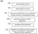
- FIG. 1is a flow diagram showing a method of visual odometry, in accordance with an embodiment
- FIG. 2is a block diagram of a system for visual odometry, in accordance with an embodiment
- FIG. 3Ais a block diagram showing the system illustrated in FIG. 2 in more detail
- FIG. 3Bis a schematic block diagram showing operation of the system illustrated in FIG. 3A ;
- FIG. 4is a flow diagram showing a method for visual odometry, in accordance with still another embodiment
- FIG. 5is a flow diagram showing a method for visual odometry, in accordance with yet another embodiment
- FIG. 6is a flow diagram showing a method of visual odometry, in accordance with yet still another embodiment
- FIG. 7is a flow diagram showing a method of visual odometry, in accordance with a further embodiment
- FIGS. 8A and 8Bare flow diagrams showing a method of visual odometry, in accordance with a still further embodiment.
- FIG. 9is a block diagram of a system for generating a ground truth dataset for motion planning, in accordance with some embodiments.
- wirelessrefers to wireless communication to a device or between multiple devices.
- Wireless devicesmay be anchored to a location and/or hardwired to a power system, depending on the needs of the business, venue, event or museum.
- wireless devicesmay be enabled to connect to Internet, but do not need to transfer data to and from Internet in order to communicate within the wireless information communication and delivery system.
- Smart Phoneor “smart phone” or “mobile device(s)” or “cellular phone” or “cellular” or “mobile phone” or the like refers to a wireless communication device, that includes, but not is limited to, an integrated circuit (IC), chip set, chip, system-on-a-chip including low noise amplifier, power amplifier, Application Specific Integrated Circuit (ASIC), digital integrated circuits, a transceiver, receiver, or transmitter, dynamic, static or non-transitory memory device(s), one or more computer processor(s) to process received and transmitted signals, for example, to and from the Internet, other wireless devices, and to provide communication within the wireless information communication and delivery system including send, broadcast, and receive information, signal data, location data, a bus line, an antenna to transmit and receive signals, and power supply such as a rechargeable battery or power storage unit.
- ICintegrated circuit
- ASICApplication Specific Integrated Circuit
- the chip or ICmay be constructed (“fabricated”) on a “die” cut from, for example, a Silicon, Sapphire, Indium Phosphide, or Gallium Arsenide wafer.
- the ICmay be, for example, analogue or digital on a chip or hybrid combination thereof.
- digital integrated circuitsmay contain anything from one to thousands or millions of signal invertors, and logic gates, e.g., “and”, “or”, “nand” and “nor gates”, flipflops, multiplexors, etc., on a square area that occupies only a few millimeters.
- the small size of, for instance, IC'sallows these circuits to provide high speed operation, low power dissipation, and reduced manufacturing cost compared with more complicated board-level integration.
- wirelesswireless data transfer
- wireless tracking and location systemwireless tracking system
- positioning systemwireless positioning system
- wireless positioning systemrefer without limitation to any wireless system that transfers data or communicates or broadcasts a message, which communication may include location coordinates or other information using one or more devices, e.g., wireless communication devices.
- modulerefers without limitation to any software, software program(s), firmware, or actual hardware or combination thereof that has been added on, downloaded, updated, transferred or originally part of a larger computation or transceiver system that assists in or provides computational ability including, but not limited to, logic functionality to assist in or provide communication broadcasts of commands or messages, which communication may include location coordinates or communications between, among, or to one or more devices, e.g., wireless communication devices.
- FIG. 1is a flow diagram showing a method 100 of visual odometry, in accordance with an embodiment.
- a non-transitory, i.e., non-volatile, computer readable storage mediumis provided.
- the non-transitory computer readable storage mediumis stored with one or more programs.
- the programis executed by the processing unit of a computing device, i.e., that are part of a vehicle, the computing device is caused to conduct specific operations set forth below in accordance with some embodiments of the present disclosure.
- non-transitory storage computer readable storage mediummay include magnetic hard discs, optical discs, floppy discs, flash memories, or forms of electrically programmable memories (EPROM) or electrically erasable and programmable (EEPROM) memories.
- EPROMelectrically programmable memories
- EEPROMelectrically erasable and programmable
- the term “non-transitory”may indicate that the storage medium is not embodied in a carrier wave or a propagated signal.
- a non-transitory storage mediummay store data that can, over time, change (e.g., in RAM or cache).
- a client applicationin operation, is transmitted to the computing device upon a request of a user, for example, by a smart phone 910 (see FIG. 9 ).
- the first client device 910may be a smart phone downloading the application from a computer server.
- the applicationis installed at the vehicle. Accordingly, specific functions may be executed by the user through a computing device, such as calibrating sensors and time synchronization, and, for example, sending and receiving calibration files for data alignment purposes.
- data alignmentwhich includes sensor calibration and time synchronization, is performed.
- a vehicleis equipped with multiple complementary sensors which require calibration in order to represent sensed information in a common coordinate system.
- sensors employed in the methodinclude a light detection and ranging (LiDAR) sensor, one or more cameras such as monocular cameras or stereo cameras, and an inertial navigation module.
- LiDAR sensor and the camerasare mounted on the roof of the vehicle.
- LiDAR sensorshave become increasingly common in both industrial and robotic applications. LIDAR sensors are particularly desirable for their direct distance measurements and high accuracy.
- the LIDAR sensoris equipped with many simultaneous rotating beams at varying angles, for example, a 64-beam rotating LiDAR.
- the multiple-beam LiDARprovides at least an order of magnitude more data than a single-beam LiDAR and enables new applications in mapping, object detection and recognition, scene understanding, and simultaneous localization and mapping (SLAM).
- the inertial navigation module in an embodiment according to the present disclosureincludes a global navigation satellite system (GNSS)-inertial measurement unit (IMU) module or an IMU-global positioning system (GPS) module.
- GNSSglobal navigation satellite system
- IMUIMU-inertial measurement unit
- GPSIMU-global positioning system
- the GNSS satellite signalsare used to correct or calibrate a solution from the IMU.
- the benefits of using GNSS with an IMUare that the IMU may be calibrated by the GNSS signals and that the IMU can provide position and angle updates at a quicker rate than GNSS.
- IMUfills in the gaps between GNSS positions. Additionally, GNSS may lose its signal and the IMU can continue to compute the position and angle during the period of lost GNSS signal.
- the two systemsare complementary and are often employed together.
- An integrated navigation systemconsisting of IMU and GPS is usually preferred due to the reduced dependency on GPS-only navigator in an area prone to poor signal reception or affected by multipath.
- the performance of the integrated systemlargely depends upon the quality of the IMU and the integration methodology. Considering the restricted use of high grade IMU and their associated price, low-cost IMUs are becoming the preferred choice for civilian navigation purposes. MEMS based inertial sensors have made possible the development of civilian land vehicle navigation as it offers small size and low-cost.
- the data alignment among the sensorsincludes calibrating intrinsic parameters of the camera, and calibrating extrinsic parameters between the camera and the inertial navigation module.
- transformation between the inertial navigation module and LiDAR coordinatemay be achieved by a method similar to that described in “ Unsupervised Calibration for Multi - beam Lasers ” by Levinson, Jesse and Sebastian Thrun, Experimental Robotics , Springer Berlin Heidelberg, 2014. Modifications made in the method 100 include, for example, the intrinsic parameters of each beam are calibrated in advance using a supervised method.
- LiDAR scansare collected in the form of sweep. A sweep is defined as a scan coverage of the LiDAR sensor rotating from 0 degree to 360 degrees.
- motion distortion within the sweepis corrected assuming that the angular and linear velocity of the LiDAR motion is constant.
- means for alleviating motion distortionis employed for points of LiDAR to ensure every point in the same sweep of LiDAR has an identical timestamp.
- LiDAR measurementsare recorded as the vehicle transitions through a series of known poses.
- Global pose informationis irrelevant, as there is no existing map, so only local pose information is required.
- Local pose datamay be acquired in any number of ways, e.g. from a wheel encoder and IMU, from an integrated GPS/IMU system, or from a GPS system with real-time corrections.
- transformation between the cameras and the LiDAR coordinatemay be calibrated using a method similar to that described in “Automatic Camera and Range Sensor Calibration Using a Single Shot” by Geiger, Andreas, et al., Robotics and Automation (ICRA), 2012 IEEE International Conference on. IEEE, 2012.
- Modifications made in the method 100include, for example, the intrinsic parameters of the cameras are calibrated in advance using a method described in “A Flexible New Technique for Camera Calibration” by Z. Zhang, IEEE Transactions on Pattern Analysis and Machine Intelligence, 22(11):1330-1334, 2000.
- the camerasinclude monocular cameras, which are calibrated by multiple shots instead of single shot.
- registrationis made by minimizing reprojection error and translation norm.
- time synchronization among the LiDAR sensor, cameras and inertial navigation moduleis achieved. Specifically, time synchronization between the LiDAR sensor and the inertial navigation module, between the inertial navigation module and the cameras, and between the LiDAR sensor and the cameras is achieved.
- a time triggeris used to synchronize the LiDAR and cameras to ensure data alignment.
- these sensorsare used to collect data in an environment.
- images of the environmentare captured by the cameras in approximately 30 Hz.
- LiDAR scansare collected in the form of a sweep in approximately 20 Hz.
- Vehicle poses, including position and orientation,are collected in an “east north up” (ENU) coordinate by the inertial navigation module in approximately 50 Hz.
- ENUeast north up
- machine learningis performed in a visual odometry model.
- Inputs to the visual odometry model for machine learninginclude images obtained by the cameras and point clouds obtained by the LiDAR.
- images obtained by the cameras and point clouds obtained by the LiDARIn an embodiment, for monocular cameras, consecutive RGB image frames in pairs are input. In another embodiment, for stereo cameras, RGB images with depth information (RGB-D) are input.
- CNNsconvolutional neural networks
- CNNshave become popular in many fields of computer vision. CNN has been widely applied to classification, and recently presented architectures also allow for per-pixel predictions like semantic segmentation or depth estimation from single images.
- a method of training CNNs end-to-end to learn predicting an optical flow field from a pair of imagesis disclosed.
- a prediction of static optical flow for a pair of input image framesis generated.
- a set of motion parameters for estimating a motion between the pair of input image framesis generated.
- the visual odometry modelis trained by using at least one of the prediction of static optical flow and the motion parameters.
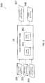
- FIG. 2is a block diagram of a system 200 for visual odometry, in accordance with an embodiment.
- the system 200includes a visual odometry model 24 .
- the visual odometry model 24includes one or more neural networks 241 and one or more merge modules 242 .
- the neural networksmay further include convolution neural networks (CNNs), deconvolution neural networks (DNNs) and a recurrent neural network (RNN).
- the merge modulesmay include merge layers in the neural networks.
- the visual odometry model 24receives images 201 from a camera and point clouds 202 from a LiDAR. Given vehicle poses 203 from an IMU-GPS module, the images 201 and the point clouds 202 are trained in the visual odometry model 24 .
- the images 201input in pair to the visual odometry model 24 , are matched against the point clouds 202 .
- the visual odometry model 24in response to the images 201 and point clouds 202 , generates a prediction of static optical flow 207 and a set of motion parameters 208 , which in turn may be used to train the visual odometry model 24 .
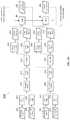
- FIG. 3Ais a block diagram showing the system 200 illustrated in FIG. 2 in more detail.
- the visual odometry model 24 in the system 200includes a first neural network 31 , a second neural network 35 and a third neural network 38 .
- the first neural network 31further includes a first CNN 311 , a second CNN 312 , and a first merge module 310 between the first CNN 311 and the second CNN 312 .
- the first CNN 311is configured to, in response to a pair of consecutive image frames 201 , extract representative features from the pair of consecutive image frames 201 .
- the first merge module 310is configured to merge the representative features.
- the representative featuresare merged by a patch-wise correlation, which is similar to that described in “Flownet: Learning Optical Flow with Convolutional Networks” by Fischer et.
- the representative featuresare merged by a simple concatenation.
- the second CNN 312then decreases the feature map size.
- An output of the second CNN 312constitutes a portion of a motion estimate 206 .
- the second neural network 35further includes a first DNN 351 , a second DNN 352 and a second merge module 350 .
- the first DNN 351is configured to, in response to an output from the second CNN 312 , generate a first flow output for each layer at a first resolution.
- the first flow outputwhich may have a relatively low resolution, constitutes another portion of the motion estimate 206 .
- the second merge module 350is configured to, in response to the output from the second CNN 312 and the first flow output from the first DNN 351 , merge these outputs by, for example, a patch-wise correlation or alternatively a simple concatenation as previously discussed, resulting in the motion estimate 206 .
- the second DNN 352is configured to, in response to the first flow output from the first DNN 351 , generate a first flow output for each layer at a second flow output for each layer at a second resolution.
- the second resolutionis higher than the first resolution.
- the second flow outputwhich may have a relatively high resolution, serves as a static scene optical flow.
- the third neural network 38includes an RNN.
- RNNrefers to a general type of neural network where the layers operate not only on the input data but also on delayed versions of hidden layers and/or output. In this manner, RNN has an internal state which it can use as a “memory” to keep track of past inputs and its corresponding decisions.
- the third neural network 38includes a Long Short-Term Memory (LSTM) architecture.
- the LSTM architectureis employed to allow RNN to learn longer-term trends. This is accomplished through the inclusion of gating cells which allow the neural network to selectively store and “forget” memories.
- the third neural network 38is configured to, in response to the motion estimate 206 from the second merge module 350 and a set of motion parameters associated with an immediately previous pair of consecutive image frames (shown in FIG. 3B ), generate a set of motion parameters 208 for the current pair of image frames 201 .
- FIG. 3Bis a schematic block diagram showing operation of the system 200 illustrated in FIG. 3A .
- the first CNN 311receives a first image 211 of a first pair of consecutive image frames 201 at time t 1 , and extracts representative features from the first image 211 of the first pair 201 . Subsequently, the first CNN 311 receives a second image 212 of the first pair 201 at time t 2 , and extracts representative features from the second image 212 of the first pair 201 . The extracted representative features are merged by the first merge module 310 and the merged features are reduced in feature map size by the second CNN 312 . Next, the first DNN 351 generates a low-resolution flow output based on the output of the second CNN 312 .
- the second merge module 350generates a first motion estimate 261 by merging the output of the second CNN 312 and the low-resolution flow output of the first DNN 351 .
- the second DNN 352generates a first static scene optical flow 271 based on the low-resolution flow output of the first DNN 351 .
- the RNN 38generates a first set of motion parameters 281 based on the first motion estimate 261 and a set of motion parameters associated with an immediately previous pair of consecutive image frames.
- the first CNN 311receives a first image 251 of a second pair of consecutive image frames at the time t 2 , and extracts representative features from the first image 251 of the second pair. Subsequently, the first CNN 311 receives a second image 252 of the second pair at time t 3 , and extracts representative features from the second image 252 of the second pair. The extracted representative features are merged by the first merge module 310 and the merged features are reduced in feature map size by the second CNN 312 . Next, the first DNN 351 generates a low-resolution flow output based on the output of the second CNN 312 .
- the second merge module 350generates a second motion estimate 262 by merging the output of the second CNN 312 and the low-resolution flow output of the first DNN 351 .
- the second DNN 352generates a second static scene optical flow 272 based on the low-resolution flow output of the first DNN 351 .
- the RNN 38generates a second set of motion parameters 282 based on the second motion estimate 262 and a set of motion parameters 281 associated with the first pair of consecutive image frames 201 .
- hand-crafted featuresare employed to extract keypoints and descriptors, and find matching points to solve motion parameters. Such feature-based approaches may fail when the scene has no salient keypoints.
- an end-to-end trained deep networkis employed for estimating motion parameters. Sequence learning sub-network can eliminate accumulated errors. Flow is used to enhance motion estimation because motion has a strong connection with flow.
- the method according to the present disclosureallows the visual odometry model to have higher generalization ability. Since the whole network is end-to-end trained, no hand-crafted features are required. The network suits well for new scenarios or scenes, while feature-based methods fail in new scenarios and redesign of features costs a lot of efforts and time.
- the deep networkis well suited to large amount of data because the model capacity and totally learned model can handle big data well. Since the price of GPS devices goes down, GPS signals can be added to the deep network. Also, other signals can be added into the model.
- the present disclosureproposes a flow prediction for predicting motion, and employs flow as additional information to enhance motion estimation.
- the designed structurecan easily fuse additional signals, such as GPS signals.
- FIG. 4is a flow diagram showing a method 400 for visual odometry, in accordance with still another embodiment.
- data alignment among sensors including a LiDAR, cameras and an inertia navigation module such as an IMU-GPS moduleis performed.
- image dataare obtained from the camera and point clouds are obtained from the LiDAR.
- a pair of consecutive images in the image datais processed to recognize pixels corresponding to a same point in the point clouds.
- the IMU-GPS moduleis learning to establish an optical flow every time it processes image data and generates a more precise optical flow. Consequently, with sufficient training, the IMU-GPS module is able to generate precise optical flows reflecting movement of a vehicle.
- FIG. 5is a flow diagram showing a method 500 for visual odometry, in accordance with yet another embodiment.
- CNNconvolution neural network
- outputs from the first CNNare merged in a first merge module.
- the outputsinclude the representative features of a first image of the pair and the representative features of a second image of the pair.
- the mergemay be achieved by a patch-wise correlation or a simple concatenation.
- the merged featuresare reduced in feature map size in a second CNN.
- the output of the second CNNconstitutes a portion of a motion estimate.
- a first flow output for each layeris generated in a first deconvolution neural network (DNN) at a first resolution.
- the first flow outputhas a relatively low resolution.
- the first flow outputconstitutes another portion of the motion estimate.
- outputs from the second CNN and the first DNNare merged in a second merge module, resulting in a motion estimate.
- a second flow output for each layeris generated in a second DNN at a second resolution higher than the first resolution.
- the second flow outputhas a relatively high resolution and serves as a static scene optical flow.
- accumulated errorsare reduced in a recurrent neural network (RNN).
- RNNrecurrent neural network
- sequence learning and predictiongenerates a set of motion parameters for estimating motion between the pair of consecutive input images.
- FIG. 6is a flow diagram showing a method 600 of visual odometry, in accordance with yet still another embodiment.
- outputs from the first CNNare merged in a first merge module.
- merged featuresare reduced in feature map size in a second CNN.
- a first flow output for each layeris generated in a first deconvolution neural network (DNN).
- DNNfirst deconvolution neural network
- outputs from the second CNN and the first DNNare then merged in a second merge module.
- a second flow output for each layeris generated in a second DNN.
- the second flow outputserves as an optical flow prediction.
- a set of motion parameters associated with the first pairis generated in a recurrent neural network (RNN) in response to the motion estimate from the second merge module and a set of motion parameters associated with an immediately previous pair of input images.
- RNNrecurrent neural network
- the visual odometry modelis trained by using at least one of the optical flow prediction and the set of motion parameters.
- operation 620it is determined if the visual odometry model is sufficiently trained. If affirmative, in operation 622 , the trained visual odometry model may enter a test mode. If not, then in operation 624 , another pair of consecutive image frames is received. Moreover, in operation 626 , the first set of motion parameters is provided to the RNN.
- FIG. 7is a flow diagram showing a method 700 of visual odometry, in accordance with a further embodiment.
- a prediction of static scene optical flow for each pair of the imagesis generated in a visual odometry model through deep learning.
- a set of motion parameters for each pair of the imagesis generated in the visual odometry model.
- the visual odometry modelis trained by using the prediction of static scene optical flow and the motion parameters.
- motion between a pair of consecutive image framesis predicted by the trained visual odometry model.
- FIGS. 8A and 8Bare flow diagrams showing a method 800 of visual odometry, in accordance with a still further embodiment.
- a first image of a first pair of image framesis received, and representative features are extracted from the first image of the first pair in a first convolution neural network (CNN).
- CNNconvolution neural network
- a second image of the first pairis received, and representative features are extracted from the second image of the first pair in the first CNN.
- outputs from the first CNNare merged in the first merge module.
- the merged featuresare decreased in feature map size in a second CNN.
- a first flow output for each layeris generated in a first deconvolution neural network (DNN).
- DNNfirst deconvolution neural network
- outputs from the second CNN and the first DNNare merged in a second merge module, resulting in a first motion estimate.
- a second flow output for each layeris generated in a second DNN.
- the second flow outputserves as a first optical flow prediction.
- a first set of motion parameters associated with the first pairis generated in a recurrent neural network (RNN).
- RNNrecurrent neural network
- the visual odometry modelis trained by using at least one of the first optical flow prediction and the first set of motion parameters.
- a first image of a second pair of image framesis received, and representative features are extracted from the first image of the second pair in the first CNN.
- a second image of the second pairis received, and representative features are extracted from the second image of the second pair in the first CNN.
- outputs from the first CNNare merged in the first merge module.
- the merged featuresare decreased in feature map size in the second CNN.
- a first flow output for each layeris generated in the first DNN.
- outputs from the second CNN and the first DNNare merged in the second merge module, resulting in a second motion estimate.
- a second flow output for each layeris generated in the second DNN.
- the second flow outputserves as a second optical flow prediction.
- a second set of motion parameters associated with the second pairis generated in the RNN.
- the visual odometry modelis trained by using at least one of the second optical flow prediction and the second set of motion parameters.
- FIG. 9is a block diagram of a system 900 for generating a ground truth dataset for motion planning, in accordance with some embodiments.
- the system 900includes a processor 901 , an computer server 902 , a network interface 903 , an input and output (I/O) device 905 , a storage device 907 , a memory 909 , and a bus or network 908 .
- the bus 908couples the network interface 903 , the I/O device 905 , the storage device 907 and the memory 909 to the processor 901 .
- the processor 901is configured to enable the computer server 902 , e.g., Internet server, to perform specific operations disclosed herein. It is to be noted that the operations and techniques described herein may be implemented, at least in part, in hardware, software, firmware, or any combination thereof. For example, various aspects of the described embodiments, e.g., the processor 901 , the computer server 902 , or the like, may be implemented within one or more processing units, including one or more microprocessing units, digital signal processing units (DSPs), application specific integrated circuits (ASICs), field programmable gate arrays (FPGAs), or any other equivalent integrated or discrete logic circuitry, as well as any combinations of such components.
- DSPsdigital signal processing units
- ASICsapplication specific integrated circuits
- FPGAsfield programmable gate arrays
- processing unitor “processing circuitry” may generally refer to any of the foregoing logic circuitry, alone or in combination with other logic circuitry, or any other equivalent circuitry.
- a control unit including hardwaremay also perform one or more of the techniques of the present disclosure.
- the computer server 902is configured to utilize the I/O port 905 communicate with external devices via a network 908 , such as a wireless network.
- a network 908such as a wireless network.
- the I/O port 905is a network interface component, such as an Ethernet card, an optical transceiver, a radio frequency transceiver, or any other type of device that can send and receive data from the Internet. Examples of network interfaces may include Bluetooth®, 3G and WiFi® radios in mobile computing devices as well as USB. Examples of wireless networks may include WiFi®, Bluetooth®, and 3G.
- the internet server 902is configured to utilize the I/O port 905 to wirelessly communicate with a client device 910 , such as a mobile phone, a tablet PC, a portable laptop or any other computing device with internet connectivity. Accordingly, electrical signals are transmitted between the computer server 900 and the client device 910 .
- a client device 910such as a mobile phone, a tablet PC, a portable laptop or any other computing device with internet connectivity. Accordingly, electrical signals are transmitted between the computer server 900 and the client device 910 .
- the computer server 902is a virtual server capable of performing any function a regular server has.
- the computer server 900is another client device of the system 900 .
- there may not be a centralized host for the system 900and the client devices 910 in the system are configured to communicate with each other directly.
- such client devices 910communicate with each other on a peer-to-peer (P2P) basis.
- P2Ppeer-to-peer
- the processor 901is configured to execute program instructions that include a tool module configured to perform a method as described and illustrated with reference to FIGS. 1, 4 through 7, 8A and 8B .
- the tool moduleis configured to execute the operations including: performing data alignment among sensors including a LiDAR, cameras and an IMU-GPS module; collecting image data and generating point clouds; processing, in the IMU-GPS module, a pair of consecutive images in the image data to recognize pixels corresponding to a same point in the point clouds; and establishing an optical flow for visual odometry.
- the network interface 903is configured to access program instructions and data accessed by the program instructions stored remotely through a network (not shown).
- the I/O device 905includes an input device and an output device configured for enabling user interaction with the system 900 .
- the input devicecomprises, for example, a keyboard, a mouse, and other devices.
- the output devicecomprises, for example, a display, a printer, and other devices.
- the storage device 907is configured for storing program instructions and data accessed by the program instructions.
- the storage device 907comprises, for example, a magnetic disk and an optical disk.
- the memory 909is configured to store program instructions to be executed by the processor 901 and data accessed by the program instructions.
- the memory 909comprises a random access memory (RAM) and/or some other volatile storage device and/or read only memory (ROM) and/or some other non-volatile storage device including other programmable read only memory (PROM), erasable programmable read only memory (EPROM), electronically erasable programmable read only memory (EEPROM), flash memory, a hard disk, a solid state drive (SSD), a compact disc ROM (CD-ROM), a floppy disk, a cassette, magnetic media, optical media, or other computer readable media.
- the memory 909is incorporated into the processor 901 .
Landscapes
- Engineering & Computer Science (AREA)
- Theoretical Computer Science (AREA)
- Physics & Mathematics (AREA)
- Computer Vision & Pattern Recognition (AREA)
- General Physics & Mathematics (AREA)
- Multimedia (AREA)
- Evolutionary Computation (AREA)
- Artificial Intelligence (AREA)
- Medical Informatics (AREA)
- Databases & Information Systems (AREA)
- Computing Systems (AREA)
- General Health & Medical Sciences (AREA)
- Health & Medical Sciences (AREA)
- Software Systems (AREA)
- Data Mining & Analysis (AREA)
- Remote Sensing (AREA)
- Radar, Positioning & Navigation (AREA)
- Aviation & Aerospace Engineering (AREA)
- Automation & Control Theory (AREA)
- Electromagnetism (AREA)
- Life Sciences & Earth Sciences (AREA)
- Bioinformatics & Cheminformatics (AREA)
- Bioinformatics & Computational Biology (AREA)
- Evolutionary Biology (AREA)
- General Engineering & Computer Science (AREA)
- Image Analysis (AREA)
Abstract
Description
Claims (16)
Priority Applications (1)
| Application Number | Priority Date | Filing Date | Title |
|---|---|---|---|
| US15/703,885US10552979B2 (en) | 2017-09-13 | 2017-09-13 | Output of a neural network method for deep odometry assisted by static scene optical flow |
Applications Claiming Priority (1)
| Application Number | Priority Date | Filing Date | Title |
|---|---|---|---|
| US15/703,885US10552979B2 (en) | 2017-09-13 | 2017-09-13 | Output of a neural network method for deep odometry assisted by static scene optical flow |
Publications (2)
| Publication Number | Publication Date |
|---|---|
| US20190080470A1 US20190080470A1 (en) | 2019-03-14 |
| US10552979B2true US10552979B2 (en) | 2020-02-04 |
Family
ID=65631256
Family Applications (1)
| Application Number | Title | Priority Date | Filing Date |
|---|---|---|---|
| US15/703,885ActiveUS10552979B2 (en) | 2017-09-13 | 2017-09-13 | Output of a neural network method for deep odometry assisted by static scene optical flow |
Country Status (1)
| Country | Link |
|---|---|
| US (1) | US10552979B2 (en) |
Cited By (4)
| Publication number | Priority date | Publication date | Assignee | Title |
|---|---|---|---|---|
| US10989540B2 (en)* | 2017-09-29 | 2021-04-27 | Goertek Inc. | Binocular vision localization method, device and system |
| US11584377B2 (en)* | 2019-11-21 | 2023-02-21 | Gm Cruise Holdings Llc | Lidar based detection of road surface features |
| US11669980B2 (en) | 2021-07-23 | 2023-06-06 | Waymo Llc | Optical flow based motion detection |
| US12442928B2 (en) | 2020-12-14 | 2025-10-14 | Aptiv Technologies AG | System and method for mapping a vehicle environment |
Families Citing this family (19)
| Publication number | Priority date | Publication date | Assignee | Title |
|---|---|---|---|---|
| US10762635B2 (en) | 2017-06-14 | 2020-09-01 | Tusimple, Inc. | System and method for actively selecting and labeling images for semantic segmentation |
| US10671083B2 (en) | 2017-09-13 | 2020-06-02 | Tusimple, Inc. | Neural network architecture system for deep odometry assisted by static scene optical flow |
| CN107589552B (en) | 2017-10-17 | 2023-08-04 | 歌尔光学科技有限公司 | Optical module assembly equipment |
| US11199506B2 (en)* | 2018-02-21 | 2021-12-14 | Applied Materials Israel Ltd. | Generating a training set usable for examination of a semiconductor specimen |
| US20190061771A1 (en)* | 2018-10-29 | 2019-02-28 | GM Global Technology Operations LLC | Systems and methods for predicting sensor information |
| CN109975792B (en)* | 2019-04-24 | 2021-02-05 | 福州大学 | Method for correcting point cloud motion distortion of multi-line laser radar based on multi-sensor fusion |
| CN110288702B (en)* | 2019-06-28 | 2021-05-18 | 联想(北京)有限公司 | Data processing method and electronic equipment |
| US11321853B2 (en)* | 2019-08-08 | 2022-05-03 | Nec Corporation | Self-supervised visual odometry framework using long-term modeling and incremental learning |
| CN110472585B (en)* | 2019-08-16 | 2020-08-04 | 中南大学 | VI-S L AM closed-loop detection method based on inertial navigation attitude track information assistance |
| JP2021033063A (en)* | 2019-08-23 | 2021-03-01 | 富士通株式会社 | Arithmetic processing device and method |
| CN112711249B (en) | 2019-10-24 | 2023-01-03 | 科沃斯商用机器人有限公司 | Robot positioning method and device, intelligent robot and storage medium |
| CN110956651B (en)* | 2019-12-16 | 2021-02-19 | 哈尔滨工业大学 | Terrain semantic perception method based on fusion of vision and vibrotactile sense |
| CN111353509B (en)* | 2020-03-31 | 2022-08-16 | 广西大学 | Key point extractor generation method of visual SLAM system |
| US11880997B2 (en) | 2020-08-28 | 2024-01-23 | Samsung Electronics Co., Ltd. | Method and apparatus with pose estimation |
| CN112171668A (en)* | 2020-09-21 | 2021-01-05 | 河南颂达信息技术有限公司 | Rail-mounted robot anti-jamming detection method and device based on artificial intelligence |
| US12014574B2 (en)* | 2020-10-26 | 2024-06-18 | The Boeing Company | Human gesture recognition for autonomous aircraft operation |
| US12315187B2 (en) | 2021-09-24 | 2025-05-27 | Volkswagen Group of America Investments, LLC | Heterogeneous multi-threaded visual odometry in autonomous driving |
| US12062202B2 (en) | 2021-09-24 | 2024-08-13 | Argo AI, LLC | Visual localization against a prior map |
| CN118521653B (en)* | 2024-07-23 | 2024-10-29 | 杭州智元研究院有限公司 | Positioning and mapping method and system based on fusion of LiDAR and inertial measurement in complex scenes |
Citations (179)
| Publication number | Priority date | Publication date | Assignee | Title |
|---|---|---|---|---|
| EP0299365A1 (en) | 1987-07-09 | 1989-01-18 | Cyclean, Inc | Matched absorptive end choke for microwave applicators |
| US6535114B1 (en) | 2000-03-22 | 2003-03-18 | Toyota Jidosha Kabushiki Kaisha | Method and apparatus for environment recognition |
| US6777904B1 (en) | 2003-02-25 | 2004-08-17 | Ford Global Technologies, Llc | Method and system for controlling a motor |
| US20040239756A1 (en) | 2003-05-30 | 2004-12-02 | Aliaga Daniel G. | Method and apparatus for computing error-bounded position and orientation of panoramic cameras in real-world environments |
| WO2005098739A1 (en) | 2004-04-08 | 2005-10-20 | Mobileye Technologies Limited | Pedestrian detection |
| WO2005098751A1 (en) | 2004-04-08 | 2005-10-20 | Mobileye Technologies Limited | Crowd detection |
| WO2005098782A1 (en) | 2004-04-08 | 2005-10-20 | Mobileye Technologies Limited | Collision warning system |
| US6975923B2 (en) | 2002-10-01 | 2005-12-13 | Roke Manor Research Limited | Autonomous vehicle guidance on or near airports |
| US20060188131A1 (en) | 2005-02-24 | 2006-08-24 | Xiang Zhang | System and method for camera tracking and pose estimation |
| US7103460B1 (en) | 1994-05-09 | 2006-09-05 | Automotive Technologies International, Inc. | System and method for vehicle diagnostics |
| US20070070069A1 (en)* | 2005-09-26 | 2007-03-29 | Supun Samarasekera | System and method for enhanced situation awareness and visualization of environments |
| US20080144925A1 (en)* | 2006-08-15 | 2008-06-19 | Zhiwei Zhu | Stereo-Based Visual Odometry Method and System |
| US20080249667A1 (en) | 2007-04-09 | 2008-10-09 | Microsoft Corporation | Learning and reasoning to enhance energy efficiency in transportation systems |
| US20090040054A1 (en) | 2007-04-11 | 2009-02-12 | Nec Laboratories America, Inc. | Real-time driving danger level prediction |
| US20090208106A1 (en) | 2008-02-15 | 2009-08-20 | Digitalsmiths Corporation | Systems and methods for semantically classifying shots in video |
| US20100049397A1 (en) | 2008-08-22 | 2010-02-25 | Garmin Ltd. | Fuel efficient routing |
| US20100067745A1 (en) | 2008-09-16 | 2010-03-18 | Ivan Kovtun | System and method for object clustering and identification in video |
| US7689559B2 (en) | 2006-02-08 | 2010-03-30 | Telenor Asa | Document similarity scoring and ranking method, device and computer program product |
| US7742841B2 (en) | 2005-02-23 | 2010-06-22 | Panasonic Electric Works Co., Ltd. | Autonomous vehicle and planar obstacle recognition method |
| US20100204964A1 (en)* | 2009-02-09 | 2010-08-12 | Utah State University | Lidar-assisted multi-image matching for 3-d model and sensor pose refinement |
| US7783403B2 (en) | 1994-05-23 | 2010-08-24 | Automotive Technologies International, Inc. | System and method for preventing vehicular accidents |
| US20100226564A1 (en) | 2009-03-09 | 2010-09-09 | Xerox Corporation | Framework for image thumbnailing based on visual similarity |
| WO2010109419A1 (en) | 2009-03-26 | 2010-09-30 | Koninklijke Philips Electronics N.V. | Method and apparatus for modifying an image by using a saliency map based on color frequency |
| US20100281361A1 (en) | 2009-04-30 | 2010-11-04 | Xerox Corporation | Automated method for alignment of document objects |
| US20100305755A1 (en)* | 2009-05-28 | 2010-12-02 | Honda Research Institute Europe Gmbh | Driver assistance system or robot with dynamic attention module |
| US20100315505A1 (en)* | 2009-05-29 | 2010-12-16 | Honda Research Institute Europe Gmbh | Object motion detection system based on combining 3d warping techniques and a proper object motion detection |
| US20110206282A1 (en) | 2010-02-25 | 2011-08-25 | Kazuki Aisaka | Device, Method, and Program for Image Processing |
| US8041111B1 (en) | 2007-10-15 | 2011-10-18 | Adobe Systems Incorporated | Subjective and locatable color theme extraction for images |
| US20110282622A1 (en)* | 2010-02-05 | 2011-11-17 | Peter Canter | Systems and methods for processing mapping and modeling data |
| US8064643B2 (en) | 2006-12-06 | 2011-11-22 | Mobileye Technologies Limited | Detecting and recognizing traffic signs |
| US8164628B2 (en) | 2006-01-04 | 2012-04-24 | Mobileye Technologies Ltd. | Estimating distance to an object using a sequence of images recorded by a monocular camera |
| EP2448251A2 (en) | 2010-10-31 | 2012-05-02 | Mobileye Technologies Limited | Bundling night vision and other driver assistance systems (DAS) using near infra red (NIR) illumination and a rolling shutter |
| US20120106800A1 (en) | 2009-10-29 | 2012-05-03 | Saad Masood Khan | 3-d model based method for detecting and classifying vehicles in aerial imagery |
| US20120140076A1 (en) | 2010-12-07 | 2012-06-07 | Rosenbaum Dan | Forward collision warning trap and pedestrian advanced warning system |
| US20120170801A1 (en) | 2010-12-30 | 2012-07-05 | De Oliveira Luciano Reboucas | System for Food Recognition Method Using Portable Devices Having Digital Cameras |
| US20120274629A1 (en) | 2011-04-28 | 2012-11-01 | Baek Heumeil | Stereoscopic image display and method of adjusting stereoscopic image thereof |
| US20120281904A1 (en) | 2008-08-27 | 2012-11-08 | International Business Machines Corporation | System and method for automatic recognition and labeling of anatomical structures and vessels in medical imaging scans |
| US8346480B2 (en) | 2006-03-16 | 2013-01-01 | Gray & Company, Inc. | Navigation and control system for autonomous vehicles |
| US8378851B2 (en) | 2006-05-31 | 2013-02-19 | Mobileye Technologies Limited | Fusion of images in enhanced obstacle detection |
| US8392117B2 (en) | 2009-05-22 | 2013-03-05 | Toyota Motor Engineering & Manufacturing North America, Inc. | Using topological structure for path planning in semi-structured environments |
| US8401292B2 (en) | 2011-04-26 | 2013-03-19 | Eastman Kodak Company | Identifying high saliency regions in digital images |
| US8412449B2 (en) | 2008-10-24 | 2013-04-02 | Gray & Company, Inc. | Control and systems for autonomously driven vehicles |
| WO2013045612A1 (en) | 2011-09-29 | 2013-04-04 | Aktiebolaget Skf | Device and method for detecting a distance value |
| EP2579211A2 (en) | 2011-10-03 | 2013-04-10 | Xerox Corporation | Graph-based segmentation integrating visible and NIR information |
| US20130182909A1 (en) | 2012-01-16 | 2013-07-18 | Xerox Corporation | Image segmentation based on approximation of segmentation similarity |
| US8553088B2 (en) | 2005-11-23 | 2013-10-08 | Mobileye Technologies Limited | Systems and methods for detecting obstructions in a camera field of view |
| US20130298195A1 (en) | 2010-02-19 | 2013-11-07 | Microsoft Corporation | Image-Based CAPTCHA Exploiting Context in Object Recognition |
| US8718861B1 (en) | 2012-04-11 | 2014-05-06 | Google Inc. | Determining when to drive autonomously |
| US20140145516A1 (en) | 2011-07-28 | 2014-05-29 | Honda Motor Co., Ltd. | Wireless power transmission method |
| US20140198184A1 (en) | 2013-01-15 | 2014-07-17 | Mobileye Technologies Ltd. | Stereo assist with rolling shutters |
| US8788134B1 (en) | 2013-01-04 | 2014-07-22 | GM Global Technology Operations LLC | Autonomous driving merge management system |
| CN103984915A (en) | 2014-02-28 | 2014-08-13 | 中国计量学院 | Pedestrian re-recognition method in monitoring video |
| US20140270484A1 (en) | 2013-03-14 | 2014-09-18 | Nec Laboratories America, Inc. | Moving Object Localization in 3D Using a Single Camera |
| WO2014201324A1 (en) | 2013-06-13 | 2014-12-18 | Gideon Stein | Vision augmented navigation |
| US8917169B2 (en) | 1993-02-26 | 2014-12-23 | Magna Electronics Inc. | Vehicular vision system |
| WO2015018600A1 (en) | 2013-08-08 | 2015-02-12 | Compagnie Generale Des Etablissements Michelin | Diene elastomer modified by coupling having silanol functions, synthesis method for same and rubber composition comprising it |
| US8965621B1 (en) | 2010-10-05 | 2015-02-24 | Google Inc. | Driving pattern recognition and safety control |
| US8983708B2 (en) | 2010-05-11 | 2015-03-17 | Agency For Defense Development | Steering control device of autonomous vehicle, autonomous vehicle having the same and steering control method of autonomous vehicle |
| US8993951B2 (en) | 1996-03-25 | 2015-03-31 | Magna Electronics Inc. | Driver assistance system for a vehicle |
| US9002632B1 (en) | 2009-07-19 | 2015-04-07 | Aaron T. Emigh | Fuel cost optimized routing |
| US9008369B2 (en) | 2004-04-15 | 2015-04-14 | Magna Electronics Inc. | Vision system for vehicle |
| US9025880B2 (en) | 2012-08-29 | 2015-05-05 | Disney Enterprises, Inc. | Visual saliency estimation for images and video |
| US9042648B2 (en) | 2012-02-23 | 2015-05-26 | Microsoft Technology Licensing, Llc | Salient object segmentation |
| WO2015083009A1 (en) | 2013-12-04 | 2015-06-11 | Mobileye Vision Technologies Ltd. | Systems and methods for mimicking a leading vehicle |
| WO2015103159A1 (en) | 2013-12-30 | 2015-07-09 | Tieman Craig Arnold | Connected vehicle system with infotainment interface for mobile devices |
| US9088744B2 (en) | 2012-04-18 | 2015-07-21 | Brightway Vision Ltd. | Mulitple gated pixel per readout |
| US9111444B2 (en) | 2012-10-31 | 2015-08-18 | Raytheon Company | Video and lidar target detection and tracking system and method for segmenting moving targets |
| US9117147B2 (en) | 2011-04-29 | 2015-08-25 | Siemens Aktiengesellschaft | Marginal space learning for multi-person tracking over mega pixel imagery |
| US9117133B2 (en) | 2008-06-18 | 2015-08-25 | Spectral Image, Inc. | Systems and methods for hyperspectral imaging |
| US9118816B2 (en) | 2011-12-06 | 2015-08-25 | Mobileye Vision Technologies Ltd. | Road vertical contour detection |
| WO2015125022A2 (en) | 2014-02-20 | 2015-08-27 | Mobileye Vision Technologies Ltd. | Navigation based on radar-cued visual imaging |
| US9120485B1 (en) | 2012-09-14 | 2015-09-01 | Google Inc. | Methods and systems for smooth trajectory generation for a self-driving vehicle |
| US9122954B2 (en) | 2013-10-01 | 2015-09-01 | Mobileye Vision Technologies Ltd. | Performing a histogram using an array of addressable registers |
| US9134402B2 (en) | 2012-08-13 | 2015-09-15 | Digital Signal Corporation | System and method for calibrating video and lidar subsystems |
| US9147255B1 (en) | 2013-03-14 | 2015-09-29 | Hrl Laboratories, Llc | Rapid object detection by combining structural information from image segmentation with bio-inspired attentional mechanisms |
| US9176006B2 (en) | 2008-01-15 | 2015-11-03 | Mobileye Vision Technologies Ltd. | Detection and classification of light sources using a diffraction grating |
| US9183447B1 (en) | 2011-06-09 | 2015-11-10 | Mobileye Vision Technologies Ltd. | Object detection using candidate object alignment |
| WO2015186002A2 (en) | 2014-06-03 | 2015-12-10 | Mobileye Vision Technologies Ltd. | Systems and methods for detecting an object |
| US20150353082A1 (en) | 2014-06-05 | 2015-12-10 | Carnegie Mellon University | Unified motion planning algorithm for autonomous driving vehicle in obstacle avoidance maneuver |
| US9214084B2 (en) | 2011-12-05 | 2015-12-15 | Brightway Vision Ltd. | Smart traffic sign system and method |
| US9233659B2 (en) | 2011-04-27 | 2016-01-12 | Mobileye Vision Technologies Ltd. | Pedestrian collision warning system |
| US9233688B2 (en) | 2014-01-30 | 2016-01-12 | Mobileye Vision Technologies Ltd. | Systems and methods for lane end recognition |
| US9248835B2 (en) | 2014-03-20 | 2016-02-02 | Bayerische Motoren Werke Aktiengesellschaft | Method and device for establishing a trajectory for a vehicle |
| US20160055237A1 (en) | 2014-08-20 | 2016-02-25 | Mitsubishi Electric Research Laboratories, Inc. | Method for Semantically Labeling an Image of a Scene using Recursive Context Propagation |
| US9277132B2 (en) | 2013-02-21 | 2016-03-01 | Mobileye Vision Technologies Ltd. | Image distortion correction of a camera with a rolling shutter |
| US9280711B2 (en) | 2010-09-21 | 2016-03-08 | Mobileye Vision Technologies Ltd. | Barrier and guardrail detection using a single camera |
| US9282144B2 (en) | 2011-01-14 | 2016-03-08 | Bae Systems Plc | Unmanned vehicle selective data transfer system and method thereof |
| US9299004B2 (en) | 2013-10-24 | 2016-03-29 | Adobe Systems Incorporated | Image foreground detection |
| US9297641B2 (en) | 2011-12-12 | 2016-03-29 | Mobileye Vision Technologies Ltd. | Detection of obstacles at night by analysis of shadows |
| US20160094774A1 (en) | 2014-09-29 | 2016-03-31 | Yahoo! Inc. | Mobile device image acquisition using objects of interest recognition |
| US9317776B1 (en) | 2013-03-13 | 2016-04-19 | Hrl Laboratories, Llc | Robust static and moving object detection system via attentional mechanisms |
| US9315192B1 (en) | 2013-09-30 | 2016-04-19 | Google Inc. | Methods and systems for pedestrian avoidance using LIDAR |
| US9317033B2 (en) | 2011-12-16 | 2016-04-19 | Renault S.A.S. | Control of the autonomous mode of bimodal vehicles |
| CN105518744A (en) | 2015-06-29 | 2016-04-20 | 北京旷视科技有限公司 | Pedestrian re-identification method and equipment |
| US9330334B2 (en) | 2013-10-24 | 2016-05-03 | Adobe Systems Incorporated | Iterative saliency map estimation |
| CN105574505A (en) | 2015-12-16 | 2016-05-11 | 深圳大学 | Human body target re-identification method and system among multiple cameras |
| US20160129907A1 (en) | 2014-11-12 | 2016-05-12 | Hyundai Motor Company | Driving path planning apparatus and method for autonomous vehicle |
| US9342074B2 (en) | 2013-04-05 | 2016-05-17 | Google Inc. | Systems and methods for transitioning control of an autonomous vehicle to a driver |
| US9347779B1 (en) | 2014-12-10 | 2016-05-24 | Here Global B.V. | Method and apparatus for determining a position of a vehicle based on driving behavior |
| US9355635B2 (en) | 2010-11-15 | 2016-05-31 | Futurewei Technologies, Inc. | Method and system for video summarization |
| US20160210528A1 (en) | 2014-02-24 | 2016-07-21 | Beijing University Of Technology | Method for detecting visual saliencies of video image based on spatial and temporal features |
| US9418549B2 (en) | 2013-07-17 | 2016-08-16 | Hyundai Mobis Co., Ltd. | Apparatus and method for recognizing position of vehicle |
| WO2016135736A2 (en) | 2015-02-26 | 2016-09-01 | Mobileye Vision Technologies Ltd. | Road vertical contour detection using a stabilized coordinate frame |
| US9438878B2 (en) | 2013-05-01 | 2016-09-06 | Legend3D, Inc. | Method of converting 2D video to 3D video using 3D object models |
| US9436880B2 (en) | 1999-08-12 | 2016-09-06 | Magna Electronics Inc. | Vehicle vision system |
| US9443163B2 (en) | 2014-05-14 | 2016-09-13 | Mobileye Vision Technologies Ltd. | Systems and methods for curb detection and pedestrian hazard assessment |
| US20160266256A1 (en)* | 2015-03-11 | 2016-09-15 | The Boeing Company | Real Time Multi Dimensional Image Fusing |
| US9459515B2 (en) | 2008-12-05 | 2016-10-04 | Mobileye Vision Technologies Ltd. | Adjustable camera mount for a vehicle windshield |
| US20160292867A1 (en) | 2012-07-30 | 2016-10-06 | Sony Computer Entertainment Europe Limited | Localisation and mapping |
| EP3081419A1 (en) | 2015-04-17 | 2016-10-19 | Iseki & Co., Ltd. | Working vehicle |
| US9476970B1 (en) | 2012-03-19 | 2016-10-25 | Google Inc. | Camera based localization |
| US20160321381A1 (en) | 2015-04-29 | 2016-11-03 | Energid Technologies Corporation | System and method for evaluation of object autonomy |
| CN106096568A (en) | 2016-06-21 | 2016-11-09 | 同济大学 | A kind of pedestrian's recognition methods again based on CNN and convolution LSTM network |
| US9494935B2 (en) | 2014-11-13 | 2016-11-15 | Toyota Motor Engineering & Manufacturing North America, Inc. | Remote operation of autonomous vehicle in unexpected environment |
| US20160334230A1 (en) | 2015-05-13 | 2016-11-17 | Uber Technologies, Inc. | Providing remote assistance to an autonomous vehicle |
| US9507346B1 (en) | 2015-11-04 | 2016-11-29 | Zoox, Inc. | Teleoperation system and method for trajectory modification of autonomous vehicles |
| US20160350930A1 (en) | 2015-05-28 | 2016-12-01 | Adobe Systems Incorporated | Joint Depth Estimation and Semantic Segmentation from a Single Image |
| US9513634B2 (en) | 2004-10-22 | 2016-12-06 | Irobot Corporation | System and method for behavior based control of an autonomous vehicle |
| US20160375907A1 (en) | 2015-06-26 | 2016-12-29 | Robert Bosch Gmbh | Method and device for ascertaining or evaluating a setpoint trajectory of a motor vehicle |
| US9535423B1 (en) | 2016-03-29 | 2017-01-03 | Adasworks Kft. | Autonomous vehicle with improved visual detection ability |
| US9547985B2 (en) | 2014-11-05 | 2017-01-17 | Here Global B.V. | Method and apparatus for providing access to autonomous vehicles based on user context |
| US9549158B2 (en) | 2012-04-18 | 2017-01-17 | Brightway Vision Ltd. | Controllable single pixel sensors |
| WO2017013875A1 (en) | 2015-07-23 | 2017-01-26 | 日本電気株式会社 | Route switching device, route switching system, and route switching method |
| US9555803B2 (en) | 2002-05-03 | 2017-01-31 | Magna Electronics Inc. | Driver assistance system for vehicle |
| US9568915B1 (en) | 2016-02-11 | 2017-02-14 | Mitsubishi Electric Research Laboratories, Inc. | System and method for controlling autonomous or semi-autonomous vehicle |
| US20170053412A1 (en) | 2015-08-21 | 2017-02-23 | Adobe Systems Incorporated | Image Depth Inference from Semantic Labels |
| US9599712B2 (en) | 2011-07-15 | 2017-03-21 | Softkinetic Sensors Nv | Method and time-of-flight camera for providing distance information |
| US9600889B2 (en) | 2013-12-20 | 2017-03-21 | Thomson Licensing | Method and apparatus for performing depth estimation |
| US9602807B2 (en) | 2012-12-19 | 2017-03-21 | Microsoft Technology Licensing, Llc | Single frequency time of flight de-aliasing |
| US9620010B2 (en) | 2012-08-21 | 2017-04-11 | Brightway Vision Ltd. | Simultaneously illuminating traffic light signals at different ranges |
| US9628565B2 (en) | 2014-07-23 | 2017-04-18 | Here Global B.V. | Highly assisted driving platform |
| US9625569B2 (en) | 2012-12-17 | 2017-04-18 | pmdtechnologies ag | Time-of-flight camera with motion detection |
| US9649999B1 (en) | 2015-04-28 | 2017-05-16 | Sprint Communications Company L.P. | Vehicle remote operations control |
| US9690290B2 (en) | 2015-06-04 | 2017-06-27 | Toyota Motor Engineering & Manufacturing North America, Inc. | Situation-based transfer of vehicle sensor data during remote operation of autonomous vehicles |
| US9701023B2 (en) | 2012-12-03 | 2017-07-11 | Abb Schweiz Ag | Teleoperation of machines having at least one actuated mechanism and one machine controller comprising a program code including instructions for transferring control of the machine from said controller to a remote control station |
| US9712754B2 (en) | 2013-06-30 | 2017-07-18 | Brightway Vision Ltd. | Method and system for selective imaging of objects in a scene to yield enhanced image |
| CN106971178A (en) | 2017-05-11 | 2017-07-21 | 北京旷视科技有限公司 | Pedestrian detection and the method and device recognized again |
| US20170213134A1 (en)* | 2016-01-27 | 2017-07-27 | The Regents Of The University Of California | Sparse and efficient neuromorphic population coding |
| US9723233B2 (en) | 2012-04-18 | 2017-08-01 | Brightway Vision Ltd. | Controllable gated sensor |
| US9723099B2 (en) | 2014-04-28 | 2017-08-01 | Cisco Technology, Inc. | Screen sharing cache management |
| US9720418B2 (en) | 2014-05-27 | 2017-08-01 | Here Global B.V. | Autonomous vehicle monitoring and control |
| US9723097B2 (en) | 2013-01-02 | 2017-08-01 | International Business Machines Corporation | Assigning shared catalogs to cache structures in a cluster computing system |
| US9726754B2 (en) | 2009-10-28 | 2017-08-08 | Ifm Electronic Gmbh | Method and device for calibrating a 3D TOF camera system |
| US9729860B2 (en) | 2013-05-24 | 2017-08-08 | Microsoft Technology Licensing, Llc | Indirect reflection suppression in depth imaging |
| US9739609B1 (en) | 2014-03-25 | 2017-08-22 | Amazon Technologies, Inc. | Time-of-flight sensor with configurable phase delay |
| US9738280B2 (en) | 2013-10-03 | 2017-08-22 | Robert Bosch Gmbh | Adaptive cruise control with on-ramp detection |
| US9746550B2 (en) | 2014-10-08 | 2017-08-29 | Ford Global Technologies, Llc | Detecting low-speed close-range vehicle cut-in |
| US9753128B2 (en) | 2010-07-23 | 2017-09-05 | Heptagon Micro Optics Pte. Ltd. | Multi-path compensation using multiple modulation frequencies in time of flight sensor |
| US9754490B2 (en) | 2015-11-04 | 2017-09-05 | Zoox, Inc. | Software application to request and control an autonomous vehicle service |
| US9753141B2 (en) | 2014-06-24 | 2017-09-05 | Brightway Vision Ltd. | Gated sensor based imaging system with minimized delay time between sensor exposures |
| US9760837B1 (en) | 2016-03-13 | 2017-09-12 | Microsoft Technology Licensing, Llc | Depth from time-of-flight using machine learning |
| US9769456B2 (en) | 2014-11-13 | 2017-09-19 | Samsung Electronics Co., Ltd. | Camera for measuring depth image and method of measuring depth image |
| US9766625B2 (en) | 2014-07-25 | 2017-09-19 | Here Global B.V. | Personalized driving of autonomously driven vehicles |
| US9773155B2 (en) | 2014-10-14 | 2017-09-26 | Microsoft Technology Licensing, Llc | Depth from time of flight camera |
| US20170277197A1 (en)* | 2016-03-22 | 2017-09-28 | Sharp Laboratories Of America, Inc. | Autonomous Navigation using Visual Odometry |
| US9779276B2 (en) | 2014-10-10 | 2017-10-03 | Hand Held Products, Inc. | Depth sensor based auto-focus system for an indicia scanner |
| US9785149B2 (en) | 2011-01-28 | 2017-10-10 | Intouch Technologies, Inc. | Time-dependent navigation of telepresence robots |
| US20170301111A1 (en)* | 2015-05-23 | 2017-10-19 | SZ DJI Technology Co., Ltd | Sensor fusion using inertial and image sensors |
| US9805294B2 (en) | 2015-02-12 | 2017-10-31 | Mitsubishi Electric Research Laboratories, Inc. | Method for denoising time-of-flight range images |
| US9810785B2 (en) | 2012-05-29 | 2017-11-07 | Brightway Vision Ltd. | Gated imaging using an adaptive depth of field |
| US9823339B2 (en) | 2010-12-21 | 2017-11-21 | Microsoft Technology Licensing, Llc | Plural anode time-of-flight sensor |
| US9870624B1 (en)* | 2017-01-13 | 2018-01-16 | Otsaw Digital Pte. Ltd. | Three-dimensional mapping of an environment |
| WO2018015716A1 (en) | 2016-07-22 | 2018-01-25 | Imperial College Of Science, Technology And Medicine | Estimating dimensions for an enclosed space using a multi-directional camera |
| US20180047147A1 (en)* | 2016-08-12 | 2018-02-15 | Here Global B.V. | Visual odometry for low illumination conditions using fixed light sources |
| US20180046187A1 (en)* | 2016-08-12 | 2018-02-15 | Skydio, Inc. | Unmanned aerial image capture platform |
| US20180053056A1 (en) | 2016-08-22 | 2018-02-22 | Magic Leap, Inc. | Augmented reality display device with deep learning sensors |
| US9953236B1 (en) | 2017-03-10 | 2018-04-24 | TuSimple | System and method for semantic segmentation using dense upsampling convolution (DUC) |
| US20180121762A1 (en) | 2016-11-01 | 2018-05-03 | Snap Inc. | Neural network for object detection in images |
| US9971352B1 (en)* | 2016-11-17 | 2018-05-15 | GM Global Technology Operations LLC | Automated co-pilot control for autonomous vehicles |
| US20180137633A1 (en)* | 2016-11-14 | 2018-05-17 | Htc Corporation | Method, device, and non-transitory computer readable storage medium for image processing |
| US20180136660A1 (en)* | 2016-11-17 | 2018-05-17 | GM Global Technology Operations LLC | Automated Co-Pilot Control For Autonomous Vehicles |
| US20180157918A1 (en)* | 2016-12-02 | 2018-06-07 | Bayerische Motoren Werke Aktiengesellschaft | System and Method for Estimating Vehicular Motion Based on Monocular Video Data |
| US20180232906A1 (en) | 2017-02-13 | 2018-08-16 | Adobe Systems Incorporated | Visual odometry using object priors |
| US20180239969A1 (en)* | 2017-02-23 | 2018-08-23 | Ford Global Technologies, Llc | Free Space Detection Using Monocular Camera and Deep Learning |
| US20180260956A1 (en) | 2017-03-10 | 2018-09-13 | TuSimple | System and method for semantic segmentation using hybrid dilated convolution (hdc) |
| US20180365835A1 (en) | 2017-06-14 | 2018-12-20 | TuSimple | System and method for actively selecting and labeling images for semantic segmentation |
| US20190079534A1 (en) | 2017-09-13 | 2019-03-14 | TuSimple | Neural network architecture system for deep odometry assisted by static scene optical flow |
| US20190236393A1 (en) | 2018-01-26 | 2019-08-01 | TuSimple | Method of controlling image acquisition and other related tools |
| US20190259176A1 (en) | 2018-01-19 | 2019-08-22 | TuSimple | Method and device to determine the camera position and angle |
- 2017
- 2017-09-13USUS15/703,885patent/US10552979B2/enactiveActive
Patent Citations (220)
| Publication number | Priority date | Publication date | Assignee | Title |
|---|---|---|---|---|
| EP0299365A1 (en) | 1987-07-09 | 1989-01-18 | Cyclean, Inc | Matched absorptive end choke for microwave applicators |
| US8917169B2 (en) | 1993-02-26 | 2014-12-23 | Magna Electronics Inc. | Vehicular vision system |
| US7103460B1 (en) | 1994-05-09 | 2006-09-05 | Automotive Technologies International, Inc. | System and method for vehicle diagnostics |
| US7783403B2 (en) | 1994-05-23 | 2010-08-24 | Automotive Technologies International, Inc. | System and method for preventing vehicular accidents |
| US8993951B2 (en) | 1996-03-25 | 2015-03-31 | Magna Electronics Inc. | Driver assistance system for a vehicle |
| US9436880B2 (en) | 1999-08-12 | 2016-09-06 | Magna Electronics Inc. | Vehicle vision system |
| US6535114B1 (en) | 2000-03-22 | 2003-03-18 | Toyota Jidosha Kabushiki Kaisha | Method and apparatus for environment recognition |
| US9555803B2 (en) | 2002-05-03 | 2017-01-31 | Magna Electronics Inc. | Driver assistance system for vehicle |
| US6975923B2 (en) | 2002-10-01 | 2005-12-13 | Roke Manor Research Limited | Autonomous vehicle guidance on or near airports |
| US6777904B1 (en) | 2003-02-25 | 2004-08-17 | Ford Global Technologies, Llc | Method and system for controlling a motor |
| US20040239756A1 (en) | 2003-05-30 | 2004-12-02 | Aliaga Daniel G. | Method and apparatus for computing error-bounded position and orientation of panoramic cameras in real-world environments |
| WO2005098751A1 (en) | 2004-04-08 | 2005-10-20 | Mobileye Technologies Limited | Crowd detection |
| US20070230792A1 (en) | 2004-04-08 | 2007-10-04 | Mobileye Technologies Ltd. | Pedestrian Detection |
| US8082101B2 (en) | 2004-04-08 | 2011-12-20 | Mobileye Technologies Ltd. | Collision warning system |
| EP1754179A1 (en) | 2004-04-08 | 2007-02-21 | Mobileye Technologies Limited | Pedestrian detection |
| WO2005098782A1 (en) | 2004-04-08 | 2005-10-20 | Mobileye Technologies Limited | Collision warning system |
| WO2005098739A1 (en) | 2004-04-08 | 2005-10-20 | Mobileye Technologies Limited | Pedestrian detection |
| US9428192B2 (en) | 2004-04-15 | 2016-08-30 | Magna Electronics Inc. | Vision system for vehicle |
| US9008369B2 (en) | 2004-04-15 | 2015-04-14 | Magna Electronics Inc. | Vision system for vehicle |
| US9191634B2 (en) | 2004-04-15 | 2015-11-17 | Magna Electronics Inc. | Vision system for vehicle |
| US9513634B2 (en) | 2004-10-22 | 2016-12-06 | Irobot Corporation | System and method for behavior based control of an autonomous vehicle |
| US7742841B2 (en) | 2005-02-23 | 2010-06-22 | Panasonic Electric Works Co., Ltd. | Autonomous vehicle and planar obstacle recognition method |
| US20060188131A1 (en) | 2005-02-24 | 2006-08-24 | Xiang Zhang | System and method for camera tracking and pose estimation |
| US20070070069A1 (en)* | 2005-09-26 | 2007-03-29 | Supun Samarasekera | System and method for enhanced situation awareness and visualization of environments |
| US9185360B2 (en) | 2005-11-23 | 2015-11-10 | Mobileye Vision Technologies Ltd. | Systems and methods for detecting obstructions in a camera field of view |
| US8553088B2 (en) | 2005-11-23 | 2013-10-08 | Mobileye Technologies Limited | Systems and methods for detecting obstructions in a camera field of view |
| US8164628B2 (en) | 2006-01-04 | 2012-04-24 | Mobileye Technologies Ltd. | Estimating distance to an object using a sequence of images recorded by a monocular camera |
| US7689559B2 (en) | 2006-02-08 | 2010-03-30 | Telenor Asa | Document similarity scoring and ranking method, device and computer program product |
| US7844595B2 (en) | 2006-02-08 | 2010-11-30 | Telenor Asa | Document similarity scoring and ranking method, device and computer program product |
| US8346480B2 (en) | 2006-03-16 | 2013-01-01 | Gray & Company, Inc. | Navigation and control system for autonomous vehicles |
| US8378851B2 (en) | 2006-05-31 | 2013-02-19 | Mobileye Technologies Limited | Fusion of images in enhanced obstacle detection |
| US8981966B2 (en) | 2006-05-31 | 2015-03-17 | Mobileye Vision Technologies Ltd. | Fusion of far infrared and visible images in enhanced obstacle detection in automotive applications |
| US20080144925A1 (en)* | 2006-08-15 | 2008-06-19 | Zhiwei Zhu | Stereo-Based Visual Odometry Method and System |
| US8064643B2 (en) | 2006-12-06 | 2011-11-22 | Mobileye Technologies Limited | Detecting and recognizing traffic signs |
| US20080249667A1 (en) | 2007-04-09 | 2008-10-09 | Microsoft Corporation | Learning and reasoning to enhance energy efficiency in transportation systems |
| US20090040054A1 (en) | 2007-04-11 | 2009-02-12 | Nec Laboratories America, Inc. | Real-time driving danger level prediction |
| US8041111B1 (en) | 2007-10-15 | 2011-10-18 | Adobe Systems Incorporated | Subjective and locatable color theme extraction for images |
| US9176006B2 (en) | 2008-01-15 | 2015-11-03 | Mobileye Vision Technologies Ltd. | Detection and classification of light sources using a diffraction grating |
| US20090208106A1 (en) | 2008-02-15 | 2009-08-20 | Digitalsmiths Corporation | Systems and methods for semantically classifying shots in video |
| US9117133B2 (en) | 2008-06-18 | 2015-08-25 | Spectral Image, Inc. | Systems and methods for hyperspectral imaging |
| US20100049397A1 (en) | 2008-08-22 | 2010-02-25 | Garmin Ltd. | Fuel efficient routing |
| US20120281904A1 (en) | 2008-08-27 | 2012-11-08 | International Business Machines Corporation | System and method for automatic recognition and labeling of anatomical structures and vessels in medical imaging scans |
| US20100067745A1 (en) | 2008-09-16 | 2010-03-18 | Ivan Kovtun | System and method for object clustering and identification in video |
| US8706394B2 (en) | 2008-10-24 | 2014-04-22 | Gray & Company, Inc. | Control and systems for autonomously driven vehicles |
| US8412449B2 (en) | 2008-10-24 | 2013-04-02 | Gray & Company, Inc. | Control and systems for autonomously driven vehicles |
| US9459515B2 (en) | 2008-12-05 | 2016-10-04 | Mobileye Vision Technologies Ltd. | Adjustable camera mount for a vehicle windshield |
| US20100204964A1 (en)* | 2009-02-09 | 2010-08-12 | Utah State University | Lidar-assisted multi-image matching for 3-d model and sensor pose refinement |
| US8175376B2 (en) | 2009-03-09 | 2012-05-08 | Xerox Corporation | Framework for image thumbnailing based on visual similarity |
| US20100226564A1 (en) | 2009-03-09 | 2010-09-09 | Xerox Corporation | Framework for image thumbnailing based on visual similarity |
| WO2010109419A1 (en) | 2009-03-26 | 2010-09-30 | Koninklijke Philips Electronics N.V. | Method and apparatus for modifying an image by using a saliency map based on color frequency |
| US8271871B2 (en) | 2009-04-30 | 2012-09-18 | Xerox Corporation | Automated method for alignment of document objects |
| US20100281361A1 (en) | 2009-04-30 | 2010-11-04 | Xerox Corporation | Automated method for alignment of document objects |
| US8392117B2 (en) | 2009-05-22 | 2013-03-05 | Toyota Motor Engineering & Manufacturing North America, Inc. | Using topological structure for path planning in semi-structured environments |
| US20100305755A1 (en)* | 2009-05-28 | 2010-12-02 | Honda Research Institute Europe Gmbh | Driver assistance system or robot with dynamic attention module |
| US20100315505A1 (en)* | 2009-05-29 | 2010-12-16 | Honda Research Institute Europe Gmbh | Object motion detection system based on combining 3d warping techniques and a proper object motion detection |
| US9002632B1 (en) | 2009-07-19 | 2015-04-07 | Aaron T. Emigh | Fuel cost optimized routing |
| US9726754B2 (en) | 2009-10-28 | 2017-08-08 | Ifm Electronic Gmbh | Method and device for calibrating a 3D TOF camera system |
| US20120106800A1 (en) | 2009-10-29 | 2012-05-03 | Saad Masood Khan | 3-d model based method for detecting and classifying vehicles in aerial imagery |
| US20110282622A1 (en)* | 2010-02-05 | 2011-11-17 | Peter Canter | Systems and methods for processing mapping and modeling data |
| US20130298195A1 (en) | 2010-02-19 | 2013-11-07 | Microsoft Corporation | Image-Based CAPTCHA Exploiting Context in Object Recognition |
| US8478072B2 (en) | 2010-02-25 | 2013-07-02 | Sony Corporation | Device, method, and program for image processing |
| US20110206282A1 (en) | 2010-02-25 | 2011-08-25 | Kazuki Aisaka | Device, Method, and Program for Image Processing |
| US8983708B2 (en) | 2010-05-11 | 2015-03-17 | Agency For Defense Development | Steering control device of autonomous vehicle, autonomous vehicle having the same and steering control method of autonomous vehicle |
| US9753128B2 (en) | 2010-07-23 | 2017-09-05 | Heptagon Micro Optics Pte. Ltd. | Multi-path compensation using multiple modulation frequencies in time of flight sensor |
| US9280711B2 (en) | 2010-09-21 | 2016-03-08 | Mobileye Vision Technologies Ltd. | Barrier and guardrail detection using a single camera |
| US8965621B1 (en) | 2010-10-05 | 2015-02-24 | Google Inc. | Driving pattern recognition and safety control |
| US20120105639A1 (en) | 2010-10-31 | 2012-05-03 | Mobileye Technologies Ltd. | Bundling night vision and other driver assistance systems (das) using near infra red (nir) illumination and a rolling shutter |
| EP2448251A3 (en) | 2010-10-31 | 2015-10-28 | Mobileye Vision Technologies Ltd. | Bundling night vision and other driver assistance systems (DAS) using near infra red (NIR) illumination and a rolling shutter |
| US20160037064A1 (en) | 2010-10-31 | 2016-02-04 | Mobileye Vision Technologies Ltd. | Bundling night vision and other driver assistance systems (das) using near infra red (nir) illumination and a rolling shutter |
| US9179072B2 (en) | 2010-10-31 | 2015-11-03 | Mobileye Vision Technologies Ltd. | Bundling night vision and other driver assistance systems (DAS) using near infra red (NIR) illumination and a rolling shutter |
| EP2448251A2 (en) | 2010-10-31 | 2012-05-02 | Mobileye Technologies Limited | Bundling night vision and other driver assistance systems (DAS) using near infra red (NIR) illumination and a rolling shutter |
| US9355635B2 (en) | 2010-11-15 | 2016-05-31 | Futurewei Technologies, Inc. | Method and system for video summarization |
| EP2463843A3 (en) | 2010-12-07 | 2013-07-03 | Mobileye Technologies Limited | Method and system for forward collision warning |
| EP2463843A2 (en) | 2010-12-07 | 2012-06-13 | Mobileye Technologies Limited | Method and system for forward collision warning |
| US9251708B2 (en) | 2010-12-07 | 2016-02-02 | Mobileye Vision Technologies Ltd. | Forward collision warning trap and pedestrian advanced warning system |
| US20120140076A1 (en) | 2010-12-07 | 2012-06-07 | Rosenbaum Dan | Forward collision warning trap and pedestrian advanced warning system |
| EP2463843B1 (en) | 2010-12-07 | 2015-07-29 | Mobileye Vision Technologies Ltd. | Method and system for forward collision warning |
| US9823339B2 (en) | 2010-12-21 | 2017-11-21 | Microsoft Technology Licensing, Llc | Plural anode time-of-flight sensor |
| US20120170801A1 (en) | 2010-12-30 | 2012-07-05 | De Oliveira Luciano Reboucas | System for Food Recognition Method Using Portable Devices Having Digital Cameras |
| US9282144B2 (en) | 2011-01-14 | 2016-03-08 | Bae Systems Plc | Unmanned vehicle selective data transfer system and method thereof |
| US9785149B2 (en) | 2011-01-28 | 2017-10-10 | Intouch Technologies, Inc. | Time-dependent navigation of telepresence robots |
| US8401292B2 (en) | 2011-04-26 | 2013-03-19 | Eastman Kodak Company | Identifying high saliency regions in digital images |
| US9233659B2 (en) | 2011-04-27 | 2016-01-12 | Mobileye Vision Technologies Ltd. | Pedestrian collision warning system |
| US20120274629A1 (en) | 2011-04-28 | 2012-11-01 | Baek Heumeil | Stereoscopic image display and method of adjusting stereoscopic image thereof |
| US8963913B2 (en) | 2011-04-28 | 2015-02-24 | Lg Display Co., Ltd. | Stereoscopic image display and method of adjusting stereoscopic image thereof |
| US9117147B2 (en) | 2011-04-29 | 2015-08-25 | Siemens Aktiengesellschaft | Marginal space learning for multi-person tracking over mega pixel imagery |
| US9183447B1 (en) | 2011-06-09 | 2015-11-10 | Mobileye Vision Technologies Ltd. | Object detection using candidate object alignment |
| US9599712B2 (en) | 2011-07-15 | 2017-03-21 | Softkinetic Sensors Nv | Method and time-of-flight camera for providing distance information |
| US20140145516A1 (en) | 2011-07-28 | 2014-05-29 | Honda Motor Co., Ltd. | Wireless power transmission method |
| US9490064B2 (en) | 2011-07-28 | 2016-11-08 | Honda Motor Co., Ltd. | Wireless power transmission method |
| WO2013045612A1 (en) | 2011-09-29 | 2013-04-04 | Aktiebolaget Skf | Device and method for detecting a distance value |
| EP2761249A1 (en) | 2011-09-29 | 2014-08-06 | Aktiebolaget SKF (publ) | Device and method for detecting a distance value |
| EP2579211A2 (en) | 2011-10-03 | 2013-04-10 | Xerox Corporation | Graph-based segmentation integrating visible and NIR information |
| US9214084B2 (en) | 2011-12-05 | 2015-12-15 | Brightway Vision Ltd. | Smart traffic sign system and method |
| US9118816B2 (en) | 2011-12-06 | 2015-08-25 | Mobileye Vision Technologies Ltd. | Road vertical contour detection |
| US9297641B2 (en) | 2011-12-12 | 2016-03-29 | Mobileye Vision Technologies Ltd. | Detection of obstacles at night by analysis of shadows |
| US9317033B2 (en) | 2011-12-16 | 2016-04-19 | Renault S.A.S. | Control of the autonomous mode of bimodal vehicles |
| US20130182909A1 (en) | 2012-01-16 | 2013-07-18 | Xerox Corporation | Image segmentation based on approximation of segmentation similarity |
| US9042648B2 (en) | 2012-02-23 | 2015-05-26 | Microsoft Technology Licensing, Llc | Salient object segmentation |
| US9476970B1 (en) | 2012-03-19 | 2016-10-25 | Google Inc. | Camera based localization |
| US8718861B1 (en) | 2012-04-11 | 2014-05-06 | Google Inc. | Determining when to drive autonomously |
| US9088744B2 (en) | 2012-04-18 | 2015-07-21 | Brightway Vision Ltd. | Mulitple gated pixel per readout |
| US9538113B2 (en) | 2012-04-18 | 2017-01-03 | Brightway Vision Ltd. | Multiple gated pixel per readout |
| US9549158B2 (en) | 2012-04-18 | 2017-01-17 | Brightway Vision Ltd. | Controllable single pixel sensors |
| US9219873B2 (en) | 2012-04-18 | 2015-12-22 | Brightway Vision Ltd. | Mulitple gated pixel per readout |
| US9723233B2 (en) | 2012-04-18 | 2017-08-01 | Brightway Vision Ltd. | Controllable gated sensor |
| US9810785B2 (en) | 2012-05-29 | 2017-11-07 | Brightway Vision Ltd. | Gated imaging using an adaptive depth of field |
| US20160292867A1 (en) | 2012-07-30 | 2016-10-06 | Sony Computer Entertainment Europe Limited | Localisation and mapping |
| US9134402B2 (en) | 2012-08-13 | 2015-09-15 | Digital Signal Corporation | System and method for calibrating video and lidar subsystems |
| US9620010B2 (en) | 2012-08-21 | 2017-04-11 | Brightway Vision Ltd. | Simultaneously illuminating traffic light signals at different ranges |
| US9025880B2 (en) | 2012-08-29 | 2015-05-05 | Disney Enterprises, Inc. | Visual saliency estimation for images and video |
| US9120485B1 (en) | 2012-09-14 | 2015-09-01 | Google Inc. | Methods and systems for smooth trajectory generation for a self-driving vehicle |
| US9111444B2 (en) | 2012-10-31 | 2015-08-18 | Raytheon Company | Video and lidar target detection and tracking system and method for segmenting moving targets |
| US9701023B2 (en) | 2012-12-03 | 2017-07-11 | Abb Schweiz Ag | Teleoperation of machines having at least one actuated mechanism and one machine controller comprising a program code including instructions for transferring control of the machine from said controller to a remote control station |
| US9625569B2 (en) | 2012-12-17 | 2017-04-18 | pmdtechnologies ag | Time-of-flight camera with motion detection |
| US9602807B2 (en) | 2012-12-19 | 2017-03-21 | Microsoft Technology Licensing, Llc | Single frequency time of flight de-aliasing |
| US9723097B2 (en) | 2013-01-02 | 2017-08-01 | International Business Machines Corporation | Assigning shared catalogs to cache structures in a cluster computing system |
| US8788134B1 (en) | 2013-01-04 | 2014-07-22 | GM Global Technology Operations LLC | Autonomous driving merge management system |
| US20140198184A1 (en) | 2013-01-15 | 2014-07-17 | Mobileye Technologies Ltd. | Stereo assist with rolling shutters |
| US20160165157A1 (en) | 2013-01-15 | 2016-06-09 | Mobileye Vision Technologies Ltd. | Stereo assist with rolling shutters |
| US9286522B2 (en) | 2013-01-15 | 2016-03-15 | Mobileye Vision Technologies Ltd. | Stereo assist with rolling shutters |
| WO2014111814A3 (en) | 2013-01-15 | 2015-02-19 | Mobileye Vision Technologies Ltd. | Stereo assist with rolling shutters |
| US20150062304A1 (en) | 2013-01-15 | 2015-03-05 | Mobileye Vision Technologies Ltd. | Stereo assist with rolling shutters |
| EP2946336A2 (en) | 2013-01-15 | 2015-11-25 | Mobileye Vision Technologies Ltd. | Stereo assist with rolling shutters |
| WO2014111814A2 (en) | 2013-01-15 | 2014-07-24 | Mobileye Technologies Limited | Stereo assist with rolling shutters |
| US8908041B2 (en) | 2013-01-15 | 2014-12-09 | Mobileye Vision Technologies Ltd. | Stereo assist with rolling shutters |
| US9531966B2 (en) | 2013-01-15 | 2016-12-27 | Mobileye Vision Technologies Ltd. | Stereo assist with rolling shutters |
| US9277132B2 (en) | 2013-02-21 | 2016-03-01 | Mobileye Vision Technologies Ltd. | Image distortion correction of a camera with a rolling shutter |
| US9317776B1 (en) | 2013-03-13 | 2016-04-19 | Hrl Laboratories, Llc | Robust static and moving object detection system via attentional mechanisms |
| US9147255B1 (en) | 2013-03-14 | 2015-09-29 | Hrl Laboratories, Llc | Rapid object detection by combining structural information from image segmentation with bio-inspired attentional mechanisms |
| US20140270484A1 (en) | 2013-03-14 | 2014-09-18 | Nec Laboratories America, Inc. | Moving Object Localization in 3D Using a Single Camera |
| US9342074B2 (en) | 2013-04-05 | 2016-05-17 | Google Inc. | Systems and methods for transitioning control of an autonomous vehicle to a driver |
| US9438878B2 (en) | 2013-05-01 | 2016-09-06 | Legend3D, Inc. | Method of converting 2D video to 3D video using 3D object models |
| US9729860B2 (en) | 2013-05-24 | 2017-08-08 | Microsoft Technology Licensing, Llc | Indirect reflection suppression in depth imaging |
| WO2014201324A1 (en) | 2013-06-13 | 2014-12-18 | Gideon Stein | Vision augmented navigation |
| US9712754B2 (en) | 2013-06-30 | 2017-07-18 | Brightway Vision Ltd. | Method and system for selective imaging of objects in a scene to yield enhanced image |
| US9418549B2 (en) | 2013-07-17 | 2016-08-16 | Hyundai Mobis Co., Ltd. | Apparatus and method for recognizing position of vehicle |
| WO2015018600A1 (en) | 2013-08-08 | 2015-02-12 | Compagnie Generale Des Etablissements Michelin | Diene elastomer modified by coupling having silanol functions, synthesis method for same and rubber composition comprising it |
| US9315192B1 (en) | 2013-09-30 | 2016-04-19 | Google Inc. | Methods and systems for pedestrian avoidance using LIDAR |
| US9122954B2 (en) | 2013-10-01 | 2015-09-01 | Mobileye Vision Technologies Ltd. | Performing a histogram using an array of addressable registers |
| US9738280B2 (en) | 2013-10-03 | 2017-08-22 | Robert Bosch Gmbh | Adaptive cruise control with on-ramp detection |
| US9299004B2 (en) | 2013-10-24 | 2016-03-29 | Adobe Systems Incorporated | Image foreground detection |
| US9330334B2 (en) | 2013-10-24 | 2016-05-03 | Adobe Systems Incorporated | Iterative saliency map estimation |
| US9145116B2 (en) | 2013-12-04 | 2015-09-29 | Mobileye Vision Technologies Ltd. | Systems and methods for implementing a multi-segment braking profile for a vehicle |
| US9156473B2 (en) | 2013-12-04 | 2015-10-13 | Mobileye Vision Technologies Ltd. | Multi-threshold reaction zone for autonomous vehicle navigation |
| WO2015083009A1 (en) | 2013-12-04 | 2015-06-11 | Mobileye Vision Technologies Ltd. | Systems and methods for mimicking a leading vehicle |
| US9600889B2 (en) | 2013-12-20 | 2017-03-21 | Thomson Licensing | Method and apparatus for performing depth estimation |
| WO2015103159A1 (en) | 2013-12-30 | 2015-07-09 | Tieman Craig Arnold | Connected vehicle system with infotainment interface for mobile devices |
| US9248832B2 (en) | 2014-01-30 | 2016-02-02 | Mobileye Vision Technologies Ltd. | Systems and methods for detecting traffic signal details |
| US9446765B2 (en) | 2014-01-30 | 2016-09-20 | Mobileye Vision Technologies Ltd. | Systems and methods for identifying relevant traffic lights |
| US9233688B2 (en) | 2014-01-30 | 2016-01-12 | Mobileye Vision Technologies Ltd. | Systems and methods for lane end recognition |
| US9365214B2 (en) | 2014-01-30 | 2016-06-14 | Mobileye Vision Technologies Ltd. | Systems and methods for determining the status of a turn lane traffic light |
| WO2015125022A2 (en) | 2014-02-20 | 2015-08-27 | Mobileye Vision Technologies Ltd. | Navigation based on radar-cued visual imaging |
| US20160210528A1 (en) | 2014-02-24 | 2016-07-21 | Beijing University Of Technology | Method for detecting visual saliencies of video image based on spatial and temporal features |
| US9466006B2 (en) | 2014-02-24 | 2016-10-11 | Beijing University Of Technology | Method for detecting visual saliencies of video image based on spatial and temporal features |
| CN103984915A (en) | 2014-02-28 | 2014-08-13 | 中国计量学院 | Pedestrian re-recognition method in monitoring video |
| US9248835B2 (en) | 2014-03-20 | 2016-02-02 | Bayerische Motoren Werke Aktiengesellschaft | Method and device for establishing a trajectory for a vehicle |
| US9739609B1 (en) | 2014-03-25 | 2017-08-22 | Amazon Technologies, Inc. | Time-of-flight sensor with configurable phase delay |
| US9723099B2 (en) | 2014-04-28 | 2017-08-01 | Cisco Technology, Inc. | Screen sharing cache management |
| US9443163B2 (en) | 2014-05-14 | 2016-09-13 | Mobileye Vision Technologies Ltd. | Systems and methods for curb detection and pedestrian hazard assessment |
| US9720418B2 (en) | 2014-05-27 | 2017-08-01 | Here Global B.V. | Autonomous vehicle monitoring and control |
| WO2015186002A2 (en) | 2014-06-03 | 2015-12-10 | Mobileye Vision Technologies Ltd. | Systems and methods for detecting an object |
| WO2015186002A3 (en) | 2014-06-03 | 2016-03-31 | Mobileye Vision Technologies Ltd. | Systems and methods for detecting an object |
| US20150353082A1 (en) | 2014-06-05 | 2015-12-10 | Carnegie Mellon University | Unified motion planning algorithm for autonomous driving vehicle in obstacle avoidance maneuver |
| US9753141B2 (en) | 2014-06-24 | 2017-09-05 | Brightway Vision Ltd. | Gated sensor based imaging system with minimized delay time between sensor exposures |
| US9628565B2 (en) | 2014-07-23 | 2017-04-18 | Here Global B.V. | Highly assisted driving platform |
| US9766625B2 (en) | 2014-07-25 | 2017-09-19 | Here Global B.V. | Personalized driving of autonomously driven vehicles |
| US20160055237A1 (en) | 2014-08-20 | 2016-02-25 | Mitsubishi Electric Research Laboratories, Inc. | Method for Semantically Labeling an Image of a Scene using Recursive Context Propagation |
| US20160094774A1 (en) | 2014-09-29 | 2016-03-31 | Yahoo! Inc. | Mobile device image acquisition using objects of interest recognition |
| US9746550B2 (en) | 2014-10-08 | 2017-08-29 | Ford Global Technologies, Llc | Detecting low-speed close-range vehicle cut-in |
| US9779276B2 (en) | 2014-10-10 | 2017-10-03 | Hand Held Products, Inc. | Depth sensor based auto-focus system for an indicia scanner |
| US9773155B2 (en) | 2014-10-14 | 2017-09-26 | Microsoft Technology Licensing, Llc | Depth from time of flight camera |
| US9547985B2 (en) | 2014-11-05 | 2017-01-17 | Here Global B.V. | Method and apparatus for providing access to autonomous vehicles based on user context |
| US20160129907A1 (en) | 2014-11-12 | 2016-05-12 | Hyundai Motor Company | Driving path planning apparatus and method for autonomous vehicle |
| US9494935B2 (en) | 2014-11-13 | 2016-11-15 | Toyota Motor Engineering & Manufacturing North America, Inc. | Remote operation of autonomous vehicle in unexpected environment |
| US9769456B2 (en) | 2014-11-13 | 2017-09-19 | Samsung Electronics Co., Ltd. | Camera for measuring depth image and method of measuring depth image |
| US9347779B1 (en) | 2014-12-10 | 2016-05-24 | Here Global B.V. | Method and apparatus for determining a position of a vehicle based on driving behavior |
| US9805294B2 (en) | 2015-02-12 | 2017-10-31 | Mitsubishi Electric Research Laboratories, Inc. | Method for denoising time-of-flight range images |
| WO2016135736A2 (en) | 2015-02-26 | 2016-09-01 | Mobileye Vision Technologies Ltd. | Road vertical contour detection using a stabilized coordinate frame |
| US20160266256A1 (en)* | 2015-03-11 | 2016-09-15 | The Boeing Company | Real Time Multi Dimensional Image Fusing |
| EP3081419A1 (en) | 2015-04-17 | 2016-10-19 | Iseki & Co., Ltd. | Working vehicle |
| US9649999B1 (en) | 2015-04-28 | 2017-05-16 | Sprint Communications Company L.P. | Vehicle remote operations control |
| US20160321381A1 (en) | 2015-04-29 | 2016-11-03 | Energid Technologies Corporation | System and method for evaluation of object autonomy |
| US20160334230A1 (en) | 2015-05-13 | 2016-11-17 | Uber Technologies, Inc. | Providing remote assistance to an autonomous vehicle |
| US20170301111A1 (en)* | 2015-05-23 | 2017-10-19 | SZ DJI Technology Co., Ltd | Sensor fusion using inertial and image sensors |
| US20160350930A1 (en) | 2015-05-28 | 2016-12-01 | Adobe Systems Incorporated | Joint Depth Estimation and Semantic Segmentation from a Single Image |
| US9690290B2 (en) | 2015-06-04 | 2017-06-27 | Toyota Motor Engineering & Manufacturing North America, Inc. | Situation-based transfer of vehicle sensor data during remote operation of autonomous vehicles |
| US20160375907A1 (en) | 2015-06-26 | 2016-12-29 | Robert Bosch Gmbh | Method and device for ascertaining or evaluating a setpoint trajectory of a motor vehicle |
| CN105518744A (en) | 2015-06-29 | 2016-04-20 | 北京旷视科技有限公司 | Pedestrian re-identification method and equipment |
| WO2017013875A1 (en) | 2015-07-23 | 2017-01-26 | 日本電気株式会社 | Route switching device, route switching system, and route switching method |
| US20170053412A1 (en) | 2015-08-21 | 2017-02-23 | Adobe Systems Incorporated | Image Depth Inference from Semantic Labels |
| US9754490B2 (en) | 2015-11-04 | 2017-09-05 | Zoox, Inc. | Software application to request and control an autonomous vehicle service |
| US9507346B1 (en) | 2015-11-04 | 2016-11-29 | Zoox, Inc. | Teleoperation system and method for trajectory modification of autonomous vehicles |
| CN105574505A (en) | 2015-12-16 | 2016-05-11 | 深圳大学 | Human body target re-identification method and system among multiple cameras |
| US20170213134A1 (en)* | 2016-01-27 | 2017-07-27 | The Regents Of The University Of California | Sparse and efficient neuromorphic population coding |
| US9568915B1 (en) | 2016-02-11 | 2017-02-14 | Mitsubishi Electric Research Laboratories, Inc. | System and method for controlling autonomous or semi-autonomous vehicle |
| US9760837B1 (en) | 2016-03-13 | 2017-09-12 | Microsoft Technology Licensing, Llc | Depth from time-of-flight using machine learning |
| US20170277197A1 (en)* | 2016-03-22 | 2017-09-28 | Sharp Laboratories Of America, Inc. | Autonomous Navigation using Visual Odometry |
| US9535423B1 (en) | 2016-03-29 | 2017-01-03 | Adasworks Kft. | Autonomous vehicle with improved visual detection ability |
| CN106096568A (en) | 2016-06-21 | 2016-11-09 | 同济大学 | A kind of pedestrian's recognition methods again based on CNN and convolution LSTM network |
| WO2018015716A1 (en) | 2016-07-22 | 2018-01-25 | Imperial College Of Science, Technology And Medicine | Estimating dimensions for an enclosed space using a multi-directional camera |
| US20180047147A1 (en)* | 2016-08-12 | 2018-02-15 | Here Global B.V. | Visual odometry for low illumination conditions using fixed light sources |
| US20180046187A1 (en)* | 2016-08-12 | 2018-02-15 | Skydio, Inc. | Unmanned aerial image capture platform |
| US20180053056A1 (en) | 2016-08-22 | 2018-02-22 | Magic Leap, Inc. | Augmented reality display device with deep learning sensors |
| US20180121762A1 (en) | 2016-11-01 | 2018-05-03 | Snap Inc. | Neural network for object detection in images |
| US20180137633A1 (en)* | 2016-11-14 | 2018-05-17 | Htc Corporation | Method, device, and non-transitory computer readable storage medium for image processing |
| US9971352B1 (en)* | 2016-11-17 | 2018-05-15 | GM Global Technology Operations LLC | Automated co-pilot control for autonomous vehicles |
| US20180136660A1 (en)* | 2016-11-17 | 2018-05-17 | GM Global Technology Operations LLC | Automated Co-Pilot Control For Autonomous Vehicles |
| US20180157918A1 (en)* | 2016-12-02 | 2018-06-07 | Bayerische Motoren Werke Aktiengesellschaft | System and Method for Estimating Vehicular Motion Based on Monocular Video Data |
| US9870624B1 (en)* | 2017-01-13 | 2018-01-16 | Otsaw Digital Pte. Ltd. | Three-dimensional mapping of an environment |
| US20180232906A1 (en) | 2017-02-13 | 2018-08-16 | Adobe Systems Incorporated | Visual odometry using object priors |
| US20180239969A1 (en)* | 2017-02-23 | 2018-08-23 | Ford Global Technologies, Llc | Free Space Detection Using Monocular Camera and Deep Learning |
| US9953236B1 (en) | 2017-03-10 | 2018-04-24 | TuSimple | System and method for semantic segmentation using dense upsampling convolution (DUC) |
| US20180260956A1 (en) | 2017-03-10 | 2018-09-13 | TuSimple | System and method for semantic segmentation using hybrid dilated convolution (hdc) |
| US10147193B2 (en) | 2017-03-10 | 2018-12-04 | TuSimple | System and method for semantic segmentation using hybrid dilated convolution (HDC) |
| CN106971178A (en) | 2017-05-11 | 2017-07-21 | 北京旷视科技有限公司 | Pedestrian detection and the method and device recognized again |
| US20180365835A1 (en) | 2017-06-14 | 2018-12-20 | TuSimple | System and method for actively selecting and labeling images for semantic segmentation |
| US20190079534A1 (en) | 2017-09-13 | 2019-03-14 | TuSimple | Neural network architecture system for deep odometry assisted by static scene optical flow |
| US20190259176A1 (en) | 2018-01-19 | 2019-08-22 | TuSimple | Method and device to determine the camera position and angle |
| US20190236393A1 (en) | 2018-01-26 | 2019-08-01 | TuSimple | Method of controlling image acquisition and other related tools |
Non-Patent Citations (49)
| Title |
|---|
| Ahmed, Ejaz et al. An Improved Deep Learning Architecture for person re-identification. IEEE Conference on Computer Vision and Pattern Recognition, pp. 3908-3916 Jun. 12, 2015. |
| Athanasiadis, Thanos et al., "Semantic Image Segmentation and Object Labeling", IEEE Transactions on Circuits and Systems for Video Technology, vol. 17, No. 3, Mar. 2007. |
| Cordts, Marius et al. The Cityscapes Dataset for Semantic Urban Scene Understanding, Proceedings of the IEEE Computer Society Conference on Computer Vision and Pattern Recognition {CVPR), Las Vegas, Nevada, 2016. |
| Dai, Jifeng et al., (Microsoft Research), "Instance-aware Semantic Segmentation via Multi-task Network Cascades", CVPR 2016. |
| Deep Convolutional Neural Network for Image Deconvolution, Li Xu et al., p. 1-9, 2014, retrieved from the internet at https://papers.nips.cc/paper/5485-deep-convolutional-neural-network-for-image-deconvolution.pdf. (Year: 2014).* |
| Farenza, M. et al., "Person Re-identification by Symmetry-Driven Accumulation of Local Feature," IEEE Conference on Computer Vision and Patter Recognition, pp. 2360-2367, Dec. 31, 2010. |
| Fischer, et al. Flownet: Learning Optical Flow with Convolutional Networks. arXiv preprint arXiv:1504.06852. May 4, 2015. |
| Geiger, Andreas et al., "Automatic Camera and Range Sensor Calibration using a single Shot", Robotics and Automation (ICRA), pp. 1-8, 2012 IEEE International Conference. |
| Gould, et al. "Decomposing a Scene into Geometric and Semantically Consistent Regions," 2009 IEEE 12th International Conference on Computer Vision (ICCV), 2009 (Year: 2009). |
| Guameri, P. et al. "A Neural-Network-Based Model for the Dynamic Simulation of the Tire/Suspension System While Traversing Road Irregularities," in IEEE Transactions on Neural Networks, vol. 19, No. 9, pp. 1549-1563, Sep. 2008. |
| Hou, Xiaodi and Zhang, Liqing, "Dynamic Visual Attention: Searching for Coding Length Increments", Advances in Neural Information Processing Systems, vol. 21, pp. 681-688, 2008. |
| Hou, Xiaodi and Zhang, Liqing, "Saliency Detection: A Spectral Residual Approach", Computer Vision and Pattern, CVPR'07—IEEE Conference, pp. 1-8, 2007. |
| Hou, Xiaodi and Zhang, Liqing, "Thumbnail Generation Based on Global Saliency", Advances in Cognitive Neurodynamics, ICCN 2007, pp. 999-1003, Springer Netherlands, 2008. |
| Hou, Xiaodi et al. "Color Conceptualization", Proceedings of the 15th ACM International Conference on Multimedia, pp. 265-268, ACM, 2007. |
| Hou, Xiaodi et al., "A Mela-Theory of Boundary Detection Benchmarks", arXiv preprint, rXiv:1302 5985, 2013. |
| Hou, Xiaodi et al., "A Time-Dependent Model of Information Capacity of Visual Attention", International Conference on Neural Information Processing, pp. 127-136, Springer Berlin Heidelberg, 2006. |
| Hou, Xiaodi et al., "Boundary Detection Benchmarking: Beyond F-Measures", Computer Vision and Pattern Recognition, CVPR'13, vol. 2013, pp. 1-8, IEEE, 2013. |
| Hou, Xiaodi et al., "Image Signature: Highlighting Sparse Salient Regions", IEEE Transactions on Pattern Analysis and Machine Intelligence, vol. 34, No. 1, pp. 194-201, 2012. |
| Hou, Xiaodi, "Computational Modeling and Psychophysics in Low and Mid-Level Vision", California Institute of Technology, 2014. |
| Huval, Brody et al. "An Empirical Evaluation of Deep Learning on Highway Driving", arXiv:1504 01716v3 [cs.RO] Apr. 17, 2015. |
| Ihou, Bolei and Hou, Xiaodi and Zhang, Liqing, "A Phase Discrepancy Analysis of Object Motion", Asian Conference on Computer Vision, pp. 225-238, Springer Berlin Heidelberg, 2010. |
| International Application No. PCT/US19/35207, International Search Report and Written Opinion dated Aug. 22, 2019. |
| International Application No. PCT/US2018/037644, International Search Report and Written Opinion dated Nov. 22, 2018. |
| Jain, Suyong Dutt, Grauman, Kristen, "Active Image Segmentation Propagation", In Proceedings of the IEEE Conference on Computer Vision and Pattern Recognition {CVPR), Las Vegas, Jun. 2016. |
| Kendall, Alex, Gal, Yarin, "What Uncertainties Do We Need in Bayesian Deep Learning for Computer Vision", rXiv:1703 04977v1 [cs CV] Mar. 15, 2017. |
| Khan, Furqan M. et la. Multi-Shot Person Re-Identification Using Part Appearance Mixture, IEEE Winter Conference on Applications of Computer Vision, pp. 605-614, Mar. 31, 2017. |
| Levinson, Jesse et al., Experimental Robotics, Unsupervised Calibration for Multi-Beam Lasers, pp. 179-194, 12th Ed., Oussama Khatib, Vijay Kumar, Gaurav Sukhatme (Eds.) Springer-Verlag Berlin Heidelberg 2014. |
| Li, Yanghao and Wang, Naiyan and Liu, Jiaying and Hou, Xiaodi, "Demystifying Neural Style Transfer", arXiv preprint, rXiv:1701 01036, 2017. |
| Li, Yanghao and Wang, Naiyan and Liu, Jiaying and Hou, Xiaodi, "Factorized Bilinear Models for Image Recognition", rXiv preprint arXiv:1611 05709, 2016. |
| Li, Yanghao et al., "Revisiting Batch Normalization for Practical Domain Adaptation", arXiv preprint arXiv:1603.04779, 2016. |
| Li, Yin et al., "The Secrets of Salient Object Segmentation", Proceedings of the IEEE Conference on Computer Vision and Pattern Recognition, pp. 280-287, 2014. |
| MacAodha, Oisin, et al., "Hierarchical Subquery Evaluation for Active 19 earning on a Graph", In Proceedings of the IEEE Conference on Computer Vision and Pattern Recognition (CVPR), 2014. |
| N. McLaughlin, N. et al. "Recurrent Convolutional Network for Video-Based Person Re-identification," 2016 IEEE Conference on Computer Vision and Pattern Recognition (CVPR), Las Vegas, NV, 2016, pp. 1325-1334. |
| Nang, Panqu et al., "Understanding Convolution for Semantic Segmentation", arXiv preprint arXiv:1702.08502, 2017. |
| Office Action from Chinese Application No. 201711313905.4, dated Mar. 27, 2019. |
| P. Fischer, FlowNet: Learning Optical Flow with Convolutional Networks, arXiv:1504.06852[cs.CV], Apr. 26, 2015 (Year: 2015).* |
| Paszke, Adam et al. Enet: A deep neural network architecture for real-lime semantic segmentation. CoRR, abs/1606 02147, 2016. |
| Ramos, Sebastian et al., "Detecting Unexpected Obstacles or Self-Driving Cars: Fusing Deep Learning and Geometric Modeling", arXiv:1612 06573v1 [cs.CV] Dec. 20, 2016. |
| Richter, Stephan R. et al., "Playing for Data: Ground Truth from Computer Sames", Intel Labs, European Conference on Computer Vision (ECCV), Amsterdam, the Netherlands, 2016. |
| Schroff, Florian et al. (Google), "FaceNet: A Unified Embedding for Face Recognition and Clustering", CVPR 2015. |
| Spinello, Luciano, et al., "Multiclass Multimodal Detection and Tracking in Urban Environments", Sage Journals, vol. 29 issue: 12, pp. 1498-1515 Article first published online: Oct. 7, 2010; issue published: Oct. 1, 2010. |
| Wei, Junqing et al. "A Prediction- and Cost Function-Based Algorithm for Robust Autonomous Freeway Driving", 2010 IEEE Intelligent Vehicles Symposium, University of California, San Diego, USA, Jun. 21-24, 2010. |
| Welinder, P. et al. "The Multidimensional Wisdom of Crowds"; http://NWW.vision.caltechedu/visipedia/papers/WelinderEtalNIPS10.pdf 2010. |
| Xu, Li et al. Deep Convolutional Neural Network for Image Deconvolution, p. 1-9, (2014) [retrieved from the internet at https:// papers.nips .cc/paper/5485-deep-convolutional-neural-network-for-i mage-deconvolution. pdf. (Year: 2014) ]. |
| Yang et al., "Dense Captioning with Joint Interference and Visual Context," IEEE Conference on Computer Vision and Pattern Recognition (CVPR), vol. 2, 2017 (Year: 2017). |
| Yang, C. et al., "Neural Network-Based Motion Control of an Underactuated Wheeled Inverted Pendulum Model," in IEEE Transactions on Neural Networks and Learning Systems, vol. 25, No. 11, pp. 2004-2016, Nov. 2014. |
| Yu, Kai et al., "Large-scale Distributed Video Parsing and Evaluation Platform", Center for Research on Intelligent Perception and Computing, Institute of Automation, Chinese Academy of Sciences, China, arXiv:1611 09580v1 [cs CV] Nov. 29, 2016. |
| Zhang, Z. et al. A Flexible new technique for camera calibration. IEEE Transactions on Pattern Analysis and Machine Intelligence (vol. 22 , Issue: 11 , Nov. 2000). |
| Zheng, L. et al., "Scalable Person Re-identification: A Benchmark," 2015 IEEE International Conference on Computer Vision (ICCV), Santiago, 2015, pp. 1116-1124. |
Cited By (4)
| Publication number | Priority date | Publication date | Assignee | Title |
|---|---|---|---|---|
| US10989540B2 (en)* | 2017-09-29 | 2021-04-27 | Goertek Inc. | Binocular vision localization method, device and system |
| US11584377B2 (en)* | 2019-11-21 | 2023-02-21 | Gm Cruise Holdings Llc | Lidar based detection of road surface features |
| US12442928B2 (en) | 2020-12-14 | 2025-10-14 | Aptiv Technologies AG | System and method for mapping a vehicle environment |
| US11669980B2 (en) | 2021-07-23 | 2023-06-06 | Waymo Llc | Optical flow based motion detection |
Also Published As
| Publication number | Publication date |
|---|---|
| US20190080470A1 (en) | 2019-03-14 |
Similar Documents
| Publication | Publication Date | Title |
|---|---|---|
| US10552979B2 (en) | Output of a neural network method for deep odometry assisted by static scene optical flow | |
| US10671083B2 (en) | Neural network architecture system for deep odometry assisted by static scene optical flow | |
| US10268205B2 (en) | Training and testing of a neural network method for deep odometry assisted by static scene optical flow | |
| US12228409B2 (en) | Feature matching and correspondence refinement and 3D submap position refinement system and method for centimeter precision localization using camera-based submap and LiDAR-based global map | |
| US20190079536A1 (en) | Training and testing of a neural network system for deep odometry assisted by static scene optical flow | |
| US20190079533A1 (en) | Neural network architecture method for deep odometry assisted by static scene optical flow | |
| US12276516B2 (en) | Verification module system and method for motion-based lane detection with multiple sensors | |
| US10223806B1 (en) | System and method for centimeter precision localization using camera-based submap and LiDAR-based global map | |
| US10762673B2 (en) | 3D submap reconstruction system and method for centimeter precision localization using camera-based submap and LiDAR-based global map | |
| US10223807B1 (en) | Feature extraction from 3D submap and global map system and method for centimeter precision localization using camera-based submap and lidar-based global map | |
| US20190080167A1 (en) | Data acquistion and input of neural network system for deep odometry assisted by static scene optical flow | |
| US20190080166A1 (en) | Data acquistion and input of neural network method for deep odometry assisted by static scene optical flow | |
| US10866101B2 (en) | Sensor calibration and time system for ground truth static scene sparse flow generation | |
| US10488521B2 (en) | Sensor calibration and time method for ground truth static scene sparse flow generation | |
| US10360686B2 (en) | Sparse image point correspondences generation and correspondences refinement system for ground truth static scene sparse flow generation | |
| US10481267B2 (en) | Undistorted raw LiDAR scans and static point extractions method for ground truth static scene sparse flow generation | |
| US20180356824A1 (en) | Time synchronization and data acquisition method for ground truth static scene sparse flow generation | |
| US20180356831A1 (en) | Sparse image point correspondences generation and correspondences refinement method for ground truth static scene sparse flow generation | |
| US10373003B2 (en) | Deep module and fitting module system and method for motion-based lane detection with multiple sensors | |
| US10482769B2 (en) | Post-processing module system and method for motioned-based lane detection with multiple sensors | |
| US20180357314A1 (en) | Time synchronization and data acquisition system for ground truth static scene sparse flow generation | |
| US20180357315A1 (en) | UNDISTORTED RAW LiDAR SCANS AND STATIC POINT EXTRACTIONS SYSTEM FOR GROUND TRUTH STATIC SCENE SPARSE FLOW GENERATION |
Legal Events
| Date | Code | Title | Description |
|---|---|---|---|
| AS | Assignment | Owner name:TUSIMPLE, CALIFORNIA Free format text:ASSIGNMENT OF ASSIGNORS INTEREST;ASSIGNORS:ZHU, WENTAO;WANG, YI;LUO, YI;REEL/FRAME:043580/0535 Effective date:20170913 | |
| FEPP | Fee payment procedure | Free format text:ENTITY STATUS SET TO UNDISCOUNTED (ORIGINAL EVENT CODE: BIG.); ENTITY STATUS OF PATENT OWNER: LARGE ENTITY Free format text:ENTITY STATUS SET TO UNDISCOUNTED (ORIGINAL EVENT CODE: BIG.); ENTITY STATUS OF PATENT OWNER: SMALL ENTITY | |
| FEPP | Fee payment procedure | Free format text:ENTITY STATUS SET TO SMALL (ORIGINAL EVENT CODE: SMAL); ENTITY STATUS OF PATENT OWNER: LARGE ENTITY Free format text:ENTITY STATUS SET TO SMALL (ORIGINAL EVENT CODE: SMAL); ENTITY STATUS OF PATENT OWNER: SMALL ENTITY | |
| STPP | Information on status: patent application and granting procedure in general | Free format text:NON FINAL ACTION MAILED | |
| STPP | Information on status: patent application and granting procedure in general | Free format text:RESPONSE TO NON-FINAL OFFICE ACTION ENTERED AND FORWARDED TO EXAMINER | |
| STPP | Information on status: patent application and granting procedure in general | Free format text:FINAL REJECTION MAILED | |
| STPP | Information on status: patent application and granting procedure in general | Free format text:RESPONSE AFTER FINAL ACTION FORWARDED TO EXAMINER | |
| STPP | Information on status: patent application and granting procedure in general | Free format text:NOTICE OF ALLOWANCE MAILED -- APPLICATION RECEIVED IN OFFICE OF PUBLICATIONS | |
| STPP | Information on status: patent application and granting procedure in general | Free format text:PUBLICATIONS -- ISSUE FEE PAYMENT VERIFIED | |
| STCF | Information on status: patent grant | Free format text:PATENTED CASE | |
| CC | Certificate of correction | ||
| AS | Assignment | Owner name:TUSIMPLE, INC., CALIFORNIA Free format text:CHANGE OF NAME;ASSIGNOR:TUSIMPLE;REEL/FRAME:053413/0710 Effective date:20190412 | |
| FEPP | Fee payment procedure | Free format text:ENTITY STATUS SET TO UNDISCOUNTED (ORIGINAL EVENT CODE: BIG.); ENTITY STATUS OF PATENT OWNER: LARGE ENTITY | |
| MAFP | Maintenance fee payment | Free format text:PAYMENT OF MAINTENANCE FEE, 4TH YEAR, LARGE ENTITY (ORIGINAL EVENT CODE: M1551); ENTITY STATUS OF PATENT OWNER: LARGE ENTITY Year of fee payment:4 | |
| FEPP | Fee payment procedure | Free format text:ENTITY STATUS SET TO SMALL (ORIGINAL EVENT CODE: SMAL); ENTITY STATUS OF PATENT OWNER: SMALL ENTITY |