US10551949B2 - Display integrated antenna - Google Patents
Display integrated antennaDownload PDFInfo
- Publication number
- US10551949B2 US10551949B2US14/751,707US201514751707AUS10551949B2US 10551949 B2US10551949 B2US 10551949B2US 201514751707 AUS201514751707 AUS 201514751707AUS 10551949 B2US10551949 B2US 10551949B2
- Authority
- US
- United States
- Prior art keywords
- antenna
- touch panel
- layer
- micro wire
- wire mesh
- Prior art date
- Legal status (The legal status is an assumption and is not a legal conclusion. Google has not performed a legal analysis and makes no representation as to the accuracy of the status listed.)
- Active, expires
Links
Images


Classifications
- G—PHYSICS
- G06—COMPUTING OR CALCULATING; COUNTING
- G06F—ELECTRIC DIGITAL DATA PROCESSING
- G06F3/00—Input arrangements for transferring data to be processed into a form capable of being handled by the computer; Output arrangements for transferring data from processing unit to output unit, e.g. interface arrangements
- G06F3/01—Input arrangements or combined input and output arrangements for interaction between user and computer
- G06F3/03—Arrangements for converting the position or the displacement of a member into a coded form
- G06F3/041—Digitisers, e.g. for touch screens or touch pads, characterised by the transducing means
- G06F3/044—Digitisers, e.g. for touch screens or touch pads, characterised by the transducing means by capacitive means
- G06F3/0445—Digitisers, e.g. for touch screens or touch pads, characterised by the transducing means by capacitive means using two or more layers of sensing electrodes, e.g. using two layers of electrodes separated by a dielectric layer
- G—PHYSICS
- G06—COMPUTING OR CALCULATING; COUNTING
- G06F—ELECTRIC DIGITAL DATA PROCESSING
- G06F3/00—Input arrangements for transferring data to be processed into a form capable of being handled by the computer; Output arrangements for transferring data from processing unit to output unit, e.g. interface arrangements
- G06F3/01—Input arrangements or combined input and output arrangements for interaction between user and computer
- G06F3/03—Arrangements for converting the position or the displacement of a member into a coded form
- G06F3/041—Digitisers, e.g. for touch screens or touch pads, characterised by the transducing means
- G06F3/0412—Digitisers structurally integrated in a display
- G—PHYSICS
- G06—COMPUTING OR CALCULATING; COUNTING
- G06F—ELECTRIC DIGITAL DATA PROCESSING
- G06F3/00—Input arrangements for transferring data to be processed into a form capable of being handled by the computer; Output arrangements for transferring data from processing unit to output unit, e.g. interface arrangements
- G06F3/01—Input arrangements or combined input and output arrangements for interaction between user and computer
- G06F3/03—Arrangements for converting the position or the displacement of a member into a coded form
- G06F3/041—Digitisers, e.g. for touch screens or touch pads, characterised by the transducing means
- G06F3/044—Digitisers, e.g. for touch screens or touch pads, characterised by the transducing means by capacitive means
- G06F3/0446—Digitisers, e.g. for touch screens or touch pads, characterised by the transducing means by capacitive means using a grid-like structure of electrodes in at least two directions, e.g. using row and column electrodes
- H—ELECTRICITY
- H01—ELECTRIC ELEMENTS
- H01Q—ANTENNAS, i.e. RADIO AERIALS
- H01Q1/00—Details of, or arrangements associated with, antennas
- H01Q1/12—Supports; Mounting means
- H01Q1/1271—Supports; Mounting means for mounting on windscreens
- H—ELECTRICITY
- H01—ELECTRIC ELEMENTS
- H01Q—ANTENNAS, i.e. RADIO AERIALS
- H01Q1/00—Details of, or arrangements associated with, antennas
- H01Q1/12—Supports; Mounting means
- H01Q1/22—Supports; Mounting means by structural association with other equipment or articles
- H—ELECTRICITY
- H01—ELECTRIC ELEMENTS
- H01Q—ANTENNAS, i.e. RADIO AERIALS
- H01Q1/00—Details of, or arrangements associated with, antennas
- H01Q1/12—Supports; Mounting means
- H01Q1/22—Supports; Mounting means by structural association with other equipment or articles
- H01Q1/24—Supports; Mounting means by structural association with other equipment or articles with receiving set
- H01Q1/241—Supports; Mounting means by structural association with other equipment or articles with receiving set used in mobile communications, e.g. GSM
- H01Q1/242—Supports; Mounting means by structural association with other equipment or articles with receiving set used in mobile communications, e.g. GSM specially adapted for hand-held use
- H01Q1/243—Supports; Mounting means by structural association with other equipment or articles with receiving set used in mobile communications, e.g. GSM specially adapted for hand-held use with built-in antennas
- G—PHYSICS
- G06—COMPUTING OR CALCULATING; COUNTING
- G06F—ELECTRIC DIGITAL DATA PROCESSING
- G06F2203/00—Indexing scheme relating to G06F3/00 - G06F3/048
- G06F2203/041—Indexing scheme relating to G06F3/041 - G06F3/045
- G06F2203/04103—Manufacturing, i.e. details related to manufacturing processes specially suited for touch sensitive devices
- G—PHYSICS
- G06—COMPUTING OR CALCULATING; COUNTING
- G06F—ELECTRIC DIGITAL DATA PROCESSING
- G06F3/00—Input arrangements for transferring data to be processed into a form capable of being handled by the computer; Output arrangements for transferring data from processing unit to output unit, e.g. interface arrangements
- G06F3/01—Input arrangements or combined input and output arrangements for interaction between user and computer
- G06F3/03—Arrangements for converting the position or the displacement of a member into a coded form
- G06F3/041—Digitisers, e.g. for touch screens or touch pads, characterised by the transducing means
- G06F3/044—Digitisers, e.g. for touch screens or touch pads, characterised by the transducing means by capacitive means
- G06F3/0448—Details of the electrode shape, e.g. for enhancing the detection of touches, for generating specific electric field shapes, for enhancing display quality
- H—ELECTRICITY
- H01—ELECTRIC ELEMENTS
- H01Q—ANTENNAS, i.e. RADIO AERIALS
- H01Q13/00—Waveguide horns or mouths; Slot antennas; Leaky-waveguide antennas; Equivalent structures causing radiation along the transmission path of a guided wave
- H01Q13/10—Resonant slot antennas
- H—ELECTRICITY
- H01—ELECTRIC ELEMENTS
- H01Q—ANTENNAS, i.e. RADIO AERIALS
- H01Q9/00—Electrically-short antennas having dimensions not more than twice the operating wavelength and consisting of conductive active radiating elements
- H01Q9/04—Resonant antennas
- H01Q9/0407—Substantially flat resonant element parallel to ground plane, e.g. patch antenna
Definitions
- the present disclosuregenerally relates to an antenna, and more specifically, to an antenna that is integrated into a touch panel display.
- Wireless communication devicessuch as mobile phones and tablets, ideally have an edge-to-edge bezel-less display.
- the number of wireless communication protocolse.g., Wi-Fi, 3G/4G/LTE, FM, etc.
- antennasare hidden in the bezel surrounding the display. As displays become closer to being bezel-less, a different antenna location is desired.
- FIG. 1Aillustrates a schematic side view diagram of a stack of components of a touch panel display in accordance with one aspect of the disclosure.
- FIG. 1Billustrates a schematic side view diagram of a stack of components of a touch panel display in accordance with another aspect of the disclosure.
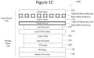
- FIG. 1Cillustrates a schematic side view diagram of a stack of components of a touch panel display in accordance with another aspect of the disclosure.
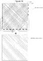
- FIG. 2Aillustrates a schematic plan view diagram of an X sensor layer of the touch panel displays of any of FIGS. 1A-1C .
- FIG. 2Billustrates a schematic plan view diagram of a Y sensor layer of the touch panel displays of any of FIGS. 1A-1C
- FIG. 2Cillustrates a schematic plan view diagram of a touch sensor and micro wire antenna of any of FIGS. 1A-1C .
- FIG. 3illustrates a schematic side view diagram of a stack of components of a touch panel display in accordance with another aspect of the disclosure.
- FIG. 4Aillustrates a schematic plan view diagram of a touch sensor and a micro wire antenna of FIG. 3 in accordance with an aspect of the disclosure.
- FIG. 4Billustrates a schematic plan view diagram of a touch sensor and a micro wire antenna of FIG. 3 in accordance with another aspect of the disclosure.
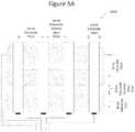
- FIGS. 5A-5Cillustrate schematic plan view diagrams of a portion of a touch panel display in accordance with another aspect of the disclosure.
- FIG. 6Aillustrates a schematic diagram of a wireless communication device in accordance with an aspect of the disclosure.
- FIG. 6Billustrates a schematic diagram of a wireless communication device in accordance with another aspect of the disclosure.
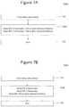
- FIG. 7Aillustrates a flowchart of a method of forming the touch sensor of FIGS. 1A-1C .
- FIG. 7Billustrates a flowchart of a method of forming the touch sensor of FIG. 3 .
- the present disclosureis directed to a touch panel for a display, the touch panel having a touch sensor configured to receive touch input, and an antenna located within or below the touch sensor.
- the antennais integrated in the touch panel without compromising the touch sensitivity or the optical quality of the display.
- FIG. 1Aillustrates a schematic side view diagram of a stack of components of a touch panel display 100 A in accordance with one aspect of the disclosure.
- the componentsin exaggerated dimension, comprise a stack of components of the touch panel display 100 A such as a panel display for a mobile phone or tablet.
- the touch panel display 100 Acomprises a touch panel 110 and a display panel 120 .
- the touch panel 110comprises a cover glass 112 , a two-layer touch sensor 114 ( 114 XA and 114 YA), a touch glass 116 , and a top polarizer 118 .
- the touch sensor 114has in layer 114 XA X electrodes, and in layer 114 YA Y electrodes. These components of the touch panel 110 are known, and thus for the sake of brevity their individual descriptions will not be provided here.
- the touch sensor 114is based on Projected Capacitive Touch (PCT).
- the touch sensor 114is made up of a matrix of sense electrode columns 114 X (X electrodes) and drive electrode rows 114 Y (Y electrodes) of conductive material, layered on sheets of glass.
- the drive electrode rows 114 Yare spaced apart from the sense electrode columns 114 X.
- the drive electrode rows 114 Ygenerate an electric field and the sense electrode rows 114 X receive the electric field. Overlapping portions of the drive electrode rows 114 Y and sense electrode columns 114 X form respective capacitors.
- the sense electrode columns 114 X (X electrodes) and drive electrode rows 114 Y (Y electrodes)can comprise indium tin oxide (ITO) transparent conductor, micro wire metal mesh, and/or one or more other materials as suitable for the intended purpose.
- ITOindium tin oxide
- the electrode columns and rowsmay be more generally known as electrode traces, and the terms columns and rows are not meant to be limiting. Further, the disclosure is not limited to PCT, but may be any touch panel technology as suitable for the intended purpose.
- the display panel 120which is located under the touch panel 110 , comprises a cover filter glass 121 , a color filter 122 , liquid crystal 123 , thin film transistor (TFT) layer 124 , TFT glass 125 , and bottom polarizer 126 . These components of the display panel 120 are known, and thus for the sake of brevity their individual descriptions will not be provided here.
- TFTthin film transistor
- the micro wire antennais located in the same layer as the touch sensor 114 , but at different locations in the layer than where the electrodes are located. In the case shown in FIG. 1A the micro wire antenna is located in the X sensor layer 114 XA of the touch sensor 114 , as opposed to the Y sensor layer 114 YA.
- the micro wire antennamay be a slot antenna, dipole antenna, or monopole antenna, or any other antenna that is one layer and is suitable for the intended purpose.
- a slot antennafor example, is generally a solid sheet of copper; a micro wire slot antenna has a same basic design but is comprised of micro wire mesh.
- the antennais connected by a feed. The feed is not transparent, so a transparent extension may be used. Options for connecting the feed include coplanar waveguide (CPW) and pogo pin.
- CPWcoplanar waveguide
- FIG. 1Billustrates a schematic side view diagram of a stack of components of a touch panel display 100 B in accordance with another aspect of the disclosure.
- the touch panel display 100 B of FIG. 1Bis similar to that of FIG. 1A , except that the micro wire antenna is located in layer 114 YA with the Y electrodes of the touch sensor 114 rather than the layer 114 XA with the X electrodes.
- FIG. 1Cillustrates a schematic side view diagram of a stack of components of a touch panel display 100 C in accordance with another aspect of the disclosure.
- the touch panel display 100 C of FIG. 1Cis similar to that of FIG. 1A , except that the micro wire antenna is located in both layer 114 XA with the X electrodes and layer 114 YA with the Y electrodes of the touch sensor.
- the micro wire antenna of this aspect of the disclosuremay be a patch antenna, or any other antenna that is comprised of two layers and suitable for the intended purpose.
- FIG. 2Aillustrates a schematic plan view diagram of an X sensor layer 114 AX of the touch sensor 114 of the touch panel display 100 of any of FIGS. 1A-1C .
- FIG. 2Billustrates a schematic plan view diagram of a Y sensor layer 114 AY of the touch panel display 100 of any of FIGS. 1A-1C .
- FIG. 2Cillustrates a schematic plan view diagram of a touch sensor 114 ( 114 AX and 114 AY) and micro wire antenna 210 of any of FIGS. 1A-1C .
- the micro wire antenna 210is shown as covering only a portion of the touch sensor 114 , though the disclosure is not limited in this respect.
- the micro wire antenna 210may cover any portion of the touch sensor 114 , including the entire surface area, based on transparency requirements. There is often a tradeoff between transparency and antenna performance.
- the micro wire antenna 210has a grid structure on a thin transparent film engineered to provide high conductivity integrated together with the touch sensor 114 in the touch panel display stack-up structure.
- the micro wire antenna 210has any of a number of antenna geometries to be optimized for antenna performance but without significant visual impact or display transparency degradation. This eliminates the need for antennas to be placed in the bezel area, thus enabling bezel-less, edge to edge display solutions.
- the micro wire antenna 210is a metal mesh with conductors that are, for example, approximately 4 um wide, about 2-5 ⁇ m or up to 7 um in thickness, with about 100 um pitch, and in such a case, may have a 92% transparency.
- a pitchis defined as the distance between two mesh. The specific dimensions depend on manufacturing capabilities and transparency requirements.
- the patterning of the antenna designcan be modified by trading between transparency and antenna performance.
- the micro wire antennamay be comprised of copper.
- a sheet resistance of these touch films with about 7 ⁇ m copper thicknessis as low as 0.003 ⁇ /square, which is smaller than that of ordinary Indium Tin Oxide (ITO) by four orders.
- the metal meshmay be any conductive material, such as silver.
- the metal meshmay alternatively be comprised of a hybrid material, for example, approximately 2 ⁇ m of silver, approximately 2 ⁇ m of copper, and approximately 3 ⁇ m of carbon nanotube for a thickness of approximately 7 ⁇ m.
- FIG. 3illustrates a schematic side view diagram of a stack of components of a touch panel display 300 in accordance with another aspect of the disclosure.
- the touch panel display 300 of FIG. 3is similar to that of FIG. 1A , except that the micro wire antenna 310 is located in a separate layer below the touch sensor 114 rather than in either or both of layer 114 XA with the X electrodes and layer 114 YA with the Y electrodes of the touch sensor 114 .
- the micro wire antennashould have a separation layer between it and Y-sensor layer 114 Y. This separation layer may be comprised of Polyethylene Terephthalate (PET).
- PETPolyethylene Terephthalate
- the micro wirehas been disclosed as being integrated in the touch sensor 114 in the X sensor layer 114 X and/or the Y sensor layer 114 Y. Alternatively, the micro wire has been disclosed as being located below the touch sensor 114 . The disclosure is not limited in these respects.
- the micro wire antennamay be located at any position within the touch panel display as suitable for the intended purpose.
- FIG. 4Aillustrates a schematic plan view diagram of a touch sensor 114 ( 114 X and 114 Y) and a micro wire antenna 410 A in accordance with an aspect of the disclosure.
- the micro wire antenna 410 Ais similar to the micro wire antenna 310 of FIG. 3 located below the touch sensor 114 .
- FIG. 4Billustrates a schematic plan view diagram of a touch sensor 114 ( 114 X and 114 Y) and a micro wire antenna 410 B in accordance with another aspect of the disclosure.
- the micro wire antenna 410 Bis similar to the micro wire antenna 310 of FIG. 3 , and is located below the touch sensor 114 .
- the mesh wirehas lines running all parallel to one another in one direction rather than perpendicular to one another in two directions.
- the mesh lines in any aspect of this disclosuremay run in one direction, two directions, or any number of directions as suitable for the intended purpose.
- FIGS. 5A-5Eillustrate a touch panel in accordance with another aspect of the disclosure.
- the aspect illustrated by these figuresdiffers from the previous aspects of the disclosure described above with respect to FIGS. 1-4 in that the antenna is located not within the touch sensor's active areas with the X and/or Y electrodes, but is instead located within dummy areas between electrodes.
- the antennais not necessarily comprised of micro wire, but may be comprised of an alternative material.
- FIG. 5Aillustrates a schematic plan view diagram of a portion of a touch panel 500 A.
- the touch panel 500 Acomprises sense electrode columns 514 X, sense electrode dummy areas 524 X, drive electrode rows 514 Y, and drive electrode dummy areas 524 Y.
- the sense electrode columns 514 X and drive electrode rows 514 Ycorrespond to the sense electrode columns 114 X and drive electrode rows 114 Y, respectively, as discussed above with respect to FIGS. 1-4 . Again, the electrode columns and rows may be more generally known as electrode traces.
- the sense electrode dummy areas 524 Xare located between the sense electrode columns 514 X.
- the drive electrode dummy areas 524 Yare located between the drive electrode rows 514 Y.
- the sense electrode dummy areas 524 X and the drive electrode dummy areas 524 Yare areas where there are no sense electrode columns 514 X or drive electrode rows 514 Y.
- the distance between respective drive electrode rows 114 Ycan be referred to as drive electrode row pitch and the distance between respective sense electrode columns 114 X can be referred to as sense electrode column pitch.
- the pitchcan be dependent on a target diameter of the touching object (e.g., a finger, stylus, etc.).
- the pitchcan be, for example, about 5 mm for finger touch.
- the areas between respective drive electrode rows 514 Y and also between the sense electrode columns 514 Xcan be referred to as “dummy areas.” For example, there are sense electrode dummy areas between adjacent sense electrode columns 514 X, and drive electrode dummy areas between adjacent drive electrode rows 514 Y.
- One or more antennascan be placed within the dummy areas (e.g., sense electrode dummy areas 524 X and/or the drive electrode dummy areas 524 Y).
- one or more conductive materials for antenna patterningcan be formed within one or more of the dummy areas.
- the materials for the antenna patterningcan include, for example, indium tin oxide (ITO) transparent conductor, micro wire metal mesh, and/or one or more other materials as would be understood by those skilled in the relevant arts.
- the materialscan be the same or different as those used for the touch sensor layers. Further, the materials can be transparent, semi-transparent, or opaque.
- the antennaby forming the antenna(s) in one or more dummy areas, the antenna can be placed directly on to the sensor layer patterns.
- FIG. 5Billustrates another schematic plan view diagram of a portion of the touch panel of FIG. 5A .
- the touch panel 500 Bcomprises sense/drive electrodes 514 and dummy areas 524 disposed between adjacent electrodes 514 (drive electrode 514 Y or sense electrodes 514 X).
- An antenna 540is located in the dummy areas 524 within section 550 .
- the antenna 540comprises an antenna driver 542 configured to drive a monopole antenna 544 .
- the disclosureis not limited to a single antenna, but may include any number of antennas as suitable. Also, the antenna need not be a monopole antenna, but may be any suitable antenna, similar to the antennas described above with respect to the aspects of FIGS. 1-4 .
- the dummy areas 524can include one or more materials, including, for example, indium tin oxide (ITO) transparent conductor, micro wire metal mesh, and/or one or more other materials as would be understood by those skilled in the relevant art.
- the materials within the dummy areas 524can be the same as those used for the one or more antennas 540 . By using the same materials, uniformity in the display can be achieved.
- the remaining portion of the dummy area 524 in which the antenna 540 is locatedcan also include the same or different materials as those dummy areas 524 not including an antenna 540 .
- FIG. 5Cillustrates another schematic plan view diagram of the touch panel of FIG. 5A .
- the touch panel 500 C shown in FIG. 5Cillustrates the other of the sense/drive electrodes 514 shown in FIG. 5B .
- the antenna 540 described with respect to FIG. 5Bis illustrated merely for the sake of perspective.
- the sense/drive electrode 514can include a toothed-structure having one or more teeth 514 - t located on one or more sides of the sense/drive electrode 514 .
- the toothed-structurecan create apertures 514 - a between adjacent teeth 514 - t to improve the antenna efficiency of one more antennas located within the dummy areas.
- the sense/drive electrode 514is not limited to the toothed-structure and can be another shape as would be understood by those skilled in the relevant art.
- the antenna 540may be located within the dummy areas 524 of the sense electrodes 514 X and/or drive electrodes 514 Y.
- FIG. 6Aillustrates a schematic diagram of a wireless communication device 600 A in accordance with an aspect of the disclosure.
- the wireless communication device 600 Acomprises a wireless communication device body 610 , a touch panel display 620 A, and an antenna 630 A.
- the touch panel display 620 Aextends across the entire surface area of the wireless communication device 600 A, as does the antenna 630 A.
- the wireless communication device 600 Amay be any wireless communication device, including but not limited to a mobile device—such as a laptop computer, a tablet computer, a mobile telephone or smartphone, a “phablet,” a personal digital assistant (PDA), and the like; and a wearable computing device—such as a computerized wrist watch or “smart” watch, computerized eyeglasses, and the like.
- the touch panel display 620 A and antenna 630 Amay alternatively be implemented in a stationary device, including but not limited to a personal computer (PC), a desktop computer, a computerized kiosk, an automotive/aeronautical/maritime in-dash computer terminal, and the like.
- FIG. 6Billustrates a schematic diagram of a wireless communication device 600 B in accordance with another aspect of the disclosure.
- the wireless communication device 600 Bis similar to the wireless communication device 600 A of FIG. 6A , except that rather than the antenna 630 B extending across the entire surface area of the wireless communication device 600 B, it extends across only a portion of the surface area.
- antenna 630 Bthere may be more than one antenna 630 B for different respective frequencies. Such multiple antennas should be placed in separate areas to avoid interference with one another.
- FIG. 7Aillustrates a flowchart of a method 700 A of forming the touch sensor 114 and antenna of FIGS. 1A-1C .
- Step 710a micro wire mesh is formed based on the touch sensor transparency and sensitivity requirements.
- a mask MXis formed with the micro wire antenna patterns and the X electrodes 114 X which coexist.
- a mask MYis formed with the micro wire antenna patterns and the Y electrodes 114 Y which coexist.
- the masks MX and MYare etched.
- FIG. 7Billustrates a flowchart of a method 700 B of forming the touch sensor 114 and micro wire antenna 310 of FIG. 3 .
- a micro wire meshis formed.
- a mask MXis formed with the X electrodes 114 X, and a mask MY is formed with the Y electrodes. Similarly, a mask MA is formed with the micro wire antenna patterns.
- the mask MX, mask MY, and mask MAare etched.
- the antennas as disclosed hereinachieve comparable performance to existing antennas without compromising the display optical properties.
- Example 1is a touch panel for a display, the touch panel comprising: a touch sensor configured to receive touch input; and a micro wire antenna located within or below the touch sensor.
- Example 2the subject matter of Example 1, wherein the micro wire antenna is located within the touch sensor.
- Example 3the subject matter of Example 2, wherein the touch sensor comprises a first portion located in a first layer, and a second portion located in a second layer.
- Example 4the subject matter of Example 3, wherein the micro wire antenna is located in the first layer.
- Example 5the subject matter of Example 4, wherein the micro wire antenna is a slot antenna.
- Example 6the subject matter of Example 3, wherein the micro wire antenna is located in the second layer.
- Example 7the subject matter of Example 6, wherein the micro wire antenna is a slot antenna.
- Example 8the subject matter of Example 3, wherein the micro wire antenna is located in both the first layer and the second layer.
- Example 9the subject matter of Example 8, wherein the micro wire antenna is a patch antenna.
- Example 10the subject matter of Example 2, wherein the micro wire antenna is located in a layer below the touch sensor.
- Example 11the subject matter of Example 1, wherein the micro wire antenna comprises a copper mesh.
- Example 12the subject matter of Example 1, further comprising a plurality of micro wire antennas.
- Example 13the subject matter of Example 1, wherein the micro wire antenna has a surface area that is substantially the same as the surface area of the touch panel display.
- Example 14the subject matter of Example 1, wherein the micro wire antenna has a surface area that is less than the surface area of the touch panel display.
- Example 15is a wireless communication device comprising the subject matter of Example 1.
- Example 16is a touch panel for a display, the touch panel comprising: a touch sensor comprising a plurality of electrode traces; at least one dummy area disposed between adjacent electrode traces of the plurality of electrode traces; and an antenna disposed in the at least one dummy area.
- Example 17the subject matter of Example 16, wherein the at least one dummy area comprises indium tin oxide (ITO) or a micro wire metal mesh.
- ITOindium tin oxide
- Example 18the subject matter of Example 16, wherein the antenna comprises indium tin oxide (ITO) or micro wire metal mesh.
- ITOindium tin oxide
- Example 19the subject matter of Example 16, wherein the at least one dummy area and the antenna comprise a same transparent conductive material.
- Example 20the subject matter of Example 16, wherein at least one of the plurality of electrode traces has a toothed-shaped structure.
- Example 21is a wireless communication device comprising the subject matter of Example 16.
- Example 22the subject matter of Example 21, further comprising a display panel located below the touch panel.
- Example 23is a method of forming a touch panel for a display, the method comprising: forming a micro wire mesh within or below a touch sensor of the touch panel; masking the micro wire mesh and touch sensor; and etching the micro wire mesh and touch sensor.
- Example 24the subject matter of Example 23, wherein the masking comprises masking with a first mask the touch sensor.
- Example 25the subject matter of Example 24, wherein the masking comprises masking with a second mask the micro wire mesh.
- Example 26the subject matter of any of Examples 1-4, wherein the micro wire antenna is a slot antenna.
- Example 27the subject matter of any of Examples 1-6, wherein the micro wire antenna is a slot antenna.
- Example 28the subject matter of any of Examples 1-8, wherein the micro wire antenna is a patch antenna.
- Example 29the subject matter of any of Examples 1-10, wherein the micro wire antenna comprises a copper mesh.
- Example 30the subject matter of any of Examples 1-11, further comprising a plurality of micro wire antennas.
- Example 31the subject matter of any of Examples 1-12, wherein the micro wire antenna has a surface area that is substantially the same as the surface area of the touch panel display.
- Example 32the subject matter of any of Examples 1-12, wherein the micro wire antenna has a surface area that is less than the surface area of the touch panel display.
- Example 33is a wireless communication device comprising the subject matter of any of Examples 1-16.
- Example 34the subject matter of any of Examples 16-17, wherein the antenna comprises indium tin oxide (ITO) or micro wire metal mesh.
- ITOindium tin oxide
- Example 35the subject matter of any of Examples 16-18, wherein the at least one dummy area and the antenna comprise a same transparent conductive material.
- Example 36the subject matter of any of Examples 16-19, wherein at least one of the plurality of electrode traces has a toothed-shaped structure.
- Example 37is a wireless communication device comprising the subject matter of any of Examples 16-20.
- Example 38is an apparatus substantially as shown and described.
- Example 39is a method substantially as shown and described.
Landscapes
- Engineering & Computer Science (AREA)
- General Engineering & Computer Science (AREA)
- Theoretical Computer Science (AREA)
- Human Computer Interaction (AREA)
- Physics & Mathematics (AREA)
- General Physics & Mathematics (AREA)
- Computer Networks & Wireless Communication (AREA)
- Position Input By Displaying (AREA)
- Support Of Aerials (AREA)
- Details Of Aerials (AREA)
Abstract
Description
Claims (19)
Priority Applications (3)
| Application Number | Priority Date | Filing Date | Title |
|---|---|---|---|
| US14/751,707US10551949B2 (en) | 2015-05-08 | 2015-06-26 | Display integrated antenna |
| CN201610203740.4ACN106125970A (en) | 2015-05-08 | 2016-04-01 | The antenna that display is integrated |
| EP16164128.7AEP3098699A1 (en) | 2015-05-08 | 2016-04-06 | Display integrated antenna |
Applications Claiming Priority (3)
| Application Number | Priority Date | Filing Date | Title |
|---|---|---|---|
| US201562158842P | 2015-05-08 | 2015-05-08 | |
| US201562158942P | 2015-05-08 | 2015-05-08 | |
| US14/751,707US10551949B2 (en) | 2015-05-08 | 2015-06-26 | Display integrated antenna |
Publications (2)
| Publication Number | Publication Date |
|---|---|
| US20160328057A1 US20160328057A1 (en) | 2016-11-10 |
| US10551949B2true US10551949B2 (en) | 2020-02-04 |
Family
ID=55699497
Family Applications (1)
| Application Number | Title | Priority Date | Filing Date |
|---|---|---|---|
| US14/751,707Active2035-10-11US10551949B2 (en) | 2015-05-08 | 2015-06-26 | Display integrated antenna |
Country Status (3)
| Country | Link |
|---|---|
| US (1) | US10551949B2 (en) |
| EP (1) | EP3098699A1 (en) |
| CN (1) | CN106125970A (en) |
Cited By (3)
| Publication number | Priority date | Publication date | Assignee | Title |
|---|---|---|---|---|
| US20190302962A1 (en)* | 2017-05-02 | 2019-10-03 | Samsung Display Co., Ltd. | Touch sensor and method of driving the same |
| US20240224767A1 (en)* | 2021-10-29 | 2024-07-04 | Beijing Boe Technology Development Co., Ltd. | Display assembly |
| US12176603B2 (en) | 2020-06-05 | 2024-12-24 | Samsung Electronics Co., Ltd. | Electronic device comprising antenna |
Families Citing this family (40)
| Publication number | Priority date | Publication date | Assignee | Title |
|---|---|---|---|---|
| US9917349B2 (en)* | 2015-01-30 | 2018-03-13 | Facebook, Inc. | Waveguides for digital communication devices |
| US10401548B2 (en)* | 2015-09-24 | 2019-09-03 | Intel Corporation | Integrated antenna with display uniformity |
| KR102469566B1 (en)* | 2016-03-31 | 2022-11-22 | 삼성전자주식회사 | An electronic device including an antenna apparatus |
| KR102666192B1 (en) | 2016-07-28 | 2024-05-14 | 삼성디스플레이 주식회사 | Display device |
| JP2019207446A (en)* | 2016-09-29 | 2019-12-05 | シャープ株式会社 | Touch panel display with antenna |
| CN106842665A (en)* | 2017-02-27 | 2017-06-13 | 联想(北京)有限公司 | Liquid crystal display module and electronic equipment |
| CN108539386B (en)* | 2017-03-01 | 2020-02-21 | 华为技术有限公司 | An antenna structure and wireless terminal |
| KR102009382B1 (en)* | 2017-03-03 | 2019-08-09 | 동우 화인켐 주식회사 | Touch sensor equipped with antenna |
| US10241631B2 (en) | 2017-03-21 | 2019-03-26 | Intel Corporation | Hybrid display integratable antennas using touch sensor trace and edge discontinuity structures |
| KR20180114771A (en)* | 2017-04-11 | 2018-10-19 | 주식회사 아모센스 | Touch screen sensor and touch screen panel having the same |
| CN110809807A (en)* | 2017-07-07 | 2020-02-18 | 东丽株式会社 | Manufacturing method of conductive film, manufacturing method of field effect transistor using the same, and manufacturing method of wireless communication device |
| US10249944B1 (en)* | 2017-09-25 | 2019-04-02 | Antwave Intellectual Property Limited | Systems, apparatus, and methods to improve antenna performance in electronic devices |
| CN107731855B (en)* | 2017-09-30 | 2020-07-17 | 京东方科技集团股份有限公司 | Array substrate, driving method and display device |
| WO2019103966A1 (en)* | 2017-11-27 | 2019-05-31 | Intel Corporation | Display integratable hybrid transparent antenna |
| KR102089458B1 (en)* | 2019-02-21 | 2020-03-16 | 동우 화인켐 주식회사 | Image display device including touch sensor and antenna |
| KR102099830B1 (en)* | 2019-06-17 | 2020-04-10 | 동우 화인켐 주식회사 | Antenna-combined module and display device including the same |
| CN112181189B (en)* | 2019-07-03 | 2024-05-14 | 夏普株式会社 | Position detection device with antenna function and display device |
| KR102633997B1 (en)* | 2019-07-12 | 2024-02-05 | 엘지디스플레이 주식회사 | Display Device Including Antenna And Method Of Fabricating The Same |
| WO2021014264A1 (en)* | 2019-07-19 | 2021-01-28 | 株式会社半導体エネルギー研究所 | Display device |
| KR102805061B1 (en)* | 2019-10-31 | 2025-05-12 | 삼성디스플레이 주식회사 | Display apparatus |
| KR102673524B1 (en)* | 2019-11-05 | 2024-06-11 | 삼성디스플레이 주식회사 | Electronic device |
| CN112928438B (en)* | 2019-11-20 | 2023-10-20 | 华为技术有限公司 | Cover plate and electronic equipment |
| WO2021102698A1 (en)* | 2019-11-26 | 2021-06-03 | 南昌欧菲光科技有限公司 | Touch-control screen, touch-control display and electronic device |
| WO2021112286A1 (en)* | 2019-12-05 | 2021-06-10 | 엘지전자 주식회사 | Electronic device having transparent antenna |
| CN210984952U (en)* | 2019-12-06 | 2020-07-10 | 昇印光电(昆山)股份有限公司 | Transparent antenna |
| CN115004137A (en)* | 2020-01-29 | 2022-09-02 | 华为技术有限公司 | Display stack with mmWave antenna capability |
| KR102796770B1 (en)* | 2020-02-14 | 2025-04-15 | 동우 화인켐 주식회사 | Antenna-inserted electrode structure and image display device including the same |
| KR102327554B1 (en)* | 2020-02-25 | 2021-11-16 | 동우 화인켐 주식회사 | Antenna-inserted electrode structure and image display device including the same |
| KR102684573B1 (en) | 2020-04-21 | 2024-07-16 | 삼성디스플레이 주식회사 | Electronic device |
| CN111610883B (en)* | 2020-05-20 | 2023-11-24 | 维沃移动通信有限公司 | Touch display screen and electronic equipment |
| CN111564692B (en)* | 2020-05-20 | 2021-09-07 | 维沃移动通信有限公司 | Electronic equipment |
| CN111562860B (en)* | 2020-05-20 | 2023-11-24 | 维沃移动通信有限公司 | Touch display screen and electronic equipment |
| JP2022029727A (en)* | 2020-08-05 | 2022-02-18 | 三菱電機株式会社 | Touch screen with built-in antenna and display device |
| KR102832198B1 (en) | 2020-09-24 | 2025-07-09 | 삼성전자주식회사 | Electronic device with a antenna moudulea |
| CN112286388B (en)* | 2020-10-29 | 2022-12-20 | 维沃移动通信有限公司 | Preparation method of electronic device and touch display screen |
| CN112486361B (en)* | 2020-12-20 | 2023-01-24 | 英特睿达(山东)电子科技有限公司 | Display touch screen member |
| KR20220148618A (en)* | 2021-04-29 | 2022-11-07 | 삼성전기주식회사 | Electronic device with display panel |
| CN113296635B (en)* | 2021-05-31 | 2022-07-12 | 武汉华星光电半导体显示技术有限公司 | Touch display panel and display device |
| CN115642387A (en)* | 2021-07-20 | 2023-01-24 | 北京京东方技术开发有限公司 | Antenna and antenna system |
| CN113612872A (en)* | 2021-07-27 | 2021-11-05 | 青岛海信移动通信技术股份有限公司 | Terminal equipment and millimeter wave radar module |
Citations (34)
| Publication number | Priority date | Publication date | Assignee | Title |
|---|---|---|---|---|
| US6362786B1 (en)* | 1999-02-18 | 2002-03-26 | International Business Machines Corporation | Patch antenna utilized in conjunction with an electronic apparatus |
| US6452549B1 (en)* | 2000-05-02 | 2002-09-17 | Bae Systems Information And Electronic Systems Integration Inc | Stacked, multi-band look-through antenna |
| US6480170B1 (en)* | 1998-04-15 | 2002-11-12 | Harada Industries (Europe) Limited | Patch antenna |
| US20040183788A1 (en) | 2003-01-30 | 2004-09-23 | Fujitsu Component Limited | Touch panel, and input device and electronic apparatus each equipped with the touch panel |
| US20070069971A1 (en)* | 2005-09-21 | 2007-03-29 | Hitachi Cable, Ltd. | Antenna and method of making the same |
| US20080028377A1 (en)* | 2006-07-26 | 2008-01-31 | Semiconductor Energy Laboratory Co., Ltd. | Semiconductor device, memory circuit, and machine language program generation device, and method for operating semiconductor device and memory circuit |
| US20080030424A1 (en)* | 2003-11-12 | 2008-02-07 | Kouji Muraoka | Antenna Pattern And Electromagnetic-Wave Energy Processing Device Having The Same |
| US20080266183A1 (en)* | 2007-04-27 | 2008-10-30 | Hitachi, Ltd | Skeleton equalizing antenna, RFID tag and RFID system using the same |
| US20090051620A1 (en)* | 2005-04-01 | 2009-02-26 | Tatsuo Ishibashi | Transparent Antenna for Display, Translucent Member for Display With an Antenna and Housing Component With an Antenna |
| US20090167699A1 (en)* | 2007-12-27 | 2009-07-02 | Apple Inc. | Touch screen rfid tag reader |
| US20100309162A1 (en)* | 2009-06-05 | 2010-12-09 | Sony Corporation | Touch panel, display panel, and display unit |
| US20100321325A1 (en)* | 2009-06-17 | 2010-12-23 | Springer Gregory A | Touch and display panel antennas |
| US20110005808A1 (en)* | 2009-07-10 | 2011-01-13 | Nanocomp Technologies, Inc. | Hybrid Conductors and Method of Making Same |
| US20110095990A1 (en)* | 2009-10-23 | 2011-04-28 | Harald Philipp | Interdigitated touchscreen electrodes |
| US20110096465A1 (en)* | 2009-10-23 | 2011-04-28 | Tsinghua University | Carbon nanotube composite, method for making the same, and electrochemical capacitor using the same |
| US20110267311A1 (en)* | 2010-04-30 | 2011-11-03 | Fu-Lin Yeh | Touch Panel Having Hidden Antenna |
| US20110298670A1 (en)* | 2010-06-04 | 2011-12-08 | Lg Electronics Inc. | Mobile terminal and method for fabricating antenna of mobile terminal |
| US20120086669A1 (en)* | 2010-10-08 | 2012-04-12 | Samsung Electronics Co. Ltd. | Slim type touch panel and mobile terminal including the same |
| US20120092284A1 (en) | 2010-09-30 | 2012-04-19 | Broadcom Corporation | Portable computing device including a three-dimensional touch screen |
| US20120094594A1 (en)* | 2010-09-30 | 2012-04-19 | Broadcom Corporation | Portable computing device with high-speed data communication |
| US20120162032A1 (en)* | 2010-12-22 | 2012-06-28 | Songnan Yang | Antenna integrated into a touch sensor of a touchscreen display |
| US20130162594A1 (en) | 2011-12-23 | 2013-06-27 | Cirque Corporation | Method for preventing interference of contactless card reader and touch functions when they are physically and logically bound together for improved authentication security |
| US20130181937A1 (en) | 2012-01-18 | 2013-07-18 | Chunghwa Picture Tubes, Ltd. | Dual-Mode Touch Sensing Apparatus |
| US20130196596A1 (en)* | 2012-01-27 | 2013-08-01 | Research In Motion Limited | Communications device and method for having integrated nfc antenna and touch screen display |
| CN103309513A (en) | 2013-06-24 | 2013-09-18 | 中国科学技术大学 | Handwriting input equipment comprising palm side surface information |
| US20130264390A1 (en)* | 2010-12-16 | 2013-10-10 | 3M Innovative Properties Company | Transparent Micropatterned RFID Antenna and Articles Incorporating Same |
| US20130341409A1 (en)* | 2012-06-21 | 2013-12-26 | Wistron Neweb Corporation | Multi-Function Radio-Frequency Device, Computer System and Method of Operating Multi-Function Radio-Frequency Device |
| US20140106684A1 (en)* | 2012-10-15 | 2014-04-17 | Qualcomm Mems Technologies, Inc. | Transparent antennas on a display device |
| US20140354906A1 (en)* | 2013-05-30 | 2014-12-04 | Wintek Corporation | Touch panel and method of adjusting the surface visual effect of touch panel |
| CN104485983A (en) | 2014-12-09 | 2015-04-01 | 深圳市汇顶科技股份有限公司 | Touch screen and terminal integrated with NFC (Near Filed Communication) antenna and near filed communication method thereof |
| US20150185928A1 (en)* | 2013-12-31 | 2015-07-02 | Lg Display Co., Ltd. | Touch panel |
| US9104263B2 (en)* | 2012-11-29 | 2015-08-11 | Wistron Neweb Corp. | Touch panel and a control method thereof |
| US9652073B2 (en)* | 2014-10-29 | 2017-05-16 | Samsung Electronics Co., Ltd. | Antenna device and electronic device having the same |
| US20170139520A1 (en)* | 2015-11-17 | 2017-05-18 | Jtouch Corporation | Metal mesh touch module with transparent antenna and touch display apparatus using same |
- 2015
- 2015-06-26USUS14/751,707patent/US10551949B2/enactiveActive
- 2016
- 2016-04-01CNCN201610203740.4Apatent/CN106125970A/enactivePending
- 2016-04-06EPEP16164128.7Apatent/EP3098699A1/ennot_activeCeased
Patent Citations (36)
| Publication number | Priority date | Publication date | Assignee | Title |
|---|---|---|---|---|
| US6480170B1 (en)* | 1998-04-15 | 2002-11-12 | Harada Industries (Europe) Limited | Patch antenna |
| US6362786B1 (en)* | 1999-02-18 | 2002-03-26 | International Business Machines Corporation | Patch antenna utilized in conjunction with an electronic apparatus |
| US6452549B1 (en)* | 2000-05-02 | 2002-09-17 | Bae Systems Information And Electronic Systems Integration Inc | Stacked, multi-band look-through antenna |
| US20040183788A1 (en) | 2003-01-30 | 2004-09-23 | Fujitsu Component Limited | Touch panel, and input device and electronic apparatus each equipped with the touch panel |
| US20080030424A1 (en)* | 2003-11-12 | 2008-02-07 | Kouji Muraoka | Antenna Pattern And Electromagnetic-Wave Energy Processing Device Having The Same |
| US20090051620A1 (en)* | 2005-04-01 | 2009-02-26 | Tatsuo Ishibashi | Transparent Antenna for Display, Translucent Member for Display With an Antenna and Housing Component With an Antenna |
| US20070069971A1 (en)* | 2005-09-21 | 2007-03-29 | Hitachi Cable, Ltd. | Antenna and method of making the same |
| US20080028377A1 (en)* | 2006-07-26 | 2008-01-31 | Semiconductor Energy Laboratory Co., Ltd. | Semiconductor device, memory circuit, and machine language program generation device, and method for operating semiconductor device and memory circuit |
| US20080266183A1 (en)* | 2007-04-27 | 2008-10-30 | Hitachi, Ltd | Skeleton equalizing antenna, RFID tag and RFID system using the same |
| US20090167699A1 (en)* | 2007-12-27 | 2009-07-02 | Apple Inc. | Touch screen rfid tag reader |
| US20100309162A1 (en)* | 2009-06-05 | 2010-12-09 | Sony Corporation | Touch panel, display panel, and display unit |
| US20100321325A1 (en)* | 2009-06-17 | 2010-12-23 | Springer Gregory A | Touch and display panel antennas |
| CN102804106A (en) | 2009-06-17 | 2012-11-28 | 苹果公司 | Touch and display panel antennas |
| US20110005808A1 (en)* | 2009-07-10 | 2011-01-13 | Nanocomp Technologies, Inc. | Hybrid Conductors and Method of Making Same |
| US20110095990A1 (en)* | 2009-10-23 | 2011-04-28 | Harald Philipp | Interdigitated touchscreen electrodes |
| US20110096465A1 (en)* | 2009-10-23 | 2011-04-28 | Tsinghua University | Carbon nanotube composite, method for making the same, and electrochemical capacitor using the same |
| US20110267311A1 (en)* | 2010-04-30 | 2011-11-03 | Fu-Lin Yeh | Touch Panel Having Hidden Antenna |
| US20110298670A1 (en)* | 2010-06-04 | 2011-12-08 | Lg Electronics Inc. | Mobile terminal and method for fabricating antenna of mobile terminal |
| EP2403064A1 (en) | 2010-06-04 | 2012-01-04 | LG Electronics Inc. | Mobile terminal and method for fabricating transparent antenna of mobile terminal |
| US20120092284A1 (en) | 2010-09-30 | 2012-04-19 | Broadcom Corporation | Portable computing device including a three-dimensional touch screen |
| US20120094594A1 (en)* | 2010-09-30 | 2012-04-19 | Broadcom Corporation | Portable computing device with high-speed data communication |
| US20120086669A1 (en)* | 2010-10-08 | 2012-04-12 | Samsung Electronics Co. Ltd. | Slim type touch panel and mobile terminal including the same |
| US20130264390A1 (en)* | 2010-12-16 | 2013-10-10 | 3M Innovative Properties Company | Transparent Micropatterned RFID Antenna and Articles Incorporating Same |
| US20120162032A1 (en)* | 2010-12-22 | 2012-06-28 | Songnan Yang | Antenna integrated into a touch sensor of a touchscreen display |
| US20130162594A1 (en) | 2011-12-23 | 2013-06-27 | Cirque Corporation | Method for preventing interference of contactless card reader and touch functions when they are physically and logically bound together for improved authentication security |
| US20130181937A1 (en) | 2012-01-18 | 2013-07-18 | Chunghwa Picture Tubes, Ltd. | Dual-Mode Touch Sensing Apparatus |
| US20130196596A1 (en)* | 2012-01-27 | 2013-08-01 | Research In Motion Limited | Communications device and method for having integrated nfc antenna and touch screen display |
| US20130341409A1 (en)* | 2012-06-21 | 2013-12-26 | Wistron Neweb Corporation | Multi-Function Radio-Frequency Device, Computer System and Method of Operating Multi-Function Radio-Frequency Device |
| US20140106684A1 (en)* | 2012-10-15 | 2014-04-17 | Qualcomm Mems Technologies, Inc. | Transparent antennas on a display device |
| US9104263B2 (en)* | 2012-11-29 | 2015-08-11 | Wistron Neweb Corp. | Touch panel and a control method thereof |
| US20140354906A1 (en)* | 2013-05-30 | 2014-12-04 | Wintek Corporation | Touch panel and method of adjusting the surface visual effect of touch panel |
| CN103309513A (en) | 2013-06-24 | 2013-09-18 | 中国科学技术大学 | Handwriting input equipment comprising palm side surface information |
| US20150185928A1 (en)* | 2013-12-31 | 2015-07-02 | Lg Display Co., Ltd. | Touch panel |
| US9652073B2 (en)* | 2014-10-29 | 2017-05-16 | Samsung Electronics Co., Ltd. | Antenna device and electronic device having the same |
| CN104485983A (en) | 2014-12-09 | 2015-04-01 | 深圳市汇顶科技股份有限公司 | Touch screen and terminal integrated with NFC (Near Filed Communication) antenna and near filed communication method thereof |
| US20170139520A1 (en)* | 2015-11-17 | 2017-05-18 | Jtouch Corporation | Metal mesh touch module with transparent antenna and touch display apparatus using same |
Non-Patent Citations (8)
| Title |
|---|
| Ahmed-Liyakath, Reconfigurable Antenna and RF Circuits Using Multi-Layer Stretchable Conductors, Graduate Theses and Dissertation, 2012, pp. 1-106, (Year: 2012).* |
| Extended European Search Report dated Nov. 2, 2016 for European Ptent Application No. 16164128.7. |
| Hecht et al, Emerging Transparent Electrodes based on Thin Films of Carbon Nanotubes, Graphene, and Metallic Nanostructures, Advanced Materials, 2011, pp. 1482-1513, (Year: 2011).* |
| Lee et al, Carbon-Nanotube Loaded Antenna-Based Ammonia Gas Sensor, IEEE, 2011 pp. 2065-2673, (Year: 2011).* |
| Office Action dated Jun. 6, 2018 for Chinese Application No. 201610203740.4. |
| Patel, Nanotube RFID Better Barcodes? Intelligent machines, 2010, pp. 1-5. (Year: 2010).* |
| Song et al, Stretchable and Reversibly Deformable Radio Frequency Antennas based on Silver Nanowires, ACS Publications, 2014, pp. 4248-4253, (Year: 2014).* |
| Stapelton et al, Highly conductive interwoven carbon nanotube and silver nanowire transparent electrodes, National Institute for Materials Science, 2013, pp. 1-8, (Year: 2013).* |
Cited By (5)
| Publication number | Priority date | Publication date | Assignee | Title |
|---|---|---|---|---|
| US20190302962A1 (en)* | 2017-05-02 | 2019-10-03 | Samsung Display Co., Ltd. | Touch sensor and method of driving the same |
| US10782826B2 (en)* | 2017-05-02 | 2020-09-22 | Samsung Display Co., Ltd. | Touch sensor and method of driving the same |
| US11061508B2 (en) | 2017-05-02 | 2021-07-13 | Samsung Display Co., Ltd. | Touch sensor and method of driving the same |
| US12176603B2 (en) | 2020-06-05 | 2024-12-24 | Samsung Electronics Co., Ltd. | Electronic device comprising antenna |
| US20240224767A1 (en)* | 2021-10-29 | 2024-07-04 | Beijing Boe Technology Development Co., Ltd. | Display assembly |
Also Published As
| Publication number | Publication date |
|---|---|
| CN106125970A (en) | 2016-11-16 |
| EP3098699A1 (en) | 2016-11-30 |
| US20160328057A1 (en) | 2016-11-10 |
Similar Documents
| Publication | Publication Date | Title |
|---|---|---|
| US10551949B2 (en) | Display integrated antenna | |
| US10073573B2 (en) | Conductive sheet, capacitive touch panel, display device | |
| US10013086B2 (en) | In cell touch panel and method for driving the same, and display device | |
| US10156923B2 (en) | In-cell touch display panel, driving method thereof and display device | |
| US10001889B2 (en) | Mesh electrode, sensing device, and electrode layer | |
| US9098134B2 (en) | Liquid crystal display device and method of manufacturing the same | |
| US9086766B2 (en) | Touch panel and touch display panel | |
| US20160274703A1 (en) | Conductive sheet, capacitive touch panel, and display device | |
| US11507235B2 (en) | Touch control device, touch control display substrate and display apparatus | |
| US20130063371A1 (en) | Touch panel | |
| US10496232B2 (en) | Capacitive touch panel | |
| CN106940605B (en) | Display panel | |
| US20160062518A1 (en) | Touch substrate and fabricating method thereof, and touch display apparatus | |
| US20130141369A1 (en) | Systems for displaying images | |
| US20150022738A1 (en) | Touch panel and method of fabricating a mesh of touch panel | |
| US20130155002A1 (en) | Mutual capacitance touch panel | |
| US9291847B2 (en) | Pixel unit and TFT-LCD with touch function | |
| US20190163306A1 (en) | Touch panel and touch display device and method for fabricating the same, touch display device (as amended) | |
| JP6084127B2 (en) | Transparent planar substrate with electrode and touch panel | |
| US20170024042A1 (en) | Touch panel for improving cross structure of sensing pattern | |
| US9563324B2 (en) | Touch panel substrate, electronic device, and production method for electronic device | |
| US20160239130A1 (en) | Touch panel and touch display device using the same | |
| US10042452B2 (en) | Touch sensor device and method for forming the same | |
| KR102047726B1 (en) | In-cell Touch Type Liquid Crystal Display and Method of fabricating the same | |
| US9652102B2 (en) | Touch panel |
Legal Events
| Date | Code | Title | Description |
|---|---|---|---|
| AS | Assignment | Owner name:INTEL CORPORATION, CALIFORNIA Free format text:ASSIGNMENT OF ASSIGNORS INTEREST;ASSIGNORS:CHAI, MEI;PARIKH, KUNJAL;HORINE, BRYCE D.;AND OTHERS;SIGNING DATES FROM 20150624 TO 20150629;REEL/FRAME:035988/0757 | |
| STPP | Information on status: patent application and granting procedure in general | Free format text:ADVISORY ACTION MAILED | |
| STPP | Information on status: patent application and granting procedure in general | Free format text:DOCKETED NEW CASE - READY FOR EXAMINATION | |
| STPP | Information on status: patent application and granting procedure in general | Free format text:NON FINAL ACTION MAILED | |
| STPP | Information on status: patent application and granting procedure in general | Free format text:RESPONSE TO NON-FINAL OFFICE ACTION ENTERED AND FORWARDED TO EXAMINER | |
| STPP | Information on status: patent application and granting procedure in general | Free format text:NOTICE OF ALLOWANCE MAILED -- APPLICATION RECEIVED IN OFFICE OF PUBLICATIONS | |
| STPP | Information on status: patent application and granting procedure in general | Free format text:PUBLICATIONS -- ISSUE FEE PAYMENT VERIFIED | |
| STCF | Information on status: patent grant | Free format text:PATENTED CASE | |
| AS | Assignment | Owner name:APPLE INC., CALIFORNIA Free format text:ASSIGNMENT OF ASSIGNORS INTEREST;ASSIGNOR:INTEL CORPORATION;REEL/FRAME:052414/0001 Effective date:20191130 | |
| MAFP | Maintenance fee payment | Free format text:PAYMENT OF MAINTENANCE FEE, 4TH YEAR, LARGE ENTITY (ORIGINAL EVENT CODE: M1551); ENTITY STATUS OF PATENT OWNER: LARGE ENTITY Year of fee payment:4 |