US10550964B2 - Methods and assemblies for pie cuts - Google Patents
Methods and assemblies for pie cutsDownload PDFInfo
- Publication number
- US10550964B2 US10550964B2US15/962,760US201815962760AUS10550964B2US 10550964 B2US10550964 B2US 10550964B2US 201815962760 AUS201815962760 AUS 201815962760AUS 10550964 B2US10550964 B2US 10550964B2
- Authority
- US
- United States
- Prior art keywords
- pie
- pieces
- cut
- section
- cutouts
- Prior art date
- Legal status (The legal status is an assumption and is not a legal conclusion. Google has not performed a legal analysis and makes no representation as to the accuracy of the status listed.)
- Active, expires
Links
Images


Classifications
- F—MECHANICAL ENGINEERING; LIGHTING; HEATING; WEAPONS; BLASTING
- F16—ENGINEERING ELEMENTS AND UNITS; GENERAL MEASURES FOR PRODUCING AND MAINTAINING EFFECTIVE FUNCTIONING OF MACHINES OR INSTALLATIONS; THERMAL INSULATION IN GENERAL
- F16L—PIPES; JOINTS OR FITTINGS FOR PIPES; SUPPORTS FOR PIPES, CABLES OR PROTECTIVE TUBING; MEANS FOR THERMAL INSULATION IN GENERAL
- F16L9/00—Rigid pipes
- F16L9/22—Pipes composed of a plurality of segments
- B—PERFORMING OPERATIONS; TRANSPORTING
- B21—MECHANICAL METAL-WORKING WITHOUT ESSENTIALLY REMOVING MATERIAL; PUNCHING METAL
- B21C—MANUFACTURE OF METAL SHEETS, WIRE, RODS, TUBES, PROFILES OR LIKE SEMI-MANUFACTURED PRODUCTS OTHERWISE THAN BY ROLLING; AUXILIARY OPERATIONS USED IN CONNECTION WITH METAL-WORKING WITHOUT ESSENTIALLY REMOVING MATERIAL
- B21C37/00—Manufacture of metal sheets, rods, wire, tubes, profiles or like semi-manufactured products, not otherwise provided for; Manufacture of tubes of special shape
- B21C37/06—Manufacture of metal sheets, rods, wire, tubes, profiles or like semi-manufactured products, not otherwise provided for; Manufacture of tubes of special shape of tubes or metal hoses; Combined procedures for making tubes, e.g. for making multi-wall tubes
- B21C37/08—Making tubes with welded or soldered seams
- F—MECHANICAL ENGINEERING; LIGHTING; HEATING; WEAPONS; BLASTING
- F01—MACHINES OR ENGINES IN GENERAL; ENGINE PLANTS IN GENERAL; STEAM ENGINES
- F01N—GAS-FLOW SILENCERS OR EXHAUST APPARATUS FOR MACHINES OR ENGINES IN GENERAL; GAS-FLOW SILENCERS OR EXHAUST APPARATUS FOR INTERNAL-COMBUSTION ENGINES
- F01N13/00—Exhaust or silencing apparatus characterised by constructional features
- F01N13/18—Construction facilitating manufacture, assembly, or disassembly
- F01N13/1805—Fixing exhaust manifolds, exhaust pipes or pipe sections to each other, to engine or to vehicle body
- F01N13/1811—Fixing exhaust manifolds, exhaust pipes or pipe sections to each other, to engine or to vehicle body with means permitting relative movement, e.g. compensation of thermal expansion or vibration
- F01N13/1816—Fixing exhaust manifolds, exhaust pipes or pipe sections to each other, to engine or to vehicle body with means permitting relative movement, e.g. compensation of thermal expansion or vibration the pipe sections being joined together by flexible tubular elements only, e.g. using bellows or strip-wound pipes
- F—MECHANICAL ENGINEERING; LIGHTING; HEATING; WEAPONS; BLASTING
- F16—ENGINEERING ELEMENTS AND UNITS; GENERAL MEASURES FOR PRODUCING AND MAINTAINING EFFECTIVE FUNCTIONING OF MACHINES OR INSTALLATIONS; THERMAL INSULATION IN GENERAL
- F16L—PIPES; JOINTS OR FITTINGS FOR PIPES; SUPPORTS FOR PIPES, CABLES OR PROTECTIVE TUBING; MEANS FOR THERMAL INSULATION IN GENERAL
- F16L43/00—Bends; Siphons
- F16L43/001—Bends; Siphons made of metal
- F—MECHANICAL ENGINEERING; LIGHTING; HEATING; WEAPONS; BLASTING
- F16—ENGINEERING ELEMENTS AND UNITS; GENERAL MEASURES FOR PRODUCING AND MAINTAINING EFFECTIVE FUNCTIONING OF MACHINES OR INSTALLATIONS; THERMAL INSULATION IN GENERAL
- F16L—PIPES; JOINTS OR FITTINGS FOR PIPES; SUPPORTS FOR PIPES, CABLES OR PROTECTIVE TUBING; MEANS FOR THERMAL INSULATION IN GENERAL
- F16L13/00—Non-disconnectable pipe joints, e.g. soldered, adhesive, or caulked joints
- F16L13/02—Welded joints
- F16L13/0209—Male-female welded joints
Definitions
- the present inventiondeals generally with pipe bending and metal working. More particularly, it deals with pre-manufactured pie cuts that assemble to create pipe bends.
- An exhaust pipetypically directs exhaust gasses collected from a manifold, for instance, away from the vehicle generating the gasses, typically, for example, to the rear or the direction opposite the direction of travel.
- the exhaust pipeis a straight pipe that leads directly from the engine to the rear of the vehicle.
- Makers of custom automobiles, motorcycles, and internal combustion enginessometimes orient the engine so that the exhaust pipe is connected at a location such that the pipe is not directed backward toward the rear. This may occur for aesthetic or performance reasons. In such cases, it is necessary to bend the exhaust pipe so that it directs the exhaust gasses in a safe direction.
- Bending pipeis a surprisingly tricky thing to do, requiring a fair amount of skill and special equipment such as a pipe bender.
- One alternative to bending pipeis to cut a section of pipe into series of pie cut pieces that can be assembled and welded together to form a curved section of piping.
- Making pie cutsis also tricky and requires a fairly high degree of skill and experience, as well as welding capability.
- pie cut pipe bendshave become fashionable because they look cool and make it relatively easy to bend the exhaust pipe into artistic shapes. Until now, pie cuts were custom-made for each specific job, even though exhaust pipe piping is commonly of standardize diameter and thickness.
- Pre-manufactured pie cut piecesprovide internal cutouts such that the cutouts from one piece are complementary to the cutouts of an adjacent piece so that the pieces connect by an interlocking friction fit.
- a series of pie cut piecescan be connected this way in concatenated fashion to produce a section of curved piping.
- the joints between the joined piecescan be sealed by welding or other suitable sealing means.
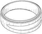
- FIG. 1is an isometric oblique view of a pie cut section of the present invention.
- FIG. 2is a side view of the pie cut section of FIG. 1 with bottom angle of 4.5 degrees and section line C-C.
- FIG. 3is a side view of the pie cut section of FIG. 1 with top angle of 4.5 degrees and section line A-A.
- FIG. 4is a sectional view along section line A-A of the pie cut section of FIG. 3 with radius horizontal tear drop detail cut.
- FIG. 5is an isometric oblique view of a stack of interlocked pie cut sections of the present invention.
- FIG. 6an isometric front view of the stack of FIG. 5 .
- FIG. 7is an isometric side view of the stack of FIG. 5 with section line B-B.
- FIG. 8is a sectional view along section line B-B of the stack of FIG. 5 .
- inventionis not intended to refer to any particular embodiment or otherwise limit the scope of the disclosure. Although one or more of these embodiments may be preferred, the embodiments disclosed should not be interpreted, or otherwise used, as limiting the scope of the disclosure, including the claims.
- discussionhas broad application, and the discussion of any embodiment is meant only to be exemplary of that embodiment, and not intended to intimate that the scope of the disclosure, including the claims, is limited to that embodiment.
- connectionor “connected” or equivalent term where used if at all is intended to mean either an indirect or direct connection.
- first componentconnects to a second component, that connection may be through a direct connection or through an indirect connection via other components and connections.
- FIG. 1is an isometric oblique view of a pie cut section of the present invention.
- FIG. 2is a side view of the pie cut section of FIG. 1 with bottom angle ( 1 ) and top angle ( 2 ), both of 4.5 degrees, and section line C-C.
- FIG. 3is a side view of the pie cut section of FIG. 1 with top angle of 4.5 degrees and section line A-A.
- Horizontal tear drop shape detail ( 3 )is cut out of the exterior surface, also referred to herein sometimes as the outside wall, of the section material.
- FIG. 4is a sectional view along section line A-A of the pie cut section of FIG. 3 with radius horizontal tear drop detail cut.
- the angled cut of the piecedefines a narrow end and a wide end.
- the outside wall ( 4 ) and the inside wall ( 5 )are called out on the wide side of the piece to help orient the reader.
- the narrow side of the sectionprovides interlocking step ( 6 ) on the outside wall ( 4 ) and the wide interlocking step ( 7 ) on inside wall ( 5 ).
- FIG. 5is an isometric oblique view of a stack of interlocked pie cut sections of the present invention.
- FIG. 6an isometric front view of the stack of FIG. 5 .
- FIG. 7is an isometric side view of the stack ( 8 ) of FIG. 5 with section line B-B. An exterior view of weld chamfer ( 9 ) on outside wall ( 4 ) is illustrated.
- FIG. 8is a sectional view along section line B-B of the stack of FIG. 5 .
- Inside wall interlocking step ( 10 )interlocks with outside wall interlocking step ( 11 ).
- a consequence of the 4.5 degree angle cutsis that when the sections, also called pieces, are stacked as in FIG. 5 , a curved portion of piping is produced.
- the tightness of the curved portioncan be varied by changing the degree angle of the pie cuts such that a smaller angle pie cut produces greater diameter curved portion and a larger degree angle cut produces a smaller diameter curved portion.
- Circumferential cut out steps ( 6 ) and ( 7 )result in the pieces interlocking when they are stacked, as seen in cross-section view of FIG. 8 as indicated by interlocked steps ( 10 ) and ( 11 ).
- the seams between the sectionscan be sealed by welding or other suitable sealing means, depending on the material the pieces are fabricated from and the use to which the piping will be put.
- the present inventionstandardizes pie cut pipe bends. Additionally, shops that do not have the equipment or skill set to make pie cuts themselves have access to pie cut pieces so that they can be competitive with trends in the industry.
Landscapes
- Engineering & Computer Science (AREA)
- General Engineering & Computer Science (AREA)
- Mechanical Engineering (AREA)
- Chemical & Material Sciences (AREA)
- Combustion & Propulsion (AREA)
- Exhaust Silencers (AREA)
- Butt Welding And Welding Of Specific Article (AREA)
Abstract
Description
Claims (1)
Priority Applications (1)
| Application Number | Priority Date | Filing Date | Title |
|---|---|---|---|
| US15/962,760US10550964B2 (en) | 2017-04-27 | 2018-04-25 | Methods and assemblies for pie cuts |
Applications Claiming Priority (2)
| Application Number | Priority Date | Filing Date | Title |
|---|---|---|---|
| US201762490719P | 2017-04-27 | 2017-04-27 | |
| US15/962,760US10550964B2 (en) | 2017-04-27 | 2018-04-25 | Methods and assemblies for pie cuts |
Publications (2)
| Publication Number | Publication Date |
|---|---|
| US20180313472A1 US20180313472A1 (en) | 2018-11-01 |
| US10550964B2true US10550964B2 (en) | 2020-02-04 |
Family
ID=63916542
Family Applications (1)
| Application Number | Title | Priority Date | Filing Date |
|---|---|---|---|
| US15/962,760Active2038-05-31US10550964B2 (en) | 2017-04-27 | 2018-04-25 | Methods and assemblies for pie cuts |
Country Status (1)
| Country | Link |
|---|---|
| US (1) | US10550964B2 (en) |
Families Citing this family (1)
| Publication number | Priority date | Publication date | Assignee | Title |
|---|---|---|---|---|
| DE202022105138U1 (en) | 2022-09-12 | 2022-10-05 | German Welding Tools Gmbh | Motor vehicle pipe assembly with at least two sections - pie cut |
Citations (13)
| Publication number | Priority date | Publication date | Assignee | Title |
|---|---|---|---|---|
| US2823703A (en)* | 1955-07-26 | 1958-02-18 | Jr Otto Nusser | Flexible pipe |
| US4594734A (en)* | 1984-12-20 | 1986-06-17 | The United States Of America As Represented By The Administrator Of The National Aeronautics And Space Administration | Shoulder and hip joint for hard space suits |
| US4800985A (en)* | 1985-02-18 | 1989-01-31 | Honda Giken Kogyo Kabushiki Kaisha | Silencer with a side branch |
| US4807370A (en)* | 1987-07-06 | 1989-02-28 | Anterior, Inc. | Adjustable tube bending pattern device |
| US5473815A (en)* | 1993-03-01 | 1995-12-12 | Lindab Ab | Method for producing a connector for fluid pipe elements |
| US20050056333A1 (en)* | 2003-09-11 | 2005-03-17 | Tsubakimoto Chain Co. | Cable or the like protection and guide device |
| US7097804B2 (en)* | 2002-08-09 | 2006-08-29 | The Boeing Company | Thermoplastic laminate duct |
| US7360799B1 (en)* | 2004-08-17 | 2008-04-22 | Price Todd C | Insulation cladding for bends |
| US20090293979A1 (en)* | 2006-10-24 | 2009-12-03 | Kenneth Latimer Scott | Method of lining pre-existing pipes or passages and apparatus therefor |
| US8047236B2 (en)* | 2008-09-12 | 2011-11-01 | Boston Scientific Scimed, Inc. | Flexible conduit with locking element |
| US20140345739A1 (en)* | 2011-12-29 | 2014-11-27 | Geoffrey Stephen Graham | Flexible pipe body and method of manufacture |
| US9476538B2 (en)* | 2013-11-11 | 2016-10-25 | Dong In Engineering Co., Ltd. | Pipe insulation apparatus having finishing cover of compression-bonded structure |
| US10323711B2 (en)* | 2017-05-23 | 2019-06-18 | Ford Global Technologies, Llc | Breakable duct for use with a motor vehicle air induction system |
- 2018
- 2018-04-25USUS15/962,760patent/US10550964B2/enactiveActive
Patent Citations (13)
| Publication number | Priority date | Publication date | Assignee | Title |
|---|---|---|---|---|
| US2823703A (en)* | 1955-07-26 | 1958-02-18 | Jr Otto Nusser | Flexible pipe |
| US4594734A (en)* | 1984-12-20 | 1986-06-17 | The United States Of America As Represented By The Administrator Of The National Aeronautics And Space Administration | Shoulder and hip joint for hard space suits |
| US4800985A (en)* | 1985-02-18 | 1989-01-31 | Honda Giken Kogyo Kabushiki Kaisha | Silencer with a side branch |
| US4807370A (en)* | 1987-07-06 | 1989-02-28 | Anterior, Inc. | Adjustable tube bending pattern device |
| US5473815A (en)* | 1993-03-01 | 1995-12-12 | Lindab Ab | Method for producing a connector for fluid pipe elements |
| US7097804B2 (en)* | 2002-08-09 | 2006-08-29 | The Boeing Company | Thermoplastic laminate duct |
| US20050056333A1 (en)* | 2003-09-11 | 2005-03-17 | Tsubakimoto Chain Co. | Cable or the like protection and guide device |
| US7360799B1 (en)* | 2004-08-17 | 2008-04-22 | Price Todd C | Insulation cladding for bends |
| US20090293979A1 (en)* | 2006-10-24 | 2009-12-03 | Kenneth Latimer Scott | Method of lining pre-existing pipes or passages and apparatus therefor |
| US8047236B2 (en)* | 2008-09-12 | 2011-11-01 | Boston Scientific Scimed, Inc. | Flexible conduit with locking element |
| US20140345739A1 (en)* | 2011-12-29 | 2014-11-27 | Geoffrey Stephen Graham | Flexible pipe body and method of manufacture |
| US9476538B2 (en)* | 2013-11-11 | 2016-10-25 | Dong In Engineering Co., Ltd. | Pipe insulation apparatus having finishing cover of compression-bonded structure |
| US10323711B2 (en)* | 2017-05-23 | 2019-06-18 | Ford Global Technologies, Llc | Breakable duct for use with a motor vehicle air induction system |
Also Published As
| Publication number | Publication date |
|---|---|
| US20180313472A1 (en) | 2018-11-01 |
Similar Documents
| Publication | Publication Date | Title |
|---|---|---|
| US7658419B2 (en) | Fitting and method for manufacturing a fitting | |
| US8240678B2 (en) | Connecting structure of metal plates | |
| CN110249168A (en) | Mechanical links for mechanically and structurally pipe fitting | |
| KR101788519B1 (en) | Metal joined body and method for manufacturing metal joined body | |
| KR20080052677A (en) | How to Form Bent Sheet Material and Bonding Part | |
| US3979809A (en) | Pipe elbow and method of making same | |
| US10550964B2 (en) | Methods and assemblies for pie cuts | |
| US20120223519A1 (en) | Pipe joining structure | |
| US10563570B2 (en) | High temperature capable joint assembly for use in air-to-air aftercoolers (ATAAC) | |
| US5979035A (en) | Method of producing metal gasket | |
| CN102947020B (en) | Structural member | |
| JP2012501408A (en) | Piston for internal combustion engine | |
| JPH09125948A (en) | Method for assembling exhaust-system piping of engine and its assembled structure | |
| US5901988A (en) | Structure for coupling pipe with breeches pipe | |
| MY130349A (en) | Joint construction of column member steel pipes | |
| US9371851B2 (en) | Method of forming joint for interconnecting adjacent elements and joint formed thereby | |
| EP2975354A1 (en) | Connector for a heat exchanger | |
| JP2017186795A (en) | Joint structure of steel pipe pile and connection steel pipe pile | |
| JP2000356294A (en) | Bend tube manufacturing method | |
| US7523838B2 (en) | Housing | |
| JP6975002B2 (en) | gasket | |
| JP2006150397A (en) | Ring projection welding method and ring projection welding member | |
| JP5607560B2 (en) | Manufacturing method of metal parts | |
| WO2011085929A1 (en) | Manifold assembly | |
| JP2007262927A (en) | Damping cover device |
Legal Events
| Date | Code | Title | Description |
|---|---|---|---|
| FEPP | Fee payment procedure | Free format text:ENTITY STATUS SET TO UNDISCOUNTED (ORIGINAL EVENT CODE: BIG.); ENTITY STATUS OF PATENT OWNER: SMALL ENTITY | |
| FEPP | Fee payment procedure | Free format text:ENTITY STATUS SET TO SMALL (ORIGINAL EVENT CODE: SMAL); ENTITY STATUS OF PATENT OWNER: SMALL ENTITY | |
| STPP | Information on status: patent application and granting procedure in general | Free format text:DOCKETED NEW CASE - READY FOR EXAMINATION | |
| STPP | Information on status: patent application and granting procedure in general | Free format text:NON FINAL ACTION MAILED | |
| STPP | Information on status: patent application and granting procedure in general | Free format text:RESPONSE TO NON-FINAL OFFICE ACTION ENTERED AND FORWARDED TO EXAMINER | |
| STPP | Information on status: patent application and granting procedure in general | Free format text:PUBLICATIONS -- ISSUE FEE PAYMENT RECEIVED | |
| STPP | Information on status: patent application and granting procedure in general | Free format text:PUBLICATIONS -- ISSUE FEE PAYMENT VERIFIED | |
| STCF | Information on status: patent grant | Free format text:PATENTED CASE | |
| FEPP | Fee payment procedure | Free format text:MAINTENANCE FEE REMINDER MAILED (ORIGINAL EVENT CODE: REM.); ENTITY STATUS OF PATENT OWNER: SMALL ENTITY | |
| FEPP | Fee payment procedure | Free format text:SURCHARGE FOR LATE PAYMENT, SMALL ENTITY (ORIGINAL EVENT CODE: M2554); ENTITY STATUS OF PATENT OWNER: SMALL ENTITY | |
| MAFP | Maintenance fee payment | Free format text:PAYMENT OF MAINTENANCE FEE, 4TH YR, SMALL ENTITY (ORIGINAL EVENT CODE: M2551); ENTITY STATUS OF PATENT OWNER: SMALL ENTITY Year of fee payment:4 |