US10549154B2 - Workout sensing system - Google Patents
Workout sensing systemDownload PDFInfo
- Publication number
- US10549154B2 US10549154B2US15/690,459US201715690459AUS10549154B2US 10549154 B2US10549154 B2US 10549154B2US 201715690459 AUS201715690459 AUS 201715690459AUS 10549154 B2US10549154 B2US 10549154B2
- Authority
- US
- United States
- Prior art keywords
- workout
- sensing system
- connected components
- strength training
- bar
- Prior art date
- Legal status (The legal status is an assumption and is not a legal conclusion. Google has not performed a legal analysis and makes no representation as to the accuracy of the status listed.)
- Expired - Fee Related, expires
Links
Images


Classifications
- A—HUMAN NECESSITIES
- A63—SPORTS; GAMES; AMUSEMENTS
- A63B—APPARATUS FOR PHYSICAL TRAINING, GYMNASTICS, SWIMMING, CLIMBING, OR FENCING; BALL GAMES; TRAINING EQUIPMENT
- A63B24/00—Electric or electronic controls for exercising apparatus of preceding groups; Controlling or monitoring of exercises, sportive games, training or athletic performances
- A63B24/0062—Monitoring athletic performances, e.g. for determining the work of a user on an exercise apparatus, the completed jogging or cycling distance
- A—HUMAN NECESSITIES
- A63—SPORTS; GAMES; AMUSEMENTS
- A63B—APPARATUS FOR PHYSICAL TRAINING, GYMNASTICS, SWIMMING, CLIMBING, OR FENCING; BALL GAMES; TRAINING EQUIPMENT
- A63B21/00—Exercising apparatus for developing or strengthening the muscles or joints of the body by working against a counterforce, with or without measuring devices
- A63B21/06—User-manipulated weights
- A63B21/062—User-manipulated weights including guide for vertical or non-vertical weights or array of weights to move against gravity forces
- A63B21/0626—User-manipulated weights including guide for vertical or non-vertical weights or array of weights to move against gravity forces with substantially vertical guiding means
- A63B21/0628—User-manipulated weights including guide for vertical or non-vertical weights or array of weights to move against gravity forces with substantially vertical guiding means for vertical array of weights
- A63B21/063—Weight selecting means
- A—HUMAN NECESSITIES
- A63—SPORTS; GAMES; AMUSEMENTS
- A63B—APPARATUS FOR PHYSICAL TRAINING, GYMNASTICS, SWIMMING, CLIMBING, OR FENCING; BALL GAMES; TRAINING EQUIPMENT
- A63B21/00—Exercising apparatus for developing or strengthening the muscles or joints of the body by working against a counterforce, with or without measuring devices
- A63B21/06—User-manipulated weights
- A63B21/072—Dumb-bells, bar-bells or the like, e.g. weight discs having an integral peripheral handle
- A63B21/0724—Bar-bells; Hand bars
- A—HUMAN NECESSITIES
- A63—SPORTS; GAMES; AMUSEMENTS
- A63B—APPARATUS FOR PHYSICAL TRAINING, GYMNASTICS, SWIMMING, CLIMBING, OR FENCING; BALL GAMES; TRAINING EQUIPMENT
- A63B21/00—Exercising apparatus for developing or strengthening the muscles or joints of the body by working against a counterforce, with or without measuring devices
- A63B21/06—User-manipulated weights
- A63B21/072—Dumb-bells, bar-bells or the like, e.g. weight discs having an integral peripheral handle
- A63B21/075—Dumb-bells, bar-bells or the like, e.g. weight discs having an integral peripheral handle with variable weights, e.g. weight systems with weight selecting means for bar-bells or dumb-bells
- A—HUMAN NECESSITIES
- A63—SPORTS; GAMES; AMUSEMENTS
- A63B—APPARATUS FOR PHYSICAL TRAINING, GYMNASTICS, SWIMMING, CLIMBING, OR FENCING; BALL GAMES; TRAINING EQUIPMENT
- A63B21/00—Exercising apparatus for developing or strengthening the muscles or joints of the body by working against a counterforce, with or without measuring devices
- A63B21/15—Arrangements for force transmissions
- A63B21/151—Using flexible elements for reciprocating movements, e.g. ropes or chains
- A—HUMAN NECESSITIES
- A63—SPORTS; GAMES; AMUSEMENTS
- A63B—APPARATUS FOR PHYSICAL TRAINING, GYMNASTICS, SWIMMING, CLIMBING, OR FENCING; BALL GAMES; TRAINING EQUIPMENT
- A63B21/00—Exercising apparatus for developing or strengthening the muscles or joints of the body by working against a counterforce, with or without measuring devices
- A63B21/40—Interfaces with the user related to strength training; Details thereof
- A63B21/4027—Specific exercise interfaces
- A63B21/4033—Handles, pedals, bars or platforms
- A63B21/4035—Handles, pedals, bars or platforms for operation by hand
- A—HUMAN NECESSITIES
- A63—SPORTS; GAMES; AMUSEMENTS
- A63B—APPARATUS FOR PHYSICAL TRAINING, GYMNASTICS, SWIMMING, CLIMBING, OR FENCING; BALL GAMES; TRAINING EQUIPMENT
- A63B24/00—Electric or electronic controls for exercising apparatus of preceding groups; Controlling or monitoring of exercises, sportive games, training or athletic performances
- A63B24/0003—Analysing the course of a movement or motion sequences during an exercise or trainings sequence, e.g. swing for golf or tennis
- A—HUMAN NECESSITIES
- A63—SPORTS; GAMES; AMUSEMENTS
- A63B—APPARATUS FOR PHYSICAL TRAINING, GYMNASTICS, SWIMMING, CLIMBING, OR FENCING; BALL GAMES; TRAINING EQUIPMENT
- A63B24/00—Electric or electronic controls for exercising apparatus of preceding groups; Controlling or monitoring of exercises, sportive games, training or athletic performances
- A63B24/0075—Means for generating exercise programs or schemes, e.g. computerized virtual trainer, e.g. using expert databases
- A—HUMAN NECESSITIES
- A63—SPORTS; GAMES; AMUSEMENTS
- A63B—APPARATUS FOR PHYSICAL TRAINING, GYMNASTICS, SWIMMING, CLIMBING, OR FENCING; BALL GAMES; TRAINING EQUIPMENT
- A63B71/00—Games or sports accessories not covered in groups A63B1/00 - A63B69/00
- A63B71/06—Indicating or scoring devices for games or players, or for other sports activities
- A63B71/0619—Displays, user interfaces and indicating devices, specially adapted for sport equipment, e.g. display mounted on treadmills
- A63B71/0622—Visual, audio or audio-visual systems for entertaining, instructing or motivating the user
- H—ELECTRICITY
- H04—ELECTRIC COMMUNICATION TECHNIQUE
- H04W—WIRELESS COMMUNICATION NETWORKS
- H04W4/00—Services specially adapted for wireless communication networks; Facilities therefor
- H04W4/30—Services specially adapted for particular environments, situations or purposes
- H04W4/38—Services specially adapted for particular environments, situations or purposes for collecting sensor information
- A—HUMAN NECESSITIES
- A63—SPORTS; GAMES; AMUSEMENTS
- A63B—APPARATUS FOR PHYSICAL TRAINING, GYMNASTICS, SWIMMING, CLIMBING, OR FENCING; BALL GAMES; TRAINING EQUIPMENT
- A63B2220/00—Measuring of physical parameters relating to sporting activity
- A63B2220/17—Counting, e.g. counting periodical movements, revolutions or cycles, or including further data processing to determine distances or speed
- A—HUMAN NECESSITIES
- A63—SPORTS; GAMES; AMUSEMENTS
- A63B—APPARATUS FOR PHYSICAL TRAINING, GYMNASTICS, SWIMMING, CLIMBING, OR FENCING; BALL GAMES; TRAINING EQUIPMENT
- A63B2220/00—Measuring of physical parameters relating to sporting activity
- A63B2220/20—Distances or displacements
- A—HUMAN NECESSITIES
- A63—SPORTS; GAMES; AMUSEMENTS
- A63B—APPARATUS FOR PHYSICAL TRAINING, GYMNASTICS, SWIMMING, CLIMBING, OR FENCING; BALL GAMES; TRAINING EQUIPMENT
- A63B2220/00—Measuring of physical parameters relating to sporting activity
- A63B2220/40—Acceleration
- A—HUMAN NECESSITIES
- A63—SPORTS; GAMES; AMUSEMENTS
- A63B—APPARATUS FOR PHYSICAL TRAINING, GYMNASTICS, SWIMMING, CLIMBING, OR FENCING; BALL GAMES; TRAINING EQUIPMENT
- A63B2220/00—Measuring of physical parameters relating to sporting activity
- A63B2220/50—Force related parameters
- A—HUMAN NECESSITIES
- A63—SPORTS; GAMES; AMUSEMENTS
- A63B—APPARATUS FOR PHYSICAL TRAINING, GYMNASTICS, SWIMMING, CLIMBING, OR FENCING; BALL GAMES; TRAINING EQUIPMENT
- A63B2220/00—Measuring of physical parameters relating to sporting activity
- A63B2220/50—Force related parameters
- A63B2220/56—Pressure
- A—HUMAN NECESSITIES
- A63—SPORTS; GAMES; AMUSEMENTS
- A63B—APPARATUS FOR PHYSICAL TRAINING, GYMNASTICS, SWIMMING, CLIMBING, OR FENCING; BALL GAMES; TRAINING EQUIPMENT
- A63B2220/00—Measuring of physical parameters relating to sporting activity
- A63B2220/62—Time or time measurement used for time reference, time stamp, master time or clock signal
- A—HUMAN NECESSITIES
- A63—SPORTS; GAMES; AMUSEMENTS
- A63B—APPARATUS FOR PHYSICAL TRAINING, GYMNASTICS, SWIMMING, CLIMBING, OR FENCING; BALL GAMES; TRAINING EQUIPMENT
- A63B2220/00—Measuring of physical parameters relating to sporting activity
- A63B2220/80—Special sensors, transducers or devices therefor
- A63B2220/83—Special sensors, transducers or devices therefor characterised by the position of the sensor
- A63B2220/833—Sensors arranged on the exercise apparatus or sports implement
- A—HUMAN NECESSITIES
- A63—SPORTS; GAMES; AMUSEMENTS
- A63B—APPARATUS FOR PHYSICAL TRAINING, GYMNASTICS, SWIMMING, CLIMBING, OR FENCING; BALL GAMES; TRAINING EQUIPMENT
- A63B2225/00—Miscellaneous features of sport apparatus, devices or equipment
- A63B2225/15—Miscellaneous features of sport apparatus, devices or equipment with identification means that can be read by electronic means
- A—HUMAN NECESSITIES
- A63—SPORTS; GAMES; AMUSEMENTS
- A63B—APPARATUS FOR PHYSICAL TRAINING, GYMNASTICS, SWIMMING, CLIMBING, OR FENCING; BALL GAMES; TRAINING EQUIPMENT
- A63B2225/00—Miscellaneous features of sport apparatus, devices or equipment
- A63B2225/20—Miscellaneous features of sport apparatus, devices or equipment with means for remote communication, e.g. internet or the like
- A—HUMAN NECESSITIES
- A63—SPORTS; GAMES; AMUSEMENTS
- A63B—APPARATUS FOR PHYSICAL TRAINING, GYMNASTICS, SWIMMING, CLIMBING, OR FENCING; BALL GAMES; TRAINING EQUIPMENT
- A63B2225/00—Miscellaneous features of sport apparatus, devices or equipment
- A63B2225/50—Wireless data transmission, e.g. by radio transmitters or telemetry
- H—ELECTRICITY
- H04—ELECTRIC COMMUNICATION TECHNIQUE
- H04W—WIRELESS COMMUNICATION NETWORKS
- H04W4/00—Services specially adapted for wireless communication networks; Facilities therefor
- H04W4/80—Services using short range communication, e.g. near-field communication [NFC], radio-frequency identification [RFID] or low energy communication
- H—ELECTRICITY
- H04—ELECTRIC COMMUNICATION TECHNIQUE
- H04W—WIRELESS COMMUNICATION NETWORKS
- H04W84/00—Network topologies
- H04W84/02—Hierarchically pre-organised networks, e.g. paging networks, cellular networks, WLAN [Wireless Local Area Network] or WLL [Wireless Local Loop]
- H04W84/10—Small scale networks; Flat hierarchical networks
- H04W84/12—WLAN [Wireless Local Area Networks]
Definitions
- This applicationrelates generally to the field of physical fitness. More specifically, this application relates to fitness equipment.
- Athletesutilize workout equipment off the field to supplement their athletic performance on the field in sports such as football, cycling, basketball, water polo, and running.
- Bodybuildersuse workout equipment to improve their physique and win competitions.
- Members of the militaryuse workout equipment to maintain rigorous physical performance standards for the purpose of staying physically fit for duty.
- Some gym goersuse workout equipment with a focus on burning calories and losing weight.
- Othersuse workout equipment to strengthen their bodies and consequently improve physical and mental health.
- Athletes, bodybuilders, and anyone following a serious training programwill track their progress so as to make adjustments and improvements that lead to accomplishing their fitness objectives. Tracking progress helps maintain consistency even when the bodily improvements are not obvious, such as in the early stages of a new workout routine.
- Automating the process of tracking workoutsis advantageous in many ways. At the outset, it eliminates the tedious process of an individual manually entering information about workouts. Also, automated tracking allows for different types of information to be recorded. Certain metrics such as average and instantaneous power can be captured by automated tracking that are not easily measured in other ways. This data can then be analyzed in a variety of forms to provide deeper insights.
- Automationrequires sensors or detectors that are embedded in workout equipment. Despite the fact that fully automated tracking solutions currently exist to track workouts for endurance sports, there currently does not exist a fully automated solution for tracking gym workouts that utilize strength training equipment.
- the barbellis a piece of strength training workout equipment that is commonly used in gyms. It described as an elongated cylindrical or squared bar with two ends, each end adapted to accept weights, and a gripping portion is located between each end. It can be used in many exercises, such as bench press, arm curl, power clean, or squat.
- the lat baris another piece of strength training workout equipment that is commonly used in gyms. It is generally clipped to a cable that is connected to a stack of weights. It can be used for exercises such as lat pulldown, cable rows, and cable curls.
- the close grip seated row baris another example of a piece of strength training workout equipment that is commonly used in gyms. It is also clipped to a cable that is connected to a stack of weights. It has many uses, but is generally used for seated cable rows.
- a workout sensing systemwhich tracks workouts utilizing the barbell, lat bar, close grip seated row bar, or any other similar device would be useful in many gym applications. It would provide a better way to manage mass training programs implemented by the military, high school, college, and professional athletic programs. It would provide more data and better analytics for the coaches of Olympic and professional athletes. Bodybuilders would no longer need to manually enter their workouts. Those trying to lose weight would be able to track calories burned during the strength training portion of their workout. And regardless of goals, these sensors or detectors would provide everyone with an accurate way to record their workouts for future reference and motivation.
- the present inventionprovides users with a workout sensing system for recording accurate data on their strength training workouts.
- the workout sensing systemwould then analyze relevant data concerning workout parameters and provide feedback to users as a virtual personal trainer. These capabilities will motivate people to maintain strength training workouts in their fitness regime, ultimately enhancing their physical health and wellbeing.
- the present inventionimproves upon current devices used for workouts by enabling these devices to detect, process, and transmit metrics associated with workouts. This may be achieved by embedding specialized components such as microprocessors, detectors, transceivers, and other supporting hardware into a device commonly used for exercise, which conveniently lack those components.
- the present inventionprovides a workout sensing system including a detector for sensing a physical metric that changes as weight is connected to the workout sensing system, a detector for sensing a physical metric that indicates the number of repetitions performed with the workout sensing system, a detector for sensing a physical metric that indicates the distance traveled during a repetition, a detector for sensing a physical metric that indicates the passage of time, and a detector for sensing a physical metric that indicates a user's identification.
- the present inventionprovides a workout sensing system including a processor to process the physical metrics, and a display to inform the users of these physical metrics.
- the present inventionprovides a workout sensing system including a transmitter to wirelessly communicate via BLUETOOTH, WiFi, or any other communication protocol with various devices such as a watch, phone, wristband, or pass card.
- the present inventionprovides a device that will first log data relating to a user's workout.
- the datais collected via the sensors or detectors.
- the processorreceives the latest sample of data from each sensor or detector, constructs it into a message, then transmits the message to either a phone or the cloud.
- the datais then processed and then displayed on the device, or it may be displayed remotely, such as on the user's phone, watch, or on a website.
- the present inventionprovides a workout system in which a user may log into a device, such as their phone, a fingerprint scanner, wirelessly enabled card, the proximity of a chip enabled wristband, facial recognition, or other authorization approach.
- a devicesuch as their phone, a fingerprint scanner, wirelessly enabled card, the proximity of a chip enabled wristband, facial recognition, or other authorization approach.
- the user ID functionalitymay work via near field communication or BLUETOOTH.
- BLUETOOTHnear field communication
- the usercan connect to the device by putting their phone near the NFC chip, which will in turn set up the BLUETOOTH communication.
- a second methodis to simply directly connect to the device via BLUETOOTH. Once the user is connected to the bar via BLUETOOTH, the mobile app will identify the user to the device.
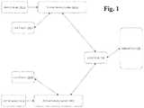
- FIG. 1is a simplified view illustrating how multiple workout sensing systems may communicate with other devices.
- FIG. 2shows one workout sensing system embodiment.
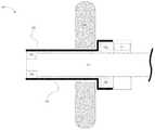
- FIG. 3Ashows one part of a device with a workout sensing system embedded.
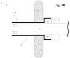
- FIG. 3Bshows another example of a device with workout sensing system embedded.
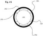
- FIG. 4Ais an end view of a device and force detector configuration.
- FIG. 4Banother end view of a device and force detector configuration.
- FIG. 4Canother end view of a device and force detector configuration.
- FIG. 5shows an exemplary process performed by the processor.
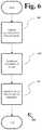
- FIG. 6shows an exemplary process performed by a force detector to compensate for device orientation.
- One purpose of the workout sensing systemis to provide data corresponding to a user's exercise that enables logging, tracking, and analysis of the user's exercise routine.
- a layer of softwarewhich may be artificial intelligence software, may then analyze a user's workout data and suggest workouts.
- FIG. 1shows an overview of how multiple workout sensing systems might communicate with other devices.
- the workout sensing system 150may be incorporated into a piece of strength training workout equipment at a gym, or some other workout device.
- the workout sensing system 150 of the present inventionmay be incorporated into a barbell, lat bar, or row bar.
- a usermay identify oneself to the workout sensing system 150 with a user identification device 151 .
- An example of a user identification device 151may be a near field communication enabled card, a smartphone, or a watch.
- the workout sensing system 150may then send workout data to a local display 153 and/or, optimally, to a local server 154 .
- Local display 153may be a user's smartphone, a tablet, or a display in the gym, or any other device, or it may not be present.
- Local server 154would collect data from multiple workout sensing systems 150 , then send it to a remote website/cloud 155 .
- the website/cloud 155would then analyze the data and display it to the user via a mobile app or web browser.
- the workout sensing system 150may be embedded in a piece of strength training workout equipment 203 .
- the workout sensing system 150consists of components which are electrically connected including detector(s) 202 , 209 , 210 , 211 , and 212 , a processor 206 , an internal display 205 and/or an external display 208 , and a data-logging device 213 .
- a battery 204may be used to power a processor 206 , detector(s) 202 , 209 , 210 , 211 , 212 and display 205 / 208 .
- the detector 209may be an accelerometer, an inertial measurement unit or other device well known in the art.
- the detector 202is for example a load cell, an array of multiple load cells, a strain gauge or an array of multiple strain gauges, or a pressure sensor.
- the display 205 / 208is for example a liquid crystal display or any other device to display data to the user.
- the detector 210is for example an inertial measurement unit, a lidar range finder, or an ultrasonic range finder.
- the detector 211is for example a real-time clock.
- the detector 212is for example a near field communication transceiver, WiFi or a BLUETOOTH communication transceiver, fingerprint scanner, or facial recognition detector.
- Multiple accelerometersmay be used (e.g., triaxial accelerometer). Where a remote display is used, a wireless communication transceiver may also be used.
- the data logging device 213may be a server, and may communicate with processor 206 via wireless communication.
- FIGS. 3A and 3Billustrate different exemplary embodiments of workout sensing system 150 in accordance with the present invention.
- FIG. 3Ais a cross-sectional side view of one part of an exemplary barbell embodiment 303 incorporating the workout sensing system 150 of the present invention.
- a weight 310is shown on barbell 303 (note, weight 310 is shown in FIG. 3A for illustrative purposes).
- the detectors 202are an exemplary part of a detector array. Each detector 202 is for example a load cell, a strain gauge, or a pressure sensor.
- the rest of workout sensing system 150may be embedded in within the sleeve of the barbell, location 311 , or another location on the bar.
- FIG. 3Bshows another exemplary barbell embodiment incorporating the workout sensing system 150 . It will be understood that this embodiment is similar to the embodiment in FIG. 3A to the extent not otherwise described herein. The two embodiments differ by incorporating a different implementation for force detection.
- the detectors 202detect load and may be a load cell, pressure sensor, strain gauge, or more specifically a spoke type load cell.
- a sleeve 309has a larger diameter on one end to accommodate detector 202 .
- the bar 303has a reduced diameter on the end to accommodate detector 202 .
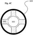
- FIGS. 4A, 4B, and 4Cshow one embodiment of the workout sensing system 150 described in 3 A.
- FIG. 4Ashows an end view of one part of an exemplary device 303 embedded with the workout sensing system 150 .
- the device 303may include a plurality of detectors.
- the device 303may include a group of four detectors 202 is shown. More or less detectors 202 may be incorporated in the system.
- Detectors 202may be arranged around the axis of bar 303 .
- Other examples of an array of detectors 202could include any quantity of detectors.
- Sleeve 309distributes load across detectors 202 .
- FIG. 4Bis the same view as FIG. 4A , however it shows another exemplary array of two detectors 202 .
- FIG. 4Cis the end view similar to FIG. 4A and FIG. 4B , however, this view corresponds to the device described in FIG. 3D .
- FIG. 4Cdescribes one example of detectors 202 .
- detectors 202are spoke type load cells.
- Processor 206samples multiple detectors in step 502 , processes the signal in step 503 , and transmits the data to a logging device or a display in step 504 , either embedded or remote.
- the following paragraphsdescribe specific exemplary processes that may be executed by processor 206 .
- the detector that is sampled in step 502is an accelerometer and therefore the physical metric is acceleration.
- the processor 206processes the physical metric to assess whether the metric indicates repetition of the device.
- repetition informationis displayed to the user.
- the detectors sampled in step 502are an array of load cells and an accelerometer.
- the physical metricsare therefore strain and acceleration.
- these physical metricswill be processed to determine the force vector exerted on the device. This is determined by calculating the acceleration vector of the device and the individual force vectors for each detector (detector configurations may be as shown in FIG. 3A , FIG. 4A , FIG. 4B , FIG. 4C or as shown in FIG. 3B ). By summing the components of each force vector that are parallel to the acceleration vector, the magnitude of the force vector may be determined then displayed in step 504 .
- process 500may determine and display the mass connected to the device.
- forcemay be determined as previously described.
- the detector that is sampled in step 502may be an accelerometer and therefore the physical metric is acceleration.
- This physical metricmay be processed in step 503 to determine the acceleration vector of the device.
- Weight connected to the devicescan be calculated by processing the force and acceleration vectors to determine mass. This step 503 may be, for example, dividing force by acceleration to determine mass, which may then be displayed in step 504 .
- process 500may determine the maximum displacement during a repetition.
- An accelerometermay be sampled in step 502 and therefore the physical metric is acceleration.
- this physical metricwill be processed to determine the maximum displacement during a repetition. This process may, for example, be a double integration.
- the maximum displacementmay then be displayed in step 504 .
- process 500may determine the average power over the span of a repetition.
- An accelerometermay be sampled in step 502 and therefore the physical metric is acceleration. Force may be calculated in step 503 as previously shown, along with the accelerometer data to determine average power over a repetition. This data may then be displayed in step 504 .
- process 500may determine the duration of a repetition or set of repetitions.
- a real time clockmay be sampled in step 702 , and therefore the physical metric is time. Duration of a repetition may then be determined in step 503 and displayed in step 504 .
- process 500may determine the identification of a user.
- the detectormay be a wireless transceiver, a fingerprint scanner, or a facial recognition module.
- the physical metric to be sampled in step 502would correspond to the detector utilized.
- the identification of the usermay then be determined in step 503 and displayed in step 504 .
- a detectormay use to determine the force placed on a device.
- This process 600compensates for the orientation of the device.
- step 601an array of load cells and an accelerometer are sampled.
- step 602the orientation of the device is determined.
- load on the barcan be determined.
- Load on each cellis determined by measuring the compression and tension forces in each spoke of the load cell. By summing up these forces, load on the cell is determined independent of the direction the load is applied, and is therefore independent of the orientation of the device. For example, a load cell measuring a 10 lb load from a set direction would output the same signal even if the load cell were rotated 45°. By averaging the outputs of detectors 202 , load on the device is determined.
- Coupledmeans the joining of two members directly or indirectly to one another. Such joining may be stationary (e.g., permanent) or moveable (e.g., removable or releasable). Such joining may be achieved with the two members or the two members and any additional intermediate members being integrally formed as a single unitary body with one another or with the two members or the two members and any additional intermediate members being attached to one another.
Landscapes
- Health & Medical Sciences (AREA)
- Physical Education & Sports Medicine (AREA)
- General Health & Medical Sciences (AREA)
- Life Sciences & Earth Sciences (AREA)
- Biophysics (AREA)
- Orthopedic Medicine & Surgery (AREA)
- Engineering & Computer Science (AREA)
- Multimedia (AREA)
- Human Computer Interaction (AREA)
- Software Systems (AREA)
- Databases & Information Systems (AREA)
- Computer Networks & Wireless Communication (AREA)
- Signal Processing (AREA)
- Measurement Of The Respiration, Hearing Ability, Form, And Blood Characteristics Of Living Organisms (AREA)
Abstract
Description
Claims (8)
Priority Applications (1)
| Application Number | Priority Date | Filing Date | Title |
|---|---|---|---|
| US15/690,459US10549154B2 (en) | 2016-09-01 | 2017-08-30 | Workout sensing system |
Applications Claiming Priority (2)
| Application Number | Priority Date | Filing Date | Title |
|---|---|---|---|
| US201662382387P | 2016-09-01 | 2016-09-01 | |
| US15/690,459US10549154B2 (en) | 2016-09-01 | 2017-08-30 | Workout sensing system |
Publications (2)
| Publication Number | Publication Date |
|---|---|
| US20180056127A1 US20180056127A1 (en) | 2018-03-01 |
| US10549154B2true US10549154B2 (en) | 2020-02-04 |
Family
ID=61240235
Family Applications (1)
| Application Number | Title | Priority Date | Filing Date |
|---|---|---|---|
| US15/690,459Expired - Fee RelatedUS10549154B2 (en) | 2016-09-01 | 2017-08-30 | Workout sensing system |
Country Status (1)
| Country | Link |
|---|---|
| US (1) | US10549154B2 (en) |
Cited By (4)
| Publication number | Priority date | Publication date | Assignee | Title |
|---|---|---|---|---|
| US11135477B1 (en)* | 2019-07-23 | 2021-10-05 | Philippos Kneknas | Exercise apparatus calibration system |
| US20220062685A1 (en)* | 2020-09-01 | 2022-03-03 | Icon Health & Fitness, Inc. | Detachable exercise tracking accessory |
| US11266878B2 (en)* | 2020-02-13 | 2022-03-08 | Frontier Fitness Llc | Analyzing sensor data associated with athletic equipment |
| US11717738B1 (en) | 2020-06-04 | 2023-08-08 | Daniel Martin Reader | Rowing machine handle media playback remote control and data collection system |
Families Citing this family (6)
| Publication number | Priority date | Publication date | Assignee | Title |
|---|---|---|---|---|
| US10463906B2 (en) | 2018-02-02 | 2019-11-05 | Jaxamo Ltd. | Exercise devices, systems, and methods |
| SE543713C2 (en)* | 2019-04-12 | 2021-06-29 | Eleiko Group Ab | Barbell with integrated sensor |
| US12066344B2 (en)* | 2020-06-19 | 2024-08-20 | Apple Inc. | Location of interest altitude and determining calibration points |
| US20220374806A1 (en)* | 2021-05-20 | 2022-11-24 | Chimney Hill Ventures LLC | System and method for tracking exercise equipment usage |
| US12179054B2 (en)* | 2021-09-20 | 2024-12-31 | Russell Breaux | Automatic spotter lift force calculator and display device and method of use |
| US20250229130A1 (en)* | 2024-01-11 | 2025-07-17 | Motorola Mobility Llc | Activity tracking for multiple users on a device |
Citations (27)
| Publication number | Priority date | Publication date | Assignee | Title |
|---|---|---|---|---|
| US4647038A (en)* | 1985-03-29 | 1987-03-03 | Lee E. Keith | Exerciser with strain gauges |
| US20030211916A1 (en)* | 2002-04-23 | 2003-11-13 | Capuano Patrick J. | Exercise parameters monitoring, recording and reporting system for free weight, weight stack, and sport-simulation exercise machines |
| US7163488B2 (en)* | 2003-04-16 | 2007-01-16 | Anders Douglas H | Free weight assistance and training device |
| US20070042866A1 (en)* | 2005-08-16 | 2007-02-22 | Steve Skilken | Calorie counter for weight lifting |
| US20080090703A1 (en) | 2006-10-14 | 2008-04-17 | Outland Research, Llc | Automated Personal Exercise Regimen Tracking Apparatus |
| US20080242513A1 (en)* | 2005-08-16 | 2008-10-02 | Max Rack, Inc. | Calorie counter for weight lifting |
| US20080287267A1 (en)* | 2005-11-30 | 2008-11-20 | Ellis Joseph K | Dual direction exercise treadmill for simulating a dragging or pulling action |
| US7455621B1 (en)* | 2004-08-12 | 2008-11-25 | Anthony Donald D | Free-weight exercise monitoring and feedback system and method |
| US7575537B2 (en)* | 2007-11-06 | 2009-08-18 | Fitness Tools, Llc | Dual direction exercise treadmill for simulating a dragging or pulling action with a user adjustable constant static weight resistance |
| US7666118B1 (en)* | 2004-08-12 | 2010-02-23 | Anthony Donald D | Free-weight exercise monitoring and feedback system and method |
| US20120165165A1 (en)* | 2010-12-22 | 2012-06-28 | Iankov Emilian H | Recording device for weightlifting |
| US20130288859A1 (en)* | 2012-04-30 | 2013-10-31 | Icon Health & Fitness, Inc. | Free Weight Monitoring System |
| US8602945B1 (en)* | 2010-03-22 | 2013-12-10 | Mark Gene Haubrich | Weightlifting laser light guidance tool |
| US20140235409A1 (en)* | 2012-11-13 | 2014-08-21 | D'Miles Salmon | System for monitoring fitness performance |
| US20150038303A1 (en)* | 2013-08-01 | 2015-02-05 | Daniel Adkins | Kinetic Dumbbell |
| US9135347B2 (en)* | 2013-12-18 | 2015-09-15 | Assess2Perform, LLC | Exercise tracking and analysis systems and related methods of use |
| US20150367162A1 (en)* | 2014-06-23 | 2015-12-24 | Peter A. Mueller | Weight adjustment by means of a ramp |
| US20160101320A1 (en)* | 2013-06-17 | 2016-04-14 | Softbank Corp. | Exercise equipment and exercise equipment set |
| US9318030B2 (en) | 2013-08-28 | 2016-04-19 | HAI Logan Gym, LLC | Personal training system and method |
| US9339692B2 (en)* | 2013-05-20 | 2016-05-17 | Rami Hashish | Exercise system for shifting an optimum length of peak muscle tension |
| US9381399B2 (en) | 2013-03-04 | 2016-07-05 | Cellco Partnership | Exercise recordation method and system |
| US20160310789A1 (en)* | 2014-04-25 | 2016-10-27 | Brandon C. Emerson | System and method for capturing exercise data |
| US20160346617A1 (en)* | 2014-01-30 | 2016-12-01 | Gymtrack Inc. | Systems, methods and devices for tracking workout related information |
| US9623285B1 (en)* | 2013-08-09 | 2017-04-18 | Mariano M Ruiz | Barbell level indicator |
| US20170128765A1 (en)* | 2014-11-10 | 2017-05-11 | Casey Garretson | Smart Barbell |
| US9789360B1 (en)* | 2015-02-24 | 2017-10-17 | Gary L. Schaffer | Apparatus for monitoring exercise efficiency and usage |
| US20180156657A1 (en)* | 2015-05-06 | 2018-06-07 | Ki Won Lee | Exercise measuring device, exercise apparatus having same, and exercise measuring method |
- 2017
- 2017-08-30USUS15/690,459patent/US10549154B2/ennot_activeExpired - Fee Related
Patent Citations (29)
| Publication number | Priority date | Publication date | Assignee | Title |
|---|---|---|---|---|
| US4647038A (en)* | 1985-03-29 | 1987-03-03 | Lee E. Keith | Exerciser with strain gauges |
| US20030211916A1 (en)* | 2002-04-23 | 2003-11-13 | Capuano Patrick J. | Exercise parameters monitoring, recording and reporting system for free weight, weight stack, and sport-simulation exercise machines |
| US7163488B2 (en)* | 2003-04-16 | 2007-01-16 | Anders Douglas H | Free weight assistance and training device |
| US7666118B1 (en)* | 2004-08-12 | 2010-02-23 | Anthony Donald D | Free-weight exercise monitoring and feedback system and method |
| US7455621B1 (en)* | 2004-08-12 | 2008-11-25 | Anthony Donald D | Free-weight exercise monitoring and feedback system and method |
| US20070042866A1 (en)* | 2005-08-16 | 2007-02-22 | Steve Skilken | Calorie counter for weight lifting |
| US20080242513A1 (en)* | 2005-08-16 | 2008-10-02 | Max Rack, Inc. | Calorie counter for weight lifting |
| US20080287267A1 (en)* | 2005-11-30 | 2008-11-20 | Ellis Joseph K | Dual direction exercise treadmill for simulating a dragging or pulling action |
| US20080090703A1 (en) | 2006-10-14 | 2008-04-17 | Outland Research, Llc | Automated Personal Exercise Regimen Tracking Apparatus |
| US7575537B2 (en)* | 2007-11-06 | 2009-08-18 | Fitness Tools, Llc | Dual direction exercise treadmill for simulating a dragging or pulling action with a user adjustable constant static weight resistance |
| US8602945B1 (en)* | 2010-03-22 | 2013-12-10 | Mark Gene Haubrich | Weightlifting laser light guidance tool |
| US20120165165A1 (en)* | 2010-12-22 | 2012-06-28 | Iankov Emilian H | Recording device for weightlifting |
| US20130288859A1 (en)* | 2012-04-30 | 2013-10-31 | Icon Health & Fitness, Inc. | Free Weight Monitoring System |
| US9126072B2 (en) | 2012-04-30 | 2015-09-08 | Icon Health & Fitness, Inc. | Free weight monitoring system |
| US20140235409A1 (en)* | 2012-11-13 | 2014-08-21 | D'Miles Salmon | System for monitoring fitness performance |
| US9468793B2 (en) | 2012-11-13 | 2016-10-18 | D'Miles Salmon | System for monitoring fitness performance |
| US9381399B2 (en) | 2013-03-04 | 2016-07-05 | Cellco Partnership | Exercise recordation method and system |
| US9339692B2 (en)* | 2013-05-20 | 2016-05-17 | Rami Hashish | Exercise system for shifting an optimum length of peak muscle tension |
| US20160101320A1 (en)* | 2013-06-17 | 2016-04-14 | Softbank Corp. | Exercise equipment and exercise equipment set |
| US20150038303A1 (en)* | 2013-08-01 | 2015-02-05 | Daniel Adkins | Kinetic Dumbbell |
| US9623285B1 (en)* | 2013-08-09 | 2017-04-18 | Mariano M Ruiz | Barbell level indicator |
| US9318030B2 (en) | 2013-08-28 | 2016-04-19 | HAI Logan Gym, LLC | Personal training system and method |
| US9135347B2 (en)* | 2013-12-18 | 2015-09-15 | Assess2Perform, LLC | Exercise tracking and analysis systems and related methods of use |
| US20160346617A1 (en)* | 2014-01-30 | 2016-12-01 | Gymtrack Inc. | Systems, methods and devices for tracking workout related information |
| US20160310789A1 (en)* | 2014-04-25 | 2016-10-27 | Brandon C. Emerson | System and method for capturing exercise data |
| US20150367162A1 (en)* | 2014-06-23 | 2015-12-24 | Peter A. Mueller | Weight adjustment by means of a ramp |
| US20170128765A1 (en)* | 2014-11-10 | 2017-05-11 | Casey Garretson | Smart Barbell |
| US9789360B1 (en)* | 2015-02-24 | 2017-10-17 | Gary L. Schaffer | Apparatus for monitoring exercise efficiency and usage |
| US20180156657A1 (en)* | 2015-05-06 | 2018-06-07 | Ki Won Lee | Exercise measuring device, exercise apparatus having same, and exercise measuring method |
Cited By (4)
| Publication number | Priority date | Publication date | Assignee | Title |
|---|---|---|---|---|
| US11135477B1 (en)* | 2019-07-23 | 2021-10-05 | Philippos Kneknas | Exercise apparatus calibration system |
| US11266878B2 (en)* | 2020-02-13 | 2022-03-08 | Frontier Fitness Llc | Analyzing sensor data associated with athletic equipment |
| US11717738B1 (en) | 2020-06-04 | 2023-08-08 | Daniel Martin Reader | Rowing machine handle media playback remote control and data collection system |
| US20220062685A1 (en)* | 2020-09-01 | 2022-03-03 | Icon Health & Fitness, Inc. | Detachable exercise tracking accessory |
Also Published As
| Publication number | Publication date |
|---|---|
| US20180056127A1 (en) | 2018-03-01 |
Similar Documents
| Publication | Publication Date | Title |
|---|---|---|
| US10549154B2 (en) | Workout sensing system | |
| US10213648B2 (en) | Method and apparatus for measuring power output of exercise | |
| US10740650B2 (en) | Systems and methods for non-contact tracking and analysis of exercise | |
| US20200289890A1 (en) | Intelligent Exercise or Therapy Apparatus and Method | |
| CN107961523B (en) | Human body training system and intelligent fitness system based on heart rate detection | |
| US11117018B2 (en) | System for measuring, monitoring and displaying physical parameters of exercises on selectorized fitness machines | |
| US20190143174A1 (en) | Motion training guide system based on wearable sensor and method thereof | |
| US20170216665A1 (en) | System for Measuring and Reporting Weight-Training Performance Metrics | |
| US10970661B2 (en) | System and method for monitoring motion and orientation patterns associated to physical activities of users | |
| US20170209743A1 (en) | System and method for linking oscillating movements of exercise equipment to a user of the exercise equipment in a database | |
| US11266878B2 (en) | Analyzing sensor data associated with athletic equipment | |
| KR101651429B1 (en) | Fitness monitoring system | |
| TWI679557B (en) | Adaptive sport posture sensing system and method | |
| Hribernik et al. | Sensor based agility assessment in sport | |
| CN105288957A (en) | Physical ability comprehensive training apparatus and evaluation system thereof | |
| KR20160002585A (en) | Golf Analyzer and Management System | |
| KR101277177B1 (en) | apparatus and method assisting exercise,system for managing exercise ability of the members | |
| KR20180000581A (en) | sports action coating apparatus and method therefor | |
| KR20160121460A (en) | Fitness monitoring system | |
| Shell et al. | Is a head-worn inertial sensor a valid tool to monitor swimming? | |
| EP3357548B1 (en) | Teaching compatibility determining device, teaching compatibility determining program and recording medium for storing said program | |
| US20250025748A1 (en) | Apparatus for tracking kinesthetics | |
| Fıdan et al. | Design and development of an upper extremity performance analysis system for combat sports | |
| US20060053897A1 (en) | Measuring device | |
| KR20180072235A (en) | Game method based on body activity and user terminal |
Legal Events
| Date | Code | Title | Description |
|---|---|---|---|
| FEPP | Fee payment procedure | Free format text:ENTITY STATUS SET TO UNDISCOUNTED (ORIGINAL EVENT CODE: BIG.); ENTITY STATUS OF PATENT OWNER: MICROENTITY | |
| FEPP | Fee payment procedure | Free format text:ENTITY STATUS SET TO MICRO (ORIGINAL EVENT CODE: MICR); ENTITY STATUS OF PATENT OWNER: MICROENTITY Free format text:ENTITY STATUS SET TO UNDISCOUNTED (ORIGINAL EVENT CODE: BIG.); ENTITY STATUS OF PATENT OWNER: MICROENTITY Free format text:ENTITY STATUS SET TO SMALL (ORIGINAL EVENT CODE: SMAL); ENTITY STATUS OF PATENT OWNER: MICROENTITY | |
| FEPP | Fee payment procedure | Free format text:ENTITY STATUS SET TO MICRO (ORIGINAL EVENT CODE: MICR); ENTITY STATUS OF PATENT OWNER: MICROENTITY | |
| STPP | Information on status: patent application and granting procedure in general | Free format text:NON FINAL ACTION MAILED | |
| STPP | Information on status: patent application and granting procedure in general | Free format text:RESPONSE TO NON-FINAL OFFICE ACTION ENTERED AND FORWARDED TO EXAMINER | |
| STPP | Information on status: patent application and granting procedure in general | Free format text:NOTICE OF ALLOWANCE MAILED -- APPLICATION RECEIVED IN OFFICE OF PUBLICATIONS | |
| STPP | Information on status: patent application and granting procedure in general | Free format text:PUBLICATIONS -- ISSUE FEE PAYMENT VERIFIED | |
| AS | Assignment | Owner name:F0RZAMETRIX, LLC, MICHIGAN Free format text:ASSIGNMENT OF ASSIGNORS INTEREST;ASSIGNOR:MCINTYRE, CORINA;REEL/FRAME:051553/0125 Effective date:20191217 Owner name:F0RZAMETRIX, LLC, MICHIGAN Free format text:ASSIGNMENT OF ASSIGNORS INTEREST;ASSIGNOR:DEN HOLLANDER, BRYAN;REEL/FRAME:051553/0065 Effective date:20191217 | |
| STCF | Information on status: patent grant | Free format text:PATENTED CASE | |
| FEPP | Fee payment procedure | Free format text:MAINTENANCE FEE REMINDER MAILED (ORIGINAL EVENT CODE: REM.); ENTITY STATUS OF PATENT OWNER: MICROENTITY | |
| LAPS | Lapse for failure to pay maintenance fees | Free format text:PATENT EXPIRED FOR FAILURE TO PAY MAINTENANCE FEES (ORIGINAL EVENT CODE: EXP.); ENTITY STATUS OF PATENT OWNER: MICROENTITY | |
| STCH | Information on status: patent discontinuation | Free format text:PATENT EXPIRED DUE TO NONPAYMENT OF MAINTENANCE FEES UNDER 37 CFR 1.362 | |
| FP | Lapsed due to failure to pay maintenance fee | Effective date:20240204 |