US10548738B2 - Expandable interbody implant - Google Patents
Expandable interbody implantDownload PDFInfo
- Publication number
- US10548738B2 US10548738B2US15/481,854US201715481854AUS10548738B2US 10548738 B2US10548738 B2US 10548738B2US 201715481854 AUS201715481854 AUS 201715481854AUS 10548738 B2US10548738 B2US 10548738B2
- Authority
- US
- United States
- Prior art keywords
- implant
- configuration
- locking element
- locking
- pinion
- Prior art date
- Legal status (The legal status is an assumption and is not a legal conclusion. Google has not performed a legal analysis and makes no representation as to the accuracy of the status listed.)
- Active, expires
Links
Images


Classifications
- A—HUMAN NECESSITIES
- A61—MEDICAL OR VETERINARY SCIENCE; HYGIENE
- A61F—FILTERS IMPLANTABLE INTO BLOOD VESSELS; PROSTHESES; DEVICES PROVIDING PATENCY TO, OR PREVENTING COLLAPSING OF, TUBULAR STRUCTURES OF THE BODY, e.g. STENTS; ORTHOPAEDIC, NURSING OR CONTRACEPTIVE DEVICES; FOMENTATION; TREATMENT OR PROTECTION OF EYES OR EARS; BANDAGES, DRESSINGS OR ABSORBENT PADS; FIRST-AID KITS
- A61F2/00—Filters implantable into blood vessels; Prostheses, i.e. artificial substitutes or replacements for parts of the body; Appliances for connecting them with the body; Devices providing patency to, or preventing collapsing of, tubular structures of the body, e.g. stents
- A61F2/02—Prostheses implantable into the body
- A61F2/30—Joints
- A61F2/44—Joints for the spine, e.g. vertebrae, spinal discs
- A61F2/442—Intervertebral or spinal discs, e.g. resilient
- A61F2/4425—Intervertebral or spinal discs, e.g. resilient made of articulated components
- A—HUMAN NECESSITIES
- A61—MEDICAL OR VETERINARY SCIENCE; HYGIENE
- A61F—FILTERS IMPLANTABLE INTO BLOOD VESSELS; PROSTHESES; DEVICES PROVIDING PATENCY TO, OR PREVENTING COLLAPSING OF, TUBULAR STRUCTURES OF THE BODY, e.g. STENTS; ORTHOPAEDIC, NURSING OR CONTRACEPTIVE DEVICES; FOMENTATION; TREATMENT OR PROTECTION OF EYES OR EARS; BANDAGES, DRESSINGS OR ABSORBENT PADS; FIRST-AID KITS
- A61F2/00—Filters implantable into blood vessels; Prostheses, i.e. artificial substitutes or replacements for parts of the body; Appliances for connecting them with the body; Devices providing patency to, or preventing collapsing of, tubular structures of the body, e.g. stents
- A61F2/02—Prostheses implantable into the body
- A61F2/30—Joints
- A61F2/44—Joints for the spine, e.g. vertebrae, spinal discs
- A61F2/4455—Joints for the spine, e.g. vertebrae, spinal discs for the fusion of spinal bodies, e.g. intervertebral fusion of adjacent spinal bodies, e.g. fusion cages
- A61F2/447—Joints for the spine, e.g. vertebrae, spinal discs for the fusion of spinal bodies, e.g. intervertebral fusion of adjacent spinal bodies, e.g. fusion cages substantially parallelepipedal, e.g. having a rectangular or trapezoidal cross-section
- A—HUMAN NECESSITIES
- A61—MEDICAL OR VETERINARY SCIENCE; HYGIENE
- A61F—FILTERS IMPLANTABLE INTO BLOOD VESSELS; PROSTHESES; DEVICES PROVIDING PATENCY TO, OR PREVENTING COLLAPSING OF, TUBULAR STRUCTURES OF THE BODY, e.g. STENTS; ORTHOPAEDIC, NURSING OR CONTRACEPTIVE DEVICES; FOMENTATION; TREATMENT OR PROTECTION OF EYES OR EARS; BANDAGES, DRESSINGS OR ABSORBENT PADS; FIRST-AID KITS
- A61F2/00—Filters implantable into blood vessels; Prostheses, i.e. artificial substitutes or replacements for parts of the body; Appliances for connecting them with the body; Devices providing patency to, or preventing collapsing of, tubular structures of the body, e.g. stents
- A61F2/02—Prostheses implantable into the body
- A61F2/30—Joints
- A61F2002/30001—Additional features of subject-matter classified in A61F2/28, A61F2/30 and subgroups thereof
- A61F2002/30316—The prosthesis having different structural features at different locations within the same prosthesis; Connections between prosthetic parts; Special structural features of bone or joint prostheses not otherwise provided for
- A61F2002/30329—Connections or couplings between prosthetic parts, e.g. between modular parts; Connecting elements
- A61F2002/30476—Connections or couplings between prosthetic parts, e.g. between modular parts; Connecting elements locked by an additional locking mechanism
- A61F2002/30482—Connections or couplings between prosthetic parts, e.g. between modular parts; Connecting elements locked by an additional locking mechanism using a locking cam
- A—HUMAN NECESSITIES
- A61—MEDICAL OR VETERINARY SCIENCE; HYGIENE
- A61F—FILTERS IMPLANTABLE INTO BLOOD VESSELS; PROSTHESES; DEVICES PROVIDING PATENCY TO, OR PREVENTING COLLAPSING OF, TUBULAR STRUCTURES OF THE BODY, e.g. STENTS; ORTHOPAEDIC, NURSING OR CONTRACEPTIVE DEVICES; FOMENTATION; TREATMENT OR PROTECTION OF EYES OR EARS; BANDAGES, DRESSINGS OR ABSORBENT PADS; FIRST-AID KITS
- A61F2/00—Filters implantable into blood vessels; Prostheses, i.e. artificial substitutes or replacements for parts of the body; Appliances for connecting them with the body; Devices providing patency to, or preventing collapsing of, tubular structures of the body, e.g. stents
- A61F2/02—Prostheses implantable into the body
- A61F2/30—Joints
- A61F2002/30001—Additional features of subject-matter classified in A61F2/28, A61F2/30 and subgroups thereof
- A61F2002/30316—The prosthesis having different structural features at different locations within the same prosthesis; Connections between prosthetic parts; Special structural features of bone or joint prostheses not otherwise provided for
- A61F2002/30329—Connections or couplings between prosthetic parts, e.g. between modular parts; Connecting elements
- A61F2002/30518—Connections or couplings between prosthetic parts, e.g. between modular parts; Connecting elements with possibility of relative movement between the prosthetic parts
- A61F2002/30523—Connections or couplings between prosthetic parts, e.g. between modular parts; Connecting elements with possibility of relative movement between the prosthetic parts by means of meshing gear teeth
- A—HUMAN NECESSITIES
- A61—MEDICAL OR VETERINARY SCIENCE; HYGIENE
- A61F—FILTERS IMPLANTABLE INTO BLOOD VESSELS; PROSTHESES; DEVICES PROVIDING PATENCY TO, OR PREVENTING COLLAPSING OF, TUBULAR STRUCTURES OF THE BODY, e.g. STENTS; ORTHOPAEDIC, NURSING OR CONTRACEPTIVE DEVICES; FOMENTATION; TREATMENT OR PROTECTION OF EYES OR EARS; BANDAGES, DRESSINGS OR ABSORBENT PADS; FIRST-AID KITS
- A61F2/00—Filters implantable into blood vessels; Prostheses, i.e. artificial substitutes or replacements for parts of the body; Appliances for connecting them with the body; Devices providing patency to, or preventing collapsing of, tubular structures of the body, e.g. stents
- A61F2/02—Prostheses implantable into the body
- A61F2/30—Joints
- A61F2002/30001—Additional features of subject-matter classified in A61F2/28, A61F2/30 and subgroups thereof
- A61F2002/30316—The prosthesis having different structural features at different locations within the same prosthesis; Connections between prosthetic parts; Special structural features of bone or joint prostheses not otherwise provided for
- A61F2002/30535—Special structural features of bone or joint prostheses not otherwise provided for
- A61F2002/30537—Special structural features of bone or joint prostheses not otherwise provided for adjustable
- A61F2002/30556—Special structural features of bone or joint prostheses not otherwise provided for adjustable for adjusting thickness
- A—HUMAN NECESSITIES
- A61—MEDICAL OR VETERINARY SCIENCE; HYGIENE
- A61F—FILTERS IMPLANTABLE INTO BLOOD VESSELS; PROSTHESES; DEVICES PROVIDING PATENCY TO, OR PREVENTING COLLAPSING OF, TUBULAR STRUCTURES OF THE BODY, e.g. STENTS; ORTHOPAEDIC, NURSING OR CONTRACEPTIVE DEVICES; FOMENTATION; TREATMENT OR PROTECTION OF EYES OR EARS; BANDAGES, DRESSINGS OR ABSORBENT PADS; FIRST-AID KITS
- A61F2/00—Filters implantable into blood vessels; Prostheses, i.e. artificial substitutes or replacements for parts of the body; Appliances for connecting them with the body; Devices providing patency to, or preventing collapsing of, tubular structures of the body, e.g. stents
- A61F2/02—Prostheses implantable into the body
- A61F2/30—Joints
- A61F2002/30001—Additional features of subject-matter classified in A61F2/28, A61F2/30 and subgroups thereof
- A61F2002/30316—The prosthesis having different structural features at different locations within the same prosthesis; Connections between prosthetic parts; Special structural features of bone or joint prostheses not otherwise provided for
- A61F2002/30535—Special structural features of bone or joint prostheses not otherwise provided for
- A61F2002/30565—Special structural features of bone or joint prostheses not otherwise provided for having spring elements
- A61F2002/30566—Helical springs
- A—HUMAN NECESSITIES
- A61—MEDICAL OR VETERINARY SCIENCE; HYGIENE
- A61F—FILTERS IMPLANTABLE INTO BLOOD VESSELS; PROSTHESES; DEVICES PROVIDING PATENCY TO, OR PREVENTING COLLAPSING OF, TUBULAR STRUCTURES OF THE BODY, e.g. STENTS; ORTHOPAEDIC, NURSING OR CONTRACEPTIVE DEVICES; FOMENTATION; TREATMENT OR PROTECTION OF EYES OR EARS; BANDAGES, DRESSINGS OR ABSORBENT PADS; FIRST-AID KITS
- A61F2/00—Filters implantable into blood vessels; Prostheses, i.e. artificial substitutes or replacements for parts of the body; Appliances for connecting them with the body; Devices providing patency to, or preventing collapsing of, tubular structures of the body, e.g. stents
- A61F2/02—Prostheses implantable into the body
- A61F2/30—Joints
- A61F2/44—Joints for the spine, e.g. vertebrae, spinal discs
- A61F2/442—Intervertebral or spinal discs, e.g. resilient
- A61F2/4425—Intervertebral or spinal discs, e.g. resilient made of articulated components
- A61F2002/443—Intervertebral or spinal discs, e.g. resilient made of articulated components having two transversal endplates and at least one intermediate component
- A—HUMAN NECESSITIES
- A61—MEDICAL OR VETERINARY SCIENCE; HYGIENE
- A61F—FILTERS IMPLANTABLE INTO BLOOD VESSELS; PROSTHESES; DEVICES PROVIDING PATENCY TO, OR PREVENTING COLLAPSING OF, TUBULAR STRUCTURES OF THE BODY, e.g. STENTS; ORTHOPAEDIC, NURSING OR CONTRACEPTIVE DEVICES; FOMENTATION; TREATMENT OR PROTECTION OF EYES OR EARS; BANDAGES, DRESSINGS OR ABSORBENT PADS; FIRST-AID KITS
- A61F2/00—Filters implantable into blood vessels; Prostheses, i.e. artificial substitutes or replacements for parts of the body; Appliances for connecting them with the body; Devices providing patency to, or preventing collapsing of, tubular structures of the body, e.g. stents
- A61F2/02—Prostheses implantable into the body
- A61F2/30—Joints
- A61F2/46—Special tools for implanting artificial joints
- A61F2002/4688—Special tools for implanting artificial joints having operating or control means
- A61F2002/4692—Special tools for implanting artificial joints having operating or control means fluid
- A61F2002/4693—Special tools for implanting artificial joints having operating or control means fluid hydraulic
Definitions
- Intervertebral implantsare commonly used in spinal surgery, such as in interbody fusion procedures, in which an implant (e.g., a spacer or cage) is placed in the disc space between two vertebrae to be fused together. At least a portion of the disc is typically removed before the implant is positioned in the intervertebral space, and the implant may be supplemented with bone graft material to promote fusion of the vertebrae. Interbody fusion procedures may also be performed in conjunction with other types of fixation, such as pedicle screw fixation, to provide additional stability, particularly while the vertebrae fuse together.
- an implante.g., a spacer or cage
- fixationsuch as pedicle screw fixation
- Different interbody fusion procedurescan be distinguished by their location along the spine (e.g., in the cervical, thoracic, or lumbar regions); by the type of implant used; and by the surgical approach to the intervertebral space, in which different surgical approaches often imply different structural characteristics of the implant or implants used.
- Different surgical approaches to the spineinclude anterior, posterior, and lateral.
- Examples of interbody fusion techniques performed along a posterior approachinclude posterior lumbar interbody fusion (PLIF) and transforaminal lumbar interbody fusion (TLIF).
- PLIF techniquestypically include positioning two intervertebral implants into the intervertebral space along a posterior to anterior direction, with one implant being positioned towards the left side of the spine and one implant being positioned towards the right side of the spine.
- TLIF techniquestypically have a straight shape, in that they extend along a central axis.
- TLIF techniquestypically include positioning one intervertebral implant into the intervertebral space (often towards the anterior portion of the intervertebral space) from the posterior of the patient, but the spine is approached on one side from a more lateral position than in PLIF techniques.
- the implants used in such TLIF techniquesare often curved, such that they have an overall kidney bean-like shape.
- intervertebral implantsinclude expandable implants. Such implants often have an initially contracted configuration, such that they have a low profile in the superior-inferior direction, in order to ease insertion into the intervertebral space. Such expandable implants can then be expanded in the superior-inferior direction after implantation, so as to securely engage and stabilize the vertebrae on both sides of the intervertebral space. Examples of such expandable intervertebral implants are disclosed in U.S. Pat. No. 8,992,620 (“the '620 Patent”), which is hereby incorporated by reference herein as if fully set forth herein. Expandable intervertebral implants having certain similar features to those in the '620 Patent are disclosed herein, and therefore some similar nomenclature is used herein for clarity and consistency.
- Expandable interbody implantsin accordance with aspects of the invention include opposing first and second surfaces for engaging respective vertebral bodies on each side of an intervertebral space. When the implants are expanded from a contracted configuration to an expanded configuration, the first and second surfaces are moved apart from one another.
- a locking systemmay be provided for restraining contraction of the implant.
- the locking systemmay have a locked configuration, in which the first and second surfaces are prevented from moving back towards the contracted configuration, and the locking system may have an unlocked configuration, in which the first and second surfaces are permitted to move back towards the contracted configuration.
- the locking systemmay be controlled by rotation of one or more pinions.
- the pinionsmay, in turn, be controlled by linear movement of a rack.
- the rackmay be configured so as to bias the locking system towards the locked configuration.
- Other aspects of the inventionmay include a stop for constraining the maximum expansion of the implant.
- a spinal implant for placement between first and second vertebral bodiesincludes first and second members having respective first and second surfaces for engaging the respective vertebral bodies.
- the first and second surfacesmay be on opposing sides of the implant to engage the respective vertebral bodies on each side of an intervertebral space.
- the implantmay include at least one extendable support element and a locking system.
- the extendable support elementmay have a contracted configuration and at least one extended configuration.
- the contracted configurationmay facilitate deployment of the implant between the first and second vertebral bodies.
- the first and second membersIn the extended configuration, the first and second members may extend away from one another so that the first and second surfaces are positioned further apart from one another than in the contracted configuration.
- the locking systemmay comprise at least one locking element movable between a locked configuration and an unlocked configuration.
- the locking elementmay prevent movement of the extendable support element towards the contracted configuration when the locking element is in the locked configuration, and the locking element may permit movement of the extendable support element towards the contracted configuration when the locking element is in the unlocked configuration.
- the locking elementmay also include a pinion, such that movement of the locking element between the locked and unlocked configuration is actuated by rotation of the pinion.
- the spinal implantmay include a linear rack for rotating the pinion.
- the linear rackmay move linearly within a channel that supplies a fluid for extending the extendable support element.
- the linear rackmay be biased so as to move the locking element towards the locked configuration.
- the linear rackmay be biased by a linear spring.
- the locking systemmay further include a second locking element having a second pinion.
- the second locking elementmay be movable between a locked configuration and an unlocked configuration by rotation of the second pinion.
- the second locking elementmay prevent movement of a second one of the extendable support elements towards the contracted configuration when the second locking element is in the locked configuration, and the second locking element may permit movement of the second extendable support element towards the contracted configuration when the second locking element is in the unlocked configuration.
- a linear rackmay be engaged with the pinion and the second pinion for simultaneously rotating the pinion and the second pinion.
- the extendable support elementmay be configured to be extended by a fluid.
- the extendable support elementmay include a piston slidably received within a cylinder.
- the locking elementmay be received within the cylinder.
- the locking systemmay include a plurality of inter-engaging locking elements, including an upper lock support member and a lower lock support member, and the locking element may be one of the upper and lower lock support members.
- the upper lock support membermay have a multi-stepped support surface
- the lower lock support systemmay have a multi-stepped support surface configured to move into engagement with the multi-stepped support surface of the upper lock support member in the locked configuration.
- the locking elementmay be the lower lock support member, which may be rotatable relative to the upper lock support member between the locked and unlocked configurations in response to rotation of the pinion.
- the lower lock support membermay be rotatable relative to the upper lock support member about an axle rigidly connected to one of the first and second members.
- the extendable support elementmay include a piston slidably received within a cylinder.
- the upper lock support membermay be disposed within the piston and the lower lock support member may be rotatably received within the cylinder.
- one of the first and second membersmay define a slot extending along an extension direction, and the other of the first and second members may include a projection received within the slot.
- the projectionmay prevent further extension of the first and second members away from one another when the projection abuts an end of the slot.
- the extendable support elementmay comprise a first extendable support element and a second extendable support element, such that the projection and the slot are positioned between the first and second extendable support elements.
- the implantmay have a curved, kidney bean-like shape.
- the implantmay have a straight shape along its central longitudinal axis.
- a spinal implant for placement between first and second vertebral bodiesincludes first and second members having respective first and second surfaces for engaging the respective vertebral bodies.
- the first and second surfacesmay be on opposing sides of the implant to engage the respective vertebral bodies on each side of an intervertebral space.
- the implantmay include at least one extendable support element and a locking system.
- the extendable support elementmay have a contracted configuration and at least one extended configuration.
- the contracted configurationmay facilitate deployment of the implant between the first and second vertebral bodies.
- the first and second membersIn the extended configuration, may extend away from one another along an extension direction so that the first and second surfaces are positioned further apart from one another than in the contracted configuration.
- One of the first and second membersmay further define a slot extending along the extension direction, and the other of the first and second members may include a projection received within the slot.
- the projectiondesirably prevents further extension of the first and second members away from one another when the projection abuts an end of the slot.
- the slotmay be defined within the first member and the projection may be provided on the second member.
- the projectionmay include a pin removably secured within an opening of the second member.
- FIG. 1is an exploded, perspective view of an implant in accordance with one embodiment of the present invention.
- FIG. 2Ais a perspective view of the embodiment of FIG. 1 in a contracted configuration.
- FIG. 2Bis a side elevation view of the embodiment of FIG. 1 in a contracted configuration.
- FIG. 3Ais a perspective view of the embodiment of FIG. 1 in an extended configuration.
- FIG. 3Bis a side elevation view of the embodiment of FIG. 1 in an extended configuration.
- FIG. 4Ais a cross-sectional, plan view of the embodiment of FIG. 1 in a contracted configuration.
- FIG. 4Bis a cross-sectional, plan view of the embodiment of FIG. 1 in an extended configuration.
- FIG. 5Ais a cross-sectional, side elevation view of the embodiment of FIG. 1 in a contracted configuration.
- FIG. 5Bis a cross-sectional, side elevation view of the embodiment of FIG. 1 in an extended configuration.
- FIG. 6is a cross-sectional, side elevation view of the embodiment of FIG. 1 , showing different features of the implant.
- FIG. 7Ais a cross-sectional, side elevation view of the embodiment of FIG. 1 in a contracted configuration.
- FIG. 7Bis a cross-sectional, side elevation view of the embodiment of FIG. 1 in an extended configuration.
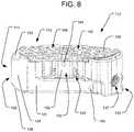
- FIG. 8is a perspective view of an embodiment in accordance with another embodiment of the present invention in a contracted configuration.
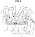
- FIG. 9is a cross-sectional, plan view of the embodiment of FIG. 8 .
- FIG. 10is a side elevation view of the embodiment of FIG. 8 in an extended configuration.
- FIG. 11is a rear elevation view of the embodiment of FIG. 8 in a contracted configuration.
- FIG. 12Ais a top plan view of the embodiment of FIG. 8 .
- FIG. 12Bis a bottom plan view of the embodiment of FIG. 8 .
- FIG. 13Ais a perspective view of an embodiment in accordance with another embodiment of the present invention in a contracted configuration.
- FIG. 13Bis a perspective view of the embodiment of FIG. 13A in a contracted configuration, taken from a different angle.
- FIG. 14is a cross-sectional, plan view of the embodiment of FIG. 13A .
- FIG. 15Ais a side elevation view of the embodiment of FIG. 13A in an extended configuration.
- FIG. 15Bis a side elevation view of the embodiment of FIG. 13A in a contracted configuration.
- FIG. 16is a rear elevation view of the embodiment of FIG. 13A in a contracted configuration.
- FIG. 17Ais a top plan view of the embodiment of FIG. 13A .
- FIG. 17Bis a bottom plan view of the embodiment of FIG. 13A .
- FIGS. 1-7Billustrate an embodiment of an intervertebral implant 10 in accordance with the present invention.
- the implant 10generally includes a housing 11 and a top end plate 13 , and the housing 11 defines an interior cavity 15 within it.
- the top end plate 13may include an opening 6 within it, bounded by connecting members or struts 44 extending between the left and right sides of the top end plate 13 , which opening 6 communicates with the interior cavity 15 .
- the bottom 12 of the housing 11may include one or more openings (not shown) within it, which openings communicate with the interior cavity 15 .
- An example of such an opening 107 in the bottom of the housingis illustrated in the embodiment of the implant 110 illustrated in FIG. 12B .
- the bottom 12 of the housing 11has a bottom end surface 8 and the top end plate 13 has a top end surface 9 .
- the top end plate 13is movably connected to the housing 11 on the opposite side of the housing 11 from the bottom end surface 8 .
- the top and bottom end surfacesare the bone engaging surfaces of the implant, for engaging vertebrae above and below the implant when placed in the patient.
- the implant 10is expandable by translating the top end plate 13 away from the housing 11 , from the contracted configuration illustrated in FIGS. 2A-B to the extended configuration illustrated in FIGS. 3A-B .
- the implant 10includes a pair of extendable support elements in the form of pistons 22 attached to the underside of the top end plate 13 , which pistons 22 are slidably received within a corresponding pair of cylinders 16 defined within the housing 11 .
- the sliding of the pistons 22 along the cylinders 16results in the translation of the top end plate 13 so as to expand the implant 10 , as discussed above.
- the pistons 22 and cylinders 16may operate as part of a hydraulic system, in which the sliding of the pistons 22 away from the bottoms of the cylinders is driven by pressurized fluid within the cylinders 16 , as discussed below and in the '620 Patent.
- Seal members 23which may be in the form of o-rings, are positioned so as to seal the sliding interface between the cylinders 16 and the respective pistons 22 , in order to prevent the pressurized fluid from escaping through that interface.
- the seal members 23may be seated within corresponding grooves 45 defined in the outer surfaces of the cylinders 16 .
- the seal members 23may be mounted on the pistons 22 so that the seal members 23 slide with the pistons 22 within the cylinders 16 , as disclosed in certain embodiments of the '620 Patent.
- the implant 10also includes a locking system to lock the position of the top end plate 13 by preventing the top end plate 13 from translating back towards the housing 11 .
- That locking systemmay include multiple inter-engaging locking elements.
- the implant 10may include a pair of lower lock supports 20 positioned within the housing 11 and a corresponding pair of upper lock supports 17 (see FIG. 6 ) connected to the underside of the top end plate 13 .
- the upper lock supports 17may be positioned within the respective pistons 22 , and they may be fixed with respect to the pistons 22 and the top end plate 13 .
- each of the upper lock supports 17may be integrally formed with either or both of the top end plate 13 and the respective piston 22 .
- the upper lock supports 17have tiered, multi-stepped lower support surfaces 18 and vertical risers or alignment faces 46 , much like an inverted spiral staircase.
- the lower lock supports 20which may be positioned within the respective pistons 22 , similarly have tiered, multi-stepped upper support surfaces 21 and vertical risers or alignment faces 47 , much like an upright spiral staircase.
- the support surfaces 18 of the upper lock supports 17engage the support surfaces 21 of the lower lock supports 20
- the alignment faces 46 of the upper lock supportsare configured to engage the alignment faces 47 of the lower lock supports 20 .
- the stepped support surfaces of both the upper and lower lock supportsform locking surfaces of the locking elements.
- the engagement of the multi-stepped lower support surfaces 18 of the upper lock supports 17 with the multi-stepped upper support surfaces 21 of the lower lock supports 20prevents the top end plate 13 from translating back towards the housing 11 , as discussed in more detail below and in the '620 Patent.
- the tiered, multiple steps of the upper and lower lock supportsallow the implant 10 to be locked at several different expanded heights.
- the underside of the stepped support surfaces 18 of the upper lock support 17may be provided with increasing riser height (alignment faces 46 ) in the upward direction to provide smaller incremental expansion near the end of the piston expansion.
- the stepped support surfaces 21 of the lower lock support 20may be provided with decreasing riser height in the upward direction for the same reason.
- a variety of riser heights of the upper lock support 17 or lower lock support 20can be provided.
- the riser heightsmay vary in multiples of 0.5 mm to 1.5 mm.
- the lowermost stepped support surfaces 18 of the upper lock support 17 and the uppermost stepped support surfaces 21 of the lower lock support 20may also be provided with various lengths and widths. For example, at higher levels of expansion, fewer support surfaces 18 , 21 of the respective upper and lower lock supports 17 , 20 will be in engagement, and therefore those support surfaces can have increased widths in order to provide sufficient supporting material.
- Each lower lock support 20includes an axial receptacle 54 for receiving and rotating around a respective axle 56 mounted within one of the cylinders 16 , which axles 56 may be attached to a bottom portion of the housing 11 (e.g., by being integrally formed with the housing).
- Bushings 58may be received within respective grooves 60 towards the top ends of the axles 56 , in order to constrain the axial positions of the lower lock supports 20 with respect to the axles 56 .
- the lower lock supports 20also each include a pinion 62 having teeth 64 , such that rotation of the lower lock supports 20 about the axles 56 may be controlled via the application of rotational force to the pinion 62 .
- the implant housing 11may include a channel 66 formed within it for receiving a rack 68 having teeth 70 , such that the rack 68 can translated back and forth within the channel 66 .
- the channel 66communicates with the cylinders 16 via respective openings 71 .
- the rack 68is arranged such that its teeth 70 engage with the teeth 64 of the pinions 62 of each lower lock support 20 positioned within the cylinders 16 via those openings 71 . In that way, the rotational position of the lower lock supports 20 can be controlled by the translational position of the rack 68 within the channel 66 .
- the rack 68may be biased in a particular direction by a linear spring 72 .
- the rack 68may be biased by the spring 72 in such a way that the lower lock supports 20 are biased towards a locking configuration.
- the spring 72may have a rack engagement end 74 for engaging a shoulder 76 of the rack 68 , and the spring 72 may have an opposite anchoring end 78 for engaging a transverse face 80 within the channel 66 , which face 80 may be defined by a reduction in the diameter of the channel 66 .
- the housing 11 of the implant 10comprises an outer wall 31 having a distal end defining a leading nose 32 and a proximal end defining an engagement region 33 .
- the leading nose 32has inwardly directed side tapered faces 34 and a top tapered face 35 and bottom tapered face 36 . These tapered faces 34 , 35 , and 36 enable non-traumatic insertion of the implant 10 past neural elements and between vertebral bodies.
- the distal endmay also include structures that aid in manipulating the implant in situ (e.g., steering elements that facilitate at least partial rotation of the implant).
- the engagement region 33includes a delivery tool anchor 37 , which allows secure attachment of the implant 10 to a delivery tool (not shown), such as one illustrated in U.S. Pat. Nos.
- the engagement region 33also contains one or more pressure input ports 38 , which are used to deliver a pressurized fluid to the interiors of cylinders 16 in order to expand the implant 10 .
- the pressure input port(s) 38may receive a tube set in sealing engagement, or may sealingly engage a sealing aperture around the edge of the pressure input port 38 , so that the pressurized fluid (e.g., saline) may be provided thereby into the pressure input port 38 .
- the engagement region 33may also include one or more engagement features, such as a recess 82 , which may be engageable by the delivery tool in order to act as an anti-rotation feature for securing the rotational orientation of the implant 10 with respect to the delivery tool anchor 37 , as also disclosed in the '460 Provisional.
- the outer wall 31 of the housing 11also provides one or more side openings 40 , which provide space for bony ingrowth into the central cavity 15 in the housing 11 and may also provide radiolucent openings for the radiographic imaging of the process of bony ingrowth.
- the channel 66 containing the rack 68may also serve as a pressure channel for delivering the pressurized fluid from the pressure input port 38 to the interior of cylinders 16 via the openings 71 .
- the pressure input port 38may be a distinct opening in the housing 11 from that communicating with the channel 66 .
- separate pressure channelsmay alternatively or additionally deliver the pressurized fluid from the pressure input port 38 to the interior of the cylinders 16 , as shown in certain embodiments of the '620 Patent.
- Implant 10is configured to be implanted between opposing vertebral bodies in the spine to facilitate bony fusion between those vertebral bodies.
- the implant 10is shown in its collapsed or contracted configuration in FIGS. 2A-B and in one example of its expanded configuration in FIGS. 3A-B .
- the implant 10can be inserted easily into the intervertebral body space through a minimal incision and with minimal tissue removal. Once in that space, the implant 10 can be expanded against the two opposing vertebral bodies to distract them and thereby restore height to the intervertebral space. This provides stable opposition of the implant 10 to both vertebral bodies and optimizes the bony fusion process.
- the fusion processcan also be enhanced by filling the interior cavity 15 with autologous and/or allogeneic bone graft, a bone growth enabling matrix, and/or bone growth stimulating substances prior to and/or after insertion into the body.
- the implant 10may include a stop pin 84 (which may be removable) to constrain the maximum extension of the top end plate 13 .
- the top end plate 13may include a distally extending projection 86 having a slot 88 defined within it, which projection 86 may be received within a space 90 defined within the housing 11 . That space may be defined between two walls 92 , although only one wall 92 may be provided in an alternative embodiment.
- Each wall 92may include a pin opening 94 , such that the stop pin 84 may be received within one or both openings 94 , and, in traversing the space 90 , the stop pin 84 may pass through the slot 88 in the projection 86 of the top end plate 13 .
- the stop pin 84will limit the extension of the top end plate 13 by preventing the top end plate from translating further once the bottom of the slot 88 in the distally extending projection 86 engages the pin 84 , as shown in FIGS. 7A-B . That is, in moving from the contracted configuration of FIG. 7A to the extended configuration of FIG. 7B , the bottom of the slot 88 comes into contact with the pin 84 , which prevents further movement of the top end plate 13 away from the housing 11 .
- the uppermost support surface of the lower lock support 20may have a lock support stop (not shown) which engages the lowermost alignment faces 46 of the upper lock support, in order to prevent the lower lock support 20 from over rotating as it engages the upper lock support 17 , as disclosed in the '620 Patent.
- the lower lock supports 20rotate about the cylinders 16 due to the force applied by the rack 68 from the linear spring 72 .
- the alignment faces 47 of the lower lock supports 20are forced against the alignment faces 46 of the upper lock support 17 .
- the pistons 22raise the top end plate 13 and attached upper lock supports 17 , thus lifting the support surfaces 18 of the upper lock support 17 off of the support surfaces 21 of the lower lock support 20 , and also moving the lower alignment faces 46 past the upper alignment faces 47 .
- the locking actuatori.e., linear spring 72
- the locking actuatorwhich is engaging the rack 68 meshed with the teeth 64 of the pinions 62 of each lower lock support 20 , forces the lower lock supports 20 to rotate.
- the support surfaces 21 of the rotating lower lock supports 20then move to the next lower level of the support surfaces 18 of the raised upper lock supports 17 until the alignment faces 47 of the lower lock supports 20 engage the next level of the alignment faces 46 of the upper lock supports 17 .
- the lower lock support 20 and upper lock support 17thus lock the top end plate 13 at this expanded level. This process repeats itself at each locking level.
- FIGS. 4A-B and 5 A-BThe above-described operation of the locking components is illustrated in FIGS. 4A-B and 5 A-B.
- FIG. 4Aillustrates the configuration of the locking components when the implant 10 is in the contracted configuration (see FIGS. 2A-B ), in which the rack 68 is positioned at its distal-most position within the channel 66 (i.e., the left-most position in FIG. 4A ), such that the spring 72 is compressed.
- FIG. 4Billustrates the configuration of the locking components when the implant 10 is in an extended configuration (see FIGS. 3A-B ). As shown in the figures, in moving to the extended configuration of FIG.
- FIGS. 5A and 5Balso illustrate the movement of the locking components in transitioning between the contracted configuration illustrated in FIG. 5A and the extended configuration illustrated in FIG. 5B .
- the pistons 22are advanced to a higher position along the lower lock supports 20 .
- the implant 10may also be unlocked, to allow the top end plate 13 to move back towards the housing 11 .
- the rack 68can be depressed by pushing it towards the distal end of the housing 11 , for example with a component (e.g., a relatively rigid wire) inserted into the open end of the channel 66 (i.e., into the pressure input port 38 , in the illustrated embodiment), which will cause the lower lock supports 20 to rotate out of engagement with the upper lock supports 17 and allow the implant 10 to collapse.
- a componente.g., a relatively rigid wire
- Some benefits believed to be provided by the rack-and-pinion design of the locking components disclosed hereininclude the tangential arrangement of the rack 68 with respect to the pinions 62 (whereby the force applied to the pinions 62 is always at a constant distance from the center of rotation of the pinions 62 ), which results in a consistent amount of moment being applied to both lower lock supports 20 , regardless of the rotational orientation of the lower lock supports.
- the use of a single linear spring 72 to bias the single rack 68 , which drives the pinions 62 of both lower lock supports 20also allows for the moment load to be applied equally to both lower lock supports.
- the design of the locking components disclosed hereinalso allows for both lower lock supports 20 to have identical structures, which simplifies manufacturability and assembly of those components. Indeed, overall benefits of the present design are believed to include a minimal use of different subcomponents, which results in ease of manufacturing and assembly, as well as improved ease of use and reliability (particularly with regard to unlocking the implant so as to allow it to collapse from its extended
- FIGS. 8-12BAnother embodiment of an intervertebral implant 110 in accordance with the present invention is illustrated in FIGS. 8-12B .
- the components of the embodiment of FIGS. 8-12Bare similar to those of the embodiment illustrated in FIGS. 1-7B .
- reference numerals in FIGS. 8-12B similar to those in FIGS. 1-7Bi.e., increased by 100 are used to refer to analogous elements, and therefore such analogous elements may not be separately discussed below in connection with the embodiment of FIGS. 8-12B .
- the principal differences between the embodiment of the implant 110 in FIGS. 8-12B and the embodiment of the implant 10 in FIGS. 1-7Bare discussed below.
- the distally extending projection 186 from the top end plate 113which is received within a space 190 defined within the housing 111 , has a different geometry and location in the embodiment of FIGS. 8-12B than the projection 86 of the embodiment of FIGS. 1-7B .
- the projection 186 of the implant 110is more rectangular, with its longer dimension extending across the width of the implant 110 in the anterior/posterior direction. As shown in FIG.
- the projection 186is received within a rectangular space 190 defined within a rectangular box 193 having two longer walls 192 that extend in the anterior/posterior direction across the width of the implant 110 .
- the geometry of the projection 186is such that at least a portion of the projection extends across a longitudinal axis defined between the centers of the cylinders 116 . In that way, the interaction of the projection 186 within the space 190 of the box 193 provides more stability to the top end plate 113 than the embodiment 10 .
- the top end plate 113is less likely to be torqued about the longitudinal axis of the implant 110 when the stop pin 184 acts on the projection 186 in limiting the maximum expansion.
- the stop pin 184may have a more cylindrical configuration than the stop pin 84 of the implant 10 , and the pin opening 194 in the box 193 as well as the slot 188 in the projection 186 that receives the stop pin 184 , may be shaped accordingly. Additionally, by changing the geometry of the projection 186 and centering it between the pistons 122 , the opening in the top end plate 113 may be reconfigured. In particular, as shown in FIG. 12A , the centrally-located projection 186 may result in a central portion 109 C of the top end surface 109 of the top end plate 113 .
- the opening in the top end plate 113may be subdivided into multiple openings 106 by the central portion 109 C and multiple struts 144 that connect the central portion 109 C to the end portions 109 E of the top end plate 113 .
- Such struts 144desirably provide stiffness and strength to the top end plate 113 , so as to transfer the stopping force from the projection 186 to the rest of the top end plate 113 .
- the implant 110may include an anti-rotation pin 169 received within a bore in the housing 111 that communicates with the channel 166 .
- the distal end of the anti-rotation pin 169desirably abuts a flat side 173 along the back of the rack 168 , so as to constrain the rotational orientation of the rack 168 about its longitudinal axis while the rack 168 translates along the channel 166 .
- the engagement between the anti-rotation pin 169 and the flat side 173 along the back of the rack 168prevents the rack 168 from rotating about its own longitudinal axis, which could cause the teeth 170 of the rack 168 to become disengaged from the teeth 164 of the pinions 162 .
- the top end surface 109 and the bottom end surface 108 of the implant 110may be oriented at oblique angles to one another, which angles may be pre-defined to provide a desired lordosis angle to the vertebrae on either side of the disc space within which the implant 110 is positioned.
- multiple implants 110 having different pre-defined lordosis anglesmay be made available to the surgeon, so that the surgeon can select an implant that is appropriate for the situation.
- the outer configuration of the implants 10 and 110 illustrated in FIGS. 1-12Bhave a generally curved, kidney bean-like shape, and thus are consistent with the shapes of interbody implants used in TLIF techniques.
- the design of the locking system described abovemay also be employed in an implant 210 intended to be used in a PLIF technique, however, as illustrated in FIGS. 13A-17B .
- the components of the embodiment of FIGS. 13A-17Bare similar to those of the embodiment illustrated in FIGS. 8-12B .
- reference numerals in FIGS. 13A-17B similar to those in FIGS. 8-12Bi.e., increased by 100
- the PLIF implant 210has a generally straighter outer configuration along its central longitudinal axis than the implant 110 illustrated in FIGS. 8-12B .
- the PLIF implant 210 of FIGS. 13B-17Bmay also have its top end surface 209 oriented at an oblique angle to the bottom end surface 108 in the anterior/posterior direction (i.e., along the longitudinal axis of the implant 210 ), as shown in FIG. 15B .
- the PLIF implant 210also be provided in a variety of such pre-defined lordosis angles. As shown in FIG. 16 , the top and bottom end surfaces 209 , 208 may also have a slight oblique angle with respect to one other in the medial/lateral direction (i.e., in the width direction of the implant 210 ).
- the top and bottom tapered faces 235 , 236 of the leading nose 232 of the PLIF implant 210may be comprised of multiple facets having different angles.
- the top tapered face 235may include a distal top facet 235 A having a steeper angle to the longitudinal axis of the implant 210 than a proximal top facet 235 B.
- the bottom tapered face 236may include a distal bottom facet 236 A having a steeper angle to the longitudinal axis than a proximal bottom facet 236 B.
- Such multiple angles within the top and bottom tapered faces 235 , 236 of the leading nose 232desirably improve the non-traumatic insertability of the implant 210 by reducing the height of the implant at its distal-most end, while avoiding having the top and bottom tapered faces 235 , 236 cut across the distal cylinder 216 of the implant.
- the top end surfaces and the bottom end surfaces of the implantsmay be provided with surface features so as to increase frictional engagement with the vertebrae above and below the implant, which may also provide additional areas for receiving bony ingrowth.
- the bottom and top end surfaces 108 , 109may be provided with a grid of pyramidal shaped protrusions 196 .
- the bottom and top end surfaces 208 , 209may be provided with linear ridges 298 , which may extend along the width direction of the implant 10 .
- protrusions 196are shown in connection with the TLIF implant 110 and the ridges 298 are shown in connection with the PLIF implant 210 , each of those surface features could alternatively be used on the other type of implant. Moreover, although the above surface features are shown in connection with the embodiments of FIGS. 8-17B , such surface features could also be applied to the embodiment of FIGS. 1-7B .
- Some or all of the components or portions of components of the implants 10 , 110 , 210 disclosed hereinmay be created by an additive manufacturing or 3D printing process, e.g., using Laser Rapid Manufacturing (LRM) technology. Additionally, or alternatively, some of the components or portions of components may be manufactured from a porous material, such as a porous metal.
- a porous materialsuch as a porous metal.
- Such porous metalmay be in the form of a porous, commercially-pure titanium matrix or a porous, titanium alloy (e.g., a Ti6Al4V alloy), such as those manufactured by Howmedica Osteonics Corp. under the trademark TRITANIUM®.
- the top end plate 13 , 113 , 213 and the bottom 12 , 112 , 212 of the housing 11 , 111 , 211may include a porous titanium matrix formed via 3D printing, and then various features of the implant 10 , 110 , 210 may be further defined by machining of those components.
- the surface featurese.g., pyramidal shaped protrusions 196 and linear ridges 298
- the porous materialmay also be supplemented by or replaced with solid or denser material in at least portions of the implant 10 , 110 , 210 , however.
- the tops of the pyramidal shaped protrusions 196 and/or linear ridges 298may be formed from solid material, while the surrounding base portions that interconnect those features are formed from a porous matrix.
- Solid (non-porous) materialmay also be used in the portions of the implant 10 , 110 , 210 that enclose the hydraulic fluid.
- Solid materialwhich may be constructed with a smooth surface finish, may also be used along the interfaces between components that slide with respect to one another.
- Solid materialmay also be used in portions of the implant 10 , 110 , 210 where additional structural integrity is needed due to the loads that will be applied by the spine.
- the periphery of the top end plate 13 , 113 , 213may be constructed of solid material.
- the struts 44 , 144 , 244 and/or portions of the central portion 109 C, 209 Cmay be constructed of solid material, in order to increase the strength to the top end plate 13 , 113 , 213 and transfer the load applied by the projection 86 , 186 , 286 to the rest of the top end plate 13 , 113 , 213 .
- portions of the implant 10 , 110 , 210 where additional structural integrity is neededmay be constructed of a porous metal material, but the density of that material may be increased in those portions.
- an implant 10 , 110 , 210 in accordance with embodiments of the present inventionmay include one or more bone graft infusion conduits within it for directing bone graft material therethrough, as disclosed in U.S. Pat. No. 9,028,550 (“the '550 Patent”), the entire disclosure of which is hereby incorporated by reference herein as if fully set forth herein.
- the bone graft infusion conduitmay communicate with one or more bone graft exit ports for dispersing bone graft material into and around the implant.
- At least one such bone graft exit portmay communicate with the interior cavity 15 , 115 , 215 , so as to fill the interior cavity of the implant 10 , 110 , 210 with bone graft material.
- the bone graft materialmay be supplied to the bone graft infusion conduit through a bone graft input port, which may be located at the engagement region 33 , 133 , 233 of the implant, so that the bone graft material may be supplied into the bone graft infusion conduit from the implant delivery tool.
- an implant 10 , 110 , 210 in accordance with embodiments of the present inventionmay include one or more manifolds, channels, or passages to permit flowable material to flow into or through the implant, as disclosed in U.S. Patent Application Publication No. 2016/0199190, the entire disclosure of which is hereby incorporated by reference herein as if fully set forth herein.
- one or more channels within the implantmay communicate with one or more of such porous portions so as to supply the flowable material into and/or through those porous portions, as disclosed in the '697 Application.
- the flowable materialmay be supplied to the internal channels of the implant via an input port, which may be located at the engagement region 33 , 133 , 233 of the implant, so that the flowable material may be supplied by the implant delivery tool.
- a flowable material for distribution via such internal channelsis a flowable bone marrow aspirate.
- the embodiments of the implant 10 , 110 , 210 disclosed aboveincluded pistons 22 , 122 , 222 and cylinders 16 , 116 , 216 driven by hydraulic pressure to expand the implant 10 , 110 , 210
- other forms of extendable support elementsmay alternatively be used.
- the implant 10 , 110 , 210may be expanded by bellows, rotating cam lift mechanisms, rotating screw lift mechanisms, or other such devices.
- the extendable support elementsmay be separately controllable (e.g., with separate hydraulic pressure channels), so that the extendable support elements can be extended to different vertical positions.
- the top end plate 13 , 113 , 213may instead take the form of separate plates associated with each extendable support element, or the top end plate 13 , 113 , 213 may be arranged to pivot with respect to the extendable support elements to accommodate their different vertical positions, as disclosed in the '620 Patent.
- the upper and lower lock supportscan be positioned around the pistons and cylinders, as in certain embodiments disclosed in the '620 Patent.
- implants 10 , 110 , 210in which a pair of extendable support elements (e.g., two pistons with two corresponding cylinders) as well as a pair of locking elements (e.g., two upper lock supports 17 , 117 , 217 with two corresponding lower lock supports 20 , 120 , 220 ) are provided, alternative embodiments may only include one of each such component. Still further embodiments may include more than two of each component.
- a pair of extendable support elementse.g., two pistons with two corresponding cylinders
- locking elementse.g., two upper lock supports 17 , 117 , 217 with two corresponding lower lock supports 20 , 120 , 220
- alternative embodimentsmay only include one of each such component.
- Still further embodimentsmay include more than two of each component.
Landscapes
- Health & Medical Sciences (AREA)
- Engineering & Computer Science (AREA)
- Biomedical Technology (AREA)
- Orthopedic Medicine & Surgery (AREA)
- Neurology (AREA)
- Heart & Thoracic Surgery (AREA)
- Oral & Maxillofacial Surgery (AREA)
- Transplantation (AREA)
- Cardiology (AREA)
- Vascular Medicine (AREA)
- Life Sciences & Earth Sciences (AREA)
- Animal Behavior & Ethology (AREA)
- General Health & Medical Sciences (AREA)
- Public Health (AREA)
- Veterinary Medicine (AREA)
- Prostheses (AREA)
Abstract
Description
Claims (17)
Priority Applications (2)
| Application Number | Priority Date | Filing Date | Title |
|---|---|---|---|
| US15/481,854US10548738B2 (en) | 2016-04-07 | 2017-04-07 | Expandable interbody implant |
| US16/749,466US11583407B2 (en) | 2016-04-07 | 2020-01-22 | Expandable interbody implant |
Applications Claiming Priority (2)
| Application Number | Priority Date | Filing Date | Title |
|---|---|---|---|
| US201662319513P | 2016-04-07 | 2016-04-07 | |
| US15/481,854US10548738B2 (en) | 2016-04-07 | 2017-04-07 | Expandable interbody implant |
Related Child Applications (1)
| Application Number | Title | Priority Date | Filing Date |
|---|---|---|---|
| US16/749,466ContinuationUS11583407B2 (en) | 2016-04-07 | 2020-01-22 | Expandable interbody implant |
Publications (2)
| Publication Number | Publication Date |
|---|---|
| US20170290671A1 US20170290671A1 (en) | 2017-10-12 |
| US10548738B2true US10548738B2 (en) | 2020-02-04 |
Family
ID=58501339
Family Applications (2)
| Application Number | Title | Priority Date | Filing Date |
|---|---|---|---|
| US15/481,854Active2038-04-08US10548738B2 (en) | 2016-04-07 | 2017-04-07 | Expandable interbody implant |
| US16/749,466Active2038-09-04US11583407B2 (en) | 2016-04-07 | 2020-01-22 | Expandable interbody implant |
Family Applications After (1)
| Application Number | Title | Priority Date | Filing Date |
|---|---|---|---|
| US16/749,466Active2038-09-04US11583407B2 (en) | 2016-04-07 | 2020-01-22 | Expandable interbody implant |
Country Status (4)
| Country | Link |
|---|---|
| US (2) | US10548738B2 (en) |
| EP (1) | EP3228282B1 (en) |
| JP (1) | JP6943598B2 (en) |
| AU (1) | AU2017202311B2 (en) |
Cited By (4)
| Publication number | Priority date | Publication date | Assignee | Title |
|---|---|---|---|---|
| US11166709B2 (en) | 2016-08-23 | 2021-11-09 | Stryker European Operations Holdings Llc | Instrumentation and methods for the implantation of spinal implants |
| US11185420B2 (en)* | 2016-12-30 | 2021-11-30 | Tobb Ekonomi Ve Teknoloji Universitesi | Expandable cage |
| US11911016B2 (en) | 2018-03-30 | 2024-02-27 | Stryker European Operations Holdings Llc | Lateral access retractor and core insertion |
| US12370058B2 (en) | 2022-04-05 | 2025-07-29 | Spine Wave, Inc. | Belt driven expandable interbody fusion device |
Families Citing this family (18)
| Publication number | Priority date | Publication date | Assignee | Title |
|---|---|---|---|---|
| US8597360B2 (en) | 2004-11-03 | 2013-12-03 | Neuropro Technologies, Inc. | Bone fusion device |
| US8998924B2 (en) | 2009-04-16 | 2015-04-07 | Coalign Innovations, Inc. | Insertion handle for surgical implants |
| US9358123B2 (en)* | 2011-08-09 | 2016-06-07 | Neuropro Spinal Jaxx, Inc. | Bone fusion device, apparatus and method |
| US9532883B2 (en) | 2012-04-13 | 2017-01-03 | Neuropro Technologies, Inc. | Bone fusion device |
| CA2906531C (en) | 2013-03-15 | 2020-10-06 | Neuropro Technologies, Inc. | Bodiless bone fusion device, apparatus and method |
| JP6664324B2 (en) | 2013-08-29 | 2020-03-13 | スパインイーエックス・インコーポレーテッド | Expandable and adjustable lordosis interbody fusion system |
| US20160120213A1 (en)* | 2014-10-31 | 2016-05-05 | R. J. Reynolds Tobacco Company | Tobacco product component recovery system |
| AU2017251734B2 (en) | 2016-10-26 | 2022-10-20 | Vb Spine Us Opco Llc | Expandable interbody implant with lateral articulation |
| US10729560B2 (en) | 2017-01-18 | 2020-08-04 | Neuropro Technologies, Inc. | Bone fusion system, device and method including an insertion instrument |
| US10973657B2 (en) | 2017-01-18 | 2021-04-13 | Neuropro Technologies, Inc. | Bone fusion surgical system and method |
| US10111760B2 (en) | 2017-01-18 | 2018-10-30 | Neuropro Technologies, Inc. | Bone fusion system, device and method including a measuring mechanism |
| EP3456297B1 (en) | 2017-09-15 | 2023-10-04 | Howmedica Osteonics Corp. | Instruments for expandable interbody implants |
| US11173047B2 (en) | 2018-06-07 | 2021-11-16 | Stryker European Operations Holdings Llc | Surgical instrument with angled drive shaft |
| US11033049B2 (en) | 2018-08-01 | 2021-06-15 | R.J. Reynolds Tobacco Company | Apparatus for recovering tobacco material and related method |
| TWI866956B (en)* | 2019-09-12 | 2024-12-21 | 美商艾得庫拉公司 | Expandable and adjustable lordosis interbody fusion system |
| US11707361B2 (en) | 2020-02-05 | 2023-07-25 | K2M, Inc. | Flexible interbody implant |
| WO2023285675A1 (en) | 2021-07-16 | 2023-01-19 | Blue Ocean Spine Gmbh | Adjustable intervertebral cage, associated instrument and manufacturing process therefor |
| US12376889B2 (en) | 2022-01-28 | 2025-08-05 | Linares Spinal Devices, Llc | Expandable spring stepped in jack for installation between upper and lower succeeding articular processes |
Citations (179)
| Publication number | Priority date | Publication date | Assignee | Title |
|---|---|---|---|---|
| US3875595A (en) | 1974-04-15 | 1975-04-08 | Edward C Froning | Intervertebral disc prosthesis and instruments for locating same |
| DE3729600A1 (en) | 1987-09-04 | 1989-03-16 | Aesculap Werke Ag | Implant for insertion between the vertebral bodies of the spine |
| US4932975A (en) | 1989-10-16 | 1990-06-12 | Vanderbilt University | Vertebral prosthesis |
| US4969888A (en) | 1989-02-09 | 1990-11-13 | Arie Scholten | Surgical protocol for fixation of osteoporotic bone using inflatable device |
| US5236460A (en) | 1990-02-12 | 1993-08-17 | Midas Rex Pneumatic Tools, Inc. | Vertebral body prosthesis |
| JPH08502372A (en) | 1992-10-22 | 1996-03-12 | ボード オブ リージェンツ オブ ザ ユニバーシティ オブ ワシントン | Virtual retina display |
| US5653763A (en) | 1996-03-29 | 1997-08-05 | Fastenetix, L.L.C. | Intervertebral space shape conforming cage device |
| US5665122A (en) | 1995-01-31 | 1997-09-09 | Kambin; Parviz | Expandable intervertebral cage and surgical method |
| US5723013A (en) | 1995-02-06 | 1998-03-03 | Jbs S.A. | Spacer implant for substituting missing vertebrae |
| US5827328A (en) | 1996-11-22 | 1998-10-27 | Buttermann; Glenn R. | Intervertebral prosthetic device |
| US5865848A (en) | 1997-09-12 | 1999-02-02 | Artifex, Ltd. | Dynamic intervertebral spacer and method of use |
| US5916267A (en) | 1997-04-07 | 1999-06-29 | Arthit Sitiso | Anterior spinal implant system for vertebral body prosthesis |
| US5980522A (en) | 1994-07-22 | 1999-11-09 | Koros; Tibor | Expandable spinal implants |
| US5989290A (en) | 1995-05-24 | 1999-11-23 | Biedermann; Lutz | Height-adjustable artificial vertebral body |
| US6039761A (en) | 1997-02-12 | 2000-03-21 | Li Medical Technologies, Inc. | Intervertebral spacer and tool and method for emplacement thereof |
| US6102950A (en) | 1999-01-19 | 2000-08-15 | Vaccaro; Alex | Intervertebral body fusion device |
| US6127597A (en) | 1997-03-07 | 2000-10-03 | Discotech N.V. | Systems for percutaneous bone and spinal stabilization, fixation and repair |
| US6176881B1 (en) | 1997-04-15 | 2001-01-23 | Synthes | Telescopic vertebral prosthesis |
| US6193756B1 (en) | 1997-09-30 | 2001-02-27 | Sulzer Orthopaedie Ag | Tubular support body for bridging two vertebrae |
| US6214012B1 (en) | 1998-11-13 | 2001-04-10 | Harrington Arthritis Research Center | Method and apparatus for delivering material to a desired location |
| US6296665B1 (en) | 2000-03-20 | 2001-10-02 | Electro-Biology, Inc. | Method and apparatus for spinal fixation |
| US20010056302A1 (en) | 2000-03-22 | 2001-12-27 | Boyer Michael L. | Skeletal reconstruction cages |
| WO2002009626A1 (en) | 1999-07-26 | 2002-02-07 | Advanced Prosthetic Technologies, Inc. | Improved spinal surgical prosthesis |
| US6371989B1 (en) | 1996-09-13 | 2002-04-16 | Jean-Luc Chauvin | Method of providing proper vertebral spacing |
| US6375682B1 (en) | 2001-08-06 | 2002-04-23 | Lewis W. Fleischmann | Collapsible, rotatable and expandable spinal hydraulic prosthetic device |
| US6375683B1 (en) | 1997-05-02 | 2002-04-23 | Stryker France S.A. | Implant in particular for replacing a vertebral body in surgery of the spine |
| US6395032B1 (en) | 1998-12-11 | 2002-05-28 | Dimso (Distribution Medicale Du Sud-Ouest) | Intervertebral disc prosthesis with liquid chamber |
| US6454806B1 (en) | 1999-07-26 | 2002-09-24 | Advanced Prosthetic Technologies, Inc. | Spinal surgical prosthesis |
| US20020138146A1 (en) | 2000-04-18 | 2002-09-26 | Jackson Roger P. | Anterior expandable spinal fusion cage system |
| US20020151976A1 (en) | 1998-10-29 | 2002-10-17 | Kevin Foley | Expandable intervertebral spacers |
| WO2003003951A1 (en) | 2001-07-02 | 2003-01-16 | Surgicraft Limited | Collapsible and expandable instrument for insertion in a dorsal vertebra |
| US6527803B1 (en) | 1998-06-23 | 2003-03-04 | Dimso (Distribution Medicale Du Sud-Ouest) | Intersomatic spine implant having anchoring elements |
| US6562074B2 (en) | 2001-10-17 | 2003-05-13 | Medicinelodge, Inc. | Adjustable bone fusion implant and method |
| US20030114899A1 (en) | 1999-07-27 | 2003-06-19 | Woods Carla Mann | Patient programmer for implantable devices |
| US6582467B1 (en) | 2000-10-31 | 2003-06-24 | Vertelink Corporation | Expandable fusion cage |
| US6585699B2 (en) | 2000-04-13 | 2003-07-01 | Nna/S | Drug delivery device provided with a one-way mechanism |
| US20040030346A1 (en) | 1999-10-21 | 2004-02-12 | George Frey | Devices and techniques for a posterior lateral disc space approach |
| US6692495B1 (en) | 1999-10-14 | 2004-02-17 | Fred Zacouto | Vertebral fixator and articulation |
| WO2004016205A2 (en) | 2002-08-15 | 2004-02-26 | Coppes Justin K | Intervertebral disc implant |
| WO2004016250A1 (en) | 2002-08-19 | 2004-02-26 | Orchid Health Care | Sustained release pharmaceutical composition of a cephalosporin antibiotic |
| US6723126B1 (en) | 2002-11-01 | 2004-04-20 | Sdgi Holdings, Inc. | Laterally expandable cage |
| US6730088B2 (en) | 2001-08-29 | 2004-05-04 | Chung-Chun Yeh | Device for fixing spinal column under treatment |
| EP1415624A1 (en) | 2002-10-30 | 2004-05-06 | Mauricio Rodolfo Carrasco | Implant for vertebral replacement and restoration of the normal spinal curvature |
| US20040097928A1 (en) | 1995-03-27 | 2004-05-20 | Thomas Zdeblick | Interbody fusion device and method for restoration of normal spinal anatomy |
| US20040133273A1 (en) | 2002-11-15 | 2004-07-08 | Cox Daniel L. | Apparatuses and methods for heart valve repair |
| US6764491B2 (en) | 1999-10-21 | 2004-07-20 | Sdgi Holdings, Inc. | Devices and techniques for a posterior lateral disc space approach |
| EP1442715A2 (en) | 2003-01-30 | 2004-08-04 | Surgical Navigation Technologies, Inc. | Tunable spinal implant and apparatus for its post-operative tuning |
| US20040153065A1 (en) | 2003-02-03 | 2004-08-05 | Lim Roy K. | Expanding interbody implant and articulating inserter and method |
| US20040186576A1 (en) | 2003-03-20 | 2004-09-23 | Spineco, Inc., An Ohio Corporation | Expandable spherical spinal implant |
| US6835207B2 (en) | 1996-07-22 | 2004-12-28 | Fred Zacouto | Skeletal implant |
| US20050033437A1 (en) | 2002-05-23 | 2005-02-10 | Pioneer Laboratories, Inc. | Artificial disc device |
| US20050043800A1 (en) | 2003-07-31 | 2005-02-24 | Paul David C. | Prosthetic spinal disc replacement |
| US20050049590A1 (en) | 2003-03-07 | 2005-03-03 | Neville Alleyne | Spinal implant with securement spikes |
| US6866682B1 (en) | 1999-09-02 | 2005-03-15 | Stryker Spine | Distractable corpectomy device |
| US6875235B2 (en) | 1999-10-08 | 2005-04-05 | Bret A. Ferree | Prosthetic joints with contained compressible resilient members |
| US20050085910A1 (en) | 2003-10-16 | 2005-04-21 | Sweeney Patrick J. | Vertebral prosthesis |
| US20050107881A1 (en) | 2003-05-02 | 2005-05-19 | Neville Alleyne | Artificial spinal disk |
| US20050113842A1 (en) | 2002-05-06 | 2005-05-26 | Rudolf Bertagnoli | Instrumentation and methods for preparation of an intervertebral space |
| US20050216084A1 (en) | 2003-04-22 | 2005-09-29 | Fleischmann Lewis W | Collapsible, rotatable, and tiltable hydraulic spinal disc prosthesis system with selectable modular components |
| US20050229433A1 (en) | 2004-03-03 | 2005-10-20 | Cachia Victor V | Catheter deliverable foot implant and method of delivering the same |
| US6960232B2 (en) | 2002-04-25 | 2005-11-01 | Blackstone Medical, Inc. | Artificial intervertebral disc |
| US20050251260A1 (en) | 2002-08-15 | 2005-11-10 | David Gerber | Controlled artificial intervertebral disc implant |
| US20050256576A1 (en) | 2004-05-13 | 2005-11-17 | Moskowitz Nathan C | Artificial expansile total lumbar and thoracic discs for posterior placement without supplemental instrumentation and its adaptation for anterior placement of artificial cervical, thoracic and lumbar discs |
| US20050273170A1 (en) | 2004-06-08 | 2005-12-08 | Navarro Richard R | Prosthetic intervertebral spinal disc with integral microprocessor |
| US20050273171A1 (en) | 2003-08-05 | 2005-12-08 | Gordon Charles R | Method of inserting an expandable intervertebral implant without overdistraction |
| US20050273169A1 (en) | 2004-02-23 | 2005-12-08 | Thomas Purcell | Artificial intervertebral disc assembly |
| US6981989B1 (en) | 2003-04-22 | 2006-01-03 | X-Pantu-Flex Drd Limited Liability Company | Rotatable and reversibly expandable spinal hydraulic prosthetic device |
| US20060036259A1 (en) | 2004-08-03 | 2006-02-16 | Carl Allen L | Spine treatment devices and methods |
| US7001431B2 (en) | 1994-05-06 | 2006-02-21 | Disc Dynamics, Inc. | Intervertebral disc prosthesis |
| US7018415B1 (en) | 2002-09-23 | 2006-03-28 | Sdgi Holdings, Inc. | Expandable spinal fusion device and methods of promoting spinal fusion |
| US7018416B2 (en) | 2000-07-06 | 2006-03-28 | Zimmer Spine, Inc. | Bone implants and methods |
| US20060085073A1 (en) | 2004-10-18 | 2006-04-20 | Kamshad Raiszadeh | Medical device systems for the spine |
| US20060089719A1 (en) | 2004-10-21 | 2006-04-27 | Trieu Hai H | In situ formation of intervertebral disc implants |
| US20060106416A1 (en) | 2004-10-29 | 2006-05-18 | Douglas Raymond | Expandable ports and methods for minimally invasive surgery |
| US20060116767A1 (en) | 2002-11-14 | 2006-06-01 | Sepitec Foundation | Implant Used in Procedures for Stiffening the Vertebral Column |
| US7060073B2 (en) | 1999-10-21 | 2006-06-13 | Sdgi Holdings, Inc. | Devices and techniques for a posterior lateral disc space approach |
| US7060037B2 (en) | 2002-05-08 | 2006-06-13 | Medport, Llc | Digital thermometer for measuring body temperature |
| US7066958B2 (en) | 2002-05-10 | 2006-06-27 | Ferree Bret A | Prosthetic components with partially contained compressible resilient members |
| US20060142861A1 (en) | 2004-12-29 | 2006-06-29 | Murray Ian P | Spinal disc replacement |
| US20060142860A1 (en) | 2003-04-04 | 2006-06-29 | Theken Disc, Llc | Artificial disc prosthesis |
| US20060167547A1 (en) | 2005-01-21 | 2006-07-27 | Loubert Suddaby | Expandable intervertebral fusion implants having hinged sidewalls |
| US7094257B2 (en) | 2003-02-14 | 2006-08-22 | Zimmer Spine, Inc. | Expandable intervertebral implant cage |
| US20060200244A1 (en) | 2003-02-05 | 2006-09-07 | Richard Assaker | Vertebral replacement and distraction device for placing said implant |
| US20060235535A1 (en) | 1999-10-08 | 2006-10-19 | Ferree Bret A | Artificial disc and joint replacements with modular cushioning components |
| US20060235426A1 (en) | 2005-04-15 | 2006-10-19 | Sdgi Holdings, Inc. | Instruments, implants and methods for positioning implants into a spinal disc space |
| US7166110B2 (en) | 2004-01-09 | 2007-01-23 | Yundt Kent D | Method, system and apparatus for interbody fusion |
| US20070050033A1 (en) | 2005-09-01 | 2007-03-01 | Reo Michael L | Prosthetic intervertebral discs |
| US20070050030A1 (en) | 2005-08-23 | 2007-03-01 | Kim Richard C | Expandable implant device with interchangeable spacer |
| US20070073395A1 (en) | 2003-04-11 | 2007-03-29 | Daniel Baumgartner | Anchoring means for intervertebral implants |
| US7204853B2 (en) | 2003-08-05 | 2007-04-17 | Flexuspine, Inc. | Artificial functional spinal unit assemblies |
| US20070093901A1 (en) | 2005-09-26 | 2007-04-26 | Thomas Grotz | Selectively Expanding Spine Cage, Hydraulically Controllable in Three Dimensions for Enhanced Spinal Fusion |
| US20070093903A1 (en) | 2003-10-08 | 2007-04-26 | Cheng David M | Spine replacement system for the treatment of spine instability and degenerative disc disease |
| US7214243B2 (en) | 2002-10-21 | 2007-05-08 | 3Hbfm, Llc | Intervertebral disk prosthesis |
| US7217293B2 (en) | 2003-11-21 | 2007-05-15 | Warsaw Orthopedic, Inc. | Expandable spinal implant |
| US20070123987A1 (en) | 2005-11-02 | 2007-05-31 | Bernstein Avi J | Curvilinear cervical interbody device |
| US20070179611A1 (en) | 2005-12-22 | 2007-08-02 | Dipoto Gene P | Methods and devices for replacement of intervertebral discs |
| US20070233254A1 (en) | 2005-09-26 | 2007-10-04 | Thomas Grotz | Selectively expanding spine cage, hydraulically controllable in three dimensions for vertebral body replacement |
| US20070255415A1 (en) | 2006-05-01 | 2007-11-01 | Sdgi Holdings, Inc. | Expandable intervertebral spacers and methods of use |
| US20070255409A1 (en) | 2006-04-27 | 2007-11-01 | Sdgi Holdings, Inc. | Expandable implant, instrument, and method |
| WO2007124078A2 (en) | 2006-04-19 | 2007-11-01 | Spinal Kinetics, Inc. | Prosthetic intervertebral discs implantable by minimally invasive surgical techniques |
| US20070255413A1 (en) | 2006-04-27 | 2007-11-01 | Sdgi Holdings, Inc. | Expandable intervertebral spacers and methods of use |
| US7291150B2 (en) | 1999-12-01 | 2007-11-06 | Sdgi Holdings, Inc. | Intervertebral stabilising device |
| US7291158B2 (en) | 2004-11-12 | 2007-11-06 | Boston Scientific Scimed, Inc. | Cutting balloon catheter having a segmented blade |
| US20070270964A1 (en) | 2006-04-27 | 2007-11-22 | Sdgi Holdings, Inc. | Expandable vertebral implant and methods of use |
| US20070270961A1 (en) | 2006-04-25 | 2007-11-22 | Sdgi Holdings, Inc. | Spinal implant with deployable and retractable barbs |
| US20070288092A1 (en) | 2006-06-01 | 2007-12-13 | Bambakidis Nicholas | Expandable intervertebral implant and method |
| US7316714B2 (en) | 2003-08-05 | 2008-01-08 | Flexuspine, Inc. | Artificial functional spinal unit assemblies |
| US7316686B2 (en) | 1999-08-26 | 2008-01-08 | Warsaw Orthopedic, Inc. | Devices and methods for implanting fusion cages |
| WO2008011371A2 (en) | 2006-07-21 | 2008-01-24 | Warsaw Orthopedic, Inc. | Implant with nested members and methods of use |
| US20080021556A1 (en) | 2006-07-21 | 2008-01-24 | Edie Jason A | Expandable vertebral implant and methods of use |
| US20080021555A1 (en) | 2006-07-19 | 2008-01-24 | John White | Expandable vertebral body implants and methods of use |
| US20080058931A1 (en) | 2006-07-21 | 2008-03-06 | John White | Expandable vertebral implant and methods of use |
| US20080065082A1 (en) | 2006-09-08 | 2008-03-13 | Narissa Chang | Steerable rasp/trial inserter |
| US20080077150A1 (en) | 2006-09-22 | 2008-03-27 | Linh Nguyen | Steerable rasp/trial member inserter and method of use |
| US7351261B2 (en) | 2004-06-30 | 2008-04-01 | Depuy Spine, Inc. | Multi-joint implant |
| US20080086276A1 (en) | 2006-10-10 | 2008-04-10 | Nobuyuki Naka | Stress component measurement method |
| US20080097441A1 (en) | 2004-10-20 | 2008-04-24 | Stanley Kyle Hayes | Systems and methods for posterior dynamic stabilization of the spine |
| US20080103601A1 (en) | 1999-07-26 | 2008-05-01 | Ladislau Biro | Corpectomy vertebral body replacement implant system |
| US20080114467A1 (en) | 2006-11-09 | 2008-05-15 | Warsaw Orthopedic, Inc. | Expanding Vertebral Body Implant |
| US20080140207A1 (en) | 2006-12-07 | 2008-06-12 | Interventional Spine, Inc. | Intervertebral implant |
| US20080147193A1 (en) | 2006-11-23 | 2008-06-19 | Wilfried Matthis | Expandable intervertebral implant |
| WO2008086276A2 (en) | 2007-01-05 | 2008-07-17 | Universtiy Of Virginia Patent Foundation | Expandable intervertebral prosthesis device for posterior implantation and related method thereof |
| US20080177387A1 (en) | 2006-11-01 | 2008-07-24 | Warsaw Orthopedic, Inc. | Implants and Related Devices for Monitoring Bony Fusion |
| US20080183204A1 (en) | 2005-07-14 | 2008-07-31 | Stout Medical Group, L.P. | Expandable support device and method of use |
| US20080215153A1 (en) | 2003-08-07 | 2008-09-04 | Buttermann Glenn Robin | Apparatus and method for performing spinal surgery |
| WO2008112607A2 (en) | 2007-03-09 | 2008-09-18 | Blue Fury Consulting, Llc | Spinal implant |
| US20080243251A1 (en) | 2007-03-30 | 2008-10-02 | Shawn Stad | Intervertebral Device Having Expandable Endplates |
| US20080281424A1 (en) | 2006-11-29 | 2008-11-13 | John Parry | Orthopaedic Implants and Prostheses |
| US7452359B1 (en) | 1988-06-13 | 2008-11-18 | Warsaw Orthopedic, Inc. | Apparatus for inserting spinal implants |
| US20080288073A1 (en) | 2007-05-17 | 2008-11-20 | Depuy Spine, Inc. | Self-Distracting Cage |
| US20080300598A1 (en) | 2007-05-31 | 2008-12-04 | Spine Wave, Inc. | Expandable Interbody Fusion Device |
| WO2008148210A1 (en) | 2007-06-06 | 2008-12-11 | The Royal Institution For The Advancement Of Learning/Mcgill University | Prostethic vertebral body |
| US7470273B2 (en) | 2004-06-25 | 2008-12-30 | Ebi, Llc | Tool for intervertebral implant manipulation |
| US20090005819A1 (en) | 2007-05-22 | 2009-01-01 | Eden Spine, Llc | Interspinous vertebral implant |
| US20090005874A1 (en) | 2003-04-22 | 2009-01-01 | Fleischmann Lewis W | Compressible, rotatable, and tiltable hydraulic spinal disc prosthesis system with selectable modular components |
| US20090018661A1 (en) | 2003-08-01 | 2009-01-15 | Spinal Kinetics, Inc. | Prosthetic Intervertebral Discs |
| US20090043312A1 (en) | 2007-08-06 | 2009-02-12 | Koulisis Christo | Articulating Transforaminal Lumbar Interbody Fusion Inserter Device and Associated Method of Use |
| US20090048676A1 (en) | 2005-09-27 | 2009-02-19 | Fabian Jr Henry F | Spine surgery method and motion preserving implant |
| WO2009033100A1 (en) | 2007-09-07 | 2009-03-12 | Intrinsic Therapeutics, Inc. | Bone anchoring systems |
| US7507241B2 (en) | 2004-04-05 | 2009-03-24 | Expanding Orthopedics Inc. | Expandable bone device |
| US7520900B2 (en) | 2000-08-30 | 2009-04-21 | Warsaw Orthopedic, Inc. | Intervertebral disc nucleus implants and methods |
| WO2009064787A2 (en) | 2007-11-12 | 2009-05-22 | Synthes (U.S.A.) | Adjustable height intervertebral implant |
| US20090171389A1 (en) | 2007-12-31 | 2009-07-02 | Meera Sankaran | Bone fusion device and methods |
| US20090204215A1 (en) | 2008-02-07 | 2009-08-13 | K2M, Inc. | Expandable vertebral device with cam lock |
| US20090216331A1 (en) | 2008-02-22 | 2009-08-27 | Innvotec Surgicals, Inc. | Spinal Implant with expandable fixation |
| US20090222100A1 (en) | 2008-02-28 | 2009-09-03 | Stryker Spine | Tool for implanting expandable intervertebral implant |
| WO2009114381A1 (en) | 2008-03-07 | 2009-09-17 | Synthes Usa, Llc | Expandable interbody spacer device |
| US20090270987A1 (en) | 2008-04-24 | 2009-10-29 | Warsaw Orthopedic, Inc. | Expandable vertebral implants and methods of use |
| CN101610741A (en) | 2006-11-29 | 2009-12-23 | 外科技术有限公司 | Orthopaedic implants and prosthese |
| CN101631516A (en) | 2007-03-13 | 2010-01-20 | 新特斯有限责任公司 | Adjustable intervertebral implant |
| US20100016970A1 (en) | 2008-07-17 | 2010-01-21 | John Kapitan | Spinal interbody spacers |
| US20100057204A1 (en) | 2008-02-22 | 2010-03-04 | Murali Kadaba | Hydraulically Actuated Expanding Spine Cage With Extendable Locking Anchor |
| US7722674B1 (en) | 2005-08-12 | 2010-05-25 | Innvotec Surgical Inc. | Linearly expanding spine cage for enhanced spinal fusion |
| US20100249930A1 (en) | 2009-03-31 | 2010-09-30 | Medicinelodge, Inc. Dba Imds Co-Innovation | Double bundle acl repair |
| US20100286783A1 (en) | 2008-01-17 | 2010-11-11 | Synthes Usa, Llc | Expandable intervertebral implant and associated method of manufacturing the same |
| US7854766B2 (en) | 2004-05-13 | 2010-12-21 | Moskowitz Nathan C | Artificial total lumbar disc for unilateral safe and simple posterior placement in the lumbar spine, and removable bifunctional screw which drives vertical sliding expansile plate expansion, and interplate widening, and angled traction spikes |
| WO2011011609A2 (en) | 2009-07-22 | 2011-01-27 | Spinex Tec, Llc. | Methods and apparatuses for vertebral body distraction and fusion employing a coaxial screw gear sleeve mechanism |
| US7883543B2 (en) | 2004-10-01 | 2011-02-08 | Spinal Generations, Llc | Vertebral prosthesis and spinal fixation system |
| US20110130835A1 (en)* | 2008-12-10 | 2011-06-02 | Innvotec Surgical, Inc. | Adjustable Distraction Cage With Linked Locking Mechanisms |
| US20120059469A1 (en) | 2009-03-31 | 2012-03-08 | Medicinelodge, Inc. Dba Imds Co-Innovation | Double bundle acl repair system |
| US8153785B2 (en) | 2009-04-06 | 2012-04-10 | Cheminpharma LLC | Stabilizing ligands for regulation of protein function |
| US20120130387A1 (en) | 2009-04-16 | 2012-05-24 | Coalign Innovations, Inc. | Insertion Handle For Surgical Implants |
| US20130096677A1 (en) | 2011-10-18 | 2013-04-18 | Dr. Thomas H. Myers | Acl implants, instruments, and methods |
| US20130158669A1 (en) | 2012-02-13 | 2013-06-20 | Arno Sungarian | Expandable Self-Anchoring Interbody Cage for Orthopedic Applications |
| US20130197647A1 (en) | 2005-03-31 | 2013-08-01 | Life Spine, Inc. | Expandable spinal interbody and intravertebral body devices |
| US20130197648A1 (en) | 2010-10-11 | 2013-08-01 | Heinrich Boehm | Implant for the spinal column and actuating instrument |
| US20130197642A1 (en) | 2012-01-28 | 2013-08-01 | Mark J. Ernst | Expandable implant for mammalian bony segment stabilization |
| US20130204374A1 (en) | 2012-02-05 | 2013-08-08 | Michael J. Milella, Jr. | In-situ formed spinal implant |
| US20130204368A1 (en) | 2012-02-06 | 2013-08-08 | Warsaw Orthopedic, Inc | Pultrusion Process for Preparing Composites Having Low Percentage of Fibers and Articles Made from Same |
| US20130253650A1 (en) | 2008-12-10 | 2013-09-26 | Coalign Innovations, Inc. | Adjustable Distraction Cage With Linked Locking Mechanisms |
| US20140018922A1 (en) | 2011-03-30 | 2014-01-16 | Trinity Orthopedics, Llc | Articulating Interbody Cage and Methods Thereof |
| US20140031938A1 (en) | 2012-07-26 | 2014-01-30 | Beat Lechmann | Expandable Implant |
| US20140107787A1 (en) | 2012-10-12 | 2014-04-17 | Warsaw Orthopedic, Inc. | Expandable spinal implant system and method |
| US20140243983A1 (en) | 2013-02-27 | 2014-08-28 | Vivonics, Inc. | Insertion tools and methods for minimally invasive spinal fusion cage |
| US9028550B2 (en) | 2005-09-26 | 2015-05-12 | Coalign Innovations, Inc. | Selectively expanding spine cage with enhanced bone graft infusion |
| US20150148908A1 (en) | 2012-05-18 | 2015-05-28 | Trinity Orthopedics,. LLC | Articulating Interbody Cage and Methods Thereof |
| US20180098860A1 (en) | 2016-09-21 | 2018-04-12 | Integrity Implants Inc. | Laterovertically-expanding fusion cage systems |
| US20180116811A1 (en) | 2016-10-27 | 2018-05-03 | Ldr Medical | Expansible Intersomatic Cage |
| US20180125671A1 (en) | 2016-10-27 | 2018-05-10 | Ldr Medical | Expansible Intervertebral Implant |
Family Cites Families (14)
| Publication number | Priority date | Publication date | Assignee | Title |
|---|---|---|---|---|
| US20060147332A1 (en) | 2004-12-30 | 2006-07-06 | Howmedica Osteonics Corp. | Laser-produced porous structure |
| AU2003261497B2 (en) | 2002-11-08 | 2009-02-26 | Howmedica Osteonics Corp. | Laser-produced porous surface |
| EP1639968A1 (en)* | 2004-09-23 | 2006-03-29 | Cervitech, Inc. | Implant with a part to be inserted and anchored in a bone cavity |
| US8728387B2 (en) | 2005-12-06 | 2014-05-20 | Howmedica Osteonics Corp. | Laser-produced porous surface |
| CA2572095C (en) | 2005-12-30 | 2009-12-08 | Howmedica Osteonics Corp. | Laser-produced implants |
| US8147861B2 (en) | 2006-08-15 | 2012-04-03 | Howmedica Osteonics Corp. | Antimicrobial implant |
| US11298241B2 (en) | 2007-03-29 | 2022-04-12 | Life Spine, Inc. | Radially expandable spinal interbody device and implantation tool |
| BRPI0921108A2 (en)* | 2008-12-22 | 2016-02-16 | Synthes Gmbh | expandable vertebral body replacement method and system |
| US9180010B2 (en) | 2012-04-06 | 2015-11-10 | Howmedica Osteonics Corp. | Surface modified unit cell lattice structures for optimized secure freeform fabrication |
| US9135374B2 (en) | 2012-04-06 | 2015-09-15 | Howmedica Osteonics Corp. | Surface modified unit cell lattice structures for optimized secure freeform fabrication |
| AU2016200179B2 (en)* | 2015-01-14 | 2020-09-17 | Stryker European Operations Holdings Llc | Spinal implant with porous and solid surfaces |
| AU2016200195B2 (en) | 2015-01-14 | 2020-07-02 | Vb Spine Us Opco Llc | Spinal implant with fluid delivery capabilities |
| US10500061B2 (en) | 2015-08-13 | 2019-12-10 | K2M, Inc. | Adjustable spinal implant |
| US10285825B2 (en) | 2016-04-07 | 2019-05-14 | Howmedica Osteonics Corp. | Surgical insertion instruments |
- 2017
- 2017-04-07USUS15/481,854patent/US10548738B2/enactiveActive
- 2017-04-07EPEP17165398.3Apatent/EP3228282B1/enactiveActive
- 2017-04-07AUAU2017202311Apatent/AU2017202311B2/enactiveActive
- 2017-04-07JPJP2017076770Apatent/JP6943598B2/enactiveActive
- 2020
- 2020-01-22USUS16/749,466patent/US11583407B2/enactiveActive
Patent Citations (266)
| Publication number | Priority date | Publication date | Assignee | Title |
|---|---|---|---|---|
| US3875595A (en) | 1974-04-15 | 1975-04-08 | Edward C Froning | Intervertebral disc prosthesis and instruments for locating same |
| DE3729600A1 (en) | 1987-09-04 | 1989-03-16 | Aesculap Werke Ag | Implant for insertion between the vertebral bodies of the spine |
| US7452359B1 (en) | 1988-06-13 | 2008-11-18 | Warsaw Orthopedic, Inc. | Apparatus for inserting spinal implants |
| US4969888A (en) | 1989-02-09 | 1990-11-13 | Arie Scholten | Surgical protocol for fixation of osteoporotic bone using inflatable device |
| US4932975A (en) | 1989-10-16 | 1990-06-12 | Vanderbilt University | Vertebral prosthesis |
| US5236460A (en) | 1990-02-12 | 1993-08-17 | Midas Rex Pneumatic Tools, Inc. | Vertebral body prosthesis |
| JPH08502372A (en) | 1992-10-22 | 1996-03-12 | ボード オブ リージェンツ オブ ザ ユニバーシティ オブ ワシントン | Virtual retina display |
| US7001431B2 (en) | 1994-05-06 | 2006-02-21 | Disc Dynamics, Inc. | Intervertebral disc prosthesis |
| US5980522A (en) | 1994-07-22 | 1999-11-09 | Koros; Tibor | Expandable spinal implants |
| US5665122A (en) | 1995-01-31 | 1997-09-09 | Kambin; Parviz | Expandable intervertebral cage and surgical method |
| US5723013A (en) | 1995-02-06 | 1998-03-03 | Jbs S.A. | Spacer implant for substituting missing vertebrae |
| US20040097928A1 (en) | 1995-03-27 | 2004-05-20 | Thomas Zdeblick | Interbody fusion device and method for restoration of normal spinal anatomy |
| US5989290A (en) | 1995-05-24 | 1999-11-23 | Biedermann; Lutz | Height-adjustable artificial vertebral body |
| US5653763A (en) | 1996-03-29 | 1997-08-05 | Fastenetix, L.L.C. | Intervertebral space shape conforming cage device |
| US6835207B2 (en) | 1996-07-22 | 2004-12-28 | Fred Zacouto | Skeletal implant |
| US6371989B1 (en) | 1996-09-13 | 2002-04-16 | Jean-Luc Chauvin | Method of providing proper vertebral spacing |
| US5827328A (en) | 1996-11-22 | 1998-10-27 | Buttermann; Glenn R. | Intervertebral prosthetic device |
| US6039761A (en) | 1997-02-12 | 2000-03-21 | Li Medical Technologies, Inc. | Intervertebral spacer and tool and method for emplacement thereof |
| US6127597A (en) | 1997-03-07 | 2000-10-03 | Discotech N.V. | Systems for percutaneous bone and spinal stabilization, fixation and repair |
| US5916267A (en) | 1997-04-07 | 1999-06-29 | Arthit Sitiso | Anterior spinal implant system for vertebral body prosthesis |
| US6176881B1 (en) | 1997-04-15 | 2001-01-23 | Synthes | Telescopic vertebral prosthesis |
| JP2001518824A (en) | 1997-04-15 | 2001-10-16 | ジンテーズ アクチエンゲゼルシャフト クール | Telescopic vertebral body prosthesis |
| US6375683B1 (en) | 1997-05-02 | 2002-04-23 | Stryker France S.A. | Implant in particular for replacing a vertebral body in surgery of the spine |
| US5865848A (en) | 1997-09-12 | 1999-02-02 | Artifex, Ltd. | Dynamic intervertebral spacer and method of use |
| US6193756B1 (en) | 1997-09-30 | 2001-02-27 | Sulzer Orthopaedie Ag | Tubular support body for bridging two vertebrae |
| US6527803B1 (en) | 1998-06-23 | 2003-03-04 | Dimso (Distribution Medicale Du Sud-Ouest) | Intersomatic spine implant having anchoring elements |
| US20020151976A1 (en) | 1998-10-29 | 2002-10-17 | Kevin Foley | Expandable intervertebral spacers |
| US6214012B1 (en) | 1998-11-13 | 2001-04-10 | Harrington Arthritis Research Center | Method and apparatus for delivering material to a desired location |
| US6395032B1 (en) | 1998-12-11 | 2002-05-28 | Dimso (Distribution Medicale Du Sud-Ouest) | Intervertebral disc prosthesis with liquid chamber |
| US6102950A (en) | 1999-01-19 | 2000-08-15 | Vaccaro; Alex | Intervertebral body fusion device |
| US7282063B2 (en) | 1999-07-26 | 2007-10-16 | Advanced Prosthetic Technologies, Inc. | Artificial disc spinal surgical prosthesis |
| US20020128716A1 (en) | 1999-07-26 | 2002-09-12 | Howard Cohen | Spinal surgical prosthesis |
| WO2002009626A1 (en) | 1999-07-26 | 2002-02-07 | Advanced Prosthetic Technologies, Inc. | Improved spinal surgical prosthesis |
| US20040153156A1 (en) | 1999-07-26 | 2004-08-05 | Howard Cohen | Artificial disc spinal surgical prosthesis |
| US20080103601A1 (en) | 1999-07-26 | 2008-05-01 | Ladislau Biro | Corpectomy vertebral body replacement implant system |
| US6454806B1 (en) | 1999-07-26 | 2002-09-24 | Advanced Prosthetic Technologies, Inc. | Spinal surgical prosthesis |
| US7824445B2 (en) | 1999-07-26 | 2010-11-02 | Ladislau Biro | Corpectomy vertebral body replacement implant system |
| US6719796B2 (en) | 1999-07-26 | 2004-04-13 | Advanced Prosthetic Technologies, Inc. | Spinal surgical prosthesis |
| US20030114899A1 (en) | 1999-07-27 | 2003-06-19 | Woods Carla Mann | Patient programmer for implantable devices |
| US7316686B2 (en) | 1999-08-26 | 2008-01-08 | Warsaw Orthopedic, Inc. | Devices and methods for implanting fusion cages |
| US6866682B1 (en) | 1999-09-02 | 2005-03-15 | Stryker Spine | Distractable corpectomy device |
| US6875235B2 (en) | 1999-10-08 | 2005-04-05 | Bret A. Ferree | Prosthetic joints with contained compressible resilient members |
| US20060235535A1 (en) | 1999-10-08 | 2006-10-19 | Ferree Bret A | Artificial disc and joint replacements with modular cushioning components |
| US6692495B1 (en) | 1999-10-14 | 2004-02-17 | Fred Zacouto | Vertebral fixator and articulation |
| US6764491B2 (en) | 1999-10-21 | 2004-07-20 | Sdgi Holdings, Inc. | Devices and techniques for a posterior lateral disc space approach |
| US7060073B2 (en) | 1999-10-21 | 2006-06-13 | Sdgi Holdings, Inc. | Devices and techniques for a posterior lateral disc space approach |
| US20060264968A1 (en) | 1999-10-21 | 2006-11-23 | George Frey | Devices and techniques for a posterior lateral disc space approach |
| US7935124B2 (en) | 1999-10-21 | 2011-05-03 | Warsaw Orthopedic, Inc. | Devices and techniques for a posterior lateral disc space approach |
| US20040030346A1 (en) | 1999-10-21 | 2004-02-12 | George Frey | Devices and techniques for a posterior lateral disc space approach |
| US20090105836A1 (en) | 1999-10-21 | 2009-04-23 | George Frey | Devices and techniques for a posterior lateral disc space approach |
| US7967863B2 (en) | 1999-10-21 | 2011-06-28 | Warsaw Orthopedic, Inc. | Devices and techniques for a posterior lateral disc space approach |
| US7481812B2 (en) | 1999-10-21 | 2009-01-27 | Warsaw Orthopedic, Inc. | Devices and techniques for a posterior lateral disc space approach |
| US6830570B1 (en) | 1999-10-21 | 2004-12-14 | Sdgi Holdings, Inc. | Devices and techniques for a posterior lateral disc space approach |
| US7291150B2 (en) | 1999-12-01 | 2007-11-06 | Sdgi Holdings, Inc. | Intervertebral stabilising device |
| US6296665B1 (en) | 2000-03-20 | 2001-10-02 | Electro-Biology, Inc. | Method and apparatus for spinal fixation |
| US20010056302A1 (en) | 2000-03-22 | 2001-12-27 | Boyer Michael L. | Skeletal reconstruction cages |
| US6585699B2 (en) | 2000-04-13 | 2003-07-01 | Nna/S | Drug delivery device provided with a one-way mechanism |
| US20020138146A1 (en) | 2000-04-18 | 2002-09-26 | Jackson Roger P. | Anterior expandable spinal fusion cage system |
| US7018416B2 (en) | 2000-07-06 | 2006-03-28 | Zimmer Spine, Inc. | Bone implants and methods |
| US7520900B2 (en) | 2000-08-30 | 2009-04-21 | Warsaw Orthopedic, Inc. | Intervertebral disc nucleus implants and methods |
| US6582467B1 (en) | 2000-10-31 | 2003-06-24 | Vertelink Corporation | Expandable fusion cage |
| WO2003003951A1 (en) | 2001-07-02 | 2003-01-16 | Surgicraft Limited | Collapsible and expandable instrument for insertion in a dorsal vertebra |
| US6375682B1 (en) | 2001-08-06 | 2002-04-23 | Lewis W. Fleischmann | Collapsible, rotatable and expandable spinal hydraulic prosthetic device |
| US6730088B2 (en) | 2001-08-29 | 2004-05-04 | Chung-Chun Yeh | Device for fixing spinal column under treatment |
| US6562074B2 (en) | 2001-10-17 | 2003-05-13 | Medicinelodge, Inc. | Adjustable bone fusion implant and method |
| US6960232B2 (en) | 2002-04-25 | 2005-11-01 | Blackstone Medical, Inc. | Artificial intervertebral disc |
| US20050113842A1 (en) | 2002-05-06 | 2005-05-26 | Rudolf Bertagnoli | Instrumentation and methods for preparation of an intervertebral space |
| US7060037B2 (en) | 2002-05-08 | 2006-06-13 | Medport, Llc | Digital thermometer for measuring body temperature |
| US7066958B2 (en) | 2002-05-10 | 2006-06-27 | Ferree Bret A | Prosthetic components with partially contained compressible resilient members |
| US20050033437A1 (en) | 2002-05-23 | 2005-02-10 | Pioneer Laboratories, Inc. | Artificial disc device |
| WO2004016205A2 (en) | 2002-08-15 | 2004-02-26 | Coppes Justin K | Intervertebral disc implant |
| US20050251260A1 (en) | 2002-08-15 | 2005-11-10 | David Gerber | Controlled artificial intervertebral disc implant |
| US20050197702A1 (en) | 2002-08-15 | 2005-09-08 | Coppes Justin K. | Intervertebral disc implant |
| US7563286B2 (en) | 2002-08-15 | 2009-07-21 | Synthes Usa, Llc | Controlled artificial intervertebral disc implant |
| US7563284B2 (en) | 2002-08-15 | 2009-07-21 | Synthes Usa, Llc | Intervertebral disc implant |
| WO2004016250A1 (en) | 2002-08-19 | 2004-02-26 | Orchid Health Care | Sustained release pharmaceutical composition of a cephalosporin antibiotic |
| US7018415B1 (en) | 2002-09-23 | 2006-03-28 | Sdgi Holdings, Inc. | Expandable spinal fusion device and methods of promoting spinal fusion |
| US7214243B2 (en) | 2002-10-21 | 2007-05-08 | 3Hbfm, Llc | Intervertebral disk prosthesis |
| EP1415624A1 (en) | 2002-10-30 | 2004-05-06 | Mauricio Rodolfo Carrasco | Implant for vertebral replacement and restoration of the normal spinal curvature |
| US20040088054A1 (en) | 2002-11-01 | 2004-05-06 | Bret Berry | Laterally expandable cage |
| US6953477B2 (en) | 2002-11-01 | 2005-10-11 | Sdgi Holdings, Inc. | Laterally expandable cage |
| US6723126B1 (en) | 2002-11-01 | 2004-04-20 | Sdgi Holdings, Inc. | Laterally expandable cage |
| US20060116767A1 (en) | 2002-11-14 | 2006-06-01 | Sepitec Foundation | Implant Used in Procedures for Stiffening the Vertebral Column |
| US20040133273A1 (en) | 2002-11-15 | 2004-07-08 | Cox Daniel L. | Apparatuses and methods for heart valve repair |
| EP1442715A2 (en) | 2003-01-30 | 2004-08-04 | Surgical Navigation Technologies, Inc. | Tunable spinal implant and apparatus for its post-operative tuning |
| CN1756516A (en) | 2003-02-03 | 2006-04-05 | Sdgi控股股份有限公司 | Expanding interbody implant and articulating inserter and method |
| US20040153065A1 (en) | 2003-02-03 | 2004-08-05 | Lim Roy K. | Expanding interbody implant and articulating inserter and method |
| US20060200244A1 (en) | 2003-02-05 | 2006-09-07 | Richard Assaker | Vertebral replacement and distraction device for placing said implant |
| US7094257B2 (en) | 2003-02-14 | 2006-08-22 | Zimmer Spine, Inc. | Expandable intervertebral implant cage |
| US20050049590A1 (en) | 2003-03-07 | 2005-03-03 | Neville Alleyne | Spinal implant with securement spikes |
| US20040186576A1 (en) | 2003-03-20 | 2004-09-23 | Spineco, Inc., An Ohio Corporation | Expandable spherical spinal implant |
| US7824444B2 (en) | 2003-03-20 | 2010-11-02 | Spineco, Inc. | Expandable spherical spinal implant |
| US20060149377A1 (en) | 2003-04-04 | 2006-07-06 | Theken Disc, Llc | Artificial disc prosthesis |
| US20060142860A1 (en) | 2003-04-04 | 2006-06-29 | Theken Disc, Llc | Artificial disc prosthesis |
| US7771480B2 (en) | 2003-04-04 | 2010-08-10 | Theken Spine, Llc | Artificial disc prosthesis |
| US7806935B2 (en) | 2003-04-04 | 2010-10-05 | Theken Spine, Llc | Artificial disc prosthesis |
| US20070073395A1 (en) | 2003-04-11 | 2007-03-29 | Daniel Baumgartner | Anchoring means for intervertebral implants |
| US7628815B2 (en) | 2003-04-11 | 2009-12-08 | Synthes Usa, Llc | Intervertebral implant with moveable endcaps |
| US20050216084A1 (en) | 2003-04-22 | 2005-09-29 | Fleischmann Lewis W | Collapsible, rotatable, and tiltable hydraulic spinal disc prosthesis system with selectable modular components |
| US20090005874A1 (en) | 2003-04-22 | 2009-01-01 | Fleischmann Lewis W | Compressible, rotatable, and tiltable hydraulic spinal disc prosthesis system with selectable modular components |
| US7419505B2 (en) | 2003-04-22 | 2008-09-02 | Fleischmann Lewis W | Collapsible, rotatable, and tiltable hydraulic spinal disc prosthesis system with selectable modular components |
| US6981989B1 (en) | 2003-04-22 | 2006-01-03 | X-Pantu-Flex Drd Limited Liability Company | Rotatable and reversibly expandable spinal hydraulic prosthetic device |
| US20080065220A1 (en) | 2003-05-02 | 2008-03-13 | Neville Alleyne | Artificial spinal disk |
| US7407513B2 (en) | 2003-05-02 | 2008-08-05 | Smart Disc, Inc. | Artificial spinal disk |
| US20050107881A1 (en) | 2003-05-02 | 2005-05-19 | Neville Alleyne | Artificial spinal disk |
| US20080065221A1 (en) | 2003-05-02 | 2008-03-13 | Neville Alleyne | Artificial spinal disk |
| US7621956B2 (en) | 2003-07-31 | 2009-11-24 | Globus Medical, Inc. | Prosthetic spinal disc replacement |
| US20050043800A1 (en) | 2003-07-31 | 2005-02-24 | Paul David C. | Prosthetic spinal disc replacement |
| US20090018661A1 (en) | 2003-08-01 | 2009-01-15 | Spinal Kinetics, Inc. | Prosthetic Intervertebral Discs |
| US7316714B2 (en) | 2003-08-05 | 2008-01-08 | Flexuspine, Inc. | Artificial functional spinal unit assemblies |
| US7204853B2 (en) | 2003-08-05 | 2007-04-17 | Flexuspine, Inc. | Artificial functional spinal unit assemblies |
| US20050273171A1 (en) | 2003-08-05 | 2005-12-08 | Gordon Charles R | Method of inserting an expandable intervertebral implant without overdistraction |
| US20080215153A1 (en) | 2003-08-07 | 2008-09-04 | Buttermann Glenn Robin | Apparatus and method for performing spinal surgery |
| US8057549B2 (en) | 2003-08-07 | 2011-11-15 | Dynamic Spine, Inc. | Apparatus and method for performing spinal surgery |
| US20070093903A1 (en) | 2003-10-08 | 2007-04-26 | Cheng David M | Spine replacement system for the treatment of spine instability and degenerative disc disease |
| US20050085910A1 (en) | 2003-10-16 | 2005-04-21 | Sweeney Patrick J. | Vertebral prosthesis |
| JP2008502372A (en) | 2003-10-22 | 2008-01-31 | パイオニア ラボラトリーズ インコーポレイテッド | Artificial intervertebral disc device |
| US7217293B2 (en) | 2003-11-21 | 2007-05-15 | Warsaw Orthopedic, Inc. | Expandable spinal implant |
| US7166110B2 (en) | 2004-01-09 | 2007-01-23 | Yundt Kent D | Method, system and apparatus for interbody fusion |
| US7670359B2 (en) | 2004-01-09 | 2010-03-02 | Yundt Kent D | Method, system and apparatus for interbody fusion |
| US20050273169A1 (en) | 2004-02-23 | 2005-12-08 | Thomas Purcell | Artificial intervertebral disc assembly |
| US7485145B2 (en) | 2004-02-23 | 2009-02-03 | Alphatec Spine, Incorporated | Artificial intervertebral disc assembly |
| US20050229433A1 (en) | 2004-03-03 | 2005-10-20 | Cachia Victor V | Catheter deliverable foot implant and method of delivering the same |
| US7507241B2 (en) | 2004-04-05 | 2009-03-24 | Expanding Orthopedics Inc. | Expandable bone device |
| US7854766B2 (en) | 2004-05-13 | 2010-12-21 | Moskowitz Nathan C | Artificial total lumbar disc for unilateral safe and simple posterior placement in the lumbar spine, and removable bifunctional screw which drives vertical sliding expansile plate expansion, and interplate widening, and angled traction spikes |
| US20050256576A1 (en) | 2004-05-13 | 2005-11-17 | Moskowitz Nathan C | Artificial expansile total lumbar and thoracic discs for posterior placement without supplemental instrumentation and its adaptation for anterior placement of artificial cervical, thoracic and lumbar discs |
| US20050273170A1 (en) | 2004-06-08 | 2005-12-08 | Navarro Richard R | Prosthetic intervertebral spinal disc with integral microprocessor |
| US7470273B2 (en) | 2004-06-25 | 2008-12-30 | Ebi, Llc | Tool for intervertebral implant manipulation |
| US7351261B2 (en) | 2004-06-30 | 2008-04-01 | Depuy Spine, Inc. | Multi-joint implant |
| US20060036259A1 (en) | 2004-08-03 | 2006-02-16 | Carl Allen L | Spine treatment devices and methods |
| US7883543B2 (en) | 2004-10-01 | 2011-02-08 | Spinal Generations, Llc | Vertebral prosthesis and spinal fixation system |
| US20060085073A1 (en) | 2004-10-18 | 2006-04-20 | Kamshad Raiszadeh | Medical device systems for the spine |
| WO2006044786A2 (en) | 2004-10-18 | 2006-04-27 | Kamshad Raiszadeh | Medical device systems for the spine |
| US20080097441A1 (en) | 2004-10-20 | 2008-04-24 | Stanley Kyle Hayes | Systems and methods for posterior dynamic stabilization of the spine |
| US8025680B2 (en) | 2004-10-20 | 2011-09-27 | Exactech, Inc. | Systems and methods for posterior dynamic stabilization of the spine |
| US20060089719A1 (en) | 2004-10-21 | 2006-04-27 | Trieu Hai H | In situ formation of intervertebral disc implants |
| US20060106416A1 (en) | 2004-10-29 | 2006-05-18 | Douglas Raymond | Expandable ports and methods for minimally invasive surgery |
| US7291158B2 (en) | 2004-11-12 | 2007-11-06 | Boston Scientific Scimed, Inc. | Cutting balloon catheter having a segmented blade |
| US20060142861A1 (en) | 2004-12-29 | 2006-06-29 | Murray Ian P | Spinal disc replacement |
| US20060167547A1 (en) | 2005-01-21 | 2006-07-27 | Loubert Suddaby | Expandable intervertebral fusion implants having hinged sidewalls |
| US20130197647A1 (en) | 2005-03-31 | 2013-08-01 | Life Spine, Inc. | Expandable spinal interbody and intravertebral body devices |
| US20060235426A1 (en) | 2005-04-15 | 2006-10-19 | Sdgi Holdings, Inc. | Instruments, implants and methods for positioning implants into a spinal disc space |
| US20080183204A1 (en) | 2005-07-14 | 2008-07-31 | Stout Medical Group, L.P. | Expandable support device and method of use |
| US7722674B1 (en) | 2005-08-12 | 2010-05-25 | Innvotec Surgical Inc. | Linearly expanding spine cage for enhanced spinal fusion |
| US7819921B2 (en) | 2005-08-12 | 2010-10-26 | Coalign Innovations, Inc. | Linearly expanding spine cage for enhanced spinal fusion |
| US20070050030A1 (en) | 2005-08-23 | 2007-03-01 | Kim Richard C | Expandable implant device with interchangeable spacer |
| US20070050033A1 (en) | 2005-09-01 | 2007-03-01 | Reo Michael L | Prosthetic intervertebral discs |
| US7731753B2 (en) | 2005-09-01 | 2010-06-08 | Spinal Kinetics, Inc. | Prosthetic intervertebral discs |
| US8480741B2 (en) | 2005-09-26 | 2013-07-09 | Coalign Innovations, Inc. | Selectively expanding spine cage, hydraulically controllable in three dimensions for vertebral body replacement |
| US9814600B2 (en) | 2005-09-26 | 2017-11-14 | Howmedica Osteonics Corp. | Selectively expanding spine cage with enhanced bone graft infusion |
| US20180064557A1 (en) | 2005-09-26 | 2018-03-08 | Howmedica Osteonics Corp. | Selectively expanding spine cage with enhanced bone graft infusion |
| US20070093901A1 (en) | 2005-09-26 | 2007-04-26 | Thomas Grotz | Selectively Expanding Spine Cage, Hydraulically Controllable in Three Dimensions for Enhanced Spinal Fusion |
| US9028550B2 (en) | 2005-09-26 | 2015-05-12 | Coalign Innovations, Inc. | Selectively expanding spine cage with enhanced bone graft infusion |
| US20120116518A1 (en) | 2005-09-26 | 2012-05-10 | Coalign Innovations, Inc. | Selectively Expanding Spine Cage, Hydraulically Controllable In Three Dimensions for Vertebral Body Replacement |
| US8070813B2 (en) | 2005-09-26 | 2011-12-06 | Coalign Innovations, Inc. | Selectively expanding spine cage, hydraulically controllable in three dimensions for vertebral body replacement |
| US20080161933A1 (en) | 2005-09-26 | 2008-07-03 | Innvotec Surgical, Inc. | Selectively expanding spine cage, hydraulically controllable in three dimensions for vertebral body replacement |
| US8454695B2 (en) | 2005-09-26 | 2013-06-04 | Coalign Innovations, Inc. | Selectively expanding spine cage, hydraulically controllable in three dimensions for enhanced spinal fusion |
| US20080147194A1 (en) | 2005-09-26 | 2008-06-19 | Innvotec Srgical, Inc. | Selectively expanding spine cage, hydraulically controllable in three dimensions for enhanced spinal fusion |
| US20070233254A1 (en) | 2005-09-26 | 2007-10-04 | Thomas Grotz | Selectively expanding spine cage, hydraulically controllable in three dimensions for vertebral body replacement |
| US20110270398A1 (en) | 2005-09-26 | 2011-11-03 | Coalign Innovations, Inc. | Selectively Expanding Spine Cage, Hydraulically Controllable In Three Dimensions For Enhanced Spinal Fusion |
| US7985256B2 (en) | 2005-09-26 | 2011-07-26 | Coalign Innovations, Inc. | Selectively expanding spine cage, hydraulically controllable in three dimensions for enhanced spinal fusion |
| US8394143B2 (en) | 2005-09-26 | 2013-03-12 | Coalign Innovations, Inc. | Selectively expanding spine cage, hydraulically controllable in three dimensions for enhanced spinal fusion |
| US8062373B2 (en) | 2005-09-27 | 2011-11-22 | Fabian Jr Henry F | Spine surgery method and motion preserving implant |
| US20090048676A1 (en) | 2005-09-27 | 2009-02-19 | Fabian Jr Henry F | Spine surgery method and motion preserving implant |
| US20070123987A1 (en) | 2005-11-02 | 2007-05-31 | Bernstein Avi J | Curvilinear cervical interbody device |
| US20070179611A1 (en) | 2005-12-22 | 2007-08-02 | Dipoto Gene P | Methods and devices for replacement of intervertebral discs |
| US20110288646A1 (en) | 2006-04-04 | 2011-11-24 | Nathan Moskowitz | Artificial total lumbar disc for unilateral safe and simple posterior placement in the lumbar spine, and removeable bifunctional screw which drives vertical sliding expansile plate expansion, and interplate widening, and angled traction spikes |
| WO2007124078A2 (en) | 2006-04-19 | 2007-11-01 | Spinal Kinetics, Inc. | Prosthetic intervertebral discs implantable by minimally invasive surgical techniques |
| CN101686860A (en) | 2006-04-19 | 2010-03-31 | 脊椎动力学公司 | Artificial discs that can be implanted by minimally invasive surgical techniques |
| US20070270961A1 (en) | 2006-04-25 | 2007-11-22 | Sdgi Holdings, Inc. | Spinal implant with deployable and retractable barbs |
| US8187331B2 (en) | 2006-04-27 | 2012-05-29 | Warsaw Orthopedic, Inc. | Expandable vertebral implant and methods of use |
| US7794501B2 (en) | 2006-04-27 | 2010-09-14 | Wasaw Orthopedic, Inc. | Expandable intervertebral spacers and methods of use |
| US20070255409A1 (en) | 2006-04-27 | 2007-11-01 | Sdgi Holdings, Inc. | Expandable implant, instrument, and method |
| US20070255413A1 (en) | 2006-04-27 | 2007-11-01 | Sdgi Holdings, Inc. | Expandable intervertebral spacers and methods of use |
| US20070270964A1 (en) | 2006-04-27 | 2007-11-22 | Sdgi Holdings, Inc. | Expandable vertebral implant and methods of use |
| US20070255415A1 (en) | 2006-05-01 | 2007-11-01 | Sdgi Holdings, Inc. | Expandable intervertebral spacers and methods of use |
| US7708779B2 (en) | 2006-05-01 | 2010-05-04 | Warsaw Orthopedic, Inc. | Expandable intervertebral spacers and methods of use |
| US20070288092A1 (en) | 2006-06-01 | 2007-12-13 | Bambakidis Nicholas | Expandable intervertebral implant and method |
| US7862618B2 (en) | 2006-07-19 | 2011-01-04 | Warsaw Orthopedic, Inc. | Expandable vertebral body implants and methods of use |
| US20080021555A1 (en) | 2006-07-19 | 2008-01-24 | John White | Expandable vertebral body implants and methods of use |
| US20080058930A1 (en) | 2006-07-21 | 2008-03-06 | Edie Jason A | Implant with nested members and methods of use |
| US20080058931A1 (en) | 2006-07-21 | 2008-03-06 | John White | Expandable vertebral implant and methods of use |
| US20080021556A1 (en) | 2006-07-21 | 2008-01-24 | Edie Jason A | Expandable vertebral implant and methods of use |
| WO2008011371A2 (en) | 2006-07-21 | 2008-01-24 | Warsaw Orthopedic, Inc. | Implant with nested members and methods of use |
| US7731752B2 (en) | 2006-07-21 | 2010-06-08 | Warsaw Orthopedic, Inc. | Implant with nested members and methods of use |
| US20080065082A1 (en) | 2006-09-08 | 2008-03-13 | Narissa Chang | Steerable rasp/trial inserter |
| US20080077150A1 (en) | 2006-09-22 | 2008-03-27 | Linh Nguyen | Steerable rasp/trial member inserter and method of use |
| WO2008039811A2 (en) | 2006-09-26 | 2008-04-03 | Innvotec Surgical, Inc. | Selectively expanding spine cage, hydraulically controllable in three dimensions for enhanced spinal fusion |
| US20080086276A1 (en) | 2006-10-10 | 2008-04-10 | Nobuyuki Naka | Stress component measurement method |
| US20080177387A1 (en) | 2006-11-01 | 2008-07-24 | Warsaw Orthopedic, Inc. | Implants and Related Devices for Monitoring Bony Fusion |
| US20080114467A1 (en) | 2006-11-09 | 2008-05-15 | Warsaw Orthopedic, Inc. | Expanding Vertebral Body Implant |
| US20080147193A1 (en) | 2006-11-23 | 2008-06-19 | Wilfried Matthis | Expandable intervertebral implant |
| US8366777B2 (en) | 2006-11-23 | 2013-02-05 | Biedermann Technologies Gmbh & Co. Kg | Expandable intervertebral implant |
| CN101610741A (en) | 2006-11-29 | 2009-12-23 | 外科技术有限公司 | Orthopaedic implants and prosthese |
| US20080281424A1 (en) | 2006-11-29 | 2008-11-13 | John Parry | Orthopaedic Implants and Prostheses |
| US8105382B2 (en) | 2006-12-07 | 2012-01-31 | Interventional Spine, Inc. | Intervertebral implant |
| US20080140207A1 (en) | 2006-12-07 | 2008-06-12 | Interventional Spine, Inc. | Intervertebral implant |
| WO2008086276A2 (en) | 2007-01-05 | 2008-07-17 | Universtiy Of Virginia Patent Foundation | Expandable intervertebral prosthesis device for posterior implantation and related method thereof |
| WO2008112607A2 (en) | 2007-03-09 | 2008-09-18 | Blue Fury Consulting, Llc | Spinal implant |
| CN101631516A (en) | 2007-03-13 | 2010-01-20 | 新特斯有限责任公司 | Adjustable intervertebral implant |
| WO2008121251A2 (en) | 2007-03-28 | 2008-10-09 | Innvotec Surgical, Inc. | Selectively expanding spine cage, hydraulically controllable in three dimensions for vertebral body replacement |
| CN101686865A (en) | 2007-03-28 | 2010-03-31 | 英沃特克外科器械公司 | Selectively expanding spine cage, hydraulically controllable in three dimensions for vertebral body replacement |
| US20080243251A1 (en) | 2007-03-30 | 2008-10-02 | Shawn Stad | Intervertebral Device Having Expandable Endplates |
| US8900305B2 (en) | 2007-03-30 | 2014-12-02 | DePuy Synthes Products, LLC | Intervertebral device having expandable endplates |
| US8574297B2 (en) | 2007-03-30 | 2013-11-05 | DePuy Synthes Products, LLC | Intervertebral device having expandable endplates |
| US8137401B2 (en) | 2007-03-30 | 2012-03-20 | Depuy Spine, Inc. | Intervertebral device having expandable endplates |
| US8273124B2 (en) | 2007-05-17 | 2012-09-25 | Depuy Spine, Inc. | Self-distracting cage |
| US20080288073A1 (en) | 2007-05-17 | 2008-11-20 | Depuy Spine, Inc. | Self-Distracting Cage |
| US8021395B2 (en) | 2007-05-22 | 2011-09-20 | Eden Spine, Llc | Interspinous vertebral implant |
| US20090005819A1 (en) | 2007-05-22 | 2009-01-01 | Eden Spine, Llc | Interspinous vertebral implant |
| US7967867B2 (en) | 2007-05-31 | 2011-06-28 | Spine Wave, Inc. | Expandable interbody fusion device |
| US20080300598A1 (en) | 2007-05-31 | 2008-12-04 | Spine Wave, Inc. | Expandable Interbody Fusion Device |
| WO2008148210A1 (en) | 2007-06-06 | 2008-12-11 | The Royal Institution For The Advancement Of Learning/Mcgill University | Prostethic vertebral body |
| US20090043312A1 (en) | 2007-08-06 | 2009-02-12 | Koulisis Christo | Articulating Transforaminal Lumbar Interbody Fusion Inserter Device and Associated Method of Use |
| WO2009033100A1 (en) | 2007-09-07 | 2009-03-12 | Intrinsic Therapeutics, Inc. | Bone anchoring systems |
| WO2009064787A2 (en) | 2007-11-12 | 2009-05-22 | Synthes (U.S.A.) | Adjustable height intervertebral implant |
| US20090171389A1 (en) | 2007-12-31 | 2009-07-02 | Meera Sankaran | Bone fusion device and methods |
| US7985231B2 (en) | 2007-12-31 | 2011-07-26 | Kyphon Sarl | Bone fusion device and methods |
| US20100286783A1 (en) | 2008-01-17 | 2010-11-11 | Synthes Usa, Llc | Expandable intervertebral implant and associated method of manufacturing the same |
| US20090204215A1 (en) | 2008-02-07 | 2009-08-13 | K2M, Inc. | Expandable vertebral device with cam lock |
| US8353961B2 (en) | 2008-02-07 | 2013-01-15 | K2M, Inc. | Expandable vertebral device with cam lock |
| US20100057204A1 (en) | 2008-02-22 | 2010-03-04 | Murali Kadaba | Hydraulically Actuated Expanding Spine Cage With Extendable Locking Anchor |
| US20090216331A1 (en) | 2008-02-22 | 2009-08-27 | Innvotec Surgicals, Inc. | Spinal Implant with expandable fixation |
| WO2009105182A1 (en) | 2008-02-22 | 2009-08-27 | Innvotec Surgical, Inc. | Spinal implant with expandable fixation |
| US8956413B2 (en) | 2008-02-22 | 2015-02-17 | Coalign Innovations, Inc. | Hydraulically actuated expanding spine cage with extendable locking anchor |
| US8435296B2 (en) | 2008-02-22 | 2013-05-07 | Coalign Innovations, Inc. | Hydraulically actuated expanding spine cage with extendable locking anchor |
| US20170224506A1 (en) | 2008-02-22 | 2017-08-10 | Howmedica Osteonics Corp. | Adjustable distraction cage with linked locking mechanisms |
| US20090222100A1 (en) | 2008-02-28 | 2009-09-03 | Stryker Spine | Tool for implanting expandable intervertebral implant |
| US8267939B2 (en) | 2008-02-28 | 2012-09-18 | Stryker Spine | Tool for implanting expandable intervertebral implant |
| WO2009114381A1 (en) | 2008-03-07 | 2009-09-17 | Synthes Usa, Llc | Expandable interbody spacer device |
| US8062368B2 (en) | 2008-04-24 | 2011-11-22 | Warsaw Orthopedic, Inc. | Expandable vertebral implants and methods of use |
| US20090270987A1 (en) | 2008-04-24 | 2009-10-29 | Warsaw Orthopedic, Inc. | Expandable vertebral implants and methods of use |
| US20100016970A1 (en) | 2008-07-17 | 2010-01-21 | John Kapitan | Spinal interbody spacers |
| US20130253650A1 (en) | 2008-12-10 | 2013-09-26 | Coalign Innovations, Inc. | Adjustable Distraction Cage With Linked Locking Mechanisms |
| US8696751B2 (en) | 2008-12-10 | 2014-04-15 | Coalign Innovations, Inc. | Adjustable distraction cage with linked locking mechanisms |
| WO2010068725A2 (en) | 2008-12-10 | 2010-06-17 | Innvotec Surgical, Inc. | Lockable expanding spine cage |
| US20120245695A1 (en) | 2008-12-10 | 2012-09-27 | Coalign Innovations, Inc. | Lockable Spinal Implant |
| US20100145456A1 (en) | 2008-12-10 | 2010-06-10 | Simpson Philip J | Lockable spinal implant |
| US8192495B2 (en) | 2008-12-10 | 2012-06-05 | Coalign Innovations, Inc. | Lockable spinal implant |
| US8992620B2 (en) | 2008-12-10 | 2015-03-31 | Coalign Innovations, Inc. | Adjustable distraction cage with linked locking mechanisms |
| US20100145455A1 (en) | 2008-12-10 | 2010-06-10 | Innvotec Surgical, Inc. | Lockable spinal implant |
| US20110130835A1 (en)* | 2008-12-10 | 2011-06-02 | Innvotec Surgical, Inc. | Adjustable Distraction Cage With Linked Locking Mechanisms |
| US8894710B2 (en) | 2008-12-10 | 2014-11-25 | Coalign Innovations, Inc. | Lockable spinal implant |
| US20120059469A1 (en) | 2009-03-31 | 2012-03-08 | Medicinelodge, Inc. Dba Imds Co-Innovation | Double bundle acl repair system |
| US20120283830A1 (en) | 2009-03-31 | 2012-11-08 | Imds Corporation | Double bundle acl repair |
| US20100249930A1 (en) | 2009-03-31 | 2010-09-30 | Medicinelodge, Inc. Dba Imds Co-Innovation | Double bundle acl repair |
| US20110137416A1 (en) | 2009-03-31 | 2011-06-09 | Thomas H. Myers | Double bundle acl repair |
| US8153785B2 (en) | 2009-04-06 | 2012-04-10 | Cheminpharma LLC | Stabilizing ligands for regulation of protein function |
| US20120130387A1 (en) | 2009-04-16 | 2012-05-24 | Coalign Innovations, Inc. | Insertion Handle For Surgical Implants |
| US8303663B2 (en) | 2009-07-22 | 2012-11-06 | Spinex Tec, Llc | Methods and apparatuses for vertebral body distraction and fusion employing a coaxial screw gear sleeve mechanism |
| WO2011011609A2 (en) | 2009-07-22 | 2011-01-27 | Spinex Tec, Llc. | Methods and apparatuses for vertebral body distraction and fusion employing a coaxial screw gear sleeve mechanism |
| WO2011150077A1 (en) | 2010-05-25 | 2011-12-01 | Coalign Innovations, Inc. | Adjustable distraction cage with linked locking mechanisms |
| US20130197648A1 (en) | 2010-10-11 | 2013-08-01 | Heinrich Boehm | Implant for the spinal column and actuating instrument |
| US20140018922A1 (en) | 2011-03-30 | 2014-01-16 | Trinity Orthopedics, Llc | Articulating Interbody Cage and Methods Thereof |
| US20130096677A1 (en) | 2011-10-18 | 2013-04-18 | Dr. Thomas H. Myers | Acl implants, instruments, and methods |
| US20130197642A1 (en) | 2012-01-28 | 2013-08-01 | Mark J. Ernst | Expandable implant for mammalian bony segment stabilization |
| US20130204374A1 (en) | 2012-02-05 | 2013-08-08 | Michael J. Milella, Jr. | In-situ formed spinal implant |
| US20130204368A1 (en) | 2012-02-06 | 2013-08-08 | Warsaw Orthopedic, Inc | Pultrusion Process for Preparing Composites Having Low Percentage of Fibers and Articles Made from Same |
| US20130158669A1 (en) | 2012-02-13 | 2013-06-20 | Arno Sungarian | Expandable Self-Anchoring Interbody Cage for Orthopedic Applications |
| US20150148908A1 (en) | 2012-05-18 | 2015-05-28 | Trinity Orthopedics,. LLC | Articulating Interbody Cage and Methods Thereof |
| US20140031938A1 (en) | 2012-07-26 | 2014-01-30 | Beat Lechmann | Expandable Implant |
| US20140107787A1 (en) | 2012-10-12 | 2014-04-17 | Warsaw Orthopedic, Inc. | Expandable spinal implant system and method |
| US20140243983A1 (en) | 2013-02-27 | 2014-08-28 | Vivonics, Inc. | Insertion tools and methods for minimally invasive spinal fusion cage |
| US20180098860A1 (en) | 2016-09-21 | 2018-04-12 | Integrity Implants Inc. | Laterovertically-expanding fusion cage systems |
| US20180116811A1 (en) | 2016-10-27 | 2018-05-03 | Ldr Medical | Expansible Intersomatic Cage |
| US20180125671A1 (en) | 2016-10-27 | 2018-05-10 | Ldr Medical | Expansible Intervertebral Implant |
Non-Patent Citations (15)
| Title |
|---|
| Extended European Search Report for Application No. 11787340.6 dated Jun. 25, 2014. |
| Extended European Search Report for Application No. EP14159619 dated Jun. 12, 2014. |
| Extended European Search Report for Application No. EP17165398, dated Aug. 2, 2017. |
| International Search Report & Written Opinion for Application No. PCT/US2009/000974 dated Jun. 5, 2009. |
| International Search Report and Written Opinion dated Apr. 10, 2008, in related International Application No. PCT/US2007/079474. |
| International Search Report and Written Opinion dated Aug. 13, 2010, in related International Application No. PCT/US2009/067446 filed Dec. 10, 2009. |
| International Search Report and Written Opinion dated Jun. 30, 2009, in related International Application No. PCT/US2008/003776 filed Mar. 21, 2008. |
| International Search Report and Written Opinion dated Jun. 5, 2009 for related PCT/US2009/000974. |
| International Search Report and Written Opinion dated May 6, 2009, in related International Application No. PCT/US2009/000974 filed Feb. 17, 2009. |
| International Search Report and Written Opinion dated Nov. 11, 2010, in International Application No. PCT/US2010/031247 entitled "Insertion Handle for Implant." |
| International Search Report and Written Opinion dated Sep. 22, 2011 in related International Application No. PCT/US2011/037929. |
| Japanese Office Action for Application No. 2013-512209 dated Jan. 27, 2015. |
| U.S. Appl. No. 15/480,781, filed Apr. 6, 2017. |
| U.S. Appl. No. 62/245,004, filed Oct. 22, 2015. |
| U.S. Appl. No. 62/319,460, filed Apr. 7, 2016. |
Cited By (5)
| Publication number | Priority date | Publication date | Assignee | Title |
|---|---|---|---|---|
| US11166709B2 (en) | 2016-08-23 | 2021-11-09 | Stryker European Operations Holdings Llc | Instrumentation and methods for the implantation of spinal implants |
| US12133643B2 (en) | 2016-08-23 | 2024-11-05 | Stryker European Operations Holdings Llc | Instrumentation and methods for the implantation of spinal implants |
| US11185420B2 (en)* | 2016-12-30 | 2021-11-30 | Tobb Ekonomi Ve Teknoloji Universitesi | Expandable cage |
| US11911016B2 (en) | 2018-03-30 | 2024-02-27 | Stryker European Operations Holdings Llc | Lateral access retractor and core insertion |
| US12370058B2 (en) | 2022-04-05 | 2025-07-29 | Spine Wave, Inc. | Belt driven expandable interbody fusion device |
Also Published As
| Publication number | Publication date |
|---|---|
| EP3228282A1 (en) | 2017-10-11 |
| US20170290671A1 (en) | 2017-10-12 |
| EP3228282B1 (en) | 2023-02-15 |
| JP2017196405A (en) | 2017-11-02 |
| AU2017202311A1 (en) | 2017-10-26 |
| JP6943598B2 (en) | 2021-10-06 |
| US20200229936A1 (en) | 2020-07-23 |
| AU2017202311B2 (en) | 2022-03-03 |
| US11583407B2 (en) | 2023-02-21 |
Similar Documents
| Publication | Publication Date | Title |
|---|---|---|
| US11583407B2 (en) | Expandable interbody implant | |
| US11806249B2 (en) | Expandable interbody implant with lordosis correction | |
| US11058547B2 (en) | Interbody implant with independent control of expansion at multiple locations | |
| US12329656B2 (en) | Implant with deployable blades | |
| US20240091023A1 (en) | Coiled Implants And Systems And Methods Of Use Thereof | |
| US20230181332A1 (en) | Expandable and angularly adjustable intervertebral cages with articulating joint | |
| WO2014028635A1 (en) | Interbody spacer | |
| US11826260B2 (en) | Expandable interbody spacer | |
| US12357466B2 (en) | Expandable interbody spacer |
Legal Events
| Date | Code | Title | Description |
|---|---|---|---|
| STPP | Information on status: patent application and granting procedure in general | Free format text:DOCKETED NEW CASE - READY FOR EXAMINATION | |
| AS | Assignment | Owner name:HOWMEDICA OSTEONICS CORP., NEW JERSEY Free format text:ASSIGNMENT OF ASSIGNORS INTEREST;ASSIGNORS:MILZ, BRYAN D.;BOLJONIS, DAN;SIGNING DATES FROM 20170711 TO 20170829;REEL/FRAME:043851/0461 | |
| STPP | Information on status: patent application and granting procedure in general | Free format text:NON FINAL ACTION MAILED | |
| STPP | Information on status: patent application and granting procedure in general | Free format text:RESPONSE TO NON-FINAL OFFICE ACTION ENTERED AND FORWARDED TO EXAMINER | |
| STPP | Information on status: patent application and granting procedure in general | Free format text:NOTICE OF ALLOWANCE MAILED -- APPLICATION RECEIVED IN OFFICE OF PUBLICATIONS | |
| STPP | Information on status: patent application and granting procedure in general | Free format text:AWAITING TC RESP., ISSUE FEE NOT PAID | |
| STPP | Information on status: patent application and granting procedure in general | Free format text:NOTICE OF ALLOWANCE MAILED -- APPLICATION RECEIVED IN OFFICE OF PUBLICATIONS | |
| STPP | Information on status: patent application and granting procedure in general | Free format text:PUBLICATIONS -- ISSUE FEE PAYMENT VERIFIED | |
| STCF | Information on status: patent grant | Free format text:PATENTED CASE | |
| MAFP | Maintenance fee payment | Free format text:PAYMENT OF MAINTENANCE FEE, 4TH YEAR, LARGE ENTITY (ORIGINAL EVENT CODE: M1551); ENTITY STATUS OF PATENT OWNER: LARGE ENTITY Year of fee payment:4 | |
| AS | Assignment | Owner name:VB SPINE US OPCO LLC, DELAWARE Free format text:ASSIGNMENT OF ASSIGNORS INTEREST;ASSIGNOR:HOWMEDICA OSTEONICS CORP.;REEL/FRAME:071224/0768 Effective date:20250328 | |
| AS | Assignment | Owner name:ANKURA TRUST COMPANY, LLC, AS COLLATERAL AGENT, CONNECTICUT Free format text:PATENT SECURITY AGREEMENT;ASSIGNORS:K2M, INC.;VB SPINE US OPCO LLC;VB SPINE LLC;REEL/FRAME:071682/0116 Effective date:20250616 | |
| AS | Assignment | Owner name:TEXAS CAPITAL BANK, AS COLLATERAL AGENT, TEXAS Free format text:SECURITY INTEREST;ASSIGNORS:K2M, INC.;VB SPINE US OPCO LLC;REEL/FRAME:072340/0397 Effective date:20250401 |