US10548712B2 - Pressure changer for a breast implant - Google Patents
Pressure changer for a breast implantDownload PDFInfo
- Publication number
- US10548712B2 US10548712B2US15/432,585US201715432585AUS10548712B2US 10548712 B2US10548712 B2US 10548712B2US 201715432585 AUS201715432585 AUS 201715432585AUS 10548712 B2US10548712 B2US 10548712B2
- Authority
- US
- United States
- Prior art keywords
- fluid
- spindle
- bag
- tight
- tight bag
- Prior art date
- Legal status (The legal status is an assumption and is not a legal conclusion. Google has not performed a legal analysis and makes no representation as to the accuracy of the status listed.)
- Expired - Fee Related
Links
- 210000000481breastAnatomy0.000titleclaimsabstractdescription20
- 239000007943implantSubstances0.000titleclaimsabstractdescription14
- 239000012530fluidSubstances0.000claimsabstractdescription21
- 238000000034methodMethods0.000claimsdescription8
- 239000007788liquidSubstances0.000claimsdescription3
- 238000005096rolling processMethods0.000description9
- 238000010586diagramMethods0.000description6
- 238000002347injectionMethods0.000description5
- 239000007924injectionSubstances0.000description5
- FAPWRFPIFSIZLT-UHFFFAOYSA-MSodium chlorideChemical compound[Na+].[Cl-]FAPWRFPIFSIZLT-UHFFFAOYSA-M0.000description2
- 238000004891communicationMethods0.000description1
- 238000010276constructionMethods0.000description1
- 230000008878couplingEffects0.000description1
- 238000010168coupling processMethods0.000description1
- 238000005859coupling reactionMethods0.000description1
- 238000005516engineering processMethods0.000description1
- 238000012986modificationMethods0.000description1
- 230000004048modificationEffects0.000description1
- 230000000737periodic effectEffects0.000description1
- 238000007789sealingMethods0.000description1
- 239000000126substanceSubstances0.000description1
- 238000001356surgical procedureMethods0.000description1
- XLYOFNOQVPJJNP-UHFFFAOYSA-NwaterSubstancesOXLYOFNOQVPJJNP-UHFFFAOYSA-N0.000description1
Images


Classifications
- A—HUMAN NECESSITIES
- A61—MEDICAL OR VETERINARY SCIENCE; HYGIENE
- A61F—FILTERS IMPLANTABLE INTO BLOOD VESSELS; PROSTHESES; DEVICES PROVIDING PATENCY TO, OR PREVENTING COLLAPSING OF, TUBULAR STRUCTURES OF THE BODY, e.g. STENTS; ORTHOPAEDIC, NURSING OR CONTRACEPTIVE DEVICES; FOMENTATION; TREATMENT OR PROTECTION OF EYES OR EARS; BANDAGES, DRESSINGS OR ABSORBENT PADS; FIRST-AID KITS
- A61F2/00—Filters implantable into blood vessels; Prostheses, i.e. artificial substitutes or replacements for parts of the body; Appliances for connecting them with the body; Devices providing patency to, or preventing collapsing of, tubular structures of the body, e.g. stents
- A61F2/02—Prostheses implantable into the body
- A61F2/12—Mammary prostheses
- A—HUMAN NECESSITIES
- A61—MEDICAL OR VETERINARY SCIENCE; HYGIENE
- A61M—DEVICES FOR INTRODUCING MEDIA INTO, OR ONTO, THE BODY; DEVICES FOR TRANSDUCING BODY MEDIA OR FOR TAKING MEDIA FROM THE BODY; DEVICES FOR PRODUCING OR ENDING SLEEP OR STUPOR
- A61M5/00—Devices for bringing media into the body in a subcutaneous, intra-vascular or intramuscular way; Accessories therefor, e.g. filling or cleaning devices, arm-rests
- A61M5/14—Infusion devices, e.g. infusing by gravity; Blood infusion; Accessories therefor
- A61M5/142—Pressure infusion, e.g. using pumps
- A—HUMAN NECESSITIES
- A61—MEDICAL OR VETERINARY SCIENCE; HYGIENE
- A61M—DEVICES FOR INTRODUCING MEDIA INTO, OR ONTO, THE BODY; DEVICES FOR TRANSDUCING BODY MEDIA OR FOR TAKING MEDIA FROM THE BODY; DEVICES FOR PRODUCING OR ENDING SLEEP OR STUPOR
- A61M5/00—Devices for bringing media into the body in a subcutaneous, intra-vascular or intramuscular way; Accessories therefor, e.g. filling or cleaning devices, arm-rests
- A61M5/14—Infusion devices, e.g. infusing by gravity; Blood infusion; Accessories therefor
- A61M5/168—Means for controlling media flow to the body or for metering media to the body, e.g. drip meters, counters ; Monitoring media flow to the body
- A61M5/16804—Flow controllers
- A—HUMAN NECESSITIES
- A61—MEDICAL OR VETERINARY SCIENCE; HYGIENE
- A61F—FILTERS IMPLANTABLE INTO BLOOD VESSELS; PROSTHESES; DEVICES PROVIDING PATENCY TO, OR PREVENTING COLLAPSING OF, TUBULAR STRUCTURES OF THE BODY, e.g. STENTS; ORTHOPAEDIC, NURSING OR CONTRACEPTIVE DEVICES; FOMENTATION; TREATMENT OR PROTECTION OF EYES OR EARS; BANDAGES, DRESSINGS OR ABSORBENT PADS; FIRST-AID KITS
- A61F2/00—Filters implantable into blood vessels; Prostheses, i.e. artificial substitutes or replacements for parts of the body; Appliances for connecting them with the body; Devices providing patency to, or preventing collapsing of, tubular structures of the body, e.g. stents
- A61F2/02—Prostheses implantable into the body
- A61F2/48—Operating or control means, e.g. from outside the body, control of sphincters
- A61F2/484—Fluid means, i.e. hydraulic or pneumatic
- A61F2002/485—
- A61F2002/487—
- A—HUMAN NECESSITIES
- A61—MEDICAL OR VETERINARY SCIENCE; HYGIENE
- A61F—FILTERS IMPLANTABLE INTO BLOOD VESSELS; PROSTHESES; DEVICES PROVIDING PATENCY TO, OR PREVENTING COLLAPSING OF, TUBULAR STRUCTURES OF THE BODY, e.g. STENTS; ORTHOPAEDIC, NURSING OR CONTRACEPTIVE DEVICES; FOMENTATION; TREATMENT OR PROTECTION OF EYES OR EARS; BANDAGES, DRESSINGS OR ABSORBENT PADS; FIRST-AID KITS
- A61F2250/00—Special features of prostheses classified in groups A61F2/00 - A61F2/26 or A61F2/82 or A61F9/00 or A61F11/00 or subgroups thereof
- A61F2250/0003—Special features of prostheses classified in groups A61F2/00 - A61F2/26 or A61F2/82 or A61F9/00 or A61F11/00 or subgroups thereof having an inflatable pocket filled with fluid, e.g. liquid or gas
- A—HUMAN NECESSITIES
- A61—MEDICAL OR VETERINARY SCIENCE; HYGIENE
- A61F—FILTERS IMPLANTABLE INTO BLOOD VESSELS; PROSTHESES; DEVICES PROVIDING PATENCY TO, OR PREVENTING COLLAPSING OF, TUBULAR STRUCTURES OF THE BODY, e.g. STENTS; ORTHOPAEDIC, NURSING OR CONTRACEPTIVE DEVICES; FOMENTATION; TREATMENT OR PROTECTION OF EYES OR EARS; BANDAGES, DRESSINGS OR ABSORBENT PADS; FIRST-AID KITS
- A61F2250/00—Special features of prostheses classified in groups A61F2/00 - A61F2/26 or A61F2/82 or A61F9/00 or A61F11/00 or subgroups thereof
- A61F2250/0004—Special features of prostheses classified in groups A61F2/00 - A61F2/26 or A61F2/82 or A61F9/00 or A61F11/00 or subgroups thereof adjustable
- A61F2250/0013—Special features of prostheses classified in groups A61F2/00 - A61F2/26 or A61F2/82 or A61F9/00 or A61F11/00 or subgroups thereof adjustable for adjusting fluid pressure
Definitions
- This inventionrelates generally to mastectomy, and specifically to procedures performed after a mastectomy.
- U.S. Pat. No. 8,080,057, to Kronowitzwhose disclosure is incorporated herein by reference, describes a prosthesis that may be inserted into a breast and may be inflated to preserve the shape of the breast skin envelope.
- the prosthesismay include a base, and a balloon coupled to the base, where the balloon may be inflated to preserve the shape of the breast skin envelope.
- An embodiment of the present inventionprovides apparatus, including:
- a tubehaving a first end connected to the fluid-tight bag via the fluid-tight valve, and a second end connected to a balloon within a breast implant fitted to an implantee;
- a spindlelocated within the enclosure, connected to the fluid-tight bag, and configured to rotate under control of the implantee so as to roll the fluid-tight bag onto the spindle or to unroll the fluid-tight bag from the spindle, and thus transfer a fluid, contained in the balloon, the tube, and the fluid-tight bag, therebetween.
- the apparatusincludes a motor within the enclosure, connected to the spindle so as to rotate the spindle.
- the motor and the spindlemay be configured to remain in a fixed position within the enclosure while the spindle rotates.
- the apparatusincludes tracks within the enclosure along which the motor and the spindle are configured to slide while the spindle rotates.
- the apparatusincludes a pressure sensor connected to the fluid-tight bag so as to measure pressure therein.
- the apparatusincludes a controller within the enclosure configured to operate the spindle, and a further controller, located remote from the enclosure and under control of the implantee, configured to communicate wirelessly with the controller.
- the fluidconsists of a liquid.
- the fluidconsists of a gas.
- a methodincluding:
- FIG. 1is a schematic diagram illustrating use of a breast implant pressure changer assembly, according to an embodiment of the present invention
- FIG. 2is a schematic diagram of the assembly in a partly disassembled form, according to an embodiment of the present invention
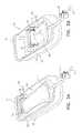
- FIGS. 3A and 3Bare schematic diagrams of an assembly base and operative elements of an assembly, according to an alternative embodiment of the present invention.
- FIG. 4is a schematic graph of pressure vs. time, according to an embodiment of the present invention.
- a temporary implantused to create a pocket
- a balloonwith a valve external to the breast, may be incorporated into the temporary implant and volumes of saline solution, each volume typically being of the order of 100 ml, may be periodically injected into the balloon.
- the time between injectionsis usually of the order of two-three weeks, and each injection typically requires a visit to a doctor's surgery.
- the relatively sudden injection of a large amount of fluidmay be uncomfortable or even somewhat painful.
- an embodiment of the present inventionprovides an enclosure, and a fluid-tight bag is located within the enclosure.
- a first end of a tubeis connected to the fluid-tight bag via a fluid-tight valve that is connected to the bag.
- a second end of the tubeis connected, typically via another fluid-tight valve, to a balloon within a breast implant fitted to an implantee.
- a spindleis located within the enclosure and is connected to the fluid-tight bag.
- the spindleis under control of the implantee, and is configured to rotate the fluid-tight bag onto the spindle, or to unroll the fluid-tight bag from the spindle.
- the rolling and unrollingtransfers fluid that is contained in the balloon, the tube, and the fluid-tight bag between these three elements.
- the implanteeSince the rolling and unrolling are under control of the implantee, the implantee is able to select the times of fluid injection to the balloon (or fluid removal from the balloon) to suit her schedule. Furthermore, it has been found that using an embodiment of the present invention is more comfortable than the periodic injections described above.
- FIG. 1is a schematic diagram illustrating use of a breast implant pressure changer assembly 10 , according to an embodiment of the present invention.
- Assembly 10comprises within the assembly a fluid-filled, fluid-tight, bag 12 , and the bag is coupled to a tube 14 that is terminated by a fluid-tight valve 16 .
- the fluid filling the bagcomprises saline solution, although in some embodiments the fluid may comprise air.
- a user 20also herein termed implantee 20 , of assembly 10 has been fitted with a temporary implant 24 after a mastectomy on a breast 22 .
- the implantcomprises a balloon, so is also herein referred to as balloon 24 .
- Balloon 24is coupled to a tube 30 which is terminated by a fluid-tight valve 32 .
- Valve 32 and at least part of tube 30are external to breast 22 , and so are typically designed to be relatively inconspicuous.
- a coupling tube 34connects between valve 16 and valve 32 .
- balloon 24 , tubes 30 , 34 , and 14 , and bag 12form a closed sealed system 40 .
- user 20is able to change the volume of bag 12 , the change of volume leading to a change of pressure in system 40 .
- the change of pressure in system 40forms a corresponding change in pressure of balloon 24 , leading in turn to a change of volume of the balloon.
- the change of volume of bag 12typically comprises the user reducing the bag volume, leading to an increase in volume of the balloon.
- user 20may desire to increase the bag 12 volume, for example to counteract an overpressure.
- Assembly 10is consequently configured to allow the user to decrease or increase the volume of bag 12 .
- assembly 10comprises a switch 44 which implantee 20 uses to change the volume of bag 12 , i.e., to increase the volume of the bag or to decrease the volume of the bag.
- implantee 20may change the volume of bag 12 using a remote system, for example by operating an application in a system controller 48 , typically a smartphone, which communicates wirelessly with assembly 10 .
- the wireless communicationtypically uses a standard protocol and technology, such as Bluetooth low energy (BLE).
- a DC motor 50is coupled to a spindle 56 around which bag 12 rolls or unrolls when the motor is operated.
- Motor 50is powered by a battery 52 , and the motor and the battery are both within assembly 10 .
- a pressure sensor 60is connected to bag 12 , so as to measure the pressure of the fluid in the bag.
- Assembly 10also comprises an assembly controller 62 which communicates with the pressure sensor and the DC motor so as to control the operation of rolling or unrolling of the bag. If, as explained above, a wireless remote system operates assembly 10 , assembly controller 62 is also configured to communicate wirelessly with controller 48 .
- FIG. 2is a schematic diagram of assembly 10 in a partly disassembled form, according to an embodiment of the present invention.
- Assembly 10comprises a cover 70 which fits over an assembly base 72 , the base holding operative elements of the assembly. Illustrated in FIG. 2 is bag 12 , which connects to tube 14 .
- DC motor 50When DC motor 50 is activated, it turns spindle 56 , via gear wheels 54 , so that the bag rolls or unrolls on the spindle. Motor 50 , gear wheels 54 , and spindle 56 are fixed within base 72 .
- the figureillustrates assembly 10 with bag 12 in an unrolled configuration. When the bag rolls onto the spindle, it withdraws tube 14 into the assembly.
- the pressure in the bagwhich is typically greater than atmospheric pressure, keeps the bag inflated and constrains the bag to move within assembly 10 so that tube 14 moves out from the assembly.
- Connecting valve 16is not illustrated in FIG. 2 .
- Mounted within assembly base 72but not visible in the figure, are battery 52 and processor 62 .
- Attached to bag 12also not visible in the figure, is pressure sensor 60 .
- FIGS. 3A and 3Bare schematic diagrams of assembly base 72 and operative elements of an assembly 80 , according to an alternative embodiment of the present invention. Apart from the differences described below, the operation of assembly 80 is generally similar to that of assembly 10 ( FIGS. 1 and 2 ), and elements indicated by the same reference numerals in both assembly 10 and assembly 80 are generally similar in construction and in operation. For simplicity, cover 70 is not shown in FIGS. 3A and 3B .
- FIG. 3Aillustrates bag 12 when it is not rolled onto spindle 56 .
- FIG. 3Billustrates bag 12 when it is partly rolled onto spindle 56 .
- assembly 10in assembly 80 the rolling or unrolling of the bag is controlled by rotation of motor 50 .
- sub-assembly 82is able to move, rolling of the bag moves the sub-assembly in a direction shown by an arrow 84 in FIG. 3B .
- assembly controller 62is typically configured to halt operation of motor 50 if the pressure measured by sensor 60 reaches or exceeds a preset safety value, such as 1010 mbar. To prevent spasmodic operation of the motor, and consequent fitful rolling or unrolling of bag 12 , controller 62 is also typically configured to provide a time delay before reactivating motor 50 once the motor has halted due the preset pressure safety value being reached.
- FIG. 4is a schematic graph of pressure vs. time, according to an embodiment of the present invention.
- the graphshows the change of pressure, as measured by sensor 60 , as implantee 20 operates assembly 10 or assembly 80 to roll bag 12 onto spindle 56 . Rolling the bag onto the spindle increases the pressure in system 40 , and particularly initially in bag 12 .
- the pressure measured by sensor 60increases until it reads the preset safety value of 1010 mbars, at which point controller 62 deactivates motor 50 , so that bag 12 does not roll onto (or roll off) spindle 56 .
- controller 62reactivates motor 50 to further roll the bag onto the spindle, so that during a time period T 3 the pressure measured by sensor 60 again increases until the pressure safety value is reached, whereupon the controller deactivates the motor.
- Implantee 20may operate assembly 10 or assembly 80 to unroll bag 12 from spindle 56 , for example to alleviate the overpressure referred to above.
- the unrolling by motor 50is typically configured to be slow enough so that the pressure remains substantially equal throughout closed system 40 .
Landscapes
- Health & Medical Sciences (AREA)
- Life Sciences & Earth Sciences (AREA)
- General Health & Medical Sciences (AREA)
- Veterinary Medicine (AREA)
- Engineering & Computer Science (AREA)
- Biomedical Technology (AREA)
- Heart & Thoracic Surgery (AREA)
- Public Health (AREA)
- Vascular Medicine (AREA)
- Animal Behavior & Ethology (AREA)
- Anesthesiology (AREA)
- Hematology (AREA)
- Cardiology (AREA)
- Oral & Maxillofacial Surgery (AREA)
- Transplantation (AREA)
- Prostheses (AREA)
- External Artificial Organs (AREA)
Abstract
Description
Claims (12)
Priority Applications (2)
| Application Number | Priority Date | Filing Date | Title |
|---|---|---|---|
| US15/432,585US10548712B2 (en) | 2016-02-29 | 2017-02-14 | Pressure changer for a breast implant |
| US16/781,170US11234808B2 (en) | 2016-02-29 | 2020-02-04 | Pressure changer for a breast implant |
Applications Claiming Priority (2)
| Application Number | Priority Date | Filing Date | Title |
|---|---|---|---|
| US201662301180P | 2016-02-29 | 2016-02-29 | |
| US15/432,585US10548712B2 (en) | 2016-02-29 | 2017-02-14 | Pressure changer for a breast implant |
Related Child Applications (1)
| Application Number | Title | Priority Date | Filing Date |
|---|---|---|---|
| US16/781,170DivisionUS11234808B2 (en) | 2016-02-29 | 2020-02-04 | Pressure changer for a breast implant |
Publications (2)
| Publication Number | Publication Date |
|---|---|
| US20170245980A1 US20170245980A1 (en) | 2017-08-31 |
| US10548712B2true US10548712B2 (en) | 2020-02-04 |
Family
ID=58212932
Family Applications (2)
| Application Number | Title | Priority Date | Filing Date |
|---|---|---|---|
| US15/432,585Expired - Fee RelatedUS10548712B2 (en) | 2016-02-29 | 2017-02-14 | Pressure changer for a breast implant |
| US16/781,170Active2037-08-17US11234808B2 (en) | 2016-02-29 | 2020-02-04 | Pressure changer for a breast implant |
Family Applications After (1)
| Application Number | Title | Priority Date | Filing Date |
|---|---|---|---|
| US16/781,170Active2037-08-17US11234808B2 (en) | 2016-02-29 | 2020-02-04 | Pressure changer for a breast implant |
Country Status (8)
| Country | Link |
|---|---|
| US (2) | US10548712B2 (en) |
| EP (1) | EP3210570A1 (en) |
| JP (1) | JP6869748B2 (en) |
| CN (1) | CN107126300A (en) |
| AU (1) | AU2017201186B2 (en) |
| CA (1) | CA2958373A1 (en) |
| IL (1) | IL250645B (en) |
| MA (1) | MA42140A (en) |
Cited By (3)
| Publication number | Priority date | Publication date | Assignee | Title |
|---|---|---|---|---|
| US11234808B2 (en)* | 2016-02-29 | 2022-02-01 | Biosense Webster (Israel) Ltd. | Pressure changer for a breast implant |
| US11491005B2 (en) | 2017-09-01 | 2022-11-08 | Mentor Worldwide Llc | Adjustable implant |
| US11678972B2 (en) | 2017-12-12 | 2023-06-20 | Mentor Worldwide Llc | Adjustable implant |
Families Citing this family (7)
| Publication number | Priority date | Publication date | Assignee | Title |
|---|---|---|---|---|
| GB2560503B (en)* | 2017-03-07 | 2019-12-11 | Gc Aesthetics Mfg Ltd | Packaging |
| GB201705707D0 (en) | 2017-04-10 | 2017-05-24 | Gc Aesthetics (Manufacturing) Ltd | Implant |
| WO2018226726A1 (en) | 2017-06-05 | 2018-12-13 | Bateman Bottle, Llc | Device for removal of implants and associated method of use |
| GB201805484D0 (en) | 2018-04-04 | 2018-05-16 | Gc Aesthetics Mfg Ltd | Implant |
| CN109717993B (en)* | 2018-12-13 | 2021-02-05 | 云南省第一人民医院 | Rehabilitation auxiliary device after mammary gland surgery |
| CN112472413B (en)* | 2019-09-11 | 2023-06-16 | 微创视神医疗科技(上海)有限公司 | Active perfusion system for ultrasonic emulsification |
| EP4132413A4 (en)* | 2020-04-07 | 2024-07-31 | Marz Medical, Inc. | METHOD AND SYSTEM FOR IN SITU TISSUE EXPANSION |
Citations (79)
| Publication number | Priority date | Publication date | Assignee | Title |
|---|---|---|---|---|
| US146805A (en) | 1874-01-27 | Improvement in breast-pads | ||
| US1091063A (en) | 1910-04-29 | 1914-03-24 | Thomas C Hutchinson | Tube-holder. |
| US1263798A (en) | 1916-12-01 | 1918-04-23 | Henry J Otto | Device for deflating tire-tubes. |
| US3852833A (en) | 1972-05-23 | 1974-12-10 | Thamert O Textil Und Kunststof | Breast prosthesis |
| US3919724A (en)* | 1974-06-07 | 1975-11-18 | Medical Eng Corp | Implantable prosthesis having a self-sealing valve |
| US3934274A (en)* | 1974-10-29 | 1976-01-27 | Hartley Jr John H | Deflatable mammary augmentation prosthesis |
| US4433440A (en) | 1979-02-26 | 1984-02-28 | Cohen I Kelman | Prosthesis formed by inner and outer inflatable containers |
| US4615704A (en) | 1984-11-26 | 1986-10-07 | Dow Corning Corporation | Shape retention tissue expander and method of using |
| US4624671A (en)* | 1984-06-25 | 1986-11-25 | Kress Donald W | Method of sizing and implanting breast prosthesis |
| US4643733A (en) | 1983-04-04 | 1987-02-17 | Hilton Becker | Permanent reconstruction implant and method of performing human tissue expansion |
| US4773908A (en) | 1986-12-18 | 1988-09-27 | Hilton Becker | Filling tube and seal construction for inflatable implant |
| US4775379A (en) | 1986-12-30 | 1988-10-04 | Mentor Corporation | Self-sealing valve for fluid fillable article |
| US4790309A (en) | 1987-04-10 | 1988-12-13 | Hilton Becker | Tissue expander stent |
| US4944749A (en) | 1985-01-23 | 1990-07-31 | Hilton Becker | Implant and inflating construction |
| US4969898A (en)* | 1988-08-08 | 1990-11-13 | Marianna Calogero | Expandable prosthesis for correcting myodystrophies |
| US4969899A (en)* | 1989-03-08 | 1990-11-13 | Cox-Uphoff International | Inflatable implant |
| US5019101A (en) | 1989-05-31 | 1991-05-28 | Purkait Bobby K | Self-sealing valve for implantable device |
| US5181907A (en) | 1990-03-20 | 1993-01-26 | Hilton Becker | Cannula and method for liposuction |
| US5219360A (en)* | 1991-05-10 | 1993-06-15 | Fortis Research Corporation | Mammary prosthesis fill and method of making same |
| WO1995004561A1 (en) | 1993-08-06 | 1995-02-16 | The Spring Consortium Limited | Apparatus for varying the quantity of contents in a receptacle |
| US5507808A (en) | 1994-10-26 | 1996-04-16 | Becker; Hilton | Filling tube and seal construction |
| US5549672A (en)* | 1991-12-26 | 1996-08-27 | Mentor Corporation | Method and apparatus for filling mammary prostheses and tissue expanders |
| US5630843A (en)* | 1994-06-30 | 1997-05-20 | Rosenberg; Paul H. | Double chamber tissue expander |
| US5723006A (en) | 1991-02-22 | 1998-03-03 | Ledergerber; Walter J. | Breast implant introducer |
| US5776159A (en)* | 1996-10-03 | 1998-07-07 | General Surgical Innovations, Inc. | Combination dissector and expander |
| US6113569A (en) | 1995-12-21 | 2000-09-05 | Very Inventive Physicians | Reciprocating liposuction device |
| DE19923183A1 (en) | 1999-05-21 | 2000-11-23 | Schlegel Ramona | Tube squeezer, especially for tubes containing medical products or foodstuffs, comprises two rollers, at least one of which is driven, which grip end of tube and squeeze it |
| US6183514B1 (en) | 1999-08-16 | 2001-02-06 | Hilton Becker | Self positioning breast prosthesis |
| US20020011497A1 (en) | 1999-02-25 | 2002-01-31 | Barry Farris | Medicinal dosing apparatus and method |
| US6540702B1 (en) | 2000-11-01 | 2003-04-01 | Maria Sarango | Breast compressing device |
| US6755861B2 (en) | 2001-10-16 | 2004-06-29 | Granit Medical Innovation, Inc. | Device for providing a portion of an organism with a desired shape |
| US20050284215A1 (en) | 2004-06-28 | 2005-12-29 | Falsetti Andrew E | Method and apparatus for preoperative estimation of breast implant volume |
| US20060100578A1 (en) | 2004-09-13 | 2006-05-11 | Tandem Medical, Inc. | Medication delivery apparatus and methods for intravenous infusions |
| US20060161196A1 (en)* | 2005-01-18 | 2006-07-20 | Widgerow Alan D | Methods of and apparatus for use in medical treatment |
| US7081136B1 (en) | 2005-04-18 | 2006-07-25 | Techno Investments Llc | Adjustable gel filled mammary prosthesis and method |
| US20070050026A1 (en)* | 2005-08-25 | 2007-03-01 | Carvallo Edward | Method and apparatus for reconstructive surgery |
| US20080275569A1 (en)* | 2004-09-16 | 2008-11-06 | Evera Medical, Inc | Tissue Augmentation Device |
| US20090210056A1 (en) | 2008-01-31 | 2009-08-20 | Milux Holding Sa | Breast implant system |
| US20100010871A1 (en) | 2004-12-31 | 2010-01-14 | Matthew Mengerink | Method and system to provide feedback data within a distributed e-commerce system |
| US20100010531A1 (en)* | 2004-09-21 | 2010-01-14 | Tadmor Shalon | Tissue Expansion Devices |
| US20100108717A1 (en) | 2007-05-07 | 2010-05-06 | Marek Szymanski | Liquid dispensing apparatus |
| US7762982B1 (en)* | 2004-12-27 | 2010-07-27 | Darshan Shah | Breast implant fill device |
| US20100204792A1 (en) | 2009-02-11 | 2010-08-12 | Greco Richard J | Permanently Adjustable Silicone Implant |
| US20100228347A1 (en)* | 2008-04-28 | 2010-09-09 | Allergan, Inc. | Flush patch for elastomeric implant shell |
| US20100324688A1 (en) | 2009-06-18 | 2010-12-23 | Mekatronix | Intervertebral spinal disc prosthesis |
| US20110106249A1 (en) | 2009-09-02 | 2011-05-05 | Hilton Becker | Self supporting and forming breast implant and method for forming and supporting an implant in a human body |
| US20110153017A1 (en)* | 2009-12-22 | 2011-06-23 | Mcclellan William T | Systems and methods for tissue expansion with fluid delivery and drainage system |
| US20110160854A1 (en)* | 2009-12-29 | 2011-06-30 | Ethicon, Inc. | Breast implants having drug-eluting reservoirs and methods therefor |
| US20110160859A1 (en) | 2008-09-12 | 2011-06-30 | Doty Keith L | Dynamic six-degrees-of-freedom intervertebral spinal disc prosthesis |
| US20110230845A1 (en) | 2006-11-17 | 2011-09-22 | B. Braun Medical Inc. | Needleless access port valves |
| US20110264213A1 (en) | 2008-12-19 | 2011-10-27 | Demiranda Jose Maria | Silicone implant with expandable compartment |
| US8080057B2 (en) | 2005-08-09 | 2011-12-20 | Steven J. Kronowitz | Methods and devices for breast reconstruction |
| US20120116509A1 (en)* | 2009-07-17 | 2012-05-10 | Milux Holding Sa | Breast implant system |
| US8197542B2 (en) | 2009-09-02 | 2012-06-12 | Hilton Becker | Self supporting implant in a human body and method for making the same without capsular contracture |
| US8202317B2 (en) | 2009-09-02 | 2012-06-19 | Hilton Becker | Self supporting and forming breast implant and method for forming and supporting an implant in a human body |
| US8308630B2 (en) | 2006-01-04 | 2012-11-13 | Allergan, Inc. | Hydraulic gastric band with collapsible reservoir |
| US20130007980A1 (en) | 2006-09-29 | 2013-01-10 | Dyson Technology Limited | Surface treating appliance |
| US20130013084A1 (en) | 2010-03-15 | 2013-01-10 | Allergan, Inc. | Bariatric device and method for weight loss |
| US20130013063A1 (en)* | 2011-07-05 | 2013-01-10 | Del Vecchio Daniel A | Cosmetic surgery sizer |
| US8394118B2 (en) | 2004-09-21 | 2013-03-12 | Airxpanders, Inc. | Tissue expanders and methods of use |
| US20130079807A1 (en) | 2011-08-22 | 2013-03-28 | Marz Medical, Inc. | Method and system for in situ tissue expansion |
| US20130237915A1 (en)* | 2011-12-02 | 2013-09-12 | Aharon Ronny Barrelli | Mobile infusion device |
| US20130245758A1 (en)* | 2010-02-05 | 2013-09-19 | Allergan, Inc. | Inflatable prostheses and methods of making same |
| US20130341353A1 (en) | 2012-06-20 | 2013-12-26 | Charles Harris | Battery operated toothpaste dispenser |
| US20140031619A1 (en) | 2012-07-27 | 2014-01-30 | Il Moon | Erection assistance device |
| US20140100656A1 (en)* | 2012-10-04 | 2014-04-10 | Innovative Biologics LLC | Restorative post-lumpectomy implant device |
| US20140156001A1 (en)* | 2012-12-05 | 2014-06-05 | Ethicon, Inc. | Valve assemblies for expandable implants and tissue expanders |
| US20140200396A1 (en) | 2008-10-31 | 2014-07-17 | Refine, Llc | Minimally invasive breast lift method with a superior tissue support and an inferior anchor |
| US20140236210A1 (en) | 2004-09-21 | 2014-08-21 | F. Mark Payne | Tissue expanders, implants, and methods of use |
| WO2016003718A1 (en) | 2014-07-03 | 2016-01-07 | Elwha Llc | Devices, methods, and systems related to expandable implants |
| US20160228603A1 (en)* | 2013-04-12 | 2016-08-11 | Miba Medical Inc. | Body augmentation device |
| US20160250017A1 (en)* | 2013-10-18 | 2016-09-01 | William T. MCCLELLAN | Tissue expander improvements |
| US20160310711A1 (en)* | 2014-01-07 | 2016-10-27 | Evan S. Luxon | Systems, devices and methods for draining and analyzing bodily fluids |
| US20170127929A1 (en) | 2000-04-14 | 2017-05-11 | Attenuex Technologies, Inc. | Implant with high vapor pressure medium |
| US20180153684A1 (en) | 2012-04-23 | 2018-06-07 | E-Vision Smart Optics, Inc. | Systems, Devices, and/or Methods for Managing Implantable Devices |
| US20180200714A1 (en)* | 2015-07-24 | 2018-07-19 | Centre National De La Recherche Scientifique | Composite woven fluidic device |
| US20180279889A1 (en)* | 2015-10-08 | 2018-10-04 | Charmcare Co., Ltd. | Wrist-worn blood pressure monitor |
| US20190091001A1 (en) | 2007-10-11 | 2019-03-28 | Peter Forsell | Method for controlling flow of intestinal contents in a patient's intestines |
| US20190111206A1 (en) | 2013-03-15 | 2019-04-18 | Peter Forsell | Operable implant |
Family Cites Families (11)
| Publication number | Priority date | Publication date | Assignee | Title |
|---|---|---|---|---|
| US4938760A (en) | 1989-03-29 | 1990-07-03 | American Medical Systems, Inc. | Female suspension procedure |
| US5882353A (en)* | 1994-04-11 | 1999-03-16 | Pmt Corporation | Mechanical tissue expander |
| US5845813A (en)* | 1997-06-20 | 1998-12-08 | Werner; Barry J. | Toothpaste dispenser |
| AU2004235622A1 (en) | 2003-12-17 | 2005-07-07 | Ethicon Endo-Surgery, Inc. | Mechanically adjustable gastric band |
| US20070276478A1 (en) | 2006-05-12 | 2007-11-29 | Micardia Corporation | Intraoperative and post-operative adjustment of an annuloplasty ring |
| WO2010042493A1 (en) | 2008-10-06 | 2010-04-15 | Allergan, Inc. | Mechanical gastric band with cushions |
| WO2010096449A2 (en)* | 2009-02-17 | 2010-08-26 | Pharmanova, Inc. | Implantable drug delivery devices |
| US8353956B2 (en) | 2009-02-17 | 2013-01-15 | Valtech Cardio, Ltd. | Actively-engageable movement-restriction mechanism for use with an annuloplasty structure |
| US10226242B2 (en) | 2013-07-31 | 2019-03-12 | Nuvasive Specialized Orthopedics, Inc. | Noninvasively adjustable suture anchors |
| US9737264B2 (en) | 2014-08-18 | 2017-08-22 | St. Jude Medical, Cardiology Division, Inc. | Sensors for prosthetic heart devices |
| US10548712B2 (en)* | 2016-02-29 | 2020-02-04 | Biosense Webster (Israel) Ltd. | Pressure changer for a breast implant |
- 2017
- 2017-02-14USUS15/432,585patent/US10548712B2/ennot_activeExpired - Fee Related
- 2017-02-16ILIL250645Apatent/IL250645B/enactiveIP Right Grant
- 2017-02-17CACA2958373Apatent/CA2958373A1/enactivePending
- 2017-02-22AUAU2017201186Apatent/AU2017201186B2/ennot_activeCeased
- 2017-02-27JPJP2017034500Apatent/JP6869748B2/ennot_activeExpired - Fee Related
- 2017-02-28CNCN201710116233.1Apatent/CN107126300A/enactivePending
- 2017-02-28EPEP17158382.6Apatent/EP3210570A1/ennot_activeWithdrawn
- 2017-02-28MAMA042140Apatent/MA42140A/enunknown
- 2020
- 2020-02-04USUS16/781,170patent/US11234808B2/enactiveActive
Patent Citations (87)
| Publication number | Priority date | Publication date | Assignee | Title |
|---|---|---|---|---|
| US146805A (en) | 1874-01-27 | Improvement in breast-pads | ||
| US1091063A (en) | 1910-04-29 | 1914-03-24 | Thomas C Hutchinson | Tube-holder. |
| US1263798A (en) | 1916-12-01 | 1918-04-23 | Henry J Otto | Device for deflating tire-tubes. |
| US3852833A (en) | 1972-05-23 | 1974-12-10 | Thamert O Textil Und Kunststof | Breast prosthesis |
| US3919724A (en)* | 1974-06-07 | 1975-11-18 | Medical Eng Corp | Implantable prosthesis having a self-sealing valve |
| US3934274A (en)* | 1974-10-29 | 1976-01-27 | Hartley Jr John H | Deflatable mammary augmentation prosthesis |
| US4433440A (en) | 1979-02-26 | 1984-02-28 | Cohen I Kelman | Prosthesis formed by inner and outer inflatable containers |
| US4643733A (en) | 1983-04-04 | 1987-02-17 | Hilton Becker | Permanent reconstruction implant and method of performing human tissue expansion |
| US4624671A (en)* | 1984-06-25 | 1986-11-25 | Kress Donald W | Method of sizing and implanting breast prosthesis |
| US4615704A (en) | 1984-11-26 | 1986-10-07 | Dow Corning Corporation | Shape retention tissue expander and method of using |
| US4944749A (en) | 1985-01-23 | 1990-07-31 | Hilton Becker | Implant and inflating construction |
| US4773908A (en) | 1986-12-18 | 1988-09-27 | Hilton Becker | Filling tube and seal construction for inflatable implant |
| US4775379A (en) | 1986-12-30 | 1988-10-04 | Mentor Corporation | Self-sealing valve for fluid fillable article |
| US4790309A (en) | 1987-04-10 | 1988-12-13 | Hilton Becker | Tissue expander stent |
| US4969898A (en)* | 1988-08-08 | 1990-11-13 | Marianna Calogero | Expandable prosthesis for correcting myodystrophies |
| US4969899A (en)* | 1989-03-08 | 1990-11-13 | Cox-Uphoff International | Inflatable implant |
| US5019101A (en) | 1989-05-31 | 1991-05-28 | Purkait Bobby K | Self-sealing valve for implantable device |
| US5181907A (en) | 1990-03-20 | 1993-01-26 | Hilton Becker | Cannula and method for liposuction |
| US5723006A (en) | 1991-02-22 | 1998-03-03 | Ledergerber; Walter J. | Breast implant introducer |
| US5219360A (en)* | 1991-05-10 | 1993-06-15 | Fortis Research Corporation | Mammary prosthesis fill and method of making same |
| US5549672A (en)* | 1991-12-26 | 1996-08-27 | Mentor Corporation | Method and apparatus for filling mammary prostheses and tissue expanders |
| WO1995004561A1 (en) | 1993-08-06 | 1995-02-16 | The Spring Consortium Limited | Apparatus for varying the quantity of contents in a receptacle |
| US5630843A (en)* | 1994-06-30 | 1997-05-20 | Rosenberg; Paul H. | Double chamber tissue expander |
| US5507808A (en) | 1994-10-26 | 1996-04-16 | Becker; Hilton | Filling tube and seal construction |
| US6113569A (en) | 1995-12-21 | 2000-09-05 | Very Inventive Physicians | Reciprocating liposuction device |
| US5776159A (en)* | 1996-10-03 | 1998-07-07 | General Surgical Innovations, Inc. | Combination dissector and expander |
| US20020011497A1 (en) | 1999-02-25 | 2002-01-31 | Barry Farris | Medicinal dosing apparatus and method |
| DE19923183A1 (en) | 1999-05-21 | 2000-11-23 | Schlegel Ramona | Tube squeezer, especially for tubes containing medical products or foodstuffs, comprises two rollers, at least one of which is driven, which grip end of tube and squeeze it |
| US6183514B1 (en) | 1999-08-16 | 2001-02-06 | Hilton Becker | Self positioning breast prosthesis |
| US20170127929A1 (en) | 2000-04-14 | 2017-05-11 | Attenuex Technologies, Inc. | Implant with high vapor pressure medium |
| US6540702B1 (en) | 2000-11-01 | 2003-04-01 | Maria Sarango | Breast compressing device |
| US6755861B2 (en) | 2001-10-16 | 2004-06-29 | Granit Medical Innovation, Inc. | Device for providing a portion of an organism with a desired shape |
| US20050284215A1 (en) | 2004-06-28 | 2005-12-29 | Falsetti Andrew E | Method and apparatus for preoperative estimation of breast implant volume |
| US20060100578A1 (en) | 2004-09-13 | 2006-05-11 | Tandem Medical, Inc. | Medication delivery apparatus and methods for intravenous infusions |
| US20080275569A1 (en)* | 2004-09-16 | 2008-11-06 | Evera Medical, Inc | Tissue Augmentation Device |
| US20140236210A1 (en) | 2004-09-21 | 2014-08-21 | F. Mark Payne | Tissue expanders, implants, and methods of use |
| US20170165025A1 (en) | 2004-09-21 | 2017-06-15 | F. Mark Payne | Tissue expanders, implants, and methods of use |
| US20100010531A1 (en)* | 2004-09-21 | 2010-01-14 | Tadmor Shalon | Tissue Expansion Devices |
| US8394118B2 (en) | 2004-09-21 | 2013-03-12 | Airxpanders, Inc. | Tissue expanders and methods of use |
| US7762982B1 (en)* | 2004-12-27 | 2010-07-27 | Darshan Shah | Breast implant fill device |
| US20100010871A1 (en) | 2004-12-31 | 2010-01-14 | Matthew Mengerink | Method and system to provide feedback data within a distributed e-commerce system |
| US20060161196A1 (en)* | 2005-01-18 | 2006-07-20 | Widgerow Alan D | Methods of and apparatus for use in medical treatment |
| US7081136B1 (en) | 2005-04-18 | 2006-07-25 | Techno Investments Llc | Adjustable gel filled mammary prosthesis and method |
| US8080057B2 (en) | 2005-08-09 | 2011-12-20 | Steven J. Kronowitz | Methods and devices for breast reconstruction |
| US7615074B2 (en) | 2005-08-25 | 2009-11-10 | Carvallo Edward | Method and apparatus for reconstructive surgery |
| US20070050026A1 (en)* | 2005-08-25 | 2007-03-01 | Carvallo Edward | Method and apparatus for reconstructive surgery |
| US8308630B2 (en) | 2006-01-04 | 2012-11-13 | Allergan, Inc. | Hydraulic gastric band with collapsible reservoir |
| US20130007980A1 (en) | 2006-09-29 | 2013-01-10 | Dyson Technology Limited | Surface treating appliance |
| US20110230845A1 (en) | 2006-11-17 | 2011-09-22 | B. Braun Medical Inc. | Needleless access port valves |
| US20100108717A1 (en) | 2007-05-07 | 2010-05-06 | Marek Szymanski | Liquid dispensing apparatus |
| US20190091001A1 (en) | 2007-10-11 | 2019-03-28 | Peter Forsell | Method for controlling flow of intestinal contents in a patient's intestines |
| US20090210056A1 (en) | 2008-01-31 | 2009-08-20 | Milux Holding Sa | Breast implant system |
| US8398710B2 (en) | 2008-01-31 | 2013-03-19 | Milux Holding Sa | Breast implant system |
| US20100228347A1 (en)* | 2008-04-28 | 2010-09-09 | Allergan, Inc. | Flush patch for elastomeric implant shell |
| US20110160859A1 (en) | 2008-09-12 | 2011-06-30 | Doty Keith L | Dynamic six-degrees-of-freedom intervertebral spinal disc prosthesis |
| US20140200396A1 (en) | 2008-10-31 | 2014-07-17 | Refine, Llc | Minimally invasive breast lift method with a superior tissue support and an inferior anchor |
| US20110264213A1 (en) | 2008-12-19 | 2011-10-27 | Demiranda Jose Maria | Silicone implant with expandable compartment |
| US20100204792A1 (en) | 2009-02-11 | 2010-08-12 | Greco Richard J | Permanently Adjustable Silicone Implant |
| US20100324688A1 (en) | 2009-06-18 | 2010-12-23 | Mekatronix | Intervertebral spinal disc prosthesis |
| US20170333179A1 (en) | 2009-07-17 | 2017-11-23 | Peter Forsell | Surgical method for the treatment of anal incontinence in women |
| US20120116509A1 (en)* | 2009-07-17 | 2012-05-10 | Milux Holding Sa | Breast implant system |
| EP2453839B1 (en) | 2009-07-17 | 2014-03-12 | Kirk Promotion LTD. | Breast implant system |
| US20110106249A1 (en) | 2009-09-02 | 2011-05-05 | Hilton Becker | Self supporting and forming breast implant and method for forming and supporting an implant in a human body |
| US8202317B2 (en) | 2009-09-02 | 2012-06-19 | Hilton Becker | Self supporting and forming breast implant and method for forming and supporting an implant in a human body |
| US8197542B2 (en) | 2009-09-02 | 2012-06-12 | Hilton Becker | Self supporting implant in a human body and method for making the same without capsular contracture |
| US20170079737A1 (en) | 2009-12-18 | 2017-03-23 | Christopher Scott Jones | Tissue expanders and methods of use |
| US20110153017A1 (en)* | 2009-12-22 | 2011-06-23 | Mcclellan William T | Systems and methods for tissue expansion with fluid delivery and drainage system |
| US20110160854A1 (en)* | 2009-12-29 | 2011-06-30 | Ethicon, Inc. | Breast implants having drug-eluting reservoirs and methods therefor |
| US20130245758A1 (en)* | 2010-02-05 | 2013-09-19 | Allergan, Inc. | Inflatable prostheses and methods of making same |
| US20130013084A1 (en) | 2010-03-15 | 2013-01-10 | Allergan, Inc. | Bariatric device and method for weight loss |
| US20130013063A1 (en)* | 2011-07-05 | 2013-01-10 | Del Vecchio Daniel A | Cosmetic surgery sizer |
| US20130079807A1 (en) | 2011-08-22 | 2013-03-28 | Marz Medical, Inc. | Method and system for in situ tissue expansion |
| US9265921B2 (en)* | 2011-08-22 | 2016-02-23 | Marz Medical, Inc. | Method and system for in situ tissue expansion |
| US20130237915A1 (en)* | 2011-12-02 | 2013-09-12 | Aharon Ronny Barrelli | Mobile infusion device |
| US20180153684A1 (en) | 2012-04-23 | 2018-06-07 | E-Vision Smart Optics, Inc. | Systems, Devices, and/or Methods for Managing Implantable Devices |
| US20130341353A1 (en) | 2012-06-20 | 2013-12-26 | Charles Harris | Battery operated toothpaste dispenser |
| US20140031619A1 (en) | 2012-07-27 | 2014-01-30 | Il Moon | Erection assistance device |
| US20140100656A1 (en)* | 2012-10-04 | 2014-04-10 | Innovative Biologics LLC | Restorative post-lumpectomy implant device |
| US20140156001A1 (en)* | 2012-12-05 | 2014-06-05 | Ethicon, Inc. | Valve assemblies for expandable implants and tissue expanders |
| US20190223971A1 (en) | 2013-02-21 | 2019-07-25 | F. Mark Payne | Tissue expanders, implants, and methods of use |
| US20190111206A1 (en) | 2013-03-15 | 2019-04-18 | Peter Forsell | Operable implant |
| US20160228603A1 (en)* | 2013-04-12 | 2016-08-11 | Miba Medical Inc. | Body augmentation device |
| US20160250017A1 (en)* | 2013-10-18 | 2016-09-01 | William T. MCCLELLAN | Tissue expander improvements |
| US20160310711A1 (en)* | 2014-01-07 | 2016-10-27 | Evan S. Luxon | Systems, devices and methods for draining and analyzing bodily fluids |
| WO2016003718A1 (en) | 2014-07-03 | 2016-01-07 | Elwha Llc | Devices, methods, and systems related to expandable implants |
| US20180200714A1 (en)* | 2015-07-24 | 2018-07-19 | Centre National De La Recherche Scientifique | Composite woven fluidic device |
| US20180279889A1 (en)* | 2015-10-08 | 2018-10-04 | Charmcare Co., Ltd. | Wrist-worn blood pressure monitor |
Non-Patent Citations (3)
| Title |
|---|
| Extended European Search Report; EP Application No. 17158382.6-1664; dated Jul. 27, 2017. |
| International Search Report and Written Opinion for International Application No. PCT/IB2018/056354, dated Nov. 16, 2018, 12 pages. |
| Mentor, "Becker Expander/Mammary Prostheses (Reconstruction Adjunct Study)," 2002, Retrieved from the internet http://www.mentorwwllc.com/documents/Becker.pdf, 16 pages. |
Cited By (3)
| Publication number | Priority date | Publication date | Assignee | Title |
|---|---|---|---|---|
| US11234808B2 (en)* | 2016-02-29 | 2022-02-01 | Biosense Webster (Israel) Ltd. | Pressure changer for a breast implant |
| US11491005B2 (en) | 2017-09-01 | 2022-11-08 | Mentor Worldwide Llc | Adjustable implant |
| US11678972B2 (en) | 2017-12-12 | 2023-06-20 | Mentor Worldwide Llc | Adjustable implant |
Also Published As
| Publication number | Publication date |
|---|---|
| CA2958373A1 (en) | 2017-08-29 |
| JP2017153957A (en) | 2017-09-07 |
| US20170245980A1 (en) | 2017-08-31 |
| US20200170784A1 (en) | 2020-06-04 |
| JP6869748B2 (en) | 2021-05-12 |
| IL250645B (en) | 2020-06-30 |
| AU2017201186B2 (en) | 2021-04-01 |
| US11234808B2 (en) | 2022-02-01 |
| AU2017201186A1 (en) | 2017-09-14 |
| MA42140A (en) | 2018-03-28 |
| EP3210570A1 (en) | 2017-08-30 |
| IL250645A0 (en) | 2017-03-30 |
| CN107126300A (en) | 2017-09-05 |
Similar Documents
| Publication | Publication Date | Title |
|---|---|---|
| US11234808B2 (en) | Pressure changer for a breast implant | |
| US11964093B2 (en) | Negative pressure device | |
| US6579301B1 (en) | Intragastric balloon device adapted to be repeatedly varied in volume without external assistance | |
| US11406483B2 (en) | Artificial sphincter system and method | |
| JP5009158B2 (en) | Tissue expansion device | |
| US9724189B2 (en) | Breast implant system | |
| US10448765B2 (en) | Inflatable pillow, method and device for inflating and deflating the same | |
| WO2018192978A1 (en) | Wound care system for reduced pressure therapy | |
| US20070066862A1 (en) | Devices and methods for providing cardiac assistance | |
| EP3100702B1 (en) | Penile prosthetic deflation assembly having a palpatable activation surface | |
| KR20190098160A (en) | Electric catheter system with improved dilation control | |
| US20180333552A1 (en) | Device for a dynamically sealing occlusion or a space-filling tamponade of a hollow organ | |
| ES2555654T3 (en) | Artificial urinary sphincter system | |
| EP2767261B1 (en) | Inflatable penile implant | |
| US20180001001A1 (en) | Novel hands-free breast pumping system | |
| CA2993184A1 (en) | Quick deployment cast | |
| US7762982B1 (en) | Breast implant fill device | |
| CN115701952A (en) | Methods and systems for in situ tissue dilation | |
| WO2020200985A1 (en) | Transurethral catheter device for bleeding control in pelvic fractures | |
| WO2016137686A1 (en) | Penile prosthetic assembly having selectively controlled vibratory unit | |
| JP2018520784A (en) | Molded elastomeric infusion pump | |
| CN222018709U (en) | Breast shield assembly, breast pump assembly and adjustment device | |
| CN109864840A (en) | Hands-free integral electric breast expander | |
| CN209490279U (en) | Convenient for the stomach tube of positioning | |
| EP3781223B1 (en) | Wound care system for negative pressure therapy |
Legal Events
| Date | Code | Title | Description |
|---|---|---|---|
| AS | Assignment | Owner name:BIOSENSE WEBSTER (ISRAEL) LTD., ISRAEL Free format text:ASSIGNMENT OF ASSIGNORS INTEREST;ASSIGNORS:GOVARI, ASSAF;EPHRATH, YARON;SIGNING DATES FROM 20160313 TO 20160315;REEL/FRAME:041254/0876 | |
| AS | Assignment | Owner name:BIOSENSE WEBSTER (ISRAEL) LTD., ISRAEL Free format text:ASSIGNMENT OF ASSIGNORS INTEREST;ASSIGNORS:GOVARI, ASSAF;EPHRATH, YARON;SIGNING DATES FROM 20170126 TO 20170307;REEL/FRAME:041573/0310 | |
| STPP | Information on status: patent application and granting procedure in general | Free format text:ADVISORY ACTION MAILED | |
| STPP | Information on status: patent application and granting procedure in general | Free format text:DOCKETED NEW CASE - READY FOR EXAMINATION | |
| STPP | Information on status: patent application and granting procedure in general | Free format text:NOTICE OF ALLOWANCE MAILED -- APPLICATION RECEIVED IN OFFICE OF PUBLICATIONS | |
| STPP | Information on status: patent application and granting procedure in general | Free format text:AWAITING TC RESP., ISSUE FEE NOT PAID | |
| STPP | Information on status: patent application and granting procedure in general | Free format text:NOTICE OF ALLOWANCE MAILED -- APPLICATION RECEIVED IN OFFICE OF PUBLICATIONS | |
| STPP | Information on status: patent application and granting procedure in general | Free format text:DOCKETED NEW CASE - READY FOR EXAMINATION | |
| STPP | Information on status: patent application and granting procedure in general | Free format text:NOTICE OF ALLOWANCE MAILED -- APPLICATION RECEIVED IN OFFICE OF PUBLICATIONS | |
| AS | Assignment | Owner name:BIOSENSE WEBSTER (ISRAEL) LTD., ISRAEL Free format text:ASSIGNMENT OF ASSIGNORS INTEREST;ASSIGNORS:GOVARI, ASSAF;EPHRATH, YARON;SIGNING DATES FROM 20191116 TO 20191120;REEL/FRAME:051099/0530 | |
| STPP | Information on status: patent application and granting procedure in general | Free format text:PUBLICATIONS -- ISSUE FEE PAYMENT VERIFIED | |
| STCF | Information on status: patent grant | Free format text:PATENTED CASE | |
| FEPP | Fee payment procedure | Free format text:MAINTENANCE FEE REMINDER MAILED (ORIGINAL EVENT CODE: REM.); ENTITY STATUS OF PATENT OWNER: LARGE ENTITY | |
| LAPS | Lapse for failure to pay maintenance fees | Free format text:PATENT EXPIRED FOR FAILURE TO PAY MAINTENANCE FEES (ORIGINAL EVENT CODE: EXP.); ENTITY STATUS OF PATENT OWNER: LARGE ENTITY | |
| STCH | Information on status: patent discontinuation | Free format text:PATENT EXPIRED DUE TO NONPAYMENT OF MAINTENANCE FEES UNDER 37 CFR 1.362 | |
| FP | Lapsed due to failure to pay maintenance fee | Effective date:20240204 |