US10548609B2 - Surgical ligation clip - Google Patents
Surgical ligation clipDownload PDFInfo
- Publication number
- US10548609B2 US10548609B2US15/668,170US201715668170AUS10548609B2US 10548609 B2US10548609 B2US 10548609B2US 201715668170 AUS201715668170 AUS 201715668170AUS 10548609 B2US10548609 B2US 10548609B2
- Authority
- US
- United States
- Prior art keywords
- leg member
- surgical clip
- tissue
- clip
- convex
- Prior art date
- Legal status (The legal status is an assumption and is not a legal conclusion. Google has not performed a legal analysis and makes no representation as to the accuracy of the status listed.)
- Active, expires
Links
Images


Classifications
- A—HUMAN NECESSITIES
- A61—MEDICAL OR VETERINARY SCIENCE; HYGIENE
- A61B—DIAGNOSIS; SURGERY; IDENTIFICATION
- A61B17/00—Surgical instruments, devices or methods
- A61B17/12—Surgical instruments, devices or methods for ligaturing or otherwise compressing tubular parts of the body, e.g. blood vessels or umbilical cord
- A61B17/122—Clamps or clips, e.g. for the umbilical cord
- A—HUMAN NECESSITIES
- A61—MEDICAL OR VETERINARY SCIENCE; HYGIENE
- A61B—DIAGNOSIS; SURGERY; IDENTIFICATION
- A61B17/00—Surgical instruments, devices or methods
- A61B17/08—Wound clamps or clips, i.e. not or only partly penetrating the tissue ; Devices for bringing together the edges of a wound
- A61B17/083—Clips, e.g. resilient
- A—HUMAN NECESSITIES
- A61—MEDICAL OR VETERINARY SCIENCE; HYGIENE
- A61B—DIAGNOSIS; SURGERY; IDENTIFICATION
- A61B17/00—Surgical instruments, devices or methods
- A61B17/0057—Implements for plugging an opening in the wall of a hollow or tubular organ, e.g. for sealing a vessel puncture or closing a cardiac septal defect
- A61B2017/00575—Implements for plugging an opening in the wall of a hollow or tubular organ, e.g. for sealing a vessel puncture or closing a cardiac septal defect for closure at remote site, e.g. closing atrial septum defects
- A61B2017/00588—Rigid or stiff implements, e.g. made of several rigid parts linked by hinges
- A—HUMAN NECESSITIES
- A61—MEDICAL OR VETERINARY SCIENCE; HYGIENE
- A61B—DIAGNOSIS; SURGERY; IDENTIFICATION
- A61B17/00—Surgical instruments, devices or methods
- A61B2017/00831—Material properties
- A61B2017/00858—Material properties high friction or non-slip
- A—HUMAN NECESSITIES
- A61—MEDICAL OR VETERINARY SCIENCE; HYGIENE
- A61B—DIAGNOSIS; SURGERY; IDENTIFICATION
- A61B17/00—Surgical instruments, devices or methods
- A61B2017/00831—Material properties
- A61B2017/00862—Material properties elastic or resilient
- A—HUMAN NECESSITIES
- A61—MEDICAL OR VETERINARY SCIENCE; HYGIENE
- A61B—DIAGNOSIS; SURGERY; IDENTIFICATION
- A61B17/00—Surgical instruments, devices or methods
- A61B17/08—Wound clamps or clips, i.e. not or only partly penetrating the tissue ; Devices for bringing together the edges of a wound
- A61B17/085—Wound clamps or clips, i.e. not or only partly penetrating the tissue ; Devices for bringing together the edges of a wound with adhesive layer
- A61B2017/086—Wound clamps or clips, i.e. not or only partly penetrating the tissue ; Devices for bringing together the edges of a wound with adhesive layer having flexible threads, filaments, laces or wires, e.g. parallel threads, extending laterally from a strip, e.g. for tying to opposing threads extending from a similar strip
Definitions
- the present disclosurerelates generally to medical devices, and more particularly, to surgical clips for ligation of tissue.
- tissuee.g., blood vessels, lymph nodes, nerves, fallopian tubes, or cardiac tissue
- ligating blood vesselse.g., veins or arteries
- Ligation of tissuemay be performed by closing the vessel with a ligation clip, or by suturing the vessel with surgical thread.
- the use of surgical thread for ligationrequires complex manipulations of the needle and suture material to form the knots required to secure the vessel. Such complex manipulations are time consuming and difficult to perform, particularly in endoscopic surgical procedures, which are characterized by limited space and visibility.
- ligation clipsare relatively easy and quick to apply. Accordingly, the use of ligation clips in endoscopic as well as open surgical procedures has grown dramatically.
- the present inventorsrecognize that there is a need to improve one more features of the ligation clips, such as initial retention of the tissue and pressure distribution.
- current ligation clipsare often subject to an undesired “watermelon-seeding” effect, when the tissue slips out of the ligation clip as it is closes. This effect may unfortunately result in tissue damage, a longer surgical procedure, and the surgeon applying excessive force to the tissue to ensure retention.
- the current ligation clipsafter being closed on the tissue, the current ligation clips often apply a non-uniform pressure distribution.
- the leg members of the current ligation clipsare typically rigid and do not conform to tissue of different sizes, causing stress localization.
- the non-uniform pressure distributionmay be especially problematic when the tissue is not properly positioned in the clip, for example, over-compression may occur when the tissue is positioned adjacent to either of a hinge portion or the latching mechanism.
- This non-uniform pressure distributionmay result in tissue damage and/or rupture, especially when applied to overstressed., fibrotic, and/or infarcted tissue.
- the current ligation clipsdo not sufficiently ligate bundles of tissue, for example, due to varying sizes of the tissue in the bundle.
- the disclosed methods and systemsare directed to mitigating or overcoming one or more of the problems set forth above and/or other problems in the prior art.
- a surgical clip configured to ligate a tissuemay include a first leg member and a second leg member.
- the first leg membermay have a proximal portion, a distal portion, a convex first inner surface, and a convex first outer surface.
- the first leg membermay also include an inner portion at least partially defining the first inner surface and an outer portion at least partially defining the first outer surface.
- the inner and outer portionsmay be joined at first and second portions of the first leg member and separated by a first channel.
- the second leg membermay include a proximal portion, a distal portion, a second inner surface, and a second outer surface.
- the first and second leg membersmay be movable relative to each other between an open configuration and a closed configuration, and the first and second inner surfaces may be configured to ligate the tissue when in the closed configuration.
- the first inner portionmay be configured to be resiliently deflected in the closed configuration;
- the second inner surfacemay include a convex inner surface, and the first and second inner surfaces may be configured to pinch a proximal portion as the surgical clip is initially compressed;
- the first inner portion and the first outer portionmay be integral to the first leg member;
- the first inner portionmay have a width that may be substantially equal to a width of the first outer portion;
- the first channelmay extend in a longitudinal direction for at least half of a length of the first leg member;
- the first channelmay extend in the longitudinal direction for greater than three-quarters of the length of the first leg member;
- a hinge portionmay join the proximal end portions of the first and second leg members;
- the hinge portionmay be integral to the first and second leg members;
- the surgical clipmay further include: at least one first tooth positioned on the first inner surface; and at least one second tooth positioned on the second inner surface;
- the first and second leg membersmay include latching elements configured to secure the
- a methodmay include ligating a tissue with a surgical clip having a first leg member and a second leg member.
- the first leg membermay include an inner portion, an outer portion, and a channel between the inner portion and the outer portion.
- the methodmay include moving the first leg member relative to the second leg member from an open configuration toward a closed configuration.
- the methodmay also include compressing at least a portion of the tissue between the first leg member and the second leg member by engaging the tissue with a convex inner surface of the inner portion.
- the methodmay further include deflecting the inner portion into the channel as the tissue is compressed.
- resiliently deflecting the inner portionmay include resiliently deflecting the inner portion toward a concave surface of an outer portion of the first leg member; the method may further include retracting the tissue with the surgical clip after compressing the at least a portion of the tissue; and moving the surgical clip into the closed configuration after retracting the tissue with the surgical clip; the method may further include securing the surgical clip in the closed configuration with latching elements on the first and second leg members.
- a surgical clip configured to ligate a tissuemay include a first leg member and a second leg member, and the first leg member may have an inner portion having a convex inner surface, an outer portion, and a channel between the inner portion and the outer portion.
- the first leg membermay be configured to move relative to the second leg member from an open configuration toward a closed configuration, the first leg member and the second leg member may be configured to compress at least a portion of the tissue by engaging the tissue with the convex inner surface, and the inner portion may be configured to resiliently deflect into the channel as the tissue is compressed.
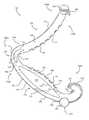
- FIG. 1illustrates a side elevation view of a first exemplary embodiment of a surgical ligation clip of the present disclosure.
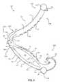
- FIG. 2illustrates a perspective view of the first embodiment of the surgical ligation clip of FIG. 1 .
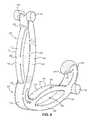
- FIG. 3illustrates another perspective view of the first exemplary embodiment of the surgical ligation clip of FIGS. 1 and 2 .
- FIGS. 4A-Dillustrate a series of configurations of the first exemplary embodiment of the surgical ligation clip of FIGS. 1-3 , when applied to close or ligate tissue.
- FIGS. 5A-Billustrate additional configurations of the first exemplary embodiment of the surgical ligation clip of FIGS. 1-3 , when applied to close or ligate tissue.
- FIG. 6illustrates a side view of a second exemplary embodiment of a surgical ligation clip of the present disclosure.
- FIG. 7illustrates a first perspective view of the second exemplary embodiment of the surgical ligation clip of FIG. 6 .
- FIG. 8illustrates a second perspective view of the second exemplary embodiment of the surgical ligation clip of FIGS. 6 and 7 .
- proximal end portionrefers to the specified end portion of a device or its component which is generally closer to the medical personnel handling or manipulating the device as it is intended to be used
- distal end portionshall refer to the specified end portion of a device or its component which is opposite the proximal end portion.
- the present inventionis generally directed to a surgical ligation clip configured to ligate tissue (e.g., a blood vessel).
- the clipmay comprise first and second leg members configured to provide increased initial retention and pressure distribution.
- the first leg membermay comprise an inner portion (e.g, an inner rib) having a convex portion that enables pinching of a proximal portion of the tissue against a convex surface of the second leg member as the clip is initially compressed.
- the pinching of the tissuemay grasp the tissue to enable manipulation of the tissue as the clip is partially open.
- the convex surfacesmay further include teeth that grasp and pull the tissue toward a proximal end portion of the clip, as the tissue is further compressed.
- the inner portionmay be resiliently compressed toward a concave inner surface of an outer portion (e.g., an outer rib) of the first leg member providing favorable pressure distribution on the tissue as it is ligated.
- the flexibility of the inner portionmay enable favorable pressure distribution on tissue of different shapes, sizes, and/or stiffnesses, and tissue compressed at different positions along the length of the clip. This may reduce leakage, tissue damage and/or rupture during the ligation, for example, of overstressed, fibrotic, and/or infarcted tissue,
- the flexibility of the inner portionmay enhance ligation of a bundle of tissues, such as a plurality of lymph nodes.
- the flexibility of the inner portionmay conform to the various tissues in the bundle, while ensuring sufficient pressure is applied to ligate each of the tissues in the bundle.
- FIG. 1is a side elevation view of a first embodiment of a surgical ligation clip 100 .
- FIGS. 2 and 3show perspective views of clip 100 .
- Clip 100is particularly useful as hemostatic clips that can be latched around a vessel to thereby stop or reduce the flow of fluid through the vessel.
- Clip 100may have a proximal end portion 100 A and a distal end portion 100 B.
- Clip 100may further include a first leg member 102 having a proximal end portion 102 A and distal end portion 102 B, and a second leg member 104 having a proximal end portion 104 A and distal end portion 104 B.
- First and second leg members 102 , 104may include surfaces having curved portions.
- first leg member 102may include a first inner surface 108 and a first outer surface 110
- second leg member 104may include a second inner surface 112 and a second outer surface 114 .
- first inner surface 108may include a convex portion
- first outer surface 110may include a convex portion.
- Second inner surface 112may include a convex portion, and second outer surface 114 may include a concave portion.
- First inner surface 108 and second inner surface 112may be configured to pinch a proximal portion of the tissue as clip 100 is initially applied, and first inner surface 108 may be resiliently flexible along its length to distribute pressure over a width of the tissue as the tissue is ligated.
- First and second leg members 102 , 104may be joined at proximal end portions 102 A, 104 A by a hinge portion 106 .
- Hinge portion 106may be resilient and/or integral to clip 100 .
- Hinge portion 106may have a continuous concave inner surface 116 and a continuous convex outer surface 118 .
- Concave inner surface 116 of hinge portion 106may join first inner surface 108 of first leg member 102 and second inner surface 112 of second leg member 104 .
- Convex outer surface 118 of hinge portion 106may join first outer surface 110 of first leg member 102 and second outer surface 114 of second leg member 104 .
- Hinge portion 106may also include a curved slot 120 located between curved hinge surfaces 116 , 118 , and may be positioned closer to concave inner surface 116 than to convex outer surface 118 .
- Curved slot 120may extend completely through hinge portion 106 from side to side and its opposite ends 122 , 124 may extend into proximal end portions 102 A, 102 B of first and second leg members 102 , 104 , respectively.
- Curved slot 120may provide added flexibility and resiliency to hinge portion 106 , but concave inner surface 116 may prevent any portion of a clamped vessel from being trapped within curved slot 120 .
- Clip 100may also include a latching mechanism formed by latching elements on first and second leg members 102 , 104 .
- first leg member 102may transition to a curved, C-shaped hook section 126 at its distal end.
- Second leg member 104may transition to a pointed tip section 128 at its distal end.
- the distal portion of hook section 126may curve inwardly and point generally toward concave inner surface 116 of hinge portion 106 .
- Hook section 126may have one or more transverse beveled surfaces 130 and a concave inner surface which merges with first inner surface 108 to define a latching member or recess 132 .
- Latching recess 132may conform and engage with tip section 128 in the course of compressing clip 100 into a latched or secured position around a vessel or other tissue.
- Leg members 102 , 104may include one or more bosses along their length to engage a clip applier.
- first leg member 102may include cylindrical bosses 146 , 148 (depicted in FIGS. 2-3 ) protruding perpendicular to each of opposed side surfaces 138 , 140 adjacent to distal end portion 102 B of first leg member 102 and immediately inward of hook section 126 .
- a bridge section 150may couple bosses 146 , 148 together, and bosses 146 , 148 may project outwardly beyond first outer surface 110 of first leg member 102 .
- Second leg member 104may also include cylindrical bosses 152 , 154 at distal end portion 104 B, protruding perpendicular to each of opposed side surfaces 142 , 144 of second leg member 104 and extending longitudinally forward beyond the point of tip section 128 .
- clip 100may be designed to be compressed into a latched or locked position around the vessel through the use of an appropriate clip applier, such as a type described in U.S. Pat. No. 5,100,416, the entire disclosure of which is incorporated herein.
- the clip appliermay engage and pivot bosses 146 , 148 , 152 , 154 of clip 100 inwardly about hinge portion 106 .
- First leg member 102may include an inner portion 162 and an outer portion 164 joined at a first portion 166 and a second portion 168 of first leg member 102 .
- Inner portion 162may include a convex portion When viewed from the inner side of first leg member 102 , having an inner surface 170 that may be convex and an outer surface 172 that may be concave.
- Outer portion 164may include a concave portion when viewed from the inner side of first leg member 102 , having an inner surface 174 that may be concave and an outer surface 176 that may be convex. It is contemplated that inner portion 162 and/or outer portion 164 may have a number of different curvatures.
- inner portion 162may include one or more concave, convex, and/or flat inner surfaces and one or more concave, convex, and/or flat outer surfaces.
- Outer portion 164may include one or more c concave, convex, and/or flat inner surfaces and one or more concave, convex, and/or flat outer surfaces.
- Inner surface 170 of inner portion 162may define at least a portion of first inner surface 108
- outer surface 176 of outer portion 164may define at least a portion of first outer surface 110 of clip 100 .
- inner portion 162 and outer portion 164may extend greater than half of a length of first leg member 102 (e.g., defining greater than half of surfaces 108 , 110 ).
- inner portion 162 and outer portion 164may extend greater than three-quarters of the length of first leg member 102 (e.g., defining greater than three-quarters of surfaces 108 , 110 ).
- Each of inner portion 162 and outer portion 164may have a thickness less than a thickness of second leg member 104 .
- each of inner portion 162 and/or outer portion 164may be substantially half of the thickness of each of first leg member 102 and second leg member 104 .
- the reduced thickness of inner portion 162may provide the desired flexibility to conform to tissue compressed by clip 100 .
- Inner portion 162 , outer portion 164 , and second leg member 104may have substantially the same width in the transverse direction.
- Inner portion 162 and outer portion 164may be separated by at least one aperture or channel 178 extending longitudinally along the clip 100 to enable compression of first leg member 102 .
- the channel 178may extend between side surfaces 138 , 140 of first leg member 102 .
- channel 178may enable inner portion 162 to resiliently compress toward outer portion 164 and distribute load along the length of the tissue, while more effectively gripping and retaining the tissue within clip 100 .
- the channel 178may extend in a longitudinal direction more than half a length of first leg member 102 .
- the channel 178may extend in a longitudinal direction greater than three-quarters of the length of first leg member 102 , as depicted in FIG. 1 .
- outer portion 164may provide additional room for resilient deflection of inner portion 162 , allowing clip 100 to ligate and properly distribute pressure to tissue of varying shapes, sizes, and/or stiffnesses.
- inner portion 162may provide continuous ligating pressure to tissue in a latched configuration, even as the tissue necrotizes and shrinks.
- one or more ribsmay extend between inner portion 162 and outer portion 164 to provide stiffness to first leg member 102 when desired.
- clip 100may include a first plurality of teeth 134 protruding on first inner surface 108 , and a second plurality of teeth 136 protruding on second inner surface 112 .
- Teeth 134 , 136may maximize security of compressed tissue and minimize migration.
- Teeth 134 , 136may extend the width of first and second leg members 102 , 104 , and may be angled towards proximal end portion 102 A of clip 100 .
- teeth 134 , 136may aid in initial pinching and pulling of the tissue toward proximal end portion 100 A, and retention or gripping of the tissue when further compressed or ligated.
- Teeth 134 , 136may also enable clip 100 to manipulate tissue when clip 100 is at least partially open.
- teeth 134 , 136may be omitted.
- one or more of teeth 134 , 136may be in an “out-board” configuration (e.g., extending from one or more of the side surfaces 136 - 142 ), as disclosed in U.S. Provisional Patent Application No. 62/523,562, the entire disclosure of which is incorporated. herein.
- FIGS. 4A-Dillustrate a series of configurations of clip 100 of FIG. 1 being applied to a tissue 500 (e.g., a blood vessel).
- tissue 500e.g., a blood vessel.
- One or more of the configurations shown in FIGS. 4A-Dmay provide one or more steps of a method of compressing and/or manipulating tissue 500 (e.g., temporarily or permanently ligating a blood vessel).
- tissue 500may be positioned between first and second leg members 102 , 104 when clip 100 is in an open configuration.
- clip 100may be initially compressed to pinch a proximal portion of tissue 500 between inner surfaces 108 , 112 proximate to hinge portion 106 , preventing tissue 500 from sliding out of distal end portion 100 B as clip 100 closes (e.g., a “watermelon-seeding” effect).
- the initial pinching of tissue 500may also allow a surgeon to manipulate tissue 500 with clip 100 While being at least partially open, as exemplary depicted in FIG. 4B .
- tissue 500is proximate to other bodily structures
- the surgeonmay pinch (or compress) and retract tissue 500 away from the other structures to prevent the other structures from interfering with the ligation and/or to prevent the latching mechanism from damaging the other structures.
- the initial pinching of tissue 500may further aid in skeletonizing tissue 500 prior to closure.
- tissue 500may be further compressed by first and second leg members 102 , 104 .
- inner surfaces 108 , 112 and teeth 134 , 136may further pinch and pull tissue 500 toward hinge portion 106 .
- the pinching and pulling of tissue 500may enhance security of tissue 500 and further reduce the potential of the “watermelon-seeding” effect.
- second leg member 104may pull tissue 500 in the proximal direction by sliding along inner surface 170 toward hinge portion 106 , or vice versa.
- the proximal sliding of second leg member 104may be provided by the interaction of the convexity of each of first inner surface 108 and second inner surface 112 .
- second inner surface 112may contact (either directly or through tissue) a proximal portion of inner surface 170 of inner portion 162 , which causes second leg member 104 and/or tissue 500 to slide proximally toward hinge portion 106 .
- the proximal sliding of second leg member 104may, additionally or alternatively, be provided by abutment of tip section 128 of first leg member 102 with hook section 126 of second leg member 104 .
- the abutment of tip section 128 onto a proximal angled surface of hook section 126may cause first leg member 102 to elongate relative to second leg member 104 , and second leg member 104 to pull tissue 500 toward hinge portion 106 .
- the compression of clip 100may progressively ligate tissue 500 from proximal end portion 100 A to distal end portion 100 B of clip 100 .
- the compression of clip 100may further resiliently deflect inner portion 162 toward outer portion 164 distributing the pressure along the width of tissue 500 .
- inner portion 162may conform to the size of tissue 500 , apply spring-like resilient pressure along the entire width of tissue 500 , and/or reduce any potential stress localizations.
- Outer portion 164may also elongate as clip 100 is compressed.
- clip 100may secure tissue 500 in a ligated configuration, for example, through the latching mechanism.
- Inner portion 162may provide continuous ligating pressure to tissue 500 in the latched configuration, even as tissue 500 necrotizes and shrinks.
- clip 100may be configured to provide a favorable pressure distribution to different types and sizes of tissue, even when the tissue is not centered in clip 100 .
- clip 100may ensure proper pressure distribution to substantially rigid tissue 510 (as depicted in FIG. 5A ) or substantially compliant tissue 520 (as depicted in FIG. 5B ).
- tissue 510may be overstressed, fibrotic, and/or infarcted tissue that may he subject to stress localization when compressed because of the inability to conform to compressive loads.
- Clip 100may reduce any resulting stress localization of tissue 500 through deflection of inner portion 162 .
- Inner portion 162may resiliently deflect into channel 178 , conform to tissue 510 , 520 , and prevent any over compression. When applied to compliant tissue 520 , inner portion 162 may deflect a reduced extent. Furthermore, the flexibility of the inner portion may enhance ligation of a bundle of tissues, such as a plurality of lymph nodes. The flexibility of the inner portion may conform to the various tissues in the bundle, while ensuring sufficient pressure is applied to ligate each of the tissues in the bundle.
- Inner portion 162may also deflect along any portion of its length. For example if tissue 510 , 520 is positioned proximate to hinge portion 106 , a proximal portion of inner portion 162 may deflect to accommodate tissue 510 , 520 . On the other hand, if tissue 510 , 520 is positioned proximate to the latching mechanism, a distal portion of inner portion 162 may deflect to accommodate tissue 510 , 520 . In that sense, clip 100 may reduce stress localization due to proximity of tissue 510 , 520 to either of the latching mechanism or hinge portion 106 .
- Clip 100may further be applied to tissue bundles (e.g., tissue, vessels, glands, lymph nodes, and nerves) having irregular shapes.
- tissue bundlese.g., tissue, vessels, glands, lymph nodes, and nerves
- inner portion 162may conform individually to each of the blood vessels of the DVC to ensure that adequate ligation pressure is applied to each blood vessel, tissue structure or lymph node.
- FIG. 6is a side view of a second embodiment of a surgical ligation clip 200 .
- FIGS. 7 and 8show perspective views of clip 200 .
- Clip 200may have a proximal end portion 200 A and a distal end portion 200 B.
- Clip 200may further include a first leg member 202 having a proximal end portion 202 A and distal end portion 202 B, and a second leg member 204 having a proximal end portion 204 A and distal end portion 204 B.
- First and second leg members 202 , 204may include surfaces having curved portions.
- first leg member 202may include a first inner surface 208 and a first outer surface 210
- second leg member 204may include a second inner surface 212 and a second outer surface 214 . As illustrated in FIGS.
- first inner surface 208may include a convex portion
- second outer surface 210may include a convex portion
- the second inner surface 212may include a convex portion
- the second outer surface 214may include a convex portion.
- First and second leg members 202 , 204may be joined at proximal end portions 202 A, 204 A by a hinge portion 206 .
- Hinge portion 206may be resilient and/or integral to clip 200 .
- Clip 200may also include a latching mechanism formed by latching elements on first and second leg members 202 , 204 .
- first leg member 202may transition to a curved, C-shaped hook section 226 at its distal end.
- Leg members 202 , 204may also include one or more bosses along their length to engage a clip applier.
- clip 200may include a first plurality of teeth (not shown) protruding on first inner surface 208 , and a second plurality of teeth (not shown) protruding on second inner surface 212 , for example, as depicted in FIGS. 1-3 .
- Second leg member 202may include an inner portion 262 and an outer portion 264 joined at a first portion 266 and a second portion 268 of first leg member 202 .
- Inner portion 262may include a convex portion when viewed from inner side of first leg member 202 , having an inner surface 270 that may be convex and an outer surface 272 that may be concave.
- Outer portion 264may include a. concave portion when viewed from inner side of first leg member 202 , having an inner surface 274 that may be concave and an outer surface 276 that may be convex. It is contemplated that inner portion 262 and/or outer portion 264 may have a number of different curvatures.
- inner portion 262may include one or more concave, convex, and/or flat inner surfaces and one or more concave, convex, and/or flat outer surfaces.
- Outer portion 264may include one or more concave, convex, and/or flat inner surfaces and one or more concave, convex, and/or flat outer surfaces.
- Inner surface 270 of inner portion 262may define at least a portion of first inner surface 208
- outer surface 276 of outer portion 264may define at least a portion of first outer surface 210 of clip 200 .
- inner portion 262 and outer portion 264may extend greater than half of a length of first leg member 202 (e.g., defining greater than half of surfaces 208 , 210 ).
- inner portion 262 and outer portion 264may extend greater than three-quarters of a longitudinal length first leg member 202 (e.g., defining greater than three-quarters of the length of surfaces 208 , 210 ).
- Each of inner portion 262 and outer portion 264may have a thickness less than a thickness of second leg member 204 .
- the thickness of each of inner portion 262 and/or outer portion 264may be substantially half of the thickness of each of first leg member 202 and second leg member 204 .
- the reduced thickness of inner portion 262may provide the desired flexibility to conform to tissue compressed by clip 200 .
- Inner portion 262 , outer portion 164 , and second leg member 204may have substantially the same width in the transverse direction.
- Inner portion 262 and outer portion 264may be separated by at least one aperture or channel 278 extending longitudinally along the clip 200 to enable compression of first leg member 202 .
- the channel 278may extend between side surfaces 238 , 240 of first leg member 202 .
- channel 278may enable inner portion 262 to resiliently compress toward outer portion 264 and distribute load along the length of the tissue, while more effectively gripping and retaining the tissue within clip 200 .
- the channel 278may extend in a longitudinal direction more than half a length of the first leg member 202 .
- the channel 278may extend in a longitudinal direction greater than three-quarters of the length of the first leg member 202 , as depicted in FIG.
- the concavity of outer portion 264may provide additional room for resilient deflection of inner portion 262 , allowing clip 200 to ligate and properly distribute pressure to tissue of varying shapes, sizes, and/or stiffnesses.
- inner portion 262may provide continuous ligating pressure to tissue in a latched configuration, even as the tissue necrotizes and shrinks.
- one or more ribsmay extend between inner portion 262 and outer portion 264 to provide stiffness to first leg member 202 when desired.
- Second leg member 204may include an inner portion 280 and an outer portion 282 joined at a first portion 284 and a second portion 286 of first leg member 204 .
- Inner portion 280may include a convex portion When viewed from the inner side of second leg member 204 , having an inner surface 288 that may be convex and an outer surface 290 that may be concave.
- Outer portion 282may include a concave portion when viewed from the inner side of first leg member 204 , having an inner surface 292 that may be concave and an outer surface 294 that may be convex. It is contemplated that inner portion 280 and/or outer portion 282 may have a number of different curvatures.
- inner portion 280may include one or more concave, convex, and/or flat inner surfaces and one or more concave, convex, and/or flat outer surfaces.
- Outer portion 282may include one or more concave, convex, and/or flat inner surfaces and one or more concave, convex, and/or flat outer surfaces.
- Convex inner surface 288 of inner portion 280may define at least a portion of second inner surface 212
- convex outer surface 294 of outer portion 282may define at least a portion of second outer surface 214 of clip 200 .
- inner portion 280 and outer portion 282may extend greater than half of a length of second leg member 204 (e.g., defining greater than half of surfaces 212 , 214 ).
- inner portion 280 and outer portion 282may extend greater than three-quarters of the length of second leg member 204 (e.g, defining greater than three-quarters of the length of surfaces 212 . 214 ).
- Each of inner portion 280 and outer portion 282may have a reduced thickness to provide desired flexibility to conform to tissue compressed by clip 200 .
- Inner portion 280may have a greater width in the transverse direction than the outer portion 282 .
- Inner portion 280 and outer portion 282may further define at least one aperture or channel 296 extending between side surfaces 242 , 244 of second leg member 204 to enable compression of second leg member 204 .
- channel 296may enable inner portion 280 to resiliently compress toward outer portion 282 and distribute load along the length of the tissue, while more effectively gripping and retaining the tissue within clip 200 .
- the channel 296may extend in a longitudinal direction more than half a length of second leg member 202 .
- the channel 296may extend in a longitudinal direction greater than three-quarters of the length of second leg member 204 , as depicted in FIG. 6 .
- outer portion 282may provide additional room for resilient deflection of inner portion 280 , allowing clip 200 to ligate and properly distribute pressure to tissue of varying shapes, sizes, and/or stiffnesses.
- inner portion 280may provide continuous ligating pressure to tissue in a latched configuration, even as the tissue necrotizes and shrinks.
- one or more ribsmay extend between inner portion 280 and outer portion 282 to provide stiffness to second leg member 204 when desired.
- the term “longitudinal”is directed to the dimension which extends along the length of surgical clip 100 , 200 and/or leg members 102 , 104 , 202 , 204 from respective proximal end portions to respective distal end portions, as would be commonly understood by one of skill in the art.
- the “transverse” directionis directed to any axis or direction which is orthogonal to the longitudinal lengths of surgical clip 100 , 200 or leg members 102 , 104 , 202 , 204 , which would be normal to the plane of view, for example, in FIG. 1 .
- Clip 100 , 200may be made of any suitable size and may be applied to any number of tissues, such as blood vessels, lymph nodes, nerves, fallopian tubes, or cardiac tissue.
- Clip 100 , 200may be constructed from any suitable biocompatible material, such as certain metals and polymers. However, the present invention is particularly suitable for practice with polymeric clips.
- clip 100 , 200preferably comprises a one-piece integral polymeric body formed from a suitable strong biocompatible engineering plastic such as the type commonly used for surgical implants.
- Exemplary materialsinclude homopolymer or co-polymer polyacetal, polyethylene terephthalate (PET), polybutylene terephthalate (PBT), polyoxymethylene, or other thermoplastic materials having similar properties that can be injection-molded, extruded or otherwise processed into like articles.
- PETpolyethylene terephthalate
- PBTpolybutylene terephthalate
- polyoxymethylenepolyoxymethylene
- Parts List surgical ligation clip100 proximal end portion 100A distal end portion 100B first leg member 102 proximal end portion 102A distal end portion 102B second leg member 104 proximal end portion 104A distal end portion 104B hinge portion 106 first inner surface 108 first outer surface 110 second inner surface 112 second outer surface 114 inner surface 116 outer surface 118 curved slot 120 opposite end 122 opposite end 124 hook section 126 tip section 128 transverse beveled surfaces 130 recess 132 first plurality of teeth 134 second plurality of teeth 136 side surfaces 138 side surfaces 140 side surfaces 142 side surfaces 144 boss 146 boss 148 bridge section 150 boss 152 boss 154 inner portion 162 deflect inner portion 162 outer portion 164 first portion 166 second portion 168 inner surface 170 outer surface 172 inner surface 174 outer surface 176 aperture 178 channel 178 surgical ligation clip 200 proximal end portion 200A distal end portion 200B first leg member 202 proximal end portion 202A distal end portion
Landscapes
- Health & Medical Sciences (AREA)
- Life Sciences & Earth Sciences (AREA)
- Surgery (AREA)
- Molecular Biology (AREA)
- Engineering & Computer Science (AREA)
- Biomedical Technology (AREA)
- Heart & Thoracic Surgery (AREA)
- Medical Informatics (AREA)
- Nuclear Medicine, Radiotherapy & Molecular Imaging (AREA)
- Animal Behavior & Ethology (AREA)
- General Health & Medical Sciences (AREA)
- Public Health (AREA)
- Veterinary Medicine (AREA)
- Reproductive Health (AREA)
- Vascular Medicine (AREA)
- Surgical Instruments (AREA)
Abstract
Description
| Parts List |
| surgical ligation clip | 100 | ||
| proximal end portion | 100A | ||
| distal end portion | 100B | ||
| first leg member | 102 | ||
| proximal end portion | 102A | ||
| distal end portion | 102B | ||
| second leg member | 104 | ||
| proximal end portion | 104A | ||
| distal end portion | 104B | ||
| hinge portion | 106 | ||
| first inner surface | 108 | ||
| first outer surface | 110 | ||
| second inner surface | 112 | ||
| second outer surface | 114 | ||
| inner surface | 116 | ||
| outer surface | 118 | ||
| curved slot | 120 | ||
| opposite end | 122 | ||
| opposite end | 124 | ||
| hook section | 126 | ||
| tip section | 128 | ||
| transverse beveled surfaces | 130 | ||
| recess | 132 | ||
| first plurality of teeth | 134 | ||
| second plurality of teeth | 136 | ||
| side surfaces | 138 | ||
| side surfaces | 140 | ||
| side surfaces | 142 | ||
| side surfaces | 144 | ||
| boss | 146 | ||
| boss | 148 | ||
| bridge section | 150 | ||
| boss | 152 | ||
| boss | 154 | ||
| inner portion | 162 | ||
| deflect inner portion | 162 | ||
| outer portion | 164 | ||
| first portion | 166 | ||
| second portion | 168 | ||
| inner surface | 170 | ||
| outer surface | 172 | ||
| inner surface | 174 | ||
| outer surface | 176 | ||
| aperture | 178 | ||
| channel | 178 | ||
| surgical ligation clip | 200 | ||
| proximal end portion | 200A | ||
| distal end portion | 200B | ||
| first leg member | 202 | ||
| proximal end portion | 202A | ||
| distal end portion | 202B | ||
| second leg member | 204 | ||
| proximal end portion | 204A | ||
| distal end portion | 204B | ||
| hinge portion | 206 | ||
| first inner surface | 208 | ||
| first outer surface | 210 | ||
| second inner surface | 212 | ||
| second outer surface | 214 | ||
| inner surface | 216 | ||
| outer surface | 218 | ||
| curved slot | 220 | ||
| opposite end | 222 | ||
| opposite end | 224 | ||
| C-shaped hook section | 226 | ||
| tip section | 228 | ||
| transverse beveled surfaces | 230 | ||
| recess | 232 | ||
| side surface | 238 | ||
| side surface | 240 | ||
| side surface | 242 | ||
| side surface | 244 | ||
| boss | 246 | ||
| boss | 248 | ||
| bridge section | 250 | ||
| boss | 252 | ||
| boss | 254 | ||
| inner portion | 262 | ||
| outer portion | 264 | ||
| first portion | 266 | ||
| second portion | 268 | ||
| inner surface | 270 | ||
| outer surface | 272 | ||
| inner surface | 274 | ||
| outer surface | 276 | ||
| aperture | 278 | ||
| inner portion | 280 | ||
| outer portion | 282 | ||
| first portion | 284 | ||
| second portion | 286 | ||
| inner surface | 288 | ||
| outer surface | 290 | ||
| inner surface | 292 | ||
| outer surface | 294 | ||
| aperture | 296 | ||
| tissue | 500 | ||
| rigid tissue | 510 | ||
| compliant tissue | 520 | ||
Claims (29)
Priority Applications (3)
| Application Number | Priority Date | Filing Date | Title |
|---|---|---|---|
| US15/668,170US10548609B2 (en) | 2016-08-03 | 2017-08-03 | Surgical ligation clip |
| US16/780,832US11576680B2 (en) | 2016-08-03 | 2020-02-03 | Surgical ligation clip |
| US18/109,019US20230190300A1 (en) | 2016-08-03 | 2023-02-13 | Surgical ligation clip |
Applications Claiming Priority (2)
| Application Number | Priority Date | Filing Date | Title |
|---|---|---|---|
| US201662370502P | 2016-08-03 | 2016-08-03 | |
| US15/668,170US10548609B2 (en) | 2016-08-03 | 2017-08-03 | Surgical ligation clip |
Related Child Applications (1)
| Application Number | Title | Priority Date | Filing Date |
|---|---|---|---|
| US16/780,832ContinuationUS11576680B2 (en) | 2016-08-03 | 2020-02-03 | Surgical ligation clip |
Publications (2)
| Publication Number | Publication Date |
|---|---|
| US20180036008A1 US20180036008A1 (en) | 2018-02-08 |
| US10548609B2true US10548609B2 (en) | 2020-02-04 |
Family
ID=61071888
Family Applications (3)
| Application Number | Title | Priority Date | Filing Date |
|---|---|---|---|
| US15/668,170Active2038-03-29US10548609B2 (en) | 2016-08-03 | 2017-08-03 | Surgical ligation clip |
| US16/780,832Active2038-09-04US11576680B2 (en) | 2016-08-03 | 2020-02-03 | Surgical ligation clip |
| US18/109,019PendingUS20230190300A1 (en) | 2016-08-03 | 2023-02-13 | Surgical ligation clip |
Family Applications After (2)
| Application Number | Title | Priority Date | Filing Date |
|---|---|---|---|
| US16/780,832Active2038-09-04US11576680B2 (en) | 2016-08-03 | 2020-02-03 | Surgical ligation clip |
| US18/109,019PendingUS20230190300A1 (en) | 2016-08-03 | 2023-02-13 | Surgical ligation clip |
Country Status (7)
| Country | Link |
|---|---|
| US (3) | US10548609B2 (en) |
| EP (1) | EP3493747A4 (en) |
| JP (1) | JP6837127B2 (en) |
| CN (1) | CN109788947B (en) |
| AU (1) | AU2017305440B2 (en) |
| CA (1) | CA3032824C (en) |
| WO (1) | WO2018027032A1 (en) |
Cited By (12)
| Publication number | Priority date | Publication date | Assignee | Title |
|---|---|---|---|---|
| US20210068732A1 (en)* | 2019-09-10 | 2021-03-11 | Becton, Dickinson And Company | Blood collection devices, systems, and methods |
| US20210236133A1 (en)* | 2020-01-31 | 2021-08-05 | Covidien Lp | Ligation Clip With Controlled Tissue Compression |
| US11266408B2 (en) | 2017-03-21 | 2022-03-08 | Teleflex Medical Incorporated | Clip applier having stabilizing member |
| US11534177B2 (en) | 2017-03-21 | 2022-12-27 | Teleflex Medical Incorporated | Flexible stabilizing member for a clip applier |
| US11648014B2 (en)* | 2017-11-14 | 2023-05-16 | Teleflex Medical Incorporated | Surgical clip |
| USD993411S1 (en)* | 2017-11-03 | 2023-07-25 | Covidien Lp | Ligation clip with controlled tissue compression |
| US11911043B2 (en) | 2017-06-22 | 2024-02-27 | Teleflex Medical Incorporated | Surgical clip |
| US11992222B2 (en) | 2019-12-19 | 2024-05-28 | Teleflex Medical Incorporated | Surgical clip |
| US12023041B2 (en) | 2017-03-21 | 2024-07-02 | Teleflex Medical Incorporated | Clip applier |
| US12102334B2 (en) | 2017-03-21 | 2024-10-01 | Teleflex Medical Incorporated | Clip applier with stabilizing member |
| US12279774B2 (en) | 2018-09-26 | 2025-04-22 | Teleflex Medical Incorporated | Clip applier with stabilizing member |
| US12318094B2 (en) | 2019-09-26 | 2025-06-03 | Teleflex Medical Incorporated | Clip applier |
Families Citing this family (26)
| Publication number | Priority date | Publication date | Assignee | Title |
|---|---|---|---|---|
| US10548609B2 (en) | 2016-08-03 | 2020-02-04 | Teleflex Medical Incorporated | Surgical ligation clip |
| CN110740694B (en) | 2017-03-21 | 2023-03-28 | 泰利福医疗公司 | Clip applier with replaceable tip |
| WO2018175610A1 (en)* | 2017-03-21 | 2018-09-27 | Teleflex Medical Incorporated | Surgical clip and clip applier |
| USD838847S1 (en)* | 2017-10-20 | 2019-01-22 | Dahong Zhang | Hemostatic clamp |
| US10932788B2 (en) | 2018-04-11 | 2021-03-02 | Covidien Lp | Ligation clip with latching and retention features |
| US10932789B2 (en) | 2018-04-11 | 2021-03-02 | Covidien Lp | Ligation clip with latching and retention features |
| US11033279B2 (en) | 2018-04-24 | 2021-06-15 | Covidien Lp | Ligation clip with retention features |
| EP3796847B1 (en)* | 2018-05-22 | 2025-02-19 | Boston Scientific Scimed, Inc. | Tissue engagement device |
| US12220119B2 (en) | 2018-05-22 | 2025-02-11 | Boston Scientific Scimed, Inc. | Tissue engagement device |
| US11304703B2 (en) | 2018-05-25 | 2022-04-19 | Covidien Lp | Ligation clip removal device |
| KR102092347B1 (en)* | 2018-07-16 | 2020-03-23 | 주식회사 엔도비전 | Banana clip for removing hemorrhoids and Surgical tool set including the same |
| US11317923B2 (en) | 2018-08-13 | 2022-05-03 | Covidien Lp | Ligation clip with improved hinge |
| US11304704B2 (en) | 2018-08-22 | 2022-04-19 | Covidien Lp | Surgical clip applier and ligation clips |
| KR102852635B1 (en)* | 2018-11-16 | 2025-08-29 | 텔리플렉스 메디컬 인코포레이티드 | Surgical clip |
| US11471165B2 (en) | 2019-05-08 | 2022-10-18 | Covidien Lp | Ligation clip cartridge |
| US11707282B2 (en) | 2019-07-02 | 2023-07-25 | Covidien Lp | Multi-piece ligation clip |
| USD907204S1 (en) | 2019-08-02 | 2021-01-05 | Covidien Lp | Ligation clip |
| USD907203S1 (en) | 2019-08-02 | 2021-01-05 | Covidien Lp | Ligation clip |
| US11395660B2 (en) | 2019-08-05 | 2022-07-26 | Covidien Lp | Stackable ligation clip |
| USD907200S1 (en) | 2019-08-05 | 2021-01-05 | Covidien Lp | Ligation clip |
| EP4129211A4 (en)* | 2020-03-24 | 2024-04-24 | Jichi Medical University | MEDICAL INSTRUMENT FOR LIGATURE OR SIMILAR |
| US12114866B2 (en) | 2020-03-26 | 2024-10-15 | Covidien Lp | Interoperative clip loading device |
| WO2022010464A1 (en)* | 2020-07-08 | 2022-01-13 | A2 Medical Systems LLC | Ligation clips with anti-migration features |
| EP4308015A4 (en)* | 2021-03-16 | 2025-01-08 | Covidien LP | Ligation clip including flexible insert assembly |
| AU2022325511A1 (en)* | 2021-08-10 | 2024-02-29 | Sure Retractors Ltd | Retractors |
| CN114010253B (en)* | 2021-11-02 | 2023-07-07 | 苏州美东汇成精密部件有限公司 | Adjustable ligature clip |
Citations (145)
| Publication number | Priority date | Publication date | Assignee | Title |
|---|---|---|---|---|
| US1728322A (en) | 1928-02-22 | 1929-09-17 | Badrian Max | Device for elastically clamping off the male urethra |
| US3503397A (en) | 1967-09-21 | 1970-03-31 | American Hospital Supply Corp | Atraumatic surgical clamp |
| US3766925A (en) | 1971-05-25 | 1973-10-23 | Eljay Hospital Prod Corp | Surgical clamp with cam-action lever |
| US3825012A (en) | 1973-04-13 | 1974-07-23 | H Nicoll | Reusable umbilical cord clamp for veterinary use |
| US3867944A (en) | 1972-10-27 | 1975-02-25 | Wood Ernest C | Hemostatic clip and applicator therefor |
| US3874042A (en) | 1973-01-22 | 1975-04-01 | Biospectrum Inc | Clamp for thin walled tubing |
| GB2069848A (en) | 1980-02-25 | 1981-09-03 | Ethicon Inc | Double-latched plastic ligating clips |
| US4337774A (en) | 1978-06-14 | 1982-07-06 | Metatech Corporation | Micro surgical clip |
| US4345600A (en) | 1980-08-04 | 1982-08-24 | Senco Products, Inc. | Purse-stringer |
| US4346869A (en) | 1981-03-12 | 1982-08-31 | Macneill Robert L | Tube clamp |
| US4390019A (en) | 1979-02-28 | 1983-06-28 | Leveen Harry H | Blood vessel clamp |
| EP0086640A2 (en) | 1982-02-12 | 1983-08-24 | Ethicon, Inc. | Non-metallic, bio-compatible hemostatic clips |
| US4418694A (en) | 1979-06-18 | 1983-12-06 | Ethicon, Inc. | Non-metallic, bio-compatible hemostatic clips |
| US4450840A (en) | 1982-02-26 | 1984-05-29 | Ethicon, Inc. | Ligating clip with flanged base having a recessed engaging face |
| US4458682A (en) | 1982-08-02 | 1984-07-10 | Ethicon, Inc. | Non-metallic, bio-compatible hemostatic clips (ring lock clips) |
| US4487205A (en) | 1982-04-26 | 1984-12-11 | Ethicon, Inc. | Non-metallic, bio-compatible hemostatic clips |
| US4519392A (en) | 1982-10-12 | 1985-05-28 | Lingua Robert W | Hemostasing muscle clips for needleless surgery |
| US4527562A (en) | 1979-06-18 | 1985-07-09 | Ethicon, Inc. | Non-metallic, bio-compatible hemostatic clips |
| US4550729A (en) | 1981-08-27 | 1985-11-05 | Ethicon, Inc. | Non-metallic, bio-compatible hemostatic clips with interlocking latch means |
| US4579118A (en) | 1983-06-01 | 1986-04-01 | Ethicon, Inc. | Hemostatic clip with penetration means |
| US4588160A (en) | 1985-03-27 | 1986-05-13 | Sherwood Medical Company | Tube clamping device |
| US4589626A (en) | 1985-03-13 | 1986-05-20 | Bioresearch Inc. | Hose clamp |
| JPS61259652A (en) | 1985-05-10 | 1986-11-17 | エチコン・インコ−ポレ−テツド | Bonding clip and clip adapting instrument |
| US4638804A (en) | 1980-02-25 | 1987-01-27 | Ethicon, Inc. | Double-latched non-metallic, bio-compatible hemostatic clip |
| US4712549A (en) | 1985-07-01 | 1987-12-15 | Edward Weck & Co. | Automatic hemostatic clip applier |
| US4716886A (en) | 1986-05-01 | 1988-01-05 | Norman Schulman | Umbilical cord clamp and cutters |
| US4726372A (en) | 1986-09-19 | 1988-02-23 | Metatech Corporation | Hemostatic clip |
| US4807622A (en) | 1985-09-20 | 1989-02-28 | Kato Hatsujo Kaisha, Ltd. | Tube cutting and separating implement for conduit of blood or the like |
| US4822348A (en) | 1987-05-13 | 1989-04-18 | Donn Casey | Surgical clips |
| EP0314064A2 (en) | 1987-10-26 | 1989-05-03 | Pilling Weck Incorporated | Plastic ligating clips |
| US4870965A (en) | 1988-03-04 | 1989-10-03 | Jahanger Mohammed S | Umbilical cord cutting and clamping device |
| US4936447A (en) | 1989-09-26 | 1990-06-26 | Horizon Surgical Inc. | Hemostatic clip holder |
| US4938765A (en) | 1989-06-22 | 1990-07-03 | Life Centers, Inc. | Surgical silicon loops |
| US4942886A (en) | 1989-02-22 | 1990-07-24 | Timmons John W | External incontinency device |
| US4950275A (en) | 1989-07-19 | 1990-08-21 | Cyanamid Italia S.P.A. | Bowel-anastomosis-ring holder pincers |
| US4961499A (en) | 1990-01-04 | 1990-10-09 | Pilling Co. | Hemostatic clip cartridge |
| US4972949A (en) | 1989-09-26 | 1990-11-27 | Horizon Surgical, Inc. | Hemostatic clip holder for small clips |
| US4976722A (en) | 1989-05-22 | 1990-12-11 | Ethicon, Inc. | Surgical hemostatic clips |
| US5002552A (en) | 1987-11-10 | 1991-03-26 | Donn Casey | Surgical clip |
| US5009657A (en) | 1989-12-14 | 1991-04-23 | Mohammed S. Jahanger | Umbilical cord cutting and clamping device |
| US5026382A (en) | 1990-08-27 | 1991-06-25 | Horizon Surgical, Inc. | Hemostatic clip |
| JPH03178648A (en) | 1989-10-17 | 1991-08-02 | Edward Weck Inc | Penetration type plastic clip for clipper |
| US5047038A (en) | 1985-07-01 | 1991-09-10 | Edward Weck Incorporated | Automatic hemostatic clip applier |
| US5046611A (en) | 1990-10-22 | 1991-09-10 | Edward Weck Incorporated | Hemostatic clip cartridge |
| US5078731A (en) | 1990-06-05 | 1992-01-07 | Hayhurst John O | Suture clip |
| US5100416A (en) | 1989-10-17 | 1992-03-31 | Edward Weck Incorporated | Ligating clip applying instrument |
| US5104395A (en) | 1989-07-03 | 1992-04-14 | Edward Weck Incorporated | Automatic hemostatic clip applicator |
| US5112343A (en) | 1991-04-05 | 1992-05-12 | Edward Weck Incorporated | Endoscopic clip appliers |
| US5127915A (en) | 1984-10-29 | 1992-07-07 | Mattson Philip D | Surgical instrument for severing and clamping an umbilical cord |
| US5160339A (en) | 1991-06-18 | 1992-11-03 | Ethicon, Inc. | Endoscopic suture clip |
| US5171251A (en) | 1992-03-02 | 1992-12-15 | Ethicon, Inc. | Surgical clip having hole therein and method of anchoring suture |
| US5171252A (en) | 1991-02-05 | 1992-12-15 | Friedland Thomas W | Surgical fastening clip formed of a shape memory alloy, a method of making such a clip and a method of using such a clip |
| US5201416A (en) | 1990-10-22 | 1993-04-13 | Edward Weck Incorporated | Hemostatic clip cartridge |
| US5234449A (en) | 1992-07-16 | 1993-08-10 | Ethicon, Inc. | Suture clip with reduced hinge mass |
| US5259405A (en) | 1992-01-29 | 1993-11-09 | Hua Chou Kuo | Structure of a barette |
| US5279416A (en) | 1992-06-05 | 1994-01-18 | Edward Weck Incorporated | Ligating device cartridge with separable retainer |
| US5330442A (en) | 1992-10-09 | 1994-07-19 | United States Surgical Corporation | Suture retaining clip |
| US5330487A (en) | 1992-12-17 | 1994-07-19 | Tfi Acquistion Corp. | Drive mechanism for surgical instruments |
| US5366458A (en) | 1990-12-13 | 1994-11-22 | United States Surgical Corporation | Latchless surgical clip |
| US5462555A (en) | 1993-12-30 | 1995-10-31 | United States Surgical Corporation | Umbilical cord clip and applicator |
| US5487746A (en) | 1994-11-23 | 1996-01-30 | Yu; George W. | Surgical clip having a longitudinal opening through which clamped tissue protrudes |
| US5501693A (en) | 1994-07-06 | 1996-03-26 | United States Surgical Corporation | Surgical hemostatic clip |
| US5509920A (en) | 1993-04-16 | 1996-04-23 | United States Surgical Corporation | Surgical hemostatic clip |
| US5549621A (en) | 1993-05-14 | 1996-08-27 | Byron C. Sutherland | Apparatus and method for performing vertical banded gastroplasty |
| US5575802A (en) | 1994-01-15 | 1996-11-19 | Femcare (Cyprus) Limited | Medical clip |
| US5667516A (en) | 1995-05-01 | 1997-09-16 | Allen; Sean A. | Mechanism for cutting an umbilical cord |
| US5697938A (en) | 1993-09-30 | 1997-12-16 | Price Invena Aps | Device for squeezing and cutting an umbilical cord |
| US5713911A (en) | 1996-10-03 | 1998-02-03 | United States Surgical Corporation | Surgical clip |
| US5713912A (en) | 1995-08-30 | 1998-02-03 | Stress Management, Inc. | Ligating clip having ramp-shaped vessel clamping members and tool for applying same |
| US5722982A (en) | 1996-09-26 | 1998-03-03 | University Technology Corporation | Strabismus surgery apparatus and method |
| US5725542A (en) | 1995-03-09 | 1998-03-10 | Yoon; Inbae | Multifunctional spring clips and cartridges and applicators therefor |
| US5810853A (en) | 1996-01-16 | 1998-09-22 | Yoon; Inbae | Knotting element for use in suturing anatomical tissue and methods therefor |
| US5846255A (en) | 1996-01-31 | 1998-12-08 | Casey Medical Products Limited | Surgical clip |
| US5908430A (en) | 1995-06-07 | 1999-06-01 | Appleby; Timothy | Easy loading hemostatic clip and cartridge |
| US5921991A (en) | 1997-10-23 | 1999-07-13 | Biomax Technologies Inc. | Multi-colored umbilical cord clamp |
| US5925052A (en) | 1996-06-26 | 1999-07-20 | Simmons; Paul L. | Umbilical surgical scissors |
| US5997548A (en) | 1998-07-22 | 1999-12-07 | Jahanger; Mohammed S. | Umbilical cord cutting and clamping device |
| US6015417A (en) | 1996-01-25 | 2000-01-18 | Reynolds, Jr.; Walker | Surgical fastener |
| US6131576A (en) | 1998-03-23 | 2000-10-17 | Davis; Paul K. | Male incontinence clamp, kit and method of use |
| GB2353710A (en) | 1999-08-06 | 2001-03-07 | Henleys Medical Supplies Ltd | Umbilical cord clamp |
| US6210419B1 (en) | 1998-12-18 | 2001-04-03 | Aesculap Ag & Co. Kg | Surgical clip |
| US6217590B1 (en) | 1999-01-22 | 2001-04-17 | Scion International, Inc. | Surgical instrument for applying multiple staples and cutting blood vessels and organic structures and method therefor |
| US6261303B1 (en) | 1998-12-18 | 2001-07-17 | Aesculap Ag & Co. Kg | Surgical clip |
| US6349727B1 (en) | 2000-05-25 | 2002-02-26 | Pos-T-Vac, Inc. | Penile clamp for inhibiting incontinence |
| US6391035B1 (en) | 2000-03-24 | 2002-05-21 | Timothy Appleby | Hemostatic clip removal instrument |
| US20020068946A1 (en) | 2000-12-06 | 2002-06-06 | Kortenbach Juergen A. | Apparatus for the endoluminal treatment of gastroesophageal reflux disease (GERD) |
| US6419682B1 (en) | 2000-03-24 | 2002-07-16 | Timothy Appleby | Hemostatic clip cartridge |
| US20020111640A1 (en) | 2001-02-13 | 2002-08-15 | Krause William R. | Urological device for the incontinent male |
| US20020169459A1 (en) | 1999-11-14 | 2002-11-14 | Michael Porat | Device for clamping and cutting a flexible deformable tube |
| JP2002345828A (en) | 2001-05-23 | 2002-12-03 | Asahi Optical Co Ltd | Endoscope clip device |
| US6537289B1 (en) | 1999-11-29 | 2003-03-25 | General Surgical Innovations, Inc. | Blood vessel clip applicator |
| US20030074009A1 (en) | 2001-10-16 | 2003-04-17 | Cetus, Lc | Umbilical cord cutting and clamping device |
| US6699258B1 (en) | 1999-11-17 | 2004-03-02 | Femcare (Cyprus) Limited | Sterilization and ligation clips |
| US20040059359A1 (en) | 2002-09-20 | 2004-03-25 | Wilson Donald F. | Ligating clip with integral penetrating hook |
| US6719766B1 (en) | 2000-08-24 | 2004-04-13 | Novare Surgical Systems, Inc. | Surgical clamp pads having surface overlay |
| US20040172043A1 (en) | 2001-06-05 | 2004-09-02 | Watson Richard L. | Umbilical cord clamp and cutter |
| US6824547B2 (en) | 2001-07-13 | 2004-11-30 | Pilling Weck Incorporated | Endoscopic clip applier and method |
| US6843253B2 (en) | 2002-12-11 | 2005-01-18 | C&L Medical Supply Corporation | Urinary-control device |
| US6880699B2 (en) | 2002-08-27 | 2005-04-19 | Pilling Weck Incorporated | Cartridge for holding asymmetric surgical clips |
| US20050149069A1 (en) | 2001-12-04 | 2005-07-07 | Bertolero Arthur A. | Left atrial appendage devices and methods |
| US20050165423A1 (en) | 2004-01-23 | 2005-07-28 | Pilling Weck Incorporated | Ligating clip with integral tissue-securing mechanism |
| US20050165421A1 (en) | 2004-01-22 | 2005-07-28 | Pilling Weck Incorporated | Ligating clip with integral interlocking latch mechanism |
| US20050165429A1 (en) | 2004-01-23 | 2005-07-28 | Peter Douglas | Surgical clamp possessing a combined parallel and scissor style clamp head |
| US20050165422A1 (en) | 2004-01-22 | 2005-07-28 | Pilling Weck Incorporated | Ligating clip with integral cutting guide |
| US6989017B2 (en) | 1998-07-27 | 2006-01-24 | Thomas J. Fogarty | Surgical clamp pad with interdigitating teeth |
| US7001412B2 (en) | 2004-01-28 | 2006-02-21 | Pilling Weck Incorporated | Surgical clip with integral suture-securing mechanism |
| US7052504B2 (en) | 2002-11-19 | 2006-05-30 | Teleflex Incorporated | Automated-feed surgical clip applier and related methods |
| US20060217749A1 (en) | 2005-03-24 | 2006-09-28 | Pilling Weck Incorporated | Reduced closure force ligating clip |
| WO2006102578A1 (en) | 2005-03-24 | 2006-09-28 | Pilling Weck Incorporated | Reduced closure force ligating clip |
| US7131977B2 (en) | 2002-08-27 | 2006-11-07 | Pilling Weck Incorporated | Apparatus and method for removing a clip |
| US20070083218A1 (en) | 2005-10-12 | 2007-04-12 | A Morris Steven | Coated ligating clip |
| US7211091B2 (en) | 2002-08-27 | 2007-05-01 | Pilling Weck Incorporated | Fingertip-actuated surgical clip applier and related methods |
| US7211092B2 (en) | 2002-11-19 | 2007-05-01 | Pilling Weck Incorporated | Automated-feed surgical clip applier and related methods |
| US20070118161A1 (en) | 2005-11-22 | 2007-05-24 | Kennedy Daniel L | Non-snag polymer ligating clip |
| US20070149989A1 (en) | 2005-12-22 | 2007-06-28 | Santilli Albert N | Vascular and Intestinal Occlusion |
| US20070276417A1 (en) | 2004-07-02 | 2007-11-29 | Mendes Jr Jose B | Laterally Curved Surgical Clip |
| US7329266B2 (en) | 2001-07-31 | 2008-02-12 | Research Surgical Pty Ltd | Surgical clamps |
| US20080287976A1 (en) | 2007-05-14 | 2008-11-20 | Weaner Lauren S | Gastric band with engagement member |
| US20080312670A1 (en) | 2006-01-11 | 2008-12-18 | Aesculap Ag | Surgical ligature clip |
| US20090012545A1 (en) | 2005-07-14 | 2009-01-08 | Idx Medical, Ltd. | Apparatus and Methods for Occluding a Hallow Anatomical Structure |
| US20090171380A1 (en) | 2007-12-31 | 2009-07-02 | Whiting Paul E | Ligation clip with flexible clamping feature |
| US7585304B2 (en) | 2004-02-02 | 2009-09-08 | Teleflex Medical Incorporated | Endoscopic clip applying apparatus with improved aperture for clip release and related method |
| US20090240266A1 (en) | 2008-03-21 | 2009-09-24 | Dennis William G | Vessel Occlusion Clip and Application Thereof |
| CN101543418A (en) | 2009-04-30 | 2009-09-30 | 何定甫 | Single-side umbilical clamp |
| US7635374B2 (en) | 2006-03-09 | 2009-12-22 | Niti Surgical Solutions Ltd. | Endoscopic full thickness resection using surgical compression clips |
| US7645285B2 (en) | 2004-05-26 | 2010-01-12 | Idx Medical, Ltd | Apparatus and methods for occluding a hollow anatomical structure |
| US20100114131A1 (en) | 2008-11-05 | 2010-05-06 | Adam Rotunda | Skin tag removal system |
| GB2465560A (en) | 2008-11-19 | 2010-05-26 | Frank Vinzenz Benedikt | Absorbable veterinary sterilisation clamp |
| US20100211080A1 (en) | 2009-02-13 | 2010-08-19 | Dean Trivisani | Umbiliguard |
| US20100274268A1 (en) | 2009-04-24 | 2010-10-28 | Singh Errol O | Squeeze-to-set medical clamp |
| US20110022079A1 (en) | 2009-01-08 | 2011-01-27 | Coherex Medical, Inc. | Medical device for modification of left atrial appendage and related systems and methods |
| US7963964B2 (en) | 2000-02-10 | 2011-06-21 | Santilli Albert N | Surgical clamp assembly with electrodes |
| US7992757B2 (en) | 2006-05-03 | 2011-08-09 | Raptor Ridge Llc | Systems and methods of tissue closure |
| US20110245848A1 (en) | 2002-08-08 | 2011-10-06 | Interrad Medical, Inc. | Non-invasive surgical ligation clip system and method of using |
| US20110295291A1 (en) | 2010-05-28 | 2011-12-01 | Dean Trivisani | Novel Vascular Clamp |
| US20120083803A1 (en) | 2010-10-02 | 2012-04-05 | Patel Manoj B | Asymmetrical surgical clip with penetrating lock, non-slip clamping surface, severable hinge, hinge boss and pivoting applicator tip |
| WO2012075532A1 (en) | 2010-12-07 | 2012-06-14 | Globetek 2000 Pty Ltd | Surgical clip and clip manipulation device therefor |
| US8262639B2 (en) | 2002-01-31 | 2012-09-11 | Fenwal, Inc. | Irreversible flow control clamp |
| US20130006271A1 (en) | 2011-03-29 | 2013-01-03 | Ocunetics, Inc. | Fasteners, Deployment Systems, and Methods for Ophthalmic Tissue Closure and Fixation of Ophthalmic Prostheses and Other Uses |
| US20130261642A1 (en) | 2011-09-15 | 2013-10-03 | Teleflex Medical Incorporated | Manual surgical ligation clip applier |
| US20140243862A1 (en) | 2011-10-20 | 2014-08-28 | Atsina Surgical, Llc | Ligation clip |
| US9084596B2 (en) | 2012-02-27 | 2015-07-21 | Cook Medical Technologies Llc | Suture clamp and gastrointestinal suture anchor set device using same |
| CN105054989A (en) | 2015-07-03 | 2015-11-18 | 桐庐洲济医疗器械有限公司 | Disposable vascular clamp |
| US9220507B1 (en) | 2012-10-14 | 2015-12-29 | Manoj B. Patel | Tissue spreading vascular clips with locking mechanism and non-slip clamping surfaces |
| US20160174981A1 (en)* | 2014-12-12 | 2016-06-23 | Atricure, Inc. | Occlusion clip |
Family Cites Families (13)
| Publication number | Priority date | Publication date | Assignee | Title |
|---|---|---|---|---|
| CA1157335A (en) | 1979-06-18 | 1983-11-22 | Namassivaya Doddi | Plastic ligating clips |
| JP3178648B2 (en) | 1995-12-28 | 2001-06-25 | 住友金属工業株式会社 | Protective film coating equipment for semiconductor substrates |
| US8118826B2 (en) | 2007-09-27 | 2012-02-21 | Swan Valley Medical, Incorporated | Method of performing a suprapubic transurethral cystostomy and associated procedures and apparatus therefor |
| CN101507646B (en)* | 2009-03-26 | 2012-08-22 | 杭州康基医疗器械有限公司 | Vascular clamp die |
| CN102028517A (en) | 2011-01-21 | 2011-04-27 | 常州市三联星海医疗器械制造有限公司 | Tissue clamp |
| CA2830073A1 (en) | 2011-03-21 | 2012-09-27 | The Administrators Of The Tulane Educational Fund | Multi-component detachable jaw tools and methods of using and making same |
| US20130226200A1 (en)* | 2012-02-28 | 2013-08-29 | Boston Scientific Scimed, Inc. | Clip applier |
| US9282972B1 (en)* | 2012-10-14 | 2016-03-15 | Innovative Urololy, Llc | Surgical clips with penetrating locking mechanism and non-slip clamping surfaces |
| CN103919589A (en)* | 2014-03-10 | 2014-07-16 | 浙江微度医疗器械有限公司 | Anti-shedding hemostatic clamp |
| WO2017017587A2 (en)* | 2015-07-24 | 2017-02-02 | Cliptip Medical Ltd | Thickness-adjustable hemostatic clips, clip appliers, and applications thereof |
| US10548609B2 (en) | 2016-08-03 | 2020-02-04 | Teleflex Medical Incorporated | Surgical ligation clip |
| CN106264646A (en)* | 2016-08-29 | 2017-01-04 | 张大宏 | Strongly run-resistant hemostatic clamp |
| CA3068282C (en) | 2017-06-22 | 2022-06-28 | Teleflex Medical Incorporated | Surgical clip |
- 2017
- 2017-08-03USUS15/668,170patent/US10548609B2/enactiveActive
- 2017-08-03CACA3032824Apatent/CA3032824C/enactiveActive
- 2017-08-03JPJP2019506083Apatent/JP6837127B2/enactiveActive
- 2017-08-03CNCN201780060067.6Apatent/CN109788947B/enactiveActive
- 2017-08-03EPEP17837683.6Apatent/EP3493747A4/enactivePending
- 2017-08-03WOPCT/US2017/045298patent/WO2018027032A1/ennot_activeCeased
- 2017-08-03AUAU2017305440Apatent/AU2017305440B2/enactiveActive
- 2020
- 2020-02-03USUS16/780,832patent/US11576680B2/enactiveActive
- 2023
- 2023-02-13USUS18/109,019patent/US20230190300A1/enactivePending
Patent Citations (164)
| Publication number | Priority date | Publication date | Assignee | Title |
|---|---|---|---|---|
| US1728322A (en) | 1928-02-22 | 1929-09-17 | Badrian Max | Device for elastically clamping off the male urethra |
| US3503397A (en) | 1967-09-21 | 1970-03-31 | American Hospital Supply Corp | Atraumatic surgical clamp |
| US3766925A (en) | 1971-05-25 | 1973-10-23 | Eljay Hospital Prod Corp | Surgical clamp with cam-action lever |
| US3867944A (en) | 1972-10-27 | 1975-02-25 | Wood Ernest C | Hemostatic clip and applicator therefor |
| US3874042A (en) | 1973-01-22 | 1975-04-01 | Biospectrum Inc | Clamp for thin walled tubing |
| US3825012A (en) | 1973-04-13 | 1974-07-23 | H Nicoll | Reusable umbilical cord clamp for veterinary use |
| US4337774A (en) | 1978-06-14 | 1982-07-06 | Metatech Corporation | Micro surgical clip |
| US4390019A (en) | 1979-02-28 | 1983-06-28 | Leveen Harry H | Blood vessel clamp |
| US4527562A (en) | 1979-06-18 | 1985-07-09 | Ethicon, Inc. | Non-metallic, bio-compatible hemostatic clips |
| US4418694A (en) | 1979-06-18 | 1983-12-06 | Ethicon, Inc. | Non-metallic, bio-compatible hemostatic clips |
| JPS56151034A (en) | 1980-02-25 | 1981-11-21 | Ethicon Inc | Plastic double latch clamp clip |
| US4638804A (en) | 1980-02-25 | 1987-01-27 | Ethicon, Inc. | Double-latched non-metallic, bio-compatible hemostatic clip |
| GB2069848A (en) | 1980-02-25 | 1981-09-03 | Ethicon Inc | Double-latched plastic ligating clips |
| US4345600A (en) | 1980-08-04 | 1982-08-24 | Senco Products, Inc. | Purse-stringer |
| US4346869A (en) | 1981-03-12 | 1982-08-31 | Macneill Robert L | Tube clamp |
| US4550729A (en) | 1981-08-27 | 1985-11-05 | Ethicon, Inc. | Non-metallic, bio-compatible hemostatic clips with interlocking latch means |
| EP0086640A2 (en) | 1982-02-12 | 1983-08-24 | Ethicon, Inc. | Non-metallic, bio-compatible hemostatic clips |
| US4476865A (en) | 1982-02-12 | 1984-10-16 | Ethicon, Inc. | Non-metallic, bio-compatible hemostatic clips |
| US4450840A (en) | 1982-02-26 | 1984-05-29 | Ethicon, Inc. | Ligating clip with flanged base having a recessed engaging face |
| US4487205A (en) | 1982-04-26 | 1984-12-11 | Ethicon, Inc. | Non-metallic, bio-compatible hemostatic clips |
| US4458682A (en) | 1982-08-02 | 1984-07-10 | Ethicon, Inc. | Non-metallic, bio-compatible hemostatic clips (ring lock clips) |
| US4519392A (en) | 1982-10-12 | 1985-05-28 | Lingua Robert W | Hemostasing muscle clips for needleless surgery |
| US4579118A (en) | 1983-06-01 | 1986-04-01 | Ethicon, Inc. | Hemostatic clip with penetration means |
| US5127915A (en) | 1984-10-29 | 1992-07-07 | Mattson Philip D | Surgical instrument for severing and clamping an umbilical cord |
| US4589626A (en) | 1985-03-13 | 1986-05-20 | Bioresearch Inc. | Hose clamp |
| US4588160A (en) | 1985-03-27 | 1986-05-13 | Sherwood Medical Company | Tube clamping device |
| EP0201344B1 (en) | 1985-05-10 | 1989-12-27 | Ethicon, Inc. | Ligating clip and clip applier |
| JPS61259652A (en) | 1985-05-10 | 1986-11-17 | エチコン・インコ−ポレ−テツド | Bonding clip and clip adapting instrument |
| US4712549A (en) | 1985-07-01 | 1987-12-15 | Edward Weck & Co. | Automatic hemostatic clip applier |
| US5047038A (en) | 1985-07-01 | 1991-09-10 | Edward Weck Incorporated | Automatic hemostatic clip applier |
| US4807622A (en) | 1985-09-20 | 1989-02-28 | Kato Hatsujo Kaisha, Ltd. | Tube cutting and separating implement for conduit of blood or the like |
| US4716886A (en) | 1986-05-01 | 1988-01-05 | Norman Schulman | Umbilical cord clamp and cutters |
| US4726372A (en) | 1986-09-19 | 1988-02-23 | Metatech Corporation | Hemostatic clip |
| US4822348A (en) | 1987-05-13 | 1989-04-18 | Donn Casey | Surgical clips |
| US4834096A (en) | 1987-10-26 | 1989-05-30 | Edward Weck Incorporated | Plastic ligating clips |
| EP0314064A2 (en) | 1987-10-26 | 1989-05-03 | Pilling Weck Incorporated | Plastic ligating clips |
| US5002552A (en) | 1987-11-10 | 1991-03-26 | Donn Casey | Surgical clip |
| US4870965A (en) | 1988-03-04 | 1989-10-03 | Jahanger Mohammed S | Umbilical cord cutting and clamping device |
| US4942886A (en) | 1989-02-22 | 1990-07-24 | Timmons John W | External incontinency device |
| US5062846A (en) | 1989-03-28 | 1991-11-05 | Edward Weck Incorporated | Penetrating plastic ligating clip |
| US4976722A (en) | 1989-05-22 | 1990-12-11 | Ethicon, Inc. | Surgical hemostatic clips |
| US4938765A (en) | 1989-06-22 | 1990-07-03 | Life Centers, Inc. | Surgical silicon loops |
| US5104395A (en) | 1989-07-03 | 1992-04-14 | Edward Weck Incorporated | Automatic hemostatic clip applicator |
| US4950275A (en) | 1989-07-19 | 1990-08-21 | Cyanamid Italia S.P.A. | Bowel-anastomosis-ring holder pincers |
| US4972949A (en) | 1989-09-26 | 1990-11-27 | Horizon Surgical, Inc. | Hemostatic clip holder for small clips |
| US4936447A (en) | 1989-09-26 | 1990-06-26 | Horizon Surgical Inc. | Hemostatic clip holder |
| US5100416A (en) | 1989-10-17 | 1992-03-31 | Edward Weck Incorporated | Ligating clip applying instrument |
| JPH03178648A (en) | 1989-10-17 | 1991-08-02 | Edward Weck Inc | Penetration type plastic clip for clipper |
| US5009657A (en) | 1989-12-14 | 1991-04-23 | Mohammed S. Jahanger | Umbilical cord cutting and clamping device |
| US4961499A (en) | 1990-01-04 | 1990-10-09 | Pilling Co. | Hemostatic clip cartridge |
| US5078731A (en) | 1990-06-05 | 1992-01-07 | Hayhurst John O | Suture clip |
| US5026382A (en) | 1990-08-27 | 1991-06-25 | Horizon Surgical, Inc. | Hemostatic clip |
| US5201416A (en) | 1990-10-22 | 1993-04-13 | Edward Weck Incorporated | Hemostatic clip cartridge |
| US5046611A (en) | 1990-10-22 | 1991-09-10 | Edward Weck Incorporated | Hemostatic clip cartridge |
| US5366458A (en) | 1990-12-13 | 1994-11-22 | United States Surgical Corporation | Latchless surgical clip |
| US5171252A (en) | 1991-02-05 | 1992-12-15 | Friedland Thomas W | Surgical fastening clip formed of a shape memory alloy, a method of making such a clip and a method of using such a clip |
| US5112343A (en) | 1991-04-05 | 1992-05-12 | Edward Weck Incorporated | Endoscopic clip appliers |
| US5160339A (en) | 1991-06-18 | 1992-11-03 | Ethicon, Inc. | Endoscopic suture clip |
| US5259405A (en) | 1992-01-29 | 1993-11-09 | Hua Chou Kuo | Structure of a barette |
| US5171251A (en) | 1992-03-02 | 1992-12-15 | Ethicon, Inc. | Surgical clip having hole therein and method of anchoring suture |
| US5279416A (en) | 1992-06-05 | 1994-01-18 | Edward Weck Incorporated | Ligating device cartridge with separable retainer |
| US5234449A (en) | 1992-07-16 | 1993-08-10 | Ethicon, Inc. | Suture clip with reduced hinge mass |
| US5330442A (en) | 1992-10-09 | 1994-07-19 | United States Surgical Corporation | Suture retaining clip |
| US5330487A (en) | 1992-12-17 | 1994-07-19 | Tfi Acquistion Corp. | Drive mechanism for surgical instruments |
| US5509920A (en) | 1993-04-16 | 1996-04-23 | United States Surgical Corporation | Surgical hemostatic clip |
| US5549621A (en) | 1993-05-14 | 1996-08-27 | Byron C. Sutherland | Apparatus and method for performing vertical banded gastroplasty |
| US5697938A (en) | 1993-09-30 | 1997-12-16 | Price Invena Aps | Device for squeezing and cutting an umbilical cord |
| US5462555A (en) | 1993-12-30 | 1995-10-31 | United States Surgical Corporation | Umbilical cord clip and applicator |
| US5575802A (en) | 1994-01-15 | 1996-11-19 | Femcare (Cyprus) Limited | Medical clip |
| US5501693A (en) | 1994-07-06 | 1996-03-26 | United States Surgical Corporation | Surgical hemostatic clip |
| US5487746A (en) | 1994-11-23 | 1996-01-30 | Yu; George W. | Surgical clip having a longitudinal opening through which clamped tissue protrudes |
| US5725542A (en) | 1995-03-09 | 1998-03-10 | Yoon; Inbae | Multifunctional spring clips and cartridges and applicators therefor |
| US5667516A (en) | 1995-05-01 | 1997-09-16 | Allen; Sean A. | Mechanism for cutting an umbilical cord |
| US5908430A (en) | 1995-06-07 | 1999-06-01 | Appleby; Timothy | Easy loading hemostatic clip and cartridge |
| US5713912A (en) | 1995-08-30 | 1998-02-03 | Stress Management, Inc. | Ligating clip having ramp-shaped vessel clamping members and tool for applying same |
| US5810853A (en) | 1996-01-16 | 1998-09-22 | Yoon; Inbae | Knotting element for use in suturing anatomical tissue and methods therefor |
| US6015417A (en) | 1996-01-25 | 2000-01-18 | Reynolds, Jr.; Walker | Surgical fastener |
| US5846255A (en) | 1996-01-31 | 1998-12-08 | Casey Medical Products Limited | Surgical clip |
| US5925052A (en) | 1996-06-26 | 1999-07-20 | Simmons; Paul L. | Umbilical surgical scissors |
| US5722982A (en) | 1996-09-26 | 1998-03-03 | University Technology Corporation | Strabismus surgery apparatus and method |
| US5713911A (en) | 1996-10-03 | 1998-02-03 | United States Surgical Corporation | Surgical clip |
| US5921991A (en) | 1997-10-23 | 1999-07-13 | Biomax Technologies Inc. | Multi-colored umbilical cord clamp |
| US6131576A (en) | 1998-03-23 | 2000-10-17 | Davis; Paul K. | Male incontinence clamp, kit and method of use |
| US5997548A (en) | 1998-07-22 | 1999-12-07 | Jahanger; Mohammed S. | Umbilical cord cutting and clamping device |
| US6989017B2 (en) | 1998-07-27 | 2006-01-24 | Thomas J. Fogarty | Surgical clamp pad with interdigitating teeth |
| US6210419B1 (en) | 1998-12-18 | 2001-04-03 | Aesculap Ag & Co. Kg | Surgical clip |
| US6261303B1 (en) | 1998-12-18 | 2001-07-17 | Aesculap Ag & Co. Kg | Surgical clip |
| US6217590B1 (en) | 1999-01-22 | 2001-04-17 | Scion International, Inc. | Surgical instrument for applying multiple staples and cutting blood vessels and organic structures and method therefor |
| GB2353710A (en) | 1999-08-06 | 2001-03-07 | Henleys Medical Supplies Ltd | Umbilical cord clamp |
| US20020169459A1 (en) | 1999-11-14 | 2002-11-14 | Michael Porat | Device for clamping and cutting a flexible deformable tube |
| US6699258B1 (en) | 1999-11-17 | 2004-03-02 | Femcare (Cyprus) Limited | Sterilization and ligation clips |
| US6537289B1 (en) | 1999-11-29 | 2003-03-25 | General Surgical Innovations, Inc. | Blood vessel clip applicator |
| EP1233705B1 (en) | 1999-11-29 | 2008-01-23 | General Surgical Innovations, Inc. | Blood vessel clip and applicator background of the invention |
| US8137368B2 (en) | 1999-11-29 | 2012-03-20 | Tyco Healthcare Group Lp | Method for blood vessel clip application |
| US7963964B2 (en) | 2000-02-10 | 2011-06-21 | Santilli Albert N | Surgical clamp assembly with electrodes |
| US6419682B1 (en) | 2000-03-24 | 2002-07-16 | Timothy Appleby | Hemostatic clip cartridge |
| US6391035B1 (en) | 2000-03-24 | 2002-05-21 | Timothy Appleby | Hemostatic clip removal instrument |
| US6349727B1 (en) | 2000-05-25 | 2002-02-26 | Pos-T-Vac, Inc. | Penile clamp for inhibiting incontinence |
| US6719766B1 (en) | 2000-08-24 | 2004-04-13 | Novare Surgical Systems, Inc. | Surgical clamp pads having surface overlay |
| US20020068946A1 (en) | 2000-12-06 | 2002-06-06 | Kortenbach Juergen A. | Apparatus for the endoluminal treatment of gastroesophageal reflux disease (GERD) |
| US20020111640A1 (en) | 2001-02-13 | 2002-08-15 | Krause William R. | Urological device for the incontinent male |
| JP2002345828A (en) | 2001-05-23 | 2002-12-03 | Asahi Optical Co Ltd | Endoscope clip device |
| US20040172043A1 (en) | 2001-06-05 | 2004-09-02 | Watson Richard L. | Umbilical cord clamp and cutter |
| US7402164B2 (en) | 2001-06-05 | 2008-07-22 | Watson Jr Richard L | Umbilical cord clamp and cutter |
| US6824547B2 (en) | 2001-07-13 | 2004-11-30 | Pilling Weck Incorporated | Endoscopic clip applier and method |
| US7329266B2 (en) | 2001-07-31 | 2008-02-12 | Research Surgical Pty Ltd | Surgical clamps |
| US20030074009A1 (en) | 2001-10-16 | 2003-04-17 | Cetus, Lc | Umbilical cord cutting and clamping device |
| US20050149069A1 (en) | 2001-12-04 | 2005-07-07 | Bertolero Arthur A. | Left atrial appendage devices and methods |
| US8262639B2 (en) | 2002-01-31 | 2012-09-11 | Fenwal, Inc. | Irreversible flow control clamp |
| US20110245848A1 (en) | 2002-08-08 | 2011-10-06 | Interrad Medical, Inc. | Non-invasive surgical ligation clip system and method of using |
| US6880699B2 (en) | 2002-08-27 | 2005-04-19 | Pilling Weck Incorporated | Cartridge for holding asymmetric surgical clips |
| US7131977B2 (en) | 2002-08-27 | 2006-11-07 | Pilling Weck Incorporated | Apparatus and method for removing a clip |
| US7211091B2 (en) | 2002-08-27 | 2007-05-01 | Pilling Weck Incorporated | Fingertip-actuated surgical clip applier and related methods |
| US6863675B2 (en) | 2002-09-20 | 2005-03-08 | Pilling Weck Incorporated | Ligating clip with integral penetrating hook |
| US20040059359A1 (en) | 2002-09-20 | 2004-03-25 | Wilson Donald F. | Ligating clip with integral penetrating hook |
| US7052504B2 (en) | 2002-11-19 | 2006-05-30 | Teleflex Incorporated | Automated-feed surgical clip applier and related methods |
| US7211092B2 (en) | 2002-11-19 | 2007-05-01 | Pilling Weck Incorporated | Automated-feed surgical clip applier and related methods |
| US6843253B2 (en) | 2002-12-11 | 2005-01-18 | C&L Medical Supply Corporation | Urinary-control device |
| US7316696B2 (en) | 2004-01-22 | 2008-01-08 | Teleflex Medical Incorporated | Ligating clip with integral interlocking latch mechanism |
| US20050165421A1 (en) | 2004-01-22 | 2005-07-28 | Pilling Weck Incorporated | Ligating clip with integral interlocking latch mechanism |
| US20050165422A1 (en) | 2004-01-22 | 2005-07-28 | Pilling Weck Incorporated | Ligating clip with integral cutting guide |
| US7326223B2 (en) | 2004-01-22 | 2008-02-05 | Teleflex Medical Incorporated | Ligating clip with integral cutting guide |
| US20050165429A1 (en) | 2004-01-23 | 2005-07-28 | Peter Douglas | Surgical clamp possessing a combined parallel and scissor style clamp head |
| US20050165423A1 (en) | 2004-01-23 | 2005-07-28 | Pilling Weck Incorporated | Ligating clip with integral tissue-securing mechanism |
| US7001412B2 (en) | 2004-01-28 | 2006-02-21 | Pilling Weck Incorporated | Surgical clip with integral suture-securing mechanism |
| US7585304B2 (en) | 2004-02-02 | 2009-09-08 | Teleflex Medical Incorporated | Endoscopic clip applying apparatus with improved aperture for clip release and related method |
| US7645285B2 (en) | 2004-05-26 | 2010-01-12 | Idx Medical, Ltd | Apparatus and methods for occluding a hollow anatomical structure |
| US20070276417A1 (en) | 2004-07-02 | 2007-11-29 | Mendes Jr Jose B | Laterally Curved Surgical Clip |
| WO2006102578A1 (en) | 2005-03-24 | 2006-09-28 | Pilling Weck Incorporated | Reduced closure force ligating clip |
| US20060217749A1 (en) | 2005-03-24 | 2006-09-28 | Pilling Weck Incorporated | Reduced closure force ligating clip |
| US20090012545A1 (en) | 2005-07-14 | 2009-01-08 | Idx Medical, Ltd. | Apparatus and Methods for Occluding a Hallow Anatomical Structure |
| US20070083218A1 (en) | 2005-10-12 | 2007-04-12 | A Morris Steven | Coated ligating clip |
| US20090088783A1 (en) | 2005-11-22 | 2009-04-02 | Kennedy Daniel L | Non-snag polymer ligating clip |
| US20070118161A1 (en) | 2005-11-22 | 2007-05-24 | Kennedy Daniel L | Non-snag polymer ligating clip |
| US20070149989A1 (en) | 2005-12-22 | 2007-06-28 | Santilli Albert N | Vascular and Intestinal Occlusion |
| US20080312670A1 (en) | 2006-01-11 | 2008-12-18 | Aesculap Ag | Surgical ligature clip |
| US7635374B2 (en) | 2006-03-09 | 2009-12-22 | Niti Surgical Solutions Ltd. | Endoscopic full thickness resection using surgical compression clips |
| US7992757B2 (en) | 2006-05-03 | 2011-08-09 | Raptor Ridge Llc | Systems and methods of tissue closure |
| US20080287976A1 (en) | 2007-05-14 | 2008-11-20 | Weaner Lauren S | Gastric band with engagement member |
| US20090171380A1 (en) | 2007-12-31 | 2009-07-02 | Whiting Paul E | Ligation clip with flexible clamping feature |
| US9445820B2 (en) | 2007-12-31 | 2016-09-20 | Teleflex Medical Incorporated | Ligation clip with flexible clamping feature |
| US20160354089A1 (en) | 2007-12-31 | 2016-12-08 | Teleflex Medical Incorporated | Ligation clip with flexible clamping feature |
| EP2074954B1 (en) | 2007-12-31 | 2011-08-17 | Teleflex Medical Incorporated | Ligation clip with flexible clamping feature |
| US20090240266A1 (en) | 2008-03-21 | 2009-09-24 | Dennis William G | Vessel Occlusion Clip and Application Thereof |
| US20100114131A1 (en) | 2008-11-05 | 2010-05-06 | Adam Rotunda | Skin tag removal system |
| GB2465560A (en) | 2008-11-19 | 2010-05-26 | Frank Vinzenz Benedikt | Absorbable veterinary sterilisation clamp |
| US20110022079A1 (en) | 2009-01-08 | 2011-01-27 | Coherex Medical, Inc. | Medical device for modification of left atrial appendage and related systems and methods |
| US20100211080A1 (en) | 2009-02-13 | 2010-08-19 | Dean Trivisani | Umbiliguard |
| US20100274268A1 (en) | 2009-04-24 | 2010-10-28 | Singh Errol O | Squeeze-to-set medical clamp |
| CN101543418A (en) | 2009-04-30 | 2009-09-30 | 何定甫 | Single-side umbilical clamp |
| US20110295291A1 (en) | 2010-05-28 | 2011-12-01 | Dean Trivisani | Novel Vascular Clamp |
| US20120083803A1 (en) | 2010-10-02 | 2012-04-05 | Patel Manoj B | Asymmetrical surgical clip with penetrating lock, non-slip clamping surface, severable hinge, hinge boss and pivoting applicator tip |
| WO2012075532A1 (en) | 2010-12-07 | 2012-06-14 | Globetek 2000 Pty Ltd | Surgical clip and clip manipulation device therefor |
| US20140058411A1 (en) | 2010-12-07 | 2014-02-27 | Mikhail Soutorine | Surgical Clip and Clip Manipulation Device Therefor |
| US20130006271A1 (en) | 2011-03-29 | 2013-01-03 | Ocunetics, Inc. | Fasteners, Deployment Systems, and Methods for Ophthalmic Tissue Closure and Fixation of Ophthalmic Prostheses and Other Uses |
| US9456824B2 (en) | 2011-09-15 | 2016-10-04 | Teleflex Medical Incorporated | Manual surgical ligation clip applier |
| US20130261642A1 (en) | 2011-09-15 | 2013-10-03 | Teleflex Medical Incorporated | Manual surgical ligation clip applier |
| US20140243862A1 (en) | 2011-10-20 | 2014-08-28 | Atsina Surgical, Llc | Ligation clip |
| US9855053B2 (en) | 2011-10-20 | 2018-01-02 | Teleflex Life Sciences Unlimited Copmany | Ligation clip |
| US20180168659A1 (en) | 2011-10-20 | 2018-06-21 | Teleflex Life Sciences Unlimited Company | Ligation clip |
| US9084596B2 (en) | 2012-02-27 | 2015-07-21 | Cook Medical Technologies Llc | Suture clamp and gastrointestinal suture anchor set device using same |
| US9220507B1 (en) | 2012-10-14 | 2015-12-29 | Manoj B. Patel | Tissue spreading vascular clips with locking mechanism and non-slip clamping surfaces |
| US20160174981A1 (en)* | 2014-12-12 | 2016-06-23 | Atricure, Inc. | Occlusion clip |
| CN105054989A (en) | 2015-07-03 | 2015-11-18 | 桐庐洲济医疗器械有限公司 | Disposable vascular clamp |
Cited By (21)
| Publication number | Priority date | Publication date | Assignee | Title |
|---|---|---|---|---|
| US12102334B2 (en) | 2017-03-21 | 2024-10-01 | Teleflex Medical Incorporated | Clip applier with stabilizing member |
| US12433603B2 (en) | 2017-03-21 | 2025-10-07 | Teleflex Medical Incorporated | Flexible stabilizing member for a clip applier |
| US11266408B2 (en) | 2017-03-21 | 2022-03-08 | Teleflex Medical Incorporated | Clip applier having stabilizing member |
| US11534177B2 (en) | 2017-03-21 | 2022-12-27 | Teleflex Medical Incorporated | Flexible stabilizing member for a clip applier |
| US12064115B2 (en) | 2017-03-21 | 2024-08-20 | Teleflex Medical Incorporated | Clip applier having stabilizing member |
| US12023041B2 (en) | 2017-03-21 | 2024-07-02 | Teleflex Medical Incorporated | Clip applier |
| US11911043B2 (en) | 2017-06-22 | 2024-02-27 | Teleflex Medical Incorporated | Surgical clip |
| US20240188962A1 (en)* | 2017-06-22 | 2024-06-13 | Teleflex Medical Incorporated | Surgical clip |
| USD993411S1 (en)* | 2017-11-03 | 2023-07-25 | Covidien Lp | Ligation clip with controlled tissue compression |
| US12426889B2 (en) | 2017-11-14 | 2025-09-30 | Teleflex Medical Incorporated | Surgical clip |
| US11648014B2 (en)* | 2017-11-14 | 2023-05-16 | Teleflex Medical Incorporated | Surgical clip |
| US11998215B2 (en) | 2017-11-14 | 2024-06-04 | Teleflex Medical Incorporated | Surgical clip |
| US12279774B2 (en) | 2018-09-26 | 2025-04-22 | Teleflex Medical Incorporated | Clip applier with stabilizing member |
| US11666257B2 (en)* | 2019-09-10 | 2023-06-06 | Becton, Dickinson And Company | Blood collection devices, systems, and methods |
| US20230255530A1 (en)* | 2019-09-10 | 2023-08-17 | Becton, Dickinson And Company | Blood collection devices, systems, and methods |
| US12207926B2 (en)* | 2019-09-10 | 2025-01-28 | Becton, Dickinson And Company | Blood collection devices, systems, and methods |
| US20210068732A1 (en)* | 2019-09-10 | 2021-03-11 | Becton, Dickinson And Company | Blood collection devices, systems, and methods |
| US12318094B2 (en) | 2019-09-26 | 2025-06-03 | Teleflex Medical Incorporated | Clip applier |
| US11992222B2 (en) | 2019-12-19 | 2024-05-28 | Teleflex Medical Incorporated | Surgical clip |
| US11696764B2 (en)* | 2020-01-31 | 2023-07-11 | Covidien Lp | Ligation clip with controlled tissue compression |
| US20210236133A1 (en)* | 2020-01-31 | 2021-08-05 | Covidien Lp | Ligation Clip With Controlled Tissue Compression |
Also Published As
| Publication number | Publication date |
|---|---|
| CA3032824A1 (en) | 2018-02-08 |
| EP3493747A1 (en) | 2019-06-12 |
| JP6837127B2 (en) | 2021-03-03 |
| EP3493747A4 (en) | 2020-08-26 |
| AU2017305440A1 (en) | 2019-03-07 |
| US20200170645A1 (en) | 2020-06-04 |
| CA3032824C (en) | 2021-04-27 |
| AU2017305440B2 (en) | 2019-11-07 |
| US20230190300A1 (en) | 2023-06-22 |
| US11576680B2 (en) | 2023-02-14 |
| JP2019524281A (en) | 2019-09-05 |
| WO2018027032A1 (en) | 2018-02-08 |
| CN109788947B (en) | 2022-02-22 |
| US20180036008A1 (en) | 2018-02-08 |
| CN109788947A (en) | 2019-05-21 |
Similar Documents
| Publication | Publication Date | Title |
|---|---|---|
| US20230190300A1 (en) | Surgical ligation clip | |
| US12193679B2 (en) | Ligation clip with flexible clamping feature | |
| AU2018290343B2 (en) | Surgical clip | |
| US12102334B2 (en) | Clip applier with stabilizing member | |
| JP7303877B2 (en) | surgical clip |
Legal Events
| Date | Code | Title | Description |
|---|---|---|---|
| AS | Assignment | Owner name:TELEFLEX MEDICAL INCORPORATED, NORTH CAROLINA Free format text:ASSIGNMENT OF ASSIGNORS INTEREST;ASSIGNORS:RAMSEY, MICHAEL DELL;FOSHEE, DAVID LEE;REEL/FRAME:043272/0450 Effective date:20170811 | |
| STPP | Information on status: patent application and granting procedure in general | Free format text:DOCKETED NEW CASE - READY FOR EXAMINATION | |
| STPP | Information on status: patent application and granting procedure in general | Free format text:NON FINAL ACTION MAILED | |
| STPP | Information on status: patent application and granting procedure in general | Free format text:RESPONSE TO NON-FINAL OFFICE ACTION ENTERED AND FORWARDED TO EXAMINER | |
| STPP | Information on status: patent application and granting procedure in general | Free format text:NOTICE OF ALLOWANCE MAILED -- APPLICATION RECEIVED IN OFFICE OF PUBLICATIONS | |
| AS | Assignment | Owner name:JPMORGAN CHASE BANK, N.A., AS ADMINISTRATIVE AGENT Free format text:SECURITY INTEREST;ASSIGNOR:TELEFLEX MEDICAL INCORPORATED;REEL/FRAME:050620/0904 Effective date:20190925 Owner name:JPMORGAN CHASE BANK, N.A., AS ADMINISTRATIVE AGENT, ILLINOIS Free format text:SECURITY INTEREST;ASSIGNOR:TELEFLEX MEDICAL INCORPORATED;REEL/FRAME:050620/0904 Effective date:20190925 | |
| STPP | Information on status: patent application and granting procedure in general | Free format text:NOTICE OF ALLOWANCE MAILED -- APPLICATION RECEIVED IN OFFICE OF PUBLICATIONS | |
| STPP | Information on status: patent application and granting procedure in general | Free format text:PUBLICATIONS -- ISSUE FEE PAYMENT VERIFIED | |
| STPP | Information on status: patent application and granting procedure in general | Free format text:PUBLICATIONS -- ISSUE FEE PAYMENT VERIFIED | |
| STCF | Information on status: patent grant | Free format text:PATENTED CASE | |
| MAFP | Maintenance fee payment | Free format text:PAYMENT OF MAINTENANCE FEE, 4TH YEAR, LARGE ENTITY (ORIGINAL EVENT CODE: M1551); ENTITY STATUS OF PATENT OWNER: LARGE ENTITY Year of fee payment:4 |