US10548606B2 - Occlusive coil - Google Patents
Occlusive coilDownload PDFInfo
- Publication number
- US10548606B2 US10548606B2US14/154,395US201414154395AUS10548606B2US 10548606 B2US10548606 B2US 10548606B2US 201414154395 AUS201414154395 AUS 201414154395AUS 10548606 B2US10548606 B2US 10548606B2
- Authority
- US
- United States
- Prior art keywords
- coil
- filament
- vessel
- length
- vessel occlusion
- Prior art date
- Legal status (The legal status is an assumption and is not a legal conclusion. Google has not performed a legal analysis and makes no representation as to the accuracy of the status listed.)
- Active, expires
Links
- BASFCYQUMIYNBI-UHFFFAOYSA-NplatinumChemical compound[Pt]BASFCYQUMIYNBI-UHFFFAOYSA-N0.000claimsdescription12
- 229910052697platinumInorganic materials0.000claimsdescription6
- 229920000642polymerPolymers0.000claimsdescription6
- 230000014759maintenance of locationEffects0.000claimsdescription4
- 229910001000nickel titaniumInorganic materials0.000claimsdescription4
- HLXZNVUGXRDIFK-UHFFFAOYSA-Nnickel titaniumChemical compound[Ti].[Ti].[Ti].[Ti].[Ti].[Ti].[Ti].[Ti].[Ti].[Ti].[Ti].[Ni].[Ni].[Ni].[Ni].[Ni].[Ni].[Ni].[Ni].[Ni].[Ni].[Ni].[Ni].[Ni].[Ni]HLXZNVUGXRDIFK-UHFFFAOYSA-N0.000claimsdescription4
- 238000000034methodMethods0.000abstractdescription24
- 238000004873anchoringMethods0.000abstractdescription5
- 239000000463materialSubstances0.000description13
- 206010028980NeoplasmDiseases0.000description9
- 230000017531blood circulationEffects0.000description8
- 210000005166vasculatureAnatomy0.000description6
- 206010002329AneurysmDiseases0.000description5
- 230000003073embolic effectEffects0.000description4
- 229910001220stainless steelInorganic materials0.000description4
- 239000010935stainless steelSubstances0.000description4
- 238000001356surgical procedureMethods0.000description4
- 238000004804windingMethods0.000description4
- 238000011161developmentMethods0.000description3
- 230000018109developmental processEffects0.000description3
- 230000005012migrationEffects0.000description3
- 238000013508migrationMethods0.000description3
- RVTZCBVAJQQJTK-UHFFFAOYSA-Noxygen(2-);zirconium(4+)Chemical compound[O-2].[O-2].[Zr+4]RVTZCBVAJQQJTK-UHFFFAOYSA-N0.000description3
- 239000002245particleSubstances0.000description3
- 239000004033plasticSubstances0.000description3
- 229920003023plasticPolymers0.000description3
- 230000008439repair processEffects0.000description3
- 230000002441reversible effectEffects0.000description3
- 230000001225therapeutic effectEffects0.000description3
- 238000002560therapeutic procedureMethods0.000description3
- 230000008901benefitEffects0.000description2
- 230000002490cerebral effectEffects0.000description2
- 208000037265diseases, disorders, signs and symptomsDiseases0.000description2
- 229910052751metalInorganic materials0.000description2
- 239000002184metalSubstances0.000description2
- 150000002739metalsChemical class0.000description2
- 239000000203mixtureSubstances0.000description2
- 230000002093peripheral effectEffects0.000description2
- 229920000139polyethylene terephthalatePolymers0.000description2
- 239000005020polyethylene terephthalateSubstances0.000description2
- 238000001959radiotherapyMethods0.000description2
- 229920000431shape-memory polymerPolymers0.000description2
- 238000007493shaping processMethods0.000description2
- 230000007704transitionEffects0.000description2
- WFKWXMTUELFFGS-UHFFFAOYSA-NtungstenChemical compound[W]WFKWXMTUELFFGS-UHFFFAOYSA-N0.000description2
- JOYRKODLDBILNP-UHFFFAOYSA-NEthyl urethaneChemical compoundCCOC(N)=OJOYRKODLDBILNP-UHFFFAOYSA-N0.000description1
- 208000008952Iliac AneurysmDiseases0.000description1
- 239000004677NylonSubstances0.000description1
- 229920002614Polyether block amidePolymers0.000description1
- 239000004642PolyimideSubstances0.000description1
- 208000025865UlcerDiseases0.000description1
- 208000027418Wounds and injuryDiseases0.000description1
- 238000000137annealingMethods0.000description1
- 208000007474aortic aneurysmDiseases0.000description1
- 210000001367arteryAnatomy0.000description1
- 230000006399behaviorEffects0.000description1
- 210000004204blood vesselAnatomy0.000description1
- 238000010276constructionMethods0.000description1
- 230000001079digestive effectEffects0.000description1
- 201000010099diseaseDiseases0.000description1
- 208000035475disorderDiseases0.000description1
- 238000006073displacement reactionMethods0.000description1
- 230000001747exhibiting effectEffects0.000description1
- 230000006870functionEffects0.000description1
- 210000003090iliac arteryAnatomy0.000description1
- 229910052741iridiumInorganic materials0.000description1
- GKOZUEZYRPOHIO-UHFFFAOYSA-Niridium atomChemical compound[Ir]GKOZUEZYRPOHIO-UHFFFAOYSA-N0.000description1
- 230000007774longtermEffects0.000description1
- 238000004519manufacturing processMethods0.000description1
- 229920001778nylonPolymers0.000description1
- 238000004806packaging method and processMethods0.000description1
- -1polyethylene terephthalatePolymers0.000description1
- 229920001721polyimidePolymers0.000description1
- 239000004810polytetrafluoroethyleneSubstances0.000description1
- 229920001343polytetrafluoroethylenePolymers0.000description1
- 230000008569processEffects0.000description1
- 230000002285radioactive effectEffects0.000description1
- 229910052721tungstenInorganic materials0.000description1
- 239000010937tungstenSubstances0.000description1
- 231100000397ulcerToxicity0.000description1
- 208000019553vascular diseaseDiseases0.000description1
Images


Classifications
- A—HUMAN NECESSITIES
- A61—MEDICAL OR VETERINARY SCIENCE; HYGIENE
- A61B—DIAGNOSIS; SURGERY; IDENTIFICATION
- A61B5/00—Measuring for diagnostic purposes; Identification of persons
- A61B5/68—Arrangements of detecting, measuring or recording means, e.g. sensors, in relation to patient
- A61B5/6801—Arrangements of detecting, measuring or recording means, e.g. sensors, in relation to patient specially adapted to be attached to or worn on the body surface
- A61B5/683—Means for maintaining contact with the body
- A61B5/6838—Clamps or clips
- A—HUMAN NECESSITIES
- A61—MEDICAL OR VETERINARY SCIENCE; HYGIENE
- A61B—DIAGNOSIS; SURGERY; IDENTIFICATION
- A61B17/00—Surgical instruments, devices or methods
- A61B17/12—Surgical instruments, devices or methods for ligaturing or otherwise compressing tubular parts of the body, e.g. blood vessels or umbilical cord
- A61B17/12022—Occluding by internal devices, e.g. balloons or releasable wires
- A61B17/12131—Occluding by internal devices, e.g. balloons or releasable wires characterised by the type of occluding device
- A61B17/1214—Coils or wires
- A61B17/12145—Coils or wires having a pre-set deployed three-dimensional shape
- A—HUMAN NECESSITIES
- A61—MEDICAL OR VETERINARY SCIENCE; HYGIENE
- A61B—DIAGNOSIS; SURGERY; IDENTIFICATION
- A61B17/00—Surgical instruments, devices or methods
- A61B17/12—Surgical instruments, devices or methods for ligaturing or otherwise compressing tubular parts of the body, e.g. blood vessels or umbilical cord
- A61B17/12022—Occluding by internal devices, e.g. balloons or releasable wires
- A61B17/12099—Occluding by internal devices, e.g. balloons or releasable wires characterised by the location of the occluder
- A61B17/12109—Occluding by internal devices, e.g. balloons or releasable wires characterised by the location of the occluder in a blood vessel
- A—HUMAN NECESSITIES
- A61—MEDICAL OR VETERINARY SCIENCE; HYGIENE
- A61B—DIAGNOSIS; SURGERY; IDENTIFICATION
- A61B5/00—Measuring for diagnostic purposes; Identification of persons
- A61B5/02—Detecting, measuring or recording for evaluating the cardiovascular system, e.g. pulse, heart rate, blood pressure or blood flow
- A61B5/024—Measuring pulse rate or heart rate
- A61B5/02411—Measuring pulse rate or heart rate of foetuses
- A—HUMAN NECESSITIES
- A61—MEDICAL OR VETERINARY SCIENCE; HYGIENE
- A61B—DIAGNOSIS; SURGERY; IDENTIFICATION
- A61B5/00—Measuring for diagnostic purposes; Identification of persons
- A61B5/145—Measuring characteristics of blood in vivo, e.g. gas concentration or pH-value ; Measuring characteristics of body fluids or tissues, e.g. interstitial fluid or cerebral tissue
- A61B5/1455—Measuring characteristics of blood in vivo, e.g. gas concentration or pH-value ; Measuring characteristics of body fluids or tissues, e.g. interstitial fluid or cerebral tissue using optical sensors, e.g. spectral photometrical oximeters
- A61B5/14551—Measuring characteristics of blood in vivo, e.g. gas concentration or pH-value ; Measuring characteristics of body fluids or tissues, e.g. interstitial fluid or cerebral tissue using optical sensors, e.g. spectral photometrical oximeters for measuring blood gases
- A61B5/14552—Details of sensors specially adapted therefor
- A—HUMAN NECESSITIES
- A61—MEDICAL OR VETERINARY SCIENCE; HYGIENE
- A61B—DIAGNOSIS; SURGERY; IDENTIFICATION
- A61B5/00—Measuring for diagnostic purposes; Identification of persons
- A61B5/68—Arrangements of detecting, measuring or recording means, e.g. sensors, in relation to patient
- A61B5/6801—Arrangements of detecting, measuring or recording means, e.g. sensors, in relation to patient specially adapted to be attached to or worn on the body surface
- A61B5/6813—Specially adapted to be attached to a specific body part
- B—PERFORMING OPERATIONS; TRANSPORTING
- B29—WORKING OF PLASTICS; WORKING OF SUBSTANCES IN A PLASTIC STATE IN GENERAL
- B29C—SHAPING OR JOINING OF PLASTICS; SHAPING OF MATERIAL IN A PLASTIC STATE, NOT OTHERWISE PROVIDED FOR; AFTER-TREATMENT OF THE SHAPED PRODUCTS, e.g. REPAIRING
- B29C53/00—Shaping by bending, folding, twisting, straightening or flattening; Apparatus therefor
- B29C53/32—Coiling
- B—PERFORMING OPERATIONS; TRANSPORTING
- B29—WORKING OF PLASTICS; WORKING OF SUBSTANCES IN A PLASTIC STATE IN GENERAL
- B29C—SHAPING OR JOINING OF PLASTICS; SHAPING OF MATERIAL IN A PLASTIC STATE, NOT OTHERWISE PROVIDED FOR; AFTER-TREATMENT OF THE SHAPED PRODUCTS, e.g. REPAIRING
- B29C65/00—Joining or sealing of preformed parts, e.g. welding of plastics materials; Apparatus therefor
- Y—GENERAL TAGGING OF NEW TECHNOLOGICAL DEVELOPMENTS; GENERAL TAGGING OF CROSS-SECTIONAL TECHNOLOGIES SPANNING OVER SEVERAL SECTIONS OF THE IPC; TECHNICAL SUBJECTS COVERED BY FORMER USPC CROSS-REFERENCE ART COLLECTIONS [XRACs] AND DIGESTS
- Y10—TECHNICAL SUBJECTS COVERED BY FORMER USPC
- Y10T—TECHNICAL SUBJECTS COVERED BY FORMER US CLASSIFICATION
- Y10T156/00—Adhesive bonding and miscellaneous chemical manufacture
- Y10T156/10—Methods of surface bonding and/or assembly therefor
- Y10T156/1002—Methods of surface bonding and/or assembly therefor with permanent bending or reshaping or surface deformation of self sustaining lamina
Definitions
- the present inventionrelates generally to medical devices and medical treatment. Specifically, the invention relates to intravascular systems and methods for therapeutic vessel occlusion and aneurysm occlusion. Vessel occlusion may be desired for the treatment of vascular disease, treatment of tumors, and in the treatment of other disorders.
- Vessel occlusionmay be a desirable therapeutic option in the treatment of various diseases of the body. Occlusion of otherwise healthy vessels, sometimes referred to as vessel sacrifice, may be undertaken in conjunction with other therapies, usually to augment these other therapies. For example, in the case of a cancerous tumor, it may be desirable to occlude or sacrifice a tumor feeder vessel in order to disrupt or prevent blood flow to the tumor, with the objective of shrinking the tumor or eliminating it entirely. Though the vessel providing blood flow to the tumor is healthy, it may be worthwhile to sacrifice it in order to prevent growth of the tumor or shrink the tumor. Such a procedure may be undertaken either alone, prior to surgical removal of the tumor, or in conjunction with radiation therapy.
- aortic or iliac aneurysm repairit may be desirable to occlude the internal iliac artery in a patient undergoing aortic or iliac aneurysm repair.
- the objective of the procedurewould be to reduce blood flow into the vessel with the aneurysm, and it would be performed in addition to occlusion of the aneurysm.
- Another example of desirable vessel sacrificeis the occlusion of the gastroduodenal artery prior to selective internal radiotherapy, to prevent digestive ulcers caused by migration of radioactive particles.
- embolic particlessuch as coils
- Embolic particles and coilsmay be fabricated from metals such as Nitinol, platinum or stainless steel, or polymers, including polymers exhibiting shape memory characteristics.
- a typical coilis formed by repeated windings of a filament to form a structure of continuous turns, resembling a spring. While use of these coils has had some success, questions remain concerning their long-term effectiveness, ease of use, as well as their potential for post procedure migration of embolic material. Post procedure migration is especially of concern when a treatment site is within a peripheral vessel, which may typically be of larger diameter, and have greater blood flow pressure than the vessels of the coronary or cerebral vasculature.
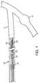
- FIG. 1is a side view of the distal end of a system according to the invention, disposed within a vessel of a subject.
- FIG. 2is a side view of a device according to the invention after the device has been deployed within the vessel.
- FIG. 3illustrates a side view of a device according to the invention, where the device is in its primary configuration.
- FIG. 4illustrates a cutaway side view of a device according to the invention, where the device is in its primary configuration.
- FIG. 5illustrates a plan view of an alternative embodiment according to the invention, in its deployed configuration, outside of a vessel of a subject.
- FIG. 6illustrates a side view of the embodiment of FIG. 5 , deployed within a vessel of a subject.
- a system 10is shown disposed within a vessel V of a subject.
- Vessel Vis a branch of or a feeder vessel to a vessel having an aneurysm A.
- System 10includes coil 12 .
- delivery catheter 15is an elongate tubular catheter.
- Pusher 18 , coil 12 and pull wire 20are disposed within delivery catheter 15 .
- Delivery catheter 15is preferably formed of a polymeric material such as Pebax nylon, urethane, PTFE, Polyimide, metals such as Stainless Steel, Platinum, etc., or other suitable material.
- Pull wire 20extends the length of delivery catheter 15 from its distal end, through its interior, and to its proximal end, where it can be manipulated by a medical practitioner who is performing the procedure to delivery coil 12 .
- coil 12Prior to the procedure, coil 12 is chilled to or below its shape transition temperature and loaded into the distal end of delivery catheter 15 .
- coil 12While disposed within delivery catheter 15 , coil 12 is in an elongate configuration known as its primary configuration. Delivery catheter 15 constrains coil 12 in this primary configuration. Delivery catheter 15 is introduced into the vasculature via an incision, and then tracked to the site where occlusion is desired.
- pusher 18will be advanced distally within delivery catheter 15 in order to advance coil 12 to the distal tip of delivery catheter 15 .
- Pull wire 20then acts in conjunction with proximal retention element 25 , and the wall of delivery catheter 15 , to retain coil 12 in the distal end of delivery catheter 15 until the precise moment that deployment of coil 12 is desired.
- coil 12Following release of coil 12 from delivery catheter 15 , coil 12 will transition from its primary, generally linear configuration, to its secondary configuration, as pictured in FIG. 2 . In its secondary configuration, coil 12 forms a tightly wound structure that anchors in vessel V. Delivery catheter 15 (and consequently pusher 18 and pull wire 20 , not visible in FIG. 2 ), can then be withdrawn proximally from vessel V. Coil 12 remains implanted within vessel V and prevents blood flow through vessel V, thereby preventing blood flow to a branch vessel having an aneurysm A. As a consequence, vessel V is occluded and sacrificed in order to achieve a therapeutic objective.
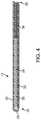
- FIG. 3is a side view of an occlusion coil according to the invention.
- Coil 12is shown in its primary configuration, also referred to as its delivery configuration.
- Coil 12is illustrated outside of a delivery catheter, yet in its primary configuration so that its features can be more easily viewed.
- Coil 12can be described while viewing FIG. 3 from left to right, with its proximal end 26 on the left side of the figure and its distal end 28 on the right.
- Proximal retention element 25is visible at proximal end 26 .
- outer coil 30and its numerous windings 31 are also visible.
- Outer coil 30extends the length of coil 12 , from its proximal end 26 to its distal end 28 .
- Outer coil 30may be constructed from any number of compositions having suitable biocompatibility and performance characteristics. Suitable materials include superelastic Nitinol, platinum, stainless steel, or polymers, including shape memory polymers. Further, materials such as Tungsten, Iridium, and others may be added to confer radio opacity. In the example of coil 12 , outer coil 30 is constructed of a Platinum/Tungsten wire of between 0.0015-0.0025 inches thick.
- FIG. 4is a cut-away side view of coil 12 .
- coil 12is a quite lengthy device that is not drawn to scale in FIG. 4 , in order that the features of coil 12 can be more easily viewed.
- outer coil 30extends the length of coil 12 .
- inner coil 32Disposed within outer coil 30 is optional inner coil 32 , which also extends the length of coil 12 .
- Outer coil 30 and inner coil 32are of similar structure, and may be constructed of either similar or dissimilar materials.
- Inner coil 32may be constructed of any of the materials listed above in the description of inner coil 30 .
- Inner coil 32prevents lateral displacement of successive windings 31 (which are more easily viewed in FIG. 3 ) and plastic deformation of outer coil 30 during the delivery process, and insures that coil 12 can be retracted into a delivery catheter even after deployment of coil 12 .
- stretch resistant member 34Disposed within inner coil 32 and visible in the cut away view of FIG. 4 is stretch resistant member 34 .
- Stretch resistant member 34extends the length of coil 12 , but in alternative embodiments, it may be shorter than coil 12 .
- Stretch resistant member 34terminates in proximal retention element 25 at proximal end 26 , and terminates at the opposite end, or distal end 28 .
- a stretch resistant member according to the inventionmay be constructed from any number of compositions having suitable biocompatibility and shape memory characteristics. Suitable materials include superelastic Nitinol, platinum, stainless steel, or polymers, including shape memory polymers, and any combination of the foregoing.
- the materials used in the construction of a stretch resistant member according to the inventionare generally fabricated into an elongate member such as a wire, filament, braid, cable, or any comparable elongate structure. The terms wire and filament are used interchangeably herein.
- a stretch resistant member according to the inventionserves two purposes. Firstly, it prevents stretching and/or permanent plastic deformation of coil 12 upon retraction of coil 12 . Secondly, it may confer the secondary configuration, or deployment configuration upon coil 12 . Alternatively, or in addition, outer coil 30 and/or inner coil 32 may confer a secondary shape on coil 12 .
- stretch resistant member 34is constructed of two components, which will be described in greater detail below. Before assembly of coil 12 , a secondary configuration is conferred upon stretch resistant member 34 . Due to the shape memory properties of the materials from which stretch resistant member 34 is constructed, stretch resistant member 34 will revert to this secondary configuration when it is not constrained by a catheter, sheath, packaging, or other constraint.
- stretch resistant member 34upon delivery of coil 12 within the subject's vasculature, stretch resistant member 34 returns to this secondary configuration. Because stretch resistant member 34 is disposed within the central lumen of coil 12 , it imparts its shape to coil 12 . Stretch resistant member is therefore responsible for reconfiguring coil 12 from its primary, or delivery configuration, to its deployment configuration, which is necessary for the effectiveness of the occlusive coil 12 .
- Stretch resistant member 34is formed from two components, first member 36 and second member 38 .
- a stretch resistant membermay be constructed of a single member that is tapered to define a larger diameter end and a smaller diameter end.
- first member 36extends the length of stretch resistant member 34 , is constructed from 0.00125 inch Nitinol wire.
- First member 36may be constructed from Nitinol wire that is between 0.00125-0.0025 inches.
- Second member 38is coupled to an end of first member 36 . Though variations in length are within the scope of the invention, second member 38 extends approximately one third of the length of stretch resistant member 34 .
- Second member 38is constructed of Nitinol wire of 0.0015-0.0030 inch, but according to the invention may be constructed of any of the materials listed above in relation to the description of stretch resistant member 34 , either alone or in combination.
- second member 38is constructed of a suitable polymer such as polyethylene terephthalate (PET), and is of double width.
- PETpolyethylene terephthalate
- a single width of a second membermay be coupled to a first member.
- Second member 38because it is coupled to first member 36 , essentially increases the thickness of stretch resistant member 34 along the length of second member 38 .
- second member 38By increasing the thickness of stretch resistant member 34 , second member 38 thereby stiffens stretch resistant member 34 along the length of second member 38 . Consequently, stretch resistant member 34 has a relatively stiffer coil loop along the length of second member 38 , and a relatively soft coil along the length of the segment which is defined solely by first member 36 . The stiffer loop exerts greater outward radial force on the vessel wall.
- Second member 38is disposed at the distal end of first member 36 .
- a second membermay be coupled to the proximal end of a first member.
- coil 12is more stiffly coiled at its distal end 28 . This stiffer distal coil exerts greater outward radial force within the vessel, and serves to anchor coil 12 more effectively within the vessel.
- the softer proximal segmentserves to fill the distal anchoring segment defined by second member 38 , and coil 12 effectively occludes the subject vessel.
- FIG. 5illustrates a plan, or topside view of coil 50 in its deployed configuration, outside a vessel of a subject. Similar to the embodiments described above, the embodiment illustrated in FIG. 5 also has a delivery configuration (not pictured) that is generally linear, that permits the device to be loaded into and delivered via a catheter or comparable delivery tool. Also similar to the embodiments described above, and featured most specifically in FIG. 4 , coil 50 includes a stretch resistant member (not visible in FIG. 5 ) that is disposed within the lumen formed by the helical turns 51 of coil 50 , and which confers the secondary or deployed shape upon coil 50 . The secondary configuration shown in FIG.
- Vessel occlusion coil 50has a proximal segment 52 .
- Proximal segment 52is shaped by a relatively soft or flexible wire or filamentous stretch resistant member (not visible in FIG. 5 ).
- the stretch resistant member shaping proximal segment 52is soft or flexible either because of a small diameter, a fine grind, or other processing step which produces a relatively soft filament.
- a wide range of flexibility, or softness, of the filamentis within the scope of the invention, and the term “relatively” is used here to mean relative to distal segment 54 , which will be discussed below.
- Proximal segment 52has a secondary (or deployed) configuration, outside of a vessel that is helical.
- a proximal segmentmay have a secondary configuration that is complex, similar to the secondary configuration of distal segment 54 , described in more detail below.
- a proximal segment according to the inventionmay have a straight or linear configuration. Though a wide range of outer diameters of the helix of proximal segment 52 are within the scope of the invention, in the example illustrated here, the outer diameter of proximal segment 52 is approximately 2-30 mm.
- the outer diameter of proximal segment 52is less than the outer diameter of distal segment 54 , when both proximal segment 52 and distal segment 54 are in their secondary configurations.
- Techniques for forming the secondary configuration of proximal segment 52are known in the art, and include, for example, wrapping the stretch resistant member disposed within proximal segment 52 around a mandrel and heat treating the segment so that it will return via shape memory behavior to the helical shape.
- Alternative techniques for achieving the objectiveare within the scope of the invention.
- Vessel occlusion coil 50also has a distal segment 54 , as mentioned above.
- Distal segment 54also includes, disposed within its interior and therefore not visible in FIG. 5 , a stretch resistant member that is fabricated from a wire, filament, or comparable structure that is stiffer relative to that used to fabricate proximal segment 52 .
- the stretch resistant member of distal segment 54may be formed from a wire or filament that is of greater thickness than that used to fabricate proximal segment 52 .
- distal segment 54may include, similar to that pictured in FIG. 4 above, a second wire member coupled to a first wire member, the second wire member extending only the length of distal segment 54 .
- annealingmay be undertaken with respect to the material used to fabricate the filament that forms the stretch resistant member of distal segment 54 .
- the resulting secondary structureis a stiffer three dimensional object than that of proximal segment 52 .
- distal segment 54has a secondary configuration that is more complex than the generally helical shape of proximal segment 52 .
- a distal segmentmay have a secondary configuration that is helical, similar to the secondary configuration described in more detail above, in relation to the description of proximal segment 52 .
- the deployed shape of distal segment 54is characterized as having sides 56 , top 58 , and bottom 62 . Taken together, sides 56 , top 58 , and bottom 62 generally define a cubic shape having rounded corners. Therefore, distal segment 54 can be described as having the shape of a cube.
- the term “cube”is used here to denote a three dimensional shape having several faces, and a particular embodiment according to the invention may or may not have six faces. The corners and edges of each face may be squared or rounded, curved or straight. Each face may or may not be of equal dimensions as each other face. Further, as is visible in FIG. 5 , the secondary shape of distal segment 54 includes some open “interior” space, and much of the coiled element defines the outer edges of the secondary shape of distal segment 54 .
- distal segment 54In addition to having a very different secondary shape than proximal segment 52 , distal segment 54 also has a larger outside profile or outer diameter than proximal segment 52 . For example, in the embodiment illustrated in FIG. 5 , distal segment 54 has an outer diameter of approximately 3-32 mm.
- Techniques for shaping distal segment 54include a series of steps of wrapping the stretch resistant member of distal segment 54 around a specialized mandrel or comparable tool, and heat treating the stretch resistant member so that it returns to the secondary shape imparted by the tool.
- Alternative techniques for fabricating the stretch resistant member disposed within distal segment 54are within the scope of the invention.
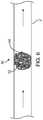
- FIG. 6illustrates the embodiment of FIG. 5 deployed within a vessel V′ of a subject in a manner similar to that described above in relation to alternative embodiments.
- Distal segment 54has anchored coil 50 within the vessel.
- the arrows of FIG. 6denote the direction of blood flow in the vessel V′.
- proximal segment 52Blood flow in vessel V′ causes the softer, smaller diameter proximal segment 52 to flow into and to fill the empty spaces within the deployed distal segment 54 . Consequently, proximal segment 52 is essentially within the interior of distal segment 54 , and is not as visible as in the illustration of FIG. 5 .
- the resulting structure of vessel occlusion coil 50is well anchored within vessel V′ and is quite dense, and consequently very effective as a vessel occlusion device.
- stiffer wire and softer wire, smaller diameter and larger diameter, and helical structure and complex structurecan be alternated or recombined in a number of combinations if it is desired for the purposes for which the vessel occlusion coil is to be used, and still be within the scope of the invention.
- an alternative embodimentmay have a distal segment that is of helical shape, and the proximal segment could be of a complex shape. Additional alternative combinations are within the scope of the invention if they are desired to achieve a particular clinical objective.
- actual outer diameters of both a distal segment and a proximal segmentmay be desired depending upon vessel size, and result in a coil that is within the scope of the invention.
Landscapes
- Health & Medical Sciences (AREA)
- Life Sciences & Earth Sciences (AREA)
- Surgery (AREA)
- Engineering & Computer Science (AREA)
- Physics & Mathematics (AREA)
- Medical Informatics (AREA)
- General Health & Medical Sciences (AREA)
- Veterinary Medicine (AREA)
- Public Health (AREA)
- Animal Behavior & Ethology (AREA)
- Biomedical Technology (AREA)
- Heart & Thoracic Surgery (AREA)
- Molecular Biology (AREA)
- Pathology (AREA)
- Biophysics (AREA)
- Cardiology (AREA)
- Nuclear Medicine, Radiotherapy & Molecular Imaging (AREA)
- Mechanical Engineering (AREA)
- Reproductive Health (AREA)
- Vascular Medicine (AREA)
- Physiology (AREA)
- Gynecology & Obstetrics (AREA)
- Pregnancy & Childbirth (AREA)
- Spectroscopy & Molecular Physics (AREA)
- Optics & Photonics (AREA)
- Surgical Instruments (AREA)
- Accommodation For Nursing Or Treatment Tables (AREA)
Abstract
Description
Claims (9)
Priority Applications (14)
| Application Number | Priority Date | Filing Date | Title |
|---|---|---|---|
| US14/154,395US10548606B2 (en) | 2011-09-30 | 2014-01-14 | Occlusive coil |
| US14/562,532US11224437B2 (en) | 2014-01-14 | 2014-12-05 | Soft embolic implant |
| PCT/US2015/011449WO2015109007A1 (en) | 2014-01-14 | 2015-01-14 | Soft embolic implant |
| EP15737622.9AEP3094269B1 (en) | 2014-01-14 | 2015-01-14 | Soft embolic implant |
| CA2936827ACA2936827C (en) | 2014-01-14 | 2015-01-14 | Soft embolic implant |
| JP2016546758AJP6914038B2 (en) | 2014-01-14 | 2015-01-14 | Flexible embolic implant |
| CN201580011977.6ACN106061411B (en) | 2014-01-14 | 2015-01-14 | soft embolic implant |
| BR112016016379ABR112016016379A8 (en) | 2014-01-14 | 2015-01-14 | soft embolic implant |
| EP22167042.5AEP4074268B1 (en) | 2014-01-14 | 2015-01-14 | Soft embolic implant |
| AU2015206524AAU2015206524B2 (en) | 2014-01-14 | 2015-01-14 | Soft embolic implant |
| IL246682AIL246682B (en) | 2014-01-14 | 2016-07-10 | Soft embolic implant |
| JP2019014397AJP7058617B2 (en) | 2014-01-14 | 2019-01-30 | Flexible embolic implant |
| JP2021070075AJP2021106937A (en) | 2014-01-14 | 2021-04-19 | Soft embolic implant |
| US17/543,179US20220087687A1 (en) | 2014-01-14 | 2021-12-06 | Soft embolic implant |
Applications Claiming Priority (2)
| Application Number | Priority Date | Filing Date | Title |
|---|---|---|---|
| US13/249,743US8641614B2 (en) | 2011-03-10 | 2011-09-30 | Umbilical probe measurement systems |
| US14/154,395US10548606B2 (en) | 2011-09-30 | 2014-01-14 | Occlusive coil |
Related Parent Applications (1)
| Application Number | Title | Priority Date | Filing Date |
|---|---|---|---|
| US13/249,743ContinuationUS8641614B2 (en) | 2011-03-10 | 2011-09-30 | Umbilical probe measurement systems |
Related Child Applications (1)
| Application Number | Title | Priority Date | Filing Date |
|---|---|---|---|
| US14/562,532Continuation-In-PartUS11224437B2 (en) | 2014-01-14 | 2014-12-05 | Soft embolic implant |
Publications (2)
| Publication Number | Publication Date |
|---|---|
| US20140128907A1 US20140128907A1 (en) | 2014-05-08 |
| US10548606B2true US10548606B2 (en) | 2020-02-04 |
Family
ID=47996516
Family Applications (1)
| Application Number | Title | Priority Date | Filing Date |
|---|---|---|---|
| US14/154,395Active2037-06-20US10548606B2 (en) | 2011-09-30 | 2014-01-14 | Occlusive coil |
Country Status (2)
| Country | Link |
|---|---|
| US (1) | US10548606B2 (en) |
| WO (1) | WO2013049837A1 (en) |
Cited By (3)
| Publication number | Priority date | Publication date | Assignee | Title |
|---|---|---|---|---|
| US20180271533A1 (en)* | 2014-12-18 | 2018-09-27 | Balt LLC | Vascular Implant System and Processes with Flexible Detachment Zones |
| US12256935B2 (en) | 2018-05-12 | 2025-03-25 | Venacore Inc. | Controlling rate of blood flow to right atrium |
| US12290265B2 (en) | 2019-04-05 | 2025-05-06 | Balt Usa, Llc | Optimized detachment systems based on leverage from electrical locus targeting and related medical devices |
Families Citing this family (21)
| Publication number | Priority date | Publication date | Assignee | Title |
|---|---|---|---|---|
| US10028747B2 (en) | 2008-05-01 | 2018-07-24 | Aneuclose Llc | Coils with a series of proximally-and-distally-connected loops for occluding a cerebral aneurysm |
| US10716573B2 (en) | 2008-05-01 | 2020-07-21 | Aneuclose | Janjua aneurysm net with a resilient neck-bridging portion for occluding a cerebral aneurysm |
| US9358140B1 (en) | 2009-11-18 | 2016-06-07 | Aneuclose Llc | Stent with outer member to embolize an aneurysm |
| CN105228688B (en) | 2013-03-15 | 2019-02-19 | 伊瑟拉医疗公司 | Vascular treatment devices and methods |
| US11547446B2 (en) | 2014-01-13 | 2023-01-10 | Trice Medical, Inc. | Fully integrated, disposable tissue visualization device |
| US11224437B2 (en) | 2014-01-14 | 2022-01-18 | Penumbra, Inc. | Soft embolic implant |
| US11344254B2 (en) | 2016-01-22 | 2022-05-31 | Welch Allyn, Inc. | Estimating hydration using capillary refill time |
| CN108697423A (en) | 2016-02-16 | 2018-10-23 | 伊瑟拉医疗公司 | The part flow arrangement of suction unit and anchoring |
| WO2017161177A1 (en) | 2016-03-17 | 2017-09-21 | Trice Medical, Inc. | Clot evacuation and visualization devices and methods of use |
| US11191927B2 (en) | 2017-07-31 | 2021-12-07 | Boston Scientific Scimed, Inc. | Dilator with engagement region |
| US11000287B2 (en) | 2017-08-15 | 2021-05-11 | Boston Scientific Scimed, Inc. | Occlusive medical device system |
| US10874402B2 (en) | 2017-10-10 | 2020-12-29 | Boston Scientific Scimed, Inc. | Detachable RF energized occlusive device |
| USD847864S1 (en) | 2018-01-22 | 2019-05-07 | Insera Therapeutics, Inc. | Pump |
| US11284902B2 (en) | 2018-02-01 | 2022-03-29 | Boston Scientific Scimed, Inc. | Method of making a vascular occlusion device |
| WO2019152775A1 (en) | 2018-02-01 | 2019-08-08 | Boston Scientific Scimed, Inc. | Medical device release system |
| US10531883B1 (en) | 2018-07-20 | 2020-01-14 | Syntheon 2.0, LLC | Aspiration thrombectomy system and methods for thrombus removal with aspiration catheter |
| US11399840B2 (en) | 2019-08-13 | 2022-08-02 | Covidien Lp | Implantable embolization device |
| US11672946B2 (en) | 2019-09-24 | 2023-06-13 | Boston Scientific Scimed, Inc. | Protection and actuation mechanism for controlled release of implantable embolic devices |
| CN112826563B (en)* | 2021-03-02 | 2025-06-17 | 微创神通医疗科技(上海)有限公司 | Medical implant and method of manufacturing the same |
| US12220139B2 (en) | 2022-03-20 | 2025-02-11 | Von Vascular, Inc. | System, devices and methods for removing obstructions in body lumens |
| US20240016497A1 (en)* | 2022-07-12 | 2024-01-18 | Medtronic Inc. | Implantable embolization device |
Citations (27)
| Publication number | Priority date | Publication date | Assignee | Title |
|---|---|---|---|---|
| US5122136A (en)* | 1990-03-13 | 1992-06-16 | The Regents Of The University Of California | Endovascular electrolytically detachable guidewire tip for the electroformation of thrombus in arteries, veins, aneurysms, vascular malformations and arteriovenous fistulas |
| US5154705A (en)* | 1987-09-30 | 1992-10-13 | Lake Region Manufacturing Co., Inc. | Hollow lumen cable apparatus |
| US5853418A (en)* | 1995-06-30 | 1998-12-29 | Target Therapeutics, Inc. | Stretch resistant vaso-occlusive coils (II) |
| CN1298287A (en) | 1998-04-28 | 2001-06-06 | 微温森公司 | Apparatus and method for vascular embolization |
| US6280457B1 (en)* | 1999-06-04 | 2001-08-28 | Scimed Life Systems, Inc. | Polymer covered vaso-occlusive devices and methods of producing such devices |
| US20040034378A1 (en) | 2001-04-10 | 2004-02-19 | Hermann Monstadt | Device for implanting occlusion spirals |
| JP2005533615A (en) | 2002-07-24 | 2005-11-10 | デンドロン・ゲー・エム・ベー・ハー | Occlusion spiral implantation device |
| US20060100661A1 (en) | 2004-11-09 | 2006-05-11 | Boston Scientific Scimed, Inc. | Vaso-occlusive devices comprising complex-shape proximal portion and smaller diameter distal portion |
| US7166122B2 (en)* | 2002-06-27 | 2007-01-23 | Boston Scientific Scimed, Inc. | Anchor assemblies in stretch-resistant vaso-occlusive coils |
| EP1889577A1 (en) | 2006-08-18 | 2008-02-20 | Cordis Development Corporation | Stretch resistant embolic coil |
| US20080103585A1 (en)* | 2004-09-22 | 2008-05-01 | Dendron Gmbh | Micro-Spiral Implantation Device |
| WO2008112435A2 (en) | 2007-03-13 | 2008-09-18 | Micro Therapeutics, Inc. | An implant including a coil and a stretch-resistant member |
| US20080306503A1 (en)* | 2006-11-20 | 2008-12-11 | Boston Scientific Scimed, Inc. | Mechanically detachable vaso-occlusive device |
| US20090062812A1 (en) | 2007-07-27 | 2009-03-05 | Microvention, Inc. | Detachable Coil Incorporating Stretch Resistance |
| US20100076479A1 (en) | 2004-01-21 | 2010-03-25 | Hermann Monstadt | Device for implanting electrically isolated occlusion helixes |
| US20100137898A1 (en) | 2008-12-02 | 2010-06-03 | Boston Scientific Scimed, Inc. | Vaso-occlusive devices with attachment assemblies for stretch-resistant members |
| WO2010096541A1 (en) | 2009-02-19 | 2010-08-26 | Biomerix Corporation | Vascular occlusion devices and methods |
| US20100268204A1 (en) | 2009-04-15 | 2010-10-21 | Microvention, Inc. | Implant Delivery System |
| US20110184454A1 (en)* | 2010-01-27 | 2011-07-28 | Penumbra, Inc. | Embolic implants |
| US20120078285A1 (en) | 2010-04-01 | 2012-03-29 | Penumbra, Inc. | Balloon catheter for intravascular therapies |
| US20120089174A1 (en) | 2010-10-12 | 2012-04-12 | Boston Scientific Scimed, Inc | Vaso-occlusive device |
| US20120209310A1 (en) | 2011-02-10 | 2012-08-16 | Stryker Nv Operations Limited | Vaso-occlusive device delivery system |
| EP2505150A1 (en) | 2011-03-31 | 2012-10-03 | Codman & Shurtleff, Inc. | Occlusive device with porous structure and stretch resistant member |
| EP2644129A2 (en) | 2012-03-30 | 2013-10-02 | DePuy Synthes Products, LLC | Embolic coil detachment mechanism with flexible distal member and coupling union |
| US20130331882A1 (en) | 2008-07-15 | 2013-12-12 | Penumbra, Inc. | Embolic coil implant system and implantation method |
| EP2674114A1 (en) | 2012-06-11 | 2013-12-18 | Acandis GmbH & Co. KG | Implant for occlusion of vascular anomalies and method for producing such an implant |
| US20140277100A1 (en) | 2011-12-02 | 2014-09-18 | Incumedx Llc | Micro-coil assembly |
Family Cites Families (4)
| Publication number | Priority date | Publication date | Assignee | Title |
|---|---|---|---|---|
| BE748832A (en)* | 1969-04-17 | 1970-09-16 | Minganti Ernesto | METHOD AND ITS DEVICE FOR HOLDING THE UMBILICAL CORD OF THE NEWBORN UNTIL ITS COMPLETE AND HYGIENIC ATROPHY |
| US20070276273A1 (en)* | 2003-09-10 | 2007-11-29 | Watson Jr Richard L | Periumbilical Infant Ecg Sensor and Monitoring System |
| US8257268B2 (en)* | 2007-07-17 | 2012-09-04 | Macleod Ainslie | Devices and systems for the prevention of sudden infant death syndrome (SIDS) |
| US7875037B2 (en)* | 2007-07-23 | 2011-01-25 | Jengstar-Md Medical Technologies Ltd. | Infant umbilical cord cardiac monitoring system and method |
- 2012
- 2012-10-01WOPCT/US2012/058341patent/WO2013049837A1/enactiveApplication Filing
- 2014
- 2014-01-14USUS14/154,395patent/US10548606B2/enactiveActive
Patent Citations (31)
| Publication number | Priority date | Publication date | Assignee | Title |
|---|---|---|---|---|
| US5154705A (en)* | 1987-09-30 | 1992-10-13 | Lake Region Manufacturing Co., Inc. | Hollow lumen cable apparatus |
| US5122136A (en)* | 1990-03-13 | 1992-06-16 | The Regents Of The University Of California | Endovascular electrolytically detachable guidewire tip for the electroformation of thrombus in arteries, veins, aneurysms, vascular malformations and arteriovenous fistulas |
| US5853418A (en)* | 1995-06-30 | 1998-12-29 | Target Therapeutics, Inc. | Stretch resistant vaso-occlusive coils (II) |
| CN1298287A (en) | 1998-04-28 | 2001-06-06 | 微温森公司 | Apparatus and method for vascular embolization |
| US6280457B1 (en)* | 1999-06-04 | 2001-08-28 | Scimed Life Systems, Inc. | Polymer covered vaso-occlusive devices and methods of producing such devices |
| JP2003501131A (en) | 1999-06-04 | 2003-01-14 | サイムド ライフ システムズ, インコーポレイテッド | Vascular closure device coated with polymer and method of making such a device |
| US20100174301A1 (en) | 1999-06-04 | 2010-07-08 | Boston Scientific Scimed, Inc. | Polymer covered vaso-occlusive devices and methods of producing such devices |
| US20040034378A1 (en) | 2001-04-10 | 2004-02-19 | Hermann Monstadt | Device for implanting occlusion spirals |
| US7166122B2 (en)* | 2002-06-27 | 2007-01-23 | Boston Scientific Scimed, Inc. | Anchor assemblies in stretch-resistant vaso-occlusive coils |
| JP2005533615A (en) | 2002-07-24 | 2005-11-10 | デンドロン・ゲー・エム・ベー・ハー | Occlusion spiral implantation device |
| US20100076479A1 (en) | 2004-01-21 | 2010-03-25 | Hermann Monstadt | Device for implanting electrically isolated occlusion helixes |
| US20080103585A1 (en)* | 2004-09-22 | 2008-05-01 | Dendron Gmbh | Micro-Spiral Implantation Device |
| US20060100661A1 (en) | 2004-11-09 | 2006-05-11 | Boston Scientific Scimed, Inc. | Vaso-occlusive devices comprising complex-shape proximal portion and smaller diameter distal portion |
| EP1889577A1 (en) | 2006-08-18 | 2008-02-20 | Cordis Development Corporation | Stretch resistant embolic coil |
| US20080306503A1 (en)* | 2006-11-20 | 2008-12-11 | Boston Scientific Scimed, Inc. | Mechanically detachable vaso-occlusive device |
| WO2008112435A2 (en) | 2007-03-13 | 2008-09-18 | Micro Therapeutics, Inc. | An implant including a coil and a stretch-resistant member |
| US20090062812A1 (en) | 2007-07-27 | 2009-03-05 | Microvention, Inc. | Detachable Coil Incorporating Stretch Resistance |
| US20130331882A1 (en) | 2008-07-15 | 2013-12-12 | Penumbra, Inc. | Embolic coil implant system and implantation method |
| US20100137898A1 (en) | 2008-12-02 | 2010-06-03 | Boston Scientific Scimed, Inc. | Vaso-occlusive devices with attachment assemblies for stretch-resistant members |
| WO2010096541A1 (en) | 2009-02-19 | 2010-08-26 | Biomerix Corporation | Vascular occlusion devices and methods |
| US20100268204A1 (en) | 2009-04-15 | 2010-10-21 | Microvention, Inc. | Implant Delivery System |
| US20110184454A1 (en)* | 2010-01-27 | 2011-07-28 | Penumbra, Inc. | Embolic implants |
| US20120078285A1 (en) | 2010-04-01 | 2012-03-29 | Penumbra, Inc. | Balloon catheter for intravascular therapies |
| US20120089174A1 (en) | 2010-10-12 | 2012-04-12 | Boston Scientific Scimed, Inc | Vaso-occlusive device |
| US20120209310A1 (en) | 2011-02-10 | 2012-08-16 | Stryker Nv Operations Limited | Vaso-occlusive device delivery system |
| EP2505150A1 (en) | 2011-03-31 | 2012-10-03 | Codman & Shurtleff, Inc. | Occlusive device with porous structure and stretch resistant member |
| US20140277100A1 (en) | 2011-12-02 | 2014-09-18 | Incumedx Llc | Micro-coil assembly |
| EP2644129A2 (en) | 2012-03-30 | 2013-10-02 | DePuy Synthes Products, LLC | Embolic coil detachment mechanism with flexible distal member and coupling union |
| US20130261659A1 (en) | 2012-03-30 | 2013-10-03 | Micrus Endovascular Llc | Embolic coil detachment mechanism with flexible distal member and coupling union |
| CN103356258A (en) | 2012-03-30 | 2013-10-23 | 德普伊新特斯产品有限责任公司 | Embolic coil detachment mechanism with flexible distal member and coupling unit |
| EP2674114A1 (en) | 2012-06-11 | 2013-12-18 | Acandis GmbH & Co. KG | Implant for occlusion of vascular anomalies and method for producing such an implant |
Non-Patent Citations (8)
| Title |
|---|
| "Office action dated Aug. 9, 2018 for U.S. Appl. No. 14/562,532". |
| "Office action dated Sep. 21, 2018 for U.S. Appl. No. 14/154,395.". |
| Arko, et al. Endovascular repair reduces early and late morbidity compared to open surgery for abdominal aortic aneurysm. J Endovasc Ther. Dec. 2002;9(6):711-8. |
| European Search Report dated Jun. 20, 2017 for EP Application No. 15737622.9. |
| International search report and written opinion dated May 5, 2015 for PCT/US2015/011449. |
| Office action dated Feb. 23, 2018 for U.S. Appl. No. 14/562,532. |
| Office action dated Jun. 12, 2019 for U.S. Appl. No. 14/562,532. |
| U.S. Appl. No. 14/562,532, filed Dec. 5, 2014, Rabkin et al. |
Cited By (3)
| Publication number | Priority date | Publication date | Assignee | Title |
|---|---|---|---|---|
| US20180271533A1 (en)* | 2014-12-18 | 2018-09-27 | Balt LLC | Vascular Implant System and Processes with Flexible Detachment Zones |
| US12256935B2 (en) | 2018-05-12 | 2025-03-25 | Venacore Inc. | Controlling rate of blood flow to right atrium |
| US12290265B2 (en) | 2019-04-05 | 2025-05-06 | Balt Usa, Llc | Optimized detachment systems based on leverage from electrical locus targeting and related medical devices |
Also Published As
| Publication number | Publication date |
|---|---|
| US20140128907A1 (en) | 2014-05-08 |
| WO2013049837A1 (en) | 2013-04-04 |
Similar Documents
| Publication | Publication Date | Title |
|---|---|---|
| US10548606B2 (en) | Occlusive coil | |
| US12167854B2 (en) | Occlusive implants with fiber-based release structures | |
| JP7584549B2 (en) | Occlusion Device | |
| US12035900B2 (en) | Devices and methods for occluding abnormal openings in a patient's vasculature | |
| US11690629B2 (en) | Systems and methods for delivery of stents and stent-like devices | |
| US11259788B2 (en) | Percutaneous catheter directed intravascular occlusion devices with retractable stabilizing wires | |
| US10893868B2 (en) | Aneurysm treatment coils | |
| AU2013271845B2 (en) | Aneurysm occlusion system and method | |
| CN109310846B (en) | Guide extension catheter with grooved pusher member segments | |
| US9615832B2 (en) | Aneurysm occlusion system and method | |
| JP4065665B2 (en) | Vascular occlusion device and manufacturing method thereof | |
| US10206685B2 (en) | Systems, devices, and methods for delivering a lumen occlusion device using distal and/or proximal control | |
| US20190142285A1 (en) | Pressure sensor, anchor, delivery system and method | |
| US8187315B1 (en) | Partial stent for treatment of a vascular aneurysm | |
| US20110184454A1 (en) | Embolic implants | |
| JP2019209152A (en) | Guidewire with atraumatic clot-circumventing configured distal end for use in endovascular medical system | |
| US20050107823A1 (en) | Anchored stent and occlusive device for treatment of aneurysms | |
| US20120016396A1 (en) | Tethered coil for treatment of body lumens | |
| JP2023517575A (en) | Neurovascular catheter with enhanced flexibility | |
| JP2018510693A (en) | Implant insertion system | |
| JP2002523125A (en) | Vaso-occlusive coil | |
| JP2019511283A (en) | Guide extension catheter with helically shaped inlet port | |
| KR20220119460A (en) | Obturator and system | |
| KR20220119461A (en) | ablation rupture occlusion system | |
| JP2023539289A (en) | Aneurysm occlusion devices, aneurysm occlusion treatment devices, and aneurysm occlusion systems |
Legal Events
| Date | Code | Title | Description |
|---|---|---|---|
| FEPP | Fee payment procedure | Free format text:ENTITY STATUS SET TO UNDISCOUNTED (ORIGINAL EVENT CODE: BIG.); ENTITY STATUS OF PATENT OWNER: LARGE ENTITY | |
| AS | Assignment | Owner name:PENUMBRA, INC., CALIFORNIA Free format text:ASSIGNMENT OF ASSIGNORS INTEREST;ASSIGNORS:HUI, DELILAH;TOMPKINS, BEN;REEL/FRAME:036293/0082 Effective date:20140122 | |
| STPP | Information on status: patent application and granting procedure in general | Free format text:FINAL REJECTION MAILED | |
| STPP | Information on status: patent application and granting procedure in general | Free format text:DOCKETED NEW CASE - READY FOR EXAMINATION | |
| STPP | Information on status: patent application and granting procedure in general | Free format text:NOTICE OF ALLOWANCE MAILED -- APPLICATION RECEIVED IN OFFICE OF PUBLICATIONS | |
| STPP | Information on status: patent application and granting procedure in general | Free format text:PUBLICATIONS -- ISSUE FEE PAYMENT VERIFIED | |
| STCF | Information on status: patent grant | Free format text:PATENTED CASE | |
| AS | Assignment | Owner name:JPMORGAN CHASE BANK, N.A., AS ADMINISTRATIVE AGENT, ILLINOIS Free format text:SECURITY INTEREST;ASSIGNOR:PENUMBRA, INC.;REEL/FRAME:052488/0785 Effective date:20200424 | |
| MAFP | Maintenance fee payment | Free format text:PAYMENT OF MAINTENANCE FEE, 4TH YEAR, LARGE ENTITY (ORIGINAL EVENT CODE: M1551); ENTITY STATUS OF PATENT OWNER: LARGE ENTITY Year of fee payment:4 | |
| AS | Assignment | Owner name:PENUMBRA, INC., CALIFORNIA Free format text:RELEASE BY SECURED PARTY;ASSIGNOR:JPMORGAN CHASE BANK, N.A., AS ADMINISTRATIVE AGENT;REEL/FRAME:066596/0706 Effective date:20240213 |