US10547211B2 - Intelligent multi-mode wireless power transmitter system - Google Patents
Intelligent multi-mode wireless power transmitter systemDownload PDFInfo
- Publication number
- US10547211B2 US10547211B2US15/786,503US201715786503AUS10547211B2US 10547211 B2US10547211 B2US 10547211B2US 201715786503 AUS201715786503 AUS 201715786503AUS 10547211 B2US10547211 B2US 10547211B2
- Authority
- US
- United States
- Prior art keywords
- power
- antenna
- ptu
- plate
- pru
- Prior art date
- Legal status (The legal status is an assumption and is not a legal conclusion. Google has not performed a legal analysis and makes no representation as to the accuracy of the status listed.)
- Expired - Fee Related, expires
Links
Images


Classifications
- H—ELECTRICITY
- H02—GENERATION; CONVERSION OR DISTRIBUTION OF ELECTRIC POWER
- H02J—CIRCUIT ARRANGEMENTS OR SYSTEMS FOR SUPPLYING OR DISTRIBUTING ELECTRIC POWER; SYSTEMS FOR STORING ELECTRIC ENERGY
- H02J50/00—Circuit arrangements or systems for wireless supply or distribution of electric power
- H02J50/10—Circuit arrangements or systems for wireless supply or distribution of electric power using inductive coupling
- H02J50/12—Circuit arrangements or systems for wireless supply or distribution of electric power using inductive coupling of the resonant type
- H—ELECTRICITY
- H02—GENERATION; CONVERSION OR DISTRIBUTION OF ELECTRIC POWER
- H02J—CIRCUIT ARRANGEMENTS OR SYSTEMS FOR SUPPLYING OR DISTRIBUTING ELECTRIC POWER; SYSTEMS FOR STORING ELECTRIC ENERGY
- H02J50/00—Circuit arrangements or systems for wireless supply or distribution of electric power
- H02J50/20—Circuit arrangements or systems for wireless supply or distribution of electric power using microwaves or radio frequency waves
- H—ELECTRICITY
- H02—GENERATION; CONVERSION OR DISTRIBUTION OF ELECTRIC POWER
- H02J—CIRCUIT ARRANGEMENTS OR SYSTEMS FOR SUPPLYING OR DISTRIBUTING ELECTRIC POWER; SYSTEMS FOR STORING ELECTRIC ENERGY
- H02J50/00—Circuit arrangements or systems for wireless supply or distribution of electric power
- H02J50/10—Circuit arrangements or systems for wireless supply or distribution of electric power using inductive coupling
- H—ELECTRICITY
- H02—GENERATION; CONVERSION OR DISTRIBUTION OF ELECTRIC POWER
- H02J—CIRCUIT ARRANGEMENTS OR SYSTEMS FOR SUPPLYING OR DISTRIBUTING ELECTRIC POWER; SYSTEMS FOR STORING ELECTRIC ENERGY
- H02J50/00—Circuit arrangements or systems for wireless supply or distribution of electric power
- H02J50/20—Circuit arrangements or systems for wireless supply or distribution of electric power using microwaves or radio frequency waves
- H02J50/23—Circuit arrangements or systems for wireless supply or distribution of electric power using microwaves or radio frequency waves characterised by the type of transmitting antennas, e.g. directional array antennas or Yagi antennas
- H—ELECTRICITY
- H02—GENERATION; CONVERSION OR DISTRIBUTION OF ELECTRIC POWER
- H02J—CIRCUIT ARRANGEMENTS OR SYSTEMS FOR SUPPLYING OR DISTRIBUTING ELECTRIC POWER; SYSTEMS FOR STORING ELECTRIC ENERGY
- H02J50/00—Circuit arrangements or systems for wireless supply or distribution of electric power
- H02J50/70—Circuit arrangements or systems for wireless supply or distribution of electric power involving the reduction of electric, magnetic or electromagnetic leakage fields
- H—ELECTRICITY
- H02—GENERATION; CONVERSION OR DISTRIBUTION OF ELECTRIC POWER
- H02J—CIRCUIT ARRANGEMENTS OR SYSTEMS FOR SUPPLYING OR DISTRIBUTING ELECTRIC POWER; SYSTEMS FOR STORING ELECTRIC ENERGY
- H02J50/00—Circuit arrangements or systems for wireless supply or distribution of electric power
- H02J50/90—Circuit arrangements or systems for wireless supply or distribution of electric power involving detection or optimisation of position, e.g. alignment
- H02J7/025—
- H02J7/027—
- H04B5/0037—
- H04B5/0075—
- H04B5/0093—
- H—ELECTRICITY
- H04—ELECTRIC COMMUNICATION TECHNIQUE
- H04B—TRANSMISSION
- H04B5/00—Near-field transmission systems, e.g. inductive or capacitive transmission systems
- H04B5/20—Near-field transmission systems, e.g. inductive or capacitive transmission systems characterised by the transmission technique; characterised by the transmission medium
- H04B5/24—Inductive coupling
- H04B5/26—Inductive coupling using coils
- H04B5/266—One coil at each side, e.g. with primary and secondary coils
- H—ELECTRICITY
- H04—ELECTRIC COMMUNICATION TECHNIQUE
- H04B—TRANSMISSION
- H04B5/00—Near-field transmission systems, e.g. inductive or capacitive transmission systems
- H04B5/70—Near-field transmission systems, e.g. inductive or capacitive transmission systems specially adapted for specific purposes
- H04B5/79—Near-field transmission systems, e.g. inductive or capacitive transmission systems specially adapted for specific purposes for data transfer in combination with power transfer
- H—ELECTRICITY
- H01—ELECTRIC ELEMENTS
- H01Q—ANTENNAS, i.e. RADIO AERIALS
- H01Q19/00—Combinations of primary active antenna elements and units with secondary devices, e.g. with quasi-optical devices, for giving the antenna a desired directional characteristic
- H01Q19/10—Combinations of primary active antenna elements and units with secondary devices, e.g. with quasi-optical devices, for giving the antenna a desired directional characteristic using reflecting surfaces
- H—ELECTRICITY
- H01—ELECTRIC ELEMENTS
- H01Q—ANTENNAS, i.e. RADIO AERIALS
- H01Q3/00—Arrangements for changing or varying the orientation or the shape of the directional pattern of the waves radiated from an antenna or antenna system
- H01Q3/02—Arrangements for changing or varying the orientation or the shape of the directional pattern of the waves radiated from an antenna or antenna system using mechanical movement of antenna or antenna system as a whole
- H01Q3/04—Arrangements for changing or varying the orientation or the shape of the directional pattern of the waves radiated from an antenna or antenna system using mechanical movement of antenna or antenna system as a whole for varying one co-ordinate of the orientation
- H—ELECTRICITY
- H01—ELECTRIC ELEMENTS
- H01Q—ANTENNAS, i.e. RADIO AERIALS
- H01Q7/00—Loop antennas with a substantially uniform current distribution around the loop and having a directional radiation pattern in a plane perpendicular to the plane of the loop
- H—ELECTRICITY
- H01—ELECTRIC ELEMENTS
- H01Q—ANTENNAS, i.e. RADIO AERIALS
- H01Q9/00—Electrically-short antennas having dimensions not more than twice the operating wavelength and consisting of conductive active radiating elements
- H01Q9/04—Resonant antennas
- H01Q9/30—Resonant antennas with feed to end of elongated active element, e.g. unipole
- H01Q9/42—Resonant antennas with feed to end of elongated active element, e.g. unipole with folded element, the folded parts being spaced apart a small fraction of the operating wavelength
- H—ELECTRICITY
- H02—GENERATION; CONVERSION OR DISTRIBUTION OF ELECTRIC POWER
- H02M—APPARATUS FOR CONVERSION BETWEEN AC AND AC, BETWEEN AC AND DC, OR BETWEEN DC AND DC, AND FOR USE WITH MAINS OR SIMILAR POWER SUPPLY SYSTEMS; CONVERSION OF DC OR AC INPUT POWER INTO SURGE OUTPUT POWER; CONTROL OR REGULATION THEREOF
- H02M1/00—Details of apparatus for conversion
- H02M1/12—Arrangements for reducing harmonics from AC input or output
Definitions
- the present disclosurerelates to providing wireless power to electric or electronic devices, and more particularly to improving the wireless transfer of power to devices for charging and/or sustaining power to those devices' loads.
- a devicein certain embodiments, includes a processor configured to identify a power receiving device and to determine a range configuration relative to the power receiving device.
- the devicealso includes a first antenna configured to emit a propagating radiation at a selected frequency and in a selected direction, and a first power transmitting circuit configured to provide a signal at the selected frequency to the first antenna when the processor identifies the power receiving device within a far field configuration from the device.
- the devicealso includes a plate, configured to couple a ground terminal of the first power transmitting circuit with the first antenna and including a planar surface and at least an extension angled in a direction of increased directivity of the propagating radiation.
- a methodin certain embodiments, includes selecting a radio-frequency antenna, mechanically coupling a plate to the radio-frequency antenna in a first antenna assembly, and electrically coupling the plate with a ground terminal in a radio-frequency transmitter circuit that provides a radio-frequency signal to the radio-frequency antenna to transmit to a power receiving unit.
- the methodalso includes identifying a degree of anisotropy in an electromagnetic field emitted by the radio-frequency antenna, and adjusting a location and a geometry of the radio-frequency antenna and a location and a geometry of the plate to increase a directivity of the radio-frequency signal in a selected direction, based on the degree of anisotropy in the electromagnetic field emitted by the radio-frequency antenna.
- a methodin certain embodiments, includes identifying, with a power transferring unit, a power receiving unit in a proximity of the power transferring unit, and determining whether the power receiving unit is in a near field range or in a far field range of the power transferring unit.
- the methodalso includes receiving a power status information from the power receiving unit, and generating, in the power transferring unit and based on the power status information, a directed energy signal from the power transferring unit to the power receiving unit, when the power receiving unit is within a far range of the power transferring unit.
- the methodalso includes generating, in the power transferring unit and based on the power status information, an inductively coupled field that is resonant with the power receiving unit, when the power receiving unit is within at least a near field range of the power transferring unit.
- a devicein certain embodiments, includes a means to store instructions and a means to execute the instructions.
- the means to execute the instructionsexecutes the instructions, it causes the device to perform a method including steps to identify, with a power transferring unit, a power receiving unit in a proximity of the power transferring unit, and to determine whether the power receiving unit is in a near field range or in a far field range of the power transferring unit.
- the means to execute instructionsalso executes instructions to receive a power status information from the power receiving unit, and to generate, in the power transferring unit and based on the power status information, a directed energy signal from the power transferring unit to the power receiving unit, when the power receiving unit is within a far range of the power transferring unit.
- the means to execute instructionsalso executes instructions to generate, in the power transferring unit and based on the power status information, an inductively coupled field that is resonant with the power receiving unit, when the power receiving unit is within at least a near field range of the power transferring unit.
- FIG. 1Ais a schematic illustration of a system for providing intelligent wireless power to a device load, including a power transfer unit (PTU) and a power receiving unit (PRU), according to some embodiments.
- PTUpower transfer unit
- PRUpower receiving unit
- FIG. 1Bis a schematic illustration of a PTU including a USB socket for an external power supply, according to some embodiments.
- FIG. 2is a schematic illustration of a PTU including a voltage source to provide a voltage reference input, according to some embodiments.
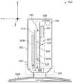
- FIG. 3is a schematic illustration of a PTU enshrouded in a cylindrical body, according to some embodiments.
- FIGS. 4A-Billustrate a cross section view and a plan view of a ground plate, according to some embodiments.
- FIGS. 5A-Billustrate perspective views of RF antenna assemblies for a PTU, according to some embodiments.
- FIGS. 6A-Billustrate electromagnetic propagation results from the RF assemblies of FIGS. 5A-B , respectively, according to some embodiments.
- FIGS. 7A-Cillustrate perspective views of RF antenna assemblies in a planar inverted-F (PIFA) configuration, according to some embodiments.
- PIFAplanar inverted-F
- FIGS. 8A-Cillustrate electromagnetic propagation results from the RF antenna assemblies of FIGS. 7A-C , according to some embodiments.
- FIGS. 9A-Billustrate perspective views of RF antenna assemblies in a monopole configuration, according to some embodiments.
- FIGS. 10A-Billustrate electromagnetic propagation results from the RF antenna assemblies of FIGS. 9A-B , respectively, according to some embodiments.
- FIGS. 11A-Cillustrate perspective views of RF antenna assemblies in a larger monopole configuration relative to that of FIGS. 9A-B , according to some embodiments.
- FIGS. 12A-Cillustrate electromagnetic propagation results from the RF antenna assemblies of FIGS. 11A-C , according to some embodiments.
- FIG. 13illustrates a chart including a spectral transmission curve for a RF antenna in a PTU, according to some embodiments.
- FIG. 14illustrates a chart including spectral transmission curves for different temperatures in a PTU, according to some embodiments.
- FIG. 15illustrates a mobile device casing having slots and related features that may interfere with a power transfer process, according to some embodiments.
- FIG. 16illustrates a flow chart of a method for designing a RF antenna for use in a PTU to provide a directed energy signal to a PRU.
- FIG. 17illustrates a flow chart of a method for designing a RF antenna for use in a PTU to provide an inductively coupled field to a PRU.
- FIG. 18is a flowchart illustrating steps in a method for managing, from a power receiving unit, a power transfer from a PTU, according to some embodiments.
- some embodiments as disclosed hereinprovide a central power transmitting unit that can wirelessly access multiple mobile devices (e.g., cell phones, laptops, notepads, and the like) within the enclosure of a car by maximizing the charge points throughout the vehicle. Accordingly, in embodiments as disclosed herein a driver can focus on the road rather than in looking for a plug to connect a power cord for a device, thereby enhancing road safety and the convenience of multiple charging points.
- mobile devicese.g., cell phones, laptops, notepads, and the like
- the present disclosureis embodied as a system and method of providing wireless power intelligently to a device load. Accordingly, embodiments consistent with the present disclosure transmit a directed power signal wirelessly from a power transferring unit (PTU) to a power receiving unit (PRU) in a first mode of operation (e.g., when the PRU is in the proximity of a far field range of the PTU).
- PTUpower transferring unit
- PRUpower receiving unit
- embodiments as disclosed hereininclude generating a field (e.g., a resonant magnetic field) wirelessly and inductively coupled to the PRU at a resonant frequency of a receiver circuit in a second mode of operation (e.g., when the PRU is in the proximity of a near field range of the PTU).
- a power transfer from the PTU to the PRUis managed selectively and efficiently.
- Embodiments as disclosed hereindeliver power as desired in the first mode of operation, the second mode of operation, or a combination of both modes simultaneously.
- embodiments as disclosed hereintake into consideration a power requirement of the PRU, and its range relative to the PTU.
- a PTUmay transfer power to a plurality of PRU's, sorted according to a prioritization that takes into account the power requirements and range of each PRU relative to the PTU.
- the PTUincludes a far field transmitter configured to wirelessly transmit a directed power signal.
- the PTUalso includes a source resonator configured to generate a resonant magnetic field for inductively coupling power to the PRU in the near field range.
- the PRUincludes a far field receiver configured to wirelessly receive the directed power signal transmitted from the far field transmitter.
- the PRUmay also include a capture resonator configured to inductively capture resonant magnetic power in the near field generated by the source resonator.
- Some embodimentsinclude a method of managing multimode transfer of wireless power.
- the methodincludes optimizing the wireless transfer of power from the PTU in at least the first mode of operation, the second mode of operation, or the two modes of operation simultaneously.
- the methodincludes capturing and receiving the optimized power transferred wirelessly over varying distances by one or more power receiving units (PRU's).
- PRU'spower receiving units
- Some embodimentsinclude a micro-computer circuit (MCC) configured to dynamically update a status of a range configuration between the PRU and the PTU to maximize the amount of power transferred between the devices in a dual mode, when available.
- MCCmicro-computer circuit
- some embodimentsinclude a power harvesting configuration that exploits the large amount of unused digital data propagating at RF frequencies wirelessly to convert the digital signals into power transferred to the PRU.
- the MCCincludes the reception and availability of the digital signals for harvesting. Moreover, in some embodiments the MCC is further configured to prioritize the desire for power for one or more PRU's in close proximity of the PTU. Thus, the load on the PTU is optimized for the needs of the one or multiple PRU's benefiting from the power transfer.
- the present disclosureaddresses the shortcomings of existing single-mode wireless power delivery systems such as low power transfer from a far field source or the limited spatial freedom of near field power transfer inherent to these technologies.
- embodiments consistent with the present disclosureobviate a need for traditional wired or cabled power delivery methods.
- Advantages of the present disclosureinclude increased efficiency, added redundancy for applications where critical loss of available power could be detrimental to the user and optional spatial versatility when lower power transfer rates are acceptable while providing power to or charging an electric or electronic device.
- the total output of an antenna assembly for a PTU as disclosed hereinbe less than one Watt, with a power about 6 dBi maximum directional gain.
- Some embodiments of a PTU consistent with the present disclosuremay include a higher directivity and performance variation depending on design details. Further, the mechanical consistency of the antenna assembly may be adjusted according to a desired performance specification.
- Embodiments as disclosed hereinmay include a ceramic-based (e.g., high dielectric constant) antenna with additional mechanical modifications to improve directivity of power transmission. Further, some embodiments include similar mechanical modifications combined with alternative antenna designs. Based on the specific application, a specific antenna design may be selected according to a desired transmission pattern. The transmission pattern may include a specific direction for maximum power transmission (e.g., directivity) and a range of directions that provide enhanced power transmission (including the maximum power transmission).
- a specific direction for maximum power transmissione.g., directivity
- range of directionsthat provide enhanced power transmission (including the maximum power transmission).
- FIG. 1Aillustrates a system for providing intelligent wireless power to a device load in accordance with the principles of the present disclosure, designated generally as 10 .
- the system 10includes PTU 12 and PRU 14 .
- PTU 12is configured to transmit a directed power signal 16 wirelessly in a first mode of operation to PRU 14 .
- PTU 12is further configured to generate an inductively coupled field (e.g., a resonant magnetic field) 18 wirelessly in a second mode of operation.
- PRU 14is configured to receive the directed power signal 16 from PTU 12 when PRU 14 is in the far field range of PTU 12 .
- PRU 14is also configured to inductively couple a magnetic field thereof to the inductively coupled field 18 in the second mode when PRU 14 is in the proximity of a near field range of PTU 12 , as will be explained in detail below.
- PTU 12includes a far field transmitter 22 configured to wirelessly transmit the directed power signal 16 and a source resonator 24 configured to generate the inductively coupled field 18 .
- PTU 12includes a micro-controller circuit (MCC) 29 operatively connected to a power source 30 and configured to intelligently induce wireless transfer of power within the near field, far field or both as required, and to manage the distribution and priorities of power transfer.
- MCCmicro-controller circuit
- a communications circuit 32is configured to establish communication between PTU 12 and PRU 14 .
- PTU amplifier/rectifier circuits 34 a and 34 bare configured to convert the power for the source resonator 24 and the far field transmitter 22 , respectively.
- source resonator 24includes a source coil 42 operatively connected to an impedance matching circuit (IMC) 44 .
- a far field transmitter 22includes a signal conversion module 50 and a far field transmitter antenna(s) 52 whereby the amplified/rectified power is converted by the signal conversion module 50 to a power signal suitable for transmission via a far field transmitter antenna(s) 52 .
- the transmitters and resonatorsconvert RF power to power signals at an Industrial, Scientific, and Medical (ISM) frequency band appropriately optimized for the application of the system and in accordance with regulatory rules and laws governing such wireless operations.
- ISMIndustrial, Scientific, and Medical
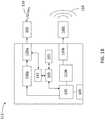
- FIG. 1Bis a schematic illustration of a PTU 112 , according to some embodiments.
- PTU 112is configured to wirelessly transmit a directed power signal 116 using an antenna 165 (e.g., a RF antenna) to PRU 14 located at least within a far field range from PTU 112 , in a first mode of operation (e.g., “far range” mode, a).
- Antenna 165may be a far field transmitter configured to wirelessly transmit the directed power signal to PRU 14 located within the far range of PTU 112 .
- Directed power signal 116may include a RF propagating signal suitably tuned to a resonant receiver circuit in PRU 14 (e.g., at 915 MHz).
- the directed power signalmay also include a selected directionality for the RF propagating signal to make more efficient the power transfer between PTU 112 and the PRU 14 .
- PTU 112may also be configured to generate an inductively coupled field 118 with a Tx resonator 160 t , which is resonant with a receiver circuit in PRU 14 .
- Tx resonator 160 tgenerates an inductively coupled field 118 .
- Inductively coupled field 118may include a RF modulated magnetic field wirelessly transmitted across a near range in a second mode of operation of PTU 112 (e.g., “near field” mode, b).
- Tx resonator 160 tis configured to generate a magnetic induction field (e.g., inductively coupled power signal 118 ) modulated at approximately 6.78 MHz.
- the magnetic fieldmay be modulated at a lower frequency, e.g., 1 MHz, 100's of kHz, or even lower frequencies such as between 90-300 kHz, depending on range, power, and other design configurations.
- PTU 112further includes a micro-controller circuit (MCC) 100 operatively coupled to a memory circuit 155 and configured to cause PTU 12 to perform a wireless transfer of power in the far field mode of operation (a), the near field mode of operation (b) or both, as required.
- MCC 100may be as MCC 29 , described in detail above.
- MCC 100is configured to manage the distribution and priorities of a power transfer between PTU 12 and multiple PRUs 14 .
- PTU 112includes a communications circuit 132 (e.g., communications circuit 32 ) configured to communicate information between PTU 112 and PRU 14 .
- the RF power signalis provided by a RF power supply 130 to either one of amplifier 110 a or amplifier 110 b (hereinafter, collectively referred to as “amplifiers 110 ”).
- RF power supply 130is controlled by MCC 100 .
- Amplifier 110 a and passively tuning IC (PTIC) 120 aare configured to provide an amplified RF signal to antenna 165 , the amplified RF signal tuned to a frequency that is resonant with a receiver circuit in PRU 14 .
- PTIC 120includes a coil operatively coupled with an impedance matching circuit (IMC).
- IMCimpedance matching circuit
- amplifier 110 b and PTIC 120 bare configured to provide an amplified RF signal to Tx resonator 160 t .
- PTIC 120 a and PTIC 120 bwill be hereinafter, collectively referred to as PTICs 120
- amplifiers 110 a and 110 bwill be collectively referred to, hereinafter, as amplifiers 110 .
- PTICs 120may be configured to amplify a signal, or may be integrated with amplifiers 110 to provide a tuned, amplified signal.
- PTU 112may be wired to an external power supply (e.g., a computer, a centralized service station, a wall power, and the like) and configured to receive power resources. Accordingly a USB-Socket 105 may couple PTU 112 with the external power supply.
- an external power supplye.g., a computer, a centralized service station, a wall power, and the like
- a USB-Socket 105may couple PTU 112 with the external power supply.
- FIG. 2is a schematic illustration of a PTU 212 , according to some embodiments.
- PTU 212includes antenna 275 , consistent with the present disclosure (e.g., antenna 165 ).
- MCC 100couples power signal (e.g., at 3.3V and +12 C) to a transmitter 222 (e.g., an application-specific IC, ASIC).
- MCC 100provides a control signal to LED driver # 1 250 - 1 and to LED driver # 2 250 - 2 (hereinafter, collectively referred to as “LED drivers 250 ”).
- LED drivers 250provide signals to turn on/off RGB emitters 255 - 1 through 255 - 4 (hereinafter, collectively referred to as “RGB emitters 255 ”). Accordingly, RGB emitters 255 light up when PTU 212 is ready for wirelessly transferring power to a mobile device (e.g., PRU 14 ).
- transmitter 222transmits a power signal (e.g., at 5V and 6.78 MHz) to gate driver 230 .
- a matching feedback circuit 240provides adjustable tuning.
- a protection circuit 290may include an over voltage protection (OVP) circuit, an over charge protection (OCP) circuit, or an over temperature protection (OTP) circuit. Protection circuit 290 also provides an indication of local faults to transmitter 222 .
- the local faultsmay include an excess voltage, excess charge, or excess temperature. Fault conditions as above may be desirably avoided when transmitter 222 operates in resonance.
- protection circuit 290prevents damage to a power amplifier 210 from feedback if there is too much RF reflection from RF receiver 260 t
- OVP circuitprevents over-coupling and damage to a device and system components in a resonant magnetic environment (e.g., at 13.56 MHz, 6.78 MHz, or lower frequencies).
- An input power 201may be used to provide a power signal (e.g., at 18V and 3-5 A) to a source voltage block 203 (e.g., AUX VDD), which sends a power signal (e.g., at 5V) to transmitter 220 , to be transferred to the PRU through RF antenna 265 (e.g., at 915 MHz).
- Transmitter 220e.g., a RF transmitter
- a source voltage source 205provides a power signal (e.g., at 6V and 2 A) to gate driver 230 .
- Power amplifier 210amplifies the RF signal from gate driver 230 .
- the amplified RF signalis passed through an electromagnetic interference (EMI) filter 245 to remove spurious frequency components.
- EMIelectromagnetic interference
- Matching network switch 242directs the amplified and filtered RF signal to a specific network or network device located within range of PTU 212 .
- RF antenna 220transmits an inductively coupled power signal to the device in the matching network.
- FIG. 3is a schematic illustration of a PTU 312 , according to some embodiments.
- a processor 300is configured to identify a PRU in the vicinity of PTU 312 (e.g., PRU 14 ) and to determine a range configuration relative to the PRU.
- Antenna 365is configured to emit a propagating radiation (e.g., directed power signals 16 and 116 ) at a selected frequency and in a selected direction.
- PTU 312also includes a power transmitting circuit 320 a configured to provide a signal at the selected frequency to antenna 365 when processor 300 identifies the PRU within a far field configuration from PTU 312 .
- a ground plate 310is configured to couple a ground terminal 322 of power transmitting circuit 320 a with antenna 365 .
- Antenna 365is coupled with power transmitting circuit 320 a through a connector 325 (e.g., a coaxial cable).
- Antenna 360 tis configured to generate an inductively coupled field at a second frequency to provide a power signal (e.g., inductively coupled fields 18 , and 118 ) to the PRU when processor 300 identifies the PRU within a near field configuration from PTU 312 .
- antenna 360 tis an inductive coil and receives the power signal from a second power transmitting circuit 320 b mounted on a substrate 315 (e.g., a resonant PCBA) configured to provide a signal to antenna 360 t at a second frequency.
- antenna 360 tmay be formed in a plate substantially orthogonal to antenna assembly 367 . Power transmitting circuit 320 a and power transmitting circuit 320 b will be collectively referred to, hereinafter, as “power transmitting circuits 320 .”
- ground plate 310 , power transmitting circuits 320 , and substrate 315include substantially co-planar surfaces that fit along a diameter of a cylindrical body 301 . More generally, body 301 may have any geometry according to the specific application and manufacturing capabilities for PTU 312 .
- a button 340may be included to manually activate or de-activate antenna 360 t.
- LED driver 350is configured to turn ‘on’ or ‘of’ a LED 355 to indicate when PTU 312 is operating in a directed energy, power transfer mode (e.g., directed power transfer mode, a) or in a second power transfer mode (e.g., inductively coupled power transfer, b) based on the range configuration determined by processor 300 .
- a directed energy, power transfer modee.g., directed power transfer mode, a
- a second power transfer modee.g., inductively coupled power transfer, b
- PTU 312includes a matching network switch 342 coupled with the power transmitting circuit 320 a and configured to provide multiple signals at multiple frequencies within a selected bandwidth for antenna 365 , wherein each of the multiple signals is directed to a different power receiving unit.
- antenna 365 and ground plate 310form an antenna assembly 367 .
- antenna assembly 367is mounted on a rotational mount 370 having a rotation axis in the planar surface of ground plate 310 . Accordingly, rotational mount 370 may be configured to rotate about the rotation axis, thereby rotating antenna assembly 367 in a plane (e.g., YZ plane in FIG. 3 ) substantially orthogonal to the planar surface of the plate (e.g., XZ plane in FIG. 3 ). In some embodiments, antenna assembly 367 may be rotated by rotating the entire enclosure (e.g., body 301 ).
- PTU 312may be configured to track the movement of a PRU by sensors, or direct communication with the PRU. Accordingly, rotational mount 370 may rotate (e.g., via a brushless motor or servo) to maximize power transfer and efficiency to the PRU. Such configurations may be desirable when the PRU is expected to be in movement, while charging.
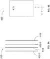
- FIGS. 4A-Billustrate a cross section view and a plan view of a ground plate 410 , respectively, according to some embodiments.
- ground plate 410includes a multilayer stack including a first trace layer 412 - 1 , power plane 414 , a second trace layer 412 - 2 (hereinafter, collectively referred to as “trace layers 412 ”), and a ground layer 416 coupled to ground.
- FIG. 4Billustrates an embodiment wherein ground plate 410 includes a planar surface 415 .
- planar surface 415fits within a cross section along a diameter of cylindrical body 301 enshrouding antenna assembly 367 .
- the XZ planeis consistent with the XYZ coordinate system in FIG. 3 .
- FIGS. 5A-Billustrate perspective views of antenna assemblies 500 A and 500 B for a PTU, according to some embodiments.
- antenna assemblies 500 A and 500 Bwill be collectively referred to as “antenna assemblies 500 .”
- Antenna assemblies 500include antenna 565 .
- Antenna 565may include a ceramic dielectric surrounding a coiled conductor in a plane parallel to the planar surface of the plate.
- ground plate 510includes top and side extensions 515 angled in a direction of increased directivity of the propagating radiation.
- ground contacts 521provide electrical coupling between the ground of a power transmitting circuit 520 and a ground plate 510 (along the entire back of a planar surface in ground plate 510 ).
- antenna assemblies 500include a coated bottom surface 525 coated with metal to ground the back PCB to the bottom metal plate 550 .
- bottom surface 525may be affixed with copper tape to bottom metal plate 550 .
- FIGS. 6A-Billustrate charts 600 A-B, respectively, indicating electromagnetic propagation results from antenna assemblies 500 , respectively, according to some embodiments.
- the RF frequency used in the modelingis, without limitation, about 900 MHz (e.g., 915 MHz).
- Chart 600 Aillustrates a maximum direction 601 a at about five decibels relative to isotropic (dBi) power (e.g., 5.035 dBi).
- Chart 600 Billustrates a maximum direction 601 b at about four dBi (e.g., 4.364 dBi).
- additional ground contacts 521tend to decrease the directivity of the RF radiation, while broadening the overall pattern towards the antenna side ( ⁇ Y-direction).
- a broadened patternmay be desirable in some applications to provide a greater flexibility for transferring power to the PRU.
- FIGS. 7A-Cillustrate perspective views of antenna assemblies 700 A, 700 B, and 700 C in a planar inverted-F (PIFA) configuration (hereinafter, collectively referred to as “PIFA antenna assemblies 700 ”), according to some embodiments.
- PIFA antenna assemblies 700planar inverted-F
- PIFA antenna 700 Aincludes a ground plate 710 coupled to a power transmitting circuit 720 .
- Ground plate 710includes top and side extensions 715 a , similarly to ground plate extensions described above (e.g., extensions 515 ).
- PIFA antenna 700 Bincludes a ground plate 710 with top and side extensions 715 b
- PIFA antenna 700 Cincludes ground plate 710 with side extension in FIG. 7C , for clarity) with additional ground contacts 721 .
- Side extensions 715 a and 715 bwill be collectively referred to, hereinafter, as “side extensions 715 .”
- PIFA antennas 700include a planar inverted-F architecture 765 laid on a plane substantially perpendicular to the planar surface of ground plate 710 .
- FIGS. 8A-Cillustrate charts 800 A-C, respectively, indicating electromagnetic propagation results from PIFA antenna assemblies 700 , according to some embodiments.
- the RF frequency used in the modelingis, without limitation, about 900 MHz (e.g., 915 MHz).
- Chart 800 Aillustrates a maximum direction 801 a at about four dBi (e.g., 4.450 dBi).
- Chart 800 Billustrates a maximum direction 801 b at about four dBi (e.g., 4.341 dBi).
- Chart 800 Cillustrates a maximum direction 801 c at about three dBi (e.g., 3.330 dBi).
- FIGS. 9A-Billustrate perspective views of RF antenna assemblies 900 A and 900 B, respectively, in a monopole configuration, according to some embodiments.
- RF antenna assemblies 900 A and 900 Bwill be collectively referred to, hereinafter, as “monopole assemblies 900 .”
- monopole assemblies 900may include antenna 965 having a conductive coil laid on a plane perpendicular to the planar surface of ground plate 910 including top and side extensions 915 .
- Power transmitting circuit 920includes elements similar to power transmitting circuits as disclosed herein (e.g., power transmitting circuits 520 , 720 ) such as ground contacts 921 (e.g., ground contacts 521 , and 721 ).
- FIGS. 10A-Billustrate charts 1000 A and 1000 B respectively, indicating electromagnetic propagation results from monopole assemblies 900 according to some embodiments.
- Chart 1000 Aillustrates a maximum direction 1001 a at about three dBi (e.g., 3.407 dBi). Note that, although the dBi power in chart 1000 A is somewhat lower than the previous charts (e.g., charts 600 and 800 ), maximum direction 1001 a includes two orientations, along the negative Y-axis direction, and along the positive Y-axis direction.
- dBi3.407 dBi
- Chart 1000 Billustrates a maximum direction 1001 b at about two dBi (e.g., 2.032 dBi). Note that, although the dBi power in chart 1000 B is somewhat lower than the previous charts (e.g., charts 600 and 800 ), maximum direction 1001 b includes two different azimuthal directions about the Y-axis.
- FIGS. 11A-Cillustrate perspective views of a RF antenna assemblies 1100 A, 1100 B, and 1100 C in a larger monopole configuration relative to that of FIGS. 9A-B , according to some embodiments.
- RF antenna assemblies 1100 A, 1100 B, and 1100 Cwill be collectively referred to, hereinafter, as “big monopole antenna assemblies 1100 .”
- Big monopole antenna assemblies 1100include a big monopole antenna 1165 and top and side extensions 1115 .
- Big monopole antenna 1165may include two planar surfaces 1167 - 1 and 1167 - 2 arranged perpendicularly to each other.
- planar surface 1167 - 2is disposed substantially parallel to the planar surface of conductive plate 1110 , perpendicular to planar surface 1167 - 1 .
- planar surface 1167 - 2is a conductive surface. The length and width of planar surface 1167 - 2 may be adjusted according to the desired performance of antenna 1165 .
- a ground plate 1125may be plated with a metallic surface to contact conductive plate 1110 .
- a power transmitting circuit 1120includes elements similar to power transmitting circuits as disclosed herein (e.g., power transmitting circuits 520 , 720 , and 920 ), such as ground contacts 1121 (e.g., ground contacts 521 , 721 , and 921 ).
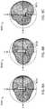
- FIGS. 12A-Cillustrate charts 1200 A-C, respectively, indicating electromagnetic propagation results from big monopole antenna assemblies 1100 , according to some embodiments.
- Charts 1200 a , 1200 b , and 1200 cwill be collectively referred to, hereinafter, as “charts 1200 .”
- Chart 1200 Aillustrates a maximum direction 1201 a at about five dBi (e.g., 5.172 dBi). Note that maximum direction 1201 a includes two orientations, along the negative Y-axis direction, and along the positive Y-axis direction.
- Chart 1200 Billustrates a maximum direction 1201 b at about five dBi (e.g., 5.637 dBi).
- Maximum direction 1201 bincludes two different azimuthal directions about the Y-axis.
- Chart 1200 Cillustrates a maximum direction 1201 c at about five dBi (e.g., 5.061 dBi).
- Maximum direction 1201 cincludes a broader azimuthal coverage about the Y-axis (in the ⁇ Y direction).
- Chart 1200 Cillustrates that in some embodiments an extension of ground plate 1110 c that may be angled in a direction of increased directivity having a hemispherical breadth in a direction orthogonal to a plane of the first antenna.
- FIG. 13illustrates a chart 1300 including a spectral transmission curve 1310 for a RF antenna in a PTU, according to some embodiments.
- the abscissae (X-axis) 1301 in chart 1300indicates the frequency of the signal provided to the antenna (e.g., in MHz), and the ordinate (Y-axis) 1302 indicates the power output of the antenna at the specified frequency.
- the unit in ordinate 1302is a logarithmic power unit (dBm).
- curve 1310has a resonance (“peak”) at 915 MHz.
- FIG. 14illustrates a chart 1400 including spectral transmission curves 1410 a , 1410 b , 1410 c , and 1410 d (hereinafter, collectively referred to as “transmission curves 1400 ”), for different temperatures in a PTU, according to some embodiments.
- the abscissae 1401 and the ordinate 1402 in FIG. 14are as described above (e.g., abscissa 1301 and ordinate 1302 ).
- Chart 1400illustrates a fragment of chart 1300 showing the maximum power transmission efficiency for the antenna. More specifically, curve 1410 a illustrates the maximum power transmission efficiency at ⁇ 40 degrees Celsius (° C.). Curve 1410 b illustrates the maximum power transmission efficiency of the antenna at 25° C. Curve 1410 c illustrates the maximum power transmission efficiency of the antenna at 85° C., and curve 1410 d illustrates the maximum power transmission efficiency of the antenna at 105° C.
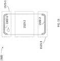
- FIG. 15illustrates a mobile device casing 1500 having slots 1502 - 1 and 1502 - 2 (hereinafter, collectively referred to as “slots 1502 ”) and related features that may interfere with a power transfer process, according to some embodiments.
- the power transfer processmay interfere with the use of the mobile device (e.g., transmission and reception of RF signals) and is something to be considered when designing a PRU around a mobile device or devices that utilize RF for communications.
- Antennas in the mobile devicemay interact with a metal casing 1500 , impacting the lifetime of a mobile device battery.
- the mobile devicemay require a higher power level for adequate transmission and reception of signals. Accordingly, the mobile device battery will tend to drain and drop calls (in the case of a cell phone or a smart phone).
- mobile device casing 1500may create electromagnetic interference (EMI) and RF noise, thus degrading signal quality, reducing network capacity and increasing the number of dropped calls. To compensate for signal quality degradation, some mobile devices increase the power usage, negatively impacting battery lifetime.
- Mobile device casing 1500includes sensitive regions 1523 - 1 , 1523 - 2 , and 1523 - 3 (hereinafter, collectively referred to as “sensitive regions 1523 ”) where antennas may be located.
- the lower frequency antennasmay use the entirety of casing 1500 to radiate (e.g., including portion 1523 - 2 ).
- Higher frequency antennasRF greater than 1.6 GHz are more localized in the radiation (e.g., in sensitive regions 1523 - 1 and 1523 - 3 )
- a selection of an antenna design for a PTU as disclosed hereinincludes performing EM simulations to select antenna architectures that are less affected by casing 1500 .
- the effect of casing 1500may be more pronounced for RF antennas operating on the 900-930 MHz frequency range (e.g., antennas 165 , 265 , 365 , 565 , 765 , 965 , and 1165 ).
- a PTU as disclosed hereinmay include a PIFA or a monopole style antenna (e.g., antennas 765 , 965 and 1165 ) may include an enhanced depth of the PCB layer relative to the planar surface of the ground plate.
- a PTUmay include an on-ground chip antenna adjusted to operate at about 915 MHz.
- a PTU as disclosed hereinmay include a patch antenna (e.g., antennas 365 and 565 ) having a larger XY footprint and more directivity (e.g., larger maximum dBi gain).
- FIG. 16illustrates a flow chart of a method 1600 for designing a RF antenna for use in a PTU to provide a directed energy signal to a PRU.
- Methods consistent with the present disclosuremay include at least some, but not all of the steps illustrated in method 1600 , performed in a different sequence. Furthermore, methods consistent with the present disclosure may include at least two or more steps as in method 1600 performed overlapping in time, or almost simultaneously.
- RF antennais configured to generate a RF signal for transmission to a power receiving unit (e.g., directed power signals 16 and 116 ).
- Step 1602includes selecting a RF antenna. In some embodiments, step 1602 includes selecting a ground plate for the RF antenna.
- Step 1604includes mechanically coupling the ground plate to the RF antenna in a first antenna assembly.
- step 1604includes mounting the first antenna assembly on a rotational mount having a rotation axis in a planar surface of the plate, and configuring the rotational mount to rotate the first antenna assembly about the rotation axis.
- Step 1606includes electrically coupling the ground plate with a ground terminal in a RF transmitter circuit that provides a RF signal to the RF antenna to transmit to a PRU. In some embodiments, step 1606 includes selecting multiple ground couplings between the ground plate and the RF circuit.
- Step 1608includes identifying a degree of anisotropy in an electromagnetic field emitted by the radio-frequency antenna. In some embodiments, step 1608 includes performing an electromagnetic simulation to identify the degree of anisotropy of the RF signal transmitted by the RF antenna.
- Step 1610includes adjusting a location and a geometry of the RF antenna and of the ground plate to increase a directivity of the RF signal in a selected direction, based on the degree of anisotropy in the electromagnetic field emitted by the RF antenna.
- step 1610includes modifying one of the RF antenna, the location of the RF antenna, the ground plate for the RF antenna, and at least one of multiple ground couplings between the ground plate and the RF circuit to increase the RF signal transmission in a selected direction.
- step 1610includes forming an extension of a planar surface in the ground plate, the extension angled according to the selected direction.
- step 1610includes adding multiple ground couplings between the ground plate and the radio-frequency transmitter circuit to increase the degree of anisotropy in the electromagnetic field emitted by the radio-frequency antenna.
- Step 1612includes forming a second antenna assembly including an inductive coil in a plane perpendicular to the first antenna assembly.
- FIG. 17illustrates a flow chart of a method 1700 for designing a RF antenna for use in a PTU to provide an inductively coupled field to a PRU.
- Methods consistent with the present disclosuremay include at least some, but not all of the steps illustrated in method 1700 , performed in a different sequence. Furthermore, methods consistent with the present disclosure may include at least two or more steps as in method 1700 performed overlapping in time, or almost simultaneously.
- RF antennais configured to generate a RF signal for transmission to a power receiving unit (e.g., directed inductively coupled field 18 ).
- Step 1702includes selecting a RF antenna.
- the RF antennaincludes an inductive coil configured to generate a RF magnetic field oscillating at frequencies within the range from about 80 kHz to about 300 kHz.
- Step 1704includes electrically coupling a ground terminal in the RF antenna and a ground terminal in the RF circuit that is configured to provide the RF antenna with a RF signal for transmission to a power receiving unit.
- Step 1706includes identifying a RF noise and a RF interference between a device casing and the RF antenna. In some embodiments, step 1706 includes performing an electromagnetic simulation to identify a RF noise and a RF interference between a device casing and the RF antenna.
- Step 1708includes adjusting a location and an architecture of the RF antenna to reduce the RF noise and the RF interference between the device casing and the antenna.
- FIG. 18illustrates a flow chart of a method 1800 for intelligent power transfer management via either the MCC in the PTU or the MCC in the PRU where applicable, based on power priority.
- the PRUprovides the transferred power to charge or re-charge a battery (e.g., battery 170 ).
- Method 1800may be performed at least partially by any one of MCC circuits installed in the PTU device, (e.g., MCC 29 , and MCC 100 ), while communicating with each other through a communications circuit (e.g., communications circuits 32 , and 132 ).
- method 1800is partially performed by a PTU in communication with one or more PRU's roaming in the proximity of the PTU.
- Each of the one or more PRU'smay be handled by a user having access authorization to a power charging service of the PTU.
- At least some of the steps in method 1800may be performed by a processor executing commands stored in a memory (e.g., MCC 29 , and MCC 100 and memory 155 ).
- Methods consistent with the present disclosuremay include at least some, but not all of the steps illustrated in method 1800 , performed in a different sequence.
- methods consistent with the present disclosuremay include at least two or more steps as in method 1800 performed overlapping in time, or almost simultaneously.
- Step 1802includes identifying, by the PTU, a PRU in the proximity of the PTU.
- Step 1804includes determining whether the PRU is in a near field range or in a far field range of the PTU.
- step 1804may include determining a geolocation of the PRU by communicating with the communication circuit in the PRU. Further, in some embodiments step 1804 may include determining that the PRU is in the near field range when the PRU is within a few millimeters (mm), e.g., 2 mm, 3 mm, or less than 5, 10 mm, or 20 mm. In some embodiments, step 1804 may include determining that the PRU is in the far field range of the PTU when the PRU is within a few meters (m) of the PTU (e.g., 1 m, 2 m, or 5 to 10 m).
- mmmillimeters
- the near field rangecan extend further distances, such as 6-8 inches (e.g., about 15-40 cm), depending on power transfer efficiency and safety considerations.
- a far field rangemay include distances of about 1-2 meters, or 3-12 meters.
- efficient RF power transfercan be achieved from 1-12 meters in a far field range.
- Step 1806includes receiving a power status information from the PRU.
- step 1806may include receiving a charge percentage of a battery in the PRU (e.g., 10%, 50%, or 100% and the like).
- step 1806may also include receiving a “time remaining” for the operation of the PRU, based on the power status, current usage conditions, and other environmental factors (e.g., temperature and the like). For example, in some embodiments step 1806 may include receiving from the PRU a message as “10 minutes (min) remaining,” “5 min. remaining,” and the like.
- Step 1808includes generating, in the PTU and based on the power status information, a directed energy signal from the PTU to the PRU when the PRU is within a far range of the PTU.
- step 1808includes adjusting an antenna assembly in the power transferring unit in a direction of increased directivity of the directed energy signal when the power receiving unit is within the far range of the power transferring unit.
- Step 1810includes generating, in the PTU and based on the power status information, an inductively coupled field that is resonant with the PRU, when the PRU is within at least a near field range of the PTU.
- step 1810includes generating a radio-frequency magnetic field oscillating at a frequency between 80 kHz and 300 kHz.
- ASICsApplication Specific Integrated Circuits
- FPGAsField Programmable Gate Arrays
- DSPsdigital signal processors
- GPSsGeneral Purpose Processors
- MCUsMicrocontroller Units
- Examples of a signal bearing mediuminclude, but are not limited to, the following: a recordable type medium such as a floppy disk, a hard disk drive, a Compact Disc (CD), a Digital Video Disk (DVD), a digital tape, a computer memory, etc.; and a transmission type medium such as a digital and/or an analog communication medium (e.g., a fiber optic cable, a waveguide, a wired communication link, a wireless communication link (e.g., transmitter, receiver, transmission logic, reception logic, etc.).
- a recordable type mediumsuch as a floppy disk, a hard disk drive, a Compact Disc (CD), a Digital Video Disk (DVD), a digital tape, a computer memory, etc.
- a transmission type mediumsuch as a digital and/or an analog communication medium (e.g., a fiber optic cable, a waveguide, a wired communication link, a wireless communication link (e.g., transmitter, receiver, transmission logic, reception logic, etc
- an implementermay opt for a mainly hardware and/or firmware vehicle; alternatively, if flexibility is paramount, the implementer may opt for a mainly software implementation; or, yet again alternatively, the implementer may opt for some combination of hardware, software, and/or firmware.
- any vehicle to be utilizedis a choice dependent upon the context in which the vehicle will be deployed and the specific concerns (e.g., speed, flexibility, or predictability) of the implementer, any of which may vary.
- Those skilled in the artwill recognize that optical aspects of implementations will typically employ optically-oriented hardware, software, and or firmware.
- machine-readable storage mediumor “computer readable medium” as used herein refers to any medium or media that participates in providing instructions or data to processor for execution. Such a medium may take many forms, including, but not limited to, non-volatile media, volatile media, and transmission media.
- Non-volatile mediainclude, for example, optical disks, magnetic disks, or flash memory (e.g., memories 155 ).
- Volatile mediainclude dynamic memory (e.g., memory 155 ).
- Transmission mediainclude coaxial cables, copper wire, and fiber optics, including the wires that comprise a bus.
- machine-readable mediainclude, for example, floppy disk, a flexible disk, hard disk, magnetic tape, any other magnetic medium, a CD-ROM, DVD, any other optical medium, punch cards, paper tape, any other physical medium with patterns of holes, a RAM, a PROM, an EPROM, a FLASH EPROM, any other memory chip or cartridge, or any other medium from which a computer can read.
- the machine-readable storage mediumcan be a machine-readable storage device, a machine-readable storage substrate, a memory device, a composition of matter effecting a machine-readable propagated signal, or a combination of one or more of them.
- a methodmay be an operation, an instruction, or a function and vice versa.
- a clause or a claimmay be amended to include some or all of the words (e.g., instructions, operations, functions, or components) recited in other one or more clauses, one or more words, one or more sentences, one or more phrases, one or more paragraphs, and/or one or more claims.
- phrases such as an aspect, the aspect, another aspect, some aspects, one or more aspects, an implementation, the implementation, another implementation, some implementations, one or more implementations, an embodiment, the embodiment, another embodiment, some embodiments, one or more embodiments, a configuration, the configuration, another configuration, some configurations, one or more configurations, the subject technology, the disclosure, the present disclosure, other variations thereof and alikeare for convenience and do not imply that a disclosure relating to such phrase(s) is essential to the subject technology or that such disclosure applies to all configurations of the subject technology.
- a disclosure relating to such phrase(s)may apply to all configurations, or one or more configurations.
- a disclosure relating to such phrase(s)may provide one or more examples.
- a phrase such as an aspect or some aspectsmay refer to one or more aspects and vice versa, and this applies similarly to other foregoing phrases.
Landscapes
- Engineering & Computer Science (AREA)
- Computer Networks & Wireless Communication (AREA)
- Power Engineering (AREA)
- Signal Processing (AREA)
- Physics & Mathematics (AREA)
- Electromagnetism (AREA)
- Charge And Discharge Circuits For Batteries Or The Like (AREA)
Abstract
Description
Claims (12)
Priority Applications (1)
| Application Number | Priority Date | Filing Date | Title |
|---|---|---|---|
| US15/786,503US10547211B2 (en) | 2016-10-18 | 2017-10-17 | Intelligent multi-mode wireless power transmitter system |
Applications Claiming Priority (4)
| Application Number | Priority Date | Filing Date | Title |
|---|---|---|---|
| US201662409802P | 2016-10-18 | 2016-10-18 | |
| US201662409811P | 2016-10-18 | 2016-10-18 | |
| US201662409806P | 2016-10-18 | 2016-10-18 | |
| US15/786,503US10547211B2 (en) | 2016-10-18 | 2017-10-17 | Intelligent multi-mode wireless power transmitter system |
Publications (2)
| Publication Number | Publication Date |
|---|---|
| US20180109146A1 US20180109146A1 (en) | 2018-04-19 |
| US10547211B2true US10547211B2 (en) | 2020-01-28 |
Family
ID=60191555
Family Applications (3)
| Application Number | Title | Priority Date | Filing Date |
|---|---|---|---|
| US15/786,503Expired - Fee RelatedUS10547211B2 (en) | 2016-10-18 | 2017-10-17 | Intelligent multi-mode wireless power transmitter system |
| US15/786,509AbandonedUS20180109148A1 (en) | 2016-10-18 | 2017-10-17 | Multi-mode wirelessly rechargeable battery system |
| US15/786,506Expired - Fee RelatedUS10483806B2 (en) | 2016-10-18 | 2017-10-17 | Multi-mode energy receiver system |
Family Applications After (2)
| Application Number | Title | Priority Date | Filing Date |
|---|---|---|---|
| US15/786,509AbandonedUS20180109148A1 (en) | 2016-10-18 | 2017-10-17 | Multi-mode wirelessly rechargeable battery system |
| US15/786,506Expired - Fee RelatedUS10483806B2 (en) | 2016-10-18 | 2017-10-17 | Multi-mode energy receiver system |
Country Status (2)
| Country | Link |
|---|---|
| US (3) | US10547211B2 (en) |
| WO (1) | WO2018075542A1 (en) |
Families Citing this family (14)
| Publication number | Priority date | Publication date | Assignee | Title |
|---|---|---|---|---|
| US10165531B1 (en)* | 2015-12-17 | 2018-12-25 | Spearlx Technologies, Inc. | Transmission and reception of signals in a time synchronized wireless sensor actuator network |
| US10547211B2 (en)* | 2016-10-18 | 2020-01-28 | Powersphyr Inc. | Intelligent multi-mode wireless power transmitter system |
| US20180328903A1 (en)* | 2017-05-12 | 2018-11-15 | Qualcomm Incorporated | Multi-power source perishable item sensor apparatus |
| CN108683512A (en)* | 2018-05-25 | 2018-10-19 | 英业达科技有限公司 | Telecommunication transmitting device, telecommunication transmission method and Intelligent lamp system |
| CN109755748B (en)* | 2019-01-21 | 2021-09-14 | 联想(北京)有限公司 | Electronic device |
| US11303160B2 (en)* | 2019-05-28 | 2022-04-12 | The University Of North Dakota | Wireless power transfer and wireless communications between two electronic components |
| JP7259952B2 (en)* | 2019-06-03 | 2023-04-18 | 株式会社村田製作所 | Receiving device of wireless power supply system, electronic equipment |
| US11258480B2 (en)* | 2020-03-31 | 2022-02-22 | Nxp B.V. | System and method of optimized backup functionality for electronic control key |
| US20210393968A1 (en)* | 2020-06-19 | 2021-12-23 | Medtronic, Inc. | Radio frequency energy harvesting |
| US20220181916A1 (en)* | 2020-12-09 | 2022-06-09 | Energous Corporation | Wireless-Power Transmitters With Antenna Elements Having Multiple Power-Transfer Points That Each Only Transfer Electromagnetic Energy Upon Coupling With A Wireless-Power Receiver, And Methods Of Use Thereof |
| KR20220149295A (en)* | 2021-04-30 | 2022-11-08 | 삼성전자주식회사 | Method for controlling a type of wireless charging and method thereof |
| US11916398B2 (en) | 2021-12-29 | 2024-02-27 | Energous Corporation | Small form-factor devices with integrated and modular harvesting receivers, and shelving-mounted wireless-power transmitters for use therewith |
| US12142939B2 (en) | 2022-05-13 | 2024-11-12 | Energous Corporation | Integrated wireless-power-transmission platform designed to operate in multiple bands, and multi-band antennas for use therewith |
| WO2025151335A1 (en)* | 2024-01-08 | 2025-07-17 | Dolby Intellectual Property Licensing, Llc | Energy storage for a power receiver of a wireless power system |
Citations (91)
| Publication number | Priority date | Publication date | Assignee | Title |
|---|---|---|---|---|
| US6289237B1 (en) | 1998-12-22 | 2001-09-11 | University Of Pittsburgh Of The Commonwealth System Of Higher Education | Apparatus for energizing a remote station and related method |
| US20020128052A1 (en)* | 2001-01-12 | 2002-09-12 | Neagley Daniel L. | Long-range, full-duplex, modulated-reflector cell phone for voice/data trasmission |
| US6615074B2 (en) | 1998-12-22 | 2003-09-02 | University Of Pittsburgh Of The Commonwealth System Of Higher Education | Apparatus for energizing a remote station and related method |
| US20040150934A1 (en) | 2003-02-04 | 2004-08-05 | Baarman David W. | Adapter |
| US6856291B2 (en) | 2002-08-15 | 2005-02-15 | University Of Pittsburgh- Of The Commonwealth System Of Higher Education | Energy harvesting circuits and associated methods |
| US20050052334A1 (en)* | 2003-08-29 | 2005-03-10 | Kazushige Ogino | Circular polarization antenna and composite antenna including this antenna |
| US6886685B2 (en) | 2002-07-16 | 2005-05-03 | Robert Slater | Stationery article for carrying self-stick note pads |
| US20050206577A1 (en) | 2004-03-17 | 2005-09-22 | Arcadyan Technology Corporation | Antenna apparatus having a reflector |
| US20060028386A1 (en)* | 1999-11-18 | 2006-02-09 | Ebling James P | Multi-beam antenna |
| US7027311B2 (en) | 2003-10-17 | 2006-04-11 | Firefly Power Technologies, Inc. | Method and apparatus for a wireless power supply |
| US7057514B2 (en) | 2003-06-02 | 2006-06-06 | University Of Pittsburgh - Of The Commonwealth System Oif Higher Education | Antenna on a wireless untethered device such as a chip or printed circuit board for harvesting energy from space |
| US20080054638A1 (en) | 2006-09-01 | 2008-03-06 | Powercast Corporation | Hybrid power harvesting and method |
| US7639994B2 (en) | 2006-07-29 | 2009-12-29 | Powercast Corporation | RF power transmission network and method |
| US20100127660A1 (en) | 2008-08-19 | 2010-05-27 | Qualcomm Incorporated | Wireless power transmission for portable wireless power charging |
| US7741734B2 (en) | 2005-07-12 | 2010-06-22 | Massachusetts Institute Of Technology | Wireless non-radiative energy transfer |
| US20100190436A1 (en) | 2008-08-26 | 2010-07-29 | Qualcomm Incorporated | Concurrent wireless power transmission and near-field communication |
| US20100244576A1 (en) | 2009-03-25 | 2010-09-30 | Qualcomm Incorporated | Optimization of wireless power devices |
| US7812771B2 (en) | 2006-03-22 | 2010-10-12 | Powercast, Llc | Method and apparatus for implementation of a wireless power supply |
| US7825543B2 (en) | 2005-07-12 | 2010-11-02 | Massachusetts Institute Of Technology | Wireless energy transfer |
| US7844306B2 (en) | 2005-05-24 | 2010-11-30 | Powercast Corporation | Power transmission network |
| US7868482B2 (en) | 2005-10-24 | 2011-01-11 | Powercast Corporation | Method and apparatus for high efficiency rectification for various loads |
| US7898105B2 (en) | 2006-09-01 | 2011-03-01 | Powercast Corporation | RF powered specialty lighting, motion, sound |
| US7925308B2 (en) | 2005-11-21 | 2011-04-12 | Powercast Corporation | Radio-frequency (RF) power portal |
| USD636333S1 (en) | 2010-09-23 | 2011-04-19 | Witricity Corporation | Wireless power source |
| US8035255B2 (en) | 2008-09-27 | 2011-10-11 | Witricity Corporation | Wireless energy transfer using planar capacitively loaded conducting loop resonators |
| EP2387127A2 (en) | 2010-05-14 | 2011-11-16 | Samsung Electronics Co., Ltd. | Method and apparatus for transmitting power and data |
| US8076801B2 (en) | 2008-05-14 | 2011-12-13 | Massachusetts Institute Of Technology | Wireless energy transfer, including interference enhancement |
| US8115448B2 (en) | 2007-06-01 | 2012-02-14 | Michael Sasha John | Systems and methods for wireless power |
| US20120062358A1 (en) | 2010-09-09 | 2012-03-15 | Nxp B.V. | Multiple-frequency solutions for remote access systems |
| US20120077447A1 (en)* | 2006-12-29 | 2012-03-29 | Broadcom Corporation | Multimode transceiver for use with multiple antennas and method for use therewith |
| US8159364B2 (en) | 2007-06-14 | 2012-04-17 | Omnilectric, Inc. | Wireless power transmission system |
| US8304935B2 (en) | 2008-09-27 | 2012-11-06 | Witricity Corporation | Wireless energy transfer using field shaping to reduce loss |
| US8324759B2 (en) | 2008-09-27 | 2012-12-04 | Witricity Corporation | Wireless energy transfer using magnetic materials to shape field and reduce loss |
| US8362651B2 (en) | 2008-10-01 | 2013-01-29 | Massachusetts Institute Of Technology | Efficient near-field wireless energy transfer using adiabatic system variations |
| US20130026981A1 (en) | 2011-07-28 | 2013-01-31 | Broadcom Corporation | Dual mode wireless power |
| US8378522B2 (en) | 2007-03-02 | 2013-02-19 | Qualcomm, Incorporated | Maximizing power yield from wireless power magnetic resonators |
| US8400017B2 (en) | 2008-09-27 | 2013-03-19 | Witricity Corporation | Wireless energy transfer for computer peripheral applications |
| US8410636B2 (en) | 2008-09-27 | 2013-04-02 | Witricity Corporation | Low AC resistance conductor designs |
| EP2579424A2 (en) | 2011-10-04 | 2013-04-10 | Samsung Electronics Co., Ltd | Wireless power multi-charging method and power transmitter |
| US8441154B2 (en) | 2008-09-27 | 2013-05-14 | Witricity Corporation | Multi-resonator wireless energy transfer for exterior lighting |
| US8446248B2 (en) | 2007-06-14 | 2013-05-21 | Omnilectric, Inc. | Wireless power transmission system |
| US8461817B2 (en) | 2007-09-11 | 2013-06-11 | Powercast Corporation | Method and apparatus for providing wireless power to a load device |
| US8461722B2 (en) | 2008-09-27 | 2013-06-11 | Witricity Corporation | Wireless energy transfer using conducting surfaces to shape field and improve K |
| US8461720B2 (en) | 2008-09-27 | 2013-06-11 | Witricity Corporation | Wireless energy transfer using conducting surfaces to shape fields and reduce loss |
| US8461721B2 (en) | 2008-09-27 | 2013-06-11 | Witricity Corporation | Wireless energy transfer using object positioning for low loss |
| US8466583B2 (en) | 2008-09-27 | 2013-06-18 | Witricity Corporation | Tunable wireless energy transfer for outdoor lighting applications |
| US8471410B2 (en) | 2008-09-27 | 2013-06-25 | Witricity Corporation | Wireless energy transfer over distance using field shaping to improve the coupling factor |
| US8476788B2 (en) | 2008-09-27 | 2013-07-02 | Witricity Corporation | Wireless energy transfer with high-Q resonators using field shaping to improve K |
| US8482158B2 (en) | 2008-09-27 | 2013-07-09 | Witricity Corporation | Wireless energy transfer using variable size resonators and system monitoring |
| US8487480B1 (en) | 2008-09-27 | 2013-07-16 | Witricity Corporation | Wireless energy transfer resonator kit |
| US8497601B2 (en) | 2008-09-27 | 2013-07-30 | Witricity Corporation | Wireless energy transfer converters |
| US20130221915A1 (en) | 2012-02-28 | 2013-08-29 | Samsung Electronics Co., Ltd. | Method and apparatus for wirelessly charging multiple wireless power receivers |
| US8552592B2 (en) | 2008-09-27 | 2013-10-08 | Witricity Corporation | Wireless energy transfer with feedback control for lighting applications |
| USD692010S1 (en) | 2012-11-09 | 2013-10-22 | Witricity Corporation | Wireless power source |
| US8587155B2 (en) | 2008-09-27 | 2013-11-19 | Witricity Corporation | Wireless energy transfer using repeater resonators |
| US8587153B2 (en) | 2008-09-27 | 2013-11-19 | Witricity Corporation | Wireless energy transfer using high Q resonators for lighting applications |
| US8598743B2 (en) | 2008-09-27 | 2013-12-03 | Witricity Corporation | Resonator arrays for wireless energy transfer |
| US8621245B2 (en) | 2005-06-08 | 2013-12-31 | Powercast Corporation | Powering devices using RF energy harvesting |
| US8629578B2 (en) | 2008-09-27 | 2014-01-14 | Witricity Corporation | Wireless energy transfer systems |
| USD697477S1 (en) | 2013-05-17 | 2014-01-14 | Witricity Corporation | Wireless pad charger |
| US8643326B2 (en) | 2008-09-27 | 2014-02-04 | Witricity Corporation | Tunable wireless energy transfer systems |
| US8667452B2 (en) | 2011-11-04 | 2014-03-04 | Witricity Corporation | Wireless energy transfer modeling tool |
| US20140063676A1 (en)* | 2009-12-03 | 2014-03-06 | Goji Ltd. | Ferrite-induced spatial modification of EM field patterns |
| US8669676B2 (en) | 2008-09-27 | 2014-03-11 | Witricity Corporation | Wireless energy transfer across variable distances using field shaping with magnetic materials to improve the coupling factor |
| US8686598B2 (en) | 2008-09-27 | 2014-04-01 | Witricity Corporation | Wireless energy transfer for supplying power and heat to a device |
| US8692412B2 (en) | 2008-09-27 | 2014-04-08 | Witricity Corporation | Temperature compensation in a wireless transfer system |
| US8692410B2 (en) | 2008-09-27 | 2014-04-08 | Witricity Corporation | Wireless energy transfer with frequency hopping |
| US8723366B2 (en) | 2008-09-27 | 2014-05-13 | Witricity Corporation | Wireless energy transfer resonator enclosures |
| US8729737B2 (en) | 2008-09-27 | 2014-05-20 | Witricity Corporation | Wireless energy transfer using repeater resonators |
| USD705745S1 (en) | 2013-07-08 | 2014-05-27 | Witricity Corporation | Printed resonator coil |
| US8772973B2 (en) | 2008-09-27 | 2014-07-08 | Witricity Corporation | Integrated resonator-shield structures |
| EP2755300A1 (en) | 2011-09-09 | 2014-07-16 | The Chugoku Electric Power Co., Inc. | Non-contact power supply system and non-contact power supply method |
| USD709855S1 (en) | 2013-10-31 | 2014-07-29 | Witricity Corporation | Clock radio phone charger |
| US8847548B2 (en) | 2008-09-27 | 2014-09-30 | Witricity Corporation | Wireless energy transfer for implantable devices |
| US20140327323A1 (en) | 2011-12-27 | 2014-11-06 | The Chugoku Electric Power Co., Inc. | Wireless power transfer system, transmission device, and controlling method of wireless power transfer system |
| US8901778B2 (en) | 2008-09-27 | 2014-12-02 | Witricity Corporation | Wireless energy transfer with variable size resonators for implanted medical devices |
| US8901779B2 (en) | 2008-09-27 | 2014-12-02 | Witricity Corporation | Wireless energy transfer with resonator arrays for medical applications |
| US8907531B2 (en) | 2008-09-27 | 2014-12-09 | Witricity Corporation | Wireless energy transfer with variable size resonators for medical applications |
| US8928276B2 (en) | 2008-09-27 | 2015-01-06 | Witricity Corporation | Integrated repeaters for cell phone applications |
| US20150011160A1 (en) | 2013-07-08 | 2015-01-08 | Research In Motion Limited | Docking station connectivity monitor/controller |
| US8937408B2 (en) | 2008-09-27 | 2015-01-20 | Witricity Corporation | Wireless energy transfer for medical applications |
| USD722048S1 (en) | 2013-07-08 | 2015-02-03 | Witricity Corporation | Printed resonator coil |
| US8963488B2 (en) | 2008-09-27 | 2015-02-24 | Witricity Corporation | Position insensitive wireless charging |
| WO2015064815A1 (en) | 2013-10-31 | 2015-05-07 | 주식회사 한림포스텍 | Hybrid wireless power transmission system and method therefor |
| US9143000B2 (en) | 2012-07-06 | 2015-09-22 | Energous Corporation | Portable wireless charging pad |
| US9240824B2 (en) | 2009-02-13 | 2016-01-19 | Qualcomm Incorporated | Wireless power and wireless communication for electronic devices |
| US20160020637A1 (en) | 2014-07-15 | 2016-01-21 | Rf Micro Devices, Inc. | Wireless charging circuit |
| US20160285489A1 (en) | 2015-03-25 | 2016-09-29 | South University Of Science And Technology Of China | Receiver |
| WO2016164321A1 (en) | 2015-04-10 | 2016-10-13 | Ossia Inc. | Wirelessly chargeable battery apparatus |
| US20160301257A1 (en) | 2015-04-07 | 2016-10-13 | University Of Washington | Multiband harvesting systems and methods including switching networks |
| US9608472B2 (en) | 2009-12-25 | 2017-03-28 | Golba Llc | Method and apparatus for wirelessly transferring power and communicating with one or more slave devices |
Family Cites Families (8)
| Publication number | Priority date | Publication date | Assignee | Title |
|---|---|---|---|---|
| US20090284369A1 (en)* | 2008-05-13 | 2009-11-19 | Qualcomm Incorporated | Transmit power control for a wireless charging system |
| US9544683B2 (en)* | 2008-09-27 | 2017-01-10 | Witricity Corporation | Wirelessly powered audio devices |
| EP2712051B1 (en)* | 2011-05-13 | 2017-11-01 | Samsung Electronics Co., Ltd. | Transmitter and receiver in a wireless power transmitting system, and method for the transmitter and receiver to wirelessly transmit/receivetransceive power |
| US8942624B2 (en)* | 2012-03-30 | 2015-01-27 | Integrated Device Technology, Inc. | Apparatus, system, and method for back-channel communication in an inductive wireless power transfer system |
| US9735584B2 (en)* | 2013-10-17 | 2017-08-15 | Access Business Group International Llc | Wireless power communication |
| WO2016189492A1 (en)* | 2015-05-26 | 2016-12-01 | King Abdullah University Of Science And Technology | Rf-to-dc power converters for wireless powering |
| EP4007121A1 (en)* | 2016-05-27 | 2022-06-01 | WiTricity Corporation | Voltage regulation in wireless power receivers |
| US10547211B2 (en)* | 2016-10-18 | 2020-01-28 | Powersphyr Inc. | Intelligent multi-mode wireless power transmitter system |
- 2017
- 2017-10-17USUS15/786,503patent/US10547211B2/ennot_activeExpired - Fee Related
- 2017-10-17USUS15/786,509patent/US20180109148A1/ennot_activeAbandoned
- 2017-10-17USUS15/786,506patent/US10483806B2/ennot_activeExpired - Fee Related
- 2017-10-17WOPCT/US2017/057015patent/WO2018075542A1/ennot_activeCeased
Patent Citations (125)
| Publication number | Priority date | Publication date | Assignee | Title |
|---|---|---|---|---|
| US6615074B2 (en) | 1998-12-22 | 2003-09-02 | University Of Pittsburgh Of The Commonwealth System Of Higher Education | Apparatus for energizing a remote station and related method |
| US6289237B1 (en) | 1998-12-22 | 2001-09-11 | University Of Pittsburgh Of The Commonwealth System Of Higher Education | Apparatus for energizing a remote station and related method |
| US20060028386A1 (en)* | 1999-11-18 | 2006-02-09 | Ebling James P | Multi-beam antenna |
| US20020128052A1 (en)* | 2001-01-12 | 2002-09-12 | Neagley Daniel L. | Long-range, full-duplex, modulated-reflector cell phone for voice/data trasmission |
| US6886685B2 (en) | 2002-07-16 | 2005-05-03 | Robert Slater | Stationery article for carrying self-stick note pads |
| US6856291B2 (en) | 2002-08-15 | 2005-02-15 | University Of Pittsburgh- Of The Commonwealth System Of Higher Education | Energy harvesting circuits and associated methods |
| US20040150934A1 (en) | 2003-02-04 | 2004-08-05 | Baarman David W. | Adapter |
| US7057514B2 (en) | 2003-06-02 | 2006-06-06 | University Of Pittsburgh - Of The Commonwealth System Oif Higher Education | Antenna on a wireless untethered device such as a chip or printed circuit board for harvesting energy from space |
| US20050052334A1 (en)* | 2003-08-29 | 2005-03-10 | Kazushige Ogino | Circular polarization antenna and composite antenna including this antenna |
| US7027311B2 (en) | 2003-10-17 | 2006-04-11 | Firefly Power Technologies, Inc. | Method and apparatus for a wireless power supply |
| US7643312B2 (en) | 2003-10-17 | 2010-01-05 | Powercast Corporation | Method and apparatus for a wireless power supply |
| US20050206577A1 (en) | 2004-03-17 | 2005-09-22 | Arcadyan Technology Corporation | Antenna apparatus having a reflector |
| US7844306B2 (en) | 2005-05-24 | 2010-11-30 | Powercast Corporation | Power transmission network |
| US9021277B2 (en) | 2005-06-08 | 2015-04-28 | Powercast Corporation | Powering devices using RF energy harvesting |
| US8621245B2 (en) | 2005-06-08 | 2013-12-31 | Powercast Corporation | Powering devices using RF energy harvesting |
| US8766485B2 (en) | 2005-07-12 | 2014-07-01 | Massachusetts Institute Of Technology | Wireless energy transfer over distances to a moving device |
| US8791599B2 (en) | 2005-07-12 | 2014-07-29 | Massachusetts Institute Of Technology | Wireless energy transfer to a moving device between high-Q resonators |
| US8760007B2 (en) | 2005-07-12 | 2014-06-24 | Massachusetts Institute Of Technology | Wireless energy transfer with high-Q to more than one device |
| US8400018B2 (en) | 2005-07-12 | 2013-03-19 | Massachusetts Institute Of Technology | Wireless energy transfer with high-Q at high efficiency |
| US7825543B2 (en) | 2005-07-12 | 2010-11-02 | Massachusetts Institute Of Technology | Wireless energy transfer |
| US7741734B2 (en) | 2005-07-12 | 2010-06-22 | Massachusetts Institute Of Technology | Wireless non-radiative energy transfer |
| US8400021B2 (en) | 2005-07-12 | 2013-03-19 | Massachusetts Institute Of Technology | Wireless energy transfer with high-Q sub-wavelength resonators |
| US8400023B2 (en) | 2005-07-12 | 2013-03-19 | Massachusetts Institute Of Technology | Wireless energy transfer with high-Q capacitively loaded conducting loops |
| US8400024B2 (en) | 2005-07-12 | 2013-03-19 | Massachusetts Institute Of Technology | Wireless energy transfer across variable distances |
| US8400022B2 (en) | 2005-07-12 | 2013-03-19 | Massachusetts Institute Of Technology | Wireless energy transfer with high-Q similar resonant frequency resonators |
| US8022576B2 (en) | 2005-07-12 | 2011-09-20 | Massachusetts Institute Of Technology | Wireless non-radiative energy transfer |
| US8400019B2 (en) | 2005-07-12 | 2013-03-19 | Massachusetts Institute Of Technology | Wireless energy transfer with high-Q from more than one source |
| US8400020B2 (en) | 2005-07-12 | 2013-03-19 | Massachusetts Institute Of Technology | Wireless energy transfer with high-Q devices at variable distances |
| US8760008B2 (en) | 2005-07-12 | 2014-06-24 | Massachusetts Institute Of Technology | Wireless energy transfer over variable distances between resonators of substantially similar resonant frequencies |
| US8076800B2 (en) | 2005-07-12 | 2011-12-13 | Massachusetts Institute Of Technology | Wireless non-radiative energy transfer |
| US8084889B2 (en) | 2005-07-12 | 2011-12-27 | Massachusetts Institute Of Technology | Wireless non-radiative energy transfer |
| US8097983B2 (en) | 2005-07-12 | 2012-01-17 | Massachusetts Institute Of Technology | Wireless energy transfer |
| US8395283B2 (en) | 2005-07-12 | 2013-03-12 | Massachusetts Institute Of Technology | Wireless energy transfer over a distance at high efficiency |
| US8395282B2 (en) | 2005-07-12 | 2013-03-12 | Massachusetts Institute Of Technology | Wireless non-radiative energy transfer |
| US8772971B2 (en) | 2005-07-12 | 2014-07-08 | Massachusetts Institute Of Technology | Wireless energy transfer across variable distances with high-Q capacitively-loaded conducting-wire loops |
| US8772972B2 (en) | 2005-07-12 | 2014-07-08 | Massachusetts Institute Of Technology | Wireless energy transfer across a distance to a moving device |
| US9000616B2 (en) | 2005-10-24 | 2015-04-07 | Powercast Corporation | Method and apparatus for high efficiency rectification for various loads |
| US7868482B2 (en) | 2005-10-24 | 2011-01-11 | Powercast Corporation | Method and apparatus for high efficiency rectification for various loads |
| US7925308B2 (en) | 2005-11-21 | 2011-04-12 | Powercast Corporation | Radio-frequency (RF) power portal |
| US7812771B2 (en) | 2006-03-22 | 2010-10-12 | Powercast, Llc | Method and apparatus for implementation of a wireless power supply |
| US7639994B2 (en) | 2006-07-29 | 2009-12-29 | Powercast Corporation | RF power transmission network and method |
| US20080054638A1 (en) | 2006-09-01 | 2008-03-06 | Powercast Corporation | Hybrid power harvesting and method |
| US8432062B2 (en) | 2006-09-01 | 2013-04-30 | Powercast Corporation | RF powered specialty lighting, motion, sound |
| US8159090B2 (en) | 2006-09-01 | 2012-04-17 | Powercast Corporation | Hybrid power harvesting and method |
| US7898105B2 (en) | 2006-09-01 | 2011-03-01 | Powercast Corporation | RF powered specialty lighting, motion, sound |
| US20120077447A1 (en)* | 2006-12-29 | 2012-03-29 | Broadcom Corporation | Multimode transceiver for use with multiple antennas and method for use therewith |
| US8378522B2 (en) | 2007-03-02 | 2013-02-19 | Qualcomm, Incorporated | Maximizing power yield from wireless power magnetic resonators |
| US8805530B2 (en) | 2007-06-01 | 2014-08-12 | Witricity Corporation | Power generation for implantable devices |
| US8115448B2 (en) | 2007-06-01 | 2012-02-14 | Michael Sasha John | Systems and methods for wireless power |
| US8854176B2 (en) | 2007-06-14 | 2014-10-07 | Ossia, Inc. | Wireless power transmission system |
| US8410953B2 (en) | 2007-06-14 | 2013-04-02 | Omnilectric, Inc. | Wireless power transmission system |
| US9142973B2 (en) | 2007-06-14 | 2015-09-22 | Ossia, Inc. | Wireless power transmission system |
| US8159364B2 (en) | 2007-06-14 | 2012-04-17 | Omnilectric, Inc. | Wireless power transmission system |
| US8558661B2 (en) | 2007-06-14 | 2013-10-15 | Omnilectric, Inc. | Wireless power transmission system |
| US8446248B2 (en) | 2007-06-14 | 2013-05-21 | Omnilectric, Inc. | Wireless power transmission system |
| US8461817B2 (en) | 2007-09-11 | 2013-06-11 | Powercast Corporation | Method and apparatus for providing wireless power to a load device |
| US8076801B2 (en) | 2008-05-14 | 2011-12-13 | Massachusetts Institute Of Technology | Wireless energy transfer, including interference enhancement |
| US20100127660A1 (en) | 2008-08-19 | 2010-05-27 | Qualcomm Incorporated | Wireless power transmission for portable wireless power charging |
| US20100190436A1 (en) | 2008-08-26 | 2010-07-29 | Qualcomm Incorporated | Concurrent wireless power transmission and near-field communication |
| US8552592B2 (en) | 2008-09-27 | 2013-10-08 | Witricity Corporation | Wireless energy transfer with feedback control for lighting applications |
| US8400017B2 (en) | 2008-09-27 | 2013-03-19 | Witricity Corporation | Wireless energy transfer for computer peripheral applications |
| US8461720B2 (en) | 2008-09-27 | 2013-06-11 | Witricity Corporation | Wireless energy transfer using conducting surfaces to shape fields and reduce loss |
| US8461721B2 (en) | 2008-09-27 | 2013-06-11 | Witricity Corporation | Wireless energy transfer using object positioning for low loss |
| US8466583B2 (en) | 2008-09-27 | 2013-06-18 | Witricity Corporation | Tunable wireless energy transfer for outdoor lighting applications |
| US8471410B2 (en) | 2008-09-27 | 2013-06-25 | Witricity Corporation | Wireless energy transfer over distance using field shaping to improve the coupling factor |
| US8476788B2 (en) | 2008-09-27 | 2013-07-02 | Witricity Corporation | Wireless energy transfer with high-Q resonators using field shaping to improve K |
| US8482158B2 (en) | 2008-09-27 | 2013-07-09 | Witricity Corporation | Wireless energy transfer using variable size resonators and system monitoring |
| US8487480B1 (en) | 2008-09-27 | 2013-07-16 | Witricity Corporation | Wireless energy transfer resonator kit |
| US8497601B2 (en) | 2008-09-27 | 2013-07-30 | Witricity Corporation | Wireless energy transfer converters |
| US8035255B2 (en) | 2008-09-27 | 2011-10-11 | Witricity Corporation | Wireless energy transfer using planar capacitively loaded conducting loop resonators |
| US8461719B2 (en) | 2008-09-27 | 2013-06-11 | Witricity Corporation | Wireless energy transfer systems |
| US8441154B2 (en) | 2008-09-27 | 2013-05-14 | Witricity Corporation | Multi-resonator wireless energy transfer for exterior lighting |
| US8963488B2 (en) | 2008-09-27 | 2015-02-24 | Witricity Corporation | Position insensitive wireless charging |
| US8587155B2 (en) | 2008-09-27 | 2013-11-19 | Witricity Corporation | Wireless energy transfer using repeater resonators |
| US8587153B2 (en) | 2008-09-27 | 2013-11-19 | Witricity Corporation | Wireless energy transfer using high Q resonators for lighting applications |
| US8598743B2 (en) | 2008-09-27 | 2013-12-03 | Witricity Corporation | Resonator arrays for wireless energy transfer |
| US8618696B2 (en) | 2008-09-27 | 2013-12-31 | Witricity Corporation | Wireless energy transfer systems |
| US8937408B2 (en) | 2008-09-27 | 2015-01-20 | Witricity Corporation | Wireless energy transfer for medical applications |
| US8629578B2 (en) | 2008-09-27 | 2014-01-14 | Witricity Corporation | Wireless energy transfer systems |
| US8928276B2 (en) | 2008-09-27 | 2015-01-06 | Witricity Corporation | Integrated repeaters for cell phone applications |
| US8643326B2 (en) | 2008-09-27 | 2014-02-04 | Witricity Corporation | Tunable wireless energy transfer systems |
| US8907531B2 (en) | 2008-09-27 | 2014-12-09 | Witricity Corporation | Wireless energy transfer with variable size resonators for medical applications |
| US8901779B2 (en) | 2008-09-27 | 2014-12-02 | Witricity Corporation | Wireless energy transfer with resonator arrays for medical applications |
| US8669676B2 (en) | 2008-09-27 | 2014-03-11 | Witricity Corporation | Wireless energy transfer across variable distances using field shaping with magnetic materials to improve the coupling factor |
| US8686598B2 (en) | 2008-09-27 | 2014-04-01 | Witricity Corporation | Wireless energy transfer for supplying power and heat to a device |
| US8692412B2 (en) | 2008-09-27 | 2014-04-08 | Witricity Corporation | Temperature compensation in a wireless transfer system |
| US8692410B2 (en) | 2008-09-27 | 2014-04-08 | Witricity Corporation | Wireless energy transfer with frequency hopping |
| US8716903B2 (en) | 2008-09-27 | 2014-05-06 | Witricity Corporation | Low AC resistance conductor designs |
| US8723366B2 (en) | 2008-09-27 | 2014-05-13 | Witricity Corporation | Wireless energy transfer resonator enclosures |
| US8729737B2 (en) | 2008-09-27 | 2014-05-20 | Witricity Corporation | Wireless energy transfer using repeater resonators |
| US8901778B2 (en) | 2008-09-27 | 2014-12-02 | Witricity Corporation | Wireless energy transfer with variable size resonators for implanted medical devices |
| US8410636B2 (en) | 2008-09-27 | 2013-04-02 | Witricity Corporation | Low AC resistance conductor designs |
| US8461722B2 (en) | 2008-09-27 | 2013-06-11 | Witricity Corporation | Wireless energy transfer using conducting surfaces to shape field and improve K |
| US8847548B2 (en) | 2008-09-27 | 2014-09-30 | Witricity Corporation | Wireless energy transfer for implantable devices |
| US8304935B2 (en) | 2008-09-27 | 2012-11-06 | Witricity Corporation | Wireless energy transfer using field shaping to reduce loss |
| US8772973B2 (en) | 2008-09-27 | 2014-07-08 | Witricity Corporation | Integrated resonator-shield structures |
| US8324759B2 (en) | 2008-09-27 | 2012-12-04 | Witricity Corporation | Wireless energy transfer using magnetic materials to shape field and reduce loss |
| US8362651B2 (en) | 2008-10-01 | 2013-01-29 | Massachusetts Institute Of Technology | Efficient near-field wireless energy transfer using adiabatic system variations |
| US8836172B2 (en) | 2008-10-01 | 2014-09-16 | Massachusetts Institute Of Technology | Efficient near-field wireless energy transfer using adiabatic system variations |
| US9240824B2 (en) | 2009-02-13 | 2016-01-19 | Qualcomm Incorporated | Wireless power and wireless communication for electronic devices |
| US20100244576A1 (en) | 2009-03-25 | 2010-09-30 | Qualcomm Incorporated | Optimization of wireless power devices |
| US20140063676A1 (en)* | 2009-12-03 | 2014-03-06 | Goji Ltd. | Ferrite-induced spatial modification of EM field patterns |
| US9608472B2 (en) | 2009-12-25 | 2017-03-28 | Golba Llc | Method and apparatus for wirelessly transferring power and communicating with one or more slave devices |
| EP2387127A2 (en) | 2010-05-14 | 2011-11-16 | Samsung Electronics Co., Ltd. | Method and apparatus for transmitting power and data |
| US20120062358A1 (en) | 2010-09-09 | 2012-03-15 | Nxp B.V. | Multiple-frequency solutions for remote access systems |
| USD636333S1 (en) | 2010-09-23 | 2011-04-19 | Witricity Corporation | Wireless power source |
| US20130026981A1 (en) | 2011-07-28 | 2013-01-31 | Broadcom Corporation | Dual mode wireless power |
| EP2755300A1 (en) | 2011-09-09 | 2014-07-16 | The Chugoku Electric Power Co., Inc. | Non-contact power supply system and non-contact power supply method |
| EP2579424A2 (en) | 2011-10-04 | 2013-04-10 | Samsung Electronics Co., Ltd | Wireless power multi-charging method and power transmitter |
| US8875086B2 (en) | 2011-11-04 | 2014-10-28 | Witricity Corporation | Wireless energy transfer modeling tool |
| US8667452B2 (en) | 2011-11-04 | 2014-03-04 | Witricity Corporation | Wireless energy transfer modeling tool |
| US20140327323A1 (en) | 2011-12-27 | 2014-11-06 | The Chugoku Electric Power Co., Inc. | Wireless power transfer system, transmission device, and controlling method of wireless power transfer system |
| US20130221915A1 (en) | 2012-02-28 | 2013-08-29 | Samsung Electronics Co., Ltd. | Method and apparatus for wirelessly charging multiple wireless power receivers |
| US9143000B2 (en) | 2012-07-06 | 2015-09-22 | Energous Corporation | Portable wireless charging pad |
| USD692010S1 (en) | 2012-11-09 | 2013-10-22 | Witricity Corporation | Wireless power source |
| USD697477S1 (en) | 2013-05-17 | 2014-01-14 | Witricity Corporation | Wireless pad charger |
| US20150011160A1 (en) | 2013-07-08 | 2015-01-08 | Research In Motion Limited | Docking station connectivity monitor/controller |
| USD705745S1 (en) | 2013-07-08 | 2014-05-27 | Witricity Corporation | Printed resonator coil |
| USD722048S1 (en) | 2013-07-08 | 2015-02-03 | Witricity Corporation | Printed resonator coil |
| WO2015064815A1 (en) | 2013-10-31 | 2015-05-07 | 주식회사 한림포스텍 | Hybrid wireless power transmission system and method therefor |
| USD709855S1 (en) | 2013-10-31 | 2014-07-29 | Witricity Corporation | Clock radio phone charger |
| US20160020637A1 (en) | 2014-07-15 | 2016-01-21 | Rf Micro Devices, Inc. | Wireless charging circuit |
| US20160285489A1 (en) | 2015-03-25 | 2016-09-29 | South University Of Science And Technology Of China | Receiver |
| US20160301257A1 (en) | 2015-04-07 | 2016-10-13 | University Of Washington | Multiband harvesting systems and methods including switching networks |
| WO2016164321A1 (en) | 2015-04-10 | 2016-10-13 | Ossia Inc. | Wirelessly chargeable battery apparatus |
Non-Patent Citations (3)
| Title |
|---|
| International Search Report & Written Opinion for PCT Application PCT/US2017/026186 dated Jul. 14, 2017, 17 pages. |
| International Search Report & Written Opinion for PCT Application PCT/US2017/057015 dated Jan. 18, 2018, 23 pages. |
| Jorgesen et al., "Balun Basics Primer: A Tutorial on Baluns, Balun Transfromers, Magic-Ts, and 180° Hybrids," Marki Microwave, Inc, 2014, 12 pages. |
Also Published As
| Publication number | Publication date |
|---|---|
| US20180109148A1 (en) | 2018-04-19 |
| WO2018075542A1 (en) | 2018-04-26 |
| US20180109146A1 (en) | 2018-04-19 |
| US20180109147A1 (en) | 2018-04-19 |
| US10483806B2 (en) | 2019-11-19 |
Similar Documents
| Publication | Publication Date | Title |
|---|---|---|
| US10547211B2 (en) | Intelligent multi-mode wireless power transmitter system | |
| US10454305B2 (en) | Transferring power to a mobile device | |
| US8892035B2 (en) | Repeaters for enhancement of wireless power transfer | |
| US8581542B2 (en) | Receive antenna arrangement for wireless power | |
| JP3201863U (en) | Thin film coil assembly, flexible wireless charging device and wireless charging system | |
| CN105337384A (en) | Variable wireless power transmission | |
| EP3723195A1 (en) | Combination near-field and far-field antenna |
Legal Events
| Date | Code | Title | Description |
|---|---|---|---|
| FEPP | Fee payment procedure | Free format text:ENTITY STATUS SET TO UNDISCOUNTED (ORIGINAL EVENT CODE: BIG.); ENTITY STATUS OF PATENT OWNER: SMALL ENTITY | |
| AS | Assignment | Owner name:POWERSPHYR INC., CALIFORNIA Free format text:ASSIGNMENT OF ASSIGNORS INTEREST;ASSIGNORS:MENG, DAVID F.;WRIGHT, WILLIAM B.;SIGNING DATES FROM 20171013 TO 20171015;REEL/FRAME:043956/0649 | |
| FEPP | Fee payment procedure | Free format text:ENTITY STATUS SET TO SMALL (ORIGINAL EVENT CODE: SMAL); ENTITY STATUS OF PATENT OWNER: SMALL ENTITY | |
| STPP | Information on status: patent application and granting procedure in general | Free format text:DOCKETED NEW CASE - READY FOR EXAMINATION | |
| STPP | Information on status: patent application and granting procedure in general | Free format text:NON FINAL ACTION MAILED | |
| STPP | Information on status: patent application and granting procedure in general | Free format text:RESPONSE TO NON-FINAL OFFICE ACTION ENTERED AND FORWARDED TO EXAMINER | |
| STPP | Information on status: patent application and granting procedure in general | Free format text:NOTICE OF ALLOWANCE MAILED -- APPLICATION RECEIVED IN OFFICE OF PUBLICATIONS | |
| STCF | Information on status: patent grant | Free format text:PATENTED CASE | |
| AS | Assignment | Owner name:KNOBBE, MARTENS, OLSON & BEAR, LLP, CALIFORNIA Free format text:SECURITY INTEREST;ASSIGNOR:POWERSPHYR INC.;REEL/FRAME:062183/0688 Effective date:20220926 | |
| FEPP | Fee payment procedure | Free format text:MAINTENANCE FEE REMINDER MAILED (ORIGINAL EVENT CODE: REM.); ENTITY STATUS OF PATENT OWNER: SMALL ENTITY | |
| LAPS | Lapse for failure to pay maintenance fees | Free format text:PATENT EXPIRED FOR FAILURE TO PAY MAINTENANCE FEES (ORIGINAL EVENT CODE: EXP.); ENTITY STATUS OF PATENT OWNER: SMALL ENTITY | |
| STCH | Information on status: patent discontinuation | Free format text:PATENT EXPIRED DUE TO NONPAYMENT OF MAINTENANCE FEES UNDER 37 CFR 1.362 | |
| FP | Lapsed due to failure to pay maintenance fee | Effective date:20240128 |