US10545139B2 - Methods and devices for performing biological assays using magnetic components - Google Patents
Methods and devices for performing biological assays using magnetic componentsDownload PDFInfo
- Publication number
- US10545139B2 US10545139B2US15/184,846US201615184846AUS10545139B2US 10545139 B2US10545139 B2US 10545139B2US 201615184846 AUS201615184846 AUS 201615184846AUS 10545139 B2US10545139 B2US 10545139B2
- Authority
- US
- United States
- Prior art keywords
- sample
- magnetic components
- magnetic
- region
- solution
- Prior art date
- Legal status (The legal status is an assumption and is not a legal conclusion. Google has not performed a legal analysis and makes no representation as to the accuracy of the status listed.)
- Active, expires
Links
Images


Classifications
- G—PHYSICS
- G01—MEASURING; TESTING
- G01N—INVESTIGATING OR ANALYSING MATERIALS BY DETERMINING THEIR CHEMICAL OR PHYSICAL PROPERTIES
- G01N33/00—Investigating or analysing materials by specific methods not covered by groups G01N1/00 - G01N31/00
- G01N33/48—Biological material, e.g. blood, urine; Haemocytometers
- G01N33/50—Chemical analysis of biological material, e.g. blood, urine; Testing involving biospecific ligand binding methods; Immunological testing
- G01N33/53—Immunoassay; Biospecific binding assay; Materials therefor
- G01N33/543—Immunoassay; Biospecific binding assay; Materials therefor with an insoluble carrier for immobilising immunochemicals
- G01N33/54313—Immunoassay; Biospecific binding assay; Materials therefor with an insoluble carrier for immobilising immunochemicals the carrier being characterised by its particulate form
- G01N33/54326—Magnetic particles
- G01N33/54333—Modification of conditions of immunological binding reaction, e.g. use of more than one type of particle, use of chemical agents to improve binding, choice of incubation time or application of magnetic field during binding reaction
- G—PHYSICS
- G01—MEASURING; TESTING
- G01N—INVESTIGATING OR ANALYSING MATERIALS BY DETERMINING THEIR CHEMICAL OR PHYSICAL PROPERTIES
- G01N33/00—Investigating or analysing materials by specific methods not covered by groups G01N1/00 - G01N31/00
- G01N33/48—Biological material, e.g. blood, urine; Haemocytometers
- G01N33/50—Chemical analysis of biological material, e.g. blood, urine; Testing involving biospecific ligand binding methods; Immunological testing
- G01N33/53—Immunoassay; Biospecific binding assay; Materials therefor
- G01N33/543—Immunoassay; Biospecific binding assay; Materials therefor with an insoluble carrier for immobilising immunochemicals
- G01N33/54313—Immunoassay; Biospecific binding assay; Materials therefor with an insoluble carrier for immobilising immunochemicals the carrier being characterised by its particulate form
- G01N33/54326—Magnetic particles
- G—PHYSICS
- G01—MEASURING; TESTING
- G01N—INVESTIGATING OR ANALYSING MATERIALS BY DETERMINING THEIR CHEMICAL OR PHYSICAL PROPERTIES
- G01N21/00—Investigating or analysing materials by the use of optical means, i.e. using sub-millimetre waves, infrared, visible or ultraviolet light
- G01N21/17—Systems in which incident light is modified in accordance with the properties of the material investigated
- G01N21/25—Colour; Spectral properties, i.e. comparison of effect of material on the light at two or more different wavelengths or wavelength bands
- G01N21/251—Colorimeters; Construction thereof
- G01N21/253—Colorimeters; Construction thereof for batch operation, i.e. multisample apparatus
Definitions
- This applicationgenerally relates to methods and devices for handling small volumes of liquids and, more particularly, methods and devices for performing biological assays using magnetic particles.
- Magnetic componentse.g., magnetic particles, magnetic components, etc.
- magnetic componentse.g., magnetic particles, magnetic components, etc.
- Such methods and devicesmay replace the conventional methods and devices for performing biological assays with magnetic components.
- Such methods and devicesmay complement the conventional methods and devices for performing biological assays with magnetic components.
- a methodincludes obtaining an array plate with a sample surface that includes a plurality of sample regions and a surrounding region.
- the plurality of sample regionshas a first surface tension.
- the surrounding regionhas a second surface tension.
- the second surface tensionis distinct from the first surface tension.
- a sample solutionis located on a sample region of the plurality of sample regions.
- the sample solutionincludes a plurality of target molecules.
- the sample solutionincludes a plurality of magnetic components, respective magnetic components of the plurality of magnetic components configured to couple with respective target molecules.
- the methodalso includes incubating the sample solution while one or more magnetic devices are positioned adjacent to the sample solution; and washing the plurality of magnetic components to obtain target molecules bound to at least a subset of the plurality of magnetic components.
- a methodincludes obtaining an array plate with a sample surface that includes a plurality of sample regions and a surrounding region.
- the plurality of sample regionshas a first surface tension.
- the surrounding regionhas a second surface tension.
- the second surface tensionis distinct from the first surface tension.
- a sample solutionis located on a sample region of the plurality of sample regions.
- the sample solutionincludes a plurality of magnetic components configured to couple with respective target molecules.
- the sample solutionincludes a plurality of target molecules, at least a subset of the target molecules coupled with respective detection molecules and separated from the plurality of magnetic components.
- the methodalso includes positioning one or more magnetic devices adjacent to the sample solution; subsequent to positioning one or more magnetic devices adjacent to the sample solution, moving the one or more magnetic devices and/or the array plate so that the plurality of magnetic components are spatially separated from at least the subset of the target molecules coupled with the respective detection molecules; and detecting the respective detection molecules in the sample solution.
- a methodincludes obtaining an array plate with a sample surface that includes a plurality of sample regions and a surrounding region.
- the plurality of sample regionshas a first surface tension.
- the surrounding regionhas a second surface tension.
- the second surface tensionis distinct from the first surface tension.
- a first sample region of the plurality of sample regionshas a first set of magnetic components each configured to couple with a target molecule of a first type.
- a second sample region of the plurality of sample regionshas a second set of magnetic components each configured to couple with a target molecule of a second type that is distinct from a target molecule of the first type.
- the methodalso includes positioning one or more magnetic devices adjacent to the first sample region and the second sample region to retain the magnetic components on the first sample region and the second sample region; and providing a sample solution over multiple sample regions, including the first sample region and the second sample region, of the plurality of sample regions so that a single contiguous volume of the sample solution is in contact with the multiple sample regions, including the first sample region and the second sample region, while the magnetic components on the first sample region and the second sample region are retained by the one or more magnetic devices.
- the methodfurther includes incubating the sample solution while one or more magnetic devices are positioned adjacent to the first sample region and the second sample region, and washing the magnetic components to obtain target molecules bound to at least a subset of the magnetic components on the first sample region and/or the second sample region.
- a systemin accordance with some embodiments, includes an array plate with a sample surface that includes a plurality of sample regions and a surrounding region.
- the plurality of sample regionshas a first surface tension.
- the surrounding regionhas a second surface tension.
- the second surface tensionis distinct from the first surface tension.
- the systemalso includes a plurality of magnetic devices positioned adjacent to the array plate. A respective magnetic device is aligned with a respective sample region.
- a systemincludes an array plate with a sample surface that includes a plurality of sample regions and a surrounding region.
- the plurality of sample regionshas a first surface tension.
- the surrounding regionhas a second surface tension.
- the second surface tensionis distinct from the first surface tension.
- a first sample region of the plurality of sample regionsis configured to couple with a target molecule of a first type.
- a second sample region of the plurality of sample regionsis configured to couple with a target molecule of a second type.
- a systemincludes an array plate with a sample surface that includes a plurality of sample regions and a surrounding region.
- the plurality of sample regionshas a first surface tension.
- the surrounding regionhas a second surface tension.
- the second surface tensionis distinct from the first surface tension.
- a first sample region of the plurality of sample regionshas a first set of magnetic components each configured to couple with a target molecule of a first type.
- a second sample region of the plurality of sample regionshas a second set of magnetic components each configured to couple with a target molecule of a second type that is distinct from a target molecule of the first type.
- the first sample region of the plurality of sample regionshas a third set of magnetic components each configured to couple with a target molecule of a third type that is distinct from a target molecule of the first type and a target molecule of the second type; and the second sample region of the plurality of sample regions has a fourth set of magnetic components each configured to couple with a target molecule of a fourth type that is distinct from a target molecule of the first type, a target molecule of the second type, and a target molecule of the third type.
- the first set of magnetic componentsis associated with a first signal; the second set of magnetic components is associated with a second signal that is distinct from the first signal; the third set of magnetic components is associated with a third signal; and the fourth set of magnetic components is associated with a fourth signal that is distinct from the third signal.
- the third signalis identical to either the first signal or the second signal.
- the plurality of sample regionsincludes a first set of sample regions and a second set of sample regions that is adjacent to the first set of sample regions; and the first set of sample regions is separated from the second set of sample regions by a distance that is longer than a distance between two adjacent sample regions within the first set.
- a methodincludes obtaining an array plate with a sample surface that includes a plurality of sample regions and a surrounding region.
- a first solutionis located on a sample region of the plurality of sample regions.
- the first solutionincludes a plurality of magnetic components.
- the methodalso includes placing a separation layer that includes one or more protrusions so that at least a respective protrusion of the one or more protrusions is at least partially immersed in the first solution, placing a first magnetic device within the respective protrusion, and retrieving at least a portion of the plurality of magnetic components from the first solution by concurrently moving the separation layer and the magnetic device so that the respective protrusion ceases to be at least partially immersed in the first solution on the sample region.
- described methods and systemsprovide improved efficiency and accuracy in performing biological assays with magnetic components. Such methods and systems may complement or replace conventional methods and systems for performing biological assays with magnetic components.
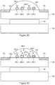
- FIGS. 1A-1Bare perspective views of an array plate and a magnetic device plate in accordance with some embodiments.
- FIGS. 2A-2Gare partial cross-sectional views of a system in accordance with some embodiments.
- FIGS. 2H-2Jare partial cross-sectional views of a system in accordance with some embodiments.
- FIGS. 3A-3Dare plan views of an array plate in accordance with some embodiments.
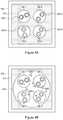
- FIGS. 4A-4Dare plan views of an array plate in accordance with some embodiments.
- FIGS. 4E-4Hare plan views of an array plate in accordance with some embodiments.
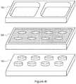
- FIG. 4Iis an exploded view of a system comprising an array plate, a magnetic device plate, and a grid in accordance with some embodiments.
- FIGS. 4J-4Kare plan views of an array plate in accordance with some embodiments.
- FIG. 5is a flow diagram illustrating a method of obtaining target molecules bound to magnetic components in accordance with some embodiments.
- FIG. 6is a flow diagram illustrating a method of detecting target molecules in accordance with some embodiments.
- FIG. 7is a flow diagram illustrating a method of obtaining target molecules bound to magnetic components in accordance with some embodiments.
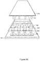
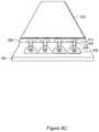
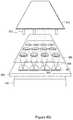
- FIGS. 8A-8Hillustrate a method of transferring magnetic components from a solution in accordance with some embodiments.
- FIGS. 8I-8Lillustrate a method of retrieving supernatants from a solution containing magnetic components in accordance with some embodiments.
- FIGS. 9A-9Bare flow diagrams illustrating a method of retrieving magnetic components from a solution in accordance with some embodiments.
- Methods and devices described hereinallow for more efficient and accurate biological assays.
- magnetic componentse.g., magnetic beads, magnetic particles, etc.
- FIGS. 1A-1Bare perspective views of exemplary array plate 100 and magnetic device plate 140 in accordance with some embodiments.
- Exemplary array plate 100includes an array of sample regions 120 .
- sample regions 120are surrounded by one or more surrounding regions 110 .
- sample regions 120are hydrophilic regions.
- surrounding region 110is a hydrophobic region.
- sample regions 120are hydrophobic regions and surrounding region 110 is a hydrophilic region.
- the hydrophilic and hydrophobic regionsare formed by using different materials (e.g., hydrophilic material for the hydrophilic regions and hydrophobic material for hydrophobic regions).
- the hydrophilic and hydrophobic regionsare formed by chemically or physically treating a surface of array plate 100 .
- array plate 100has a flat continuous surface.
- sample regions 120 and surrounding region 110are formed on the flat continuous surface.
- sample regions 120 and the one or more surrounding regions 110are formed on different surfaces (e.g., sample regions 120 protrude from surrounding region 110 or are indented).
- magnetic device plate 140includes a plurality of magnetic devices 150 (e.g., magnets).
- magnetic devices 150include permanent magnets.
- magnetic devices 150include electromagnets (e.g., an electric coil coupled with a current source, capable of generating a magnetic field).
- magnetic devices 150 in magnetic device plate 140are aligned with sample regions 120 in array plate 100 .
- magnetic device plate 140includes fewer magnetic devices 150 than a number of sample regions 120 in array plate 100 .
- magnetic device plate 140includes one magnetic device 150 .
- FIG. 1Aillustrates that magnetic device plate 140 is positioned at a distance from array plate 100 so that the magnetic field applied by magnetic devices 150 on array plate 100 is reduced (e.g., at least some of the magnetic particles on array plate 100 are not held down by the magnetic force applied by magnetic devices 150 ).
- FIG. 1Billustrates that magnetic device plate 140 is positioned adjacent to array plate 100 so that the magnetic field applied by magnetic devices 150 on sample regions 120 is increased (e.g., at least some of the magnetic particles on array plate 100 are held down by the magnetic force applied by magnetic devices 150 , pulling the magnetic particles toward magnetic devices 150 ).
- magnetic device plate 140when magnetic device plate 140 includes electromagnets, the magnetic field applied by magnetic devices 150 on sample regions 120 is turned on or off by controlling an electrical current provided to the electromagnets.
- FIGS. 2A-2Gare partial cross-sectional views of a system in accordance with some embodiments.
- FIG. 2Aillustrates that sample solution 210 is located on sample region 120 .
- Sample solution 210includes a plurality of magnetic components (e.g., magnetic beads, magnetic particles, etc.) 220 - 1 , 220 - 2 , and 220 - 3 .
- Respective magnetic components 220are configured to couple with respective target molecules 230 (e.g., proteins, nucleic acids, peptides, etc.).
- target molecules 230e.g., proteins, nucleic acids, peptides, etc.
- magnetic components 220are coated with antibodies configured to bind with antigens, or with oligonucleotides configured to capture target nucleic acid molecules.
- magnetic component 220is coated with particular antibodies (e.g., capture antibodies) that are configured to capture particular target molecules 230 .
- magnetic component 220 - 1is coated with antibodies that are configured to capture target molecule 230 - 1
- magnetic component 220 - 2is coated with antibodies that are configured to capture target molecules 230 - 2 . Due to the positioning of magnetic device 150 adjacent to sample region 120 , magnetic components 220 are located close to the surface of sample region 120 (e.g., magnetic components 220 are pulled toward the surface of sample region 120 ).
- magnetic components 220are associated with respective signals (e.g., optical signals). For example, when illuminated with a light source (e.g., light from a light-emitting diode or a laser), magnetic component 220 - 1 emits light of a first wavelength pattern, magnetic component 220 - 2 emits light of a second wavelength pattern that is distinct from the first wavelength pattern, and magnetic component 220 - 3 emits light of a third wavelength pattern that is distinct from the first wavelength pattern and the second wavelength pattern.
- a light sourcee.g., light from a light-emitting diode or a laser
- magnetic component 220 - 1when illuminated with a light source (e.g., light from a light-emitting diode or a laser), magnetic component 220 - 1 emits light of a first wavelength pattern, magnetic component 220 - 2 emits light of a second wavelength pattern that is distinct from the first wavelength pattern, and magnetic component 220 - 3 emits light of a third wavelength pattern that is
- an identity of the respective magnetic componentcan be determined (e.g., whether the respective magnetic component is magnetic component 220 - 1 , magnetic component 220 - 2 , or magnetic component 220 - 3 can be determined).
- magnetic component 220is embedded with material that emits light of a particular wavelength pattern when illuminated with a light source.
- magnetic component 220is coated with material that emits light of a particular wavelength pattern when illuminated with a light source.
- FIG. 2Aalso illustrates that sample solution 210 includes a plurality of target molecules 230 - 1 , 230 - 2 , and 230 - 3 .
- Target molecules 230include analytes whose presence and quantity in sample solution 210 are to be determined.
- sample solution 210By incubating sample solution 210 (e.g., waiting for 2-24 hours), at least some of target molecules 230 bind to magnetic components 220 (or antibodies coating magnetic components 220 ), as shown in FIG. 2B .
- sample solution 210is agitated (e.g., by agitating or shaking array plate 100 ) during the incubation. Agitating sample solution 219 increases the movement of target molecules 230 , which facilitates binding of target molecules 230 with antibodies on magnetic components 220 .
- magnetic components 220should freely float during incubation (e.g., in the absence of any adjacent magnet) to improve binding of target molecules 230 to magnetic components 220 .
- the inventor of this applicationhas made a surprising discovery that placing magnetic device 150 adjacent to sample region 120 , which pulls magnetic components 220 toward a surface of array plate 100 , does not adversely affect binding of target molecules 230 to magnetic components 220 .
- the inventor of this applicationhas made a surprising discovery that placing magnetic device 150 adjacent to sample region 120 reduces challenges associated with incubation in the absence of any adjacent magnet, as described below with respect to FIGS. 2I-2J .
- FIG. 2Balso illustrates that sample solution 210 includes target molecules 230 that are not bound to magnetic components 220 (e.g., due to the absence of magnetic components coated with corresponding capture antibodies, the excess amount of target molecules 230 , the affinity between the antibodies and target molecules 230 , etc.).
- FIG. 2Cillustrates that target molecules 230 that are not bound to magnetic components 220 are removed from sample solution 210 (e.g., by washing, including removing at least a portion of sample solution 210 , and adding a washing solution to sample solution 210 ) and target molecules 230 that are bound to magnetic components 220 remain in sample solution 210 .
- FIG. 2Dillustrates that detection molecules 240 are added to sample solution 210 .
- Detection molecule 240includes a binding portion (e.g., detection antibody) that is configured to couple with target molecule 230 .
- detection molecule 240 - 1is configured to couple with target molecule 230 - 1
- detection molecule 240 - 2is configured to couple with target molecule 230 - 2 .
- detection molecules 240include labels that emit light of particular wavelength patterns when illuminated with a light source.
- detection molecules 240are configured to couple with labels, but do not include labels.
- FIG. 2Eillustrates that at least some of detection molecules 240 bind to target molecules 230 .
- FIG. 2Fillustrates that detection molecules 240 that are bound to target molecules 230 remain in sample solution 210 and detection molecules 240 - 2 that are not bound to target molecules 230 are removed from sample solution 210 (e.g., by washing, including removing at least a portion of sample solution 210 , and adding a washing solution to sample solution 210 , and, optionally repeating the removing and adding steps).
- FIG. 2Gillustrates that magnetic device plate 140 (shown in FIG. 2F ) is moved away from array plate 100 , and magnetic components 220 are released from the surface of array plate 100 .
- magnetic components 220coupled with target molecules 230 , which, in turn, are coupled with detection molecules 240 , float in sample solution 210 .
- a combination of magnetic component 220 , target molecule 230 , and detection molecule 240is detected by optically scanning sample region 210 .
- a combination of light emitted by detection molecule 240 and light emitted by magnetic component 220indicates the presence of target molecule 230 that corresponds to both magnetic component 220 and detection molecule 240 .
- a combination of light emitted by detection molecule 240 - 1 and light emitted by magnetic component 220 - 1indicates presence of target molecule 230 - 1
- a combination of light emitted by detection molecule 240 - 2 and light emitted by magnetic component 220 - 2indicates presence of target molecule 230 - 2 .
- intensity of light emitted by detection molecules 240indicates quantities of corresponding target molecules 230 .
- intensity of light emitted by detection molecule 240 - 1indicates a quantity of target molecule 230 - 1
- intensity of light emitted by detection molecule 240 - 2indicates a quantity of target molecule 230 - 2 .
- a combination of magnetic component 220 , target molecule 230 , and detection molecule 240is detected by using flow cytometry. In some embodiments, by flowing sample solution 210 through a flow cytometer, each combination of magnetic component 220 , target molecule 230 , and detection molecule 240 is separately detected.
- FIG. 2Hillustrates that sample solutions 210 - 1 through 210 - 5 are covered with immiscible fluid 250 (e.g., perfluorocarbon liquid when sample solutions 210 - 1 through 210 - 5 are water-based).
- immiscible fluid 250reduces inter-mixing of sample solutions 210 .
- Nozzle 260e.g., a tip of a pipette or a sipper
- sample solutions 210 - 1 through 210 - 5are sequentially collected (and optionally, separated by immiscible fluid 250 ).
- the collected sample solutions 210 - 1 through 210 - 5can be analyzed (e.g., by flowing the collected sample solutions through a flow cytometer) to determine the presence and quantities of target molecules in sample solutions 210 - 1 through 210 - 5 .
- This methodeliminates the need for exchanging pipette tips for removing samples from each sample solution 210 , and allows rapid aspiration of sample solutions 210 - 1 through 210 - 5 .
- continuous aspiration with nozzle 260is compatible with continuous analysis using flow cytometry, therefore the integration of the sample collection with the flow cytometry analysis improves the throughput of bioassays.
- magnetic device plate 140when eluates are needed for detection (e.g., when magnetic components interfere with detection of analytes), magnetic device plate 140 is placed in proximity to array plate 100 so that magnetic components are retained while eluates are aspirated by nozzle 260 . In some embodiments, when a combination of a target molecule and a magnetic component (and optionally, a detection molecule) is needed for detection, magnetic device plate 140 is removed to release the combination so that the combination is aspirated by nozzle 260 .
- FIGS. 2I-2Jare partial cross-sectional views of a system in accordance with some embodiments.
- FIG. 2Iillustrates that magnetic components 220 are free floating in sample solution 210 along with target molecules 230 .
- FIG. 2Jillustrates that, in some cases, magnetic components 220 aggregate, thereby forming a lump of magnetic components 220 .
- target molecules 230include sticky molecules (e.g., sticky protein)
- the sticky moleculesfacilitate aggregation of magnetic components 220 .
- Aggregation of magnetic components 220reduces accuracy in detecting target molecules 230 .
- formation of an aggregate of magnetic components 220blocks certain binding sites on magnetic components 220 , thereby hindering binding of target molecules 230 with magnetic components 220 .
- formation of an aggregate of magnetic components 220blocks certain binding sites on target molecules 230 , thereby hindering binding of target molecules 230 with detection molecules.
- Magnetic components 220 and/or target molecules 230are trapped in the aggregate of magnetic components 220 reduce specificity in bioassays and increases background signal. Furthermore, an aggregate of magnetic components 220 is unsuitable for, and/or incompatible with, detection of magnetic components in some cases (e.g., certain detection methods require magnetic components 220 to be separated).
- FIGS. 3A-3Dare plan views of an array plate in accordance with some embodiments.
- FIG. 3Aillustrates that sample solution 310 is located on a sample region of array plate 100 .
- Sample solution 310includes a plurality of magnetic components 320 (e.g., 320 - 1 , 320 - 2 , and 320 - 3 ) configured to couple with respective target molecules 330 .
- Sample solution 310also includes target molecules 330 (e.g., 330 - 1 and 330 - 2 ) and detection molecules 340 (e.g., 340 - 1 and 340 - 2 ).
- target molecule 330 - 1is coupled with magnetic component 320 - 1 and detection molecule 340 - 1
- target molecule 330 - 2is coupled with magnetic component 320 - 2 and detection molecule 340 - 2 .
- FIG. 3Billustrates that target molecule 330 - 1 is released from magnetic component 320 - 1 and target molecule 330 - 2 is released from magnetic component 320 - 2 .
- target molecules 330 - 1 and 330 - 2are released from magnetic components 320 - 1 and 320 - 2 in response to adding an elution buffer to sample solution 310 .
- Certain detection methodsrequire target molecules 330 (optionally coupled with detection molecules 340 ) without magnetic components 320 .
- separating target molecules 330 from magnetic components 320requires aspirating at least a portion of sample solution 310 that includes at least a subset of target molecules 330 while magnetic components 320 are retained by one or more magnetic devices.
- such methodsare time-consuming and inefficient.
- certain target molecules 330are lost during aspiration of sample solution 310 . Contamination of sample solution 310 is also possible.
- transferring sample solution 310requires use of disposable pipette tips, which adds to costs of bioassays and increased wastes.
- FIG. 3Cshows that by placing magnetic device 350 (e.g., a permanent magnet) adjacent to sample solution 310 and passing magnetic device 350 by sample solution 310 (e.g., under sample solution 310 ) separates magnetic components 320 from target molecules 330 .
- magnetic components 320are located along one edge of sample solution 310 that is adjacent to magnetic device 350 .
- FIG. 3Dshows that if magnetic device 350 provides a sufficient magnetic force (e.g., sufficient to overcome surface tension), magnetic components 320 are separated from sample solution 310 .
- sample solution 310is agitated (e.g., shaken) while magnetic device 350 passes by sample solution 310 to facilitate the movement of magnetic components 320 .
- a second set of magnetic componentse.g., magnetic components different from those separated from sample solution 310
- processinge.g., separation of a subset of target molecules.
- processinge.g., disassociation and targeted retention
- FIGS. 3C-3Dillustrate methods of spatially separating magnetic components 320 from target molecules 330 within a same sample solution. Such methods overcome limitations associated with conventional methods.
- FIGS. 4A-4Dare plan views of array plate 100 in accordance with some embodiments.
- FIG. 4Aillustrates that array plate 100 has multiple sample regions 120 (e.g., 120 - 1 through 120 - 4 ).
- magnetic components 420 - 1are located over sample region 120 - 1
- magnetic components 420 - 2are located over sample region 120 - 2
- magnetic components 420 - 3are located over sample region 120 - 3
- magnetic components 420 - 4are located over sample region 120 - 4 .
- a solution that contains magnetic components 420 - 1is dispensed over sample region 420 - 1 .
- FIG. 4Aillustrates that array plate 100 has multiple sample regions 120 (e.g., 120 - 1 through 120 - 4 ).
- magnetic components 420 - 1are located over sample region 120 - 1
- magnetic components 420 - 2are located over sample region 120 - 2
- magnetic components 420 - 3are located over sample region 120 - 3
- magnetic components 420 - 4are located over sample region 120 - 4 .
- the volume of the solution that contains magnetic components 420 - 1is such that the solution does not come into contact with another sample region (e.g., 120 - 2 or 120 - 3 ).
- another sample regione.g., 120 - 2 or 120 - 3 .
- a solution volume between 1 ⁇ l and 3 ⁇ lmay be used to deliver magnetic components.
- each sample regionhas a diameter of 0.5 mm, 1 mm, 2 mm, 3 mm, 4 mm, 5 mm, 6 mm, 7 mm, 8 mm, 9 mm, 10 mm, 11 mm, 12 mm, 13 mm, 14 mm, 15 mm, 16 mm, 17 mm, 18 mm, 19 mm, 20 mm, 21 mm, 22 mm, 23 mm, 24 mm, 25 mm, or 26 mm.
- sample regions within a same groupare spaced apart. For example, sample regions having a diameter of 2 mm in a same group are spaced apart with 3 mm, 4 mm, or 5 mm pitch.
- a magnetic device plate(e.g., magnetic device plate 140 shown in FIG. 1A ) is placed adjacent to array plate 100 to retain magnetic components 420 .
- the magnetic device plateremains adjacent to array plate 100 until magnetic components 420 need to be removed (e.g., for flow cytometry analysis).
- the magnetic device plateremains adjacent to array plate 100 throughout operations illustrated in FIGS. 4A-4D and FIGS. 4E-4H .
- FIG. 4Billustrates that sample solution 410 is dispensed so that sample solution 410 comes in contact with sample regions 120 - 1 , 120 - 2 , 120 - 3 , and 120 - 4 .
- the volume of sample solution 410is sufficient to contact sample regions 120 - 1 , 120 - 2 , 120 - 3 , and 120 - 4 .
- Sample solution 410includes target molecules 430 . Surrounding region 110 reduces spreading of sample solution 410 (e.g., due to its hydrophobicity).
- FIG. 4Cillustrates that at least some target molecules 430 couple with magnetic components 420 .
- target molecule 430 - 1couples with magnetic component 420 - 3
- target molecule 430 - 2couples with magnetic component 420 - 2 , in FIG. 4C .
- FIG. 4Dillustrates that sample solution 410 is removed (e.g., through washing).
- Target molecules 430 that are bound with magnetic components 420remain on array plate 100 , and target molecules 430 that are not bound with magnetic components 420 are removed.
- Target molecules 430 that are bound with magnetic components 420are detected.
- detection moleculese.g., detection molecules 240 in FIG. 2D
- target molecules 430are used to detect target molecules 430 bound with magnetic components 420 .
- target molecules 430are detected by optically scanning array plate 100 .
- target molecules 430are detected by suspending target molecules 430 bound with magnetic components 420 by adding a buffer solution to respective sample regions 120 and analyzing the buffer solution with flow cytometry.
- An array plate that includes hydrophilic regions and hydrophobic regionsallows bioassays with a small sample volume (e.g., 5 ⁇ l or less). However, it is difficult to detect low concentration analytes in a small sample volume, when an average number of analytes in the sample volume approaches one or less.
- a droplet placed on sample region 120 - 1may not include target molecules that can be detected by magnetic components on sample region 120 - 1 (or may not include sufficient target molecules that can be detected by magnetic components on sample region 120 - 1 ), whereas a droplet placed on sample region 120 - 2 may include target molecules that can be detected by magnetic components on sample region 120 - 1 (or may include sufficient target molecules that can be detected by magnetic components on sample region 120 - 1 ).
- respective target molecules in sample solution 410may move to sample regions 120 - 1 , 120 - 2 , 120 - 3 , and 120 - 4 and bind with respective magnetic components configured to couple with the respective target molecules.
- FIGS. 4A-4Dovercome this challenge.
- FIGS. 4E-4Hare plan views of an array plate in accordance with some embodiments.
- sample region 120 - 1includes magnetic component 420 - 1 configured to couple with a target molecule of a first type (e.g., target molecule 430 - 1 in FIG. 4E ) and magnetic component 420 - 5 configured to couple with a target molecule of a fifth type.
- magnetic component 420 - 1 and magnetic component 420 - 5are placed on sample region 120 - 1 in a droplet that does not initially contact other sample regions (e.g., sample region 120 - 2 , 120 - 3 , and 120 - 4 ).
- Sample region 120 - 2includes magnetic component 420 - 2 configured to couple with a target molecule of a second type (e.g., target molecule 430 - 2 in FIG. 4F ) and magnetic component 420 - 6 configured to couple with a target molecule of a sixth type (e.g., target molecule 430 - 4 in FIG. 4F ).
- Sample region 120 - 3includes magnetic component 420 - 3 configured to couple with a target molecule of a third type and magnetic component 420 - 7 configured to couple with a target molecule of a seventh type.
- Sample region 120 - 4includes magnetic component 420 - 4 configured to couple with a target molecule of a fourth type and magnetic component 420 - 8 configured to couple with a target molecule of an eighth type.
- FIG. 4Eillustrates that magnetic components 420 - 1 , 420 - 2 , 420 - 3 , and 420 - 4 are associated with a first signal and magnetic components 420 - 5 , 420 - 6 , 420 - 7 , and 420 - 8 are associated with a second signal that is distinct from the first signal.
- magnetic components 420 - 1 , 420 - 2 , 420 - 3 , and 420 - 4emit light of a first wavelength pattern when illuminated by a light source
- magnetic components 420 - 5 , 420 - 6 , 420 - 7 , and 420 - 8emit light of a second wavelength pattern when illuminated by the light source.
- magnetic components 420 - 1 , 420 - 2 , 420 - 3 , and 420 - 4can be distinguished from magnetic components 420 - 5 , 420 - 6 , 420 - 7 , and 420 - 8 based on the wavelength pattern in the emitted light.
- FIG. 4Fillustrates that sample solution 410 is dispensed so that sample solution 410 comes in contact with sample regions 120 - 1 , 120 - 2 , 120 - 3 , and 120 - 4 .
- the volume of sample solution 410is sufficient to contact sample regions 120 - 1 , 120 - 2 , 120 - 3 , and 120 - 4 .
- Sample solution 410includes target molecules 430 . Surrounding region 110 reduces spreading of sample solution 410 (e.g., due to its hydrophobicity).
- FIG. 4Gillustrates that at least some target molecules 430 couple with magnetic components 420 .
- target molecule 430 - 1couples with magnetic component 420 - 3
- target molecule 430 - 2couples with magnetic component 420 - 2
- target molecule 430 - 4couples with magnetic component 420 - 6 , in FIG. 4G .
- FIG. 4Hillustrates that sample solution 410 is removed (e.g., through washing).
- Target molecules 430 that are bound with magnetic components 420remain on array plate 100 , and target molecules 430 that are not bound with magnetic components 420 are removed.
- Target molecules 430 that are bound with magnetic components 420are detected.
- detection moleculese.g., detection molecules 240 in FIG. 2D
- target molecules 430are detected by optically scanning array plate 100 .
- target molecules 430are detected by suspending target molecules 430 bound with magnetic components 420 by adding a buffer solution to respective sample regions 120 and analyzing the buffer solution with flow cytometry.
- FIG. 4Iis an exploded view of a system comprising array plate 100 , magnetic device plate 140 , and grid 160 in accordance with some embodiments.
- array plate 100includes a thin layer of immiscible liquid (e.g., perfluorocarbon liquid) is applied.
- immiscible liquide.g., perfluorocarbon liquid
- the layer of immiscible liquidimproves a seal between grid 160 and array plate 100 .
- the combination of grid 160 and array plate 100allows a larger volume of a sample solution to be placed on sample regions without spreading the sample solution.
- FIGS. 4J-4Kare plan views of an array plate in accordance with some embodiments.
- FIG. 4Jillustrates that sample regions 120 - 1 , 120 - 2 , 120 - 3 , and 120 - 4 are configured to couple with target molecules.
- sample regions 120 - 1 , 120 - 2 , 120 - 3 , and 120 - 4are coated with capture molecules (e.g., antibodies, nucleic acid probes, etc.) for capturing (or coupling with) target molecules.
- capture moleculese.g., antibodies, nucleic acid probes, etc.
- FIG. 4Killustrates that sample regions 120 - 1 , 120 - 2 , 120 - 3 , and 120 - 4 are each coated with two different types of capture molecules.
- sample region 120 - 1includes capture molecules configured to couple with a target molecule of a first type and capture molecules configured to couple with a target molecule of a fifth type.
- Sample region 120 - 2includes capture molecules configured to couple with a target molecule of a second type and capture molecules configured to couple with a target molecule of a sixth type.
- Sample region 120 - 3includes capture molecules configured to couple with a target molecule of a third type and capture molecules configured to couple with a target molecule of a seventh type.
- Sample region 120 - 4includes capture molecules configured to couple with a target molecule of a fourth type and capture molecules configured to couple with a target molecule of an eighth type.
- target molecules captured in a sample regionare eluted and subsequently analyzed (e.g., using magnetic components and/or detection molecules).
- FIGS. 4A-4Killustrate the use of a group of four sample regions
- a person having ordinary skill in the artwould understand that more or fewer sample regions may be used as a group.
- a group of two sample regions, a group of nine sample regions (3 ⁇ 3), or a group of sixteen sample regions (4 ⁇ 4)may be used.
- all of the sample regions on an array plateis used as a single group.
- two groupsare spaced apart by 9 mm or 10 mm (e.g., center-to-center).
- FIG. 5is a flow diagram illustrating method 500 of obtaining target molecules bound to magnetic components in accordance with some embodiments.
- Method 500includes ( 502 ) obtaining an array plate with a sample surface that includes a plurality of sample regions and a surrounding region (e.g., array plate 100 in FIG. 1A ).
- the plurality of sample regionshas a first surface tension (e.g., the sample regions are hydrophilic).
- the surrounding regionhas a second surface tension.
- the second surface tensionis distinct from the first surface tension (e.g., the surrounding region is hydrophobic).
- the first surface tension and the second surface tensionare the same.
- a sample solutionis located on a sample region of the plurality of sample regions (e.g., sample solution 210 in FIG. 2A ).
- the sample solutionincludes a plurality of target molecules (e.g., target molecules 230 in FIG. 2A ).
- the sample solutionincludes a plurality of magnetic components (e.g., magnetic components 220 in FIG. 2A , such as magnetic beads, magnetic particles, etc.), respective magnetic components of the plurality of magnetic components configured to couple with respective target molecules
- the respective magnetic componentshave ( 504 ) respective signatures (e.g., optical signatures, such as fluorescence signals, absorption signals, Raman signals, etc.; electrical signatures, such as impedance, resistance, capacitance, etc.; magnetic signatures; etc.).
- respective signaturese.g., optical signatures, such as fluorescence signals, absorption signals, Raman signals, etc.
- electrical signaturessuch as impedance, resistance, capacitance, etc.
- magnetic signaturesetc.
- Method 500also includes ( 506 ) incubating the sample solution while one or more magnetic devices are positioned adjacent to the sample solution (e.g., FIG. 2B ).
- method 500includes ( 508 ) agitating the sample solution while incubating the sample solution. For example, the sample solution is vortexed every 5 minutes while incubating the sample solution.
- method 500includes ( 509 ) incubating the sample solution without agitating the sample solution.
- the sample solutionis first agitated (e.g., vortexed), and subsequently incubated without further agitation (e.g., the sample solution is left stationary without further vortexing).
- method 500includes placing a lid over the array plate while the sample solution is incubated. This reduces evaporation of the sample solution during the incubation.
- Method 500further includes ( 510 ) washing the plurality of magnetic components to obtain target molecules bound to at least a subset of the plurality of magnetic components (e.g., FIG. 2C ).
- method 500includes ( 512 ) detecting the target molecules bound to at least the subset of the plurality of magnetic components.
- the target moleculescan be optically scanned on array plate 100 or extracted for flow cytometry analysis, with or without using detection molecules.
- method 500includes ( 514 ) adding to the sample solution a plurality of detection molecules configured to couple with the respective target molecules (e.g., detection molecules 240 in FIG. 2D ).
- method 500includes ( 516 ) washing the plurality of magnetic components to obtain target molecules bound to at least a subset of the plurality of magnetic components and at least a subset of the plurality of detection molecules (e.g., FIG. 2F ).
- method 500includes ( 518 ) detecting a combination of a respective target molecule coupled with a respective magnetic component and a respective detection molecule.
- the target moleculescan be optically scanned on array plate 100 or extracted for flow cytometry analysis.
- sample regions, sample solutions, magnetic components, and target molecules, described above with reference to method 500optionally have one or more of the characteristics of the sample regions, sample solutions, magnetic components, and target molecules described herein with reference to other methods described herein (e.g., methods 600 , 700 , and 900 ). For brevity, these details are not repeated here.
- FIG. 6is a flow diagram illustrating method 600 of detecting target molecules in accordance with some embodiments.
- Method 600includes ( 602 ) obtaining an array plate with a sample surface that includes a plurality of sample regions and a surrounding region (e.g., array plate 100 in FIG. 3B with a sample region surrounded by surrounding region 110 ).
- the plurality of sample regionshas a first surface tension (e.g., hydrophilic).
- the surrounding regionhas a second surface tension.
- the second surface tensionis distinct from the first surface tension (e.g., the surrounding region is hydrophobic).
- the first surface tension and the second surface tensionare the same.
- a sample solutionis located on a sample region of the plurality of sample regions (e.g., sample solution 310 in FIG. 3B ).
- the sample solutionincludes a plurality of magnetic components configured to couple with respective target molecules (e.g., magnetic components 320 in FIG. 3B ).
- the sample solutionincludes a plurality of target molecules, at least a subset of the target molecules coupled with respective detection molecules and separated from the plurality of magnetic components (e.g., target molecules 330 and magnetic components 320 in FIG. 3B ).
- Method 600also includes ( 604 ) positioning one or more magnetic devices adjacent to the sample solution, and, subsequent to positioning one or more magnetic devices adjacent to the sample solution, ( 606 ) moving the one or more magnetic devices and/or the array plate so that the plurality of magnetic components are spatially separated from at least the subset of the target molecules coupled with the respective detection molecules (e.g., FIG. 3C or FIG. 3D ).
- Method 600further includes ( 608 ) detecting the respective detection molecules in the sample solution.
- sample regions, sample solutions, magnetic components, and target molecules, described above with reference to method 600optionally have one or more of the characteristics of the sample regions, sample solutions, magnetic components, and target molecules described herein with reference to other methods described herein (e.g., methods 500 , 700 , and 900 ). For brevity, these details are not repeated here.
- FIG. 7is a flow diagram illustrating method 700 of obtaining target molecules bound to magnetic components in accordance with some embodiments.
- Method 700includes ( 702 ) obtaining an array plate with a sample surface that includes a plurality of sample regions and a surrounding region (e.g., array plate 100 in FIG. 4E ).
- the plurality of sample regionshas a first surface tension.
- the surrounding regionhas a second surface tension.
- the second surface tensionis distinct from the first surface tension.
- the first surface tension and the second surface tensionare the same.
- a first sample region of the plurality of sample regionshas a first set of magnetic components each configured to couple with a target molecule of a first type (e.g., in FIG. 4E , sample region 120 - 2 has magnetic component 420 - 3 that is configured to couple with target molecule 430 - 2 ).
- a second sample region of the plurality of sample regionshas a second set of magnetic components each configured to couple with a target molecule of a second type that is distinct from a target molecule of the first type (e.g., sample region 120 - 3 has magnetic component 420 - 3 that is configured to couple with target molecule 430 - 1 ).
- the first sample region of the plurality of sample regionshas ( 704 ) a third set of magnetic components each configured to couple with a target molecule of a third type that is distinct from a target molecule of the first type and a target molecule of the second type (e.g., in FIG.
- sample region 120 - 2has magnetic component 420 - 6 that is configured to couple with target molecule 430 - 4 that is distinct from target molecule 430 - 1 and target molecule 430 - 2 ); and the second sample region of the plurality of sample regions has a fourth set of magnetic components each configured to couple with a target molecule of a fourth type that is distinct from a target molecule of the first type, a target molecule of the second type, and a target molecule of the third type (e.g., sample region 120 - 3 has magnetic component 420 - 7 that is configured to couple with a target mole that is distinct from target molecule 430 - 1 , target molecule 430 - 2 , and target molecule 430 - 4 ).
- the first set of magnetic componentsis associated ( 706 ) with a first signal; the second set of magnetic components is associated with a second signal that is distinct from the first signal; the third set of magnetic components is associated with a third signal; and the fourth set of magnetic components is associated with a fourth signal that is distinct from the third signal.
- magnetic bead 420 - 2 and magnetic bead 420 - 6emit different wavelength patterns when illuminated with a light source
- magnetic bead 420 - 3 and magnetic 420 - 7emit different wavelength patterns when illuminated with the light source.
- the third signalis identical ( 708 ) to either the first signal or the second signal.
- magnetic bead 420 - 3 and magnetic bead 420 - 3emit the same wavelength pattern when illuminated with the light source.
- magnetic components 420 - 2 and magnetic components 420 - 3emit a first wavelength pattern when illuminated with a light source
- magnetic components 420 - 6 and magnetic components 420 - 7emit a second wavelength pattern when illuminated with the light source
- magnetic components 420 - 2 and magnetic components 420 - 3have the same color
- magnetic components 420 - 6 and magnetic components 420 - 7have the same color that is distinct from the color of magnetic components 420 - 2 and magnetic components 420 - 3 ).
- Method 700includes ( 710 ) positioning one or more magnetic devices adjacent to the first sample region and the second sample region to retain the magnetic components on the first sample region and the second sample region (e.g., FIG. 1B ).
- Method 700includes ( 712 ) providing a sample solution over multiple sample regions, including the first sample region and the second sample region, of the plurality of sample regions so that a single contiguous volume of the sample solution is in contact with the multiple sample regions, including the first sample region and the second sample region, while the magnetic components on the first sample region and the second sample region are retained by the one or more magnetic devices (e.g., sample solution 410 in FIG. 4F ).
- the one or more magnetic devicese.g., sample solution 410 in FIG. 4F .
- Method 700includes ( 714 ) incubating the sample solution while one or more magnetic devices are positioned adjacent to the first sample region and the second sample region (e.g., some of target molecules 430 bind to at least a subset of magnetic components 420 in FIG. 4G ).
- Method 700includes ( 716 ) washing the magnetic components to obtain target molecules bound to at least a subset of the magnetic components on the first sample region and/or the second sample region (e.g., FIG. 4H ).
- the target molecules bound to magnetic componentsare analyzed to detect the presence and/or quantities of the target molecules (e.g., through optical scanning and/or flow cytometry), with or without detection molecules.
- sample regions, sample solutions, magnetic components, and target molecules, described above with reference to method 700optionally have one or more of the characteristics of the sample regions, sample solutions, magnetic components, and target molecules described herein with reference to other methods described herein (e.g., methods 500 , 600 , and 900 ). For brevity, these details are not repeated here.
- FIGS. 8A-8Hillustrate a method of transferring magnetic components from a solution in accordance with some embodiments.
- FIG. 8Aillustrates array plate 100 that includes a plurality of sample regions 120 and surrounding region 110 .
- the plurality of sample regions 120has a first surface tension (e.g., sample region 120 is hydrophilic); and surrounding region 110 has a second surface tension that is distinct from the first surface tension (e.g., surrounding region 110 is hydrophobic).
- first solution 802(e.g., a sample solution) is located on sample region 120 .
- First solution 802includes a plurality of magnetic components 804 .
- the first solutionincludes a plurality of target molecules; and respective magnetic components of the plurality of magnetic components are configured to couple with respective target molecules.
- the respective magnetic componentsare coupled with respective target molecules (e.g., see FIG. 2C ).
- the first solutionincludes a plurality of detection molecules, and respective detection molecules are coupled with target molecules (e.g., see FIG. 2F ).
- FIG. 8Billustrates that separation layer 806 (e.g., a polymerase chain reaction (PCR) plate, such as a non-skirted (or skirtless) PCR plate) is placed over array plate 100 .
- Separation layer 806includes one or more protrusions 808 (e.g., indentations defining wells).
- protrusion 808is in contact with first solution 802 (e.g., at least a portion of protrusion 808 is immersed in first solution 802 ).
- FIG. 8Balso illustrates magnetic pin array 810 with a plurality of magnetic pins 812 .
- FIG. 8Cillustrates that magnetic pin array 810 is moved so that magnetic pin 812 is placed within protrusion 808 .
- Magnetic pin 812attracts magnetic components 804 in first solution 802 , and magnetic components 804 are placed on a wall of protrusion 808 .
- FIG. 8Dillustrates that separation layer 806 and magnetic pin array 810 are separated from first solution 802 (e.g., separation layer 806 and magnetic pin array 810 are moved away from first solution 802 ; and/or array plate 100 is moved away from separation layer 806 and magnetic pin array 810 ) so that protrusion 808 is no longer in contact with first solution 802 on sample region 120 . Magnetic components 804 remain on the wall of protrusion 808 .
- FIG. 8Eillustrates that separation layer 806 and magnetic pin array 810 are positioned over second array plate 820 .
- Second solution 822e.g., an elution buffer
- Second solution 822is placed on a sample region of second array plate 820 .
- FIG. 8Ealso illustrates magnetic device plate 140 with magnetic devices 150 .
- FIG. 8Fillustrates that separation layer 806 and magnetic pin array 810 are placed adjacent to second array plate 820 so that magnetic components 840 on the wall of protrusion 808 are immersed in second solution 822 .
- FIG. 8Falso illustrates that magnetic device plate 140 is placed adjacent to second array plate 820 (e.g., magnetic device plate 140 is placed underneath second array plate 820 ).
- FIG. 8Gillustrates that magnetic pin array 810 is separated from separation layer 806 (e.g., magnetic pin array 810 is moved away from separation layer 806 and/or separation layer 806 is moved away from magnetic pin array 810 ). As a result, magnetic pin 812 is also separated from protrusion 808 of separation layer 806 .
- FIG. 8Galso illustrates that magnetic components 804 are released from protrusion 808 into second solution 822 .
- second solution 822includes an elution buffer
- target molecules coupled with magnetic components 804are eluted over time (e.g., during incubation for 10 minutes).
- FIG. 8Hillustrates that separation layer 806 is separated from second solution 822 (e.g., separation layer 806 is moved away from second solution 822 , and/or second array plate 820 is moved away from separation layer 806 ).
- FIG. 8Halso illustrates that magnetic device plate 140 is separated from second array plate 820 (e.g., magnetic device plate 140 is moved away from second array plate 820 and/or second array plate 820 is moved away from magnetic device plate 140 ).
- magnetic device plate 140is separated from second array plate 820 after separation layer 806 is separated from second solution 822 .
- magnetic device plate 140is separated from second array plate 820 before separation layer 806 is separated from second solution 822 .
- magnetic device plate 140is separated from second array plate 820 concurrently with the separation of separation layer 806 from second solution 822 .
- FIGS. 8I-8Lillustrate a method of retrieving supernatants from a solution containing magnetic components (e.g., magnetic beads) in accordance with some embodiments.
- magnetic componentse.g., magnetic beads
- FIG. 8Iillustrates magnetic device plate 830 .
- Magnetic device plate 830includes a plurality of linear magnetic devices 832 .
- Linear magnetic devices 832are positioned on magnetic device plate 320 in such a way that, when the magnetic device plate 830 is positioned adjacent to second array plate 820 , magnetic devices 832 are positioned offset sample regions.
- magnetic components 804are aggregated and positioned offset from a center of a sample region with second solution 822 , as shown in FIG. 8J .
- FIG. 8Killustrates that a portion of second solution 822 is aspirated (e.g., by using a pipette 850 ). As illustrated in FIG. 8K , a portion of second solution 822 is aspirated from a location that is away from the location of magnetic components 804 . In some embodiments, the aspirated solution is analyzed. This separation of magnetic components 804 and eluted target molecules improves accuracy in determining the quantity of target molecules in second solution 822 and/or reduces malfunction of an analysis instrument configured for detecting the presence of, or analyzing the quantity of, target molecules in second solution 822 .
- FIG. 8Lillustrates that magnetic device plate 840 that includes a two-dimensional array of magnetic devices 842 is used instead of magnetic device plate 830 .
- magnetic devices 842are magnetic pins (e.g., magnetic devices that have an elongated shape and are positioned substantially orthogonal to a surface of magnetic device plate 840 ). In some cases, magnetics with a smaller cross-section have been found to be more effective in attracting magnetic components 804 .
- FIGS. 8A-8Lare described with respect to a single sample region, as illustrated in FIG. 8A-8L , analogous operations can be performed concurrently with respect to multiple sample regions on sample arrays 100 and 820 .
- magnetic componentscan be retrieved from a plurality of solutions in parallel, thereby increasing the speed of retrieving the magnetic components.
- magnetic componentscan be transferred to a plurality of solutions in parallel, thereby increasing the speed of transferring the magnetic components.
- FIGS. 9A-9Bare flow diagrams illustrating method 900 of retrieving magnetic components from a solution in accordance with some embodiments.
- Method 900includes ( 902 ) obtaining an array plate with a sample surface that includes a plurality of sample regions and a surrounding region (e.g., FIG. 8A ).
- a first solutionis located on a sample region of the plurality of sample regions.
- the first solutionincludes a plurality of magnetic components.
- the first solutionincludes ( 904 ) a plurality of target molecules; and respective magnetic components of the plurality of magnetic components are configured to couple with respective target molecules (e.g., FIG. 2F ).
- the plurality of sample regionshas ( 906 ) a first surface tension; and the surrounding region has a second surface tension that is distinct from the first surface tension.
- Method 900includes ( 908 ) placing a separation layer that includes one or more protrusions so that at least a respective protrusion of the one or more protrusions is at least partially immersed in the first solution (e.g., FIG. 8B ).
- method 900includes ( 910 ), prior to placing the separation layer: incubating the first solution; and washing the plurality of magnetic components to obtain target molecules bound to at least a subset of the plurality of magnetic components (e.g., unbound target molecules and/or detection molecules are removed, as shown in FIG. 2F ). For example, operations illustrated in FIG. 2A-2F are performed to obtain target molecules bound to at least a subset of the plurality of magnetic components. In some embodiments, detection molecules bound to the target molecules are also obtained.
- method 900includes ( 912 ) incubating the first solution while one or more magnetic devices are positioned adjacent to the first solution, underneath the first solution (e.g., magnetic device plate 140 shown in FIG. 2D ).
- method 900includes ( 914 ) washing the plurality of magnetic components while one or more magnetic devices are positioned adjacent to the first solution, underneath the first solution (e.g., magnetic device plate 140 shown in FIG. 2F ).
- Method 900includes ( 916 ) placing a first magnetic device within the respective protrusion (e.g., FIG. 8C ).
- Method 900includes retrieving ( 918 , FIG. 9B ) at least a portion of the plurality of magnetic components from the first solution by separating the separation layer and the magnetic device from the first solution so that the respective protrusion ceases to be at least partially immersed in the first solution on the sample region (e.g., FIG. 8D ).
- method 900includes ( 920 ) obtaining a second array plate with a second sample surface that includes a second plurality of sample regions and a second surrounding region (e.g., FIG. 8E ).
- a second solutionis located on a sample region of the second plurality of sample regions.
- Method 900also includes placing the separation layer and the first magnetic device adjacent to the second solution so that the retrieved portion of the plurality of magnetic components and at least a portion of the respective protrusion are immersed in the second solution (e.g., FIG. 8F ); while a second magnetic device is placed adjacent to the second solution, moving the first magnetic device away from the separation layer (e.g., FIG.
- the second plurality of sample regionshas a third surface tension (e.g., the second plurality of samples regions is hydrophilic) and the second surrounding region has a fourth surface tension that is distinct from the third surface tension (e.g., the second surrounding region is hydrophobic).
- the third surface tensionis identical to the first surface tension.
- the fourth surface tensionis identical to the second surface tension.
- method 900includes ( 922 ) positioning the second magnetic device to move the retrieved portion of the plurality of magnetic components to a first location within the second solution (e.g., FIG. 8J ); and aspirating at least a portion of the second solution from a location within the second solution that is distinct from the first location (e.g., FIG. 8K ).
- method 900includes ( 924 ) positioning a third magnetic device, that is distinct from the second magnetic device, to move the retrieved portion of the plurality of magnetic components to a first location within the second solution (e.g., FIG. 8L ); and aspirating at least a portion of the second solution from a location within the second solution that is distinct from the first location (e.g., FIG. 8L ).
- method 900includes ( 926 ), prior to positioning the magnetic device, agitating the second solution. This initiates movement of the magnetic components within the second solution, which facilitates movement of the magnetic components toward the magnetic device (e.g., the second magnetic device or the third magnetic device).
- the magnetic devicee.g., the second magnetic device or the third magnetic device.
- method 900includes ( 928 ) analyzing the aspirated solution. For example, if the aspirated solution includes detection antibodies, labels (e.g., fluorescence molecules) on the detection antibodies are detected by a plate reader (e.g., an enzyme-linked immunosorbent assay (ELISA) plate reader).
- a plate readere.g., an enzyme-linked immunosorbent assay (ELISA) plate reader.
- the first magnetic deviceis placed within the respective protrusion of the separation layer prior to placing the separation layer so that the respective protrusion is at least partially immersed in the first solution.
- the separation layeris placed so that the respective protrusion is at least partially immersed in the first solution, prior to placing the first magnet within the respective protrusion.
- one or more operations described hereinmay be omitted.
- details of other processes described herein with respect to other methods described hereine.g., methods 500 , 600 , and 700
- the sample regions, sample solutions, magnetic components, and target molecules, described above with reference to method 900optionally have one or more of the characteristics of the sample regions, sample solutions, magnetic components, and target molecules described herein with reference to other methods described herein (e.g., methods 500 , 600 , and 700 ).
- the methods for performing assays as illustrated in FIGS. 2A-2G, 3A-3D, and 4A-4Kcan be combined with the method for retrieving and transferring magnetic components illustrated in FIGS. 8A-8L . For brevity, many of these details are not repeated here.
- array platescan be used in various biological and chemical reactions. Therefore, such details and specific examples are omitted for brevity.
Landscapes
- Health & Medical Sciences (AREA)
- Immunology (AREA)
- Life Sciences & Earth Sciences (AREA)
- Engineering & Computer Science (AREA)
- Chemical & Material Sciences (AREA)
- Molecular Biology (AREA)
- Biomedical Technology (AREA)
- Hematology (AREA)
- Urology & Nephrology (AREA)
- Biotechnology (AREA)
- Biochemistry (AREA)
- Cell Biology (AREA)
- Food Science & Technology (AREA)
- Medicinal Chemistry (AREA)
- Physics & Mathematics (AREA)
- Analytical Chemistry (AREA)
- Microbiology (AREA)
- General Health & Medical Sciences (AREA)
- General Physics & Mathematics (AREA)
- Pathology (AREA)
- Chemical Kinetics & Catalysis (AREA)
- Apparatus Associated With Microorganisms And Enzymes (AREA)
- Automatic Analysis And Handling Materials Therefor (AREA)
Abstract
Description
Claims (11)
Priority Applications (1)
| Application Number | Priority Date | Filing Date | Title |
|---|---|---|---|
| US15/184,846US10545139B2 (en) | 2015-06-16 | 2016-06-16 | Methods and devices for performing biological assays using magnetic components |
Applications Claiming Priority (3)
| Application Number | Priority Date | Filing Date | Title |
|---|---|---|---|
| US201562180259P | 2015-06-16 | 2015-06-16 | |
| US201662292689P | 2016-02-08 | 2016-02-08 | |
| US15/184,846US10545139B2 (en) | 2015-06-16 | 2016-06-16 | Methods and devices for performing biological assays using magnetic components |
Publications (2)
| Publication Number | Publication Date |
|---|---|
| US20170038372A1 US20170038372A1 (en) | 2017-02-09 |
| US10545139B2true US10545139B2 (en) | 2020-01-28 |
Family
ID=58052955
Family Applications (1)
| Application Number | Title | Priority Date | Filing Date |
|---|---|---|---|
| US15/184,846Active2037-07-08US10545139B2 (en) | 2015-06-16 | 2016-06-16 | Methods and devices for performing biological assays using magnetic components |
Country Status (1)
| Country | Link |
|---|---|
| US (1) | US10545139B2 (en) |
Citations (113)
| Publication number | Priority date | Publication date | Assignee | Title |
|---|---|---|---|---|
| US3426108A (en) | 1965-05-28 | 1969-02-04 | Ilikon Corp | Method of fabricating shell type polystyrene articles |
| GB1291610A (en) | 1969-01-08 | 1972-10-04 | Nuclear Chicago Corp | Automatic liquid scintillation counting system |
| US3754872A (en) | 1971-03-18 | 1973-08-28 | Siemens Ag | Test tube for body liquids |
| US5041266A (en) | 1989-12-21 | 1991-08-20 | Hoffmann-La Roche Inc. | Tray for immunometric determinations |
| US5219528A (en) | 1989-07-28 | 1993-06-15 | Pierce Chemical Company | Apparatus for rapid immunoassays |
| US5229163A (en) | 1989-12-21 | 1993-07-20 | Hoffmann-La Roche Inc. | Process for preparing a microtiter tray for immunometric determinations |
| US5506121A (en) | 1992-11-03 | 1996-04-09 | Institut Fur Bioanalytik Gemeinnutzige Gesellschaft MBH | Fusion peptides with binding activity for streptavidin |
| WO1996023879A1 (en) | 1995-01-30 | 1996-08-08 | Terrapin Technologies, Inc. | Glubodies - multiplicities of proteins capable of binding a variety of small molecules |
| US5560811A (en) | 1995-03-21 | 1996-10-01 | Seurat Analytical Systems Incorporated | Capillary electrophoresis apparatus and method |
| US5567326A (en)* | 1994-09-19 | 1996-10-22 | Promega Corporation | Multisample magnetic separation device |
| US5691147A (en) | 1994-06-02 | 1997-11-25 | Mitotix, Inc. | CDK4 binding assay |
| EP0812693A1 (en) | 1995-12-25 | 1997-12-17 | Seiko Epson Corporation | Ink-jet recording apparatus for ink cartridge |
| USRE35894E (en) | 1986-10-28 | 1998-09-08 | Rexam Industries Corp. | Injection molded plastic article with integral weatherable pigmented film surface |
| US5817510A (en) | 1995-02-24 | 1998-10-06 | Xechem International, Inc. | Device and method for evaluating microorganisms |
| WO1998047003A1 (en) | 1997-04-17 | 1998-10-22 | Cytonix Corporation | An analytical assembly for polymerase chain reaction |
| WO1998055852A1 (en) | 1997-06-06 | 1998-12-10 | Caliper Technologies Corp. | Microfabricated structures for facilitating fluid introduction into microfluidic devices |
| GB2332273A (en) | 1997-12-11 | 1999-06-16 | Bruker Daltonik Gmbh | Sample support for mass spectroscopy |
| WO1999039829A1 (en) | 1998-02-04 | 1999-08-12 | Merck & Co., Inc. | Virtual wells for use in high throughput screening assays |
| GB2334954A (en) | 1998-03-03 | 1999-09-08 | Chromacol Ltd | Array of connected closures |
| WO1999055826A1 (en) | 1998-04-24 | 1999-11-04 | Genova Pharmaceuticals Corporation | Micro-compartmentalization device and uses thereof |
| WO2000014311A1 (en) | 1998-09-09 | 2000-03-16 | Emerald Biostructures, Inc. | Crystallization tray |
| US6048908A (en) | 1997-06-27 | 2000-04-11 | Biopore Corporation | Hydrophilic polymeric material |
| US6103493A (en) | 1996-10-10 | 2000-08-15 | Institut Fur Bioanalytic | Streptavidin muteins |
| US6121055A (en)* | 1987-12-01 | 2000-09-19 | Roche Diagnostics Corporation | Methods and devices for conducting specific binding assays |
| WO2000058735A2 (en) | 1999-03-31 | 2000-10-05 | Optigon Technologies | High throughput screening apparatus and methods for arraying microparticles |
| US6130098A (en) | 1995-09-15 | 2000-10-10 | The Regents Of The University Of Michigan | Moving microdroplets |
| JP3120453B2 (en) | 1997-06-19 | 2000-12-25 | トヨタ自動車株式会社 | Method for holding and reacting microdroplets |
| WO2001004144A2 (en) | 1999-07-13 | 2001-01-18 | Scil Proteins Gmbh | Fabrication of beta-pleated sheet proteins with specific binding properties |
| US6238626B1 (en) | 1998-04-13 | 2001-05-29 | Matsushita Electric Industrial Co., Ltd. | Automatic distribution apparatus and method of distribution |
| US6331441B1 (en) | 1996-12-31 | 2001-12-18 | Genometrix Genomics Incorporated | Multiplexed molecular analysis apparatus and method |
| US20020016009A1 (en) | 2000-08-02 | 2002-02-07 | Fuji Photo Film Co., Ltd. | Biochemical analysis unit and biochemical analyzing method using the same |
| US20020064482A1 (en) | 2000-02-02 | 2002-05-30 | Tisone Thomas C. | Method and apparatus for developing DNA microarrays |
| US20020094533A1 (en) | 2000-10-10 | 2002-07-18 | Hess Robert A. | Apparatus for assay, synthesis and storage, and methods of manufacture, use, and manipulation thereof |
| JP2003033177A (en) | 2001-07-24 | 2003-02-04 | Mitsuo Okano | Substrate for high density cell array, production method, and method for using the same |
| US20030032046A1 (en) | 2000-11-08 | 2003-02-13 | David Duffy | Peelable and resealable devices for biochemical assays |
| US6534014B1 (en) | 2000-05-11 | 2003-03-18 | Irm Llc | Specimen plate lid and method of using |
| WO2003029462A1 (en) | 2001-09-27 | 2003-04-10 | Pieris Proteolab Ag | Muteins of human neutrophil gelatinase-associated lipocalin and related proteins |
| DE10043042C2 (en) | 2000-09-01 | 2003-04-17 | Bruker Daltonik Gmbh | Method for loading a sample carrier with biomolecules for mass spectrometric analysis |
| US20030083474A1 (en) | 2001-03-21 | 2003-05-01 | Thomas Schmidt | Sequentially arranged streptavidin-binding modules as affinity tags |
| US6578952B1 (en) | 1999-07-27 | 2003-06-17 | Canon Kabushiki Kaisha | Liquid discharging method, liquid discharge head and recording apparatus using liquid discharge head |
| US20030113813A1 (en) | 2001-11-15 | 2003-06-19 | Heidaran Mohammad A. | Methods and devices for the integrated discovery of cell culture environments |
| US20030124599A1 (en) | 2001-11-14 | 2003-07-03 | Shiping Chen | Biochemical analysis system with combinatorial chemistry applications |
| US20030148401A1 (en) | 2001-11-09 | 2003-08-07 | Anoop Agrawal | High surface area substrates for microarrays and methods to make same |
| US20030170613A1 (en)* | 2001-09-06 | 2003-09-11 | Don Straus | Rapid and sensitive detection of cells and viruses |
| EP1358939A2 (en) | 2002-04-29 | 2003-11-05 | Agilent Technologies, Inc. | Holders for arrays |
| US20030209560A1 (en) | 2002-05-10 | 2003-11-13 | Asm Assembly Automation Ltd | Dispensation of controlled quantities of material onto a substrate |
| CN1460723A (en) | 2002-05-15 | 2003-12-10 | 三星电子株式会社 | Method for preparing biomolecule chip flat-plate with hydrophilic and lipophilic area |
| JP2004020280A (en) | 2002-06-13 | 2004-01-22 | Dainippon Printing Co Ltd | Manufacturing method of microarray chip |
| EP1386657A1 (en) | 2002-08-01 | 2004-02-04 | Commissariat A L'energie Atomique | Apparatus for the injection and mixing of liquid microdroplets |
| US6699437B1 (en) | 2000-08-29 | 2004-03-02 | Thomas W. Astle | Bioassay cassette with memory and method of use |
| WO2004030820A2 (en) | 2002-09-24 | 2004-04-15 | Duke University | Methods and apparatus for manipulating droplets by electrowetting-based techniques |
| US20040106156A1 (en) | 2002-07-10 | 2004-06-03 | Perez Omar D. | Methods and compositions for detecting receptor-ligand interactions in single cells |
| US20040106191A1 (en) | 2002-10-04 | 2004-06-03 | Muser Andrew P. | Culture flask |
| US20040142460A1 (en) | 2002-10-28 | 2004-07-22 | Michael Cima | Raised surface assay plate |
| US6767733B1 (en) | 2001-10-10 | 2004-07-27 | Pritest, Inc. | Portable biosensor apparatus with controlled flow |
| US20040208792A1 (en) | 2002-12-20 | 2004-10-21 | John Linton | Assay apparatus and method using microfluidic arrays |
| EP1473079A1 (en) | 2003-03-31 | 2004-11-03 | Lucent Technologies Inc. | Method and apparatus for controlling the movement of a liquid on a nanostructured or microstructured surface |
| US20040234966A1 (en) | 2003-05-23 | 2004-11-25 | Applera Corporation | Ionic liquid apparatus and method for biological samples |
| JP2004535176A (en) | 2001-04-27 | 2004-11-25 | コミサリア ア レネルジィ アトミーク | Miniature devices and uses for separating and isolating biological objects |
| WO2004111610A2 (en) | 2003-06-12 | 2004-12-23 | Accupath Diagnostic Laboratories, Inc. | Method and system for the analysis of high density cells samples |
| JP2005003803A (en) | 2003-06-10 | 2005-01-06 | Dainippon Printing Co Ltd | Method of manufacturing pattern formation |
| WO2005019256A2 (en) | 2003-08-25 | 2005-03-03 | Pieris Proteolab Ag | Muteins of tear lipocalin |
| US20050045539A1 (en) | 2003-08-29 | 2005-03-03 | Precision Instrument Development Center | Control device and method for controlling liquid droplets |
| WO2005019254A1 (en) | 2003-08-25 | 2005-03-03 | Pieris Proteolab Ag | Muteins of a bilin-binding protein with affinity for a given target |
| JP2005099004A (en) | 2003-08-27 | 2005-04-14 | Matsushita Electric Ind Co Ltd | Microchip, manufacturing method thereof, and inspection method using the same |
| US20050079105A1 (en) | 1998-01-12 | 2005-04-14 | Massachusetts Institute Of Technology | Methods for filing a sample array by droplet dragging |
| US20050084423A1 (en) | 2003-09-15 | 2005-04-21 | Zarowitz Michael A. | Systems for particle manipulation |
| US6902705B1 (en) | 1998-09-16 | 2005-06-07 | Commissariat A L'energie Atomique | Device comprising a plurality of analysis sites on a support |
| US20050186579A1 (en) | 2004-02-23 | 2005-08-25 | Dellinger Douglas J. | MALDI-MS analysis of nucleic acids bound to a surface |
| WO2006004739A2 (en) | 2004-06-29 | 2006-01-12 | Dako Denmark A/S | Method of pre-treatment and staining of and support device for a biological sample |
| US20060013031A1 (en) | 2001-10-26 | 2006-01-19 | Vitra Bioscience, Inc. | Assay systems with adjustable fluid communication |
| US20060051249A1 (en) | 2002-04-30 | 2006-03-09 | Gunther Knebel | Device for protein crystallisation |
| US20060078893A1 (en) | 2004-10-12 | 2006-04-13 | Medical Research Council | Compartmentalised combinatorial chemistry by microfluidic control |
| WO2006046699A1 (en) | 2004-10-28 | 2006-05-04 | Asahi Glass Company, Limited | Process for production of substrates having water-repellent hydrophilic films on the surface |
| US20060105453A1 (en) | 2004-09-09 | 2006-05-18 | Brenan Colin J | Coating process for microfluidic sample arrays |
| US20060105462A1 (en) | 2004-11-15 | 2006-05-18 | Beckman Coulter, Inc. | Apparatus and method for processing biological liquids |
| US20060142468A1 (en) | 2004-12-29 | 2006-06-29 | 3M Innovative Properties Company | Microsphere-filled polytetrafluoroethylene compositions |
| EP1683571A1 (en) | 2005-01-20 | 2006-07-26 | Samsung Electronics Co., Ltd. | Patterning method, substrate for biomolecule immobilization using the patterning method, and biochip employing the substrate |
| EP1316360B1 (en) | 1999-07-23 | 2006-09-13 | MJ Research, Inc. | Fabrication methods for thin-well microplate |
| EP1348533B1 (en) | 2002-03-28 | 2006-11-02 | Becton, Dickinson and Company | Multi-well plate fabrication |
| CN1858593A (en) | 2006-03-23 | 2006-11-08 | 厦门大学 | Hydrophilic and phydrophobic mode sheet base special for biological chip |
| US20070005169A1 (en) | 2003-09-24 | 2007-01-04 | Roehnert Peter | Device and method for automatically carrying out laboratory procedure steps |
| US20070003448A1 (en) | 2004-03-12 | 2007-01-04 | Kanigan Tanya S | Nanoliter array loading |
| US7163823B2 (en) | 2002-01-28 | 2007-01-16 | Nanosphere, Inc. | DNA hybridization device and method |
| US20070077651A1 (en) | 2003-08-15 | 2007-04-05 | Becton, Dickinson And Company | Peptides for enhanced cell attachment and growth |
| US20070099208A1 (en) | 2005-06-15 | 2007-05-03 | Radoje Drmanac | Single molecule arrays for genetic and chemical analysis |
| EP1788047A1 (en) | 2004-08-25 | 2007-05-23 | Daikin Industries, Ltd. | Water-repellent/oil-repellent composition |
| US20070117765A1 (en) | 2005-11-18 | 2007-05-24 | Cornell Research Foundation Inc. | Nicotinoyl riboside compositions and methods of use |
| CN101031363A (en) | 2004-07-28 | 2007-09-05 | 霍尼韦尔国际公司 | Microfluidic cartridge with reservoirs for increased shelf life of installed reagents |
| WO2007102785A1 (en) | 2006-03-09 | 2007-09-13 | Agency For Science, Technology And Research | Apparatus for performing a reaction in a droplet and method of using the same |
| US20080003671A1 (en) | 2006-06-30 | 2008-01-03 | Gregory Roger Martin | Fluid flow diverter for cell culture vessel |
| US7344877B1 (en) | 2004-12-31 | 2008-03-18 | Joseph Camacho | Biomolecule microarray support |
| WO2008063136A1 (en) | 2006-11-24 | 2008-05-29 | Agency For Science, Technology And Research | Apparatus for processing a sample in a liquid droplet and method of using the same |
| US20080173544A1 (en) | 1999-09-17 | 2008-07-24 | Michael Seul | Programmable Illumination Pattern for Transporting Microparticles |
| US7439056B2 (en) | 2000-11-08 | 2008-10-21 | Surface Logix Inc. | Peelable and resealable devices for arraying materials |
| US20090142564A1 (en) | 2005-07-01 | 2009-06-04 | Commissariat A L'energie Atomique | Hydrophobic Surface Coating With Low Wetting Hysteresis, Method for Depositing Same, Microcomponent and Use |
| US20090148348A1 (en) | 2005-08-11 | 2009-06-11 | Eksigent Technologies, Llc | Plastic surfaces and apparatuses for reduced adsorption of solutes and methods of preparing the same |
| EP1399263B1 (en) | 2001-06-07 | 2009-08-19 | Aventis Pharmaceuticals Inc. | Multi-well plate with perimeteral heat reservoir |
| US20090227474A1 (en) | 2008-02-19 | 2009-09-10 | Intelligent Bio-Systems, Inc. | Methods And Devices For Amplification Of Nucleic Acid |
| US20090286317A1 (en) | 2006-09-14 | 2009-11-19 | Probiogen Ag | Modular culture system for maintenance, differentiation and proliferation of cells |
| US7666362B2 (en) | 2004-03-31 | 2010-02-23 | Becton, Dickinson And Company | Micro-plate and lid for robotic handling |
| US20100167950A1 (en) | 2008-12-31 | 2010-07-01 | National Health Research Institute | Microarray chip and method of fabricating for the same |
| WO2010120249A1 (en) | 2009-04-17 | 2010-10-21 | Curiox Biosystems Pte Ltd | Use of chemically patterned substrate for liquid handling, chemical and biological reactions |
| US20100297767A1 (en) | 2006-03-31 | 2010-11-25 | Daiichi Sankyo Company, Limited | Novel cell culture and methods of producing and collecting cell masses using the same |
| US7854343B2 (en) | 2005-03-10 | 2010-12-21 | Labcyte Inc. | Fluid containers with reservoirs in their closures and methods of use |
| US7858044B2 (en) | 2003-04-30 | 2010-12-28 | Nexus Biosystems, Inc. | Multi-well plate providing a high-density storage and assay platform |
| WO2012011877A2 (en) | 2010-07-23 | 2012-01-26 | Curiox Biosystems Pte Ltd | Apparatus and method for multiple reactions in small volumes |
| US8221697B2 (en) | 2007-01-12 | 2012-07-17 | Nichols Michael J | Apparatus for lidding or delidding microplate |
| US20120220497A1 (en) | 2009-11-03 | 2012-08-30 | Gen 9, Inc. | Methods and Microfluidic Devices for the Manipulation of Droplets in High Fidelity Polynucleotide Assembly |
| US8337778B2 (en) | 2002-06-28 | 2012-12-25 | President And Fellows Of Harvard College | Method and apparatus for fluid dispersion |
| US20150018248A1 (en) | 2013-07-09 | 2015-01-15 | Curiox Biosystems Pte Ltd. | Array plates for washing samples |
| US8987174B2 (en) | 2011-10-28 | 2015-03-24 | Prognosys Biosciences, Inc. | Methods for manufacturing molecular arrays |
| US20160169867A1 (en) | 2014-01-07 | 2016-06-16 | The Regents Of The University Of California | Evaporation on superhydrophobic surfaces for detection of analytes in bodily fluids |
Family Cites Families (1)
| Publication number | Priority date | Publication date | Assignee | Title |
|---|---|---|---|---|
| DE4406270C1 (en)* | 1994-02-25 | 1995-08-31 | Teckentrup Gmbh & Co Kg | Spring washer for securing screws, nuts or the like |
- 2016
- 2016-06-16USUS15/184,846patent/US10545139B2/enactiveActive
Patent Citations (123)
| Publication number | Priority date | Publication date | Assignee | Title |
|---|---|---|---|---|
| US3426108A (en) | 1965-05-28 | 1969-02-04 | Ilikon Corp | Method of fabricating shell type polystyrene articles |
| GB1291610A (en) | 1969-01-08 | 1972-10-04 | Nuclear Chicago Corp | Automatic liquid scintillation counting system |
| US3754872A (en) | 1971-03-18 | 1973-08-28 | Siemens Ag | Test tube for body liquids |
| USRE35894E (en) | 1986-10-28 | 1998-09-08 | Rexam Industries Corp. | Injection molded plastic article with integral weatherable pigmented film surface |
| US6121055A (en)* | 1987-12-01 | 2000-09-19 | Roche Diagnostics Corporation | Methods and devices for conducting specific binding assays |
| US5219528A (en) | 1989-07-28 | 1993-06-15 | Pierce Chemical Company | Apparatus for rapid immunoassays |
| US5041266A (en) | 1989-12-21 | 1991-08-20 | Hoffmann-La Roche Inc. | Tray for immunometric determinations |
| US5229163A (en) | 1989-12-21 | 1993-07-20 | Hoffmann-La Roche Inc. | Process for preparing a microtiter tray for immunometric determinations |
| US5506121A (en) | 1992-11-03 | 1996-04-09 | Institut Fur Bioanalytik Gemeinnutzige Gesellschaft MBH | Fusion peptides with binding activity for streptavidin |
| US5691147A (en) | 1994-06-02 | 1997-11-25 | Mitotix, Inc. | CDK4 binding assay |
| US5567326A (en)* | 1994-09-19 | 1996-10-22 | Promega Corporation | Multisample magnetic separation device |
| WO1996023879A1 (en) | 1995-01-30 | 1996-08-08 | Terrapin Technologies, Inc. | Glubodies - multiplicities of proteins capable of binding a variety of small molecules |
| US5817510A (en) | 1995-02-24 | 1998-10-06 | Xechem International, Inc. | Device and method for evaluating microorganisms |
| US5560811A (en) | 1995-03-21 | 1996-10-01 | Seurat Analytical Systems Incorporated | Capillary electrophoresis apparatus and method |
| US6130098A (en) | 1995-09-15 | 2000-10-10 | The Regents Of The University Of Michigan | Moving microdroplets |
| EP0812693A1 (en) | 1995-12-25 | 1997-12-17 | Seiko Epson Corporation | Ink-jet recording apparatus for ink cartridge |
| US6103493A (en) | 1996-10-10 | 2000-08-15 | Institut Fur Bioanalytic | Streptavidin muteins |
| US6331441B1 (en) | 1996-12-31 | 2001-12-18 | Genometrix Genomics Incorporated | Multiplexed molecular analysis apparatus and method |
| WO1998047003A1 (en) | 1997-04-17 | 1998-10-22 | Cytonix Corporation | An analytical assembly for polymerase chain reaction |
| US6086825A (en) | 1997-06-06 | 2000-07-11 | Caliper Technologies Corporation | Microfabricated structures for facilitating fluid introduction into microfluidic devices |
| WO1998055852A1 (en) | 1997-06-06 | 1998-12-10 | Caliper Technologies Corp. | Microfabricated structures for facilitating fluid introduction into microfluidic devices |
| US6664044B1 (en) | 1997-06-19 | 2003-12-16 | Toyota Jidosha Kabushiki Kaisha | Method for conducting PCR protected from evaporation |
| JP3120453B2 (en) | 1997-06-19 | 2000-12-25 | トヨタ自動車株式会社 | Method for holding and reacting microdroplets |
| US6048908A (en) | 1997-06-27 | 2000-04-11 | Biopore Corporation | Hydrophilic polymeric material |
| GB2332273A (en) | 1997-12-11 | 1999-06-16 | Bruker Daltonik Gmbh | Sample support for mass spectroscopy |
| US20050079105A1 (en) | 1998-01-12 | 2005-04-14 | Massachusetts Institute Of Technology | Methods for filing a sample array by droplet dragging |
| US6565813B1 (en) | 1998-02-04 | 2003-05-20 | Merck & Co., Inc. | Virtual wells for use in high throughput screening assays |
| WO1999039829A1 (en) | 1998-02-04 | 1999-08-12 | Merck & Co., Inc. | Virtual wells for use in high throughput screening assays |
| JP2002502955A (en) | 1998-02-04 | 2002-01-29 | メルク エンド カムパニー インコーポレーテッド | Virtual wells for high-throughput screening assays |
| GB2334954A (en) | 1998-03-03 | 1999-09-08 | Chromacol Ltd | Array of connected closures |
| US6238626B1 (en) | 1998-04-13 | 2001-05-29 | Matsushita Electric Industrial Co., Ltd. | Automatic distribution apparatus and method of distribution |
| WO1999055826A1 (en) | 1998-04-24 | 1999-11-04 | Genova Pharmaceuticals Corporation | Micro-compartmentalization device and uses thereof |
| WO2000014311A1 (en) | 1998-09-09 | 2000-03-16 | Emerald Biostructures, Inc. | Crystallization tray |
| US6902705B1 (en) | 1998-09-16 | 2005-06-07 | Commissariat A L'energie Atomique | Device comprising a plurality of analysis sites on a support |
| WO2000058735A2 (en) | 1999-03-31 | 2000-10-05 | Optigon Technologies | High throughput screening apparatus and methods for arraying microparticles |
| WO2001004144A2 (en) | 1999-07-13 | 2001-01-18 | Scil Proteins Gmbh | Fabrication of beta-pleated sheet proteins with specific binding properties |
| EP1316360B1 (en) | 1999-07-23 | 2006-09-13 | MJ Research, Inc. | Fabrication methods for thin-well microplate |
| US6578952B1 (en) | 1999-07-27 | 2003-06-17 | Canon Kabushiki Kaisha | Liquid discharging method, liquid discharge head and recording apparatus using liquid discharge head |
| US20080173544A1 (en) | 1999-09-17 | 2008-07-24 | Michael Seul | Programmable Illumination Pattern for Transporting Microparticles |
| US20020064482A1 (en) | 2000-02-02 | 2002-05-30 | Tisone Thomas C. | Method and apparatus for developing DNA microarrays |
| US6534014B1 (en) | 2000-05-11 | 2003-03-18 | Irm Llc | Specimen plate lid and method of using |
| US20020016009A1 (en) | 2000-08-02 | 2002-02-07 | Fuji Photo Film Co., Ltd. | Biochemical analysis unit and biochemical analyzing method using the same |
| US6699437B1 (en) | 2000-08-29 | 2004-03-02 | Thomas W. Astle | Bioassay cassette with memory and method of use |
| DE10043042C2 (en) | 2000-09-01 | 2003-04-17 | Bruker Daltonik Gmbh | Method for loading a sample carrier with biomolecules for mass spectrometric analysis |
| US20020094533A1 (en) | 2000-10-10 | 2002-07-18 | Hess Robert A. | Apparatus for assay, synthesis and storage, and methods of manufacture, use, and manipulation thereof |
| US6716629B2 (en) | 2000-10-10 | 2004-04-06 | Biotrove, Inc. | Apparatus for assay, synthesis and storage, and methods of manufacture, use, and manipulation thereof |
| US20030032046A1 (en) | 2000-11-08 | 2003-02-13 | David Duffy | Peelable and resealable devices for biochemical assays |
| US7439056B2 (en) | 2000-11-08 | 2008-10-21 | Surface Logix Inc. | Peelable and resealable devices for arraying materials |
| US20030083474A1 (en) | 2001-03-21 | 2003-05-01 | Thomas Schmidt | Sequentially arranged streptavidin-binding modules as affinity tags |
| JP2004535176A (en) | 2001-04-27 | 2004-11-25 | コミサリア ア レネルジィ アトミーク | Miniature devices and uses for separating and isolating biological objects |
| EP1399263B1 (en) | 2001-06-07 | 2009-08-19 | Aventis Pharmaceuticals Inc. | Multi-well plate with perimeteral heat reservoir |
| JP2003033177A (en) | 2001-07-24 | 2003-02-04 | Mitsuo Okano | Substrate for high density cell array, production method, and method for using the same |
| US20030170613A1 (en)* | 2001-09-06 | 2003-09-11 | Don Straus | Rapid and sensitive detection of cells and viruses |
| WO2003029462A1 (en) | 2001-09-27 | 2003-04-10 | Pieris Proteolab Ag | Muteins of human neutrophil gelatinase-associated lipocalin and related proteins |
| US6767733B1 (en) | 2001-10-10 | 2004-07-27 | Pritest, Inc. | Portable biosensor apparatus with controlled flow |
| US20060013031A1 (en) | 2001-10-26 | 2006-01-19 | Vitra Bioscience, Inc. | Assay systems with adjustable fluid communication |
| US20030148401A1 (en) | 2001-11-09 | 2003-08-07 | Anoop Agrawal | High surface area substrates for microarrays and methods to make same |
| US20030124599A1 (en) | 2001-11-14 | 2003-07-03 | Shiping Chen | Biochemical analysis system with combinatorial chemistry applications |
| US20030113813A1 (en) | 2001-11-15 | 2003-06-19 | Heidaran Mohammad A. | Methods and devices for the integrated discovery of cell culture environments |
| US7163823B2 (en) | 2002-01-28 | 2007-01-16 | Nanosphere, Inc. | DNA hybridization device and method |
| EP1348533B1 (en) | 2002-03-28 | 2006-11-02 | Becton, Dickinson and Company | Multi-well plate fabrication |
| EP1358939A2 (en) | 2002-04-29 | 2003-11-05 | Agilent Technologies, Inc. | Holders for arrays |
| US20060051249A1 (en) | 2002-04-30 | 2006-03-09 | Gunther Knebel | Device for protein crystallisation |
| US20030209560A1 (en) | 2002-05-10 | 2003-11-13 | Asm Assembly Automation Ltd | Dispensation of controlled quantities of material onto a substrate |
| US7794799B1 (en) | 2002-05-15 | 2010-09-14 | Samsung Electronics Co., Ltd. | Process for producing array plate for biomolecules having hydrophilic and hydrophobic regions |
| CN1460723A (en) | 2002-05-15 | 2003-12-10 | 三星电子株式会社 | Method for preparing biomolecule chip flat-plate with hydrophilic and lipophilic area |
| JP2004020280A (en) | 2002-06-13 | 2004-01-22 | Dainippon Printing Co Ltd | Manufacturing method of microarray chip |
| US8337778B2 (en) | 2002-06-28 | 2012-12-25 | President And Fellows Of Harvard College | Method and apparatus for fluid dispersion |
| US20040106156A1 (en) | 2002-07-10 | 2004-06-03 | Perez Omar D. | Methods and compositions for detecting receptor-ligand interactions in single cells |
| US20040136876A1 (en) | 2002-08-01 | 2004-07-15 | Commissariat A L'energie Atomique | Device for injection and mixing of liquid droplets |
| JP2004077476A (en) | 2002-08-01 | 2004-03-11 | Commissariat A L'energie Atomique | Apparatus for injecting/mixing liquid droplets |
| EP1386657A1 (en) | 2002-08-01 | 2004-02-04 | Commissariat A L'energie Atomique | Apparatus for the injection and mixing of liquid microdroplets |
| WO2004030820A2 (en) | 2002-09-24 | 2004-04-15 | Duke University | Methods and apparatus for manipulating droplets by electrowetting-based techniques |
| US20040106191A1 (en) | 2002-10-04 | 2004-06-03 | Muser Andrew P. | Culture flask |
| US20040142460A1 (en) | 2002-10-28 | 2004-07-22 | Michael Cima | Raised surface assay plate |
| US20040208792A1 (en) | 2002-12-20 | 2004-10-21 | John Linton | Assay apparatus and method using microfluidic arrays |
| EP1473079A1 (en) | 2003-03-31 | 2004-11-03 | Lucent Technologies Inc. | Method and apparatus for controlling the movement of a liquid on a nanostructured or microstructured surface |
| US7858044B2 (en) | 2003-04-30 | 2010-12-28 | Nexus Biosystems, Inc. | Multi-well plate providing a high-density storage and assay platform |
| US20040234966A1 (en) | 2003-05-23 | 2004-11-25 | Applera Corporation | Ionic liquid apparatus and method for biological samples |
| JP2005003803A (en) | 2003-06-10 | 2005-01-06 | Dainippon Printing Co Ltd | Method of manufacturing pattern formation |
| WO2004111610A2 (en) | 2003-06-12 | 2004-12-23 | Accupath Diagnostic Laboratories, Inc. | Method and system for the analysis of high density cells samples |
| US20070077651A1 (en) | 2003-08-15 | 2007-04-05 | Becton, Dickinson And Company | Peptides for enhanced cell attachment and growth |
| WO2005019255A1 (en) | 2003-08-25 | 2005-03-03 | Pieris Proteolab Ag | Muteins of tear lipocalin |
| WO2005019254A1 (en) | 2003-08-25 | 2005-03-03 | Pieris Proteolab Ag | Muteins of a bilin-binding protein with affinity for a given target |
| WO2005019256A2 (en) | 2003-08-25 | 2005-03-03 | Pieris Proteolab Ag | Muteins of tear lipocalin |
| JP2005099004A (en) | 2003-08-27 | 2005-04-14 | Matsushita Electric Ind Co Ltd | Microchip, manufacturing method thereof, and inspection method using the same |
| US20050045539A1 (en) | 2003-08-29 | 2005-03-03 | Precision Instrument Development Center | Control device and method for controlling liquid droplets |
| US20050084423A1 (en) | 2003-09-15 | 2005-04-21 | Zarowitz Michael A. | Systems for particle manipulation |
| US20070005169A1 (en) | 2003-09-24 | 2007-01-04 | Roehnert Peter | Device and method for automatically carrying out laboratory procedure steps |
| US20050186579A1 (en) | 2004-02-23 | 2005-08-25 | Dellinger Douglas J. | MALDI-MS analysis of nucleic acids bound to a surface |
| US20070003448A1 (en) | 2004-03-12 | 2007-01-04 | Kanigan Tanya S | Nanoliter array loading |
| US7666362B2 (en) | 2004-03-31 | 2010-02-23 | Becton, Dickinson And Company | Micro-plate and lid for robotic handling |
| WO2006004739A2 (en) | 2004-06-29 | 2006-01-12 | Dako Denmark A/S | Method of pre-treatment and staining of and support device for a biological sample |
| CN101031363A (en) | 2004-07-28 | 2007-09-05 | 霍尼韦尔国际公司 | Microfluidic cartridge with reservoirs for increased shelf life of installed reagents |
| EP1788047A1 (en) | 2004-08-25 | 2007-05-23 | Daikin Industries, Ltd. | Water-repellent/oil-repellent composition |
| US20060105453A1 (en) | 2004-09-09 | 2006-05-18 | Brenan Colin J | Coating process for microfluidic sample arrays |
| US20060078893A1 (en) | 2004-10-12 | 2006-04-13 | Medical Research Council | Compartmentalised combinatorial chemistry by microfluidic control |
| WO2006046699A1 (en) | 2004-10-28 | 2006-05-04 | Asahi Glass Company, Limited | Process for production of substrates having water-repellent hydrophilic films on the surface |
| US20060105462A1 (en) | 2004-11-15 | 2006-05-18 | Beckman Coulter, Inc. | Apparatus and method for processing biological liquids |
| US20060142468A1 (en) | 2004-12-29 | 2006-06-29 | 3M Innovative Properties Company | Microsphere-filled polytetrafluoroethylene compositions |
| US7344877B1 (en) | 2004-12-31 | 2008-03-18 | Joseph Camacho | Biomolecule microarray support |
| EP1683571A1 (en) | 2005-01-20 | 2006-07-26 | Samsung Electronics Co., Ltd. | Patterning method, substrate for biomolecule immobilization using the patterning method, and biochip employing the substrate |
| US7854343B2 (en) | 2005-03-10 | 2010-12-21 | Labcyte Inc. | Fluid containers with reservoirs in their closures and methods of use |
| US20070099208A1 (en) | 2005-06-15 | 2007-05-03 | Radoje Drmanac | Single molecule arrays for genetic and chemical analysis |
| US20090142564A1 (en) | 2005-07-01 | 2009-06-04 | Commissariat A L'energie Atomique | Hydrophobic Surface Coating With Low Wetting Hysteresis, Method for Depositing Same, Microcomponent and Use |
| US20090148348A1 (en) | 2005-08-11 | 2009-06-11 | Eksigent Technologies, Llc | Plastic surfaces and apparatuses for reduced adsorption of solutes and methods of preparing the same |
| US20070117765A1 (en) | 2005-11-18 | 2007-05-24 | Cornell Research Foundation Inc. | Nicotinoyl riboside compositions and methods of use |
| WO2007102785A1 (en) | 2006-03-09 | 2007-09-13 | Agency For Science, Technology And Research | Apparatus for performing a reaction in a droplet and method of using the same |
| US20100000304A1 (en) | 2006-03-09 | 2010-01-07 | Nam Yong Kim | Apparatus For Performing a Reaction In a Droplet and Method of Using the Same |
| CN1858593A (en) | 2006-03-23 | 2006-11-08 | 厦门大学 | Hydrophilic and phydrophobic mode sheet base special for biological chip |
| US20100297767A1 (en) | 2006-03-31 | 2010-11-25 | Daiichi Sankyo Company, Limited | Novel cell culture and methods of producing and collecting cell masses using the same |
| US20080003671A1 (en) | 2006-06-30 | 2008-01-03 | Gregory Roger Martin | Fluid flow diverter for cell culture vessel |
| US20090286317A1 (en) | 2006-09-14 | 2009-11-19 | Probiogen Ag | Modular culture system for maintenance, differentiation and proliferation of cells |
| WO2008063136A1 (en) | 2006-11-24 | 2008-05-29 | Agency For Science, Technology And Research | Apparatus for processing a sample in a liquid droplet and method of using the same |
| US8221697B2 (en) | 2007-01-12 | 2012-07-17 | Nichols Michael J | Apparatus for lidding or delidding microplate |
| US20090227474A1 (en) | 2008-02-19 | 2009-09-10 | Intelligent Bio-Systems, Inc. | Methods And Devices For Amplification Of Nucleic Acid |
| US20100167950A1 (en) | 2008-12-31 | 2010-07-01 | National Health Research Institute | Microarray chip and method of fabricating for the same |
| WO2010120249A1 (en) | 2009-04-17 | 2010-10-21 | Curiox Biosystems Pte Ltd | Use of chemically patterned substrate for liquid handling, chemical and biological reactions |
| US20120220497A1 (en) | 2009-11-03 | 2012-08-30 | Gen 9, Inc. | Methods and Microfluidic Devices for the Manipulation of Droplets in High Fidelity Polynucleotide Assembly |
| WO2012011877A2 (en) | 2010-07-23 | 2012-01-26 | Curiox Biosystems Pte Ltd | Apparatus and method for multiple reactions in small volumes |
| US8987174B2 (en) | 2011-10-28 | 2015-03-24 | Prognosys Biosciences, Inc. | Methods for manufacturing molecular arrays |
| US20150018248A1 (en) | 2013-07-09 | 2015-01-15 | Curiox Biosystems Pte Ltd. | Array plates for washing samples |
| US20160169867A1 (en) | 2014-01-07 | 2016-06-16 | The Regents Of The University Of California | Evaporation on superhydrophobic surfaces for detection of analytes in bodily fluids |
Non-Patent Citations (108)
| Title |
|---|
| Agency for Science, Technology and Research, Communication Pursuant to Article 94, EP07835548-4, dated Jul. 17, 2015, 3 pgs. |
| Agency for Science, Technology and Research, Decision to Grant, Application No. CN201110401674.9, dated Aug. 7, 2014, 2 pages. |
| Agency for Science, Technology and Research, Decision to Grant, JP2012-196318, dated Sep. 12, 2014, 3 pgs. |
| Agency for Science, Technology and Research, First Examination Report, IN3674/CHEN/P2009, dated Oct. 7, 2016, 9 pgs. |
| Agency for Science, Technology and Research, International Preliminary Report on Patentability, PCT/SG2007/000393, dated May 26, 2009, 4 pgs. |
| Agency for Science, Technology and Research, International Search Report and Written Opinion of the ISA, PCT/SG2007/000393, dated Feb. 20, 2008, 4 pgs. |
| Agency for Science, Technology and Research, Notification of First Office Action, CN 201110401674.9, dated Dec. 30, 2013, 9 pgs. |
| Agency for Science, Technology and Research, Notification of Reasons for Refusal, JP 2009-538373, dated Nov. 11, 2011, 7 pgs. |
| Agency for Science, Technology and Research, Notification of Reasons for Refusal, JP 2012-196318, dated Dec. 10, 2013, 3 pgs. |
| Agency for Science, Technology and Research, Notification of the First Office Action, CN 200780048922.8, dated Nov. 12, 2010, 4 pgs (available in Chinese only). |
| Agency for Science, Technology and Research, Notification of the Second Office Action, CN 200780048922.8, dated May 17, 2011, 4 pgs. |
| Agency for Science, Technology and Research, Notification on the Grant of Patent Right for Invention, CN 200780048922.8, dated Sep. 22, 2011, 1 pg. |
| Agency for Science, Technology and Research, Supplementary Search Report, EP 0783548.4, dated Jun. 30, 2010, 4 pgs. |
| Asberg, Surgace Energy Modified Chips for Detection of Conformational States and Enzymatic Activity in Biomolecules, Langmuir, 2006, pp. 2205-2211. |
| Beck, Improving Stamps for 10 nm Level Wafer Scale Nanoimprint Lithography, Microelectron. Eng., 2002, pp. 61-62 and 441. |
| Benor, Microstructuring by Microcontact Printing and Selective Surface Dewetting, J. of Vacuum Science & Technology B, 2007, pp. 1321-1326. |
| Beste, Small Antibody-like Proteins with Prescrived Ligand Specificities Derived from the Lipocalin Fold, Proc. Natl. Acad. Sci, USA, 1999, pp. 1898-1903. |
| Biffinger, The Polar Hydrophobicity of Chluorinated Compounds, ChemBioChem, 2004, pp. 622-627. |
| Burbulis, Quantifying Small Numbers of Antibodies with a ‘Near-Universal’ Protein-DNA Chimera, Nature Methods, Nov. 2007, 39 pgs. |
| Burbulis, Quantifying Small Numbers of Antibodies with a 'Near-Universal' Protein-DNA Chimera, Nature Methods, Nov. 2007, 39 pgs. |
| Cheng, Final Office Action, U.S. Appl. No. 14/050,321, dated Jan. 24, 2018, 33 pgs. |
| Cheng, Office Action, U.S. Appl. No. 14/050,321, dated Feb. 26, 2016, 31 pgs. |
| Cheng, Office Action, U.S. Appl. No. 14/050,321, dated Mar. 31, 2017, 38 pgs. |
| Chiriac, Magnetic GMI Sensor for Detection of Biomolecules, J. Magnetism and Magnetic Materials, 2005, pp. 671-676. |
| Churaev, Wetting of Low-Energy Surgfaces, Advances in Colloid and Interface Science, 2007, pp. 134-135, 15-23. |
| Curiox Biosystems Pte Ltd, International Preliminary Report on Patentability, PCT/SG2010/000153, dated Oct. 18, 2011, 15 pgs. |
| Curiox Biosystems Pte Ltd, International Preliminary Report on Patentability, PCT/SG2011/000263, dated Dec. 21, 2012, 5 pgs. |
| Curiox Biosystems Pte Ltd, International Preliminary Report on Patentablity, PCT/IB2013/000623, dated Aug. 5, 2014, 7 pgs. |
| Curiox Biosystems Pte Ltd, International Search Report and Written Opinion, PCT/IB2013/000623, dated Jul. 10, 2013, 10 pgs. |
| Curiox Biosystems Pte Ltd, International Search Report and Written Opinion, PCT/SG2006/000050, dated May 8, 2006, 6 pgs. |
| Curiox Biosystems Pte Ltd, International Search Report and Written Opinion, PCT/SG2010/000153, dated Sep. 17, 2010, 20 pgs. |
| Curiox Biosystems Pte Ltd, International Search Report and Written Opinion, PCT/SG2011/000263, dated Feb. 29, 2012, 18 pgs. |
| Curiox Biosystems Pte Ltd, International Search Report and Written Opinion, PCT/US2015/019760, dated Jun. 2, 2015, 12 pgs. |
| Daniel, Vibration-Actuated Drop Motion on Surfaces bor Batch Microfluidic Processes, Langmuir, 2005, pp. 4220-4228. |
| Dill, Modeling Water, The Hydrophobic Effect and Ion Solvation, Annu. Rev. Biophys. Biomol. Struc, 2005, pp. 173-199. |
| Erfle et al., "Reverse Transfections on Cell Arrays for High Content Screening Microscopy," Nature Protocols, Mar. 1, 2007, vol. 2 No. 2, 8 pgs. |
| Gao, A Commercially Available Perfectly Hydrophobic Material, Langmuir, 2007, pp. 9125-9127. |
| Gascoyne, Dielectrophoresis-based Programmable Fluidic Processors, Lab-on-a-Chip, 2004, pp. 299-309. |
| Genua, Functional Patterns Obtained by Nanoimprinting Lithography and Subsequent Growth of Polymer Brushes, Nanotechnology, 2007, 215301, 7 pgs. |
| Gill, Pharmaceutical Drug Discovery Using Novel Protein Scaffolds, Current Opinion in Biotechnology, 2006, 653-658. |
| Giovambattista, Effect of Surface Polarity on Water Contact Angle and Interfacial Hydration Structure, J. Phys. Chem., 2007, pp. 9581-9587. |
| Goddard, Polymer Surface Modification for the Attachment of Bioactive Compounds, Progress in Polymer Science, 2007, pp. 698-725. |
| Griffiths, Miniaturising the Laboratory in Emulsion Droplets, Trends in Biotechnology, 2006, pp. 395-402. |
| Herrmann, Enxymatically-Generated Fluorescent Detection in Micro-Channels with Internal Magnetic Mixing for the Development of Parallel Miicrofluidic ELISA, Lab-on-a-Chip, 2006, pp. 555-560. |
| Holt, Domain Antibodies: Proteins for Therapy, Trends Biotechnol, 2003, pp. 484-490. |
| Hutten, New Magnetic Nanoparticles for Biotechnology, J. Biotech., 2004, pp. 47-63. |
| Iliades, Triabodies: Single Chain Fv Fragments without a Linker Form Trivalent Trimers, FEBS Lett, 1997, pp. 437-441. |
| Jakobs, Micrometer Scale Gel Patterns, Colloids & Surfaces A: PhysioChem, Eng. Aspects, 2006, pp. 33-40. |
| Jung, Wetting Transition of Water Droplets on Superhydrophobic Patterned Surfaces, Scripta Materialia, 2007, pp. 1057-1060. |
| Kanta, Preparation of Silica-on-Titania Patterns with a Wettability Contrast, Langmuir, 2005, 5790-5794. |
| Kim, Final Office Action, U.S. Appl. No. 13/264,913, dated Jun. 21, 2013, 11 pgs. |
| Kim, Final Office Action, U.S. Appl. No. 13/811,638, dated Apr. 21, 2016, 24 pgs. |
| Kim, Final Office Action, U.S. Appl. No. 13/811,638, dated Feb. 9, 2017, 29 pgs. |
| Kim, Final Office Action, U.S. Appl. No. 14/326,780, dated May 10, 2016, 11 pgs. |
| Kim, Final Office Action, U.S. Appl. No. 14/452,172, dated Jun. 3, 2016, 17 pgs. |
| Kim, Notice of Allowance, U.S. Appl. No. 12/282,162, dated May 14, 2012, 7 pgs. |
| Kim, Notice of Allowance, U.S. Appl. No. 14/326,780, dated Sep. 26, 2016, 7 pgs. |
| Kim, Notice of Allowance, U.S. Appl. No. 14/338,168, dated Sep. 13, 2017, 8 pgs. |
| Kim, Notice of Allowance, U.S. Appl. No. 14/452,172, dated Dec. 12, 2017, 9 pgs. |
| Kim, Office Action, U.S. Appl. No. 12/282,162, dated Jun. 27, 2011, 8 pgs. |
| Kim, Office Action, U.S. Appl. No. 13/264,913, dated Nov. 7, 2012, 9 pgs. |
| Kim, Office Action, U.S. Appl. No. 13/264,913, dated Sep. 26, 2013, 10 pgs. |
| Kim, Office Action, U.S. Appl. No. 13/811,638, dated Sep. 11, 2015, 29 pgs. |
| Kim, Office Action, U.S. Appl. No. 14/326,780, dated Oct. 28, 2015, 13 pgs. |
| Kim, Office Action, U.S. Appl. No. 14/338,168, dated Jun. 22, 2016, 9 pgs. |
| Kim, Office Action, U.S. Appl. No. 14/338,168, dated Nov. 6, 2015, 8 pgs. |
| Kim, Office Action, U.S. Appl. No. 14/452,172, dated Oct. 23, 2015, 16 pgs. |
| Kusumaatmaja, Controlling Drop Size and Polydispersity Using Chemically Patterned Surfaces, Langmuir, 2007, pp. 956-959. |
| Kwon, Quantitative Evaluation of the Relative Cell Permeability of Peptoids and Peptides, J. AM. Chem. Soc., 2007, pp. 1508-1509. |
| Leck, Office Action, U.S. Appl. No. 15/424,604, dated Aug. 11, 2017, 7 pgs. |
| Leek, Final Office Action, U.S. Appl. No. 11/984,197, dated May 8, 2012, 10 pgs. |
| Leek, Notice of Allowance, U.S. Appl. No. 14/246,004, dated Sep. 15, 2016, 8 pgs. |
| Leek, Office Action, U.S. Appl. No. 11/984,197, dated Jul. 31, 2013, 12 pgs. |
| Leek, Office Action, U.S. Appl. No. 11/984,197, dated Mar. 14, 2013, 11 pgs. |
| Leek, Office Action, U.S. Appl. No. 11/984,197, dated May 26, 2011, 11 pgs. |
| Li, What Do We Need for a Superhydrophobic surface? A review on the recent progress in the preparation of superhydrophobic surfaces, Chem. Soc. Rev, 2007, pp. 1350-1368. |
| Lowe et al., "Perfluorochemicals: Their Applications and Benefits to Cell Culture," Tibtech, Jun. 1998, vol. 16, 6 pgs. |
| Luca, Preparation of TIOx Thin Films by Reactive Pulsed-Laser Ablation, J. Optoelectronics and Adv. Materials, Apr. 2005, pp. 625-630. |
| Lundgren, Modeling of Wetting: A Study of Nanowetting at Rough and Heterogeneous Surfaces, Langmuir, 2007, pp. 1187-1194. |
| Ma, Superhydrophobic Surfaces, Current Opinion in Colloid & Interface Science, 2006, pp. 193-202. |
| Mardare, Microelectrochemical Lithography: A method for Direct Writing of Surface Oxides, Electrochimica Acta, 2007, pp. 7865-7869. |
| Matsuda, Phosphorylcholine-Endcapped Oligomer and Block Co-Oligomer and Surface Biological Reactivity, Biomaterials, 2003, pp. 4517-4527. |
| Meyer, Recent Progress in Understanding Hydrophobic Interactions, Proc. Netl. Acad. Sci USA, 2006, pp. 15739-15746. |
| Mosavi, The Ankyrin Repeat as Molecular Architecture for Protein Recognition, Protein Science, 2004, pp. 1435-1448. |
| Opdahl, Polymer Surface Science, The Chemical Record, 2001, pp. 101-122. |
| Perfulorodecalin-FluoroMed, downloaded on Sep. 5, 2013, from http://fluoromed.com/products/perfluorodecalin.html, 1 pg. |
| Pollack, Electrowetting-based Actuation of Liquid Droplets for Microfluidic Applications, Appl. Phys. Lett., 2000, pp. 1725-1726. |
| Popp, Sortagging: A versatile Method for Protein Labeling, Nature Chemical Biology, 2007, pp. 707-708. |
| Rastogi, Development and Evaluation of Realistic Microbioassys in Freely Suspended Droplets on a Chip, Biomicrofludies, 2007, 014107-1-014107-17. |
| Roach, Controllling Nonspecific Protein Adsorption in a Plug-Based Microfluidic System by Controlling Interfacial Chemistry Using Fluorous-Phase Surfactants, Analytical Chemistry, vol. 77, No. 3, Feb. 1, 2005, pp. 785-796. |
| Ronaghi, Pyrosequestering Sheds Light on DNA Sequestering, Genome Research, 2001, pp. 3-11. |
| Rose, Microdispensing Technologies in Drug Discovery, Drug Discovery Today, 1999, pp. 411-419. |
| Satriano, Bacterial Adhesion Onto Nanopatterned Polymer Surfaces, Materials Science & Engineering C, 2006, pp. 942-946. |
| Silverman, Multivalent Avimer Proteins Evolved by Exon Shuffling of a Family of Human Receptor Domains, Nature Biotechnology, 2005, pp. 1556-1561. |
| Skerra, Engineered Protein Scaffolds for Molecular Recognition, J. Mol. Recognit., 2000, pp. 167-187. |
| Song, Miniature Biochip System for Detection of Sscherichi coli O157:H7 Based on Antibody-Immobilized Capillary Reactors and Enzyme-linked Immunosorbent Assay, Analytica Chimica Acta, 2004, pp. 115-121. |
| Stephenson, Quantifying the Hydrophobic Effect: A Computer Simulation-Molecular-Thermodynamic Model for the Self-Assembly of Hydrophibic and Amphiphilic Solutes in Aqueous Solution, Jp. Phys. Chem. B, 2007, 1025-1044. |
| Stone, The Assembly of Single Domain Antibodies into Bispecific Decavalent Molecules, J. Immunological Methods, 2007, pp. 88-94. |
| Sundberg, Contact Angle Measurements by Confocal Microscopy for Non-Destructive Microscale Surface Characterization, J. Colloid and Interface Science, 2007, pp. 454-460. |
| Takahashi et al., Induction of Pluripotent Stem Cells from Mouse Embryonic and Adult Fibroblast Cultures by Defined Factors, Cell, Aug. 25, 2006, 126, 14 pgs. |
| Van Oss, Long-Rage and Short-Range Mechanisms of Hydrophobic Attraction and Hydrophilic Repulsion in Specific and Aspecific Interactions, J. Mol. Recognit., 2003, pp. 177-190. |
| Vancha et al., "Use of Polyethyleneimine Polymer in Cell Culture as Attachment Factor and Lipofection Enhancer," BMC Biotechnology, Oct. 15, 2004, 12 pgs. |
| Wang, Flow-Focusing Generation of Monodisperse Water Droplets Wrapped by Ionic Liquid on Microfluidic Chips: From Plug to Sphere, langmuir, 2007, pp. 11924-11931. |
| Wang, In-Situ Wilhelmy Balance Surface Energy Determination of Poly(3-hexylthiophere) and Poly(3,4-ethylenedioxythiophere) during Electrochemical Doping-Dedoping, Langmuir, 2006, pp. 9287-9294. |
| Washizu, Elecrostatic Actuation of Liquid Droplets for Microreactor Applications, IEEE Transactions on Industry Applications, vol. 34, No. 4, Jul.-Aug. 1998. |
| West, Microplasma Writing for Surface-Directed Millifludics, Lab-on-a-Chip, 2007, pp. 981-983. |
| Widom, The Hydrophobic Effect, Phys. Chem. Chem. Phys., 2003, pp. 3085-3093. |
| Wixforth, Flatland Fluidics, mstnews, 2002, pp. 42-43. |
Also Published As
| Publication number | Publication date |
|---|---|
| US20170038372A1 (en) | 2017-02-09 |
Similar Documents
| Publication | Publication Date | Title |
|---|---|---|
| US20230128722A1 (en) | Bead incubation and washing on a droplet actuator | |
| US8927296B2 (en) | Method of reducing liquid volume surrounding beads | |
| US8691147B2 (en) | Apparatus for processing a sample in a liquid droplet and method of using the same | |
| JP7097895B2 (en) | Methods and devices for sample analysis | |
| CN103930210B (en) | Microfluidic system | |
| JP5156762B2 (en) | Droplet actuator device and method of using magnetic beads | |
| EP2719449A1 (en) | Molecular diagnostics platform that uses digital microfluidics and multiplexed bead detection | |
| US20150021189A1 (en) | Multiplexed Detection Schemes for a Droplet Actuator | |
| US20090053799A1 (en) | Trapping magnetic sorting system for target species | |
| US20230109130A1 (en) | Methods and systems related to highly sensitive assays and delivering capture objects | |
| WO2009117611A2 (en) | Trapping magnetic cell sorting system | |
| US11525827B2 (en) | Bead incubation and washing on a droplet actuator | |
| US20160320629A1 (en) | Fluidic Super Resolution Optical Imaging Systems With Microlens Array | |
| US10545139B2 (en) | Methods and devices for performing biological assays using magnetic components | |
| WO2023239377A1 (en) | Digital microfluidic devices for cell-free protein synthesis | |
| US20190271707A1 (en) | Method and Apparatus Employing Magnetic Beads for Ligand Binding Assays of Biological Samples | |
| US20240125685A1 (en) | Method and device for analyzing a liquid liable to contain an analyte |
Legal Events
| Date | Code | Title | Description |
|---|---|---|---|
| STPP | Information on status: patent application and granting procedure in general | Free format text:RESPONSE TO NON-FINAL OFFICE ACTION ENTERED AND FORWARDED TO EXAMINER | |
| STPP | Information on status: patent application and granting procedure in general | Free format text:FINAL REJECTION MAILED | |
| STPP | Information on status: patent application and granting procedure in general | Free format text:RESPONSE AFTER FINAL ACTION FORWARDED TO EXAMINER | |
| STPP | Information on status: patent application and granting procedure in general | Free format text:NOTICE OF ALLOWANCE MAILED -- APPLICATION RECEIVED IN OFFICE OF PUBLICATIONS | |
| AS | Assignment | Owner name:CURIOX BIOSYSTEMS PTE LTD., SINGAPORE Free format text:ASSIGNMENT OF ASSIGNORS INTEREST;ASSIGNORS:KIM, NAMYONG;LYE, HANWEN MELVIN;CHENG, KONG LEONG;SIGNING DATES FROM 20191022 TO 20191101;REEL/FRAME:050910/0463 | |
| STCF | Information on status: patent grant | Free format text:PATENTED CASE | |
| AS | Assignment | Owner name:CURIOX BIOSYSTEMS CO., LTD., KOREA, REPUBLIC OF Free format text:EXCLUSIVE LICENSE;ASSIGNOR:CURIOX BIOSYSTEMS PTE. LTD;REEL/FRAME:060558/0136 Effective date:20191231 | |
| MAFP | Maintenance fee payment | Free format text:PAYMENT OF MAINTENANCE FEE, 4TH YR, SMALL ENTITY (ORIGINAL EVENT CODE: M2551); ENTITY STATUS OF PATENT OWNER: SMALL ENTITY Year of fee payment:4 |