US10543543B2 - Advanced saw user interface system - Google Patents
Advanced saw user interface systemDownload PDFInfo
- Publication number
- US10543543B2 US10543543B2US15/946,543US201815946543AUS10543543B2US 10543543 B2US10543543 B2US 10543543B2US 201815946543 AUS201815946543 AUS 201815946543AUS 10543543 B2US10543543 B2US 10543543B2
- Authority
- US
- United States
- Prior art keywords
- wireless communication
- communication module
- control unit
- saw
- table saw
- Prior art date
- Legal status (The legal status is an assumption and is not a legal conclusion. Google has not performed a legal analysis and makes no representation as to the accuracy of the status listed.)
- Active, expires
Links
- 238000004891communicationMethods0.000claimsabstractdescription66
- 238000003032molecular dockingMethods0.000claimsabstractdescription6
- 238000005520cutting processMethods0.000claimsdescription13
- 238000013461designMethods0.000description2
- 238000005516engineering processMethods0.000description2
- 238000012423maintenanceMethods0.000description2
- 239000000463materialSubstances0.000description2
- 238000012986modificationMethods0.000description2
- 230000004048modificationEffects0.000description2
- 239000004033plasticSubstances0.000description2
- 229920003023plasticPolymers0.000description2
- 239000002023woodSubstances0.000description2
- 229920002730Poly(butyl cyanoacrylate)Polymers0.000description1
- 230000004075alterationEffects0.000description1
- 238000013475authorizationMethods0.000description1
- 230000008901benefitEffects0.000description1
- 239000000919ceramicSubstances0.000description1
- 230000000295complement effectEffects0.000description1
- 238000010276constructionMethods0.000description1
- 238000001816coolingMethods0.000description1
- 238000001514detection methodMethods0.000description1
- 238000010586diagramMethods0.000description1
- 238000010348incorporationMethods0.000description1
- 230000003993interactionEffects0.000description1
- 238000003913materials processingMethods0.000description1
- 230000007246mechanismEffects0.000description1
- 150000003071polychlorinated biphenylsChemical class0.000description1
- 238000012545processingMethods0.000description1
- 230000001737promoting effectEffects0.000description1
- 230000004044responseEffects0.000description1
- 230000000007visual effectEffects0.000description1
Images


Classifications
- B—PERFORMING OPERATIONS; TRANSPORTING
- B23—MACHINE TOOLS; METAL-WORKING NOT OTHERWISE PROVIDED FOR
- B23D—PLANING; SLOTTING; SHEARING; BROACHING; SAWING; FILING; SCRAPING; LIKE OPERATIONS FOR WORKING METAL BY REMOVING MATERIAL, NOT OTHERWISE PROVIDED FOR
- B23D59/00—Accessories specially designed for sawing machines or sawing devices
- B23D59/001—Measuring or control devices, e.g. for automatic control of work feed pressure on band saw blade
- B—PERFORMING OPERATIONS; TRANSPORTING
- B23—MACHINE TOOLS; METAL-WORKING NOT OTHERWISE PROVIDED FOR
- B23D—PLANING; SLOTTING; SHEARING; BROACHING; SAWING; FILING; SCRAPING; LIKE OPERATIONS FOR WORKING METAL BY REMOVING MATERIAL, NOT OTHERWISE PROVIDED FOR
- B23D59/00—Accessories specially designed for sawing machines or sawing devices
- B23D59/008—Accessories specially designed for sawing machines or sawing devices comprising computers
- B—PERFORMING OPERATIONS; TRANSPORTING
- B27—WORKING OR PRESERVING WOOD OR SIMILAR MATERIAL; NAILING OR STAPLING MACHINES IN GENERAL
- B27B—SAWS FOR WOOD OR SIMILAR MATERIAL; COMPONENTS OR ACCESSORIES THEREFOR
- B27B5/00—Sawing machines working with circular or cylindrical saw blades; Components or equipment therefor
- B27B5/29—Details; Component parts; Accessories
- G—PHYSICS
- G05—CONTROLLING; REGULATING
- G05B—CONTROL OR REGULATING SYSTEMS IN GENERAL; FUNCTIONAL ELEMENTS OF SUCH SYSTEMS; MONITORING OR TESTING ARRANGEMENTS FOR SUCH SYSTEMS OR ELEMENTS
- G05B19/00—Programme-control systems
- G05B19/02—Programme-control systems electric
- G05B19/18—Numerical control [NC], i.e. automatically operating machines, in particular machine tools, e.g. in a manufacturing environment, so as to execute positioning, movement or co-ordinated operations by means of programme data in numerical form
- G05B19/409—Numerical control [NC], i.e. automatically operating machines, in particular machine tools, e.g. in a manufacturing environment, so as to execute positioning, movement or co-ordinated operations by means of programme data in numerical form characterised by using manual data input [MDI] or by using control panel, e.g. controlling functions with the panel; characterised by control panel details or by setting parameters
- B—PERFORMING OPERATIONS; TRANSPORTING
- B23—MACHINE TOOLS; METAL-WORKING NOT OTHERWISE PROVIDED FOR
- B23D—PLANING; SLOTTING; SHEARING; BROACHING; SAWING; FILING; SCRAPING; LIKE OPERATIONS FOR WORKING METAL BY REMOVING MATERIAL, NOT OTHERWISE PROVIDED FOR
- B23D45/00—Sawing machines or sawing devices with circular saw blades or with friction saw discs
- B23D45/06—Sawing machines or sawing devices with circular saw blades or with friction saw discs with a circular saw blade arranged underneath a stationary work-table
- B23D45/061—Sawing machines or sawing devices with circular saw blades or with friction saw discs with a circular saw blade arranged underneath a stationary work-table the saw blade being mounted on a carriage
- B23D45/062—Sawing machines or sawing devices with circular saw blades or with friction saw discs with a circular saw blade arranged underneath a stationary work-table the saw blade being mounted on a carriage the saw blade being adjustable according to depth or angle of cut
- B—PERFORMING OPERATIONS; TRANSPORTING
- B23—MACHINE TOOLS; METAL-WORKING NOT OTHERWISE PROVIDED FOR
- B23D—PLANING; SLOTTING; SHEARING; BROACHING; SAWING; FILING; SCRAPING; LIKE OPERATIONS FOR WORKING METAL BY REMOVING MATERIAL, NOT OTHERWISE PROVIDED FOR
- B23D45/00—Sawing machines or sawing devices with circular saw blades or with friction saw discs
- B23D45/06—Sawing machines or sawing devices with circular saw blades or with friction saw discs with a circular saw blade arranged underneath a stationary work-table
- B23D45/068—Sawing machines or sawing devices with circular saw blades or with friction saw discs with a circular saw blade arranged underneath a stationary work-table the saw blade being adjustable according to depth or angle of cut
- G—PHYSICS
- G05—CONTROLLING; REGULATING
- G05B—CONTROL OR REGULATING SYSTEMS IN GENERAL; FUNCTIONAL ELEMENTS OF SUCH SYSTEMS; MONITORING OR TESTING ARRANGEMENTS FOR SUCH SYSTEMS OR ELEMENTS
- G05B2219/00—Program-control systems
- G05B2219/30—Nc systems
- G05B2219/32—Operator till task planning
- G05B2219/32128—Gui graphical user interface
- G—PHYSICS
- G05—CONTROLLING; REGULATING
- G05B—CONTROL OR REGULATING SYSTEMS IN GENERAL; FUNCTIONAL ELEMENTS OF SUCH SYSTEMS; MONITORING OR TESTING ARRANGEMENTS FOR SUCH SYSTEMS OR ELEMENTS
- G05B2219/00—Program-control systems
- G05B2219/30—Nc systems
- G05B2219/45—Nc applications
- G05B2219/45144—Saw
Definitions
- This disclosurerelates generally to power tools, and, more specifically, to user interface devices in a saw.
- Table sawsare power tools used to cut work pieces of wood, plastic and other materials. Such saws are among the most widely used power tools in woodworking and materials processing shops, carpentry and building work sites.
- Four general classes of table sawsare in common use including bench top table saws, contractor table saws, cabinet table saws and hybrid table saws.
- Advancements in power tool technologyhave resulted in the incorporation of many different types of sensors into power tools, including table saws, along with processors for processing the sensor data and performing other tasks.
- the ability for an operator to take advantage of this technologyhas been limited, particularly in table saws. What is needed is an advanced user interface system for a table saw with onboard and remote controls that enable an operator to get the most out of the functionality of the table saw.
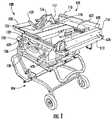
- FIG. 1depicts a top perspective view of a table saw mounted to a wheeled stand
- FIG. 2depicts a side plan view of the right side of the table saw of FIG. 1 with the housing, bevel plate, and workpiece support surface removed and the height adjust carriage at an upper position;
- FIG. 3depicts a side plan view of the left side of the table saw of FIG. 1 with the housing, workpiece support surface, and bevel plate removed;
- FIG. 4is a schematic block diagram of the electrical system of the table saw of FIG. 1 ;
- FIG. 5depicts a side perspective view of the human machine interface (HMI) of FIG. 1 ;
- FIG. 6depicts an exploded view of the internal components of the HMI of FIG. 5 ;
- FIG. 7is an exploded view of the components of the saw control unit of the table saw of FIG. 1 ;
- FIG. 8depicts a side perspective view of the carriage of the table saw of FIG. 1 ;
- FIG. 9is a perspective view of the control unit PCB and the wireless communication module of the table saw of FIG. 1 ;
- FIG. 10is a perspective view of the cover of the housing of the control unit depicted in FIG. 7 .
- the table saw assembly 100includes a table saw 102 , in this case, mounted to a wheeled stand 104 .
- the table saw 102includes a base housing 106 which spaces a workpiece support surface 108 , workbench or the ground in order to allow for blade adjustment.
- a cutting assemblyis supported within the base housing 106 .
- the cutting assemblyis supported from the work surface 108 within the base housing 106 .
- the cutting assemblyincludes a motor 112 , a blade 118 , and a carriage 134 .
- the motor 112is configured to receive power from a power supply ( FIG. 2 ) for driving the blade 118 .
- the blade 118extends upwardly through an opening in the workpiece support surface 108 for cutting a workpiece supported thereon.
- the cutting assembly carriage 134operably supports the cutting assembly within the base 106 .
- the cutting assembly carriage 134may be configured to enable the blade 118 to beveled to perform beveled cutting operations.
- a human machine interface (HMI) unit 124is provided at a front portion of the table saw 102 .
- An angle indicator 130 located adjacent to the HMI unit 124indicates the angle of the blade 118 with respect to the workpiece support surface 108 .
- a bevel adjust lock 132may be used to establish the angle of the blade 118 with respect to the workpiece support surface 108 by pivoting the carriage 134 (shown in FIG. 2 ) within the base 106 . The carriage 134 is then clamped between the bevel adjust lock 132 and a bevel clamp 133 (see FIG. 3 ).
- a height adjust wheel 136is used to adjust the height of the blade 118 above the workpiece support surface 108 (not shown in FIG. 3 ).
- Rotation of the height adjust wheel 136rotates a bevel gear 138 which is engaged with a threaded rod 140 .
- the threaded rod 140is thus forced to rotate either clockwise or counterclockwise, depending upon the direction in which the height adjust wheel 136 is rotated.
- the threaded rod 140threadedly engages a height adjust carriage 142 .
- the threaded rod 140engages a threaded bushing 152 of the height adjust carriage 142 .
- the height adjust carriage 142is thus forced to move upwardly and downwardly as the threaded rod 140 rotates.
- FIG. 4is a schematic depiction of relevant portions of the electrical system of the table saw assembly 100 .
- the electrical systemincludes a saw control unit (SCU) 400 , a power distribution unit 402 , the human machine interface (HMI) 124 , and a wireless communication module 404 .
- the saw control unit 400includes components used to control the table saw assembly, such as a processor, memory and the like.
- the saw control unit 400is implemented on a printed circuit board (PCB) 406 .
- Other systems 408 of the table sawmay also be implemented on the PCB such as an object detection system which enables the detecting or sensing of the proximity or contact of some appendage of an operator with some part of the equipment so that a safety measure may be taken.
- a separate PCB 410supports a power supply 412 and a control TRIAC 414 .
- the power supply 412receives an alternating current (AC) electrical power signal from an external power source, such as a generator or electrical utility provider, and supplies electrical power to the motor 112 through the TRIAC 414 .
- the power supply 412is a switched power supply that converts the AC power signal from an external power source to a direct current (DC) electrical power signal at one or more voltage levels to supply power to the controller 400 and other components of the system.
- the separate PCBs 406 , 410for the controls and power isolate the control unit 400 from the power supply 412 and TRIAC 414 to improve cooling of the digital electronics in the control unit 400 and to isolate the control unit 400 from electrical noise.
- the HMI 124includes at least one output device configured to provide some form of feedback to an operator of the table saw in the form of a visual indicator, audible signal, and the like.
- the HMI 124may include input devices, such as switches, buttons, and the like, that enable operator interaction with the control unit.
- the HMIis a permanent fixture of the table saw.
- the wireless communication module 404enables the operator to interact with the control unit 400 using external devices.
- the wireless communication module 404includes an antenna and a wireless transceiver that provides a wireless communication channel via which an external electronic device, such as a smartphone, tablet, portable notebook computer, or other mobile electronic device receives data from the saw control unit and optionally transmits information to the saw control unit.
- an external electronic devicesuch as a smartphone, tablet, portable notebook computer, or other mobile electronic device receives data from the saw control unit and optionally transmits information to the saw control unit.
- the HMI 124is shown in greater detail in FIGS. 5 and 6 .
- the HMI unit 124includes a housing 500 and a plurality of feedback or status indicators 502 .
- the status indicators 502are illuminated by four LEDs 504 on a printed circuit board (PCB) 506 .
- the LEDS 504are each provided as a colored LED having a color different from the other of the LEDSs.
- the PCB 506is supported by a support 508 which is attached to the housing 500 .
- the status indicators 502are used to provide desired alerts or status indicators to a user.
- the status indicators 502indicate power available, safety system in bypass, safety or system error which is correctable by the user, and safety or system error which is correctable by a service center.
- more or fewer status indicators 502are provided.
- the construction of the HMI 124enables viewing of the status indicators 502 even in bright sunlight.
- the PCB 406 for the control unit 400is provided on the table saw in a manner and location so as to protect the PCB 406 from external influences, such as vibrations, electrical interference, signal noise, and the like.
- the PCB 406is provided in a control unit housing 700 which is mounted onto the carriage 134 , as best seen in FIG. 3 .
- the control unit housing 700 and PCB 406are shown in greater detail in FIGS. 7 and 8 .
- the control unit housing 700includes a base housing member 702 and a cover member 704 .
- the base housing member 702is fastened to the carriage 134 .
- the PCB 406is fastened to the base housing member 702 , and the cover 704 is secured over the PCB 406 . This position is convenient for wire routing.
- a cable 706extends from the control unit housing 700 which is used to connect the PCB 406 to the power distribution system.
- the wireless communication module 404is a removable module that enables data to be transmitted and received wirelessly.
- the wireless communication module 404includes an antenna and a wireless transceiver.
- the configuration of the antenna and the transceiverdepends on the type of wireless communication implemented.
- the wireless communication protocol that is implementedcan be near field communication (NFC), Bluetooth, IEEE 802.11 protocol family compatible (“Wi-Fi”), or other suitable short-range wireless protocols.
- the wireless communication module 404is configured to be easily installed and removed from the table saw as a singular device. Different communication modules may be configured to utilize different communication protocols or may have updated hardware while maintaining the same connection interface for the dock. Having a removable configuration enables different communication modules to be swapped into and out of the table saw in a quick and simple manner.
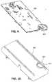
- the table sawincludes a dock 420 for the wireless communication module.
- the dock 420is configured complementarily with respect to the wireless communication module 404 . Therefore, the size, shape and design of the dock 420 depends on the size, shape and design of the communication module 404 .
- the wireless communication module 404comprises a small circular disc shaped object.
- the dock 420comprises a circular wall 422 ( FIG. 10 ) which surrounds a space sized to snugly accommodate the circular disc.
- a cap 424is provided that attaches to the wall and encloses the space thereby providing security and protection for the wireless communication module.
- the dockmay be provided at any suitable location on the table saw that can be accessed when needed to remove/replace a wireless communication module.
- the wireless communication module 404may be provided on an exterior surface of the control unit housing 700 , and in particular, the cover 704 , where it can be in close proximity to the PCB 406 .
- the dock wall 422may be formed integrally with the control unit housing 704 .
- the dock 422may comprise a separate structure which is attached to the control unit housing 704 .
- the dockmay be in another part of the saw, such as the base 106 , and connected to the PBCA 406 via a cable.
- the dock 420includes connection terminals that enable the wireless communication module 404 to be electrically and operably connected to the PCB 406 when the module is seated in the docking position.
- the dock 420 and the module 404are provided with complementary connection terminals which cooperate to establish the appropriate connection when the module is received in the dock. Any suitable type of connection may be used.
- a sim card connectoris used to establish a connection between the wireless communication module 404 and the PCB 406 .
- the wireless communication module 404enables wireless communication between the saw control unit and external electronic devices, such as smartphones, tablets, portable notebook computers, and the like.
- a smartphonereceives diagnostic data from the saw and a software application that is run on the smartphone displays detailed diagnostic information to an operator or maintenance technician to assist in maintenance of the saw.
- the software applicationoptionally enables the operator to input configuration information for operational parameters of the saw that are not directly accessible through the simplified HMI 124 .
- the software applicationenables the operator to input a maximum RPM rate for the motor 112 and blade.
- the software applicationenables the operator to transmit an identifier for a type of material that the saw will cut during operation, such as different types of wood, ceramics, plastics, and the like.
- the sawincludes a lockout mechanism to prevent operation of the saw unless a mobile electronic device with an appropriate cryptographic key is within a predetermined distance of the saw.
- the mobile electronic devicetransmits an encrypted authorization code to the saw in response to a query from the saw to unlock the saw for operation.
- a subsequent queryfails and the saw remains inactive.
Landscapes
- Engineering & Computer Science (AREA)
- Mechanical Engineering (AREA)
- Life Sciences & Earth Sciences (AREA)
- Human Computer Interaction (AREA)
- Manufacturing & Machinery (AREA)
- Physics & Mathematics (AREA)
- General Physics & Mathematics (AREA)
- Automation & Control Theory (AREA)
- Wood Science & Technology (AREA)
- Forests & Forestry (AREA)
- Sawing (AREA)
Abstract
Description
Claims (12)
Priority Applications (4)
| Application Number | Priority Date | Filing Date | Title |
|---|---|---|---|
| US15/946,543US10543543B2 (en) | 2018-04-05 | 2018-04-05 | Advanced saw user interface system |
| TW108111714ATW201943491A (en) | 2018-04-05 | 2019-04-02 | Advanced saw user interface system |
| DE102019204735.1ADE102019204735A1 (en) | 2018-04-05 | 2019-04-03 | Modern saw user interface system |
| CN201910271299.7ACN110340992B (en) | 2018-04-05 | 2019-04-04 | Advanced saw user interface system |
Applications Claiming Priority (1)
| Application Number | Priority Date | Filing Date | Title |
|---|---|---|---|
| US15/946,543US10543543B2 (en) | 2018-04-05 | 2018-04-05 | Advanced saw user interface system |
Publications (2)
| Publication Number | Publication Date |
|---|---|
| US20190308260A1 US20190308260A1 (en) | 2019-10-10 |
| US10543543B2true US10543543B2 (en) | 2020-01-28 |
Family
ID=67991984
Family Applications (1)
| Application Number | Title | Priority Date | Filing Date |
|---|---|---|---|
| US15/946,543Active2038-04-09US10543543B2 (en) | 2018-04-05 | 2018-04-05 | Advanced saw user interface system |
Country Status (4)
| Country | Link |
|---|---|
| US (1) | US10543543B2 (en) |
| CN (1) | CN110340992B (en) |
| DE (1) | DE102019204735A1 (en) |
| TW (1) | TW201943491A (en) |
Families Citing this family (3)
| Publication number | Priority date | Publication date | Assignee | Title |
|---|---|---|---|---|
| CA3111665A1 (en)* | 2020-03-09 | 2021-09-09 | Bid Group Technologies Ltd. | System and method for identifying a machine tool having processed a wood piece |
| US20230405860A1 (en)* | 2020-11-06 | 2023-12-21 | Sawstop Holding Llc | Control systems for power tools |
| CN117882579B (en)* | 2024-03-15 | 2024-05-28 | 山东省林业科学研究院 | A forestry chain saw tooth cleaning device |
Citations (10)
| Publication number | Priority date | Publication date | Assignee | Title |
|---|---|---|---|---|
| US7137327B2 (en) | 2002-10-31 | 2006-11-21 | Black & Decker Inc. | Riving knife assembly for a dual bevel table saw |
| US7680546B2 (en)* | 2004-05-04 | 2010-03-16 | Fisher-Rosemount Systems, Inc. | Graphic element with multiple visualizations in a process environment |
| US20110100183A1 (en) | 2009-11-03 | 2011-05-05 | John Tomaino | Table saw blade height and angle adjustment mechanism |
| US20130131844A1 (en)* | 2009-10-14 | 2013-05-23 | Fisher-Rosemount Systems, Inc. | Method for Selecting Shapes in a Graphical Display |
| US20140318342A1 (en) | 2013-03-13 | 2014-10-30 | Robert Bosch Gmbh | Adjustment and Control Features for a Power Tool |
| US20150277431A1 (en)* | 2014-04-01 | 2015-10-01 | The M. K. Morse Company | Saw data acquisition system and method of operating a saw |
| US20160263762A1 (en)* | 2015-03-12 | 2016-09-15 | Robert Bosch Tool Corporation | System and Method for Object and Operator Profiling in an Object Detection System in a Saw |
| US20160263768A1 (en)* | 2015-03-12 | 2016-09-15 | Robert Bosch Tool Corporation | Electrical Configuration for Object Detection System in a Saw |
| US20160265763A1 (en) | 2015-03-12 | 2016-09-15 | Robert Bosch Tool Corporation | User Interface System in a Table Saw |
| US20180297228A1 (en)* | 2014-07-31 | 2018-10-18 | Usnr, Llc | Dynamically directed workpiece positioning system |
Family Cites Families (8)
| Publication number | Priority date | Publication date | Assignee | Title |
|---|---|---|---|---|
| US20100018609A1 (en)* | 2006-04-26 | 2010-01-28 | Demain Technology Pty Ltd. | Power Tool |
| JP2010280012A (en)* | 2009-06-02 | 2010-12-16 | Makita Corp | Flip-over saw |
| CN202059402U (en)* | 2011-04-15 | 2011-11-30 | 弘邺科技有限公司 | Wireless transmission device |
| TWM422243U (en)* | 2011-09-13 | 2012-02-01 | Ud Electronic Corp | Wireless communication apparatus |
| WO2015094853A1 (en)* | 2013-12-16 | 2015-06-25 | Robert Bosch Gmbh | Miter saw including front accessible bevel lock system |
| WO2016183390A1 (en)* | 2015-05-13 | 2016-11-17 | Taktia Llc | Systems, methods and apparatus for guided tools |
| CN106487616A (en)* | 2015-09-01 | 2017-03-08 | 吴秋锋 | Update standby interface method and Wireless Telecom Equipment that application icon is located |
| CN205950895U (en)* | 2016-08-30 | 2017-02-15 | 广东丰之林木工艺品有限公司 | Novel sliding table saw |
- 2018
- 2018-04-05USUS15/946,543patent/US10543543B2/enactiveActive
- 2019
- 2019-04-02TWTW108111714Apatent/TW201943491A/enunknown
- 2019-04-03DEDE102019204735.1Apatent/DE102019204735A1/enactivePending
- 2019-04-04CNCN201910271299.7Apatent/CN110340992B/enactiveActive
Patent Citations (11)
| Publication number | Priority date | Publication date | Assignee | Title |
|---|---|---|---|---|
| US7137327B2 (en) | 2002-10-31 | 2006-11-21 | Black & Decker Inc. | Riving knife assembly for a dual bevel table saw |
| US7680546B2 (en)* | 2004-05-04 | 2010-03-16 | Fisher-Rosemount Systems, Inc. | Graphic element with multiple visualizations in a process environment |
| US20130131844A1 (en)* | 2009-10-14 | 2013-05-23 | Fisher-Rosemount Systems, Inc. | Method for Selecting Shapes in a Graphical Display |
| US20110100183A1 (en) | 2009-11-03 | 2011-05-05 | John Tomaino | Table saw blade height and angle adjustment mechanism |
| US20140318342A1 (en) | 2013-03-13 | 2014-10-30 | Robert Bosch Gmbh | Adjustment and Control Features for a Power Tool |
| US20150277431A1 (en)* | 2014-04-01 | 2015-10-01 | The M. K. Morse Company | Saw data acquisition system and method of operating a saw |
| US20180297228A1 (en)* | 2014-07-31 | 2018-10-18 | Usnr, Llc | Dynamically directed workpiece positioning system |
| US20160263762A1 (en)* | 2015-03-12 | 2016-09-15 | Robert Bosch Tool Corporation | System and Method for Object and Operator Profiling in an Object Detection System in a Saw |
| US20160263768A1 (en)* | 2015-03-12 | 2016-09-15 | Robert Bosch Tool Corporation | Electrical Configuration for Object Detection System in a Saw |
| US20160265763A1 (en) | 2015-03-12 | 2016-09-15 | Robert Bosch Tool Corporation | User Interface System in a Table Saw |
| US10322522B2 (en)* | 2015-03-12 | 2019-06-18 | Robert Bosch Tool Corporation | Electrical configuration for object detection system in a saw |
Also Published As
| Publication number | Publication date |
|---|---|
| DE102019204735A1 (en) | 2019-10-10 |
| TW201943491A (en) | 2019-11-16 |
| CN110340992B (en) | 2022-04-19 |
| CN110340992A (en) | 2019-10-18 |
| US20190308260A1 (en) | 2019-10-10 |
Similar Documents
| Publication | Publication Date | Title |
|---|---|---|
| US10543543B2 (en) | Advanced saw user interface system | |
| CN108495736B (en) | Anti-theft module for a battery-operated electric power tool and battery-operated electric power tool with an anti-theft module | |
| US9700997B2 (en) | Hand power tool | |
| EP2870537B1 (en) | An interface for a power tool | |
| CN103886247B (en) | System with central authorization management unit and tool device | |
| SE1251416A1 (en) | Tool | |
| KR102013012B1 (en) | Portable-type operation instruction input device and device provided with portable-type operation instruction input device | |
| US20200235643A1 (en) | Power tool user interfaces | |
| US9606230B2 (en) | Optoelectronic sensor and method for detecting objects in a monitored zone | |
| US9914192B2 (en) | Tooling system with visual identification of attached component | |
| CN110650820B (en) | Method for detecting at least one characteristic variable of at least one tool | |
| US20060097860A1 (en) | Device for communicating with a system | |
| US20210078182A1 (en) | Robot system and method of controlling the same | |
| EP3439747B1 (en) | Fire suppression system modules and methods of sealing | |
| US11902851B2 (en) | Smart cord for corded power tools | |
| CN110650822A (en) | Electronic module, in particular for a hand-held power tool | |
| US10684601B2 (en) | Machine control and data logging station | |
| TWM567166U (en) | Torque wrench settable by smart phone | |
| CN110650190A (en) | Environmental condition automatic control switch system | |
| US20020070698A1 (en) | Drive system having at least one electric motor | |
| US20190384359A1 (en) | Holding Device for a Handheld Computer Unit for Controlling a Machine | |
| TW201914768A (en) | Torque wrench set by smart phone capable of achieving effects of simple and accurate setting of a preset torque value and convenient adjustment | |
| CN215646494U (en) | Adjusting device for adjusting rotation angle of motor shaft | |
| KR100634823B1 (en) | Industrial computer device | |
| NO20231008A1 (en) | A system for activation or deactivation of a power supply from an electrical unit |
Legal Events
| Date | Code | Title | Description |
|---|---|---|---|
| FEPP | Fee payment procedure | Free format text:ENTITY STATUS SET TO UNDISCOUNTED (ORIGINAL EVENT CODE: BIG.); ENTITY STATUS OF PATENT OWNER: LARGE ENTITY | |
| AS | Assignment | Owner name:ROBERT BOSCH GMBH, GERMANY Free format text:ASSIGNMENT OF ASSIGNORS INTEREST;ASSIGNORS:LALIBERTE, ERIC R.;TAYLOR, BRIAN C.;REEL/FRAME:046915/0175 Effective date:20180912 Owner name:ROBERT BOSCH TOOL CORPORATION, ILLINOIS Free format text:ASSIGNMENT OF ASSIGNORS INTEREST;ASSIGNORS:LALIBERTE, ERIC R.;TAYLOR, BRIAN C.;REEL/FRAME:046915/0175 Effective date:20180912 | |
| STPP | Information on status: patent application and granting procedure in general | Free format text:NOTICE OF ALLOWANCE MAILED -- APPLICATION RECEIVED IN OFFICE OF PUBLICATIONS | |
| STPP | Information on status: patent application and granting procedure in general | Free format text:PUBLICATIONS -- ISSUE FEE PAYMENT RECEIVED | |
| STCF | Information on status: patent grant | Free format text:PATENTED CASE | |
| MAFP | Maintenance fee payment | Free format text:PAYMENT OF MAINTENANCE FEE, 4TH YEAR, LARGE ENTITY (ORIGINAL EVENT CODE: M1551); ENTITY STATUS OF PATENT OWNER: LARGE ENTITY Year of fee payment:4 |