US10543375B2 - Wearable medical system monitoring blood-related parameter - Google Patents
Wearable medical system monitoring blood-related parameterDownload PDFInfo
- Publication number
- US10543375B2 US10543375B2US16/011,794US201816011794AUS10543375B2US 10543375 B2US10543375 B2US 10543375B2US 201816011794 AUS201816011794 AUS 201816011794AUS 10543375 B2US10543375 B2US 10543375B2
- Authority
- US
- United States
- Prior art keywords
- person
- electrode
- certain electrode
- support structure
- electrodes
- Prior art date
- Legal status (The legal status is an assumption and is not a legal conclusion. Google has not performed a legal analysis and makes no representation as to the accuracy of the status listed.)
- Active
Links
Images


Classifications
- A—HUMAN NECESSITIES
- A61—MEDICAL OR VETERINARY SCIENCE; HYGIENE
- A61N—ELECTROTHERAPY; MAGNETOTHERAPY; RADIATION THERAPY; ULTRASOUND THERAPY
- A61N1/00—Electrotherapy; Circuits therefor
- A61N1/18—Applying electric currents by contact electrodes
- A61N1/32—Applying electric currents by contact electrodes alternating or intermittent currents
- A61N1/38—Applying electric currents by contact electrodes alternating or intermittent currents for producing shock effects
- A61N1/39—Heart defibrillators
- A61N1/3918—Heart defibrillators characterised by shock pathway, e.g. by electrode configuration
- A61B5/0408—
- A—HUMAN NECESSITIES
- A61—MEDICAL OR VETERINARY SCIENCE; HYGIENE
- A61B—DIAGNOSIS; SURGERY; IDENTIFICATION
- A61B5/00—Measuring for diagnostic purposes; Identification of persons
- A61B5/24—Detecting, measuring or recording bioelectric or biomagnetic signals of the body or parts thereof
- A61B5/25—Bioelectric electrodes therefor
- A61B5/251—Means for maintaining electrode contact with the body
- A61B5/256—Wearable electrodes, e.g. having straps or bands
- A—HUMAN NECESSITIES
- A61—MEDICAL OR VETERINARY SCIENCE; HYGIENE
- A61B—DIAGNOSIS; SURGERY; IDENTIFICATION
- A61B5/00—Measuring for diagnostic purposes; Identification of persons
- A61B5/24—Detecting, measuring or recording bioelectric or biomagnetic signals of the body or parts thereof
- A61B5/25—Bioelectric electrodes therefor
- A61B5/279—Bioelectric electrodes therefor specially adapted for particular uses
- A61B5/28—Bioelectric electrodes therefor specially adapted for particular uses for electrocardiography [ECG]
- A—HUMAN NECESSITIES
- A61—MEDICAL OR VETERINARY SCIENCE; HYGIENE
- A61B—DIAGNOSIS; SURGERY; IDENTIFICATION
- A61B5/00—Measuring for diagnostic purposes; Identification of persons
- A61B5/68—Arrangements of detecting, measuring or recording means, e.g. sensors, in relation to patient
- A61B5/6801—Arrangements of detecting, measuring or recording means, e.g. sensors, in relation to patient specially adapted to be attached to or worn on the body surface
- A61B5/683—Means for maintaining contact with the body
- A61B5/6831—Straps, bands or harnesses
- A—HUMAN NECESSITIES
- A61—MEDICAL OR VETERINARY SCIENCE; HYGIENE
- A61B—DIAGNOSIS; SURGERY; IDENTIFICATION
- A61B5/00—Measuring for diagnostic purposes; Identification of persons
- A61B5/68—Arrangements of detecting, measuring or recording means, e.g. sensors, in relation to patient
- A61B5/6801—Arrangements of detecting, measuring or recording means, e.g. sensors, in relation to patient specially adapted to be attached to or worn on the body surface
- A61B5/6843—Monitoring or controlling sensor contact pressure
- A—HUMAN NECESSITIES
- A61—MEDICAL OR VETERINARY SCIENCE; HYGIENE
- A61N—ELECTROTHERAPY; MAGNETOTHERAPY; RADIATION THERAPY; ULTRASOUND THERAPY
- A61N1/00—Electrotherapy; Circuits therefor
- A61N1/18—Applying electric currents by contact electrodes
- A61N1/32—Applying electric currents by contact electrodes alternating or intermittent currents
- A61N1/38—Applying electric currents by contact electrodes alternating or intermittent currents for producing shock effects
- A61N1/39—Heart defibrillators
- A61N1/3904—External heart defibrillators [EHD]
- A—HUMAN NECESSITIES
- A61—MEDICAL OR VETERINARY SCIENCE; HYGIENE
- A61N—ELECTROTHERAPY; MAGNETOTHERAPY; RADIATION THERAPY; ULTRASOUND THERAPY
- A61N1/00—Electrotherapy; Circuits therefor
- A61N1/18—Applying electric currents by contact electrodes
- A61N1/32—Applying electric currents by contact electrodes alternating or intermittent currents
- A61N1/38—Applying electric currents by contact electrodes alternating or intermittent currents for producing shock effects
- A61N1/39—Heart defibrillators
- A61N1/3993—User interfaces for automatic external defibrillators
- A—HUMAN NECESSITIES
- A61—MEDICAL OR VETERINARY SCIENCE; HYGIENE
- A61B—DIAGNOSIS; SURGERY; IDENTIFICATION
- A61B5/00—Measuring for diagnostic purposes; Identification of persons
- A61B5/02—Detecting, measuring or recording for evaluating the cardiovascular system, e.g. pulse, heart rate, blood pressure or blood flow
- A61B5/0205—Simultaneously evaluating both cardiovascular conditions and different types of body conditions, e.g. heart and respiratory condition
- A—HUMAN NECESSITIES
- A61—MEDICAL OR VETERINARY SCIENCE; HYGIENE
- A61B—DIAGNOSIS; SURGERY; IDENTIFICATION
- A61B7/00—Instruments for auscultation
Definitions
- SCASudden Cardiac Arrest
- ICDImplantable Cardioverter Defibrillator
- ECGelectrocardiogram
- a wearable defibrillator systemtypically includes a vest or harness that is worn by the person.
- the systemincludes a defibrillator and electrodes that are attached to the vest or harness.
- the systemmonitor the person's ECG via the electrodes continuously. If a heart tachyarrhythmia is detected, then the defibrillator delivers the appropriate electrical discharge through the heart.
- a root of the discomfortis from the fact that the electrodes of the wearable system have to be making good electrical contact continuously with the person's skin, so that the person's ECG can be monitored continuously.
- the problemhas been addressed, for example in U.S. Pat. No. 6,546,285, titled LONG TERM WEAR ELECTRODE FOR DEFIBRILLATION SYSTEM.
- the latter patentteaches, among other things, to move the electrodes to different places on the person's skin at different times, and/or to use a hydrogel for the electrodes that includes a therapeutic agent which promotes skin health.
- a wearable defibrillator systemincludes a support structure with one or more electrodes in an unbiased state.
- a monitoring devicemonitors, for the long term, a parameter of the person that is not the person's ECG; rather, the monitored parameter can be the person's motion, or a physiological parameter.
- a value of the monitored parameterreaches a threshold, such as when the person is having an actionable episode, the electrode becomes mechanically biased against the person's body, for making good electrical contact. Then, if necessary, the person can be given electrical therapy, such as defibrillation.
- An advantage over the prior artis that, while the wearable defibrillator system does require long-term wearing to protect the person, wearing itself does not require that one or more of its electrodes be making good electrical contact with the person's skin for the long term. The contact is made by the biasing, when the system otherwise detects that the person is having an actionable episode. Until then, however, the electrodes can be worn more loosely, sometimes similarly with how loose the other garments feel to the wearer. This can reduce the person's aversion to wearing the defibrillation system, who might in turn comply more with the instruction to wear it.
- FIG. 1is a diagram of components of a wearable defibrillator system, according to embodiments.
- FIG. 2is a diagram showing sample thresholds for making decisions according to embodiments.
- FIG. 3is a diagram showing components of an external defibrillator, such as the one shown in FIG. 1 , which is made according to embodiments.
- FIG. 4Ais a diagram showing an electrode, such as a possible embodiment of an electrode of FIG. 1 , which is not being biased towards the body of the wearer according to embodiments.
- FIG. 4Bis a diagram showing the electrode of FIG. 4A , but in which the electrode is instead being biased towards the body of the wearer according to embodiments.
- FIG. 5is a flowchart for illustrating methods according to embodiments.
- FIG. 6is a flowchart segment for describing additional optional operations according to embodiments.
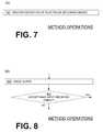
- FIG. 7is a flowchart segment for describing an additional optional operation according to embodiments.
- FIG. 8is a flowchart segment for describing additional optional operations according to embodiments.
- FIG. 9is another flowchart for illustrating methods according to embodiments.
- FIG. 10is one more flowchart for illustrating methods according to embodiments.
- Embodimentsinclude wearable defibrillator systems, which are configured to be worn by a person.
- the personis sometimes called also a patient and/or a wearer.
- the person wearing the systemmay be moving, for example during their daily activities. As they move, any garments they wear may shift with respect to their body.
- the wearable defibrillator systems of the embodimentsare configured to defibrillate the person by delivering electrical charge to the person's body.
- Systems according to embodimentsmay include a support structure, which is configured to be worn by the person.
- the support structurecan be any structure suitable for wearing, such as a harness, a vest, a garment, and so on.
- the support structurecan be implemented in a single component, or multiple components.
- a support structuremay have a top component resting on the shoulders, for ensuring that the defibrillation electrodes will be in the right place for defibrillating, and a bottom component resting on the hips, for carrying the weight of the defibrillator.
- FIG. 1is presented as an example of only some embodiments.
- FIG. 1is a diagram of components of a wearable defibrillator system.
- a generic support structure 170is shown relative to the body of a person 82 .
- Structure 170could be a harness, vest, garment, and so on. It could be implemented in a single component, or multiple components, as per the above.
- Structure 170is wearable by person 82 , but the manner of wearing it is not depicted, as structure 170 is depicted only generically in FIG. 1 .
- Systems according to embodimentsmay also include a monitoring device, which can be used for determining whether intervention by the system will be necessary.
- a monitoring device 180is also shown in FIG. 1 .
- the monitoring deviceis coupled to the support structure, physically and/or in terms of electrical communication with other elements coupled to the support structure, as will be deemed necessary by a person skilled in the art in view of this disclosure.
- the value of the parametercan be used to make a decision.
- the decisioncan be made when a threshold is reached, or exceeded.
- the determination of whether the threshold is reached or exceededcan be made as is known in the art. For example, in embodiments where a value is encoded in a voltage level, the determination can be made by a comparator that is tripped when the voltage level exceeds the applicable threshold voltage level.
- the systemcan optionally include a logic device, such as a processor, and the value is encoded in as a number.
- the logic devicecan be is configured to determine when the parameter has reached or exceeded the appropriate threshold.
- FIG. 2is a diagram showing possible thresholds 220 , 250 , 285 for making decisions according to embodiments. Examples of use of these thresholds are described later in this document, also in terms of flowcharts. It will be appreciated that not all of these thresholds are used in every embodiment.
- Thresholds 220 , 250 , 285are shown on a single scale, according to relative potential severity of the patient's condition. Even though shown in a single scale, it should be remembered that these thresholds may be established for the same or different patient parameters, for use by the same or different elements of embodiments. For example, the thresholds can be either for the parameter monitored by the monitoring device, or by another monitoring device, or for an ECG reading of the person obtained by electrodes, and so on. Moreover, there can be same or different results if the thresholds are reached or exceeded.
- Embodimentsescalate the checking and operations, such as along this scale, as they detect the patient's condition to be more severe, in ways that the system could address by administering electrical therapy.
- Threshold 220is a response-check threshold, above which the decision can be that the person be asked to respond, in some manner, as to whether they are fine. A person who responds they are fine will likely not need electrical therapy at this time.
- Threshold 250is an ECG-check threshold, above which the decision can be that an ECG reading of the person needs to be taken for certainty. If the person's ECG turns out to be a non-shockable rhythm, such as a normal sinus rhythm, then the system need not administer electrical therapy.
- Threshold 285is a defibrillation advised threshold, above which a defibrillate decision is made, and the person is defibrillated. Below the lowest of thresholds, which in FIG. 2 is threshold 220 , the patient can be presumed to be not in danger, and the decision can be that no action is taken, and there is no escalation.
- the monitoring deviceits monitored parameters can be a motion of the person's body, in some embodiments.
- the monitoring devicemay include a motion detector, which can be made in many ways as is known in the art.
- the monitoring devicecould include a GPS, which informs of the location, and the rate of change of location over time.
- Many motion detectorsoutput a motion signal that is indicative of the motion of the detector, and thus of the person's body.
- the thresholdcan sometimes be adjusted according to an output of the motion detector itself.
- the thresholdscan be adjusted also with regard to additional parameters that can be monitored.
- One such additional parametercan be the time of day, which can be monitored by a clock in a processor of the system. For example, the person is expected to be sleeping during more of the night hours.
- the monitored parameteris a physiological parameter of the person.
- the physiological parametercan be any one that would help detect whether the person is in need of electrotherapy by the wearable defibrillation system.
- Example such parametersinclude the person's blood oxygen level, blood flow, blood pressure, blood perfusion, pulsatile change in light transmission or reflection properties of perfused tissue, heart sounds, breathing sounds and pulse.
- the monitoring devicecould be a pulse oximeter, a Doppler device for detecting blood flow, a cuff for detecting blood pressure, illumination detectors and maybe sources for detecting color change in tissue, a device that can detect artery wall movement, a device with a microphone, and so on. Pulse detection is taught at least in Physio-Control's U.S. Pat.
- both the person's physiological parameter and motioncan be monitored in combination.
- the value of the physiological parameterbecomes better informed from the motion profile, as is the appropriate threshold for determining whether an actionable episode is taking place so as to escalate.
- the thresholdcan be adjusted accordingly. For example, if the person is running then a somewhat higher pulse rate may be tolerated until a time after they stop, without needing to escalate, and so on.
- Systems according to embodimentsmay also include a capacitor, which can be configured to store an electrical charge.
- the chargeis configured to be delivered to the person's body according to embodiments.
- the capacitoris coupled to the support structure, and the charge is delivered while the person is wearing the support structure.
- the capacitoris implemented as part of a defibrillator, such as sample external defibrillator 100 in FIG. 1 .
- the defibrillatorcan be coupled to the support structure, such as defibrillator 100 is coupled to structure 170 in FIG. 1 .
- a full defibrillatormay not be implemented, such as in instances where the capacitor charge is controlled to be delivered to the person remotely, and so on.
- FIG. 3is a diagram showing components of an external defibrillator 300 made according to embodiments. These components can be, for example, in external defibrillator 100 of FIG. 1 , in the event that defibrillator components beyond the capacitor are provided. These components of FIG. 3 can be provided in a housing 301 , which is also known as casing 301 .
- defibrillator 300is intended for person 380 who would be the wearer, such as person 82 of FIG. 1 .
- defibrillator 300includes the above described monitoring device 325 , which can include any one of a motion sensor, a physiological parameter motion, etc., as per the above.
- the monitoring deviceis provided outside housing 301 , such as monitoring device 180 is shown in the example of FIG. 1 .
- Defibrillator 300typically includes a defibrillation port 310 , such as a socket in housing 301 .
- Defibrillation port 310includes nodes 314 , 318 .
- Defibrillation electrodes 304 , 308which will be described later in more detail, can be plugged in defibrillation port 310 , so as to make electrical contact with nodes 314 , 318 , respectively. It is also possible that defibrillation electrodes can be connected continuously to defibrillation port 310 , instead. Either way, defibrillation port 310 can be used for guiding via electrodes to the wearer the electrical charge that has been stored in energy storage module 350 .
- Defibrillator 300may optionally also have an ECG port 319 in housing 301 , for plugging in ECG electrodes 309 , which are also known as ECG leads. It is also possible that ECG electrodes can be connected continuously to ECG port 319 , instead. ECG electrodes 309 can help sense an ECG signal, e.g. a 12-lead signal, or a signal from a different number of leads, as long as they make good electrical contact with the body of the patient.
- ECG electrodes 309can help sense an ECG signal, e.g. a 12-lead signal, or a signal from a different number of leads, as long as they make good electrical contact with the body of the patient.
- Defibrillator 300also includes a measurement circuit 320 .
- Measurement circuit 320receives physiological signals from ECG port 319 , if provided. Even if defibrillator 300 lacks ECG port 319 , measurement circuit 320 can obtain physiological signals through nodes 314 , 318 instead, when defibrillation electrodes 304 , 308 are attached to the patient. In these cases, a person's ECG signal can be sensed as a voltage difference between electrodes 304 , 308 . Plus, impedance between electrodes 304 , 308 can be sensed for detecting, among other things, whether these electrodes 304 , 308 are not making good electrical contact with the person's body. These physiological signals are sensed, and information about them is rendered by circuit 320 as data, or other signals, etc.
- Defibrillator 300also includes a processor 330 .
- Processor 330may be implemented in any number of ways. Such ways include, by way of example and not of limitation, digital and/or analog processors such as microprocessors and digital-signal processors (DSPs); controllers such as microcontrollers; software running in a machine; programmable circuits such as Field Programmable Gate Arrays (FPGAs), Field-Programmable Analog Arrays (FPAAs), Programmable Logic Devices (PLDs), Application Specific Integrated Circuits (ASICs), any combination of one or more of these, and so on.
- DSPsdigital-signal processors
- controllerssuch as microcontrollers
- software running in a machineprogrammable circuits such as Field Programmable Gate Arrays (FPGAs), Field-Programmable Analog Arrays (FPAAs), Programmable Logic Devices (PLDs), Application Specific Integrated Circuits (ASICs), any combination of one or more of these, and so on.
- Processor 330can be considered to have a number of modules.
- One such modulecan be a detection module 332 .
- Processor 330running detection module 332 , is a sample embodiment of a logic device configured to determine whether the above-described monitored parameter has reached a specific threshold.
- the monitoring parametercan be input from monitoring device 325 , if provided.
- detection module 332can include a ventricular fibrillation (“VF”) detector and the person's sensed ECG from measurement circuit 320 can be used to determine whether the person is experiencing VF. Detecting VF is useful, because VF is a precursor to SCA.
- VFventricular fibrillation
- Another such module in processor 330can be an advice module 334 , which arrives at advice, for example based on outputs of detection module 332 , and/or implements decisions.
- advice module 334can be many types of advice according to embodiments.
- a Shock Advisory Algorithmcan render the advice to shock, as opposed to not shock the person. Such can be, for example, when the person's condition has reached or exceeded defibrillation advised threshold 285 of FIG. 2 . Shocking can be for defibrillation, pacing, and so on.
- the adviceis to shock, some external defibrillator embodiments proceed with shocking, or may advise a remote attendant to do it, and so on.
- the advicecan be to administer CPR, and defibrillator 300 may further issue prompts for it, and so on.
- Defibrillator 300optionally includes also a bias port 392 for exporting biasing signal BA from bias port 392 to a biasing mechanism of the system, which will also be described later.
- Processor 330can include additional modules, such as module 336 , for other functions.
- module 336for other functions.
- monitoring device 325it may be operated in part by processor 330 , etc.
- Defibrillator 300optionally further includes a memory 338 , which can work together with processor 330 .
- Memory 338may be implemented in any number of ways. Such ways include, by way of example and not of limitation, nonvolatile memories (NVM), read-only memories (ROM), random access memories (RAM), any combination of these, and so on.
- NVMnonvolatile memories
- ROMread-only memories
- RAMrandom access memories
- Memory 338if provided, can include programs for processor 330 , and so on. The programs can be operational for the inherent needs of processor 330 , and can also include protocols and ways that decisions can be made by advice module 334 .
- memory 338can store prompts for person 380 , if they are a local rescuer.
- memory 338can store patient data.
- Defibrillator 300may also include a power source 340 .
- power source 340typically includes a battery. Such a battery is typically implemented as a battery pack, which can be rechargeable or not. Sometimes, a combination is used, of rechargeable and non-rechargeable battery packs.
- Other embodiments of power source 340can include AC power override, for where AC power will be available, and so on.
- power source 340is controlled by processor 330 .
- Defibrillator 300additionally includes an energy storage module 350 .
- Module 350is where some electrical energy is stored, when preparing it for sudden discharge to administer a shock. Module 350 can be charged from power source 340 to the right amount of energy, as controlled by processor 330 .
- module 350includes a capacitor 352 , which can be a single capacitor or a system of capacitors, and so on. As described above, capacitor 352 can store the charge for delivering to the patient.
- Defibrillator 300moreover includes a discharge circuit 355 .
- Circuit 355can be controlled to permit the energy stored in module 350 to be discharged to nodes 314 , 318 , and thus also to defibrillation electrodes 304 , 308 .
- Circuit 355can include one or more switches 357 . Those can be made in a number of ways, such as by an H-bridge, and so on.
- Defibrillator 300further includes a user interface 370 for a user 380 .
- User 380can be the wearer, if conscious, or a rescuer.
- the rescuercan be local, such as a bystander who might offer assistance, or a trained person who might arrive after the fact. Alternately the rescuer could be remote, such as a trained person in remote communication with a system according to embodiments, and/or with the wearer.
- User interface 370can be made in any number of ways.
- interface 370may include a screen, to display what is detected and measured, provide visual feedback to the rescuer for their resuscitation attempts, and so on.
- Interface 370may also include a speaker, to issue voice prompts, etc.
- Interface 370may additionally include various controls, such as pushbuttons, keyboards, touchscreens, a microphone, and so on.
- discharge circuit 355can be controlled by processor 330 , or directly by user 380 via user interface 370 , and so on.
- Defibrillator 300can optionally include other components.
- a communication module 390may be provided for communicating with other machines or a remote rescuer 380 .
- Such communicationcan be performed wirelessly, or via wire, or by infrared communication, and so on. This way, data can be communicated, such as patient data, episode information, therapy attempted, CPR performance, and so on.
- Embodiments of the system of the inventionmay additionally include defibrillation electrodes. It will be appreciated that the defibrillation electrodes of embodiments could both deliver a charge, and also serve for sensing the person's ECG. The defibrillation electrodes can deliver to the person electrical charge stored in the capacitor, for restoring their heart rhythm, when the defibrillation electrodes make good electrical contact with the body of the wearer.
- FIG. 1shows an example of defibrillation electrodes 104 , 108 , which are coupled to external defibrillator 100 via electrode leads 105 .
- defibrillator 100can administer, via electrodes 104 , 108 , a brief, strong electric pulse 111 through the body.
- Pulse 111also known as a defibrillation shock, goes also through heart 85 , in an attempt to restart it, for saving the life of person 82 .
- defibrillation electrodes 304 , 308would plug into defibrillation port 310 , so as to make electrical contact with nodes 314 , 318 , respectively.
- Defibrillation electrodes 304 , 308could be similar to defibrillation electrodes 104 , 108 of FIG. 1 .
- Embodiments of the system of the inventionmay additionally include ECG electrodes. If provided, ECG electrodes could be electrically connected for example as seen in FIG. 3 for ECG electrodes 309 .
- either defibrillation electrodesare provided by themselves, or ECG electrodes are provided in addition to defibrillation electrodes.
- An ECG readingcan be provided by either type of electrodes, preferably while they are making good electrical contact with the body of the person, and more particularly the skin.
- all the above mentioned electrodesare not always making good electrical contact with the person's skin.
- at least one of the above-mentioned electrodesalso known as a certain electrode, can be coupled to the support structure such that, while the support structure is worn by the person, the certain electrode is at a so-called unbiased state.
- the certain electrodeis moveable with respect to the person's body, for example as a result of the person's moving around.
- the certain electrodecould contact the person's skin as a regular garment does, for example as does a shirt that is not tightened around the person's body.
- the certain electrodecould shift around the person's skin, and occasionally lose contact with it. In those occasional moments, the electrical impedance between the certain electrode and the patient's skin would become infinite.
- the certain electrodecan be either one of the defibrillation electrodes, or one of the ECG electrodes, if provided.
- the certain electrodecould also apply for a companion electrode that performs a similar function.
- Embodiments of the system of the inventionmay additionally include a first biasing mechanism.
- the first biasing mechanismcan be configured to cause the certain electrode to transition from the above described unbiased state to a so-called biased state.
- the certain electrodeWhen in the biased state, the certain electrode is biased towards the person's body against the support structure.
- the biasingis by a force that causes the certain electrode to be less moveable with respect to the person's body than when in the unbiased state.
- the certain electrodemakes better and/or more reliable electrical contact with the person's skin than in the unbiased state. The better electrical contact can be used for more reliable defibrillation and or receiving ECG signals, as the case may be for the certain electrode.
- the first biasing mechanismcan cause the certain electrode to transition from the unbiased state to the biased state, responsive to a value of the monitored parameter reaching a threshold.
- the first biasing mechanismcan be configured to receive a biasing signal that signifies that the determination has been made that the value of the monitored parameter has reached the applicable threshold, and there will be escalation.
- the first biasing mechanismcan be configured to receive the biasing signal from that logic device. An example was described above for biasing signal BA from the device of FIG. 3 .
- the transitioning from the biased state to the unbiased stateis also called biasing and deployment of the certain electrode. Deployment is for the certain electrode, and possibly also other electrodes of the system. It will be appreciated that deployment in this sense might not necessarily change much the position of the certain electrode with respect to the patient's body, but it will change the force with which it is pushed or biased towards the body.
- the first biasing mechanismcan be made in any way so as to cause pressure to be applied to the certain electrode against the support structure, and therefore bias the certain electrode towards the person's body.
- Various embodiments of the first biasing mechanisminclude a spring that is released, causing the support structure to be tightened around the body, causing a balloon to be inflated, adding pressure to a hydraulic system, applying force such as with an electromagnet, and turning a screw gun arrangement so that turning result in a translation motion.
- the sample embodiment of FIG. 1shows also a biasing mechanism 194 .
- FIG. 4Ais a diagram according to an embodiment.
- a patient 482is wearing a support structure 470 , of which two portions are shown.
- Support structure 470is made according to embodiments and, as with FIG. 1 , it is shown only generically.
- a certain electrode 408could be either a defibrillation electrode or an ECG electrode, and is coupled to support structure 470 in an unbiased state. In the instant of FIG. 4A , certain electrode 408 does not even contact the skin of patient 482 .
- a biasing mechanism 494is also coupled to support structure 470 .
- FIG. 4Bis a diagram showing the same elements as FIG. 4A , except that biasing mechanism 494 exerts a biasing force 496 due to which certain electrode 408 is biased towards patient 482 against support structure 470 .
- certain electrode 408contacts the skin of patient 482 .
- Certain electrode 408is less easily movable in FIG. 4B than in FIG. 4A .
- the first biasing mechanismis preferably made so that it is further reversible, either by the wearer, or by a bystander, or by a remotely monitoring medical professional. Reversing would be upon verifying that there is no actionable episode to be addressed by the system, moves downwards in the scale of FIG. 2 , and is the opposite of escalation. Reversing could be automatically enabled by further functionality. Or, reversing could be implemented by permitting the mechanically reverse motion of what deployed the certain electrode and any other electrodes. Care should be taken that reversing is not suggested prematurely, or by a person who does not understand the function of the system, such as a well-meaning by uninformed bystander.
- any ECG inputs received by the certain electrodepreferably are trusted more when the certain electrode is in the biased state than in the unbiased state.
- an additional, serendipitous check on the patientcan be an ECG reading that is received incidentally while the certain electrode is in the unbiased state and whose content causes alarm.
- Such an ECG readingcan be used in a number of ways, for tentative escalation.
- One exampleis for the biasing mechanism to cause the certain defibrillation electrode to transition to the biased state from the unbiased state responsive to an ECG reading of the person that is received incidentally while the certain electrode is in the unbiased state.
- the certain electrodemakes good electrical contact while biased, i.e. while the biasing mechanism exerts a biasing force.
- the certain electrodeincludes adhesive material.
- the adhesive materialcan be always there, or be deployed right before the biasing. As the biasing mechanism causes the certain electrode to transition from the unbiased state to the biased state by exerting the biasing force, it in turn causes the certain electrode to adhere to the person due to the adhesive material. The electrode can remain adhered even if the biasing mechanism discontinues exerting the biasing force.
- Embodiments of the system of the inventionmay additionally include a memory.
- the memorycan be configured to record various aspects, such as values of the parameter being monitored, an event of a threshold having been reached by the monitored parameter, an event of the certain electrode transitioning to the biased state form the unbiased state, and so on.
- the memorycan be memory 338 .
- Embodiments of the system of the inventionmay further include a user interface.
- the user interfacecan include output devices, such as a speaker, a display, a vibration mechanism etc., plus input devices such as a microphone, buttons, keys, and other implements that a user can activate or deactivate.
- the user interfacecan be configured to issue a query to the person, to verify that they are conscious, and therefore confirm there is no cause for alarm from a detected value of the monitored parameter. Such can be, for example, when the person's condition has reached or exceeded response-check threshold 220 of FIG. 2 . In those instances, embodiments permit the wearer to enter an input in response to the query within a certain time, before the certain electrode transitions from the unbiased state to the biased state.
- the certain electrodecan be configured to transition to the biased state only if a preset acceptable input has not been received in response to the query within a preset time after the query has been issued.
- the user interfacecan be user interface 370 .
- the option of querying the usercan be further coupled with the advent of a serendipitous receipt of an ECG reading whose content causes alarm while the certain electrode is in the unbiased state.
- the user querycan be triggered as above.
- the certain electrodeis a defibrillation electrode.
- the electrical charge stored in the capacitor of the systemis configured to be delivered through the person's body via the certain electrode, and also via another defibrillation electrode.
- defibrillation electrode 108is the certain electrode
- defibrillation electrode 104is the other defibrillation electrode, while no separate ECG electrodes are provided.
- Certain electrode 108can become deployed, as can electrode 104 by a suitable biasing mechanism.
- the certain electrodecan be an ECG electrode.
- one or more ECG electrodesare thus provided above and beyond defibrillation electrodes.
- the one or more ECG electrodescan become deployed, as per the above.
- the defibrillation electrodesWhen ECG electrodes are also provided, there are a number of options about the defibrillation electrodes.
- One optionis for the defibrillation electrodes to be always attached to the patient by how they are coupled to the support structure. This is not very advantageous, however, as the intent is to liberate the person from contact with electrodes for the long-term wear, so as to make compliance more palatable.
- the defibrillation electrodesalso be deployable. More particularly, the defibrillation electrodes can be coupled to the support structure. The coupling can be such that, while the support structure is worn by the person, at least a particular one of the defibrillation electrodes is either at an unbiased state or a biased state. Similarly with the above, when the particular defibrillation electrode is in the unbiased state, it is moveable with respect to the person's body responsive to the person's moving. Moreover, when the particular defibrillation electrode is in the biased state, the particular defibrillation electrode is biased towards the person's body against the support structure so as to be less moveable with respect to the person's body than when in the unbiased state.
- an ECG readingcan advantageously be received also from the particular electrode that is deployed.
- the defibrillation electrodesare also deployable, there are a number of embodiments.
- An embodimentis for at least one of the ECG electrodes to be attached to at least one of the defibrillation electrodes.
- deploying the certain ECG electrode by the first biasing mechanismalso deploys the defibrillation electrode.
- Attachmentcan be implemented in any number of ways.
- the ECG electrodecan be formed integrally with one of the defibrillation electrodes.
- the ECG electrodecan be formed as a segmented electrode with a defibrillation electrode.
- the certain electrodecan also be considered to be the defibrillation electrode, which has the further feature of one or more ECG electrodes attached to it.
- Another embodimentis for at least one of the defibrillation electrodes to be truly distinct from the ECG electrodes.
- This optionhas the advantage that certain types of false alarm will result in deploying only the ECG electrodes upon partial escalation, but not the usually larger defibrillation electrodes.
- This optionalso has the disadvantage that two deployments may be needed, which requires more biasing structures in the system.
- a second biasing mechanismcan be provided for the system, which is distinct from the first biasing mechanism.
- the second biasing mechanismcan be configured to cause the particular defibrillation electrode to transition from its unbiased state to its biased state.
- a defibrillator systemthat is wearable by a person who may be moving, and which includes a support structure and electrodes coupled to the support structure.
- the electrodesare coupled such that, while the support structure is worn by the person, at least a certain one of the electrodes is moveable with respect to the person's body responsive to the person's moving.
- the certain electrodecan be a defibrillation electrode, an ECG electrode, or a combination of the two.
- FIG. 5shows a flowchart 500 for describing methods according to embodiments.
- at least one parameter of the personis monitored, while the person is wearing the support structure.
- the parameteris not an electrocardiogram (“ECG”) of the person.
- ECGelectrocardiogram
- the parameteris a motion of the person's body.
- the parameteris a physiological parameter, which could be one of the person's blood perfusion, blood flow, blood pressure, blood oxygen level, pulsatile change in light transmission/reflection properties of perfused tissue, heart sounds and breathing sounds.
- a next operation 545it is determined whether a threshold has been reached for the monitored parameter. If not, execution returns to operation 510 .
- the certain electrodebecomes biased towards the person's body against the support structure. Accordingly, the certain electrode becomes less moveable with respect to the person's body than previously. Biasing can be by exerting force, with implements such as described above.
- FIG. 6shows a flowchart segment 600 for describing additional optional operations according to embodiments.
- the additional optional operations of flowchart segment 600can be added to other flowcharts in this description.
- an optional operation 684it is inquired whether a defibrillate decision has been made. If not, execution can return to a previous operation. If yes, then according to a next operation 690 , the person is defibrillated.
- FIG. 7shows a flowchart segment 700 for describing additional optional operations according to embodiments.
- the additional optional operations of flowchart segment 700can be added to other flowcharts in this description.
- an indicationis recorded in a memory of an electrode becoming biased. This might have occurred, for example, per the previous operation 582 of FIG. 5 .
- FIG. 8shows a flowchart segment 800 for describing additional optional operations according to embodiments.
- the additional optional operations of flowchart segment 800can be added to other flowcharts in this description.
- a queryis issued to the person.
- the querycan be issued when a parameter has reached or exceeded response-check threshold 220 of FIG. 2 .
- a next operation 840it is inquired whether a preset acceptable input in response to the query has been received timely, for example within a preset time after the query has been issued. If yes, then the person can be presumed to not have had an SCA, and escalation of inquiry or perception of severity of their condition can be forestalled. If not, then further escalation is justified, and other measures can take place, such as biasing one or more electrodes, and so on.
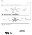
- FIG. 9shows a flowchart 900 for describing a method according to embodiments.
- a parameteris monitored that is not an ECG of the person.
- a next operation 950it is determined whether an ECG-check threshold 250 has been reached for the parameter. If not, execution returns to operation 910 .
- the certain electrodebecomes biased towards the person's body against the support structure. As such, the certain electrode becomes less moveable with respect to the person's body than previously.
- next operation 985it is inquired whether defibrillation is advised. If not, execution can return to operation 910 . If yes, then according to a next operation 990 , the person is defibrillated.
- FIG. 10shows a flowchart 1000 for describing a method according to embodiments.
- Flowchart 1000is for a device that has distinct ECG electrodes from defibrillation electrodes, with distinct respective biasing mechanisms. Unlike the usually large defibrillation electrodes, ECG electrodes maybe harder to aim to suitable locations on the person's skin.
- a parameteris monitored that is not an ECG of the person.
- a next operation 1050it is determined whether an ECG-check threshold 250 has been reached for the parameter. If not, execution returns to operation 1010 .
- the ECG electrodesbecome biased towards the person's body against the support structure. As such, the ECG electrodes become less moveable with respect to the person's body than previously.
- a next operation 1070it is first inquired whether defibrillation is likely advised.
- the first inquiry—also designated as “A” in the flowchart—of this operation 1070is according to ECG readings received from the now biased ECG electrodes.
- the first inquiry of this operation 1070can be more tentative than the upcoming inquiry. If not, execution can return to operation 1010 .
- the defibrillation electrodesbecome biased towards the person's body against the support structure.
- a next operation 1086it is again inquired whether defibrillation is advised.
- the second inquiry—also designated as “B” in the flowchart—of this operation 1086is according to ECG readings received from the now biased defibrillation electrodes, and can be to determine whether threshold 285 has been reached or exceeded. If not, execution can return to operation 1010 . If yes, then according to a next operation 1090 , the person is defibrillated.
- One or more embodiments described hereinmay be implemented fully or partially in software and/or firmware.
- This software and/or firmwaremay take the form of instructions contained in or on a non-transitory computer-readable storage medium. Those instructions may then be read and executed by one or more processors to enable performance of the operations described herein.
- the instructionsmay be in any suitable form, such as but not limited to source code, compiled code, interpreted code, executable code, static code, dynamic code, and the like.
- Such a computer-readable mediummay include any tangible non-transitory medium for storing information in a form readable by one or more computers, such as but not limited to read only memory (ROM); random access memory (RAM); magnetic disk storage media; optical storage media; a flash memory, etc.
- computer-readable mediaincludes computer-storage media.
- computer-storage mediamay include, but are not limited to, magnetic storage devices (e.g., hard disk, floppy disk, and magnetic strips), optical disks (e.g., compact disk [CD] and digital versatile disk [DVD]), smart cards, flash memory devices (e.g., thumb drive, stick, key drive, and SD cards), and volatile and nonvolatile memory (e.g., RAM and ROM).
- embodimentsinclude combinations and sub-combinations of features described herein, including for example, embodiments that are equivalent to: providing or applying a feature in a different order than in a described embodiment, extracting an individual feature from one embodiment and inserting such feature into another embodiment; removing one or more features from an embodiment; or both removing a feature from an embodiment and adding a feature extracted from another embodiment, while providing the advantages of the features incorporated in such combinations and sub-combinations.
Landscapes
- Health & Medical Sciences (AREA)
- Life Sciences & Earth Sciences (AREA)
- Engineering & Computer Science (AREA)
- Public Health (AREA)
- Heart & Thoracic Surgery (AREA)
- Biomedical Technology (AREA)
- Veterinary Medicine (AREA)
- Animal Behavior & Ethology (AREA)
- General Health & Medical Sciences (AREA)
- Cardiology (AREA)
- Medical Informatics (AREA)
- Physics & Mathematics (AREA)
- Biophysics (AREA)
- Pathology (AREA)
- Molecular Biology (AREA)
- Surgery (AREA)
- Radiology & Medical Imaging (AREA)
- Nuclear Medicine, Radiotherapy & Molecular Imaging (AREA)
- Human Computer Interaction (AREA)
- Electrotherapy Devices (AREA)
Abstract
Description
Claims (22)
Priority Applications (2)
| Application Number | Priority Date | Filing Date | Title |
|---|---|---|---|
| US16/011,794US10543375B2 (en) | 2013-04-02 | 2018-06-19 | Wearable medical system monitoring blood-related parameter |
| US16/774,611US11375936B2 (en) | 2013-04-02 | 2020-01-28 | Wearable medical system to monitor a patient parameter |
Applications Claiming Priority (4)
| Application Number | Priority Date | Filing Date | Title |
|---|---|---|---|
| US201361807453P | 2013-04-02 | 2013-04-02 | |
| US13/906,327US9827431B2 (en) | 2013-04-02 | 2013-05-30 | Wearable defibrillator with no long-term ECG monitoring |
| US15/707,896US10022551B1 (en) | 2013-04-02 | 2017-09-18 | Wearable defibrillator with no long-term ECG monitoring |
| US16/011,794US10543375B2 (en) | 2013-04-02 | 2018-06-19 | Wearable medical system monitoring blood-related parameter |
Related Parent Applications (1)
| Application Number | Title | Priority Date | Filing Date |
|---|---|---|---|
| US15/707,896ContinuationUS10022551B1 (en) | 2013-04-02 | 2017-09-18 | Wearable defibrillator with no long-term ECG monitoring |
Related Child Applications (1)
| Application Number | Title | Priority Date | Filing Date |
|---|---|---|---|
| US16/774,611ContinuationUS11375936B2 (en) | 2013-04-02 | 2020-01-28 | Wearable medical system to monitor a patient parameter |
Publications (2)
| Publication Number | Publication Date |
|---|---|
| US20180296846A1 US20180296846A1 (en) | 2018-10-18 |
| US10543375B2true US10543375B2 (en) | 2020-01-28 |
Family
ID=51621576
Family Applications (4)
| Application Number | Title | Priority Date | Filing Date |
|---|---|---|---|
| US13/906,327Active2035-10-18US9827431B2 (en) | 2013-04-02 | 2013-05-30 | Wearable defibrillator with no long-term ECG monitoring |
| US15/707,896ActiveUS10022551B1 (en) | 2013-04-02 | 2017-09-18 | Wearable defibrillator with no long-term ECG monitoring |
| US16/011,794ActiveUS10543375B2 (en) | 2013-04-02 | 2018-06-19 | Wearable medical system monitoring blood-related parameter |
| US16/774,611Active2033-12-20US11375936B2 (en) | 2013-04-02 | 2020-01-28 | Wearable medical system to monitor a patient parameter |
Family Applications Before (2)
| Application Number | Title | Priority Date | Filing Date |
|---|---|---|---|
| US13/906,327Active2035-10-18US9827431B2 (en) | 2013-04-02 | 2013-05-30 | Wearable defibrillator with no long-term ECG monitoring |
| US15/707,896ActiveUS10022551B1 (en) | 2013-04-02 | 2017-09-18 | Wearable defibrillator with no long-term ECG monitoring |
Family Applications After (1)
| Application Number | Title | Priority Date | Filing Date |
|---|---|---|---|
| US16/774,611Active2033-12-20US11375936B2 (en) | 2013-04-02 | 2020-01-28 | Wearable medical system to monitor a patient parameter |
Country Status (1)
| Country | Link |
|---|---|
| US (4) | US9827431B2 (en) |
Cited By (2)
| Publication number | Priority date | Publication date | Assignee | Title |
|---|---|---|---|---|
| US11065464B2 (en) | 2013-04-02 | 2021-07-20 | West Affum Holdings Corp. | Methods for wearable system |
| US11375936B2 (en) | 2013-04-02 | 2022-07-05 | West Affum Holdings Corp. | Wearable medical system to monitor a patient parameter |
Families Citing this family (6)
| Publication number | Priority date | Publication date | Assignee | Title |
|---|---|---|---|---|
| US9155903B2 (en)* | 2012-09-24 | 2015-10-13 | West Affum Holdings Corp. | Wearable cardiac defibrillator receiving inputs by being deliberately tapped and methods |
| JP2016531663A (en)* | 2013-08-01 | 2016-10-13 | ゾール メディカル コーポレイションZOLL Medical Corporation | System and method for utilizing an identification device in a wearable medical treatment device |
| US10449370B2 (en)* | 2014-05-13 | 2019-10-22 | West Affum Holdings Corp. | Network-accessible data about patient with wearable cardiac defibrillator system |
| SG11201610065UA (en) | 2014-09-23 | 2016-12-29 | Rr Sequences Inc | Contactless electric cardiogram system |
| US9901741B2 (en) | 2015-05-11 | 2018-02-27 | Physio-Control, Inc. | Wearable cardioverter defibrillator (WCD) system using sensor modules with reassurance code for confirmation before shock |
| US20200206520A1 (en)* | 2016-02-16 | 2020-07-02 | Chung Wah SIU | A method of determining suitability of adminstering defibrillator electric shock and a device thereof |
Citations (73)
| Publication number | Priority date | Publication date | Assignee | Title |
|---|---|---|---|---|
| US3724355A (en) | 1970-06-12 | 1973-04-03 | K Schranz | Apparatus for processing exposed photographic film or the like |
| US4583524A (en) | 1984-11-21 | 1986-04-22 | Hutchins Donald C | Cardiopulmonary resuscitation prompting |
| US4619265A (en) | 1984-03-08 | 1986-10-28 | Physio-Control Corporation | Interactive portable defibrillator including ECG detection circuit |
| US4928690A (en) | 1988-04-25 | 1990-05-29 | Lifecor, Inc. | Portable device for sensing cardiac function and automatically delivering electrical therapy |
| US4955381A (en) | 1988-08-26 | 1990-09-11 | Cardiotronics, Inc. | Multi-pad, multi-function electrode |
| US5078134A (en) | 1988-04-25 | 1992-01-07 | Lifecor, Inc. | Portable device for sensing cardiac function and automatically delivering electrical therapy |
| US5228449A (en) | 1991-01-22 | 1993-07-20 | Athanasios G. Christ | System and method for detecting out-of-hospital cardiac emergencies and summoning emergency assistance |
| US5353793A (en) | 1991-11-25 | 1994-10-11 | Oishi-Kogyo Company | Sensor apparatus |
| US5394892A (en) | 1990-04-02 | 1995-03-07 | K J Mellet Nominees Pty Ltd | CPR prompting apparatus |
| US5405362A (en) | 1991-04-29 | 1995-04-11 | The Board Of Regents For The University Of Texas System | Interactive external defibrillation and drug injection system |
| US5474574A (en) | 1992-06-24 | 1995-12-12 | Cardiac Science, Inc. | Automatic external cardioverter/defibrillator |
| US5662690A (en) | 1994-12-08 | 1997-09-02 | Heartstream, Inc. | Defibrillator with training features and pause actuator |
| US5782878A (en) | 1994-12-07 | 1998-07-21 | Heartstream, Inc. | External defibrillator with communications network link |
| US5792204A (en) | 1996-05-08 | 1998-08-11 | Pacesetter, Inc. | Methods and apparatus for controlling an implantable device programmer using voice commands |
| WO1998039061A2 (en) | 1997-03-07 | 1998-09-11 | Cadent Medical Corporation | Wearable defibrillation system |
| US5902249A (en) | 1995-03-03 | 1999-05-11 | Heartstream, Inc. | Method and apparatus for detecting artifacts using common-mode signals in differential signal detectors |
| US5913685A (en) | 1996-06-24 | 1999-06-22 | Hutchins; Donald C. | CPR computer aiding |
| US6047203A (en) | 1997-03-17 | 2000-04-04 | Nims, Inc. | Physiologic signs feedback system |
| US6065154A (en) | 1998-04-07 | 2000-05-23 | Lifecor, Inc. | Support garments for patient-worn energy delivery apparatus |
| US6108197A (en) | 1992-05-15 | 2000-08-22 | Via, Inc. | Flexible wearable computer |
| US6201992B1 (en) | 1999-04-01 | 2001-03-13 | Agilent Technologies, Inc. | Defibrillator interface capable of generating video images |
| US6263238B1 (en) | 1998-04-16 | 2001-07-17 | Survivalink Corporation | Automatic external defibrillator having a ventricular fibrillation detector |
| US6287328B1 (en) | 1999-04-08 | 2001-09-11 | Agilent Technologies, Inc. | Multivariable artifact assessment |
| US6319011B1 (en) | 1995-04-06 | 2001-11-20 | Michael J. Motti | Automatic training defibrillator simulator and method |
| US6334070B1 (en) | 1998-11-20 | 2001-12-25 | Medtronic Physio-Control Manufacturing Corp. | Visual and aural user interface for an automated external defibrillator |
| US6356785B1 (en) | 1997-11-06 | 2002-03-12 | Cecily Anne Snyder | External defibrillator with CPR prompts and ACLS prompts and methods of use |
| US6437083B1 (en) | 2001-12-06 | 2002-08-20 | General Electric Company | Process for preparing branched aromatic polycarbonates |
| US6473638B2 (en) | 1999-12-24 | 2002-10-29 | Medtronic, Inc. | Medical device GUI for cardiac electrophysiology display and data communication |
| US6529875B1 (en) | 1996-07-11 | 2003-03-04 | Sega Enterprises Ltd. | Voice recognizer, voice recognizing method and game machine using them |
| US20030158593A1 (en) | 2002-02-19 | 2003-08-21 | Heilman Marlin S. | Cardiac garment |
| US6681003B2 (en) | 1999-10-05 | 2004-01-20 | Lifecor, Inc. | Data collection and system management for patient-worn medical devices |
| US6762917B1 (en) | 2001-06-12 | 2004-07-13 | Novx Corporation | Method of monitoring ESC levels and protective devices utilizing the method |
| US20050107833A1 (en) | 2003-11-13 | 2005-05-19 | Freeman Gary A. | Multi-path transthoracic defibrillation and cardioversion |
| US7065401B2 (en) | 2002-05-08 | 2006-06-20 | Michael Worden | Method of applying electrical signals to a patient and automatic wearable external defibrillator |
| US20080312709A1 (en) | 2007-06-13 | 2008-12-18 | Volpe Shane S | Wearable medical treatment device with motion/position detection |
| US20090005827A1 (en) | 2007-06-26 | 2009-01-01 | David Weintraub | Wearable defibrillator |
| US20090076559A1 (en) | 2007-09-14 | 2009-03-19 | Corventis, Inc. | Adherent Device for Cardiac Rhythm Management |
| US7559902B2 (en) | 2003-08-22 | 2009-07-14 | Foster-Miller, Inc. | Physiological monitoring garment |
| US20090326339A1 (en) | 2008-06-26 | 2009-12-31 | Microsoft Corporation | Connected healthcare devices with real-time and proactive capture and relay of contextual information |
| US20100007413A1 (en) | 2006-11-10 | 2010-01-14 | Koninklijke Philips Electronics N.V. | Ecg electrode contact quality measurement system |
| US20100298899A1 (en) | 2007-06-13 | 2010-11-25 | Donnelly Edward J | Wearable medical treatment device |
| US7865238B2 (en) | 2004-09-29 | 2011-01-04 | Koninklijke Philips Electronics N.V. | High-voltage module for an external defibrillator |
| US7870761B2 (en) | 2002-05-14 | 2011-01-18 | Koninklijke Philips Electronics N.V. | Garment and method for producing the same |
| US20110288605A1 (en) | 2010-05-18 | 2011-11-24 | Zoll Medical Corporation | Wearable ambulatory medical device with multiple sensing electrodes |
| US20110288604A1 (en) | 2010-05-18 | 2011-11-24 | Kaib Thomas E | Wearable therapeutic device |
| US8086320B2 (en) | 2006-05-22 | 2011-12-27 | Saketkhou B Benjamin | Wireless communication device with integrated defibrillator |
| US8135462B2 (en) | 2002-08-26 | 2012-03-13 | Physio-Control, Inc. | Pulse detection using patient physiological signals |
| US20120112903A1 (en) | 2010-11-08 | 2012-05-10 | Zoll Medical Corporation | Remote medical device alarm |
| US20120150008A1 (en) | 2010-12-09 | 2012-06-14 | Kaib Thomas E | Electrode with redundant impedance reduction |
| US20120144551A1 (en) | 2010-12-09 | 2012-06-14 | Eric Guldalian | Conductive Garment |
| US20120158075A1 (en) | 2010-12-16 | 2012-06-21 | Kaib Thomas E | Water resistant wearable medical device |
| US20120158074A1 (en) | 2010-12-20 | 2012-06-21 | Medicine Hall Of America, Inc. | Fitted garment comprising heart monitoring with defibrillation capability |
| US8271082B2 (en) | 2007-06-07 | 2012-09-18 | Zoll Medical Corporation | Medical device configured to test for user responsiveness |
| US20120265265A1 (en) | 2011-04-13 | 2012-10-18 | Mehdi Razavi | Automated External Defibrillator Pad System |
| US20120283794A1 (en) | 2011-05-02 | 2012-11-08 | Kaib Thomas E | Patient-worn energy delivery apparatus and techniques for sizing same |
| US20120302860A1 (en) | 2011-03-25 | 2012-11-29 | Zoll Medical Corporation | Selection of optimal channel for rate determination |
| US8323189B2 (en) | 2006-05-12 | 2012-12-04 | Bao Tran | Health monitoring appliance |
| US20130012151A1 (en) | 2011-07-05 | 2013-01-10 | Hankins Mark S | Defibrillator with integrated telecommunications |
| US8369944B2 (en) | 2007-06-06 | 2013-02-05 | Zoll Medical Corporation | Wearable defibrillator with audio input/output |
| US20130085538A1 (en) | 2011-09-01 | 2013-04-04 | Zoll Medical Corporation | Wearable monitoring and treatment device |
| US8437824B2 (en) | 2009-06-17 | 2013-05-07 | Sotera Wireless, Inc. | Body-worn pulse oximeter |
| US20130231711A1 (en) | 2012-03-02 | 2013-09-05 | Thomas E. Kaib | Systems and methods for configuring a wearable medical monitoring and/or treatment device |
| US20130245388A1 (en) | 2011-09-01 | 2013-09-19 | Mc10, Inc. | Electronics for detection of a condition of tissue |
| US20130274565A1 (en) | 2012-04-13 | 2013-10-17 | Alois Antonin Langer | Outpatient health emergency warning system |
| US20130317852A1 (en) | 2012-05-22 | 2013-11-28 | Geneva Healthcare, LLC | Medical device information portal |
| US20130325078A1 (en) | 2012-05-31 | 2013-12-05 | Zoll Medical Corporation | Medical monitoring and treatment device with external pacing |
| US20140025131A1 (en) | 2012-07-20 | 2014-01-23 | Physio-Control, Inc. | Wearable defibrillator with voice prompts and voice recognition |
| US20140070957A1 (en) | 2012-09-11 | 2014-03-13 | Gianluigi LONGINOTTI-BUITONI | Wearable communication platform |
| US20140088739A1 (en) | 2001-02-20 | 2014-03-27 | Adidas Ag | Performance monitoring, apparatuses, systems, and methods |
| US20140378812A1 (en) | 2011-12-20 | 2014-12-25 | Sensible Medical Innovatons | Thoracic garment of positioning electromagnetic (em) transducers and methods of using such thoracic garment |
| US20150039053A1 (en) | 2013-06-28 | 2015-02-05 | Zoll Medical Corporation | Systems and methods of delivering therapy using an ambulatory medical device |
| US9132267B2 (en) | 2013-03-04 | 2015-09-15 | Zoll Medical Corporation | Flexible therapy electrode system |
| US20160004831A1 (en) | 2014-07-07 | 2016-01-07 | Zoll Medical Corporation | Medical device with natural language processor |
Family Cites Families (29)
| Publication number | Priority date | Publication date | Assignee | Title |
|---|---|---|---|---|
| US3724455A (en) | 1970-06-02 | 1973-04-03 | P Unger | Cardiac warning device |
| DE9116509U1 (en) | 1991-12-02 | 1992-12-17 | Koch, Dietmar, Dipl.-Ing., 5270 Gummersbach | Arrangement for disconnecting control devices from the mains |
| US5425749A (en) | 1993-09-16 | 1995-06-20 | Angeion Corporation | Preemptive cardioversion therapy in an implantable cardioverter defibrillator |
| US5630834A (en) | 1995-05-03 | 1997-05-20 | Medtronic, Inc. | Atrial defibrillator with means for delivering therapy in response to a determination that the patient is likely asleep |
| US5944669A (en) | 1997-11-20 | 1999-08-31 | Lifecor, Inc. | Apparatus and method for sensing cardiac function |
| US6141588A (en) | 1998-07-24 | 2000-10-31 | Intermedics Inc. | Cardiac simulation system having multiple stimulators for anti-arrhythmia therapy |
| US6941168B2 (en) | 2001-12-12 | 2005-09-06 | Cardiac Pacemakers, Inc. | System and method for treating an adverse cardiac condition using combined pacing and drug delivery |
| US7313436B2 (en) | 2003-04-30 | 2007-12-25 | Medtronic, Inc. | Configurable cardioversion and defibrillation therapies in the presence of coexisting atrial and ventricular arrhythmia |
| US20060017575A1 (en) | 2004-07-20 | 2006-01-26 | Medtronic, Inc. | Alert system and method for an implantable medical device |
| JP5455373B2 (en) | 2005-12-16 | 2014-03-26 | コーニンクレッカ フィリップス エヌ ヴェ | Automatic external defibrillator with increased CPR execution time |
| US8478399B2 (en) | 2006-01-31 | 2013-07-02 | Paul J. Degroot | Method and apparatus for controlling arrhythmia detection and treatment based on patient posture |
| US8504144B2 (en) | 2007-07-11 | 2013-08-06 | Pacesetter, Inc. | Systems and methods for employing multiple filters to detect T-wave oversensing and to improve tachyarrhythmia detection within an implantable medical device |
| EP2393415B1 (en) | 2009-02-04 | 2015-11-25 | Sanofi-Aventis Deutschland GmbH | Medical system and method for providing information for glycemic control |
| US8781576B2 (en) | 2009-03-17 | 2014-07-15 | Cardiothrive, Inc. | Device and method for reducing patient transthoracic impedance for the purpose of delivering a therapeutic current |
| US8615295B2 (en) | 2009-03-17 | 2013-12-24 | Cardiothrive, Inc. | External defibrillator |
| CA2766866A1 (en) | 2009-06-29 | 2011-01-20 | Cameron Health, Inc. | Adaptive confirmation of treatable arrhythmia in implantable cardiac stimulus devices |
| US8904214B2 (en) | 2010-07-09 | 2014-12-02 | Zoll Medical Corporation | System and method for conserving power in a medical device |
| US8548557B2 (en) | 2010-08-12 | 2013-10-01 | Covidien Lp | Medical electrodes |
| US9135398B2 (en) | 2011-03-25 | 2015-09-15 | Zoll Medical Corporation | System and method for adapting alarms in a wearable medical device |
| WO2013155196A2 (en) | 2012-04-11 | 2013-10-17 | Impak Health, Llc | Ecard ecg monitor |
| US8688212B2 (en) | 2012-07-20 | 2014-04-01 | Cyberonics, Inc. | Implantable neurostimulator-implemented method for managing bradycardia through vagus nerve stimulation |
| US9292136B2 (en) | 2012-10-02 | 2016-03-22 | At&T Intellectual Property I, L.P. | Notification system for providing awareness of an interactive surface |
| US8631790B1 (en) | 2012-11-30 | 2014-01-21 | Christopher A. Di Capua | Automated ventilator with assisted compressions |
| US9320884B2 (en) | 2012-12-11 | 2016-04-26 | Nexus Control Systems, Llc | Method and system for switching shock vectors and decreasing transthoracic impedance for cardioversion and defibrillation |
| US9757579B2 (en) | 2013-02-25 | 2017-09-12 | West Affum Holdings Corp. | Wearable cardioverter defibrillator (WCD) system informing patient that it is validating just-detected cardiac arrhythmia |
| US9592403B2 (en) | 2013-02-25 | 2017-03-14 | West Affum Holdings Corp. | Wearable cardioverter defibrillator (WCD) system making shock/no shock determinations from multiple patient parameters |
| US9089685B2 (en) | 2013-02-25 | 2015-07-28 | West Affum Holdings Corp. | Wearable defibrillator with a multivector shock waveform |
| US20150328472A1 (en) | 2014-05-13 | 2015-11-19 | Physio-Control, Inc. | Wearable cardioverter defibrillator components discarding ecg signals prior to making shock/no shock determination |
| US9827431B2 (en) | 2013-04-02 | 2017-11-28 | West Affum Holdings Corp. | Wearable defibrillator with no long-term ECG monitoring |
- 2013
- 2013-05-30USUS13/906,327patent/US9827431B2/enactiveActive
- 2017
- 2017-09-18USUS15/707,896patent/US10022551B1/enactiveActive
- 2018
- 2018-06-19USUS16/011,794patent/US10543375B2/enactiveActive
- 2020
- 2020-01-28USUS16/774,611patent/US11375936B2/enactiveActive
Patent Citations (88)
| Publication number | Priority date | Publication date | Assignee | Title |
|---|---|---|---|---|
| US3724355A (en) | 1970-06-12 | 1973-04-03 | K Schranz | Apparatus for processing exposed photographic film or the like |
| US4619265A (en) | 1984-03-08 | 1986-10-28 | Physio-Control Corporation | Interactive portable defibrillator including ECG detection circuit |
| USRE34800E (en) | 1984-11-21 | 1994-11-29 | Hutchins; Donald C. | Cardiopulmonary resuscitation prompting |
| US4583524A (en) | 1984-11-21 | 1986-04-22 | Hutchins Donald C | Cardiopulmonary resuscitation prompting |
| US5078134A (en) | 1988-04-25 | 1992-01-07 | Lifecor, Inc. | Portable device for sensing cardiac function and automatically delivering electrical therapy |
| US4928690A (en) | 1988-04-25 | 1990-05-29 | Lifecor, Inc. | Portable device for sensing cardiac function and automatically delivering electrical therapy |
| US4955381A (en) | 1988-08-26 | 1990-09-11 | Cardiotronics, Inc. | Multi-pad, multi-function electrode |
| US5394892A (en) | 1990-04-02 | 1995-03-07 | K J Mellet Nominees Pty Ltd | CPR prompting apparatus |
| US5228449A (en) | 1991-01-22 | 1993-07-20 | Athanasios G. Christ | System and method for detecting out-of-hospital cardiac emergencies and summoning emergency assistance |
| US5405362A (en) | 1991-04-29 | 1995-04-11 | The Board Of Regents For The University Of Texas System | Interactive external defibrillation and drug injection system |
| US5353793A (en) | 1991-11-25 | 1994-10-11 | Oishi-Kogyo Company | Sensor apparatus |
| US6108197A (en) | 1992-05-15 | 2000-08-22 | Via, Inc. | Flexible wearable computer |
| US5474574A (en) | 1992-06-24 | 1995-12-12 | Cardiac Science, Inc. | Automatic external cardioverter/defibrillator |
| US5782878A (en) | 1994-12-07 | 1998-07-21 | Heartstream, Inc. | External defibrillator with communications network link |
| US5662690A (en) | 1994-12-08 | 1997-09-02 | Heartstream, Inc. | Defibrillator with training features and pause actuator |
| US5902249A (en) | 1995-03-03 | 1999-05-11 | Heartstream, Inc. | Method and apparatus for detecting artifacts using common-mode signals in differential signal detectors |
| US6319011B1 (en) | 1995-04-06 | 2001-11-20 | Michael J. Motti | Automatic training defibrillator simulator and method |
| US5792204A (en) | 1996-05-08 | 1998-08-11 | Pacesetter, Inc. | Methods and apparatus for controlling an implantable device programmer using voice commands |
| US5913685A (en) | 1996-06-24 | 1999-06-22 | Hutchins; Donald C. | CPR computer aiding |
| US6529875B1 (en) | 1996-07-11 | 2003-03-04 | Sega Enterprises Ltd. | Voice recognizer, voice recognizing method and game machine using them |
| US6304780B1 (en) | 1997-03-07 | 2001-10-16 | Cardiac Science Inc. | External defibrillator system with diagnostic module |
| US6148233A (en) | 1997-03-07 | 2000-11-14 | Cardiac Science, Inc. | Defibrillation system having segmented electrodes |
| US20110022105A9 (en) | 1997-03-07 | 2011-01-27 | Owen James M | Defibrillation system |
| WO1998039061A2 (en) | 1997-03-07 | 1998-09-11 | Cadent Medical Corporation | Wearable defibrillation system |
| US6546285B1 (en) | 1997-03-07 | 2003-04-08 | Cardiac Science, Inc. | Long term wear electrode for defibrillation system |
| US6047203A (en) | 1997-03-17 | 2000-04-04 | Nims, Inc. | Physiologic signs feedback system |
| US6356785B1 (en) | 1997-11-06 | 2002-03-12 | Cecily Anne Snyder | External defibrillator with CPR prompts and ACLS prompts and methods of use |
| US6065154A (en) | 1998-04-07 | 2000-05-23 | Lifecor, Inc. | Support garments for patient-worn energy delivery apparatus |
| US6263238B1 (en) | 1998-04-16 | 2001-07-17 | Survivalink Corporation | Automatic external defibrillator having a ventricular fibrillation detector |
| US6334070B1 (en) | 1998-11-20 | 2001-12-25 | Medtronic Physio-Control Manufacturing Corp. | Visual and aural user interface for an automated external defibrillator |
| US6201992B1 (en) | 1999-04-01 | 2001-03-13 | Agilent Technologies, Inc. | Defibrillator interface capable of generating video images |
| US6287328B1 (en) | 1999-04-08 | 2001-09-11 | Agilent Technologies, Inc. | Multivariable artifact assessment |
| US6681003B2 (en) | 1999-10-05 | 2004-01-20 | Lifecor, Inc. | Data collection and system management for patient-worn medical devices |
| US6473638B2 (en) | 1999-12-24 | 2002-10-29 | Medtronic, Inc. | Medical device GUI for cardiac electrophysiology display and data communication |
| US20140088739A1 (en) | 2001-02-20 | 2014-03-27 | Adidas Ag | Performance monitoring, apparatuses, systems, and methods |
| US6762917B1 (en) | 2001-06-12 | 2004-07-13 | Novx Corporation | Method of monitoring ESC levels and protective devices utilizing the method |
| US6437083B1 (en) | 2001-12-06 | 2002-08-20 | General Electric Company | Process for preparing branched aromatic polycarbonates |
| US20030158593A1 (en) | 2002-02-19 | 2003-08-21 | Heilman Marlin S. | Cardiac garment |
| US7065401B2 (en) | 2002-05-08 | 2006-06-20 | Michael Worden | Method of applying electrical signals to a patient and automatic wearable external defibrillator |
| US7870761B2 (en) | 2002-05-14 | 2011-01-18 | Koninklijke Philips Electronics N.V. | Garment and method for producing the same |
| US8135462B2 (en) | 2002-08-26 | 2012-03-13 | Physio-Control, Inc. | Pulse detection using patient physiological signals |
| US7559902B2 (en) | 2003-08-22 | 2009-07-14 | Foster-Miller, Inc. | Physiological monitoring garment |
| US20050107834A1 (en) | 2003-11-13 | 2005-05-19 | Freeman Gary A. | Multi-path transthoracic defibrillation and cardioversion |
| US20050107833A1 (en) | 2003-11-13 | 2005-05-19 | Freeman Gary A. | Multi-path transthoracic defibrillation and cardioversion |
| US7865238B2 (en) | 2004-09-29 | 2011-01-04 | Koninklijke Philips Electronics N.V. | High-voltage module for an external defibrillator |
| US8323189B2 (en) | 2006-05-12 | 2012-12-04 | Bao Tran | Health monitoring appliance |
| US8086320B2 (en) | 2006-05-22 | 2011-12-27 | Saketkhou B Benjamin | Wireless communication device with integrated defibrillator |
| US20100007413A1 (en) | 2006-11-10 | 2010-01-14 | Koninklijke Philips Electronics N.V. | Ecg electrode contact quality measurement system |
| US8369944B2 (en) | 2007-06-06 | 2013-02-05 | Zoll Medical Corporation | Wearable defibrillator with audio input/output |
| US20140324112A1 (en) | 2007-06-06 | 2014-10-30 | Zoll Medical Corporation | Wearable defibrillator with audio input/output |
| US8965500B2 (en) | 2007-06-06 | 2015-02-24 | Zoll Medical Corporation | Wearable defibrillator with audio input/output |
| US8271082B2 (en) | 2007-06-07 | 2012-09-18 | Zoll Medical Corporation | Medical device configured to test for user responsiveness |
| US20100298899A1 (en) | 2007-06-13 | 2010-11-25 | Donnelly Edward J | Wearable medical treatment device |
| US8140154B2 (en) | 2007-06-13 | 2012-03-20 | Zoll Medical Corporation | Wearable medical treatment device |
| US20080312709A1 (en) | 2007-06-13 | 2008-12-18 | Volpe Shane S | Wearable medical treatment device with motion/position detection |
| US7974689B2 (en) | 2007-06-13 | 2011-07-05 | Zoll Medical Corporation | Wearable medical treatment device with motion/position detection |
| US20090005827A1 (en) | 2007-06-26 | 2009-01-01 | David Weintraub | Wearable defibrillator |
| US20090076559A1 (en) | 2007-09-14 | 2009-03-19 | Corventis, Inc. | Adherent Device for Cardiac Rhythm Management |
| US20090326339A1 (en) | 2008-06-26 | 2009-12-31 | Microsoft Corporation | Connected healthcare devices with real-time and proactive capture and relay of contextual information |
| US8437824B2 (en) | 2009-06-17 | 2013-05-07 | Sotera Wireless, Inc. | Body-worn pulse oximeter |
| US20110288604A1 (en) | 2010-05-18 | 2011-11-24 | Kaib Thomas E | Wearable therapeutic device |
| US20110288605A1 (en) | 2010-05-18 | 2011-11-24 | Zoll Medical Corporation | Wearable ambulatory medical device with multiple sensing electrodes |
| US9008801B2 (en) | 2010-05-18 | 2015-04-14 | Zoll Medical Corporation | Wearable therapeutic device |
| US20120112903A1 (en) | 2010-11-08 | 2012-05-10 | Zoll Medical Corporation | Remote medical device alarm |
| US20120144551A1 (en) | 2010-12-09 | 2012-06-14 | Eric Guldalian | Conductive Garment |
| US20120150008A1 (en) | 2010-12-09 | 2012-06-14 | Kaib Thomas E | Electrode with redundant impedance reduction |
| US20130218252A1 (en) | 2010-12-09 | 2013-08-22 | Zoll Medical Corporation | Electrode with redundant impedance reduction |
| US20120158075A1 (en) | 2010-12-16 | 2012-06-21 | Kaib Thomas E | Water resistant wearable medical device |
| US20120158074A1 (en) | 2010-12-20 | 2012-06-21 | Medicine Hall Of America, Inc. | Fitted garment comprising heart monitoring with defibrillation capability |
| US20120302860A1 (en) | 2011-03-25 | 2012-11-29 | Zoll Medical Corporation | Selection of optimal channel for rate determination |
| US8897860B2 (en) | 2011-03-25 | 2014-11-25 | Zoll Medical Corporation | Selection of optimal channel for rate determination |
| US20120265265A1 (en) | 2011-04-13 | 2012-10-18 | Mehdi Razavi | Automated External Defibrillator Pad System |
| US20120283794A1 (en) | 2011-05-02 | 2012-11-08 | Kaib Thomas E | Patient-worn energy delivery apparatus and techniques for sizing same |
| US20130012151A1 (en) | 2011-07-05 | 2013-01-10 | Hankins Mark S | Defibrillator with integrated telecommunications |
| US8644925B2 (en) | 2011-09-01 | 2014-02-04 | Zoll Medical Corporation | Wearable monitoring and treatment device |
| US20130245388A1 (en) | 2011-09-01 | 2013-09-19 | Mc10, Inc. | Electronics for detection of a condition of tissue |
| US9131901B2 (en) | 2011-09-01 | 2015-09-15 | Zoll Medical Corporation | Wearable monitoring and treatment device |
| US20130085538A1 (en) | 2011-09-01 | 2013-04-04 | Zoll Medical Corporation | Wearable monitoring and treatment device |
| US20140378812A1 (en) | 2011-12-20 | 2014-12-25 | Sensible Medical Innovatons | Thoracic garment of positioning electromagnetic (em) transducers and methods of using such thoracic garment |
| US20130231711A1 (en) | 2012-03-02 | 2013-09-05 | Thomas E. Kaib | Systems and methods for configuring a wearable medical monitoring and/or treatment device |
| US20130274565A1 (en) | 2012-04-13 | 2013-10-17 | Alois Antonin Langer | Outpatient health emergency warning system |
| US20130317852A1 (en) | 2012-05-22 | 2013-11-28 | Geneva Healthcare, LLC | Medical device information portal |
| US20130325078A1 (en) | 2012-05-31 | 2013-12-05 | Zoll Medical Corporation | Medical monitoring and treatment device with external pacing |
| US20140025131A1 (en) | 2012-07-20 | 2014-01-23 | Physio-Control, Inc. | Wearable defibrillator with voice prompts and voice recognition |
| US20140070957A1 (en) | 2012-09-11 | 2014-03-13 | Gianluigi LONGINOTTI-BUITONI | Wearable communication platform |
| US9132267B2 (en) | 2013-03-04 | 2015-09-15 | Zoll Medical Corporation | Flexible therapy electrode system |
| US20150039053A1 (en) | 2013-06-28 | 2015-02-05 | Zoll Medical Corporation | Systems and methods of delivering therapy using an ambulatory medical device |
| US20160004831A1 (en) | 2014-07-07 | 2016-01-07 | Zoll Medical Corporation | Medical device with natural language processor |
Non-Patent Citations (6)
| Title |
|---|
| Heartstart MRx and XL AED Algorithm-Application Note, Jul. 2001, Edition 2 Philips Healthcare, USA. |
| Heartstart MRx and XL AED Algorithm—Application Note, Jul. 2001, Edition 2 Philips Healthcare, USA. |
| Klein, H. U., Goldenberg I., & Moss, A. J., Risk Stratification for Implantable Cardioverter Defibrillator Therapy: The Role of the Wearable Cardioverter-Defibrillator, Clinical update, European Heart Journal, May 31, 2013, pp. 1-14, doi:10.1093/eurheartj/eht167, European Society of Cardiology. |
| Lifecor LifeVest System Model WCD 3100 Operator's Manual, 2006, PN 20B0040 Rev FI, Zoll Lifecor Corporation, Pittsburgh, PA. |
| LifeVest Model 4000 Patient Manual, Zoll, 2009, PN 20B0047 Rev B. |
| The LifeVest Network/Patient Data Management System, Zoll, 2015, 2000503 Rev A. |
Cited By (2)
| Publication number | Priority date | Publication date | Assignee | Title |
|---|---|---|---|---|
| US11065464B2 (en) | 2013-04-02 | 2021-07-20 | West Affum Holdings Corp. | Methods for wearable system |
| US11375936B2 (en) | 2013-04-02 | 2022-07-05 | West Affum Holdings Corp. | Wearable medical system to monitor a patient parameter |
Also Published As
| Publication number | Publication date |
|---|---|
| US20180296846A1 (en) | 2018-10-18 |
| US9827431B2 (en) | 2017-11-28 |
| US20140296931A1 (en) | 2014-10-02 |
| US20200155861A1 (en) | 2020-05-21 |
| US11375936B2 (en) | 2022-07-05 |
| US10022551B1 (en) | 2018-07-17 |
Similar Documents
| Publication | Publication Date | Title |
|---|---|---|
| US11375936B2 (en) | Wearable medical system to monitor a patient parameter | |
| US11065464B2 (en) | Methods for wearable system | |
| US12343152B2 (en) | Wearable cardioverter defibrillator having reduced noise prompts | |
| US12151119B2 (en) | Wearable cardioverter defibrillator having adjustable alarm time | |
| US11278731B2 (en) | Wearable cardioverter defibrillator (WCD) system informing patient that it will not shock responsive to just-self-terminated cardiac arrhythmia | |
| US11969607B2 (en) | Wearable cardioverter defibrillator (WCD) with power-saving function | |
| US11648411B2 (en) | Defibrillation waveforms for a wearable cardiac defibrillator | |
| US20170151441A1 (en) | External defibrillation with automatic post-shock anti-tachycardia (apsat) pacing based on pre-shock ecg | |
| US9008766B2 (en) | Medical device adjusting operation when used with non-authenticated patient parameter collecting accessory | |
| US8838236B2 (en) | Wearable cardiac defibrillator system with anti-bradyarrhythmia pacing and methods | |
| US11219777B2 (en) | External defibrillation with automatic post-shock anti-tachycardia (APSAT) pacing | |
| EP2852434A1 (en) | Medical device with lack-of-readiness alarm | |
| US20220314011A1 (en) | Heart rate calculator with reduced overcounting | |
| US12329973B2 (en) | Rhythm sensing during external pacing |
Legal Events
| Date | Code | Title | Description |
|---|---|---|---|
| FEPP | Fee payment procedure | Free format text:ENTITY STATUS SET TO UNDISCOUNTED (ORIGINAL EVENT CODE: BIG.); ENTITY STATUS OF PATENT OWNER: LARGE ENTITY | |
| STPP | Information on status: patent application and granting procedure in general | Free format text:NOTICE OF ALLOWANCE MAILED -- APPLICATION RECEIVED IN OFFICE OF PUBLICATIONS | |
| STPP | Information on status: patent application and granting procedure in general | Free format text:DOCKETED NEW CASE - READY FOR EXAMINATION | |
| STPP | Information on status: patent application and granting procedure in general | Free format text:NOTICE OF ALLOWANCE MAILED -- APPLICATION RECEIVED IN OFFICE OF PUBLICATIONS | |
| STCF | Information on status: patent grant | Free format text:PATENTED CASE | |
| AS | Assignment | Owner name:KENNEDY LEWIS MANAGEMENT LP, AS AGENT, NEW YORK Free format text:INTELLECTUAL PROPERTY SECURITY AGREEMENT;ASSIGNOR:WEST AFFUM HOLDINGS CORP.;REEL/FRAME:053910/0783 Effective date:20200924 | |
| AS | Assignment | Owner name:WEST AFFUM HOLDINGS DAC, IRELAND Free format text:ASSIGNMENT OF ASSIGNORS INTEREST;ASSIGNOR:WEST AFFUM HOLDINGS CORP.;REEL/FRAME:060389/0694 Effective date:20220427 | |
| FEPP | Fee payment procedure | Free format text:SURCHARGE FOR LATE PAYMENT, LARGE ENTITY (ORIGINAL EVENT CODE: M1554); ENTITY STATUS OF PATENT OWNER: LARGE ENTITY | |
| MAFP | Maintenance fee payment | Free format text:PAYMENT OF MAINTENANCE FEE, 4TH YEAR, LARGE ENTITY (ORIGINAL EVENT CODE: M1551); ENTITY STATUS OF PATENT OWNER: LARGE ENTITY Year of fee payment:4 | |
| AS | Assignment | Owner name:WEST AFFUM HOLDINGS CORP., CAYMAN ISLANDS Free format text:RELEASE BY SECURED PARTY;ASSIGNOR:KENNEDY LEWIS MANAGEMENT LP.;REEL/FRAME:065107/0149 Effective date:20230929 | |
| AS | Assignment | Owner name:PERCEPTIVE CREDIT HOLDINGS IV, LP, NEW YORK Free format text:SECURITY AGREEMENT;ASSIGNOR:WEST AFFUM HOLDINGS DESIGNATED ACTIVITY COMPANY;REEL/FRAME:065116/0049 Effective date:20230929 | |
| AS | Assignment | Owner name:PHYSIO-CONTROL, INC., WASHINGTON Free format text:ASSIGNMENT OF ASSIGNORS INTEREST;ASSIGNORS:CHAPMAN, FRED W., DR.;KAVOUNAS, GREGORY T.;REEL/FRAME:070660/0609 Effective date:20130524 Owner name:WEST AFFUM HOLDINGS CORP., CAYMAN ISLANDS Free format text:ASSIGNMENT OF ASSIGNORS INTEREST;ASSIGNORS:PHYSIO-CONTROL, INC.;PHYSIO-CONTROL MANUFACTURING, INC.;REEL/FRAME:070660/0231 Effective date:20141021 Owner name:WEST AFFUM HOLDINGS CORP., CAYMAN ISLANDS Free format text:ASSIGNMENT OF ASSIGNORS INTEREST;ASSIGNOR:PHYSIO- CONTROL DEVELOPMENT CO., LLC;REEL/FRAME:070660/0371 Effective date:20171108 |