US10543374B2 - Connector assemblies with bending limiters for electrical stimulation systems and methods of making and using same - Google Patents
Connector assemblies with bending limiters for electrical stimulation systems and methods of making and using sameDownload PDFInfo
- Publication number
- US10543374B2 US10543374B2US15/715,974US201715715974AUS10543374B2US 10543374 B2US10543374 B2US 10543374B2US 201715715974 AUS201715715974 AUS 201715715974AUS 10543374 B2US10543374 B2US 10543374B2
- Authority
- US
- United States
- Prior art keywords
- conductive
- insert
- connector
- disposed
- lead
- Prior art date
- Legal status (The legal status is an assumption and is not a legal conclusion. Google has not performed a legal analysis and makes no representation as to the accuracy of the status listed.)
- Active, expires
Links
Images


Classifications
- A—HUMAN NECESSITIES
- A61—MEDICAL OR VETERINARY SCIENCE; HYGIENE
- A61N—ELECTROTHERAPY; MAGNETOTHERAPY; RADIATION THERAPY; ULTRASOUND THERAPY
- A61N1/00—Electrotherapy; Circuits therefor
- A61N1/18—Applying electric currents by contact electrodes
- A61N1/32—Applying electric currents by contact electrodes alternating or intermittent currents
- A61N1/36—Applying electric currents by contact electrodes alternating or intermittent currents for stimulation
- A61N1/372—Arrangements in connection with the implantation of stimulators
- A61N1/375—Constructional arrangements, e.g. casings
- A61N1/3752—Details of casing-lead connections
- A—HUMAN NECESSITIES
- A61—MEDICAL OR VETERINARY SCIENCE; HYGIENE
- A61N—ELECTROTHERAPY; MAGNETOTHERAPY; RADIATION THERAPY; ULTRASOUND THERAPY
- A61N1/00—Electrotherapy; Circuits therefor
- A61N1/02—Details
- A61N1/04—Electrodes
- A61N1/05—Electrodes for implantation or insertion into the body, e.g. heart electrode
- A61N1/0551—Spinal or peripheral nerve electrodes
- A—HUMAN NECESSITIES
- A61—MEDICAL OR VETERINARY SCIENCE; HYGIENE
- A61N—ELECTROTHERAPY; MAGNETOTHERAPY; RADIATION THERAPY; ULTRASOUND THERAPY
- A61N1/00—Electrotherapy; Circuits therefor
- A61N1/18—Applying electric currents by contact electrodes
- A61N1/32—Applying electric currents by contact electrodes alternating or intermittent currents
- A61N1/36—Applying electric currents by contact electrodes alternating or intermittent currents for stimulation
- A61N1/3605—Implantable neurostimulators for stimulating central or peripheral nerve system
- H—ELECTRICITY
- H01—ELECTRIC ELEMENTS
- H01R—ELECTRICALLY-CONDUCTIVE CONNECTIONS; STRUCTURAL ASSOCIATIONS OF A PLURALITY OF MUTUALLY-INSULATED ELECTRICAL CONNECTING ELEMENTS; COUPLING DEVICES; CURRENT COLLECTORS
- H01R24/00—Two-part coupling devices, or either of their cooperating parts, characterised by their overall structure
- H01R24/58—Contacts spaced along longitudinal axis of engagement
- H—ELECTRICITY
- H01—ELECTRIC ELEMENTS
- H01R—ELECTRICALLY-CONDUCTIVE CONNECTIONS; STRUCTURAL ASSOCIATIONS OF A PLURALITY OF MUTUALLY-INSULATED ELECTRICAL CONNECTING ELEMENTS; COUPLING DEVICES; CURRENT COLLECTORS
- H01R13/00—Details of coupling devices of the kinds covered by groups H01R12/70 or H01R24/00 - H01R33/00
- H01R13/02—Contact members
- H01R13/15—Pins, blades or sockets having separate spring member for producing or increasing contact pressure
Definitions
- the present inventionis directed to the area of implantable electrical stimulation systems and methods of making and using the systems.
- the present inventionis also directed to implantable neuromodulation lead extensions with stiffened connector assemblies, as well as methods of making and using the same.
- Implantable electrical stimulation systemshave proven therapeutic in a variety of diseases and disorders.
- spinal cord stimulation systemshave been used as a therapeutic modality for the treatment of chronic pain syndromes.
- Peripheral nerve stimulationhas been used to treat chronic pain syndrome and incontinence, with a number of other applications under investigation.
- Functional electrical stimulation systemshave been applied to restore some functionality to paralyzed extremities in spinal cord injury patients.
- Stimulation of the brainsuch as deep brain stimulation, can be used to treat a variety of diseases or disorders.
- a stimulatorcan include a control module (with a pulse generator), one or more leads, and an array of stimulator electrodes on each lead.
- the stimulator electrodesare in contact with or near the nerves, muscles, or other tissue to be stimulated.
- the pulse generator in the control modulegenerates electrical pulses that are delivered by the electrodes to body tissue.
- One embodimentis a connector assembly including an elongated connector housing having a first end, a second end, and a length, the connector housing defining a port at the second end of the connector housing, the port configured for receiving a proximal end of a lead or lead extension; a lumen that extends from the port along at least a portion of the length of the connector housing; connector contacts axially spaced-apart and disposed along the lumen such that the connector contacts are each exposed to the lumen, the connector contacts configured for coupling to a proximal end of a lead or lead extension when the proximal end of the lead or lead extension is inserted into the lumen; non-conductive spacers disposed between adjacent connector contacts, at least one of the non-conductive spacers includes a first region, wherein during bending of the connector assembly in a first plane the first region is placed under a compressive stress; and at least one non-conductive first insert disposed on or within the first region between adjacent connector contacts, the at least one first insert having a length that
- the spacersare made from a first material and the at least one first insert is made from a second material that is stiffer than the first material.
- each of the non-conductive spacersincludes the first region, and the at least one non-conductive first insert includes a plurality of non-conductive first inserts with one of the first inserts disposed in each first region.
- the connector assemblyfurther includes a plurality of second inserts with a one of the second inserts disposed on or within each of the plurality of non-conductive spacers, the second inserts longitudinally aligned and circumferentially offset with respect to the first inserts.
- the connector assemblyfurther includes at least one non-conductive second insert disposed on or within at least one of the plurality of non-conductive spacers, wherein the at least one second insert is circumferentially offset with respect to the at least one first insert disposed on or within the first region.
- the connector assemblyfurther includes at least one third and at least one fourth insert disposed on or within at least one of the plurality of non-conductive spacers, wherein the at least one first insert disposed on or within the first region and the second, third and fourth inserts are circumferentially and equidistantly spaced apart with respect to each other.
- the connector assemblyfurther includes bending of the connector assembly in a plane different from the first plane causes at least one of the second, third or fourth non-conductive inserts to maintain at least a minimum distance between adjacent connector contacts.
- the connector assemblyfurther includes the at least one first insert is disposed, at least partially, by a recess formed in a one of the spacers. In at least some embodiments, the connector assembly further includes the elongated connector housing is disposed over the connector contacts, the spacers and the inserts.
- a connector assemblyincluding an elongated connector housing having a first end, a second end, and a length, the connector housing defining a port at the second end of the connector housing, the port configured for receiving a proximal end of a lead or lead extension; a lumen that extends from the port along at least a portion of the length of the connector housing; connector contacts having an outer radius and axially spaced-apart and disposed along the lumen such that the connector contacts are each exposed to the lumen, the connector contacts configured for coupling to a proximal end of a lead or lead extension when the proximal end of the lead or lead extension is inserted into the lumen; non-conductive spacers disposed within spaces provided between adjacent connector contacts, each of the plurality of non-conductive spacers defining an aperture at a radius greater than the outer radius of the connector contacts; and a first stiffening element disposed within a plurality of the apertures and connecting at least two of the spacers, the first stiffening element configured and
- the first stiffening elementis more rigid than the spacers.
- each of the plurality of non-conductive spacersincludes a plurality of the apertures that are circumferentially and equidistantly spaced apart with respect to each other.
- the connector assemblyfurther includes at least one additional stiffening element, wherein the first stiffening element and the at least one additional stiffening element are disposed within different ones of the plurality of apertures and each connect at least two of the spacers.
- the connector assemblyfurther includes a sleeve disposed over the plurality of non-conductive spacers.
- a further embodimentis a connector assembly including an elongated connector housing having a first end, a second end, and a length, the connector housing defining a port at the second end of the connector housing, the port configured for receiving a proximal end of a lead or lead extension; a lumen that extends from the port along at least a portion of the length of the connector housing; connector contacts axially spaced-apart and disposed along the lumen such that the connector contacts are each exposed to the lumen, the connector contacts configured for coupling to a proximal end of a lead or lead extension when the proximal end of the lead or lead extension is inserted into the lumen; non-conductive spacers disposed within spaces provided between adjacent connector contacts; and a stiffening sleeve disposed over the non-conductive spacers and connector contacts and disposed within the housing, wherein the sleeve is configured and arranged to resist bending of the connector assembly.
- the stiffening sleeveis more rigid than the plurality of non-conductive spacers. In at least some embodiments, the stiffening sleeve is a mesh sleeve. In at least some embodiments, the stiffening sleeve is shrink fit over the plurality of non-conductive spacers.
- Yet another embodimentis a lead assembly including a lead; and a lead extension that contains any of the connector assemblies described above, the lead extension having a proximal end and a distal end, wherein the proximal end of the lead extension includes a plurality of terminals electrically insulated from one another.
- Another embodimentis an electrical stimulating system including the lead assembly described above; and a control module coupleable to the lead assembly, the control module including a housing, and an electronic subassembly disposed in the housing.
- FIG. 1is a schematic view of one embodiment of an electrical stimulation system that includes a paddle body coupled to a control module via lead bodies, according to the invention
- FIG. 2is a schematic view of another embodiment of an electrical stimulation system that includes a percutaneous lead body coupled to a control module via a lead body, according to the invention
- FIG. 3Ais a schematic view of one embodiment of a plurality of connector assemblies disposed in the control module of FIG. 1 , the connector assemblies configured to receive the proximal portions of the lead bodies of FIG. 1 , according to the invention;
- FIG. 3Bis a schematic view of one embodiment of a connector assembly disposed in the control module of FIG. 2 , the connector assembly configured to receive the proximal portion of one of the lead body of FIG. 2 , according to the invention;
- FIG. 3Cis a schematic view of one embodiment of a proximal portion of the lead body of FIG. 2 , a lead extension, and the control module of FIG. 2 , the lead extension configured to couple the lead body to the control module, according to the invention;
- FIG. 4Ais a schematic, perspective view of a connector assembly with stiffening elements according to at least some embodiments of the present invention.
- FIG. 4Bis a close-up view, cross-sectional view of the connector assembly of FIG. 4A ;
- FIG. 4Cis a close-up view, perspective view of the connector housing of FIG. 4A showing the apertures for receiving the stiffening elements;
- FIG. 4Dis a close-up view, cross-sectional view of the connector housing of FIG. 4C ;
- FIG. 5is a schematic, perspective view of a connector assembly with one set of inserts for limiting bending flexion according to at least some embodiments of the present invention
- FIG. 6is a schematic, perspective view of a connector assembly with more than one set of inserts for limiting bending flexion according to at least some embodiments of the present invention
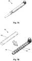
- FIG. 7Ais a schematic, perspective view of a connector assembly with a stiffening sleeve installed over the connector housing according to at least some embodiments of the present invention
- FIG. 7Bis a schematic, perspective, exploded view of a connector assembly of FIG. 7A ;
- FIG. 8is a schematic overview of one embodiment of components of a stimulation system, including an electronic subassembly disposed within a control module, according to the invention.
- the present inventionis directed to the area of implantable electrical stimulation systems and methods of making and using the systems.
- the present inventionis also directed implantable neuromodulation lead extensions and stiffened connector assemblies that may limit bending movement of components within the connector assemblies and mitigate against a misalignment or a decoupling of electrical connections within the connector assemblies, as well as methods of making and using the same.
- Suitable implantable electrical stimulation systemsinclude, but are not limited to, a least one lead with one or more electrodes disposed along a distal end of the lead and one or more terminals disposed along the one or more proximal ends of the lead.
- Leadsinclude, for example, percutaneous leads, paddle leads, and cuff leads. Examples of electrical stimulation systems with leads are found in, for example, U.S. Pat. Nos.
- connectors, connector contacts and connector assemblies for electrical stimulation systems with leadsare found in, for example, U.S. Pat. Nos. 8,849,396; 7,244,150; 8,600,507; 8,897,876; 8,682,439; U.S. Patent Applications Publication Nos. 2012/0053646; 2014/0148885; 2015/0209575; 2016/0059019; and U.S. Patent Provisional Patent Application Nos. 62/193,472; 62/216,594; 62/259,463; and 62/278,667, all of which are incorporated by reference in their entireties.
- FIG. 1illustrates schematically one embodiment of an electrical stimulation system 100 .
- the electrical stimulation systemincludes a control module (e.g., a stimulator or pulse generator) 102 and a lead 103 .
- the lead 103including a paddle body 104 and one or more lead bodies 106 coupling the control module 102 to the paddle body 104 .
- the paddle body 104 and the one or more lead bodies 106form the lead 103 .
- the paddle body 104typically includes a plurality of electrodes 134 that form an array of electrodes 133 .
- the control module 102typically includes an electronic subassembly 110 and an optional power source 120 disposed in a sealed housing 114 . In FIG. 1 , two lead bodies 106 are shown coupled to the control module 102 .
- the control module 102typically includes one or more connector assemblies 144 into which the proximal end of the one or more lead bodies 106 can be plugged to make an electrical connection via connector contacts (e.g., 316 in FIG. 3A ) disposed in the connector assembly 144 and terminals (e.g., 310 in FIG. 3A ) on each of the one or more lead bodies 106 .
- the connector contactsare coupled to the electronic subassembly 110 and the terminals are coupled to the electrodes 134 .
- FIG. 1two connector assemblies 144 are shown.
- the one or more connector assemblies 144may be disposed in a header 150 .
- the header 150provides a protective covering over the one or more connector assemblies 144 .
- the header 150may be formed using any suitable process including, for example, casting, molding (including injection molding), and the like.
- one or more lead extensions 324can be disposed between the one or more lead bodies 106 and the control module 102 to extend the distance between the one or more lead bodies 106 and the control module 102 .
- the electrical stimulation systemcan include more, fewer, or different components and can have a variety of different configurations including those configurations disclosed in the electrical stimulation system references cited herein.
- the electrodes 134can be disposed in an array at or near the distal end of a lead body 106 ′ forming a percutaneous lead 103 , as illustrated in FIG. 2 .
- the percutaneous leadmay be isodiametric along the length of the lead body 106 ′′.
- the lead body 106 ′can be coupled with a control module 102 ′ with a single connector assembly 144 .
- the electrical stimulation system or components of the electrical stimulation systemincluding one or more of the lead bodies 106 , the control module 102 , and, in the case of a paddle lead, the paddle body 104 , are typically implanted into the body of a patient.
- the electrical stimulation systemcan be used for a variety of applications including, but not limited to, spinal cord stimulation, brain stimulation, neural stimulation, muscle activation via stimulation of nerves innervating muscle, and the like.
- the electrodes 134can be formed using any conductive, biocompatible material. Examples of suitable materials include metals, alloys, conductive polymers, conductive carbon, and the like, as well as combinations thereof. In at least some embodiments, one or more of the electrodes 134 are formed from one or more of: platinum, platinum iridium, palladium, titanium, or rhenium.
- the number of electrodes 134 in the array of electrodes 133may vary. For example, there can be two, three, four, five, six, seven, eight, nine, ten, eleven, twelve, thirteen, fourteen, fifteen, sixteen, or more electrodes 134 . As will be recognized, other numbers of electrodes 134 may also be used. In FIG. 1 , sixteen electrodes 134 are shown.
- the electrodes 134can be formed in any suitable shape including, for example, round, oval, triangular, rectangular, pentagonal, hexagonal, heptagonal, octagonal, or the like.
- the electrodes of the paddle body 104 or one or more lead bodies 106are typically disposed in, or separated by, a non-conductive, biocompatible material including, for example, silicone, polyurethane, and the like or combinations thereof.
- the paddle body 104 and one or more lead bodies 106may be formed in the desired shape by any process including, for example, molding (including injection molding), casting, and the like. Electrodes and connecting wires can be disposed onto or within a paddle body either prior to or subsequent to a molding or casting process.
- the non-conductive materialtypically extends from the distal end of the lead 103 to the proximal end of each of the one or more lead bodies 106 .
- the non-conductive, biocompatible material of the paddle body 104 and the one or more lead bodies 106may be the same or different.
- the paddle body 104 and the one or more lead bodies 106may be a unitary structure or can be formed as two separate structures that are permanently or detachably coupled together.
- Terminalsare typically disposed at the proximal end of the one or more lead bodies 106 for connection to corresponding conductive contacts (e.g., 316 in FIG. 3A ) in connector assemblies (e.g., 144 in FIG. 1 ) disposed on, for example, the control module 102 (or to other devices, such as conductive contacts on a lead extension, an operating room cable, a splitter, an adaptor, or the like).
- Conductive wiresextend from the terminals (e.g., 310 in FIG. 3A ) to the electrodes 134 .
- one or more electrodes 134are electrically coupled to a terminal (e.g., 310 in FIG. 3A ).
- each terminale.g., 310 in FIG. 3A
- the conductive wiresmay be embedded in the non-conductive material of the lead or can be disposed in one or more lumens (not shown) extending along the lead. In some embodiments, there is an individual lumen for each conductive wire. In other embodiments, two or more conductive wires may extend through a lumen. There may also be one or more lumens (not shown) that open at, or near, the proximal end of the lead, for example, for inserting a stylet rod to facilitate placement of the lead within a body of a patient. Additionally, there may also be one or more lumens (not shown) that open at, or near, the distal end of the lead, for example, for infusion of drugs or medication into the site of implantation of the paddle body 104 . The one or more lumens may, optionally, be flushed continually, or on a regular basis, with saline, epidural fluid, or the like. The one or more lumens can be permanently or removably sealable at the distal end.
- the one or more lead bodies 106may be coupled to the one or more connector assemblies 144 disposed on the control module 102 .
- the control module 102can include any suitable number of connector assemblies 144 including, for example, two three, four, five, six, seven, eight, or more connector assemblies 144 . It will be understood that other numbers of connector assemblies 144 may be used instead.
- each of the two lead bodies 106includes eight terminals that are shown coupled with eight conductive contacts disposed in a different one of two different connector assemblies 144 .
- FIG. 3Ais a schematic side view of one embodiment of a plurality of connector assemblies 144 disposed on the control module 102 .
- the control module 102includes two connector assemblies 144 .
- the control module 102includes four connector assemblies 144 .
- proximal ends 306 of the plurality of lead bodies 106are shown configured for insertion to the control module 102 .
- FIG. 3Bis a schematic side view of one embodiment of a single connector assembly 144 disposed on the control module 102 ′. In FIG. 3B , the proximal end 306 of the single lead body 106 ′ is shown configured for insertion to the control module 102 ′.
- the one or more connector assemblies 144are disposed in the header 150 .
- the header 150defines one or more ports 304 into which the proximal end(s) 306 of the one or more lead bodies 106 / 106 ′ with terminals 310 can be inserted, as shown by directional arrows 312 , in order to gain access to the connector contacts disposed in the one or more connector assemblies 144 .
- the one or more connector assemblies 144each include a connector housing 314 and a plurality of connector contacts 316 disposed therein.
- the connector housing 314defines a port (not shown) that provides access to the plurality of connector contacts 316 .
- one or more of the connector assemblies 144further includes a retaining element 318 configured to fasten the corresponding lead body 106 / 106 ′ to the connector assembly 144 when the lead body 106 / 106 ′ is inserted into the connector assembly 144 to prevent undesired detachment of the lead body 106 / 106 ′ from the connector assembly 144 .
- the retaining element 318may include an aperture 320 through which a fastener (e.g., a set screw, pin, or the like) may be inserted and secured against an inserted lead body 106 / 106 ′.
- the connector contacts 316can be aligned with the terminals 310 disposed on the one or more lead bodies 106 / 106 ′ to electrically couple the control module 102 to the electrodes ( 134 of FIG. 1 ) disposed at a distal end of the one or more lead bodies 106 .
- Examples of connector assemblies in control modulesare found in, for example, U.S. Pat. Nos. 7,244,150 and 8,224,450, which are incorporated by reference.
- the electrical stimulation systemincludes one or more lead extensions.
- the one or more lead bodies 106 / 106 ′can be coupled to one or more lead extensions which, in turn, are coupled to the control module 102 / 102 ′.
- a lead extension connector assembly 322is disposed on a lead extension 324 .
- the lead extension connector assembly 322is shown disposed at a distal end 326 of the lead extension 324 .
- the lead extension connector assembly 322includes a contact housing 328 .
- the contact housing 328defines at least one port 330 into which a proximal end 306 of the lead body 106 ′ with terminals 310 can be inserted, as shown by directional arrow 338 .
- the lead extension connector assembly 322also includes a plurality of connector contacts 340 .
- the connector contacts 340 disposed in the contact housing 328can be aligned with the terminals 310 on the lead body 106 to electrically couple the lead extension 324 to the electrodes ( 134 of FIG. 1 ) disposed at a distal end (not shown) of the lead body 106 ′.
- the proximal end of a lead extensioncan be similarly configured as a proximal end of a lead body.
- the lead extension 324may include a plurality of conductive wires (not shown) that electrically couple the connector contacts 340 to terminal on a proximal end 348 of the lead extension 324 .
- the conductive wires disposed in the lead extension 324can be electrically coupled to a plurality of terminals (not shown) disposed on the proximal end 348 of the lead extension 324 .
- the proximal end 348 of the lead extension 324is configured for insertion into a lead extension connector assembly disposed in another lead extension.
- the proximal end 348 of the lead extension 324is configured for insertion into the connector assembly 144 disposed on the control module 102 ′.
- control modules 102 / 102 ′can receive either lead bodies 106 / 106 ′ or lead extensions 324 .
- electrical stimulation system 100can include a plurality of lead extensions 224 .
- each of the lead bodies 106 shown in FIGS. 1 and 3Acan, alternatively, be coupled to a different lead extension 224 which, in turn, are each coupled to different ports of a two-port control module, such as the control module 102 of FIGS. 1 and 3A .
- the connector assembly described belowmay be disposed in many different locations including, for example, on lead extensions (see e.g., 322 of FIG. 3C ), lead adapters, lead splitters, the connector portion of control modules (see e.g., 144 of FIGS. 1-3B ), or the like.
- the connector assembliesare disposed on the distal ends of lead extensions.
- Techniques of connecting, placing and anchoring of the connector assemblycan result in the bending and deformation of the connector assembly, which in turn may result in misalignment of the contacts and terminals. Also, bending, and thus misalignment, may occur after implantation, particularly with patient movement.
- a connector assemblycan permit a controlled amount of bending and may resist bending or limit bending.
- the connector assemblyincludes one or more inserts or stiffening elements that operate to resist or limit the amount of bending of the connector assembly in one or more directions.
- FIG. 4Ashows a schematic, perspective view of a connector assembly 400 having a connector housing 402 covering a plurality of connector contacts 404 that are separated by spacers 406 .
- Stiffening elements 408extend through the spacers 406 and will be described below in greater detail.
- the connector contacts 404may take the form of conductive spring contacts or any other suitable contact arrangement.
- FIG. 4Bshows a cross-sectional view of the connector assembly 400 of FIG. 4A in which the cross-section is taken near a septum 410 .
- the stiffening elements 408may advantageously limit an amount of bending deformation of the connector assembly 400 whether during implantation or over its operational life.
- FIGS. 4C and 4Dshows a schematic, close-up views of one of the spacers 406 , which optionally includes a recessed region 410 to receive the connector contact 404 ( FIG. 4A ).
- a center lumen 412extends through the spacer 406 .
- the spacer 406includes a plurality of apertures 414 for receiving the stiffening elements 408 ( FIG. 4A ).
- the apertures 414may run the full length of the connector assembly or just a partial length of the connector assembly.
- the stiffening elements 408may be as long as the apertures 414 or shorter than the apertures 414 .
- the stiffening elements 408extend between, and connect, at least two the spacers 406 and, in at least some embodiments, extend between, and connect, all of the spacers 406 of the connector assembly.
- the apertures 414 and stiffening elements 408are disposed radially outside an outer radius of the connector contacts (as illustrated, for example, in FIGS. 4A and 4B .)
- the apertures 414 and stiffening elements 408may be disposed in an outer region 415 of the spacer 406 that extends beyond the outer radius of the connector contacts and, at least in some embodiments, may be partially disposed over one or more connector contacts.
- the spacer 406may have a single aperture, two or three apertures, or more than four apertures.
- the apertures 414may be circumferentially equidistant from each other or may have a non-uniform circumferential spacing.
- the number of stiffening elements 408may be equal to the number of apertures 414 or less than the number of apertures 414 . Additionally or alternatively, some of the stiffening elements 408 may be stiffer or more rigid than other stiffening elements 408 .
- the connector contacts 404are electrically insulated from one another by the non-conductive spacers 406 .
- the spacers 406 and the connector housing 402may be made from a non-conductive, biocompatible material such as, for example, silicone, polyurethane, polyetheretherketone (“PEEK”), epoxy, and the like or combinations thereof.
- the spacers 408 and housing 402can be made of the same or different materials.
- the connector contacts 404can be formed using any conductive, biocompatible material. Examples of suitable materials include metals, alloys, conductive polymers, conductive carbon, and the like, as well as combinations thereof. In at least some embodiments, one or more of the contacts are formed from one or more of: platinum, platinum iridium, palladium, palladium rhodium, or titanium.
- the stiffening elements 408may be made from a metallic material, such as, but not limited to, the materials used for the contacts, or can be made from a rigid plastic or reinforced composite material. In at least some embodiments, the material of the stiffening elements 408 is stiffer than the material of the connector housing 402 . In at least some embodiments, the material of the stiffening elements 408 is stiffer than the material of the spacers 406 .
- FIG. 5shows a schematic, perspective view of a portion of a connector assembly 500 having a connector housing (not shown for purposes of clarity), connector contacts 504 , spacers 506 (only two of which are illustrated for purposes of clarify), and one or more non-conductive inserts 508 that operate as bending limiters as explained below.
- the inserts 508are arranged along one side of the connector assembly 500 to provide for controlled or allowable bending of the connector assembly 500 .
- the inserts 508operate as mechanical stops to limit the amount of flexion or distortion of the connector assembly 500 when a bending force is applied in a direction that compresses the insert and adjacent connector contacts 504 .
- reducing or limiting the amount of bending distortion of the connector assemblymay advantageously reduce any misalignment due to bending and thereby improve the electrical communication between the conductive components of the connector assembly, the lead, the lead extension or any other component or device coupled to or received by the connector assembly.
- the connector contacts 504are axially or longitudinally spaced-apart and disposed along a lumen 510 such that the connector contacts 504 are each exposed to the lumen 510 .
- the connector contacts 504are configured for coupling to a proximal end of a lead or lead extension when the proximal end of the lead or lead extension is inserted into the lumen 510 .
- the connector contacts 504are separated by the spacers 506 , which are disposed within the spaces provided between adjacent connector contacts 504 .
- the spacers 506are similar to spacers 406 with or without the apertures 414 .
- At least one of the spacers 506includes a first region 512 , which is the region associated with the respective insert 508 .
- a bending force 514 applied to the connector assembly 500places the first region 512 of the spacer 506 in a compressive state or under a compressive stress. Due to the relative softness and flexibility of the spacers 506 , the first region 512 deforms or compresses when under the compressive stress. This compressive deformation, in turn, causes the adjacent connector contacts 504 a , 504 b to move closer to each other.
- the non-conductive insert 508is disposed on or within the first region 512 of the spacer 506 .
- the non-conductive insert 508has a length that maintains at least a minimum distance between the adjacent connector contacts 504 a , 504 b when the first region 512 is placed under compressive stress.
- the inserts 508are made from a non-conductive material that is more rigid than the spacer material.
- the inserts 508may be made from a rigid plastic material.
- the inserts 508may take a variety of shapes and configurations. In the illustrated embodiment, the inserts 508 have an elliptical form, but could be rectangular or some other shape.
- the connector assembly 500may be bent in a variety of directions.
- the inserts 508are longitudinally aligned along one side of the connector assembly to reduce or limit the bending in a plane defined by the aligned inserts 508 (e.g., see schematic bending representation 514 ).
- the number of inserts 508 and their locationsmay vary depending on an anticipated bending force, weight, size and other factors.
- each spacer 506may not have an insert disposed on or within it, but instead every other spacer 506 has an insert disposed on or within it.
- the spacer 506has a recess where the insert 508 resides.
- the spacer 506may have an open interior space within which the insert 508 resides and can move.
- the spacer 506partially or fully surrounds the insert 508 .
- the connector contacts 504can optionally include recesses 516 for receiving the inserts 508 and for limiting the distance that the connector contacts 504 can move when the in-plane bending force 514 is applied to the connector assembly 500 .
- the length of the recesses 516provides the limiting factor for how far the connector contacts 504 can move toward each other when the connector assembly 500 is bent.
- the recesses 516may extend all the way through the wall thickness of the connector contacts 504 or partially through.
- the recesses 516have a shape that is complementary to the shape of an end portion of the inserts 508 . Referring to the illustrated embodiment, the recesses 516 take the form of half-circular shaped cutouts to receive the elliptically shaped inserts 508 . However, it is appreciated that the recesses 516 may take other shapes preferably consistent with the shapes of the inserts 508 .
- FIG. 6shows a schematic, perspective view of another connector assembly 600 having a connector housing (not shown for purposes of clarity), connector contacts 604 , spacers 606 , and one or more non-conductive inserts 608 that operate as bending limiters.
- the illustrated connector assembly 600is structurally and functionally similar to the connector assembly 500 described above except that the inserts 608 are provided on at least two sides (e.g., opposing sides) of the connector assembly 600 to limit bi-directional, in-plane bending as schematically represented by bending plane 620 .
- another set or sets of insertscould be provided on other quadrants of the connector assembly 600 to limit bending in a direction that is non-parallel to the bending plane 620 .
- the number of inserts or the number of sets of insertsmay be 1, 2, 3, 4 or more.
- the sets of insertsmay be circumferentially equidistant from each other or may be spaced in a non-uniform circumferential manner. For example, there may be four sets of inserts that are arranged at 90 degree intervals around the circumference of the connector assembly.
- FIGS. 7A and 7Bshow schematic, perspective views of a connector assembly 700 having a connector housing 702 covering a plurality of connector contacts 704 that are separated by spacers 706 .
- a stiffening sleeve 708such as a cylinder or tube, is placed over the connector contacts 704 and spacers 706 and within the connector housing 702 .
- the stiffening sleeve 708may take the form of a mesh sleeve that increases the stiffness of the overall connector assembly 700 .
- the stiffening sleevemay be a solid sleeve.
- the stiffening sleeve 708may be made from a rigid material such as a metal or a plastic.
- the stiffening sleeve 708is made from a fluorinated ethylene propylene (FEP) material that is installed on the connector housing 702 through a heat shrinking process.
- FEPfluorinated ethylene propylene
- the stiffening sleeve 708may be installed within the connector housing 702 by a variety of techniques such as, but not limited to, interference fitting, bonding, or press fitting. Additionally or alternatively, the increase of overall bending stiffness provided by the addition of the stiffening sleeve 708 is dependent on a variety of factors that include, but are not limited to, the design of the sleeve (e.g., thickness, length, etc.), the material of the sleeve (e.g., metal or plastic), and the construction of the sleeve (e.g., a tightly wound mesh sleeve as compared to a loosely wound mesh sleeve).
- the design of the sleevee.g., thickness, length, etc.
- the material of the sleevee.g., metal or plastic
- the construction of the sleevee.g., a tightly wound mesh sleeve as compared to a loosely wound mesh
- FIG. 8is a schematic overview of one embodiment of components of an electrical stimulation system 800 including an electronic subassembly 810 disposed within a control module. It will be understood that the electrical stimulation system can include more, fewer, or different components and can have a variety of different configurations including those configurations disclosed in the stimulator references cited herein.
- a power source 812can be used including, for example, a battery such as a primary battery or a rechargeable battery.
- a batterysuch as a primary battery or a rechargeable battery.
- other power sourcesinclude super capacitors, nuclear or atomic batteries, mechanical resonators, infrared collectors, thermally-powered energy sources, flexural powered energy sources, bioenergy power sources, fuel cells, bioelectric cells, osmotic pressure pumps, and the like including the power sources described in U.S. Pat. No. 7,437,193, incorporated herein by reference.
- powercan be supplied by an external power source through inductive coupling via the optional antenna 818 or a secondary antenna.
- the external power sourcecan be in a device that is mounted on the skin of the user or in a unit that is provided near the user on a permanent or periodic basis.
- the batterymay be recharged using the optional antenna 818 , if desired. Power can be provided to the battery for recharging by inductively coupling the battery through the antenna to a recharging unit 816 external to the user. Examples of such arrangements can be found in the references identified above.
- electrical currentis emitted by the electrodes 134 on the paddle or lead body to stimulate nerve fibers, muscle fibers, or other body tissues near the electrical stimulation system.
- the processor 804is generally included to control the timing and electrical characteristics of the electrical stimulation system. For example, the processor 804 can, if desired, control one or more of the timing, frequency, strength, duration, and waveform of the pulses. In addition, the processor 804 can select which electrodes can be used to provide stimulation, if desired. In some embodiments, the processor 804 selects which electrode(s) are cathodes and which electrode(s) are anodes. In some embodiments, the processor 804 is used to identify which electrodes provide the most useful stimulation of the desired tissue.
- Any processorcan be used and can be as simple as an electronic device that, for example, produces pulses at a regular interval or the processor can be capable of receiving and interpreting instructions from an external programming unit 808 that, for example, allows modification of pulse characteristics.
- the processor 804is coupled to a receiver 802 which, in turn, is coupled to the optional antenna 818 . This allows the processor 804 to receive instructions from an external source to, for example, direct the pulse characteristics and the selection of electrodes, if desired.
- the antenna 818is capable of receiving signals (e.g., RF signals) from an external telemetry unit 806 which is programmed by the programming unit 808 .
- the programming unit 808can be external to, or part of, the telemetry unit 806 .
- the telemetry unit 806can be a device that is worn on the skin of the user or can be carried by the user and can have a form similar to a pager, cellular phone, or remote control, if desired.
- the telemetry unit 806may not be worn or carried by the user but may only be available at a home station or at a clinician's office.
- the programming unit 808can be any unit that can provide information to the telemetry unit 806 for transmission to the electrical stimulation system 800 .
- the programming unit 808can be part of the telemetry unit 806 or can provide signals or information to the telemetry unit 806 via a wireless or wired connection.
- One example of a suitable programming unitis a computer operated by the user or clinician to send signals to the telemetry unit 806 .
- the signals sent to the processor 804 via the antenna 818 and the receiver 802can be used to modify or otherwise direct the operation of the electrical stimulation system.
- the signalsmay be used to modify the pulses of the electrical stimulation system such as modifying one or more of pulse duration, pulse frequency, pulse waveform, and pulse strength.
- the signalsmay also direct the electrical stimulation system 800 to cease operation, to start operation, to start charging the battery, or to stop charging the battery.
- the stimulation systemdoes not include the antenna 818 or receiver 802 and the processor 804 operates as programmed.
- the electrical stimulation system 800may include a transmitter (not shown) coupled to the processor 804 and the antenna 818 for transmitting signals back to the telemetry unit 806 or another unit capable of receiving the signals.
- the electrical stimulation system 800may transmit signals indicating whether the electrical stimulation system 800 is operating properly or not or indicating when the battery needs to be charged or the level of charge remaining in the battery.
- the processor 804may also be capable of transmitting information about the pulse characteristics so that a user or clinician can determine or verify the characteristics.
Landscapes
- Health & Medical Sciences (AREA)
- Animal Behavior & Ethology (AREA)
- Veterinary Medicine (AREA)
- Engineering & Computer Science (AREA)
- Biomedical Technology (AREA)
- Nuclear Medicine, Radiotherapy & Molecular Imaging (AREA)
- Radiology & Medical Imaging (AREA)
- Public Health (AREA)
- General Health & Medical Sciences (AREA)
- Life Sciences & Earth Sciences (AREA)
- Neurology (AREA)
- Neurosurgery (AREA)
- Heart & Thoracic Surgery (AREA)
- Cardiology (AREA)
- Orthopedic Medicine & Surgery (AREA)
- Electrotherapy Devices (AREA)
Abstract
Description
Claims (20)
Priority Applications (1)
| Application Number | Priority Date | Filing Date | Title |
|---|---|---|---|
| US15/715,974US10543374B2 (en) | 2016-09-30 | 2017-09-26 | Connector assemblies with bending limiters for electrical stimulation systems and methods of making and using same |
Applications Claiming Priority (2)
| Application Number | Priority Date | Filing Date | Title |
|---|---|---|---|
| US201662402715P | 2016-09-30 | 2016-09-30 | |
| US15/715,974US10543374B2 (en) | 2016-09-30 | 2017-09-26 | Connector assemblies with bending limiters for electrical stimulation systems and methods of making and using same |
Publications (2)
| Publication Number | Publication Date |
|---|---|
| US20180093098A1 US20180093098A1 (en) | 2018-04-05 |
| US10543374B2true US10543374B2 (en) | 2020-01-28 |
Family
ID=61757566
Family Applications (1)
| Application Number | Title | Priority Date | Filing Date |
|---|---|---|---|
| US15/715,974Active2037-11-08US10543374B2 (en) | 2016-09-30 | 2017-09-26 | Connector assemblies with bending limiters for electrical stimulation systems and methods of making and using same |
Country Status (1)
| Country | Link |
|---|---|
| US (1) | US10543374B2 (en) |
Cited By (1)
| Publication number | Priority date | Publication date | Assignee | Title |
|---|---|---|---|---|
| US20220368055A1 (en)* | 2019-10-01 | 2022-11-17 | Verily Life Sciences Llc | Separable High Density Connectors For Implantable Device |
Families Citing this family (14)
| Publication number | Priority date | Publication date | Assignee | Title |
|---|---|---|---|---|
| US10342983B2 (en) | 2016-01-14 | 2019-07-09 | Boston Scientific Neuromodulation Corporation | Systems and methods for making and using connector contact arrays for electrical stimulation systems |
| US10543374B2 (en) | 2016-09-30 | 2020-01-28 | Boston Scientific Neuromodulation Corporation | Connector assemblies with bending limiters for electrical stimulation systems and methods of making and using same |
| US10905871B2 (en) | 2017-01-27 | 2021-02-02 | Boston Scientific Neuromodulation Corporation | Lead assemblies with arrangements to confirm alignment between terminals and contacts |
| US10814136B2 (en) | 2017-02-28 | 2020-10-27 | Boston Scientific Neuromodulation Corporation | Toolless connector for latching stimulation leads and methods of making and using |
| US10603499B2 (en) | 2017-04-07 | 2020-03-31 | Boston Scientific Neuromodulation Corporation | Tapered implantable lead and connector interface and methods of making and using |
| WO2019023067A1 (en) | 2017-07-25 | 2019-01-31 | Boston Scientific Neuromodulation Corporation | Systems and methods for making and using an enhanced connector of an electrical stimulation system |
| US11045656B2 (en) | 2017-09-15 | 2021-06-29 | Boston Scientific Neuromodulation Corporation | Biased lead connector for operating room cable assembly and methods of making and using |
| US10639485B2 (en) | 2017-09-15 | 2020-05-05 | Boston Scientific Neuromodulation Corporation | Actuatable lead connector for an operating room cable assembly and methods of making and using |
| US11139603B2 (en) | 2017-10-03 | 2021-10-05 | Boston Scientific Neuromodulation Corporation | Connectors with spring contacts for electrical stimulation systems and methods of making and using same |
| US11103712B2 (en) | 2018-01-16 | 2021-08-31 | Boston Scientific Neuromodulation Corporation | Connector assemblies with novel spacers for electrical stimulation systems and methods of making and using same |
| US11052259B2 (en) | 2018-05-11 | 2021-07-06 | Boston Scientific Neuromodulation Corporation | Connector assembly for an electrical stimulation system and methods of making and using |
| EP3946569B1 (en) | 2019-04-01 | 2023-11-15 | Boston Scientific Neuromodulation Corporation | Low-profile control module for an electrical stimulation system |
| US11357992B2 (en) | 2019-05-03 | 2022-06-14 | Boston Scientific Neuromodulation Corporation | Connector assembly for an electrical stimulation system and methods of making and using |
| US12343547B2 (en) | 2021-08-19 | 2025-07-01 | Boston Scientific Neuromodulation Corporation | Connectors for an electrical stimulation system and methods of making and using |
Citations (416)
| Publication number | Priority date | Publication date | Assignee | Title |
|---|---|---|---|---|
| US3222471A (en) | 1963-06-10 | 1965-12-07 | Ripley Company Inc | Multiple electrical connector with longitudinal spaced contacts carried by insulating key |
| US3601747A (en) | 1969-09-18 | 1971-08-24 | Singer General Precision | Brush block retractor and alignment device |
| US3718142A (en) | 1971-04-23 | 1973-02-27 | Medtronic Inc | Electrically shielded, gas-permeable implantable electro-medical apparatus |
| US3757789A (en) | 1971-10-26 | 1973-09-11 | I Shanker | Electromedical stimulator lead connector |
| US3771106A (en) | 1971-04-14 | 1973-11-06 | New Nippon Electric Co | Socket suited for revolving the lamp attached thereto |
| US3908668A (en) | 1974-04-26 | 1975-09-30 | Medtronic Inc | Tissue stimulator with sealed lead connector |
| US3951154A (en) | 1974-04-30 | 1976-04-20 | Medtronic, Inc. | Lead connector for electro-medical device |
| US3990727A (en) | 1976-01-26 | 1976-11-09 | Stephen Franics Gallagher | Quick detachable coupler |
| US4003616A (en) | 1975-12-03 | 1977-01-18 | Clairol Incorporated | Swivelling electrical connector |
| US4112953A (en) | 1977-03-11 | 1978-09-12 | Medcor, Inc. | Pacer stimulator with improved lead connector |
| US4142532A (en) | 1978-04-07 | 1979-03-06 | Medtronic, Inc. | Body implantable stimulator with novel connector and method |
| US4180078A (en) | 1978-04-07 | 1979-12-25 | Medtronic, Inc. | Lead connector for a body implantable stimulator |
| US4245642A (en) | 1979-06-28 | 1981-01-20 | Medtronic, Inc. | Lead connector |
| US4259962A (en) | 1979-08-24 | 1981-04-07 | Cordis Corporation | Sealing system for cardiac pacer lead connector |
| US4310001A (en) | 1980-04-21 | 1982-01-12 | Medtronic, Inc. | Connector assembly for body implantable medical systems |
| US4364625A (en) | 1980-06-12 | 1982-12-21 | Bell Telephone Laboratories, Incorporated | Electrical jack assembly |
| US4367907A (en) | 1980-08-04 | 1983-01-11 | Magnetic Controls Company | Circuit monitoring jack |
| US4411276A (en) | 1981-04-28 | 1983-10-25 | Medtronic, Inc. | Implantable multiple connector |
| US4411277A (en) | 1981-04-28 | 1983-10-25 | Medtronic, Inc. | Implantable connector |
| US4461194A (en) | 1982-04-28 | 1984-07-24 | Cardio-Pace Medical, Inc. | Tool for sealing and attaching a lead to a body implantable device |
| US4466441A (en) | 1982-08-02 | 1984-08-21 | Medtronic, Inc. | In-line and bifurcated cardiac pacing lead connector |
| US4516820A (en) | 1983-01-27 | 1985-05-14 | The Commonwealth Of Australia | Cochlear prosthesis package connector |
| US4540236A (en) | 1983-07-18 | 1985-09-10 | Cordis Corporation | Quick lock/quick release connector |
| USRE31990E (en) | 1978-11-22 | 1985-09-24 | Intermedics, Inc. | Multiple function lead assembly and method for inserting assembly into an implantable tissue stimulator |
| US4602624A (en) | 1984-10-11 | 1986-07-29 | Case Western Reserve University | Implantable cuff, method of manufacture, and method of installation |
| US4603696A (en) | 1985-02-14 | 1986-08-05 | Medtronic, Inc. | Lead connector |
| US4614395A (en) | 1985-04-04 | 1986-09-30 | Cordis Corporation | Quick connector to medical electrical lead |
| US4630611A (en) | 1981-02-02 | 1986-12-23 | Medtronic, Inc. | Orthogonally-sensing lead |
| US4695117A (en) | 1985-06-03 | 1987-09-22 | Switchcraft, Inc. | Jack module and jackfield |
| US4695116A (en) | 1984-02-27 | 1987-09-22 | Switchcraft, Inc. | Stacked electrical jacks |
| US4712557A (en) | 1986-04-28 | 1987-12-15 | Cordis Leads, Inc. | A pacer including a multiple connector assembly with removable wedge and method of use |
| US4715380A (en) | 1986-04-03 | 1987-12-29 | Telectronics N.V. | Capped pacer neck containing a connector assembly |
| US4744370A (en) | 1987-04-27 | 1988-05-17 | Cordis Leads, Inc. | Lead assembly with selectable electrode connection |
| US4784141A (en) | 1987-08-04 | 1988-11-15 | Cordis Leads, Inc. | Lead locking mechanism for cardiac pacers |
| US4832032A (en) | 1985-08-16 | 1989-05-23 | La Jolla Technology, Inc. | Electrical apparatus protective interconnect |
| US4840580A (en) | 1987-06-05 | 1989-06-20 | Siemens Ag | Connector arrangement for a lead for an implantable stimulation device |
| US4850359A (en) | 1987-10-16 | 1989-07-25 | Ad-Tech Medical Instrument Corporation | Electrical brain-contact devices |
| US4860750A (en) | 1986-04-17 | 1989-08-29 | Intermedics Inc. | Sidelock pacer lead connector |
| US4867708A (en) | 1986-12-27 | 1989-09-19 | Iizuka Electric Industry Company Limited | Electric jack |
| US4869255A (en) | 1987-12-04 | 1989-09-26 | Ad-Tech Medical Instrument Corp. | Electrical connection device |
| US4898173A (en) | 1988-04-22 | 1990-02-06 | Medtronic, Inc. | In-line pacemaker connector system |
| US4899753A (en) | 1985-10-02 | 1990-02-13 | Fukuda Denshi Co., Ltd. | Electrocardiographic electrode |
| US4951687A (en) | 1989-01-31 | 1990-08-28 | Medtronic, Inc. | Medical electrical lead connector |
| US4995389A (en) | 1985-12-16 | 1991-02-26 | Telectronics Pacing Systems, Inc. | Multielectrode quick connect cardiac pacing lead connector assembly |
| US5000194A (en) | 1988-08-25 | 1991-03-19 | Cochlear Corporation | Array of bipolar electrodes |
| US5000177A (en) | 1990-01-29 | 1991-03-19 | Cardiac Pacemakers, Inc. | Bipolar lead adapter with resilient housing and rigid retainers for plug seals |
| US5007864A (en) | 1989-11-27 | 1991-04-16 | Siemens-Pacesetter, Inc. | Device for adapting a pacemaker lead to a pacemaker |
| US5007435A (en) | 1988-05-25 | 1991-04-16 | Medtronic, Inc. | Connector for multiconductor pacing leads |
| US5070605A (en) | 1988-04-22 | 1991-12-10 | Medtronic, Inc. | Method for making an in-line pacemaker connector system |
| US5082453A (en) | 1991-05-16 | 1992-01-21 | Siemens-Pacesetter, Inc. | Multi-contact connector system for an implantable medical device |
| US5086773A (en) | 1990-09-10 | 1992-02-11 | Cardiac Pacemakers, Inc. | Tool-less pacemaker lead assembly |
| US5135001A (en) | 1990-12-05 | 1992-08-04 | C. R. Bard, Inc. | Ultrasound sheath for medical diagnostic instruments |
| US5193539A (en) | 1991-12-18 | 1993-03-16 | Alfred E. Mann Foundation For Scientific Research | Implantable microstimulator |
| US5193540A (en) | 1991-12-18 | 1993-03-16 | Alfred E. Mann Foundation For Scientific Research | Structure and method of manufacture of an implantable microstimulator |
| US5201865A (en) | 1991-10-28 | 1993-04-13 | Medtronic, Inc. | Medical lead impedance measurement system |
| US5241957A (en) | 1991-11-18 | 1993-09-07 | Medtronic, Inc. | Bipolar temporary pacing lead and connector and permanent bipolar nerve wire |
| US5252090A (en) | 1992-09-30 | 1993-10-12 | Telectronics Pacing Systems, Inc. | Self-locking implantable stimulating lead connector |
| US5261395A (en) | 1992-03-02 | 1993-11-16 | Cardiac Pacemaker, Inc. | Tooless pulse generator to lead connection |
| EP0580928A1 (en) | 1992-07-31 | 1994-02-02 | ARIES S.r.l. | A spinal electrode catheter |
| US5312439A (en) | 1991-12-12 | 1994-05-17 | Loeb Gerald E | Implantable device having an electrolytic storage electrode |
| US5324312A (en) | 1992-05-06 | 1994-06-28 | Medtronic, Inc. | Tool-less threaded connector assembly |
| US5330521A (en) | 1992-06-29 | 1994-07-19 | Cohen Donald M | Low resistance implantable electrical leads |
| US5336246A (en) | 1993-06-23 | 1994-08-09 | Telectronics Pacing Systems, Inc. | Lead connector assembly for medical device and method of assembly |
| US5348481A (en) | 1993-09-29 | 1994-09-20 | Cardiometrics, Inc. | Rotary connector for use with small diameter flexible elongate member having electrical capabilities |
| US5354326A (en) | 1993-01-27 | 1994-10-11 | Medtronic, Inc. | Screening cable connector for interface to implanted lead |
| US5358514A (en) | 1991-12-18 | 1994-10-25 | Alfred E. Mann Foundation For Scientific Research | Implantable microdevice with self-attaching electrodes |
| US5368496A (en) | 1993-12-10 | 1994-11-29 | Tetrad Corporation | Connector assembly having control lever actuation |
| US5374279A (en) | 1992-10-30 | 1994-12-20 | Medtronic, Inc. | Switchable connector block for implantable defibrillator |
| US5383913A (en) | 1993-04-21 | 1995-01-24 | Schiff; Steven M. | Bidirectional lead connector for left or right sided implantation of pacemakers and/or other implantable electrophysiologic devices and a method for using the same |
| US5413595A (en) | 1993-10-15 | 1995-05-09 | Pacesetter, Inc. | Lead retention and seal for implantable medical device |
| US5435731A (en) | 1994-05-12 | 1995-07-25 | Kang; Steve | Rotatable hidden connector for telephone transmitter |
| US5458629A (en) | 1994-02-18 | 1995-10-17 | Medtronic, Inc. | Implantable lead ring electrode and method of making |
| US5486202A (en) | 1993-12-17 | 1996-01-23 | Intermedics, Inc. | Cardiac stimulator lead connector |
| US5489225A (en) | 1993-12-16 | 1996-02-06 | Ventritex, Inc. | Electrical terminal with a collet grip for a defibrillator |
| US5509928A (en) | 1995-03-02 | 1996-04-23 | Pacesetter, Inc. | Internally supported self-sealing septum |
| US5522874A (en) | 1994-07-28 | 1996-06-04 | Gates; James T. | Medical lead having segmented electrode |
| US5534019A (en) | 1994-12-09 | 1996-07-09 | Ventritex, Inc. | Cardiac defibrillator with case that can be electrically active or inactive |
| US5545138A (en) | 1994-02-28 | 1996-08-13 | Medtronic, Inc. | Adjustable stiffness dilatation catheter |
| US5545189A (en) | 1995-11-02 | 1996-08-13 | Ventritex, Inc. | Case-activating switch assembly for an implantable cardiac stimulation device |
| US5560358A (en) | 1994-09-08 | 1996-10-01 | Radionics, Inc. | Connector design for multi-contact medical electrode |
| US5582180A (en) | 1994-11-04 | 1996-12-10 | Physio-Control Corporation | Combination three-twelve lead electrocardiogram cable |
| WO1997032628A1 (en) | 1996-03-07 | 1997-09-12 | Axon Engineering, Inc. | Polymer-metal foil structure for neural stimulating electrodes |
| US5679026A (en) | 1995-12-21 | 1997-10-21 | Ventritex, Inc. | Header adapter for an implantable cardiac stimulation device |
| US5683433A (en) | 1995-05-17 | 1997-11-04 | Ventritex, Inc. | Implantable medical apparatus with magnifying header |
| US5711316A (en) | 1996-04-30 | 1998-01-27 | Medtronic, Inc. | Method of treating movement disorders by brain infusion |
| US5713922A (en) | 1996-04-25 | 1998-02-03 | Medtronic, Inc. | Techniques for adjusting the locus of excitation of neural tissue in the spinal cord or brain |
| US5720631A (en) | 1995-12-07 | 1998-02-24 | Pacesetter, Inc. | Lead lumen sealing device |
| US5730628A (en) | 1996-09-25 | 1998-03-24 | Pacesetter, Inc. | Multi-contact connector for an implantable medical device |
| US5755743A (en) | 1996-06-05 | 1998-05-26 | Implex Gmbh Spezialhorgerate | Implantable unit |
| US5766042A (en) | 1995-12-28 | 1998-06-16 | Medtronic, Inc. | Tool-less locking and sealing assembly for implantable medical device |
| US5782892A (en) | 1997-04-25 | 1998-07-21 | Medtronic, Inc. | Medical lead adaptor for external medical device |
| EP0650694B1 (en) | 1993-11-01 | 1998-07-29 | Polartechnics Ltd | Apparatus for diseased tissue type recognition |
| US5796044A (en) | 1997-02-10 | 1998-08-18 | Medtronic, Inc. | Coiled wire conductor insulation for biomedical lead |
| US5800495A (en) | 1997-03-27 | 1998-09-01 | Sulzer Intermedics Inc. | Endocardial lead assembly |
| US5807144A (en) | 1996-01-29 | 1998-09-15 | Pacesetter Ab | Device for affixing a lead connector to an implantable stimulator |
| US5837006A (en) | 1996-09-10 | 1998-11-17 | Medtronic, Inc. | Retraction stop for helical medical lead electrode |
| US5843141A (en) | 1997-04-25 | 1998-12-01 | Medronic, Inc. | Medical lead connector system |
| US5843143A (en) | 1992-10-23 | 1998-12-01 | Cancer Research Campaign Technology Ltd. | Light source |
| US5906634A (en) | 1997-08-08 | 1999-05-25 | Cardiac Pacemakers, Inc. | Implantable device having a quick connect mechanism for leads |
| US5931861A (en) | 1997-04-25 | 1999-08-03 | Medtronic, Inc. | Medical lead adaptor having rotatable locking clip mechanism |
| US5938688A (en) | 1997-10-22 | 1999-08-17 | Cornell Research Foundation, Inc. | Deep brain stimulation method |
| US5951595A (en) | 1996-05-13 | 1999-09-14 | Pacesetteer, Inc. | Setscrewless connector assembly for implantable medical devices |
| US5957968A (en)* | 1997-09-26 | 1999-09-28 | Medtronic, Inc. | Suture sleeve with lead locking device |
| US5968082A (en) | 1996-03-04 | 1999-10-19 | Biotronik Mess- Und Therapiegeraete Gmbh & Co. Ingenieurbuero Berlin | Pacemaker lead locking mechanism |
| WO1999055411A2 (en) | 1998-04-30 | 1999-11-04 | Medtronic, Inc. | Apparatus and method for expanding a stimulation lead body in situ |
| US5989077A (en) | 1998-03-13 | 1999-11-23 | Intermedics Inc | Connector for implantable medical device |
| US6006135A (en) | 1997-09-26 | 1999-12-21 | Medtronic, Inc. | Apparatus for interconnecting implantable electrical leads and medical device |
| US6018684A (en) | 1998-07-30 | 2000-01-25 | Cardiac Pacemakers, Inc. | Slotted pacing/shocking electrode |
| US6042432A (en) | 1997-08-11 | 2000-03-28 | Yazaki Corporation | Terminal for charging with large current |
| US6051017A (en) | 1996-02-20 | 2000-04-18 | Advanced Bionics Corporation | Implantable microstimulator and systems employing the same |
| US6080188A (en) | 1997-06-16 | 2000-06-27 | Medtronic, Inc. | Setscrew less lead connector system for medical devices |
| WO2000038574A1 (en) | 1998-12-23 | 2000-07-06 | Nuvasive, Inc. | Nerve surveillance cannulae systems |
| US6112121A (en) | 1998-09-09 | 2000-08-29 | Intermedics Inc. | Implantable medical device with positive indication of lead connection and connector therefor |
| US6112120A (en) | 1997-07-03 | 2000-08-29 | Ela Medical S.A. | Apparatus for connecting a probe connector and an active implantable medical device |
| US6125302A (en) | 1997-09-02 | 2000-09-26 | Advanced Bionics Corporation | Precurved modiolar-hugging cochlear electrode |
| US6134478A (en) | 1998-06-05 | 2000-10-17 | Intermedics Inc. | Method for making cardiac leads with zone insulated electrodes |
| US6154678A (en) | 1999-03-19 | 2000-11-28 | Advanced Neuromodulation Systems, Inc. | Stimulation lead connector |
| US6162101A (en) | 1998-09-03 | 2000-12-19 | Pmt Corporation | Connector assembly for electrodes |
| US6167311A (en) | 1999-06-14 | 2000-12-26 | Electro Core Techniques, Llc | Method of treating psychological disorders by brain stimulation within the thalamus |
| US6164284A (en) | 1997-02-26 | 2000-12-26 | Schulman; Joseph H. | System of implantable devices for monitoring and/or affecting body parameters |
| US6167314A (en) | 1998-04-14 | 2000-12-26 | Intermedics Inc. | Cardiac pacemaker lead with pacemaker connector |
| US6175710B1 (en) | 1991-07-06 | 2001-01-16 | Fujitsu Limited | Electrophotographic recording apparatus using developing device with one-component type developer and having combination of charge injection effect and conductive contact type charger |
| US6181969B1 (en) | 1998-06-26 | 2001-01-30 | Advanced Bionics Corporation | Programmable current output stimulus stage for implantable device |
| US6185452B1 (en) | 1997-02-26 | 2001-02-06 | Joseph H. Schulman | Battery-powered patient implantable device |
| US6198969B1 (en) | 1998-02-12 | 2001-03-06 | Advanced Bionics Corporation | Implantable connector for multi-output neurostimulators |
| US6208894B1 (en) | 1997-02-26 | 2001-03-27 | Alfred E. Mann Foundation For Scientific Research And Advanced Bionics | System of implantable devices for monitoring and/or affecting body parameters |
| US6224450B1 (en) | 1998-08-28 | 2001-05-01 | Laurie J. Norton | Cycling activity belt |
| US6271094B1 (en) | 2000-02-14 | 2001-08-07 | International Business Machines Corporation | Method of making MOSFET with high dielectric constant gate insulator and minimum overlap capacitance |
| WO2001058520A1 (en) | 2000-02-09 | 2001-08-16 | Transneuronix, Inc. | Medical implant device for electrostimulation using discrete micro-electrodes |
| US20010023368A1 (en) | 1999-04-26 | 2001-09-20 | Advanced Neuromodulation Systems, Inc. | Implantable lead and method of manufacture |
| US6295944B1 (en) | 2000-06-20 | 2001-10-02 | J Timothy Lovett | Automatic tethering system for a floating dock |
| US6319021B1 (en) | 2000-12-19 | 2001-11-20 | Hon Hai Precision Ind. Co., Ltd. | Power connector providing improved performance |
| US6321126B1 (en) | 1998-12-07 | 2001-11-20 | Advanced Bionics Corporation | Implantable connector |
| US6322559B1 (en) | 1998-07-06 | 2001-11-27 | Vnus Medical Technologies, Inc. | Electrode catheter having coil structure |
| US6364278B1 (en) | 1999-11-05 | 2002-04-02 | Hon Hai Precision Ind. Co., Ltd. | Stand for supporting a computer |
| US6370434B1 (en) | 2000-02-28 | 2002-04-09 | Cardiac Pacemakers, Inc. | Cardiac lead and method for lead implantation |
| US6391985B1 (en) | 1999-10-21 | 2002-05-21 | Union Carbide Chemicals & Plastics Technology Corporation | High condensing mode polyolefin production under turbulent conditions in a fluidized bed |
| US6397108B1 (en) | 2000-04-03 | 2002-05-28 | Medtronic Inc. | Safety adaptor for temporary medical leads |
| US6415168B1 (en) | 2000-04-19 | 2002-07-02 | Ad-Tech Medical Instrument Corporation | Electrical connector for multi-contact medical electrodes |
| US6428336B1 (en) | 1997-03-25 | 2002-08-06 | Radi Medical Systems Ab | Female connector |
| US6428368B1 (en) | 2001-03-26 | 2002-08-06 | Pacesetter, Inc. | Side actuated lead connector assembly for implantable tissue stimulation device |
| US6430442B1 (en) | 2000-02-29 | 2002-08-06 | Medtronic, Inc. | Split contact with super elastic retaining ring for implantable medical device |
| WO2002068042A1 (en) | 2001-02-28 | 2002-09-06 | Gill Steven Streatfield | Brain electrode |
| US20020143376A1 (en) | 2000-05-05 | 2002-10-03 | Chinn Kenny K. | Multiple in-line contact connector |
| US6466824B1 (en) | 2001-04-23 | 2002-10-15 | Medtronic, Inc. | Bi-atrial and/or bi-ventricular patient safety cable and methods regarding same |
| US20020156513A1 (en) | 2000-08-17 | 2002-10-24 | Borkan William N. | Spinal cord stimulation leads |
| US6473654B1 (en) | 2000-03-08 | 2002-10-29 | Advanced Bionics Corporation | Lead anchor |
| US20020183817A1 (en) | 2000-12-07 | 2002-12-05 | Paul Van Venrooij | Directional brain stimulation and recording leads |
| US6498952B2 (en) | 2001-03-08 | 2002-12-24 | Pacesetter, Inc. | Hermetically sealed feedthrough connector using shape memory alloy for implantable medical device |
| US6516227B1 (en) | 1999-07-27 | 2003-02-04 | Advanced Bionics Corporation | Rechargeable spinal cord stimulator system |
| US6556873B1 (en) | 1999-11-29 | 2003-04-29 | Medtronic, Inc. | Medical electrical lead having variable bending stiffness |
| US6564078B1 (en) | 1998-12-23 | 2003-05-13 | Nuvasive, Inc. | Nerve surveillance cannula systems |
| US6605094B1 (en) | 1999-11-19 | 2003-08-12 | Advanced Bionics Corporation | Integrated subcutaneous tunneling and carrying tool |
| US6609029B1 (en) | 2000-02-04 | 2003-08-19 | Advanced Bionics Corporation | Clip lock mechanism for retaining lead |
| US6609032B1 (en) | 1999-01-07 | 2003-08-19 | Advanced Bionics Corporation | Fitting process for a neural stimulation system |
| US20030163171A1 (en)* | 2002-02-28 | 2003-08-28 | Kast John E. | In-line lead header for an implantable medical device |
| US6654641B1 (en) | 1998-10-27 | 2003-11-25 | St. Jude Medical Ab | Heart stimulator housing having a tubular connector |
| US6662035B2 (en) | 2001-09-13 | 2003-12-09 | Neuropace, Inc. | Implantable lead connector assembly for implantable devices and methods of using it |
| US6663570B2 (en) | 2002-02-27 | 2003-12-16 | Volcano Therapeutics, Inc. | Connector for interfacing intravascular sensors to a physiology monitor |
| US6671534B2 (en) | 2000-04-19 | 2003-12-30 | Ad-Tech Medical Instrument Corporation | Electrical connector for multi-contact medical electrodes |
| US6671553B1 (en) | 2001-05-23 | 2003-12-30 | Pacesetter, Inc. | Implantable cardiac lead having terminating connector strain relief and method of manufacture |
| US6678564B2 (en) | 2001-12-06 | 2004-01-13 | Advanced Cochlear Systems, Inc. | Bio-implant and method of making the same |
| EP0832667B1 (en) | 1996-09-27 | 2004-02-25 | Medtronic, Inc. | High resolution brain stimulation lead |
| US20040064164A1 (en) | 2002-09-30 | 2004-04-01 | Ries Andrew J. | Connector module jumper for quadrapolar leads |
| US6741892B1 (en) | 2000-03-10 | 2004-05-25 | Advanced Bionics Corporation | Movable contact locking mechanism for spinal cord stimulator lead connector |
| WO2004045707A1 (en) | 2002-11-20 | 2004-06-03 | Advanced Neuromodulation Systems, Inc. | Apparatus for directionally stimulating nerve tissue |
| US6757039B2 (en) | 2002-06-17 | 2004-06-29 | Yao-Dong Ma | Paper white cholesteric displays employing reflective elliptical polarizer |
| US6757970B1 (en) | 2000-11-07 | 2004-07-06 | Advanced Bionics Corporation | Method of making multi-contact electrode array |
| US6799991B2 (en) | 2001-09-05 | 2004-10-05 | Medtronic, Inc. | Medical lead connector |
| US6805675B1 (en) | 2000-09-12 | 2004-10-19 | Medtronic, Inc. | Method and apparatus for deflecting a screw-in lead |
| US20040230268A1 (en) | 2003-05-13 | 2004-11-18 | Medtronic, Inc. | Medical lead adaptor assembly |
| US20040260373A1 (en) | 2003-06-19 | 2004-12-23 | Medtronic, Inc. | Medical lead adaptor |
| US20050027326A1 (en) | 2003-07-31 | 2005-02-03 | Ries Andrew J. | Connector assembly for connecting a lead and an implantable medical device |
| US20050027327A1 (en) | 2003-07-31 | 2005-02-03 | Medtronic, Inc. | Small format connector clip of an implantable medical device |
| US6854994B2 (en) | 2001-04-19 | 2005-02-15 | Medtronic, Inc. | Medical electrical lead connector arrangement including anti-rotation means |
| US20050038489A1 (en) | 2003-08-14 | 2005-02-17 | Grill Warren M. | Electrode array for use in medical stimulation and methods thereof |
| US20050043771A1 (en) | 2003-08-21 | 2005-02-24 | Medtronic, Inc. | Multi-polar electrical medical lead connector system |
| US20050043770A1 (en) | 2003-08-21 | 2005-02-24 | Medtronic, Inc. | Multi-polar electrical medical lead connector system |
| US6878013B1 (en) | 2003-12-02 | 2005-04-12 | Edgar G. Behan | Connector apparatus for a medical device |
| US20050137665A1 (en) | 2003-10-03 | 2005-06-23 | Medtronic Inc. | Implantabel electrical connector system |
| US6913478B2 (en) | 2002-07-01 | 2005-07-05 | Dixi Microtechniques, S.A. | Multi-contact connector for electrode for example for medical use |
| US6921295B2 (en) | 2001-04-19 | 2005-07-26 | Medtronic, Inc. | Medical lead extension and connection system |
| US20050171587A1 (en) | 2003-11-25 | 2005-08-04 | Advanced Neuromodulation Systems, Inc. | Directional stimulation lead and orientation system |
| US20050186829A1 (en) | 2004-02-23 | 2005-08-25 | Balsells Peter J. | Stackable assembly for direct connection between a pulse generator and a human body |
| US6968235B2 (en) | 2001-07-17 | 2005-11-22 | Medtronic, Inc. | Enhanced method and apparatus to identify and connect a small diameter lead with a low profile lead connector |
| US20050272280A1 (en) | 2001-10-22 | 2005-12-08 | Osypka Thomas P | Lead adaptor having low resistance conductors and/or encapsulated housing |
| US6980863B2 (en) | 2003-03-20 | 2005-12-27 | Medtronic, Inc. | Neurological stimulation lead extension |
| US20060015163A1 (en) | 2004-07-19 | 2006-01-19 | Team Brown Enterprises, Llc | Lead extender for implantable device |
| US20060025841A1 (en) | 2004-07-27 | 2006-02-02 | Mcintyre Cameron | Thalamic stimulation device |
| US20060030918A1 (en) | 2004-08-04 | 2006-02-09 | Chinn Kenny K | Operating room lead connector |
| EP1625875A1 (en) | 2004-08-09 | 2006-02-15 | Advanced Neuromodulation Systems, Inc. | System and method for providing strain relief for medical device leads |
| US7027852B2 (en) | 2002-05-21 | 2006-04-11 | Pacesetter, Inc. | Lead with distal tip surface electrodes connected in parallel |
| US7058452B2 (en) | 2000-03-08 | 2006-06-06 | St. Jude Medical Ab | Pacemaker connector part and manufacturing process for making same |
| US7069081B2 (en) | 2001-02-08 | 2006-06-27 | Wilson Greatbatch Ltd. | One piece header assembly for an implantable medical device |
| US20060167522A1 (en) | 2005-01-25 | 2006-07-27 | Malinowski Zdzislaw B | Connector for use in an implantable stimulator device |
| US7083474B1 (en) | 2004-12-08 | 2006-08-01 | Pacesetter, Inc. | System for lead retention and sealing of an implantable medical device |
| US7108549B2 (en) | 2004-03-30 | 2006-09-19 | Medtronic, Inc. | Medical electrical connector |
| US7110827B2 (en) | 2003-04-25 | 2006-09-19 | Medtronic, Inc. | Electrical connectors for medical lead having weld-less wiring connection |
| US20060224208A1 (en) | 2005-04-05 | 2006-10-05 | Bal Seal Engineering Co., Inc. | Medical electronics electrical implantable medical devices |
| US7128600B2 (en) | 2001-10-22 | 2006-10-31 | Oscor Inc. | Adapter for electrical stimulation leads |
| US20060247697A1 (en) | 2005-04-28 | 2006-11-02 | Vinod Sharma | Rate control during AF using cellular intervention to modulate AV node |
| US20060247749A1 (en) | 2005-05-02 | 2006-11-02 | Advanced Bionics Corporation | Compliant stimulating electrodes and leads and methods of manufacture and use |
| US20060259106A1 (en) | 2005-05-12 | 2006-11-16 | Arnholt Devon N | Interconnected electrode assembly for a lead connector and method therefor |
| US7155283B2 (en) | 2003-12-11 | 2006-12-26 | Medtronic, Inc. | Connector header grommet for an implantable medical device |
| US7164951B2 (en) | 2003-07-31 | 2007-01-16 | Medtronic, Inc. | Electrical connector assembly having integrated conductive element and elastomeric seal for coupling medical leads to implantable medical devices |
| US7168165B2 (en) | 2005-03-07 | 2007-01-30 | Medtronic, Inc. | Fabrication of electrical medical leads employing multi-filar wire conductors |
| US20070042648A1 (en) | 2005-05-19 | 2007-02-22 | Bal Seal Engineering Co., Inc. | Electrical connector with embedded canted coil spring |
| US7191009B2 (en) | 2004-08-09 | 2007-03-13 | Medtronic, Inc. | Means for increasing implantable medical device electrode surface area |
| US7195523B2 (en) | 2004-08-26 | 2007-03-27 | Bal Seal Engineering Co., Inc. | Electrical conductive path for a medical electronics device |
| US7203548B2 (en) | 2002-06-20 | 2007-04-10 | Advanced Bionics Corporation | Cavernous nerve stimulation via unidirectional propagation of action potentials |
| US7231253B2 (en) | 1997-08-01 | 2007-06-12 | Medtronic, Inc. | IMD connector header with grommet retainer |
| US20070142889A1 (en) | 2005-12-19 | 2007-06-21 | Advanced Bionics Corporation | Electrode arrangement for nerve stimulation and methods of treating disorders |
| US20070150036A1 (en) | 2005-12-27 | 2007-06-28 | Advanced Bionics Corporation | Stimulator leads and methods for lead fabrication |
| US7241180B1 (en) | 2006-01-31 | 2007-07-10 | Medtronic, Inc. | Medical electrical lead connector assembly |
| US20070161294A1 (en) | 2006-01-09 | 2007-07-12 | Advanced Bionics Corporation | Connector and methods of fabrication |
| US20070168007A1 (en) | 2005-01-11 | 2007-07-19 | Advanced Bionics Corporation | Lead Assembly and Method of Making Same |
| US20070203546A1 (en) | 2006-02-24 | 2007-08-30 | Medtronic, Inc. | Electrical and activation field models for configuring stimulation therapy |
| US7270568B2 (en) | 2001-10-22 | 2007-09-18 | Oscor Inc. | Adapter for electrical stimulation leads |
| US20070219551A1 (en)* | 2003-09-22 | 2007-09-20 | Honour Kirk S | Medical device with flexible printed circuit |
| US20070225772A1 (en)* | 2006-03-27 | 2007-09-27 | Lahti Jay K | IPG Connector Headers for Implantable Medical Devices |
| US7283878B2 (en) | 2004-10-12 | 2007-10-16 | Medtronic, Inc. | Lead stabilizer and extension wire |
| US7292890B2 (en) | 2002-06-20 | 2007-11-06 | Advanced Bionics Corporation | Vagus nerve stimulation via unidirectional propagation of action potentials |
| WO2008018067A2 (en) | 2006-08-07 | 2008-02-14 | Alpha Omega Engineering Ltd. | Cerebral electrodes and methods of operating same |
| US20080077186A1 (en) | 2006-04-18 | 2008-03-27 | Proteus Biomedical, Inc. | High phrenic, low capture threshold pacing devices and methods |
| US20080103580A1 (en) | 2006-10-31 | 2008-05-01 | Medtronic, Inc. | Implantable medical elongated member with dual purpose conduit |
| WO2008053789A1 (en) | 2006-10-31 | 2008-05-08 | Semiconductor Energy Laboratory Co., Ltd. | Semiconductor device |
| US20080114230A1 (en) | 2006-11-14 | 2008-05-15 | Bruce Addis | Electrode support |
| US20080139031A1 (en) | 2006-12-07 | 2008-06-12 | Ries Andrew J | Connector assembly with internal seals and manufacturing method |
| US7402083B2 (en) | 2006-03-23 | 2008-07-22 | Medtronic, Inc. | Medical electrical lead connection systems and methods |
| US20080177167A1 (en) | 2007-01-18 | 2008-07-24 | Medtronic, Inc. | Hermetic lead connector assembly |
| WO2008100841A1 (en) | 2007-02-14 | 2008-08-21 | Medtronic, Inc. | Implantable medical lead including a directional electrode and fixation elements along an interior surface |
| US20080208278A1 (en)* | 2007-01-18 | 2008-08-28 | Medtronic, Inc. | Methods of manufacturing a hermetic lead connector |
| US20080208279A1 (en) | 2007-01-18 | 2008-08-28 | Medtronic, Inc. | Internal hermetic lead connector for implantable device |
| US20080208277A1 (en) | 2007-01-18 | 2008-08-28 | Medtronic, Inc. | Internal hermetic lead connector for implantable device |
| US7422487B2 (en) | 2005-01-27 | 2008-09-09 | Oscos Inc. | Electrical connector and devices using the same |
| US7430958B2 (en) | 2004-09-30 | 2008-10-07 | Yan Kwong Wong | Double blade peeling device for vegetables and fruits |
| US7437193B2 (en) | 2002-06-28 | 2008-10-14 | Boston Scientific Neuromodulation Corporation | Microstimulator employing improved recharging reporting and telemetry techniques |
| US20080255647A1 (en) | 2004-12-22 | 2008-10-16 | Marc Jensen | Implantable Addressable Segmented Electrodes |
| US20080274651A1 (en) | 2007-05-03 | 2008-11-06 | Boyd Garth W | Electrical connection apparatus |
| US7450997B1 (en) | 2000-12-29 | 2008-11-11 | Boston Scientific Neuromodulation Corporation | Method of implanting a lead for brain stimulation |
| US7489971B1 (en) | 2004-06-05 | 2009-02-10 | Advanced Neuromodulation Systems, Inc. | Notched electrode for electrostimulation lead |
| US20090054941A1 (en) | 2007-08-20 | 2009-02-26 | Medtronic, Inc. | Stimulation field management |
| WO2009025816A1 (en) | 2007-08-20 | 2009-02-26 | Medtronic, Inc. | Electrode configurations for directional leads |
| US7512446B2 (en) | 2003-10-24 | 2009-03-31 | Medtronic, Inc. | Lead fixation tool |
| US7516447B2 (en) | 2002-02-22 | 2009-04-07 | Bea Systems, Inc. | Methods and apparatus for building, customizing and using software abstractions of external entities |
| US7539542B1 (en) | 2003-01-09 | 2009-05-26 | Boston Scientific Neuromodulation Corporation | Lead connector, lead adapter, and lead insertion apparatus |
| US7554493B1 (en) | 2002-07-08 | 2009-06-30 | Boston Scientific Neuromodulation Corporation | Folded monopole antenna for implanted medical device |
| US20090187222A1 (en) | 2008-01-23 | 2009-07-23 | Boston Scientific Neuromodulation Corporation | Steerable stylet handle assembly |
| US20090204192A1 (en) | 2008-02-11 | 2009-08-13 | Intelect Medical, Inc. | Directional electrode devices with locating features |
| WO2009102536A1 (en) | 2008-02-12 | 2009-08-20 | Intelect Medical, Inc. | Directional lead assembly |
| EP2092952A1 (en) | 2008-02-19 | 2009-08-26 | Bradley D. Vilims | Electrical stimulation device |
| US7583999B2 (en) | 2006-07-31 | 2009-09-01 | Cranial Medical Systems, Inc. | Multi-channel connector for brain stimulation system |
| US7590451B2 (en) | 2005-10-31 | 2009-09-15 | Medtronic, Inc. | Axial lead connector for implantable medical devices |
| US20090264943A1 (en) | 2008-04-21 | 2009-10-22 | Boston Scientific Neuromodulation Corporation | High-resolution connector for a neurostimulation lead |
| US20090276021A1 (en) | 2008-04-30 | 2009-11-05 | Boston Scientific Neuromodulation Corporation | Electrodes for stimulation leads and methods of manufacture and use |
| US20090287191A1 (en) | 2007-12-18 | 2009-11-19 | Searete Llc, A Limited Liability Corporation Of The State Of Delaware | Circulatory monitoring systems and methods |
| WO2009148939A1 (en) | 2008-06-03 | 2009-12-10 | Medtronic, Inc. | Lead having radially spaced apart contacts to allow for adjustability |
| US7650184B2 (en) | 2005-12-01 | 2010-01-19 | Boston Scientific Neuromodulation Corporation | Cylindrical multi-contact electrode lead for neural stimulation and method of making same |
| US7654843B2 (en)* | 2006-02-28 | 2010-02-02 | Medtronic, Inc. | Connector assembly with internal seals and manufacturing method |
| US20100029127A1 (en) | 2008-07-31 | 2010-02-04 | Rob Sjostedt | Device for securing leads into in-line connector devices |
| US20100030298A1 (en) | 2006-09-26 | 2010-02-04 | Koninklijke Philips Electronics N.V. | Tissue stimulation method and apparatus |
| US20100036468A1 (en) | 2006-12-13 | 2010-02-11 | Koninklijke Philips Electronics N.V. | First time right placement of a dbs lead |
| US7668601B2 (en) | 2007-04-26 | 2010-02-23 | Medtronic, Inc. | Implantable medical lead with multiple electrode configurations |
| US7672734B2 (en) | 2005-12-27 | 2010-03-02 | Boston Scientific Neuromodulation Corporation | Non-linear electrode array |
| US20100057176A1 (en) | 2008-09-03 | 2010-03-04 | Boston Scientific Neuromodulation Corporation | Implantable electric stimulation system and methods of making and using |
| US20100070012A1 (en) | 2008-09-15 | 2010-03-18 | Boston Scientific Neuromodulation Corporation | Lead connection system for an implantable electrical stimulation system and methods for making and using the systems |
| US20100076535A1 (en) | 2008-09-25 | 2010-03-25 | Boston Scientific Neuromodulation Corporation | Leads with non-circular-shaped distal ends for brain stimulation systems and methods of making and using |
| US20100082076A1 (en) | 2008-09-29 | 2010-04-01 | Chong Il Lee | Method and means for connecting and controlling a large number of contacts for electrical cell stimulation in living organisms |
| US20100094387A1 (en) | 2008-10-09 | 2010-04-15 | Boston Scientific Neuromodulation Corporation | Electrode design for leads of implantable electric stimulation systems and methods of making and using |
| US20100100152A1 (en) | 2007-03-02 | 2010-04-22 | Koninklijke Philips Electronics N.V. | Electrode system for deep brain stimulation |
| US7736191B1 (en) | 2008-05-27 | 2010-06-15 | Jerzy Roman Sochor | Implantable connector with protected contacts |
| US7758384B2 (en) | 2007-02-26 | 2010-07-20 | Medtronic, Inc. | Implantable bifurcated neurostimulator adapters |
| US7761165B1 (en) | 2005-09-29 | 2010-07-20 | Boston Scientific Neuromodulation Corporation | Implantable stimulator with integrated plastic housing/metal contacts and manufacture and use |
| US7761985B2 (en) | 2005-01-31 | 2010-07-27 | Medtronic, Inc. | Method of manufacturing a medical lead |
| US7783359B2 (en) | 2005-01-05 | 2010-08-24 | Boston Scientific Neuromodulation Corporation | Devices and methods using an implantable pulse generator for brain stimulation |
| US7798864B2 (en) | 2008-03-12 | 2010-09-21 | Boston Scientific Neuromodulation Corporation | Low-profile connector for a neurostimulation lead |
| US7803021B1 (en) | 2008-07-21 | 2010-09-28 | Boston Scientific Neuromodulation Corporation | Implantable electrical stimulation systems with leaf spring connective contacts and methods of making and using |
| US7809446B2 (en) | 2005-01-05 | 2010-10-05 | Boston Scientific Neuromodulation Corporation | Devices and methods for brain stimulation |
| US20100268298A1 (en) | 2009-04-16 | 2010-10-21 | Boston Scientific Neuromodulation Corporation | Deep brain stimulation current steering with split electrodes |
| US7822482B2 (en) | 2005-07-29 | 2010-10-26 | Medtronic, Inc. | Electrical stimulation lead with rounded array of electrodes |
| US7822477B2 (en) | 2007-08-15 | 2010-10-26 | Bal Seal Engineering, Inc. | Connector assembly for use with medical devices |
| US20100269338A1 (en) | 2009-04-24 | 2010-10-28 | Advanced Neuromodulation Systems, Inc. | Medical leads with segmented electrodes and methods of fabrication thereof |
| US20100269339A1 (en) | 2009-04-24 | 2010-10-28 | Advanced Neuromodulation Systems, Inc. | Method of fabricating stimulation lead by fusing connector segment between lead body and electrode portion of the lead |
| US20100287770A1 (en) | 2009-05-14 | 2010-11-18 | Cochlear Limited | Manufacturing an electrode carrier for an implantable medical device |
| US7848802B2 (en) | 2006-02-24 | 2010-12-07 | Medtronic, Inc. | Programming interface with a concentric axial view of a stimulation lead with complex electrode array geometry |
| US7856707B2 (en) | 2002-04-22 | 2010-12-28 | Medtronic, Inc. | Method for performing a coplanar connection between a conductor and a contact on an implantable lead |
| US7860570B2 (en) | 2002-06-20 | 2010-12-28 | Boston Scientific Neuromodulation Corporation | Implantable microstimulators and methods for unidirectional propagation of action potentials |
| US20110005069A1 (en) | 2009-07-07 | 2011-01-13 | Boston Scientific Neuromodulation Corporation | Systems and leads with a radially segmented electrode array and methods of manufacture |
| US20110022100A1 (en)* | 2009-07-21 | 2011-01-27 | Boston Scientific Neuromodulation Corporation | Multi-port modular connector for implantable electrical stimulation systems and methods of making and using |
| US20110047795A1 (en) | 2009-09-01 | 2011-03-03 | Kevin Turner | Medical leads with segmented electrodes and methods of fabrication thereof |
| US20110077699A1 (en) | 2009-09-30 | 2011-03-31 | John Swanson | Medical leads with segmented electrodes and methods of fabrication thereof |
| US20110078900A1 (en) | 2009-07-07 | 2011-04-07 | Boston Scientific Neuromodulation Corporation | Methods for making leads with radially-aligned segmented electrodes for electrical stimulation systems |
| US7949395B2 (en) | 1999-10-01 | 2011-05-24 | Boston Scientific Neuromodulation Corporation | Implantable microdevice with extended lead and remote electrode |
| US20110130816A1 (en) | 2009-11-30 | 2011-06-02 | Boston Scientific Neuromodulation Corporation | Electrode array with electrodes having cutout portions and methods of making the same |
| US20110130818A1 (en) | 2009-11-30 | 2011-06-02 | Boston Scientific Neuromodulation Corporation | Electrode array having concentric split ring electrodes and methods of making the same |
| US20110130817A1 (en) | 2009-11-30 | 2011-06-02 | Boston Scientific Neuromodulation Corporation | Electrode array having a rail system and methods of manufacturing the same |
| US20110130803A1 (en) | 2009-11-30 | 2011-06-02 | Boston Scientific Neuromodulation Corporation | Electrode array having concentric windowed cylinder electrodes and methods of making the same |
| US7974706B2 (en) | 2006-03-30 | 2011-07-05 | Boston Scientific Neuromodulation Corporation | Electrode contact configurations for cuff leads |
| US7974705B2 (en) | 2008-11-13 | 2011-07-05 | Proteus Biomedical, Inc. | Multiplexed multi-electrode neurostimulation devices |
| US7979140B2 (en) | 2006-12-12 | 2011-07-12 | Alfred E. Mann Foundation For Scientific Research | Segmented electrode |
| US20110184479A1 (en)* | 2010-01-28 | 2011-07-28 | Medtronic, Inc. | Lead connector with glass insulators |
| US20110184480A1 (en) | 2010-01-28 | 2011-07-28 | Medtronic, Inc. | Lead connector with glass braze |
| US20110238129A1 (en) | 2010-03-23 | 2011-09-29 | Boston Scientific Neuromodulation Corporation | Helical radial spacing of contacts on a cylindrical lead |
| US20110245903A1 (en) | 2010-04-02 | 2011-10-06 | Boston Scientific Neuromodulation Corporation | Directional lead assembly |
| US8046073B1 (en) | 2008-04-16 | 2011-10-25 | Boston Scientifique Neuromodulation Corporation | Lead connector for an implantable electric stimulation system and methods of making and using |
| US20110270330A1 (en)* | 2010-04-29 | 2011-11-03 | Medtronic, Inc. | Diffusion bonded lead connector |
| US20110301665A1 (en) | 2008-11-12 | 2011-12-08 | Ecole Polytechnique Federale De Lausanne | Microfabricated neurostimulation device |
| US8078280B2 (en) | 2003-04-25 | 2011-12-13 | Medtronic, Inc. | Implantable biomedical electrical connectors having integral side and inner walls |
| US20110313500A1 (en) | 2010-06-18 | 2011-12-22 | Boston Scientific Neuromodulation Corporation | Electrode array having embedded electrodes and methods of making the same |
| US8099177B2 (en) | 2006-03-02 | 2012-01-17 | St. Jude Medical Ab | Implantable medical lead and method for the manufacture thereof |
| US20120016378A1 (en) | 2010-07-16 | 2012-01-19 | Boston Scientific Neuromodulation Corporation | Systems and methods for radial steering of electrode arrays |
| US8100726B2 (en) | 2010-03-26 | 2012-01-24 | Hon Hai Precision Ind. Co., Ltd. | Waterproof audio jack and method of making the same |
| US20120046710A1 (en) | 2010-08-18 | 2012-02-23 | Boston Scientific Neuromodulation Corporation | Methods, systems, and devices for deep brain stimulation using helical movement of the centroid of stimulation |
| US20120053646A1 (en) | 2010-08-31 | 2012-03-01 | Boston Scientific Neuromodulation Corporation | Systems and methods for making and using connector assembly retainers for electrical stimulation systems |
| US8140163B1 (en) | 2008-05-23 | 2012-03-20 | Advanced Neuromodulation Systems, Inc. | Implantable pulse generator and method of use |
| US20120071937A1 (en)* | 2010-09-22 | 2012-03-22 | Boston Scientific Neuromodulation Corporation | Systems and methods for making and using connectors for electrical stimulation systems |
| US20120071949A1 (en) | 2010-09-21 | 2012-03-22 | Boston Scientific Neuromodulation Corporation | Systems and methods for making and using radially-aligned segmented electrodes for leads of electrical stimulation systems |
| US8167660B2 (en) | 2009-09-04 | 2012-05-01 | Bal Seal Engineering, Inc. | Connector assemblies for use with implantable medical devices |
| US8175710B2 (en) | 2006-03-14 | 2012-05-08 | Boston Scientific Neuromodulation Corporation | Stimulator system with electrode array and the method of making the same |
| US8190259B1 (en) | 2007-04-10 | 2012-05-29 | Advanced Neuromodulation Systems, Inc. | Header design for implantable pulse generator |
| US8206180B1 (en) | 2007-10-02 | 2012-06-26 | Medtronic Inc. | Connector assemblies and contacts for implantable medical electrical systems |
| US20120165911A1 (en) | 2010-12-23 | 2012-06-28 | Boston Scientific Neuromodulation Corporation | Methods for making leads with segmented electrodes for electrical stimulation systems |
| US8224450B2 (en) | 2006-09-18 | 2012-07-17 | Boston Scientific Neuromodulation Corporation | Feed through interconnect assembly for an implantable stimulation system and methods of making and using |
| US20120185019A1 (en) | 2010-04-29 | 2012-07-19 | Donatelle Plastics, Inc. | Header for implantable pulse generator and method of making same |
| US8225504B2 (en) | 2009-04-24 | 2012-07-24 | Advanced Neuromodulation Systems, Inc. | Medical leads with segmented electrodes and methods of fabrication thereof |
| US20120197375A1 (en) | 2011-02-02 | 2012-08-02 | Boston Scientific Neuromodulation Corporation | Leads with spiral of helical segmented electrode arrays and methods of making and using the leads |
| US20120203320A1 (en)* | 2011-02-08 | 2012-08-09 | Boston Scientific Neuromodulation Corporation | Leads with spirally arranged segmented electrodes and methods of making and using the leads |
| US20120203316A1 (en) | 2011-02-08 | 2012-08-09 | Boston Scientific Neuromodulation Corporation | Leads with segmented electrodes for electrical stimulation of planar regions and methods of making and using |
| US20120203321A1 (en) | 2011-02-08 | 2012-08-09 | Boston Scientific Neuromodulation Corporation | Methods for making leads with segmented electrodes for electrical stimulation systems |
| US20120203302A1 (en) | 2011-02-08 | 2012-08-09 | Boston Scientific Neuromodulation Corporation | Systems and methods for making and using improved lead extension connectors for electrical stimulation systems |
| US20120232603A1 (en) | 2011-03-11 | 2012-09-13 | Greatbatch Ltd. | Low insertion force electrical connector for implantable medical devices |
| US8271094B1 (en) | 2005-09-30 | 2012-09-18 | Boston Scientific Neuromodulation Corporation | Devices with cannula and electrode lead for brain stimulation and methods of use and manufacture |
| US20120253443A1 (en) | 2008-04-11 | 2012-10-04 | Bal Seal Engineering, Inc. | Connector cartridge stack for electrical transmission |
| US20120259386A1 (en) | 2011-04-08 | 2012-10-11 | Boston Scientific Neuromodulation Corporation | Systems and methods for making and using improved connectors for electrical stimulation systems |
| US8301255B2 (en) | 2008-08-12 | 2012-10-30 | Boston Scientific Neuromodulation Corporation | Retention assemblies for implantable electric stimulation systems and methods of making and using |
| US8321025B2 (en) | 2006-07-31 | 2012-11-27 | Cranial Medical Systems, Inc. | Lead and methods for brain monitoring and modulation |
| US20120316615A1 (en) | 2011-06-07 | 2012-12-13 | Boston Scientific Neuromodulation Corporation | Systems and methods for making and using improved leads for electrical stimulation systems |
| US8342887B2 (en) | 2009-04-22 | 2013-01-01 | Tyco Electronics Corporation | Image guide wire connection |
| US8364278B2 (en) | 2002-01-29 | 2013-01-29 | Boston Scientific Neuromodulation Corporation | Lead assembly for implantable microstimulator |
| US20130053864A1 (en) | 2011-08-30 | 2013-02-28 | Greatbatch Ltd. | Lead body with inner and outer co-axial coils |
| US8412330B2 (en) | 2007-10-03 | 2013-04-02 | Medtronic, Inc. | Connector assemblies for implantable medical electrical systems |
| US20130098678A1 (en) | 2011-10-19 | 2013-04-25 | Boston Scientific Neuromodulation Corporation | Systems and methods for making and using a side-loading operating room cable of an electrical stimulation system |
| US20130105071A1 (en) | 2011-11-02 | 2013-05-02 | Boston Scientific Neuromodulation Corporation | Systems and methods for making and using improved leads for electrical stimulation systems |
| US20130109254A1 (en) | 2011-10-28 | 2013-05-02 | Medtronic, Inc. | Lead End Having Inner Support |
| US20130116754A1 (en) | 2011-11-08 | 2013-05-09 | Vivek Sharma | Medical device contact assemblies for use with implantable leads, and associated systems and methods |
| US20130149031A1 (en) | 2011-09-21 | 2013-06-13 | Bal Seal Engineering, Inc. | Multi-latching mechanisms and related methods |
| US20130197602A1 (en) | 2012-01-26 | 2013-08-01 | Boston Scientific Neuromodulation Corporation | Systems and methods for identifying the circumferential positioning of electrodes of leads for electrical stimulation systems |
| US20130197603A1 (en) | 2012-01-27 | 2013-08-01 | Greatbatch, Ltd. | Contact block using spherical electrical contacts for electrically contacting implantable leads |
| US20130218154A1 (en) | 2012-02-16 | 2013-08-22 | Boston Scientific Neuromodulation Corporation | Systems and methods for making and using implantable electrical systems with leads that couple to multiple connector ports |
| US8527054B2 (en) | 2009-06-30 | 2013-09-03 | Richard B. North | Implantable medical device connector |
| US20130261684A1 (en) | 2012-03-30 | 2013-10-03 | Boston Scientific Neuromodulation Corporation | Leads with x-ray fluorescent capsules for electrode identification and methods of manufacture and use |
| WO2013162775A2 (en) | 2012-04-27 | 2013-10-31 | Medtronic, Inc. | Structures and techniques for medical lead fabrication |
| US20130288501A1 (en) | 2012-03-21 | 2013-10-31 | Bal Seal Engineering, Inc. | Connectors with electrical or signal carrying capabilities and related methods |
| US8583237B2 (en) | 2010-09-13 | 2013-11-12 | Cranial Medical Systems, Inc. | Devices and methods for tissue modulation and monitoring |
| US20130304140A1 (en) | 2012-05-08 | 2013-11-14 | Boston Scientific Neuromodulation Corporation | Systems and methods for making and using improved connector contacts for electrical stimulation systems |
| US20130317587A1 (en) | 2012-05-25 | 2013-11-28 | Boston Scientific Neuromodulation Corporation | Methods for stimulating the dorsal root ganglion with a lead having segmented electrodes |
| US20130325091A1 (en) | 2012-06-01 | 2013-12-05 | Boston Scientific Neuromodulation Corporation | Leads with tip electrode for electrical stimulation systems and methods of making and using |
| WO2014018092A1 (en) | 2012-07-26 | 2014-01-30 | Medtronic, Inc. | Implantable medical leads |
| US20140039587A1 (en) | 2012-08-03 | 2014-02-06 | Boston Scientific Neuromodulation Corporation | Leads with electrode carrier for segmented electrodes and methods of making and using |
| US20140088666A1 (en) | 2006-02-24 | 2014-03-27 | Medtronic, Inc. | Unwrapped 2d view of a stimulation lead with complex electrode array geometry |
| US8688235B1 (en) | 2008-07-22 | 2014-04-01 | Boston Scientific Neuromodulation Corporation | Lead with transition and methods of manufacture and use |
| US8738138B2 (en)* | 2011-02-24 | 2014-05-27 | Boston Scientific Neuromodulation Corporation | Implantable medical device for providing stimulation therapy |
| US8784143B2 (en) | 2011-04-20 | 2014-07-22 | Cardiac Pacemakers, Inc. | Cantilevered spring contact for an implantable medical device |
| US20140213118A1 (en)* | 2013-01-31 | 2014-07-31 | Heraeus Precious Metals Gmbh & Co. Kg | Lead connector with distal frame and method of manufacture |
| US20140358207A1 (en) | 2013-05-31 | 2014-12-04 | Boston Scientific Neuromodulation Corporation | Segmented electrode leads formed from pre-electrodes with depressions or apertures and methods of making and using |
| US20140358209A1 (en) | 2013-05-31 | 2014-12-04 | Boston Scientific Neuromodulation Corporation | Leads with segmented electrodes and methods of making and using the leads |
| US20140358208A1 (en) | 2013-05-31 | 2014-12-04 | Boston Scientific Neuromodulation Corporation | Segmented electrode leads formed from pre-electrodes with alignment features and methods of making and using the leads |
| US20140353001A1 (en) | 2013-05-31 | 2014-12-04 | Boston Scientific Neuromodulation Corporation | Leads containing segmented electrodes with non-perpendicular legs and methods of making and using |
| US20140358210A1 (en) | 2013-05-31 | 2014-12-04 | Boston Scientific Neuromodulation Corporation | Methods for manufacturing segmented electrode leads using a removable ring and the leads formed thereby |
| US20150018916A1 (en)* | 2013-07-15 | 2015-01-15 | Boston Scientific Neuromodulation Corporation | Tension clamp side loading lead anchor and methods and systems using the lead anchor |
| US20150018915A1 (en) | 2013-07-12 | 2015-01-15 | Boston Scientific Neuromodulation Corporation | Leads with segmented electrodes and methods of making and using the leads |
| US20150025609A1 (en) | 2013-07-18 | 2015-01-22 | Boston Scientific Neuromodulation Corporation | Systems and methods for making and using improved operating-room cables for electrical stimulation systems |
| US20150021817A1 (en) | 2013-07-22 | 2015-01-22 | Boston Scientific Neuromodulation Corporation | Molded segmented electrode leads and systems and methods of manufacturing and using the leads and systems |
| US20150045864A1 (en) | 2013-08-07 | 2015-02-12 | Boston Scientific Neuromodulation Corporation | Systems and methods for making and using segmented tip electrodes for leads of electrical stimulation systems |
| US8968331B1 (en) | 2010-04-24 | 2015-03-03 | Jerzy Roman Sochor | Implantable lead and surgical accessories |
| US20150066120A1 (en) | 2013-08-30 | 2015-03-05 | Boston Scientific Neuromodulation Corporation | Methods of making segmented electrode leads using flanged carrier |
| US20150119965A1 (en) | 2013-10-25 | 2015-04-30 | Boston Scientific Neuromodulation Corporation | Lead anchor with pivotable paddles and systems and methods using the lead anchor |
| US20150151113A1 (en) | 2013-12-02 | 2015-06-04 | Boston Scientific Neuromodulation Corporation | Electrical stimulation leads with helically arranged electrodes and methods of making and using |
| US20150209575A1 (en) | 2014-01-27 | 2015-07-30 | Boston Scientific Neuromodulation Corporation | Systems and methods for making and using connector assemblies for implantable medical device systems |
| US9162055B2 (en)* | 2010-09-16 | 2015-10-20 | Boston Scientific Neuromodulation Corporation | Systems and methods for making and using electrode configurations for paddle leads |
| US9162048B2 (en) | 2013-05-15 | 2015-10-20 | Boston Scientific Neuromodulation Corporation | Systems and methods for making and using tip electrodes for leads of electrical stimulation systems |
| US20150360023A1 (en) | 2014-06-13 | 2015-12-17 | Boston Scientific Neuromodulation Corporation | Leads with electrode carriers for segmented electrodes and methods of making and using |
| US20150374978A1 (en) | 2014-06-27 | 2015-12-31 | Boston Scientific Neuromodulation Corporation | Methods and systems for electrical stimulation including a shielded lead |
| US9234591B2 (en) | 2013-03-15 | 2016-01-12 | Bal Seal Engineering, Inc. | High pressure lip seals with anti-extrusion and anti-galling properties and related methods |
| US20160059019A1 (en) | 2014-08-29 | 2016-03-03 | Boston Scientific Neuromodulation Corporation | Systems and methods for making and using improved connector contacts for electrical stimulation systems |
| US20160129242A1 (en) | 2014-11-10 | 2016-05-12 | Boston Scientific Neuromodulation Corporation | Systems and methods for making and using improved contact arrays for electrical stimulation systems |
| US20160129265A1 (en) | 2014-11-10 | 2016-05-12 | Boston Scientific Neuromodulation Corporation | Systems and methods for making and using improved connector contacts for electrical stimulation systems |
| US9352147B2 (en) | 2009-04-27 | 2016-05-31 | Boston Scientific Neuromodulation Corporation | Torque lock anchor and methods and devices using the anchor |
| US20160158558A1 (en) | 2014-12-09 | 2016-06-09 | Boston Scientific Neuromodulation Corportion | Electrical stimulation system with tool-less lead extension and methods of making and using |
| US20160206891A1 (en) | 2015-01-16 | 2016-07-21 | Boston Scientific Neuromodulation Corporation | Electrical stimulation system with intraoperative cable and methods of making and using |
| US9403022B2 (en) | 2010-01-29 | 2016-08-02 | Medtronic, Inc. | Header assembly for implantable medical device |
| US20160228692A1 (en) | 2015-02-06 | 2016-08-11 | Boston Scientific Neuromodulation Corporation | Systems and methods for making and using improved contact arrays for electrical stimulation systems |
| US20160296745A1 (en) | 2015-04-10 | 2016-10-13 | Boston Scientific Neuromodulation Corporation | Systems and methods for making and using improved contact arrays for electrical stimulation systems |
| US9492666B2 (en)* | 2011-04-07 | 2016-11-15 | Nuvectra Corporation | Contact assembly for implantable pulse generator and method of use |
| US9498618B2 (en) | 2010-03-31 | 2016-11-22 | Medtronic, Inc. | Medical cable connector for a medical lead providing an electrical receptacle that is movable relative to an outer body |
| US9498820B2 (en) | 2010-09-16 | 2016-11-22 | Brunel University | Apparatus and method for liquid metals treatment |
| US20160375238A1 (en) | 2015-06-26 | 2016-12-29 | Boston Scientific Neuromodulation Corporation | Systems and methods for making and using a temporary lead |
| US20170014635A1 (en)* | 2015-07-16 | 2017-01-19 | Boston Scientific Neuromodulation Corporation | Systems and methods for making and using connector contact arrays for electrical stimulation systems |
| US20170072187A1 (en)* | 2015-09-10 | 2017-03-16 | Boston Scientific Neuromodulation Corporation | Connectors for electrical stimulation systems and methods of making and using |
| US20170143978A1 (en) | 2015-11-24 | 2017-05-25 | Boston Scientific Neuromodulation Corporation | Connector for electrical stimulation and methods of making and using |
| US20170203104A1 (en) | 2016-01-14 | 2017-07-20 | Boston Scientific Neuromodulation Corporation | Systems and methods for making and using connector contact arrays for electrical stimulation systems |
| US9782582B2 (en)* | 2015-03-27 | 2017-10-10 | Boston Scientific Neuromodulation Corporation | Systems and methods for making and using electrical stimulation systems to reduce RF-induced tissue heating |
| US20170361108A1 (en) | 2016-06-20 | 2017-12-21 | Boston Scientific Neuromodulation Corporation | Threaded connector assembly and methods of making and using the same |
| US9855413B2 (en)* | 2010-04-29 | 2018-01-02 | Donatelle Plastics, Inc. | Header for implantable pulse generator and method of making same |
| US20180008832A1 (en) | 2016-07-08 | 2018-01-11 | Boston Scientific Neuromodulation Corporation | Threaded connector assembly and methods of making and using the same |
| US9878148B2 (en)* | 2012-04-17 | 2018-01-30 | Boston Scientific Neuromodulation Corporation | Lead with contact end conductor guide and methods of making and using |
| US20180028820A1 (en) | 2016-07-29 | 2018-02-01 | Boston Scientific Neuromodulation Corporation | Biased ball-spring contacts for electrical stimulation systems and methods of making and using same |
| US20180093098A1 (en) | 2016-09-30 | 2018-04-05 | Boston Scientific Neuromodulation Corporation | Connector assemblies with bending limiters for electrical stimulation systems and methods of making and using same |
| US20180214687A1 (en) | 2017-01-27 | 2018-08-02 | Boston Scientific Neuromodulation Corporation | Lead assemblies with arrangements to confirm alignment between terminals and contacts |
| US20180243570A1 (en) | 2017-02-28 | 2018-08-30 | Boston Scientific Neuromodulation Corporation | Toolless connector for latching stimulation leads and methods of making and using |
| US20180289968A1 (en) | 2017-04-07 | 2018-10-11 | Boston Scientific Neuromodulation Corporation | Tapered implantable lead and connector interface and methods of making and using |
| US20180369596A1 (en) | 2017-06-26 | 2018-12-27 | Boston Scientific Neuromodulation Corporation | Systems and methods for providing an auxiliary electrical connection along an electrical stimulation system |
| US20190030345A1 (en) | 2017-07-25 | 2019-01-31 | Boston Scientific Neuromodulation Corporation | Systems and methods for making and using an enhanced connector of an electrical stimulation system |
| US20190083794A1 (en) | 2017-09-15 | 2019-03-21 | Boston Scientific Neuromodulation Corporation | Biased lead connector for operating room cable assembly and methods of making and using |
| US20190083793A1 (en) | 2017-09-15 | 2019-03-21 | Boston Scientific Neuromodulation Corporation | Actuatable lead connector for an operating room cable assembly and methods of making and using |
| US20190103696A1 (en) | 2017-10-03 | 2019-04-04 | Boston Scientific Neuromodulation Corporation | Connectors with spring contacts for electrical stimulation systems and methods of making and using same |
- 2017
- 2017-09-26USUS15/715,974patent/US10543374B2/enactiveActive
Patent Citations (482)
| Publication number | Priority date | Publication date | Assignee | Title |
|---|---|---|---|---|
| US3222471A (en) | 1963-06-10 | 1965-12-07 | Ripley Company Inc | Multiple electrical connector with longitudinal spaced contacts carried by insulating key |
| US3601747A (en) | 1969-09-18 | 1971-08-24 | Singer General Precision | Brush block retractor and alignment device |
| US3771106A (en) | 1971-04-14 | 1973-11-06 | New Nippon Electric Co | Socket suited for revolving the lamp attached thereto |
| US3718142A (en) | 1971-04-23 | 1973-02-27 | Medtronic Inc | Electrically shielded, gas-permeable implantable electro-medical apparatus |
| US3757789A (en) | 1971-10-26 | 1973-09-11 | I Shanker | Electromedical stimulator lead connector |
| US3908668A (en) | 1974-04-26 | 1975-09-30 | Medtronic Inc | Tissue stimulator with sealed lead connector |
| US3951154A (en) | 1974-04-30 | 1976-04-20 | Medtronic, Inc. | Lead connector for electro-medical device |
| US4003616A (en) | 1975-12-03 | 1977-01-18 | Clairol Incorporated | Swivelling electrical connector |
| US3990727A (en) | 1976-01-26 | 1976-11-09 | Stephen Franics Gallagher | Quick detachable coupler |
| US4112953A (en) | 1977-03-11 | 1978-09-12 | Medcor, Inc. | Pacer stimulator with improved lead connector |
| US4142532A (en) | 1978-04-07 | 1979-03-06 | Medtronic, Inc. | Body implantable stimulator with novel connector and method |
| US4180078A (en) | 1978-04-07 | 1979-12-25 | Medtronic, Inc. | Lead connector for a body implantable stimulator |
| USRE31990E (en) | 1978-11-22 | 1985-09-24 | Intermedics, Inc. | Multiple function lead assembly and method for inserting assembly into an implantable tissue stimulator |
| US4245642A (en) | 1979-06-28 | 1981-01-20 | Medtronic, Inc. | Lead connector |
| US4259962A (en) | 1979-08-24 | 1981-04-07 | Cordis Corporation | Sealing system for cardiac pacer lead connector |
| US4310001A (en) | 1980-04-21 | 1982-01-12 | Medtronic, Inc. | Connector assembly for body implantable medical systems |
| US4364625A (en) | 1980-06-12 | 1982-12-21 | Bell Telephone Laboratories, Incorporated | Electrical jack assembly |
| US4367907A (en) | 1980-08-04 | 1983-01-11 | Magnetic Controls Company | Circuit monitoring jack |
| US4630611A (en) | 1981-02-02 | 1986-12-23 | Medtronic, Inc. | Orthogonally-sensing lead |
| US4411276A (en) | 1981-04-28 | 1983-10-25 | Medtronic, Inc. | Implantable multiple connector |
| US4411277A (en) | 1981-04-28 | 1983-10-25 | Medtronic, Inc. | Implantable connector |
| US4461194A (en) | 1982-04-28 | 1984-07-24 | Cardio-Pace Medical, Inc. | Tool for sealing and attaching a lead to a body implantable device |
| US4466441A (en) | 1982-08-02 | 1984-08-21 | Medtronic, Inc. | In-line and bifurcated cardiac pacing lead connector |
| US4516820A (en) | 1983-01-27 | 1985-05-14 | The Commonwealth Of Australia | Cochlear prosthesis package connector |
| US4540236A (en) | 1983-07-18 | 1985-09-10 | Cordis Corporation | Quick lock/quick release connector |
| US4695116A (en) | 1984-02-27 | 1987-09-22 | Switchcraft, Inc. | Stacked electrical jacks |
| US4602624A (en) | 1984-10-11 | 1986-07-29 | Case Western Reserve University | Implantable cuff, method of manufacture, and method of installation |
| US4603696A (en) | 1985-02-14 | 1986-08-05 | Medtronic, Inc. | Lead connector |
| US4614395A (en) | 1985-04-04 | 1986-09-30 | Cordis Corporation | Quick connector to medical electrical lead |
| US4695117A (en) | 1985-06-03 | 1987-09-22 | Switchcraft, Inc. | Jack module and jackfield |
| US4832032A (en) | 1985-08-16 | 1989-05-23 | La Jolla Technology, Inc. | Electrical apparatus protective interconnect |
| US4899753A (en) | 1985-10-02 | 1990-02-13 | Fukuda Denshi Co., Ltd. | Electrocardiographic electrode |
| US4995389A (en) | 1985-12-16 | 1991-02-26 | Telectronics Pacing Systems, Inc. | Multielectrode quick connect cardiac pacing lead connector assembly |
| US4715380A (en) | 1986-04-03 | 1987-12-29 | Telectronics N.V. | Capped pacer neck containing a connector assembly |
| US4860750A (en) | 1986-04-17 | 1989-08-29 | Intermedics Inc. | Sidelock pacer lead connector |
| US4712557A (en) | 1986-04-28 | 1987-12-15 | Cordis Leads, Inc. | A pacer including a multiple connector assembly with removable wedge and method of use |
| US4867708A (en) | 1986-12-27 | 1989-09-19 | Iizuka Electric Industry Company Limited | Electric jack |
| US4744370A (en) | 1987-04-27 | 1988-05-17 | Cordis Leads, Inc. | Lead assembly with selectable electrode connection |
| US4840580A (en) | 1987-06-05 | 1989-06-20 | Siemens Ag | Connector arrangement for a lead for an implantable stimulation device |
| US4784141A (en) | 1987-08-04 | 1988-11-15 | Cordis Leads, Inc. | Lead locking mechanism for cardiac pacers |
| US4850359A (en) | 1987-10-16 | 1989-07-25 | Ad-Tech Medical Instrument Corporation | Electrical brain-contact devices |
| US4869255A (en) | 1987-12-04 | 1989-09-26 | Ad-Tech Medical Instrument Corp. | Electrical connection device |
| US5070605A (en) | 1988-04-22 | 1991-12-10 | Medtronic, Inc. | Method for making an in-line pacemaker connector system |
| US4898173A (en) | 1988-04-22 | 1990-02-06 | Medtronic, Inc. | In-line pacemaker connector system |
| US5007435A (en) | 1988-05-25 | 1991-04-16 | Medtronic, Inc. | Connector for multiconductor pacing leads |
| US5000194A (en) | 1988-08-25 | 1991-03-19 | Cochlear Corporation | Array of bipolar electrodes |
| US4951687A (en) | 1989-01-31 | 1990-08-28 | Medtronic, Inc. | Medical electrical lead connector |
| US5007864A (en) | 1989-11-27 | 1991-04-16 | Siemens-Pacesetter, Inc. | Device for adapting a pacemaker lead to a pacemaker |
| US5000177A (en) | 1990-01-29 | 1991-03-19 | Cardiac Pacemakers, Inc. | Bipolar lead adapter with resilient housing and rigid retainers for plug seals |
| US5086773A (en) | 1990-09-10 | 1992-02-11 | Cardiac Pacemakers, Inc. | Tool-less pacemaker lead assembly |
| US5135001A (en) | 1990-12-05 | 1992-08-04 | C. R. Bard, Inc. | Ultrasound sheath for medical diagnostic instruments |
| US5082453A (en) | 1991-05-16 | 1992-01-21 | Siemens-Pacesetter, Inc. | Multi-contact connector system for an implantable medical device |
| US6175710B1 (en) | 1991-07-06 | 2001-01-16 | Fujitsu Limited | Electrophotographic recording apparatus using developing device with one-component type developer and having combination of charge injection effect and conductive contact type charger |
| US5201865A (en) | 1991-10-28 | 1993-04-13 | Medtronic, Inc. | Medical lead impedance measurement system |
| US5241957A (en) | 1991-11-18 | 1993-09-07 | Medtronic, Inc. | Bipolar temporary pacing lead and connector and permanent bipolar nerve wire |
| US5312439A (en) | 1991-12-12 | 1994-05-17 | Loeb Gerald E | Implantable device having an electrolytic storage electrode |
| US5193540A (en) | 1991-12-18 | 1993-03-16 | Alfred E. Mann Foundation For Scientific Research | Structure and method of manufacture of an implantable microstimulator |
| US5193539A (en) | 1991-12-18 | 1993-03-16 | Alfred E. Mann Foundation For Scientific Research | Implantable microstimulator |
| US5358514A (en) | 1991-12-18 | 1994-10-25 | Alfred E. Mann Foundation For Scientific Research | Implantable microdevice with self-attaching electrodes |
| US5261395A (en) | 1992-03-02 | 1993-11-16 | Cardiac Pacemaker, Inc. | Tooless pulse generator to lead connection |
| US5324312A (en) | 1992-05-06 | 1994-06-28 | Medtronic, Inc. | Tool-less threaded connector assembly |
| US5433734A (en) | 1992-05-06 | 1995-07-18 | Medtronic, Inc. | Tool-less threaded connector assembly |
| US5330521A (en) | 1992-06-29 | 1994-07-19 | Cohen Donald M | Low resistance implantable electrical leads |
| US5374285A (en) | 1992-07-31 | 1994-12-20 | Aries S.R.L. | Spinal electrode catheter |
| EP0580928A1 (en) | 1992-07-31 | 1994-02-02 | ARIES S.r.l. | A spinal electrode catheter |
| US5252090A (en) | 1992-09-30 | 1993-10-12 | Telectronics Pacing Systems, Inc. | Self-locking implantable stimulating lead connector |
| US5843143A (en) | 1992-10-23 | 1998-12-01 | Cancer Research Campaign Technology Ltd. | Light source |
| US5374279A (en) | 1992-10-30 | 1994-12-20 | Medtronic, Inc. | Switchable connector block for implantable defibrillator |
| US5354326A (en) | 1993-01-27 | 1994-10-11 | Medtronic, Inc. | Screening cable connector for interface to implanted lead |
| US5383913A (en) | 1993-04-21 | 1995-01-24 | Schiff; Steven M. | Bidirectional lead connector for left or right sided implantation of pacemakers and/or other implantable electrophysiologic devices and a method for using the same |
| US5336246A (en) | 1993-06-23 | 1994-08-09 | Telectronics Pacing Systems, Inc. | Lead connector assembly for medical device and method of assembly |
| US5348481A (en) | 1993-09-29 | 1994-09-20 | Cardiometrics, Inc. | Rotary connector for use with small diameter flexible elongate member having electrical capabilities |
| US5413595A (en) | 1993-10-15 | 1995-05-09 | Pacesetter, Inc. | Lead retention and seal for implantable medical device |
| EP0650694B1 (en) | 1993-11-01 | 1998-07-29 | Polartechnics Ltd | Apparatus for diseased tissue type recognition |
| US5800350A (en) | 1993-11-01 | 1998-09-01 | Polartechnics, Limited | Apparatus for tissue type recognition |
| US5368496A (en) | 1993-12-10 | 1994-11-29 | Tetrad Corporation | Connector assembly having control lever actuation |
| US5489225A (en) | 1993-12-16 | 1996-02-06 | Ventritex, Inc. | Electrical terminal with a collet grip for a defibrillator |
| US5486202A (en) | 1993-12-17 | 1996-01-23 | Intermedics, Inc. | Cardiac stimulator lead connector |
| US5458629A (en) | 1994-02-18 | 1995-10-17 | Medtronic, Inc. | Implantable lead ring electrode and method of making |
| US5545138A (en) | 1994-02-28 | 1996-08-13 | Medtronic, Inc. | Adjustable stiffness dilatation catheter |
| US5435731A (en) | 1994-05-12 | 1995-07-25 | Kang; Steve | Rotatable hidden connector for telephone transmitter |
| US5522874A (en) | 1994-07-28 | 1996-06-04 | Gates; James T. | Medical lead having segmented electrode |
| US5560358A (en) | 1994-09-08 | 1996-10-01 | Radionics, Inc. | Connector design for multi-contact medical electrode |
| US5582180A (en) | 1994-11-04 | 1996-12-10 | Physio-Control Corporation | Combination three-twelve lead electrocardiogram cable |
| US5534019A (en) | 1994-12-09 | 1996-07-09 | Ventritex, Inc. | Cardiac defibrillator with case that can be electrically active or inactive |
| US5509928A (en) | 1995-03-02 | 1996-04-23 | Pacesetter, Inc. | Internally supported self-sealing septum |
| US5683433A (en) | 1995-05-17 | 1997-11-04 | Ventritex, Inc. | Implantable medical apparatus with magnifying header |
| US5545189A (en) | 1995-11-02 | 1996-08-13 | Ventritex, Inc. | Case-activating switch assembly for an implantable cardiac stimulation device |
| US5720631A (en) | 1995-12-07 | 1998-02-24 | Pacesetter, Inc. | Lead lumen sealing device |
| US5679026A (en) | 1995-12-21 | 1997-10-21 | Ventritex, Inc. | Header adapter for an implantable cardiac stimulation device |
| US5766042A (en) | 1995-12-28 | 1998-06-16 | Medtronic, Inc. | Tool-less locking and sealing assembly for implantable medical device |
| US5807144A (en) | 1996-01-29 | 1998-09-15 | Pacesetter Ab | Device for affixing a lead connector to an implantable stimulator |
| US6051017A (en) | 1996-02-20 | 2000-04-18 | Advanced Bionics Corporation | Implantable microstimulator and systems employing the same |
| US5968082A (en) | 1996-03-04 | 1999-10-19 | Biotronik Mess- Und Therapiegeraete Gmbh & Co. Ingenieurbuero Berlin | Pacemaker lead locking mechanism |
| WO1997032628A1 (en) | 1996-03-07 | 1997-09-12 | Axon Engineering, Inc. | Polymer-metal foil structure for neural stimulating electrodes |
| US5987361A (en) | 1996-03-07 | 1999-11-16 | Axon Engineering, Inc. | Polymer-metal foil structure for neural stimulating electrodes |
| US5713922A (en) | 1996-04-25 | 1998-02-03 | Medtronic, Inc. | Techniques for adjusting the locus of excitation of neural tissue in the spinal cord or brain |
| US5711316A (en) | 1996-04-30 | 1998-01-27 | Medtronic, Inc. | Method of treating movement disorders by brain infusion |
| US5951595A (en) | 1996-05-13 | 1999-09-14 | Pacesetteer, Inc. | Setscrewless connector assembly for implantable medical devices |
| US5755743A (en) | 1996-06-05 | 1998-05-26 | Implex Gmbh Spezialhorgerate | Implantable unit |
| US5837006A (en) | 1996-09-10 | 1998-11-17 | Medtronic, Inc. | Retraction stop for helical medical lead electrode |
| US5730628A (en) | 1996-09-25 | 1998-03-24 | Pacesetter, Inc. | Multi-contact connector for an implantable medical device |
| EP0832667B1 (en) | 1996-09-27 | 2004-02-25 | Medtronic, Inc. | High resolution brain stimulation lead |
| US5796044A (en) | 1997-02-10 | 1998-08-18 | Medtronic, Inc. | Coiled wire conductor insulation for biomedical lead |
| US6208894B1 (en) | 1997-02-26 | 2001-03-27 | Alfred E. Mann Foundation For Scientific Research And Advanced Bionics | System of implantable devices for monitoring and/or affecting body parameters |
| US6185452B1 (en) | 1997-02-26 | 2001-02-06 | Joseph H. Schulman | Battery-powered patient implantable device |
| US6164284A (en) | 1997-02-26 | 2000-12-26 | Schulman; Joseph H. | System of implantable devices for monitoring and/or affecting body parameters |
| US6428336B1 (en) | 1997-03-25 | 2002-08-06 | Radi Medical Systems Ab | Female connector |
| US5800495A (en) | 1997-03-27 | 1998-09-01 | Sulzer Intermedics Inc. | Endocardial lead assembly |
| US6192278B1 (en) | 1997-04-25 | 2001-02-20 | Medtronic, Inc. | Medical lead adaptor |
| US6343233B1 (en) | 1997-04-25 | 2002-01-29 | Medtronic, Inc. | Medical lead adaptor |
| US5782892A (en) | 1997-04-25 | 1998-07-21 | Medtronic, Inc. | Medical lead adaptor for external medical device |
| US6038479A (en) | 1997-04-25 | 2000-03-14 | Medtronic, Inc. | Medical lead adaptor |
| US6038481A (en) | 1997-04-25 | 2000-03-14 | Medtronic, Inc. | Medical lead adaptor |
| US5843141A (en) | 1997-04-25 | 1998-12-01 | Medronic, Inc. | Medical lead connector system |
| US5931861A (en) | 1997-04-25 | 1999-08-03 | Medtronic, Inc. | Medical lead adaptor having rotatable locking clip mechanism |
| US6080188A (en) | 1997-06-16 | 2000-06-27 | Medtronic, Inc. | Setscrew less lead connector system for medical devices |
| US6112120A (en) | 1997-07-03 | 2000-08-29 | Ela Medical S.A. | Apparatus for connecting a probe connector and an active implantable medical device |
| US7231253B2 (en) | 1997-08-01 | 2007-06-12 | Medtronic, Inc. | IMD connector header with grommet retainer |
| US5906634A (en) | 1997-08-08 | 1999-05-25 | Cardiac Pacemakers, Inc. | Implantable device having a quick connect mechanism for leads |
| US6042432A (en) | 1997-08-11 | 2000-03-28 | Yazaki Corporation | Terminal for charging with large current |
| US6125302A (en) | 1997-09-02 | 2000-09-26 | Advanced Bionics Corporation | Precurved modiolar-hugging cochlear electrode |
| US6604283B1 (en) | 1997-09-02 | 2003-08-12 | Advanced Bionics Corporation | Method of making precurved, modiolar-hugging cochlear electrode |
| US6006135A (en) | 1997-09-26 | 1999-12-21 | Medtronic, Inc. | Apparatus for interconnecting implantable electrical leads and medical device |
| US5957968A (en)* | 1997-09-26 | 1999-09-28 | Medtronic, Inc. | Suture sleeve with lead locking device |
| US5938688A (en) | 1997-10-22 | 1999-08-17 | Cornell Research Foundation, Inc. | Deep brain stimulation method |
| US6198969B1 (en) | 1998-02-12 | 2001-03-06 | Advanced Bionics Corporation | Implantable connector for multi-output neurostimulators |
| US5989077A (en) | 1998-03-13 | 1999-11-23 | Intermedics Inc | Connector for implantable medical device |
| US6167314A (en) | 1998-04-14 | 2000-12-26 | Intermedics Inc. | Cardiac pacemaker lead with pacemaker connector |
| WO1999055411A3 (en) | 1998-04-30 | 2000-02-17 | Medtronic Inc | Apparatus and method for expanding a stimulation lead body in situ |
| US6161047A (en) | 1998-04-30 | 2000-12-12 | Medtronic Inc. | Apparatus and method for expanding a stimulation lead body in situ |
| WO1999055411A2 (en) | 1998-04-30 | 1999-11-04 | Medtronic, Inc. | Apparatus and method for expanding a stimulation lead body in situ |
| US6134478A (en) | 1998-06-05 | 2000-10-17 | Intermedics Inc. | Method for making cardiac leads with zone insulated electrodes |
| US6181969B1 (en) | 1998-06-26 | 2001-01-30 | Advanced Bionics Corporation | Programmable current output stimulus stage for implantable device |
| US6322559B1 (en) | 1998-07-06 | 2001-11-27 | Vnus Medical Technologies, Inc. | Electrode catheter having coil structure |
| US6018684A (en) | 1998-07-30 | 2000-01-25 | Cardiac Pacemakers, Inc. | Slotted pacing/shocking electrode |
| US6224450B1 (en) | 1998-08-28 | 2001-05-01 | Laurie J. Norton | Cycling activity belt |
| US6162101A (en) | 1998-09-03 | 2000-12-19 | Pmt Corporation | Connector assembly for electrodes |
| US6112121A (en) | 1998-09-09 | 2000-08-29 | Intermedics Inc. | Implantable medical device with positive indication of lead connection and connector therefor |
| US6654641B1 (en) | 1998-10-27 | 2003-11-25 | St. Jude Medical Ab | Heart stimulator housing having a tubular connector |
| US6321126B1 (en) | 1998-12-07 | 2001-11-20 | Advanced Bionics Corporation | Implantable connector |
| WO2000038574A1 (en) | 1998-12-23 | 2000-07-06 | Nuvasive, Inc. | Nerve surveillance cannulae systems |
| US6564078B1 (en) | 1998-12-23 | 2003-05-13 | Nuvasive, Inc. | Nerve surveillance cannula systems |
| US6609032B1 (en) | 1999-01-07 | 2003-08-19 | Advanced Bionics Corporation | Fitting process for a neural stimulation system |
| US6154678A (en) | 1999-03-19 | 2000-11-28 | Advanced Neuromodulation Systems, Inc. | Stimulation lead connector |
| US20100077606A1 (en) | 1999-04-26 | 2010-04-01 | Damon Ray Black | Method of forming a lead |
| US20010023368A1 (en) | 1999-04-26 | 2001-09-20 | Advanced Neuromodulation Systems, Inc. | Implantable lead and method of manufacture |
| US6167311A (en) | 1999-06-14 | 2000-12-26 | Electro Core Techniques, Llc | Method of treating psychological disorders by brain stimulation within the thalamus |
| US6516227B1 (en) | 1999-07-27 | 2003-02-04 | Advanced Bionics Corporation | Rechargeable spinal cord stimulator system |
| US7949395B2 (en) | 1999-10-01 | 2011-05-24 | Boston Scientific Neuromodulation Corporation | Implantable microdevice with extended lead and remote electrode |
| US6391985B1 (en) | 1999-10-21 | 2002-05-21 | Union Carbide Chemicals & Plastics Technology Corporation | High condensing mode polyolefin production under turbulent conditions in a fluidized bed |
| US6364278B1 (en) | 1999-11-05 | 2002-04-02 | Hon Hai Precision Ind. Co., Ltd. | Stand for supporting a computer |
| US6605094B1 (en) | 1999-11-19 | 2003-08-12 | Advanced Bionics Corporation | Integrated subcutaneous tunneling and carrying tool |
| US6556873B1 (en) | 1999-11-29 | 2003-04-29 | Medtronic, Inc. | Medical electrical lead having variable bending stiffness |
| US6609029B1 (en) | 2000-02-04 | 2003-08-19 | Advanced Bionics Corporation | Clip lock mechanism for retaining lead |
| WO2001058520A1 (en) | 2000-02-09 | 2001-08-16 | Transneuronix, Inc. | Medical implant device for electrostimulation using discrete micro-electrodes |
| US6271094B1 (en) | 2000-02-14 | 2001-08-07 | International Business Machines Corporation | Method of making MOSFET with high dielectric constant gate insulator and minimum overlap capacitance |
| US6370434B1 (en) | 2000-02-28 | 2002-04-09 | Cardiac Pacemakers, Inc. | Cardiac lead and method for lead implantation |
| US6430442B1 (en) | 2000-02-29 | 2002-08-06 | Medtronic, Inc. | Split contact with super elastic retaining ring for implantable medical device |
| US7058452B2 (en) | 2000-03-08 | 2006-06-06 | St. Jude Medical Ab | Pacemaker connector part and manufacturing process for making same |
| US6473654B1 (en) | 2000-03-08 | 2002-10-29 | Advanced Bionics Corporation | Lead anchor |
| US6741892B1 (en) | 2000-03-10 | 2004-05-25 | Advanced Bionics Corporation | Movable contact locking mechanism for spinal cord stimulator lead connector |
| US6397108B1 (en) | 2000-04-03 | 2002-05-28 | Medtronic Inc. | Safety adaptor for temporary medical leads |
| US6415168B1 (en) | 2000-04-19 | 2002-07-02 | Ad-Tech Medical Instrument Corporation | Electrical connector for multi-contact medical electrodes |
| US6671534B2 (en) | 2000-04-19 | 2003-12-30 | Ad-Tech Medical Instrument Corporation | Electrical connector for multi-contact medical electrodes |
| US6725096B2 (en) | 2000-05-05 | 2004-04-20 | Advanced Bionics Corporation | Multiple in-line contact connector |
| US20020143376A1 (en) | 2000-05-05 | 2002-10-03 | Chinn Kenny K. | Multiple in-line contact connector |
| US6295944B1 (en) | 2000-06-20 | 2001-10-02 | J Timothy Lovett | Automatic tethering system for a floating dock |
| US6510347B2 (en) | 2000-08-17 | 2003-01-21 | William N. Borkan | Spinal cord stimulation leads |
| EP1181947B1 (en) | 2000-08-17 | 2006-01-11 | William N. Borkan | Spinal cord stimulation leads |
| US20020156513A1 (en) | 2000-08-17 | 2002-10-24 | Borkan William N. | Spinal cord stimulation leads |
| US6805675B1 (en) | 2000-09-12 | 2004-10-19 | Medtronic, Inc. | Method and apparatus for deflecting a screw-in lead |
| US7396335B2 (en) | 2000-09-12 | 2008-07-08 | Medtronic, Inc. | Method and apparatus for deflecting a screw-in lead |
| US6757970B1 (en) | 2000-11-07 | 2004-07-06 | Advanced Bionics Corporation | Method of making multi-contact electrode array |
| US20020183817A1 (en) | 2000-12-07 | 2002-12-05 | Paul Van Venrooij | Directional brain stimulation and recording leads |
| US6319021B1 (en) | 2000-12-19 | 2001-11-20 | Hon Hai Precision Ind. Co., Ltd. | Power connector providing improved performance |
| US7792590B1 (en) | 2000-12-29 | 2010-09-07 | Boston Scientific Neuromodulation Corporation | Implantable lead systems for brain stimulation |
| US7450997B1 (en) | 2000-12-29 | 2008-11-11 | Boston Scientific Neuromodulation Corporation | Method of implanting a lead for brain stimulation |
| US7069081B2 (en) | 2001-02-08 | 2006-06-27 | Wilson Greatbatch Ltd. | One piece header assembly for an implantable medical device |
| US7287995B2 (en) | 2001-02-21 | 2007-10-30 | Stein Paul M | Medical lead and lead connector system |
| US20050015130A1 (en) | 2001-02-28 | 2005-01-20 | Gill Steven Streatfield | Brain electrode |
| WO2002068042A1 (en) | 2001-02-28 | 2002-09-06 | Gill Steven Streatfield | Brain electrode |
| US20110131808A1 (en) | 2001-02-28 | 2011-06-09 | Medtronic, Inc. | Brain electrode |
| US6498952B2 (en) | 2001-03-08 | 2002-12-24 | Pacesetter, Inc. | Hermetically sealed feedthrough connector using shape memory alloy for implantable medical device |
| US6428368B1 (en) | 2001-03-26 | 2002-08-06 | Pacesetter, Inc. | Side actuated lead connector assembly for implantable tissue stimulation device |
| US6854994B2 (en) | 2001-04-19 | 2005-02-15 | Medtronic, Inc. | Medical electrical lead connector arrangement including anti-rotation means |
| US6921295B2 (en) | 2001-04-19 | 2005-07-26 | Medtronic, Inc. | Medical lead extension and connection system |
| US6466824B1 (en) | 2001-04-23 | 2002-10-15 | Medtronic, Inc. | Bi-atrial and/or bi-ventricular patient safety cable and methods regarding same |
| US6671553B1 (en) | 2001-05-23 | 2003-12-30 | Pacesetter, Inc. | Implantable cardiac lead having terminating connector strain relief and method of manufacture |
| US6968235B2 (en) | 2001-07-17 | 2005-11-22 | Medtronic, Inc. | Enhanced method and apparatus to identify and connect a small diameter lead with a low profile lead connector |
| US6799991B2 (en) | 2001-09-05 | 2004-10-05 | Medtronic, Inc. | Medical lead connector |
| US6662035B2 (en) | 2001-09-13 | 2003-12-09 | Neuropace, Inc. | Implantable lead connector assembly for implantable devices and methods of using it |
| US7128600B2 (en) | 2001-10-22 | 2006-10-31 | Oscor Inc. | Adapter for electrical stimulation leads |
| US7270568B2 (en) | 2001-10-22 | 2007-09-18 | Oscor Inc. | Adapter for electrical stimulation leads |
| US20050272280A1 (en) | 2001-10-22 | 2005-12-08 | Osypka Thomas P | Lead adaptor having low resistance conductors and/or encapsulated housing |
| US6678564B2 (en) | 2001-12-06 | 2004-01-13 | Advanced Cochlear Systems, Inc. | Bio-implant and method of making the same |
| US8364278B2 (en) | 2002-01-29 | 2013-01-29 | Boston Scientific Neuromodulation Corporation | Lead assembly for implantable microstimulator |
| US7516447B2 (en) | 2002-02-22 | 2009-04-07 | Bea Systems, Inc. | Methods and apparatus for building, customizing and using software abstractions of external entities |
| US6663570B2 (en) | 2002-02-27 | 2003-12-16 | Volcano Therapeutics, Inc. | Connector for interfacing intravascular sensors to a physiology monitor |
| US20030163171A1 (en)* | 2002-02-28 | 2003-08-28 | Kast John E. | In-line lead header for an implantable medical device |
| US6895276B2 (en) | 2002-02-28 | 2005-05-17 | Medtronic, Inc. | In-line lead header for an implantable medical device |
| US7856707B2 (en) | 2002-04-22 | 2010-12-28 | Medtronic, Inc. | Method for performing a coplanar connection between a conductor and a contact on an implantable lead |
| US7027852B2 (en) | 2002-05-21 | 2006-04-11 | Pacesetter, Inc. | Lead with distal tip surface electrodes connected in parallel |
| US6757039B2 (en) | 2002-06-17 | 2004-06-29 | Yao-Dong Ma | Paper white cholesteric displays employing reflective elliptical polarizer |
| US7292890B2 (en) | 2002-06-20 | 2007-11-06 | Advanced Bionics Corporation | Vagus nerve stimulation via unidirectional propagation of action potentials |
| US7860570B2 (en) | 2002-06-20 | 2010-12-28 | Boston Scientific Neuromodulation Corporation | Implantable microstimulators and methods for unidirectional propagation of action potentials |
| US7203548B2 (en) | 2002-06-20 | 2007-04-10 | Advanced Bionics Corporation | Cavernous nerve stimulation via unidirectional propagation of action potentials |
| US7437193B2 (en) | 2002-06-28 | 2008-10-14 | Boston Scientific Neuromodulation Corporation | Microstimulator employing improved recharging reporting and telemetry techniques |
| US6913478B2 (en) | 2002-07-01 | 2005-07-05 | Dixi Microtechniques, S.A. | Multi-contact connector for electrode for example for medical use |
| US7554493B1 (en) | 2002-07-08 | 2009-06-30 | Boston Scientific Neuromodulation Corporation | Folded monopole antenna for implanted medical device |
| US20040064164A1 (en) | 2002-09-30 | 2004-04-01 | Ries Andrew J. | Connector module jumper for quadrapolar leads |
| WO2004045707A1 (en) | 2002-11-20 | 2004-06-03 | Advanced Neuromodulation Systems, Inc. | Apparatus for directionally stimulating nerve tissue |
| US7047084B2 (en) | 2002-11-20 | 2006-05-16 | Advanced Neuromodulation Systems, Inc. | Apparatus for directionally stimulating nerve tissue |
| US7539542B1 (en) | 2003-01-09 | 2009-05-26 | Boston Scientific Neuromodulation Corporation | Lead connector, lead adapter, and lead insertion apparatus |
| US6980863B2 (en) | 2003-03-20 | 2005-12-27 | Medtronic, Inc. | Neurological stimulation lead extension |
| US7110827B2 (en) | 2003-04-25 | 2006-09-19 | Medtronic, Inc. | Electrical connectors for medical lead having weld-less wiring connection |
| US8078280B2 (en) | 2003-04-25 | 2011-12-13 | Medtronic, Inc. | Implantable biomedical electrical connectors having integral side and inner walls |
| US20040230268A1 (en) | 2003-05-13 | 2004-11-18 | Medtronic, Inc. | Medical lead adaptor assembly |
| US7242987B2 (en) | 2003-06-19 | 2007-07-10 | Medtronic, Inc. | Medical lead adaptor |
| US20040260373A1 (en) | 2003-06-19 | 2004-12-23 | Medtronic, Inc. | Medical lead adaptor |
| US7225034B2 (en) | 2003-06-19 | 2007-05-29 | Medtronic, Inc. | Medical lead adaptor |
| US20050027326A1 (en) | 2003-07-31 | 2005-02-03 | Ries Andrew J. | Connector assembly for connecting a lead and an implantable medical device |
| US7164951B2 (en) | 2003-07-31 | 2007-01-16 | Medtronic, Inc. | Electrical connector assembly having integrated conductive element and elastomeric seal for coupling medical leads to implantable medical devices |
| US20050027327A1 (en) | 2003-07-31 | 2005-02-03 | Medtronic, Inc. | Small format connector clip of an implantable medical device |
| US20050038489A1 (en) | 2003-08-14 | 2005-02-17 | Grill Warren M. | Electrode array for use in medical stimulation and methods thereof |
| US20050043771A1 (en) | 2003-08-21 | 2005-02-24 | Medtronic, Inc. | Multi-polar electrical medical lead connector system |
| US20050043770A1 (en) | 2003-08-21 | 2005-02-24 | Medtronic, Inc. | Multi-polar electrical medical lead connector system |
| US20070219551A1 (en)* | 2003-09-22 | 2007-09-20 | Honour Kirk S | Medical device with flexible printed circuit |
| US7286882B2 (en) | 2003-10-03 | 2007-10-23 | Medtronic, Inc. | Implantable electrical connector system |
| US20050137665A1 (en) | 2003-10-03 | 2005-06-23 | Medtronic Inc. | Implantabel electrical connector system |
| US7512446B2 (en) | 2003-10-24 | 2009-03-31 | Medtronic, Inc. | Lead fixation tool |
| US20050171587A1 (en) | 2003-11-25 | 2005-08-04 | Advanced Neuromodulation Systems, Inc. | Directional stimulation lead and orientation system |
| US6878013B1 (en) | 2003-12-02 | 2005-04-12 | Edgar G. Behan | Connector apparatus for a medical device |
| US7155283B2 (en) | 2003-12-11 | 2006-12-26 | Medtronic, Inc. | Connector header grommet for an implantable medical device |
| US20050186829A1 (en) | 2004-02-23 | 2005-08-25 | Balsells Peter J. | Stackable assembly for direct connection between a pulse generator and a human body |
| US7108549B2 (en) | 2004-03-30 | 2006-09-19 | Medtronic, Inc. | Medical electrical connector |
| US7489971B1 (en) | 2004-06-05 | 2009-02-10 | Advanced Neuromodulation Systems, Inc. | Notched electrode for electrostimulation lead |
| US8036755B2 (en) | 2004-06-05 | 2011-10-11 | Advanced Neuromodulation Systems, Inc. | Notched electrode for electrostimulation lead |
| US20060015163A1 (en) | 2004-07-19 | 2006-01-19 | Team Brown Enterprises, Llc | Lead extender for implantable device |
| US20060025841A1 (en) | 2004-07-27 | 2006-02-02 | Mcintyre Cameron | Thalamic stimulation device |
| US7548788B2 (en) | 2004-08-04 | 2009-06-16 | Boston Scientific Neuromodulation Corporation | Operating room lead connector |
| US20060030918A1 (en) | 2004-08-04 | 2006-02-09 | Chinn Kenny K | Operating room lead connector |
| US8239042B2 (en) | 2004-08-04 | 2012-08-07 | Boston Scientific Neuromodulation Corporation | Operating room lead connector |
| EP1625875A1 (en) | 2004-08-09 | 2006-02-15 | Advanced Neuromodulation Systems, Inc. | System and method for providing strain relief for medical device leads |
| US7191009B2 (en) | 2004-08-09 | 2007-03-13 | Medtronic, Inc. | Means for increasing implantable medical device electrode surface area |
| US7195523B2 (en) | 2004-08-26 | 2007-03-27 | Bal Seal Engineering Co., Inc. | Electrical conductive path for a medical electronics device |
| US7430958B2 (en) | 2004-09-30 | 2008-10-07 | Yan Kwong Wong | Double blade peeling device for vegetables and fruits |
| US7283878B2 (en) | 2004-10-12 | 2007-10-16 | Medtronic, Inc. | Lead stabilizer and extension wire |
| US7083474B1 (en) | 2004-12-08 | 2006-08-01 | Pacesetter, Inc. | System for lead retention and sealing of an implantable medical device |
| US20080255647A1 (en) | 2004-12-22 | 2008-10-16 | Marc Jensen | Implantable Addressable Segmented Electrodes |
| US7783359B2 (en) | 2005-01-05 | 2010-08-24 | Boston Scientific Neuromodulation Corporation | Devices and methods using an implantable pulse generator for brain stimulation |
| US7809446B2 (en) | 2005-01-05 | 2010-10-05 | Boston Scientific Neuromodulation Corporation | Devices and methods for brain stimulation |
| US20110004267A1 (en) | 2005-01-05 | 2011-01-06 | Boston Scientific Neuromodulation Corporation | Devices and methods for brain stimulation |
| US20070168007A1 (en) | 2005-01-11 | 2007-07-19 | Advanced Bionics Corporation | Lead Assembly and Method of Making Same |
| US20060167522A1 (en) | 2005-01-25 | 2006-07-27 | Malinowski Zdzislaw B | Connector for use in an implantable stimulator device |
| US7422487B2 (en) | 2005-01-27 | 2008-09-09 | Oscos Inc. | Electrical connector and devices using the same |
| US7585190B2 (en) | 2005-01-27 | 2009-09-08 | Oscor Inc. | Electrical connector and devices using the same |
| US20110056076A1 (en) | 2005-01-31 | 2011-03-10 | Medtronic, Inc. | Medical lead with segmented electrode |
| US7761985B2 (en) | 2005-01-31 | 2010-07-27 | Medtronic, Inc. | Method of manufacturing a medical lead |
| US8000808B2 (en) | 2005-01-31 | 2011-08-16 | Medtronic, Inc. | Medical lead with segmented electrode |
| US7168165B2 (en) | 2005-03-07 | 2007-01-30 | Medtronic, Inc. | Fabrication of electrical medical leads employing multi-filar wire conductors |
| US20060224208A1 (en) | 2005-04-05 | 2006-10-05 | Bal Seal Engineering Co., Inc. | Medical electronics electrical implantable medical devices |
| US20060247697A1 (en) | 2005-04-28 | 2006-11-02 | Vinod Sharma | Rate control during AF using cellular intervention to modulate AV node |
| US20060247749A1 (en) | 2005-05-02 | 2006-11-02 | Advanced Bionics Corporation | Compliant stimulating electrodes and leads and methods of manufacture and use |
| US20060259106A1 (en) | 2005-05-12 | 2006-11-16 | Arnholt Devon N | Interconnected electrode assembly for a lead connector and method therefor |
| US20070042648A1 (en) | 2005-05-19 | 2007-02-22 | Bal Seal Engineering Co., Inc. | Electrical connector with embedded canted coil spring |
| US7822482B2 (en) | 2005-07-29 | 2010-10-26 | Medtronic, Inc. | Electrical stimulation lead with rounded array of electrodes |
| US7761165B1 (en) | 2005-09-29 | 2010-07-20 | Boston Scientific Neuromodulation Corporation | Implantable stimulator with integrated plastic housing/metal contacts and manufacture and use |
| US8271094B1 (en) | 2005-09-30 | 2012-09-18 | Boston Scientific Neuromodulation Corporation | Devices with cannula and electrode lead for brain stimulation and methods of use and manufacture |
| US7590451B2 (en) | 2005-10-31 | 2009-09-15 | Medtronic, Inc. | Axial lead connector for implantable medical devices |
| US7650184B2 (en) | 2005-12-01 | 2010-01-19 | Boston Scientific Neuromodulation Corporation | Cylindrical multi-contact electrode lead for neural stimulation and method of making same |
| US20070142889A1 (en) | 2005-12-19 | 2007-06-21 | Advanced Bionics Corporation | Electrode arrangement for nerve stimulation and methods of treating disorders |
| US20070150036A1 (en) | 2005-12-27 | 2007-06-28 | Advanced Bionics Corporation | Stimulator leads and methods for lead fabrication |
| US7672734B2 (en) | 2005-12-27 | 2010-03-02 | Boston Scientific Neuromodulation Corporation | Non-linear electrode array |
| US20070161294A1 (en) | 2006-01-09 | 2007-07-12 | Advanced Bionics Corporation | Connector and methods of fabrication |
| US7244150B1 (en) | 2006-01-09 | 2007-07-17 | Advanced Bionics Corporation | Connector and methods of fabrication |
| US7241180B1 (en) | 2006-01-31 | 2007-07-10 | Medtronic, Inc. | Medical electrical lead connector assembly |
| US7848802B2 (en) | 2006-02-24 | 2010-12-07 | Medtronic, Inc. | Programming interface with a concentric axial view of a stimulation lead with complex electrode array geometry |
| US20140088666A1 (en) | 2006-02-24 | 2014-03-27 | Medtronic, Inc. | Unwrapped 2d view of a stimulation lead with complex electrode array geometry |
| US20070203546A1 (en) | 2006-02-24 | 2007-08-30 | Medtronic, Inc. | Electrical and activation field models for configuring stimulation therapy |
| US7654843B2 (en)* | 2006-02-28 | 2010-02-02 | Medtronic, Inc. | Connector assembly with internal seals and manufacturing method |
| US8099177B2 (en) | 2006-03-02 | 2012-01-17 | St. Jude Medical Ab | Implantable medical lead and method for the manufacture thereof |
| US8175710B2 (en) | 2006-03-14 | 2012-05-08 | Boston Scientific Neuromodulation Corporation | Stimulator system with electrode array and the method of making the same |
| US7402083B2 (en) | 2006-03-23 | 2008-07-22 | Medtronic, Inc. | Medical electrical lead connection systems and methods |
| US20070225772A1 (en)* | 2006-03-27 | 2007-09-27 | Lahti Jay K | IPG Connector Headers for Implantable Medical Devices |
| US7526339B2 (en) | 2006-03-27 | 2009-04-28 | Medtronic, Inc. | IPG connector headers for implantable medical devices |
| US7974706B2 (en) | 2006-03-30 | 2011-07-05 | Boston Scientific Neuromodulation Corporation | Electrode contact configurations for cuff leads |
| US20080077186A1 (en) | 2006-04-18 | 2008-03-27 | Proteus Biomedical, Inc. | High phrenic, low capture threshold pacing devices and methods |
| US20130197424A1 (en) | 2006-07-31 | 2013-08-01 | Cranial Medical Systems, Inc. | Lead and methods for brain monitoring and modulation |
| US8849415B2 (en) | 2006-07-31 | 2014-09-30 | Boston Scientific Neuromodulation Corporation | Multi-channel connector for brain stimulation system |
| US7583999B2 (en) | 2006-07-31 | 2009-09-01 | Cranial Medical Systems, Inc. | Multi-channel connector for brain stimulation system |
| US8321025B2 (en) | 2006-07-31 | 2012-11-27 | Cranial Medical Systems, Inc. | Lead and methods for brain monitoring and modulation |
| US20080215125A1 (en) | 2006-08-07 | 2008-09-04 | Alpha Omega Engineering Ltd. | Directional stimulation of neural tissue |
| WO2008018067A2 (en) | 2006-08-07 | 2008-02-14 | Alpha Omega Engineering Ltd. | Cerebral electrodes and methods of operating same |
| US8224450B2 (en) | 2006-09-18 | 2012-07-17 | Boston Scientific Neuromodulation Corporation | Feed through interconnect assembly for an implantable stimulation system and methods of making and using |
| US20100030298A1 (en) | 2006-09-26 | 2010-02-04 | Koninklijke Philips Electronics N.V. | Tissue stimulation method and apparatus |
| US8041309B2 (en) | 2006-10-31 | 2011-10-18 | Semiconductor Energy Laboratory Co., Ltd. | Semiconductor device |
| US7840188B2 (en) | 2006-10-31 | 2010-11-23 | Semiconductor Energy Laboratory Co., Ltd. | Semiconductor device |
| US20080103580A1 (en) | 2006-10-31 | 2008-05-01 | Medtronic, Inc. | Implantable medical elongated member with dual purpose conduit |
| WO2008053789A1 (en) | 2006-10-31 | 2008-05-08 | Semiconductor Energy Laboratory Co., Ltd. | Semiconductor device |
| US20080114230A1 (en) | 2006-11-14 | 2008-05-15 | Bruce Addis | Electrode support |
| US20080139031A1 (en) | 2006-12-07 | 2008-06-12 | Ries Andrew J | Connector assembly with internal seals and manufacturing method |
| US7979140B2 (en) | 2006-12-12 | 2011-07-12 | Alfred E. Mann Foundation For Scientific Research | Segmented electrode |
| US20100036468A1 (en) | 2006-12-13 | 2010-02-11 | Koninklijke Philips Electronics N.V. | First time right placement of a dbs lead |
| US20080208279A1 (en) | 2007-01-18 | 2008-08-28 | Medtronic, Inc. | Internal hermetic lead connector for implantable device |
| US20080177167A1 (en) | 2007-01-18 | 2008-07-24 | Medtronic, Inc. | Hermetic lead connector assembly |
| US20080208278A1 (en)* | 2007-01-18 | 2008-08-28 | Medtronic, Inc. | Methods of manufacturing a hermetic lead connector |
| US20080208277A1 (en) | 2007-01-18 | 2008-08-28 | Medtronic, Inc. | Internal hermetic lead connector for implantable device |
| WO2008100841A1 (en) | 2007-02-14 | 2008-08-21 | Medtronic, Inc. | Implantable medical lead including a directional electrode and fixation elements along an interior surface |
| US7758384B2 (en) | 2007-02-26 | 2010-07-20 | Medtronic, Inc. | Implantable bifurcated neurostimulator adapters |
| US20100100152A1 (en) | 2007-03-02 | 2010-04-22 | Koninklijke Philips Electronics N.V. | Electrode system for deep brain stimulation |
| US8190259B1 (en) | 2007-04-10 | 2012-05-29 | Advanced Neuromodulation Systems, Inc. | Header design for implantable pulse generator |
| US7668601B2 (en) | 2007-04-26 | 2010-02-23 | Medtronic, Inc. | Implantable medical lead with multiple electrode configurations |
| US20080274651A1 (en) | 2007-05-03 | 2008-11-06 | Boyd Garth W | Electrical connection apparatus |
| US7822477B2 (en) | 2007-08-15 | 2010-10-26 | Bal Seal Engineering, Inc. | Connector assembly for use with medical devices |
| WO2009025816A1 (en) | 2007-08-20 | 2009-02-26 | Medtronic, Inc. | Electrode configurations for directional leads |
| US20090054941A1 (en) | 2007-08-20 | 2009-02-26 | Medtronic, Inc. | Stimulation field management |
| US8206180B1 (en) | 2007-10-02 | 2012-06-26 | Medtronic Inc. | Connector assemblies and contacts for implantable medical electrical systems |
| US8412330B2 (en) | 2007-10-03 | 2013-04-02 | Medtronic, Inc. | Connector assemblies for implantable medical electrical systems |
| US20090287191A1 (en) | 2007-12-18 | 2009-11-19 | Searete Llc, A Limited Liability Corporation Of The State Of Delaware | Circulatory monitoring systems and methods |
| US20090187222A1 (en) | 2008-01-23 | 2009-07-23 | Boston Scientific Neuromodulation Corporation | Steerable stylet handle assembly |
| US20090204192A1 (en) | 2008-02-11 | 2009-08-13 | Intelect Medical, Inc. | Directional electrode devices with locating features |
| WO2009102536A1 (en) | 2008-02-12 | 2009-08-20 | Intelect Medical, Inc. | Directional lead assembly |
| US8019440B2 (en) | 2008-02-12 | 2011-09-13 | Intelect Medical, Inc. | Directional lead assembly |
| EP2092952A1 (en) | 2008-02-19 | 2009-08-26 | Bradley D. Vilims | Electrical stimulation device |
| US7798864B2 (en) | 2008-03-12 | 2010-09-21 | Boston Scientific Neuromodulation Corporation | Low-profile connector for a neurostimulation lead |
| US20120253443A1 (en) | 2008-04-11 | 2012-10-04 | Bal Seal Engineering, Inc. | Connector cartridge stack for electrical transmission |
| US8046073B1 (en) | 2008-04-16 | 2011-10-25 | Boston Scientifique Neuromodulation Corporation | Lead connector for an implantable electric stimulation system and methods of making and using |
| US20090264943A1 (en) | 2008-04-21 | 2009-10-22 | Boston Scientific Neuromodulation Corporation | High-resolution connector for a neurostimulation lead |
| US8046074B2 (en) | 2008-04-21 | 2011-10-25 | Boston Scientific Neuromodulation Corporation | High-resolution connector for a neurostimulation lead |
| US20090276021A1 (en) | 2008-04-30 | 2009-11-05 | Boston Scientific Neuromodulation Corporation | Electrodes for stimulation leads and methods of manufacture and use |
| US8140163B1 (en) | 2008-05-23 | 2012-03-20 | Advanced Neuromodulation Systems, Inc. | Implantable pulse generator and method of use |
| US7736191B1 (en) | 2008-05-27 | 2010-06-15 | Jerzy Roman Sochor | Implantable connector with protected contacts |
| WO2009148939A1 (en) | 2008-06-03 | 2009-12-10 | Medtronic, Inc. | Lead having radially spaced apart contacts to allow for adjustability |
| US7803021B1 (en) | 2008-07-21 | 2010-09-28 | Boston Scientific Neuromodulation Corporation | Implantable electrical stimulation systems with leaf spring connective contacts and methods of making and using |
| US8688235B1 (en) | 2008-07-22 | 2014-04-01 | Boston Scientific Neuromodulation Corporation | Lead with transition and methods of manufacture and use |
| US20100029127A1 (en) | 2008-07-31 | 2010-02-04 | Rob Sjostedt | Device for securing leads into in-line connector devices |
| US8301255B2 (en) | 2008-08-12 | 2012-10-30 | Boston Scientific Neuromodulation Corporation | Retention assemblies for implantable electric stimulation systems and methods of making and using |
| US20100057176A1 (en) | 2008-09-03 | 2010-03-04 | Boston Scientific Neuromodulation Corporation | Implantable electric stimulation system and methods of making and using |
| US20100070012A1 (en) | 2008-09-15 | 2010-03-18 | Boston Scientific Neuromodulation Corporation | Lead connection system for an implantable electrical stimulation system and methods for making and using the systems |
| US20100076535A1 (en) | 2008-09-25 | 2010-03-25 | Boston Scientific Neuromodulation Corporation | Leads with non-circular-shaped distal ends for brain stimulation systems and methods of making and using |
| US20100082076A1 (en) | 2008-09-29 | 2010-04-01 | Chong Il Lee | Method and means for connecting and controlling a large number of contacts for electrical cell stimulation in living organisms |
| US20100094387A1 (en) | 2008-10-09 | 2010-04-15 | Boston Scientific Neuromodulation Corporation | Electrode design for leads of implantable electric stimulation systems and methods of making and using |
| US8359107B2 (en) | 2008-10-09 | 2013-01-22 | Boston Scientific Neuromodulation Corporation | Electrode design for leads of implantable electric stimulation systems and methods of making and using |
| US20110301665A1 (en) | 2008-11-12 | 2011-12-08 | Ecole Polytechnique Federale De Lausanne | Microfabricated neurostimulation device |
| US7974705B2 (en) | 2008-11-13 | 2011-07-05 | Proteus Biomedical, Inc. | Multiplexed multi-electrode neurostimulation devices |
| US20140142671A1 (en) | 2009-04-16 | 2014-05-22 | Boston Scientific Neuromodulation Corporation | Deep brain stimulation current steering with split electrodes |
| US20100268298A1 (en) | 2009-04-16 | 2010-10-21 | Boston Scientific Neuromodulation Corporation | Deep brain stimulation current steering with split electrodes |
| US8342887B2 (en) | 2009-04-22 | 2013-01-01 | Tyco Electronics Corporation | Image guide wire connection |
| US8225504B2 (en) | 2009-04-24 | 2012-07-24 | Advanced Neuromodulation Systems, Inc. | Medical leads with segmented electrodes and methods of fabrication thereof |
| US20100269338A1 (en) | 2009-04-24 | 2010-10-28 | Advanced Neuromodulation Systems, Inc. | Medical leads with segmented electrodes and methods of fabrication thereof |
| US20100269339A1 (en) | 2009-04-24 | 2010-10-28 | Advanced Neuromodulation Systems, Inc. | Method of fabricating stimulation lead by fusing connector segment between lead body and electrode portion of the lead |
| US9352147B2 (en) | 2009-04-27 | 2016-05-31 | Boston Scientific Neuromodulation Corporation | Torque lock anchor and methods and devices using the anchor |
| US20100287770A1 (en) | 2009-05-14 | 2010-11-18 | Cochlear Limited | Manufacturing an electrode carrier for an implantable medical device |
| US8527054B2 (en) | 2009-06-30 | 2013-09-03 | Richard B. North | Implantable medical device connector |
| US20110078900A1 (en) | 2009-07-07 | 2011-04-07 | Boston Scientific Neuromodulation Corporation | Methods for making leads with radially-aligned segmented electrodes for electrical stimulation systems |
| US20110005069A1 (en) | 2009-07-07 | 2011-01-13 | Boston Scientific Neuromodulation Corporation | Systems and leads with a radially segmented electrode array and methods of manufacture |
| US9270070B2 (en) | 2009-07-07 | 2016-02-23 | Boston Scientific Neuromodulation Corporation | Methods of manufacturing leads with a radially segmented electrode array |
| US8600507B2 (en) | 2009-07-21 | 2013-12-03 | Boston Scientific Neuromodulation Corporation | Multi-port modular connector for implantable electrical stimulation systems and methods of making and using |
| US20110022100A1 (en)* | 2009-07-21 | 2011-01-27 | Boston Scientific Neuromodulation Corporation | Multi-port modular connector for implantable electrical stimulation systems and methods of making and using |
| US20110047795A1 (en) | 2009-09-01 | 2011-03-03 | Kevin Turner | Medical leads with segmented electrodes and methods of fabrication thereof |
| US8167660B2 (en) | 2009-09-04 | 2012-05-01 | Bal Seal Engineering, Inc. | Connector assemblies for use with implantable medical devices |
| US20110077699A1 (en) | 2009-09-30 | 2011-03-31 | John Swanson | Medical leads with segmented electrodes and methods of fabrication thereof |
| US20110130818A1 (en) | 2009-11-30 | 2011-06-02 | Boston Scientific Neuromodulation Corporation | Electrode array having concentric split ring electrodes and methods of making the same |
| US20110130817A1 (en) | 2009-11-30 | 2011-06-02 | Boston Scientific Neuromodulation Corporation | Electrode array having a rail system and methods of manufacturing the same |
| US20110130803A1 (en) | 2009-11-30 | 2011-06-02 | Boston Scientific Neuromodulation Corporation | Electrode array having concentric windowed cylinder electrodes and methods of making the same |
| US8295944B2 (en) | 2009-11-30 | 2012-10-23 | Boston Scientific Neuromodulation Corporation | Electrode array with electrodes having cutout portions and methods of making the same |
| US20110130816A1 (en) | 2009-11-30 | 2011-06-02 | Boston Scientific Neuromodulation Corporation | Electrode array with electrodes having cutout portions and methods of making the same |
| US8391985B2 (en) | 2009-11-30 | 2013-03-05 | Boston Scientific Neuromodulation Corporation | Electrode array having concentric windowed cylinder electrodes and methods of making the same |
| US20110184479A1 (en)* | 2010-01-28 | 2011-07-28 | Medtronic, Inc. | Lead connector with glass insulators |
| US20110184480A1 (en) | 2010-01-28 | 2011-07-28 | Medtronic, Inc. | Lead connector with glass braze |
| US9403022B2 (en) | 2010-01-29 | 2016-08-02 | Medtronic, Inc. | Header assembly for implantable medical device |
| US20110238129A1 (en) | 2010-03-23 | 2011-09-29 | Boston Scientific Neuromodulation Corporation | Helical radial spacing of contacts on a cylindrical lead |
| US8100726B2 (en) | 2010-03-26 | 2012-01-24 | Hon Hai Precision Ind. Co., Ltd. | Waterproof audio jack and method of making the same |
| US9498618B2 (en) | 2010-03-31 | 2016-11-22 | Medtronic, Inc. | Medical cable connector for a medical lead providing an electrical receptacle that is movable relative to an outer body |
| US20110245903A1 (en) | 2010-04-02 | 2011-10-06 | Boston Scientific Neuromodulation Corporation | Directional lead assembly |
| US8968331B1 (en) | 2010-04-24 | 2015-03-03 | Jerzy Roman Sochor | Implantable lead and surgical accessories |
| US9855413B2 (en)* | 2010-04-29 | 2018-01-02 | Donatelle Plastics, Inc. | Header for implantable pulse generator and method of making same |
| US20110270330A1 (en)* | 2010-04-29 | 2011-11-03 | Medtronic, Inc. | Diffusion bonded lead connector |
| US20120185019A1 (en) | 2010-04-29 | 2012-07-19 | Donatelle Plastics, Inc. | Header for implantable pulse generator and method of making same |
| US20110313500A1 (en) | 2010-06-18 | 2011-12-22 | Boston Scientific Neuromodulation Corporation | Electrode array having embedded electrodes and methods of making the same |
| US20120016378A1 (en) | 2010-07-16 | 2012-01-19 | Boston Scientific Neuromodulation Corporation | Systems and methods for radial steering of electrode arrays |
| US20120046710A1 (en) | 2010-08-18 | 2012-02-23 | Boston Scientific Neuromodulation Corporation | Methods, systems, and devices for deep brain stimulation using helical movement of the centroid of stimulation |
| US9409032B2 (en) | 2010-08-31 | 2016-08-09 | Boston Scientific Neuromodulation Corporation | Systems and methods for making and using connector assembly retainers for electrical stimulation systems |
| US20120053646A1 (en) | 2010-08-31 | 2012-03-01 | Boston Scientific Neuromodulation Corporation | Systems and methods for making and using connector assembly retainers for electrical stimulation systems |
| US8583237B2 (en) | 2010-09-13 | 2013-11-12 | Cranial Medical Systems, Inc. | Devices and methods for tissue modulation and monitoring |
| US9162055B2 (en)* | 2010-09-16 | 2015-10-20 | Boston Scientific Neuromodulation Corporation | Systems and methods for making and using electrode configurations for paddle leads |
| US9498820B2 (en) | 2010-09-16 | 2016-11-22 | Brunel University | Apparatus and method for liquid metals treatment |
| US20120071949A1 (en) | 2010-09-21 | 2012-03-22 | Boston Scientific Neuromodulation Corporation | Systems and methods for making and using radially-aligned segmented electrodes for leads of electrical stimulation systems |
| US8897876B2 (en) | 2010-09-22 | 2014-11-25 | Boston Scientific Neuromodulation Corporation | Systems and methods for making and using connectors for electrical stimulation systems |
| US20120071937A1 (en)* | 2010-09-22 | 2012-03-22 | Boston Scientific Neuromodulation Corporation | Systems and methods for making and using connectors for electrical stimulation systems |
| US20120165911A1 (en) | 2010-12-23 | 2012-06-28 | Boston Scientific Neuromodulation Corporation | Methods for making leads with segmented electrodes for electrical stimulation systems |
| US20120197375A1 (en) | 2011-02-02 | 2012-08-02 | Boston Scientific Neuromodulation Corporation | Leads with spiral of helical segmented electrode arrays and methods of making and using the leads |
| US20140180375A1 (en) | 2011-02-02 | 2014-06-26 | Boston Scientific Neruomodulation Corporation | Leads with spiral of helical segmented electrode arrays and methods of making and using the leads |
| US20120203316A1 (en) | 2011-02-08 | 2012-08-09 | Boston Scientific Neuromodulation Corporation | Leads with segmented electrodes for electrical stimulation of planar regions and methods of making and using |
| US20120203302A1 (en) | 2011-02-08 | 2012-08-09 | Boston Scientific Neuromodulation Corporation | Systems and methods for making and using improved lead extension connectors for electrical stimulation systems |
| US20120203320A1 (en)* | 2011-02-08 | 2012-08-09 | Boston Scientific Neuromodulation Corporation | Leads with spirally arranged segmented electrodes and methods of making and using the leads |
| US20120203321A1 (en) | 2011-02-08 | 2012-08-09 | Boston Scientific Neuromodulation Corporation | Methods for making leads with segmented electrodes for electrical stimulation systems |
| US8738138B2 (en)* | 2011-02-24 | 2014-05-27 | Boston Scientific Neuromodulation Corporation | Implantable medical device for providing stimulation therapy |
| US20120232603A1 (en) | 2011-03-11 | 2012-09-13 | Greatbatch Ltd. | Low insertion force electrical connector for implantable medical devices |
| US9492666B2 (en)* | 2011-04-07 | 2016-11-15 | Nuvectra Corporation | Contact assembly for implantable pulse generator and method of use |
| US20120259386A1 (en) | 2011-04-08 | 2012-10-11 | Boston Scientific Neuromodulation Corporation | Systems and methods for making and using improved connectors for electrical stimulation systems |
| US8682439B2 (en)* | 2011-04-08 | 2014-03-25 | Boston Scientific Neuromodulation Corporation | Systems and methods for making and using improved connectors for electrical stimulation systems |
| US20140148885A1 (en) | 2011-04-08 | 2014-05-29 | Boston Scientific Neuromodulation Corporation | Systems and methods for making and using improved connectors for electrical stimulation systems |
| US8784143B2 (en) | 2011-04-20 | 2014-07-22 | Cardiac Pacemakers, Inc. | Cantilevered spring contact for an implantable medical device |
| US20120316615A1 (en) | 2011-06-07 | 2012-12-13 | Boston Scientific Neuromodulation Corporation | Systems and methods for making and using improved leads for electrical stimulation systems |
| US20130053864A1 (en) | 2011-08-30 | 2013-02-28 | Greatbatch Ltd. | Lead body with inner and outer co-axial coils |
| US20130149031A1 (en) | 2011-09-21 | 2013-06-13 | Bal Seal Engineering, Inc. | Multi-latching mechanisms and related methods |
| US20130098678A1 (en) | 2011-10-19 | 2013-04-25 | Boston Scientific Neuromodulation Corporation | Systems and methods for making and using a side-loading operating room cable of an electrical stimulation system |
| US9101775B2 (en) | 2011-10-19 | 2015-08-11 | Boston Scientific Neuromodulation Corportion | Systems and methods for making and using a side-loading operating room cable of an electrical stimulation system |
| US20130109254A1 (en) | 2011-10-28 | 2013-05-02 | Medtronic, Inc. | Lead End Having Inner Support |
| US20130105071A1 (en) | 2011-11-02 | 2013-05-02 | Boston Scientific Neuromodulation Corporation | Systems and methods for making and using improved leads for electrical stimulation systems |
| US20130116754A1 (en) | 2011-11-08 | 2013-05-09 | Vivek Sharma | Medical device contact assemblies for use with implantable leads, and associated systems and methods |
| US20130197602A1 (en) | 2012-01-26 | 2013-08-01 | Boston Scientific Neuromodulation Corporation | Systems and methods for identifying the circumferential positioning of electrodes of leads for electrical stimulation systems |
| US8831742B2 (en) | 2012-01-26 | 2014-09-09 | Boston Scientific Neuromodulation Corporation | Systems and methods for identifying the circumferential positioning of electrodes of leads for electrical stimulation systems |
| US20130197603A1 (en) | 2012-01-27 | 2013-08-01 | Greatbatch, Ltd. | Contact block using spherical electrical contacts for electrically contacting implantable leads |
| US20130218154A1 (en) | 2012-02-16 | 2013-08-22 | Boston Scientific Neuromodulation Corporation | Systems and methods for making and using implantable electrical systems with leads that couple to multiple connector ports |
| US20130288501A1 (en) | 2012-03-21 | 2013-10-31 | Bal Seal Engineering, Inc. | Connectors with electrical or signal carrying capabilities and related methods |
| US20130261684A1 (en) | 2012-03-30 | 2013-10-03 | Boston Scientific Neuromodulation Corporation | Leads with x-ray fluorescent capsules for electrode identification and methods of manufacture and use |
| US9878148B2 (en)* | 2012-04-17 | 2018-01-30 | Boston Scientific Neuromodulation Corporation | Lead with contact end conductor guide and methods of making and using |
| WO2013162775A2 (en) | 2012-04-27 | 2013-10-31 | Medtronic, Inc. | Structures and techniques for medical lead fabrication |
| US20130304140A1 (en) | 2012-05-08 | 2013-11-14 | Boston Scientific Neuromodulation Corporation | Systems and methods for making and using improved connector contacts for electrical stimulation systems |
| US8849396B2 (en) | 2012-05-08 | 2014-09-30 | Boston Scientific Neuromodulation Corporation | Systems and methods for making and using improved connector contacts for electrical stimulation systems |
| US20130317587A1 (en) | 2012-05-25 | 2013-11-28 | Boston Scientific Neuromodulation Corporation | Methods for stimulating the dorsal root ganglion with a lead having segmented electrodes |
| US20130325091A1 (en) | 2012-06-01 | 2013-12-05 | Boston Scientific Neuromodulation Corporation | Leads with tip electrode for electrical stimulation systems and methods of making and using |
| WO2014018092A1 (en) | 2012-07-26 | 2014-01-30 | Medtronic, Inc. | Implantable medical leads |
| US8897891B2 (en) | 2012-08-03 | 2014-11-25 | Boston Scientific Neuromodulation Corporation | Leads with electrode carrier for segmented electrodes and methods of making and using |
| US20140039587A1 (en) | 2012-08-03 | 2014-02-06 | Boston Scientific Neuromodulation Corporation | Leads with electrode carrier for segmented electrodes and methods of making and using |
| US20140213118A1 (en)* | 2013-01-31 | 2014-07-31 | Heraeus Precious Metals Gmbh & Co. Kg | Lead connector with distal frame and method of manufacture |
| US9234591B2 (en) | 2013-03-15 | 2016-01-12 | Bal Seal Engineering, Inc. | High pressure lip seals with anti-extrusion and anti-galling properties and related methods |
| US9162048B2 (en) | 2013-05-15 | 2015-10-20 | Boston Scientific Neuromodulation Corporation | Systems and methods for making and using tip electrodes for leads of electrical stimulation systems |
| US20140358209A1 (en) | 2013-05-31 | 2014-12-04 | Boston Scientific Neuromodulation Corporation | Leads with segmented electrodes and methods of making and using the leads |
| US9149630B2 (en) | 2013-05-31 | 2015-10-06 | Boston Scientific Neuromodulation Corporation | Segmented electrode leads formed from pre-electrodes with alignment features and methods of making and using the leads |
| US20140353001A1 (en) | 2013-05-31 | 2014-12-04 | Boston Scientific Neuromodulation Corporation | Leads containing segmented electrodes with non-perpendicular legs and methods of making and using |
| US20140358210A1 (en) | 2013-05-31 | 2014-12-04 | Boston Scientific Neuromodulation Corporation | Methods for manufacturing segmented electrode leads using a removable ring and the leads formed thereby |
| US9381348B2 (en) | 2013-05-31 | 2016-07-05 | Boston Scientific Neuromodulation Corporation | Leads with segmented electrodes and methods of making and using the leads |
| US20140358208A1 (en) | 2013-05-31 | 2014-12-04 | Boston Scientific Neuromodulation Corporation | Segmented electrode leads formed from pre-electrodes with alignment features and methods of making and using the leads |
| US20140358207A1 (en) | 2013-05-31 | 2014-12-04 | Boston Scientific Neuromodulation Corporation | Segmented electrode leads formed from pre-electrodes with depressions or apertures and methods of making and using |
| US20150018915A1 (en) | 2013-07-12 | 2015-01-15 | Boston Scientific Neuromodulation Corporation | Leads with segmented electrodes and methods of making and using the leads |
| US9289596B2 (en) | 2013-07-12 | 2016-03-22 | Boston Scientific Neuromodulation Corporation | Leads with segmented electrodes and methods of making and using the leads |
| US20150018916A1 (en)* | 2013-07-15 | 2015-01-15 | Boston Scientific Neuromodulation Corporation | Tension clamp side loading lead anchor and methods and systems using the lead anchor |
| US9504839B2 (en) | 2013-07-15 | 2016-11-29 | Boston Scientific Neuromodulation Corporation | Tension clamp side loading lead anchor and methods and systems using the lead anchor |
| US20150025609A1 (en) | 2013-07-18 | 2015-01-22 | Boston Scientific Neuromodulation Corporation | Systems and methods for making and using improved operating-room cables for electrical stimulation systems |
| US20150021817A1 (en) | 2013-07-22 | 2015-01-22 | Boston Scientific Neuromodulation Corporation | Molded segmented electrode leads and systems and methods of manufacturing and using the leads and systems |
| US20150045864A1 (en) | 2013-08-07 | 2015-02-12 | Boston Scientific Neuromodulation Corporation | Systems and methods for making and using segmented tip electrodes for leads of electrical stimulation systems |
| US20150066120A1 (en) | 2013-08-30 | 2015-03-05 | Boston Scientific Neuromodulation Corporation | Methods of making segmented electrode leads using flanged carrier |
| US20150119965A1 (en) | 2013-10-25 | 2015-04-30 | Boston Scientific Neuromodulation Corporation | Lead anchor with pivotable paddles and systems and methods using the lead anchor |
| US9775988B2 (en)* | 2013-12-02 | 2017-10-03 | Boston Scientific Neuromodulation Corporation | Electrical stimulation leads with helically arranged electrodes and methods of making and using |
| US20150151113A1 (en) | 2013-12-02 | 2015-06-04 | Boston Scientific Neuromodulation Corporation | Electrical stimulation leads with helically arranged electrodes and methods of making and using |
| US9440066B2 (en) | 2014-01-27 | 2016-09-13 | Boston Scientific Neuromodulation Corporation | Systems and methods for making and using connector assemblies for implantable medical device systems |
| US20150209575A1 (en) | 2014-01-27 | 2015-07-30 | Boston Scientific Neuromodulation Corporation | Systems and methods for making and using connector assemblies for implantable medical device systems |
| US20150360023A1 (en) | 2014-06-13 | 2015-12-17 | Boston Scientific Neuromodulation Corporation | Leads with electrode carriers for segmented electrodes and methods of making and using |
| US20150374978A1 (en) | 2014-06-27 | 2015-12-31 | Boston Scientific Neuromodulation Corporation | Methods and systems for electrical stimulation including a shielded lead |
| US9770598B2 (en) | 2014-08-29 | 2017-09-26 | Boston Scientific Neuromodulation Corporation | Systems and methods for making and using improved connector contacts for electrical stimulation systems |
| US20160059019A1 (en) | 2014-08-29 | 2016-03-03 | Boston Scientific Neuromodulation Corporation | Systems and methods for making and using improved connector contacts for electrical stimulation systems |
| US20160129265A1 (en) | 2014-11-10 | 2016-05-12 | Boston Scientific Neuromodulation Corporation | Systems and methods for making and using improved connector contacts for electrical stimulation systems |
| US9604068B2 (en) | 2014-11-10 | 2017-03-28 | Boston Scientific Neuromodulation Corporation | Systems and methods for making and using improved connector contacts for electrical stimulation systems |
| US20160129242A1 (en) | 2014-11-10 | 2016-05-12 | Boston Scientific Neuromodulation Corporation | Systems and methods for making and using improved contact arrays for electrical stimulation systems |
| US20160158558A1 (en) | 2014-12-09 | 2016-06-09 | Boston Scientific Neuromodulation Corportion | Electrical stimulation system with tool-less lead extension and methods of making and using |
| US20160206891A1 (en) | 2015-01-16 | 2016-07-21 | Boston Scientific Neuromodulation Corporation | Electrical stimulation system with intraoperative cable and methods of making and using |
| US20160228692A1 (en) | 2015-02-06 | 2016-08-11 | Boston Scientific Neuromodulation Corporation | Systems and methods for making and using improved contact arrays for electrical stimulation systems |
| US9782582B2 (en)* | 2015-03-27 | 2017-10-10 | Boston Scientific Neuromodulation Corporation | Systems and methods for making and using electrical stimulation systems to reduce RF-induced tissue heating |
| US20160296745A1 (en) | 2015-04-10 | 2016-10-13 | Boston Scientific Neuromodulation Corporation | Systems and methods for making and using improved contact arrays for electrical stimulation systems |
| US20160375238A1 (en) | 2015-06-26 | 2016-12-29 | Boston Scientific Neuromodulation Corporation | Systems and methods for making and using a temporary lead |
| US20170014635A1 (en)* | 2015-07-16 | 2017-01-19 | Boston Scientific Neuromodulation Corporation | Systems and methods for making and using connector contact arrays for electrical stimulation systems |
| US9656093B2 (en) | 2015-07-16 | 2017-05-23 | Boston Scientific Neuromodulation Corporation | Systems and methods for making and using connector contact arrays for electrical stimulation systems |
| US9839787B2 (en)* | 2015-07-16 | 2017-12-12 | Boston Scientific Neuromodulation Corporation | Systems and methods for making and using connector contact arrays for electrical stimulation systems |
| US20170072187A1 (en)* | 2015-09-10 | 2017-03-16 | Boston Scientific Neuromodulation Corporation | Connectors for electrical stimulation systems and methods of making and using |
| US20170143978A1 (en) | 2015-11-24 | 2017-05-25 | Boston Scientific Neuromodulation Corporation | Connector for electrical stimulation and methods of making and using |
| US20170203104A1 (en) | 2016-01-14 | 2017-07-20 | Boston Scientific Neuromodulation Corporation | Systems and methods for making and using connector contact arrays for electrical stimulation systems |
| US20170361108A1 (en) | 2016-06-20 | 2017-12-21 | Boston Scientific Neuromodulation Corporation | Threaded connector assembly and methods of making and using the same |
| US20180008832A1 (en) | 2016-07-08 | 2018-01-11 | Boston Scientific Neuromodulation Corporation | Threaded connector assembly and methods of making and using the same |
| US20180028820A1 (en) | 2016-07-29 | 2018-02-01 | Boston Scientific Neuromodulation Corporation | Biased ball-spring contacts for electrical stimulation systems and methods of making and using same |
| US20180093098A1 (en) | 2016-09-30 | 2018-04-05 | Boston Scientific Neuromodulation Corporation | Connector assemblies with bending limiters for electrical stimulation systems and methods of making and using same |
| US20180214687A1 (en) | 2017-01-27 | 2018-08-02 | Boston Scientific Neuromodulation Corporation | Lead assemblies with arrangements to confirm alignment between terminals and contacts |
| US20180243570A1 (en) | 2017-02-28 | 2018-08-30 | Boston Scientific Neuromodulation Corporation | Toolless connector for latching stimulation leads and methods of making and using |
| US20180289968A1 (en) | 2017-04-07 | 2018-10-11 | Boston Scientific Neuromodulation Corporation | Tapered implantable lead and connector interface and methods of making and using |
| US20180369596A1 (en) | 2017-06-26 | 2018-12-27 | Boston Scientific Neuromodulation Corporation | Systems and methods for providing an auxiliary electrical connection along an electrical stimulation system |
| US20190030345A1 (en) | 2017-07-25 | 2019-01-31 | Boston Scientific Neuromodulation Corporation | Systems and methods for making and using an enhanced connector of an electrical stimulation system |
| US20190083794A1 (en) | 2017-09-15 | 2019-03-21 | Boston Scientific Neuromodulation Corporation | Biased lead connector for operating room cable assembly and methods of making and using |
| US20190083793A1 (en) | 2017-09-15 | 2019-03-21 | Boston Scientific Neuromodulation Corporation | Actuatable lead connector for an operating room cable assembly and methods of making and using |
| US20190103696A1 (en) | 2017-10-03 | 2019-04-04 | Boston Scientific Neuromodulation Corporation | Connectors with spring contacts for electrical stimulation systems and methods of making and using same |
Cited By (2)
| Publication number | Priority date | Publication date | Assignee | Title |
|---|---|---|---|---|
| US20220368055A1 (en)* | 2019-10-01 | 2022-11-17 | Verily Life Sciences Llc | Separable High Density Connectors For Implantable Device |
| US11996645B2 (en)* | 2019-10-01 | 2024-05-28 | Verily Life Sciences Llc | Separable high density connectors for implantable device |
Also Published As
| Publication number | Publication date |
|---|---|
| US20180093098A1 (en) | 2018-04-05 |
Similar Documents
| Publication | Publication Date | Title |
|---|---|---|
| US10543374B2 (en) | Connector assemblies with bending limiters for electrical stimulation systems and methods of making and using same | |
| US10905871B2 (en) | Lead assemblies with arrangements to confirm alignment between terminals and contacts | |
| US9409032B2 (en) | Systems and methods for making and using connector assembly retainers for electrical stimulation systems | |
| US10201713B2 (en) | Threaded connector assembly and methods of making and using the same | |
| US10603499B2 (en) | Tapered implantable lead and connector interface and methods of making and using | |
| US9956394B2 (en) | Connectors for electrical stimulation systems and methods of making and using | |
| US11139603B2 (en) | Connectors with spring contacts for electrical stimulation systems and methods of making and using same | |
| US8600507B2 (en) | Multi-port modular connector for implantable electrical stimulation systems and methods of making and using | |
| US9561362B2 (en) | Systems and methods for making and using improved contact arrays for electrical stimulation systems | |
| US10286205B2 (en) | Systems and methods for making and using improved contact arrays for electrical stimulation systems | |
| US9731111B2 (en) | Systems and methods for making and using improved connectors for electrical stimulation systems | |
| US8359107B2 (en) | Electrode design for leads of implantable electric stimulation systems and methods of making and using | |
| US20180028820A1 (en) | Biased ball-spring contacts for electrical stimulation systems and methods of making and using same | |
| US20150134040A1 (en) | Implantable electric stimulation system and methods of making and using | |
| US9878148B2 (en) | Lead with contact end conductor guide and methods of making and using | |
| US20190192861A1 (en) | Connector assemblies with novel seal for electrical stimulation systems and methods of making and using same | |
| US11103712B2 (en) | Connector assemblies with novel spacers for electrical stimulation systems and methods of making and using same | |
| US9216282B1 (en) | Electrode configurations for electrical stimulation systems and methods of making and using | |
| US8965528B2 (en) | Systems and methods for making and using electrical stimulation leads with shaped mesh contact assemblies | |
| US8849419B2 (en) | Systems and methods for making and using electrodes for enhancing stimulation penetration of patient tissue | |
| US20100304626A1 (en) | Systems and methods for forming an end of an elongated member of an electrical stimulation system |
Legal Events
| Date | Code | Title | Description |
|---|---|---|---|
| AS | Assignment | Owner name:BOSTON SCIENTIFIC NEUROMODULATION CORPORATION, CALIFORNIA Free format text:ASSIGNMENT OF ASSIGNORS INTEREST;ASSIGNORS:NAGERI, RANJAN KRISHNA MUKHARI;VILLARTA, GEOFFREY ABELLANA;REEL/FRAME:043704/0826 Effective date:20170815 Owner name:BOSTON SCIENTIFIC NEUROMODULATION CORPORATION, CAL Free format text:ASSIGNMENT OF ASSIGNORS INTEREST;ASSIGNORS:NAGERI, RANJAN KRISHNA MUKHARI;VILLARTA, GEOFFREY ABELLANA;REEL/FRAME:043704/0826 Effective date:20170815 | |
| FEPP | Fee payment procedure | Free format text:ENTITY STATUS SET TO UNDISCOUNTED (ORIGINAL EVENT CODE: BIG.); ENTITY STATUS OF PATENT OWNER: LARGE ENTITY | |
| STPP | Information on status: patent application and granting procedure in general | Free format text:NON FINAL ACTION MAILED | |
| STPP | Information on status: patent application and granting procedure in general | Free format text:RESPONSE TO NON-FINAL OFFICE ACTION ENTERED AND FORWARDED TO EXAMINER | |
| STPP | Information on status: patent application and granting procedure in general | Free format text:NOTICE OF ALLOWANCE MAILED -- APPLICATION RECEIVED IN OFFICE OF PUBLICATIONS | |
| STPP | Information on status: patent application and granting procedure in general | Free format text:PUBLICATIONS -- ISSUE FEE PAYMENT VERIFIED | |
| STPP | Information on status: patent application and granting procedure in general | Free format text:PUBLICATIONS -- ISSUE FEE PAYMENT VERIFIED | |
| STCF | Information on status: patent grant | Free format text:PATENTED CASE | |
| MAFP | Maintenance fee payment | Free format text:PAYMENT OF MAINTENANCE FEE, 4TH YEAR, LARGE ENTITY (ORIGINAL EVENT CODE: M1551); ENTITY STATUS OF PATENT OWNER: LARGE ENTITY Year of fee payment:4 |