US10543344B2 - Double-ended wire guide and method of use thereof - Google Patents
Double-ended wire guide and method of use thereofDownload PDFInfo
- Publication number
- US10543344B2 US10543344B2US14/823,089US201514823089AUS10543344B2US 10543344 B2US10543344 B2US 10543344B2US 201514823089 AUS201514823089 AUS 201514823089AUS 10543344 B2US10543344 B2US 10543344B2
- Authority
- US
- United States
- Prior art keywords
- elongated member
- away
- break
- wire guide
- discontinuity
- Prior art date
- Legal status (The legal status is an assumption and is not a legal conclusion. Google has not performed a legal analysis and makes no representation as to the accuracy of the status listed.)
- Active, expires
Links
Images


Classifications
- A—HUMAN NECESSITIES
- A61—MEDICAL OR VETERINARY SCIENCE; HYGIENE
- A61M—DEVICES FOR INTRODUCING MEDIA INTO, OR ONTO, THE BODY; DEVICES FOR TRANSDUCING BODY MEDIA OR FOR TAKING MEDIA FROM THE BODY; DEVICES FOR PRODUCING OR ENDING SLEEP OR STUPOR
- A61M25/00—Catheters; Hollow probes
- A61M25/01—Introducing, guiding, advancing, emplacing or holding catheters
- A61M25/09—Guide wires
- A—HUMAN NECESSITIES
- A61—MEDICAL OR VETERINARY SCIENCE; HYGIENE
- A61L—METHODS OR APPARATUS FOR STERILISING MATERIALS OR OBJECTS IN GENERAL; DISINFECTION, STERILISATION OR DEODORISATION OF AIR; CHEMICAL ASPECTS OF BANDAGES, DRESSINGS, ABSORBENT PADS OR SURGICAL ARTICLES; MATERIALS FOR BANDAGES, DRESSINGS, ABSORBENT PADS OR SURGICAL ARTICLES
- A61L31/00—Materials for other surgical articles, e.g. stents, stent-grafts, shunts, surgical drapes, guide wires, materials for adhesion prevention, occluding devices, surgical gloves, tissue fixation devices
- A61L31/02—Inorganic materials
- A61L31/022—Metals or alloys
- A—HUMAN NECESSITIES
- A61—MEDICAL OR VETERINARY SCIENCE; HYGIENE
- A61L—METHODS OR APPARATUS FOR STERILISING MATERIALS OR OBJECTS IN GENERAL; DISINFECTION, STERILISATION OR DEODORISATION OF AIR; CHEMICAL ASPECTS OF BANDAGES, DRESSINGS, ABSORBENT PADS OR SURGICAL ARTICLES; MATERIALS FOR BANDAGES, DRESSINGS, ABSORBENT PADS OR SURGICAL ARTICLES
- A61L31/00—Materials for other surgical articles, e.g. stents, stent-grafts, shunts, surgical drapes, guide wires, materials for adhesion prevention, occluding devices, surgical gloves, tissue fixation devices
- A61L31/08—Materials for coatings
- A61L31/10—Macromolecular materials
- A—HUMAN NECESSITIES
- A61—MEDICAL OR VETERINARY SCIENCE; HYGIENE
- A61L—METHODS OR APPARATUS FOR STERILISING MATERIALS OR OBJECTS IN GENERAL; DISINFECTION, STERILISATION OR DEODORISATION OF AIR; CHEMICAL ASPECTS OF BANDAGES, DRESSINGS, ABSORBENT PADS OR SURGICAL ARTICLES; MATERIALS FOR BANDAGES, DRESSINGS, ABSORBENT PADS OR SURGICAL ARTICLES
- A61L31/00—Materials for other surgical articles, e.g. stents, stent-grafts, shunts, surgical drapes, guide wires, materials for adhesion prevention, occluding devices, surgical gloves, tissue fixation devices
- A61L31/14—Materials characterised by their function or physical properties, e.g. injectable or lubricating compositions, shape-memory materials, surface modified materials
- A61L31/18—Materials at least partially X-ray or laser opaque
- A—HUMAN NECESSITIES
- A61—MEDICAL OR VETERINARY SCIENCE; HYGIENE
- A61M—DEVICES FOR INTRODUCING MEDIA INTO, OR ONTO, THE BODY; DEVICES FOR TRANSDUCING BODY MEDIA OR FOR TAKING MEDIA FROM THE BODY; DEVICES FOR PRODUCING OR ENDING SLEEP OR STUPOR
- A61M25/00—Catheters; Hollow probes
- A61M25/01—Introducing, guiding, advancing, emplacing or holding catheters
- A61M25/09—Guide wires
- A61M25/09041—Mechanisms for insertion of guide wires
- C—CHEMISTRY; METALLURGY
- C08—ORGANIC MACROMOLECULAR COMPOUNDS; THEIR PREPARATION OR CHEMICAL WORKING-UP; COMPOSITIONS BASED THEREON
- C08L—COMPOSITIONS OF MACROMOLECULAR COMPOUNDS
- C08L75/00—Compositions of polyureas or polyurethanes; Compositions of derivatives of such polymers
- C08L75/04—Polyurethanes
- A—HUMAN NECESSITIES
- A61—MEDICAL OR VETERINARY SCIENCE; HYGIENE
- A61L—METHODS OR APPARATUS FOR STERILISING MATERIALS OR OBJECTS IN GENERAL; DISINFECTION, STERILISATION OR DEODORISATION OF AIR; CHEMICAL ASPECTS OF BANDAGES, DRESSINGS, ABSORBENT PADS OR SURGICAL ARTICLES; MATERIALS FOR BANDAGES, DRESSINGS, ABSORBENT PADS OR SURGICAL ARTICLES
- A61L2400/00—Materials characterised by their function or physical properties
- A61L2400/10—Materials for lubricating medical devices
- A—HUMAN NECESSITIES
- A61—MEDICAL OR VETERINARY SCIENCE; HYGIENE
- A61M—DEVICES FOR INTRODUCING MEDIA INTO, OR ONTO, THE BODY; DEVICES FOR TRANSDUCING BODY MEDIA OR FOR TAKING MEDIA FROM THE BODY; DEVICES FOR PRODUCING OR ENDING SLEEP OR STUPOR
- A61M25/00—Catheters; Hollow probes
- A61M25/01—Introducing, guiding, advancing, emplacing or holding catheters
- A61M25/09—Guide wires
- A61M2025/09133—Guide wires having specific material compositions or coatings; Materials with specific mechanical behaviours, e.g. stiffness, strength to transmit torque
- A—HUMAN NECESSITIES
- A61—MEDICAL OR VETERINARY SCIENCE; HYGIENE
- A61M—DEVICES FOR INTRODUCING MEDIA INTO, OR ONTO, THE BODY; DEVICES FOR TRANSDUCING BODY MEDIA OR FOR TAKING MEDIA FROM THE BODY; DEVICES FOR PRODUCING OR ENDING SLEEP OR STUPOR
- A61M25/00—Catheters; Hollow probes
- A61M25/01—Introducing, guiding, advancing, emplacing or holding catheters
- A61M25/09—Guide wires
- A61M2025/09175—Guide wires having specific characteristics at the distal tip
- A61M2025/09183—Guide wires having specific characteristics at the distal tip having tools at the distal tip
Definitions
- the present inventiongenerally relates to double-ended wire guides for use in percutaneous procedures within a body cavity and to methods of using such devices.
- the wire guidesinclude a break-away discontinuity located near one end of the wire guide. In other embodiments, a break-away discontinuity is located near both ends of the wire guide.
- Wire guidesare commonly used in procedures, such as angioplasty procedures, diagnostic and interventional procedures, percutaneous access procedures, or radiological and neuroradiological procedures in general, to introduce a wide variety of medical devices into the vascular system or into other vessels of a human or veterinary patient.
- wire guidesare used for advancing intraluminal devices such as stent delivery catheters, balloon dilation catheters, atherectomy catheters, and the like within body lumens.
- the wire guideis positioned inside the inner lumen of an introducer catheter.
- the wire guideis advanced out of the distal end of the introducer catheter into the patient until the distal end of the wire guide reaches the location where the interventional procedure is to be performed.
- another devicesuch as a stent and stent delivery catheter is advanced over the previously introduced wire guide into the patient until the stent delivery catheter is in the desired location.
- the stent delivery cathetercan then be removed from a patient by retracting the stent delivery catheter back over the wire guide.
- the wire guidemay be left in place after the procedure is completed to ensure easy access if it is required.
- Wire guidesare used extensively and are available in a wide variety of sizes and shapes. Because wire guides are so useful, it may be necessary to purchase and store a great many varieties in order to meet the needs of users. For example, wire guides having differing stiffness may be required for different procedures. This requires that hospitals and other users to purchase, store, and inventory a great many varieties of wire guides to meet all situations and needs that may arise.
- a wire guideincluding an elongated member extending from a first end to a second end.
- the elongated memberis at least 300 cm in length.
- the elongated memberincludes a break-away discontinuity positioned within 20 cm of the first end.
- a second break-away discontinuitymay be positioned within 20 cm of the second end.
- at least one end of the elongated memberis a tapered end.
- at least one end of the elongated memberincludes a coil.
- the break-away discontinuitycan be of any construction providing a preferred breaking point in the elongated member.
- the break-away discontinuityis a break-away neck, a partial cut, a heat-treated weakened region, a chemically treated weakened region, a hole in the elongated member, a notch in the elongated member, a geometrically induced stress concentration or a localized reduced diameter portion of the elongated member.
- the elongated membercan include a material such as stainless steel, a stainless steel alloy, a nickel-titanium alloy, gold, silver, tungsten, palladium, platinum, a cobalt-chromium alloy, iridium or combinations of one or more of these materials.
- the tapered endmay include a polymer jacket covering at least a portion of the taper and may also include a hydrophilic coating on the polymer jacket.
- the polymer jacketis a polyurethane jacket.
- the polymer jacketcan include an echogenic material, such as tungsten.
- Another aspect of the present inventionprovides a method of treating an occlusion in a body lumen of a patient.
- the methodincludes advancing a first end of a wire guide as disclosed herein through the body lumen of the patient from a first percutaneous entry point at a first region of the body lumen to a first side of the occlusion, where the occlusion is positioned between the first region of the body lumen and a second region of the body lumen.
- the first endincludes a break-away discontinuity as disclosed herein.
- the first endis then advanced through the occlusion to a second side of the occlusion, through a second percutaneous entry point positioned within the second region of the body lumen, and out of the body lumen.
- a portion of the first end extending outside the second percutaneous entry pointis then removed at the break-away discontinuity to expose a modified terminal end of the wire guide.
- the advancing of the first end of the wire guide through the second percutaneous entry point and out of the body lumenis performed by advancing a wire guide engagement and withdrawal tool through the body lumen from the second percutaneous entry point to the first end of the wire guide and engaging the first end of the wire guide to the wire guide engagement and withdrawal tool.
- the engagement and withdrawal toolis then removed through the second percutaneous entry point while engaged with the first end of the wire guide, whereby the first end of the wire guide is removed from the body lumen.
- engaging the first end of the wire guide to the withdrawal toolincludes receiving the first end of the wire guide within a spatial envelope defined by the wire guide engagement and withdrawal tool and tightening the tool to engage the wire guide.
- the body lumenmay be an artery.
- the arterymay be an artery of the leg.
- the first percutaneous entry pointis located below the patient's knee and the second percutaneous entry point is located above the patient's knee.
- the methodmay further include loading a medical device onto the modified terminal end of the wire guide.
- the medical devicemay be a catheter, a stent, a stent graft or a balloon.
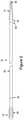
- FIG. 1is an illustration showing one embodiment of a double-ended wire guide.
- FIG. 2is an illustration another embodiment of a double-ended wire guide.
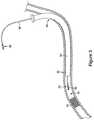
- FIG. 3is an illustration showing a partial cross-sectional view of one stage of a method including the use of one embodiment of a double-ended wire guide.
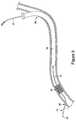
- FIG. 4is an illustration showing a partial cross-sectional view of another stage of a method including the use of one embodiment of a double-ended wire guide.
- FIG. 5is an illustration showing a partial cross-sectional view of yet another stage of a method including the use of one embodiment of a double-ended wire guide.
- One aspect of the present inventionprovides a double-ended wire guide having at least one detachable end.
- a double-ended wire guideallows either end of the wire guide, or both ends sequentially, to be inserted into a body lumen of a human or veterinary patient.
- the body lumenmay, for example, be a passage of the vascular system, the alimentary system, the urogenital system or the biliary system.
- the body lumenis a vessel of the peripheral vascular system.
- the body lumenis an artery of the leg.
- the ends of the wire guidecan have different characteristics.
- the ends of the wire guidemay possess differing stiffness, or may differ in their shape or in their hydrophilic properties.
- Such double-ended wire guidescan allow for the reduction of inventory requirements of wire guides.
- one or both ends of the wire guidedcan include a coiled tip having one or more coils. Differences in the stiffness of such coils can allow for a variation of stiffness of the ends of the wire guide.
- one or both ends of the wire guidemay be tapered or have a reduced thickness compared to the middle portion of the wire guide.
- one or both ends of the wire guideare detachable from the reminder of the wire guide.
- a break-away discontinuityis positioned near at least one end of the wire guide and profies a preferred break point, allowing an end of the wire guide to be separated at a defined position.
- Wire guide 10includes elongated member 20 having a first end region 12 and a second end region 18 .
- first end region 12includes chronic total occlusion (CTO) coiled tip 24 having a designated tip load.
- CTOchronic total occlusion
- coiled tip 24includes a stainless steel and/or a palladium coil.
- FIG. 1also illustrates second end region 18 including tapered end 22 , which, in certain embodiments, is covered by polymer jacket and/or hydrophilic coating 14 .
- tapered end 22is covered by a polymer jacket, a surface of which is covered by a hydrophilic coating.
- the central portion of elongated member 20i.e. the portion between first end region 12 and a second end region 18 , can have a constant stiffness or can vary in stiffness along its length.
- the portion of elongated member 20 between first end region 12 and the center of the wire guidecan have a stiffness that differs from the portion of elongated member 20 between second end region 18 and the center of the wire guide. This can be achieved by, for example, forming these two portions with differing cross sectional dimensions or from different materials.
- the elongated member 20includes a material such as stainless steel, a stainless steel alloy, platinum, palladium, gold, a superelastic nickel-titanium alloy (for example, NITINOL) or combinations thereof.
- a radiopaque materialsuch as platinum or gold, is included as part of the elongated member 20 to allow for better visibility during manipulation of the wire guide within the body of the patient.
- an echogenic materialsuch as tungsten, may be included as part of the elongated member 20 .
- the outside diameter of elongated member 20can be between, for example 0.010 and 0.03 inches, or between 0.015 and 0.025 inches or between 0.025 and 0.020 inches.
- Elongated member 20may have typical wire guide dimensions.
- elongated member 20is between 90 and 400 cm in length.
- elongated member 20is between 280 and 400 cm in length.
- elongated member 20is between 300 and 400 cm in length or is at least 300 cm in length.
- FIG. 1illustrates wire guide 10 including a first break-away discontinuity 16 , which is positioned towards first end region 12 .
- the present embodimentsalso include those in which the first break-away discontinuity is positioned towards second end region 22 .
- First break-away discontinuity 16is typically positioned within 40 cm, or 30 cm, or 20 cm or 10 cm from the end of elongated member 20 .
- First break-away discontinuity 16can be of any construction providing a preferred breaking point in elongated member 20 .
- the break-away discontinuityis a break-away neck, a partial cut, a heat-treated weakened region, a chemically treated weakened region, a hole in the elongated member, a notch in the elongated member, a geometrically induced stress concentration or a localized reduced diameter portion of elongated member 20 .
- FIG. 2illustrates another embodiment of the present invention.
- This embodimentincludes, in addition to first break-away discontinuity 16 , second break-away discontinuity 26 .
- Second break-away discontinuity 26is typically positioned within 40 cm, or 30 cm, or 20 cm or 10 cm from the second end of elongated member 20 .
- the occlusionis a blockage or a partial blockage of the vascular system, the alimentary system, the urogenital system or the biliary system.
- the occlusionis a blockage or a partial blockage of a vessel of the peripheral vascular system, for example, an occlusion of an artery of the leg of a human patient.
- Such an occlusionmay result from peripheral vascular disease, for example atherosclerosis, inflammatory processes leading to stenosis, an embolism, or thrombus formation.
- An occlusion of a vascular vesselmay also reoccur after angioplasty and related procedures performed to aid in alleviating occlusions.
- the cause of these recurring obstructionstermed restenosis, may be due to the body responding to the surgical procedure. Restenosis of the vessel may develop over several months after the procedure, and may require another angioplasty procedure to treat the obstruction.
- Proliferation and migration of smooth muscle cells (SMC) from the media layer of the lumen to the intimal layercause an excessive production of extracellular matrix (ECM), which is believed to be one of the leading contributors to the development of restenosis.
- SMCsmooth muscle cells
- ECMextracellular matrix
- the extensive thickening of tissuesnarrows the lumen of the blood vessel, constricting or blocking the blood flow through the vessel.
- FIGS. 3, 4 and 5illustrate one embodiment of the method of treating such an occlusion.
- the methodincludes introducing the wire guide 40 into the occluded vessel 35 of the patient as a first percutaneous entry point 30 positioned at a first region of the body lumen.
- the wire guide 40is introduced at the first percutaneous entry point 30 through the sheath 55 .
- First end 50 of wire guide 40is then advanced through body lumen 15 of vessel 35 to a first side of an occlusion 45 , through occlusion 45 and is subsequently passed out of body lumen 15 through a second percutaneous entry point 95 .
- first end 50is passed through second percutaneous entry point 95 by pushing the portion of wire guide 40 which remains outside a first percutaneous entry point 30 until first end 50 exits body lumen 15 .
- a wire guide retrieval deviceis passed into body lumen 15 through second percutaneous entry point 95 and used to engage first end 50 of wire guide 40 . The device is then used to pull first end 50 through second percutaneous entry point 95 and out of body lumen 15 .
- FIG. 4illustrates the distal end of a wire guide engagement and withdrawal tool that can be used to pull first end 50 out of body lumen 15 . Further details of the construction of one embodiment of such a tool are disclosed in co-pending patent application Ser. No. 14/369,746, filed Jun. 30, 2014, entitled “Wire Guide Engagement and Withdrawal Tool and Method”, the contents of which are incorporated by reference.
- the distal end of the toolincludes elongated body 90 and gripping portion 80 . In one embodiment, the distal end to the tool is inserted through second percutaneous entry point 95 and gripping portion 80 is engaged to the first end of the wire guide.
- such an engagementmay be achieved by first receiving the first end of the wire guide within a spatial envelope defined by the tool and tightening the tool to engage the wire guide.
- the toolis then withdrawn from the patient lumen through the second percutaneous entry point 95 while engaged with the first end of the wire guide, until the wire guide extends out of the patient at the second percutaneous entry point.
- a portion of the first end of the wire guide extending outside the second percutaneous entry pointcan then be removed to expose a modified terminal end of the wire guide.
- Such a removalcan be achieved by breaking the wire guide at break-away discontinuity 70 .
- the present methodallows for the removal of an end of the wire guide if the end is damaged during, for example, passage through the occlusion, during the snaring process or during the passage out of the lumen. Such damage can make it difficult or impossible for a medical device, such as a stent or balloon to be loaded onto the wire guide. Removal of the damaged end avoids such difficulty and allows the loading of such devices, which may then be then utilized during a subsequent stage of the treatment procedure.
- the present methodcan be used in an angioplasty, stenting and other technique practice for treating an obstructed vessel within the human anatomy.
- the methodcan be used for the treatment of an obstructed artery in the leg.
- a wire guideis first introduced into the artery having the obstruction.
- the wire guideis introduced through a puncture in the groin region of the patient into a region upstream (antegrade) of the obstruction.
- the wire guideis then advanced into the artery and through the obstruction.
- the external anatomy of the patientmay not be conducive to this type of technique.
- force transmission through the wire guide and steeringmay be difficult, especially if the obstruction is far removed from the entry point.
- the antegrade side of the obstructioncan be calcified and especially difficult to puncture from this direction.
- the present methodprovides a technique for crossing such challenging obstructions by accessing the obstructed vessel from a down-stream (retrograde) direction.
- the wire guidemay be introduced through an entry point that is below the knee, for example, in the region of the ankle or foot, and then advanced through the obstruction from a down-stream direction.
- a wire guide introduced in this mannercan be more effective in puncturing the fibrous cap and may be able to be introduced at a point that is closer to the obstruction.
- the wire guidecan then be advanced to a second entry point, usually in the groin region.
- the end of the wire guidecan be either pushed through the second entry point, or snared as disclosed herein, and removed from the artery. If the tip of the wire guide is damaged, the tip can then be removed by breaking the end of the wire guide at break-away discontinuity.
- a stent, balloon or other devicecan then be inserted over the wire guide and advanced to the region of the obstruction to continue treatment of the obstruction. In one embodiment, such a procedure allows for entry of the device through larger diameter vessels of the body, for example of the upper leg.
Landscapes
- Health & Medical Sciences (AREA)
- Life Sciences & Earth Sciences (AREA)
- Heart & Thoracic Surgery (AREA)
- Animal Behavior & Ethology (AREA)
- General Health & Medical Sciences (AREA)
- Public Health (AREA)
- Veterinary Medicine (AREA)
- Surgery (AREA)
- Vascular Medicine (AREA)
- Epidemiology (AREA)
- Engineering & Computer Science (AREA)
- Pulmonology (AREA)
- Biophysics (AREA)
- Anesthesiology (AREA)
- Biomedical Technology (AREA)
- Hematology (AREA)
- Chemical & Material Sciences (AREA)
- Optics & Photonics (AREA)
- Physics & Mathematics (AREA)
- Inorganic Chemistry (AREA)
- Media Introduction/Drainage Providing Device (AREA)
- Chemical Kinetics & Catalysis (AREA)
- Medicinal Chemistry (AREA)
- Polymers & Plastics (AREA)
- Organic Chemistry (AREA)
Abstract
Description
Claims (18)
Priority Applications (2)
| Application Number | Priority Date | Filing Date | Title |
|---|---|---|---|
| US14/823,089US10543344B2 (en) | 2014-08-15 | 2015-08-11 | Double-ended wire guide and method of use thereof |
| US16/752,879US11000677B2 (en) | 2014-08-15 | 2020-01-27 | Double-ended wire guide and method of use thereof |
Applications Claiming Priority (2)
| Application Number | Priority Date | Filing Date | Title |
|---|---|---|---|
| US201462037757P | 2014-08-15 | 2014-08-15 | |
| US14/823,089US10543344B2 (en) | 2014-08-15 | 2015-08-11 | Double-ended wire guide and method of use thereof |
Related Child Applications (1)
| Application Number | Title | Priority Date | Filing Date |
|---|---|---|---|
| US16/752,879ContinuationUS11000677B2 (en) | 2014-08-15 | 2020-01-27 | Double-ended wire guide and method of use thereof |
Publications (2)
| Publication Number | Publication Date |
|---|---|
| US20160045716A1 US20160045716A1 (en) | 2016-02-18 |
| US10543344B2true US10543344B2 (en) | 2020-01-28 |
Family
ID=55301365
Family Applications (2)
| Application Number | Title | Priority Date | Filing Date |
|---|---|---|---|
| US14/823,089Active2036-09-01US10543344B2 (en) | 2014-08-15 | 2015-08-11 | Double-ended wire guide and method of use thereof |
| US16/752,879Active2035-08-15US11000677B2 (en) | 2014-08-15 | 2020-01-27 | Double-ended wire guide and method of use thereof |
Family Applications After (1)
| Application Number | Title | Priority Date | Filing Date |
|---|---|---|---|
| US16/752,879Active2035-08-15US11000677B2 (en) | 2014-08-15 | 2020-01-27 | Double-ended wire guide and method of use thereof |
Country Status (1)
| Country | Link |
|---|---|
| US (2) | US10543344B2 (en) |
Families Citing this family (3)
| Publication number | Priority date | Publication date | Assignee | Title |
|---|---|---|---|---|
| DE102015003026B3 (en)* | 2015-03-06 | 2016-05-19 | Hans Haindl | Security puncture system |
| ES2940133A1 (en) | 2021-10-29 | 2023-05-03 | Quiroga Beltran Inversiones S L | EQUIPMENT AND PROCEDURE FOR COOLING AND SEPARATION OF ALUMINUM SLAG (Machine-translation by Google Translate, not legally binding) |
| US12080851B1 (en) | 2023-03-08 | 2024-09-03 | South 8 Technologies, Inc. | Electrolyte chemical formulations for energy storage devices |
Citations (36)
| Publication number | Priority date | Publication date | Assignee | Title |
|---|---|---|---|---|
| US5122136A (en) | 1990-03-13 | 1992-06-16 | The Regents Of The University Of California | Endovascular electrolytically detachable guidewire tip for the electroformation of thrombus in arteries, veins, aneurysms, vascular malformations and arteriovenous fistulas |
| US5133364A (en) | 1988-06-13 | 1992-07-28 | C. R. Bard, Inc. | Guidewire extension with self-latching detachable connector |
| US5195978A (en) | 1991-12-11 | 1993-03-23 | Baxter International Inc. | Rapid exchange over-the-wire catheter with breakaway feature |
| US5368595A (en) | 1990-09-06 | 1994-11-29 | United States Surgical Corporation | Implant assist apparatus |
| US5423829A (en) | 1993-11-03 | 1995-06-13 | Target Therapeutics, Inc. | Electrolytically severable joint for endovascular embolic devices |
| US5441055A (en) | 1994-06-27 | 1995-08-15 | Cordis Corporation | Guidewire extension wire and connector assembly |
| US5511559A (en) | 1993-05-14 | 1996-04-30 | Schneider (Usa) Inc. | Exchangeable guidewire |
| US5569245A (en) | 1990-03-13 | 1996-10-29 | The Regents Of The University Of California | Detachable endovascular occlusion device activated by alternating electric current |
| US5607406A (en) | 1994-05-17 | 1997-03-04 | Cordis Corporation | Rapid exchange segmented catheter |
| US5776079A (en) | 1996-08-06 | 1998-07-07 | Cook Incorporated | Retrograde-antegrade catheterization guide wire |
| US5813405A (en) | 1990-04-18 | 1998-09-29 | Cordis Corporation | Snap-in connection assembly for extension guidewire system |
| US5890571A (en) | 1995-06-08 | 1999-04-06 | Outrigger, Inc. | Auxiliary luggage holder |
| US5941888A (en) | 1998-02-18 | 1999-08-24 | Target Therapeutics, Inc. | Vaso-occlusive member assembly with multiple detaching points |
| US5964797A (en) | 1996-08-30 | 1999-10-12 | Target Therapeutics, Inc. | Electrolytically deployable braided vaso-occlusion device |
| US6019757A (en) | 1995-07-07 | 2000-02-01 | Target Therapeutics, Inc. | Endoluminal electro-occlusion detection apparatus and method |
| US6022369A (en) | 1998-02-13 | 2000-02-08 | Precision Vascular Systems, Inc. | Wire device with detachable end |
| US6123714A (en) | 1994-12-30 | 2000-09-26 | Target Therapeutics, Inc. | System for detaching an occlusive device within a body using a solderless, electrolytically severable joint |
| US6296622B1 (en) | 1998-12-21 | 2001-10-02 | Micrus Corporation | Endoluminal device delivery system using axially recovering shape memory material |
| US6328702B1 (en) | 1997-10-16 | 2001-12-11 | Scimed Life Systems, Inc. | Guide wire extension system |
| US6346091B1 (en) | 1998-02-13 | 2002-02-12 | Stephen C. Jacobsen | Detachable coil for aneurysm therapy |
| US20020058888A1 (en)* | 1999-12-21 | 2002-05-16 | Biagtan Emmanuel C. | Dock exchange system for composite guidewires |
| US20020133092A1 (en)* | 2001-03-16 | 2002-09-19 | Microvena Corporation | Wire convertible from over-the-wire length to rapid exchange length |
| US6488637B1 (en) | 1996-04-30 | 2002-12-03 | Target Therapeutics, Inc. | Composite endovascular guidewire |
| US6682493B2 (en) | 2001-12-03 | 2004-01-27 | Scimed Life Systems, Inc. | High torque guidewire |
| US20040225233A1 (en) | 2003-05-09 | 2004-11-11 | Frankowski Brian J. | Magnetic guidewires |
| US6911016B2 (en) | 2001-08-06 | 2005-06-28 | Scimed Life Systems, Inc. | Guidewire extension system |
| US20050197597A1 (en) | 2004-03-05 | 2005-09-08 | Medtronic Vascular, Inc. | Guidewire with hollow distal section |
| US7273486B2 (en) | 2003-04-11 | 2007-09-25 | Medtronic Vascular, Inc. | Catheter with a convertible proximal catheter shaft |
| US20080064988A1 (en) | 2006-09-07 | 2008-03-13 | Wilson-Cook Medical Inc. | Loop Tip Wire Guide |
| US7621880B2 (en)* | 2003-09-05 | 2009-11-24 | Vance Products Incorporated | Double ended wire guide |
| US7731669B2 (en) | 2006-05-12 | 2010-06-08 | Concert Medical, Llc | Guidewire formed with composite construction and method for making the same |
| US7758565B2 (en) | 2005-10-18 | 2010-07-20 | Cook Incorporated | Identifiable wire guide |
| US7785274B2 (en) | 2003-12-18 | 2010-08-31 | Terumo Kabushiki Kaisha | Guide wire |
| US20100318001A1 (en) | 2009-06-16 | 2010-12-16 | Asahi Intecc Co., Ltd. | Medical guidewire |
| US20120035707A1 (en)* | 2006-07-31 | 2012-02-09 | Vladimir Mitelberg | Methods of using implantable medical device detachment system |
| US20130204163A1 (en)* | 2012-02-02 | 2013-08-08 | Abbott Cardiovascular Systems, Inc. | Guide wire core wire made from a substantially titanium-free alloy for enhanced guide wire steering response |
- 2015
- 2015-08-11USUS14/823,089patent/US10543344B2/enactiveActive
- 2020
- 2020-01-27USUS16/752,879patent/US11000677B2/enactiveActive
Patent Citations (37)
| Publication number | Priority date | Publication date | Assignee | Title |
|---|---|---|---|---|
| US5133364A (en) | 1988-06-13 | 1992-07-28 | C. R. Bard, Inc. | Guidewire extension with self-latching detachable connector |
| US5122136A (en) | 1990-03-13 | 1992-06-16 | The Regents Of The University Of California | Endovascular electrolytically detachable guidewire tip for the electroformation of thrombus in arteries, veins, aneurysms, vascular malformations and arteriovenous fistulas |
| US5569245A (en) | 1990-03-13 | 1996-10-29 | The Regents Of The University Of California | Detachable endovascular occlusion device activated by alternating electric current |
| US5813405A (en) | 1990-04-18 | 1998-09-29 | Cordis Corporation | Snap-in connection assembly for extension guidewire system |
| US5368595A (en) | 1990-09-06 | 1994-11-29 | United States Surgical Corporation | Implant assist apparatus |
| US5195978A (en) | 1991-12-11 | 1993-03-23 | Baxter International Inc. | Rapid exchange over-the-wire catheter with breakaway feature |
| US5511559A (en) | 1993-05-14 | 1996-04-30 | Schneider (Usa) Inc. | Exchangeable guidewire |
| US5423829A (en) | 1993-11-03 | 1995-06-13 | Target Therapeutics, Inc. | Electrolytically severable joint for endovascular embolic devices |
| US5607406A (en) | 1994-05-17 | 1997-03-04 | Cordis Corporation | Rapid exchange segmented catheter |
| US5441055A (en) | 1994-06-27 | 1995-08-15 | Cordis Corporation | Guidewire extension wire and connector assembly |
| US6123714A (en) | 1994-12-30 | 2000-09-26 | Target Therapeutics, Inc. | System for detaching an occlusive device within a body using a solderless, electrolytically severable joint |
| US5890571A (en) | 1995-06-08 | 1999-04-06 | Outrigger, Inc. | Auxiliary luggage holder |
| US6019757A (en) | 1995-07-07 | 2000-02-01 | Target Therapeutics, Inc. | Endoluminal electro-occlusion detection apparatus and method |
| US6488637B1 (en) | 1996-04-30 | 2002-12-03 | Target Therapeutics, Inc. | Composite endovascular guidewire |
| US5776079A (en) | 1996-08-06 | 1998-07-07 | Cook Incorporated | Retrograde-antegrade catheterization guide wire |
| US5964797A (en) | 1996-08-30 | 1999-10-12 | Target Therapeutics, Inc. | Electrolytically deployable braided vaso-occlusion device |
| US6328702B1 (en) | 1997-10-16 | 2001-12-11 | Scimed Life Systems, Inc. | Guide wire extension system |
| US6022369A (en) | 1998-02-13 | 2000-02-08 | Precision Vascular Systems, Inc. | Wire device with detachable end |
| US6346091B1 (en) | 1998-02-13 | 2002-02-12 | Stephen C. Jacobsen | Detachable coil for aneurysm therapy |
| US5941888A (en) | 1998-02-18 | 1999-08-24 | Target Therapeutics, Inc. | Vaso-occlusive member assembly with multiple detaching points |
| US6296622B1 (en) | 1998-12-21 | 2001-10-02 | Micrus Corporation | Endoluminal device delivery system using axially recovering shape memory material |
| US20020058888A1 (en)* | 1999-12-21 | 2002-05-16 | Biagtan Emmanuel C. | Dock exchange system for composite guidewires |
| US20020133092A1 (en)* | 2001-03-16 | 2002-09-19 | Microvena Corporation | Wire convertible from over-the-wire length to rapid exchange length |
| US8298160B2 (en) | 2001-03-16 | 2012-10-30 | Ev3 Inc. | Wire convertible from over-the-wire length to rapid exchange length |
| US6911016B2 (en) | 2001-08-06 | 2005-06-28 | Scimed Life Systems, Inc. | Guidewire extension system |
| US6682493B2 (en) | 2001-12-03 | 2004-01-27 | Scimed Life Systems, Inc. | High torque guidewire |
| US7273486B2 (en) | 2003-04-11 | 2007-09-25 | Medtronic Vascular, Inc. | Catheter with a convertible proximal catheter shaft |
| US20040225233A1 (en) | 2003-05-09 | 2004-11-11 | Frankowski Brian J. | Magnetic guidewires |
| US7621880B2 (en)* | 2003-09-05 | 2009-11-24 | Vance Products Incorporated | Double ended wire guide |
| US7785274B2 (en) | 2003-12-18 | 2010-08-31 | Terumo Kabushiki Kaisha | Guide wire |
| US20050197597A1 (en) | 2004-03-05 | 2005-09-08 | Medtronic Vascular, Inc. | Guidewire with hollow distal section |
| US7758565B2 (en) | 2005-10-18 | 2010-07-20 | Cook Incorporated | Identifiable wire guide |
| US7731669B2 (en) | 2006-05-12 | 2010-06-08 | Concert Medical, Llc | Guidewire formed with composite construction and method for making the same |
| US20120035707A1 (en)* | 2006-07-31 | 2012-02-09 | Vladimir Mitelberg | Methods of using implantable medical device detachment system |
| US20080064988A1 (en) | 2006-09-07 | 2008-03-13 | Wilson-Cook Medical Inc. | Loop Tip Wire Guide |
| US20100318001A1 (en) | 2009-06-16 | 2010-12-16 | Asahi Intecc Co., Ltd. | Medical guidewire |
| US20130204163A1 (en)* | 2012-02-02 | 2013-08-08 | Abbott Cardiovascular Systems, Inc. | Guide wire core wire made from a substantially titanium-free alloy for enhanced guide wire steering response |
Also Published As
| Publication number | Publication date |
|---|---|
| US20160045716A1 (en) | 2016-02-18 |
| US11000677B2 (en) | 2021-05-11 |
| US20200230370A1 (en) | 2020-07-23 |
Similar Documents
| Publication | Publication Date | Title |
|---|---|---|
| US8961555B2 (en) | Total occlusion guidewire device | |
| CN111629696B (en) | Vascular access devices and methods for lower limb interventions | |
| US4773432A (en) | Bail-out catheter | |
| US8360995B2 (en) | Wire guide | |
| US20170028170A1 (en) | Guide catheter extension device and methods of use for cardiology procedures | |
| US10953197B2 (en) | Guide extension catheter | |
| CN102448534B (en) | Wire support system and wire | |
| US20020133092A1 (en) | Wire convertible from over-the-wire length to rapid exchange length | |
| US20080269675A1 (en) | Interventional medical device system having a slotted section and radiopaque marker and method of making the same | |
| US20110301684A1 (en) | System and method for performing angiography and stenting | |
| US20020055732A1 (en) | Catheter assembly and method for positioning the same at a bifurcated vessel | |
| US11000677B2 (en) | Double-ended wire guide and method of use thereof | |
| US20070293846A1 (en) | Dual Lumen Guidewire Support Catheter | |
| US20100168619A1 (en) | Combination wire guide and method of use thereof | |
| US8167842B2 (en) | Introducer apparatus with cutting edges | |
| US20170143355A1 (en) | Path Creation Through Occlusion | |
| US8777873B2 (en) | Wire guide having a rib for coil attachment | |
| US12053602B2 (en) | Methods and devices for vascular access | |
| US8613713B2 (en) | Wire guide having variable flexibility and method of use thereof | |
| US20110230858A1 (en) | Methods and devices for providing oxygenated blood distal to an obstruction | |
| JPH10165508A (en) | Sunk rescue catheter | |
| WO2010078335A1 (en) | Retrograde wire guide | |
| Okabe et al. | Endovascular Treatment of Subclavian Artery Occlusion by Surgical Exposure of the Proximal Brachial Artery at the Side of an Arteriovenous Fistula | |
| Yoshishige et al. | Perforation of the Brachial Artery During Percutaneous Lower Extremity Angioplasty via the Brachial Artery Approach Resulting in Difficulties in Balloon Catheter Removal: A Case Report | |
| Hadžibegović et al. | Kateter omče za uklanjanje bizarno emboliziranog stenta je prekratak: što ću sada? |
Legal Events
| Date | Code | Title | Description |
|---|---|---|---|
| AS | Assignment | Owner name:GOLZAR, JAAFER, DR., ILLINOIS Free format text:ASSIGNMENT OF ASSIGNORS INTEREST;ASSIGNOR:COOK MEDICAL TECHNOLOGIES LLC;REEL/FRAME:043298/0955 Effective date:20170711 Owner name:COOK INCORPORATED, INDIANA Free format text:ASSIGNMENT OF ASSIGNORS INTEREST;ASSIGNOR:HECHT, NATHAN W.;REEL/FRAME:043298/0673 Effective date:20140819 Owner name:COOK MEDICAL TECHNOLOGIES LLC, INDIANA Free format text:ASSIGNMENT OF ASSIGNORS INTEREST;ASSIGNOR:COOK INCORPORATED;REEL/FRAME:043298/0799 Effective date:20140819 Owner name:COOK MEDICAL TECHNOLOGIES LLC, INDIANA Free format text:ASSIGNMENT OF ASSIGNORS INTEREST;ASSIGNOR:GOLZAR, JAAFER, DR;REEL/FRAME:043298/0879 Effective date:20121022 | |
| STPP | Information on status: patent application and granting procedure in general | Free format text:NON FINAL ACTION MAILED | |
| STPP | Information on status: patent application and granting procedure in general | Free format text:RESPONSE TO NON-FINAL OFFICE ACTION ENTERED AND FORWARDED TO EXAMINER | |
| STPP | Information on status: patent application and granting procedure in general | Free format text:FINAL REJECTION MAILED | |
| STPP | Information on status: patent application and granting procedure in general | Free format text:RESPONSE AFTER FINAL ACTION FORWARDED TO EXAMINER | |
| STPP | Information on status: patent application and granting procedure in general | Free format text:NOTICE OF ALLOWANCE MAILED -- APPLICATION RECEIVED IN OFFICE OF PUBLICATIONS | |
| FEPP | Fee payment procedure | Free format text:ENTITY STATUS SET TO SMALL (ORIGINAL EVENT CODE: SMAL); ENTITY STATUS OF PATENT OWNER: SMALL ENTITY | |
| STPP | Information on status: patent application and granting procedure in general | Free format text:AWAITING TC RESP, ISSUE FEE PAYMENT RECEIVED | |
| STCF | Information on status: patent grant | Free format text:PATENTED CASE | |
| MAFP | Maintenance fee payment | Free format text:PAYMENT OF MAINTENANCE FEE, 4TH YR, SMALL ENTITY (ORIGINAL EVENT CODE: M2551); ENTITY STATUS OF PATENT OWNER: SMALL ENTITY Year of fee payment:4 |