US10543307B2 - Methods and systems for establishing retrograde carotid arterial blood flow - Google Patents
Methods and systems for establishing retrograde carotid arterial blood flowDownload PDFInfo
- Publication number
- US10543307B2 US10543307B2US16/008,703US201816008703AUS10543307B2US 10543307 B2US10543307 B2US 10543307B2US 201816008703 AUS201816008703 AUS 201816008703AUS 10543307 B2US10543307 B2US 10543307B2
- Authority
- US
- United States
- Prior art keywords
- carotid artery
- arterial access
- common carotid
- access sheath
- flow
- Prior art date
- Legal status (The legal status is an assumption and is not a legal conclusion. Google has not performed a legal analysis and makes no representation as to the accuracy of the status listed.)
- Active
Links
Images


Classifications
- G—PHYSICS
- G11—INFORMATION STORAGE
- G11B—INFORMATION STORAGE BASED ON RELATIVE MOVEMENT BETWEEN RECORD CARRIER AND TRANSDUCER
- G11B25/00—Apparatus characterised by the shape of record carrier employed but not specific to the method of recording or reproducing, e.g. dictating apparatus; Combinations of such apparatus
- G11B25/04—Apparatus characterised by the shape of record carrier employed but not specific to the method of recording or reproducing, e.g. dictating apparatus; Combinations of such apparatus using flat record carriers, e.g. disc, card
- G11B25/043—Apparatus characterised by the shape of record carrier employed but not specific to the method of recording or reproducing, e.g. dictating apparatus; Combinations of such apparatus using flat record carriers, e.g. disc, card using rotating discs
- A—HUMAN NECESSITIES
- A61—MEDICAL OR VETERINARY SCIENCE; HYGIENE
- A61M—DEVICES FOR INTRODUCING MEDIA INTO, OR ONTO, THE BODY; DEVICES FOR TRANSDUCING BODY MEDIA OR FOR TAKING MEDIA FROM THE BODY; DEVICES FOR PRODUCING OR ENDING SLEEP OR STUPOR
- A61M1/00—Suction or pumping devices for medical purposes; Devices for carrying-off, for treatment of, or for carrying-over, body-liquids; Drainage systems
- A61M1/36—Other treatment of blood in a by-pass of the natural circulatory system, e.g. temperature adaptation, irradiation ; Extra-corporeal blood circuits
- A61M1/3621—Extra-corporeal blood circuits
- A61M1/3653—Interfaces between patient blood circulation and extra-corporal blood circuit
- A61M1/3655—Arterio-venous shunts or fistulae
- A—HUMAN NECESSITIES
- A61—MEDICAL OR VETERINARY SCIENCE; HYGIENE
- A61B—DIAGNOSIS; SURGERY; IDENTIFICATION
- A61B17/00—Surgical instruments, devices or methods
- A61B17/12—Surgical instruments, devices or methods for ligaturing or otherwise compressing tubular parts of the body, e.g. blood vessels or umbilical cord
- A61B17/12022—Occluding by internal devices, e.g. balloons or releasable wires
- A61B17/12027—Type of occlusion
- A61B17/1204—Type of occlusion temporary occlusion
- A61B17/12045—Type of occlusion temporary occlusion double occlusion, e.g. during anastomosis
- A—HUMAN NECESSITIES
- A61—MEDICAL OR VETERINARY SCIENCE; HYGIENE
- A61B—DIAGNOSIS; SURGERY; IDENTIFICATION
- A61B17/00—Surgical instruments, devices or methods
- A61B17/12—Surgical instruments, devices or methods for ligaturing or otherwise compressing tubular parts of the body, e.g. blood vessels or umbilical cord
- A61B17/12022—Occluding by internal devices, e.g. balloons or releasable wires
- A61B17/12099—Occluding by internal devices, e.g. balloons or releasable wires characterised by the location of the occluder
- A61B17/12109—Occluding by internal devices, e.g. balloons or releasable wires characterised by the location of the occluder in a blood vessel
- A—HUMAN NECESSITIES
- A61—MEDICAL OR VETERINARY SCIENCE; HYGIENE
- A61B—DIAGNOSIS; SURGERY; IDENTIFICATION
- A61B8/00—Diagnosis using ultrasonic, sonic or infrasonic waves
- A61B8/06—Measuring blood flow
- A—HUMAN NECESSITIES
- A61—MEDICAL OR VETERINARY SCIENCE; HYGIENE
- A61B—DIAGNOSIS; SURGERY; IDENTIFICATION
- A61B8/00—Diagnosis using ultrasonic, sonic or infrasonic waves
- A61B8/48—Diagnostic techniques
- A61B8/488—Diagnostic techniques involving Doppler signals
- A—HUMAN NECESSITIES
- A61—MEDICAL OR VETERINARY SCIENCE; HYGIENE
- A61F—FILTERS IMPLANTABLE INTO BLOOD VESSELS; PROSTHESES; DEVICES PROVIDING PATENCY TO, OR PREVENTING COLLAPSING OF, TUBULAR STRUCTURES OF THE BODY, e.g. STENTS; ORTHOPAEDIC, NURSING OR CONTRACEPTIVE DEVICES; FOMENTATION; TREATMENT OR PROTECTION OF EYES OR EARS; BANDAGES, DRESSINGS OR ABSORBENT PADS; FIRST-AID KITS
- A61F2/00—Filters implantable into blood vessels; Prostheses, i.e. artificial substitutes or replacements for parts of the body; Appliances for connecting them with the body; Devices providing patency to, or preventing collapsing of, tubular structures of the body, e.g. stents
- A61F2/82—Devices providing patency to, or preventing collapsing of, tubular structures of the body, e.g. stents
- A—HUMAN NECESSITIES
- A61—MEDICAL OR VETERINARY SCIENCE; HYGIENE
- A61F—FILTERS IMPLANTABLE INTO BLOOD VESSELS; PROSTHESES; DEVICES PROVIDING PATENCY TO, OR PREVENTING COLLAPSING OF, TUBULAR STRUCTURES OF THE BODY, e.g. STENTS; ORTHOPAEDIC, NURSING OR CONTRACEPTIVE DEVICES; FOMENTATION; TREATMENT OR PROTECTION OF EYES OR EARS; BANDAGES, DRESSINGS OR ABSORBENT PADS; FIRST-AID KITS
- A61F2/00—Filters implantable into blood vessels; Prostheses, i.e. artificial substitutes or replacements for parts of the body; Appliances for connecting them with the body; Devices providing patency to, or preventing collapsing of, tubular structures of the body, e.g. stents
- A61F2/95—Instruments specially adapted for placement or removal of stents or stent-grafts
- A—HUMAN NECESSITIES
- A61—MEDICAL OR VETERINARY SCIENCE; HYGIENE
- A61M—DEVICES FOR INTRODUCING MEDIA INTO, OR ONTO, THE BODY; DEVICES FOR TRANSDUCING BODY MEDIA OR FOR TAKING MEDIA FROM THE BODY; DEVICES FOR PRODUCING OR ENDING SLEEP OR STUPOR
- A61M1/00—Suction or pumping devices for medical purposes; Devices for carrying-off, for treatment of, or for carrying-over, body-liquids; Drainage systems
- A61M1/34—Filtering material out of the blood by passing it through a membrane, i.e. hemofiltration or diafiltration
- A—HUMAN NECESSITIES
- A61—MEDICAL OR VETERINARY SCIENCE; HYGIENE
- A61M—DEVICES FOR INTRODUCING MEDIA INTO, OR ONTO, THE BODY; DEVICES FOR TRANSDUCING BODY MEDIA OR FOR TAKING MEDIA FROM THE BODY; DEVICES FOR PRODUCING OR ENDING SLEEP OR STUPOR
- A61M1/00—Suction or pumping devices for medical purposes; Devices for carrying-off, for treatment of, or for carrying-over, body-liquids; Drainage systems
- A61M1/36—Other treatment of blood in a by-pass of the natural circulatory system, e.g. temperature adaptation, irradiation ; Extra-corporeal blood circuits
- A61M1/3613—Reperfusion, e.g. of the coronary vessels, e.g. retroperfusion
- A—HUMAN NECESSITIES
- A61—MEDICAL OR VETERINARY SCIENCE; HYGIENE
- A61M—DEVICES FOR INTRODUCING MEDIA INTO, OR ONTO, THE BODY; DEVICES FOR TRANSDUCING BODY MEDIA OR FOR TAKING MEDIA FROM THE BODY; DEVICES FOR PRODUCING OR ENDING SLEEP OR STUPOR
- A61M1/00—Suction or pumping devices for medical purposes; Devices for carrying-off, for treatment of, or for carrying-over, body-liquids; Drainage systems
- A61M1/36—Other treatment of blood in a by-pass of the natural circulatory system, e.g. temperature adaptation, irradiation ; Extra-corporeal blood circuits
- A61M1/3621—Extra-corporeal blood circuits
- A61M1/3653—Interfaces between patient blood circulation and extra-corporal blood circuit
- A61M1/3659—Cannulae pertaining to extracorporeal circulation
- A—HUMAN NECESSITIES
- A61—MEDICAL OR VETERINARY SCIENCE; HYGIENE
- A61M—DEVICES FOR INTRODUCING MEDIA INTO, OR ONTO, THE BODY; DEVICES FOR TRANSDUCING BODY MEDIA OR FOR TAKING MEDIA FROM THE BODY; DEVICES FOR PRODUCING OR ENDING SLEEP OR STUPOR
- A61M25/00—Catheters; Hollow probes
- A61M25/10—Balloon catheters
- A—HUMAN NECESSITIES
- A61—MEDICAL OR VETERINARY SCIENCE; HYGIENE
- A61M—DEVICES FOR INTRODUCING MEDIA INTO, OR ONTO, THE BODY; DEVICES FOR TRANSDUCING BODY MEDIA OR FOR TAKING MEDIA FROM THE BODY; DEVICES FOR PRODUCING OR ENDING SLEEP OR STUPOR
- A61M29/00—Dilators with or without means for introducing media, e.g. remedies
- A61M29/02—Dilators made of swellable material
- A—HUMAN NECESSITIES
- A61—MEDICAL OR VETERINARY SCIENCE; HYGIENE
- A61M—DEVICES FOR INTRODUCING MEDIA INTO, OR ONTO, THE BODY; DEVICES FOR TRANSDUCING BODY MEDIA OR FOR TAKING MEDIA FROM THE BODY; DEVICES FOR PRODUCING OR ENDING SLEEP OR STUPOR
- A61M39/00—Tubes, tube connectors, tube couplings, valves, access sites or the like, specially adapted for medical use
- A61M39/02—Access sites
- A61M39/06—Haemostasis valves, i.e. gaskets sealing around a needle, catheter or the like, closing on removal thereof
- A—HUMAN NECESSITIES
- A61—MEDICAL OR VETERINARY SCIENCE; HYGIENE
- A61M—DEVICES FOR INTRODUCING MEDIA INTO, OR ONTO, THE BODY; DEVICES FOR TRANSDUCING BODY MEDIA OR FOR TAKING MEDIA FROM THE BODY; DEVICES FOR PRODUCING OR ENDING SLEEP OR STUPOR
- A61M39/00—Tubes, tube connectors, tube couplings, valves, access sites or the like, specially adapted for medical use
- A61M39/22—Valves or arrangement of valves
- A—HUMAN NECESSITIES
- A61—MEDICAL OR VETERINARY SCIENCE; HYGIENE
- A61M—DEVICES FOR INTRODUCING MEDIA INTO, OR ONTO, THE BODY; DEVICES FOR TRANSDUCING BODY MEDIA OR FOR TAKING MEDIA FROM THE BODY; DEVICES FOR PRODUCING OR ENDING SLEEP OR STUPOR
- A61M5/00—Devices for bringing media into the body in a subcutaneous, intra-vascular or intramuscular way; Accessories therefor, e.g. filling or cleaning devices, arm-rests
- A61M5/007—Devices for bringing media into the body in a subcutaneous, intra-vascular or intramuscular way; Accessories therefor, e.g. filling or cleaning devices, arm-rests for contrast media
- G—PHYSICS
- G11—INFORMATION STORAGE
- G11B—INFORMATION STORAGE BASED ON RELATIVE MOVEMENT BETWEEN RECORD CARRIER AND TRANSDUCER
- G11B5/00—Recording by magnetisation or demagnetisation of a record carrier; Reproducing by magnetic means; Record carriers therefor
- G11B5/48—Disposition or mounting of heads or head supports relative to record carriers ; arrangements of heads, e.g. for scanning the record carrier to increase the relative speed
- G11B5/4806—Disposition or mounting of heads or head supports relative to record carriers ; arrangements of heads, e.g. for scanning the record carrier to increase the relative speed specially adapted for disk drive assemblies, e.g. assembly prior to operation, hard or flexible disk drives
- G11B5/4846—Constructional details of the electrical connection between arm and support
- A—HUMAN NECESSITIES
- A61—MEDICAL OR VETERINARY SCIENCE; HYGIENE
- A61B—DIAGNOSIS; SURGERY; IDENTIFICATION
- A61B17/00—Surgical instruments, devices or methods
- A61B2017/00743—Type of operation; Specification of treatment sites
- A61B2017/00778—Operations on blood vessels
- A—HUMAN NECESSITIES
- A61—MEDICAL OR VETERINARY SCIENCE; HYGIENE
- A61B—DIAGNOSIS; SURGERY; IDENTIFICATION
- A61B17/00—Surgical instruments, devices or methods
- A61B17/12—Surgical instruments, devices or methods for ligaturing or otherwise compressing tubular parts of the body, e.g. blood vessels or umbilical cord
- A61B17/12022—Occluding by internal devices, e.g. balloons or releasable wires
- A61B2017/12127—Double occlusion, e.g. for creating blood-free anastomosis site
- A—HUMAN NECESSITIES
- A61—MEDICAL OR VETERINARY SCIENCE; HYGIENE
- A61B—DIAGNOSIS; SURGERY; IDENTIFICATION
- A61B17/00—Surgical instruments, devices or methods
- A61B17/32—Surgical cutting instruments
- A61B17/3205—Excision instruments
- A61B17/3207—Atherectomy devices working by cutting or abrading; Similar devices specially adapted for non-vascular obstructions
- A61B2017/320716—Atherectomy devices working by cutting or abrading; Similar devices specially adapted for non-vascular obstructions comprising means for preventing embolism by dislodged material
- A—HUMAN NECESSITIES
- A61—MEDICAL OR VETERINARY SCIENCE; HYGIENE
- A61F—FILTERS IMPLANTABLE INTO BLOOD VESSELS; PROSTHESES; DEVICES PROVIDING PATENCY TO, OR PREVENTING COLLAPSING OF, TUBULAR STRUCTURES OF THE BODY, e.g. STENTS; ORTHOPAEDIC, NURSING OR CONTRACEPTIVE DEVICES; FOMENTATION; TREATMENT OR PROTECTION OF EYES OR EARS; BANDAGES, DRESSINGS OR ABSORBENT PADS; FIRST-AID KITS
- A61F2/00—Filters implantable into blood vessels; Prostheses, i.e. artificial substitutes or replacements for parts of the body; Appliances for connecting them with the body; Devices providing patency to, or preventing collapsing of, tubular structures of the body, e.g. stents
- A61F2/82—Devices providing patency to, or preventing collapsing of, tubular structures of the body, e.g. stents
- A61F2/86—Stents in a form characterised by the wire-like elements; Stents in the form characterised by a net-like or mesh-like structure
- A61F2/90—Stents in a form characterised by the wire-like elements; Stents in the form characterised by a net-like or mesh-like structure characterised by a net-like or mesh-like structure
- A—HUMAN NECESSITIES
- A61—MEDICAL OR VETERINARY SCIENCE; HYGIENE
- A61F—FILTERS IMPLANTABLE INTO BLOOD VESSELS; PROSTHESES; DEVICES PROVIDING PATENCY TO, OR PREVENTING COLLAPSING OF, TUBULAR STRUCTURES OF THE BODY, e.g. STENTS; ORTHOPAEDIC, NURSING OR CONTRACEPTIVE DEVICES; FOMENTATION; TREATMENT OR PROTECTION OF EYES OR EARS; BANDAGES, DRESSINGS OR ABSORBENT PADS; FIRST-AID KITS
- A61F2/00—Filters implantable into blood vessels; Prostheses, i.e. artificial substitutes or replacements for parts of the body; Appliances for connecting them with the body; Devices providing patency to, or preventing collapsing of, tubular structures of the body, e.g. stents
- A61F2/95—Instruments specially adapted for placement or removal of stents or stent-grafts
- A61F2/954—Instruments specially adapted for placement or removal of stents or stent-grafts for placing stents or stent-grafts in a bifurcation
- A—HUMAN NECESSITIES
- A61—MEDICAL OR VETERINARY SCIENCE; HYGIENE
- A61F—FILTERS IMPLANTABLE INTO BLOOD VESSELS; PROSTHESES; DEVICES PROVIDING PATENCY TO, OR PREVENTING COLLAPSING OF, TUBULAR STRUCTURES OF THE BODY, e.g. STENTS; ORTHOPAEDIC, NURSING OR CONTRACEPTIVE DEVICES; FOMENTATION; TREATMENT OR PROTECTION OF EYES OR EARS; BANDAGES, DRESSINGS OR ABSORBENT PADS; FIRST-AID KITS
- A61F2/00—Filters implantable into blood vessels; Prostheses, i.e. artificial substitutes or replacements for parts of the body; Appliances for connecting them with the body; Devices providing patency to, or preventing collapsing of, tubular structures of the body, e.g. stents
- A61F2/02—Prostheses implantable into the body
- A61F2/04—Hollow or tubular parts of organs, e.g. bladders, tracheae, bronchi or bile ducts
- A61F2/06—Blood vessels
- A61F2002/065—Y-shaped blood vessels
- A—HUMAN NECESSITIES
- A61—MEDICAL OR VETERINARY SCIENCE; HYGIENE
- A61F—FILTERS IMPLANTABLE INTO BLOOD VESSELS; PROSTHESES; DEVICES PROVIDING PATENCY TO, OR PREVENTING COLLAPSING OF, TUBULAR STRUCTURES OF THE BODY, e.g. STENTS; ORTHOPAEDIC, NURSING OR CONTRACEPTIVE DEVICES; FOMENTATION; TREATMENT OR PROTECTION OF EYES OR EARS; BANDAGES, DRESSINGS OR ABSORBENT PADS; FIRST-AID KITS
- A61F2250/00—Special features of prostheses classified in groups A61F2/00 - A61F2/26 or A61F2/82 or A61F9/00 or A61F11/00 or subgroups thereof
- A61F2250/0014—Special features of prostheses classified in groups A61F2/00 - A61F2/26 or A61F2/82 or A61F9/00 or A61F11/00 or subgroups thereof having different values of a given property or geometrical feature, e.g. mechanical property or material property, at different locations within the same prosthesis
- A61F2250/0037—Special features of prostheses classified in groups A61F2/00 - A61F2/26 or A61F2/82 or A61F9/00 or A61F11/00 or subgroups thereof having different values of a given property or geometrical feature, e.g. mechanical property or material property, at different locations within the same prosthesis differing in height or in length
- A—HUMAN NECESSITIES
- A61—MEDICAL OR VETERINARY SCIENCE; HYGIENE
- A61M—DEVICES FOR INTRODUCING MEDIA INTO, OR ONTO, THE BODY; DEVICES FOR TRANSDUCING BODY MEDIA OR FOR TAKING MEDIA FROM THE BODY; DEVICES FOR PRODUCING OR ENDING SLEEP OR STUPOR
- A61M25/00—Catheters; Hollow probes
- A61M25/10—Balloon catheters
- A61M2025/1043—Balloon catheters with special features or adapted for special applications
- A61M2025/1052—Balloon catheters with special features or adapted for special applications for temporarily occluding a vessel for isolating a sector
- A—HUMAN NECESSITIES
- A61—MEDICAL OR VETERINARY SCIENCE; HYGIENE
- A61M—DEVICES FOR INTRODUCING MEDIA INTO, OR ONTO, THE BODY; DEVICES FOR TRANSDUCING BODY MEDIA OR FOR TAKING MEDIA FROM THE BODY; DEVICES FOR PRODUCING OR ENDING SLEEP OR STUPOR
- A61M2205/00—General characteristics of the apparatus
- A61M2205/33—Controlling, regulating or measuring
- A61M2205/3331—Pressure; Flow
- A61M2205/3334—Measuring or controlling the flow rate
Definitions
- Carotid artery diseaseusually consists of deposits of plaque P which narrow the junction between the common carotid artery CCA and the internal carotid artery ICA, an artery which provides blood flow to the brain ( FIG. 5 ). These deposits increase the risk of embolic particles being generated and entering the cerebral vasculature, leading to neurologic consequences such as transient ischemic attacks TIA, ischemic stroke, or death. In addition, should such narrowings become severe, blood flow to the brain is inhibited with serious and sometimes fatal consequences.
- a system with means to occlude the common carotid artery intravascularly, for example with an occlusion element on the arterial access sheath,would allow the entire procedure to be performed using percutaneous techniques.
- a percutaneous approachwould limit the size and associated complications of a surgical incision, as well as enable non-surgical physicians to perform the procedure.
- a method for accessing and treating a carotid arterycomprises forming a penetration in a wall of a common carotid artery; positioning an arterial access sheath through the penetration; blocking blood flow from the common carotid artery past the sheath; allowing retrograde blood flow from the internal carotid artery into the sheath while the common carotid artery remains blocked; and adjusting a rate of retrograde blood flow from the sheath to as high a level as the patient will tolerate, wherein said adjusted rate is a baseline.
- FIGS. 7A and 7Billustrate a tube useful with the sheath of FIG. 6A .
- FIG. 10illustrates an alternative venous return device useful in the methods and systems of the present disclosure.
- the arterial access device 110accesses the common carotid artery via a femoral approach.
- the arterial access device 110approaches the CCA via a percutaneous puncture into the femoral artery FA, such as in the groin, and up the aortic arch AA into the target common carotid artery CCA.
- the venous return device 115can communicate with the jugular vein JV or the femoral vein FV.
- the Circle of Willis CWis the main arterial anastomatic trunk of the brain where all major arteries which supply the brain, namely the two internal carotid arteries (ICAs) and the vertebral basilar system, connect.
- the bloodis carried from the Circle of Willis by the anterior, middle and posterior cerebral arteries to the brain. This communication between arteries makes collateral circulation through the brain possible. Blood flow through alternate routes is made possible thereby providing a safety mechanism in case of blockage to one or more vessels providing blood to the brain.
- the braincan continue receiving adequate blood supply in most instances even when there is a blockage somewhere in the arterial system (e.g., when the ICA is ligated as described herein). Flow through the Circle of Willis ensures adequate cerebral blood flow by numerous pathways that redistribute blood to the deprived side.
- the Circle of Willisis formed by the anterior cerebral arteries ACA and the anterior communicating artery ACoA which connects the two ACAs.
- the two posterior communicating arteries PCoAconnect the Circle of Willis to the two posterior cerebral arteries PCA, which branch from the basilar artery BA and complete the Circle posteriorly.
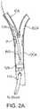
- a tube 705may be provided which is coaxially received over the exterior of the distal sheath 605 , also as seen in FIG. 7A .
- the tube 705has a flared proximal end 710 which engages the adapter 620 and a distal end 715 .
- the distal end 715may be beveled, as shown in FIG. 7B .
- the tube 705may serve at least two purposes. First, the length of the tube 705 limits the introduction of the sheath 605 to the exposed distal portion of the sheath 605 , as seen in FIG. 7A . Second, the tube 705 can engage a pre-deployed puncture closure device disposed in the carotid artery wall, if present, to permit the sheath 605 to be withdrawn without dislodging the closure device.
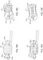
- FIG. 2Bshows an alternative embodiment, wherein the occlusion element 129 can be introduced into the carotid artery on a second sheath 112 separate from the distal sheath 605 of the arterial access device 110 .
- the second or “proximal” sheath 112can be adapted for insertion into the common carotid artery in a proximal or “downward” direction away from the cerebral vasculature.
- the second, proximal sheathcan include an inflatable balloon 129 or other occlusion element, generally as described above.
- the arterial access flow line 615 ( FIG. 6A ) and the venous return flow line 915 , and Y-connectors 620 ( FIG. 6A ) and 1005can each have a relatively large flow lumen inner diameter, typically being in the range from 2.54 mm (0.100 inch) to 5.08 mm (0.200 inch), and a relatively short length, typically being in the range from 10 cm to 20 cm.
- the low system flow resistanceis desirable since it permits the flow to be maximized during portions of a procedure when the risk of emboli is at its greatest.
- the low system flow resistancealso allows the use of a variable flow resistance for controlling flow in the system, as described in more detail below.
- the dimensions of the venous return sheath 910can be generally the same as those described for the arterial access sheath 605 above. In the venous return sheath, an extension for the hemostasis valve 1010 is not required.
- the ability to control the continuous retrograde flow rateallows the physician to adjust the protocol for individual patients and stages of the procedure.
- the retrograde blood flow ratewill typically be controlled over a range from a low rate to a high rate.
- the high ratecan be at least two fold higher than the low rate, typically being at least three fold higher than the low rate, and often being at least five fold higher than the low rate, or even higher.
- the high rateis at least three fold higher than the low rate and in another embodiment the high rate is at least six fold higher than the low rate. While it is generally desirable to have a high retrograde blood flow rate to maximize the extraction of emboli from the carotid arteries, the ability of patients to tolerate retrograde blood flow will vary.
- the retrograde blood flow ratecan be increased above the base line when the stent catheter is being introduced, when the stent is being deployed, pre- and post-dilatation of the stent, removal of the common carotid artery occlusion, and the like.
- variable resistance component 1125 and the pump 1110can be coupled to the shunt 120 to control the retrograde flow rate.
- the variable resistance component 1125controls the flow resistance
- the pump 1110provides for positive displacement of the blood through the shunt 120 .
- the pumpcan be activated to drive the retrograde flow rather than relying on the perfusion stump pressures of the ECA and ICA and the venous back pressure to drive the retrograde flow.
- the pump 1110can be a peristaltic tube pump or any type of pump including a positive displacement pump.
- the pump 1110can be activated and deactivated (either manually or automatically via the controller 1130 ) to selectively achieve blood displacement through the shunt 120 and to control the flow rate through the shunt 120 .
- Displacement of the blood through the shunt 120can also be achieved in other manners including using the aspiration syringe 1120 , or a suction source such as a vacutainer, vaculock syringe, or wall suction may be used.
- the pump 1110can communicate with the controller 1130 .
- the usercan program software in the controller 1130 to enable such automatic control.
- the controller 1130can control actuation of the mechanical portions of the flow control assembly 125 .
- the controller 1130can include circuitry or programming that interprets signals generated by sensors 1135 / 1140 such that the controller 1130 can control actuation of the flow control assembly 125 in response to such signals generated by the sensors.
- the indicatorcan provide a signal indicative of one or more states of the retrograde flow.
- the indicatoridentifies only two discrete states: a state of “high” flow rate and a state of “low” flow rate.
- the indicatoridentifies more than two flow rates, including a “high” flow rate, a “medium” flow rate, and a “low” rate.
- the indicatorcan be configured to identify any quantity of discrete states of the retrograde flow or it can identify a graduated signal that corresponds to the state of the retrograde flow.
- the indicatorcan be a digital or analog meter 1160 that indicates a value of the retrograde flow rate, such as in ml/min or any other units.
- the particular value (such as in ml/min) of either the low flow rate and/or the high flow ratecan be predetermined and/or pre-programmed into the controller such that the user does not actually set or input the value. Rather, the user simply selects “high flow” and/or “low flow” (such as by pressing an actuator such as a button on the controller 1130 ) and the controller 1130 interacts with one or more of the components of the flow control assembly 125 to cause the flow rate to achieve the predetermined high or low flow rate value.
- the usersets or inputs a value for low flow rate and/or high flow rate such as into the controller.
- the low flow rate and/or high flow rateis not actually set. Rather, external data (such as data from the anatomical data sensor 1140 ) is used as the basis for affects the flow rate.
- the flow control actuator 1165can include multiple actuators to switch states from LO-FLOW to HI-FLOW and additional actuators for fine-tuning flow rate within the high flow state and low flow state. Upon switching between LO-FLOW and HI-FLOW, these additional actuators can be used to fine-tune the flow rates within those states.
- LO-FLOWLO-FLOW
- HI-FLOWHI-FLOW
- additional actuatorscan be used to fine-tune the flow rates within those states.
- a wide variety of actuatorscan be used to achieve control over the state of flow.
- the controller 1130 and any of its componentscan interact with other components of the system (such as the pump(s), sensor(s), shunt, etc) in various manners.
- any of a variety of mechanical connectionscan be used to enable communication between the controller 1130 and the system components.
- the controller 1130can communicate electronically or magnetically with the system components.
- Electro-mechanical connectionscan also be used.
- the controller 1130can be equipped with control software that enables the controller to implement control functions with the system components.
- the controlleritself can be a mechanical, electrical or electro-mechanical device.
- the controllercan be mechanically, pneumatically, or hydraulically actuated or electromechanically actuated (for example in the case of solenoid actuation of flow control state).
- the controller 1130can include a computer, computer processor, and memory, as well as data storage capabilities.
- the flow sensor 1135is an ultrasonic or electromagnetic flow meter, which allows for blood flow measurement without contacting the blood through the wall of the shunt 120 .
- An ultrasonic or electromagnetic flow metercan be configured such that it does not have to contact the internal lumen of the shunt 120 .
- the flow sensor 1135at least partially includes a Doppler flow meter, such as a Transonic flow meter, that measures fluid flow through the shunt 120 . It should be appreciated that any of a wide variety of sensor types can be used including an ultrasound flow meter and transducer.
- the systemcan include multiple sensors.
- the controller 1130can set the retrograde flow rate at the “maximum” flow rate that is tolerated by the patient, as assessed by perfusion to the brain.
- the controller 1130can thus control the reverse flow rate to optimize the level of protection for the patient without relying on the user to intercede.
- the feedbackis based on a state of the devices in the system 100 or the interventional tools being used. For example, a sensor may notify the controller 1130 when the system 100 is in a high risk state, such as when an interventional catheter is positioned in the sheath 605 . The controller 1130 then adjusts the flow rate to compensate for such a state.
- FIGS. 21A-21Eflow through the carotid artery bifurcation at different stages of the methods of the present disclosure will be described.
- the distal sheath 605 of the arterial access device 110is introduced into the common carotid artery CCA.
- entry into the common carotid artery CCAcan be via a transcervical or transfemoral approach.
- the blood flowwill continue in antegrade direction AG with flow from the common carotid artery entering both the internal carotid artery ICA and the external carotid artery ECA, as shown in FIG. 21A .
- the venous return device 115is then inserted into a venous return site, such as the internal jugular vein IJV (not shown in FIGS. 21A-21E ).
- the shunt 120is used to connect the flow lines 615 and 915 of the arterial access device 110 and the venous return device 115 , respectively (as shown in FIG. 1A ). In this manner, the shunt 120 provides a passageway for retrograde flow from the atrial access device 110 to the venous return device 115 .
- the shunt 120connects to an external receptacle 130 rather than to the venous return device 115 , as shown in FIG. 1C .
- the occlusion element 129is expanded at a location proximal to the distal opening of the sheath 605 to occlude the CCA.
- the tourniquet 2105FIG. 1A
- the occlusion element 129is introduced on second occlusion device 112 separate from the distal sheath 605 of the arterial access device 110 , as shown in FIG. 2B .
- the ECAmay also be occluded with a separate occlusion element, either on the same device 110 or on a separate occlusion device.
- Flow from the common carotid artery and into the external carotid arterymay then be reestablished by temporarily opening the occluding means present in the artery.
- the resulting flowwill thus be able to flush the common carotid artery which saw slow, turbulent, or stagnant flow during carotid artery occlusion into the external carotid artery.
- the same balloonmay be positioned distally of the stent during reverse flow and forward flow then established by temporarily relieving occlusion of the common carotid artery and flushing.
- the flushing actionoccurs in the stented area to help remove loose or loosely adhering embolic debris in that region.
Landscapes
- Health & Medical Sciences (AREA)
- Heart & Thoracic Surgery (AREA)
- Life Sciences & Earth Sciences (AREA)
- Engineering & Computer Science (AREA)
- Biomedical Technology (AREA)
- Vascular Medicine (AREA)
- Veterinary Medicine (AREA)
- Animal Behavior & Ethology (AREA)
- Public Health (AREA)
- General Health & Medical Sciences (AREA)
- Hematology (AREA)
- Anesthesiology (AREA)
- Cardiology (AREA)
- Surgery (AREA)
- Molecular Biology (AREA)
- Medical Informatics (AREA)
- Nuclear Medicine, Radiotherapy & Molecular Imaging (AREA)
- Biophysics (AREA)
- Pulmonology (AREA)
- Oral & Maxillofacial Surgery (AREA)
- Transplantation (AREA)
- Physics & Mathematics (AREA)
- Reproductive Health (AREA)
- Pathology (AREA)
- Radiology & Medical Imaging (AREA)
- Child & Adolescent Psychology (AREA)
- Surgical Instruments (AREA)
- External Artificial Organs (AREA)
Abstract
Description
Claims (55)
Priority Applications (10)
| Application Number | Priority Date | Filing Date | Title |
|---|---|---|---|
| US16/008,703US10543307B2 (en) | 2007-07-18 | 2018-06-14 | Methods and systems for establishing retrograde carotid arterial blood flow |
| US16/210,533US10286139B2 (en) | 2007-07-18 | 2018-12-05 | Methods and systems for establishing retrograde carotid arterial blood flow |
| US16/377,663US11364332B2 (en) | 2007-07-18 | 2019-04-08 | Methods and systems for establishing retrograde carotid arterial blood flow |
| US16/410,485US10485917B2 (en) | 2007-07-18 | 2019-05-13 | Methods and systems for establishing retrograde carotid arterial blood flow |
| US16/581,061US10709832B2 (en) | 2007-07-18 | 2019-09-24 | Methods and systems for establishing retrograde carotid arterial blood flow |
| US16/894,474US12042593B2 (en) | 2007-07-18 | 2020-06-05 | Methods and systems for establishing retrograde carotid arterial blood flow |
| US17/345,502US12194219B2 (en) | 2007-07-18 | 2021-06-11 | Methods and systems for establishing retrograde carotid arterial blood flow |
| US17/749,454US12296082B2 (en) | 2007-07-18 | 2022-05-20 | Methods and systems for establishing retrograde carotid arterial blood flow |
| US19/016,406US20250144281A1 (en) | 2007-07-18 | 2025-01-10 | Methods and systems for establishing retrograde carotid arterial blood flow |
| US19/205,050US20250269105A1 (en) | 2007-07-18 | 2025-05-12 | Methods and systems for establishing retrograde carotid arterial blood flow |
Applications Claiming Priority (8)
| Application Number | Priority Date | Filing Date | Title |
|---|---|---|---|
| US95038407P | 2007-07-18 | 2007-07-18 | |
| US2630808P | 2008-02-05 | 2008-02-05 | |
| US12/176,250US8157760B2 (en) | 2007-07-18 | 2008-07-18 | Methods and systems for establishing retrograde carotid arterial blood flow |
| US13/050,876US9011364B2 (en) | 2007-07-18 | 2011-03-17 | Methods and systems for establishing retrograde carotid arterial blood flow |
| US14/475,346US9833555B2 (en) | 2007-07-18 | 2014-09-02 | Methods and systems for establishing retrograde carotid arterial blood flow |
| US15/168,809US9789242B2 (en) | 2007-07-18 | 2016-05-31 | Methods and systems for establishing retrograde carotid arterial blood flow |
| US15/728,747US10426885B2 (en) | 2007-07-18 | 2017-10-10 | Methods and systems for establishing retrograde carotid arterial blood flow |
| US16/008,703US10543307B2 (en) | 2007-07-18 | 2018-06-14 | Methods and systems for establishing retrograde carotid arterial blood flow |
Related Parent Applications (1)
| Application Number | Title | Priority Date | Filing Date |
|---|---|---|---|
| US15/728,747ContinuationUS10426885B2 (en) | 2007-07-18 | 2017-10-10 | Methods and systems for establishing retrograde carotid arterial blood flow |
Related Child Applications (1)
| Application Number | Title | Priority Date | Filing Date |
|---|---|---|---|
| US16/210,533ContinuationUS10286139B2 (en) | 2007-07-18 | 2018-12-05 | Methods and systems for establishing retrograde carotid arterial blood flow |
Publications (2)
| Publication Number | Publication Date |
|---|---|
| US20180289884A1 US20180289884A1 (en) | 2018-10-11 |
| US10543307B2true US10543307B2 (en) | 2020-01-28 |
Family
ID=40010940
Family Applications (17)
| Application Number | Title | Priority Date | Filing Date |
|---|---|---|---|
| US12/176,250Active2030-09-03US8157760B2 (en) | 2007-07-18 | 2008-07-18 | Methods and systems for establishing retrograde carotid arterial blood flow |
| US12/835,660Active2029-08-07US8784355B2 (en) | 2007-07-18 | 2010-07-13 | Methods and systems for establishing retrograde carotid arterial blood flow |
| US13/050,855Active2029-03-06US8740834B2 (en) | 2007-07-18 | 2011-03-17 | Methods and systems for establishing retrograde carotid arterial blood flow |
| US13/050,876Active2031-04-10US9011364B2 (en) | 2007-07-18 | 2011-03-17 | Methods and systems for establishing retrograde carotid arterial blood flow |
| US14/475,346Active2029-10-26US9833555B2 (en) | 2007-07-18 | 2014-09-02 | Methods and systems for establishing retrograde carotid arterial blood flow |
| US15/168,809ActiveUS9789242B2 (en) | 2007-07-18 | 2016-05-31 | Methods and systems for establishing retrograde carotid arterial blood flow |
| US15/728,747Active2028-08-18US10426885B2 (en) | 2007-07-18 | 2017-10-10 | Methods and systems for establishing retrograde carotid arterial blood flow |
| US16/008,703ActiveUS10543307B2 (en) | 2007-07-18 | 2018-06-14 | Methods and systems for establishing retrograde carotid arterial blood flow |
| US16/210,533ActiveUS10286139B2 (en) | 2007-07-18 | 2018-12-05 | Methods and systems for establishing retrograde carotid arterial blood flow |
| US16/377,663Active2030-02-18US11364332B2 (en) | 2007-07-18 | 2019-04-08 | Methods and systems for establishing retrograde carotid arterial blood flow |
| US16/410,485ActiveUS10485917B2 (en) | 2007-07-18 | 2019-05-13 | Methods and systems for establishing retrograde carotid arterial blood flow |
| US16/581,061ActiveUS10709832B2 (en) | 2007-07-18 | 2019-09-24 | Methods and systems for establishing retrograde carotid arterial blood flow |
| US16/894,474Active2031-07-05US12042593B2 (en) | 2007-07-18 | 2020-06-05 | Methods and systems for establishing retrograde carotid arterial blood flow |
| US17/345,502Active2030-12-17US12194219B2 (en) | 2007-07-18 | 2021-06-11 | Methods and systems for establishing retrograde carotid arterial blood flow |
| US17/749,454Active2029-06-08US12296082B2 (en) | 2007-07-18 | 2022-05-20 | Methods and systems for establishing retrograde carotid arterial blood flow |
| US19/016,406PendingUS20250144281A1 (en) | 2007-07-18 | 2025-01-10 | Methods and systems for establishing retrograde carotid arterial blood flow |
| US19/205,050PendingUS20250269105A1 (en) | 2007-07-18 | 2025-05-12 | Methods and systems for establishing retrograde carotid arterial blood flow |
Family Applications Before (7)
| Application Number | Title | Priority Date | Filing Date |
|---|---|---|---|
| US12/176,250Active2030-09-03US8157760B2 (en) | 2007-07-18 | 2008-07-18 | Methods and systems for establishing retrograde carotid arterial blood flow |
| US12/835,660Active2029-08-07US8784355B2 (en) | 2007-07-18 | 2010-07-13 | Methods and systems for establishing retrograde carotid arterial blood flow |
| US13/050,855Active2029-03-06US8740834B2 (en) | 2007-07-18 | 2011-03-17 | Methods and systems for establishing retrograde carotid arterial blood flow |
| US13/050,876Active2031-04-10US9011364B2 (en) | 2007-07-18 | 2011-03-17 | Methods and systems for establishing retrograde carotid arterial blood flow |
| US14/475,346Active2029-10-26US9833555B2 (en) | 2007-07-18 | 2014-09-02 | Methods and systems for establishing retrograde carotid arterial blood flow |
| US15/168,809ActiveUS9789242B2 (en) | 2007-07-18 | 2016-05-31 | Methods and systems for establishing retrograde carotid arterial blood flow |
| US15/728,747Active2028-08-18US10426885B2 (en) | 2007-07-18 | 2017-10-10 | Methods and systems for establishing retrograde carotid arterial blood flow |
Family Applications After (9)
| Application Number | Title | Priority Date | Filing Date |
|---|---|---|---|
| US16/210,533ActiveUS10286139B2 (en) | 2007-07-18 | 2018-12-05 | Methods and systems for establishing retrograde carotid arterial blood flow |
| US16/377,663Active2030-02-18US11364332B2 (en) | 2007-07-18 | 2019-04-08 | Methods and systems for establishing retrograde carotid arterial blood flow |
| US16/410,485ActiveUS10485917B2 (en) | 2007-07-18 | 2019-05-13 | Methods and systems for establishing retrograde carotid arterial blood flow |
| US16/581,061ActiveUS10709832B2 (en) | 2007-07-18 | 2019-09-24 | Methods and systems for establishing retrograde carotid arterial blood flow |
| US16/894,474Active2031-07-05US12042593B2 (en) | 2007-07-18 | 2020-06-05 | Methods and systems for establishing retrograde carotid arterial blood flow |
| US17/345,502Active2030-12-17US12194219B2 (en) | 2007-07-18 | 2021-06-11 | Methods and systems for establishing retrograde carotid arterial blood flow |
| US17/749,454Active2029-06-08US12296082B2 (en) | 2007-07-18 | 2022-05-20 | Methods and systems for establishing retrograde carotid arterial blood flow |
| US19/016,406PendingUS20250144281A1 (en) | 2007-07-18 | 2025-01-10 | Methods and systems for establishing retrograde carotid arterial blood flow |
| US19/205,050PendingUS20250269105A1 (en) | 2007-07-18 | 2025-05-12 | Methods and systems for establishing retrograde carotid arterial blood flow |
Country Status (5)
| Country | Link |
|---|---|
| US (17) | US8157760B2 (en) |
| EP (3) | EP2497520B1 (en) |
| JP (2) | JP5290290B2 (en) |
| ES (1) | ES2913223T3 (en) |
| WO (1) | WO2009012473A2 (en) |
Cited By (2)
| Publication number | Priority date | Publication date | Assignee | Title |
|---|---|---|---|---|
| US11844893B2 (en) | 2021-01-17 | 2023-12-19 | Inspire M.D Ltd. | Shunts with blood-flow indicators |
| US12070542B2 (en) | 2021-03-25 | 2024-08-27 | Inspire M.D Ltd. | Device for shunting blood between the arterial and venous systems |
Families Citing this family (181)
| Publication number | Priority date | Publication date | Assignee | Title |
|---|---|---|---|---|
| US8974394B2 (en) | 2001-07-30 | 2015-03-10 | Henry Ford Health System | Device and method for detecting irregular placement of an extracorporeal vascular access needle |
| US7998104B2 (en) | 2003-11-21 | 2011-08-16 | Silk Road Medical, Inc. | Method and apparatus for treating a carotid artery |
| GB0419954D0 (en) | 2004-09-08 | 2004-10-13 | Advotek Medical Devices Ltd | System for directing therapy |
| US20130190676A1 (en) | 2006-04-20 | 2013-07-25 | Limflow Gmbh | Devices and methods for fluid flow through body passages |
| US9511214B2 (en) | 2006-05-02 | 2016-12-06 | Vascular Access Technologies, Inc. | Methods of transvascular retrograde access placement and devices for facilitating therein |
| EP3689274A1 (en) | 2007-02-05 | 2020-08-05 | Boston Scientific Limited | Thrombectomy system |
| US8858490B2 (en) | 2007-07-18 | 2014-10-14 | Silk Road Medical, Inc. | Systems and methods for treating a carotid artery |
| EP2497520B1 (en) | 2007-07-18 | 2022-04-13 | Silk Road Medical, Inc. | Systems for establishing retrograde carotid arterial blood flow |
| US20090198172A1 (en)* | 2008-02-05 | 2009-08-06 | Garrison Michi E | Interventional sheath with retention features |
| JP2011510796A (en) | 2008-02-05 | 2011-04-07 | シルク・ロード・メディカル・インコーポレイテッド | Intervention catheter system and method |
| WO2010019481A1 (en) | 2008-08-11 | 2010-02-18 | Conceptx Medical, Inc. | Systems and methods for treating dyspnea, including via electrical afferent signal blocking |
| EP2323566A2 (en) | 2008-08-13 | 2011-05-25 | Silk Road Medical, Inc. | Suture delivery device |
| US8574245B2 (en) | 2008-08-13 | 2013-11-05 | Silk Road Medical, Inc. | Suture delivery device |
| US9510854B2 (en) | 2008-10-13 | 2016-12-06 | Boston Scientific Scimed, Inc. | Thrombectomy catheter with control box having pressure/vacuum valve for synchronous aspiration and fluid irrigation |
| US9504781B2 (en) | 2008-12-19 | 2016-11-29 | Cvdevices, Llc | Peripheral arterialization devices and methods of using the same |
| US8945039B2 (en)* | 2008-12-19 | 2015-02-03 | Cvdevices, Llc | Devices, systems, and methods for organ retroperfusion |
| US11045300B2 (en) | 2008-12-19 | 2021-06-29 | Cvdevices, Llc | Systems, devices, and methods for organ retroperfusion along with regional mild hypothermia |
| US8888733B2 (en)* | 2008-12-19 | 2014-11-18 | Cvdevices, Llc | Devices, systems, and methods for autoretroperfusion |
| WO2010075445A1 (en)* | 2008-12-23 | 2010-07-01 | Silk Road Medical, Inc. | Methods and systems for treatment of acute ischemic stroke |
| US20100204684A1 (en)* | 2009-01-13 | 2010-08-12 | Garrison Michi E | Methods and systems for performing neurointerventional procedures |
| EP2387427B1 (en) | 2009-01-16 | 2014-08-27 | Claret Medical, Inc. | Intravascular blood filter |
| US9636205B2 (en) | 2009-01-16 | 2017-05-02 | Claret Medical, Inc. | Intravascular blood filters and methods of use |
| US20170202657A1 (en) | 2009-01-16 | 2017-07-20 | Claret Medical, Inc. | Intravascular blood filters and methods of use |
| US9326843B2 (en) | 2009-01-16 | 2016-05-03 | Claret Medical, Inc. | Intravascular blood filters and methods of use |
| WO2010099437A1 (en)* | 2009-02-27 | 2010-09-02 | Silk Road Medical, Inc. | Vessel closure clip device |
| WO2010141752A1 (en)* | 2009-06-03 | 2010-12-09 | Silk Road Medical, Inc. | System and methods for controlling retrograde carotid arterial blood flow |
| US8974489B2 (en) | 2009-07-27 | 2015-03-10 | Claret Medical, Inc. | Dual endovascular filter and methods of use |
| EP2868299B1 (en)* | 2009-08-24 | 2022-08-10 | New Phase Ltd | Phase change and shape change materials |
| WO2011079222A2 (en) | 2009-12-23 | 2011-06-30 | Boston Scientific Scimed, Inc. | Less traumatic method of delivery of mesh-based devices into human body |
| JP5598903B2 (en)* | 2010-01-29 | 2014-10-01 | 富士電機エフテック株式会社 | Electric syringe for chemicals |
| US9555174B2 (en) | 2010-02-17 | 2017-01-31 | Flow Forward Medical, Inc. | Blood pump systems and methods |
| KR101845213B1 (en)* | 2010-02-17 | 2018-05-18 | 플로우 포워드 메디컬, 인크. | System and method to increase the overall diameter of veins |
| US9662431B2 (en) | 2010-02-17 | 2017-05-30 | Flow Forward Medical, Inc. | Blood pump systems and methods |
| US8545552B2 (en) | 2010-02-26 | 2013-10-01 | Silk Road Medical, Inc. | Systems and methods for transcatheter aortic valve treatment |
| CA2793672C (en) | 2010-03-19 | 2020-08-04 | University Of Washington | Drainage systems for excess body fluids |
| US20120302938A1 (en)* | 2010-03-19 | 2012-11-29 | University Of Washington | Drainage systems for excess body fluids and associated methods |
| WO2012021406A2 (en) | 2010-08-12 | 2012-02-16 | Silk Road Medical, Inc. | Systems and methods for treating a carotid artery |
| US20120203265A1 (en)* | 2010-10-14 | 2012-08-09 | Heuser Richard R | Embolism protection device |
| US12150851B2 (en) | 2010-12-30 | 2024-11-26 | Claret Medical, Inc. | Method of isolating the cerebral circulation during a cardiac procedure |
| US9492264B2 (en) | 2010-12-30 | 2016-11-15 | Claret Medical, Inc. | Embolic protection device for protecting the cerebral vasculature |
| US9474451B2 (en)* | 2011-04-01 | 2016-10-25 | Raba Equity Partners Ii, Llc | Systems and methods for varying blood flow to identify autoregulatory ranges in a patient |
| US20130184574A1 (en)* | 2011-07-25 | 2013-07-18 | Richard R. Newhauser, JR. | Devices and methods for transnasal irrigation or suctioning of the sinuses |
| US10779855B2 (en) | 2011-08-05 | 2020-09-22 | Route 92 Medical, Inc. | Methods and systems for treatment of acute ischemic stroke |
| EP4101399B1 (en) | 2011-08-05 | 2025-04-09 | Route 92 Medical, Inc. | System for treatment of acute ischemic stroke |
| US8951222B2 (en)* | 2011-08-10 | 2015-02-10 | Western Vascular Institute | Arterial shunt |
| KR102062132B1 (en) | 2011-08-17 | 2020-01-03 | 플로우 포워드 메디컬, 인크. | Blood pump systems and methods |
| EP2744539B1 (en) | 2011-08-17 | 2022-11-02 | Artio Medical, Inc. | System to increase the overall diameter of a peripheral artery |
| CN103945793B (en)* | 2011-12-06 | 2016-05-04 | 俄奥梯科创新有限公司 | For device and the using method thereof of repairing in aorta lumen |
| US9084857B2 (en)* | 2012-04-16 | 2015-07-21 | W. L. Gore & Associates, Inc. | Single access flow-reversal catheter devices and methods |
| WO2013163322A1 (en) | 2012-04-24 | 2013-10-31 | Cibiem, Inc. | Endovascular catheters and methods for carotid body ablation |
| EP2854681A4 (en) | 2012-06-01 | 2016-02-17 | Cibiem Inc | Percutaneous methods and devices for carotid body ablation |
| WO2013181660A1 (en) | 2012-06-01 | 2013-12-05 | Cibiem, Inc. | Methods and devices for cryogenic carotid body ablation |
| WO2014005155A1 (en) | 2012-06-30 | 2014-01-03 | Cibiem, Inc. | Carotid body ablation via directed energy |
| CN104755010A (en)* | 2012-07-04 | 2015-07-01 | 西比姆公司 | Devices and systems for carotid body ablation |
| US10342699B2 (en) | 2012-08-03 | 2019-07-09 | J.D. Franco & Co., Llc | Systems and methods for treating eye diseases |
| US10159479B2 (en) | 2012-08-09 | 2018-12-25 | Silk Road Medical, Inc. | Suture delivery device |
| US10258730B2 (en) | 2012-08-17 | 2019-04-16 | Flow Forward Medical, Inc. | Blood pump systems and methods |
| US10272269B2 (en) | 2012-11-13 | 2019-04-30 | Silk Road Medical, Inc. | Devices and methods for endoluminal delivery of either fluid or energy for denervation |
| WO2014081970A1 (en)* | 2012-11-21 | 2014-05-30 | Medical Ingenuities, LLC | Radial compression hemostasis band with doppler confirming vascular patency |
| CA2896243A1 (en)* | 2013-01-07 | 2014-07-10 | Henry Ford Health System | Device and method for detecting irregular placement of an extracorporeal vascular access needle |
| US9095344B2 (en) | 2013-02-05 | 2015-08-04 | Artventive Medical Group, Inc. | Methods and apparatuses for blood vessel occlusion |
| US8984733B2 (en) | 2013-02-05 | 2015-03-24 | Artventive Medical Group, Inc. | Bodily lumen occlusion |
| US10835367B2 (en) | 2013-03-08 | 2020-11-17 | Limflow Gmbh | Devices for fluid flow through body passages |
| CA2898879C (en) | 2013-03-08 | 2023-05-02 | Limflow Gmbh | Methods and systems for providing or maintaining fluid flow through body passages |
| WO2014160887A2 (en)* | 2013-03-28 | 2014-10-02 | Silk Road Medical, Inc. | Methods and systems for establishing retrograde carotid arterial blood flow |
| US9693789B2 (en) | 2013-03-29 | 2017-07-04 | Silk Road Medical, Inc. | Systems and methods for aspirating from a body lumen |
| US9636116B2 (en) | 2013-06-14 | 2017-05-02 | Artventive Medical Group, Inc. | Implantable luminal devices |
| US9737308B2 (en)* | 2013-06-14 | 2017-08-22 | Artventive Medical Group, Inc. | Catheter-assisted tumor treatment |
| US9737306B2 (en) | 2013-06-14 | 2017-08-22 | Artventive Medical Group, Inc. | Implantable luminal devices |
| US10149968B2 (en) | 2013-06-14 | 2018-12-11 | Artventive Medical Group, Inc. | Catheter-assisted tumor treatment |
| WO2015017714A2 (en)* | 2013-07-31 | 2015-02-05 | Cvdevices, Llc | Unitary body systems and devices and methods to use the same for retroperfusion |
| EP3047796B1 (en)* | 2013-09-20 | 2020-11-04 | National University Corporation Asahikawa Medical University | Method and system for image processing of intravascular hemodynamics |
| US10549071B2 (en) | 2013-10-15 | 2020-02-04 | Corindus, Inc. | Guide catheter control flexible track |
| US9265512B2 (en) | 2013-12-23 | 2016-02-23 | Silk Road Medical, Inc. | Transcarotid neurovascular catheter |
| AU2015206267B2 (en) | 2014-01-16 | 2018-02-01 | Aqueduct Neurosciences, Inc. | Pressure reference assemblies for body fluid drainage systems and associated methods |
| US8998971B1 (en) | 2014-01-28 | 2015-04-07 | Sanford Health | Pararenal stent graft and methods for use |
| US9980832B2 (en) | 2014-01-28 | 2018-05-29 | Sanford Health | Pararenal and thoracic arch stent graft and methods for use |
| EP3116408B1 (en) | 2014-03-12 | 2018-12-19 | Cibiem, Inc. | Ultrasound ablation catheter |
| US9241699B1 (en) | 2014-09-04 | 2016-01-26 | Silk Road Medical, Inc. | Methods and devices for transcarotid access |
| US9820761B2 (en) | 2014-03-21 | 2017-11-21 | Route 92 Medical, Inc. | Rapid aspiration thrombectomy system and method |
| US9974675B2 (en)* | 2014-04-04 | 2018-05-22 | W. L. Gore & Associates, Inc. | Delivery and deployment systems for bifurcated stent grafts |
| WO2015175537A1 (en) | 2014-05-16 | 2015-11-19 | Silk Road Medical, Inc. | Vessel access and closure assist system and method |
| US9883877B2 (en) | 2014-05-19 | 2018-02-06 | Walk Vascular, Llc | Systems and methods for removal of blood and thrombotic material |
| US9545263B2 (en) | 2014-06-19 | 2017-01-17 | Limflow Gmbh | Devices and methods for treating lower extremity vasculature |
| US11027104B2 (en) | 2014-09-04 | 2021-06-08 | Silk Road Medical, Inc. | Methods and devices for transcarotid access |
| EP3240507A4 (en) | 2014-12-29 | 2018-12-05 | Ocudyne LLC | Apparatus and method for treating eye diseases |
| WO2016115533A1 (en)* | 2015-01-16 | 2016-07-21 | Varjavand Bahram | Flow reversal catheter assembly with emboli detection hub |
| US10426497B2 (en) | 2015-07-24 | 2019-10-01 | Route 92 Medical, Inc. | Anchoring delivery system and methods |
| CN119949953A (en) | 2015-02-04 | 2025-05-09 | 92号医疗公司 | Intravascular access system, dilator and system including dilator |
| US11065019B1 (en) | 2015-02-04 | 2021-07-20 | Route 92 Medical, Inc. | Aspiration catheter systems and methods of use |
| US10405965B2 (en) | 2015-03-25 | 2019-09-10 | Sanford Health | Pararenal and thoracic arch stent graft and methods for use |
| US10238853B2 (en) | 2015-04-10 | 2019-03-26 | Silk Road Medical, Inc. | Methods and systems for establishing retrograde carotid arterial blood flow |
| US9566144B2 (en) | 2015-04-22 | 2017-02-14 | Claret Medical, Inc. | Vascular filters, deflectors, and methods |
| ES2929709T3 (en) | 2015-04-30 | 2022-12-01 | Silk Road Medical Inc | Systems for the treatment of transcatheter aortic valve |
| EP3302304A4 (en) | 2015-06-08 | 2019-02-27 | Richard F. Corrigan Jr. | RADIUS COMPRESSION HEMOSTASE STRIP WITH VASCULAR PERMEABILITY BY CONFIRMATION DOPPLER |
| US11147699B2 (en) | 2015-07-24 | 2021-10-19 | Route 92 Medical, Inc. | Methods of intracerebral implant delivery |
| US10561440B2 (en) | 2015-09-03 | 2020-02-18 | Vesatek, Llc | Systems and methods for manipulating medical devices |
| US10716915B2 (en) | 2015-11-23 | 2020-07-21 | Mivi Neuroscience, Inc. | Catheter systems for applying effective suction in remote vessels and thrombectomy procedures facilitated by catheter systems |
| US10485564B2 (en)* | 2015-12-14 | 2019-11-26 | Mg Stroke Analytics Inc. | Systems and methods to improve perfusion pressure during endovascular intervention |
| ES2991271T3 (en)* | 2016-01-04 | 2024-12-03 | Corflow Therapeutics Ag | System for the treatment of microvascular obstruction |
| WO2017147493A1 (en) | 2016-02-24 | 2017-08-31 | Incept, Llc | Enhanced flexibility neurovascular catheter |
| AU2017229852B2 (en) | 2016-03-09 | 2022-03-03 | J.D. Franco & Co., Llc | Systems and methods for treating eye diseases using retrograde blood flow |
| US10813644B2 (en) | 2016-04-01 | 2020-10-27 | Artventive Medical Group, Inc. | Occlusive implant and delivery system |
| US10492805B2 (en) | 2016-04-06 | 2019-12-03 | Walk Vascular, Llc | Systems and methods for thrombolysis and delivery of an agent |
| EP3445440B1 (en)* | 2016-04-20 | 2023-04-05 | Dignity Health | Systems and methods for a cerebrospinal fluid flow detector |
| AU2017257508B2 (en) | 2016-04-29 | 2021-10-14 | Artio Medical, Inc. | Conduit tips and systems and methods for use |
| US20200009351A1 (en)* | 2016-05-18 | 2020-01-09 | Daniel Ezra Walzman | Carotid Stent Incorporating Arch Fulcrum Catheters and Flow Reversal |
| US11246971B2 (en) | 2016-09-19 | 2022-02-15 | Henry Ford Health System | System and method of monitoring dislodgement of venous needles in dialysis patients |
| US11690985B2 (en) | 2016-09-24 | 2023-07-04 | J.D. Franco & Co., Llc | Systems and methods for single puncture percutaneous reverse blood flow |
| US11045177B2 (en) | 2016-11-02 | 2021-06-29 | Daniel Ezra Walzman | Orientable intracranial occlusion device and method |
| US11638655B2 (en) | 2016-11-02 | 2023-05-02 | Daniel Ezra Walzman | Orientable intracranial occlusion device and method |
| WO2018106858A1 (en) | 2016-12-08 | 2018-06-14 | J.D. Franco & Company | Methods and devices for treating an eye using a filter |
| US10617854B2 (en)* | 2016-12-09 | 2020-04-14 | Vascular Access Technologies, Inc. | Trans-jugular carotid artery access methods |
| US11654224B2 (en) | 2016-12-30 | 2023-05-23 | Vascular Access Technologies, Inc. | Methods and devices for percutaneous implantation of arterio-venous grafts |
| JP7264581B2 (en) | 2017-01-06 | 2023-04-25 | インセプト、リミテッド、ライアビリティ、カンパニー | Antithrombotic coating for aneurysm treatment devices |
| CN110392591B (en) | 2017-01-10 | 2022-06-03 | 92号医疗公司 | Aspiration catheter system and method of use |
| US10864350B2 (en) | 2017-01-20 | 2020-12-15 | Route 92 Medical, Inc. | Single operator intracranial medical device delivery systems and methods of use |
| AU2018213053A1 (en) | 2017-01-25 | 2019-08-29 | J.D. Franco & Co., Llc | Blood vessel access and closure devices and related methods of use |
| US11896245B2 (en)* | 2017-02-09 | 2024-02-13 | Mg Stroke Analytics Inc. | Catheter systems for accessing the brain for treatment of ischemic stroke |
| US10918504B2 (en) | 2017-02-21 | 2021-02-16 | Silk Road Medical, Inc. | Vascular implant |
| US11337790B2 (en) | 2017-02-22 | 2022-05-24 | Boston Scientific Scimed, Inc. | Systems and methods for protecting the cerebral vasculature |
| EP3609415B1 (en) | 2017-04-10 | 2023-08-23 | LimFlow GmbH | Devices for treating lower extremity vasculature |
| US10898212B2 (en) | 2017-05-07 | 2021-01-26 | J.D. Franco & Co., Llc | Devices and methods for treating an artery |
| ES2931538T3 (en) | 2017-07-05 | 2022-12-30 | Silk Road Medical Inc | Methods and devices for transcarotid access |
| US10779929B2 (en) | 2017-10-06 | 2020-09-22 | J.D. Franco & Co., Llc | Treating eye diseases by deploying a stent |
| EP3700464B1 (en) | 2017-10-27 | 2024-02-14 | Boston Scientific Scimed, Inc. | Systems for protecting the cerebral vasculature |
| WO2019089385A1 (en) | 2017-11-02 | 2019-05-09 | Silk Road Medical, Inc. | Fenestrated sheath for embolic protection during transcarotid carotid artery revascularization |
| US10398880B2 (en) | 2017-11-02 | 2019-09-03 | J.D. Franco & Co., Llc | Medical systems, devices, and related methods |
| US10758254B2 (en) | 2017-12-15 | 2020-09-01 | J.D. Franco & Co., Llc | Medical systems, devices, and related methods |
| US11154390B2 (en) | 2017-12-19 | 2021-10-26 | Claret Medical, Inc. | Systems for protection of the cerebral vasculature during a cardiac procedure |
| US11154314B2 (en) | 2018-01-26 | 2021-10-26 | Inari Medical, Inc. | Single insertion delivery system for treating embolism and associated systems and methods |
| US11478249B2 (en) | 2018-02-23 | 2022-10-25 | J.D. Franco & Co., Llc | Ophthalmic artery therapy under reverse flow |
| US11439491B2 (en) | 2018-04-26 | 2022-09-13 | Claret Medical, Inc. | Systems and methods for protecting the cerebral vasculature |
| US11395665B2 (en) | 2018-05-01 | 2022-07-26 | Incept, Llc | Devices and methods for removing obstructive material, from an intravascular site |
| AU2019262972B2 (en) | 2018-05-01 | 2025-02-27 | Incept, Llc | Devices and methods for removing obstructive material from an intravascular site |
| JP7616642B2 (en) | 2018-05-17 | 2025-01-17 | ルート92メディカル・インコーポレイテッド | Suction catheter system and method of use |
| US10716880B2 (en)* | 2018-06-15 | 2020-07-21 | Incuvate, Llc | Systems and methods for aspiration and monitoring |
| US11517335B2 (en) | 2018-07-06 | 2022-12-06 | Incept, Llc | Sealed neurovascular extendable catheter |
| US11471582B2 (en) | 2018-07-06 | 2022-10-18 | Incept, Llc | Vacuum transfer tool for extendable catheter |
| RU2688721C1 (en)* | 2018-07-12 | 2019-05-22 | Евгений Александрович Головин | Method for determining presence of tandem involvement of internal carotid artery in course of its chronic segmental occlusion |
| US11678905B2 (en) | 2018-07-19 | 2023-06-20 | Walk Vascular, Llc | Systems and methods for removal of blood and thrombotic material |
| US10531883B1 (en) | 2018-07-20 | 2020-01-14 | Syntheon 2.0, LLC | Aspiration thrombectomy system and methods for thrombus removal with aspiration catheter |
| JP2021535778A (en) | 2018-08-21 | 2021-12-23 | ボストン サイエンティフィック サイムド, インコーポレイテッドBoston Scientific Scimed, Inc. | A system to protect the cerebrovascular system |
| SG11202102500UA (en) | 2018-10-09 | 2021-04-29 | Limflow Gmbh | Devices and methods for catheter alignment |
| US12285182B2 (en) | 2018-10-10 | 2025-04-29 | Innova Vascular, Inc. | Devices and methods for removing an embolus |
| US11400255B1 (en) | 2018-11-15 | 2022-08-02 | Route 92 Medical, Inc. | Aspiration catheter systems and methods of use |
| US10765843B2 (en) | 2018-12-31 | 2020-09-08 | J.D. Franco & Co., Llc | Intravascular devices, systems, and methods to address eye disorders |
| EP3938024A1 (en) | 2019-03-13 | 2022-01-19 | Abiomed, Inc. | Dual hub introducer sheath |
| US11766539B2 (en) | 2019-03-29 | 2023-09-26 | Incept, Llc | Enhanced flexibility neurovascular catheter |
| US12303413B2 (en) | 2019-06-12 | 2025-05-20 | Daniel Ezra Walzman | Orientable implantable device and method |
| US12364615B2 (en) | 2019-06-12 | 2025-07-22 | Daniel Ezra Walzman | Orientable intracranial occlusion device and method |
| CN110237328A (en)* | 2019-06-24 | 2019-09-17 | 河北医科大学第二医院 | A temporary extracorporeal arteriovenous bypass device |
| WO2021009835A1 (en)* | 2019-07-16 | 2021-01-21 | オリンパス株式会社 | Treatment tool for endoscope |
| US12042152B2 (en)* | 2019-08-21 | 2024-07-23 | Lakshmikumar Pillai | Systems and methods for retrograde perfusion and clearance of emboli |
| US10835258B1 (en) | 2019-08-21 | 2020-11-17 | Lakshmikumar Pillai | Systems and methods for retrograde perfusion and clearance of emboli |
| US12409299B2 (en) | 2019-09-20 | 2025-09-09 | Abiomed, Inc. | Bifurcated hub |
| US11134859B2 (en) | 2019-10-15 | 2021-10-05 | Imperative Care, Inc. | Systems and methods for multivariate stroke detection |
| JP7638273B2 (en) | 2019-10-16 | 2025-03-03 | イナリ メディカル, インコーポレイテッド | Systems, devices and methods for treating vascular obstructions |
| EP4051174A4 (en) | 2019-11-01 | 2023-11-22 | LimFlow GmbH | Devices and methods for increasing blood perfusion to a distal extremity |
| EP4076611A4 (en) | 2019-12-18 | 2023-11-15 | Imperative Care, Inc. | Methods and systems for treating venous thromboembolic disease |
| US11638637B2 (en) | 2019-12-18 | 2023-05-02 | Imperative Care, Inc. | Method of removing embolic material with thrombus engagement tool |
| US20210316127A1 (en) | 2019-12-18 | 2021-10-14 | Imperative Care, Inc. | Hemostasis valve |
| US11406748B2 (en)* | 2020-02-24 | 2022-08-09 | CardiacAssist, Inc | Dual lumen cannula with expandable lumen |
| CN113747934B (en) | 2020-03-10 | 2024-07-09 | 因普瑞缇夫护理公司 | Enhanced flexibility neurovascular catheter |
| US11571555B2 (en)* | 2020-03-16 | 2023-02-07 | Pleural Dynamics, Inc. | Automatic pleural-peritonal pump |
| CN111870798B (en)* | 2020-04-27 | 2023-08-22 | 归创通桥医疗科技股份有限公司 | Novel diversion conduit |
| US11207497B1 (en) | 2020-08-11 | 2021-12-28 | Imperative Care, Inc. | Catheter with enhanced tensile strength |
| WO2022076893A1 (en) | 2020-10-09 | 2022-04-14 | Route 92 Medical, Inc. | Aspiration catheter systems and methods of use |
| US12274458B2 (en) | 2021-02-15 | 2025-04-15 | Walk Vascular, Llc | Systems and methods for removal of blood and thrombotic material |
| JP2024506374A (en) | 2021-02-15 | 2024-02-13 | ウォーク バスキュラー, エルエルシー | System and method for removing blood and thrombotic material |
| US11679195B2 (en) | 2021-04-27 | 2023-06-20 | Contego Medical, Inc. | Thrombus aspiration system and methods for controlling blood loss |
| US20230029243A1 (en)* | 2021-07-26 | 2023-01-26 | Mivi Neuroscience, Inc. | Suction catheter systems with designs allowing improved aspiration and evaluation of aspiration condition |
| US20230052862A1 (en) | 2021-08-12 | 2023-02-16 | Imperative Care, Inc. | Sterile packaging assembly for robotic interventional device |
| US20230067426A1 (en) | 2021-08-31 | 2023-03-02 | Silk Road Medical, Inc. | Detection and pressure relief for percutaneous closure of a vessel |
| USD1077996S1 (en) | 2021-10-18 | 2025-06-03 | Imperative Care, Inc. | Inline fluid filter |
| US11765100B1 (en) | 2022-04-19 | 2023-09-19 | Bank Of America Corporation | System for intelligent capacity planning for resources with high load variance |
| AU2023262477A1 (en) | 2022-04-29 | 2024-12-05 | Relief Cardiovascular, Inc. | Systems, devices, and methods for controllably and selectively occluding, restricting, and diverting flow within a patient's vasculature |
| US11883030B2 (en) | 2022-04-29 | 2024-01-30 | inQB8 Medical Technologies, LLC | Systems, devices, and methods for controllably and selectively occluding, restricting, and diverting flow within a patient's vasculature |
| WO2024215899A1 (en)* | 2023-04-12 | 2024-10-17 | Boston Scientific Medical Device Limited | Sheaths including inbuilt male luer connectors |
| US12280222B2 (en) | 2023-08-28 | 2025-04-22 | Incuvate, Llc | Systems and methods for injection and aspiration |
| US12171917B1 (en) | 2024-01-08 | 2024-12-24 | Imperative Care, Inc. | Devices for blood capture and reintroduction during aspiration procedure |
Citations (402)
| Publication number | Priority date | Publication date | Assignee | Title |
|---|---|---|---|---|
| US3861416A (en) | 1972-02-01 | 1975-01-21 | Ceskoslovenska Akademie Ved | Heart valve |
| US4218313A (en) | 1977-05-23 | 1980-08-19 | Extracorporeal Medical Specialties, Inc. | Dialysis apparatus and technique |
| US4253201A (en) | 1979-05-24 | 1981-03-03 | Ross David A | Prosthesis with self-sealing valve |
| US4301803A (en) | 1978-10-06 | 1981-11-24 | Kuraray Co., Ltd. | Balloon catheter |
| JPS59161808U (en) | 1983-02-10 | 1984-10-30 | 株式会社日本メディカル・サプライ | aortic cannula |
| US4771777A (en) | 1987-01-06 | 1988-09-20 | Advanced Cardiovascular Systems, Inc. | Perfusion type balloon dilatation catheter, apparatus and method |
| US4840690A (en) | 1986-08-25 | 1989-06-20 | Becton, Dickinson And Company | Method of constructing a blood flow conduit |
| US4865581A (en) | 1987-05-29 | 1989-09-12 | Retroperfusion Systems, Inc. | Retroperfusion control apparatus, system and method |
| US4895346A (en) | 1988-05-02 | 1990-01-23 | The Kendall Company | Valve assembly |
| US4921478A (en) | 1988-02-23 | 1990-05-01 | C. R. Bard, Inc. | Cerebral balloon angioplasty system |
| US4921479A (en) | 1987-10-02 | 1990-05-01 | Joseph Grayzel | Catheter sheath with longitudinal seam |
| JPH02237574A (en) | 1988-09-27 | 1990-09-20 | Schneider Europ Ag | Expansion cathetel |
| US5007921A (en) | 1989-10-26 | 1991-04-16 | Brown Alan W | Surgical staple |
| EP0427429A2 (en) | 1989-10-25 | 1991-05-15 | C.R. Bard, Inc. | Occluding catheter for treating cerebral arteries |
| US5026390A (en) | 1989-10-26 | 1991-06-25 | Brown Alan W | Surgical staple |
| US5031636A (en) | 1985-09-18 | 1991-07-16 | C. R. Bard, Inc. | Guide wire extension |
| US5045061A (en) | 1990-02-02 | 1991-09-03 | C. R. Bard, Inc. | Balloon catheter and locking guidewire system |
| US5061275A (en) | 1986-04-21 | 1991-10-29 | Medinvent S.A. | Self-expanding prosthesis |
| US5135484A (en) | 1990-05-09 | 1992-08-04 | Pioneering Technologies, Inc. | Method of removing plaque from vessels |
| US5176652A (en) | 1989-12-22 | 1993-01-05 | Cordis Corporation | Hemostasis valve |
| US5207656A (en) | 1990-04-19 | 1993-05-04 | Cordis Corporation | Medical instrument valve having foam partition member |
| US5250060A (en) | 1992-06-26 | 1993-10-05 | Carbo Paul L | Angioplasty apparatus |
| US5304184A (en) | 1992-10-19 | 1994-04-19 | Indiana University Foundation | Apparatus and method for positive closure of an internal tissue membrane opening |
| US5306250A (en) | 1992-04-02 | 1994-04-26 | Indiana University Foundation | Method and apparatus for intravascular drug delivery |
| US5312356A (en) | 1989-05-22 | 1994-05-17 | Target Therapeutics | Catheter with low-friction distal segment |
| USRE34633E (en) | 1987-11-13 | 1994-06-07 | Cook Incorporated | Balloon guide |
| US5324262A (en) | 1993-02-09 | 1994-06-28 | Cathco, Inc. | Introducer sheath with expandable outer tube and method of use |
| US5328470A (en) | 1989-03-31 | 1994-07-12 | The Regents Of The University Of Michigan | Treatment of diseases by site-specific instillation of cells or site-specific transformation of cells and kits therefor |
| US5328471A (en) | 1990-02-26 | 1994-07-12 | Endoluminal Therapeutics, Inc. | Method and apparatus for treatment of focal disease in hollow tubular organs and other tissue lumens |
| US5380284A (en) | 1993-08-13 | 1995-01-10 | Don Michael; T. Anthony | Obstruction dissolution catheter with variably expanding blocking balloons and method of use |
| US5389090A (en) | 1994-02-07 | 1995-02-14 | Cathco, Inc. | Guiding catheter with straightening dilator |
| WO1995005209A1 (en) | 1993-08-18 | 1995-02-23 | Technology Development Center | Treatment chamber catheter |
| US5403328A (en) | 1992-04-22 | 1995-04-04 | United States Surgical Corporation | Surgical apparatus and method for suturing body tissue |
| US5429609A (en) | 1990-07-26 | 1995-07-04 | Yoon; Inbae | Endoscopic portal for use in endoscopic procedures and methods therefor |
| US5429605A (en) | 1994-01-26 | 1995-07-04 | Target Therapeutics, Inc. | Microballoon catheter |
| US5437632A (en) | 1993-06-02 | 1995-08-01 | Target Therapeutics, Inc. | Variable stiffness balloon catheter |
| US5443454A (en) | 1992-12-09 | 1995-08-22 | Terumo Kabushiki Kaisha | Catheter for embolectomy |
| EP0669103A1 (en) | 1994-02-24 | 1995-08-30 | LaserSurge, Inc. | Surgical crimping device and method of use |
| US5454795A (en) | 1994-06-27 | 1995-10-03 | Target Therapeutics, Inc. | Kink-free spiral-wound catheter |
| JPH07265412A (en) | 1994-03-31 | 1995-10-17 | Terumo Corp | Auxiliary circulating device for blood |
| US5460616A (en) | 1994-04-19 | 1995-10-24 | Cordis Corporation | Catheter introducer with fluid chamber valve |
| US5476450A (en) | 1993-11-04 | 1995-12-19 | Ruggio; Joseph M. | Apparatus and method for aspirating intravascular, pulmonary and cardiac obstructions |
| US5478328A (en) | 1992-05-22 | 1995-12-26 | Silverman; David G. | Methods of minimizing disease transmission by used hypodermic needles, and hypodermic needles adapted for carrying out the method |
| US5484418A (en) | 1991-12-13 | 1996-01-16 | Endovascular Technologies, Inc. | Dual valve reinforced sheath and method |
| US5484412A (en) | 1994-04-19 | 1996-01-16 | Pierpont; Brien E. | Angioplasty method and means for performing angioplasty |
| US5492530A (en) | 1994-02-07 | 1996-02-20 | Cathco, Inc. | Method for accessing the coronary arteries from the radial or brachial artery in the arm |
| US5496294A (en) | 1994-07-08 | 1996-03-05 | Target Therapeutics, Inc. | Catheter with kink-resistant distal tip |
| JPH0871161A (en) | 1994-09-12 | 1996-03-19 | Terumo Corp | Introducer |
| US5520702A (en) | 1994-02-24 | 1996-05-28 | United States Surgical Corporation | Method and apparatus for applying a cinch member to the ends of a suture |
| US5527322A (en) | 1993-11-08 | 1996-06-18 | Perclose, Inc. | Device and method for suturing of internal puncture sites |
| US5542937A (en) | 1994-06-24 | 1996-08-06 | Target Therapeutics, Inc. | Multilumen extruded catheter |
| US5549633A (en) | 1994-08-24 | 1996-08-27 | Kensey Nash Corporation | Apparatus and methods of use for preventing blood seepage at a percutaneous puncture site |
| US5558635A (en) | 1994-12-06 | 1996-09-24 | Medtronic, Inc. | Exchangeable guide system |
| US5573520A (en) | 1991-09-05 | 1996-11-12 | Mayo Foundation For Medical Education And Research | Flexible tubular device for use in medical applications |
| US5584803A (en) | 1991-07-16 | 1996-12-17 | Heartport, Inc. | System for cardiac procedures |
| US5599305A (en) | 1994-10-24 | 1997-02-04 | Cardiovascular Concepts, Inc. | Large-diameter introducer sheath having hemostasis valve and removable steering mechanism |
| US5599326A (en) | 1994-12-20 | 1997-02-04 | Target Therapeutics, Inc. | Catheter with multi-layer section |
| US5613974A (en) | 1992-12-10 | 1997-03-25 | Perclose, Inc. | Apparatus and method for vascular closure |
| US5628754A (en) | 1995-08-01 | 1997-05-13 | Medtronic, Inc. | Stent delivery guide catheter |
| US5643292A (en) | 1995-01-10 | 1997-07-01 | Applied Medical Resources Corporation | Percutaneous suturing device |
| US5649959A (en) | 1995-02-10 | 1997-07-22 | Sherwood Medical Company | Assembly for sealing a puncture in a vessel |
| US5658264A (en) | 1994-11-10 | 1997-08-19 | Target Therapeutics, Inc. | High performance spiral-wound catheter |
| US5667499A (en) | 1994-10-04 | 1997-09-16 | Scimed Life Systems, Inc. | Guide catheter unibody |
| US5669881A (en) | 1995-01-10 | 1997-09-23 | Baxter International Inc. | Vascular introducer system incorporating inflatable occlusion balloon |
| US5674231A (en) | 1995-10-20 | 1997-10-07 | United States Surgical Corporation | Apparatus and method for vascular hole closure |
| US5702373A (en) | 1995-08-31 | 1997-12-30 | Target Therapeutics, Inc. | Composite super-elastic alloy braid reinforced catheter |
| US5707376A (en) | 1992-08-06 | 1998-01-13 | William Cook Europe A/S | Stent introducer and method of use |
| JPH1033666A (en) | 1996-07-19 | 1998-02-10 | Buaayu:Kk | Bypass tube |
| JPH1043192A (en) | 1996-06-11 | 1998-02-17 | Cardiologics Llc | Suture device for blood vessel and the like and method therefor |
| JPH1052490A (en) | 1996-05-02 | 1998-02-24 | Hagiwara Denki Kk | Monitoring device for blood flow status at shunt formation site |
| US5730734A (en) | 1996-11-14 | 1998-03-24 | Scimed Life Systems, Inc. | Catheter systems with interchangeable parts |
| US5749858A (en) | 1993-06-24 | 1998-05-12 | Schneider (Europe) A.G. | Method of using an aspiration catheter |
| US5766183A (en) | 1996-10-21 | 1998-06-16 | Lasersurge, Inc. | Vascular hole closure |
| US5769830A (en) | 1991-06-28 | 1998-06-23 | Cook Incorporated | Soft tip guiding catheter |
| US5769821A (en) | 1992-03-02 | 1998-06-23 | Quinton Instrument Company | Catheter tip retainer |
| US5782800A (en) | 1988-07-22 | 1998-07-21 | Yoon; Inbae | Expandable multifunctional manipulating instruments for various medical procedures and methods therefor |
| US5797929A (en) | 1994-06-01 | 1998-08-25 | Perclose, Inc. | Apparatus and methods for advancing surgical knots |
| WO1998038930A1 (en) | 1997-03-06 | 1998-09-11 | Percusurge, Inc. | Catheter system for containing and removing vascular occlusions |
| US5810869A (en) | 1996-11-18 | 1998-09-22 | Localmed, Inc. | Methods for loading coaxial catheters |
| US5810846A (en) | 1995-08-03 | 1998-09-22 | United States Surgical Corporation | Vascular hole closure |
| US5827229A (en) | 1995-05-24 | 1998-10-27 | Boston Scientific Corporation Northwest Technology Center, Inc. | Percutaneous aspiration thrombectomy catheter system |
| US5833650A (en) | 1995-06-05 | 1998-11-10 | Percusurge, Inc. | Catheter apparatus and method for treating occluded vessels |
| US5836926A (en) | 1996-05-13 | 1998-11-17 | Schneider (Usa) Inc | Intravascular catheter |
| US5846251A (en) | 1996-07-22 | 1998-12-08 | Hart; Charles C. | Access device with expandable containment member |
| US5846253A (en) | 1995-07-14 | 1998-12-08 | C. R. Bard, Inc. | Wound closure apparatus and method |
| US5851210A (en) | 1997-03-21 | 1998-12-22 | Torossian; Richard | Stent delivery system and method |
| US5860990A (en) | 1995-08-24 | 1999-01-19 | Nr Medical, Inc. | Method and apparatus for suturing |
| JPH1142233A (en) | 1996-09-19 | 1999-02-16 | C R Bard Inc | Improved device and method for wound suturing |
| US5876367A (en) | 1996-12-05 | 1999-03-02 | Embol-X, Inc. | Cerebral protection during carotid endarterectomy and downstream vascular protection during other surgeries |
| US5882334A (en) | 1995-12-04 | 1999-03-16 | Target Therapeutics, Inc. | Balloon/delivery catheter assembly with adjustable balloon positioning |
| WO1999015085A1 (en) | 1997-09-25 | 1999-04-01 | Sub-Q, Inc. | Percutaneous hemostatic suturing device and method |
| US5895399A (en) | 1996-07-17 | 1999-04-20 | Embol-X Inc. | Atherectomy device having trapping and excising means for removal of plaque from the aorta and other arteries |
| WO1999025419A1 (en) | 1997-11-14 | 1999-05-27 | Fox Hollow Technologies, Inc. | Recanalization apparatus and devices for use therein and method |
| US5910154A (en) | 1997-05-08 | 1999-06-08 | Embol-X, Inc. | Percutaneous catheter and guidewire having filter and medical device deployment |
| US5913848A (en) | 1996-06-06 | 1999-06-22 | Luther Medical Products, Inc. | Hard tip over-the-needle catheter and method of manufacturing the same |
| US5916193A (en) | 1991-07-16 | 1999-06-29 | Heartport, Inc. | Endovascular cardiac venting catheter and method |
| US5921994A (en) | 1995-06-15 | 1999-07-13 | Perclose, Inc. | Low profile intraluminal suturing device and method |
| US5921952A (en) | 1997-08-14 | 1999-07-13 | Boston Scientific Corporation | Drainage catheter delivery system |
| US5935122A (en) | 1991-12-13 | 1999-08-10 | Endovascular Technologies, Inc. | Dual valve, flexible expandable sheath and method |
| US5938645A (en) | 1995-05-24 | 1999-08-17 | Boston Scientific Corporation Northwest Technology Center Inc. | Percutaneous aspiration catheter system |
| WO1999040945A2 (en) | 1998-02-11 | 1999-08-19 | The Regents Of The University Of California | Combination of a nucleic acid and a vasoactive agent for enhanced gene delivery |
| WO1999045835A2 (en) | 1998-03-13 | 1999-09-16 | Arteria Medical Science, Inc. | Protective device and method against embolization in carotid angioplasty |
| US5976093A (en) | 1990-12-17 | 1999-11-02 | Cardiovascular Imaging Systems, Inc. | Vascular catheter having low-profile distal end |
| US5997508A (en) | 1996-03-28 | 1999-12-07 | Medtronic, Inc. | Expandable percutaneous introducer sheath |
| US6004341A (en) | 1996-12-05 | 1999-12-21 | Loma Linda University Medical Center | Vascular wound closure device |
| US6004310A (en) | 1998-06-17 | 1999-12-21 | Target Therapeutics, Inc. | Multilumen catheter shaft with reinforcement |
| WO1999065420A1 (en) | 1998-06-15 | 1999-12-23 | Gore Enterprise Holdings, Inc. | Remotely removable covering and support |
| WO2000009028A1 (en) | 1998-08-14 | 2000-02-24 | Cardiovention, Inc. | Perfusion catheter system having sutureless arteriotomy seal and methods of use |
| US6030369A (en) | 1997-07-03 | 2000-02-29 | Target Therapeutics Inc. | Micro catheter shaft |
| US6030395A (en) | 1997-05-22 | 2000-02-29 | Kensey Nash Corporation | Anastomosis connection system |
| US6033388A (en) | 1998-04-10 | 2000-03-07 | Medtronic Ave, Inc. | Catheter introducer with thin walled sheath |
| US6042601A (en) | 1998-03-18 | 2000-03-28 | United States Surgical Corporation | Apparatus for vascular hole closure |
| US6053904A (en) | 1996-04-05 | 2000-04-25 | Robert M. Scribner | Thin wall catheter introducer system |
| US6071263A (en) | 1992-03-02 | 2000-06-06 | Kirkman; Thomas R. | Apparatus and method for retaining a catheter in a blood vessel in a fixed position |
| WO2000032266A1 (en) | 1998-12-03 | 2000-06-08 | Benedini, Roberto | Endovascular system for the treatment of stenoses of the carotid and catheter for this system |
| US6074398A (en) | 1998-01-13 | 2000-06-13 | Datascope Investment Corp. | Reduced diameter stent/graft deployment catheter |
| US6090072A (en) | 1992-10-15 | 2000-07-18 | Scimed Life Systems, Inc. | Expandable introducer sheath |
| US6110139A (en) | 1997-10-21 | 2000-08-29 | Loubser; Paul Gerhard | Retrograde perfusion monitoring and control system |
| US6110185A (en) | 1999-01-19 | 2000-08-29 | Medtronic, Inc. | Cannula having integral suture tourniquet |
| US6117144A (en) | 1995-08-24 | 2000-09-12 | Sutura, Inc. | Suturing device and method for sealing an opening in a blood vessel or other biological structure |
| US6117145A (en) | 1994-06-01 | 2000-09-12 | Perclose, Inc. | Method and device for providing hemostasis at vascular penetration sites |
| WO2000056223A1 (en) | 1999-03-19 | 2000-09-28 | By-Pass, Inc. | Vascular closure device |
| US6136010A (en) | 1999-03-04 | 2000-10-24 | Perclose, Inc. | Articulating suturing device and method |
| US6139524A (en) | 1998-10-16 | 2000-10-31 | Scimed Life Systems, Inc. | Stent delivery system with perfusion |
| US6146370A (en) | 1999-04-07 | 2000-11-14 | Coaxia, Inc. | Devices and methods for preventing distal embolization from the internal carotid artery using flow reversal by partial occlusion of the external carotid artery |
| US6146415A (en) | 1999-05-07 | 2000-11-14 | Advanced Cardiovascular Systems, Inc. | Stent delivery system |
| US6146373A (en) | 1997-10-17 | 2000-11-14 | Micro Therapeutics, Inc. | Catheter system and method for injection of a liquid embolic composition and a solidification agent |
| WO2000069350A1 (en) | 1999-05-19 | 2000-11-23 | Innerdyne, Inc. | System and method for establishing vascular access |
| US6152912A (en) | 1997-06-10 | 2000-11-28 | Target Therapeutics, Inc. | Optimized high performance spiral-wound vascular catheter |
| US6159230A (en) | 1997-10-23 | 2000-12-12 | Samuels; Shaun L. W. | Expandable lumen device and method of use |
| US6161547A (en) | 1999-01-15 | 2000-12-19 | Coaxia, Inc. | Medical device for flow augmentation in patients with occlusive cerebrovascular disease and methods of use |
| WO2000076390A2 (en) | 1999-06-14 | 2000-12-21 | Arteria Medical Science, Inc. | Methods and low profile apparatus for reducing embolization during treatment of carotid artery disease |
| US6165199A (en) | 1999-01-12 | 2000-12-26 | Coaxia, Inc. | Medical device for removing thromboembolic material from cerebral arteries and methods of use |
| US6176844B1 (en) | 1997-05-22 | 2001-01-23 | Peter Y. Lee | Catheter system for the isolation of a segment of blood vessel |
| US6190396B1 (en) | 1999-09-14 | 2001-02-20 | Perclose, Inc. | Device and method for deploying and organizing sutures for anastomotic and other attachments |
| US6197042B1 (en) | 2000-01-05 | 2001-03-06 | Medical Technology Group, Inc. | Vascular sheath with puncture site closure apparatus and methods of use |
| US6206868B1 (en) | 1998-03-13 | 2001-03-27 | Arteria Medical Science, Inc. | Protective device and method against embolization during treatment of carotid artery disease |
| US6210370B1 (en) | 1997-01-10 | 2001-04-03 | Applied Medical Resources Corporation | Access device with expandable containment member |
| WO2001034061A1 (en) | 1999-11-11 | 2001-05-17 | Angiomed Gmbh & Co. | Implant delivery device |
| US6258115B1 (en) | 1997-04-23 | 2001-07-10 | Artemis Medical, Inc. | Bifurcated stent and distal protection system |
| US6258080B1 (en) | 1997-07-01 | 2001-07-10 | Target Therapeutics, Inc. | Kink-free spiral-wound catheter |
| WO2001054588A1 (en) | 2000-01-26 | 2001-08-02 | Heartport, Inc. | Vascular incisor and method |
| US6270477B1 (en) | 1996-05-20 | 2001-08-07 | Percusurge, Inc. | Catheter for emboli containment |
| US6287319B1 (en) | 1999-03-30 | 2001-09-11 | Amed Systems, Inc. | Cannula with balloon tip |
| US6295989B1 (en) | 1997-02-06 | 2001-10-02 | Arteria Medical Science, Inc. | ICA angioplasty with cerebral protection |
| US6302898B1 (en) | 1994-06-24 | 2001-10-16 | Advanced Closure Systems, Inc. | Devices for sealing punctures in body vessels |
| US6306163B1 (en) | 1998-08-04 | 2001-10-23 | Advanced Cardiovascular Systems, Inc. | Assembly for collecting emboli and method of use |
| US6306106B1 (en) | 2000-06-19 | 2001-10-23 | Advanced Cardiovascular Systems, Inc. | Diagnostic sheath for reduced embolic risk |
| US20010034509A1 (en) | 1998-05-01 | 2001-10-25 | Cragg Andrew H. | Method of hydrating a sponge material for delivery to a body |
| US20010044634A1 (en) | 2000-03-10 | 2001-11-22 | Don Michael T. Anthony | Vascular embolism prevention device employing filters |
| US20010044638A1 (en) | 1999-07-13 | 2001-11-22 | Scion Cardio-Vascular, Inc. | Suture with toggle and method of manufacture therefor |
| US20010044598A1 (en) | 1998-03-13 | 2001-11-22 | Nicola A. Pisano | Apparatus and methods for reducing embolization during treatment of carotid artery disease |
| US20010044591A1 (en) | 1991-07-16 | 2001-11-22 | Heartport, Inc. | System for cardiac procedures |
| US20010049486A1 (en) | 1999-12-31 | 2001-12-06 | Evans Michael A. | Method and system for re-infusing filtered bodily aspirates |
| US20010049517A1 (en) | 1997-03-06 | 2001-12-06 | Gholam-Reza Zadno-Azizi | Method for containing and removing occlusions in the carotid arteries |
| US6355050B1 (en) | 1992-12-10 | 2002-03-12 | Abbott Laboratories | Device and method for suturing tissue |
| US6358258B1 (en) | 1999-09-14 | 2002-03-19 | Abbott Laboratories | Device and method for performing end-to-side anastomosis |
| US6364900B1 (en) | 1999-07-14 | 2002-04-02 | Richard R. Heuser | Embolism prevention device |
| US6368344B1 (en) | 1999-12-16 | 2002-04-09 | Advanced Cardiovascular Systems, Inc. | Stent deployment system with reinforced inner member |
| US6368316B1 (en) | 1998-06-11 | 2002-04-09 | Target Therapeutics, Inc. | Catheter with composite stiffener |
| WO2002032495A1 (en) | 2000-10-17 | 2002-04-25 | Arteria Medical Science, Inc. | Puncture resistant branch artery occlusion device and methods of use |
| US6379325B1 (en) | 1996-04-24 | 2002-04-30 | The Regents Of The University Of California | Opto-acoustic transducer for medical applications |
| US20020052640A1 (en) | 2000-08-04 | 2002-05-02 | Steve Bigus | Sheath for self-expanding stents |
| US6383172B1 (en) | 1999-04-02 | 2002-05-07 | Coaxia, Inc. | Retrograde venous perfusion with isolation of cerebral circulation |
| US6391048B1 (en) | 2000-01-05 | 2002-05-21 | Integrated Vascular Systems, Inc. | Integrated vascular device with puncture site closure component and sealant and methods of use |
| US20020068899A1 (en) | 2000-12-06 | 2002-06-06 | Rex Medical | Introducer sheath with retainer |
| US20020077600A1 (en) | 2000-12-19 | 2002-06-20 | Laksen Sirimanne | Percutaneous catheter assembly |
| US6413235B1 (en) | 1998-03-13 | 2002-07-02 | Arteria Medical Science, Inc. | Protective device against embolization in carotid angioplasty |
| US6419653B2 (en) | 1992-08-12 | 2002-07-16 | Vidamed, Inc. | Medical probe device and method |
| US6423086B1 (en) | 1995-11-07 | 2002-07-23 | Embol-X, Inc. | Cannula with associated filter and methods of use during cardiac surgery |
| US20020103459A1 (en) | 2000-12-05 | 2002-08-01 | Sparks Kurt D. | Catheter system for vascular re-entry from a sub-intimal space |
| US6428549B1 (en) | 1996-06-11 | 2002-08-06 | X-Site, L.L.C. | Device and method for suturing blood vessels and the like |
| US6435189B1 (en) | 1998-02-03 | 2002-08-20 | Salient Interventional Systems, Inc. | Methods and systems for treating ischemia |
| US20020128679A1 (en) | 2001-03-08 | 2002-09-12 | Embol-X, Inc. | Cerebral protection during carotid endarterectomy and methods of use |
| US6454741B1 (en) | 1997-03-06 | 2002-09-24 | Medtronic Percusurge, Inc. | Aspiration method |
| US6458151B1 (en) | 1999-09-10 | 2002-10-01 | Frank S. Saltiel | Ostial stent positioning device and method |
| US6458103B1 (en) | 1998-10-23 | 2002-10-01 | Scimed Life Systems, Inc. | Axially activated hemostasis valve with lumen size selection |
| US6461364B1 (en) | 2000-01-05 | 2002-10-08 | Integrated Vascular Systems, Inc. | Vascular sheath with bioabsorbable puncture site closure apparatus and methods of use |
| US6464664B1 (en) | 1996-04-26 | 2002-10-15 | Medtronic, Inc. | Method for using intravascular balloon occlusion device |
| US20020151866A1 (en) | 2001-04-11 | 2002-10-17 | Lundkvist Andre-Jean S. | Method and apparatus for intracellular delivery of an agent |
| US6471672B1 (en) | 1999-11-10 | 2002-10-29 | Scimed Life Systems | Selective high pressure dilation balloon |
| US20020165598A1 (en) | 2001-05-01 | 2002-11-07 | Velocimed | Emboli Protection devices and related methods of use |
| US6482172B1 (en) | 2000-02-09 | 2002-11-19 | Jeffrey J. Thramann | Flow-by channel catheter and method of use |
| US20020173815A1 (en) | 1998-05-13 | 2002-11-21 | Michael Hogendijk | Apparatus and methods for reducing embolization during treatment of carotid artery disease |
| US6485500B1 (en) | 2000-03-21 | 2002-11-26 | Advanced Cardiovascular Systems, Inc. | Emboli protection system |
| WO2002096295A1 (en) | 2001-05-30 | 2002-12-05 | Scimed Life Systems, Inc. | Implantable septal defects closure device |
| US20030004543A1 (en) | 1996-10-17 | 2003-01-02 | Malachy Gleeson | Device for closure of puncture wound |
| US6517520B2 (en) | 2000-12-21 | 2003-02-11 | Ethicon Endo Surgery, Inc. | Peripherally inserted catheter with flushable guide-tube |
| US20030032936A1 (en) | 2001-08-10 | 2003-02-13 | Lederman Robert J. | Side-exit catheter and method for its use |
| US20030040762A1 (en) | 2001-08-22 | 2003-02-27 | Gerald Dorros | Apparatus and methods for treating stroke and controlling cerebral flow characteristics |
| US6527746B1 (en)* | 2000-08-03 | 2003-03-04 | Ev3, Inc. | Back-loading catheter |
| US20030050600A1 (en) | 2001-05-01 | 2003-03-13 | Velocimed, L.L.C. | Emboli protection devices and related methods of use |
| US6533800B1 (en) | 2001-07-25 | 2003-03-18 | Coaxia, Inc. | Devices and methods for preventing distal embolization using flow reversal in arteries having collateral blood flow |
| US6540712B1 (en) | 1998-03-13 | 2003-04-01 | Arteria Medical Science, Inc. | Methods and low profile apparatus for reducing embolization during treatment of carotid artery disease |
| US6544276B1 (en) | 1996-05-20 | 2003-04-08 | Medtronic Ave. Inc. | Exchange method for emboli containment |
| US20030069468A1 (en) | 1997-10-09 | 2003-04-10 | Bolling Steven F. | Implantable heart assist system and method of applying same |
| US6555057B1 (en) | 1998-02-25 | 2003-04-29 | Coaxia, Inc. | Intravascular methods and apparatus for isolation and selective cooling of the cerebral vasculature during surgical procedures |
| US6558399B1 (en) | 2000-06-30 | 2003-05-06 | Abbott Laboratories | Devices and method for handling a plurality of suture elements during a suturing procedure |
| US6562049B1 (en) | 2000-03-01 | 2003-05-13 | Cook Vascular Incorporated | Medical introducer apparatus |
| US6562052B2 (en) | 1995-08-24 | 2003-05-13 | Sutura, Inc. | Suturing device and method |
| US6569182B1 (en) | 1998-09-09 | 2003-05-27 | Embol-X, Inc. | Introducer/dilator with balloon protection and methods of use |
| US6582448B1 (en) | 2000-12-21 | 2003-06-24 | Advanced Cardiovascular Systems, Inc. | Vessel occlusion device for embolic protection system |
| US6582396B1 (en) | 1998-05-13 | 2003-06-24 | Arteria Medical Science, Inc. | Puncture resistant balloon for use in carotid artery procedures and methods of use |
| US6582390B1 (en) | 2000-11-08 | 2003-06-24 | Endovascular Technologies, Inc. | Dual lumen peel-away sheath introducer |
| US6589206B1 (en) | 1998-01-23 | 2003-07-08 | Heartport, Inc. | Methods and devices for occluding the ascending aorta and maintaining circulation of oxygenated blood in the patient when the patient's heart is arrested |
| US20030135206A1 (en) | 1998-02-27 | 2003-07-17 | Curon Medical, Inc. | Method for treating a sphincter |
| US6595980B1 (en) | 2001-02-23 | 2003-07-22 | Coaxia, Inc. | Devices and methods for preventing distal embolization using flow reversal by occlusion of the brachiocephalic artery |
| US6596003B1 (en) | 2000-06-28 | 2003-07-22 | Genzyme Corporation | Vascular anastomosis device |
| US20030163086A1 (en) | 2000-05-04 | 2003-08-28 | Stephen Denyer | Fluid delivery device |
| US6612999B2 (en) | 2001-12-06 | 2003-09-02 | Cardiac Pacemakers, Inc. | Balloon actuated guide catheter |
| WO2003071955A2 (en) | 2002-02-21 | 2003-09-04 | Integrated Vascular Systems, Inc. | Closure device and methods for making and using them |
| US6623491B2 (en) | 2001-01-18 | 2003-09-23 | Ev3 Peripheral, Inc. | Stent delivery system with spacer member |
| US6623518B2 (en) | 2001-02-26 | 2003-09-23 | Ev3 Peripheral, Inc. | Implant delivery system with interlock |
| US6626918B1 (en) | 2000-10-06 | 2003-09-30 | Medical Technology Group | Apparatus and methods for positioning a vascular sheath |
| US20030186203A1 (en) | 2002-03-28 | 2003-10-02 | Aboud Emad T. | Method and apparatus for surgical training |
| US6632236B2 (en) | 1999-03-12 | 2003-10-14 | Arteria Medical Science, Inc. | Catheter having radially expandable main body |
| US6635070B2 (en) | 2001-05-21 | 2003-10-21 | Bacchus Vascular, Inc. | Apparatus and methods for capturing particulate material within blood vessels |
| US6638243B2 (en) | 1995-10-06 | 2003-10-28 | Target Therapeutics, Inc. | Balloon catheter with delivery side holes |
| US6638245B2 (en) | 2001-06-26 | 2003-10-28 | Concentric Medical, Inc. | Balloon catheter |
| US6641592B1 (en) | 1999-11-19 | 2003-11-04 | Lsi Solutions, Inc. | System for wound closure |
| JP2003310625A (en) | 2002-04-25 | 2003-11-05 | Terumo Corp | In-vivo tissue suturing device |
| WO2003090831A2 (en) | 2002-04-25 | 2003-11-06 | Arteria Medical Science, Inc. | Infusion catheter having an atraumatic tip |
| WO2003090628A1 (en) | 2002-04-25 | 2003-11-06 | Terumo Kabushiki Kaisha | Organism tissue suturing apparatus |
| US6645160B1 (en) | 2000-03-17 | 2003-11-11 | Christian M. Heesch | Guide support catheter |
| US20030212304A1 (en) | 2002-03-16 | 2003-11-13 | Lattouf Omar M. | Systems and method for practicing counter-cardiac retrograde perfusion |
| US6652480B1 (en) | 1997-03-06 | 2003-11-25 | Medtronic Ave., Inc. | Methods for reducing distal embolization |
| US6656152B2 (en) | 2001-11-16 | 2003-12-02 | Ad-Tech Medical Instrument Corp. | Drug delivery catheter assembly with inflatable balloon |
| US6663652B2 (en) | 1997-03-06 | 2003-12-16 | John M. K. Daniel | Distal protection device and method |
| US20030233065A1 (en) | 2000-10-26 | 2003-12-18 | Jeffrey Steward | Directional needle injection drug delivery device and method of use |
| US6669721B1 (en) | 1998-06-04 | 2003-12-30 | New York University | Endovascular thin film devices and methods for treating and preventing stroke |
| US6673040B1 (en) | 1996-04-16 | 2004-01-06 | Cardeon Corporation | System and methods for catheter procedures with circulatory support in high risk patients |
| WO2004006803A1 (en) | 2002-07-12 | 2004-01-22 | Ev3 Inc. | Device to create proximal stasis |
| US6682505B2 (en) | 1999-03-12 | 2004-01-27 | Arteria Medical Science, Inc. | Catheter for removing emboli from saphenous vein grafts and native coronary arteries |
| US6695867B2 (en) | 2002-02-21 | 2004-02-24 | Integrated Vascular Systems, Inc. | Plunger apparatus and methods for delivering a closure device |
| US6695861B1 (en) | 2002-09-20 | 2004-02-24 | Interrad Medical, Inc. | Sutureless retention device |
| US20040044329A1 (en) | 2002-08-29 | 2004-03-04 | Trudell Leonard A. | Catheter for cardiac injection and method for delivery of therapeutic agents to specified tissues |
| WO2004017865A1 (en) | 2002-08-20 | 2004-03-04 | Devax, Inc. | Endoprosthesis deployment system for treating vascular bifurcations |
| US6702782B2 (en) | 2001-06-26 | 2004-03-09 | Concentric Medical, Inc. | Large lumen balloon catheter |
| US6711436B1 (en) | 1997-08-08 | 2004-03-23 | Duke University | Compositions, apparatus and methods for facilitating surgical procedures |
| WO2004026144A1 (en) | 2002-09-23 | 2004-04-01 | Green David T | Apparatus for suturing a blood vessel |
| US20040064179A1 (en)* | 2001-11-09 | 2004-04-01 | Rubicon Medical, Inc. | Stent delivery device with embolic protection |
| US6719777B2 (en) | 2000-12-07 | 2004-04-13 | Integrated Vascular Systems, Inc. | Closure device and methods for making and using them |
| US6719717B1 (en) | 2000-03-17 | 2004-04-13 | Advanced Research & Technology Institute, Inc. | Thrombectomy treatment system and method |
| US6730102B1 (en) | 2000-11-06 | 2004-05-04 | Abbott Laboratories | Systems, devices and methods for deploying needles |
| US6733517B1 (en) | 2001-06-13 | 2004-05-11 | Alsius Corporation | Angling introducer sheath for catheter having temperature control system |
| US6736790B2 (en) | 1998-02-25 | 2004-05-18 | Denise R. Barbut | Method and system for selective or isolated integrate cerebral perfusion and cooling |
| US6746457B2 (en) | 2001-12-07 | 2004-06-08 | Abbott Laboratories | Snared suture trimmer |
| US6749627B2 (en) | 2001-01-18 | 2004-06-15 | Ev3 Peripheral, Inc. | Grip for stent delivery system |
| US20040116946A1 (en) | 1996-11-07 | 2004-06-17 | St. Jude Medical Atg, Inc. | Medical grafting methods and apparatus |
| US20040122360A1 (en) | 2002-12-23 | 2004-06-24 | Waldhauser Steven L. | Steerable catheter |
| US6755847B2 (en) | 2001-10-05 | 2004-06-29 | Scimed Life Systems, Inc. | Emboli capturing device and method of manufacture therefor |
| US20040127913A1 (en) | 2002-12-31 | 2004-07-01 | Voss Laveille Kao | Systems for anchoring a medical device in a body lumen |
| US6758854B1 (en) | 1997-05-09 | 2004-07-06 | St. Jude Medical | Splittable occlusion balloon sheath and process of use |
| US20040138562A1 (en) | 2002-01-17 | 2004-07-15 | Joshua Makower | Devices, systems and methods for acute or chronic delivery of substances or apparatus to extravascular treatment sites |
| WO2004060169A2 (en) | 2002-12-31 | 2004-07-22 | Integrated Vascular Systems, Inc. | Methods for manufacturing a clip and clip |
| US20040153123A1 (en) | 2003-01-30 | 2004-08-05 | Integrated Vascular Systems, Inc. | Clip applier and methods of use |
| US6783511B2 (en) | 2001-04-12 | 2004-08-31 | Heartport, Inc. | Methods and devices for occluding a patient's ascending aorta and delivering oxygenated blood to the patient |
| US6790197B2 (en) | 2002-09-25 | 2004-09-14 | Becton Dickinson And Company | Single use syringe and plunger rod locking device therefor |
| US20040204675A1 (en) | 2001-09-20 | 2004-10-14 | Seward Kirk Patrick | Microfabricated surgical device for interventional procedures |
| US20040210251A1 (en) | 2003-04-17 | 2004-10-21 | Stavros Kontos | Surgical device |
| US20040215181A1 (en) | 2003-04-25 | 2004-10-28 | Medtronic, Inc. | Delivery of fluid during transurethral prostate treatment |
| US20040215312A1 (en) | 2001-12-03 | 2004-10-28 | Xtent, Inc. | Stent delivery apparatus and method |
| US6827730B1 (en) | 1998-01-13 | 2004-12-07 | Endovascular Technologies, Inc. | Reduced diameter stent/graft deployment catheter |
| US20040249435A1 (en) | 2003-06-09 | 2004-12-09 | Xtent, Inc. | Stent deployment systems and methods |
| US6830579B2 (en) | 2001-05-01 | 2004-12-14 | Coaxia, Inc. | Devices and methods for preventing distal embolization using flow reversal and perfusion augmentation within the cerebral vasculature |
| US20040260333A1 (en) | 1997-11-12 | 2004-12-23 | Dubrul William R. | Medical device and method |
| US20050010238A1 (en) | 2003-07-08 | 2005-01-13 | Potter Daniel J. | Detachable hemostasis valve and splittable sheath assembly |
| US6849068B1 (en) | 1997-03-06 | 2005-02-01 | Medtronic Ave, Inc. | Aspiration catheter |
| US20050049671A1 (en) | 2001-01-04 | 2005-03-03 | Lixiao Wang | Combined shaped balloon and stent protector |
| US6875231B2 (en) | 2002-09-11 | 2005-04-05 | 3F Therapeutics, Inc. | Percutaneously deliverable heart valve |
| US6884235B2 (en) | 2000-12-06 | 2005-04-26 | Rex Medical, L.P. | Introducer sheath with retainer and radiopaque insert |
| US6887227B1 (en) | 2001-02-23 | 2005-05-03 | Coaxia, Inc. | Devices and methods for preventing distal embolization from the vertebrobasilar artery using flow reversal |
| US6902540B2 (en) | 2001-08-22 | 2005-06-07 | Gerald Dorros | Apparatus and methods for treating stroke and controlling cerebral flow characteristics |
| US20050124973A1 (en) | 2001-08-22 | 2005-06-09 | Gerald Dorros | Apparatus and methods for treating stroke and controlling cerebral flow characteristics |
| WO2005051206A1 (en) | 2003-11-21 | 2005-06-09 | Vnus Medical Technologies, Inc. | Method and apparatus for treating a carotid artery |
| US6905505B2 (en) | 1996-07-26 | 2005-06-14 | Kensey Nash Corporation | System and method of use for agent delivery and revascularizing of grafts and vessels |
| US20050131453A1 (en) | 1998-03-13 | 2005-06-16 | Parodi Juan C. | Apparatus and methods for reducing embolization during treatment of carotid artery disease |
| US20050149065A1 (en) | 2003-12-19 | 2005-07-07 | Modesitt D. B. | Device and method for suturing of internal puncture sites |
| US20050154349A1 (en) | 2003-08-08 | 2005-07-14 | Playtex Products, Inc. | Manual breast pump |
| US6929634B2 (en) | 2001-08-22 | 2005-08-16 | Gore Enterprise Holdings, Inc. | Apparatus and methods for treating stroke and controlling cerebral flow characteristics |
| US6932824B1 (en) | 2004-03-02 | 2005-08-23 | St. Jude Medical Puerto Rico B.V. | Three-needle closure device |
| US6936060B2 (en)* | 1998-05-13 | 2005-08-30 | Arteria Medical Sciences, Inc. | Apparatus and methods for removing emboli during a surgical procedure |
| US6942674B2 (en) | 2000-01-05 | 2005-09-13 | Integrated Vascular Systems, Inc. | Apparatus and methods for delivering a closure device |
| US20050228402A1 (en) | 2002-01-24 | 2005-10-13 | Lawrence Hofmann | Methods and devices for percutaneous and surgical interventions |
| US6958059B2 (en) | 1996-05-20 | 2005-10-25 | Medtronic Ave, Inc. | Methods and apparatuses for drug delivery to an intravascular occlusion |
| US20050251162A1 (en) | 2004-05-07 | 2005-11-10 | Usgi Medical Inc. | Apparatus and methods for manipulating and securing tissue |
| US6964668B2 (en) | 1999-03-04 | 2005-11-15 | Abbott Laboratories | Articulating suturing device and method |
| US6972030B2 (en) | 2002-09-17 | 2005-12-06 | Lee Don W | Stent with combined distal protection device |
| US6979346B1 (en) | 2001-08-08 | 2005-12-27 | Advanced Cardiovascular Systems, Inc. | System and method for improved stent retention |
| US20060015171A1 (en) | 2004-07-16 | 2006-01-19 | Armstrong Joseph R | Deployment system for intraluminal devices |
| US20060020270A1 (en) | 2003-01-30 | 2006-01-26 | Ronald Jabba | Clip applier and methods of use |
| US7001400B1 (en) | 1999-03-04 | 2006-02-21 | Abbott Laboratories | Articulating suturing device and method |
| US20060041232A1 (en) | 2004-07-21 | 2006-02-23 | Stearns Ralph A | Introducer assembly with suspended seal |
| US7004931B2 (en) | 2002-03-29 | 2006-02-28 | Gore Enterprise Holdings, Inc. | Proximal catheter assembly having a self-limiting aspiration valve |
| US7004924B1 (en) | 1998-02-11 | 2006-02-28 | Nxstage Medical, Inc. | Methods, systems, and kits for the extracorporeal processing of blood |
| US7022100B1 (en) | 1999-09-03 | 2006-04-04 | A-Med Systems, Inc. | Guidable intravascular blood pump and related methods |
| US7029488B2 (en) | 2001-08-22 | 2006-04-18 | Gore Enterprise Holdings, Inc. | Mechanical thrombectomy device for use in cerebral vessels |
| US7029480B2 (en) | 2001-01-24 | 2006-04-18 | Abott Laboratories | Device and method for suturing of internal puncture sites |
| US7029487B2 (en) | 1998-07-06 | 2006-04-18 | Microvention, Inc. | Vascular embolization with an expansible implant |
| EP1649829A1 (en) | 2004-10-14 | 2006-04-26 | Kieran P. Murphy | Stent delivery system with a balloon for a self-expandable stent |
| US20060106338A1 (en) | 2004-11-18 | 2006-05-18 | Chang David W | Endoluminal delivery of anesthesia |
| US20060111741A1 (en) | 2004-11-23 | 2006-05-25 | Instrasurgical, Llc | Wound closure device |
| US20060129125A1 (en) | 2004-12-09 | 2006-06-15 | Ams Research Corporation | Needleless delivery systems |
| US20060149350A1 (en) | 2003-06-05 | 2006-07-06 | Flowmedica, Inc. | Systems and methods for performing bi-lateral interventions or diagnosis in branched body lumens |
| US20060167437A1 (en) | 2003-06-17 | 2006-07-27 | Flowmedica, Inc. | Method and apparatus for intra aortic substance delivery to a branch vessel |
| US20060167476A1 (en) | 2000-11-06 | 2006-07-27 | Perclose, Inc | Systems, devices and methods for suturing patient tissue |
| US7094246B2 (en) | 2001-12-07 | 2006-08-22 | Abbott Laboratories | Suture trimmer |
| US20060200191A1 (en) | 1996-05-20 | 2006-09-07 | Gholam-Reza Zadno-Azizi | Method and apparatuses for treating an intravascular occlusion |
| US7108677B2 (en) | 2000-05-31 | 2006-09-19 | Kerberos Proximal Solutions, Inc. | Embolization protection system for vascular procedures |
| WO2006128017A2 (en) | 2005-05-25 | 2006-11-30 | The Board Of Trustees Of The Leland Stanford Junior University | Devices and methods for the controlled formation and closure of vascular openings |
| US7144386B2 (en) | 2001-06-29 | 2006-12-05 | Ab Korkor Medical, Inc. | Catheter introducer having an expandable tip |
| US20060282088A1 (en) | 2005-06-08 | 2006-12-14 | Ryan Timothy J | Apparatus and methods for delivering sutures |
| US7150712B2 (en) | 2000-11-07 | 2006-12-19 | Buehlmann Eric L | Target tissue localization assembly and method |
| US20060287673A1 (en) | 2005-04-29 | 2006-12-21 | Zerusa Limited | Interventional medical closure device |
| US7152605B2 (en) | 1998-11-06 | 2006-12-26 | Ev3 Endovascular, Inc. | Adjustable left atrial appendage implant deployment system |
| US20070010787A1 (en) | 2005-07-07 | 2007-01-11 | Hackett Steven S | Embolic protection device and methods of use |
| US7166088B2 (en) | 2003-01-27 | 2007-01-23 | Heuser Richard R | Catheter introducer system |
| US7172621B2 (en) | 2004-09-24 | 2007-02-06 | Laurence Theron | Method of performing protected angioplasty and stenting at a carotid bifurcation |
| US20070078430A1 (en) | 2005-09-15 | 2007-04-05 | Adams Mark L | Method for positioning a catheter guide element in a patient and kit for use in said method |
| US7208008B2 (en) | 2003-10-02 | 2007-04-24 | Medtronic Vascular, Inc. | Balloonless direct stenting device |
| US7223253B2 (en) | 2002-07-29 | 2007-05-29 | Gore Enterprise Holdings, Inc. | Blood aspiration system and methods of use |
| US20070123926A1 (en) | 2005-11-28 | 2007-05-31 | Medtronic Vascular, Inc. | Pre-curved guiding catheter with mechanically actuated occluder for embolic protection |
| US20070123925A1 (en) | 2005-11-28 | 2007-05-31 | Medtronic Vascular, Inc. | Pre-curved guiding catheter with mechanically actuated anchor |
| US7232453B2 (en) | 2001-12-05 | 2007-06-19 | Sagax, Inc. | Endovascular device for entrapment of particulate matter and method for use |
| US7250042B2 (en) | 2003-01-22 | 2007-07-31 | Nipro Corporation | Thrombus suction catheter with improved suction and crossing |
| JP2007244902A (en) | 2007-06-01 | 2007-09-27 | Fujinon Corp | Overtube |
| US20070249997A1 (en) | 2002-09-20 | 2007-10-25 | Flowmedica, Inc. | Method and apparatus for selective material delivery via an intra-renal catheter |
| JP2007301326A (en) | 2006-05-09 | 2007-11-22 | Akio Ichihara | Deep blood vessel puncture appliance |
| US20070270888A1 (en) | 2006-05-16 | 2007-11-22 | Joel Kwan Barrientos | Catheter having end including grooved needle guides |
| WO2007136946A2 (en) | 2001-12-03 | 2007-11-29 | Xtent, Inc. | Delivery catheter having active engagement mechanism for prosthesis |
| US7306585B2 (en) | 2004-09-30 | 2007-12-11 | Engineering Resources Group, Inc. | Guide catheter |
| US7309334B2 (en) | 2002-07-23 | 2007-12-18 | Von Hoffmann Gerard | Intracranial aspiration catheter |
| US20080004636A1 (en) | 2005-07-01 | 2008-01-03 | Abbott Laboratories | Clip applier and methods of use |
| US20080045979A1 (en) | 2006-08-18 | 2008-02-21 | Abbott Laboratories | Articulating suture device and method |
| US7335182B1 (en) | 1998-11-18 | 2008-02-26 | Arthesys | Valved connector with closure operated by axial movement of the valve |
| US20080051676A1 (en) | 2006-08-24 | 2008-02-28 | Melsheimer Jeffry S | Extendable Wire Guide system |
| US20080058839A1 (en) | 2006-02-07 | 2008-03-06 | Nobles Anthony A | Reverse tapered guidewire and method of use |
| US20080086164A1 (en) | 2006-10-04 | 2008-04-10 | Rowe Stanton J | Method and apparatus for reshaping a ventricle |
| US20080097479A1 (en) | 2006-10-20 | 2008-04-24 | Raimar Boehlke | Device and method for vascular closure |
| US7367982B2 (en) | 1996-07-26 | 2008-05-06 | Kensey Nash Corporation | Method for opening a lumen in an occluded blood vessel |
| US7374560B2 (en) | 2001-05-01 | 2008-05-20 | St. Jude Medical, Cardiology Division, Inc. | Emboli protection devices and related methods of use |
| US20080140010A1 (en) | 2006-09-13 | 2008-06-12 | Wilson-Cook Medical Inc. | Medical catheter with stress riser at access port to reduce rupture force |
| US7396359B1 (en) | 1998-05-29 | 2008-07-08 | Bypass, Inc. | Vascular port device |
| US7402151B2 (en) | 2004-12-17 | 2008-07-22 | Biocardia, Inc. | Steerable guide catheters and methods for their use |
| US20080188890A1 (en) | 2006-12-01 | 2008-08-07 | Barry Weitzner | Multi-part instrument systems and methods |
| US20080200946A1 (en) | 2007-02-16 | 2008-08-21 | Reverse Medical Corporation | Occlusion device and method of use |
| US20080208329A1 (en) | 2006-10-20 | 2008-08-28 | Gordon Bishop | Handle mechanism to adjust a medical device |
| US20080221614A1 (en) | 2007-03-09 | 2008-09-11 | Medtronic Vascular, Inc. | Method for Closing an Arteriotomy |
| US20080312666A1 (en) | 2003-01-30 | 2008-12-18 | Abbott Laboratories | Clip applier and methods of use |
| US20090005738A1 (en) | 2007-06-29 | 2009-01-01 | Ethicon Endo-Surgery | Insertion device with floating housing and method of use |
| WO2009012473A2 (en) | 2007-07-18 | 2009-01-22 | Silk Road Medical, Inc. | Methods and systems for establishing retrograde carotid arterial blood flow |
| US20090048654A1 (en) | 2007-08-15 | 2009-02-19 | Wilson-Cook Medical Inc. | Deployment System for Soft Stents |
| US20090076456A1 (en) | 2007-09-14 | 2009-03-19 | Ethicon Endo-Surgery, Inc. | Trocar assembly |
| US7524303B1 (en) | 2004-06-21 | 2009-04-28 | T. Anthony Don Michael | Arterial obstruction treatment kit |
| US7534250B2 (en) | 2002-06-28 | 2009-05-19 | Cook Critical Care | Introducer sheath |
| US20090143789A1 (en) | 2007-12-03 | 2009-06-04 | Houser Russell A | Vascular closure devices, systems, and methods of use |
| US20090157105A1 (en) | 1999-03-04 | 2009-06-18 | Abbott Laboratories | Articulating suturing device and method |
| US20090163864A1 (en) | 2007-12-21 | 2009-06-25 | Breznock Eugene M | Method and apparatus for prevention of catheter air intake |
| US20090198172A1 (en) | 2008-02-05 | 2009-08-06 | Garrison Michi E | Interventional sheath with retention features |
| WO2009100210A1 (en) | 2008-02-05 | 2009-08-13 | Silk Road Medical, Inc. | Interventional catheter system and methods |
| US7578839B2 (en) | 2002-11-27 | 2009-08-25 | Celonova Biosciences, Inc. | Method for treating abdominal aortic aneurysms using a combined laparoscopic/open and endovascular technique |
| US20100042118A1 (en) | 2008-08-13 | 2010-02-18 | Garrison Michi E | Suture delivery device |
| US20100114002A1 (en) | 2004-04-08 | 2010-05-06 | O'mahony John J | Method and apparatus for an extracorporeal control of blood glucose |
| US7731683B2 (en) | 1999-12-22 | 2010-06-08 | Boston Scientific Scimed, Inc. | Endoluminal occlusion-irrigation catheter with aspiration capabilities and methods of use |
| US20100185216A1 (en) | 2008-08-13 | 2010-07-22 | Garrison Michi E | Suture delivery device |
| US7766820B2 (en) | 2002-10-25 | 2010-08-03 | Nmt Medical, Inc. | Expandable sheath tubing |
| US20100204684A1 (en) | 2009-01-13 | 2010-08-12 | Garrison Michi E | Methods and systems for performing neurointerventional procedures |
| US20100217276A1 (en) | 2008-12-23 | 2010-08-26 | Garrison Michi E | Methods and systems for treatment of acute ischemic stroke |
| US20100228269A1 (en) | 2009-02-27 | 2010-09-09 | Garrison Michi E | Vessel closure clip device |
| US7815626B1 (en) | 1998-06-12 | 2010-10-19 | Target Therapeutics, Inc. | Catheter with knit section |
| US20110034986A1 (en) | 2007-07-18 | 2011-02-10 | Chou Tony M | Systems and methods for treating a carotid artery |
| US7905877B1 (en) | 2006-05-12 | 2011-03-15 | Micrus Design Technology, Inc. | Double helix reinforced catheter |
| US7927309B2 (en) | 2007-05-29 | 2011-04-19 | Cordis Corporation | Expandable sheath introducer |
| US20110152625A1 (en) | 2009-12-18 | 2011-06-23 | Tyco Healthcare Group Lp | Surgical portal with rotating seal |
| US7972308B2 (en) | 2003-04-25 | 2011-07-05 | Ad-Tech Medical Instrument Corp. | Intracranial catheter assembly for precise treatment of brain tissue |
| US20110213459A1 (en) | 2010-02-26 | 2011-09-01 | Garrison Michi E | Systems and methods for transcatheter aortic valve treatment |
| US8029533B2 (en) | 2008-04-04 | 2011-10-04 | Accessclosure, Inc. | Apparatus and methods for sealing a vascular puncture |
| US20110270182A1 (en) | 2007-12-21 | 2011-11-03 | Indian Wells Medical, Inc. | Method and Apparatus for Prevention of Catheter Air Intake |
| US8066757B2 (en) | 2007-10-17 | 2011-11-29 | Mindframe, Inc. | Blood flow restoration and thrombus management methods |
| US8083788B2 (en) | 2001-12-03 | 2011-12-27 | Xtent, Inc. | Apparatus and methods for positioning prostheses for deployment from a catheter |
| USRE43300E1 (en) | 1996-12-02 | 2012-04-03 | Abbott Cardiovascular Systems Inc. | Apparatus having stabilization members for percutaneously performing surgery and methods of use |
| US20120083661A1 (en) | 2010-10-01 | 2012-04-05 | Tyco Healthcare Group Lp | Access port |
| US8262622B2 (en) | 2003-10-28 | 2012-09-11 | Applied Medical Resources Corporation | Surgical gel seal |
| US20130035628A1 (en) | 2011-08-05 | 2013-02-07 | Garrison Michi E | Methods and systems for treatment of acute ischemic stroke |
| US20130172661A1 (en) | 2007-10-24 | 2013-07-04 | Circulite, Inc. | Transseptal cannula, tip, delivery system, and method |
| US20130197621A1 (en) | 2010-08-12 | 2013-08-01 | Silk Road Medical, Inc. | Systems and methods for treating a carotid artery |
| US20130281788A1 (en) | 2011-08-05 | 2013-10-24 | Silk Road Medical, Inc. | Methods and systems for treatment of acute ischemic stroke |
| US20130331655A1 (en) | 2012-05-08 | 2013-12-12 | Cook Medical Technologies Llc | Access port |
| US20140031682A1 (en) | 2009-06-03 | 2014-01-30 | Silk Road Medical, Inc. | System and methods for controlling retrograde carotid arterial blood flow |
| US20140046346A1 (en) | 2012-08-09 | 2014-02-13 | Silk Road Medical, Inc. | Suture Delivery Device |
| US20140135661A1 (en) | 2012-11-13 | 2014-05-15 | Silk Road Medical, Inc. | Devices and methods for endoluminal delivery of either fluid or energy for denervation |
| WO2014160613A1 (en) | 2013-03-29 | 2014-10-02 | Silk Road Medical, Inc, | Systems and methods for aspirating from a body lumen |
| US20140296769A1 (en) | 2013-03-28 | 2014-10-02 | Silk Road Medical, Inc. | Methods and Systems for Establishing Retrograde Carotid Arterial Blood Flow |
| WO2014204860A1 (en) | 2013-06-18 | 2014-12-24 | Slik Road Medical, Inc. | Methods and systems for tretment of acute ischemic stroke |
| US20150080942A1 (en) | 2013-09-13 | 2015-03-19 | Silk Road Medical, Inc. | System and Method for Assisted Manual Compression of Blood Vessel |
| US20150173782A1 (en) | 2013-12-23 | 2015-06-25 | Silk Road Medical, Inc. | Methods and Systems for Treatment of Acute Ischemic Stroke |
| WO2015175537A1 (en) | 2014-05-16 | 2015-11-19 | Silk Road Medical, Inc. | Vessel access and closure assist system and method |
| WO2016018781A1 (en) | 2014-07-28 | 2016-02-04 | Silk Road Medical, Inc. | Transcarotid neurovascular catheter |
| WO2016036660A1 (en) | 2014-09-04 | 2016-03-10 | Silk Road Medical, Inc. | Methods and devices for transcarotid access |
| US20160242764A1 (en) | 2015-02-24 | 2016-08-25 | Silk Road Medical, Inc. | Suture Delivery Device |
| US20160296690A1 (en) | 2015-04-10 | 2016-10-13 | Silk Road Medical, Inc. | Methods and systems for establishing retrograde carotid arterial blood flow |
| WO2016176409A1 (en) | 2015-04-30 | 2016-11-03 | Silk Road Medical, Inc. | Systems and methods for transcatheter aortic valve treatment |
Family Cites Families (17)
| Publication number | Priority date | Publication date | Assignee | Title |
|---|---|---|---|---|
| US4000739A (en) | 1975-07-09 | 1977-01-04 | Cordis Corporation | Hemostasis cannula |
| US5206868A (en)* | 1990-12-20 | 1993-04-27 | Deacon Research | Resonant nonlinear laser beam converter |
| US6824553B1 (en) | 1995-04-28 | 2004-11-30 | Target Therapeutics, Inc. | High performance braided catheter |
| US6175844B1 (en)* | 1997-05-29 | 2001-01-16 | Adobe Systems Incorporated | Ordering groups of text in an image |
| US6033413A (en) | 1998-04-20 | 2000-03-07 | Endocare, Inc. | Stent delivery system |
| JP3912800B2 (en) | 1998-07-13 | 2007-05-09 | 株式会社ジェイ・エム・エス | Medical tube connector device |
| US6682448B2 (en)* | 1999-03-18 | 2004-01-27 | Bradford C. Jamison | Play device |
| US20030191474A1 (en) | 2000-02-16 | 2003-10-09 | Cragg Andrew H. | Apparatus for performing a discectomy through a trans-sacral axial bore within the vertebrae of the spine |
| JP4536942B2 (en) | 2001-02-09 | 2010-09-01 | 三菱電機株式会社 | High-frequency integrated circuit and high-frequency circuit device using the same |
| WO2003009083A2 (en) | 2001-07-17 | 2003-01-30 | Main.Net Communications Ltd. | Dual purpose power line modem |
| CA2634754A1 (en) | 2005-12-29 | 2007-07-12 | Nmt Medical, Inc. | Syringe activated-valve for flushing a catheter and methods thereof |
| JP4181599B2 (en)* | 2006-12-27 | 2008-11-19 | メドトロニックソファモアダネック株式会社 | Puncture device |
| US8231660B2 (en)* | 2007-07-18 | 2012-07-31 | Spinefrontier Inc | System and method for facet fixation |
| US8343029B2 (en) | 2007-10-24 | 2013-01-01 | Circulite, Inc. | Transseptal cannula, tip, delivery system, and method |
| ES2603572T3 (en) | 2008-06-04 | 2017-02-28 | W.L. Gore & Associates, Inc. | Inlet sheath valve assembly for medical procedures with foldable tubular diaphragm |
| KR20100022405A (en)* | 2008-08-19 | 2010-03-02 | 삼성에스디아이 주식회사 | Blue bam phosphor for plasma display panel and plasma display panel having phosphor layer formed of the same |
| US8374859B2 (en)* | 2008-08-20 | 2013-02-12 | Universal Entertainment Corporation | Automatic answering device, automatic answering system, conversation scenario editing device, conversation server, and automatic answering method |
- 2008
- 2008-07-18EPEP12170204.7Apatent/EP2497520B1/enactiveActive
- 2008-07-18EPEP08782096Apatent/EP2173425B1/enactiveActive
- 2008-07-18ESES12170204Tpatent/ES2913223T3/enactiveActive
- 2008-07-18WOPCT/US2008/070542patent/WO2009012473A2/enactiveApplication Filing
- 2008-07-18USUS12/176,250patent/US8157760B2/enactiveActive
- 2008-07-18JPJP2010517195Apatent/JP5290290B2/enactiveActive
- 2008-07-18EPEP22159002.9Apatent/EP4088770A1/enactivePending
- 2010
- 2010-07-13USUS12/835,660patent/US8784355B2/enactiveActive
- 2011
- 2011-03-17USUS13/050,855patent/US8740834B2/enactiveActive
- 2011-03-17USUS13/050,876patent/US9011364B2/enactiveActive
- 2013
- 2013-06-05JPJP2013118679Apatent/JP5693661B2/enactiveActive
- 2014
- 2014-09-02USUS14/475,346patent/US9833555B2/enactiveActive
- 2016
- 2016-05-31USUS15/168,809patent/US9789242B2/enactiveActive
- 2017
- 2017-10-10USUS15/728,747patent/US10426885B2/enactiveActive
- 2018
- 2018-06-14USUS16/008,703patent/US10543307B2/enactiveActive
- 2018-12-05USUS16/210,533patent/US10286139B2/enactiveActive
- 2019
- 2019-04-08USUS16/377,663patent/US11364332B2/enactiveActive
- 2019-05-13USUS16/410,485patent/US10485917B2/enactiveActive
- 2019-09-24USUS16/581,061patent/US10709832B2/enactiveActive
- 2020
- 2020-06-05USUS16/894,474patent/US12042593B2/enactiveActive
- 2021
- 2021-06-11USUS17/345,502patent/US12194219B2/enactiveActive
- 2022
- 2022-05-20USUS17/749,454patent/US12296082B2/enactiveActive
- 2025
- 2025-01-10USUS19/016,406patent/US20250144281A1/enactivePending
- 2025-05-12USUS19/205,050patent/US20250269105A1/enactivePending
Patent Citations (544)
| Publication number | Priority date | Publication date | Assignee | Title |
|---|---|---|---|---|
| US3861416A (en) | 1972-02-01 | 1975-01-21 | Ceskoslovenska Akademie Ved | Heart valve |
| US4218313A (en) | 1977-05-23 | 1980-08-19 | Extracorporeal Medical Specialties, Inc. | Dialysis apparatus and technique |
| US4301803A (en) | 1978-10-06 | 1981-11-24 | Kuraray Co., Ltd. | Balloon catheter |
| US4253201A (en) | 1979-05-24 | 1981-03-03 | Ross David A | Prosthesis with self-sealing valve |
| JPS59161808U (en) | 1983-02-10 | 1984-10-30 | 株式会社日本メディカル・サプライ | aortic cannula |
| US4493707A (en) | 1983-02-10 | 1985-01-15 | Japan Medical Supply Co. Ltd. | Tubage used for intubation |
| US5031636A (en) | 1985-09-18 | 1991-07-16 | C. R. Bard, Inc. | Guide wire extension |
| US5061275A (en) | 1986-04-21 | 1991-10-29 | Medinvent S.A. | Self-expanding prosthesis |
| US4840690A (en) | 1986-08-25 | 1989-06-20 | Becton, Dickinson And Company | Method of constructing a blood flow conduit |
| US4771777A (en) | 1987-01-06 | 1988-09-20 | Advanced Cardiovascular Systems, Inc. | Perfusion type balloon dilatation catheter, apparatus and method |
| US4865581A (en) | 1987-05-29 | 1989-09-12 | Retroperfusion Systems, Inc. | Retroperfusion control apparatus, system and method |
| US4921479A (en) | 1987-10-02 | 1990-05-01 | Joseph Grayzel | Catheter sheath with longitudinal seam |
| USRE34633E (en) | 1987-11-13 | 1994-06-07 | Cook Incorporated | Balloon guide |
| US4921478A (en) | 1988-02-23 | 1990-05-01 | C. R. Bard, Inc. | Cerebral balloon angioplasty system |
| US4895346A (en) | 1988-05-02 | 1990-01-23 | The Kendall Company | Valve assembly |
| US5782800A (en) | 1988-07-22 | 1998-07-21 | Yoon; Inbae | Expandable multifunctional manipulating instruments for various medical procedures and methods therefor |
| US5163906A (en) | 1988-09-27 | 1992-11-17 | Schneider (Europe) Ag | Dilatation catheter and method for widening of strictures |
| JPH02237574A (en) | 1988-09-27 | 1990-09-20 | Schneider Europ Ag | Expansion cathetel |
| US5328470A (en) | 1989-03-31 | 1994-07-12 | The Regents Of The University Of Michigan | Treatment of diseases by site-specific instillation of cells or site-specific transformation of cells and kits therefor |
| US5312356A (en) | 1989-05-22 | 1994-05-17 | Target Therapeutics | Catheter with low-friction distal segment |
| EP0427429A2 (en) | 1989-10-25 | 1991-05-15 | C.R. Bard, Inc. | Occluding catheter for treating cerebral arteries |
| US5007921A (en) | 1989-10-26 | 1991-04-16 | Brown Alan W | Surgical staple |
| US5026390A (en) | 1989-10-26 | 1991-06-25 | Brown Alan W | Surgical staple |
| US5176652A (en) | 1989-12-22 | 1993-01-05 | Cordis Corporation | Hemostasis valve |
| US5045061A (en) | 1990-02-02 | 1991-09-03 | C. R. Bard, Inc. | Balloon catheter and locking guidewire system |
| US5328471A (en) | 1990-02-26 | 1994-07-12 | Endoluminal Therapeutics, Inc. | Method and apparatus for treatment of focal disease in hollow tubular organs and other tissue lumens |
| US5207656A (en) | 1990-04-19 | 1993-05-04 | Cordis Corporation | Medical instrument valve having foam partition member |
| US5135484A (en) | 1990-05-09 | 1992-08-04 | Pioneering Technologies, Inc. | Method of removing plaque from vessels |
| US5429609A (en) | 1990-07-26 | 1995-07-04 | Yoon; Inbae | Endoscopic portal for use in endoscopic procedures and methods therefor |
| US6234971B1 (en) | 1990-12-17 | 2001-05-22 | Cardiovascular Imaging Systems, Inc. | Vascular catheter having low-profile distal end |
| US5976093A (en) | 1990-12-17 | 1999-11-02 | Cardiovascular Imaging Systems, Inc. | Vascular catheter having low-profile distal end |
| US5769830A (en) | 1991-06-28 | 1998-06-23 | Cook Incorporated | Soft tip guiding catheter |
| US20010044591A1 (en) | 1991-07-16 | 2001-11-22 | Heartport, Inc. | System for cardiac procedures |
| US5916193A (en) | 1991-07-16 | 1999-06-29 | Heartport, Inc. | Endovascular cardiac venting catheter and method |
| US5584803A (en) | 1991-07-16 | 1996-12-17 | Heartport, Inc. | System for cardiac procedures |
| US5573520A (en) | 1991-09-05 | 1996-11-12 | Mayo Foundation For Medical Education And Research | Flexible tubular device for use in medical applications |
| US5935122A (en) | 1991-12-13 | 1999-08-10 | Endovascular Technologies, Inc. | Dual valve, flexible expandable sheath and method |
| US6197016B1 (en) | 1991-12-13 | 2001-03-06 | Endovascular Technologies, Inc. | Dual valve, flexible expandable sheath and method |
| US5484418A (en) | 1991-12-13 | 1996-01-16 | Endovascular Technologies, Inc. | Dual valve reinforced sheath and method |
| US6071263A (en) | 1992-03-02 | 2000-06-06 | Kirkman; Thomas R. | Apparatus and method for retaining a catheter in a blood vessel in a fixed position |
| US5769821A (en) | 1992-03-02 | 1998-06-23 | Quinton Instrument Company | Catheter tip retainer |
| US5306250A (en) | 1992-04-02 | 1994-04-26 | Indiana University Foundation | Method and apparatus for intravascular drug delivery |
| US5403328A (en) | 1992-04-22 | 1995-04-04 | United States Surgical Corporation | Surgical apparatus and method for suturing body tissue |
| US5478328A (en) | 1992-05-22 | 1995-12-26 | Silverman; David G. | Methods of minimizing disease transmission by used hypodermic needles, and hypodermic needles adapted for carrying out the method |
| US5250060A (en) | 1992-06-26 | 1993-10-05 | Carbo Paul L | Angioplasty apparatus |
| US5707376A (en) | 1992-08-06 | 1998-01-13 | William Cook Europe A/S | Stent introducer and method of use |
| US6419653B2 (en) | 1992-08-12 | 2002-07-16 | Vidamed, Inc. | Medical probe device and method |
| US6090072A (en) | 1992-10-15 | 2000-07-18 | Scimed Life Systems, Inc. | Expandable introducer sheath |
| US5304184A (en) | 1992-10-19 | 1994-04-19 | Indiana University Foundation | Apparatus and method for positive closure of an internal tissue membrane opening |
| US5810850A (en) | 1992-10-19 | 1998-09-22 | Indiana University Foundation | Apparatus and method for positive closure of an internal tissue membrane opening |
| US5720757A (en) | 1992-10-19 | 1998-02-24 | Indiana University Foundation | Apparatus and method for positive closure of an internal tissue membrane opening |
| US5476469A (en) | 1992-10-19 | 1995-12-19 | Indiana University Foundation | Apparatus and method for positive closure of an internal tissue membrane opening |
| US6348059B1 (en) | 1992-10-19 | 2002-02-19 | Advanced Research & Technology Institute, Inc. | Apparatus and method for positive closure of an internal tissue membrane opening |
| US6132440A (en) | 1992-10-19 | 2000-10-17 | Advanced Research & Technology Institute | Apparatus and method for positive closure of an internal tissue membrane opening |
| US5443454A (en) | 1992-12-09 | 1995-08-22 | Terumo Kabushiki Kaisha | Catheter for embolectomy |
| US5860991A (en) | 1992-12-10 | 1999-01-19 | Perclose, Inc. | Method for the percutaneous suturing of a vascular puncture site |
| US20080287967A1 (en) | 1992-12-10 | 2008-11-20 | Abbott Laboratories | Device and Methods for Suturing Tissue |
| US5779719A (en) | 1992-12-10 | 1998-07-14 | Perclose, Inc. | Device and method for the percutaneous suturing of a vascular puncture site |
| US6355050B1 (en) | 1992-12-10 | 2002-03-12 | Abbott Laboratories | Device and method for suturing tissue |
| US5613974A (en) | 1992-12-10 | 1997-03-25 | Perclose, Inc. | Apparatus and method for vascular closure |
| US5324262A (en) | 1993-02-09 | 1994-06-28 | Cathco, Inc. | Introducer sheath with expandable outer tube and method of use |
| US5749849A (en) | 1993-06-02 | 1998-05-12 | Target Therapeutics, Inc. | Variable stiffness balloon catheter |
| US5437632A (en) | 1993-06-02 | 1995-08-01 | Target Therapeutics, Inc. | Variable stiffness balloon catheter |
| US5749858A (en) | 1993-06-24 | 1998-05-12 | Schneider (Europe) A.G. | Method of using an aspiration catheter |
| US5380284A (en) | 1993-08-13 | 1995-01-10 | Don Michael; T. Anthony | Obstruction dissolution catheter with variably expanding blocking balloons and method of use |
| WO1995005209A1 (en) | 1993-08-18 | 1995-02-23 | Technology Development Center | Treatment chamber catheter |
| US5476450A (en) | 1993-11-04 | 1995-12-19 | Ruggio; Joseph M. | Apparatus and method for aspirating intravascular, pulmonary and cardiac obstructions |
| US5792152A (en) | 1993-11-08 | 1998-08-11 | Perclose, Inc. | Device and method for suturing of internal puncture sites |
| US6206893B1 (en) | 1993-11-08 | 2001-03-27 | Perclose, Inc. | Device and method for suturing of internal puncture sites |
| US5527322A (en) | 1993-11-08 | 1996-06-18 | Perclose, Inc. | Device and method for suturing of internal puncture sites |
| US6517553B2 (en) | 1993-11-08 | 2003-02-11 | Abbott Laboratories | Device and method for suturing of internal puncture sites |
| US5429605A (en) | 1994-01-26 | 1995-07-04 | Target Therapeutics, Inc. | Microballoon catheter |
| US5389090A (en) | 1994-02-07 | 1995-02-14 | Cathco, Inc. | Guiding catheter with straightening dilator |
| US5492530A (en) | 1994-02-07 | 1996-02-20 | Cathco, Inc. | Method for accessing the coronary arteries from the radial or brachial artery in the arm |
| EP0669103A1 (en) | 1994-02-24 | 1995-08-30 | LaserSurge, Inc. | Surgical crimping device and method of use |
| US5669917A (en) | 1994-02-24 | 1997-09-23 | Lasersurge, Inc. | Surgical crimping device and method of use |
| US5520702A (en) | 1994-02-24 | 1996-05-28 | United States Surgical Corporation | Method and apparatus for applying a cinch member to the ends of a suture |
| US5643289A (en) | 1994-02-24 | 1997-07-01 | Lasersurge, Inc. | Surgical crimping device and method of use |
| JPH07265412A (en) | 1994-03-31 | 1995-10-17 | Terumo Corp | Auxiliary circulating device for blood |
| US5460616A (en) | 1994-04-19 | 1995-10-24 | Cordis Corporation | Catheter introducer with fluid chamber valve |
| US5484412A (en) | 1994-04-19 | 1996-01-16 | Pierpont; Brien E. | Angioplasty method and means for performing angioplasty |
| US6117145A (en) | 1994-06-01 | 2000-09-12 | Perclose, Inc. | Method and device for providing hemostasis at vascular penetration sites |
| US5797929A (en) | 1994-06-01 | 1998-08-25 | Perclose, Inc. | Apparatus and methods for advancing surgical knots |
| US5542937A (en) | 1994-06-24 | 1996-08-06 | Target Therapeutics, Inc. | Multilumen extruded catheter |
| US6302898B1 (en) | 1994-06-24 | 2001-10-16 | Advanced Closure Systems, Inc. | Devices for sealing punctures in body vessels |
| US5454795A (en) | 1994-06-27 | 1995-10-03 | Target Therapeutics, Inc. | Kink-free spiral-wound catheter |
| US5695483A (en) | 1994-06-27 | 1997-12-09 | Target Therapeutics Inc. | Kink-free spiral-wound catheter |
| US5876386A (en) | 1994-06-27 | 1999-03-02 | Target Therapeutics, Inc. | Kink-free spiral-wound catheter |
| US5496294A (en) | 1994-07-08 | 1996-03-05 | Target Therapeutics, Inc. | Catheter with kink-resistant distal tip |
| US5549633A (en) | 1994-08-24 | 1996-08-27 | Kensey Nash Corporation | Apparatus and methods of use for preventing blood seepage at a percutaneous puncture site |
| JPH0871161A (en) | 1994-09-12 | 1996-03-19 | Terumo Corp | Introducer |
| US5667499A (en) | 1994-10-04 | 1997-09-16 | Scimed Life Systems, Inc. | Guide catheter unibody |
| US5599305A (en) | 1994-10-24 | 1997-02-04 | Cardiovascular Concepts, Inc. | Large-diameter introducer sheath having hemostasis valve and removable steering mechanism |
| US20020058910A1 (en) | 1994-10-24 | 2002-05-16 | Hermann George D. | Large-diameter introducer sheath having hemostasis valve and removable steering mechanism |
| US6053903A (en) | 1994-11-10 | 2000-04-25 | Target Therapeutics, Inc. | High performance spiral-wound catheter |
| US5853400A (en) | 1994-11-10 | 1998-12-29 | Target Therapeutics, Inc. | High performance spiral-wound catheter |
| US5795341A (en) | 1994-11-10 | 1998-08-18 | Target Therapeutics, Inc. | High performance spiral-wound catheter |
| US5658264A (en) | 1994-11-10 | 1997-08-19 | Target Therapeutics, Inc. | High performance spiral-wound catheter |
| US5558635A (en) | 1994-12-06 | 1996-09-24 | Medtronic, Inc. | Exchangeable guide system |
| US5599326A (en) | 1994-12-20 | 1997-02-04 | Target Therapeutics, Inc. | Catheter with multi-layer section |
| US5643292A (en) | 1995-01-10 | 1997-07-01 | Applied Medical Resources Corporation | Percutaneous suturing device |
| US5669881A (en) | 1995-01-10 | 1997-09-23 | Baxter International Inc. | Vascular introducer system incorporating inflatable occlusion balloon |
| US5649959A (en) | 1995-02-10 | 1997-07-22 | Sherwood Medical Company | Assembly for sealing a puncture in a vessel |
| US5938645A (en) | 1995-05-24 | 1999-08-17 | Boston Scientific Corporation Northwest Technology Center Inc. | Percutaneous aspiration catheter system |
| US5827229A (en) | 1995-05-24 | 1998-10-27 | Boston Scientific Corporation Northwest Technology Center, Inc. | Percutaneous aspiration thrombectomy catheter system |
| US5833650A (en) | 1995-06-05 | 1998-11-10 | Percusurge, Inc. | Catheter apparatus and method for treating occluded vessels |
| US5921994A (en) | 1995-06-15 | 1999-07-13 | Perclose, Inc. | Low profile intraluminal suturing device and method |
| US5846253A (en) | 1995-07-14 | 1998-12-08 | C. R. Bard, Inc. | Wound closure apparatus and method |
| US5628754A (en) | 1995-08-01 | 1997-05-13 | Medtronic, Inc. | Stent delivery guide catheter |
| US5810846A (en) | 1995-08-03 | 1998-09-22 | United States Surgical Corporation | Vascular hole closure |
| US5860990A (en) | 1995-08-24 | 1999-01-19 | Nr Medical, Inc. | Method and apparatus for suturing |
| US7090686B2 (en) | 1995-08-24 | 2006-08-15 | Sutura, Inc. | Suturing device and method |
| US6245079B1 (en) | 1995-08-24 | 2001-06-12 | Sutura, Inc. | Suturing device and method for sealing an opening in a blood vessel or other biological structure |
| US6551331B2 (en) | 1995-08-24 | 2003-04-22 | Sutura, Inc. | Suturing device and method for sealing an opening in a blood vessel or other biological structure |
| US6562052B2 (en) | 1995-08-24 | 2003-05-13 | Sutura, Inc. | Suturing device and method |
| US6117144A (en) | 1995-08-24 | 2000-09-12 | Sutura, Inc. | Suturing device and method for sealing an opening in a blood vessel or other biological structure |
| US5702373A (en) | 1995-08-31 | 1997-12-30 | Target Therapeutics, Inc. | Composite super-elastic alloy braid reinforced catheter |
| US6638243B2 (en) | 1995-10-06 | 2003-10-28 | Target Therapeutics, Inc. | Balloon catheter with delivery side holes |
| US5674231A (en) | 1995-10-20 | 1997-10-07 | United States Surgical Corporation | Apparatus and method for vascular hole closure |
| US6423086B1 (en) | 1995-11-07 | 2002-07-23 | Embol-X, Inc. | Cannula with associated filter and methods of use during cardiac surgery |
| US6022340A (en) | 1995-12-04 | 2000-02-08 | Target Therapeutics Inc. | Ballon/delivery catheter assembly with adjustable balloOn positioning |
| US5882334A (en) | 1995-12-04 | 1999-03-16 | Target Therapeutics, Inc. | Balloon/delivery catheter assembly with adjustable balloon positioning |
| US5997508A (en) | 1996-03-28 | 1999-12-07 | Medtronic, Inc. | Expandable percutaneous introducer sheath |
| US6053904A (en) | 1996-04-05 | 2000-04-25 | Robert M. Scribner | Thin wall catheter introducer system |
| US6673040B1 (en) | 1996-04-16 | 2004-01-06 | Cardeon Corporation | System and methods for catheter procedures with circulatory support in high risk patients |
| US6379325B1 (en) | 1996-04-24 | 2002-04-30 | The Regents Of The University Of California | Opto-acoustic transducer for medical applications |
| US6464664B1 (en) | 1996-04-26 | 2002-10-15 | Medtronic, Inc. | Method for using intravascular balloon occlusion device |
| JPH1052490A (en) | 1996-05-02 | 1998-02-24 | Hagiwara Denki Kk | Monitoring device for blood flow status at shunt formation site |
| US5836926A (en) | 1996-05-13 | 1998-11-17 | Schneider (Usa) Inc | Intravascular catheter |
| US6958059B2 (en) | 1996-05-20 | 2005-10-25 | Medtronic Ave, Inc. | Methods and apparatuses for drug delivery to an intravascular occlusion |
| US6270477B1 (en) | 1996-05-20 | 2001-08-07 | Percusurge, Inc. | Catheter for emboli containment |
| US20060200191A1 (en) | 1996-05-20 | 2006-09-07 | Gholam-Reza Zadno-Azizi | Method and apparatuses for treating an intravascular occlusion |
| US6544276B1 (en) | 1996-05-20 | 2003-04-08 | Medtronic Ave. Inc. | Exchange method for emboli containment |
| US5916208A (en) | 1996-06-06 | 1999-06-29 | Luther Medical Products, Inc. | Hard tip over-the-needle catheter and method of manufacturing the same |
| US5913848A (en) | 1996-06-06 | 1999-06-22 | Luther Medical Products, Inc. | Hard tip over-the-needle catheter and method of manufacturing the same |
| US5855585A (en) | 1996-06-11 | 1999-01-05 | X-Site, L.L.C. | Device and method for suturing blood vessels and the like |
| US6436109B1 (en) | 1996-06-11 | 2002-08-20 | X-Site, L.L.C. | Device and method for suturing blood vessels and the like |
| US6024747A (en) | 1996-06-11 | 2000-02-15 | X-Site L.L.C. | Device and method for suturing blood vessels and the like |
| US6428549B1 (en) | 1996-06-11 | 2002-08-06 | X-Site, L.L.C. | Device and method for suturing blood vessels and the like |
| JPH1043192A (en) | 1996-06-11 | 1998-02-17 | Cardiologics Llc | Suture device for blood vessel and the like and method therefor |
| US5895399A (en) | 1996-07-17 | 1999-04-20 | Embol-X Inc. | Atherectomy device having trapping and excising means for removal of plaque from the aorta and other arteries |
| JPH1033666A (en) | 1996-07-19 | 1998-02-10 | Buaayu:Kk | Bypass tube |
| US5846251A (en) | 1996-07-22 | 1998-12-08 | Hart; Charles C. | Access device with expandable containment member |
| US7367982B2 (en) | 1996-07-26 | 2008-05-06 | Kensey Nash Corporation | Method for opening a lumen in an occluded blood vessel |
| US6905505B2 (en) | 1996-07-26 | 2005-06-14 | Kensey Nash Corporation | System and method of use for agent delivery and revascularizing of grafts and vessels |
| JPH1142233A (en) | 1996-09-19 | 1999-02-16 | C R Bard Inc | Improved device and method for wound suturing |
| US20030004543A1 (en) | 1996-10-17 | 2003-01-02 | Malachy Gleeson | Device for closure of puncture wound |
| US5766183A (en) | 1996-10-21 | 1998-06-16 | Lasersurge, Inc. | Vascular hole closure |
| US6368334B1 (en) | 1996-10-21 | 2002-04-09 | Lasersurge, Inc. | Vascular hole closure |
| US20040116946A1 (en) | 1996-11-07 | 2004-06-17 | St. Jude Medical Atg, Inc. | Medical grafting methods and apparatus |
| US5730734A (en) | 1996-11-14 | 1998-03-24 | Scimed Life Systems, Inc. | Catheter systems with interchangeable parts |
| US5810869A (en) | 1996-11-18 | 1998-09-22 | Localmed, Inc. | Methods for loading coaxial catheters |
| USRE43300E1 (en) | 1996-12-02 | 2012-04-03 | Abbott Cardiovascular Systems Inc. | Apparatus having stabilization members for percutaneously performing surgery and methods of use |
| US6551268B1 (en) | 1996-12-05 | 2003-04-22 | Embol-X, Inc. | Cerebral protection during carotid endarterectomy and downstream vascular protection during other surgeries |
| US5876367A (en) | 1996-12-05 | 1999-03-02 | Embol-X, Inc. | Cerebral protection during carotid endarterectomy and downstream vascular protection during other surgeries |
| US6004341A (en) | 1996-12-05 | 1999-12-21 | Loma Linda University Medical Center | Vascular wound closure device |
| US6210370B1 (en) | 1997-01-10 | 2001-04-03 | Applied Medical Resources Corporation | Access device with expandable containment member |
| US6295989B1 (en) | 1997-02-06 | 2001-10-02 | Arteria Medical Science, Inc. | ICA angioplasty with cerebral protection |
| WO1998038930A1 (en) | 1997-03-06 | 1998-09-11 | Percusurge, Inc. | Catheter system for containing and removing vascular occlusions |
| US6652480B1 (en) | 1997-03-06 | 2003-11-25 | Medtronic Ave., Inc. | Methods for reducing distal embolization |
| US20010049517A1 (en) | 1997-03-06 | 2001-12-06 | Gholam-Reza Zadno-Azizi | Method for containing and removing occlusions in the carotid arteries |
| US6663652B2 (en) | 1997-03-06 | 2003-12-16 | John M. K. Daniel | Distal protection device and method |
| US6454741B1 (en) | 1997-03-06 | 2002-09-24 | Medtronic Percusurge, Inc. | Aspiration method |
| US6849068B1 (en) | 1997-03-06 | 2005-02-01 | Medtronic Ave, Inc. | Aspiration catheter |
| US7033344B2 (en) | 1997-03-06 | 2006-04-25 | Medtronic Vascular, Inc. | Methods for reducing distal embolization |
| US5851210A (en) | 1997-03-21 | 1998-12-22 | Torossian; Richard | Stent delivery system and method |
| US6258115B1 (en) | 1997-04-23 | 2001-07-10 | Artemis Medical, Inc. | Bifurcated stent and distal protection system |
| US5910154A (en) | 1997-05-08 | 1999-06-08 | Embol-X, Inc. | Percutaneous catheter and guidewire having filter and medical device deployment |
| US20030065356A1 (en) | 1997-05-08 | 2003-04-03 | Embol-X, Inc. | Methods of protecting a patient from embolization during surgery |
| US6758854B1 (en) | 1997-05-09 | 2004-07-06 | St. Jude Medical | Splittable occlusion balloon sheath and process of use |
| US6176844B1 (en) | 1997-05-22 | 2001-01-23 | Peter Y. Lee | Catheter system for the isolation of a segment of blood vessel |
| US6030395A (en) | 1997-05-22 | 2000-02-29 | Kensey Nash Corporation | Anastomosis connection system |
| US6152912A (en) | 1997-06-10 | 2000-11-28 | Target Therapeutics, Inc. | Optimized high performance spiral-wound vascular catheter |
| US6258080B1 (en) | 1997-07-01 | 2001-07-10 | Target Therapeutics, Inc. | Kink-free spiral-wound catheter |
| US6030369A (en) | 1997-07-03 | 2000-02-29 | Target Therapeutics Inc. | Micro catheter shaft |
| US6711436B1 (en) | 1997-08-08 | 2004-03-23 | Duke University | Compositions, apparatus and methods for facilitating surgical procedures |
| US5921952A (en) | 1997-08-14 | 1999-07-13 | Boston Scientific Corporation | Drainage catheter delivery system |
| JP2001517472A (en) | 1997-09-25 | 2001-10-09 | サブ−キュー・インコーポレーテッド | Percutaneous hemostatic suturing device and method |
| WO1999015085A1 (en) | 1997-09-25 | 1999-04-01 | Sub-Q, Inc. | Percutaneous hemostatic suturing device and method |
| US20030069468A1 (en) | 1997-10-09 | 2003-04-10 | Bolling Steven F. | Implantable heart assist system and method of applying same |
| US6146373A (en) | 1997-10-17 | 2000-11-14 | Micro Therapeutics, Inc. | Catheter system and method for injection of a liquid embolic composition and a solidification agent |
| US6110139A (en) | 1997-10-21 | 2000-08-29 | Loubser; Paul Gerhard | Retrograde perfusion monitoring and control system |
| US6159230A (en) | 1997-10-23 | 2000-12-12 | Samuels; Shaun L. W. | Expandable lumen device and method of use |
| US20040260333A1 (en) | 1997-11-12 | 2004-12-23 | Dubrul William R. | Medical device and method |
| JP2001523492A (en) | 1997-11-14 | 2001-11-27 | ルーメンド インコーポレイテッド | Recommunication device, apparatus and method used therein |
| WO1999025419A1 (en) | 1997-11-14 | 1999-05-27 | Fox Hollow Technologies, Inc. | Recanalization apparatus and devices for use therein and method |
| US6827730B1 (en) | 1998-01-13 | 2004-12-07 | Endovascular Technologies, Inc. | Reduced diameter stent/graft deployment catheter |
| US6074398A (en) | 1998-01-13 | 2000-06-13 | Datascope Investment Corp. | Reduced diameter stent/graft deployment catheter |
| US6589206B1 (en) | 1998-01-23 | 2003-07-08 | Heartport, Inc. | Methods and devices for occluding the ascending aorta and maintaining circulation of oxygenated blood in the patient when the patient's heart is arrested |
| US6435189B1 (en) | 1998-02-03 | 2002-08-20 | Salient Interventional Systems, Inc. | Methods and systems for treating ischemia |
| US7004924B1 (en) | 1998-02-11 | 2006-02-28 | Nxstage Medical, Inc. | Methods, systems, and kits for the extracorporeal processing of blood |
| WO1999040945A2 (en) | 1998-02-11 | 1999-08-19 | The Regents Of The University Of California | Combination of a nucleic acid and a vasoactive agent for enhanced gene delivery |
| US6736790B2 (en) | 1998-02-25 | 2004-05-18 | Denise R. Barbut | Method and system for selective or isolated integrate cerebral perfusion and cooling |
| US6555057B1 (en) | 1998-02-25 | 2003-04-29 | Coaxia, Inc. | Intravascular methods and apparatus for isolation and selective cooling of the cerebral vasculature during surgical procedures |
| US20030135206A1 (en) | 1998-02-27 | 2003-07-17 | Curon Medical, Inc. | Method for treating a sphincter |
| US6423032B2 (en)* | 1998-03-13 | 2002-07-23 | Arteria Medical Science, Inc. | Apparatus and methods for reducing embolization during treatment of carotid artery disease |
| US6540712B1 (en) | 1998-03-13 | 2003-04-01 | Arteria Medical Science, Inc. | Methods and low profile apparatus for reducing embolization during treatment of carotid artery disease |
| US20010044598A1 (en) | 1998-03-13 | 2001-11-22 | Nicola A. Pisano | Apparatus and methods for reducing embolization during treatment of carotid artery disease |
| US20050131453A1 (en) | 1998-03-13 | 2005-06-16 | Parodi Juan C. | Apparatus and methods for reducing embolization during treatment of carotid artery disease |
| US6905490B2 (en) | 1998-03-13 | 2005-06-14 | Gore Enterprise Holdings, Inc. | Apparatus and methods for reducing embolization during treatment of carotid artery disease |
| WO1999045835A2 (en) | 1998-03-13 | 1999-09-16 | Arteria Medical Science, Inc. | Protective device and method against embolization in carotid angioplasty |
| US6413235B1 (en) | 1998-03-13 | 2002-07-02 | Arteria Medical Science, Inc. | Protective device against embolization in carotid angioplasty |
| US20020087119A1 (en) | 1998-03-13 | 2002-07-04 | Arteria Medical Science, Inc. | Apparatus and methods for reducing embolization during treatment of carotid artery disease |
| US6206868B1 (en) | 1998-03-13 | 2001-03-27 | Arteria Medical Science, Inc. | Protective device and method against embolization during treatment of carotid artery disease |
| US6042601A (en) | 1998-03-18 | 2000-03-28 | United States Surgical Corporation | Apparatus for vascular hole closure |
| US6033388A (en) | 1998-04-10 | 2000-03-07 | Medtronic Ave, Inc. | Catheter introducer with thin walled sheath |
| US20010034509A1 (en) | 1998-05-01 | 2001-10-25 | Cragg Andrew H. | Method of hydrating a sponge material for delivery to a body |
| US20020173815A1 (en) | 1998-05-13 | 2002-11-21 | Michael Hogendijk | Apparatus and methods for reducing embolization during treatment of carotid artery disease |
| US6936060B2 (en)* | 1998-05-13 | 2005-08-30 | Arteria Medical Sciences, Inc. | Apparatus and methods for removing emboli during a surgical procedure |
| US6645222B1 (en) | 1998-05-13 | 2003-11-11 | Arteria Medical Science, Inc. | Puncture resistant branch artery occlusion device and methods of use |
| US6582396B1 (en) | 1998-05-13 | 2003-06-24 | Arteria Medical Science, Inc. | Puncture resistant balloon for use in carotid artery procedures and methods of use |
| US20050228432A1 (en) | 1998-05-13 | 2005-10-13 | Michael Hogendijk | Apparatus and methods for reducing embolization during treatment of carotid artery disease |
| US6908474B2 (en) | 1998-05-13 | 2005-06-21 | Gore Enterprise Holdings, Inc. | Apparatus and methods for reducing embolization during treatment of carotid artery disease |
| US7396359B1 (en) | 1998-05-29 | 2008-07-08 | Bypass, Inc. | Vascular port device |
| US6669721B1 (en) | 1998-06-04 | 2003-12-30 | New York University | Endovascular thin film devices and methods for treating and preventing stroke |
| US6368316B1 (en) | 1998-06-11 | 2002-04-09 | Target Therapeutics, Inc. | Catheter with composite stiffener |
| US7909812B2 (en) | 1998-06-11 | 2011-03-22 | Target Therapeutics, Inc. | Catheter with composite stiffener |
| US7104979B2 (en) | 1998-06-11 | 2006-09-12 | Target Therapeutics, Inc. | Catheter with composite stiffener |
| US7815626B1 (en) | 1998-06-12 | 2010-10-19 | Target Therapeutics, Inc. | Catheter with knit section |
| US8181324B2 (en) | 1998-06-12 | 2012-05-22 | Target Therapeutics, Inc. | Catheter with knit section |
| JP2002518086A (en) | 1998-06-15 | 2002-06-25 | ゴア エンタープライズ ホールディングス,インコーポレイティド | Remotely removable covering and support |
| WO1999065420A1 (en) | 1998-06-15 | 1999-12-23 | Gore Enterprise Holdings, Inc. | Remotely removable covering and support |
| US6004310A (en) | 1998-06-17 | 1999-12-21 | Target Therapeutics, Inc. | Multilumen catheter shaft with reinforcement |
| US7029487B2 (en) | 1998-07-06 | 2006-04-18 | Microvention, Inc. | Vascular embolization with an expansible implant |
| US6306163B1 (en) | 1998-08-04 | 2001-10-23 | Advanced Cardiovascular Systems, Inc. | Assembly for collecting emboli and method of use |
| WO2000009028A1 (en) | 1998-08-14 | 2000-02-24 | Cardiovention, Inc. | Perfusion catheter system having sutureless arteriotomy seal and methods of use |
| JP2002522149A (en) | 1998-08-14 | 2002-07-23 | カーディオベンション, インコーポレイテッド | Perfusion catheter system having a sutureless arteriotomy seal and method of use thereof |
| US6569182B1 (en) | 1998-09-09 | 2003-05-27 | Embol-X, Inc. | Introducer/dilator with balloon protection and methods of use |
| US6139524A (en) | 1998-10-16 | 2000-10-31 | Scimed Life Systems, Inc. | Stent delivery system with perfusion |
| US6458103B1 (en) | 1998-10-23 | 2002-10-01 | Scimed Life Systems, Inc. | Axially activated hemostasis valve with lumen size selection |
| US7152605B2 (en) | 1998-11-06 | 2006-12-26 | Ev3 Endovascular, Inc. | Adjustable left atrial appendage implant deployment system |
| US7335182B1 (en) | 1998-11-18 | 2008-02-26 | Arthesys | Valved connector with closure operated by axial movement of the valve |
| US6595953B1 (en) | 1998-12-03 | 2003-07-22 | Gioacchino Coppi | Endovascular system for the treatment of stenoses of the carotid and catheter for this system |
| US7083594B2 (en) | 1998-12-03 | 2006-08-01 | Invatec S.R.L. | Endovascular system for the treatment of stenoses of the carotid and catheter for this system |
| US20050273051A1 (en) | 1998-12-03 | 2005-12-08 | Invatec S.R.I | Endovascular system for the treatment of stenoses of the carotid and catheter for this system |
| WO2000032266A1 (en) | 1998-12-03 | 2000-06-08 | Benedini, Roberto | Endovascular system for the treatment of stenoses of the carotid and catheter for this system |
| US20020052620A1 (en) | 1999-01-12 | 2002-05-02 | Coaxia, Inc. | Medical device for removing thromboembolic material from cerebral arteries and methods of use |
| US6312444B1 (en) | 1999-01-12 | 2001-11-06 | Coaxia, Inc. | Medical device for removing thromboembolic material from cerebral arteries and methods of use |
| US6165199A (en) | 1999-01-12 | 2000-12-26 | Coaxia, Inc. | Medical device for removing thromboembolic material from cerebral arteries and methods of use |
| US6161547A (en) | 1999-01-15 | 2000-12-19 | Coaxia, Inc. | Medical device for flow augmentation in patients with occlusive cerebrovascular disease and methods of use |
| US20020156455A1 (en) | 1999-01-15 | 2002-10-24 | Denise Barbut | Medical device for flow augmentation in patients with occlusive cerebrovascular disease and methods of use |
| US6878140B2 (en) | 1999-01-15 | 2005-04-12 | Coaxia, Inc. | Methods for flow augmentation in patients with occlusive cerebrovascular disease |
| US6558356B2 (en) | 1999-01-15 | 2003-05-06 | Coaxia, Inc. | Medical device for flow augmentation in patients with occlusive cerebrovascular disease and methods of use |
| US6110185A (en) | 1999-01-19 | 2000-08-29 | Medtronic, Inc. | Cannula having integral suture tourniquet |
| US7001400B1 (en) | 1999-03-04 | 2006-02-21 | Abbott Laboratories | Articulating suturing device and method |
| US20090157105A1 (en) | 1999-03-04 | 2009-06-18 | Abbott Laboratories | Articulating suturing device and method |
| US6964668B2 (en) | 1999-03-04 | 2005-11-15 | Abbott Laboratories | Articulating suturing device and method |
| US6136010A (en) | 1999-03-04 | 2000-10-24 | Perclose, Inc. | Articulating suturing device and method |
| US6682505B2 (en) | 1999-03-12 | 2004-01-27 | Arteria Medical Science, Inc. | Catheter for removing emboli from saphenous vein grafts and native coronary arteries |
| US6632236B2 (en) | 1999-03-12 | 2003-10-14 | Arteria Medical Science, Inc. | Catheter having radially expandable main body |
| US6605074B2 (en) | 1999-03-16 | 2003-08-12 | Medtronic Ave, Inc. | Method for containing and removing occlusions in the carotid arteries |
| WO2000056223A1 (en) | 1999-03-19 | 2000-09-28 | By-Pass, Inc. | Vascular closure device |
| US6287319B1 (en) | 1999-03-30 | 2001-09-11 | Amed Systems, Inc. | Cannula with balloon tip |
| US6383172B1 (en) | 1999-04-02 | 2002-05-07 | Coaxia, Inc. | Retrograde venous perfusion with isolation of cerebral circulation |
| US7374561B2 (en) | 1999-04-07 | 2008-05-20 | Coaxia, Inc. | Devices and methods for preventing distal embolization during interventional procedures |
| US6146370A (en) | 1999-04-07 | 2000-11-14 | Coaxia, Inc. | Devices and methods for preventing distal embolization from the internal carotid artery using flow reversal by partial occlusion of the external carotid artery |
| US6626886B1 (en) | 1999-04-07 | 2003-09-30 | Coaxia, Inc. | Devices and methods for preventing distal embolization during interventional procedures |
| US6623471B1 (en) | 1999-04-07 | 2003-09-23 | Coaxia, Inc. | Devices and methods for preventing distal embolization from the internal carotid artery using flow reversal by partial occlusion of the external carotid artery |
| US6146415A (en) | 1999-05-07 | 2000-11-14 | Advanced Cardiovascular Systems, Inc. | Stent delivery system |
| JP2002543914A (en) | 1999-05-19 | 2002-12-24 | インナーダイン, インコーポレイテッド | System and method for establishing access to vessels |
| WO2000069350A1 (en) | 1999-05-19 | 2000-11-23 | Innerdyne, Inc. | System and method for establishing vascular access |
| JP2003521286A (en) | 1999-06-14 | 2003-07-15 | アルテリア メディカル サイエンス, インコーポレイテッド | Method and low profile device for reducing embolization during treatment of carotid artery disease |
| WO2000076390A2 (en) | 1999-06-14 | 2000-12-21 | Arteria Medical Science, Inc. | Methods and low profile apparatus for reducing embolization during treatment of carotid artery disease |
| US20010044638A1 (en) | 1999-07-13 | 2001-11-22 | Scion Cardio-Vascular, Inc. | Suture with toggle and method of manufacture therefor |
| US6364900B1 (en) | 1999-07-14 | 2002-04-02 | Richard R. Heuser | Embolism prevention device |
| US7022100B1 (en) | 1999-09-03 | 2006-04-04 | A-Med Systems, Inc. | Guidable intravascular blood pump and related methods |
| US6458151B1 (en) | 1999-09-10 | 2002-10-01 | Frank S. Saltiel | Ostial stent positioning device and method |
| US6358258B1 (en) | 1999-09-14 | 2002-03-19 | Abbott Laboratories | Device and method for performing end-to-side anastomosis |
| US7048747B2 (en) | 1999-09-14 | 2006-05-23 | Abbott Laboratories | Device and method for performing end-to-side anastomosis |
| US6190396B1 (en) | 1999-09-14 | 2001-02-20 | Perclose, Inc. | Device and method for deploying and organizing sutures for anastomotic and other attachments |
| US6471672B1 (en) | 1999-11-10 | 2002-10-29 | Scimed Life Systems | Selective high pressure dilation balloon |
| WO2001034061A1 (en) | 1999-11-11 | 2001-05-17 | Angiomed Gmbh & Co. | Implant delivery device |
| JP2003516178A (en) | 1999-11-11 | 2003-05-13 | アンギオメット ゲゼルシャフト ミット ベシュレンクテル ハフツング ウント コムパニー メディツィンテヒニク コマンデイトゲゼルシャフト | Implant delivery device |
| US6641592B1 (en) | 1999-11-19 | 2003-11-04 | Lsi Solutions, Inc. | System for wound closure |
| US6368344B1 (en) | 1999-12-16 | 2002-04-09 | Advanced Cardiovascular Systems, Inc. | Stent deployment system with reinforced inner member |
| US7731683B2 (en) | 1999-12-22 | 2010-06-08 | Boston Scientific Scimed, Inc. | Endoluminal occlusion-irrigation catheter with aspiration capabilities and methods of use |
| US8152782B2 (en) | 1999-12-22 | 2012-04-10 | Boston Scientific Scimed, Inc. | Endoluminal occlusion-irrigation catheter with aspiration capabilities and methods of use |
| US20010049486A1 (en) | 1999-12-31 | 2001-12-06 | Evans Michael A. | Method and system for re-infusing filtered bodily aspirates |
| US6197042B1 (en) | 2000-01-05 | 2001-03-06 | Medical Technology Group, Inc. | Vascular sheath with puncture site closure apparatus and methods of use |
| US6461364B1 (en) | 2000-01-05 | 2002-10-08 | Integrated Vascular Systems, Inc. | Vascular sheath with bioabsorbable puncture site closure apparatus and methods of use |
| US6391048B1 (en) | 2000-01-05 | 2002-05-21 | Integrated Vascular Systems, Inc. | Integrated vascular device with puncture site closure component and sealant and methods of use |
| US6942674B2 (en) | 2000-01-05 | 2005-09-13 | Integrated Vascular Systems, Inc. | Apparatus and methods for delivering a closure device |
| US6277140B2 (en) | 2000-01-05 | 2001-08-21 | Integrated Vascular Systems, Inc. | Vascular sheath with puncture site closure apparatus and methods of use |
| US6632238B2 (en) | 2000-01-05 | 2003-10-14 | Integrated Vascular Systems, Inc. | Vascular sheath with puncture site closure apparatus and methods of use |
| WO2001054588A1 (en) | 2000-01-26 | 2001-08-02 | Heartport, Inc. | Vascular incisor and method |
| JP2003521299A (en) | 2000-01-26 | 2003-07-15 | ハートポート インコーポレイテッド | Vascular incision device and blood vessel incision method |
| US6482172B1 (en) | 2000-02-09 | 2002-11-19 | Jeffrey J. Thramann | Flow-by channel catheter and method of use |
| US6562049B1 (en) | 2000-03-01 | 2003-05-13 | Cook Vascular Incorporated | Medical introducer apparatus |
| US20010044634A1 (en) | 2000-03-10 | 2001-11-22 | Don Michael T. Anthony | Vascular embolism prevention device employing filters |
| US6719717B1 (en) | 2000-03-17 | 2004-04-13 | Advanced Research & Technology Institute, Inc. | Thrombectomy treatment system and method |
| US6645160B1 (en) | 2000-03-17 | 2003-11-11 | Christian M. Heesch | Guide support catheter |
| US6485500B1 (en) | 2000-03-21 | 2002-11-26 | Advanced Cardiovascular Systems, Inc. | Emboli protection system |
| US20030163086A1 (en) | 2000-05-04 | 2003-08-28 | Stephen Denyer | Fluid delivery device |
| US20050096726A1 (en) | 2000-05-30 | 2005-05-05 | Jacques Sequin | Noncylindrical stent deployment system for treating vascular bifurcations |
| US7108677B2 (en) | 2000-05-31 | 2006-09-19 | Kerberos Proximal Solutions, Inc. | Embolization protection system for vascular procedures |
| US6306106B1 (en) | 2000-06-19 | 2001-10-23 | Advanced Cardiovascular Systems, Inc. | Diagnostic sheath for reduced embolic risk |
| US6596003B1 (en) | 2000-06-28 | 2003-07-22 | Genzyme Corporation | Vascular anastomosis device |
| US6558399B1 (en) | 2000-06-30 | 2003-05-06 | Abbott Laboratories | Devices and method for handling a plurality of suture elements during a suturing procedure |
| US6527746B1 (en)* | 2000-08-03 | 2003-03-04 | Ev3, Inc. | Back-loading catheter |
| US20020052640A1 (en) | 2000-08-04 | 2002-05-02 | Steve Bigus | Sheath for self-expanding stents |
| US7144411B2 (en) | 2000-10-06 | 2006-12-05 | Integrated Vascular Systems, Inc. | Apparatus and methods for positioning a vascular sheath |
| US6626918B1 (en) | 2000-10-06 | 2003-09-30 | Medical Technology Group | Apparatus and methods for positioning a vascular sheath |
| WO2002032495A1 (en) | 2000-10-17 | 2002-04-25 | Arteria Medical Science, Inc. | Puncture resistant branch artery occlusion device and methods of use |
| US20030233065A1 (en) | 2000-10-26 | 2003-12-18 | Jeffrey Steward | Directional needle injection drug delivery device and method of use |
| US6730102B1 (en) | 2000-11-06 | 2004-05-04 | Abbott Laboratories | Systems, devices and methods for deploying needles |
| US20060167476A1 (en) | 2000-11-06 | 2006-07-27 | Perclose, Inc | Systems, devices and methods for suturing patient tissue |
| US7150712B2 (en) | 2000-11-07 | 2006-12-19 | Buehlmann Eric L | Target tissue localization assembly and method |
| US6582390B1 (en) | 2000-11-08 | 2003-06-24 | Endovascular Technologies, Inc. | Dual lumen peel-away sheath introducer |
| US20020103459A1 (en) | 2000-12-05 | 2002-08-01 | Sparks Kurt D. | Catheter system for vascular re-entry from a sub-intimal space |
| US7905856B2 (en) | 2000-12-06 | 2011-03-15 | Rex Medical, L.P. | Introducer sheath with retainer |
| US6884235B2 (en) | 2000-12-06 | 2005-04-26 | Rex Medical, L.P. | Introducer sheath with retainer and radiopaque insert |
| US20020068899A1 (en) | 2000-12-06 | 2002-06-06 | Rex Medical | Introducer sheath with retainer |
| US6764464B2 (en) | 2000-12-06 | 2004-07-20 | Rex Medical, L.P. | Introducer sheath with retainer |
| US7001398B2 (en) | 2000-12-07 | 2006-02-21 | Integrated Vascular Systems, Inc. | Closure device and methods for making and using them |
| US6847234B2 (en) | 2000-12-07 | 2005-01-25 | Hynix Semiconductor Inc. | Comparison apparatus operated at a low voltage |
| US6719777B2 (en) | 2000-12-07 | 2004-04-13 | Integrated Vascular Systems, Inc. | Closure device and methods for making and using them |
| US20020077600A1 (en) | 2000-12-19 | 2002-06-20 | Laksen Sirimanne | Percutaneous catheter assembly |
| US6582448B1 (en) | 2000-12-21 | 2003-06-24 | Advanced Cardiovascular Systems, Inc. | Vessel occlusion device for embolic protection system |
| US7048758B2 (en) | 2000-12-21 | 2006-05-23 | Advanced Cardiovascular Systems, Inc. | Vessel occlusion device for embolic protection system |
| US6517520B2 (en) | 2000-12-21 | 2003-02-11 | Ethicon Endo Surgery, Inc. | Peripherally inserted catheter with flushable guide-tube |
| US20050049671A1 (en) | 2001-01-04 | 2005-03-03 | Lixiao Wang | Combined shaped balloon and stent protector |
| US6749627B2 (en) | 2001-01-18 | 2004-06-15 | Ev3 Peripheral, Inc. | Grip for stent delivery system |
| US6623491B2 (en) | 2001-01-18 | 2003-09-23 | Ev3 Peripheral, Inc. | Stent delivery system with spacer member |
| US7029480B2 (en) | 2001-01-24 | 2006-04-18 | Abott Laboratories | Device and method for suturing of internal puncture sites |
| US6887227B1 (en) | 2001-02-23 | 2005-05-03 | Coaxia, Inc. | Devices and methods for preventing distal embolization from the vertebrobasilar artery using flow reversal |
| US6837881B1 (en) | 2001-02-23 | 2005-01-04 | Coaxia, Inc. | Devices and methods for preventing distal embolization using flow reversal by partial occlusion of the brachiocephalic artery |
| US6595980B1 (en) | 2001-02-23 | 2003-07-22 | Coaxia, Inc. | Devices and methods for preventing distal embolization using flow reversal by occlusion of the brachiocephalic artery |
| US6623518B2 (en) | 2001-02-26 | 2003-09-23 | Ev3 Peripheral, Inc. | Implant delivery system with interlock |
| US20020128679A1 (en) | 2001-03-08 | 2002-09-12 | Embol-X, Inc. | Cerebral protection during carotid endarterectomy and methods of use |
| US20020151866A1 (en) | 2001-04-11 | 2002-10-17 | Lundkvist Andre-Jean S. | Method and apparatus for intracellular delivery of an agent |
| US6783511B2 (en) | 2001-04-12 | 2004-08-31 | Heartport, Inc. | Methods and devices for occluding a patient's ascending aorta and delivering oxygenated blood to the patient |
| US7374560B2 (en) | 2001-05-01 | 2008-05-20 | St. Jude Medical, Cardiology Division, Inc. | Emboli protection devices and related methods of use |
| US20020165598A1 (en) | 2001-05-01 | 2002-11-07 | Velocimed | Emboli Protection devices and related methods of use |
| US20030050600A1 (en) | 2001-05-01 | 2003-03-13 | Velocimed, L.L.C. | Emboli protection devices and related methods of use |
| US7422579B2 (en) | 2001-05-01 | 2008-09-09 | St. Jude Medical Cardiology Divison, Inc. | Emboli protection devices and related methods of use |
| US6830579B2 (en) | 2001-05-01 | 2004-12-14 | Coaxia, Inc. | Devices and methods for preventing distal embolization using flow reversal and perfusion augmentation within the cerebral vasculature |
| US7867216B2 (en) | 2001-05-01 | 2011-01-11 | St. Jude Medical, Cardiology Division, Inc. | Emboli protection device and related methods of use |
| US7604612B2 (en) | 2001-05-01 | 2009-10-20 | St. Jude Medical, Cardiology Division, Inc. | Emboli protection devices and related methods of use |
| US6635070B2 (en) | 2001-05-21 | 2003-10-21 | Bacchus Vascular, Inc. | Apparatus and methods for capturing particulate material within blood vessels |
| WO2002096295A1 (en) | 2001-05-30 | 2002-12-05 | Scimed Life Systems, Inc. | Implantable septal defects closure device |
| US6733517B1 (en) | 2001-06-13 | 2004-05-11 | Alsius Corporation | Angling introducer sheath for catheter having temperature control system |
| US6638245B2 (en) | 2001-06-26 | 2003-10-28 | Concentric Medical, Inc. | Balloon catheter |
| US6702782B2 (en) | 2001-06-26 | 2004-03-09 | Concentric Medical, Inc. | Large lumen balloon catheter |
| US7766049B2 (en) | 2001-06-26 | 2010-08-03 | Concentric Medical, Inc. | Balloon catheter |
| US7144386B2 (en) | 2001-06-29 | 2006-12-05 | Ab Korkor Medical, Inc. | Catheter introducer having an expandable tip |
| US20070198049A1 (en) | 2001-07-25 | 2007-08-23 | Coaxia, Inc. | Devices and methods for preventing distal embolization using flow reversal in arteries having collateral blood flow |
| US6533800B1 (en) | 2001-07-25 | 2003-03-18 | Coaxia, Inc. | Devices and methods for preventing distal embolization using flow reversal in arteries having collateral blood flow |
| US7458980B2 (en) | 2001-07-25 | 2008-12-02 | Coaxia, Inc. | Devices and methods for preventing distal embolization using flow reversal in arteries having collateral blood flow |
| US6840949B2 (en) | 2001-07-25 | 2005-01-11 | Coaxia, Inc. | Devices and methods for preventing distal embolization using flow reversal in arteries having collateral blood flow |
| US6979346B1 (en) | 2001-08-08 | 2005-12-27 | Advanced Cardiovascular Systems, Inc. | System and method for improved stent retention |
| US20030032936A1 (en) | 2001-08-10 | 2003-02-13 | Lederman Robert J. | Side-exit catheter and method for its use |
| US20030040762A1 (en) | 2001-08-22 | 2003-02-27 | Gerald Dorros | Apparatus and methods for treating stroke and controlling cerebral flow characteristics |
| US20050124973A1 (en) | 2001-08-22 | 2005-06-09 | Gerald Dorros | Apparatus and methods for treating stroke and controlling cerebral flow characteristics |
| US20050267323A1 (en) | 2001-08-22 | 2005-12-01 | Gerald Dorros | Apparatus and methods for treating stroke and controlling cerebral flow characteristics |
| US7063714B2 (en) | 2001-08-22 | 2006-06-20 | Gore Enterprise Holdings, Inc. | Apparatus and methods for treating stroke and controlling cerebral flow characteristics |
| US6902540B2 (en) | 2001-08-22 | 2005-06-07 | Gerald Dorros | Apparatus and methods for treating stroke and controlling cerebral flow characteristics |
| US6929634B2 (en) | 2001-08-22 | 2005-08-16 | Gore Enterprise Holdings, Inc. | Apparatus and methods for treating stroke and controlling cerebral flow characteristics |
| US7029488B2 (en) | 2001-08-22 | 2006-04-18 | Gore Enterprise Holdings, Inc. | Mechanical thrombectomy device for use in cerebral vessels |
| US20040204675A1 (en) | 2001-09-20 | 2004-10-14 | Seward Kirk Patrick | Microfabricated surgical device for interventional procedures |
| US6755847B2 (en) | 2001-10-05 | 2004-06-29 | Scimed Life Systems, Inc. | Emboli capturing device and method of manufacture therefor |
| US20040064179A1 (en)* | 2001-11-09 | 2004-04-01 | Rubicon Medical, Inc. | Stent delivery device with embolic protection |
| US6656152B2 (en) | 2001-11-16 | 2003-12-02 | Ad-Tech Medical Instrument Corp. | Drug delivery catheter assembly with inflatable balloon |
| US8083788B2 (en) | 2001-12-03 | 2011-12-27 | Xtent, Inc. | Apparatus and methods for positioning prostheses for deployment from a catheter |
| WO2007136946A2 (en) | 2001-12-03 | 2007-11-29 | Xtent, Inc. | Delivery catheter having active engagement mechanism for prosthesis |
| US20040215312A1 (en) | 2001-12-03 | 2004-10-28 | Xtent, Inc. | Stent delivery apparatus and method |
| US7232453B2 (en) | 2001-12-05 | 2007-06-19 | Sagax, Inc. | Endovascular device for entrapment of particulate matter and method for use |
| US6612999B2 (en) | 2001-12-06 | 2003-09-02 | Cardiac Pacemakers, Inc. | Balloon actuated guide catheter |
| US6746457B2 (en) | 2001-12-07 | 2004-06-08 | Abbott Laboratories | Snared suture trimmer |
| US7094246B2 (en) | 2001-12-07 | 2006-08-22 | Abbott Laboratories | Suture trimmer |
| US20040138562A1 (en) | 2002-01-17 | 2004-07-15 | Joshua Makower | Devices, systems and methods for acute or chronic delivery of substances or apparatus to extravascular treatment sites |
| US20050228402A1 (en) | 2002-01-24 | 2005-10-13 | Lawrence Hofmann | Methods and devices for percutaneous and surgical interventions |
| US6695867B2 (en) | 2002-02-21 | 2004-02-24 | Integrated Vascular Systems, Inc. | Plunger apparatus and methods for delivering a closure device |
| US6749621B2 (en) | 2002-02-21 | 2004-06-15 | Integrated Vascular Systems, Inc. | Sheath apparatus and methods for delivering a closure device |
| WO2003071955A2 (en) | 2002-02-21 | 2003-09-04 | Integrated Vascular Systems, Inc. | Closure device and methods for making and using them |
| US20030212304A1 (en) | 2002-03-16 | 2003-11-13 | Lattouf Omar M. | Systems and method for practicing counter-cardiac retrograde perfusion |
| US20030186203A1 (en) | 2002-03-28 | 2003-10-02 | Aboud Emad T. | Method and apparatus for surgical training |
| US7004931B2 (en) | 2002-03-29 | 2006-02-28 | Gore Enterprise Holdings, Inc. | Proximal catheter assembly having a self-limiting aspiration valve |
| US6855136B2 (en) | 2002-04-03 | 2005-02-15 | Gore Enterprise Holdings, Inc. | Infusion catheter having an atraumatic tip |
| WO2003090628A1 (en) | 2002-04-25 | 2003-11-06 | Terumo Kabushiki Kaisha | Organism tissue suturing apparatus |
| WO2003090831A2 (en) | 2002-04-25 | 2003-11-06 | Arteria Medical Science, Inc. | Infusion catheter having an atraumatic tip |
| JP2003310625A (en) | 2002-04-25 | 2003-11-05 | Terumo Corp | In-vivo tissue suturing device |
| US7534250B2 (en) | 2002-06-28 | 2009-05-19 | Cook Critical Care | Introducer sheath |
| WO2004006803A1 (en) | 2002-07-12 | 2004-01-22 | Ev3 Inc. | Device to create proximal stasis |
| US7232452B2 (en) | 2002-07-12 | 2007-06-19 | Ev3 Inc. | Device to create proximal stasis |
| US8231600B2 (en) | 2002-07-23 | 2012-07-31 | Onset Medical Corporation | Intracranial aspiration catheter |
| US7309334B2 (en) | 2002-07-23 | 2007-12-18 | Von Hoffmann Gerard | Intracranial aspiration catheter |
| US7223253B2 (en) | 2002-07-29 | 2007-05-29 | Gore Enterprise Holdings, Inc. | Blood aspiration system and methods of use |
| WO2004017865A1 (en) | 2002-08-20 | 2004-03-04 | Devax, Inc. | Endoprosthesis deployment system for treating vascular bifurcations |
| JP2005536284A (en) | 2002-08-20 | 2005-12-02 | デバックス、 インク. | Endoprosthesis deployment system for treating vascular bifurcations |
| US20040044329A1 (en) | 2002-08-29 | 2004-03-04 | Trudell Leonard A. | Catheter for cardiac injection and method for delivery of therapeutic agents to specified tissues |
| US6875231B2 (en) | 2002-09-11 | 2005-04-05 | 3F Therapeutics, Inc. | Percutaneously deliverable heart valve |
| US6972030B2 (en) | 2002-09-17 | 2005-12-06 | Lee Don W | Stent with combined distal protection device |
| US6695861B1 (en) | 2002-09-20 | 2004-02-24 | Interrad Medical, Inc. | Sutureless retention device |
| US20070249997A1 (en) | 2002-09-20 | 2007-10-25 | Flowmedica, Inc. | Method and apparatus for selective material delivery via an intra-renal catheter |
| JP2006500095A (en) | 2002-09-23 | 2006-01-05 | グリーン,デイビッド,ティー. | Device for suturing a blood vessel |
| WO2004026144A1 (en) | 2002-09-23 | 2004-04-01 | Green David T | Apparatus for suturing a blood vessel |
| US6790197B2 (en) | 2002-09-25 | 2004-09-14 | Becton Dickinson And Company | Single use syringe and plunger rod locking device therefor |
| US7766820B2 (en) | 2002-10-25 | 2010-08-03 | Nmt Medical, Inc. | Expandable sheath tubing |
| US7578839B2 (en) | 2002-11-27 | 2009-08-25 | Celonova Biosciences, Inc. | Method for treating abdominal aortic aneurysms using a combined laparoscopic/open and endovascular technique |
| US20040122360A1 (en) | 2002-12-23 | 2004-06-24 | Waldhauser Steven L. | Steerable catheter |
| US20040127913A1 (en) | 2002-12-31 | 2004-07-01 | Voss Laveille Kao | Systems for anchoring a medical device in a body lumen |
| WO2004060169A2 (en) | 2002-12-31 | 2004-07-22 | Integrated Vascular Systems, Inc. | Methods for manufacturing a clip and clip |
| US7250042B2 (en) | 2003-01-22 | 2007-07-31 | Nipro Corporation | Thrombus suction catheter with improved suction and crossing |
| US7166088B2 (en) | 2003-01-27 | 2007-01-23 | Heuser Richard R | Catheter introducer system |
| US7857828B2 (en) | 2003-01-30 | 2010-12-28 | Integrated Vascular Systems, Inc. | Clip applier and methods of use |
| US20060020270A1 (en) | 2003-01-30 | 2006-01-26 | Ronald Jabba | Clip applier and methods of use |
| US20080312666A1 (en) | 2003-01-30 | 2008-12-18 | Abbott Laboratories | Clip applier and methods of use |
| US7905900B2 (en) | 2003-01-30 | 2011-03-15 | Integrated Vascular Systems, Inc. | Clip applier and methods of use |
| US20040153123A1 (en) | 2003-01-30 | 2004-08-05 | Integrated Vascular Systems, Inc. | Clip applier and methods of use |
| US7867249B2 (en) | 2003-01-30 | 2011-01-11 | Integrated Vascular Systems, Inc. | Clip applier and methods of use |
| US8202293B2 (en) | 2003-01-30 | 2012-06-19 | Integrated Vascular Systems, Inc. | Clip applier and methods of use |
| US20040210251A1 (en) | 2003-04-17 | 2004-10-21 | Stavros Kontos | Surgical device |
| US7972308B2 (en) | 2003-04-25 | 2011-07-05 | Ad-Tech Medical Instrument Corp. | Intracranial catheter assembly for precise treatment of brain tissue |
| US20040215181A1 (en) | 2003-04-25 | 2004-10-28 | Medtronic, Inc. | Delivery of fluid during transurethral prostate treatment |
| US20060149350A1 (en) | 2003-06-05 | 2006-07-06 | Flowmedica, Inc. | Systems and methods for performing bi-lateral interventions or diagnosis in branched body lumens |
| WO2004110303A2 (en) | 2003-06-09 | 2004-12-23 | Xtent, Inc. | Stent deployment systems and methods |
| US20040249435A1 (en) | 2003-06-09 | 2004-12-09 | Xtent, Inc. | Stent deployment systems and methods |
| JP2007500577A (en) | 2003-06-09 | 2007-01-18 | エクステント・インコーポレーテッド | Stent deployment system and method |
| US20060167437A1 (en) | 2003-06-17 | 2006-07-27 | Flowmedica, Inc. | Method and apparatus for intra aortic substance delivery to a branch vessel |
| US20050010238A1 (en) | 2003-07-08 | 2005-01-13 | Potter Daniel J. | Detachable hemostasis valve and splittable sheath assembly |
| US20050154349A1 (en) | 2003-08-08 | 2005-07-14 | Playtex Products, Inc. | Manual breast pump |
| US7208008B2 (en) | 2003-10-02 | 2007-04-24 | Medtronic Vascular, Inc. | Balloonless direct stenting device |
| US8262622B2 (en) | 2003-10-28 | 2012-09-11 | Applied Medical Resources Corporation | Surgical gel seal |
| US20160271315A1 (en) | 2003-11-21 | 2016-09-22 | Silk Road Medical, Inc. | Method and Apparatus for Treating a Carotid Artery |
| WO2005051206A1 (en) | 2003-11-21 | 2005-06-09 | Vnus Medical Technologies, Inc. | Method and apparatus for treating a carotid artery |
| US20150150562A1 (en) | 2003-11-21 | 2015-06-04 | Silk Road Medical, Inc. | Method and Apparatus for Treating a Carotid Artery |
| US20050154344A1 (en) | 2003-11-21 | 2005-07-14 | Chang David W. | Method and apparatus for treating a carotid artery |
| US20090018455A1 (en) | 2003-11-21 | 2009-01-15 | Silk Road Medical, Inc. | Method and apparatus for treating a carotid artery |
| US20150025616A1 (en) | 2003-11-21 | 2015-01-22 | Silk Road Medical, Inc. | Method And Apparatus For Treating A Carotid Artery |
| US20110082408A1 (en) | 2003-11-21 | 2011-04-07 | Chang David W | Method and apparatus for treating a carotid artery |
| US20050149065A1 (en) | 2003-12-19 | 2005-07-07 | Modesitt D. B. | Device and method for suturing of internal puncture sites |
| US7390328B2 (en) | 2003-12-19 | 2008-06-24 | Abbott Laboratories | Device and method for suturing of internal puncture sites |
| US6932824B1 (en) | 2004-03-02 | 2005-08-23 | St. Jude Medical Puerto Rico B.V. | Three-needle closure device |
| US20100114002A1 (en) | 2004-04-08 | 2010-05-06 | O'mahony John J | Method and apparatus for an extracorporeal control of blood glucose |
| US20050251162A1 (en) | 2004-05-07 | 2005-11-10 | Usgi Medical Inc. | Apparatus and methods for manipulating and securing tissue |
| US7524303B1 (en) | 2004-06-21 | 2009-04-28 | T. Anthony Don Michael | Arterial obstruction treatment kit |
| US20060015171A1 (en) | 2004-07-16 | 2006-01-19 | Armstrong Joseph R | Deployment system for intraluminal devices |
| US20060041232A1 (en) | 2004-07-21 | 2006-02-23 | Stearns Ralph A | Introducer assembly with suspended seal |
| US7172621B2 (en) | 2004-09-24 | 2007-02-06 | Laurence Theron | Method of performing protected angioplasty and stenting at a carotid bifurcation |
| US7306585B2 (en) | 2004-09-30 | 2007-12-11 | Engineering Resources Group, Inc. | Guide catheter |
| EP1649829A1 (en) | 2004-10-14 | 2006-04-26 | Kieran P. Murphy | Stent delivery system with a balloon for a self-expandable stent |
| US20160279379A1 (en) | 2004-11-18 | 2016-09-29 | Silk Road Medical, Inc. | Endoluminal Delivery Of Anesthesia |
| US20060106338A1 (en) | 2004-11-18 | 2006-05-18 | Chang David W | Endoluminal delivery of anesthesia |
| US20130172852A1 (en) | 2004-11-18 | 2013-07-04 | Silk Road Medical, Inc. | Endoluminal delivery of anesthesia |
| US20170368296A1 (en) | 2004-11-18 | 2017-12-28 | Silk Road Medical, Inc. | Endoluminal Delivery Of Anesthesia |
| US20060111741A1 (en) | 2004-11-23 | 2006-05-25 | Instrasurgical, Llc | Wound closure device |
| US20060129125A1 (en) | 2004-12-09 | 2006-06-15 | Ams Research Corporation | Needleless delivery systems |
| US7402151B2 (en) | 2004-12-17 | 2008-07-22 | Biocardia, Inc. | Steerable guide catheters and methods for their use |
| US20060287673A1 (en) | 2005-04-29 | 2006-12-21 | Zerusa Limited | Interventional medical closure device |
| WO2006128017A2 (en) | 2005-05-25 | 2006-11-30 | The Board Of Trustees Of The Leland Stanford Junior University | Devices and methods for the controlled formation and closure of vascular openings |
| US20060282088A1 (en) | 2005-06-08 | 2006-12-14 | Ryan Timothy J | Apparatus and methods for delivering sutures |
| US8313497B2 (en) | 2005-07-01 | 2012-11-20 | Abbott Laboratories | Clip applier and methods of use |
| US20080004636A1 (en) | 2005-07-01 | 2008-01-03 | Abbott Laboratories | Clip applier and methods of use |
| US20070010787A1 (en) | 2005-07-07 | 2007-01-11 | Hackett Steven S | Embolic protection device and methods of use |
| US8221348B2 (en) | 2005-07-07 | 2012-07-17 | St. Jude Medical, Cardiology Division, Inc. | Embolic protection device and methods of use |
| US20070078430A1 (en) | 2005-09-15 | 2007-04-05 | Adams Mark L | Method for positioning a catheter guide element in a patient and kit for use in said method |
| US20070123926A1 (en) | 2005-11-28 | 2007-05-31 | Medtronic Vascular, Inc. | Pre-curved guiding catheter with mechanically actuated occluder for embolic protection |
| US20070123925A1 (en) | 2005-11-28 | 2007-05-31 | Medtronic Vascular, Inc. | Pre-curved guiding catheter with mechanically actuated anchor |
| US20080058839A1 (en) | 2006-02-07 | 2008-03-06 | Nobles Anthony A | Reverse tapered guidewire and method of use |
| JP2007301326A (en) | 2006-05-09 | 2007-11-22 | Akio Ichihara | Deep blood vessel puncture appliance |
| US7905877B1 (en) | 2006-05-12 | 2011-03-15 | Micrus Design Technology, Inc. | Double helix reinforced catheter |
| US20070270888A1 (en) | 2006-05-16 | 2007-11-22 | Joel Kwan Barrientos | Catheter having end including grooved needle guides |
| US20080045979A1 (en) | 2006-08-18 | 2008-02-21 | Abbott Laboratories | Articulating suture device and method |
| US20080051676A1 (en) | 2006-08-24 | 2008-02-28 | Melsheimer Jeffry S | Extendable Wire Guide system |
| US20080140010A1 (en) | 2006-09-13 | 2008-06-12 | Wilson-Cook Medical Inc. | Medical catheter with stress riser at access port to reduce rupture force |
| US20080086164A1 (en) | 2006-10-04 | 2008-04-10 | Rowe Stanton J | Method and apparatus for reshaping a ventricle |
| US20080097479A1 (en) | 2006-10-20 | 2008-04-24 | Raimar Boehlke | Device and method for vascular closure |
| US20080208329A1 (en) | 2006-10-20 | 2008-08-28 | Gordon Bishop | Handle mechanism to adjust a medical device |
| US20080188890A1 (en) | 2006-12-01 | 2008-08-07 | Barry Weitzner | Multi-part instrument systems and methods |
| US20080200946A1 (en) | 2007-02-16 | 2008-08-21 | Reverse Medical Corporation | Occlusion device and method of use |
| US20080221614A1 (en) | 2007-03-09 | 2008-09-11 | Medtronic Vascular, Inc. | Method for Closing an Arteriotomy |
| US7927309B2 (en) | 2007-05-29 | 2011-04-19 | Cordis Corporation | Expandable sheath introducer |
| JP2007244902A (en) | 2007-06-01 | 2007-09-27 | Fujinon Corp | Overtube |
| US20090005738A1 (en) | 2007-06-29 | 2009-01-01 | Ethicon Endo-Surgery | Insertion device with floating housing and method of use |
| US20140371653A1 (en) | 2007-07-18 | 2014-12-18 | Silk Road Medical, Inc. | Methods and Systems for Establishing Retrograde Carotid Arterial Blood Flow |
| US20100280431A1 (en) | 2007-07-18 | 2010-11-04 | Enrique Criado | Methods and systems for establishing retrograde carotid arterial blood flow |
| US9011364B2 (en) | 2007-07-18 | 2015-04-21 | Silk Road Medical, Inc. | Methods and systems for establishing retrograde carotid arterial blood flow |
| WO2009012473A2 (en) | 2007-07-18 | 2009-01-22 | Silk Road Medical, Inc. | Methods and systems for establishing retrograde carotid arterial blood flow |
| US20160158044A1 (en) | 2007-07-18 | 2016-06-09 | Silk Road Medical, Inc. | Systems And Methods For Treating A Carotid Artery |
| US20110034986A1 (en) | 2007-07-18 | 2011-02-10 | Chou Tony M | Systems and methods for treating a carotid artery |
| US20110166496A1 (en) | 2007-07-18 | 2011-07-07 | Enrique Criado | Methods and systems for establishing retrograde carotid arterial blood flow |
| US20110166497A1 (en) | 2007-07-18 | 2011-07-07 | Enrique Criado | Methods and systems for establishing retrograde carotid arterial blood flow |
| WO2009012473A3 (en) | 2007-07-18 | 2009-04-23 | Silk Road Medical Inc | Methods and systems for establishing retrograde carotid arterial blood flow |
| US10286139B2 (en) | 2007-07-18 | 2019-05-14 | Silk Road Medical, Inc. | Methods and systems for establishing retrograde carotid arterial blood flow |
| US8858490B2 (en) | 2007-07-18 | 2014-10-14 | Silk Road Medical, Inc. | Systems and methods for treating a carotid artery |
| US10085864B2 (en) | 2007-07-18 | 2018-10-02 | Silk Road Medical, Inc. | Systems and methods for treating a carotid artery |
| EP2497520A1 (en) | 2007-07-18 | 2012-09-12 | Silk Road Medical, INC. | Systems for establishing retrograde carotid arterial blood flow |
| US9789242B2 (en)* | 2007-07-18 | 2017-10-17 | Silk Road Medical, Inc. | Methods and systems for establishing retrograde carotid arterial blood flow |
| US9833555B2 (en)* | 2007-07-18 | 2017-12-05 | Silk Road Medical, Inc. | Methods and systems for establishing retrograde carotid arterial blood flow |
| US20090024072A1 (en) | 2007-07-18 | 2009-01-22 | Enrique Criado | Methods and systems for establishing retrograde carotid arterial blood flow |
| US8157760B2 (en)* | 2007-07-18 | 2012-04-17 | Silk Road Medical, Inc. | Methods and systems for establishing retrograde carotid arterial blood flow |
| US8784355B2 (en) | 2007-07-18 | 2014-07-22 | Silk Road Medical, Inc. | Methods and systems for establishing retrograde carotid arterial blood flow |
| US20090048654A1 (en) | 2007-08-15 | 2009-02-19 | Wilson-Cook Medical Inc. | Deployment System for Soft Stents |
| US20090076456A1 (en) | 2007-09-14 | 2009-03-19 | Ethicon Endo-Surgery, Inc. | Trocar assembly |
| US8066757B2 (en) | 2007-10-17 | 2011-11-29 | Mindframe, Inc. | Blood flow restoration and thrombus management methods |
| US20130172661A1 (en) | 2007-10-24 | 2013-07-04 | Circulite, Inc. | Transseptal cannula, tip, delivery system, and method |
| US20090143789A1 (en) | 2007-12-03 | 2009-06-04 | Houser Russell A | Vascular closure devices, systems, and methods of use |
| US20110270182A1 (en) | 2007-12-21 | 2011-11-03 | Indian Wells Medical, Inc. | Method and Apparatus for Prevention of Catheter Air Intake |
| US20090163864A1 (en) | 2007-12-21 | 2009-06-25 | Breznock Eugene M | Method and apparatus for prevention of catheter air intake |
| WO2009100210A1 (en) | 2008-02-05 | 2009-08-13 | Silk Road Medical, Inc. | Interventional catheter system and methods |
| US20090198172A1 (en) | 2008-02-05 | 2009-08-06 | Garrison Michi E | Interventional sheath with retention features |
| US20090254166A1 (en) | 2008-02-05 | 2009-10-08 | Chou Tony M | Interventional catheter system and methods |
| WO2009099764A1 (en) | 2008-02-05 | 2009-08-13 | Silk Road Medical, Inc. | Interventional sheath with retention features |
| US20170361072A1 (en) | 2008-02-05 | 2017-12-21 | Silk Road Medical, Inc. | Interventional Catheter System And Methods |
| US8029533B2 (en) | 2008-04-04 | 2011-10-04 | Accessclosure, Inc. | Apparatus and methods for sealing a vascular puncture |
| US20160128688A1 (en) | 2008-08-13 | 2016-05-12 | Silk Road Medical, Inc. | Suture Delivery Device |
| WO2010019719A2 (en) | 2008-08-13 | 2010-02-18 | Silk Road Medical, Inc. | Suture delivery device |
| US20140058414A1 (en) | 2008-08-13 | 2014-02-27 | Silk Road Medical, Inc. | Suture delivery device |
| US20100042118A1 (en) | 2008-08-13 | 2010-02-18 | Garrison Michi E | Suture delivery device |
| US20100185216A1 (en) | 2008-08-13 | 2010-07-22 | Garrison Michi E | Suture delivery device |
| US20100217276A1 (en) | 2008-12-23 | 2010-08-26 | Garrison Michi E | Methods and systems for treatment of acute ischemic stroke |
| US20110087147A1 (en) | 2008-12-23 | 2011-04-14 | Garrison Michi E | Methods and systems for treatment of acute ischemic stroke |
| US20100204684A1 (en) | 2009-01-13 | 2010-08-12 | Garrison Michi E | Methods and systems for performing neurointerventional procedures |
| US20100228269A1 (en) | 2009-02-27 | 2010-09-09 | Garrison Michi E | Vessel closure clip device |
| US20140031682A1 (en) | 2009-06-03 | 2014-01-30 | Silk Road Medical, Inc. | System and methods for controlling retrograde carotid arterial blood flow |
| US20110152625A1 (en) | 2009-12-18 | 2011-06-23 | Tyco Healthcare Group Lp | Surgical portal with rotating seal |
| US20110213459A1 (en) | 2010-02-26 | 2011-09-01 | Garrison Michi E | Systems and methods for transcatheter aortic valve treatment |
| US20140031925A1 (en) | 2010-02-26 | 2014-01-30 | Silk Road Medical, Inc. | Systems and methods for transcervical aortic valve treatment |
| US20130197621A1 (en) | 2010-08-12 | 2013-08-01 | Silk Road Medical, Inc. | Systems and methods for treating a carotid artery |
| US20120083661A1 (en) | 2010-10-01 | 2012-04-05 | Tyco Healthcare Group Lp | Access port |
| US20130035628A1 (en) | 2011-08-05 | 2013-02-07 | Garrison Michi E | Methods and systems for treatment of acute ischemic stroke |
| US20130281788A1 (en) | 2011-08-05 | 2013-10-24 | Silk Road Medical, Inc. | Methods and systems for treatment of acute ischemic stroke |
| US20130331655A1 (en) | 2012-05-08 | 2013-12-12 | Cook Medical Technologies Llc | Access port |
| US20140046346A1 (en) | 2012-08-09 | 2014-02-13 | Silk Road Medical, Inc. | Suture Delivery Device |
| WO2014025930A1 (en) | 2012-08-09 | 2014-02-13 | Silk Road Medical, Inc. | Suture delivery device |
| US20140135661A1 (en) | 2012-11-13 | 2014-05-15 | Silk Road Medical, Inc. | Devices and methods for endoluminal delivery of either fluid or energy for denervation |
| WO2014078301A1 (en) | 2012-11-13 | 2014-05-22 | Silk Road Medical, Inc. | Devices and methods for endoluminal delivery of either fluid or energy for denervation |
| WO2014160887A2 (en) | 2013-03-28 | 2014-10-02 | Silk Road Medical, Inc. | Methods and systems for establishing retrograde carotid arterial blood flow |
| US20140296769A1 (en) | 2013-03-28 | 2014-10-02 | Silk Road Medical, Inc. | Methods and Systems for Establishing Retrograde Carotid Arterial Blood Flow |
| US20140296868A1 (en) | 2013-03-29 | 2014-10-02 | Silk Road Medical, Inc. | Systems and methods for aspirating from a body lumen |
| WO2014160613A1 (en) | 2013-03-29 | 2014-10-02 | Silk Road Medical, Inc, | Systems and methods for aspirating from a body lumen |
| WO2014204860A1 (en) | 2013-06-18 | 2014-12-24 | Slik Road Medical, Inc. | Methods and systems for tretment of acute ischemic stroke |
| US20150080942A1 (en) | 2013-09-13 | 2015-03-19 | Silk Road Medical, Inc. | System and Method for Assisted Manual Compression of Blood Vessel |
| US20150173782A1 (en) | 2013-12-23 | 2015-06-25 | Silk Road Medical, Inc. | Methods and Systems for Treatment of Acute Ischemic Stroke |
| US20160166804A1 (en) | 2013-12-23 | 2016-06-16 | Silk Road Medical, Inc. | Transcarotid Neurovascular Catheter |
| WO2015175537A1 (en) | 2014-05-16 | 2015-11-19 | Silk Road Medical, Inc. | Vessel access and closure assist system and method |
| US20150327843A1 (en) | 2014-05-16 | 2015-11-19 | Silk Road Medical, Inc. | Vessel access and closure assist system and method |
| WO2016018781A1 (en) | 2014-07-28 | 2016-02-04 | Silk Road Medical, Inc. | Transcarotid neurovascular catheter |
| WO2016036660A1 (en) | 2014-09-04 | 2016-03-10 | Silk Road Medical, Inc. | Methods and devices for transcarotid access |
| WO2016137875A1 (en) | 2015-02-24 | 2016-09-01 | Silk Road Medical, Inc. | Suture delivery device |
| US20160242764A1 (en) | 2015-02-24 | 2016-08-25 | Silk Road Medical, Inc. | Suture Delivery Device |
| WO2016164606A1 (en) | 2015-04-10 | 2016-10-13 | Silk Road Medical, Inc. | Methods and systems for establishing retrograde carotid arterial blood flow |
| US20160296690A1 (en) | 2015-04-10 | 2016-10-13 | Silk Road Medical, Inc. | Methods and systems for establishing retrograde carotid arterial blood flow |
| WO2016176409A1 (en) | 2015-04-30 | 2016-11-03 | Silk Road Medical, Inc. | Systems and methods for transcatheter aortic valve treatment |
Non-Patent Citations (76)
| Title |
|---|
| Adami, M.D., et al., (2002) "Use of the Parodi Anti-Embolism System in Carotid Stenting: Italian Trial Results" J Endovasc Ther 2002; 9:147-154. |
| Alexandrescu et al. (2006) "Filter-protected carotid stenting via a minimal cervical access with transitory aspirated reversed flow during initial passage of the target lesion" J. Endovasc. Ther. 13(2):196-204. |
| Alvarez et al. (2008). "Transcervical carotid stenting with flow reversal is safe in octogenarians: A preliminary safety study" J. Vasc. Surg. 47:96-100. |
| Bates M.D., et al. "Reversal of the Direction of Internal Carotid Artery Blood Flow by Occlusion of the Common and External Carotid Arteries in a Swine Model" Catherization and Cardiovascular Intervention 60:270-275 (2003). |
| Bates, M.D., et al. "Internal Carotid Artery Flow Arrest/Reversal Cerebral Protection Techniques" The West Virginal Medical Journal, Mar./Apr. 2004, vol. 99: 60-63. |
| Bergeron et al. (1999). "Percutaneous stenting of the internal carotid artery: the European Cast I Study" J. Endovasc. Surg. 6:15-159. |
| Bergeron et al. (2008) MEET Presentation, Cannes, French Riviera "Why I do not use routine femoral access for CAS." 12 pages. |
| Bergeron P. et al. (1996) "Recurrent Carotid Disease: Will Stents be an alternative to surgery?" J Endovasc Surg; 3: 76-79. |
| Bettmann, M. et al, "Carotid Stenting and Angioplasty: A Statement for Healthcare Professionals From the Councils on Cardiovascular Radiology, Stroke, Cardio-Thoracic and Vascular Surgery, Epidemiology and Prevention, and Clinical Cardiology, American Heart Association". Circulation Journal of the American Heart Association. 1998. 97:121-123. Retrieved Feb. 16, 2012. |
| Bhatt, D. L., R. E. Raymond, et al. (2002). "Successful "pre-closure" of 7Fr and 8Fr femoral arteriotomies with a 6Fr suture-based device (the Multicenter Interventional Closer Registry)." Am J Cardiol 89(6): 777-9. |
| Blanc, R., C. Mounayer, et al. (2002). "Hemostatic closure device after carotid puncture for stent and coil placement in an intracranial aneurysm: technical note." AJNR Am J Neuroradiol 23(6): 978-81. |
| Blanc, R., M. Piotin, et al. (2006). "Direct cervical arterial access for intracranial endovascular treatment." Neuroradiology 48(12): 925-9. |
| Chang, M.D., "Carotid Angioplasty and Stenting Using Transcervical Occlusion and Protective Shunting Via a Mini Incision in the Neck: A New Technique for Difficult Femoral Access or Filter Placement May Be the Better Carotid Artery Intervention" 30th Global: Vascular and Endovascular Issues, Techniques and Horizons Symposium, New York, NY, Nov. 20-23, 2003; XXVII 6.1-XXVII 6.2. |
| Chang, M.D., et al, "A new approach to carotid angioplasty and stenting with transcervical occlusion and protective shunting: Why it may be a better carotid artery intervention" (J Vasc Surg 2004; 39:994-1002.). |
| Coppi et al. (2005). "PRIAMUS Proximal flow blockage cerebral protection during carotid stenting: Results from a multicenter Italian regiStry" J. Cardiovasc. Surg. 46:219-227. |
| Criado et al. (1997) "Evolving indications for and early results of carotid artery stenting" Am. J. Surg.; 174:111-114. |
| Criado et al. (2004). "Transcervical carotid artery angioplasty and stenting with carotid flow reversal: Surgical technique" J. Vasc. Surg. 18:257-261. |
| Criado et al. (2004). "Transcervical carotid stenting with internal carotid artery flow reversal: Feasibility and preliminary results" J. Vasc. Surg. 40:476-483. |
| Criado, E., J. Fontcuberta, et al. (2007). "Transcervical carotid stenting with carotid artery flow reversal: 3-year follow-up of 103 stents." J Vasc Surg 46(5): 864-9. |
| Criado, F.J., et al., Access strategies for carotid artery intervention. J Invasive Cardiol, 2000. 12(1): p. 61-68. |
| Criado, M.D., et al. (2004) "Carotid angioplasty with internal carotid artery flow reversal is well tolerated in the awake patient" Journal of Vascular Surgery, 40(1):92-7. |
| Diederich et al. (2004) "First Clinical experiences with an endovascular clamping system for neuroprotection during carotid stenting" Eur. J. Vasc. Endovasc. Surg. 28:629-633. |
| Diethrich et al., (1996). "Percutaneous techniques for endoluminal carotid interventions" J. Endovasc. Surg. 3:182-202. |
| Diethrich, E. B. (2004). The Direct Cervical Carotid Artery Approach. Carotid Artery Stenting: Current Practice and Techniques. N. Al-Mubarak, G. S. Roubin, S. Iyer and J. Vitek. Philadephia, Lippincott Williams & Wilkins: Chapter 11. pp. 124-136. |
| Feldtman, R. W., C. J. Buckley, et al. (2006). "How I do it: cervical access for carotid artery stenting." Am J Surg 192(6): 779-81. |
| Goldstein (2007) "Acute Ischemic Stroke Treatment in 2007" Circ 116:1504-1514. |
| Gray et al. (2007) "The CAPTURE registry: Results of carotid stenting with embolic protection in the post approval setting" Cath. Cardovasc. Interven. 69:341-348. |
| Henry et al. (1999) "Carotid stenting with cerebral protection: First clinical experience using the PercuSurge GuardWire System" J. Endovasc. Surg. 6:321-331. |
| Hoffer et al. "Percutaneous Arterial Closure Devices" J. Vasc. Interv. Radiol. 14:865-885 (2003). |
| Howell, M., K. Doughtery, et al. (2002). "Percutaneous repair of abdominal aortic aneurysms using the AneuRx stent graft and the percutaneous vascular surgery device." Catheter Cardiovasc Intery 55(3): 281-7. |
| Lin et al. (2005) "Protected carotid artery stenting and angioplasty via transfemoral versus transcervical approaches" Vasc. Endovasc. Surg. 39(6):499-503. |
| Lo et al. (2005) "Advantages and indications of transcervical carotid artery stenting with carotid flow reversal" J. Cardovasc. Surg (Torino). 46(3):229-239. |
| Luebke, T et al. (2007) "Meta-analysis of randomized trials comparing carotid endarterectomy and endovascular treatment" Eur. J. Vasc. Endovasc. Surg. 34:470-479. |
| Macdonald, S. (2006) "Is there any evidence that cerebral protection is beneficial?" J. Cardiovasc. Surg. 47:127-36. |
| Mas et al. (2006) "Endarterectomy versus stenting in patients with symptomatic severe carotid stenosis" NEJM 355:1660-71. |
| Massiere, B., A. von Ristow, et al. (2009). "Closure of Carotid Artery Puncture Site With a Percutaneous Device." Ann Vasc Surg. 23(2): 256 e5-7. |
| Matas et al. (2007). "Transcervical carotid stenting with flow reversal protection: Experience in high-risk patients" J. Vasc. Surg. 46:49-54. |
| Momapresn (AET) 2002 Biamino, G; MO.MA as a distal protective device, University of Leipzig—Heart Center Department of Clinical and Interventional; Angiology Leipzig, Germany; 2002. 37 pages. |
| Ohki, M.D., et al., "Efficacy of a proximal occlusion catheter with reversal of flow in the prevention of embolic events during carotid artery stenting: An experimental analysis" (J Vasc Surg 2001; 33:504-9). |
| Ouriel, K., R. K. Greenberg, et al. (2001). "Hemodynamic conditions at the carotid bifurcation during protective common carotid occlusion." J Vasc Surg 34(4): 577-80. |
| Parodi (2005). "Is flow reversal the best method of protection during carotid stenting?" J Endovasc. Ther. 12:166-170. |
| Parodi et al. (2000). "Initial evaluation of carotid angioplasty and stenting with three different cerebral protection devices" J. Vasc. Surg. 32:1127-1136. |
| Parodi, J. C., L. M. Ferreira, et al. (2005). "Cerebral protection during carotid stenting using flow reversal." J Vasc Surg 41(3): 416-22. |
| PCT/US18/18943, filed Feb. 21, 2018, WO 2018/156574. |
| PCT/US18/40264, filed Jun. 29, 2018, WO 2019/010077. |
| PCT/US18/57789, filed Oct. 26, 2018, WO 2019/089385. |
| Perez-Arjona, E. A., Z. DelProsto, et al. (2004). "Direct percutaneous carotid artery stenting with distal protection: technical case report." Neurol Res 26(3): 338-41. |
| Pipinos et al. (2005). "Transcervical approach with protective flow reversal for carotid angioplasty and stenting" J. Endovasc. Ther. 12:446-453. |
| Pipinos et al. (2006). "Transcervical carotid stenting with flow reversal for neuroprotection: Technique, results, advantages, and limitations" 14(5):243-255. |
| Reekers, J. A. (1998). "A balloon protection sheath to prevent peripheral embolization during aortoiliac endovascular procedures." Cardiovasc Intervent Radiol 21(5): 431-3. |
| Reimers et al. (2005). "Proximal endovascular flow blockage for cerebral protection during carotid artery stenting: Results from a prospective multicenter registry" J. Endovasc. Ther. 12:156-165. |
| Ribo et al. (2006). "Transcranial doppler monitoring of transcervical carotid stenting with flow reversal protection: a novel carotid revascularization technique" 27:2846-2849 (originally published online Sep. 28, 2006). |
| Stecker t al., "Stent Placement in Common Carotid and Internal Carotid Artery Stenoses with Use of an Open Transcervical Approach in a Patient with Previous Endarterectomy"; J. Vasc Intery Radiol 2002; 13:413-417. |
| Stejskal, et al., "Experience of 500 Cases of Neurophysiological Monitoring in Carotid Endarterectomy", Acta Neurochir, 2007, 149:681-689. |
| Theron, et al. "New Triple Coaxial Catheter System for Carotid Angioplasty with Cerebral Protection" AJNR 11:869-874, Sep./Oct. 1990 0195-6108/90/1106-0869 @ American Society of Neurology. |
| U.S. Appl. No. 12/645,179, filed Dec. 22, 2009, U.S. Pat. No. 2010-0217276. |
| U.S. Appl. No. 14/078,149, filed Nov. 12, 2013, U.S. Pat. No. 2014-0135661. |
| U.S. Appl. No. 14/227,585, filed Mar. 27, 2014, U.S. Pat. No. 2014-0296769. |
| U.S. Appl. No. 14/935,252, filed Nov. 6, 2015, U.S. Pat. No. 2016-0128688. |
| U.S. Appl. No. 15/049,637, filed Feb. 22, 2016, U.S. Pat. No. 2016-0242764. |
| U.S. Appl. No. 15/093,406, filed Apr. 7, 2016, U.S. Pat. No. 2016-0296690. |
| U.S. Appl. No. 15/141,060, filed Apr. 28, 2016, U.S. Pat. No. 2016-0317288. |
| U.S. Appl. No. 15/399,638, filed Jan. 5, 2016, U.S. Pat. No. 2017-0209260. |
| U.S. Appl. No. 15/399,638, filed Jan. 5, 2017, U.S. Pat. No. 2017-0209260. |
| U.S. Appl. No. 15/489,055, filed Apr. 17, 2017, U.S. Pat. No. 2017-0312491. |
| U.S. Appl. No. 15/613,891, filed Jun. 5, 2017, U.S. Pat. No. 2017-0361072. |
| U.S. Appl. No. 15/613,921, filed Jun. 5, 2017, U.S. Pat. No. 2017-0368296. |
| U.S. Appl. No. 15/628,190, filed Jun. 20, 2017, U.S. Pat. No. 2018-0008294. |
| U.S. Appl. No. 15/641,966, filed Jul. 5, 2017, U.S. Pat. No. 2017-0296798. |
| U.S. Appl. No. 15/728,747, filed Oct. 10, 2017, U.S. Pat. No. 2018-0154063. |
| U.S. Appl. No. 15/728,915, filed Oct. 10, 2017, U.S. Pat. No. 2018-0185614. |
| U.S. Appl. No. 15/901,502, filed Feb. 21, 2018, U.S. Pat. No. 2018-0235789. |
| U.S. Appl. No. 16/056,208, filed Aug. 6, 2018, U.S. Pat. No. 2019-0175885. |
| U.S. Appl. No. 16/171,784, filed Oct. 26, 2018, U.S. Pat. No. 2019-0125512. |
| U.S. Appl. No. 16/177,716, filed Nov. 1, 2018, U.S. Pat. No. 2019-0150916. |
| U.S. Appl. No. 16/377,663, filed Apr. 8, 2019, U.S. Pat. No. 2019-0231962. |
Cited By (2)
| Publication number | Priority date | Publication date | Assignee | Title |
|---|---|---|---|---|
| US11844893B2 (en) | 2021-01-17 | 2023-12-19 | Inspire M.D Ltd. | Shunts with blood-flow indicators |
| US12070542B2 (en) | 2021-03-25 | 2024-08-27 | Inspire M.D Ltd. | Device for shunting blood between the arterial and venous systems |
Also Published As
Similar Documents
| Publication | Publication Date | Title |
|---|---|---|
| US12296082B2 (en) | Methods and systems for establishing retrograde carotid arterial blood flow | |
| US20230001161A1 (en) | Interventional catheter system and methods | |
| US9138527B2 (en) | System and methods for controlling retrograde carotid arterial blood flow | |
| US20090198172A1 (en) | Interventional sheath with retention features | |
| US20140296769A1 (en) | Methods and Systems for Establishing Retrograde Carotid Arterial Blood Flow |
Legal Events
| Date | Code | Title | Description |
|---|---|---|---|
| FEPP | Fee payment procedure | Free format text:ENTITY STATUS SET TO UNDISCOUNTED (ORIGINAL EVENT CODE: BIG.); ENTITY STATUS OF PATENT OWNER: SMALL ENTITY | |
| FEPP | Fee payment procedure | Free format text:ENTITY STATUS SET TO SMALL (ORIGINAL EVENT CODE: SMAL); ENTITY STATUS OF PATENT OWNER: SMALL ENTITY | |
| STPP | Information on status: patent application and granting procedure in general | Free format text:DOCKETED NEW CASE - READY FOR EXAMINATION | |
| AS | Assignment | Owner name:SILK ROAD MEDICAL, INC., CALIFORNIA Free format text:ASSIGNMENT OF ASSIGNORS INTEREST;ASSIGNORS:CRIADO, ENRIQUE;CHOU, TONY M.;GARRISON, MICHI E.;AND OTHERS;SIGNING DATES FROM 20080903 TO 20080911;REEL/FRAME:048370/0350 | |
| STPP | Information on status: patent application and granting procedure in general | Free format text:NON FINAL ACTION MAILED | |
| STPP | Information on status: patent application and granting procedure in general | Free format text:NOTICE OF ALLOWANCE MAILED -- APPLICATION RECEIVED IN OFFICE OF PUBLICATIONS | |
| STPP | Information on status: patent application and granting procedure in general | Free format text:PUBLICATIONS -- ISSUE FEE PAYMENT RECEIVED | |
| STCF | Information on status: patent grant | Free format text:PATENTED CASE | |
| AS | Assignment | Owner name:OXFORD FINANCE LLC, VIRGINIA Free format text:SECURITY INTEREST;ASSIGNOR:SILK ROAD MEDICAL, INC.;REEL/FRAME:064252/0197 Effective date:20220527 | |
| MAFP | Maintenance fee payment | Free format text:PAYMENT OF MAINTENANCE FEE, 4TH YR, SMALL ENTITY (ORIGINAL EVENT CODE: M2551); ENTITY STATUS OF PATENT OWNER: SMALL ENTITY Year of fee payment:4 | |
| AS | Assignment | Owner name:SILK ROAD MEDICAL, INC., CALIFORNIA Free format text:RELEASE BY SECURED PARTY;ASSIGNOR:OXFORD FINANCE, LLC;REEL/FRAME:068979/0196 Effective date:20240917 | |
| FEPP | Fee payment procedure | Free format text:ENTITY STATUS SET TO UNDISCOUNTED (ORIGINAL EVENT CODE: BIG.); ENTITY STATUS OF PATENT OWNER: LARGE ENTITY | |
| AS | Assignment | Owner name:BOSTON SCIENTIFIC SCIMED, INC., MINNESOTA Free format text:ASSIGNMENT OF ASSIGNORS INTEREST;ASSIGNOR:SILK ROAD MEDICAL, INC.;REEL/FRAME:070671/0426 Effective date:20240917 |