US10543024B2 - Adjustable spine distraction implant - Google Patents
Adjustable spine distraction implantDownload PDFInfo
- Publication number
- US10543024B2 US10543024B2US15/200,459US201615200459AUS10543024B2US 10543024 B2US10543024 B2US 10543024B2US 201615200459 AUS201615200459 AUS 201615200459AUS 10543024 B2US10543024 B2US 10543024B2
- Authority
- US
- United States
- Prior art keywords
- wing
- implant
- elongated member
- wedging
- central body
- Prior art date
- Legal status (The legal status is an assumption and is not a legal conclusion. Google has not performed a legal analysis and makes no representation as to the accuracy of the status listed.)
- Active, expires
Links
- 239000007943implantSubstances0.000titleclaimsabstractdescription143
- 238000000034methodMethods0.000claimsabstractdescription129
- 230000008569processEffects0.000claimsabstractdescription111
- 238000003780insertionMethods0.000claimsdescription13
- 230000037431insertionEffects0.000claimsdescription13
- 208000005198spinal stenosisDiseases0.000abstractdescription18
- 208000036487ArthropathiesDiseases0.000abstractdescription5
- 208000012659Joint diseaseDiseases0.000abstractdescription5
- 230000001537neural effectEffects0.000abstractdescription3
- 125000006850spacer groupChemical group0.000abstractdescription2
- 239000003112inhibitorSubstances0.000abstract1
- 210000000988bone and boneAnatomy0.000description11
- 238000002513implantationMethods0.000description11
- 210000003041ligamentAnatomy0.000description11
- 210000001519tissueAnatomy0.000description9
- 208000031481Pathologic ConstrictionDiseases0.000description8
- 210000005036nerveAnatomy0.000description8
- 230000036262stenosisEffects0.000description8
- 208000037804stenosisDiseases0.000description8
- 210000001503jointAnatomy0.000description7
- 238000001356surgical procedureMethods0.000description6
- 210000003484anatomyAnatomy0.000description4
- 206010003246arthritisDiseases0.000description4
- 230000008901benefitEffects0.000description4
- 210000004204blood vesselAnatomy0.000description4
- 238000010276constructionMethods0.000description4
- 230000006378damageEffects0.000description4
- 208000024891symptomDiseases0.000description4
- 238000013459approachMethods0.000description3
- 230000008602contractionEffects0.000description3
- 208000037265diseases, disorders, signs and symptomsDiseases0.000description3
- 201000008482osteoarthritisDiseases0.000description3
- 210000000278spinal cordAnatomy0.000description3
- 208000008558OsteophyteDiseases0.000description2
- 208000027418Wounds and injuryDiseases0.000description2
- -1but not limited toSubstances0.000description2
- 230000008859changeEffects0.000description2
- 238000006243chemical reactionMethods0.000description2
- 201000010099diseaseDiseases0.000description2
- 208000014674injuryDiseases0.000description2
- 238000009434installationMethods0.000description2
- 239000000463materialSubstances0.000description2
- 210000003205muscleAnatomy0.000description2
- 206010039073rheumatoid arthritisDiseases0.000description2
- CVOFKRWYWCSDMA-UHFFFAOYSA-N2-chloro-n-(2,6-diethylphenyl)-n-(methoxymethyl)acetamide;2,6-dinitro-n,n-dipropyl-4-(trifluoromethyl)anilineChemical compoundCCC1=CC=CC(CC)=C1N(COC)C(=O)CCl.CCCN(CCC)C1=C([N+]([O-])=O)C=C(C(F)(F)F)C=C1[N+]([O-])=OCVOFKRWYWCSDMA-UHFFFAOYSA-N0.000description1
- 208000004434CalcinosisDiseases0.000description1
- 241000283073Equus caballusSpecies0.000description1
- KRHYYFGTRYWZRS-UHFFFAOYSA-MFluoride anionChemical compound[F-]KRHYYFGTRYWZRS-UHFFFAOYSA-M0.000description1
- 206010028980NeoplasmDiseases0.000description1
- 208000010191Osteitis DeformansDiseases0.000description1
- 208000027868Paget diseaseDiseases0.000description1
- 235000013290Sagittaria latifoliaNutrition0.000description1
- FAPWRFPIFSIZLT-UHFFFAOYSA-MSodium chlorideChemical compound[Na+].[Cl-]FAPWRFPIFSIZLT-UHFFFAOYSA-M0.000description1
- RTAQQCXQSZGOHL-UHFFFAOYSA-NTitaniumChemical compound[Ti]RTAQQCXQSZGOHL-UHFFFAOYSA-N0.000description1
- 230000002411adverseEffects0.000description1
- 230000032683agingEffects0.000description1
- 239000003242anti bacterial agentSubstances0.000description1
- 229940088710antibiotic agentDrugs0.000description1
- 230000009286beneficial effectEffects0.000description1
- 210000000845cartilageAnatomy0.000description1
- 239000000919ceramicSubstances0.000description1
- 235000015246common arrowheadNutrition0.000description1
- 239000002131composite materialSubstances0.000description1
- 230000003412degenerative effectEffects0.000description1
- 208000035475disorderDiseases0.000description1
- 230000009977dual effectEffects0.000description1
- 230000000694effectsEffects0.000description1
- HDDSHPAODJUKPD-UHFFFAOYSA-NfenbendazoleChemical compoundC1=C2NC(NC(=O)OC)=NC2=CC=C1SC1=CC=CC=C1HDDSHPAODJUKPD-UHFFFAOYSA-N0.000description1
- 230000035876healingEffects0.000description1
- 230000036541healthEffects0.000description1
- 230000001788irregularEffects0.000description1
- 239000003589local anesthetic agentSubstances0.000description1
- 208000027202mammary Paget diseaseDiseases0.000description1
- 238000004519manufacturing processMethods0.000description1
- 238000005259measurementMethods0.000description1
- 238000002324minimally invasive surgeryMethods0.000description1
- 238000012986modificationMethods0.000description1
- 230000004048modificationEffects0.000description1
- 210000000653nervous systemAnatomy0.000description1
- 231100000862numbnessToxicity0.000description1
- 230000000399orthopedic effectEffects0.000description1
- 229920003023plasticPolymers0.000description1
- 239000004033plasticSubstances0.000description1
- 230000009467reductionEffects0.000description1
- 229940092174safe-guardDrugs0.000description1
- 206010039722scoliosisDiseases0.000description1
- 230000009528severe injuryEffects0.000description1
- 239000011780sodium chlorideSubstances0.000description1
- 210000004872soft tissueAnatomy0.000description1
- 210000001032spinal nerveAnatomy0.000description1
- 210000000273spinal nerve rootAnatomy0.000description1
- 229910001220stainless steelInorganic materials0.000description1
- 239000010935stainless steelSubstances0.000description1
- 238000006467substitution reactionMethods0.000description1
- 208000011580syndromic diseaseDiseases0.000description1
- 210000000538tailAnatomy0.000description1
- 230000008719thickeningEffects0.000description1
- 229910052719titaniumInorganic materials0.000description1
- 239000010936titaniumSubstances0.000description1
- 230000008733traumaEffects0.000description1
- 210000001835visceraAnatomy0.000description1
- 210000002517zygapophyseal jointAnatomy0.000description1
Images


Classifications
- A—HUMAN NECESSITIES
- A61—MEDICAL OR VETERINARY SCIENCE; HYGIENE
- A61B—DIAGNOSIS; SURGERY; IDENTIFICATION
- A61B17/00—Surgical instruments, devices or methods
- A61B17/56—Surgical instruments or methods for treatment of bones or joints; Devices specially adapted therefor
- A61B17/58—Surgical instruments or methods for treatment of bones or joints; Devices specially adapted therefor for osteosynthesis, e.g. bone plates, screws or setting implements
- A61B17/68—Internal fixation devices, including fasteners and spinal fixators, even if a part thereof projects from the skin
- A61B17/70—Spinal positioners or stabilisers, e.g. stabilisers comprising fluid filler in an implant
- A61B17/7062—Devices acting on, attached to, or simulating the effect of, vertebral processes, vertebral facets or ribs ; Tools for such devices
- A61B17/7067—Devices bearing against one or more spinous processes and also attached to another part of the spine; Tools therefor
- A—HUMAN NECESSITIES
- A61—MEDICAL OR VETERINARY SCIENCE; HYGIENE
- A61B—DIAGNOSIS; SURGERY; IDENTIFICATION
- A61B17/00—Surgical instruments, devices or methods
- A61B17/56—Surgical instruments or methods for treatment of bones or joints; Devices specially adapted therefor
- A61B17/58—Surgical instruments or methods for treatment of bones or joints; Devices specially adapted therefor for osteosynthesis, e.g. bone plates, screws or setting implements
- A61B17/68—Internal fixation devices, including fasteners and spinal fixators, even if a part thereof projects from the skin
- A61B17/70—Spinal positioners or stabilisers, e.g. stabilisers comprising fluid filler in an implant
- A61B17/7062—Devices acting on, attached to, or simulating the effect of, vertebral processes, vertebral facets or ribs ; Tools for such devices
- A61B17/7068—Devices comprising separate rigid parts, assembled in situ, to bear on each side of spinous processes; Tools therefor
- A—HUMAN NECESSITIES
- A61—MEDICAL OR VETERINARY SCIENCE; HYGIENE
- A61B—DIAGNOSIS; SURGERY; IDENTIFICATION
- A61B17/00—Surgical instruments, devices or methods
- A61B17/56—Surgical instruments or methods for treatment of bones or joints; Devices specially adapted therefor
- A61B17/58—Surgical instruments or methods for treatment of bones or joints; Devices specially adapted therefor for osteosynthesis, e.g. bone plates, screws or setting implements
- A61B17/68—Internal fixation devices, including fasteners and spinal fixators, even if a part thereof projects from the skin
- A61B17/70—Spinal positioners or stabilisers, e.g. stabilisers comprising fluid filler in an implant
- A61B17/7074—Tools specially adapted for spinal fixation operations other than for bone removal or filler handling
- A61B17/7083—Tools for guidance or insertion of tethers, rod-to-anchor connectors, rod-to-rod connectors, or longitudinal elements
Definitions
- the spineincludes a row of 26 bones in the back and allows a person to stand up straight and bend over.
- the spinealso protects a perso5n's spinal cord from being injured.
- the spineis narrowed in one or more of three parts: (1) the space at the center of the spine; (2) the canals where nerves branch out from the spine; and (3) the space between vertebrae (the bones of the spine). This narrowing puts pressure on the spinal cord and nerves and can cause pain.
- arthritisa degenerative condition
- spinal stenosisa degenerative condition
- osteoarthritisa form of arthritis that may affect the spine
- rheumatoid arthritisa form of arthritis that may affect the spine.
- Osteoarthritisis the most common form of arthritis and most often occurs in middle aged and older people. It may involve many joints in the body where it wears away the tough tissue (cartilage) that keeps the joints in place and can cause bone spurs and problems with joints.
- tough tissuecartilage
- Rheumatoid Arthritisaffects most people at a younger age than osteoarthritis. It causes the soft tissues of the joints to swell and can affect internal organs and systems. However, it is not a common cause of spinal stenosis but can cause severe damage, especially to joints.
- spinal stenosisSome people are born with conditions that cause spinal stenosis. For instance, some people are born with a small spinal canal. Others are born with a curved spine (scoliosis). Other causes of spinal stenosis are: tumors of the spine; injuries; Paget's disease (a disease that affects the bones); too much fluoride in the body; and calcium deposits on the ligaments that run along the spine.
- spinal stenosisIn many cases there may be no symptoms of spinal stenosis, or symptoms may appear slowly and get worse over time. Signs of spinal stenosis include: pain in the neck or back; numbness, weakness, cramping, or pain in the arms or legs; pain going down the leg; and foot problems.
- a spinal stenosiscauda equine syndrome
- Symptomsmay include: loss of control of the bowel or bladder; problems having sex; and pain, weakness, or loss of feeling in one or both legs.
- Health care providerscan include: rheumatologists (doctors who treat arthritis and related disorders); neurologists and neurosurgeons (doctors who treat diseases of the nervous system); orthopedic surgeons (doctors who treat problems with the bones, joints, and ligaments); and physical therapists.
- spinal stenosissuch as central canal and lateral stenosis
- spinal stenosistypically includes a reduction in the available space for the passage of blood vessels and nerves which can impinge on these. Pain associated with such stenosis can be relieved by surgery. However, it is desirable to reduce the circumstances for which major surgeries are required to address stenosis.
- One embodimentprovides a minimally invasive adjustable implant and method for alleviating discomfort associated with the spinal column.
- One embodimentprovides a method and apparatus for relieving pain by relieving the pressure and restrictions on the blood vessels and nerves associated with the spine. This can be accomplished using an adjustable implant and method which distracts the spinous process of adjacent vertebra in order to alleviate the problems caused by spinal stenosis, facet arthropathy, and similar conditions.
- One embodimentprovides an adjustable implant for relieving pain comprising an adjustable device positioned between a first spinous process and a second spinous process.
- the adjustable deviceincludes a vertebra expander or distractor.
- One embodimentprovides an adjustable implant which is positioned between a first spinous process and a second spinous process, and includes at least one expandable distraction wedge or plate that can adjustably distract the first and second spinous processes as the implant is positioned between the spinous processes as the wedging is expanded and/or retracted.
- two expandable wedging membersare provided which can expand in substantially opposite directions.
- One embodimentprovides an adjustable implant adapted for increasing the volume and/or cross sectional area of the spinal canal and/or the neural foramen as the implant is positioned between adjacent spinous processes.
- One embodimentprovides a method for relieving pain due to conditions such as spinal stenosis and facet arthropathy.
- the methodincludes the steps of accessing adjacent first and second spinal processes of the spinal column and using an adjustable implant to distract these processes a sufficient amount in order to increase the volume and/or cross sectional area of the spinal canal and relieve pain.
- One embodimentprovides a method and apparatus which includes implanting an adjustable device which can be adjusted in order to achieve a desired amount of distraction and also maintain such distraction.
- One embodimentprovides an adjustable implant including a first portion and a second portion.
- the portionscan be expanded and/or retracted in order to achieve the desired amount of distraction.
- adjustable implantwhich includes an adjustable body.
- the adjustable central bodycan include first and second portions which can be expanded and/or retracted in order to achieve the desired amount of distraction.
- One embodimentprovides an adjustable implant which includes a first unit having an adjustable central body with a first wing at the first end of the unit.
- the adjustable implantcan includes a guide extending from a second end of the unit and spaced apart from the first wing.
- the adjustable implantcan further include a second wing which can be detachably connectable to the first unit, wherein the adjustable central body is located between the first and second wings.
- One embodimentprovides an adjustable implant with adjustable body having first and second wings, wherein at least one of the first and second wings is also adjustable relative to the other wing to accommodate spinous processes of different sizes.
- One embodimentincludes an implant with an adjustable body to be able to accommodate the anatomical structure of multiple spinous processes and different sizes of spinous processes.
- One embodimentincludes an adjustable implant with an adjustable body, the adjustable body having an elliptical cross section.
- the cross sectioncan be circular, polygonal, square, rectangular, trapezoidal, quadralateral, etc.
- the cross sectioncan be symmetric.
- the cross sectioncan non-symmetric, such as one shape of one side of the cross section and another shape on the other side of the cross section.
- the cross sectioncan have a half elliptical cross section on one side and a rectangular cross section on the other side.
- various permutations of the above specified shapescan be on each side of the cross section.
- Various embodiments of the method and apparatuscan be used to increase the volume and/or cross sectional area of the spinal canal thereby alleviating restrictions on vessels and nerves associated therewith, and reducing pain caused by such restrictions.
- FIG. 1is an elevation view of the preferred embodiment of the apparatus of the present invention
- FIG. 2is a top view of the preferred embodiment of the apparatus of the present invention showing the body portion of an adjustable implant, taken along lines 2 - 2 of FIG. 1 ;
- FIG. 3is an end view of the body portion, taken along lines 3 - 3 of FIG. 1 ;
- FIG. 4is an end view of the body portion, taken along lines 4 - 4 of FIG. 1 ;
- FIG. 5is a sectional view of the body portion taken along the lines 5 - 5 of FIG. 1 ;
- FIG. 6is a sectional view of the body portion taken along the lines 6 - 6 of FIG. 1 ;
- FIG. 7is a partial sectional view of the body portion in an expanded position
- FIG. 8is a perspective exploded view of the preferred embodiment of the apparatus of the present invention.
- FIG. 9is a fragmentary sectional view of the preferred embodiment of the apparatus of the present invention showing the threaded cap
- FIG. 10is a sectional view of the adjusting screw
- FIG. 11is a partial perspective view of the preferred embodiment of the apparatus of the present invention.
- FIG. 12is a fragmentary view showing second fixture or wing
- FIG. 13is a fragmentary view of second fixture or wing
- FIG. 14is a partial perspective view of the preferred embodiment of the apparatus of the present invention.
- FIG. 15is a partial perspective view of the preferred embodiment of the apparatus of the present invention showing adjusting of the control
- FIG. 16is a perspective, partially exploded view of the preferred embodiment of the apparatus of the present invention illustrating implantation
- FIG. 17is a perspective view of the preferred embodiment of the apparatus of the present invention illustrating implantation
- FIG. 18is a perspective view of the preferred embodiment of the apparatus of the present invention illustrating implantation
- FIG. 19is an elevation view of an adjusting tool
- FIG. 20is a fragmentary view of the adjusting tool taken along lines 20 - 20 of FIG. 19 ;
- FIG. 21is a fragmentary view of the adjusting tool taken along lines 21 - 21 of FIG. 19 ;
- FIG. 22is a side view of the body
- FIG. 23is a side view of the body with adjusting tool engaged
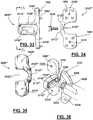
- FIG. 24is an end view of a second embodiment of the apparatus of the present invention.
- FIG. 25is a side taken along lines 25 - 25 of FIG. 24 ;
- FIG. 26is a side view of a fixture or wing part of the second embodiment of the apparatus of the present invention.
- FIG. 27is a side view taken along lines 27 - 27 of FIG. 26 ;
- FIG. 28is a side view of a third embodiment of the apparatus of the present invention.
- FIG. 29is a view taken along lines 29 - 29 of FIG. 28 ;
- FIG. 30is a view taken along lines 30 - 30 of FIG. 29 ;
- FIG. 31is a perspective view of a fourth embodiment of the apparatus of the present invention.
- FIG. 32is a perspective view of a fourth embodiment of the apparatus of the present invention.
- FIG. 33is a top view of an alternative embodiment of a second wing which is laterally adjustable relative to the first wing.
- FIG. 34is a side view of the wing of FIG. 33 .
- FIG. 35is a side view of the wing of FIG. 33 taken from the lines 35 - 35 .
- FIG. 36is a perspective view showing wing adjustment tool being connected to the second wing of FIG. 33 .
- FIG. 37is a side view showing the three pieces of wing adjustment tool.
- FIG. 38is a bottom view of the wing adjustment tool taken from the lines 38 - 38 of FIG. 37 .
- FIG. 39is a bottom view of the wing adjustment tool taken from the lines 39 - 39 of FIG. 37 .
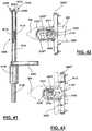
- FIG. 40is a top view of the wing adjustment tool of FIG. 37 .
- FIG. 41is a partial sectional view of the wing adjustment tool of FIG. 37 .
- FIG. 42is a top view of the wing adjustment tool of FIG. 37 connected to the second wing of FIG. 33 .
- FIG. 43shows the second wing being laterally adjusted.
- FIGS. 16 through 18are perspective views of a portion of a spinal column 30 .
- Spinal column 30includes a plurality of vertebrae 40 with spinous processes (e.g., 100 and 110 ).
- Spinal column 30also includes the spinal cord and nerve roots (not shown for clarity).
- the apparatuscan be implanted to increase the volume and/or cross sectional area of spinal canal thereby alleviating restrictions on vessels and nerves 60 associated therewith, and reducing pain caused by such restrictions.
- adjustable implant 200can be configured as shown in FIGS. 1 through 43 .
- First and second spinous processes 100 and 110are exposed using appropriate surgical techniques and thereafter, adjustable implant 200 is positioned so that upper wedging member 700 engages first spinous process 100 , and lower wedging member 900 engages second spinous process 110 (e.g., see FIG. 15,18 ).
- wedging members 700 , 900can be caused to expand respectively in the directions of arrows 702 and 902 (e.g., see FIG. 18 ) by manipulation of control screw 1500 with tool 4030 .
- Such expansionspreads apart or distracts spinous processes 100 and 110 with the beneficial effect of enlarging the volume and/or cross sectional area of the spinal canal in order to alleviate restrictions on blood vessels and nerves.
- adjustable implantcan comprise body 210 along with first and second wedging members 700 and 900 (see, e.g., FIG. 1 ).
- First and second wedging memberscan be mechanically expanded in the respective directions (and retracted in the opposite directions) of arrows 702 and 902 .
- first and second wedging members 700 and 900can be operatively connected to adjusting screw or worm gear 1200 .
- adjusting screw 1200when adjusting screw 1200 is turned in a first direction (e.g., in the direction of arrow 214 in FIG. 4 , and in the direction of arrow 1556 in FIG. 7 ) wedging members 700 and 900 expand or move respectively in the directions of arrows 702 and 902 .
- wedging members 700 and 900retract or move respectively in the opposite directions of arrows 702 and 902 .
- a controlled change in the state of expansion or retractioncan be obtained through the use of a worm gear on adjusting screw 1200 .
- FIGS. 7 and 15an expanded position of wedging members 700 and 900 is shown.
- a retracted or collapsed position of wedging members 700 , 900can be seen.
- the amount of expansion (or contraction) of wedging members 700 and 900can be controlled by adjusting screw 1200 and control screw 1500 .
- a control screw 1500can be operatively connected to adjusting member 1200 such as by a worm gear connection.
- Control screw 1500can be placed in bore 300 of body 210 (e.g., FIG. 5 where bore 300 is not threaded) and operatively connected to gear teeth or threads 1260 of adjusting screw 1200 through opening 320 of body 210 .
- adjusting screw 1200will move in the direction of arrow 214 .
- adjusting screw 1200will move in the opposite direction of arrow 214 .
- Turning of adjusting screw 1200causes wedging members 700 and 900 to move: (a) respectively in the directions of arrows 702 and 900 or (b) respectively in the opposite directions of arrows 702 and 902 , each case depending on the rotative direction of adjusting screw 1200 or gear.
- a surgeoncan control the amount of distraction caused by wedging members 700 and 900 upon a pair of spinous processes where adjustable implant 200 is placed in between.
- Such controlcan allow a surgeon to use a single adjustable implant 200 to properly distract spinous processes 100 and 110 of multiple sizes and configurations (see e.g., FIGS. 16-18 ).
- such controlled amount of distractionis not available and spinous processes 100 and 110 of different sizes or configurations require multiple sizes of distraction implants.
- prior art distraction implantsthe surgeon may not be able to tell the proper size of the prior art distraction implants required for a particular set of spinous processes 100 and 110 , and will select a first prior art implant of a first size and attempt to implant same and realize that the desired amount of distraction is not obtained (because the selected prior art implant is too small) or that too much distraction is obtained (because the selected prior art implant is too large). If the distraction amount is too small the surgeon will have to remove the selected prior art implant and select a different prior art implant (of larger size) hoping that this second implant will provide an appropriate amount of distraction. This slows down the implantation process and unnecessarily aggravates the tissue and bony area around spinous processes 100 and 110 . If the distraction amount is too large (beyond having to implant a second implant) damage may actually occur from excessive distraction.
- FIGS. 1-15show more particularly the construction of adjustable spine distraction implant 200 .
- a body/housing 210provides first 220 and second 230 end portions.
- a gear case or body 210has a dual diameter socket that includes large internally threaded bore 330 and smaller non-threaded bore 300 .
- Bore 300is receptive of control screw 1200 .
- Bore 330is receptive of threaded locking screw or nut 1600 .
- the locking screw 1600 on the upper end, and base 310 on the lower endlimits the amount of vertical movement (schematically indicated by arrow 1558 of FIG. 5 ) of control screw 1500 thus allowing control screw 1500 to rotate adjusting screw or gear 1200 and finally expand or retract wedging members 700 and 900 .
- control screw 1500can have a tool (e.g. allen wrench) receptive socket 1540 that is receptive of a tool end 5020 and external thread 1530 .
- the tool end portion 5020 of tool 5120interlocks with socket 1540 (e.g. allen wrench receptive) of threaded control screw 1500 .
- locking screw or nut 1600can have a tool (e.g. star) receptive socket 1650 that connects with tool 5030 .
- the tool end portion 5030interconnects with socket (e.g. star drive) 1650 of locking screw or nut 1600 .
- Locking screw or nut 1600can have external threads 1640 .
- Tool 5020can be used to turn control screw 1500 which in turn rotates adjusting screw 1200 which in turn expands or retracts wedging members 700 and 900 .
- Tool 5030can be used to frictionally lock control screw in place and prevent further movement of adjusting screw 1200 or wedging members 700 and 900 .
- second tool or driver 5020can be used to rotate control screw 1500 and thus rotate adjusting screw or gear 1200 in a selected direction (such as that indicated by arrow 214 in FIG. 5 , or in the opposite direction of arrow 214 ).
- adjusting screw or gear 1200can be rotatively connected to body 210 through first longitudinal bore 270 and longitudinal bore 580 .
- Second end 1220 of adjusting screw or gear 1200is supported by and rotates in longitudinal bore 580 while head 1230 rotates in and is supported by first longitudinal bore 270 .
- FIGS. 5 and 8shows one embodiment of adjusting screw 1200 being operably connected to wedging members 700 and 900 , and how control screw 1500 can be operably connected to adjusting screw 1200 thereby making control screw 1500 operably connected to wedging members 700 and 900 .
- FIG. 6is a schematic view of adjustable implant 200 where wedging members 700 and 900 are in a retracted state.
- FIG. 7is a schematic view showing wedging members 700 and 900 in a partially to completely extended or expanded state.
- FIGS. 4, 6, 7, and 18schematically show that, as adjusting screw 1200 rotates in the direction of arrow 214 (or from the opposite view in the direction of arrow 1556 shown in FIG. 7 ), wedging members 700 and 900 respectively move in the directions of arrows 702 and 902 .
- wedging members 700 and 900move respectively in the opposite directions of arrows 702 and 902 .
- middle section 1300 of adjusting screw or gear 1200can be operatively connected to arm 800 of wedging member 700 through threaded or gear toothed area 1310 cooperating with threaded arm 800 .
- Middle section 1300 of adjusting screw or gear 1200can be operatively connected to arm 1000 of wedging member 900 through threaded or gear toothed area 1320 cooperating with threaded arm 1000 .
- Such a threaded or gear toothed connectioncan be referred to as a rack and pinion type connection.
- control screw 1500can be operatively connected to adjusting screw or gear 1200 by means of threaded or gear toothed area 1260 of adjusting screw or gear 1200 .
- Such a threaded or gear toothed connectioncan be referred to as a worm gear type connection.
- Wedging members 700 and 900can be slidably connected to body 210 of adjustable implant 200 through a series of pins and tracks.
- body or gear box 210can be comprised of first end 250 and second end 252 .
- Guide 500can be connected to body 210 by first and second longitudinal arms 440 and 460 .
- First end 250can have a raised portion 370 and guide 500 on second end 252 can include a base 550 .
- raised portion 370can include track 420 and track 430 .
- base 550can include track 560 and track 570 .
- Opposed tracks 420 , 430 , 560 , and 570can form a three dimensional track system for wedging members 700 and 900 to slide back and forth in (as schematically indicated in FIGS. 6, 7, 15, and 18 .
- Adjustment screw 1200can be rotatively connected to body 210 through bore 270 in second end and bore 580 in guide 500 .
- Tip 1220can rotatively sit in bore 580 and head 1230 can rotatively sit in bore 270 .
- body 210can include a cover for head 1230 which would prevent adjusting screw 1200 from coming out of body or gear box 210 .
- a threaded or gear toothed area 1260can extend a length 1270 from top 1240 of head 1240 to a point before reaching the base 1250 , after which point non-threaded area 1230 of head 1230 will be found.
- Control screw 1500will threadably engage the threaded portion 1260 of adjustment screw 1100 , but control screw 1500 will resist longitudinal movement of adjustment screw 1200 by threads 1530 contacting the non-threaded area 1230 of adjustment screw 1200 and not allowing longitudinal movement.
- wedging members 700 and 900can be constructed substantially identical.
- Wedging member 700can be substantially identical to wedging member 900 but essentially rotated one hundred and eighty degrees so that the bottom 720 of wedging member 700 is in line with the top 910 of wedging member 900 .
- Each of the wedging members 700 , 900can respectively be provided with a gear panel or arm 800 , 1000 having a threaded or toothed rack 802 , 1002 .
- Wedging member 700has gear panel or arm 800 with toothed rack 802 .
- Wedging member or plate 900has gear panel or arm 1000 with toothed rack 1002 . Therefore, only the construction of wedging member 900 will be described in detail.
- Wedging member 900can comprise top 910 , bottom 920 , interior portion 930 , exterior portion 940 , curved portion 950 .
- Wedging member 900can also include threaded or gear toothed arm 1000 and four rails or prongs 960 , 970 , 980 , and 990 .
- wedging member 900can be slidably connected to body 210 through its rails or prongs 960 and 970 slidably connecting to slots 570 and 560 of the base 550 of guide 500 ; and through its rails or prongs 990 and 980 slidably connecting to slots 430 and 420 of raised area 370 .
- the four rails or prongs of wedging member 900can maintain a straight path for wedging member sliding in the slots of raised area 370 of body 210 , and base 550 of guide 500 .
- wedging member 700can maintain a straight path for wedging member sliding in the slots of raised area 370 of body 210 , and base 550 of guide 500 .
- the extent of expansion and retraction of wedging members 700 and 900can be controlled by threaded area 1310 cooperating with threaded arm 800 of wedging member 700 , and threaded area 1320 cooperating with threaded arm 1000 of wedging member 900 . In this manner wedging members 700 and 900 can be held in place at a selected amount of expansion or contraction (regardless of where they have been expanded or retracted to) as long as wedging members' 700 and 900 prongs remain at least partially sitting in the specified slots.
- Each wedging member 700 or 900can maintain a straight (generally vertical) path for wedging member 700 , 900 sliding in the slots 420 , 430 , 560 , and 570 .
- the extent of expansion and retraction of wedging members/plates 700 and 900can be controlled by screw/gear 1200 .
- plates/wedging members 700 and 900can be held in place at a selected amount of expansion or contraction (regardless of where they have been expanded or retracted to) as long as wedging members' 700 and 900 rails 760 , 770 , 780 , 790 (for wedging member 700 ) and rails 960 , 970 , 980 , and 990 (for wedging member 900 ) remain at least partially sitting in the specified slots.
- the radial extent of threading for threaded areas 1310 and 1320can be selected by having non-threaded areas 1330 and 1340 . That is when the radial extent of the threaded area is reached, the specific wedging member ( 700 and/or 900 ) will stop its expansion.
- a second safe guardcan be provided in the amount of radial threading 1260 for the worm gear portion of adjusting screw 1200 .
- an angular amount 1280 of about 120 degrees of radial threading 1260can be provided which will restrict further rotation of screw 1200 when the threads angularly reach point 1262 or 1264 (see FIG. 5 ).
- arms 440 and 460can include notches 450 , 452 , 470 , and 472 to accommodate the rails or prongs of wedging members 700 and 900 , and allow complete retraction of wedging members 700 and 900 . Without these notches the prongs of wedging members 700 and 900 would prevent complete retraction.
- FIG. 11is a perspective view of adjustable implant 200 placed on its side.
- wedging members 700 and 900are completely retracted and their exterior surfaces 740 and 940 are flush with raised area 370 of second end 230 and base 550 of guide 500 . Making the exterior surfaces flush when wedging members 700 and 900 are fully retracted resists damage to bone and tissue during the initial insertion process (as no sharp edges are seen).
- control screw 1500can be locked in place by locking screw 1600 .
- Locking screw 1600can include first end 1610 , second end 1620 , and threaded area 1640 .
- Locking screw 1600can have bore 1650 which allows access to control screw 1500 even when locking screw 1600 is connected to the bore 330 for locking screw 1600 .
- Bore 1650allows locking screw to be in place even when adjusting control screw 1500 . This feature reduces the amount of free parts the surgeon must keep track of during the operation (and prevents control screw 1500 and locking screw 1600 from falling out during an implantation procedure).
- a cover for bore 330can be provided which prevents locking screw 1600 from being completely removed from body 210 .
- control screw 1500is locked in place by second end 1620 of locking screw 1600 squeezing control screw 1500 against base 210 of bore 300 .
- This squeezingfrictionally locks in place control screw 1500 .
- Even if not frictionally locked by locking screw 1600the status of being a worm gear connection between control screw 1500 and threads 1260 of adjustment screw 1200 , would tend to be self locking.
- vibrations and other movements of implant 200 over timemay tend to cause adjustment screw 1200 to rotate and cause unwanted movement of wedging members 700 and 900 .
- first end 1610is flush with top 232 of body 210 .
- Adjustable implant 200 and its componentscan be made of a number of materials, including but not limited to, stainless steel, titanium, ceramics, plastics, elastics, composite materials or any combination of the above.
- the modulus of elasticity of the implantcan be matched to that of bone, so that the implant is not too rigid.
- the flexibility of the implantcan further be enhanced by providing additional apertures or perforations throughout the implant.
- adjustable implantprovides for distraction in the range of about 8 mm to about 11 mm in one embodiment (more preferably about 8 mm to about 10.7 mm), and in another embodiment in the rage of about 10 mm to about 15 mm (more preferably about 10.5 mm to about 14 mm).
- an implantation guide 500can be provided. Positioned at the other end of body 210 can be guide 500 .
- Guide 500can be triangularly shaped so as to be a pointed and arrow shaped guide.
- guide 500can be in the shape of a cone with lateral truncated sides along the longitudinal axis wedging members 700 and 900 .
- Guide 500can include a threaded bore 590 .
- guide 500can be bulbous, cone shaped, pointed, arrow shaped, and the like, in order to assist in the insertion of adjustable implant 200 between adjacent spinous processes.
- the insertion techniquedisturbs as little of the bone and surrounding tissue or ligaments as possible in order to (a) reduce trauma to the site and facilitate early healing, and (b) not destabilize the normal anatomy.
- guide 500has a cross section which is adjacent to the cross section of completely retracted wedging members 700 and 900 and of similar shape. Where guide 500 and completely retracted wedging members 700 and 900 have elliptical cross sections, preferably the major dimension of guide's 500 cross section is about equal to the major dimension of completely retracted wedging members 700 and 900 cross section, and guide's 500 minor dimension about equal to completely retracted wedging members 700 and 900 cross section.
- guide 500can extend from body 210 of implant 200 with a cross section which reduces in size in a direction away from body 210 .
- guide 500can be cone shaped with a base located adjacent wedging members 700 and 900 . Further, in one embodiment guide 500 can have a base cross section about the same as an oval cross section of completely retracted wedging members 700 and 900 .
- guide 500has faces 520 and 530 which are at about 45 degree angles (other angles, such as by way of example only, from about 30 degrees to about 60 degrees, and from about 25 to about 75 degrees are also envisioned), with a tip 540 so that adjustable implant 200 can be more easily urged between the spinous processes.
- adjustable implantcan have a central body portion, the central body portion including wedging members 700 and 900 , with a longitudinal axis 212 . Extending from the central body portion can be a first wing 1800 and second wing 2000 which can be substantially perpendicular to longitudinal axis 212 . Wings 1800 and 2000 can resist the tendency of adjustable implant to slide out from between spinous processes 100 and 110 . In one embodiment second wing 2000 can detachably connectable to adjustable implant 200 . In one embodiment second wing 2000 can be laterally adjustable relative to first wing 1800 to accommodate spinous processes of varying sizes and dimensions arrows 2002 and 2004 in FIG. 17 schematically indicate lateral adjustment of second wing 2000 . Making wing 2000 detachably connectable facilitates insertion of adjustable implant between spinous processes 100 and 110 , such as through guide 500 .
- completely retracted wedging members 700 and 900can have an elliptical cross section with a major axis which is substantially perpendicular to a major dimension (e.g., longitudinal axis) of first wing 1800 along longitudinal axis. Making these two axes substantially perpendicular facilitates proper positioning of adjustable implant 200 between selected spinous processes 100 and 110 , and ensuring that substantial portions of wedging members 700 and 900 come in contact with both the upper and lower spinous processes so that the reaction loads can be more evenly distributed on the spinous processes by wedging members 700 and 900 during implantation and subsequent spinal column movements after implantation.
- first wing 1800can include an upper area 1830 and a lower area 1840 .
- Upper areacan include a rounded end 1832 .
- Rounded end 1832can be designed to accommodate the anatomical form or contour various portions of the vertebrae, for example L4 (for a L4 L5 placement) or L5 (for a L5 S1 placement) superior lamina of the vertebra. It is to be understood that the same shape or variations of this shape can be used to accommodate other lamina of any vertebra.
- the lower portion 1842can also be rounded in order to accommodate the vertebrae.
- guide 500can include a threaded bore 590 which accepts a screw 2130 in order to hold a second wing 2000 in position. With the second wing 2000 in position, the screw 2130 when it is positioned in the threaded bore 590 can engage and hold second wing 2000 in position relative to first wing 1800 .
- First and second wings 1800 and 2000can come in a variety of shapes in order to provide for variations in the anatomical form of the spinous processes. Such shapes can be as depicted in FIGS. 103, 104, 105, 106, and 107 of U.S. Pat. No. 7,101,375.
- the winghas an upper portion and a lower portion.
- the lower portionis thicker than the upper portion in order to accommodate the spinous process, where the lower spinous process is thinner than the upper spinous process.
- both the upper and lower portionsare enlarged over the upper and lower portions of FIG. 103 to accommodate both the upper and lower spinous processes being smaller.
- FIGS. 106 and 107Alternative embodiments of second wings 2000 , as shown in FIGS. 104 and 105, are depicted in FIGS. 106 and 107.
- the second wingaccommodates the same anatomical shape and size of the spinous processes as does the second wing in FIGS. 104 and 105 respectively.
- substantial masseshave been removed from the wings.
- the upper and lower portionsare essentially formed or bent in order to extend from the central portion of the second wing.
- FIGS. 12 and 13are views of second wing 2000 and connecting screw 2130 .
- Connecting screw 2130can comprise threaded area 2140 and reduced cross sectional area 2150 .
- Reduced cross sectional area 2150can allow second wing member 2000 to slide (and be longitudinally adjustable) relative to screw 2130 (and first wing member 1800 ).
- Second wing member 2000can include track 2110 and track can include threaded area 2120 .
- Second wing member 2000can include first end 2010 , second end 2020 , and cutout area 2050 .
- Cutout area 2050can be shaped to fit around the outer surface of guide 500 . Alternatively, cutout area 2050 can be enlarged to allow full distraction of wedging members 700 and 900 (see e.g., FIG. 35 with second wing 2000 and cutout area 2050 ).
- FIG. 15is a perspective view of adjustable implant 200 having first and second wedging members 700 and 900 extended in the directions of arrows 702 and 902 and control screw 1500 being turned in the direction of arrow 4032 , causing adjusting screw or gear 1200 to turn in the direction of arrow 214 along longitudinal centerline 212 .
- FIG. 17is a perspective view of adjustable implant 200 placed in between spinous processes 110 and 120 .
- a longitudinal line 2008 through second wing 2000will be parallel to a longitudinal line 1808 going through first wing 1800 .
- Arrows 2002 and 2004schematically indicate the adjustability of second wing 2000 relative to first wing 1800 by varying the distance D.
- FIG. 18is a side perspective view of adjustable implant 200 showing a tool 4030 being used on the control screw 1500 to adjust adjusting screw 1500 and change the state of first 700 and second 900 wedging members.
- line 212which is the axis of rotation of adjusting screw or gear 1200
- line 218which is perpendicular to the axis of rotation of control screw 1500 (schematically indicated by arrow 4032 ).
- line 218can be spaced apart by the distance A from the axis of rotation of control screw 1500 .
- the axis of rotation of control screw 1500does not intersect the axis of rotation of adjusting screw or gear 1200 .
- Adjustable implant 200can be positioned adjacent to upper and lower vertebrae 120 and 130 . Extending upwardly from vertebrae 120 and 130 are the upper and lower spinous processes 100 and 110 . In a preferred embodiment, the fit of adjustable implant 200 between spinous processes 100 and 110 can be such that wings 1800 and 2000 do not touch spinous processes 100 and 110 . One advantage of wings 1800 and 2000 is that they resist dislodgment of adjustable implant 200 from between spinous processes 100 and 110 .
- first and second wedging members 700 and 900 of adjustable implant 200are urged between spinous processes 100 and 110 .
- second wing 2000can be guided by the other sides of the spinous processes from a path which causes the plane of second wing 2000 to move substantially parallel to the plane of first wing 1800 until screw 2130 can be placed in threaded bore 590 of guide 500 .
- Bolt 2130can be tightened to secure second wing 2000 .
- a second wing 2000is not used where it was deemed impractical or unnecessary to use a second wing 2000 .
- neither a first 1800 nor a second 2000 wingis used where the anatomy between the spinous processes 100 and 110 was such that it would be undesirable to use either a first or second wing.
- the spinous processes 100 and 110can be accessed and distracted initially using appropriate instrumentation, and adjustable implant 200 can be inserted and adjusted in order to maintain and achieve the desired distraction.
- the spinous processcan be accessed and adjustable implant 200 appropriately positioned. Once positioned, implant 200 can be expanded in order to distract the spinous processes or extend the distraction of already distracted spinous processes. Accordingly, adjustable implant 200 can be used to create or increase a previously created distraction, or to maintain a distraction which has already been created.
- FIGS. 19-23show an instrument or tool 5000 that can be used to rotate either the control screw 1500 and/or the locking screw/nut 1600 and adjust adjustable implant 200 .
- Tool 5000can include body 5010 , shaft 5014 , control screw head 5020 , locking screw head 5030 , driver 5120 , driver 5130 , counter torque handle 5200 , base 5300 , and set prongs 5310 , 5320 .
- Torque handle 5200can be connected to body 5010 and enables a surgeon to hold and support the tool/instrument 5000 .
- Driver 5130can be slidingly and rotatively connected to body 5010 .
- Driver 5130can include locking screw head 5030 .
- Driver 5120can be slidingly and rotatively connected to driver 5130 .
- Driver 5120can include control screw head 5020 .
- Driver 5130can be connected to shaft 5134 which itself is connected to locking screw head 5030 .
- Base 5300can be connected to body 5010 and include two set prongs 5310 and 5320 .
- Set prongs 5310 and 5320can locate or set tool 5000 relative to body 210 of adjustable implant 200 by matching set prongs 5310 and 5320 with openings 5310 and 5320 .
- the individual drivers 5120 and 5130can be used to drive control screw head 5020 and locking screw head 5030 which respectively will turn control screw 1500 and locking screw 1600 .
- Arrows 5121 and 5122schematically indicate slidable movement of driver 5120 .
- Arrow 5017schematically indicates rotation of driver 5120 (which can also be in the opposite direction).
- Tool 5000is a preferred tool in that it allows both control screw 1500 and locking screw 1600 to be manipulated with a single instrument. Additionally, it can optionally have a placement system (body 5300 and prongs 5310 and 5320 ). Body 5300 can be a distal flange or bracket that carries one or more projections or prongs 5310 and 5320 . If the optional body 5300 is employed, the gear case or body 210 carries sockets 5310 and 5320 that are sized and shaped correspondingly to projections 5310 and 5320 . In this fashion, the surgeon can interlock the projections 5310 and 5320 with the sockets 5310 and 5320 ′ to help rigidify the connection of the tool or instrument 5000 to the body or gear case 210 when an adjustment of either of the screws 1500 or 1600 is required.
- FIGS. 24-27show another embodiment of the apparatus of the present invention, designated by the numeral 200 A.
- the embodiment of FIGS. 24-27is basically the same as the embodiment of FIGS. 1-23 .
- the first and second fixtures or wings 1800 , 2000are respectively provided with prongs or projections or spikes 1872 , 1882 which enhance gripping of the spine 30 (and spinous processes 100 and 110 ).
- FIGS. 28-30show another embodiment of the apparatus of the present invention, designated generally by the numeral 200 B.
- the implant 200 Bis similar in construction to the embodiment of FIGS. 1-23 with the exception of the shape of the wings 1800 , 2000 being generally rectangular, but also providing rounded or curved end portions.
- the first wing 1800provides upper and lower rounded or curved end portions 1830 , 1840 .
- the second wing or fixture 2000provides upper and lower rounded or curved end portions 2030 , 2040 .
- the second fixture or wing 2000 ′′provides a concavity 2050 that is receptive of body 210 .
- a fastener 2130enables attachment of second fixture or wing 2000 to body 210 using fastener 2130 with a track/slot 2110 as with the embodiment shown in FIG. 13 .
- concavity 2050can be expanded to allow wedging members 700 and 900 to be fully distracted even where second wing 2000 is placed over wedging members 700 and 900 .
- FIGS. 31-32show yet another embodiment, designated generally by the numeral 200 C.
- Adjustable implant 200 Cprovides the same basic construction of the embodiment of FIGS. 1-18 with the addition of a flexible sleeve 2500 that is placed over the body 210 (and wedging members 700 and 900 ) as shown in FIGS. 31 and 32 .
- the sleeve 2500has a hollow bore or open ended cavity 2510 that enables the sleeve 2500 to occupy a position on body 210 , basically covering wedging members 700 an 900 , when the wedging members/plates 700 and 900 are expanded or retracted, the sleeve acts as an interface or cushion in between the wedging members 700 and 900 and the surrounding tissue. This can prevent pinching, tearing, or damage to the surrounding tissue.
- FIGS. 33 through 43show one embodiment for laterally adjusting the second wing relative to the first wing with another embodiment of second wing 2000 .
- FIGS. 36-43show an instrument or tool 6000 that can be used to slidingly adjust/clamp second wing 2000 relative to first wing 1800 of various adjustable implants.
- Tool 6000can include body 6010 , shaft 6014 , wing fastener screw head 6020 , sliding adjuster screw head 6030 , driver 6120 , driver 6130 , counter torque handle 6200 , base 6300 , and set prongs 6310 , 6320 .
- Torque handle 6200can be connected to body 6010 and enables a surgeon to hold and support the tool/instrument 6000 .
- Driver 6130can be slidingly and rotatively connected to body 6010 .
- Driver 6130can include sliding adjuster screw head 6030 .
- Driver 6120can be slidingly and rotatively connected to driver 6130 .
- Driver 6120can include fastener screw head 6020 .
- Base 6300can be connected to body 6010 and include two set prongs 6310 and 6320 .
- Set prongs 6310 and 6320can locate or set tool 6000 relative to second wing 2000 of adjustable implant 200 by matching set prongs 6310 and 6320 with openings 6310 and 6320 .
- Once set the individual driver 6130can be used to slidingly adjust second wing 2000 relative to first wing (for a clamping effect) of adjustable implant 200 .
- driver 6120can be used to lock fastener 2130 with control screw head 6020 .
- Body 6300can be a distal flange or bracket that carries one or more projections or prongs 6310 and 6320 . If the optional body 6300 is employed, the second wing 2000 carries sockets 6310 and 6320 that are sized and shaped correspondingly to projections 6310 and 6320 .
- second wing 2000will slide along adjustable implant via opening 2050 sliding over adjustable implant.
- the amount of adjustment of second wing 2000is limited so that this wing does not travel over wedge members 700 and/or 900 .
- Projections or prongs 1882help stabilize adjustable implant relative to the spinal processes.
- opening 2050can be enlarged to allow full expansion/distraction of wedging members 700 and 900 even where second wing 2000 is adjusted over wedging members 700 and 900 .
- adjustable implant 200can act as an extension stop.
- adjustable implantcan resist or stop further extension between spinous processes 100 and 110 once the back has been bent backwardly such that adjustable implant 200 stops further movement of adjacent spinous processes 100 and 110 towards each other.
- the distance between wedging members 700 and 900can stop movement spinous processes 100 and 110 toward each other.
- Adjustable implant 200does not limit the flexion of spinal column 30 (because in flexion spinal column 30 is bent forwardly and spinous processes 100 and 110 move away from each other (and away from wedging members 700 and 900 ).
- wedging member 700In one embodiment only one wedging member 700 is provided.
- wedging member 900can be permanently attached to body 210 (and arm 100 either removed entirely or the threading removed). In this embodiment wedging member can expand or retract based on movement of adjustment screw 1200 . In this embodiment about one half of the adjusting expansion or distraction capability will be available compared to embodiment where two wedging members 700 and 900 are provided.
- wedging members 700 and 900can be adjusted to compensate for forming an elliptical cross section when completely retracted.
- a capcan be placed over first longitudinal bore 270 which also will prevent adjusting screw 1200 from leaving first longitudinal bore 270 .
- This capcan also prevent adjustable implant 200 from being disassembled after manufacture which can prevent improper reassembly.
- This capcan be laser welded to body 210 .
- one or more timing markscan be placed on adjusting screw 1200 (e.g., its head 1230 ) and body 210 which marks can show proper alignment of adjusting screw 1200 relative to body 210 (ensuring proper installation of the components).
- first wing 1800can limit the expansion of wedging members 700 and/or 900 .
- raised areas or detentscan act as an additional factor of safety beyond the various amounts of threading on adjusting screw 1200 (middle section 1300 and head 1230 ).
- wedging members 700 and 900have a flat, irregular, or concave shape.
- adjustable implant 200can be implanted essentially floating in position in order to gain the benefits of extension stop and not limiting flexion.
- the spinous processescan be accessed and distracted initially using appropriate instrumentation, and adjustable implant 200 can be inserted and adjusted in order to maintain and achieve the desired distraction.
- the spinous processcan be accessed and adjustable implant 200 appropriately positioned. Once positioned, implant 200 can be expanded in order to distract the spinous processes or extend the distraction of already distracted spinous processes. Accordingly, adjustable implant 200 can be used to create or increase a previously created distraction, or to maintain a distraction which has already been created.
- adjustable implant 200would be placed close to the instantaneous axis of rotation of spinal column 30 so that the reaction forces adjustable implant places on spinal column 30 are minimized.
- adjustable implant 200For purposes of surgical implantation of adjustable implant 200 into a patient, the patient is preferably positioned on his side and placed in a flexed (tucked) position in order to distract the upper and lower vertebrae.
- a small incisionis made on the midline of the spinous processes.
- the spinous processesare spread apart or distracted with a spreader.
- the incisionis spread downwardly toward the table, and adjustable implant 200 is preferably inserted upwardly between the spinous processes 100 and 110 in a manner that maintains the distraction of spinous processes.
- the adjustable implant 200is urged upwardly until guide 500 and at least part of wedging member 700 and/or 900 are visible on the other side of the spinous process. Once this is visible, the incision is spread upwardly away from the table and the retaining unit or second wing 2000 can be attached via screw 2130 .
- Track 2110can be used to space second wing 2000 relative to first wing 1800 (at least to the extent of allowable movement through slot 2110 ). After this had occurred, the incisions can be closed.
- An alternative surgical approachrequires that small incisions be made on either side of the space located between the spinous processes.
- the spinous processesare spread apart or distracted using a spreader placed through the upper incision.
- adjustable implant 200can be inserted upwardly between spinous processes 100 and 110 in a manner that urges the spinous processes apart.
- Adjustable implant 200can be urged upwardly until guide 500 and at least part of wedging member 700 and/or 900 are visible through the second small incision in the patient's back. Once this is visible, second wing 2000 can be attached to guide 500 through screw 2130 . After this has occurred, the incisions can be closed.
- the advantage of the above two surgical proceduresis that a surgeon is able to observe the entire operation, where he can look directly down onto the spinous processes as opposed to having to view the procedure from positions which are to the right and to the left of the spinous processes.
- the incisionis as small as possible and the surgeon is working in a bloody and slippery environment.
- an implant that can be positioned directly in front of a surgeonis easier to insert and assemble than an implant which requires the surgeon to shift from side to side.
- a top down approach, as an approach along a position to anterior lineis preferred so that all aspects of the implantation procedure are fully visible to the surgeon at all times. This aides in the efficient location of (i) the adjustable implant 200 between the spinous processes, (ii) the retaining second wing 2000 in adjustable implant 200 , and (iii) finally screw 2130 in adjustable implant 200 .
- the methodcan include implanting adjustable implant 200 between two spinous processes 100 and 110 , expanding adjustable implant 200 a first amount, allowing spine 30 to creep or adjust to this first amount of distraction, and then expanding adjustable implant 200 a second amount, and then allowing a period of time spine 30 to creep or adjust to this new level of distraction. This process could be repeated until the desired amount of overall distraction has been accomplished.
- This stepped wise (and wait) distraction methodcan be used with insertion tools prior to the installation of adjustable implant 200 . The tools can be used to obtain the desired distraction using a series of spinal distraction and spinal creep periods before firs implanting adjustable implant 200 .
- One embodimentuses a dilator tool 4010 and a distractor tool 4020 .
- the patientcan be placed prone or lateral.
- a skin incisioncan be made over spinous processes 100 and 110 where the stenosis exists.
- the musclewill be moved off of the spinous process to the base bilaterally. If the facet joint is too large, the top can be removed to facilitate placement of adjustable implant 200 at the base of spinous process 110 .
- the inter spinous ligamentis left intact.
- a small dilator 4010can be placed through the inter spinous ligament near the base.
- a second distracter 4020is then used to open the space up to accommodate the smaller adjustable implant 200 .
- Adjustable implantis then adjusted causing wedging members 700 and 900 to expand a desired amount in the direction of arrows 702 and 902 .
- Adjustmentis obtained by rotation of a control screw 1500 which rotates an adjustment screw or worm gear 1200 . During this expansion process the surgeon can feel the inter spinous ligament. Once taught, adjustable implant 200 can be allowed to sit and settle for a period of time (such as for five minutes). After this settling period of time, control screw 1500 can be tightened a bit more causing wedging members 700 and 900 to expand a bit more and ensure that the inter spinous ligament remains taught. If adjustable implant 200 cannot be expanded to a point where there is the desired amount of stretching of the inter spinous ligament, then a larger sized adjustable implant 200 can be used and adjusted accordingly. Adjustable implant allows the attachment of a second wing 2000 to prevent lateral dislodgment of adjustable implant from spinous processes 100 and 110 .
- the areais irrigated with antibiotics and saline and the muscle is injected with local anesthetic and the wound is closed.
- FIGS. 16 through 18show various steps in one embodiment of the method of implanting adjustable implant 200 .
- FIG. 16is a perspective view of a portion of a spinal column 30 where adjustable implant 200 is being inserted between a first spinous process 100 and a second spinous process 110 (guide 500 facilitates such insertion).
- FIG. 17shows adjustable implant 200 being more fully inserted between a first spinous process 100 and a second spinous process 110 and second wing 2000 being attached.
- FIG. 18shows adjustable implant 200 after first 700 and second 900 wedging members have been extended more fully (in the directions of arrows 702 and 902 ) pushing apart first spinous process 100 and second spinous process 110 .
- the embodimentscan be used to relieve pain caused by spinal stenosis in the form of such as that caused by central canal stenosis or foraminal (lateral) stenosis.
- Various embodimentshave the ability to flatten the natural curvature of the spine and open the neural foramen and the spacing between adjacent vertebra to relieve problems associated with the above mentioned lateral and central stenosis.
- various embodimentscan be used to relieve pain associated with facet arthropathy.
- Various embodimentcan be implanted with surgery that is minimally invasive and can be used on an outpatient basis.
Landscapes
- Health & Medical Sciences (AREA)
- Orthopedic Medicine & Surgery (AREA)
- Neurology (AREA)
- Life Sciences & Earth Sciences (AREA)
- Surgery (AREA)
- Heart & Thoracic Surgery (AREA)
- Engineering & Computer Science (AREA)
- Biomedical Technology (AREA)
- Nuclear Medicine, Radiotherapy & Molecular Imaging (AREA)
- Medical Informatics (AREA)
- Molecular Biology (AREA)
- Animal Behavior & Ethology (AREA)
- General Health & Medical Sciences (AREA)
- Public Health (AREA)
- Veterinary Medicine (AREA)
- Prostheses (AREA)
- Surgical Instruments (AREA)
Abstract
Description
| LIST FOR REFERENCE NUMERALS |
| (Part No.) | (Description) | ||
| Reference Numeral | Description | ||
| 10 | patient | ||
| 20 | back | ||
| 30 | spinal column | ||
| 40 | vertebrae | ||
| 50 | vertebra | ||
| 60 | nerves | ||
| 70 | blood vessels | ||
| 100 | first spinous process | ||
| 110 | second spinous process | ||
| 120 | upper vertebra | ||
| 122 | arrow | ||
| 130 | lower vertebra | ||
| 132 | arrow | ||
| 200 | implant | ||
| 202 | arrow | ||
| 210 | body | ||
| 212 | longitudinal axis | ||
| 214 | arrow | ||
| 215 | arrow | ||
| 216 | plane | ||
| 218 | line | ||
| 220 | first end | ||
| 230 | second end | ||
| 232 | top | ||
| 240 | housing | ||
| 250 | first end of housing | ||
| 252 | second end of housing | ||
| 260 | width of first end | ||
| 270 | first longitudinal bore | ||
| 280 | base | ||
| 290 | second longitudinal bore | ||
| 300 | control screw bore | ||
| 310 | base of control screw bore | ||
| 320 | opening between control screw | ||
| bore and first longitudinal bore | |||
| 330 | locking screw bore | ||
| 340 | threaded area | ||
| 350 | base of locking screw bore | ||
| 360 | second end of housing | ||
| 370 | raised portion | ||
| 380 | first side of raised portion | ||
| 390 | shape | ||
| 400 | second side of raised portion | ||
| 410 | shape | ||
| 420 | first track | ||
| 430 | second track | ||
| 440 | first longitudinal arm | ||
| 450 | notch | ||
| 452 | notch | ||
| 460 | second longitudinal arm | ||
| 470 | notch | ||
| 472 | notch | ||
| 500 | insertion guide | ||
| 510 | arrow head | ||
| 520 | first face | ||
| 530 | second face | ||
| 540 | tip | ||
| 550 | base | ||
| 560 | first track | ||
| 570 | second track | ||
| 580 | longitudinal bore | ||
| 590 | threaded bore for second wing | ||
| 600 | distracting unit | ||
| 610 | central body | ||
| 620 | spacer | ||
| 630 | cross section | ||
| 640 | ellipse | ||
| 650 | major axis | ||
| 660 | minor axis | ||
| 670 | longitudinal axis | ||
| 700 | first wedging member | ||
| 702 | arrow | ||
| 710 | top | ||
| 720 | bottom | ||
| 730 | interior portion | ||
| 740 | exterior portion | ||
| 742 | outermost point of exterior | ||
| 750 | curved portion | ||
| 760 | first prong | ||
| 770 | second prong | ||
| 780 | third prong | ||
| 790 | fourth prong | ||
| 800 | threaded arm | ||
| 802 | geared or toothed area | ||
| 810 | tip of threaded arm | ||
| 820 | shape of tip | ||
| 830 | length of threaded arm | ||
| 900 | second wedging member | ||
| 902 | arrow | ||
| 910 | top | ||
| 920 | bottom | ||
| 930 | interior portion | ||
| 940 | exterior portion | ||
| 942 | outermost point of exterior | ||
| 950 | curved portion | ||
| 960 | first prong | ||
| 970 | second prong | ||
| 980 | third prong | ||
| 990 | fourth prong | ||
| 1000 | threaded arm | ||
| 1002 | geared or toothed area | ||
| 1010 | tip of threaded arm | ||
| 1020 | shape of tip | ||
| 1030 | length of threaded arm | ||
| 1200 | adjusting screw or worm gear | ||
| 1210 | first end | ||
| 1220 | second end | ||
| 1230 | head | ||
| 1240 | top of head | ||
| 1250 | base of head | ||
| 1260 | threaded area | ||
| 1262 | end of threaded area | ||
| 1264 | end of threaded area | ||
| 1270 | length of threads from top to base of head | ||
| 1280 | angular extent of threaded area | ||
| 1300 | middle section | ||
| 1310 | first threaded area | ||
| 1320 | second threaded area | ||
| 1330 | first non-threaded area | ||
| 1340 | second non-threaded area | ||
| 1360 | tip | ||
| 1500 | control screw | ||
| 1510 | first end | ||
| 1520 | second end | ||
| 1530 | threaded area | ||
| 1540 | receiving area for adjusting tool | ||
| 1550 | arrow | ||
| 1554 | arrow | ||
| 1556 | arrow | ||
| 1558 | arrow | ||
| 1600 | locking screw | ||
| 1610 | first end | ||
| 1620 | second end | ||
| 1630 | reduced area of second end or tip | ||
| 1640 | threaded area | ||
| 1650 | receiving area for adjusting tool | ||
| 1800 | first wing | ||
| 1830 | upper area | ||
| 1832 | rounded area | ||
| 1840 | lower area | ||
| 1842 | rounded area | ||
| 1872 | plurality of spikes or proj ections | ||
| 1882 | plurality of spikes or projections | ||
| 2000 | second wing | ||
| 2002 | arrow | ||
| 2004 | arrow | ||
| 2010 | first end | ||
| 2020 | second end | ||
| 2030 | upper area | ||
| 2040 | lower area | ||
| 2050 | cutout area | ||
| 2060 | first side | ||
| 2070 | second side | ||
| 2080 | middle section | ||
| 2090 | base of middle section | ||
| 2100 | curved area of base | ||
| 2110 | track | ||
| 2120 | threaded area | ||
| 2130 | connecting screw | ||
| 2140 | threaded area | ||
| 2150 | reduced cross sectional area | ||
| 2160 | receiving area for adjusting tool | ||
| 2500 | flexible sleeve member | ||
| 2510 | opening or bore | ||
| 3000 | first distraction amount | ||
| 3010 | second distraction amount | ||
| 3020 | extension stop | ||
| 4000 | instrumentation | ||
| 4010 | dilator tool | ||
| 4020 | distractor tool. | ||
| 4030 | |||
| 4032 | |||
| 4040 | |||
| 4042 | |||
| 5000 | |||
| 5010 | |||
| 5014 | |||
| 5015 | |||
| 5016 | |||
| 5017 | |||
| 5020 | |||
| 5030 | locking | ||
| 5120 | driver | ||
| 5121 | arrow | ||
| 5122 | |||
| 5123 | |||
| 5130 | |||
| 5134 | |||
| 5200 | |||
| 5300 | |||
| 5310 | |||
| 5320 | |||
| 6000 | |||
| 6010 | |||
| 6014 | shaft | ||
| 6015 | arrow | ||
| 6016 | |||
| 6017 | |||
| 6018 | |||
| 6020 | locking | ||
| 6030 | adjustable | ||
| 6120 | driver | ||
| 6121 | arrow | ||
| 6122 | |||
| 6123 | |||
| 6130 | |||
| 6200 | |||
| 6300 | |||
| 6310 | |||
| 6320 | set prong | ||
Claims (17)
Priority Applications (1)
| Application Number | Priority Date | Filing Date | Title |
|---|---|---|---|
| US15/200,459US10543024B2 (en) | 2007-04-10 | 2016-07-01 | Adjustable spine distraction implant |
Applications Claiming Priority (4)
| Application Number | Priority Date | Filing Date | Title |
|---|---|---|---|
| US91100307P | 2007-04-10 | 2007-04-10 | |
| US12/100,718US8231656B2 (en) | 2007-04-10 | 2008-04-10 | Adjustable spine distraction implant |
| US13/562,037US9381050B2 (en) | 2007-04-10 | 2012-07-30 | Adjustable spine distraction implant |
| US15/200,459US10543024B2 (en) | 2007-04-10 | 2016-07-01 | Adjustable spine distraction implant |
Related Parent Applications (1)
| Application Number | Title | Priority Date | Filing Date |
|---|---|---|---|
| US13/562,037ContinuationUS9381050B2 (en) | 2007-04-10 | 2012-07-30 | Adjustable spine distraction implant |
Publications (2)
| Publication Number | Publication Date |
|---|---|
| US20170027618A1 US20170027618A1 (en) | 2017-02-02 |
| US10543024B2true US10543024B2 (en) | 2020-01-28 |
Family
ID=39831586
Family Applications (3)
| Application Number | Title | Priority Date | Filing Date |
|---|---|---|---|
| US12/100,718Active2030-01-10US8231656B2 (en) | 2007-04-10 | 2008-04-10 | Adjustable spine distraction implant |
| US13/562,037Active2028-06-27US9381050B2 (en) | 2007-04-10 | 2012-07-30 | Adjustable spine distraction implant |
| US15/200,459Active2028-10-28US10543024B2 (en) | 2007-04-10 | 2016-07-01 | Adjustable spine distraction implant |
Family Applications Before (2)
| Application Number | Title | Priority Date | Filing Date |
|---|---|---|---|
| US12/100,718Active2030-01-10US8231656B2 (en) | 2007-04-10 | 2008-04-10 | Adjustable spine distraction implant |
| US13/562,037Active2028-06-27US9381050B2 (en) | 2007-04-10 | 2012-07-30 | Adjustable spine distraction implant |
Country Status (2)
| Country | Link |
|---|---|
| US (3) | US8231656B2 (en) |
| WO (1) | WO2008124831A2 (en) |
Cited By (6)
| Publication number | Priority date | Publication date | Assignee | Title |
|---|---|---|---|---|
| US10722380B1 (en)* | 2019-02-04 | 2020-07-28 | Bret Michael Berry | Laterally expandable spinal implant |
| US11432937B1 (en) | 2021-11-02 | 2022-09-06 | Linares Medical Devices, Llc | Expandable spinal jack for installation between upper and lower succeeding superior articular processes |
| US20220287752A1 (en)* | 2020-09-02 | 2022-09-15 | Curiteva, Inc. | Expandable laminoplasty device |
| US20230136415A1 (en)* | 2021-11-02 | 2023-05-04 | Linares Medical Devices, Llc | Expandable spinal jack for installation between upper and lower succeeding superior articular processes |
| US12011360B2 (en) | 2021-10-22 | 2024-06-18 | Linares Spinal Devices, Llc | Expandable spinal jack for installation between upper and lower succeeding superior articular processes |
| US12232790B2 (en) | 2022-12-30 | 2025-02-25 | IvyTech Design LLC | Adjustable angle orthopedic distractor, compressor, and distractor-compressor |
Families Citing this family (100)
| Publication number | Priority date | Publication date | Assignee | Title |
|---|---|---|---|---|
| US6907884B2 (en) | 2002-09-30 | 2005-06-21 | Depay Acromed, Inc. | Method of straddling an intraosseous nerve |
| US7258690B2 (en) | 2003-03-28 | 2007-08-21 | Relievant Medsystems, Inc. | Windowed thermal ablation probe |
| US8361067B2 (en) | 2002-09-30 | 2013-01-29 | Relievant Medsystems, Inc. | Methods of therapeutically heating a vertebral body to treat back pain |
| US9055981B2 (en)* | 2004-10-25 | 2015-06-16 | Lanx, Inc. | Spinal implants and methods |
| US8241330B2 (en) | 2007-01-11 | 2012-08-14 | Lanx, Inc. | Spinous process implants and associated methods |
| WO2006058221A2 (en) | 2004-11-24 | 2006-06-01 | Abdou Samy M | Devices and methods for inter-vertebral orthopedic device placement |
| US9801733B2 (en) | 2005-03-31 | 2017-10-31 | Life Spine, Inc. | Expandable spinal interbody and intravertebral body devices |
| US9034041B2 (en) | 2005-03-31 | 2015-05-19 | Life Spine, Inc. | Expandable spinal interbody and intravertebral body devices |
| US8940048B2 (en) | 2005-03-31 | 2015-01-27 | Life Spine, Inc. | Expandable spinal interbody and intravertebral body devices |
| US7731751B2 (en)* | 2005-03-31 | 2010-06-08 | Life Spine, Inc. | Expandable spinal devices and method of insertion |
| US8500778B2 (en)* | 2006-02-01 | 2013-08-06 | DePuy Synthes Products, LLC | Interspinous process spacer |
| US8790403B2 (en)* | 2006-04-20 | 2014-07-29 | K2M, Inc. | Monorail system |
| US8382801B2 (en)* | 2007-01-11 | 2013-02-26 | Lanx, Inc. | Spinous process implants, instruments, and methods |
| US9247968B2 (en) | 2007-01-11 | 2016-02-02 | Lanx, Inc. | Spinous process implants and associated methods |
| US9265532B2 (en)* | 2007-01-11 | 2016-02-23 | Lanx, Inc. | Interspinous implants and methods |
| US7842074B2 (en) | 2007-02-26 | 2010-11-30 | Abdou M Samy | Spinal stabilization systems and methods of use |
| US9610172B2 (en) | 2007-03-29 | 2017-04-04 | Life Spine, Inc. | Radially expandable spinal interbody device and implantation tool |
| US10251759B2 (en) | 2007-03-29 | 2019-04-09 | Life Spine, Inc. | Radially expandable spinal interbody device and implantation tool |
| US9138328B2 (en) | 2007-03-29 | 2015-09-22 | Life Spine, Inc. | Radially expandable spinal interbody device and implantation tool |
| US11298241B2 (en) | 2007-03-29 | 2022-04-12 | Life Spine, Inc. | Radially expandable spinal interbody device and implantation tool |
| US8469908B2 (en)* | 2007-04-06 | 2013-06-25 | Wilson T. Asfora | Analgesic implant device and system |
| WO2008124831A2 (en)* | 2007-04-10 | 2008-10-16 | Lee David M D | Adjustable spine distraction implant |
| US8142479B2 (en)* | 2007-05-01 | 2012-03-27 | Spinal Simplicity Llc | Interspinous process implants having deployable engagement arms |
| CN101854887B (en)* | 2007-05-01 | 2013-09-25 | 斯百诺辛普利斯提有限责任公司 | Interspinous implants and methods for implanting same |
| EP2142146A4 (en)* | 2007-05-01 | 2010-12-01 | Spinal Simplicity Llc | Interspinous implants and methods for implanting same |
| US8343190B1 (en) | 2008-03-26 | 2013-01-01 | Nuvasive, Inc. | Systems and methods for spinous process fixation |
| US9301788B2 (en) | 2008-04-10 | 2016-04-05 | Life Spine, Inc. | Adjustable spine distraction implant |
| WO2010016949A1 (en)* | 2008-08-08 | 2010-02-11 | Alphatec Spine, Inc. | Spinous process device and method of use |
| CA2737374C (en) | 2008-09-26 | 2017-03-28 | Relievant Medsystems, Inc. | Systems and methods for navigating an instrument through bone |
| US10028753B2 (en) | 2008-09-26 | 2018-07-24 | Relievant Medsystems, Inc. | Spine treatment kits |
| US10052139B2 (en)* | 2009-01-26 | 2018-08-21 | Life Spine, Inc. | Flexible and static interspinous/inter-laminar spinal spacers |
| WO2010085809A1 (en)* | 2009-01-26 | 2010-07-29 | Life Spine, Inc. | Flexible and static interspinous/inter-laminar spinal spacers |
| US9861399B2 (en) | 2009-03-13 | 2018-01-09 | Spinal Simplicity, Llc | Interspinous process implant having a body with a removable end portion |
| US9757164B2 (en) | 2013-01-07 | 2017-09-12 | Spinal Simplicity Llc | Interspinous process implant having deployable anchor blades |
| MX2012001849A (en)* | 2009-08-10 | 2012-05-08 | Lanx Inc | Interspinous implants and methods. |
| US9179944B2 (en)* | 2009-09-11 | 2015-11-10 | Globus Medical, Inc. | Spinous process fusion devices |
| US9402656B2 (en)* | 2009-09-11 | 2016-08-02 | Globus Medical, Inc. | Spinous process fusion devices |
| JP2013509959A (en)* | 2009-11-06 | 2013-03-21 | ジンテス ゲゼルシャフト ミット ベシュレンクテル ハフツング | Minimally invasive interspinous spacer implant and method |
| US8764806B2 (en) | 2009-12-07 | 2014-07-01 | Samy Abdou | Devices and methods for minimally invasive spinal stabilization and instrumentation |
| US8409287B2 (en) | 2010-05-21 | 2013-04-02 | Warsaw Orthopedic, Inc. | Intervertebral prosthetic systems, devices, and associated methods |
| US8419796B2 (en) | 2010-05-21 | 2013-04-16 | Warsaw Orthopedic, Inc. | Intervertebral prosthetic systems, devices, and associated methods |
| RU2012157129A (en)* | 2010-06-08 | 2014-07-20 | Смит Энд Нефью, Инк. | IMPLANT AND METHODS OF ITS MANUFACTURE |
| US20120059422A1 (en)* | 2010-09-02 | 2012-03-08 | Lanx, Inc. | Methods for compression fracture treatment with spinous process fixation systems |
| US8721687B2 (en) | 2010-11-29 | 2014-05-13 | Life Spine, Inc. | Spinal implant for lumbar vertebra to sacrum fixation |
| US8636771B2 (en) | 2010-11-29 | 2014-01-28 | Life Spine, Inc. | Spinal implants for lumbar vertebra to sacrum fixation |
| US8876866B2 (en)* | 2010-12-13 | 2014-11-04 | Globus Medical, Inc. | Spinous process fusion devices and methods thereof |
| US8496689B2 (en) | 2011-02-23 | 2013-07-30 | Farzad Massoudi | Spinal implant device with fusion cage and fixation plates and method of implanting |
| US8425560B2 (en) | 2011-03-09 | 2013-04-23 | Farzad Massoudi | Spinal implant device with fixation plates and lag screws and method of implanting |
| US20120323276A1 (en)* | 2011-06-17 | 2012-12-20 | Bryan Okamoto | Expandable interspinous device |
| USD757943S1 (en) | 2011-07-14 | 2016-05-31 | Nuvasive, Inc. | Spinous process plate |
| US8882805B1 (en) | 2011-08-02 | 2014-11-11 | Lawrence Maccree | Spinal fixation system |
| US8685096B2 (en) | 2011-08-23 | 2014-04-01 | Amendia, Inc. | Lumbar fusion device |
| US8845728B1 (en) | 2011-09-23 | 2014-09-30 | Samy Abdou | Spinal fixation devices and methods of use |
| US11812923B2 (en) | 2011-10-07 | 2023-11-14 | Alan Villavicencio | Spinal fixation device |
| US20130103086A1 (en)* | 2011-10-19 | 2013-04-25 | Warsaw Orthopedic, Inc. | Spinous process mounted spinal implant |
| AU2012362524B2 (en) | 2011-12-30 | 2018-12-13 | Relievant Medsystems, Inc. | Systems and methods for treating back pain |
| EP2800532B1 (en) | 2012-01-05 | 2019-12-11 | Lanx, Inc. | Telescoping interspinous fixation device |
| US20130226240A1 (en) | 2012-02-22 | 2013-08-29 | Samy Abdou | Spinous process fixation devices and methods of use |
| US10448977B1 (en) | 2012-03-31 | 2019-10-22 | Ali H. MESIWALA | Interspinous device and related methods |
| AU2013249305B2 (en) | 2012-04-17 | 2017-05-11 | Aurora Spine, Llc | A dynamic and non-dynamic interspinous fusion implant and bone growth stimulation system |
| US9198767B2 (en) | 2012-08-28 | 2015-12-01 | Samy Abdou | Devices and methods for spinal stabilization and instrumentation |
| US10588691B2 (en) | 2012-09-12 | 2020-03-17 | Relievant Medsystems, Inc. | Radiofrequency ablation of tissue within a vertebral body |
| US9320617B2 (en) | 2012-10-22 | 2016-04-26 | Cogent Spine, LLC | Devices and methods for spinal stabilization and instrumentation |
| WO2014071161A1 (en) | 2012-11-05 | 2014-05-08 | Relievant Medsystems, Inc. | System and methods for creating curved paths through bone and modulating nerves within the bone |
| US9486251B2 (en)* | 2012-12-31 | 2016-11-08 | Globus Medical, Inc. | Spinous process fixation system and methods thereof |
| US9011493B2 (en)* | 2012-12-31 | 2015-04-21 | Globus Medical, Inc. | Spinous process fixation system and methods thereof |
| US9198697B2 (en)* | 2013-03-13 | 2015-12-01 | Globus Medical, Inc. | Spinous process fixation system and methods thereof |
| US9782265B2 (en)* | 2013-02-15 | 2017-10-10 | Globus Medical, Inc | Articulating and expandable vertebral implant |
| US12193948B2 (en) | 2013-03-13 | 2025-01-14 | Life Spine, Inc. | Expandable implant assembly |
| US10383741B2 (en) | 2013-03-13 | 2019-08-20 | Life Spine, Inc. | Expandable spinal interbody assembly |
| US11304818B2 (en) | 2013-03-13 | 2022-04-19 | Life Spine, Inc. | Expandable spinal interbody assembly |
| US10154911B2 (en) | 2013-03-13 | 2018-12-18 | Life Spine, Inc. | Expandable implant assembly |
| US10426632B2 (en) | 2013-03-13 | 2019-10-01 | Life Spine, Inc. | Expandable spinal interbody assembly |
| AU2014268740B2 (en) | 2013-05-20 | 2018-04-26 | K2M, Inc. | Adjustable implant and insertion tool |
| US9724151B2 (en) | 2013-08-08 | 2017-08-08 | Relievant Medsystems, Inc. | Modulating nerves within bone using bone fasteners |
| US11779380B2 (en)* | 2013-09-20 | 2023-10-10 | Fred F Naraghi | Methods, systems, and devices for the treatment of stenosis |
| EP3068347B1 (en)* | 2013-11-11 | 2021-02-17 | 41medical AG | Expandable spinal implant |
| US9585762B2 (en) | 2014-10-09 | 2017-03-07 | K2M, Inc. | Expandable spinal interbody spacer and method of use |
| CN104921793B (en)* | 2015-07-08 | 2017-06-16 | 李照文 | Universal stabilizer between assembly type spine |
| US10857003B1 (en) | 2015-10-14 | 2020-12-08 | Samy Abdou | Devices and methods for vertebral stabilization |
| US9974575B2 (en)* | 2016-02-02 | 2018-05-22 | Globus Medical, Inc. | Expandable spinal fixation system |
| US10004608B2 (en) | 2016-02-26 | 2018-06-26 | K2M, Inc. | Insertion instrument for expandable spinal implants |
| CN107343827B (en)* | 2016-08-17 | 2023-09-05 | 上海秦时实业有限公司 | Medical induction artificial bone capable of fine-adjusting length |
| US10973648B1 (en) | 2016-10-25 | 2021-04-13 | Samy Abdou | Devices and methods for vertebral bone realignment |
| US10744000B1 (en) | 2016-10-25 | 2020-08-18 | Samy Abdou | Devices and methods for vertebral bone realignment |
| US11896494B2 (en) | 2017-07-10 | 2024-02-13 | Life Spine, Inc. | Expandable implant assembly |
| US11033403B2 (en) | 2017-07-10 | 2021-06-15 | Life Spine, Inc. | Expandable implant assembly |
| US11179248B2 (en) | 2018-10-02 | 2021-11-23 | Samy Abdou | Devices and methods for spinal implantation |
| US11382764B2 (en) | 2019-06-10 | 2022-07-12 | Life Spine, Inc. | Expandable implant assembly with compression features |
| US12042395B2 (en) | 2019-06-11 | 2024-07-23 | Life Spine, Inc. | Expandable implant assembly |
| AU2020346827A1 (en) | 2019-09-12 | 2022-03-31 | Relievant Medsystems, Inc. | Systems and methods for tissue modulation |
| US11857432B2 (en) | 2020-04-13 | 2024-01-02 | Life Spine, Inc. | Expandable implant assembly |
| US11602439B2 (en) | 2020-04-16 | 2023-03-14 | Life Spine, Inc. | Expandable implant assembly |
| US12336917B2 (en) | 2020-05-15 | 2025-06-24 | Life Spine, Inc. | Steerable implant assembly |
| US11602440B2 (en) | 2020-06-25 | 2023-03-14 | Life Spine, Inc. | Expandable implant assembly |
| US11554020B2 (en) | 2020-09-08 | 2023-01-17 | Life Spine, Inc. | Expandable implant with pivoting control assembly |
| US12082876B1 (en) | 2020-09-28 | 2024-09-10 | Relievant Medsystems, Inc. | Introducer drill |
| EP4268150A4 (en) | 2020-12-22 | 2024-12-18 | Relievant Medsystems, Inc. | PREDICTION OF CANDIDATES FOR SPINAL NEUROMODULATION |
| US12433668B1 (en) | 2021-11-08 | 2025-10-07 | Relievant Medsystems, Inc. | Impedance stoppage mitigation during radiofrequency tissue ablation procedures |
| US12133664B2 (en) | 2022-12-13 | 2024-11-05 | Spinal Simplicity, Llc | Medical implant |
Citations (93)
| Publication number | Priority date | Publication date | Assignee | Title |
|---|---|---|---|---|
| US4466426A (en) | 1981-06-29 | 1984-08-21 | Blackman Seymour N | Syringe with actinic ray blocking stripe |
| US4636217A (en) | 1985-04-23 | 1987-01-13 | Regents Of The University Of Minnesota | Anterior spinal implant |
| US5390683A (en) | 1991-02-22 | 1995-02-21 | Pisharodi; Madhavan | Spinal implantation methods utilizing a middle expandable implant |
| US5645599A (en) | 1994-07-26 | 1997-07-08 | Fixano | Interspinal vertebral implant |
| US5658335A (en) | 1995-03-09 | 1997-08-19 | Cohort Medical Products Group, Inc. | Spinal fixator |
| US5658337A (en) | 1994-05-23 | 1997-08-19 | Spine-Tech, Inc. | Intervertebral fusion implant |
| US5836948A (en) | 1997-01-02 | 1998-11-17 | Saint Francis Medical Technologies, Llc | Spine distraction implant and method |
| US5860977A (en) | 1997-01-02 | 1999-01-19 | Saint Francis Medical Technologies, Llc | Spine distraction implant and method |
| US6048342A (en) | 1997-01-02 | 2000-04-11 | St. Francis Medical Technologies, Inc. | Spine distraction implant |
| US6068630A (en)* | 1997-01-02 | 2000-05-30 | St. Francis Medical Technologies, Inc. | Spine distraction implant |
| US6126689A (en) | 1998-06-15 | 2000-10-03 | Expanding Concepts, L.L.C. | Collapsible and expandable interbody fusion device |
| US6126660A (en) | 1998-07-29 | 2000-10-03 | Sofamor Danek Holdings, Inc. | Spinal compression and distraction devices and surgical methods |
| US6176882B1 (en) | 1998-02-20 | 2001-01-23 | Biedermann Motech Gmbh | Intervertebral implant |
| US20010012938A1 (en)* | 1997-01-02 | 2001-08-09 | Zucherman James F. | Spine distraction implant |
| US6375682B1 (en) | 2001-08-06 | 2002-04-23 | Lewis W. Fleischmann | Collapsible, rotatable and expandable spinal hydraulic prosthetic device |
| US20020128716A1 (en) | 1999-07-26 | 2002-09-12 | Howard Cohen | Spinal surgical prosthesis |
| US6451019B1 (en) | 1998-10-20 | 2002-09-17 | St. Francis Medical Technologies, Inc. | Supplemental spine fixation device and method |
| US6491724B1 (en) | 1999-08-13 | 2002-12-10 | Bret Ferree | Spinal fusion cage with lordosis correction |
| US6494883B1 (en) | 2000-05-26 | 2002-12-17 | Bret A. Ferree | Bone reinforcers |
| US20030040746A1 (en) | 2001-07-20 | 2003-02-27 | Mitchell Margaret E. | Spinal stabilization system and method |
| US6537320B1 (en) | 1998-10-30 | 2003-03-25 | Gary K. Michelson | Self-broaching, rotatable, push-in interbody spinal fusion implant and method for deployment thereof |
| US6648917B2 (en) | 2001-10-17 | 2003-11-18 | Medicinelodge, Inc. | Adjustable bone fusion implant and method |
| US20030216736A1 (en)* | 2002-05-17 | 2003-11-20 | Robinson James C. | Device for fixation of spinous processes |
| US20030236520A1 (en) | 2002-06-25 | 2003-12-25 | Roy Lim | Minimally invasive expanding spacer and method |
| US6695842B2 (en)* | 1997-10-27 | 2004-02-24 | St. Francis Medical Technologies, Inc. | Interspinous process distraction system and method with positionable wing and method |
| US6723126B1 (en) | 2002-11-01 | 2004-04-20 | Sdgi Holdings, Inc. | Laterally expandable cage |
| US6773460B2 (en) | 2000-12-05 | 2004-08-10 | Roger P. Jackson | Anterior variable expandable fusion cage |
| US20040167625A1 (en) | 1999-01-27 | 2004-08-26 | Disc-O-Tech Orthopedic Technologies Inc. | Spacer filler |
| US6796983B1 (en) | 1997-01-02 | 2004-09-28 | St. Francis Medical Technologies, Inc. | Spine distraction implant and method |
| US20040193159A1 (en)* | 1997-01-02 | 2004-09-30 | St. Francis Medical Technologies, Inc. | Spinal implants, insertion instruments, and methods of use |
| US20050033437A1 (en) | 2002-05-23 | 2005-02-10 | Pioneer Laboratories, Inc. | Artificial disc device |
| US20050049590A1 (en) | 2003-03-07 | 2005-03-03 | Neville Alleyne | Spinal implant with securement spikes |
| US20050131536A1 (en) | 2003-12-11 | 2005-06-16 | Lukas Eisermann | Expandable intervertebral implant |
| US20050165398A1 (en)* | 2004-01-26 | 2005-07-28 | Reiley Mark A. | Percutaneous spine distraction implant systems and methods |
| US20050196420A1 (en)* | 2003-12-02 | 2005-09-08 | St. Francis Medical Technologies, Inc. | Bioresorbable interspinous process implant for use with intervertebral disk remediation or replacement implants and procedures |
| US20050222681A1 (en) | 2002-06-17 | 2005-10-06 | Richard Richley | Devices and methods for minimally invasive treatment of degenerated spinal discs |
| US20050228391A1 (en) | 2004-04-05 | 2005-10-13 | Levy Mark M | Expandable bone device |
| US20050261769A1 (en) | 2004-05-13 | 2005-11-24 | Moskowitz Nathan C | Artificial expansile total lumbar and thoracic discs for posterior placement without supplemental instrumentation and its adaptation for anterior placement of artificial cervical, thoracic and lumbar discs |
| US20050278036A1 (en) | 2004-06-09 | 2005-12-15 | Ceravic | Method for restoration of human or animal bone anatomy, and expansible prosthetic implant allowing implementation of this method |
| KR20050119791A (en) | 2004-06-17 | 2005-12-22 | 주식회사 경원메디칼 | Interspinous process distraction system |
| US20060004447A1 (en)* | 2004-06-30 | 2006-01-05 | Depuy Spine, Inc. | Adjustable posterior spinal column positioner |
| US20060036258A1 (en) | 2004-06-08 | 2006-02-16 | St. Francis Medical Technologies, Inc. | Sizing distractor and method for implanting an interspinous implant between adjacent spinous processes |
| US20060064166A1 (en)* | 2004-09-23 | 2006-03-23 | St. Francis Medical Technologies, Inc. | Interspinous process implant including a binder and method of implantation |
| US7018415B1 (en) | 2002-09-23 | 2006-03-28 | Sdgi Holdings, Inc. | Expandable spinal fusion device and methods of promoting spinal fusion |
| US20060084988A1 (en) | 2004-10-20 | 2006-04-20 | The Board Of Trustees Of The Leland Stanford Junior University | Systems and methods for posterior dynamic stabilization of the spine |
| US20060089718A1 (en)* | 2003-05-22 | 2006-04-27 | St. Francis Medical Technologies, Inc. | Interspinous process implant and method of implantation |
| US20060095136A1 (en) | 2004-11-03 | 2006-05-04 | Mcluen Design, Inc. | Bone fusion device |
| US20060189999A1 (en) | 2005-02-24 | 2006-08-24 | Paul Zwirkoski | Linked slideable and interlockable rotatable components |
| WO2006102485A2 (en) | 2005-03-22 | 2006-09-28 | St. Francis Medical Technologies, Inc. | Interspinous process implant with slide-in distraction piece and method of implantation |
| WO2006105437A2 (en) | 2005-03-31 | 2006-10-05 | Life Spine, Inc. | Expandable spinal interbody and intravertebral body devices |
| WO2006110578A2 (en) | 2005-04-08 | 2006-10-19 | Paradigm Spine, Llc. | Interspinous vertebral and lumbosacral stabilization devices and methods of use |
| US20060241643A1 (en)* | 2002-06-25 | 2006-10-26 | Roy Lim | Minimally invasive expanding spacer and method |
| US20060241770A1 (en) | 2005-04-21 | 2006-10-26 | Rhoda William S | Expandable vertebral prosthesis |
| US20060264938A1 (en) | 2005-03-21 | 2006-11-23 | St. Francis Medical Technologies, Inc. | Interspinous process implant having deployable wing and method of implantation |
| US20070142915A1 (en) | 2004-10-20 | 2007-06-21 | Moti Altarac | Systems and methods for posterior dynamic stabilization of the spine |
| WO2007121070A2 (en) | 2006-04-14 | 2007-10-25 | Warsaw Orthopedic, Inc. | Fixation plate with a bone growth promoting substance and method of use |
| US20070255415A1 (en) | 2006-05-01 | 2007-11-01 | Sdgi Holdings, Inc. | Expandable intervertebral spacers and methods of use |
| US7306628B2 (en)* | 2002-10-29 | 2007-12-11 | St. Francis Medical Technologies | Interspinous process apparatus and method with a selectably expandable spacer |
| US20080108990A1 (en)* | 2006-11-02 | 2008-05-08 | St. Francis Medical Technologies, Inc. | Interspinous process implant having a fixed wing and a deployable wing and method of implantation |
| US20080114456A1 (en) | 2006-11-15 | 2008-05-15 | Warsaw Orthopedic, Inc. | Spinal implant system |
| US20080114455A1 (en)* | 2006-11-15 | 2008-05-15 | Warsaw Orthopedic, Inc. | Rotating Interspinous Process Devices and Methods of Use |
| US20080140207A1 (en) | 2006-12-07 | 2008-06-12 | Interventional Spine, Inc. | Intervertebral implant |
| US20080161818A1 (en)* | 2005-02-08 | 2008-07-03 | Henning Kloss | Spinous Process Distractor |
| US20080177391A1 (en) | 2006-10-24 | 2008-07-24 | St. Francis Medical Technologies, Inc. | Systems and Methods for In Situ Assembly of an Interspinous Process Distraction Implant |
| US20080183211A1 (en) | 2007-01-11 | 2008-07-31 | Lanx, Llc | Spinous process implants and associated methods |
| US20080256716A1 (en) | 2006-12-13 | 2008-10-23 | Sleep Innovations, Inc. | Foam Rail Interlocking and Banding System |
| US20080312741A1 (en) | 2007-04-10 | 2008-12-18 | David Lee | Adjustable spine distraction implant |
| US20090062915A1 (en) | 2007-08-27 | 2009-03-05 | Andrew Kohm | Spinous-process implants and methods of using the same |
| WO2009124269A1 (en) | 2008-04-05 | 2009-10-08 | Synthes Usa, Llc | Expandable intervertebral implant |
| US7695513B2 (en) | 2003-05-22 | 2010-04-13 | Kyphon Sarl | Distractible interspinous process implant and method of implantation |
| US20100241167A1 (en) | 2007-01-11 | 2010-09-23 | Lanx, Inc. | Spinous process implants and associated methods |
| US20110022090A1 (en) | 2009-06-23 | 2011-01-27 | Osteomed, L.P. | Spinous process fusion implants |
| WO2011019758A2 (en) | 2009-08-10 | 2011-02-17 | Lanx, Inc. | Spinous process implants, instruments, and methods |
| US20110066186A1 (en) | 2009-09-11 | 2011-03-17 | Boyer Ii Michael Lee | Spinous Process Fusion Devices |
| US20110144692A1 (en) | 2008-08-13 | 2011-06-16 | Synthes Usa, Llc | Interspinous spacer assembly |
| US20110166600A1 (en) | 2007-01-11 | 2011-07-07 | Lanx, Inc. | Interspinsous implants and methods |
| US20110172711A1 (en) | 2010-01-14 | 2011-07-14 | X-Spine Systems, Inc. | Modular interspinous fixation system and method |
| US20110172709A1 (en) | 2010-01-13 | 2011-07-14 | Kyphon Sarl | Dynamic interspinous process device |
| US20110184468A1 (en) | 2010-01-28 | 2011-07-28 | Warsaw Orthopedic, Inc., An Indiana Corporation | Spinous process fusion plate with osteointegration insert |
| US20110224731A1 (en) | 2010-03-12 | 2011-09-15 | Southern Spine, Llc | Interspinous Process Spacing Device |
| US20120016418A1 (en) | 2010-07-15 | 2012-01-19 | Spinefrontier Inc | Interspinous fixation implant |
| US20120059474A1 (en) | 2010-09-03 | 2012-03-08 | Mark Weiman | Expandable Fusion Device and Method of Installation Thereof |
| US20120109203A1 (en) | 2010-11-01 | 2012-05-03 | Warsaw Orthopedic, Inc. | Spinous process implant with extended post |
| US20120143252A1 (en) | 2010-12-05 | 2012-06-07 | Robinson James C | Spinous process fixation apparatus and method |
| US20120221051A1 (en) | 2010-12-05 | 2012-08-30 | Robinson James C | Spinous process fixation apparatus |
| US20120253395A1 (en) | 2008-10-23 | 2012-10-04 | Linares Medical Devices, Llc | Two piece spinal jack incorporating varying mechanical and fluidic lift mechanisms for establishing a desired spacing between succeeding vertebrae |
| US8287569B1 (en) | 2007-11-15 | 2012-10-16 | Powell N Garrett | Modular system and method for fixation of spinous processes |
| US20120265204A1 (en) | 2009-06-23 | 2012-10-18 | Osteomed Llc | Bone plates, screws, and instruments |
| US8343190B1 (en) | 2008-03-26 | 2013-01-01 | Nuvasive, Inc. | Systems and methods for spinous process fixation |
| US20130079880A1 (en) | 2008-04-10 | 2013-03-28 | Life Spine, Inc. | Adjustable spine distraction implant |
| US8500778B2 (en)* | 2006-02-01 | 2013-08-06 | DePuy Synthes Products, LLC | Interspinous process spacer |
| US8574300B2 (en) | 2008-03-07 | 2013-11-05 | DePuy Synthes Products, LLC | Expandable interbody spacer device |
| US20140194991A1 (en) | 2009-03-19 | 2014-07-10 | Ex Technology, Llc | Stable device for intervertebral distraction and fusion |
Family Cites Families (1)
| Publication number | Priority date | Publication date | Assignee | Title |
|---|---|---|---|---|
| US669946A (en)* | 1899-07-25 | 1901-03-12 | Edwin C Royer | Ventilator. |
- 2008
- 2008-04-10WOPCT/US2008/059920patent/WO2008124831A2/enactiveApplication Filing
- 2008-04-10USUS12/100,718patent/US8231656B2/enactiveActive
- 2012
- 2012-07-30USUS13/562,037patent/US9381050B2/enactiveActive
- 2016
- 2016-07-01USUS15/200,459patent/US10543024B2/enactiveActive
Patent Citations (124)
| Publication number | Priority date | Publication date | Assignee | Title |
|---|---|---|---|---|
| US4466426A (en) | 1981-06-29 | 1984-08-21 | Blackman Seymour N | Syringe with actinic ray blocking stripe |
| US4636217A (en) | 1985-04-23 | 1987-01-13 | Regents Of The University Of Minnesota | Anterior spinal implant |
| US5390683A (en) | 1991-02-22 | 1995-02-21 | Pisharodi; Madhavan | Spinal implantation methods utilizing a middle expandable implant |
| US5658337A (en) | 1994-05-23 | 1997-08-19 | Spine-Tech, Inc. | Intervertebral fusion implant |
| US5645599A (en) | 1994-07-26 | 1997-07-08 | Fixano | Interspinal vertebral implant |
| US5658335A (en) | 1995-03-09 | 1997-08-19 | Cohort Medical Products Group, Inc. | Spinal fixator |
| US6902566B2 (en)* | 1997-01-02 | 2005-06-07 | St. Francis Medical Technologies, Inc. | Spinal implants, insertion instruments, and methods of use |
| US7101375B2 (en)* | 1997-01-02 | 2006-09-05 | St. Francis Medical Technologies, Inc. | Spine distraction implant |
| US5876404A (en) | 1997-01-02 | 1999-03-02 | St. Francis Medical Technologies, Llc | Spine distraction implant and method |
| US6048342A (en) | 1997-01-02 | 2000-04-11 | St. Francis Medical Technologies, Inc. | Spine distraction implant |
| US6068630A (en)* | 1997-01-02 | 2000-05-30 | St. Francis Medical Technologies, Inc. | Spine distraction implant |
| US6074390A (en) | 1997-01-02 | 2000-06-13 | St. Francis Medical Technologies, Inc. | Spine distraction implant and method |
| US6699246B2 (en) | 1997-01-02 | 2004-03-02 | St. Francis Medical Technologies, Inc. | Spine distraction implant |
| US6699247B2 (en) | 1997-01-02 | 2004-03-02 | St. Francis Medical Technologies, Inc. | Spine distraction implant |
| US20060235521A1 (en)* | 1997-01-02 | 2006-10-19 | St. Francis Medical Technologies, Inc. | Spinous process implant with tethers |
| US6183471B1 (en) | 1997-01-02 | 2001-02-06 | St. Francis Medical Technologies, Inc. | Spine distraction implant and method |
| US6190387B1 (en) | 1997-01-02 | 2001-02-20 | St. Francis Medical Technologies, Inc. | Spine distraction implant |
| US6235030B1 (en)* | 1997-01-02 | 2001-05-22 | St. Francis Medical Technologies, Inc. | Spine distraction implant |
| US20010012938A1 (en)* | 1997-01-02 | 2001-08-09 | Zucherman James F. | Spine distraction implant |
| US5836948A (en) | 1997-01-02 | 1998-11-17 | Saint Francis Medical Technologies, Llc | Spine distraction implant and method |
| US6796983B1 (en) | 1997-01-02 | 2004-09-28 | St. Francis Medical Technologies, Inc. | Spine distraction implant and method |
| US20040193159A1 (en)* | 1997-01-02 | 2004-09-30 | St. Francis Medical Technologies, Inc. | Spinal implants, insertion instruments, and methods of use |
| US5860977A (en) | 1997-01-02 | 1999-01-19 | Saint Francis Medical Technologies, Llc | Spine distraction implant and method |
| US6695842B2 (en)* | 1997-10-27 | 2004-02-24 | St. Francis Medical Technologies, Inc. | Interspinous process distraction system and method with positionable wing and method |
| US6176882B1 (en) | 1998-02-20 | 2001-01-23 | Biedermann Motech Gmbh | Intervertebral implant |
| US6126689A (en) | 1998-06-15 | 2000-10-03 | Expanding Concepts, L.L.C. | Collapsible and expandable interbody fusion device |
| US6126660A (en) | 1998-07-29 | 2000-10-03 | Sofamor Danek Holdings, Inc. | Spinal compression and distraction devices and surgical methods |
| US6409766B1 (en) | 1998-07-30 | 2002-06-25 | Expanding Concepts, Llc | Collapsible and expandable interbody fusion device |
| US6451019B1 (en) | 1998-10-20 | 2002-09-17 | St. Francis Medical Technologies, Inc. | Supplemental spine fixation device and method |
| US6537320B1 (en) | 1998-10-30 | 2003-03-25 | Gary K. Michelson | Self-broaching, rotatable, push-in interbody spinal fusion implant and method for deployment thereof |
| US20040167625A1 (en) | 1999-01-27 | 2004-08-26 | Disc-O-Tech Orthopedic Technologies Inc. | Spacer filler |
| US20050143827A1 (en) | 1999-01-27 | 2005-06-30 | Disco-O-Tech Medical Technologies Ltd. | Expandable intervertebral spacer |
| US20020128716A1 (en) | 1999-07-26 | 2002-09-12 | Howard Cohen | Spinal surgical prosthesis |
| US20040153156A1 (en) | 1999-07-26 | 2004-08-05 | Howard Cohen | Artificial disc spinal surgical prosthesis |
| US6491724B1 (en) | 1999-08-13 | 2002-12-10 | Bret Ferree | Spinal fusion cage with lordosis correction |
| US6494883B1 (en) | 2000-05-26 | 2002-12-17 | Bret A. Ferree | Bone reinforcers |
| US6773460B2 (en) | 2000-12-05 | 2004-08-10 | Roger P. Jackson | Anterior variable expandable fusion cage |
| US20030040746A1 (en) | 2001-07-20 | 2003-02-27 | Mitchell Margaret E. | Spinal stabilization system and method |
| US6375682B1 (en) | 2001-08-06 | 2002-04-23 | Lewis W. Fleischmann | Collapsible, rotatable and expandable spinal hydraulic prosthetic device |
| US6648917B2 (en) | 2001-10-17 | 2003-11-18 | Medicinelodge, Inc. | Adjustable bone fusion implant and method |
| US7048736B2 (en) | 2002-05-17 | 2006-05-23 | Sdgi Holdings, Inc. | Device for fixation of spinous processes |
| US20030216736A1 (en)* | 2002-05-17 | 2003-11-20 | Robinson James C. | Device for fixation of spinous processes |
| US20050033437A1 (en) | 2002-05-23 | 2005-02-10 | Pioneer Laboratories, Inc. | Artificial disc device |
| US20050222681A1 (en) | 2002-06-17 | 2005-10-06 | Richard Richley | Devices and methods for minimally invasive treatment of degenerated spinal discs |
| US7087055B2 (en) | 2002-06-25 | 2006-08-08 | Sdgi Holdings, Inc. | Minimally invasive expanding spacer and method |
| US20030236520A1 (en) | 2002-06-25 | 2003-12-25 | Roy Lim | Minimally invasive expanding spacer and method |
| US20060241643A1 (en)* | 2002-06-25 | 2006-10-26 | Roy Lim | Minimally invasive expanding spacer and method |
| US20060149385A1 (en) | 2002-09-23 | 2006-07-06 | Mckay William F | Expandable spinal fusion device and methods of promoting spinal fusion |
| US7018415B1 (en) | 2002-09-23 | 2006-03-28 | Sdgi Holdings, Inc. | Expandable spinal fusion device and methods of promoting spinal fusion |
| US8409286B2 (en) | 2002-09-23 | 2013-04-02 | Warsaw Orthopedic, Inc. | Expandable spinal fusion device and methods of promoting spinal fusion |
| US7306628B2 (en)* | 2002-10-29 | 2007-12-11 | St. Francis Medical Technologies | Interspinous process apparatus and method with a selectably expandable spacer |
| US6723126B1 (en) | 2002-11-01 | 2004-04-20 | Sdgi Holdings, Inc. | Laterally expandable cage |
| US20040172134A1 (en) | 2002-11-01 | 2004-09-02 | Bret Berry | Laterally expandable cage |
| US6953477B2 (en) | 2002-11-01 | 2005-10-11 | Sdgi Holdings, Inc. | Laterally expandable cage |
| US20050049590A1 (en) | 2003-03-07 | 2005-03-03 | Neville Alleyne | Spinal implant with securement spikes |
| US7695513B2 (en) | 2003-05-22 | 2010-04-13 | Kyphon Sarl | Distractible interspinous process implant and method of implantation |
| US8048117B2 (en)* | 2003-05-22 | 2011-11-01 | Kyphon Sarl | Interspinous process implant and method of implantation |
| US20060089718A1 (en)* | 2003-05-22 | 2006-04-27 | St. Francis Medical Technologies, Inc. | Interspinous process implant and method of implantation |
| US20050196420A1 (en)* | 2003-12-02 | 2005-09-08 | St. Francis Medical Technologies, Inc. | Bioresorbable interspinous process implant for use with intervertebral disk remediation or replacement implants and procedures |
| US20050131536A1 (en) | 2003-12-11 | 2005-06-16 | Lukas Eisermann | Expandable intervertebral implant |
| US20050165398A1 (en)* | 2004-01-26 | 2005-07-28 | Reiley Mark A. | Percutaneous spine distraction implant systems and methods |
| US20050228391A1 (en) | 2004-04-05 | 2005-10-13 | Levy Mark M | Expandable bone device |
| US20050261769A1 (en) | 2004-05-13 | 2005-11-24 | Moskowitz Nathan C | Artificial expansile total lumbar and thoracic discs for posterior placement without supplemental instrumentation and its adaptation for anterior placement of artificial cervical, thoracic and lumbar discs |
| US20060036258A1 (en) | 2004-06-08 | 2006-02-16 | St. Francis Medical Technologies, Inc. | Sizing distractor and method for implanting an interspinous implant between adjacent spinous processes |
| US20050278036A1 (en) | 2004-06-09 | 2005-12-15 | Ceravic | Method for restoration of human or animal bone anatomy, and expansible prosthetic implant allowing implementation of this method |
| KR20050119791A (en) | 2004-06-17 | 2005-12-22 | 주식회사 경원메디칼 | Interspinous process distraction system |
| US20060004447A1 (en)* | 2004-06-30 | 2006-01-05 | Depuy Spine, Inc. | Adjustable posterior spinal column positioner |
| US20070233098A1 (en)* | 2004-06-30 | 2007-10-04 | Brooke Mastrorio | Adjustable Posterior Spinal Column Positioner |
| US20060064166A1 (en)* | 2004-09-23 | 2006-03-23 | St. Francis Medical Technologies, Inc. | Interspinous process implant including a binder and method of implantation |
| US20060084988A1 (en) | 2004-10-20 | 2006-04-20 | The Board Of Trustees Of The Leland Stanford Junior University | Systems and methods for posterior dynamic stabilization of the spine |
| US20070142915A1 (en) | 2004-10-20 | 2007-06-21 | Moti Altarac | Systems and methods for posterior dynamic stabilization of the spine |
| US20060095136A1 (en) | 2004-11-03 | 2006-05-04 | Mcluen Design, Inc. | Bone fusion device |
| US20080161818A1 (en)* | 2005-02-08 | 2008-07-03 | Henning Kloss | Spinous Process Distractor |
| US20060189999A1 (en) | 2005-02-24 | 2006-08-24 | Paul Zwirkoski | Linked slideable and interlockable rotatable components |
| US7749252B2 (en)* | 2005-03-21 | 2010-07-06 | Kyphon Sarl | Interspinous process implant having deployable wing and method of implantation |
| US20060264938A1 (en) | 2005-03-21 | 2006-11-23 | St. Francis Medical Technologies, Inc. | Interspinous process implant having deployable wing and method of implantation |
| WO2006102485A2 (en) | 2005-03-22 | 2006-09-28 | St. Francis Medical Technologies, Inc. | Interspinous process implant with slide-in distraction piece and method of implantation |
| US7731751B2 (en) | 2005-03-31 | 2010-06-08 | Life Spine, Inc. | Expandable spinal devices and method of insertion |
| WO2006105437A2 (en) | 2005-03-31 | 2006-10-05 | Life Spine, Inc. | Expandable spinal interbody and intravertebral body devices |
| US20060241601A1 (en) | 2005-04-08 | 2006-10-26 | Trautwein Frank T | Interspinous vertebral and lumbosacral stabilization devices and methods of use |
| WO2006110578A2 (en) | 2005-04-08 | 2006-10-19 | Paradigm Spine, Llc. | Interspinous vertebral and lumbosacral stabilization devices and methods of use |
| US20060241770A1 (en) | 2005-04-21 | 2006-10-26 | Rhoda William S | Expandable vertebral prosthesis |
| US8500778B2 (en)* | 2006-02-01 | 2013-08-06 | DePuy Synthes Products, LLC | Interspinous process spacer |
| US20070270812A1 (en) | 2006-04-14 | 2007-11-22 | Sdgi Holdings, Inc. | Fixation plate and method of use |
| WO2007121070A2 (en) | 2006-04-14 | 2007-10-25 | Warsaw Orthopedic, Inc. | Fixation plate with a bone growth promoting substance and method of use |
| US20070255415A1 (en) | 2006-05-01 | 2007-11-01 | Sdgi Holdings, Inc. | Expandable intervertebral spacers and methods of use |
| US20080177391A1 (en) | 2006-10-24 | 2008-07-24 | St. Francis Medical Technologies, Inc. | Systems and Methods for In Situ Assembly of an Interspinous Process Distraction Implant |
| US8097019B2 (en) | 2006-10-24 | 2012-01-17 | Kyphon Sarl | Systems and methods for in situ assembly of an interspinous process distraction implant |
| US20080108990A1 (en)* | 2006-11-02 | 2008-05-08 | St. Francis Medical Technologies, Inc. | Interspinous process implant having a fixed wing and a deployable wing and method of implantation |
| US20080114455A1 (en)* | 2006-11-15 | 2008-05-15 | Warsaw Orthopedic, Inc. | Rotating Interspinous Process Devices and Methods of Use |
| US20080114456A1 (en) | 2006-11-15 | 2008-05-15 | Warsaw Orthopedic, Inc. | Spinal implant system |
| US20080140207A1 (en) | 2006-12-07 | 2008-06-12 | Interventional Spine, Inc. | Intervertebral implant |
| US20080256716A1 (en) | 2006-12-13 | 2008-10-23 | Sleep Innovations, Inc. | Foam Rail Interlocking and Banding System |
| US20080183211A1 (en) | 2007-01-11 | 2008-07-31 | Lanx, Llc | Spinous process implants and associated methods |
| US8382801B2 (en) | 2007-01-11 | 2013-02-26 | Lanx, Inc. | Spinous process implants, instruments, and methods |
| US20110166600A1 (en) | 2007-01-11 | 2011-07-07 | Lanx, Inc. | Interspinsous implants and methods |
| US8241330B2 (en) | 2007-01-11 | 2012-08-14 | Lanx, Inc. | Spinous process implants and associated methods |
| US20100241167A1 (en) | 2007-01-11 | 2010-09-23 | Lanx, Inc. | Spinous process implants and associated methods |
| US20120296378A1 (en) | 2007-04-10 | 2012-11-22 | Life Spine, Inc. | Adjustable spine distraction implant |
| US8231656B2 (en) | 2007-04-10 | 2012-07-31 | Life Spine, Inc. | Adjustable spine distraction implant |
| US20080312741A1 (en) | 2007-04-10 | 2008-12-18 | David Lee | Adjustable spine distraction implant |
| US20090062915A1 (en) | 2007-08-27 | 2009-03-05 | Andrew Kohm | Spinous-process implants and methods of using the same |
| US8287569B1 (en) | 2007-11-15 | 2012-10-16 | Powell N Garrett | Modular system and method for fixation of spinous processes |
| US8574300B2 (en) | 2008-03-07 | 2013-11-05 | DePuy Synthes Products, LLC | Expandable interbody spacer device |
| US8343190B1 (en) | 2008-03-26 | 2013-01-01 | Nuvasive, Inc. | Systems and methods for spinous process fixation |
| WO2009124269A1 (en) | 2008-04-05 | 2009-10-08 | Synthes Usa, Llc | Expandable intervertebral implant |
| US20130079880A1 (en) | 2008-04-10 | 2013-03-28 | Life Spine, Inc. | Adjustable spine distraction implant |
| US20110144692A1 (en) | 2008-08-13 | 2011-06-16 | Synthes Usa, Llc | Interspinous spacer assembly |
| US20120253395A1 (en) | 2008-10-23 | 2012-10-04 | Linares Medical Devices, Llc | Two piece spinal jack incorporating varying mechanical and fluidic lift mechanisms for establishing a desired spacing between succeeding vertebrae |
| US20140194991A1 (en) | 2009-03-19 | 2014-07-10 | Ex Technology, Llc | Stable device for intervertebral distraction and fusion |
| US20110022090A1 (en) | 2009-06-23 | 2011-01-27 | Osteomed, L.P. | Spinous process fusion implants |
| US20120265204A1 (en) | 2009-06-23 | 2012-10-18 | Osteomed Llc | Bone plates, screws, and instruments |
| WO2011019758A2 (en) | 2009-08-10 | 2011-02-17 | Lanx, Inc. | Spinous process implants, instruments, and methods |
| US20110066186A1 (en) | 2009-09-11 | 2011-03-17 | Boyer Ii Michael Lee | Spinous Process Fusion Devices |
| US20110172709A1 (en) | 2010-01-13 | 2011-07-14 | Kyphon Sarl | Dynamic interspinous process device |
| US20110172711A1 (en) | 2010-01-14 | 2011-07-14 | X-Spine Systems, Inc. | Modular interspinous fixation system and method |
| US20110184468A1 (en) | 2010-01-28 | 2011-07-28 | Warsaw Orthopedic, Inc., An Indiana Corporation | Spinous process fusion plate with osteointegration insert |
| US20110224731A1 (en) | 2010-03-12 | 2011-09-15 | Southern Spine, Llc | Interspinous Process Spacing Device |
| US20120016418A1 (en) | 2010-07-15 | 2012-01-19 | Spinefrontier Inc | Interspinous fixation implant |
| US20120059474A1 (en) | 2010-09-03 | 2012-03-08 | Mark Weiman | Expandable Fusion Device and Method of Installation Thereof |
| US20120109203A1 (en) | 2010-11-01 | 2012-05-03 | Warsaw Orthopedic, Inc. | Spinous process implant with extended post |
| US20120221051A1 (en) | 2010-12-05 | 2012-08-30 | Robinson James C | Spinous process fixation apparatus |
| US20120143252A1 (en) | 2010-12-05 | 2012-06-07 | Robinson James C | Spinous process fixation apparatus and method |
| US8603142B2 (en) | 2010-12-05 | 2013-12-10 | James C. Robinson | Spinous process fixation apparatus and method |
Non-Patent Citations (3)
| Title |
|---|
| "Bacfuse® Spinous Process Fusion Plate Surgical Technique", © 2011, Pioneer Surgical, 12 pages. |
| Communication and Search Report for European Application No. 12836814.9, dated Oct. 7, 2015, 10 pages. |
| International Search Report and Written Opinion for International Application No. PCT/US2012/057324, dated Dec. 20, 2012, 10 pages. |
Cited By (13)
| Publication number | Priority date | Publication date | Assignee | Title |
|---|---|---|---|---|
| US10722380B1 (en)* | 2019-02-04 | 2020-07-28 | Bret Michael Berry | Laterally expandable spinal implant |
| US20200246157A1 (en)* | 2019-02-04 | 2020-08-06 | Bret Michael Berry | Laterally expandable spinal implant |
| US11918265B2 (en)* | 2020-09-02 | 2024-03-05 | Curiteva, Inc. | Expandable laminoplasty device |
| US20220287752A1 (en)* | 2020-09-02 | 2022-09-15 | Curiteva, Inc. | Expandable laminoplasty device |
| US20240138893A1 (en)* | 2020-09-02 | 2024-05-02 | Curiteva, Inc. | Expandable laminoplasty device |
| US12201337B2 (en)* | 2020-09-02 | 2025-01-21 | Curiteva, Inc. | Expandable laminoplasty device |
| US12011360B2 (en) | 2021-10-22 | 2024-06-18 | Linares Spinal Devices, Llc | Expandable spinal jack for installation between upper and lower succeeding superior articular processes |
| US20230136415A1 (en)* | 2021-11-02 | 2023-05-04 | Linares Medical Devices, Llc | Expandable spinal jack for installation between upper and lower succeeding superior articular processes |
| US20230135907A1 (en)* | 2021-11-02 | 2023-05-04 | Linares Medical Devices, Llc | Expanadable spinal jack for installation between upper and lower succeeding superior articular processes |
| US11432937B1 (en) | 2021-11-02 | 2022-09-06 | Linares Medical Devices, Llc | Expandable spinal jack for installation between upper and lower succeeding superior articular processes |
| US12011359B2 (en)* | 2021-11-02 | 2024-06-18 | Linares Spinal Devices, Llc | Expandable spinal jack for installation between upper and lower succeeding superior articular processes |
| US12137947B2 (en)* | 2021-11-02 | 2024-11-12 | Linares Spinal Devices, Llc | Expandable spinal jack for installation between upper and lower succeeding superior articular processes |
| US12232790B2 (en) | 2022-12-30 | 2025-02-25 | IvyTech Design LLC | Adjustable angle orthopedic distractor, compressor, and distractor-compressor |
Also Published As
| Publication number | Publication date |
|---|---|
| US9381050B2 (en) | 2016-07-05 |
| US20080312741A1 (en) | 2008-12-18 |
| WO2008124831A2 (en) | 2008-10-16 |
| US8231656B2 (en) | 2012-07-31 |
| WO2008124831A3 (en) | 2008-12-24 |
| US20170027618A1 (en) | 2017-02-02 |
| US20120296378A1 (en) | 2012-11-22 |
Similar Documents
| Publication | Publication Date | Title |
|---|---|---|
| US10543024B2 (en) | Adjustable spine distraction implant | |
| US12011196B2 (en) | Adjustable spine distraction implant | |
| US11564718B2 (en) | Lateral spinous process spacer with deployable wings | |
| US6902566B2 (en) | Spinal implants, insertion instruments, and methods of use | |
| US7473268B2 (en) | Mating insertion instruments for spinal implants and methods of use | |
| US8974496B2 (en) | Interspinous implant, tools and methods of implanting | |
| US8870920B2 (en) | Devices and methods for inter-vertebral orthopedic device placement | |
| US8114131B2 (en) | Extension limiting devices and methods of use for the spine | |
| US20080167655A1 (en) | Interspinous implant, tools and methods of implanting | |
| US20080027552A1 (en) | Spine distraction implant and method | |
| US11534310B2 (en) | Interspinous process implant | |
| WO2008085445A2 (en) | Interspinous implant, tools and methods of implanting |
Legal Events
| Date | Code | Title | Description |
|---|---|---|---|
| AS | Assignment | Owner name:ST CLOUD CAPITAL PARTNERS III SBIC, LP, CALIFORNIA Free format text:SECURITY INTEREST;ASSIGNORS:GIZMO MEDICAL, LLC;LIFE SPINE, INC.;REEL/FRAME:040497/0926 Effective date:20161025 | |
| AS | Assignment | Owner name:ST CLOUD CAPITAL PARTNERS III SBIC, LP, CALIFORNIA Free format text:CORRECTIVE ASSIGNMENT TO CORRECT THE LEGAL DOCUMENT ATTACHED TO THE FILING PREVIOUSLY RECORDED AT REEL: 040497 FRAME: 0926. ASSIGNOR(S) HEREBY CONFIRMS THE SECURITY INTEREST;ASSIGNORS:GIZMO MEDIACL, LLC;LIFE SPINE, INC.;REEL/FRAME:042084/0917 Effective date:20161025 Owner name:ST CLOUD CAPITAL PARTNERS III SBIC, LP, CALIFORNIA Free format text:CORRECTIVE ASSIGNMENT TO CORRECT THE LEGAL DOCUMENT PREVIOUSLY RECORDED AT REEL: 040497 FRAME: 0926. ASSIGNOR(S) HEREBY CONFIRMS THE ASSIGNMENT;ASSIGNORS:GIZMO MEDICAL, LLC;LIFE SPINE, INC.;REEL/FRAME:042243/0607 Effective date:20161025 | |
| AS | Assignment | Owner name:INNOVATIVE SPINAL DESIGN, LLC, MISSISSIPPI Free format text:ASSIGNMENT OF ASSIGNORS INTEREST;ASSIGNORS:LEE, DAVID;PAYNE, JAMES, JR.;SIGNING DATES FROM 20110202 TO 20110207;REEL/FRAME:047119/0405 Owner name:LIFE SPINE, INC., ILLINOIS Free format text:ASSIGNMENT OF ASSIGNORS INTEREST;ASSIGNOR:INNOVATIVE SPINAL DESIGN, LLC;REEL/FRAME:047119/0444 Effective date:20110203 | |
| STPP | Information on status: patent application and granting procedure in general | Free format text:NON FINAL ACTION MAILED | |
| STPP | Information on status: patent application and granting procedure in general | Free format text:RESPONSE TO NON-FINAL OFFICE ACTION ENTERED AND FORWARDED TO EXAMINER | |
| STPP | Information on status: patent application and granting procedure in general | Free format text:NOTICE OF ALLOWANCE MAILED -- APPLICATION RECEIVED IN OFFICE OF PUBLICATIONS | |
| STCF | Information on status: patent grant | Free format text:PATENTED CASE | |
| AS | Assignment | Owner name:LIFE SPINE, INC., ILLINOIS Free format text:RELEASE BY SECURED PARTY;ASSIGNOR:FIFTH THIRD BANK, NATIONAL ASSOCIATION;REEL/FRAME:054843/0755 Effective date:20201218 Owner name:GIZMO MEDICAL, LLC, ILLINOIS Free format text:RELEASE BY SECURED PARTY;ASSIGNOR:FIFTH THIRD BANK, NATIONAL ASSOCIATION;REEL/FRAME:054843/0755 Effective date:20201218 Owner name:ST. CLOUD CAPITAL PARTNERS III SBIC, LP, CALIFORNIA Free format text:SECURITY INTEREST;ASSIGNORS:LIFE SPINE, INC.;GIZMO MEDICAL, LLC;REEL/FRAME:054844/0239 Effective date:20201218 | |
| AS | Assignment | Owner name:ASSOCIATED BANK, NATIONAL ASSOCIATION, AS AGENT, ILLINOIS Free format text:SECURITY INTEREST;ASSIGNOR:LIFE SPINE, INC.;REEL/FRAME:056728/0438 Effective date:20210630 | |
| AS | Assignment | Owner name:LIFE SPINE, INC., ILLINOIS Free format text:RELEASE BY SECURED PARTY;ASSIGNOR:ASSOCIATED BANK, NATIONAL ASSOCIATION;REEL/FRAME:064275/0446 Effective date:20230526 | |
| FEPP | Fee payment procedure | Free format text:MAINTENANCE FEE REMINDER MAILED (ORIGINAL EVENT CODE: REM.); ENTITY STATUS OF PATENT OWNER: SMALL ENTITY | |
| FEPP | Fee payment procedure | Free format text:SURCHARGE FOR LATE PAYMENT, SMALL ENTITY (ORIGINAL EVENT CODE: M2554); ENTITY STATUS OF PATENT OWNER: SMALL ENTITY | |
| MAFP | Maintenance fee payment | Free format text:PAYMENT OF MAINTENANCE FEE, 4TH YR, SMALL ENTITY (ORIGINAL EVENT CODE: M2551); ENTITY STATUS OF PATENT OWNER: SMALL ENTITY Year of fee payment:4 |