US10542994B2 - Methods for treating abnormal growths in the body using a flow reducing implant - Google Patents
Methods for treating abnormal growths in the body using a flow reducing implantDownload PDFInfo
- Publication number
- US10542994B2 US10542994B2US15/152,935US201615152935AUS10542994B2US 10542994 B2US10542994 B2US 10542994B2US 201615152935 AUS201615152935 AUS 201615152935AUS 10542994 B2US10542994 B2US 10542994B2
- Authority
- US
- United States
- Prior art keywords
- flow
- reducing implant
- implant
- exemplary embodiment
- slits
- Prior art date
- Legal status (The legal status is an assumption and is not a legal conclusion. Google has not performed a legal analysis and makes no representation as to the accuracy of the status listed.)
- Expired - Fee Related
Links
Images


Classifications
- A—HUMAN NECESSITIES
- A61—MEDICAL OR VETERINARY SCIENCE; HYGIENE
- A61B—DIAGNOSIS; SURGERY; IDENTIFICATION
- A61B17/00—Surgical instruments, devices or methods
- A61B17/12—Surgical instruments, devices or methods for ligaturing or otherwise compressing tubular parts of the body, e.g. blood vessels or umbilical cord
- A61B17/12022—Occluding by internal devices, e.g. balloons or releasable wires
- A61B17/12027—Type of occlusion
- A61B17/12036—Type of occlusion partial occlusion
- A—HUMAN NECESSITIES
- A61—MEDICAL OR VETERINARY SCIENCE; HYGIENE
- A61B—DIAGNOSIS; SURGERY; IDENTIFICATION
- A61B17/00—Surgical instruments, devices or methods
- A61B17/12—Surgical instruments, devices or methods for ligaturing or otherwise compressing tubular parts of the body, e.g. blood vessels or umbilical cord
- A61B17/12022—Occluding by internal devices, e.g. balloons or releasable wires
- A61B17/12099—Occluding by internal devices, e.g. balloons or releasable wires characterised by the location of the occluder
- A61B17/12109—Occluding by internal devices, e.g. balloons or releasable wires characterised by the location of the occluder in a blood vessel
- A—HUMAN NECESSITIES
- A61—MEDICAL OR VETERINARY SCIENCE; HYGIENE
- A61B—DIAGNOSIS; SURGERY; IDENTIFICATION
- A61B17/00—Surgical instruments, devices or methods
- A61B17/12—Surgical instruments, devices or methods for ligaturing or otherwise compressing tubular parts of the body, e.g. blood vessels or umbilical cord
- A61B17/12022—Occluding by internal devices, e.g. balloons or releasable wires
- A61B17/12131—Occluding by internal devices, e.g. balloons or releasable wires characterised by the type of occluding device
- A61B17/12168—Occluding by internal devices, e.g. balloons or releasable wires characterised by the type of occluding device having a mesh structure
- A61B17/12172—Occluding by internal devices, e.g. balloons or releasable wires characterised by the type of occluding device having a mesh structure having a pre-set deployed three-dimensional shape
- A—HUMAN NECESSITIES
- A61—MEDICAL OR VETERINARY SCIENCE; HYGIENE
- A61F—FILTERS IMPLANTABLE INTO BLOOD VESSELS; PROSTHESES; DEVICES PROVIDING PATENCY TO, OR PREVENTING COLLAPSING OF, TUBULAR STRUCTURES OF THE BODY, e.g. STENTS; ORTHOPAEDIC, NURSING OR CONTRACEPTIVE DEVICES; FOMENTATION; TREATMENT OR PROTECTION OF EYES OR EARS; BANDAGES, DRESSINGS OR ABSORBENT PADS; FIRST-AID KITS
- A61F2/00—Filters implantable into blood vessels; Prostheses, i.e. artificial substitutes or replacements for parts of the body; Appliances for connecting them with the body; Devices providing patency to, or preventing collapsing of, tubular structures of the body, e.g. stents
- A61F2/82—Devices providing patency to, or preventing collapsing of, tubular structures of the body, e.g. stents
- A61F2/848—Devices providing patency to, or preventing collapsing of, tubular structures of the body, e.g. stents having means for fixation to the vessel wall, e.g. barbs
- A—HUMAN NECESSITIES
- A61—MEDICAL OR VETERINARY SCIENCE; HYGIENE
- A61F—FILTERS IMPLANTABLE INTO BLOOD VESSELS; PROSTHESES; DEVICES PROVIDING PATENCY TO, OR PREVENTING COLLAPSING OF, TUBULAR STRUCTURES OF THE BODY, e.g. STENTS; ORTHOPAEDIC, NURSING OR CONTRACEPTIVE DEVICES; FOMENTATION; TREATMENT OR PROTECTION OF EYES OR EARS; BANDAGES, DRESSINGS OR ABSORBENT PADS; FIRST-AID KITS
- A61F2/00—Filters implantable into blood vessels; Prostheses, i.e. artificial substitutes or replacements for parts of the body; Appliances for connecting them with the body; Devices providing patency to, or preventing collapsing of, tubular structures of the body, e.g. stents
- A61F2/82—Devices providing patency to, or preventing collapsing of, tubular structures of the body, e.g. stents
- A61F2/86—Stents in a form characterised by the wire-like elements; Stents in the form characterised by a net-like or mesh-like structure
- A61F2/90—Stents in a form characterised by the wire-like elements; Stents in the form characterised by a net-like or mesh-like structure characterised by a net-like or mesh-like structure
- A61F2/91—Stents in a form characterised by the wire-like elements; Stents in the form characterised by a net-like or mesh-like structure characterised by a net-like or mesh-like structure made from perforated sheets or tubes, e.g. perforated by laser cuts or etched holes
- A61F2/915—Stents in a form characterised by the wire-like elements; Stents in the form characterised by a net-like or mesh-like structure characterised by a net-like or mesh-like structure made from perforated sheets or tubes, e.g. perforated by laser cuts or etched holes with bands having a meander structure, adjacent bands being connected to each other
- A—HUMAN NECESSITIES
- A61—MEDICAL OR VETERINARY SCIENCE; HYGIENE
- A61F—FILTERS IMPLANTABLE INTO BLOOD VESSELS; PROSTHESES; DEVICES PROVIDING PATENCY TO, OR PREVENTING COLLAPSING OF, TUBULAR STRUCTURES OF THE BODY, e.g. STENTS; ORTHOPAEDIC, NURSING OR CONTRACEPTIVE DEVICES; FOMENTATION; TREATMENT OR PROTECTION OF EYES OR EARS; BANDAGES, DRESSINGS OR ABSORBENT PADS; FIRST-AID KITS
- A61F2/00—Filters implantable into blood vessels; Prostheses, i.e. artificial substitutes or replacements for parts of the body; Appliances for connecting them with the body; Devices providing patency to, or preventing collapsing of, tubular structures of the body, e.g. stents
- A61F2/95—Instruments specially adapted for placement or removal of stents or stent-grafts
- A61F2/958—Inflatable balloons for placing stents or stent-grafts
- A—HUMAN NECESSITIES
- A61—MEDICAL OR VETERINARY SCIENCE; HYGIENE
- A61F—FILTERS IMPLANTABLE INTO BLOOD VESSELS; PROSTHESES; DEVICES PROVIDING PATENCY TO, OR PREVENTING COLLAPSING OF, TUBULAR STRUCTURES OF THE BODY, e.g. STENTS; ORTHOPAEDIC, NURSING OR CONTRACEPTIVE DEVICES; FOMENTATION; TREATMENT OR PROTECTION OF EYES OR EARS; BANDAGES, DRESSINGS OR ABSORBENT PADS; FIRST-AID KITS
- A61F2/00—Filters implantable into blood vessels; Prostheses, i.e. artificial substitutes or replacements for parts of the body; Appliances for connecting them with the body; Devices providing patency to, or preventing collapsing of, tubular structures of the body, e.g. stents
- A61F2/02—Prostheses implantable into the body
- A61F2/04—Hollow or tubular parts of organs, e.g. bladders, tracheae, bronchi or bile ducts
- A61F2/06—Blood vessels
- A61F2002/068—Modifying the blood flow model, e.g. by diffuser or deflector
- A—HUMAN NECESSITIES
- A61—MEDICAL OR VETERINARY SCIENCE; HYGIENE
- A61F—FILTERS IMPLANTABLE INTO BLOOD VESSELS; PROSTHESES; DEVICES PROVIDING PATENCY TO, OR PREVENTING COLLAPSING OF, TUBULAR STRUCTURES OF THE BODY, e.g. STENTS; ORTHOPAEDIC, NURSING OR CONTRACEPTIVE DEVICES; FOMENTATION; TREATMENT OR PROTECTION OF EYES OR EARS; BANDAGES, DRESSINGS OR ABSORBENT PADS; FIRST-AID KITS
- A61F2/00—Filters implantable into blood vessels; Prostheses, i.e. artificial substitutes or replacements for parts of the body; Appliances for connecting them with the body; Devices providing patency to, or preventing collapsing of, tubular structures of the body, e.g. stents
- A61F2/82—Devices providing patency to, or preventing collapsing of, tubular structures of the body, e.g. stents
- A61F2/86—Stents in a form characterised by the wire-like elements; Stents in the form characterised by a net-like or mesh-like structure
- A61F2/90—Stents in a form characterised by the wire-like elements; Stents in the form characterised by a net-like or mesh-like structure characterised by a net-like or mesh-like structure
- A61F2/91—Stents in a form characterised by the wire-like elements; Stents in the form characterised by a net-like or mesh-like structure characterised by a net-like or mesh-like structure made from perforated sheets or tubes, e.g. perforated by laser cuts or etched holes
- A61F2/915—Stents in a form characterised by the wire-like elements; Stents in the form characterised by a net-like or mesh-like structure characterised by a net-like or mesh-like structure made from perforated sheets or tubes, e.g. perforated by laser cuts or etched holes with bands having a meander structure, adjacent bands being connected to each other
- A61F2002/91525—Stents in a form characterised by the wire-like elements; Stents in the form characterised by a net-like or mesh-like structure characterised by a net-like or mesh-like structure made from perforated sheets or tubes, e.g. perforated by laser cuts or etched holes with bands having a meander structure, adjacent bands being connected to each other within the whole structure different bands showing different meander characteristics, e.g. frequency or amplitude
- A—HUMAN NECESSITIES
- A61—MEDICAL OR VETERINARY SCIENCE; HYGIENE
- A61F—FILTERS IMPLANTABLE INTO BLOOD VESSELS; PROSTHESES; DEVICES PROVIDING PATENCY TO, OR PREVENTING COLLAPSING OF, TUBULAR STRUCTURES OF THE BODY, e.g. STENTS; ORTHOPAEDIC, NURSING OR CONTRACEPTIVE DEVICES; FOMENTATION; TREATMENT OR PROTECTION OF EYES OR EARS; BANDAGES, DRESSINGS OR ABSORBENT PADS; FIRST-AID KITS
- A61F2/00—Filters implantable into blood vessels; Prostheses, i.e. artificial substitutes or replacements for parts of the body; Appliances for connecting them with the body; Devices providing patency to, or preventing collapsing of, tubular structures of the body, e.g. stents
- A61F2/82—Devices providing patency to, or preventing collapsing of, tubular structures of the body, e.g. stents
- A61F2/86—Stents in a form characterised by the wire-like elements; Stents in the form characterised by a net-like or mesh-like structure
- A61F2/90—Stents in a form characterised by the wire-like elements; Stents in the form characterised by a net-like or mesh-like structure characterised by a net-like or mesh-like structure
- A61F2/91—Stents in a form characterised by the wire-like elements; Stents in the form characterised by a net-like or mesh-like structure characterised by a net-like or mesh-like structure made from perforated sheets or tubes, e.g. perforated by laser cuts or etched holes
- A61F2/915—Stents in a form characterised by the wire-like elements; Stents in the form characterised by a net-like or mesh-like structure characterised by a net-like or mesh-like structure made from perforated sheets or tubes, e.g. perforated by laser cuts or etched holes with bands having a meander structure, adjacent bands being connected to each other
- A61F2002/91533—Stents in a form characterised by the wire-like elements; Stents in the form characterised by a net-like or mesh-like structure characterised by a net-like or mesh-like structure made from perforated sheets or tubes, e.g. perforated by laser cuts or etched holes with bands having a meander structure, adjacent bands being connected to each other characterised by the phase between adjacent bands
- A—HUMAN NECESSITIES
- A61—MEDICAL OR VETERINARY SCIENCE; HYGIENE
- A61F—FILTERS IMPLANTABLE INTO BLOOD VESSELS; PROSTHESES; DEVICES PROVIDING PATENCY TO, OR PREVENTING COLLAPSING OF, TUBULAR STRUCTURES OF THE BODY, e.g. STENTS; ORTHOPAEDIC, NURSING OR CONTRACEPTIVE DEVICES; FOMENTATION; TREATMENT OR PROTECTION OF EYES OR EARS; BANDAGES, DRESSINGS OR ABSORBENT PADS; FIRST-AID KITS
- A61F2/00—Filters implantable into blood vessels; Prostheses, i.e. artificial substitutes or replacements for parts of the body; Appliances for connecting them with the body; Devices providing patency to, or preventing collapsing of, tubular structures of the body, e.g. stents
- A61F2/82—Devices providing patency to, or preventing collapsing of, tubular structures of the body, e.g. stents
- A61F2/86—Stents in a form characterised by the wire-like elements; Stents in the form characterised by a net-like or mesh-like structure
- A61F2/90—Stents in a form characterised by the wire-like elements; Stents in the form characterised by a net-like or mesh-like structure characterised by a net-like or mesh-like structure
- A61F2/91—Stents in a form characterised by the wire-like elements; Stents in the form characterised by a net-like or mesh-like structure characterised by a net-like or mesh-like structure made from perforated sheets or tubes, e.g. perforated by laser cuts or etched holes
- A61F2/915—Stents in a form characterised by the wire-like elements; Stents in the form characterised by a net-like or mesh-like structure characterised by a net-like or mesh-like structure made from perforated sheets or tubes, e.g. perforated by laser cuts or etched holes with bands having a meander structure, adjacent bands being connected to each other
- A61F2002/9155—Adjacent bands being connected to each other
- A61F2002/91575—Adjacent bands being connected to each other connected peak to trough
- A—HUMAN NECESSITIES
- A61—MEDICAL OR VETERINARY SCIENCE; HYGIENE
- A61F—FILTERS IMPLANTABLE INTO BLOOD VESSELS; PROSTHESES; DEVICES PROVIDING PATENCY TO, OR PREVENTING COLLAPSING OF, TUBULAR STRUCTURES OF THE BODY, e.g. STENTS; ORTHOPAEDIC, NURSING OR CONTRACEPTIVE DEVICES; FOMENTATION; TREATMENT OR PROTECTION OF EYES OR EARS; BANDAGES, DRESSINGS OR ABSORBENT PADS; FIRST-AID KITS
- A61F2210/00—Particular material properties of prostheses classified in groups A61F2/00 - A61F2/26 or A61F2/82 or A61F9/00 or A61F11/00 or subgroups thereof
- A61F2210/0076—Particular material properties of prostheses classified in groups A61F2/00 - A61F2/26 or A61F2/82 or A61F9/00 or A61F11/00 or subgroups thereof multilayered, e.g. laminated structures
- A—HUMAN NECESSITIES
- A61—MEDICAL OR VETERINARY SCIENCE; HYGIENE
- A61F—FILTERS IMPLANTABLE INTO BLOOD VESSELS; PROSTHESES; DEVICES PROVIDING PATENCY TO, OR PREVENTING COLLAPSING OF, TUBULAR STRUCTURES OF THE BODY, e.g. STENTS; ORTHOPAEDIC, NURSING OR CONTRACEPTIVE DEVICES; FOMENTATION; TREATMENT OR PROTECTION OF EYES OR EARS; BANDAGES, DRESSINGS OR ABSORBENT PADS; FIRST-AID KITS
- A61F2220/00—Fixations or connections for prostheses classified in groups A61F2/00 - A61F2/26 or A61F2/82 or A61F9/00 or A61F11/00 or subgroups thereof
- A61F2220/0008—Fixation appliances for connecting prostheses to the body
- A61F2220/0016—Fixation appliances for connecting prostheses to the body with sharp anchoring protrusions, e.g. barbs, pins, spikes
- A—HUMAN NECESSITIES
- A61—MEDICAL OR VETERINARY SCIENCE; HYGIENE
- A61F—FILTERS IMPLANTABLE INTO BLOOD VESSELS; PROSTHESES; DEVICES PROVIDING PATENCY TO, OR PREVENTING COLLAPSING OF, TUBULAR STRUCTURES OF THE BODY, e.g. STENTS; ORTHOPAEDIC, NURSING OR CONTRACEPTIVE DEVICES; FOMENTATION; TREATMENT OR PROTECTION OF EYES OR EARS; BANDAGES, DRESSINGS OR ABSORBENT PADS; FIRST-AID KITS
- A61F2220/00—Fixations or connections for prostheses classified in groups A61F2/00 - A61F2/26 or A61F2/82 or A61F9/00 or A61F11/00 or subgroups thereof
- A61F2220/0025—Connections or couplings between prosthetic parts, e.g. between modular parts; Connecting elements
- A61F2220/0075—Connections or couplings between prosthetic parts, e.g. between modular parts; Connecting elements sutured, ligatured or stitched, retained or tied with a rope, string, thread, wire or cable
- A—HUMAN NECESSITIES
- A61—MEDICAL OR VETERINARY SCIENCE; HYGIENE
- A61F—FILTERS IMPLANTABLE INTO BLOOD VESSELS; PROSTHESES; DEVICES PROVIDING PATENCY TO, OR PREVENTING COLLAPSING OF, TUBULAR STRUCTURES OF THE BODY, e.g. STENTS; ORTHOPAEDIC, NURSING OR CONTRACEPTIVE DEVICES; FOMENTATION; TREATMENT OR PROTECTION OF EYES OR EARS; BANDAGES, DRESSINGS OR ABSORBENT PADS; FIRST-AID KITS
- A61F2230/00—Geometry of prostheses classified in groups A61F2/00 - A61F2/26 or A61F2/82 or A61F9/00 or A61F11/00 or subgroups thereof
- A61F2230/0063—Three-dimensional shapes
- A61F2230/0073—Quadric-shaped
- A61F2230/0078—Quadric-shaped hyperboloidal
- A—HUMAN NECESSITIES
- A61—MEDICAL OR VETERINARY SCIENCE; HYGIENE
- A61F—FILTERS IMPLANTABLE INTO BLOOD VESSELS; PROSTHESES; DEVICES PROVIDING PATENCY TO, OR PREVENTING COLLAPSING OF, TUBULAR STRUCTURES OF THE BODY, e.g. STENTS; ORTHOPAEDIC, NURSING OR CONTRACEPTIVE DEVICES; FOMENTATION; TREATMENT OR PROTECTION OF EYES OR EARS; BANDAGES, DRESSINGS OR ABSORBENT PADS; FIRST-AID KITS
- A61F2230/00—Geometry of prostheses classified in groups A61F2/00 - A61F2/26 or A61F2/82 or A61F9/00 or A61F11/00 or subgroups thereof
- A61F2230/0063—Three-dimensional shapes
- A61F2230/0073—Quadric-shaped
- A61F2230/008—Quadric-shaped paraboloidal
- A—HUMAN NECESSITIES
- A61—MEDICAL OR VETERINARY SCIENCE; HYGIENE
- A61F—FILTERS IMPLANTABLE INTO BLOOD VESSELS; PROSTHESES; DEVICES PROVIDING PATENCY TO, OR PREVENTING COLLAPSING OF, TUBULAR STRUCTURES OF THE BODY, e.g. STENTS; ORTHOPAEDIC, NURSING OR CONTRACEPTIVE DEVICES; FOMENTATION; TREATMENT OR PROTECTION OF EYES OR EARS; BANDAGES, DRESSINGS OR ABSORBENT PADS; FIRST-AID KITS
- A61F2250/00—Special features of prostheses classified in groups A61F2/00 - A61F2/26 or A61F2/82 or A61F9/00 or A61F11/00 or subgroups thereof
- A61F2250/0014—Special features of prostheses classified in groups A61F2/00 - A61F2/26 or A61F2/82 or A61F9/00 or A61F11/00 or subgroups thereof having different values of a given property or geometrical feature, e.g. mechanical property or material property, at different locations within the same prosthesis
- A61F2250/0018—Special features of prostheses classified in groups A61F2/00 - A61F2/26 or A61F2/82 or A61F9/00 or A61F11/00 or subgroups thereof having different values of a given property or geometrical feature, e.g. mechanical property or material property, at different locations within the same prosthesis differing in elasticity, stiffness or compressibility
Definitions
- the present inventionrelates to implants for reducing flow through bodily conduits, for example, blood vessels.
- the heartpumps blood through the body.
- the heartitself is fed by coronary arteries that end at capillaries.
- the capillariesare drained by a network of coronary veins, that (typically) flow into a vein known as the coronary sinus.
- the coronary sinusis a short, large diameter vein that is substantially contiguous with a right atrium, the atrium that collects all venous blood from the body.
- the damage to the heartmay predispose the patient to future electrical disorders and/or may significantly reduce the cardiac output, thus reducing quality of life and life expectancy.
- Angina pectorisis a chronic or semi-chronic condition that, while not life-threatening, significantly reduces quality of life.
- the heartresponds to increased demand by working harder, requiring more coronary blood flow.
- coronary arteriesare stenosed or occluded, the increased blood flow cannot be provided, and pain, caused by the resulting ischemia, is produced.
- the hearthas natural mechanisms to overcome stenosis in coronary arteries.
- One such mechanismis angiogenesis, in which new arteries are created, for bypassing the stenosis.
- TMRTrans-Myocardial Revascularization
- a standard treatment of stenosed arteriesis inserting a stent into the artery, at the stenosed point.
- the stentfor example a metal coil or mesh, is expanded to have an inner diameter similar to that of the original stenosed blood vessel. If many and/or elongated stenoses are present, it is not common to implant multiple stents. Instead, a bypass procedure, in which a conduit is used to bypass the stenoses, is performed.
- U.S. Pat. No. 5,618,301describes a stent-like device for reducing the diameter of a body conduit. What is described is an open mesh stent that can be inserted in a channel created by a TIPS (Trans-Jugular Intra-Hepatic Portal-Systemic Shunt) procedure, to reduce the blood flow rate through the channel, in order to ensure the flow diameter is reduced and prevent flow through the open mesh, a plurality of thromobogentic threads are provided on the outside of the mesh.
- TIPSTrans-Jugular Intra-Hepatic Portal-Systemic Shunt
- An aspect of some embodiments of the inventionrelates to an anchor for flow reducing implants adapted for insertion into a blood vessel.
- one or more tabsare provided on a circumference of the reducing implant.
- these tabsengage the blood vessel wall if the implant moves axially relative to the blood vessel and are, for example, extended axially towards or away from the reducing implant. Alternatively or additionally, these tabs prevent rotational motion.
- the tabsare not exactly aligned with the axis of the blood vessel, for example, being pointed towards the wall of the blood vessel or being angled relative to the axis, but in the plane of the blood vessel wall.
- the tabsare elastically pre-stressed to extend in the desired direction.
- the tabsare formed out of a same sheet material as the reducing implant and the implant is of a type where one portion is narrowed and another is flared. The tabs are attached to the flared portion and cut away from the narrowed portion, so that when the reducing implant is deployed the tabs continue in a same plane as the flared portion.
- the tabsdig into the blood vessel wall and/or are adapted to encourage tissue ingrowth or other biological or physical anchoring effects.
- a slit-type flow reducing implantcomprises a matrix, for example a sheet of metal into which one or more slits are cut.
- the one or more slitsserve to govern the contour of an expanded configuration of the slit-type flow reducing implant.
- the slit-type reducing implantis delivered to the implantation site in a contracted size, for example within a delivery sheath, and expanded to is final configuration at the deployment site.
- Said expansionfor example, employs the use of a balloon expansion catheter, for example, that exerts appropriate expansion force on the walls of the lumen of the flow reducing implant so that the slits expand and the implant attains its final configuration.
- the one or more narrowed sectionsare non-expandable, expand less and/or require a greater force to cause them to expand, as compared to flared sections.
- the implantuses expansion force provided by a standard balloon catheter that expands within the lumen of the flow reducing implant, the implant achieves its final configuration comprising at least one flared section and at least one narrowed section.
- the flow reducing implantis self expanding (e.g., shape-memory, elastic or super elastic).
- the flow reducing implantcomprises materials with a shape memory so the flow reducing implant automatically attains a desired shape following release, for example, from a delivery catheter into the coronary sinus.
- the flow reducing implantcomprises a rim, for example along the flared edge, that is constructed to be more difficult to expand (for plastic) or expand less (for self-expanding) than portions of the flow reducing implant just inside the rim.
- the slits of the slit-type reducing implantcan be varied in width, thickness (of surrounding material) density, length and/or orientation thereby providing specific expanded configurations to the implant (e.g., self-expanding or actively expanded).
- specific expanded configurationse.g., self-expanding or actively expanded.
- flow reducing implantsproviding different configurations, for example, filling the flow reduction needs of a variety of environments in the body, can be provided.
- the variationsmay affect the order in which parts expand and/or the response to an external pressure, thus possibly allowing various effects to be achieved from a single reducing implant.
- the variationsmay affect the amount of blood flow through the reducer walls.
- one or more slitsmay be provided in the flared section of the flow reducing implant walls that are oriented transverse, oblique and/or longitudinal to the flow reducing implant flow passage.
- the flared sectionexpands to a specific contour, for example, with a gradual slope, to fit a specific blood vessel and/or provide a spatial blood flow profile.
- the slits governing the configuration of the flow reducing implantare arranged so that the implant achieves a configuration that is asymmetric.
- a flow reducing implantcomprises a smooth edge along its rim, defined, for example by the pattern of slits.
- the smooth edgefor example, reduces irritation to the tissue, for example to venous tissue that is often more delicate than arterial walls.
- a mesh-type or woven flow reducing implantcomprises a covering that restricts blood flow through the wall of the narrow area of the flow reducing implant while one or more portions of the flared sections are not covered.
- at least one portion of one or more of the uncovered flared sectionis adapted to interface with the blood vessel wall, for example anchoring the implant in the blood vessel wall.
- Some features described for a woven mesh-type reducing implantmay be applied to a slit-type reducing implant and embodiments described for a slit-type reducing implant may be applied to a mesh-type reducing implant.
- an aspect of some embodimentsincludes structural improvement that are less specific to the type of implant material.
- one or more rings or cordsis provided around some or all of the circumference of the narrowing (or other part of the reducer implant). These rings may prevent expansion. Alternatively or additionally, when sufficient pressure is applied, the rings (or cord) may tear and greater expansion (e.g., to the limits defined by the device or a next ring, under the applied pressure, are achieved). Alternatively or additionally, the ring is elastic and when sufficient pressure is applied, the implant expands plastically, until the point where the applied pressure is smaller than the sum of the resistance of the implant and the resistance of the ring. Once the pressure is removed, the force applied by the ring is not enough to collapse the implant, for example, due to the rigidity of the implant or due to the change in geometry of the implant.
- a belt with multiple stop pointsmay be provided. For example, each time pressure is increased, the belt may jump one stop, thereby allowing some expansion of the narrowing.
- the stop pointsmay, for example, offer equal or increasing resistance to jumping.
- a cordwhen a cord is provided, it is weaved into the reducer implant, possibly serving to block flow through the implant wall additionally or alternatively to determining its geometry.
- the length of cordcan be varied by a physician, for example before implantation, or after, for example by engaging the cord and pulling it to reduce the reducing implant narrow diameter.
- a plurality of ringsare provided and are spaced axially apart from each other, limiting the expansion of the section between them.
- a plurality of such ringsmay also be used to define the expanded geometry to be other than a simple, symmetric narrowing. For example to define the slope of the narrowing.
- the ringis an inflatable balloon, for example mounted on the outside of the reducing implant or formed by the surfaces of the implant.
- the balloonis inflated more, the reducing implant inner diameter lessens.
- the balloonis inflated outside the body. Alternatively or additionally, it is inflated during implantation. Alternatively or additionally, the balloon is inflated after the fact, for example by guiding a needle catheter to the implant, piecing the balloon with the needle and injecting a fluid through the needle.
- the balloonis backed by a tough layer, for example kevlar to prevent over penetration of the needle.
- the needle catheteris shaped to match the narrowing geometry and thus ensure correct placement.
- the needle lengthis limited by a stop so it cannot penetrate far past the reducer implant wall.
- the balloonmay be self inflating, for example being formed of (or filled with) a material that expands under moist conditions.
- one flared sectionmay be designed to be mis-aligned when the other flared section is aligned.
- this embodimentis used to select if blood should flow into or out of the space between the implant and the blood wall, possibly affecting collapse of the vessel wall on the implant.
- the two reducing implantsare, in some embodiments of the invention aligned inside the body. Alternatively or additionally, they are aligned outside the body.
- the inner reducing implantis adapted to be mounted inside a reducing implant, rather than a vessel wall, for example, including short hard radial anchors, rather than a soft, smooth coating on its edge.
- An aspect of some embodiments of the inventionrelates to reducing a vessel diameter using an external element, such as a band or clip.
- a bandis inserted outside the blood vessel and tightened, to reduce the diameter of a narrow and/or a wide section of the flow reducing implant.
- Such a bandmay be left in the body, or removed (e.g., be part of a tool), for example, if the flow reducing implant is plastically deformed by the tool.
- the bandis used to force a collapsing of the vessel on the flow reducing implant, for example is such collapsing did not occur by itself.
- a flow reducing implantcomprising:
- the implantcomprises at least two opposing anchor tabs.
- the implantcomprises at least two flared sections, each one with at least one anchor tab.
- said implantis plastically deformed to said configuration.
- said implantself-deforms to said configuration.
- said anchor tabsare blunt enough to generally prevent damage to said blood vessel.
- a flow reducing implantcomprising:
- a flared sectionadapted to contact a blood vessel wall
- the implantcomprises an external ribbon adapted to selectively increasingly constrain said narrowing.
- the implantcomprises an impulser adapted to receive signals from outside the body and constrain said ribbon in response.
- said ribbonis expandable.
- said ribbonis inflatable.
- said ribbonis self-expands by absorption.
- said ribbonis tearable.
- said narrowed sectioncomprises a plurality of engagement points adapted to be engaged, for radial constriction, by a catheter with matching engagers.
- said narrowed sectionis adapted to be selectively widened after implantation.
- said narrowed sectionis inflatable.
- said narrowed sectionis expandable in thickness.
- a flared sectionadapted to contact a blood vessel wall
- said at least one ribboncomprises a tearable ribbon.
- said at least one ribboncomprises a ribbon with a sliding clasp and a plurality of stop positions defined thereon.
- said at least one ribboncomprises a plurality of ribbons, being different in at least one of initial diameter, tear strength and final diameter.
- said at least one ribboncomprises a sated ribbon having a first diameter and a second diameter set by said slits being closed or expanded.
- said at least one ribboncomprises a cord woven into said narrowed section.
- said at least one ribbonlies outside of said narrowed section.
- said at least one ribbonis biodegradable.
- said at least one ribbonblocks flow through a wall of said narrowed section.
- a flow reducing implantcomprising:
- a flared sectionadapted to contact a blood vessel wall
- said implantcomprises at least one overlapping section, whose overlap changes when said narrowed section is expanded.
- said overlapcomprises a plurality of overlapping cut-outs of said implant.
- said overlapcomprises an overlap of substantially an entire length of said implant.
- a flow reducing implantcomprising:
- a stent-like elementadapted to anchor in a tubular blood vessel
- said nozzlecomprises at least one stiffener.
- said open weave meshforms an hourglass shape when expanded in said graft material layer.
- a flow reducing implantcomprising:
- a flared sectionadapted to contact a blood vessel wall
- said implantis defined by a sheet material with slots and wherein a width of said slots varies over the implant to control an expanded geometry of said implant.
- a flow reducing implantcomprising:
- a flared sectionadapted to contact a blood vessel wall
- said implantis defined by a sheet material with slots and wherein said slots are arranged in axial lines and wherein said alternating lines have different lengths of slots at a same axial position.
- a restricting elementthat at least partially encircles a blood vessel.
- said elementpierces said blood vessel.
- said elementcomprises a tack or a suture.
- said elementcomprises a band.
- said bandcomprises a ratchet mechanism that maintains it in position in respect to said vessel.
- said bandcomprises a plurality of expandable slits.
- said elementcomprises one of a clip, clasp and vise.
- said elementcomprises a spiral.
- said elementcomprises an expandable material.
- said elementis adapted to expand by expansion pressure from the interior of said blood vessel.
- said implantis adapted to expand in response to expansion pressure of a balloon catheter.
- said growthis extant in an organ that is fed from multiple source arteries. Alternatively or additionally, said growth is fed by a single source artery. Alternatively or additionally, said growth comprises a leiomyoma. Alternatively or additionally, said growth comprises a malignant tumor. Optionally, said tumor is a liver tumor. Alternatively or additionally, said tumor is an encapsulated tumor.
- a method of treating blood flow problems in a limbcomprising:
- said veinis a deep vein.
- said veinis a surface vein.
- a flow reducing implantcomprising:
- said insertadapted to lodge in said tubular section, said insert designed to reduce blood flow passing through the blood vessel.
- said generally tubular sectionis designed to reduce blood flow passing therethrough.
- said insertcomprises a funnel shaped insert.
- said generally tubular sectionis designed to not reduce blood flow passing therethrough.
- said generally tubular sectioncomprises a plurality of openings in its wall and wherein said insert comprises a plurality of openings in its wall.
- said insert and said tubular sectionare rotationally alignable to modify an alignment of said pluralities of openings with each other.
- a method of reducing flow in a blood vesselcomprising:
- said methodcomprises removing said restricting element.
- FIG. 1is a schematic showing of a flow reducing implant installed in a coronary sinus vein, in accordance with an exemplary embodiment of the invention
- FIG. 2is a schematic side view of a flow reducing implant, in accordance with an exemplary embodiment of the invention.
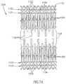
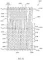
- FIGS. 3A-3Bare plan layouts of a slit-type flow reducing implant, in accordance with an exemplary embodiment of the invention.
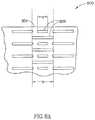
- FIG. 3Cis an isometric view of the flow reducing implant of FIG. 3A mounted on a balloon catheter delivery system, in accordance with an exemplary embodiment of the invention
- FIGS. 4A-4Bare plan layouts of a slit-type flow reducing implant, in accordance with an exemplary embodiment of the invention.
- FIGS. 4C-4Dare a plan layout and isometric view, respectively, of a slit-type flow reducing implant with a smooth rim, in accordance with an exemplary embodiment of the invention.
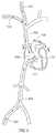
- FIG. 5is a vascular path to a coronary sinus, in accordance with an exemplary embodiment of the invention.
- FIGS. 6A-6Care three exemplary vise embodiments that reduce flow through a blood vessel, in accordance with an exemplary embodiment of the invention.
- FIGS. 6D-6Fshow three exemplary clamp embodiments that reduce blood flow through vessel 1002 , in accordance with exemplary embodiments of the invention.
- FIG. 6Gillustrates an exemplary endoscopic tool for releasing a blood vessel reducing clip, in accordance with an exemplary embodiment of the invention
- FIGS. 7A and 7Bare a plan view and an isometric view of a flow reducing implant embodiment with anchors, in accordance with an exemplary embodiment of the invention.
- FIG. 8Ais a portion of a plan layout of a section of a flow reducing implant with selective narrowing control, in accordance with an exemplary embodiment of the invention.
- FIG. 8Bis a side cross-sectional view of a flow reducing implant and a matching catheter for reducing a diameter of the flow reducing implant, in accordance with an exemplary embodiment of the invention.
- FIG. 8Cis a two-part flow reducing implant, in accordance with an exemplary embodiment of the invention.
- FIG. 8Dis a flow reducing implant and insert, in accordance with an exemplary embodiment of the invention.
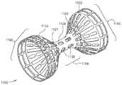
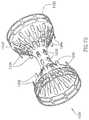
- FIG. 8Eis an isometric view of a dual layer flow reducing implant, in accordance with an exemplary embodiment of the invention.
- FIGS. 9A-9Gare embodiments of flow reducing implant, in accordance with exemplary embodiments of the invention.
- FIGS. 10A-10Bare an isometric view and detail, respectively, of a ringed mesh-type flow reducing implant embodiment, in accordance with an exemplary embodiment of the invention.
- FIG. 11is an isometric view of a partially covered mesh-type flow reducing implant embodiment, in accordance with an exemplary embodiment of the invention.
- FIG. 12is an isometric view of a sheath-type flow reducing implant, in accordance with an exemplary embodiment of the invention.
- FIG. 13is longitudinal section of an inflatable tube-type flow reducing implant, in accordance with an exemplary embodiment of the invention.
- FIG. 14is a longitudinal section of a flow reducing implant with shape-conforming elements, in accordance with an exemplary embodiment of the invention.
- FIG. 15is a plan layout of a cord-type flow reducing implant, in accordance with an exemplary embodiment of the invention.
- FIG. 1is a schematic showing of a flow reducing implant 100 installed in a coronary sinus vein 102 , in accordance with an exemplary embodiment of the invention.
- Coronary sinus 102drains a plurality of cardiac veins 106 into a right atrium 104 .
- the cardiac circulationis generally hierarchical and comprises of stages of reducing (or increasing) diameter.
- veins 106drain a plurality of thin venules 108 , which, after a few stages, drain a plurality of capillaries 110 .
- Capillary 110is fed by a plurality of arterioles 112 , which, after a few stages, are fed by a plurality of coronary arteries 114 and 120 .
- a stenosis 116is shown in a coronary artery 114 . While the cardiac circulation is generally hierarchical, some connection exists between different branches. Occasionally, the existence of stenosis 116 will cause a collateral connection 118 to spontaneously form (or widen an existing connection) between coronaries 114 and 120 , bypassing stenosis 116 .
- a flow reducing implant 100is placed in coronary sinus 102 and has a narrowing significant enough to encourage the formation of collateral connection 118 .
- collateral connection 118is caused by an increase in venous blood pressure, which, in turn, increases the pressure in the capillaries and/or causes retro-flow in the capillaries and/or causes drainage of the capillaries directly into the heart.
- constriction of coronary sinus 102will generally cause the formation of collateral circulation and/or otherwise improve the condition of patients with blocked coronary arteries.
- Alternative or additional hypothesesthat are optionally used to select the constrictive effect of flow reducing implant 100 include:
- Flow reducing implant 100increases the pressure in the coronary capillaries, thus increasing perfusion duration.
- FIG. 2is a schematic side view of flow reducing implant 100 , in accordance with an exemplary embodiment of the invention.
- Flow reducing implant 100comprises a narrowed section 204 and at least one flared section 200 (and 202 ) leading into narrowed section 204 .
- Section 200 (and 202 )includes sections 210 and 206 that are inclined relative to the wall of coronary sinus 102 and sections 212 and 208 that are parallel to the wall.
- flow reducing implant 100is expandable and shortens somewhat during expansion: having a length of 20 mm before expansion and about 18.8 mm after expansion.
- a non-shortening designis used, for example a mesh as in peristaltic stents, such as described in U.S. Pat. No. 5,662,713, the disclosure of which is incorporated herein by reference.
- An exemplary material thicknessis 0.15 mm, however, thinner or thicker materials may be used.
- Other exemplary lengthsare 5 mm, 12 mm, 24 mm, 35 mm 45 mm and any smaller, intermediate or larger size.
- the lengthis optionally selected to match a physiological size of the target vein (e.g., length and curves) and/or to ensure good contact with vein walls.
- the length of narrowed section 204may be, for example, 0.5 mm, 1 mm, 2 min, 3 mm, 5 mm or any smaller, intermediate or larger length, for example selected to achieve desired flow dynamics
- An exemplary inner diameter of the flared sectionsis between 2 mm and 30 mm, for example, 5 mm, 10 mm, 15 mm, 20 mm or any larger, smaller or intermediate diameter, for example selected to match the vein diameter.
- the ratio between the cross-section of narrowed section 204 and the flares of flow reducing implant 100is 0.9, 0.8, 0.6, 0.4, 0.2 or any larger, smaller or intermediate ratio, for example selected to achieve desired flow dynamics and/or a pressure differential across the flow reducing implant.
- FIG. 1While a circular cross-section is shown, other cross-sections may be used, for example, polygona and ellipsoid.
- a potential advantage of non-circular cross-sectionsis that the implant is less likely to migrate axially and/or rotate.
- the outside of the flow reducing implantis roughened and/or otherwise adapted to adhere to the vein wall.
- the cross-section shape and/or orientationoptionally changes along the length of flow reducing implant 100 .
- FIG. 3Ais a plan layout of a slit-type flow reducing implant and FIG. 3B is a detail of FIG. 3A , in accordance with an exemplary embodiment of the invention.
- this plan layoutthe ends of sections 200 and 202 are caused to be parallel to the vessel wall when flow reducing implant 100 is expanded.
- the outside flare of flow reducing implant 100is defined by sections 340 , 342 and 344 , shown in FIG. 3B .
- the total length of these sectionsdefines the maximum flare length.
- the bending areas in and between these sectionsdefine the relative force required to expand the flare region relative to the area near the rim. If the rim region is more difficult to expand and/or is expanded less than the adjacent regions, the expansion of flow reducing implant 100 will tend to cause the rim to be bent in, or at least not flare out.
- the existence of sections 340 , 342 and 344can be used to determine the final shape of the flare.
- additional sections 346are provided around the circumference of flow reducing implant 100 , which define outer slits in flow reducing implant 100 , which outer slits may have a maximum expansion that is the same or smaller than that nearby (axially inwards) slits. This design can also be used to control the shape of the flare.
- a flow reducing implantis characterized by this maximum diameter, which may be used, for example, for selecting a particular flow reducing implant to match a patient.
- the balloonis aligned with flow reducing implant 100 so that it only contacts the flare region or only contacts the non-flare regions of flow reducing implant 100 .
- FIG. 3Cis an isometric view of flow reducing implant 100 ( FIG. 3A ), mounted on a balloon catheter delivery system 302 , in accordance with an exemplary embodiment of the invention.
- flow reducing implant 100is formed by cutting out of a sheet of metal or a tube, for example, using laser, water cutting, chemical erosion or metal stamping (e.g., with the result being welded to form a tube).
- flow reducing implant 100is woven (e.g. of metal or plastic fiber), for example, using methods as well known in the art.
- narrowed section 204is made using a different method from flared sections 200 and 202 , for example, the flared sections being woven and the narrowed section being cut from sheet metal.
- flow reducing implant 100includes with a constraining ring that prevents the expansion of narrowed section 204 .
- a standard balloon catheter with a single expansion areafor example the Fox CatheterTM by Jomed, Inc.
- the narrowed sectionis prevented from expanding while flared sections 200 and 202 expand under pressure.
- Various methods for preventing the narrow section from expandingare described below, for example, providing different mechanical properties, different designs or additional elements at the narrowed sections relative to the non-narrowed sections.
- flow reducing implant 100is cut out of a sheet and then spirally twisted around a mandrel to form the shape of flow reducing implant 100 .
- flow reducing implant 100is cut out of a tube, with the flared parts being spiral cuts and the narrowing part being a ring cut.
- flow reducing implant 100is formed as a coil spring, with axially varying relaxation positions.
- flow reducing implant 100is adapted for use in a coronary sinus or other coronary vein or other veins having non-muscular walls. Veins are typified by having a low degree of elasticity and being relatively sensitive to tears (as compared to arteries).
- the edges of flow reducing implant 100are curved inwards or curled, for example as shown by reference 130 in FIG. 1 , Alternatively or additionally, the edges are folded back and/or smoothed to remove sharp edges.
- the parallel sections 208 and 212( FIG. 2 ) are made long enough to support flow reducing implant 100 without harming coronary sinus 102 .
- flow reducing implant 100 or at least a larger diameter portion thereofis made soft enough and/or with a low spring constant, to prevent flow reducing implant 100 from applying too much pressure on the coronary flow reducing implant wall.
- the flares of flow reducing implant 100are coated with a biologically inert flexible coating, for example, a soft silicone elastomer or another soft plastic or rubber material such as Latex, Teflon and/or Polyurethane (for example Angioflex, a biologically inert polyurethane plastic).
- FIGS. 4A-4Bare plan layouts of slit-type flow reducing implant 100 , in accordance with an exemplary embodiment of the invention.
- rim 402is defined by sections 440 and 446 . As shown, these sections are designed to provide a relative smooth rim, possibly with small amounts of distortion (so rim 402 remains smooth) where the sections connect to sections 442 and 444 . Together, sections 442 , 444 and 446 define outer slits for rim 402 .
- Patients that are candidates for an angiogenesis-promoting proceduremay have significant vascular compromise of the coronary circulation with constriction and/or lack of flow in one or more coronary arteries that supply blood to the coronary tissue.
- An invasive surgical procedureeven to percutaneously introduce and/or position a reducing implant 100 into the coronary sinus, may trigger a cardiovascular accident with untoward sequella.
- averting and/or limiting the amount of time that the vasculature is invaded, for example, during use of a balloon catheteris desirable in some individuals.
- FIGS. 4C-4Dare a plan layout and isometric view, respectively of a slit-type flow reducing implant 1100 with a smooth rim, in accordance with an exemplary embodiment of the invention.
- slit-type flow-reducing implant 1100comprises shape memory materials that automatically achieve a final configuration state upon exiting, for example, a delivery catheter or sheath, thereby averting the use of a balloon catheter for initial installation of slit-type flow-reducing implant 1100 .
- a balloon expended materialfor example one that plastically deforms by expansion, may be used.
- slit-type coronary flow-reducing implant 1100shown in a plan view in FIG. 4C , contains preformed slits 1102 , in accordance with an exemplary embodiment of the invention.
- Slits 1102(and optionally a set of slits 1104 in a second or further row) define a row 1122 (and a row 1124 ) along an outer edge 1132 of slit-type flow-reducing implant 1100 that, in the unexpanded state comprise at least one edge 1132 that has a wavy configuration.
- edge 1132becomes smooth while slits 1102 assume a rectangular appearance, with edge 1132 transverse to a slit 1126 , for example.
- the slits of the rimare wider than the slits of the rest of implant 1100 , thereby affecting its final expanded configuration.
- slit-type coronary flow-reducing implant 1100is transferred to its deployment site in coronary sinus using a guide sheath without accompaniment by a balloon catheter. As slit-type coronary flow-reducing implant 1100 reaches its destination and exits its guide sheath, coronary flow-reducing implant 1100 automatically expands into its final shape, shown in FIG. 4D . In this manner, slit-type coronary flow-reducing implant 1100 does not require manipulation and/or expansion using, for example, a balloon catheter.
- a balloon cathetermay be used to facilitate expansion of slit-type flow-reducing implant 1100 , for example, when it is made of materials that do not automatically attain a memorized shape.
- rows of slits 1122 and/or 1124have lengths and/or orientations that promote flow-reducing implant 1100 to form into a final shape under pressure of a balloon catheter, therefore, installing with a minimal amount of time and/or stress to the surrounding tissue.
- slit-type coronary flow-reducing implant 1100is designed to alter its shape in response to manipulation and/or expansion following installation.
- slits 1138expand so that a narrow passage 1168 automatically attains a first diameter during installation.
- a balloon catheteris introduced into narrow passage 1168 and inflated to press radially outward on narrow passage 1168 .
- a pressurefor example, of between 7 and 8 atmospheres or less than 7 or greater than 8 atmospheres, depending, for example on the stiffness of the component materials, causes expansion slits 1138 to expand to a larger cross section. This causes narrow section 1168 to have a larger diameter than it had immediately following installation.
- slits 1138may be oblique, thus possibly requiring a different degree of force to expand and/or providing a twisting of the deployed implant.
- Providing opposing oblique slitsmay be used to providing a shortening of the implant.
- flow-reducing implant 1100when flow-reducing implant 1100 is installed, little or no blood migrates through the walls of narrow passage 1168 and/or a flare 1160 to contact the walls of the coronary sinus. This, for example, is achieved by a narrow configuration of the slits. Alternatively or additionally, the length of the slits decreases near narrowing 1168 .
- the slitse.g., not only slits 1102 and 1104 at the rim
- the slitsare increased in number, while their width is reduced.
- the viscosity of the bloodimpedes its flow through the decreased width of the slits while the increased number of slits may fosters expansion of implant 1100 . This may result in a net reduction in blood flow through the implant walls.
- the slit widthmay be used to help define the device geometry. For example, slits (actually spaces) 1104 are wider than the other slits. If, for example, slits 1104 are made wider than slits 1102 , a curved in rim may result.
- slitsare arranged in alternating rows of long and short slits.
- the size and/or density of slitsis larger near the rims than near the center of implant 1100 .
- the length of the slitsincreases as a function of the distance from narrowing 1168 .
- the material of implant 1168is distorted by the expansion.
- the slitsare distorted and the material is distorted to conform to these distortions.
- the short axial slit nearest the rimachieves a trapezoid rather than rectangular shape.
- the expanded configurationsare idealized, with an actual expanded shape possibly including step-like distortions caused by the discrete pattern of the slits in the implant.
- FIG. 5shows a vascular path to coronary sinus 102 , in accordance with an exemplary embodiment of the invention.
- flow reducing implant 100is implanted using a trans-vascular approach, for example, from the venous system or by crossing through an intra-chamber wall in the heart.
- the delivery systemis inserted through a jugular vein 510 or a subclavian vein 512 to a right atrium 506 of a heart 500 via a superior vena cava 508 and/or a femoral vein 502 , via an inferior vena cava 504 .
- the delivery systemis guided (e.g., through a sharp bend) to an opening 514 into coronary sinus 102 .
- a valveexists at the entrance to coronary sinus 102 .
- FIGS. 6A-6Care three exemplary vise embodiments, 1000 , 1010 and 1020 , that reduce flow through a blood vessel 1002 , and are applied from outside the blood vessel, in accordance with exemplary embodiments of the invention.
- Vise 1000( FIG. 6A ) is a band having any ratchet mechanism for preventing opening as known in the art; vise 1010 is a clip-like clasp; and vise 1020 is an elastic spiral.
- the band, clip and/or spiralare distortable.
- a balloon cathetercan be inserted into the vessel and expanded, causing the spiral, clip and/or band to distort.
- the bandcomprises a plurality of slits (e.g., as in FIG. 8A ), that accommodate such distortion.
- FIGS. 6D-6Fshow three exemplary clamp embodiments, 1030 , 1040 and 1050 , that reduce blood flow through vessel 1002 , in accordance with exemplary embodiments of the invention.
- Clamp 1030is a clip that shuts down part of the cross-section of vessel 1002 ;
- clamp 1040is also a clip, that only distorts the cross-section of vessel 1002 ;
- clamp 1050is a tack (or suture) that transfixes a part of vessel 1002 .
- Non-piercing clipsare optionally designed to have rounded tip and/or non-meeting tips to reduce danger of piercing.
- FIG. 6Gillustrates an exemplary endoscopic tool 1060 for releasing blood vessel reducing clip 1010 , in accordance with an exemplary embodiment of the invention.
- Clip 1010is held between a flat plate 1060 and a Trans-axially movable arm 1062 with a broadened tip. Retracting arm 1062 towards tool 1060 causes the clip to open and moving arm 1062 in a Trans-axial direction frees the clip.
- Various other clip deployment mechanismsfor plastic and elastic materials
- the procedureis performed through a key hole and using a working channel or a different keyhole to provide visual verification of the procedure. Alternatively or additionally, radiological verification may be provided.
- Various implantsare known in the art for applying bands to blood vessel and may be used for the example of FIG. 6A as well.
- Flow-reducing implants 1000 , 1010 , 1020 , 1030 , 1040 and/or 1050may be deployed on vessel 1002 .
- these implantsmay be deployed onto tissue enclosing vessel 1002 .
- the implantmay be deployed onto (and/or piercing through) a pericardium and/or cardiac muscle tissue.
- FIGS. 7A and 7Bare a plan view and an isometric view of a flow reducing implant 1200 with anchors, in accordance with an exemplary embodiment of the invention.
- an anchor-type flow-reducing implant 1200comprises at least one anchor 1202 that prevents motion of anchor-type flow-reducing implant 1200 in relation to a blood vessel.
- at least one anchor 1202 and/or 1204are parallel to the blood vessel and catch on the tissue of the blood vessel to prevent displacement of anchor-type implant 1200 .
- the anchorsare shown as flat, blunt and axial tabs, other designs may be used, for example, sharp, curled and/or oblique to the vessel axis.
- implant 1200comprises one of row of anchors 1202 and/or row of anchors 1204 that prevent motion.
- anchors 1202 and/or 1204are substantially parallel to the longitudinal axis of implant 1200 when it is in the non-expanded state and in the expanded state, shown in FIG. 7B .
- this parallel layoutis achieved by the anchors being attached only to the rims and not the flaring section of the implant. thus, they tend to stay in the plane of the rim, which may be, for example parallel to the blood vessel wall or even pointing the anchors towards the wall (e.g., if the rim is curled in)
- anchor 1202 and/or 1204are connected to anchor-type flow-reducing implant 1200 and protrude from its surface to into the surrounding tissue with a pressure sufficient to prevent motion of the implant without causing tissue irritation. This can be important in veins, for example, that have less thickness than comparable arteries.
- anchorsthat press with greater force or are pre-stressed to a greater non-parallel angle into the surrounding tissue may be desirable.
- anchor 1202 and/or 1204are designed for such a vessel and press radially outward from the wall of anchor-type flow-reducing implant 1200 , against the surrounding tissue.
- anchor-type flow-reducing implant 1200includes anchors 1202 that have a free end that is not attached to narrow passage 1168 and, for example, blunt to avert tissue irritation.
- one or more deployed anchors 1202are parallel to a longitudinal axis 1210 of anchor-type flow-reducing implant 1200 , and point towards one or more anchors 1204 .
- the vesselsmay form a lumen with an ellipsoid cross section.
- An anchor-type flow-reducing implant with anchors 1202 and/or 1204 that point toward one anothermay tend to migrate laterally and/or displace to one side of the other of the lumen.
- anchors 1202 and/or 1204 of anchor-type flow-reducing implant 1200may be configured to compensate for not-cylindrical implantation environments.
- anchors 1202 and/or 1204may be configured to point in a substantially perpendicular direction to longitudinal axis 1210 of anchor-type flow-reducing implant 1200 , thus tending to prevent lateral movement of implant 1200 .
- anchors 1202 and/or 1204may be connected to an edge 1232 and pointing away from anchors 1204 that are connected to an edge 1234 . In this way, anchors 1202 and/or 1204 press into tissue at the edge of the implant that is stronger and/or exhibits a more uniform circumference.
- anchors 1202 and/or 1204can be oriented in an oblique direction oblique to a transverse axis 1220 and/or longitudinal axis 1210 , for example, to prevent migration in an environment where there is strong flow force of the blood stream that tends to exert force and displace implant 1200 .
- anchorsare shown cut out of the long slits, alternatively or additionally, the anchors may be cut out of short slits, for example a slit 1125 .
- FIG. 8Ais a portion of a plan layout of a section of a flow reducing implant 800 with selective narrowing control, in accordance with an exemplary embodiment of the invention.
- Flow-reducing implant 800includes a narrowed section 804 .
- section 804is also expandable, for example, having a plurality of thin slits 806 defined therein. This allows the minimum diameter of flow-reducing implant 800 to be increased after deployment.
- section 804is stiffer than the rest of flow-reducing implant 800 , so that pressure suitable for expanding flow-reducing implant 800 will not expand section 804 .
- flow-reducing implant 800is a self-deploying implant and section 804 is plastically deformed using a balloon.
- a delivery system used for flow-reducing implant 800may include both a restraining element and a balloon element. In case the implantation of a flow-reducing implant fails, extreme expansion of section 804 will substantially negate the function of flow-reducing implant 800 and may allow a new flow-reducing implant to be implanted within or through flow-reducing implant 800 , at a later time.
- two sizes of slits 806are provided, with the degree of resistance to defamation being determined by the sizes and/or relative sizes of the slits.
- FIG. 8Bis a side cross-sectional view of a flow reducing implant 820 and a matching reducing catheter 840 , which can be used to reduce the narrowing of implant 820 , in accordance with an exemplary embodiment of the invention.
- Flow-reducing implant 820can be formed generally like flow-reducing implant 800 , in that its narrowed section has a selectable diameter.
- Flow-reducing implant 820includes a plurality of engagement points 822 that are adapted to be engaged by a plurality of engagers 846 of a catheter 840 .
- engagement points 822include a protruding arc 824 that is engaged by a barbed tip at engager 846 .
- catheter 840includes a body having a diameter similar to (or smaller, e.g., to allow for spring-back) the desired final diameter of flow-reducing implant 840 .
- engagers 846When engagers 846 are inserted adjacent to engagement points 822 and catheter 840 is rotated, the barbs engage the arcs.
- One or more wires 844are retracted, retracting engagers 846 and arcs 824 towards catheter body 842 .
- body 842distorts barbs 846 so that they release arcs 824 so that catheter 840 can be removed.
- engagement/release mechanismscan be used, for example, barbs that match apertures in flow-reducing implant 820 or provision of grasping heads (e.g., pliers) at engagers 846 .
- the narrowing procedureis performed under medical imaging, for example, fluoroscopy.
- engagement meanssuch as barbs 846 are used to remove the entire flow-reducing implant, optionally for replacement with a different flow-reducing implant and/or re-deployment of the same flow-reducing implant using a balloon on catheter 840 or after removal from the body.
- Flow-reducing implant 820is a shape memory flow-reducing implant that expands when subjected to body temperature. A balloon having cool fluid circulating there through is brought into flow-reducing implant 820 to cause flow-reducing implant 820 to shrink back to an unexpanded configuration and/or be more amenable for removal.
- the decision to remove and/or change a diametermay be made only after a time period, during which vascular tissue may have grown into and attached onto flow-reducing implant 820 .
- FIG. 8Cis a two-part flow reducing implant 850 including a tubular section 852 and a reducing section 854 , in accordance with an exemplary embodiment of the invention, Reducing section 854 may be manufactured to match tubular section 852 or it may be a flow-reducing implant design as described herein or a flare, for example. In either case, tubular section 852 is optionally used to isolate reducing section 854 from the enclosing vascular tissue, thus allowing easier manipulation and/or replacement of section 854 . Alternatively or additionally, for example in the coronary sinus, the use of tubular section 852 may be desirable for prevention of damage to the vascular tissue.
- tubular section 852is provided for other reasons, for example, to provide support for axial fixation of reducing section 854 and/or to reduce damage to a surrounding blood vessel.
- tubular section 852 and reducing section 854may be of similar sizes or tubular section 852 may be considerably longer, for example, 25%, 50%, 100%, 200%, 400% or any smaller, intermediate or greater size ratio.
- the two sectionsmay be inserted at the same time or at different procedures. The two sections may be inserted using a same delivery system or, for example, using two separate delivery systems.
- Tubular section 852may be of various designs, for example, be a coil or mesh stent, a stent graft, a graft with stents (or other attachment means) at its ends and/or a plain graft.
- Tubular section 852 and/or the tips of a flow-reducing implantmay be made flexible and/or elastic to adapt to changes in blood vessel diameter.
- FIG. 8Dis a flow reducing implant 860 including a narrowing insert to reduce the diameter of implant 860 , in accordance with an exemplary embodiment of the invention.
- Insert 870has its expansion inside flow-reducing implant 860 limited by a narrowed diameter section 862 of flow-reducing implant 860 .
- insert 870has a funnel shape, with a narrow diameter opening 874 and a larger diameter opening 876 .
- Insert 870may be formed, for example, from a mesh and may be plastically, elastically, super-elastically and/or shape-memory deformed.
- the final geometry of insert 870is defined by its resting points against flow-reducing implant 860 .
- This resting pointscomprise, for example, a point 864 generally between the narrow and flared sections of flow-reducing implant 860 and a resting point 866 on the flared section of flow-reducing implant 860 .
- a ratchet mechanismis provided to anchor insert 870 in place.
- opening 874is narrowed further (if required), by advancing opening 876 towards narrowed section 862 of flow-reducing implant 860 .
- overcoming the ratchet mechanism and retracting opening 876 from section 862enlarges opening 874 .
- the ratchet mechanismcomprises a plurality of inclined barbs or anchors 868 , on flow-reducing implant 860 .
- the ratchet mechanism and/or locking mechanismcomprises a barb 872 on insert 870 .
- These ratchetsmay be overcome, for example, by reducing the size of opening 876 and/or by applying considerable force against the ratchet direction.
- a band or clipis applied to the outside of the enclosing blood vessel, urging flow-reducing implant 820 (e.g., at its narrow and/or broad sections) to close.
- the bandis applied alone, without a flow-reducing implant.
- Exemplary bands and other implantsare described in FIG. 6A-6G .
- Such implantsmay be used to plastically urge flow-reducing implant 820 closed, in which case, a pliers (optionally adapted to pass through a keyhole) may be used instead of a permanent clamp.
- the jaws of the pliersare optionally formed to have a cross-section matching desired cross-section of flow-reducing implant 820 .
- flow-reducing implant 820is elastic or super-elastic, and a permanent implant is implanted outside the blood vessel.
- the band or pliersis applied over a wide area, for example, 30%, 50%, 80% or any greater intermediate or smaller percentage of the length of flow-reducing implant 820 , to reduce damage to the blood vessel.
- the narrowing effectis applied to a weakened part of flow-reducing implant 820 , for example, a broad section thereof.
- flow of blood through slits 1125may add to turbulence of blood flowing through flow-reducing implant 1100 .
- Such turbulencemay contribute to the formation of blood clots that cause embolitic sequella, for example a stroke, at distant locations in the body.
- flow-reducing implants with non slit wallsmay not exhibit appropriate expansion capabilities and/or facilitate in situ revision of its configuration.
- FIG. 8Eis an isometric view of a dual layer flow-reducing implant 1400 in accordance with an exemplary embodiment of the invention.
- dual layer flow-reducing implant 1400comprises a first flared section 1450 and/or a second flared section 1460 .
- first flared section 1450and/or a second flared section 1460 .
- second flared section 1460For purposes of clarity, the components of flare 1460 , alone, will be focused on, though similar features can be applied to flared section 1450 .
- dual layer flow-reducing implant 1400comprises a flared section 1460 comprising an external cone 1420 and an internal cone 1410 .
- Internal cone 1420for example, comprises slits 1422 and 1426 and external cone 1410 comprises slits 1412 and 1416 so that cones 1410 and 1420 can be transported to an implantation site in a non-expanded state and expanded at the implantation site.
- cone 1410 and/or 1420may be desirable and can be incorporated into their respective designs so that cone 1410 and/or 1420 expand to a first diameter when pressed radially outward by a balloon catheter at a first expansion pressure. Cone 1410 and/or 1420 can then expand to a second, greater, diameter when pressed radially outward by a balloon catheter at a second, greater, expansion pressure.
- flow-reducing implant 1400may be implanted into a vessel with a relatively slow flow speed and/or low pressure.
- implantation in the coronary sinus narrow area 1440may fill with tissue that aids in anchoring implant 1400 without risk of an embolism.
- a clotforms in area 1440 and stabilizes in its position. Stabilized clot in area 1440 becomes incorporated into the surrounding tissue and against dual cone flow-reducing implant 1400 so that it is further stabilized in its position.
- slits 1422 and 1426can be rotated, prior to implantation, in relation to slits 1412 and 1416 so that blood flow in direction 1451 is substantially stopped to various degrees.
- reducing implant 1400may be implanted into a vessel with a relatively higher flow speed and/or higher pressure, for example a main trunk of an artery thereby protecting the patient against the dangers of embolism migration.
- the alignment of slits 1422 and 1426is optionally set prior to implantation in a blood vessel in relation to slits 1412 and 1416 , in order to establish a pre-defined blood flow pattern, and the two layers expanded or allowed to expand, together.
- cones 1410 and 1420have, for example, a friction surface interface and/or interdigitation.
- the two layersmay be deployed in different ways, for example, the inner layer may be plastically deployed and the outer layer self-deployed. Possibly, the profile of the two layers does not match along its entire length.
- the outer layeris plastically deformed by a self-deploying inner layer (which self deployment may also provide the friction for locking).
- cone 1420may be rotated, for example using a suitable internal engaging catheter, after implantation
- the flared sections 1450 and 1460need not be symmetric.
- the implantmay also selecting between flow blockage at one section, the other and optionally both. Flow only into space 132 , may assist in clot formation. Flow only out of space 132 may assist in collapsing a surrounding blood vessel,
- FIGS. 9A-9Gillustrate various flow-reducing implant variations, in accordance with exemplary embodiments of the invention. While a sigmoid-like flare is shown, a linear or other flared design may also be provided.
- FIG. 9Ais a flow-reducing implant 900 with having a narrowed section 902 and a single flared section 904 . Narrowed section 902 may point upstream or down stream.
- One potential advantage of this designis that the delivery system is less likely to get caught inside narrowed section 902 .
- Another potential advantageis that a completely obstructing implant can be provided. In an exemplary embodiment of the invention, however, even such a completely obstructing implant has smooth sides, to prevent damage to the coronary sinus. Possibly, the outer diameter of the completely obstructing implant or a nearly complete flow-reducing implant is increased beyond that of the coronary sinus, to prevent dislodgment of the implant. Alternatively or additionally, one or more barbs on the outside of the implant may be provided.
- a cone shaped flow-reducing implantis provided with one or more openings for blood flow on the face of the cone, rather than at its apex as shown.
- the narrowingmay be a valve, for example, a valve that opens, to a full or partial diameter, after a suitable pressure is achieved in the coronary sinus distal from the right atrium.
- a leaflet valve or other type of vascular valve as known in the heartmay be provided.
- FIG. 9Bshows an alternative flow-reducing implant 910 ; with two narrowed sections 912 and 916 sandwiching a flared section 914 between them, in accordance with an exemplary embodiment of the invention.
- the different narrowed sectionshave a different inner diameter.
- the narrowed sectionsare selectively expanded using a balloon to achieve a desired pressure profile.
- FIG. 9Cis an alternative flow-reducing implant 920 with three narrowed sections 922 , 926 and 929 and two flared sections 924 and 928 between the narrowed sections, in accordance with an exemplary embodiment of the invention.
- Certain blood vesselsmay exhibit a taper along their length, for example forming an angle 1310 , shown in FIG. 9D . Vessels that change in size along their length may occur, for example, in the coronary sinus as it joins into the right atrium.
- a tapered blood vesselit may be desirable to utilize a tapered-type flow-reducing implant 930 ( FIG. 9E ), seen in detail in FIG. 9D , in accordance with exemplary embodiments of the invention.
- FIG. 9Dis an isometric view of an exemplary embodiment of a tapered flow-reducing implant 1300 , (with a similar configuration to implant 930 ) in accordance with an exemplary embodiment of the invention.
- Tapered flow-reducing implantcomprises a smaller flared section 1330 , a narrowed section 1340 and larger flared section 1320 .
- the size of smaller flared section 1330is governed one or more slits 1342 that are transverse to the axis of narrowed section 1340 and one or more slits 1346 that are longitudinal to the axis of narrowed section 1340 .
- the size of larger section 1320is governed, for example, by two or more slits 1322 that are transverse to the axis of narrowed section 1340 and/or two or more slits 1320 that are longitudinal to the axis of narrowed section 1340 .
- slits 1342 , 1346 , 1322 and/or 1326be varied size and/or configuration to govern the shape of flared sections 1320 and/or 1330 .
- slits 1342 , 1346 , 1322 and/or 1326may be have various arrangements to provide different contours to flared sections 1320 and/or 1330 and/or narrowed section 1340 .
- openings 1330 and 1320are shown as being round, they may have a variety of configurations to conform to different vessel configurations as noted above. Further, the ratio between opening 1330 and 1320 may be varied to conform to any vessel diameter where flow-reducing implant 1300 is implanted. As in other figures, the material of the implant is shown distorted, while in some embodiments, it may be the slits, possibly in addition to the material, which is distorted.
- FIG. 9Eis a tapered flow-reducing implant 930 in which one flared section 932 has a smaller diameter than a second flared section 936 , but larger than an intermediate narrowed section 934 , in accordance with an exemplary embodiment of the invention.
- FIG. 9Fis a flow-reducing implant 940 that is not axially and/or rotationally symmetric around its axis, in accordance with an exemplary embodiment of the invention.
- a first flared section 946is distorted relative to an axis defined by a second flared section 942 and a narrowed section 944 .
- flow-reducing implant 940is curved.
- asymmetric or curved flow-reducing implantsinclude special markings, for example, radio-opaque or radio-transparent areas, to assist correct orientation of flow-reducing implant 940 in a blood vessel.
- FIG. 9Gis a flow-reducing implant 950 , in which a narrowed section 954 is a sleeve 954 , in accordance with an exemplary embodiment of the invention.
- Sleeve 954for example, is formed of a flexible graft material, such as Dacron or GoreTex.
- Flow-reducing implant 950further comprises at least one of two outer rings 952 and 956 that serve to anchor flow-reducing implant 950 in the blood vessel.
- a potential advantage of using a sleeveis that it can bend to conform to the vein geometry and/or dynamics. Other flow-reducing implant designs can also bend.
- the graft materialis elastic, so it can serve as a pressure limiting valve, to better control coronary sinus pressure.
- a constraining ringis provided on the outside of section 954 , to restrict the lumen of flow-reducing implant 950 .
- the ringis placed on flow-reducing implant 950 during the procedure, to achieve a desired narrowing effect.
- the ringis expandable, for example using a balloon, to allow controlling the narrowed section of flow-reducing implant 950 .
- the ringis sutured to narrowed section 954 .
- section 954is stiffened, for example, using a wire, as known in the art of stent-grafts.
- flow-reducing implant 100is provided in kit form, possibly with a delivery system, a flow-reducing implant diameter control system, additional flow-reducing implants, external bands and/or other means for reducing its inner diameter, and including instructions for use and/or size markings.
- flow-reducing implant 940is provided inserted into a delivery system or packaged with a delivery system.
- a flow reducing implantis constrained by providing a band on the outside of the implant.
- FIGS. 10A-10Bare an isometric view and detail, respectively, of a ringed mesh-type flow reducing implant embodiment, in accordance with an exemplary embodiment of the invention.
- mesh-type flow-reducing implant 1500( FIG. 10A ) comprises a flare shoulder 1502 and/or a flare shoulder 1504 that are relatively long in length, for example, to increase the area of contact between flow-reducing implant 1500 and surrounding vessel walls.
- tissuemay grow through the mesh of flare shoulders 1502 and/or 1504 , providing good anchorage of mesh-type flow-reducing implant 1500 .
- mesh-type flow-reducing implant 1500comprises and/or is coated with materials that promote tissue ingrowth.
- a rim 1620which may be, for example jagged or smooth is also optionally provided on each shoulder.
- the initial shape of mesh-type flow-reducing implant 1500is governed by one or more bands 1522 and/or 1524 that constrict an area 1528 of mesh-type flow-reducing implant 1500 .
- the surrounding tissuecollapses onto mesh-type flow-reducing implant 1500 to reduce blood flow through the walls of constriction area 1528 . While two bands 1522 and 1524 are shown, a single band, for example band 1522 alone, may be used to create constriction area 1528 .
- an operator manually tying their ends together, prior to implantationadjusts the rings formed by band 1522 and/or 1524 in circumference, for example. Adjustment of band 1522 and/or 1524 prior to implantation allows the operator to establish constriction area 1528 with a specific size to reduce blood flow and thereby promote angiogenesis.
- a balloon catheterfor example, is expanded in area 1562 to cause expansion of bands 1522 and/or 1524 , thereby expanding area 1562 to increase blood flow there through. In this fashion, blood reduction through flow-reducing implant 1500 can be regulated prior to placement and/or following placement of flow-reducing implant 1500 in a blood vessel.
- band 1524has a smaller diameter than band 1522 , providing two levels of expansion. For example, so that as a balloon catheter is expanded to a first diameter, it expands smaller diameter band 1524 , increasing the diameter of constriction area 1528 to a first expanded diameter. Should further increase in flow be desired, a balloon catheter is expanded to a second diameter and expands larger diameter band 1524 and/or smaller diameter band 1524 , increasing the diameter of constriction area 1528 to a second expanded diameter.
- Ring 1524has, for example, a diameter of 6 millimeters while ring 1522 has a diameter of 8 millimeters so that area 1562 has flow passage of 6 millimeters.
- area 1562has flow passage of 6 millimeters.
- FIG. 10Bis a detail of an embodiment of ring 1522 comprising an adjustable band 1540 that forms ring 1522 and is held at a specific diameter by a clasp 1544 .
- adjustable band 1540is maintained at a specific diameter by a clasp 1546 .
- clasps 1544 and/or 1546hold adjustable band 1540 so that during implantation, ring 1522 remains at a specific diameter until, for example, an expanding balloon catheter is expanded against adjustable band 1540 and the diameter of ring 1522 is expanded.
- clips 1544 and 1546comprise, for example, a nylon material that holds band 1522 at a specific diameter and allow expansion of the diameter only under expansion pressure from, for example, a balloon catheter.
- flare shoulders 1504 and/or 1502are 0.5 centimeters to 1 centimeter in length through they could be less than 0.5 centimeters or greater than 1 centimeter in length, for example, depending upon vessel configuration.
- FIG. 11is an isometric view of a partially covered mesh-type flow reducing implant embodiment 1600 , in accordance with an exemplary embodiment of the invention.
- Mesh-type flow reducing implant 1600comprises a covering 1614 over or inside narrow section 1624 , implanted in a blood vessel 1680 , shown in cross section.
- mesh-type flow reducing implant 1600comprises one or more flare shoulders 1602 that contact blood vessel 1680 to provide anchoring.
- a rim 1620which may be, for example jagged or smooth is also optionally provided on each shoulder.
- mesh-type flow reducing implant 1600comprises a covering 1614 the restricts blood flow through the surface of flow reducing implant 1600 and/or blood turbulence in an area of constriction 1624 , thereby reducing danger of embolitic migration problems.
- covering 1614comprises a separate, flexible layer, that is attached to flow reducing implant 1600 at several points (e.g., at constriction area 1624 and/or flare shoulders 1602 ) to prevent tearing when implant 1600 expands. Prior to expansion, for example, covering 1614 is folded and/or pleated. Alternatively or additionally, covering 1614 has a low bulk and, for example, is integrated into flow reducing implant 1600 structure, for example, so that it substantially spans the open areas of the mesh. Examples of materials comprising covering 1614 , include gortex, latex and/or silicone, on the inside and/or outside of flow reducing implant 1600 .
- Sheath projection 2352can be configured with grooves and/or projections to further control the amount of obstruction of the central blood flow stream.
- sheath 2352includes a stiffener ring which maintains its opening patent.
- one or more stiffening axial or radial strutsare provided to assist in maintaining the shape of sheath 2352 .
- FIG. 13is longitudinal section of an inflatable tube-type flow reducing implant 2400 , in accordance with an exemplary embodiment of the invention.
- Inflatable tube-type flow reducing implant 2400comprises a long wall 2406 , a portion of which is surrounded by a ring-shaped tube 2420 .
- tube 2420can be located along any portion of long wall 2406 and/or of any configuration that reduces blood flow through lumen 2114 .
- tube 2420replaces the function of ring 1522 of FIG. 10A .
- tube 2420has an interior space 2430 enclosed within a circular wall 2402 that is, for example, inflatable using a hose 2428 .
- tube 2420inflates so that interior 2430 has two or more cross sectional diameters, thereby allowing adjustment of narrow lumen 2114 to modify the amount of reduction in blood flow.
- Hose 2428is optionally removed or torn off after deployment. Alternatively or additionally, hose 2428 may be attached after deployment, for example having a needle tip used to inject fluid into tube 2420 . Alternatively or additionally, tube 2420 may be torn or punctured after implantation, to increase the diameter of the narrowing.
- tube interior 2430contains a material that absorbs liquid, thereby expanding. Following implantation, for example, tube 2420 absorbs liquid and interior 2430 increases in size until tube 2420 reaches its expanded state.
- wall 2402 and/or tube 2430comprise a resilient material, for example Nitinol, and expand to a final state without inflation.
- flow-reducing implant 2400and/or embodiments mentioned below, are manufactured from a biocompatible material, comprising, for example, a soft silicone elastomer and/or another soft material such as latex, Teflon, gortex, Kevlar and/or polyurethane.
- FIG. 14is a longitudinal section of a flow reducing implant with shape-conforming elements 2700 , in accordance with an exemplary embodiment of the invention.
- Shape-conforming element implant 2700comprises one or more shape-conforming elements 2720 and/or 2722 that can be remotely induced to change their configuration. Remote control of the configuration of elements 2720 and/or 2722 causes, for example, change in configuration, constriction and/or expansion of narrow lumen 2742 , flare 2744 and/or flare 2746 without associated hazards of an invasive procedure. As narrow lumen 2742 , flare 2744 and/or flare 2746 change their configuration; the blood flow is obstructed to a greater or lesser extent, thereby promoting angiogenesis.
- Shape-conforming elements 2720 and/or 2722are charged so that as they receive impulses from impulses 2730 and/or 2732 , they change into one or more different geometric shapes and/or configurations.
- the shapes of elements 2720 and/or 2722 induced by impulsers 2730 and 2732changes the reduction in blood flow, thereby influencing angiogenesis.
- one or both shape-conforming elements 2720 and/or 2722straighten, they exert outward expansion pressure on narrow lumen 2742 , thereby allowing blood flow there through to increase.
- one or both shape-conforming elements 2720 and/or 2722bend further than depicted in FIG. 14 they pull the walls of narrow lumen 2742 inward, causing lumen 2742 to narrow, thereby reducing blood flow there through.
- shape-conforming elements 2720 and/or 2722 bend or straighten wall 2102 along narrow lumen 2742may change the obstruction of the lumen by wall 2102 to influence angiogenesis.
- shape-conforming elements 2720 and/or 2722are located exterior to flow-reducing implant 2700 , for example along outer wall 2102 .
- other shape-conforming elements 2720 and/or 2722may be located along flares 2744 and/or 2746 to provide additional and/or alternative remote control of flow-reducing implant 2700 .
- impulsers 2730 and 2732mediate a chemical reaction that modifies elements 2720 and/or 2722 , thereby changing their configuration.
- a director 2738external to the patient, directs impulsers 2730 and 2732 to provide impulses to shape-conforming elements 2720 and/or 2722 , thereby causing the changes in geometric shape.
- Director 2738directs impulsers 2730 and 2732 via radio waves from an antenna 2758 .
- Impulses 2730may be, for example ratchet mechanisms or motors powered or stimulated by such signals, to shorten bands that surround the implant.
- impulsers 2730comprise one or more magnetic motors that include a magnetic gear which is turned by the effect of a rotating magnetic field applied outside the body and which taming causes a tightening of a band (e.g., 2722 , 2720 ).
- elements 2720 and/or 2722are sensitive to waves that are propagated external to the patient.
- director 2738provides one or more of: RF, acoustic waves such as ultrasound and/or low frequency sound, heat, electricity, electromagnetic and radiation to influence the configuration of elements 2720 and/or 2722 .
- Impulsers 2730 and 2732may then be optional, or be used only to provide a ratchet mechanism.
- shape-conforming elements 2720 and/or 2722comprise a material with a positive charge, for example positively charged plastic and/or silicone rubber.
- shape-conforming elements 2720 and/or 2722comprise a negatively charged material.
- shape-conforming elements 2720 and/or 2722are manufactured from a material comprising charged lithium ions.
- wavescause the charged lithium ions to align, thereby changing the geometry of shape-conforming elements 2720 and/or 2722 to cause changes in the shape of outer wall 2102 and/or inner wall 2104 .
- the strength and/or length of impulsesaid in changing shape-conforming elements 2720 and/or 2722 .
- impulsers 2730 and 2732provide an electric impulse of between 0.1 volts and 0.5 volts (optionally, 0.1 volts or less or 0.5 volts or more), for a period of 10 msec or longer or 6 msec. or shorter.
- the factors influencing the impulse chosendepend upon materials comprising shape-conforming elements 2720 and/or 2722 , their responsiveness to the impulses and/or the desired changes in their shapes to influence the shape of flow-reducing implant 2700 .
- Flow-reducing implant 2700with shape-conforming elements 2720 and/or 2722 allows modification in shape and/or blood flow reduction following implantation of flow-reducing implant 2700 in coronary sinus 2110 without an invasive procedure.
- shape-conforming element implant 2700that assumes its installed shape without, for example, the use of balloon catheter 1000 may be desirable.
- externally applied RF radiationis received by threads 2722 and 2720 , which act as antenna and heat up, thereby expanding.
- such heatingis used to inflate a balloon band, for example by causing an irreversible chemical reaction that releases gas.
- cord-type flow-reducing implant 2900comprises a row of slits 2924 through which a cord 2954 passes, that is modified with minimal expansion pressure from balloon catheter.
- cord 2954is woven to pass under a lead post 2982 and over a trailing post 2986 so that cord 2954 is woven across cord-type flow-reducing implant 2900 .
- cord 2954is expandable and attached to surfaces of slots 2924 , for example their surfaces facing lumen 2806 or their opposite (outside) surfaces.
- the cordblocks blood flow through the wall of the reducer.
- cord-type flow-reducing implant 2900expands to its initial configuration automatically upon exiting a delivery sheath.
- a balloon catheteris introduced into the interior of cord-type flow-reducing implant 2900 .
- the balloon catheteris inflated, for example, between 3-4 atmospheres (optionally, 3 atmospheres or less or 4 atmospheres or more), to cause cord 2954 to expand (or it may be loose) radially outward, thereby allowing slit 2958 to expand further and the diameter of the adjacent flared section to increase.
- an edge 2910is detached from at least a portion of an edge and at least a portion edge 2910 and edge 2908 overlap.
- expansion forceis applied, for example, between 7-8 atmospheres (optionally, 7 atmospheres or less or 8 atmospheres or more) is applied.
- Cord 2954in response to the pressure, elongates (or is loose and tightens) so that edge 2910 draws closer and/or passes edge 2908 , allowing cord-type flow-reducing implant 2900 to attain another, expanded, diameter.
- cord 2954comprises a plastic material that stretches to two or more lengths, depending upon the expansion pressure that is applied to it. Hence, at a lower pressure, cord 2954 expands to a first length, thereby defining a first narrow diameter of cord-type flow-reducing implant 2900 . Subsequently a second expansion pressure is applied and cord 2954 attains a second, longer, length, thereby defining a second diameter, wider than the narrow diameter.
- cord-type flow-reducing implant 2900includes one or more diameters in which edge 2910 and edge 2908 are separated by a space, thereby providing an interrupted lumen surface.
- cord 2954severs upon application of, for example, pressure between 9-10 atmospheres (optionally 9 atmospheres or less or 10 atmospheres or more). Upon severing cord 2954 , edge 2910 , for example, maximally separates from edge 2908 ; thereby applying unrestricted pressure against coronary sinus 2110 .
- cord 2954 of flow-reducing implant 2900comprises a biocompatible material that dissolves in the environment of coronary sinus 2110 , for example, a material comprising galactic acid and/or polygalactic acid and/or other materials with similar properties.
- flow-reducing implant 2900is placed in coronary sinus 2110 and the balloon catheter is used to expand it so that its outer surface contacts the inside surface of coronary sinus 2110 . Over a period of time, for example cord 2954 degrades, depending upon the biodissolvable material comprising cord 2954 .
- cord 2954occurs in less than three days or more than three days, dependent upon its composition and/or desired duty cycle.
- flow-reducing implant 2900retains and/or assumes a shape with its outer surface in contact with the inner surface of coronary sinus 2110 .
- flow-reducing implant 2900comprises cord 2954 passing through slits 2924 and a cord 2964 passing through slots 2988 .
- flow-reducing implant 2900comprises three or more cords: 2954 , 2964 at either end and a cord 2974 passing through slots 2926 substantially in the middle of flow-reducing implant 2900 .
- Cords 2954 , 2964 and/or 2974serve to maintain the shape and/or appropriate lumen diameter following installation.
- balloon catheter 1000is used to expand and/or sever cords 2954 , 2964 and/or 2974 .
- sever cords 2954 , 2964 and/or 2974are biodissolvable, dissolving in the environment of coronary sinus 2110 .
- the final shapeis that of a cone
- the relative lengths 2948 , 2938 and 2928 of the slits 2946 , 2936 (and 2934 ) and 2926 , respectively,generally define the geometry of the expanded device.
- the cone shapeis convex.
- other shapes, for example, concavemay be provided instead.
- the slitsare staggered, so that the expansion will be generally distributed over the surface of the implant.
- a flow reducing implant with similar designmay also be used in other veins, for example, popliteal, tibial or saphenous veins.
- one or more flow reducing implantsare implanted in popliteal veins, to increase back-pressure and possibly enhance tissue perfusion pressure and/or redistribute blood flow in the leg. It is expected that pooling will not occur due to the existence of alternative drainage paths in the leg. Multiple insertions of flow reducing implants may be used to treat and/or hide varicose veins.
- a plurality of thin-walled, valved venae comitantesare subjected to intermittent pressure both at rest and during exercise.
- the pulsation of the adjacent arterieshelp to move the blood up the limb.
- the contractions of the large muscles within the compartments during exercisecompress these deeply placed veins and force the blood up the limb.
- the superficial saphenous veinslie within the superficial fascia and are not subject to these compression forces.
- the valves in the perforating veinswhich interconnect deep and surface veins, prevent the high-pressure venous blood from being forced outward into the low-pressure superficial veins.
- VARvenoarterial response
- neovascularizationis considered an important cause of venous reflux recurrences after ligation of foot veins. The pathogenesis of this phenomenon is so far obscure. It has been hypothesized that a hemodynamic factor could be the trigger initiating the process of neovascularization. In an exemplary embodiment of the invention, such a factor is provided in a form of increased pressure caused by reduction in vein diameter.
- the implantation of flow reducing implants in the veinsis used to treat diabetic foot syndrome and/or varicose veins.
- the blood vessels treatedinclude a lower limb vein, for example a superficial vein such as the great or small saphenous veins or their tributaries, or a limb deep vein such as the anterior and posterior tibial or popliteal veins, or a limb perforating vein, such as those in the region of the ankle and the medial side of the lower part of the leg.
- the degree of reducing and/or size of the flow reducing implantmay be the same as used for the coronary sinus and/or be adapted to fit the particular vein being treated.
- the implantation procedureis as described above for the coronary sinus, except, of course, that the flow reducing implant is conveyed to a leg vein, rather than to the coronary sinus, for example, via a femoral vein.
- the flow reducing implantis implanted using a trans-vascular approach, for example, from the venous system.
- the delivery systemis inserted through a femoral vein to a deep lower limb vein, such as the popliteal vein or tibial vein. Once in the deep foot vein, the delivery system is guided (e.g., through a sharp bend) to the vein.
- an open surgery approachmay be used instead.
- a flow reducing implantis placed in a tibial vein and has a narrowing significant enough to encourage the formation of collateral circulation. It is hypothesized that collateral circulation is caused by an increase in venous blood pressure, which, in turn, increases the pressure in the capillaries and/or causes retro-flow in the capillaries and/or causes drainage of the capillaries.
- Alternative or additional hypothesesthat are optionally used to select the constrictive effect of flow reducing implant include:
- flow reducing implantmay be made to achieve one or more of the above suggested effects, optionally to a desired degree and/or taking into account safety issues, such as allowing some drainage and maximum pressure allowed by the venous drainage system. These effects may be determined using various measurements, such as a pressure sensor on the implanting catheter.
- the selection of the flow reducing implantdepends on one or more of:
- Desired increase in the lower limb deep venous pressure before flow reducing implantoptionally including a maximum allowed pressure, for example, 50 mm Hg at which a peripheral vein expected to be damaged and/or fail (e.g., to decide what narrowing to select);
- Desired narrowinge.g., to decide what narrowing to select
- Resistance of the lower limb vein walle.g., how elastic or stiff should flow reducing implant be and/or what inflation pressure to use
- the venous location of the flow reducing implantis selected to match various limb conditions, such as arterial blockage, alternatively or additionally to selecting the reducing diameter for each such flow reducing implant.
- the location(s) of implantationare selected to achieve a desired redistribution of lower limb artery pressures and/or blood flow, for example, to increase perfusion of ischemic or hibernating portions of the foot.
- the flow reducing implant implantationis combined with an arterial treatment, such as PCTA, stenosis removal (e.g., laser ablation) and/or stenting.
- the arterial treatmentmay be applied, for example, before, during or after the venous treatment, possibly during a same use of catheterization facilities.
- Doppler measurementsare optionally used to assess leg perfusion.
- other perfusion and/or flow assessment methodsmay be used.
- an angiographic mappingis used before, during or after the procedure, for example to assist in determining what size flow reducing implant to use and/or a test obstruction of the lower limb vein. Such mapping may, for example, assist in determining a desired narrowing dimension of the flow reducing implant that will achieve a desired pressure increase and/or to detect possible side effects in the patient of such a pressure increase.
- the lower limb perfusionwill increase and redistribution of blood flow will improve, even beyond the immediate result of the insertion of the flow reducing implant.
- the autonomic auto-regulation mechanism of the venous flowwill be reset and/or restart. After a few months, revascularization is expected, in some cases, to be well established, and significantly improve the clinical picture.
- the flow reducing implantcan be adapted to match other ducts or conduits in the body, for example, with respect to size, length, degree of narrowing, degree of elasticity and form of contact with the conduit walls.
- a flow reducing implantis used to reduce blood flow to a growth, for example a cancerous growth or other tumors.
- a first example in the treatment of tumorsis the uterus.
- the myometriuminner lining of uterus
- the endometrial cavityis often the site of hyperplasia and neoplasia.
- Uterine Leiomyomascommonly known as fibroids or myomas, are well-circumscribed, benign tumors arising from the smooth muscle of the myometrium. They are composed of smooth muscle and extracellular matrix. Leiomyomas are the most common solid pelvic tumors in women. These are clinically apparent in 20% to 25% of women during the reproductive years, but careful pathologic inspection of the uterus reveals that they are present in more than 80% of women. Leiomyomas are characterized by their location in the uterus. Subserosal leiomyomas are located just under the uterine serosa and may be attached to the corpus by a narrow or a broad base.
- Intramural leiomyomasare found predominantly within the thick myometrium but may distort the cavity or cause an irregular external uterine contour.
- Submucous leiomyomasare located just under the uterine mucosa (endometrium).
- a known treatmentis Uterine artery embolization in which small bubbles are freed in a supply vessel (e.g., a Uterine artery), causing embolisms in capillaries of the leiomyoma.
- the uterine arteryis derived from the hypogastric anterior trunk. It crosses over the ureter at the level of the internal os of the cervix and divides into ascending and descending limbs.
- the ascending limbruns tortuously upward, between the leaves of the broad ligament, and supplies horizontal anterior and posterior branches to the cervix and the corpus.
- the descending branch of the uterine arteryturns inferiorly and supplies the vagina from the lateral aspect. It anastomoses freely with the vaginal artery along its course.
- the ovarian arterial supplyalso has branches that anastomose with the ascending limb of the uterine artery.
- a leiomyomais distinguished from healthy tissue by its degree of collateral vasculature and/or its sensitivity to ischemia.
- uterine fibroid tumorsare treated by implanting a flow reducing implant in selected uterine arteries, thus causing a reduction of the arterial blood supply of the uterine fibroid tumor, leading to ischemia and gradual necrosis of the tumor.
- the catheteris removed, and the patient optionally undergoes standard post-arteriographic monitoring and recovery.
- the narrowed sectionreduces the vessel cross-section by 30%, 50%, 80%, 90% or any other lower, larger or intermediate amount, or even completely occludes the vessel.
- the narrowed sectionmay have an inner diameter of 0.3 mm, 0.5 mm, 1 mm or any larger, smaller or intermediate size.
- a uterine procedurecan be minimally invasive (e.g., using a laparoscope or a catheter), or be applied while performing other surgery.
- Another applicationis treating cancer.
- a viscous materialis injected into a supply vessel of liver cancer, then a chemical poison is injected and then the vessel is sealed.
- a chemical poisonis injected and then the vessel is sealed.
- the use of viscous materialhas various associated dangers, such as causing embolism in the brain and lungs.
- a flow reducing implantis used for treating cancer, especially cancer of the liver, for example, isolated liver metastases and for hepatocellular carcinoma and/or other tumors including HCC, colorectal, neuroendocrine, leiomyosarcoma, and melanoma metastases.
- malignant tumorsare treated by implanting a flow reducing implant in selected arteries that supply the malignant tumors, thus causing a significant reduction of arterial blood to the tumor, leading to tumor-cell hypoxia.
- a flow reducing implantin selected arteries that supply the malignant tumors, thus causing a significant reduction of arterial blood to the tumor, leading to tumor-cell hypoxia.
- various chemical treatmentssuch as known in the art are used as well.
- the liveris apparently especially amenable to this approach, due to the distinct lobular anatomy of the liver. Another potential factor is the existence of two independent blood supplies to the liver. A further potential factor is the ability of healthy hepatic tissue to compensate for tissue mass lost.
- the procedureis as follows. Under local anesthesia and mild sedation, a superselective catheter is inserted via a selected artery and threaded into the desired artery supplying the tumor, for example into the hepatic artery. Angiography is then performed to delineate the organ vasculature and performing various measurements, such as determining the diameter of the artery and measuring the required flow reducing implant diameter, followed by placement of the selected flow reducing implant. An angiographic study allows clear visualization of the hypervascular tumor, which is further studied by means of superselective catheterization. After the flow reducing implant has been placed, and further measurements have optionally been performed, such as pressure studies and another angiographic visualization, the catheter is removed, and the patient undergoes standard post-arteriographic monitoring and recovery.
- the method describedmay be used concurrently with an intraarterial infusion of antineoplastic agents mixed, for example, with iodized oil (Lipiodol®), which has been extensively used in the treatment of large HCC tumors, or combined with PEI (Percutaneous ethanol injection). It is expected that alcohol diffusion be easier after the occurrence of the hypoxic/necrotic changes produced by the implant, thus allowing the intranodular injection of larger amounts of ethanol. Moreover, after arterial embolization, the normal washout of the injected ethanol is more difficult in the tumorous area, resulting in potential longer retention of the substance.
- iodized oilLipiodol®
- PEIPercutaneous ethanol injection
- the flow reducing implantitself, as known, for example in the art of stents.
- the flow reducing implantmay be coated with various pharmaceuticals or the flow reducing implant may include a dissolving portion or a reservoir.
- kitsfor example, kits that include sets of delivery systems and flow reducing implants.
- kitsalso include instructions for use. Measurements are provided to serve only as exemplary measurements for particular cases, the exact measurements applied will vary depending on the application.
- the terms “comprises”, “comprising”, “includes”, “including” or the likemeans “including but not limited to”.
Landscapes
- Health & Medical Sciences (AREA)
- Engineering & Computer Science (AREA)
- Biomedical Technology (AREA)
- Life Sciences & Earth Sciences (AREA)
- Veterinary Medicine (AREA)
- Public Health (AREA)
- General Health & Medical Sciences (AREA)
- Animal Behavior & Ethology (AREA)
- Heart & Thoracic Surgery (AREA)
- Vascular Medicine (AREA)
- Transplantation (AREA)
- Oral & Maxillofacial Surgery (AREA)
- Cardiology (AREA)
- Surgery (AREA)
- Physics & Mathematics (AREA)
- Optics & Photonics (AREA)
- Reproductive Health (AREA)
- Nuclear Medicine, Radiotherapy & Molecular Imaging (AREA)
- Medical Informatics (AREA)
- Molecular Biology (AREA)
- Prostheses (AREA)
- External Artificial Organs (AREA)
- Surgical Instruments (AREA)
- Surface Acoustic Wave Elements And Circuit Networks Thereof (AREA)
- Media Introduction/Drainage Providing Device (AREA)
- Crystals, And After-Treatments Of Crystals (AREA)
- Saccharide Compounds (AREA)
- Steroid Compounds (AREA)
- Treatment Of Liquids With Adsorbents In General (AREA)
- Primary Cells (AREA)
- Hybrid Cells (AREA)
Abstract
Description
Claims (20)
Priority Applications (3)
| Application Number | Priority Date | Filing Date | Title |
|---|---|---|---|
| US15/152,935US10542994B2 (en) | 2000-03-27 | 2016-05-12 | Methods for treating abnormal growths in the body using a flow reducing implant |
| US16/708,915US11497503B2 (en) | 2000-03-27 | 2019-12-10 | Methods for treating abnormal growths in the body using a flow reducing implant |
| US17/980,946US20230165586A1 (en) | 2000-03-27 | 2022-11-04 | Methods for treating abnormal growths in the body using a flow reducing implant |
Applications Claiming Priority (12)
| Application Number | Priority Date | Filing Date | Title |
|---|---|---|---|
| US09/534,968US6953476B1 (en) | 2000-03-27 | 2000-03-27 | Device and method for treating ischemic heart disease |
| PCT/IL2001/000284WO2001072239A2 (en) | 2000-03-27 | 2001-03-27 | Narrowing implant |
| IL145750 | 2001-10-04 | ||
| IL14575001AIL145750A0 (en) | 2001-03-27 | 2001-10-04 | Narrowing implant |
| IL151162 | 2002-08-08 | ||
| IL15116202AIL151162A0 (en) | 2002-08-08 | 2002-08-08 | Flow reducing implant |
| US10/491,976US20050055082A1 (en) | 2001-10-04 | 2002-10-03 | Flow reducing implant |
| PCT/IL2002/000805WO2003028522A2 (en) | 2001-03-27 | 2002-10-03 | Flow reducing implant |
| US12/603,518US8556954B2 (en) | 2000-03-27 | 2009-10-21 | Methods for treating abnormal growths in the body using a flow reducing implant |
| US14/026,816US8858612B2 (en) | 2000-03-27 | 2013-09-13 | Methods for treating abnormal growths in the body using a flow reducing implant |
| US14/506,403US9364354B2 (en) | 2000-03-27 | 2014-10-03 | Methods for treating abnormal growths in the body using a flow reducing implant |
| US15/152,935US10542994B2 (en) | 2000-03-27 | 2016-05-12 | Methods for treating abnormal growths in the body using a flow reducing implant |
Related Parent Applications (1)
| Application Number | Title | Priority Date | Filing Date |
|---|---|---|---|
| US14/506,403ContinuationUS9364354B2 (en) | 2000-03-27 | 2014-10-03 | Methods for treating abnormal growths in the body using a flow reducing implant |
Related Child Applications (1)
| Application Number | Title | Priority Date | Filing Date |
|---|---|---|---|
| US16/708,915ContinuationUS11497503B2 (en) | 2000-03-27 | 2019-12-10 | Methods for treating abnormal growths in the body using a flow reducing implant |
Publications (2)
| Publication Number | Publication Date |
|---|---|
| US20160256169A1 US20160256169A1 (en) | 2016-09-08 |
| US10542994B2true US10542994B2 (en) | 2020-01-28 |
Family
ID=32510470
Family Applications (6)
| Application Number | Title | Priority Date | Filing Date |
|---|---|---|---|
| US10/491,976AbandonedUS20050055082A1 (en) | 2000-03-27 | 2002-10-03 | Flow reducing implant |
| US12/603,518Expired - LifetimeUS8556954B2 (en) | 2000-03-27 | 2009-10-21 | Methods for treating abnormal growths in the body using a flow reducing implant |
| US14/026,816Expired - LifetimeUS8858612B2 (en) | 2000-03-27 | 2013-09-13 | Methods for treating abnormal growths in the body using a flow reducing implant |
| US14/506,403Expired - Fee RelatedUS9364354B2 (en) | 2000-03-27 | 2014-10-03 | Methods for treating abnormal growths in the body using a flow reducing implant |
| US15/152,935Expired - Fee RelatedUS10542994B2 (en) | 2000-03-27 | 2016-05-12 | Methods for treating abnormal growths in the body using a flow reducing implant |
| US16/708,915Expired - LifetimeUS11497503B2 (en) | 2000-03-27 | 2019-12-10 | Methods for treating abnormal growths in the body using a flow reducing implant |
Family Applications Before (4)
| Application Number | Title | Priority Date | Filing Date |
|---|---|---|---|
| US10/491,976AbandonedUS20050055082A1 (en) | 2000-03-27 | 2002-10-03 | Flow reducing implant |
| US12/603,518Expired - LifetimeUS8556954B2 (en) | 2000-03-27 | 2009-10-21 | Methods for treating abnormal growths in the body using a flow reducing implant |
| US14/026,816Expired - LifetimeUS8858612B2 (en) | 2000-03-27 | 2013-09-13 | Methods for treating abnormal growths in the body using a flow reducing implant |
| US14/506,403Expired - Fee RelatedUS9364354B2 (en) | 2000-03-27 | 2014-10-03 | Methods for treating abnormal growths in the body using a flow reducing implant |
Family Applications After (1)
| Application Number | Title | Priority Date | Filing Date |
|---|---|---|---|
| US16/708,915Expired - LifetimeUS11497503B2 (en) | 2000-03-27 | 2019-12-10 | Methods for treating abnormal growths in the body using a flow reducing implant |
Country Status (12)
| Country | Link |
|---|---|
| US (6) | US20050055082A1 (en) |
| EP (1) | EP1450727B1 (en) |
| JP (1) | JP4398244B2 (en) |
| AT (1) | ATE471124T1 (en) |
| AU (1) | AU2002337598A1 (en) |
| CA (5) | CA2462509A1 (en) |
| DE (1) | DE60236755D1 (en) |
| DK (1) | DK1450727T3 (en) |
| ES (1) | ES2347770T3 (en) |
| IL (1) | IL161278A (en) |
| MX (1) | MXPA04003223A (en) |
| WO (1) | WO2003028522A2 (en) |
Cited By (9)
| Publication number | Priority date | Publication date | Assignee | Title |
|---|---|---|---|---|
| EP3886760A1 (en)* | 2018-11-26 | 2021-10-06 | Nephronyx Ltd. | Flow modification devices in body lumens |
| US11497503B2 (en)* | 2000-03-27 | 2022-11-15 | Neovasc Medical Ltd. | Methods for treating abnormal growths in the body using a flow reducing implant |
| US11723783B2 (en) | 2019-01-23 | 2023-08-15 | Neovasc Medical Ltd. | Covered flow modifying apparatus |
| US12251529B2 (en) | 2020-05-04 | 2025-03-18 | V-Wave Ltd. | Devices with dimensions that can be reduced and increased in vivo, and methods of making and using the same |
| US12296122B2 (en) | 2023-10-18 | 2025-05-13 | V-Wave Ltd. | Hybrid devices with dimensions that can be adjusted in vivo and methods of manufacturing thereof |
| US12303390B2 (en) | 2004-02-03 | 2025-05-20 | V-Wave Ltd. | Device and method for controlling in-vivo pressure |
| US12311134B2 (en) | 2017-03-03 | 2025-05-27 | V-Wave Ltd. | Asymmetric shunt for redistributing atrial blood volume |
| US12349912B2 (en) | 2018-01-20 | 2025-07-08 | V-Wave Ltd. | Devices and methods for providing passage between heart chambers |
| US12369918B2 (en) | 2020-11-13 | 2025-07-29 | V-Wave Ltd. | Interatrial shunt having physiologic sensor |
Families Citing this family (247)
| Publication number | Priority date | Publication date | Assignee | Title |
|---|---|---|---|---|
| US6290728B1 (en) | 1998-09-10 | 2001-09-18 | Percardia, Inc. | Designs for left ventricular conduit |
| US7033372B1 (en) | 1999-08-04 | 2006-04-25 | Percardia, Inc. | Corkscrew reinforced left ventricle to coronary artery channel |
| US6953476B1 (en)* | 2000-03-27 | 2005-10-11 | Neovasc Medical Ltd. | Device and method for treating ischemic heart disease |
| IL153753A0 (en)* | 2002-12-30 | 2003-07-06 | Neovasc Medical Ltd | Varying-diameter vascular implant and balloon |
| US6854467B2 (en) | 2000-05-04 | 2005-02-15 | Percardia, Inc. | Methods and devices for delivering a ventricular stent |
| US20070027535A1 (en)* | 2005-07-28 | 2007-02-01 | Cook Incorporated | Implantable thromboresistant valve |
| US8038708B2 (en)* | 2001-02-05 | 2011-10-18 | Cook Medical Technologies Llc | Implantable device with remodelable material and covering material |
| US6949118B2 (en) | 2002-01-16 | 2005-09-27 | Percardia, Inc. | Encased implant and methods |
| US7008397B2 (en) | 2002-02-13 | 2006-03-07 | Percardia, Inc. | Cardiac implant and methods |
| US20030220661A1 (en)* | 2002-05-21 | 2003-11-27 | Heartstent Corporation | Transmyocardial implant delivery system |
| WO2004014474A1 (en)* | 2002-08-08 | 2004-02-19 | Neovasc Medical Ltd. | Flow reducing implant |
| WO2004014257A1 (en)* | 2002-08-08 | 2004-02-19 | Neovasc Medical Ltd. | Geometric flow regulator |
| US7326219B2 (en) | 2002-09-09 | 2008-02-05 | Wilk Patent Development | Device for placing transmyocardial implant |
| JP4081522B2 (en)* | 2003-05-23 | 2008-04-30 | 新 石丸 | Temporary indwelling stent and stent graft |
| IL158960A0 (en)* | 2003-11-19 | 2004-05-12 | Neovasc Medical Ltd | Vascular implant |
| US7998220B2 (en)* | 2004-02-04 | 2011-08-16 | Murphy Timothy P | Methods for treating obesity |
| JP2007535342A (en) | 2004-03-11 | 2007-12-06 | パーキュテイニアス カルディオバスキュラー ソリューションズ ピー・ティー・ワイ リミテッド | Percutaneous prosthetic heart valve |
| US7641686B2 (en)* | 2004-04-23 | 2010-01-05 | Direct Flow Medical, Inc. | Percutaneous heart valve with stentless support |
| CA2563426C (en) | 2004-05-05 | 2013-12-24 | Direct Flow Medical, Inc. | Unstented heart valve with formed in place support structure |
| US20050278929A1 (en)* | 2004-06-16 | 2005-12-22 | National Taipei University Technology | Process of manufacturing stent with therapeutic function in the human body |
| US20050283226A1 (en)* | 2004-06-18 | 2005-12-22 | Scimed Life Systems, Inc. | Medical devices |
| US20060136042A1 (en)* | 2004-12-22 | 2006-06-22 | Scimed Life Systems, Inc. | Vulnerable plaque stent |
| WO2006127412A1 (en)* | 2005-05-20 | 2006-11-30 | The Cleveland Clinic Foundation | Apparatus and methods for repairing the function of a diseased valve and method for making same |
| US9308359B2 (en)* | 2005-05-25 | 2016-04-12 | Boston Scientific Scimed, Inc. | Pull-through medical device |
| CA2610669A1 (en)* | 2005-06-07 | 2006-12-14 | Direct Flow Medical, Inc. | Stentless aortic valve replacement with high radial strength |
| DE102005032308A1 (en)* | 2005-07-11 | 2007-01-18 | Campus Gmbh & Co. Kg | Endovascular implant for the occlusion of a blood vessel |
| US7301403B2 (en)* | 2005-09-10 | 2007-11-27 | Comlent Technology, Inc. | Low noise amplifier with switch gain control |
| CA2881760C (en) | 2005-11-10 | 2017-06-13 | Arshad Quadri | Balloon-expandable, self-expanding, vascular prosthesis connecting stent |
| US20070213813A1 (en)* | 2005-12-22 | 2007-09-13 | Symetis Sa | Stent-valves for valve replacement and associated methods and systems for surgery |
| US8157837B2 (en) | 2006-03-13 | 2012-04-17 | Pneumrx, Inc. | Minimally invasive lung volume reduction device and method |
| US8888800B2 (en) | 2006-03-13 | 2014-11-18 | Pneumrx, Inc. | Lung volume reduction devices, methods, and systems |
| US9402633B2 (en) | 2006-03-13 | 2016-08-02 | Pneumrx, Inc. | Torque alleviating intra-airway lung volume reduction compressive implant structures |
| US7909789B2 (en) | 2006-06-26 | 2011-03-22 | Sight Sciences, Inc. | Intraocular implants and methods and kits therefor |
| US20080051879A1 (en)* | 2006-08-23 | 2008-02-28 | Cook Incorporated | Methods of treating venous valve related conditions with a flow-modifying implantable medical device |
| US8133213B2 (en) | 2006-10-19 | 2012-03-13 | Direct Flow Medical, Inc. | Catheter guidance through a calcified aortic valve |
| US7935144B2 (en)* | 2006-10-19 | 2011-05-03 | Direct Flow Medical, Inc. | Profile reduction of valve implant |
| US9943409B2 (en) | 2006-11-14 | 2018-04-17 | The United States Of America, As Represented By The Secretary, Department Of Health And Human Services | Transcatheter coronary sinus mitral valve annuloplasty procedure and coronary artery and myocardial protection device |
| US8211171B2 (en)* | 2006-11-14 | 2012-07-03 | The United States Of America, As Represented By The Secretary Of The Department Of Health And Human Services | Transcatheter coronary sinus mitral valve annuloplasty procedure and coronary artery and myocardial protection device |
| US20100106181A1 (en)* | 2007-01-08 | 2010-04-29 | Yossi Gross | In-situ filter |
| US9656009B2 (en) | 2007-07-11 | 2017-05-23 | California Institute Of Technology | Cardiac assist system using helical arrangement of contractile bands and helically-twisting cardiac assist device |
| WO2009026563A2 (en)* | 2007-08-23 | 2009-02-26 | Direct Flow Medical, Inc. | Translumenally implantable heart valve with formed in place support |
| US8764772B2 (en)* | 2008-02-21 | 2014-07-01 | Cook Medical Technologies Llc | Occlusion device |
| US9687242B2 (en)* | 2008-04-03 | 2017-06-27 | Cook Medical Technologies Llc | Occlusion device |
| US9173669B2 (en) | 2008-09-12 | 2015-11-03 | Pneumrx, Inc. | Enhanced efficacy lung volume reduction devices, methods, and systems |
| CN102292053A (en) | 2008-09-29 | 2011-12-21 | 卡迪尔克阀门技术公司 | Heart valve |
| WO2010040009A1 (en) | 2008-10-01 | 2010-04-08 | Cardiaq Valve Technologies, Inc. | Delivery system for vascular implant |
| CA2743803C (en)* | 2008-11-24 | 2016-12-13 | The Medical Research, Infrastructure, And Health Services Fund Of The Tel Aviv Medical Center | External stent |
| CA2961053C (en) | 2009-04-15 | 2019-04-30 | Edwards Lifesciences Cardiaq Llc | Vascular implant and delivery system |
| WO2010135352A1 (en)* | 2009-05-18 | 2010-11-25 | Pneumrx, Inc. | Cross-sectional modification during deployment of an elongate lung volume reduction device |
| EP2868299B1 (en) | 2009-08-24 | 2022-08-10 | New Phase Ltd | Phase change and shape change materials |
| US8652203B2 (en) | 2010-09-23 | 2014-02-18 | Cardiaq Valve Technologies, Inc. | Replacement heart valves, delivery devices and methods |
| US9730790B2 (en) | 2009-09-29 | 2017-08-15 | Edwards Lifesciences Cardiaq Llc | Replacement valve and method |
| US8870950B2 (en) | 2009-12-08 | 2014-10-28 | Mitral Tech Ltd. | Rotation-based anchoring of an implant |
| US20110144689A1 (en)* | 2009-12-15 | 2011-06-16 | Med Institute, Inc. | Occlusion Device |
| US8529622B2 (en) | 2010-02-05 | 2013-09-10 | Sight Sciences, Inc. | Intraocular implants and related kits and methods |
| DE102010008362A1 (en)* | 2010-02-17 | 2011-08-18 | Transcatheter Technologies GmbH, 93053 | Medical implant which is expandable from a non-expanded state |
| US20110224785A1 (en)* | 2010-03-10 | 2011-09-15 | Hacohen Gil | Prosthetic mitral valve with tissue anchors |
| US8579964B2 (en) | 2010-05-05 | 2013-11-12 | Neovasc Inc. | Transcatheter mitral valve prosthesis |
| EP2588042A4 (en) | 2010-06-29 | 2015-03-18 | Artventive Medical Group Inc | Reducing flow through a tubular structure |
| US9247942B2 (en) | 2010-06-29 | 2016-02-02 | Artventive Medical Group, Inc. | Reversible tubal contraceptive device |
| US9125655B2 (en)* | 2010-07-16 | 2015-09-08 | California Institute Of Technology | Correction and optimization of wave reflection in blood vessels |
| US8992604B2 (en) | 2010-07-21 | 2015-03-31 | Mitraltech Ltd. | Techniques for percutaneous mitral valve replacement and sealing |
| US9763657B2 (en) | 2010-07-21 | 2017-09-19 | Mitraltech Ltd. | Techniques for percutaneous mitral valve replacement and sealing |
| US11653910B2 (en) | 2010-07-21 | 2023-05-23 | Cardiovalve Ltd. | Helical anchor implantation |
| US9132009B2 (en) | 2010-07-21 | 2015-09-15 | Mitraltech Ltd. | Guide wires with commissural anchors to advance a prosthetic valve |
| US9579193B2 (en) | 2010-09-23 | 2017-02-28 | Transmural Systems Llc | Methods and systems for delivering prostheses using rail techniques |
| US10321998B2 (en) | 2010-09-23 | 2019-06-18 | Transmural Systems Llc | Methods and systems for delivering prostheses using rail techniques |
| US9149277B2 (en) | 2010-10-18 | 2015-10-06 | Artventive Medical Group, Inc. | Expandable device delivery |
| US9566149B2 (en)* | 2010-11-16 | 2017-02-14 | W. L. Gore & Associates, Inc. | Devices and methods for in situ fenestration of a stent-graft at the site of a branch vessel |
| US9839540B2 (en) | 2011-01-14 | 2017-12-12 | W. L. Gore & Associates, Inc. | Stent |
| US10166128B2 (en) | 2011-01-14 | 2019-01-01 | W. L. Gore & Associates. Inc. | Lattice |
| US11484318B2 (en) | 2011-01-17 | 2022-11-01 | Artio Medical, Inc. | Expandable body device and method of use |
| CA2822311C (en) | 2011-01-17 | 2021-10-19 | Novita Therapeutics, Llc | Detachable metal balloon delivery device and method |
| US9095420B2 (en)* | 2011-01-24 | 2015-08-04 | Tufts Medical Center, Inc. | Endovascular stent |
| AU2012225575B9 (en) | 2011-03-08 | 2015-08-20 | W. L. Gore & Associates, Inc. | Medical device for use with a stoma |
| US10052218B2 (en) | 2011-04-18 | 2018-08-21 | Vascular Graft Solutions Ltd. | Devices and methods for deploying implantable sleeves over blood vessels |
| US9554897B2 (en) | 2011-04-28 | 2017-01-31 | Neovasc Tiara Inc. | Methods and apparatus for engaging a valve prosthesis with tissue |
| US9308087B2 (en) | 2011-04-28 | 2016-04-12 | Neovasc Tiara Inc. | Sequentially deployed transcatheter mitral valve prosthesis |
| US8449565B2 (en) | 2011-07-21 | 2013-05-28 | Francis Duhay | Approaches to venous occlusion for embolus management |
| US8852272B2 (en) | 2011-08-05 | 2014-10-07 | Mitraltech Ltd. | Techniques for percutaneous mitral valve replacement and sealing |
| WO2013021374A2 (en) | 2011-08-05 | 2013-02-14 | Mitraltech Ltd. | Techniques for percutaneous mitral valve replacement and sealing |
| US20140324164A1 (en) | 2011-08-05 | 2014-10-30 | Mitraltech Ltd. | Techniques for percutaneous mitral valve replacement and sealing |
| EP2739214B1 (en) | 2011-08-05 | 2018-10-10 | Cardiovalve Ltd | Percutaneous mitral valve replacement and sealing |
| US9549817B2 (en) | 2011-09-22 | 2017-01-24 | Transmural Systems Llc | Devices, systems and methods for repairing lumenal systems |
| WO2013096548A1 (en)* | 2011-12-23 | 2013-06-27 | Volcano Corporation | Methods and apparatus for regulating blood pressure |
| CA3049059C (en) | 2012-01-17 | 2023-03-07 | Metactive Medical, Inc. | Expandable body device and method of use |
| ES2842454T3 (en) | 2012-03-20 | 2021-07-14 | Sight Sciences Inc | Eye delivery systems |
| US9345573B2 (en) | 2012-05-30 | 2016-05-24 | Neovasc Tiara Inc. | Methods and apparatus for loading a prosthesis onto a delivery system |
| CN108742951B (en)* | 2012-06-06 | 2021-05-25 | 洋红医疗有限公司 | Artificial kidney valve |
| US9283072B2 (en) | 2012-07-25 | 2016-03-15 | W. L. Gore & Associates, Inc. | Everting transcatheter valve and methods |
| US10376360B2 (en) | 2012-07-27 | 2019-08-13 | W. L. Gore & Associates, Inc. | Multi-frame prosthetic valve apparatus and methods |
| US12053378B2 (en) | 2012-11-07 | 2024-08-06 | Transmural Systems Llc | Devices, systems and methods for repairing lumenal systems |
| US9414752B2 (en) | 2012-11-09 | 2016-08-16 | Elwha Llc | Embolism deflector |
| US9931193B2 (en) | 2012-11-13 | 2018-04-03 | W. L. Gore & Associates, Inc. | Elastic stent graft |
| US9101469B2 (en) | 2012-12-19 | 2015-08-11 | W. L. Gore & Associates, Inc. | Prosthetic heart valve with leaflet shelving |
| US10966820B2 (en) | 2012-12-19 | 2021-04-06 | W. L. Gore & Associates, Inc. | Geometric control of bending character in prosthetic heart valve leaflets |
| US9144492B2 (en) | 2012-12-19 | 2015-09-29 | W. L. Gore & Associates, Inc. | Truncated leaflet for prosthetic heart valves, preformed valve |
| US10321986B2 (en) | 2012-12-19 | 2019-06-18 | W. L. Gore & Associates, Inc. | Multi-frame prosthetic heart valve |
| US9968443B2 (en) | 2012-12-19 | 2018-05-15 | W. L. Gore & Associates, Inc. | Vertical coaptation zone in a planar portion of prosthetic heart valve leaflet |
| US9737398B2 (en) | 2012-12-19 | 2017-08-22 | W. L. Gore & Associates, Inc. | Prosthetic valves, frames and leaflets and methods thereof |
| US20150351906A1 (en) | 2013-01-24 | 2015-12-10 | Mitraltech Ltd. | Ventricularly-anchored prosthetic valves |
| US9095344B2 (en) | 2013-02-05 | 2015-08-04 | Artventive Medical Group, Inc. | Methods and apparatuses for blood vessel occlusion |
| US8984733B2 (en) | 2013-02-05 | 2015-03-24 | Artventive Medical Group, Inc. | Bodily lumen occlusion |
| CA2898879C (en)* | 2013-03-08 | 2023-05-02 | Limflow Gmbh | Methods and systems for providing or maintaining fluid flow through body passages |
| US10583002B2 (en) | 2013-03-11 | 2020-03-10 | Neovasc Tiara Inc. | Prosthetic valve with anti-pivoting mechanism |
| US10583231B2 (en) | 2013-03-13 | 2020-03-10 | Magenta Medical Ltd. | Blood pump |
| EP4233702A3 (en) | 2013-03-13 | 2023-12-20 | Magenta Medical Ltd. | Manufacture of an impeller |
| US9730791B2 (en) | 2013-03-14 | 2017-08-15 | Edwards Lifesciences Cardiaq Llc | Prosthesis for atraumatically grasping intralumenal tissue and methods of delivery |
| US9681951B2 (en) | 2013-03-14 | 2017-06-20 | Edwards Lifesciences Cardiaq Llc | Prosthesis with outer skirt and anchors |
| US10660645B2 (en) | 2013-03-15 | 2020-05-26 | Embo Medical Limited | Embolization systems |
| US10905539B2 (en)* | 2013-03-15 | 2021-02-02 | W. L. Gore & Associates, Inc. | Self-expanding, balloon expandable stent-grafts |
| US9572665B2 (en) | 2013-04-04 | 2017-02-21 | Neovasc Tiara Inc. | Methods and apparatus for delivering a prosthetic valve to a beating heart |
| US9737306B2 (en) | 2013-06-14 | 2017-08-22 | Artventive Medical Group, Inc. | Implantable luminal devices |
| US9737308B2 (en) | 2013-06-14 | 2017-08-22 | Artventive Medical Group, Inc. | Catheter-assisted tumor treatment |
| US10149968B2 (en) | 2013-06-14 | 2018-12-11 | Artventive Medical Group, Inc. | Catheter-assisted tumor treatment |
| US9636116B2 (en) | 2013-06-14 | 2017-05-02 | Artventive Medical Group, Inc. | Implantable luminal devices |
| GB2516423B (en) | 2013-07-10 | 2015-07-15 | Cook Medical Technologies Llc | Vascular closure device |
| US10010328B2 (en) | 2013-07-31 | 2018-07-03 | NeuVT Limited | Endovascular occlusion device with hemodynamically enhanced sealing and anchoring |
| EP3027124B1 (en) | 2013-07-31 | 2022-01-12 | Embolic Acceleration, LLC | Devices for endovascular embolization |
| US10842918B2 (en) | 2013-12-05 | 2020-11-24 | W.L. Gore & Associates, Inc. | Length extensible implantable device and methods for making such devices |
| CA2928887C (en)* | 2013-12-13 | 2021-07-06 | Vac Stent Medtec Ag | Suction stent, stent system, and method for sealing a leakage |
| GB2522034B (en) | 2014-01-10 | 2015-12-02 | Cook Medical Technologies Llc | Implantable medical device with flexible connection |
| US10064719B2 (en)* | 2014-03-11 | 2018-09-04 | Highlife Sas | Transcatheter valve prosthesis |
| US20170014115A1 (en) | 2014-03-27 | 2017-01-19 | Transmural Systems Llc | Devices and methods for closure of transvascular or transcameral access ports |
| US10363043B2 (en) | 2014-05-01 | 2019-07-30 | Artventive Medical Group, Inc. | Treatment of incompetent vessels |
| US10363040B2 (en) | 2014-05-02 | 2019-07-30 | W. L. Gore & Associates, Inc. | Anastomosis devices |
| US11439396B2 (en) | 2014-05-02 | 2022-09-13 | W. L. Gore & Associates, Inc. | Occluder and anastomosis devices |
| US11712230B2 (en) | 2014-05-02 | 2023-08-01 | W. L. Gore & Associates, Inc. | Occluder and anastomosis devices |
| AU2015277089B2 (en)* | 2014-06-18 | 2017-11-02 | Boston Scientific Scimed, Inc. | Biliary stent |
| US10667931B2 (en) | 2014-07-20 | 2020-06-02 | Restore Medical Ltd. | Pulmonary artery implant apparatus and methods of use thereof |
| EP3174502B1 (en) | 2014-07-30 | 2022-04-06 | Cardiovalve Ltd | Apparatus for implantation of an articulatable prosthetic valve |
| US10390838B1 (en) | 2014-08-20 | 2019-08-27 | Pneumrx, Inc. | Tuned strength chronic obstructive pulmonary disease treatment |
| US9827094B2 (en) | 2014-09-15 | 2017-11-28 | W. L. Gore & Associates, Inc. | Prosthetic heart valve with retention elements |
| CN104287878B (en)* | 2014-09-16 | 2017-02-08 | 李宝童 | Blood intra-cavity support |
| EP3193746A4 (en) | 2014-09-17 | 2018-10-31 | Metactive Medical, Inc. | Expandable body device and method of use |
| CA2968648C (en) | 2014-11-25 | 2021-05-18 | New Phase Ltd. | Phase-change nanoparticle for treating cancerous cells |
| US10166126B2 (en)* | 2014-12-08 | 2019-01-01 | Boston Scientific Scimed, Inc. | Inflatable balloon stent |
| CH710439A1 (en)* | 2014-12-18 | 2016-06-30 | Intellistent Ag | Adjustable multi-lumen stent. |
| US9974946B2 (en)* | 2015-04-07 | 2018-05-22 | NeuroTronik IP Holding (Jersey) Limited | Inflatable intravascular electrode supports for neuromodulation |
| GB2534194B (en) | 2015-01-16 | 2017-02-08 | Cook Medical Technologies Llc | Cone Expanding Collapsible Medical Device |
| CN110141399B (en) | 2015-02-05 | 2021-07-27 | 卡迪尔维尔福股份有限公司 | Prosthetic valve with axial sliding frame |
| US9974651B2 (en) | 2015-02-05 | 2018-05-22 | Mitral Tech Ltd. | Prosthetic valve with axially-sliding frames |
| WO2016128983A1 (en) | 2015-02-12 | 2016-08-18 | Hemodynamx-Technologies Ltd. | Aortic implant |
| CN115670566A (en)* | 2015-03-26 | 2023-02-03 | 波士顿科学国际有限公司 | Related systems and methods for vessel occlusion |
| US10299958B2 (en) | 2015-03-31 | 2019-05-28 | Sight Sciences, Inc. | Ocular delivery systems and methods |
| WO2016185473A1 (en) | 2015-05-18 | 2016-11-24 | Magenta Medical Ltd. | Blood pump |
| US20170042551A1 (en) | 2015-08-13 | 2017-02-16 | The Brain Protection Company PTY LTD | Implantable damping devices for treating dementia and associated systems and methods of use |
| EP3349687B1 (en) | 2015-09-15 | 2020-09-09 | THE UNITED STATES OF AMERICA, represented by the S | Devices for effectuating percutaneous glenn and fontan procedures |
| EP3352686A1 (en)* | 2015-09-24 | 2018-08-01 | NeuVT Limited | Neurovascular occlusion device |
| JP6937313B2 (en)* | 2015-11-09 | 2021-09-22 | リヴァンプ メディカル リミテッド | Blood flow reducer for cardiovascular treatment |
| US10531866B2 (en) | 2016-02-16 | 2020-01-14 | Cardiovalve Ltd. | Techniques for providing a replacement valve and transseptal communication |
| US10973527B2 (en)* | 2016-03-11 | 2021-04-13 | Hemant Deshmukh | Low profile, self-expanding, blood flow resisting device |
| US10813644B2 (en) | 2016-04-01 | 2020-10-27 | Artventive Medical Group, Inc. | Occlusive implant and delivery system |
| EP4233806A3 (en) | 2016-04-21 | 2023-09-06 | W. L. Gore & Associates, Inc. | Diametrically adjustable endoprostheses |
| US11980545B2 (en) | 2016-05-06 | 2024-05-14 | Transmural Systems Llc | Annuloplasty procedures, related devices and methods |
| US11007059B2 (en) | 2016-05-06 | 2021-05-18 | Transmural Systems Llc | Annuloplasty procedures, related devices and methods |
| KR102654995B1 (en) | 2016-05-06 | 2024-04-04 | 더 유나이티드 스테이츠 오브 어메리카, 애즈 리프리젠티드 바이 더 세크러테리, 디파트먼트 오브 헬쓰 앤드 휴먼 서비씨즈 | Annuloplasty procedures, related devices and methods |
| US11039923B2 (en) | 2016-05-06 | 2021-06-22 | Transmural Systems Llc | Annuloplasty procedures, related devices and methods |
| WO2019046205A1 (en) | 2017-08-26 | 2019-03-07 | Macdonald, Stuart | Cardiac annuloplasty and pacing procedures, related devices and methods |
| US10448938B2 (en) | 2016-06-16 | 2019-10-22 | Phillips Medical, LLC | Methods and systems for sealing a puncture of a vessel |
| US10350062B2 (en) | 2016-07-21 | 2019-07-16 | Edwards Lifesciences Corporation | Replacement heart valve prosthesis |
| US20190231525A1 (en) | 2016-08-01 | 2019-08-01 | Mitraltech Ltd. | Minimally-invasive delivery systems |
| USD800908S1 (en) | 2016-08-10 | 2017-10-24 | Mitraltech Ltd. | Prosthetic valve element |
| CA3031187A1 (en) | 2016-08-10 | 2018-02-15 | Cardiovalve Ltd. | Prosthetic valve with concentric frames |
| US11224503B2 (en) | 2016-08-12 | 2022-01-18 | Hemodynamx-Techologies Ltd. | Aortic implant |
| WO2018049111A1 (en)* | 2016-09-09 | 2018-03-15 | W. L. Gore & Associates, Inc. | Total arch concept |
| US11771434B2 (en) | 2016-09-28 | 2023-10-03 | Restore Medical Ltd. | Artery medical apparatus and methods of use thereof |
| EP3518825B1 (en) | 2016-09-29 | 2020-05-27 | Magenta Medical Ltd. | Blood vessel tube |
| US10959841B2 (en)* | 2016-11-15 | 2021-03-30 | Hancock Jaffe Laboratories, Inc. | Implantable vein frame |
| JP7094279B2 (en) | 2016-11-23 | 2022-07-01 | マジェンタ・メディカル・リミテッド | Blood pump |
| JP7223703B2 (en)* | 2017-03-06 | 2023-02-16 | ディヴェルト・アクチェンゲゼルシャフト | Multi-layered endoluminal prosthesis assembly and manufacturing method |
| AU2018239680A1 (en) | 2017-03-24 | 2019-10-10 | Artio Medical, Inc. | Medical devices comprising detachable balloons and methods of manufacturing and use |
| US11724075B2 (en)* | 2017-04-18 | 2023-08-15 | W. L. Gore & Associates, Inc. | Deployment constraining sheath that enables staged deployment by device section |
| US10716551B2 (en) | 2017-05-12 | 2020-07-21 | Phillips Medical, LLC | Systems and methods for sealing a puncture of a vessel |
| US10624620B2 (en) | 2017-05-12 | 2020-04-21 | Phillips Medical, LLC | Systems and methods for sealing a puncture of a vessel |
| CN110891522B (en)* | 2017-06-02 | 2021-12-14 | 内弗罗尼公司 | Flow regulation in body cavities |
| WO2018225059A1 (en) | 2017-06-05 | 2018-12-13 | Restore Medical Ltd | Double walled fixed length stent like apparatus and methods of use thereof |
| GB2563880B (en) | 2017-06-28 | 2022-03-23 | Cook Medical Technologies Llc | Implantable medical device including valve member |
| US11246704B2 (en) | 2017-08-03 | 2022-02-15 | Cardiovalve Ltd. | Prosthetic heart valve |
| US10537426B2 (en) | 2017-08-03 | 2020-01-21 | Cardiovalve Ltd. | Prosthetic heart valve |
| US10575948B2 (en) | 2017-08-03 | 2020-03-03 | Cardiovalve Ltd. | Prosthetic heart valve |
| US11793633B2 (en) | 2017-08-03 | 2023-10-24 | Cardiovalve Ltd. | Prosthetic heart valve |
| US10888421B2 (en) | 2017-09-19 | 2021-01-12 | Cardiovalve Ltd. | Prosthetic heart valve with pouch |
| US12064347B2 (en) | 2017-08-03 | 2024-08-20 | Cardiovalve Ltd. | Prosthetic heart valve |
| JP7249332B2 (en) | 2017-09-01 | 2023-03-30 | トランスミューラル システムズ エルエルシー | Percutaneous shunt device and related methods |
| WO2019055577A1 (en) | 2017-09-12 | 2019-03-21 | W. L. Gore & Associates, Inc. | Leaflet frame attachment for prosthetic valves |
| US10595874B2 (en) | 2017-09-21 | 2020-03-24 | W. L. Gore & Associates, Inc. | Multiple inflation endovascular medical device |
| CN111132636B (en) | 2017-09-27 | 2022-04-08 | W.L.戈尔及同仁股份有限公司 | Prosthetic valve with expandable frame and related systems and methods |
| CN111163728B (en) | 2017-09-27 | 2022-04-29 | W.L.戈尔及同仁股份有限公司 | Prosthetic valve with mechanically coupled leaflets |
| US11998707B2 (en) | 2017-10-03 | 2024-06-04 | Boston Scientific Scimed, Inc. | Flow control stent |
| CN111194190A (en) | 2017-10-09 | 2020-05-22 | W.L.戈尔及同仁股份有限公司 | Matched support covering piece |
| US11090153B2 (en) | 2017-10-13 | 2021-08-17 | W. L. Gore & Associates, Inc. | Telescoping prosthetic valve and delivery system |
| WO2019084567A1 (en) | 2017-10-27 | 2019-05-02 | Transit Scientific, LLC | Exoskeleton device with expandable section for scoring |
| US11406801B2 (en) | 2017-10-27 | 2022-08-09 | Transit Scientific, LLC | Exoskeleton device with expandable section for scoring |
| EP3703618A1 (en) | 2017-10-31 | 2020-09-09 | W. L. Gore & Associates, Inc. | Prosthetic heart valve |
| JP7072062B2 (en) | 2017-10-31 | 2022-05-19 | ダブリュ.エル.ゴア アンド アソシエイツ,インコーポレイティド | Transcatheter placement system and related methods |
| CN111295158A (en) | 2017-10-31 | 2020-06-16 | W.L.戈尔及同仁股份有限公司 | Medical valve and valve leaflet for promoting tissue ingrowth |
| GB201718299D0 (en)* | 2017-11-03 | 2017-12-20 | Ab Wasstand Dev | Stents |
| CN111587097B (en) | 2017-11-15 | 2023-12-08 | 赫默丹奈科斯科技有限公司 | Aortic pressure loss reduction apparatus and method |
| GB201720803D0 (en) | 2017-12-13 | 2018-01-24 | Mitraltech Ltd | Prosthetic Valve and delivery tool therefor |
| CN109966021A (en)* | 2017-12-28 | 2019-07-05 | 首都医科大学附属北京友谊医院 | A kind of children's variable diameter balloon-expandable vascular stent |
| GB201800399D0 (en) | 2018-01-10 | 2018-02-21 | Mitraltech Ltd | Temperature-control during crimping of an implant |
| CN117481869A (en) | 2018-01-25 | 2024-02-02 | 爱德华兹生命科学公司 | Delivery system for assisting in recapture and repositioning of replacement valves after deployment |
| US11564690B1 (en) | 2018-02-22 | 2023-01-31 | Avenu Medical, Inc | Vascular flow control devices and methods |
| US10893927B2 (en) | 2018-03-29 | 2021-01-19 | Magenta Medical Ltd. | Inferior vena cava blood-flow implant |
| CN111787871B (en)* | 2018-03-29 | 2023-12-12 | 波士顿科学国际有限公司 | flow control valve |
| EP3793490A4 (en)* | 2018-05-12 | 2021-10-06 | Venacore Inc. | CONTROL OF THE VELOCITY OF BLOOD FLOW TO THE RIGHT FRONT COURT |
| ES2755223R2 (en)* | 2018-06-26 | 2020-06-17 | Servicio Andaluz De Salud | Device for the treatment of aortic aneurysm |
| US11382632B2 (en)* | 2018-06-27 | 2022-07-12 | Boston Scientific Scimed, Inc. | Vascular occlusion device |
| JP2021531884A (en)* | 2018-07-24 | 2021-11-25 | ダブリュ.エル.ゴア アンド アソシエイツ, インコーポレイティドW.L. Gore & Associates, Incorporated | Implantable medical device for fluid flow control |
| CN109758204A (en)* | 2018-11-02 | 2019-05-17 | 江苏省人民医院 | A kind of esophagotracheal fistula blocking stent and its implanter and its implantation method |
| WO2020117562A1 (en) | 2018-12-04 | 2020-06-11 | The Brain Protection Company PTY LTD | Combinatorial therapies including implantable damping devices and therapeutic agents for treating a condition and associated systems and methods of use |
| US12295580B2 (en) | 2018-12-11 | 2025-05-13 | Revamp Medical Ltd. | Systems, devices, and methods for adjusting blood flow in a body lumen |
| CA3129454C (en)* | 2019-02-17 | 2023-01-10 | Aorto Medical LLC | Flow restricting stent-graft |
| US11497601B2 (en) | 2019-03-01 | 2022-11-15 | W. L. Gore & Associates, Inc. | Telescoping prosthetic valve with retention element |
| EP3934592A1 (en)* | 2019-04-17 | 2022-01-12 | W.L. Gore & Associates, Inc. | Method and device for acute treatment of fluid overload in patients with heart failure |
| WO2020234787A1 (en)* | 2019-05-21 | 2020-11-26 | Hemodynamx-Technologies Ltd | Aortic pressure loss reduction apparatus and methods |
| EP3972661B1 (en) | 2019-05-23 | 2024-09-11 | Magenta Medical Ltd. | Blood pumps |
| CN110584734B (en)* | 2019-08-19 | 2023-06-27 | 中国人民解放军总医院第八医学中心 | Intravascular flow restrictor for treating spleen hyperfunction and manufacturing method thereof |
| CN110522485B (en)* | 2019-08-27 | 2020-12-11 | 浙江大学 | A degradable intestinal complete bypass stent |
| JP7648607B2 (en) | 2019-09-09 | 2025-03-18 | シファメド・ホールディングス・エルエルシー | ADJUSTABLE SHUNTS AND ASSOCIATED SYSTEMS AND METHODS - Patent application |
| US11504270B1 (en) | 2019-09-27 | 2022-11-22 | Sight Sciences, Inc. | Ocular delivery systems and methods |
| JP7430257B2 (en)* | 2019-10-30 | 2024-02-09 | アンジオメト・ゲーエムベーハー・ウント・コンパニー・メディツィンテクニク・カーゲー | TIPS stent grafts and kits |
| KR102742865B1 (en)* | 2019-10-31 | 2024-12-16 | 주식회사 삼양홀딩스 | Stent for non vascular use |
| CN115243642A (en)* | 2019-12-16 | 2022-10-25 | 脑部保护私人有限公司 | Apparatus and method for altering blood flow properties in blood vessels |
| WO2021148105A1 (en)* | 2020-01-20 | 2021-07-29 | Angiomed Gmbh & Co. Medizintechnik Kg | Stent graft and kit |
| WO2021150761A1 (en)* | 2020-01-21 | 2021-07-29 | Shifamed Holdings, Llc | Interatrial shunts with anchoring mechanisms and associated systems and methods |
| US11471264B2 (en)* | 2020-04-01 | 2022-10-18 | Medtronic Vascular, Inc. | Branching stent graft with mechanical interlock |
| US20230165672A1 (en)* | 2020-04-16 | 2023-06-01 | Shifamed Holdings, Llc | Adjustable interatrial devices, and associated systems and methods |
| AU2021268895A1 (en)* | 2020-05-04 | 2022-12-01 | VahatiCor, Inc. | Vascular flow and pressure modulator |
| WO2021230830A1 (en)* | 2020-05-13 | 2021-11-18 | Mehmet Hakan Akpinar | A dynamic flow controller for heart failure |
| US11628052B2 (en)* | 2020-05-13 | 2023-04-18 | Jt Godfrey, Llc | Device for use with body tissue sphincters |
| US11938022B2 (en) | 2020-06-26 | 2024-03-26 | Highlife Sas | Transcatheter valve prosthesis and method for implanting the same |
| US20220117719A1 (en)* | 2020-10-21 | 2022-04-21 | Leonhardt Ventures Llc | Pulsatile vascular stent graft |
| US12357459B2 (en) | 2020-12-03 | 2025-07-15 | Cardiovalve Ltd. | Transluminal delivery system |
| US12090290B2 (en) | 2021-03-09 | 2024-09-17 | Shifamed Holdings, Llc | Shape memory actuators for adjustable shunting systems, and associated systems and methods |
| US20220287831A1 (en)* | 2021-03-12 | 2022-09-15 | Troy Thornton | Device and method for variable blood flow occlusion |
| GB2607878B (en) | 2021-06-10 | 2024-07-10 | Cook Medical Technologies Llc | Implantable medical device and assembly |
| US20250114098A1 (en) | 2022-02-04 | 2025-04-10 | VahatiCor, Inc. | Coronary Sinus Occlusion Systems, Devices and Methods |
| EP4460267A1 (en)* | 2022-02-08 | 2024-11-13 | Boston Scientific Scimed, Inc. | Devices, systems, and methods for engageable stents |
| WO2024039381A1 (en) | 2022-08-19 | 2024-02-22 | Neovasc Medical Ltd. | Guide catheter for flow modifying device |
| US12070404B1 (en) | 2023-05-17 | 2024-08-27 | VahatiCor, Inc. | Self-expanding vascular flow reducer with stabilized throat section |
| WO2024249425A1 (en)* | 2023-05-31 | 2024-12-05 | Edwards Lifesciences Corporation | Variable orifice flow |
| US20250114097A1 (en)* | 2023-10-05 | 2025-04-10 | Cardiovascular Systems, Inc. | Reducer for critical limb ischemia and critical hand ischemia |
| WO2025109602A1 (en) | 2023-11-24 | 2025-05-30 | Restore Medical Ltd. | Adjustable constrictor for reducing the diameter of implantable medical device |
| WO2025184111A1 (en)* | 2024-02-26 | 2025-09-04 | Edwards Lifesciences Corporation | Restoration of atrial flow pattern |
| US20250281293A1 (en) | 2024-03-06 | 2025-09-11 | Cook Medical Technologies Llc | Implantable medical device including valve member |
Citations (260)
| Publication number | Priority date | Publication date | Assignee | Title |
|---|---|---|---|---|
| US3334629A (en) | 1964-11-09 | 1967-08-08 | Bertram D Cohn | Occlusive device for inferior vena cava |
| US3620218A (en) | 1963-10-31 | 1971-11-16 | American Cyanamid Co | Cylindrical prosthetic devices of polyglycolic acid |
| GB1264471A (en) | 1968-01-12 | 1972-02-23 | ||
| GB1315844A (en) | 1970-05-12 | 1973-05-02 | Nat Res Dev | Prosthetic cardiac valve |
| US3739402A (en) | 1970-10-15 | 1973-06-19 | Cutter Lab | Bicuspid fascia lata valve |
| DE2613575A1 (en) | 1976-01-29 | 1977-08-04 | Meadox Medicals Inc | SYNTHETIC VESSEL TRANSPLANT AND PROCEDURE FOR ITS PRODUCTION |
| US4079468A (en) | 1976-01-01 | 1978-03-21 | Domingo Santo Liotta | Low profile gluteraldehyde-fixed porcine aortic prosthetic device |
| US4106129A (en) | 1976-01-09 | 1978-08-15 | American Hospital Supply Corporation | Supported bioprosthetic heart valve with compliant orifice ring |
| US4204283A (en) | 1977-05-05 | 1980-05-27 | National Research Development Corporation | Prosthetic valve |
| US4292974A (en) | 1980-01-30 | 1981-10-06 | Thomas J. Fogarty | Dilatation catheter apparatus and method |
| US4297749A (en) | 1977-04-25 | 1981-11-03 | Albany International Corp. | Heart valve prosthesis |
| US4339831A (en) | 1981-03-27 | 1982-07-20 | Medtronic, Inc. | Dynamic annulus heart valve and reconstruction ring |
| US4340977A (en) | 1980-09-19 | 1982-07-27 | Brownlee Richard T | Catenary mitral valve replacement |
| US4470157A (en) | 1981-04-27 | 1984-09-11 | Love Jack W | Tricuspid prosthetic tissue heart valve |
| EP0117940A2 (en) | 1982-12-06 | 1984-09-12 | Cook Incorporated | Expandable blood clot filter |
| US4490859A (en) | 1982-01-20 | 1985-01-01 | University Of Sheffield | Artificial heart valves |
| US4501263A (en) | 1982-03-31 | 1985-02-26 | Harbuck Stanley C | Method for reducing hypertension of a liver |
| US4601718A (en) | 1982-12-13 | 1986-07-22 | Possis Medical, Inc. | Vascular graft and blood supply method |
| US4705517A (en) | 1985-09-03 | 1987-11-10 | Becton, Dickinson And Company | Percutaneously deliverable intravascular occlusion prosthesis |
| US4727873A (en) | 1984-04-17 | 1988-03-01 | Mobin Uddin Kazi | Embolus trap |
| US4776337A (en) | 1985-11-07 | 1988-10-11 | Expandable Grafts Partnership | Expandable intraluminal graft, and method and apparatus for implanting an expandable intraluminal graft |
| US4787388A (en) | 1985-11-29 | 1988-11-29 | Schneider - Shiley Ag | Method for opening constricted regions in the cardiovascular system |
| US4813934A (en) | 1987-08-07 | 1989-03-21 | Target Therapeutics | Valved catheter device and method |
| US4865600A (en) | 1981-08-25 | 1989-09-12 | Baxter International Inc. | Mitral valve holder |
| US4893623A (en) | 1986-12-09 | 1990-01-16 | Advanced Surgical Intervention, Inc. | Method and apparatus for treating hypertrophy of the prostate gland |
| EP0355341A1 (en) | 1988-07-22 | 1990-02-28 | Luigi Dr. Bozzo | A disobstructor dilator device for urinary pathology |
| DE3918736A1 (en) | 1989-06-08 | 1990-12-13 | Christian Dr Vallbracht | PTFE coating for metal mesh prosthesis used in artery expansion - internal and external coatings are applied to mesh and prevent thrombosis and further arterial restriction |
| US4994066A (en) | 1988-10-07 | 1991-02-19 | Voss Gene A | Prostatic stent |
| US5007926A (en) | 1989-02-24 | 1991-04-16 | The Trustees Of The University Of Pennsylvania | Expandable transluminally implantable tubular prosthesis |
| DE9101344U1 (en) | 1990-02-08 | 1991-06-06 | Pfizer Hospital Products Group, Inc., New York, N.Y. | Expansion body |
| US5026377A (en) | 1989-07-13 | 1991-06-25 | American Medical Systems, Inc. | Stent placement instrument and method |
| US5064435A (en) | 1990-06-28 | 1991-11-12 | Schneider (Usa) Inc. | Self-expanding prosthesis having stable axial length |
| EP0461791A1 (en) | 1990-06-11 | 1991-12-18 | Hector D. Barone | Aortic graft and apparatus for repairing an abdominal aortic aneurysm |
| US5078736A (en) | 1990-05-04 | 1992-01-07 | Interventional Thermodynamics, Inc. | Method and apparatus for maintaining patency in the body passages |
| WO1992006734A1 (en) | 1990-10-18 | 1992-04-30 | Ho Young Song | Self-expanding endovascular stent |
| US5123918A (en) | 1989-02-15 | 1992-06-23 | Dassault Aviation | Prosthetic heart valve |
| US5129902A (en) | 1990-04-20 | 1992-07-14 | Marlowe Goble E | Endosteal ligament retainer and process |
| US5201757A (en) | 1992-04-03 | 1993-04-13 | Schneider (Usa) Inc. | Medial region deployment of radially self-expanding stents |
| US5209727A (en) | 1992-01-29 | 1993-05-11 | Interventional Technologies, Inc. | Guide wire with integral angioplasty balloon |
| WO1993008767A1 (en) | 1991-11-05 | 1993-05-13 | New England Deaconess Hospital Corporation | Method and device for performing endovascular repair of aneurysms |
| US5211654A (en) | 1990-06-09 | 1993-05-18 | Martin Kaltenbach | Catheter with expansible distal end |
| US5222980A (en) | 1991-09-27 | 1993-06-29 | Medtronic, Inc. | Implantable heart-assist device |
| EP0556850A1 (en) | 1992-02-21 | 1993-08-25 | Mintec Inc | Intraluminal stent |
| US5246445A (en) | 1990-04-19 | 1993-09-21 | Instent Inc. | Device for the treatment of constricted ducts in human bodies |
| FR2688688A1 (en) | 1992-03-12 | 1993-09-24 | Richard Thierry | Tool for fitting an autoexpansible endoprosthesis for human or animal tubular organ |
| WO1993022986A1 (en) | 1992-05-08 | 1993-11-25 | Schneider (Usa) Inc. | Esophageal stent and delivery tool |
| US5282823A (en) | 1992-03-19 | 1994-02-01 | Medtronic, Inc. | Intravascular radially expandable stent |
| EP0587197A1 (en) | 1990-10-13 | 1994-03-16 | Angiomed Ag | Arranging device in a body duct |
| US5304220A (en) | 1991-07-03 | 1994-04-19 | Maginot Thomas J | Method and apparatus for implanting a graft prosthesis in the body of a patient |
| US5304194A (en) | 1991-10-02 | 1994-04-19 | Target Therapeutics | Vasoocclusion coil with attached fibrous element(s) |
| US5330482A (en) | 1991-06-17 | 1994-07-19 | Wilson-Cook Medical Inc. | Endoscopic extraction devices, wire basket stone extractors, stent retrievers, snares and method of constructing the same |
| US5342348A (en) | 1992-12-04 | 1994-08-30 | Kaplan Aaron V | Method and device for treating and enlarging body lumens |
| US5354309A (en) | 1991-10-11 | 1994-10-11 | Angiomed Ag | Apparatus for widening a stenosis in a body cavity |
| EP0621015A1 (en) | 1993-04-23 | 1994-10-26 | Schneider (Europe) Ag | Stent with a covering layer of elastic material and methods for applying the layer on the stent |
| WO1994024961A1 (en) | 1993-04-23 | 1994-11-10 | Schneider (Usa) Inc. | Covered stent and stent delivery device |
| US5375612A (en) | 1992-04-07 | 1994-12-27 | B. Braun Celsa | Possibly absorbable blood filter |
| US5382261A (en) | 1992-09-01 | 1995-01-17 | Expandable Grafts Partnership | Method and apparatus for occluding vessels |
| US5397351A (en) | 1991-05-13 | 1995-03-14 | Pavcnik; Dusan | Prosthetic valve for percutaneous insertion |
| US5397355A (en) | 1994-07-19 | 1995-03-14 | Stentco, Inc. | Intraluminal stent |
| WO1995008965A1 (en) | 1993-09-30 | 1995-04-06 | Boston Scientific Corporation | Controlled deployment of a medical device |
| US5409019A (en) | 1992-10-30 | 1995-04-25 | Wilk; Peter J. | Coronary artery by-pass method |
| JPH07112028A (en) | 1993-10-07 | 1995-05-02 | Angiomed Ag | Shrinkable stant, device with shrinkable stent, and use of shrinkable stent |
| US5415667A (en) | 1990-06-07 | 1995-05-16 | Frater; Robert W. M. | Mitral heart valve replacements |
| US5425765A (en) | 1993-06-25 | 1995-06-20 | Tiefenbrun; Jonathan | Surgical bypass method |
| WO1995021592A1 (en) | 1994-02-09 | 1995-08-17 | Boston Scientific Technology Inc. | Bifurcated endoluminal prosthesis |
| US5449373A (en) | 1994-03-17 | 1995-09-12 | Medinol Ltd. | Articulated stent |
| WO1995026695A2 (en) | 1994-04-01 | 1995-10-12 | Prograft Medical, Inc. | Self-expandable stent and stent-graft and method of using them |
| US5464449A (en) | 1993-07-08 | 1995-11-07 | Thomas J. Fogarty | Internal graft prosthesis and delivery system |
| WO1995031155A1 (en) | 1994-05-13 | 1995-11-23 | Endovascular Systems, Inc. | Device for delivering and deploying intraluminal devices |
| US5476506A (en) | 1994-02-08 | 1995-12-19 | Ethicon, Inc. | Bi-directional crimped graft |
| US5489297A (en) | 1992-01-27 | 1996-02-06 | Duran; Carlos M. G. | Bioprosthetic heart valve with absorbable stent |
| EP0696446A1 (en) | 1994-08-09 | 1996-02-14 | Olympus Optical Co., Ltd. | Intraluminally indwelling stent and method for manufacturing the same |
| US5500014A (en) | 1989-05-31 | 1996-03-19 | Baxter International Inc. | Biological valvular prothesis |
| US5514176A (en) | 1995-01-20 | 1996-05-07 | Vance Products Inc. | Pull apart coil stent |
| DE19509464C1 (en) | 1995-03-20 | 1996-06-27 | Horst J Dr Med Jaeger | Implant for artery or vein, with anchor piece fixed to wall of vessel |
| US5554152A (en) | 1990-12-18 | 1996-09-10 | Cardiogenesis Corporation | Method for intra-operative myocardial revascularization |
| US5554185A (en) | 1994-07-18 | 1996-09-10 | Block; Peter C. | Inflatable prosthetic cardiovascular valve for percutaneous transluminal implantation of same |
| US5575818A (en) | 1995-02-14 | 1996-11-19 | Corvita Corporation | Endovascular stent with locking ring |
| US5609574A (en) | 1992-11-02 | 1997-03-11 | Localmed, Inc. | Intravascular catheter with infusion array |
| US5620439A (en) | 1995-06-06 | 1997-04-15 | George S. Abela | Catheter and technique for endovascular myocardial revascularization |
| US5622713A (en) | 1985-09-17 | 1997-04-22 | The Regents Of The University Of California | Method of detoxifying animal suffering from overdose |
| DE19541661A1 (en) | 1995-11-08 | 1997-05-15 | Joerg Meyer | Blood vessel support trellis |
| US5634946A (en)* | 1988-08-24 | 1997-06-03 | Focal, Inc. | Polymeric endoluminal paving process |
| EP0779062A1 (en) | 1995-12-12 | 1997-06-18 | Cordis Corporation | Method for forming a stent and a tubular element and catheter to be used in conjuction therewith |
| US5645551A (en) | 1989-07-18 | 1997-07-08 | United States Surgical Corporation | Apparatus and method for applying surgical clips |
| FR2743293A1 (en) | 1996-01-08 | 1997-07-11 | Denis Jean Marc | AORTO-ILIAC STENT |
| US5653743A (en) | 1994-09-09 | 1997-08-05 | Martin; Eric C. | Hypogastric artery bifurcation graft and method of implantation |
| US5653744A (en) | 1995-04-27 | 1997-08-05 | Khouri Biomedical Research, Inc. | Device and method for vascular anastomosis |
| WO1997027898A1 (en) | 1996-02-02 | 1997-08-07 | Transvascular, Inc. | Methods and apparatus for connecting openings formed in adjacent blood vessels or other anatomical structures |
| US5655548A (en) | 1996-09-16 | 1997-08-12 | Circulation, Inc. | Method for treatment of ischemic heart disease by providing transvenous myocardial perfusion |
| US5662713A (en) | 1991-10-09 | 1997-09-02 | Boston Scientific Corporation | Medical stents for body lumens exhibiting peristaltic motion |
| US5669919A (en) | 1996-08-16 | 1997-09-23 | Medtronic, Inc. | Annuloplasty system |
| US5683411A (en) | 1994-04-06 | 1997-11-04 | William Cook Europe A/S | Medical article for implantation into the vascular system of a patient |
| US5695504A (en) | 1995-02-24 | 1997-12-09 | Heartport, Inc. | Devices and methods for performing a vascular anastomosis |
| US5709335A (en) | 1994-06-17 | 1998-01-20 | Heartport, Inc. | Surgical stapling instrument and method thereof |
| US5713908A (en) | 1995-01-09 | 1998-02-03 | Jameel; Irfan Mufty | Laparascopic suturing instrument |
| US5716393A (en) | 1994-05-26 | 1998-02-10 | Angiomed Gmbh & Co. Medizintechnik Kg | Stent with an end of greater diameter than its main body |
| US5732872A (en) | 1994-06-17 | 1998-03-31 | Heartport, Inc. | Surgical stapling instrument |
| US5741333A (en) | 1995-04-12 | 1998-04-21 | Corvita Corporation | Self-expanding stent for a medical device to be introduced into a cavity of a body |
| US5755779A (en) | 1995-12-07 | 1998-05-26 | Horiguchi; Sachio | Blood stream adjuster |
| US5755769A (en) | 1992-03-12 | 1998-05-26 | Laboratoire Perouse Implant | Expansible endoprosthesis for a human or animal tubular organ, and fitting tool for use thereof |
| US5772668A (en) | 1992-06-18 | 1998-06-30 | American Biomed, Inc. | Apparatus for placing an endoprosthesis |
| US5776164A (en) | 1995-10-13 | 1998-07-07 | Ela Medical S.A. | Method and apparatus for defibrillation of the atrium |
| US5782905A (en) | 1996-05-03 | 1998-07-21 | Zuli Holdings Ltd. | Endovascular device for protection of aneurysm |
| US5782844A (en) | 1996-03-05 | 1998-07-21 | Inbae Yoon | Suture spring device applicator |
| US5797935A (en) | 1996-09-26 | 1998-08-25 | Interventional Technologies Inc. | Balloon activated forced concentrators for incising stenotic segments |
| US5797930A (en) | 1996-12-26 | 1998-08-25 | Dan Siev | Surgical implement and method of suturing |
| US5810850A (en) | 1992-10-19 | 1998-09-22 | Indiana University Foundation | Apparatus and method for positive closure of an internal tissue membrane opening |
| WO1998046115A2 (en) | 1997-04-11 | 1998-10-22 | Transvascular, Inc. | Methods and apparatus for transmyocardial direct coronary revascularization |
| US5840081A (en) | 1990-05-18 | 1998-11-24 | Andersen; Henning Rud | System and method for implanting cardiac valves |
| US5843117A (en) | 1996-02-14 | 1998-12-01 | Inflow Dynamics Inc. | Implantable vascular and endoluminal stents and process of fabricating the same |
| US5863284A (en) | 1995-11-13 | 1999-01-26 | Localmed, Inc. | Devices and methods for radiation treatment of an internal body organ |
| US5868782A (en) | 1996-12-24 | 1999-02-09 | Global Therapeutics, Inc. | Radially expandable axially non-contracting surgical stent |
| US5873906A (en) | 1994-09-08 | 1999-02-23 | Gore Enterprise Holdings, Inc. | Procedures for introducing stents and stent-grafts |
| US5876445A (en)* | 1991-10-09 | 1999-03-02 | Boston Scientific Corporation | Medical stents for body lumens exhibiting peristaltic motion |
| US5876418A (en) | 1994-01-13 | 1999-03-02 | Angiomed Ag | Device for providing a duct in a living body |
| US5897588A (en) | 1997-03-14 | 1999-04-27 | Hull; Cheryl C. | Coronary stent and method of fabricating same |
| US5919224A (en) | 1997-02-12 | 1999-07-06 | Schneider (Usa) Inc | Medical device having a constricted region for occluding fluid flow in a body lumen |
| US5922393A (en) | 1996-08-06 | 1999-07-13 | Jayaraman; Swaminathan | Microporous covered stents and method of coating |
| WO1999034731A1 (en) | 1998-01-08 | 1999-07-15 | Microsense Cardiovascular Systems (1996) Ltd. | Method and device for fixation of a sensor in a bodily lumen |
| US5925063A (en) | 1997-09-26 | 1999-07-20 | Khosravi; Farhad | Coiled sheet valve, filter or occlusive device and methods of use |
| US5957976A (en) | 1995-09-11 | 1999-09-28 | St. Jude Medical, Inc. | Apparatus for attachment of heart valve holder to heart valve prosthesis |
| WO1999065418A1 (en) | 1997-04-03 | 1999-12-23 | Sulzer Vascutek Limited | Endovascular prostheses, an introducer and surgical package therefor and haemostatic valve |
| US6013055A (en) | 1997-11-13 | 2000-01-11 | Boston Scientific Corporation | Catheter balloon having selected folding characteristics |
| US6015432A (en) | 1998-02-25 | 2000-01-18 | Cordis Corporation | Wire reinforced vascular prosthesis |
| US6042606A (en) | 1997-09-29 | 2000-03-28 | Cook Incorporated | Radially expandable non-axially contracting surgical stent |
| US6053873A (en) | 1997-01-03 | 2000-04-25 | Biosense, Inc. | Pressure-sensing stent |
| US6070589A (en) | 1997-08-01 | 2000-06-06 | Teramed, Inc. | Methods for deploying bypass graft stents |
| US6071292A (en) | 1997-06-28 | 2000-06-06 | Transvascular, Inc. | Transluminal methods and devices for closing, forming attachments to, and/or forming anastomotic junctions in, luminal anatomical structures |
| WO2000032092A1 (en) | 1998-11-25 | 2000-06-08 | Ball Semiconductor, Inc. | Intraluminal monitoring system |
| US6086612A (en) | 1996-06-24 | 2000-07-11 | Adiam Medizintechnik Gmbh & Co. Kg | Mitral valve prosthesis |
| US6102845A (en) | 1994-02-07 | 2000-08-15 | Baxter International Inc. | Ventricular assist device with minimal blood contacting surfaces |
| US6110198A (en) | 1995-10-03 | 2000-08-29 | Medtronic Inc. | Method for deploying cuff prostheses |
| US6113631A (en) | 1996-06-24 | 2000-09-05 | Adiam Medizintechnik Gmbh & Co. Kg | Mitral valve prosthesis |
| US6120534A (en) | 1997-10-29 | 2000-09-19 | Ruiz; Carlos E. | Endoluminal prosthesis having adjustable constriction |
| US6120535A (en) | 1996-07-29 | 2000-09-19 | Radiance Medical Systems, Inc. | Microporous tubular prosthesis |
| US6129706A (en) | 1998-12-10 | 2000-10-10 | Janacek; Jaroslav | Corrugated catheter balloon |
| US6159156A (en) | 1997-08-15 | 2000-12-12 | Rijksuniversiteit Leiden | Pressure sensor for use in an artery |
| US6165211A (en) | 1995-11-21 | 2000-12-26 | Schneider (Usa) Inc. | Expandable stent-graft covered with expanded polytetrafluoroethylene |
| US6241763B1 (en)* | 1999-06-08 | 2001-06-05 | William J. Drasler | In situ venous valve device and method of formation |
| US6254601B1 (en) | 1998-12-08 | 2001-07-03 | Hysterx, Inc. | Methods for occlusion of the uterine arteries |
| US6254627B1 (en) | 1997-09-23 | 2001-07-03 | Diseno Y Desarrollo Medico S.A. De C.V. | Non-thrombogenic stent jacket |
| US20010007956A1 (en) | 1996-12-31 | 2001-07-12 | Brice Letac | Valve prosthesis for implantation in body channels |
| US6277082B1 (en) | 1999-07-22 | 2001-08-21 | C. R. Bard, Inc. | Ischemia detection system |
| US20010021872A1 (en) | 1999-12-31 | 2001-09-13 | Bailey Steven R. | Endoluminal cardiac and venous valve prostheses and methods of manufacture and delivery thereof |
| US6293968B1 (en) | 1999-09-02 | 2001-09-25 | Syde A. Taheri | Inflatable intraluminal vascular stent |
| US6296603B1 (en) | 1998-05-26 | 2001-10-02 | Isostent, Inc. | Radioactive intraluminal endovascular prosthesis and method for the treatment of aneurysms |
| WO2001072239A2 (en) | 2000-03-27 | 2001-10-04 | Neovasc (2002) Ltd. | Narrowing implant |
| US6299637B1 (en)* | 1999-08-20 | 2001-10-09 | Samuel M. Shaolian | Transluminally implantable venous valve |
| US6309417B1 (en) | 1999-05-12 | 2001-10-30 | Paul A. Spence | Heart valve and apparatus for replacement thereof |
| US6312465B1 (en) | 1999-07-23 | 2001-11-06 | Sulzer Carbomedics Inc. | Heart valve prosthesis with a resiliently deformable retaining member |
| US6325813B1 (en) | 1998-08-18 | 2001-12-04 | Scimed Life Systems, Inc. | Method and apparatus for stabilizing vascular wall |
| US6348066B1 (en) | 1995-11-07 | 2002-02-19 | Corvita Corporation | Modular endoluminal stent-grafts and methods for their use |
| US20020032481A1 (en) | 2000-09-12 | 2002-03-14 | Shlomo Gabbay | Heart valve prosthesis and sutureless implantation of a heart valve prosthesis |
| US6358277B1 (en) | 2000-06-21 | 2002-03-19 | The International Heart Institute Of Montana Foundation | Atrio-ventricular valvular device |
| US20020042646A1 (en) | 2000-01-14 | 2002-04-11 | Wall William H. | Stent device for performing endovascular repair of Aneurysms |
| US6395019B2 (en) | 1998-02-09 | 2002-05-28 | Trivascular, Inc. | Endovascular graft |
| US6447539B1 (en) | 1996-09-16 | 2002-09-10 | Transvascular, Inc. | Method and apparatus for treating ischemic heart disease by providing transvenous myocardial perfusion |
| US6458092B1 (en)* | 1998-09-30 | 2002-10-01 | C. R. Bard, Inc. | Vascular inducing implants |
| US20020151924A1 (en) | 1988-07-29 | 2002-10-17 | Samuel Shiber | Clover leaf shaped tubular medical device |
| US6503272B2 (en)* | 2001-03-21 | 2003-01-07 | Cordis Corporation | Stent-based venous valves |
| CA2870392A1 (en) | 2001-10-04 | 2003-04-10 | Neovasc Medical Ltd. | Flow reducing implant |
| US20030069646A1 (en) | 2001-10-09 | 2003-04-10 | Scimed Life Systems, Inc. | Medical stent with a valve and related methods of manufacturing |
| US20030105517A1 (en) | 2001-12-05 | 2003-06-05 | White Geoffrey Hamilton | Non-foreshortening stent |
| US6579306B1 (en) | 1998-01-14 | 2003-06-17 | Klinikum Mannheim Ggmbh | Expansion catheter for bypass surgery including two expansion zones and therebetween an intermediate constriction |
| US6579314B1 (en) | 1995-03-10 | 2003-06-17 | C.R. Bard, Inc. | Covered stent with encapsulated ends |
| US20030114913A1 (en) | 2001-10-11 | 2003-06-19 | Benjamin Spenser | Implantable prosthetic valve |
| US6602286B1 (en)* | 2000-10-26 | 2003-08-05 | Ernst Peter Strecker | Implantable valve system |
| US6610088B1 (en) | 2000-05-03 | 2003-08-26 | Shlomo Gabbay | Biologically covered heart valve prosthesis |
| US20030163148A1 (en) | 2002-02-27 | 2003-08-28 | Lixiao Wang | Medical device |
| US20030176914A1 (en) | 2003-01-21 | 2003-09-18 | Rabkin Dmitry J. | Multi-segment modular stent and methods for manufacturing stents |
| US6638293B1 (en) | 1996-02-02 | 2003-10-28 | Transvascular, Inc. | Methods and apparatus for blocking flow through blood vessels |
| US6641610B2 (en) | 1998-09-10 | 2003-11-04 | Percardia, Inc. | Valve designs for left ventricular conduits |
| WO2004014474A1 (en) | 2002-08-08 | 2004-02-19 | Neovasc Medical Ltd. | Flow reducing implant |
| WO2004014257A1 (en) | 2002-08-08 | 2004-02-19 | Neovasc Medical Ltd. | Geometric flow regulator |
| US20040093060A1 (en) | 1999-11-17 | 2004-05-13 | Jacques Seguin | Prosthetic valve for transluminal delivery |
| US20040102842A1 (en) | 2000-09-19 | 2004-05-27 | Josef Jansen | Prosthetic mitral heart valve |
| US20040117009A1 (en) | 2002-09-23 | 2004-06-17 | Cali Douglas S. | Prosthetic mitral valve |
| US6764505B1 (en) | 2001-04-12 | 2004-07-20 | Advanced Cardiovascular Systems, Inc. | Variable surface area stent |
| US20040158280A1 (en) | 2003-01-17 | 2004-08-12 | Scion Cardio-Vascular, Inc. | Proximal actuator for medical device |
| US20040193261A1 (en) | 1999-05-25 | 2004-09-30 | Eric Berreklouw | Fixing device, in particular for fixing to vascular wall tissue |
| US20040215325A1 (en) | 1996-03-05 | 2004-10-28 | Penn Ian M. | Expandable stent |
| US20040225353A1 (en) | 2003-05-05 | 2004-11-11 | Rex Medical | Percutaneous aortic valve |
| US20040236411A1 (en) | 2001-07-19 | 2004-11-25 | The Cleveland Clinic Foundation | Prosthetic cardiac valve and method for making same |
| US20040243230A1 (en) | 2003-05-20 | 2004-12-02 | The Cleveland Clinic Foundation | Apparatus and methods for repair of a cardiac valve |
| US6875231B2 (en) | 2002-09-11 | 2005-04-05 | 3F Therapeutics, Inc. | Percutaneously deliverable heart valve |
| US20050075727A1 (en) | 2001-10-29 | 2005-04-07 | Wheatley David John | Mitral valve prosthesis |
| US20050107872A1 (en) | 2003-11-17 | 2005-05-19 | Mensah Eugene A. | Implantable heart valve prosthetic devices having intrinsically conductive polymers |
| US20050137686A1 (en) | 2003-12-23 | 2005-06-23 | Sadra Medical, A Delaware Corporation | Externally expandable heart valve anchor and method |
| US20050137690A1 (en) | 2003-12-23 | 2005-06-23 | Sadra Medical | Low profile heart valve and delivery system |
| US20050159811A1 (en) | 2001-12-27 | 2005-07-21 | Ernest Lane | Bioprosthetic heart valve |
| US20050171556A1 (en)* | 2004-02-04 | 2005-08-04 | Murphy Timothy P. | Systems and methods for treating obesity |
| US6929660B1 (en) | 2000-12-22 | 2005-08-16 | Advanced Cardiovascular Systems, Inc. | Intravascular stent |
| US20050182486A1 (en) | 2004-02-13 | 2005-08-18 | Shlomo Gabbay | Support apparatus and heart valve prosthesis for sutureless implantation |
| US20060020247A1 (en) | 2002-11-01 | 2006-01-26 | Jonathan Kagan | Devices and methods for attaching an endolumenal gastrointestinal implant |
| US20060020327A1 (en) | 2004-05-05 | 2006-01-26 | Lashinski Randall T | Nonstented heart valves with formed in situ support |
| US20060058872A1 (en) | 2003-12-23 | 2006-03-16 | Amr Salahieh | Methods and apparatus for endovascular heart valve replacement comprising tissue grasping elements |
| US20060095115A1 (en) | 2004-05-10 | 2006-05-04 | Youssef Bladillah | Stent and method of manufacturing same |
| US20060149360A1 (en) | 2003-07-08 | 2006-07-06 | Ventor Technologies Ltd. | Fluid flow prosthetic device |
| US20060195183A1 (en) | 2005-02-18 | 2006-08-31 | The Cleveland Clinic Foundation | Apparatus and methods for replacing a cardiac valve |
| US20060241745A1 (en) | 2005-04-21 | 2006-10-26 | Solem Jan O | Blood flow controlling apparatus |
| US20060259136A1 (en) | 2005-05-13 | 2006-11-16 | Corevalve Sa | Heart valve prosthesis and methods of manufacture and use |
| US20060259135A1 (en) | 2005-04-20 | 2006-11-16 | The Cleveland Clinic Foundation | Apparatus and method for replacing a cardiac valve |
| US20060293745A1 (en) | 2004-01-23 | 2006-12-28 | Carpentier Alain F | Anatomically approximate prosthetic mitral heart valve |
| US20070043435A1 (en) | 1999-11-17 | 2007-02-22 | Jacques Seguin | Non-cylindrical prosthetic valve system for transluminal delivery |
| US20070050021A1 (en) | 2005-08-25 | 2007-03-01 | Derrick Johnson | Four-leaflet stented mitral heart valve |
| US7186265B2 (en) | 2003-12-10 | 2007-03-06 | Medtronic, Inc. | Prosthetic cardiac valves and systems and methods for implanting thereof |
| WO2007058857A2 (en) | 2005-11-10 | 2007-05-24 | Arshad Quadri | Balloon-expandable, self-expanding, vascular prosthesis connecting stent |
| US20070142906A1 (en) | 2005-11-04 | 2007-06-21 | Jen. Cardiotec Gmbh | Self-expandable medical instrument for treating defects in a patient's heart |
| US7235097B2 (en) | 2002-08-07 | 2007-06-26 | Paragon Intellectual Properties, Llc | Apparatus for a stent or other medical device having a bistable spring construction |
| US20070179590A1 (en) | 2005-12-29 | 2007-08-02 | Wenfeng Lu | Hybrid intraluminal device with varying expansion force |
| US20070255394A1 (en) | 2006-04-28 | 2007-11-01 | Medtronic, Inc. | Method and apparatus for cardiac valve replacement |
| DE102006052564B3 (en) | 2006-11-06 | 2007-12-13 | Georg Lutter | Mitral valve stent for surgical implantation and fixation of heart valve prosthesis to heart, has stent clips arranged distally, where one of stent clips forms section that is externally rolled in unfolded condition of stent |
| US20070293940A1 (en) | 2006-06-06 | 2007-12-20 | Cook Incorporated | Stent with a crush-resistant zone |
| WO2008005535A2 (en) | 2006-07-06 | 2008-01-10 | Prescient Medical Inc. | Expandable vascular endoluminal prostheses |
| US20080071361A1 (en) | 2006-09-19 | 2008-03-20 | Yosi Tuval | Leaflet-sensitive valve fixation member |
| US20080082164A1 (en) | 2006-10-02 | 2008-04-03 | Friedman Robert S | Sutureless heart valve attachment |
| US20080097571A1 (en) | 2006-10-21 | 2008-04-24 | Paragon Intellectual Properties, Llc | Deformable lumen support devices and methods of use |
| US20080147179A1 (en) | 2006-12-19 | 2008-06-19 | St. Jude Medical, Inc. | Prosthetic heart valve including stent structure and tissue leaflets, and related methods |
| US20080177381A1 (en) | 2007-01-19 | 2008-07-24 | The Cleveland Clinic Foundation | Method for implanting a cardiovascular valve |
| US20080183273A1 (en) | 2007-01-19 | 2008-07-31 | Thierry Mesana | Stented heart valve devices and methods for atrioventricular valve replacement |
| US20080228254A1 (en) | 2007-02-16 | 2008-09-18 | Ryan Timothy R | Delivery systems and methods of implantation for replacement prosthetic heart valves |
| US20080243245A1 (en) | 2004-03-11 | 2008-10-02 | Percutaneous Cardiovascular Solutions Pty Limited | Percutaneous Heart Valve Prosthesis |
| US20090005863A1 (en) | 2006-02-16 | 2009-01-01 | Goetz Wolfgang | Minimally invasive heart valve replacement |
| WO2009033469A1 (en) | 2007-09-13 | 2009-03-19 | Georg Lutter | Heart valve stent |
| US20090082844A1 (en) | 2007-09-26 | 2009-03-26 | Boston Scientific Corporation | System and method of pivoted stent deployment |
| WO2009053497A1 (en) | 2007-10-25 | 2009-04-30 | Symetis Sa | Stents, valved-stents and methods and systems for delivery thereof |
| US20090138079A1 (en) | 2007-10-10 | 2009-05-28 | Vector Technologies Ltd. | Prosthetic heart valve for transfemoral delivery |
| US20090171456A1 (en) | 2007-12-28 | 2009-07-02 | Kveen Graig L | Percutaneous heart valve, system, and method |
| US20090188964A1 (en) | 2006-06-01 | 2009-07-30 | Boris Orlov | Membrane augmentation, such as of for treatment of cardiac valves, and fastening devices for membrane augmentation |
| US20090276040A1 (en) | 2008-05-01 | 2009-11-05 | Edwards Lifesciences Corporation | Device and method for replacing mitral valve |
| US20090281618A1 (en) | 2008-04-23 | 2009-11-12 | Medtronic, Inc. | Prosthetic Heart Valve Devices and Methods of Valve Replacement |
| US20090287296A1 (en) | 2008-05-16 | 2009-11-19 | Sorin Biomedica Cardio S.R.L. | Atraumatic prosthetic heart valve prosthesis |
| US20090287299A1 (en) | 2008-01-24 | 2009-11-19 | Charles Tabor | Stents for prosthetic heart valves |
| US20090292350A1 (en) | 2008-01-24 | 2009-11-26 | Medtronic, Inc. | Stents for Prosthetic Heart Valves |
| US20090306768A1 (en) | 2006-07-28 | 2009-12-10 | Cardiaq Valve Technologies, Inc. | Percutaneous valve prosthesis and system and method for implanting same |
| US20100036479A1 (en) | 2008-04-23 | 2010-02-11 | Medtronic, Inc. | Stented Heart Valve Devices |
| US20100049306A1 (en) | 2008-02-25 | 2010-02-25 | Medtronic Vascular, Inc. | Infundibular Reducer Devices |
| US20100082094A1 (en) | 2008-09-29 | 2010-04-01 | Arshad Quadri | Heart valve |
| WO2010057262A1 (en) | 2008-11-21 | 2010-05-27 | Percutaneous Cardiovascular Solutions Pty Limited | Heart valve prosthesis and method |
| US20100191326A1 (en) | 2007-06-26 | 2010-07-29 | Alkhatib Yousef F | Apparatus and method for implanting collapsible/expandable prosthetic heart valves |
| US20100217382A1 (en) | 2009-02-25 | 2010-08-26 | Edwards Lifesciences | Mitral valve replacement with atrial anchoring |
| US20100249894A1 (en) | 2009-03-31 | 2010-09-30 | Edwards Lifesciences Corporation | Prosthetic heart valve system |
| US20100305685A1 (en) | 2009-06-02 | 2010-12-02 | Millwee Billie J | Stented prosthetic heart valves |
| US20110208297A1 (en) | 2010-02-24 | 2011-08-25 | Medtronic Ventor Technologies Ltd. | Mitral Prosthesis and Methods for Implantation |
| US20110264196A1 (en) | 2010-04-23 | 2011-10-27 | Medtronic, Inc. | Stents for Prosthetic Heart Valves |
| US20120041550A1 (en) | 2003-12-23 | 2012-02-16 | Sadra Medical, Inc. | Methods and Apparatus for Endovascular Heart Valve Replacement Comprising Tissue Grasping Elements |
| WO2012035279A1 (en) | 2010-09-17 | 2012-03-22 | Centre Hospitalier Régional Universitaire D'amiens | Implant designed to be placed in an auriculo-ventricular blood passage |
| US20120101572A1 (en) | 2010-10-21 | 2012-04-26 | Medtronic, Inc. | Mitral Bioprosthesis with Low Ventricular Profile |
| US20120191125A1 (en) | 2010-10-19 | 2012-07-26 | Allergan, Inc. | Intragastric implants with multiple fluid chambers |
| US20120271398A1 (en) | 2009-11-02 | 2012-10-25 | Symetis Sa | Aortic bioprosthesis and systems for delivery thereof |
| US20120303116A1 (en) | 2009-11-05 | 2012-11-29 | The Trustees Of The University Of Pennsylvania | Valve prosthesis |
| US20130304200A1 (en) | 2011-10-19 | 2013-11-14 | Foundry Newco Xii, Inc. | Prosthetic heart valve devices, prosthetic mitral valves and associated systems and methods |
| US20130310928A1 (en) | 2011-06-21 | 2013-11-21 | Foundry Newco Xii, Inc. | Prosthetic heart valve devices and associated systems and methods |
| US8764772B2 (en) | 2008-02-21 | 2014-07-01 | Cook Medical Technologies Llc | Occlusion device |
| US8764813B2 (en) | 2008-12-23 | 2014-07-01 | Cook Medical Technologies Llc | Gradually self-expanding stent |
| US20140222136A1 (en) | 2013-02-04 | 2014-08-07 | Edwards Lifesciences Corporation | Prosthetic valve for replacing mitral valve |
| US8911489B2 (en)* | 2003-11-19 | 2014-12-16 | Neovasc Medical Ltd | Vascular implant |
| US9424961B2 (en) | 2013-04-26 | 2016-08-23 | Furukawa Electric Co., Ltd. | Insulated wire, and electric/electronic equipments, motor and transformer using the same |
| US20170367855A1 (en)* | 2014-12-18 | 2017-12-28 | Intellistent Ag | Stent And Kit of Stents for Adjustable Interventional Reduction of Blood Flow |
Family Cites Families (1)
| Publication number | Priority date | Publication date | Assignee | Title |
|---|---|---|---|---|
| US565558A (en)* | 1896-08-11 | Car-fender |
- 2002
- 2002-10-03CACA002462509Apatent/CA2462509A1/ennot_activeAbandoned
- 2002-10-03EPEP02772791Apatent/EP1450727B1/ennot_activeExpired - Lifetime
- 2002-10-03CACA3075142Apatent/CA3075142C/ennot_activeExpired - Lifetime
- 2002-10-03CACA2769574Apatent/CA2769574C/ennot_activeExpired - Lifetime
- 2002-10-03ESES02772791Tpatent/ES2347770T3/ennot_activeExpired - Lifetime
- 2002-10-03DEDE60236755Tpatent/DE60236755D1/ennot_activeExpired - Lifetime
- 2002-10-03JPJP2003531867Apatent/JP4398244B2/ennot_activeExpired - Lifetime
- 2002-10-03DKDK02772791.6Tpatent/DK1450727T3/enactive
- 2002-10-03CACA2981561Apatent/CA2981561C/ennot_activeExpired - Lifetime
- 2002-10-03AUAU2002337598Apatent/AU2002337598A1/ennot_activeAbandoned
- 2002-10-03CACA2870392Apatent/CA2870392C/ennot_activeExpired - Lifetime
- 2002-10-03WOPCT/IL2002/000805patent/WO2003028522A2/enactiveApplication Filing
- 2002-10-03ATAT02772791Tpatent/ATE471124T1/enactive
- 2002-10-03USUS10/491,976patent/US20050055082A1/ennot_activeAbandoned
- 2004
- 2004-04-04ILIL161278Apatent/IL161278A/enactiveIP Right Grant
- 2004-04-05MXMXPA04003223Apatent/MXPA04003223A/enunknown
- 2009
- 2009-10-21USUS12/603,518patent/US8556954B2/ennot_activeExpired - Lifetime
- 2013
- 2013-09-13USUS14/026,816patent/US8858612B2/ennot_activeExpired - Lifetime
- 2014
- 2014-10-03USUS14/506,403patent/US9364354B2/ennot_activeExpired - Fee Related
- 2016
- 2016-05-12USUS15/152,935patent/US10542994B2/ennot_activeExpired - Fee Related
- 2019
- 2019-12-10USUS16/708,915patent/US11497503B2/ennot_activeExpired - Lifetime
Patent Citations (302)
| Publication number | Priority date | Publication date | Assignee | Title |
|---|---|---|---|---|
| US3620218A (en) | 1963-10-31 | 1971-11-16 | American Cyanamid Co | Cylindrical prosthetic devices of polyglycolic acid |
| US3334629A (en) | 1964-11-09 | 1967-08-08 | Bertram D Cohn | Occlusive device for inferior vena cava |
| GB1264471A (en) | 1968-01-12 | 1972-02-23 | ||
| GB1315844A (en) | 1970-05-12 | 1973-05-02 | Nat Res Dev | Prosthetic cardiac valve |
| US3739402A (en) | 1970-10-15 | 1973-06-19 | Cutter Lab | Bicuspid fascia lata valve |
| US4079468A (en) | 1976-01-01 | 1978-03-21 | Domingo Santo Liotta | Low profile gluteraldehyde-fixed porcine aortic prosthetic device |
| US4106129A (en) | 1976-01-09 | 1978-08-15 | American Hospital Supply Corporation | Supported bioprosthetic heart valve with compliant orifice ring |
| DE2613575A1 (en) | 1976-01-29 | 1977-08-04 | Meadox Medicals Inc | SYNTHETIC VESSEL TRANSPLANT AND PROCEDURE FOR ITS PRODUCTION |
| DE2613575C2 (en) | 1976-01-29 | 1983-11-10 | Meadox Medicals, Inc., Oakland, N.J. | Synthetic vascular graft and method for its manufacture |
| US4297749A (en) | 1977-04-25 | 1981-11-03 | Albany International Corp. | Heart valve prosthesis |
| US4204283A (en) | 1977-05-05 | 1980-05-27 | National Research Development Corporation | Prosthetic valve |
| US4292974A (en) | 1980-01-30 | 1981-10-06 | Thomas J. Fogarty | Dilatation catheter apparatus and method |
| US4340977A (en) | 1980-09-19 | 1982-07-27 | Brownlee Richard T | Catenary mitral valve replacement |
| US4339831A (en) | 1981-03-27 | 1982-07-20 | Medtronic, Inc. | Dynamic annulus heart valve and reconstruction ring |
| US4470157A (en) | 1981-04-27 | 1984-09-11 | Love Jack W | Tricuspid prosthetic tissue heart valve |
| US4865600A (en) | 1981-08-25 | 1989-09-12 | Baxter International Inc. | Mitral valve holder |
| US4490859A (en) | 1982-01-20 | 1985-01-01 | University Of Sheffield | Artificial heart valves |
| US4501263A (en) | 1982-03-31 | 1985-02-26 | Harbuck Stanley C | Method for reducing hypertension of a liver |
| EP0117940B1 (en) | 1982-12-06 | 1987-06-03 | Cook Incorporated | Expandable blood clot filter |
| EP0117940A2 (en) | 1982-12-06 | 1984-09-12 | Cook Incorporated | Expandable blood clot filter |
| US4494531A (en) | 1982-12-06 | 1985-01-22 | Cook, Incorporated | Expandable blood clot filter |
| US4601718A (en) | 1982-12-13 | 1986-07-22 | Possis Medical, Inc. | Vascular graft and blood supply method |
| US4727873A (en) | 1984-04-17 | 1988-03-01 | Mobin Uddin Kazi | Embolus trap |
| US4705517A (en) | 1985-09-03 | 1987-11-10 | Becton, Dickinson And Company | Percutaneously deliverable intravascular occlusion prosthesis |
| US5622713A (en) | 1985-09-17 | 1997-04-22 | The Regents Of The University Of California | Method of detoxifying animal suffering from overdose |
| US4776337A (en) | 1985-11-07 | 1988-10-11 | Expandable Grafts Partnership | Expandable intraluminal graft, and method and apparatus for implanting an expandable intraluminal graft |
| US4776337B1 (en) | 1985-11-07 | 2000-12-05 | Cordis Corp | Expandable intraluminal graft and method and apparatus for implanting an expandable intraluminal graft |
| US4787388A (en) | 1985-11-29 | 1988-11-29 | Schneider - Shiley Ag | Method for opening constricted regions in the cardiovascular system |
| US4893623A (en) | 1986-12-09 | 1990-01-16 | Advanced Surgical Intervention, Inc. | Method and apparatus for treating hypertrophy of the prostate gland |
| US4813934B1 (en) | 1987-08-07 | 1992-05-12 | Target Therapeutics Inc | |
| US4813934A (en) | 1987-08-07 | 1989-03-21 | Target Therapeutics | Valved catheter device and method |
| EP0355341A1 (en) | 1988-07-22 | 1990-02-28 | Luigi Dr. Bozzo | A disobstructor dilator device for urinary pathology |
| US20020151924A1 (en) | 1988-07-29 | 2002-10-17 | Samuel Shiber | Clover leaf shaped tubular medical device |
| US5634946A (en)* | 1988-08-24 | 1997-06-03 | Focal, Inc. | Polymeric endoluminal paving process |
| US4994066A (en) | 1988-10-07 | 1991-02-19 | Voss Gene A | Prostatic stent |
| US5123918A (en) | 1989-02-15 | 1992-06-23 | Dassault Aviation | Prosthetic heart valve |
| US5007926A (en) | 1989-02-24 | 1991-04-16 | The Trustees Of The University Of Pennsylvania | Expandable transluminally implantable tubular prosthesis |
| US5500014A (en) | 1989-05-31 | 1996-03-19 | Baxter International Inc. | Biological valvular prothesis |
| DE3918736A1 (en) | 1989-06-08 | 1990-12-13 | Christian Dr Vallbracht | PTFE coating for metal mesh prosthesis used in artery expansion - internal and external coatings are applied to mesh and prevent thrombosis and further arterial restriction |
| US5026377A (en) | 1989-07-13 | 1991-06-25 | American Medical Systems, Inc. | Stent placement instrument and method |
| US5645551A (en) | 1989-07-18 | 1997-07-08 | United States Surgical Corporation | Apparatus and method for applying surgical clips |
| EP0441516B1 (en) | 1990-02-08 | 1995-03-29 | Howmedica Inc. | Inflatable stent |
| DE9101344U1 (en) | 1990-02-08 | 1991-06-06 | Pfizer Hospital Products Group, Inc., New York, N.Y. | Expansion body |
| EP0441516A2 (en) | 1990-02-08 | 1991-08-14 | Howmedica Inc. | Inflatable stent |
| US5246445A (en) | 1990-04-19 | 1993-09-21 | Instent Inc. | Device for the treatment of constricted ducts in human bodies |
| US5129902A (en) | 1990-04-20 | 1992-07-14 | Marlowe Goble E | Endosteal ligament retainer and process |
| US5078736A (en) | 1990-05-04 | 1992-01-07 | Interventional Thermodynamics, Inc. | Method and apparatus for maintaining patency in the body passages |
| US5840081A (en) | 1990-05-18 | 1998-11-24 | Andersen; Henning Rud | System and method for implanting cardiac valves |
| US6168614B1 (en) | 1990-05-18 | 2001-01-02 | Heartport, Inc. | Valve prosthesis for implantation in the body |
| US5415667A (en) | 1990-06-07 | 1995-05-16 | Frater; Robert W. M. | Mitral heart valve replacements |
| US5211654A (en) | 1990-06-09 | 1993-05-18 | Martin Kaltenbach | Catheter with expansible distal end |
| EP0461791A1 (en) | 1990-06-11 | 1991-12-18 | Hector D. Barone | Aortic graft and apparatus for repairing an abdominal aortic aneurysm |
| US5064435A (en) | 1990-06-28 | 1991-11-12 | Schneider (Usa) Inc. | Self-expanding prosthesis having stable axial length |
| EP0587197A1 (en) | 1990-10-13 | 1994-03-16 | Angiomed Ag | Arranging device in a body duct |
| WO1992006734A1 (en) | 1990-10-18 | 1992-04-30 | Ho Young Song | Self-expanding endovascular stent |
| US5554152A (en) | 1990-12-18 | 1996-09-10 | Cardiogenesis Corporation | Method for intra-operative myocardial revascularization |
| US5397351A (en) | 1991-05-13 | 1995-03-14 | Pavcnik; Dusan | Prosthetic valve for percutaneous insertion |
| US5330482A (en) | 1991-06-17 | 1994-07-19 | Wilson-Cook Medical Inc. | Endoscopic extraction devices, wire basket stone extractors, stent retrievers, snares and method of constructing the same |
| US5304220A (en) | 1991-07-03 | 1994-04-19 | Maginot Thomas J | Method and apparatus for implanting a graft prosthesis in the body of a patient |
| US5222980A (en) | 1991-09-27 | 1993-06-29 | Medtronic, Inc. | Implantable heart-assist device |
| US5304194A (en) | 1991-10-02 | 1994-04-19 | Target Therapeutics | Vasoocclusion coil with attached fibrous element(s) |
| US5662713A (en) | 1991-10-09 | 1997-09-02 | Boston Scientific Corporation | Medical stents for body lumens exhibiting peristaltic motion |
| US5876445A (en)* | 1991-10-09 | 1999-03-02 | Boston Scientific Corporation | Medical stents for body lumens exhibiting peristaltic motion |
| US5354309A (en) | 1991-10-11 | 1994-10-11 | Angiomed Ag | Apparatus for widening a stenosis in a body cavity |
| WO1993008767A1 (en) | 1991-11-05 | 1993-05-13 | New England Deaconess Hospital Corporation | Method and device for performing endovascular repair of aneurysms |
| US5489297A (en) | 1992-01-27 | 1996-02-06 | Duran; Carlos M. G. | Bioprosthetic heart valve with absorbable stent |
| US5209727A (en) | 1992-01-29 | 1993-05-11 | Interventional Technologies, Inc. | Guide wire with integral angioplasty balloon |
| EP0556850A1 (en) | 1992-02-21 | 1993-08-25 | Mintec Inc | Intraluminal stent |
| US5755769A (en) | 1992-03-12 | 1998-05-26 | Laboratoire Perouse Implant | Expansible endoprosthesis for a human or animal tubular organ, and fitting tool for use thereof |
| FR2688688A1 (en) | 1992-03-12 | 1993-09-24 | Richard Thierry | Tool for fitting an autoexpansible endoprosthesis for human or animal tubular organ |
| US5282823A (en) | 1992-03-19 | 1994-02-01 | Medtronic, Inc. | Intravascular radially expandable stent |
| US5201757A (en) | 1992-04-03 | 1993-04-13 | Schneider (Usa) Inc. | Medial region deployment of radially self-expanding stents |
| US5375612A (en) | 1992-04-07 | 1994-12-27 | B. Braun Celsa | Possibly absorbable blood filter |
| WO1993022986A1 (en) | 1992-05-08 | 1993-11-25 | Schneider (Usa) Inc. | Esophageal stent and delivery tool |
| US5772668A (en) | 1992-06-18 | 1998-06-30 | American Biomed, Inc. | Apparatus for placing an endoprosthesis |
| US5382261A (en) | 1992-09-01 | 1995-01-17 | Expandable Grafts Partnership | Method and apparatus for occluding vessels |
| US5810850A (en) | 1992-10-19 | 1998-09-22 | Indiana University Foundation | Apparatus and method for positive closure of an internal tissue membrane opening |
| US5409019A (en) | 1992-10-30 | 1995-04-25 | Wilk; Peter J. | Coronary artery by-pass method |
| US5609574A (en) | 1992-11-02 | 1997-03-11 | Localmed, Inc. | Intravascular catheter with infusion array |
| US5342348A (en) | 1992-12-04 | 1994-08-30 | Kaplan Aaron V | Method and device for treating and enlarging body lumens |
| EP0621015A1 (en) | 1993-04-23 | 1994-10-26 | Schneider (Europe) Ag | Stent with a covering layer of elastic material and methods for applying the layer on the stent |
| WO1994024961A1 (en) | 1993-04-23 | 1994-11-10 | Schneider (Usa) Inc. | Covered stent and stent delivery device |
| US5425765A (en) | 1993-06-25 | 1995-06-20 | Tiefenbrun; Jonathan | Surgical bypass method |
| US5464449A (en) | 1993-07-08 | 1995-11-07 | Thomas J. Fogarty | Internal graft prosthesis and delivery system |
| WO1995008965A1 (en) | 1993-09-30 | 1995-04-06 | Boston Scientific Corporation | Controlled deployment of a medical device |
| JPH07112028A (en) | 1993-10-07 | 1995-05-02 | Angiomed Ag | Shrinkable stant, device with shrinkable stent, and use of shrinkable stent |
| US5618301A (en) | 1993-10-07 | 1997-04-08 | Angiomed Ag | Reducing stent, device with reducing stent and use of a reducing stent |
| US5876418A (en) | 1994-01-13 | 1999-03-02 | Angiomed Ag | Device for providing a duct in a living body |
| US6102845A (en) | 1994-02-07 | 2000-08-15 | Baxter International Inc. | Ventricular assist device with minimal blood contacting surfaces |
| US5476506A (en) | 1994-02-08 | 1995-12-19 | Ethicon, Inc. | Bi-directional crimped graft |
| US5609627A (en) | 1994-02-09 | 1997-03-11 | Boston Scientific Technology, Inc. | Method for delivering a bifurcated endoluminal prosthesis |
| WO1995021592A1 (en) | 1994-02-09 | 1995-08-17 | Boston Scientific Technology Inc. | Bifurcated endoluminal prosthesis |
| US5449373A (en) | 1994-03-17 | 1995-09-12 | Medinol Ltd. | Articulated stent |
| WO1995026695A2 (en) | 1994-04-01 | 1995-10-12 | Prograft Medical, Inc. | Self-expandable stent and stent-graft and method of using them |
| US5683411A (en) | 1994-04-06 | 1997-11-04 | William Cook Europe A/S | Medical article for implantation into the vascular system of a patient |
| WO1995031155A1 (en) | 1994-05-13 | 1995-11-23 | Endovascular Systems, Inc. | Device for delivering and deploying intraluminal devices |
| US5716393A (en) | 1994-05-26 | 1998-02-10 | Angiomed Gmbh & Co. Medizintechnik Kg | Stent with an end of greater diameter than its main body |
| US5709335A (en) | 1994-06-17 | 1998-01-20 | Heartport, Inc. | Surgical stapling instrument and method thereof |
| US5732872A (en) | 1994-06-17 | 1998-03-31 | Heartport, Inc. | Surgical stapling instrument |
| US5554185A (en) | 1994-07-18 | 1996-09-10 | Block; Peter C. | Inflatable prosthetic cardiovascular valve for percutaneous transluminal implantation of same |
| JPH11501526A (en) | 1994-07-19 | 1999-02-09 | テラメッド インコーポレイテッド | Endoluminal stent |
| US5397355A (en) | 1994-07-19 | 1995-03-14 | Stentco, Inc. | Intraluminal stent |
| EP0696446A1 (en) | 1994-08-09 | 1996-02-14 | Olympus Optical Co., Ltd. | Intraluminally indwelling stent and method for manufacturing the same |
| US5873906A (en) | 1994-09-08 | 1999-02-23 | Gore Enterprise Holdings, Inc. | Procedures for introducing stents and stent-grafts |
| US5653743A (en) | 1994-09-09 | 1997-08-05 | Martin; Eric C. | Hypogastric artery bifurcation graft and method of implantation |
| US5713908A (en) | 1995-01-09 | 1998-02-03 | Jameel; Irfan Mufty | Laparascopic suturing instrument |
| US5514176A (en) | 1995-01-20 | 1996-05-07 | Vance Products Inc. | Pull apart coil stent |
| US5575818A (en) | 1995-02-14 | 1996-11-19 | Corvita Corporation | Endovascular stent with locking ring |
| US5695504A (en) | 1995-02-24 | 1997-12-09 | Heartport, Inc. | Devices and methods for performing a vascular anastomosis |
| US6579314B1 (en) | 1995-03-10 | 2003-06-17 | C.R. Bard, Inc. | Covered stent with encapsulated ends |
| DE19509464C1 (en) | 1995-03-20 | 1996-06-27 | Horst J Dr Med Jaeger | Implant for artery or vein, with anchor piece fixed to wall of vessel |
| US5741333A (en) | 1995-04-12 | 1998-04-21 | Corvita Corporation | Self-expanding stent for a medical device to be introduced into a cavity of a body |
| US5653744A (en) | 1995-04-27 | 1997-08-05 | Khouri Biomedical Research, Inc. | Device and method for vascular anastomosis |
| US5620439A (en) | 1995-06-06 | 1997-04-15 | George S. Abela | Catheter and technique for endovascular myocardial revascularization |
| US5957976A (en) | 1995-09-11 | 1999-09-28 | St. Jude Medical, Inc. | Apparatus for attachment of heart valve holder to heart valve prosthesis |
| US6110198A (en) | 1995-10-03 | 2000-08-29 | Medtronic Inc. | Method for deploying cuff prostheses |
| US7159592B1 (en) | 1995-10-13 | 2007-01-09 | Medtronic Vascular, Inc. | Methods and apparatus for transmyocardial direct coronary revascularization |
| US5776164A (en) | 1995-10-13 | 1998-07-07 | Ela Medical S.A. | Method and apparatus for defibrillation of the atrium |
| US6348066B1 (en) | 1995-11-07 | 2002-02-19 | Corvita Corporation | Modular endoluminal stent-grafts and methods for their use |
| DE19541661A1 (en) | 1995-11-08 | 1997-05-15 | Joerg Meyer | Blood vessel support trellis |
| US5863284A (en) | 1995-11-13 | 1999-01-26 | Localmed, Inc. | Devices and methods for radiation treatment of an internal body organ |
| US6165211A (en) | 1995-11-21 | 2000-12-26 | Schneider (Usa) Inc. | Expandable stent-graft covered with expanded polytetrafluoroethylene |
| US5755779A (en) | 1995-12-07 | 1998-05-26 | Horiguchi; Sachio | Blood stream adjuster |
| EP0779062A1 (en) | 1995-12-12 | 1997-06-18 | Cordis Corporation | Method for forming a stent and a tubular element and catheter to be used in conjuction therewith |
| FR2743293A1 (en) | 1996-01-08 | 1997-07-11 | Denis Jean Marc | AORTO-ILIAC STENT |
| WO1997027898A1 (en) | 1996-02-02 | 1997-08-07 | Transvascular, Inc. | Methods and apparatus for connecting openings formed in adjacent blood vessels or other anatomical structures |
| US6638293B1 (en) | 1996-02-02 | 2003-10-28 | Transvascular, Inc. | Methods and apparatus for blocking flow through blood vessels |
| US5843117A (en) | 1996-02-14 | 1998-12-01 | Inflow Dynamics Inc. | Implantable vascular and endoluminal stents and process of fabricating the same |
| US5782844A (en) | 1996-03-05 | 1998-07-21 | Inbae Yoon | Suture spring device applicator |
| US20040215325A1 (en) | 1996-03-05 | 2004-10-28 | Penn Ian M. | Expandable stent |
| US5782905A (en) | 1996-05-03 | 1998-07-21 | Zuli Holdings Ltd. | Endovascular device for protection of aneurysm |
| US6113631A (en) | 1996-06-24 | 2000-09-05 | Adiam Medizintechnik Gmbh & Co. Kg | Mitral valve prosthesis |
| US6086612A (en) | 1996-06-24 | 2000-07-11 | Adiam Medizintechnik Gmbh & Co. Kg | Mitral valve prosthesis |
| US6120535A (en) | 1996-07-29 | 2000-09-19 | Radiance Medical Systems, Inc. | Microporous tubular prosthesis |
| US5922393A (en) | 1996-08-06 | 1999-07-13 | Jayaraman; Swaminathan | Microporous covered stents and method of coating |
| US5669919A (en) | 1996-08-16 | 1997-09-23 | Medtronic, Inc. | Annuloplasty system |
| US6447539B1 (en) | 1996-09-16 | 2002-09-10 | Transvascular, Inc. | Method and apparatus for treating ischemic heart disease by providing transvenous myocardial perfusion |
| US5655548A (en) | 1996-09-16 | 1997-08-12 | Circulation, Inc. | Method for treatment of ischemic heart disease by providing transvenous myocardial perfusion |
| US5797935A (en) | 1996-09-26 | 1998-08-25 | Interventional Technologies Inc. | Balloon activated forced concentrators for incising stenotic segments |
| US5868782A (en) | 1996-12-24 | 1999-02-09 | Global Therapeutics, Inc. | Radially expandable axially non-contracting surgical stent |
| US5797930A (en) | 1996-12-26 | 1998-08-25 | Dan Siev | Surgical implement and method of suturing |
| US20010007956A1 (en) | 1996-12-31 | 2001-07-12 | Brice Letac | Valve prosthesis for implantation in body channels |
| US20010010017A1 (en) | 1996-12-31 | 2001-07-26 | Brice Letac | Alve prosthesis for implantation in body channels |
| US6053873A (en) | 1997-01-03 | 2000-04-25 | Biosense, Inc. | Pressure-sensing stent |
| US5919224A (en) | 1997-02-12 | 1999-07-06 | Schneider (Usa) Inc | Medical device having a constricted region for occluding fluid flow in a body lumen |
| US5897588A (en) | 1997-03-14 | 1999-04-27 | Hull; Cheryl C. | Coronary stent and method of fabricating same |
| WO1999065418A1 (en) | 1997-04-03 | 1999-12-23 | Sulzer Vascutek Limited | Endovascular prostheses, an introducer and surgical package therefor and haemostatic valve |
| WO1998046115A2 (en) | 1997-04-11 | 1998-10-22 | Transvascular, Inc. | Methods and apparatus for transmyocardial direct coronary revascularization |
| US6071292A (en) | 1997-06-28 | 2000-06-06 | Transvascular, Inc. | Transluminal methods and devices for closing, forming attachments to, and/or forming anastomotic junctions in, luminal anatomical structures |
| US6070589A (en) | 1997-08-01 | 2000-06-06 | Teramed, Inc. | Methods for deploying bypass graft stents |
| US6159156A (en) | 1997-08-15 | 2000-12-12 | Rijksuniversiteit Leiden | Pressure sensor for use in an artery |
| US6254627B1 (en) | 1997-09-23 | 2001-07-03 | Diseno Y Desarrollo Medico S.A. De C.V. | Non-thrombogenic stent jacket |
| US5925063A (en) | 1997-09-26 | 1999-07-20 | Khosravi; Farhad | Coiled sheet valve, filter or occlusive device and methods of use |
| US6042606A (en) | 1997-09-29 | 2000-03-28 | Cook Incorporated | Radially expandable non-axially contracting surgical stent |
| US6120534A (en) | 1997-10-29 | 2000-09-19 | Ruiz; Carlos E. | Endoluminal prosthesis having adjustable constriction |
| US6013055A (en) | 1997-11-13 | 2000-01-11 | Boston Scientific Corporation | Catheter balloon having selected folding characteristics |
| WO1999034731A1 (en) | 1998-01-08 | 1999-07-15 | Microsense Cardiovascular Systems (1996) Ltd. | Method and device for fixation of a sensor in a bodily lumen |
| US6579306B1 (en) | 1998-01-14 | 2003-06-17 | Klinikum Mannheim Ggmbh | Expansion catheter for bypass surgery including two expansion zones and therebetween an intermediate constriction |
| US6395019B2 (en) | 1998-02-09 | 2002-05-28 | Trivascular, Inc. | Endovascular graft |
| US6015432A (en) | 1998-02-25 | 2000-01-18 | Cordis Corporation | Wire reinforced vascular prosthesis |
| US6296603B1 (en) | 1998-05-26 | 2001-10-02 | Isostent, Inc. | Radioactive intraluminal endovascular prosthesis and method for the treatment of aneurysms |
| US6325813B1 (en) | 1998-08-18 | 2001-12-04 | Scimed Life Systems, Inc. | Method and apparatus for stabilizing vascular wall |
| US6641610B2 (en) | 1998-09-10 | 2003-11-04 | Percardia, Inc. | Valve designs for left ventricular conduits |
| US6458092B1 (en)* | 1998-09-30 | 2002-10-01 | C. R. Bard, Inc. | Vascular inducing implants |
| WO2000032092A1 (en) | 1998-11-25 | 2000-06-08 | Ball Semiconductor, Inc. | Intraluminal monitoring system |
| US6254601B1 (en) | 1998-12-08 | 2001-07-03 | Hysterx, Inc. | Methods for occlusion of the uterine arteries |
| US6129706A (en) | 1998-12-10 | 2000-10-10 | Janacek; Jaroslav | Corrugated catheter balloon |
| US6309417B1 (en) | 1999-05-12 | 2001-10-30 | Paul A. Spence | Heart valve and apparatus for replacement thereof |
| US7524330B2 (en) | 1999-05-25 | 2009-04-28 | Eric Berreklouw | Fixing device, in particular for fixing to vascular wall tissue |
| US20040193261A1 (en) | 1999-05-25 | 2004-09-30 | Eric Berreklouw | Fixing device, in particular for fixing to vascular wall tissue |
| US6241763B1 (en)* | 1999-06-08 | 2001-06-05 | William J. Drasler | In situ venous valve device and method of formation |
| US6277082B1 (en) | 1999-07-22 | 2001-08-21 | C. R. Bard, Inc. | Ischemia detection system |
| US6312465B1 (en) | 1999-07-23 | 2001-11-06 | Sulzer Carbomedics Inc. | Heart valve prosthesis with a resiliently deformable retaining member |
| US6299637B1 (en)* | 1999-08-20 | 2001-10-09 | Samuel M. Shaolian | Transluminally implantable venous valve |
| US6293968B1 (en) | 1999-09-02 | 2001-09-25 | Syde A. Taheri | Inflatable intraluminal vascular stent |
| US20070043435A1 (en) | 1999-11-17 | 2007-02-22 | Jacques Seguin | Non-cylindrical prosthetic valve system for transluminal delivery |
| US20040093060A1 (en) | 1999-11-17 | 2004-05-13 | Jacques Seguin | Prosthetic valve for transluminal delivery |
| US6458153B1 (en) | 1999-12-31 | 2002-10-01 | Abps Venture One, Ltd. | Endoluminal cardiac and venous valve prostheses and methods of manufacture and delivery thereof |
| US20010021872A1 (en) | 1999-12-31 | 2001-09-13 | Bailey Steven R. | Endoluminal cardiac and venous valve prostheses and methods of manufacture and delivery thereof |
| US20020042646A1 (en) | 2000-01-14 | 2002-04-11 | Wall William H. | Stent device for performing endovascular repair of Aneurysms |
| US20100114299A1 (en) | 2000-03-27 | 2010-05-06 | Neovasc Medical Ltd. | Flow reducing implant |
| CA2404330C (en) | 2000-03-27 | 2011-01-11 | Neovasc (2002) Ltd. | Narrowing implant |
| US20140067041A1 (en) | 2000-03-27 | 2014-03-06 | Neovasc Medical Ltd. | Methods for treating abnormal growths in the body using a flow reducing implant |
| WO2001072239A2 (en) | 2000-03-27 | 2001-10-04 | Neovasc (2002) Ltd. | Narrowing implant |
| US20050267567A1 (en) | 2000-03-27 | 2005-12-01 | Neovasc Medical Ltd. | Device and method for treating ischemic heart disease |
| US6953476B1 (en)* | 2000-03-27 | 2005-10-11 | Neovasc Medical Ltd. | Device and method for treating ischemic heart disease |
| US20150088239A1 (en) | 2000-03-27 | 2015-03-26 | Neovasc Medical Ltd. | Methods for treating abnormal growths in the body using a flow reducing implant |
| US8858612B2 (en)* | 2000-03-27 | 2014-10-14 | Neovasc Medical Inc. | Methods for treating abnormal growths in the body using a flow reducing implant |
| US9364354B2 (en)* | 2000-03-27 | 2016-06-14 | Neovasc Medical Ltd | Methods for treating abnormal growths in the body using a flow reducing implant |
| US8556954B2 (en) | 2000-03-27 | 2013-10-15 | Neovasc Medical Ltd | Methods for treating abnormal growths in the body using a flow reducing implant |
| CA2404330A1 (en) | 2000-03-27 | 2001-10-04 | Neovasc (2002) Ltd. | Narrowing implant |
| EP1276437B1 (en) | 2000-03-27 | 2010-03-10 | Neovasc Medical Ltd. | Narrowing implant |
| EP1276437A2 (en) | 2000-03-27 | 2003-01-22 | Neovasc (2002) Ltd. | Narrowing implant |
| US6610088B1 (en) | 2000-05-03 | 2003-08-26 | Shlomo Gabbay | Biologically covered heart valve prosthesis |
| US6358277B1 (en) | 2000-06-21 | 2002-03-19 | The International Heart Institute Of Montana Foundation | Atrio-ventricular valvular device |
| US20020032481A1 (en) | 2000-09-12 | 2002-03-14 | Shlomo Gabbay | Heart valve prosthesis and sutureless implantation of a heart valve prosthesis |
| US20040102842A1 (en) | 2000-09-19 | 2004-05-27 | Josef Jansen | Prosthetic mitral heart valve |
| US6602286B1 (en)* | 2000-10-26 | 2003-08-05 | Ernst Peter Strecker | Implantable valve system |
| US6929660B1 (en) | 2000-12-22 | 2005-08-16 | Advanced Cardiovascular Systems, Inc. | Intravascular stent |
| US6503272B2 (en)* | 2001-03-21 | 2003-01-07 | Cordis Corporation | Stent-based venous valves |
| WO2003028522A2 (en) | 2001-03-27 | 2003-04-10 | Neovasc Medical Ltd. | Flow reducing implant |
| WO2003028522A3 (en) | 2001-03-27 | 2004-01-08 | Neovasc Medical Ltd | Flow reducing implant |
| US6764505B1 (en) | 2001-04-12 | 2004-07-20 | Advanced Cardiovascular Systems, Inc. | Variable surface area stent |
| US20040236411A1 (en) | 2001-07-19 | 2004-11-25 | The Cleveland Clinic Foundation | Prosthetic cardiac valve and method for making same |
| US20050055082A1 (en) | 2001-10-04 | 2005-03-10 | Shmuel Ben Muvhar | Flow reducing implant |
| CA2769574C (en) | 2001-10-04 | 2014-12-23 | Neovasc Medical Ltd. | Flow reducing implant |
| CA2462509A1 (en) | 2001-10-04 | 2003-04-10 | Neovasc Medical Ltd. | Flow reducing implant |
| CA2870392C (en) | 2001-10-04 | 2017-11-14 | Neovasc Medical Ltd. | Flow reducing implant |
| CA2769574A1 (en) | 2001-10-04 | 2003-04-10 | Neovasc Medical Ltd. | Flow reducing implant |
| CA2870392A1 (en) | 2001-10-04 | 2003-04-10 | Neovasc Medical Ltd. | Flow reducing implant |
| CA2981561A1 (en) | 2001-10-04 | 2003-04-10 | Neovasc Medical Ltd. | Flow reducing implant |
| US20030069646A1 (en) | 2001-10-09 | 2003-04-10 | Scimed Life Systems, Inc. | Medical stent with a valve and related methods of manufacturing |
| US20030114913A1 (en) | 2001-10-11 | 2003-06-19 | Benjamin Spenser | Implantable prosthetic valve |
| US20050075727A1 (en) | 2001-10-29 | 2005-04-07 | Wheatley David John | Mitral valve prosthesis |
| US20030105517A1 (en) | 2001-12-05 | 2003-06-05 | White Geoffrey Hamilton | Non-foreshortening stent |
| US20050159811A1 (en) | 2001-12-27 | 2005-07-21 | Ernest Lane | Bioprosthetic heart valve |
| US20030163148A1 (en) | 2002-02-27 | 2003-08-28 | Lixiao Wang | Medical device |
| US7235097B2 (en) | 2002-08-07 | 2007-06-26 | Paragon Intellectual Properties, Llc | Apparatus for a stent or other medical device having a bistable spring construction |
| WO2004014474A1 (en) | 2002-08-08 | 2004-02-19 | Neovasc Medical Ltd. | Flow reducing implant |
| US20060106450A1 (en) | 2002-08-08 | 2006-05-18 | Neovasc Medical Ltd. | Geometric flow regulator |
| US20060106449A1 (en) | 2002-08-08 | 2006-05-18 | Neovasc Medical Ltd. | Flow reducing implant |
| WO2004014257A1 (en) | 2002-08-08 | 2004-02-19 | Neovasc Medical Ltd. | Geometric flow regulator |
| US6875231B2 (en) | 2002-09-11 | 2005-04-05 | 3F Therapeutics, Inc. | Percutaneously deliverable heart valve |
| US20040117009A1 (en) | 2002-09-23 | 2004-06-17 | Cali Douglas S. | Prosthetic mitral valve |
| US20060020247A1 (en) | 2002-11-01 | 2006-01-26 | Jonathan Kagan | Devices and methods for attaching an endolumenal gastrointestinal implant |
| US20040158280A1 (en) | 2003-01-17 | 2004-08-12 | Scion Cardio-Vascular, Inc. | Proximal actuator for medical device |
| US20030176914A1 (en) | 2003-01-21 | 2003-09-18 | Rabkin Dmitry J. | Multi-segment modular stent and methods for manufacturing stents |
| US20040225353A1 (en) | 2003-05-05 | 2004-11-11 | Rex Medical | Percutaneous aortic valve |
| US20040243230A1 (en) | 2003-05-20 | 2004-12-02 | The Cleveland Clinic Foundation | Apparatus and methods for repair of a cardiac valve |
| US20060149360A1 (en) | 2003-07-08 | 2006-07-06 | Ventor Technologies Ltd. | Fluid flow prosthetic device |
| US20070185565A1 (en)* | 2003-07-08 | 2007-08-09 | Ventor Technologies Ltd. | Fluid flow prosthetic device |
| US20050107872A1 (en) | 2003-11-17 | 2005-05-19 | Mensah Eugene A. | Implantable heart valve prosthetic devices having intrinsically conductive polymers |
| US8911489B2 (en)* | 2003-11-19 | 2014-12-16 | Neovasc Medical Ltd | Vascular implant |
| US20170333227A1 (en)* | 2003-11-19 | 2017-11-23 | Neovasc Medical Ltd. | Vascular implant |
| US7186265B2 (en) | 2003-12-10 | 2007-03-06 | Medtronic, Inc. | Prosthetic cardiac valves and systems and methods for implanting thereof |
| US20050137690A1 (en) | 2003-12-23 | 2005-06-23 | Sadra Medical | Low profile heart valve and delivery system |
| US20050137686A1 (en) | 2003-12-23 | 2005-06-23 | Sadra Medical, A Delaware Corporation | Externally expandable heart valve anchor and method |
| US20060058872A1 (en) | 2003-12-23 | 2006-03-16 | Amr Salahieh | Methods and apparatus for endovascular heart valve replacement comprising tissue grasping elements |
| US20120041550A1 (en) | 2003-12-23 | 2012-02-16 | Sadra Medical, Inc. | Methods and Apparatus for Endovascular Heart Valve Replacement Comprising Tissue Grasping Elements |
| US20060293745A1 (en) | 2004-01-23 | 2006-12-28 | Carpentier Alain F | Anatomically approximate prosthetic mitral heart valve |
| US20050171556A1 (en)* | 2004-02-04 | 2005-08-04 | Murphy Timothy P. | Systems and methods for treating obesity |
| US20050182486A1 (en) | 2004-02-13 | 2005-08-18 | Shlomo Gabbay | Support apparatus and heart valve prosthesis for sutureless implantation |
| US20080243245A1 (en) | 2004-03-11 | 2008-10-02 | Percutaneous Cardiovascular Solutions Pty Limited | Percutaneous Heart Valve Prosthesis |
| US20060020327A1 (en) | 2004-05-05 | 2006-01-26 | Lashinski Randall T | Nonstented heart valves with formed in situ support |
| US20060095115A1 (en) | 2004-05-10 | 2006-05-04 | Youssef Bladillah | Stent and method of manufacturing same |
| US20060195183A1 (en) | 2005-02-18 | 2006-08-31 | The Cleveland Clinic Foundation | Apparatus and methods for replacing a cardiac valve |
| US20060259135A1 (en) | 2005-04-20 | 2006-11-16 | The Cleveland Clinic Foundation | Apparatus and method for replacing a cardiac valve |
| US20060241745A1 (en) | 2005-04-21 | 2006-10-26 | Solem Jan O | Blood flow controlling apparatus |
| US20060259136A1 (en) | 2005-05-13 | 2006-11-16 | Corevalve Sa | Heart valve prosthesis and methods of manufacture and use |
| US20070050021A1 (en) | 2005-08-25 | 2007-03-01 | Derrick Johnson | Four-leaflet stented mitral heart valve |
| US20070142906A1 (en) | 2005-11-04 | 2007-06-21 | Jen. Cardiotec Gmbh | Self-expandable medical instrument for treating defects in a patient's heart |
| WO2007058857A2 (en) | 2005-11-10 | 2007-05-24 | Arshad Quadri | Balloon-expandable, self-expanding, vascular prosthesis connecting stent |
| US20090216314A1 (en) | 2005-11-10 | 2009-08-27 | Arshad Quadri | Balloon-Expandable, Self-Expanding, Vascular Prosthesis Connecting Stent |
| US20070179590A1 (en) | 2005-12-29 | 2007-08-02 | Wenfeng Lu | Hybrid intraluminal device with varying expansion force |
| US20090005863A1 (en) | 2006-02-16 | 2009-01-01 | Goetz Wolfgang | Minimally invasive heart valve replacement |
| US20070255394A1 (en) | 2006-04-28 | 2007-11-01 | Medtronic, Inc. | Method and apparatus for cardiac valve replacement |
| US20090188964A1 (en) | 2006-06-01 | 2009-07-30 | Boris Orlov | Membrane augmentation, such as of for treatment of cardiac valves, and fastening devices for membrane augmentation |
| US20070293940A1 (en) | 2006-06-06 | 2007-12-20 | Cook Incorporated | Stent with a crush-resistant zone |
| WO2008005535A2 (en) | 2006-07-06 | 2008-01-10 | Prescient Medical Inc. | Expandable vascular endoluminal prostheses |
| US20090306768A1 (en) | 2006-07-28 | 2009-12-10 | Cardiaq Valve Technologies, Inc. | Percutaneous valve prosthesis and system and method for implanting same |
| US20080071361A1 (en) | 2006-09-19 | 2008-03-20 | Yosi Tuval | Leaflet-sensitive valve fixation member |
| US20080082164A1 (en) | 2006-10-02 | 2008-04-03 | Friedman Robert S | Sutureless heart valve attachment |
| US20080097571A1 (en) | 2006-10-21 | 2008-04-24 | Paragon Intellectual Properties, Llc | Deformable lumen support devices and methods of use |
| DE102006052564B3 (en) | 2006-11-06 | 2007-12-13 | Georg Lutter | Mitral valve stent for surgical implantation and fixation of heart valve prosthesis to heart, has stent clips arranged distally, where one of stent clips forms section that is externally rolled in unfolded condition of stent |
| US20080147179A1 (en) | 2006-12-19 | 2008-06-19 | St. Jude Medical, Inc. | Prosthetic heart valve including stent structure and tissue leaflets, and related methods |
| US20080183273A1 (en) | 2007-01-19 | 2008-07-31 | Thierry Mesana | Stented heart valve devices and methods for atrioventricular valve replacement |
| US20080177381A1 (en) | 2007-01-19 | 2008-07-24 | The Cleveland Clinic Foundation | Method for implanting a cardiovascular valve |
| US20080228254A1 (en) | 2007-02-16 | 2008-09-18 | Ryan Timothy R | Delivery systems and methods of implantation for replacement prosthetic heart valves |
| US20100191326A1 (en) | 2007-06-26 | 2010-07-29 | Alkhatib Yousef F | Apparatus and method for implanting collapsible/expandable prosthetic heart valves |
| WO2009033469A1 (en) | 2007-09-13 | 2009-03-19 | Georg Lutter | Heart valve stent |
| US20110004296A1 (en) | 2007-09-13 | 2011-01-06 | Georg Lutter | Heart Valve Stent |
| US20090082844A1 (en) | 2007-09-26 | 2009-03-26 | Boston Scientific Corporation | System and method of pivoted stent deployment |
| US20090138079A1 (en) | 2007-10-10 | 2009-05-28 | Vector Technologies Ltd. | Prosthetic heart valve for transfemoral delivery |
| WO2009053497A1 (en) | 2007-10-25 | 2009-04-30 | Symetis Sa | Stents, valved-stents and methods and systems for delivery thereof |
| US20090171456A1 (en) | 2007-12-28 | 2009-07-02 | Kveen Graig L | Percutaneous heart valve, system, and method |
| US20090292350A1 (en) | 2008-01-24 | 2009-11-26 | Medtronic, Inc. | Stents for Prosthetic Heart Valves |
| US20090287299A1 (en) | 2008-01-24 | 2009-11-19 | Charles Tabor | Stents for prosthetic heart valves |
| US8764772B2 (en) | 2008-02-21 | 2014-07-01 | Cook Medical Technologies Llc | Occlusion device |
| US20100049306A1 (en) | 2008-02-25 | 2010-02-25 | Medtronic Vascular, Inc. | Infundibular Reducer Devices |
| US20090281618A1 (en) | 2008-04-23 | 2009-11-12 | Medtronic, Inc. | Prosthetic Heart Valve Devices and Methods of Valve Replacement |
| US20100036479A1 (en) | 2008-04-23 | 2010-02-11 | Medtronic, Inc. | Stented Heart Valve Devices |
| US20090276040A1 (en) | 2008-05-01 | 2009-11-05 | Edwards Lifesciences Corporation | Device and method for replacing mitral valve |
| US20130053950A1 (en) | 2008-05-01 | 2013-02-28 | Edwards Lifesciences Corporation | Device and method for replacing mitral valve |
| US20090287296A1 (en) | 2008-05-16 | 2009-11-19 | Sorin Biomedica Cardio S.R.L. | Atraumatic prosthetic heart valve prosthesis |
| US20100082094A1 (en) | 2008-09-29 | 2010-04-01 | Arshad Quadri | Heart valve |
| WO2010057262A1 (en) | 2008-11-21 | 2010-05-27 | Percutaneous Cardiovascular Solutions Pty Limited | Heart valve prosthesis and method |
| US8764813B2 (en) | 2008-12-23 | 2014-07-01 | Cook Medical Technologies Llc | Gradually self-expanding stent |
| US20100217382A1 (en) | 2009-02-25 | 2010-08-26 | Edwards Lifesciences | Mitral valve replacement with atrial anchoring |
| US20100249894A1 (en) | 2009-03-31 | 2010-09-30 | Edwards Lifesciences Corporation | Prosthetic heart valve system |
| US20100305685A1 (en) | 2009-06-02 | 2010-12-02 | Millwee Billie J | Stented prosthetic heart valves |
| US20120271398A1 (en) | 2009-11-02 | 2012-10-25 | Symetis Sa | Aortic bioprosthesis and systems for delivery thereof |
| US20120303116A1 (en) | 2009-11-05 | 2012-11-29 | The Trustees Of The University Of Pennsylvania | Valve prosthesis |
| US20110208297A1 (en) | 2010-02-24 | 2011-08-25 | Medtronic Ventor Technologies Ltd. | Mitral Prosthesis and Methods for Implantation |
| US20110264196A1 (en) | 2010-04-23 | 2011-10-27 | Medtronic, Inc. | Stents for Prosthetic Heart Valves |
| WO2012035279A1 (en) | 2010-09-17 | 2012-03-22 | Centre Hospitalier Régional Universitaire D'amiens | Implant designed to be placed in an auriculo-ventricular blood passage |
| US20120191125A1 (en) | 2010-10-19 | 2012-07-26 | Allergan, Inc. | Intragastric implants with multiple fluid chambers |
| US20120101572A1 (en) | 2010-10-21 | 2012-04-26 | Medtronic, Inc. | Mitral Bioprosthesis with Low Ventricular Profile |
| US20130310928A1 (en) | 2011-06-21 | 2013-11-21 | Foundry Newco Xii, Inc. | Prosthetic heart valve devices and associated systems and methods |
| US20130304200A1 (en) | 2011-10-19 | 2013-11-14 | Foundry Newco Xii, Inc. | Prosthetic heart valve devices, prosthetic mitral valves and associated systems and methods |
| US20140222136A1 (en) | 2013-02-04 | 2014-08-07 | Edwards Lifesciences Corporation | Prosthetic valve for replacing mitral valve |
| US9424961B2 (en) | 2013-04-26 | 2016-08-23 | Furukawa Electric Co., Ltd. | Insulated wire, and electric/electronic equipments, motor and transformer using the same |
| US20170367855A1 (en)* | 2014-12-18 | 2017-12-28 | Intellistent Ag | Stent And Kit of Stents for Adjustable Interventional Reduction of Blood Flow |
Non-Patent Citations (146)
| Title |
|---|
| "Canadian Application Serial No. 2,404,330, Office Action dated Feb. 4, 2008", 4 pgs. |
| "Canadian Application Serial No. 2,404,330, Office Action dated Oct. 31, 2008", 2 pgs. |
| "Canadian Application Serial No. 2,404,330, Response filed Apr. 30, 2010 to Office Action dated Oct. 31, 2008", 12 pgs. |
| "Canadian Application Serial No. 2,404,330, Response filed Aug. 4, 2008 to Office Action dated Feb. 4, 2008", 29 pgs. |
| "Canadian Application Serial No. 2,404,330, Voluntary Amendment filed Mar. 24, 2006", 22 pgs. |
| "Canadian Application Serial No. 2,462,509, Office Action dated Aug. 20, 2010", 2 pgs. |
| "Canadian Application Serial No. 2,462,509, Office Action dated Sep. 29, 2008", 3 pgs. |
| "Canadian Application Serial No. 2,462,509, Response filed Mar. 30, 2010 to Office Action dated Sep. 29, 2008", 7 pgs. |
| "Canadian Application Serial No. 2,769,574, Office Action dated Jul. 2, 2013", 2 pgs. |
| "Canadian Application Serial No. 2,769,574, Response filed Jan. 2, 2014 to Office Action dated Jul. 2, 2013", 4 pgs. |
| "Canadian Application Serial No. 2,870,392, Office Action dated Jun. 22, 2016", 3 pgs. |
| "Canadian Application Serial No. 2,870,392, Office Action dated Oct. 23, 2015", 4 pgs. |
| "Canadian Application Serial No. 2,870,392, Response filed Apr. 14, 2016 to Office Action dated Oct. 23, 2015", 7 pgs. |
| "Canadian Application Serial No. 2,870,392, Response filed Dec. 21, 2016 to Office Action dated Jun. 22, 2016", 10 pgs. |
| "Canadian Application Serial No. 2,981,561, Examiner's Rule 30(2) Requisition mailed Aug. 29, 2018", 5 pgs. |
| "Canadian Application Serial No. 2,981,561, Response filed Jan. 31, 2019 to Examiner's Rule 30(2) Requisition mailed Aug. 29, 2018", 10 pgs. |
| "Engager system. Precise Valve positioning", TAVR, (Jan. 28, 2015), 2 pgs. |
| "European Application Serial No. 01919723.5, Communication Pursuant to Article 94(3) EPC dated Mar. 31, 2005", 4 pgs. |
| "European Application Serial No. 01919723.5, Communication Pursuant to Article 94(3) EPC dated Oct. 4, 2007", 3 pgs. |
| "European Application Serial No. 01919723.5, Intention to Grant dated Sep. 3, 2009", 47 pgs. |
| "European Application Serial No. 01919723.5, Office Action dated May 20, 2009", 4 pgs. |
| "European Application Serial No. 01919723.5, Response filed Apr. 9, 2008 to Communication Pursuant to Article 94(3) EPC dated Oct. 4, 2007", 10 pgs. |
| "European Application Serial No. 01919723.5, Response filed Jul. 28, 2009 to Office Action dated May 20, 2009", 2 pgs. |
| "European Application Serial No. 01919723.5, Response filed Sep. 29, 2005 to Communication Pursuant to Article 94(3) EPC dated Mar. 31, 2005", 12 pgs. |
| "European Application Serial No. 02772791.6, Extended European Search Report dated Jan. 25, 2007", 3 pgs. |
| "International Application Serial No. PCT/IL2001/000284, International Preliminary Examination Report dated Apr. 29, 2002", 2 pgs. |
| "International Application Serial No. PCT/IL2001/000284, International Search Report dated Dec. 19, 2001", 3 pgs. |
| "International Application Serial No. PCT/IL2002/000805, International Preliminary Examination Report dated Jun. 1, 2004", 3 pgs. |
| "U.S. Appl. No. 09/534,968, Examiner Interview Summary dated Aug. 6, 2004", 4 pgs. |
| "U.S. Appl. No. 09/534,968, Examiner Interview Summary dated Jan. 30, 2003", 2 pgs. |
| "U.S. Appl. No. 09/534,968, Final Office Action dated Nov. 22, 2002", 7 pgs. |
| "U.S. Appl. No. 09/534,968, Non Final Office Action dated Apr. 16, 2004", 4 pgs. |
| "U.S. Appl. No. 09/534,968, Non Final Office Action dated Feb. 24, 2005", 8 pgs. |
| "U.S. Appl. No. 09/534,968, Non Final Office Action dated Mar. 15, 2002", 9 pgs. |
| "U.S. Appl. No. 09/534,968, Non Final Office Action dated Oct. 17, 2003", 7 pgs. |
| "U.S. Appl. No. 09/534,968, Notice of Allowance dated Jun. 15, 2005", 6 pgs. |
| "U.S. Appl. No. 09/534,968, Response filed Aug. 20, 2004 to Non Final Office Action dated Apr. 16, 2004", 5 pgs. |
| "U.S. Appl. No. 09/534,968, Response filed Aug. 27, 2002 to Non Final Office Action dated Mar. 15, 2002", 15 pgs. |
| "U.S. Appl. No. 09/534,968, Response filed Feb. 3, 2004 to Non Final Office Action dated Oct. 17, 2003", 5 pgs. |
| "U.S. Appl. No. 09/534,968, Response filed Jul. 11, 2003 to Restriction Requirement dated May 6, 2003", 7 pgs. |
| "U.S. Appl. No. 09/534,968, Response filed Mar. 4, 2003 to Final Office Action dated Nov. 22, 2002", 14 pgs. |
| "U.S. Appl. No. 09/534,968, Response filed May 17, 2005 to Non Final Office Action dated Feb. 24, 2005", 5 pgs. |
| "U.S. Appl. No. 09/534,968, Restriction Requirement dated May 6, 2003", 5 pgs. |
| "U.S. Appl. No. 10/239,980, Examiner Interview Summary dated Jan. 28, 2008", 2 pgs. |
| "U.S. Appl. No. 10/239,980, Final Office Action dated May 16, 2006", 9 pgs. |
| "U.S. Appl. No. 10/239,980, Final Office Action dated Oct. 23, 2007", 9 pgs. |
| "U.S. Appl. No. 10/239,980, Non Final Office Action dated Jan. 4, 2007", 7 pgs. |
| "U.S. Appl. No. 10/239,980, Non Final Office Action dated Jun. 30, 2008", 10 pgs. |
| "U.S. Appl. No. 10/239,980, Non Final Office Action dated Oct. 20, 2004", 7 pgs. |
| "U.S. Appl. No. 10/239,980, Preliminary Amendment filed Sep. 26, 2002", 36 pgs. |
| "U.S. Appl. No. 10/239,980, Response filed Apr. 23, 2008 to Final Office Action dated Oct. 23, 2007", 20 pgs. |
| "U.S. Appl. No. 10/239,980, Response filed Aug. 11, 2005 to Restriction Requirement dated May 11, 2005", 1 pg. |
| "U.S. Appl. No. 10/239,980, Response filed Feb. 22, 2005 to Non Final Office Action dated Oct. 20, 2004", 15 pgs. |
| "U.S. Appl. No. 10/239,980, Response filed Jul. 3, 2007 to Non Final Office Action dated Jan. 4, 2007", 20 pgs. |
| "U.S. Appl. No. 10/239,980, Response filed Oct. 16, 2006 to Final Office Action dated May 16, 2006", 15 pgs. |
| "U.S. Appl. No. 10/239,980, Restriction Requirement dated May 11, 2005", 7 pgs. |
| "U.S. Appl. No. 10/491,976, Preliminary Amendment filed Apr. 5, 2004", 11 pgs. |
| "U.S. Appl. No. 10/491,976, Response filed Feb. 24, 2009 to Non Final Office Action dated Aug. 28, 2008", 12 pgs. |
| "U.S. Appl. No. 10/491,976, Response filed Jun. 6, 2008 to Restriction Requirement dated May 14, 2008", 1 pg. |
| "U.S. Appl. No. 10/491,976, Restriction Requirement dated May 14, 2008", 6 pgs. |
| "U.S. Appl. No. 12/603,518, Response filed Feb. 23, 2012 to Restriction Requirement dated Aug. 24, 2011", 2 pgs. |
| "U.S. Appl. No. 12/603,518, Response filed Mar. 25, 2013 to Final Office Action dated Oct. 2, 2012", 6 pgs. |
| "U.S. Appl. No. 12/603,518, Response filed Sep. 12, 2012 to Non Final Office Action dated Mar. 12, 2012", 7 pgs. |
| "U.S. Appl. No. 12/603,518, Restriction Requirement dated Aug. 24, 2011", 6 pgs. |
| "U.S. Appl. No. 14/026,816, Preliminary Amendment filed Dec. 21, 2013", 5 pgs. |
| "U.S. Appl. No. 14/026,816, Response filed Jan. 15, 2014 to Restriction Requirement dated Dec. 24, 2013", 1 pg. |
| "U.S. Appl. No. 14/026,816, Response filed May 19, 2014 to Non Final Office Action dated Feb. 20, 2014", 10 pgs. |
| "U.S. Appl. No. 14/026,816, Restriction Requirement dated Dec. 24, 2013", 9 pgs. |
| "U.S. Appl. No. 14/506,403, Preliminary Amendment filed Jan. 23, 2015", 6 pgs. |
| Al-Attar. Next generation surgical aortic biological prostheses: sutureless valves. European Society of Cardiology. Dec. 21, 2011; 10(14):1-3. |
| Banai, et al. Tiara: a novel catheter-based mitral valve bioprosthesis: initial experiments and short-term pre-clinical results. J Am Coll Cardiol. Oct. 9, 2012;60(15):1430-1. doi: 10.1016/j.jacc.2012.05.047. Epub Sep. 12, 2012. |
| Beck, et al. Operations for coronary artery disease. J Am Med Assoc. Nov. 27, 1954;156(13):1226-33. |
| Beck, et al. Scientific basis for the surgical treatment of coronary artery disease. J Am Med Assoc. Nov. 26, 1955;159(13):1264-71. |
| Beck, et al. Some new concepts of coronary heart disease; results after surgical operation. J Am Med Assoc. Dec. 20, 1958;168(16):2110-7. |
| Beck, et al. The coronary patient wants better treatment. Med Times. Jan. 1961;89:17-26. |
| Beck, et al. The surgical management of coronary artery disease: background, rationale, clinical experiences. Ann Intern Med. Dec. 1956;45(6):975-88. |
| Berreklouw, et al. Sutureless mitral valve replacement with bioprostheses and Nitinol attachment rings: feasibility in acute pig experiments. J Thorac Cardiovasc Surg. Aug. 2011;142(2):390-5.e1. doi: 10.1016/j.jtcvs.2010.12.018. Epub Feb. 4, 2011. |
| Boudjemline, et al. Steps toward the percutaneous replacement of atrioventricular valves an experimental study. J Am Coll Cardiol. Jul. 19, 2005;46(2):360-5. |
| Braunwald. Heart Disease: A textbook of Cardiovascular Medicine.5th Edition; W. B. Saunders Company. 1997; Chapter 36; pp. 1168-1169. |
| Brinkman, et al. Transcatheter cardiac valve interventions. Surg Clin North Am. Aug. 2009;89(4):951-66, x. doi: 10.1016/j.suc.2009.06.004. |
| Brofman. Long term influence of the Beck operation for coronary heart disease. Am J Cardiol. Aug. 1960;6:259-71. |
| CardiAQ Valve Technologies to pursue first-in-man studies of its transcatheter mitral valve system. Cardiac Interventions Today. Jan. 12, 2010. |
| Chiam, et al. Percutaneous transcatheter aortic valve implantation: assessing results, judging outcomes, and planning trials: the interventionalist perspective. JACC Cardiovasc Interv. Aug. 2008;1(4):341-50. doi: 10.1016/j.jcin.2008.03.018. |
| Condado, et al. Percutaneous treatment of heart valves. Rev Esp Cardiol. Dec. 2006;59(12):1225-31. |
| CoreValve USA. An advanced TAVR design. Medtronic.com. Accessed Jan. 27, 2015. |
| De Backer, et al. Percutaneous transcatheter mitral valve replacement: an overview of devices in preclinical and early clinical evaluation. Circ Cardiovasc Interv. Jun. 2014;7(3):400-9. doi: 10.1161/CIRCINTERVENTIONS.114.001607. |
| Edwards Lifesciences 2005 annual report. Accessed Jan. 27, 2015. |
| European search report dated Feb. 16, 2007 for EP Application No. 03715315. |
| European search report dated Jan. 25, 2007 for EP Application No. 02772791.6. |
| Fanning, et al. Transcatheter aortic valve implantation (TAVI): valve design and evolution. Int J Cardiol. Oct. 3, 2013;168(3):1822-31. doi: 10.1016/j.ijcard.2013.07.117. Epub Aug. 20, 2013. |
| Faxon, et al. Coronary sinus occlusion pressure and its relation to intracardiac pressure. Am J Cardiol. Sep. 1, 1985;56(7):457-60. |
| Gillespie, et al. Sutureless mitral valve replacement: initial steps toward a percutaneous procedure. Ann Thorac Surg. Aug. 2013;96(2):670-4. doi: 10.1016/j.athoracsur.2013.02.065. |
| Gross, et al. Experimental attempts to increase the blood supply to the dog's heart by means of coronary sinus occlusion. J. Exper. Med. Jan. 1937; 65:91-108 and plates 4-5. |
| Grube, et al. Percutaneous implantation of the CoreValve self-expanding valve prosthesis in high-risk patients with aortic valve disease: the Siegburg first-in-man study. Circulation. Oct. 10, 2006;114(15):1616-24. Epub Oct. 2, 2006. |
| Harmon, et al. Effect of acute myocardial infarction on the angle between the mitral and aortic valve plane. Am J Cardiol. Aug. 1, 1999;84(3):342-4, A8. |
| Herrman. Trancatheter mitral valve implantation. Cardiac Interventions Today. Aug./Sep. 2009; 81-85. |
| International search report and written opinion dated Nov. 3, 2003 for PCT/IL2002/000805. |
| International search report dated Dec. 8, 2003 for PCT Application No. PCT/IL2003/00659. |
| International search report dated Nov. 6, 2003 for PCT Application No. PCT/IL2003/00303. |
| Ionasec, et al. Personalized modeling and assessment of the aortic-mitral coupling from 4D TEE and CT. Med Image Comput Comput Assist Interv. 2009;12(Pt 2):767-75. |
| Karimi, et al. Percutaneous Valve Therapies. SIS 2007 Year book. Chapter 11. 11 pages. |
| Kumar, et al. Design considerations and quantitative assessment for the development of percutaneous mitral valve stent. Med Eng Phys. Jul. 2014;36(7):882-8. doi: 10.1016/j.medengphy.2014.03.010. Epub Apr. 16, 2014. |
| Lauten; et al., "Experimental evaluation of the JenaClip transcatheter aortic valve.", Sep. 1, 2009, 74(3), 514-9. |
| Leon, et al. Transcatheter aortic valve replacement in patients with critical aortic stenosis: rationale, device descriptions, early clinical experiences, and perspectives. Semin Thorac Cardiovasc Surg. 2006 Summer;18(2):165-74. |
| Lozonschi, et al. Transapical mitral valved stent implantation. Ann Thorac Surg. Sep. 2008;86(3):745-8. doi: 10.1016/j.athoracsur.2008.05.039. |
| Lutter, et al. Off-pump transapical mitral valve replacement. Eur J Cardiothorac Surg. Jul. 2009;36(1):124-8; discussion 128. doi: 10.1016/j.ejcts.2009.02.037. Epub Apr. 25, 2009. |
| Lutter, et al. Transapical mitral valve implantation: the Lutter valve. Heart Lung Vessel. 2013;5(4):201-6. |
| Ma, et al. Double-crowned valved stents for off-pump mitral valve replacement. Eur J Cardiothorac Surg. Aug. 2005;28(2):194-8; discussion 198-9. |
| Maisano, et al. Mitral transcatheter technologies. Rambam Maimonides Med J. Jul. 25, 2013;4(3):e0015. doi: 10.5041/RMMJ.10115. Print Jul. 2013. |
| Navia, et al. Sutureless implantation a expandable mitral stent-valve prosthesis in acute animal model. TCT728. JACC. Nov. 8, 2011. vol. 58, No. 20 Suppl B. B194. |
| Notice of allowance dated Feb. 12, 2016 for U.S. Appl. No. 14/506,403. |
| Notice of allowance dated Jun. 17, 2013 for U.S. Appl. No. 12/603,518. |
| Notice of allowance dated Jun. 4, 2014 for U.S. Appl. No. 14/026,816. |
| Office action dated Apr. 21, 2009 for U.S. Appl. No. 10/491,976. |
| Office action dated Aug. 28, 2008 for U.S. Appl. No. 10/491,976. |
| Office action dated Dec. 24, 2008 for U.S. Appl. No. 10/523,966. |
| Office action dated Feb. 20, 2014 for U.S. Appl. No. 14/026,816. |
| Office action dated Mar. 12, 2012 for U.S. Appl. No. 12/603,518. |
| Office action dated Mar. 26, 2008 for U.S. Appl. No. 10/523,966. |
| Office action dated Mar. 31, 2011 for U.S. Appl. No. 10/524,077. |
| Office action dated May 18, 2007 for U.S. Appl. No. 10/523,966. |
| Office action dated Oct. 2, 2012 for U.S. Appl. No. 12/603,518. |
| Office action dated Sep. 16, 2008 for U.S. Appl. No. 10/524,077. |
| Orton. Mitralseal: hybrid trancatheter mitral valve replacement. Colorado State University. 2011; 311-312. https://www.acvs.org/files/proceedings/2011/data/papers/102.pdf. |
| Piazza, et al. Anatomy of the aortic valvar complex and its implications for transcatheter implantation of the aortic valve. Circ Cardiovasc Interv. Aug. 2008;1(1):74-81. doi: 10.1161/CIRCINTERVENTIONS.108.780858. |
| Pluth, et al. Aortic and mitral valve replacement with cloth-covered Braunwald-Cutter prosthesis. A three-year follow-up. Ann Thorac Surg. Sep. 1975;20(3):239-48. |
| Preston-Maher, et al. A Technical Review of Minimally Invasive Mitral Valve Replacements. Cardiovasc Eng Technol. 2015;6(2):174-184. Epub Nov. 25, 2014. |
| Quadri, et al. CVT is developing a non-surgical apporach to replacing mitral valves that may be the alternative to open-chest surgery. CardiAQ Valve Technologies. May 8, 2009. |
| Ribiero, et al. Balloon-expandable prostheses for transcatheter aortic valve replacement. Prog Cardiovasc Dis. May-Jun. 2014;56(6):583-95. doi: 10.1016/j.pcad.2014.02.001. Epub Mar. 1, 2014. |
| Robertson. The reestablishment of cardiac circulation during progressive coronary occlusion. The American Heart Journal. 1935; 10:533-541. |
| Sandler, et al. The Beck operation in the treatment of angina pectoris. Thorax. Jan. 1967;22(1):34-7. |
| Seidel, et al. A mitral valve prosthesis and a study of thrombosis on heart valves in dogs. J Surg Res. May 1962;2:168-75. |
| Shuto, et al. Percutaneous transvenous Melody valve-in-ring procedure for mitral valve replacement. J Am Coll Cardiol. Dec. 6, 2011;58(24):2475-80. doi: 10.1016/j.jacc.2011.09.021. |
| Sondergaard, et al. First-in-human CardiAQ transcatheter mitral valve implantation via transapical approach. TCT-811. JACC. Sep. 13, 2014. vol. 64, No. 11 Suppl B. B237. |
| Spencer, et al. Surgical treatment of valvular heart disease. Part V. Prosthetic replacement of the mitral valve. American Heart Journal. Oct. 1968; 76(4):576-580. |
| Spillner, et al. New sutureless ‘atrial mitral-valve prosthesis’ for minimally invasive mitral valve therapy. Textile Research Journal. 2010:1-7. |
| TAVR. Engager system. Precise Valve positioning. Accessed Jan. 28, 2015. |
| The JenaValve—the prosthesis. JenaValve Technology. Accessed Jan. 28, 2015. |
| Timek, et al. Aorto-mitral annular dynamics. Ann Thorac Surg. Dec. 2003;76(6):1944-50. |
| Tsang, et al. Changes in aortic-mitral coupling with severe aortic stenosis. JACC. Mar. 9, 2010; vol. 55. Issue 1A. |
| Veronesi, et al. A study of functional anatomy of aortic-mitral valve coupling using 3D matrix transesophageal echocardiography. Circ Cardiovasc Imaging. Jan. 2009;2(1):24-31. doi: 10.1161/CIRCIMAGING.108.785907. Epub Dec. 2, 2008. |
| Vu, et al. Novel sutureless mitral valve implantation method involving a bayonet insertion and release mechanism: a proof of concept study in pigs. J Thorac Cardiovasc Surg. Apr. 2012;143(4):985-8. doi: 10.1016/j.jtcvs.2012.01.037. Epub Feb. 11, 2012. |
| Walther, et al. Transapical approach for sutureless stent-fixed aortic valve implantation: experimental results. Eur J Cardiothorac Surg. May 2006;29(5):703-8. Epub Apr. 5, 2006. |
| Webb, et al. Transcatheter aortic valve implantation: the evolution of prostheses, delivery systems and approaches. Arch Cardiovasc Dis. Mar. 2012;105(3):153-9. doi: 10.1016/j.acvd.2012.02.001. Epub Mar. 16, 2012. |
| Wising. The Beck-I operation for angina pectoris: medical aspects. Acta Med Scand. Jul. 1963;174:93-8. |
| Zalewski, et al. Myocardial protection via coronary sinus interventions: superior effects of arterialization compared with intermittent occlusion. Circulation. Jun. 1985; 71(6):1215-1222. |
Cited By (9)
| Publication number | Priority date | Publication date | Assignee | Title |
|---|---|---|---|---|
| US11497503B2 (en)* | 2000-03-27 | 2022-11-15 | Neovasc Medical Ltd. | Methods for treating abnormal growths in the body using a flow reducing implant |
| US12303390B2 (en) | 2004-02-03 | 2025-05-20 | V-Wave Ltd. | Device and method for controlling in-vivo pressure |
| US12311134B2 (en) | 2017-03-03 | 2025-05-27 | V-Wave Ltd. | Asymmetric shunt for redistributing atrial blood volume |
| US12349912B2 (en) | 2018-01-20 | 2025-07-08 | V-Wave Ltd. | Devices and methods for providing passage between heart chambers |
| EP3886760A1 (en)* | 2018-11-26 | 2021-10-06 | Nephronyx Ltd. | Flow modification devices in body lumens |
| US11723783B2 (en) | 2019-01-23 | 2023-08-15 | Neovasc Medical Ltd. | Covered flow modifying apparatus |
| US12251529B2 (en) | 2020-05-04 | 2025-03-18 | V-Wave Ltd. | Devices with dimensions that can be reduced and increased in vivo, and methods of making and using the same |
| US12369918B2 (en) | 2020-11-13 | 2025-07-29 | V-Wave Ltd. | Interatrial shunt having physiologic sensor |
| US12296122B2 (en) | 2023-10-18 | 2025-05-13 | V-Wave Ltd. | Hybrid devices with dimensions that can be adjusted in vivo and methods of manufacturing thereof |
Also Published As
| Publication number | Publication date |
|---|---|
| IL161278A (en) | 2013-09-30 |
| US20200178978A1 (en) | 2020-06-11 |
| CA2981561C (en) | 2020-08-25 |
| JP4398244B2 (en) | 2010-01-13 |
| WO2003028522A3 (en) | 2004-01-08 |
| EP1450727A4 (en) | 2007-02-28 |
| MXPA04003223A (en) | 2004-07-08 |
| CA2981561A1 (en) | 2003-04-10 |
| AU2002337598A1 (en) | 2003-04-14 |
| DE60236755D1 (en) | 2010-07-29 |
| EP1450727B1 (en) | 2010-06-16 |
| CA2870392C (en) | 2017-11-14 |
| JP2005503881A (en) | 2005-02-10 |
| US20100114299A1 (en) | 2010-05-06 |
| DK1450727T3 (en) | 2010-10-18 |
| CA2462509A1 (en) | 2003-04-10 |
| US20140067041A1 (en) | 2014-03-06 |
| CA2769574C (en) | 2014-12-23 |
| CA2769574A1 (en) | 2003-04-10 |
| US20160256169A1 (en) | 2016-09-08 |
| ATE471124T1 (en) | 2010-07-15 |
| US20050055082A1 (en) | 2005-03-10 |
| CA3075142C (en) | 2022-05-17 |
| US9364354B2 (en) | 2016-06-14 |
| US11497503B2 (en) | 2022-11-15 |
| WO2003028522A2 (en) | 2003-04-10 |
| US8858612B2 (en) | 2014-10-14 |
| ES2347770T3 (en) | 2010-11-04 |
| CA3075142A1 (en) | 2003-04-10 |
| US20150088239A1 (en) | 2015-03-26 |
| US8556954B2 (en) | 2013-10-15 |
| EP1450727A2 (en) | 2004-09-01 |
| CA2870392A1 (en) | 2003-04-10 |
Similar Documents
| Publication | Publication Date | Title |
|---|---|---|
| US11497503B2 (en) | Methods for treating abnormal growths in the body using a flow reducing implant | |
| EP3914165B1 (en) | Covered flow modifying apparatus | |
| CA2404330C (en) | Narrowing implant | |
| AU2001246781A1 (en) | Narrowing implant | |
| US20230165586A1 (en) | Methods for treating abnormal growths in the body using a flow reducing implant |
Legal Events
| Date | Code | Title | Description |
|---|---|---|---|
| AS | Assignment | Owner name:NEOVASC MEDICAL LTD., ISRAEL Free format text:ASSIGNMENT OF ASSIGNORS INTEREST;ASSIGNORS:BEN MUVHAR, SHMUEL;SHALEV, ILAN;TSEHORI, JONATHAN;AND OTHERS;SIGNING DATES FROM 20040715 TO 20040720;REEL/FRAME:039988/0424 | |
| AS | Assignment | Owner name:EDWARDS LIFESCIENCES CARDIAQ LLC, CALIFORNIA Free format text:SECURITY INTEREST;ASSIGNORS:NEOVASC INC.;NEOVASC TIARA INC.;REEL/FRAME:041269/0244 Effective date:20170104 | |
| AS | Assignment | Owner name:NEOVASC TIARA INC., CANADA Free format text:RELEASE OF SECURITY INTEREST IN INTELLECTUAL PROPERTY COLLATERAL AT REEL/FRAME NO. 41269/0244;ASSIGNOR:EDWARDS LIFESCIENCES CARDIAQ LLC;REEL/FRAME:045060/0001 Effective date:20180112 Owner name:NEOVASC INC., CANADA Free format text:RELEASE OF SECURITY INTEREST IN INTELLECTUAL PROPERTY COLLATERAL AT REEL/FRAME NO. 41269/0244;ASSIGNOR:EDWARDS LIFESCIENCES CARDIAQ LLC;REEL/FRAME:045060/0001 Effective date:20180112 | |
| AS | Assignment | Owner name:BIO IP VENTURES II LLC, AS COLLATERAL AGENT, NEW YORK Free format text:DEBENTURE;ASSIGNOR:NEOVASC MEDICAL LTD.;REEL/FRAME:046339/0332 Effective date:20180424 Owner name:BIO IP VENTURES II LLC, AS COLLATERAL AGENT, NEW Y Free format text:DEBENTURE;ASSIGNOR:NEOVASC MEDICAL LTD.;REEL/FRAME:046339/0332 Effective date:20180424 | |
| STPP | Information on status: patent application and granting procedure in general | Free format text:NON FINAL ACTION MAILED | |
| STPP | Information on status: patent application and granting procedure in general | Free format text:RESPONSE TO NON-FINAL OFFICE ACTION ENTERED AND FORWARDED TO EXAMINER | |
| STPP | Information on status: patent application and granting procedure in general | Free format text:FINAL REJECTION MAILED | |
| STPP | Information on status: patent application and granting procedure in general | Free format text:NOTICE OF ALLOWANCE MAILED -- APPLICATION RECEIVED IN OFFICE OF PUBLICATIONS | |
| STPP | Information on status: patent application and granting procedure in general | Free format text:AWAITING TC RESP, ISSUE FEE PAYMENT VERIFIED | |
| STCF | Information on status: patent grant | Free format text:PATENTED CASE | |
| AS | Assignment | Owner name:NEOVASC MEDICAL LTD., ISRAEL Free format text:RELEASE BY SECURED PARTY;ASSIGNOR:BIO IP VENTURES II LLC, AS COLLATERAL AGENT;REEL/FRAME:052874/0308 Effective date:20200526 | |
| CC | Certificate of correction | ||
| FEPP | Fee payment procedure | Free format text:MAINTENANCE FEE REMINDER MAILED (ORIGINAL EVENT CODE: REM.); ENTITY STATUS OF PATENT OWNER: SMALL ENTITY | |
| LAPS | Lapse for failure to pay maintenance fees | Free format text:PATENT EXPIRED FOR FAILURE TO PAY MAINTENANCE FEES (ORIGINAL EVENT CODE: EXP.); ENTITY STATUS OF PATENT OWNER: SMALL ENTITY | |
| STCH | Information on status: patent discontinuation | Free format text:PATENT EXPIRED DUE TO NONPAYMENT OF MAINTENANCE FEES UNDER 37 CFR 1.362 | |
| FP | Lapsed due to failure to pay maintenance fee | Effective date:20240128 | |
| AS | Assignment | Owner name:SHOCKWAVE MEDICAL, INC., CALIFORNIA Free format text:ASSIGNMENT OF ASSIGNORS INTEREST;ASSIGNOR:NEOVASC MEDICAL LTD.;REEL/FRAME:066942/0164 Effective date:20240108 |