US10540212B2 - Data-locality-aware task scheduling on hyper-converged computing infrastructures - Google Patents
Data-locality-aware task scheduling on hyper-converged computing infrastructuresDownload PDFInfo
- Publication number
- US10540212B2 US10540212B2US15/232,076US201615232076AUS10540212B2US 10540212 B2US10540212 B2US 10540212B2US 201615232076 AUS201615232076 AUS 201615232076AUS 10540212 B2US10540212 B2US 10540212B2
- Authority
- US
- United States
- Prior art keywords
- container
- containers
- physical nodes
- program instructions
- hyper
- Prior art date
- Legal status (The legal status is an assumption and is not a legal conclusion. Google has not performed a legal analysis and makes no representation as to the accuracy of the status listed.)
- Expired - Fee Related, expires
Links
Images


Classifications
- G—PHYSICS
- G06—COMPUTING OR CALCULATING; COUNTING
- G06F—ELECTRIC DIGITAL DATA PROCESSING
- G06F9/00—Arrangements for program control, e.g. control units
- G06F9/06—Arrangements for program control, e.g. control units using stored programs, i.e. using an internal store of processing equipment to receive or retain programs
- G06F9/46—Multiprogramming arrangements
- G06F9/50—Allocation of resources, e.g. of the central processing unit [CPU]
- G06F9/5061—Partitioning or combining of resources
- G06F9/5077—Logical partitioning of resources; Management or configuration of virtualized resources
- G—PHYSICS
- G06—COMPUTING OR CALCULATING; COUNTING
- G06F—ELECTRIC DIGITAL DATA PROCESSING
- G06F9/00—Arrangements for program control, e.g. control units
- G06F9/06—Arrangements for program control, e.g. control units using stored programs, i.e. using an internal store of processing equipment to receive or retain programs
- G06F9/46—Multiprogramming arrangements
- G06F9/50—Allocation of resources, e.g. of the central processing unit [CPU]
- G06F9/5005—Allocation of resources, e.g. of the central processing unit [CPU] to service a request
- G06F9/5027—Allocation of resources, e.g. of the central processing unit [CPU] to service a request the resource being a machine, e.g. CPUs, Servers, Terminals
- G06F9/5033—Allocation of resources, e.g. of the central processing unit [CPU] to service a request the resource being a machine, e.g. CPUs, Servers, Terminals considering data affinity
Definitions
- the present inventionrelates generally to task scheduling, and more particularly, to facilitating data-locality-aware task scheduling on hyper-converged computing infrastructures.
- Convergenceis a concept in the field of information technology that describes the pooling and sharing of infrastructure resources.
- a converged infrastructurefor example, can include computer processing resources, computer data storage resources, networking resources, and management resources in a single, unified system.
- a converged infrastructurefacilitates the sharing of resources among multiple workloads and clients to advantageously increase resource-utilization rates, decrease capital costs, and decrease management costs.
- a hyper-converged infrastructurecan further reduce costs and increase system flexibility by virtualizing computing resources on commodity hardware and software.
- a method for facilitating data-locality-aware task scheduling on hyper-converged computing infrastructuresincludes: identifying, by one or more computer processors, a plurality of data blocks referenced in an input/output (I/O) request that is based on scheduling logic that executes within a container that is deployed on a hyper-converged infrastructure; scanning, by one or more computer processors, a block-location mapping table using a data block identifier that is associated with a present data block of the plurality of data blocks, and in response, identifying, by one or more computer processors, one or more physical nodes of the hyper-converged infrastructure that store the present data block; scanning, by one or more computer processors, a container-instance mapping table using one or more respective physical node identifiers that are associated with the one or more physical nodes that store the present data block, and in response, identifying, by one or more computer processors, one or more containers that are deployed on the one or more physical nodes that store the
- a computer program productfor facilitating data-locality-aware task scheduling on hyper-converged computing infrastructures.
- the computer program productcomprises a computer readable storage medium and program instructions stored on the computer readable storage medium.
- the program instructionsinclude: program instructions to identify a plurality of data blocks referenced in an input/output (I/O) request that is based on scheduling logic that executes within a container that is deployed on a hyper-converged infrastructure; program instructions to scan a block-location mapping table using a data block identifier that is associated with a present data block of the plurality of data blocks, and in response, identify one or more physical nodes of the hyper-converged infrastructure that store the present data block; program instructions to scan a container-instance mapping table using one or more respective physical node identifiers that are associated with the one or more physical nodes that store the present data block, and in response, identify one or more containers that are deployed on the one or more physical nodes that store the present data block; and program instructions to provide the scheduling logic
- a computer systemfor facilitating data-locality-aware task scheduling on hyper-converged computing infrastructures.
- the computer systemincludes one or more computer processors, one or more computer readable storage media, and program instructions stored on the computer readable storage media for execution by at least one of the one or more processors.
- the program instructionsinclude: program instructions to identify a plurality of data blocks referenced in an input/output (I/O) request that is based on scheduling logic that executes within a container that is deployed on a hyper-converged infrastructure; program instructions to scan a block-location mapping table using a data block identifier that is associated with a present data block of the plurality of data blocks, and in response, identify one or more physical nodes of the hyper-converged infrastructure that store the present data block; program instructions to scan a container-instance mapping table using one or more respective physical node identifiers that are associated with the one or more physical nodes that store the present data block, and in response, identify one or more containers that are deployed on the one or more physical nodes that store the present data block; and program instructions to provide the scheduling logic with a list of one or more container identifiers that are respectively associated with the one or more one or more containers that are deployed on the one or more physical nodes that store the present data block.
- I/Oinput/output
- FIG. 1depicts a cloud computing environment, in accordance with an embodiment of the present invention.
- FIG. 2depicts abstraction model layers, in accordance with an embodiment of the present invention.
- FIG. 3is a functional block diagram illustrating a backup environment, in accordance with an embodiment of the present invention.
- FIG. 4is a block diagram depicting two virtualized resource clusters that are deployed on a plurality of physical nodes of a hyper-converged infrastructure, in accordance with an embodiment of the present invention.
- FIG. 5is a block diagram depicting connectors that, to facilitate data-locality-aware task scheduling, interface with instances of an application executing within containers deployed on a hyper-converged infrastructure, in accordance with an embodiment of the present invention.
- FIG. 6Ais a flowchart depicting operations for generating a container-instance mapping table, in accordance with an embodiment of the present invention.
- FIG. 6Bis an example of a container-instance mapping table, in accordance with an embodiment of the present invention.
- FIG. 7Ais a block diagram depicting an example of data distributed over a plurality of nodes based on a distributed file system, in accordance with an embodiment of the present invention.
- FIG. 7Bis an example of a block-location mapping table, in accordance with an embodiment of the present invention.
- FIG. 8is a flowchart depicting operations to facilitate data-locality-aware task scheduling, in accordance with an embodiment of the present invention.
- FIG. 9is a block diagram of components of a computing device executing operations for facilitating data-locality-aware task scheduling, in accordance with an embodiment of the present invention.
- Embodiments of the present inventionrecognize that is advantageous to reduce network traffic, and thus network latencies, among networked computing resources in order to, for example, reduce job execution time with respect to jobs that are distributed across the computing resources.
- network latencyis a significant factor in determining job execution times with respect to “big data” analytical software that analyzes very large structured or unstructured datasets via parallel processing.
- one technique for reducing the network traffic incurred while analyzing a very large dataset that is distributed over many computing nodesis to divide the job into tasks and to schedule the tasks such that, to the greatest extent possible, each task executes on a computing node that stores the data required to execute the respective task.
- this techniqueis referred to as “data-locality-aware task scheduling.” While hyper-converged infrastructures utilizing commodity hardware and software are increasing cost-effective for the analysis of very large datasets via parallel-processing applications executing within virtualized user-spaces, embodiments of the present invention further recognize that data-locality-aware task scheduling is not always possible due to the abstraction of user-space file systems over the distributed file system utilized by the underlying commodity hardware. As described herein, embodiments of the present invention provide logical resources that facilitate data-locality-aware task scheduling with respect to parallel-processing applications executing within virtualized user-spaces on a hyper-converged infrastructure.
- Cloud computingis a model of service delivery for enabling convenient, on-demand network access to a shared pool of configurable computing resources (e.g., networks, network bandwidth, servers, processing, memory, storage, applications, virtual machines and services) that can be rapidly provisioned and released with minimal management effort or interaction with a provider of the service.
- This cloud modelmay include at least five characteristics, at least three service models and at least four deployment models.
- On-demand self-servicea cloud consumer can unilaterally provision computing capabilities, such as, server time and network storage, as needed automatically without requiring human interaction with the service's provider.
- Resource poolingthe provider's computing resources are pooled to serve multiple consumers using a multi-tenant model, with different physical and virtual resources dynamically assigned and reassigned according to demand. There is a sense of location independence in that the consumer generally has no control or knowledge over the exact location of the provided resources but may be able to specify location at a higher level of abstraction (e.g., country, state or datacenter).
- Rapid elasticitycapabilities can be rapidly and elastically provisioned, in some cases automatically, to quickly scale out and rapidly released to quickly scale in. To the consumer, the capabilities available for provisioning often appear to be unlimited and can be purchased in any quantity at any time.
- Measured servicecloud systems automatically control and optimize resource use by leveraging a metering capability at some level of abstraction appropriate to the type of service (e.g., storage, processing, bandwidth and active user accounts). Resource usage can be monitored, controlled and reported, providing transparency for both the provider and consumer of the utilized service.
- level of abstractionappropriate to the type of service (e.g., storage, processing, bandwidth and active user accounts).
- SaaSSoftware as a Service: the capability provided to the consumer is to use the provider's applications running on a cloud infrastructure.
- the applicationsare accessible from various client devices through a thin client interface such as, a web browser (e.g., web-based e-mail).
- a web browsere.g., web-based e-mail
- the consumerdoes not manage or control the underlying cloud infrastructure including network, servers, operating systems, storage or even individual application capabilities, with the possible exception of limited user-specific application configuration settings.
- PaaSPlatform as a Service
- the consumerdoes not manage or control the underlying cloud infrastructure including networks, servers, operating systems or storage, but has control over the deployed applications and possibly application hosting environment configurations.
- IaaSInfrastructure as a Service
- the consumerdoes not manage or control the underlying cloud infrastructure but has control over operating systems, storage, deployed applications and possibly limited control of select networking components (e.g., host firewalls).
- Private cloudthe cloud infrastructure is operated solely for an organization. It may be managed by the organization or a third party and may exist on-premises or off-premises.
- Public cloudthe cloud infrastructure is made available to the general public or a large industry group and is owned by an organization selling cloud services.
- Hybrid cloudthe cloud infrastructure is a composition of two or more clouds (private, community or public) that remain unique entities but are bound together by standardized or proprietary technology that enables data and application portability (e.g., cloud bursting for load-balancing between clouds).
- a cloud computing environmentis service oriented with a focus on statelessness, low coupling, modularity and semantic interoperability.
- An infrastructurethat includes a network of interconnected nodes.
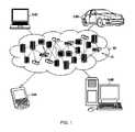
- FIG. 1illustrates a cloud computing environment according to an embodiment of the present invention.
- illustrative cloud computing environment 50comprises one or more cloud computing nodes 10 with which local computing devices used by cloud consumers, such as, for example, personal digital assistant (PDA) or cellular telephone 54 A, desktop computer 54 B, laptop computer 54 C and/or automobile computer system 54 N may communicate.
- Computing nodes 10may communicate with one another. They may be grouped (not shown) physically or virtually, in one or more networks, such as, Private, Community, Public or Hybrid clouds as described hereinabove or a combination thereof.
- Thisallows cloud computing environment 50 to offer infrastructure, platforms and/or software as services for which a cloud consumer does not need to maintain resources on a local computing device.
- computing devices 54 A-N shown in FIG. 1are intended to be illustrative only and that computing nodes 10 and cloud computing environment 50 can communicate with any type of computerized device over any type of network and/or network addressable connection (e.g., using a web browser).
- FIG. 2illustrates abstraction model layers according to an embodiment of the present invention and comprises a set of functional abstraction layers provided by cloud computing environment 50 ( FIG. 1 ). It should be understood in advance that the components, layers and functions shown in FIG. 2 are intended to be illustrative only and embodiments of the present invention are not limited thereto. As depicted, the following layers and corresponding functions are provided:
- Hardware and software layer 60includes hardware and software components representing a hyper-converged infrastructure.
- hardware componentsinclude: mainframes 61 ; RISC (Reduced Instruction Set Computer) architecture based servers 62 ; servers 63 ; blade servers 64 ; storage devices 65 ; and networks and networking components 66 .
- Software componentscan include network application server software 67 and database software 68 .
- database software 68includes software as described with respect to FIGS. 3-9 for providing data-locality-aware task scheduling on the hyper-converged infrastructure.
- Virtualization layer 70provides an abstraction layer from which the following examples of virtual entities may be provided: virtual servers 71 ; virtual storage 72 ; virtual networks 73 , including virtual private networks; virtual applications and operating systems 74 ; and virtual clients 75 .
- virtual clients 75represent isolated user-space instances (i.e., containers) that, in conjunction with one or more components of database software 68 , facilitate data-locality-aware task scheduling, as described herein.
- management layer 80may provide the functions described below.
- Resource provisioning 81provides dynamic procurement of computing resources and other resources that are utilized to perform tasks within the cloud computing environment.
- Metering and Pricing 82provide cost tracking as resources are utilized within the cloud computing environment and billing or invoicing for consumption of these resources. In one example, these resources may include application software licenses.
- Securityprovides identity verification for cloud consumers and tasks, as well as protection for data and other resources.
- User portal 83provides access to the cloud computing environment for consumers and system administrators.
- Service level management 84provides cloud computing resource allocation and management such that required service levels are met.
- Service Level Agreement (SLA) planning and fulfillment 85provide pre-arrangement for and procurement of, cloud computing resources for which a future requirement is anticipated in accordance with an SLA.
- SLAService Level Agreement
- Workloads layer 90provides examples of functionality for which the cloud computing environment may be utilized. Examples of workloads and functions which may be provided from this layer include: mapping and navigation 91 ; software development and lifecycle management 92 ; virtual classroom education delivery 93 ; data analytics processing 94 ; transaction processing 95 ; and mobile desktop 96 .
- data analytics processing 94represents instances of analytical software generating jobs for which data-locality-aware task scheduling is provided for respective tasks, as described herein.
- FIG. 3is a functional block diagram illustrating a computing environment, in accordance with an embodiment of the present invention.
- FIG. 3is a functional block diagram illustrating computing environment 100 .
- Computing environment 100includes client 105 A, client 105 B, client 105 C, which are collectively referred to as clients 105 , and hyper-converged infrastructure 110 .
- Network 160communicatively connects clients 105 and hyper-converged infrastructure 110 .
- Hyper-converged infrastructure 110includes various resources and logic for hosting virtualized resources and storing computer data generated, at least in part, in response to operations of the hosted, virtualized resources.
- hyper-converged infrastructure 110includes virtualization logic 120 , parallel processing logic 130 , distributed file system 140 and physical nodes 150 .
- virtualization logic 120includes container logic 122 and container management logic 124
- parallel processing logic 130includes parallel processing logic application program interface (parallel processing logic API) 132 and scheduling logic 134
- distributed file system 140includes distributed file system application program interface (distributed file system API) 142 and connector logic 144
- physical nodes 150include data storage devices 152 and distributed database 154 .
- client 105 Ais a computing device that can be a standalone device, a server, a laptop computer, a tablet computer, a netbook computer, a personal computer (PC), or a desktop computer.
- client 105 Arepresents a computing system utilizing clustered computers and components to act as a single pool of seamless resources.
- client 105 Acan be any computing device or a combination of devices with access to hyper-converged infrastructure 110 via network 160 .
- Client 105 B and client 105 Care analogous to client 105 A.
- Client 105 A, client 105 B, and client 105 Care collectively referred to as clients 105 , and clients 105 can include one or more types of computing devices.
- Clients 105can include internal and external hardware components, as depicted and described in further detail with respect to FIG. 9 .
- clients 105are computing devices that provide, via network 160 , one or both of instructions and data to hyper-converged infrastructure 110 such that hyper-converged infrastructure 110 deploys virtualized resources on physical nodes 150 as described herein.
- Network 160can be, for example, a local area network (LAN), a wide area network (WAN) such as the Internet, or a combination of the two, and may include wired, wireless, fiber optic or any other connection known in the art.
- network 160can be any combination of connections and protocols that will support communications between clients 105 and hyper-converged infrastructure 110 , in accordance with an embodiment of the present invention.
- hyper-converged infrastructure 110represents a computing environment that includes physical and virtual resources for managing and deploying workloads on physical nodes 150 .
- Hyper-converged infrastructure 110is representative of cloud computing node(s) 10 in some embodiments of the present invention.
- physical nodes 150can represent commodity computing hardware and software that provides, at least in part, hyper-converged infrastructure 110 with characteristics that are associated with a hyper-converged framework, as will be understood by persons having ordinary skill in the art.
- physical nodes 150represent a plurality of networked computing resources, wherein each node can be a standalone device, a server, a laptop computer, a tablet computer, a netbook computer, a personal computer (PC), a desktop computer, a personal digital assistant (PDA), a smart phone, or any programmable electronic device capable of executing tasks in accordance with data-locality-aware task scheduling, as described herein.
- one or more nodes of physical nodes 150represents a computing system utilizing clustered computers and components to act as a single pool of seamless resources.
- each node of physical nodes 150is a computing resource that is capable of executing tasks in accordance with data-locality-aware task scheduling, as described herein.
- Each node of physical nodes 150can include components as described with respect to FIG. 9 .
- physical nodes 150are communicatively connected via a dedicated inter-node network (not shown) such as a local area network (LAN), a wide area network (WAN) such as the Internet, or a combination of the two.
- the network connecting physical nodes 150can include wired, wireless, fiber optic or any other connection known in the art.
- hyper-converged infrastructure 110includes additional computing resources (not shown) to manage physical nodes 150 and provide an interface for clients 105 (i.e., one or more management nodes).
- data storage devices 152represent a collection of computer readable data storage devices.
- Data storage devices 152can include one or more hard disk drives, one or more solid-state drives, one or more tape drives, one or more optical disc drives, or any combination of the aforementioned data storage devices or any other type of data storage device known in the art.
- each data storage device of data storage devices 152is associated with a respective node of physical nodes 150 .
- one or more data storage devicesare directly attached to respective nodes of physical nodes 150 .
- one or more data storage devicesare communicatively connected to respective nodes of physical nodes 150 via a storage area network (SAN) or as network-attached-storage (NAS).
- SANstorage area network
- NASnetwork-attached-storage
- Distributed database 154is a distributed data repository that instances of parallel processing logic 130 can read from and/or write to in order to execute, in parallel, tasks associated with jobs received from one or more clients of clients 105 .
- distributed database 154can be written to and read by programs and entities outside of computing environment 100 in order to populate the repository with data.
- hyper-converged infrastructure 110utilizes distributed file system 140 to read and write data and/or metadata to distributed database 154 .
- distributed file system 140advantageously provides “striping” and replication of data over physical nodes 150 and respective data storage devices to respectively decrease read/write latencies and increase resiliency, as discussed in greater detail with respect to FIGS. 7A and 7B .
- distributed file system 140is a portable operating system interface (POSIX) compliant distributed and/or clustered file system.
- POSIXportable operating system interface
- distributed file system 140is a file system that is mounted directly on physical nodes 150 and provides one or more networked nodes with concurrent access to files stored distributed over the networked nodes.
- distributed file system API 142receives requests for data and/or metadata associated with information stored in distributed database 154 and connector logic 144 facilitates, at least in part, data-locality-aware task scheduling, as described herein.
- hyper-converged infrastructure 110utilizes virtualization logic 120 to provide containers in which instances of parallel processing logic 130 can execute, as described herein.
- virtualization logic 120represents logic for providing and managing isolated user-space environments on physical nodes 150 (i.e., operating-system-level virtualization on physical nodes 150 ).
- virtualization logic 120includes container logic 122 and container management logic 124 .
- Container logic 122is logic that provides an abstracted user-space over operating system kernels of physical nodes 150 .
- Each node of physical nodes 150can store an instance of container logic 122 and execute container logic 122 to provide one or more respective user-spaces (i.e., containers) to applications executing on hyper-converged infrastructure 110 .
- container logic 122is any type of logic for providing and managing isolated user-space environment on physical nodes 150 .
- container management logic 124represents logic for managing the deployment of containers among physical nodes 150 , as will be discussed in greater detail with respect to FIGS. 4-8 .
- physical nodes 150include one or more “management” nodes that manage the deployment of containers on physical nodes 150 .
- a management node executing container management logic 124can deploy a plurality of nodes on hyper-converged infrastructure 110 , organize the deployed nodes into clusters of containers (i.e., virtualized resource clusters), and generate data and/or metadata to facilitate data-locality-aware task scheduling, as described herein.
- clusters of containersi.e., virtualized resource clusters
- hyper-converged infrastructure 110utilizes parallel processing logic 130 to advantageously execute jobs submitted by clients 105 via instances of parallel processing logic 130 executing within respective containers on physical nodes 150 .
- parallel processing logic 130provides a logical framework that includes features for dividing jobs received from clients 105 into tasks, distributing the tasks among instances of parallel processing logic 130 executing within respective containers on physical nodes 150 , executing the distributed tasks in parallel, and storing any resulting data and/or metadata to, at least in part, distributed database 154 on data storage devices 152 .
- instances of parallel processing logic 130can execute within respective containers that are virtualized, via container logic 122 , on respective nodes of physical nodes 150 .
- parallel processing logic 130includes parallel processing logic API 132 to, at least in part, facilitate data-locality-aware task scheduling, as described herein. Because virtualization logic 120 provides at least one layer of abstraction between parallel processing logic 130 and (i) the underlying operating-system running on physical nodes 150 and (ii) the file system used to store data and/or metadata on data storage devices 152 (i.e., distributed file system 140 ), parallel processing logic 130 can utilize a virtual file system. In general, parallel processing logic 130 is, at least in part, logic that utilizes a virtualized, distributed file system to store data (e.g., a data-set associated with a parallel processing job) when executing within containers deployed on hyper-converged infrastructure 110 . As described herein, parallel processing logic API 132 can, in conjunction with connector logic 144 and distributed file system API 142 , provide a bridge between a virtualized, distributed file system and distributed file system 140 .
- parallel processing logic API 132can, in conjunction with connector logic 144 and distributed file system API 142 , provide a
- parallel processing logic 130includes scheduling logic 134 .
- scheduling logic 134represents logic for scheduling tasks on instances of parallel processing logic 130 executing within respective containers on physical nodes 150 .
- each cluster of nodes in physical nodes 150includes a “master” node that executes scheduling logic 134 and schedules tasks among respective “worker” nodes.
- the previously described management nodeexecutes scheduling logic 134 for each cluster of nodes in physical nodes 150 (i.e., each virtual resource cluster) and schedules jobs among the clusters of nodes and tasks within each cluster of nodes.
- scheduling logic 134interfaces with parallel processing logic 130 but is not integrated with parallel processing logic 130 .
- scheduling logic 134To reduce network traffic among physical nodes 150 during execution of a job, it is advantageous for scheduling logic 134 to schedule tasks based, at least in part, on the locality of the data and/or metadata required to execute respective tasks. As previously stated, this type of task scheduling is herein referenced as “data-locality-aware” scheduling. When tasks are scheduled using data-locality-aware task scheduling, to the extent possible, task scheduling logic 134 schedules tasks such that the instances of parallel processing logic 130 that are scheduled to execute the respective tasks run on the physical nodes that store, or are closest to, the data and/or metadata required to execute the respective tasks.
- Data-locality-aware task schedulingrequires that scheduling logic 134 have the ability to obtain data-locality information (i.e., identify how the information stored in distributed database 154 data is distributed over physical nodes 150 ). If, however, parallel processing logic 130 is configured to utilize a virtual file system, the ability to obtain data-locality information from distributed file system 140 can be lost.
- connector logic 144facilitates data-locality-aware task scheduling, at least in part, by interfacing with parallel processing logic API 132 and distributed file system API 142 to provide scheduling logic 134 with data-locality information, as described with respect to FIGS. 4-8 .
- FIG. 4is a block diagram depicting two virtualized resource clusters that are deployed on a plurality of physical nodes of a hyper-converged infrastructure, in accordance with an embodiment of the present invention.
- Various embodiments of the present inventioninclude different numbers and arrangements of physical nodes, virtualized containers, and virtualized resource clusters than the embodiment depicted in FIG. 4 .
- container management logic 124deploys six containers over three nodes of physical nodes 150 : node 232 (referenced herein as “node 1 ”); node 234 (referenced herein as “node 2 ”); and node 236 (referenced herein as “node 2 ”).
- Node 1hosts container 211 (referenced herein as “container 1 ”) and container 222 (referenced herein as “container 2 ”).
- Node 2hosts container 213 (referenced herein as “container 3 ”) and container 224 (referenced herein as “container 4 ”).
- Node 3hosts container 215 (referenced herein as “container 5 ”) and container 226 (referenced herein as “container 6 ”).
- Virtualized resource cluster 210(referenced herein as “virtualized resource cluster 1 ”) comprises containers 1 , 3 , and 5
- virtualized resource cluster 220(referenced herein as “virtualized resource cluster 2 ”) comprises containers 2 , 4 , and 6 .
- a respective instance of parallel processing logic 130can execute in each of containers 1 , 2 , 3 , 4 , 5 , and 6 such that the instances executing within containers 1 , 3 , 5 execute tasks associated with a first job scheduled on virtualized resource cluster 1 and the instances executing within containers 2 , 4 , and 6 execute tasks associated with a second job scheduled on virtualized resource cluster 2 .
- scheduling logic 134it is advantageous for scheduling logic 134 to schedule tasks on the instances of parallel processing logic 130 executing within containers 1 , 2 , 3 , 4 , 5 , and 6 utilizing data-locality-aware task scheduling.
- FIG. 1In the embodiment depicted in FIG.
- a preferred implementation of data-locality-aware task schedulingwould indicate that (i) node 1 stores data and/or metadata required to execute tasks scheduled on the respective instances of parallel processing logic 130 executing within containers 1 and 2 , (ii) node 2 stores data and/or metadata required to execute tasks scheduled on the respective instances of parallel processing logic 130 executing within container 3 and 4 , and (iii) node 3 stores data and/or metadata required to execute tasks scheduled on the respective instances of parallel processing logic 130 executing within containers 5 and 6 .
- FIG. 5depicts, in part, how connector logic 144 facilitates data-locality-aware task scheduling with respect to virtualizes resource cluster 1 .
- FIG. 5is a block diagram depicting connectors that, to facilitate data-locality-aware task scheduling, interface with instances of an application executing within containers deployed on a hyper-converged infrastructure, in accordance with an embodiment of the present invention. More specifically, FIG. 5 depicts an embodiment in which virtualized resource cluster 1 , as depicted in FIG. 4 , interfaces with distributed file system 140 , which manages data and/or metadata stored on nodes 1 , 2 , and 3 of physical nodes 150 . As depicted in FIG.
- connector logic 122deploys connector 241 (referenced herein as “connector 1 ”), connector 243 (referenced herein as “connector 3 ”), and connector 245 (referenced herein as “connector 5 ”) to monitor the network (e.g., the 10.10.1.X network referenced in FIG. 5 ) that distributed file system 140 uses to transfer data among data storage devices 152 of physical nodes 150 .
- the networke.g., the 10.10.1.X network referenced in FIG. 5
- connectors 1 , 3 , and 5respectively interface with containers 1 , 3 , and 5 using virtual network addresses of the respective containers (e.g., the addresses on the 192.168.1.X network referenced in FIG. 5 ).
- connector logic 144provides each of connectors 1 , 3 , and 5 , in response to receiving a query for data-locality information from an instance of scheduling logic 134 , with data-locality information from distributed file system 140 over the 10.10.1.X network. Additionally, scheduling logic 134 translates the data-locality information in order to schedule tasks among the containers of virtualized resource cluster 1 , as discussed in greater detail with respect to FIGS. 7A, 7B, and 8 .
- While instances of parallel processing logic 130respectively execute scheduled tasks within containers 1 , 3 , 5 , connectors 1 , 3 , and 5 interface with respective instances of parallel processing logic API 132 and distributed file system API 142 to provide containers 1 , 3 , and 5 with the ability to complete input/output (I/O) operations via distributed file system 140 .
- parallel processing logic API 132and distributed file system API 142 to provide containers 1 , 3 , and 5 with the ability to complete input/output (I/O) operations via distributed file system 140 .
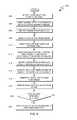
- FIG. 6Ais a flowchart depicting operations for generating a container-instance mapping table, in accordance with an embodiment of the present invention. More specifically, FIG. 6A is a flowchart depicting operations 300 of container management logic 124 within computing environment 100 .
- Embodiments of the present inventionutilize a container-instance mapping table to associate containers with the physical nodes on which the containers are deployed.
- a container-instance mapping tablewill be discussed with respect to FIG. 6B .
- parallel processing logic 130requests that virtualization logic 120 deploy containers on physical nodes 150 in response to hyper-converged infrastructure 110 receiving a job from one of clients 105 .
- container management logic 124identifies one or more target physical nodes (i.e., nodes on which container management logic 124 will deploy containers) from among physical nodes 150 ( 302 ). In various embodiments, container management logic identifies target physical nodes based on the availability of various computing resources among physical nodes 150 , computing resources that the client associated with the requested job is authorized to use, or other factor(s) or any combination of factors, as will be understood by persons having ordinary skill in the art.
- container management logic 124prepares one or more container instances for deployment on the one or more target physical nodes ( 304 ).
- preparing the one or more container instancesincludes determining how the target physical nodes are to allocate, to respective containers, processor resources, memory resources, network resources, libraries, or other computing resource(s) or any combination of resources, as will be understood by persons having ordinary skill in the art.
- container management logic 124deploys the one or more container instances on respective target physical nodes ( 306 ). In various embodiments, container management logic 124 deploys the one or more container instances by, at least in part, issuing instructions to the respective target physical nodes that instruct instances of virtualization logic 120 executing thereon to initialize containers in accordance with properties identified in operation 304 .
- container management logic 124generates or updates a container-instance mapping table ( 308 ). In some embodiments, container management logic 124 generates the container-instance mapping table based on the identities of the target physical node(s) and the identities of the respective container(s) deployed thereon, as determined via operations 300 .
- container management logic 124or another logical component of hyper-converged infrastructure 110 , generates or updates a container-instance mapping table in operation 308 by executing one or more scripts on physical nodes 150 to (i) identify each node of physical nodes 150 and (ii) monitor and/or log processes executed by respective, hosted containers (e.g., scripts utilizing commanded including “ps-elf” and “grep” Linux commands with respect to containers) in order to identify the containers based on an associated IP address (e.g., an IP address on the 192.168.1.X network referenced in FIG. 5 ), a host name, or another identifier or combination of identifiers returned by the one or more scripts.
- hosted containerse.g., scripts utilizing commanded including “ps-elf” and “grep” Linux commands with respect to containers
- IP addresse.g., an IP address on the 192.168.1.X network referenced in FIG. 5
- host namee.g., an IP address on the
- FIG. 6Bis an example of a container-instance mapping table, in accordance with an embodiment of the present invention. More specifically, FIG. 6B depicts container-instance mapping table 310 , which associates the containers depicted in FIG. 4 with the physical nodes on which they are deployed.
- Container-instance mapping table 310includes column 312 , which indicates node identifiers (ID(s)) IDs, column 314 , which indicates containers IDs, column 316 , which indicates Container IP addresses based on the 192.168.1.X network depicted in FIG. 5 , column 318 , which indicates host names, and column 320 , which indicates the directories (i.e., directory IDs associated with the respective virtualized resource clusters) that are associated with the various containers.
- ID(s)node identifiers
- column 314which indicates containers IDs
- column 316which indicates Container IP addresses based on the 192.168.1.X network depicted in FIG. 5
- column 318which indicates host names
- Container-instance mapping table 310represents just one example of a container-instance mapping table, and other embodiments of the present invention can utilize container mapping tables that include additional and/or different type(s) of information and/or that are organized in different manners without departing from the scope of the present invention.
- container-instance mapping tablesfacilitate, at least in a part, data-locality-aware task scheduling by enabling connector logic 144 to provide data-locality information to instance(s) of parallel processing logic 130 and instance(s) of scheduling logic 134 executing within containers on physical nodes 150 .
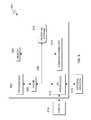
- FIG. 7Ais a block diagram depicting an example of data distributed over a plurality of nodes based on a distributed file system, in accordance with an embodiment of the present invention. More specifically, FIG. 7A depicts a first file and a second file that are distributed over six nodes of physical nodes 150 , in accordance with distributed file system 140 . In the embodiment depicted in FIG.
- distributed file system 140distributes files over six nodes of physical nodes 150 : node 232 (referenced herein as “node 1 ”); node 234 (referenced herein as “node 2 ”); node 236 (referenced herein as “node 3 ”); node 238 (referenced herein as “node 4 ”); node 240 (referenced herein as “node 5 ”); and node 242 (referenced herein as “node 6 ”).
- distributed file system 140stripes files into blocks based on a data block size, replicates each block three times, and, for each block, distributes the replicated blocks across three nodes of physical nodes 150 in the embodiment depicted in FIG. 7A .
- FIG. 7AIn FIG.
- a first fileis striped into two blocks and each block is replicated three times such that: a first replica of the first block is represented as “F 1 -B 1 -R 1 ” on node 1 ; a second replica of the first block is represented as “F 1 -B 1 -R 2 ” on node 2 ; a third replica of the first block is represented as “F 1 -B 1 -R 3 ” on node 4 ; a first replica of the second block is represented as “F 1 -B 2 -R 1 ” on node 2 ; a second replica of the second block is represented as “F 1 -B 2 -R 2 ” on node 3 ; and a third replica of the second block is represented as “F 1 -B 2 -R 3 ” on node 4 .
- a second fileis striped into three blocks (i.e., the second file is larger than the first file) and each block is replicated three times such that: a first replica of the first block is represented as “F 2 -B 1 -R 1 ” on node 1 ; a second replica of the first block is represented as “F 2 -B 1 -R 2 ” on node 4 ; a third replica of the first block is represented as “F 2 -B 1 -R 3 ” on node 6 ; a first replica of the second block is represented as “F 2 -B 2 -R 1 ” on node 3 ; a second replica of the second block is represented as “F 2 -B 2 -R 2 ” on node 5 ; a third replica of the second block is represented as “F 2 -B 2 -R 3 ” on node 6 ; a first replica of the third block is represented as “F 2 -B 3 -R 1 ” on node 2 ; a second replica of the first
- distributed file system 140maintains a block-location mapping table that describes how files are distributed among physical nodes 150 to facilitate, at least in part, data-locality-aware task scheduling of tasks on hyper-converged infrastructure 110 , as described herein.
- FIG. 7Bis a block-location mapping table that describes the distribution of the blocks depicted in FIG. 7A .
- FIG. 7Bis an example of a block-location mapping table, in accordance with an embodiment of the present invention. More specifically, block-location mapping table 400 describes the distribution of the blocks depicted in FIG. 7A .
- Block-location mapping table 400includes column 402 , which indicates the block ID of each block managed by distributed file system 140 , column 404 , which indicates the node IDs of the physical nodes that store the first replica of each block (i.e., the node IDs referenced in container-instance mapping table that maps the containers to the physical nodes on which they are deployed), column 406 , which indicates the node IDs of the physical nodes that store the second replica of each block, and column 408 , which indicates the node IDs of the physical nodes that store the third replica of each block.
- Block-location mapping table 400is just one example of a block-location mapping table, and other embodiments of the present invention can utilize block-location mapping tables that include additional and/or different type(s) of information than block-location mapping table 400 and that are organized differently than block-location mapping table 400 without departing from the scope of the present invention.
- block-location mapping tablesfacilitate, at least in a part, data-locality-aware task scheduling by enabling connector logic 144 to provide data-locality information to instances of parallel processing logic 130 and instance(s) of scheduling logic 134 executing within containers on physical nodes 150 .
- FIG. 8is a flowchart depicting operations for facilitating data-locality-aware task scheduling on a hyper-converged infrastructure, in accordance with an embodiment of the present invention. More specifically, FIG. 8 is a flowchart depicting operations 500 of connector logic 144 on hyper-converged infrastructure 110 in computing environment 100 .
- Connector logic 144identifies an I/O request from scheduling logic 134 .
- connector logic 144identifies data referenced in the I/O request either from the I/O request directly or by querying one or more resources of hyper-converged infrastructure 110 for such data ( 502 ).
- the I/O requestsrepresent a plurality of “map” input steps or a plurality of “reduce” output steps of a MapReduce job.
- the I/O requestcan relate to any type of I/O operation on data storage devices 152 that can be divided into tasks that are distributed among various nodes of physical nodes 150 and executed in parallel. In the embodiment depicted in FIG.
- hyper-converged infrastructureincludes multiple virtualized resource clusters that can submit I/O requests via respective instances of scheduling logic 134 simultaneously. Accordingly, connector logic 144 can execute multiple instances of operations 500 , in parallel, to facilitate data-locality-aware task scheduling on a plurality of virtualized resource clusters of hyper-converged infrastructure 110 .
- connector logic 144queries distributed file system API 142 for one or more block-location mapping tables based on the referenced data (e.g., based on one or more file and/or block identifiers referenced in the I/O request; 504 ). As discussed with respect to FIG. 7B , the block-location mapping table(s) can identify the physical nodes that store each replica of each block of data referenced in the I/O request. In some embodiments, connector logic 144 scans any block-location mapping tables identified as a result of querying distributed file system 140 ( 504 ) to generate, or otherwise identify, a queue of blocks that represents the data referenced in the I/O request ( 506 ).
- distributed file system 140can provide connector logic 144 with data-locality information for the data referenced in the I/O request, this data-locality information is transparent to scheduling logic 134 executing within an abstracted user-space (i.e., a container).
- scheduling logic 134executing within an abstracted user-space (i.e., a container).
- connector logic 144maps each block of data to one or more respective physical nodes that store the block (e.g., the physical nodes that store each replica of the block of data) and maps the physical nodes to the containers deployed thereon.
- connector logic 144selects a block of data from the queue of blocks that represents the data referenced in the I/O request ( 508 ) and identifies the physical node(s) that store the selected block of data (e.g., the physical nodes that store replicas of the block of data) based on the identified block-location mapping table(s).
- the identified physical node(s)To determine how containers are deployed on the identified physical node(s) connector logic 144 queries for one or more container-instance mapping tables that describe how containers are presently deployed on physical nodes 150 ( 510 ). Connector logic 144 scans any container-instance mapping tables identified as a result of the query ( 512 ).
- connector logic 144scans the identified container-instance mapping table(s) using one or more identifiers that are associated with the physical nodes that store the selected block of data. If, for example, the selected block of data is the first block of the first file depicted in FIGS.
- connector logic 144can scan block-location mapping table 400 to determine that “node 1 ” (i.e., node 1 ) stores the first replica (i.e., F 1 _B 1 _R 1 ), that “node 2 ” (i.e., node 2 ) stores the second replica (i.e., F 1 _B 1 _R 2 ), and that “Node 4 ” (i.e., node 4 ) stores the third replica (i.e., F 1 _B 1 _R 3 ).
- Connector logic 144can then scan a container-instance mapping table that is analogous to container-instance mapping table 310 using the node IDs “Node 1 ”, “Node 2 ”, and “Node 4 ” to identify the containers that are deployed on node 1 , node 2 , and node 4 .
- connector logic 144identifies containers having data-locality with the selected block of data ( 514 ).
- container-instance mapping table(s)512
- connector logic 144identifies containers having data-locality with the selected block of data ( 514 ).
- Scanning container-instance mapping table 310 for “Node 1 ,” for example,will identify both “Node 1 _contain 1 ” (i.e., container 1 ) and “Node 1 _contain 2 ” (i.e., container 2 ) as containers that are deployed on node 1 .
- “Node 1 _contain 1 ”i.e., container 1
- “Node 1 _contain 2 ”i.e., container 2
- virtual resource cluster 1 and virtual resource cluster 2are deployed on hyper-converged infrastructure 110 , as shown in container-instance mapping table 310 by the association between “Node 1 _contain 1 ” (i.e., container 1 ) and “Node 1 _contain 2 ” (i.e., container 2 ) and the directories “/cluster 1 ” (i.e., virtualized resource cluster 1 ) and “/cluster 2 ” (i.e., virtualized resource cluster 2 ) respectively.
- connector logic 144is able to identify the container that submitted, via scheduling logic 134 , the I/O request.
- Connector logic 144can identify “valid container(s)” having data-locality with the selected block of data using the identity of the container that submitted the I/O request and one or more container-instance mapping tables ( 516 ). If, for example, connector logic 144 received the I/O request from container 1 via connecter 1 , as depicted in FIG.
- connector logic 144can identify “Node 1 _contain 1 ” (i.e., container 1 ), “Node 2 _contain 1 ” (i.e., container 3 ), and notionally, “Node 4 _contain 1 ” (i.e., a node ID representing a notional “container 7 ” that is associated with the “/cluster 1 ” directory) as valid containers having data-locality with the first block of the first file (i.e., File 1 _Block 1 ).
- Node 1 _contain 2i.e., container 2
- Node 2 _contain 2i.e., container 4
- connector logic 144generates and updates a list of valid containers and the associated blocks of data for the data referenced in the I/O request ( 518 ).
- connector logic 144To identify valid containers having data locality with each block of data associated with the I/O request, connector logic 144 removes the selected data block from the queue ( 520 ), and in response to determining that blocks of data remain in the queue (decision 522 , YES branch), connector logic 144 selects another block of data from the queue and performs another iteration of operations 508 - 520 . If connector logic 144 determines that no data blocks remain in the queue (decision 522 , NO branch), connector logic 144 provides, via parallel processing logic API 132 , the list of valid containers having data-locality with the data referenced in the I/O request to the instance of scheduling logic 134 that submitted the I/O request ( 524 ).
- scheduling logic 134can identify, for each task associated with the I/O request, one or more containers that have data-locality with the data required to execute the respective task. Scheduling logic 134 can therefore schedule tasks over containers deployed on physical nodes 150 based on data-locality aware task scheduling.
- FIG. 9is a block diagram of components of a computing device, generally designated 600 , in accordance with an embodiment of the present invention.
- computing system 600is representative of one or more nodes of physical nodes 150 within computing environment 100 , in which case computing system includes one or more of the features described with respect to FIGS. 3-8 .
- FIG. 9provides only an illustration of one implementation and does not imply any limitations with regard to the environments in which different embodiments may be implemented. Many modifications to the depicted environment may be made.
- Computing system 600includes processor(s) 602 , cache 606 , memory 604 , persistent storage 610 , input/output (I/O) interface(s) 612 , communications unit 614 , and communications fabric 608 .
- Communications fabric 608provides communications between cache 606 , memory 604 , persistent storage 610 , communications unit 614 , and input/output (I/O) interface(s) 612 .
- Communications fabric 608can be implemented with any architecture designed for passing data and/or control information between processors (such as microprocessors, communications and network processors, etc.), system memory, peripheral devices, and any other hardware components within a system.
- processorssuch as microprocessors, communications and network processors, etc.
- Communications fabric 608can be implemented with one or more buses or a crossbar switch.
- Memory 604 and persistent storage 610are computer readable storage media.
- memory 604includes random access memory (RAM).
- RAMrandom access memory
- memory 604can include any suitable volatile or non-volatile computer readable storage media.
- Cache 606is a fast memory that enhances the performance of processor(s) 602 by holding recently accessed data, and data near recently accessed data, from memory 604 .
- persistent storage 610includes a magnetic hard disk drive.
- persistent storage 610can include a solid state hard drive, a semiconductor storage device, read-only memory (ROM), erasable programmable read-only memory (EPROM), flash memory, or any other computer readable storage media that is capable of storing program instructions or digital information.
- the media used by persistent storage 610may also be removable.
- a removable hard drivemay be used for persistent storage 610 .
- Other examplesinclude optical and magnetic disks, thumb drives, and smart cards that are inserted into a drive for transfer onto another computer readable storage medium that is also part of persistent storage 610 .
- Communications unit 614in these examples, provides for communications with other data processing systems or devices.
- communications unit 614includes one or more network interface cards.
- Communications unit 614may provide communications through the use of either or both physical and wireless communications links.
- Program instructions and data used to practice embodiments of the present inventionmay be downloaded to persistent storage 610 through communications unit 614 .
- I/O interface(s) 612allows for input and output of data with other devices that may be connected to computer system 600 .
- I/O interface(s) 612may provide a connection to external device(s) 616 such as a keyboard, keypad, a touch screen, and/or some other suitable input device.
- External device(s) 616can also include portable computer readable storage media such as, for example, thumb drives, portable optical or magnetic disks, and memory cards.
- Software and data used to practice embodiments of the present inventioncan be stored on such portable computer readable storage media and can be loaded onto persistent storage 610 via I/O interface(s) 612 .
- I/O interface(s) 612also connect to display 618 .
- Display 618provides a mechanism to display or present data to a user and may be, for example, a computer monitor.
- the present inventionmay be a system, a method, and/or a computer program product at any possible technical detail level of integration
- the computer program productmay include a computer readable storage medium (or media) having computer readable program instructions thereon for causing a processor to carry out aspects of the present invention
- the computer readable storage mediumcan be a tangible device that can retain and store instructions for use by an instruction execution device.
- the computer readable storage mediummay be, for example, but is not limited to, an electronic storage device, a magnetic storage device, an optical storage device, an electromagnetic storage device, a semiconductor storage device, or any suitable combination of the foregoing.
- a non-exhaustive list of more specific examples of the computer readable storage mediumincludes the following: a portable computer diskette, a hard disk, a random access memory (RAM), a read-only memory (ROM), an erasable programmable read-only memory (EPROM or Flash memory), a static random access memory (SRAM), a portable compact disc read-only memory (CD-ROM), a digital versatile disk (DVD), a memory stick, a floppy disk, a mechanically encoded device such as punch-cards or raised structures in a groove having instructions recorded thereon, and any suitable combination of the foregoing.
- RAMrandom access memory
- ROMread-only memory
- EPROM or Flash memoryerasable programmable read-only memory
- SRAMstatic random access memory
- CD-ROMcompact disc read-only memory
- DVDdigital versatile disk
- memory sticka floppy disk
- a mechanically encoded devicesuch as punch-cards or raised structures in a groove having instructions recorded thereon
- a computer readable storage mediumis not to be construed as being transitory signals per se, such as radio waves or other freely propagating electromagnetic waves, electromagnetic waves propagating through a waveguide or other transmission media (e.g., light pulses passing through a fiber-optic cable), or electrical signals transmitted through a wire.
- Computer readable program instructions described hereincan be downloaded to respective computing/processing devices from a computer readable storage medium or to an external computer or external storage device via a network, for example, the Internet, a local area network, a wide area network and/or a wireless network.
- the networkmay comprise copper transmission cables, optical transmission fibers, wireless transmission, routers, firewalls, switches, gateway computers and/or edge servers.
- a network adapter card or network interface in each computing/processing devicereceives computer readable program instructions from the network and forwards the computer readable program instructions for storage in a computer readable storage medium within the respective computing/processing device.
- Computer readable program instructions for carrying out operations of the present inventionmay be assembler instructions, instruction-set-architecture (ISA) instructions, machine instructions, machine dependent instructions, microcode, firmware instructions, state-setting data, configuration data for integrated circuitry, or either source code or object code written in any combination of one or more programming languages, including an object oriented programming language such as Smalltalk, C++, or the like, and procedural programming languages, such as the “C” programming language or similar programming languages.
- the computer readable program instructionsmay execute entirely on the user's computer, partly on the user's computer, as a stand-alone software package, partly on the user's computer and partly on a remote computer or entirely on the remote computer or server.
- the remote computermay be connected to the user's computer through any type of network, including a local area network (LAN) or a wide area network (WAN), or the connection may be made to an external computer (for example, through the Internet using an Internet Service Provider).
- electronic circuitryincluding, for example, programmable logic circuitry, field-programmable gate arrays (FPGA), or programmable logic arrays (PLA) may execute the computer readable program instructions by utilizing state information of the computer readable program instructions to personalize the electronic circuitry, in order to perform aspects of the present invention.
- These computer readable program instructionsmay be provided to a processor of a general purpose computer, special purpose computer, or other programmable data processing apparatus to produce a machine, such that the instructions, which execute via the processor of the computer or other programmable data processing apparatus, create means for implementing the functions/acts specified in the flowchart and/or block diagram block or blocks.
- These computer readable program instructionsmay also be stored in a computer readable storage medium that can direct a computer, a programmable data processing apparatus, and/or other devices to function in a particular manner, such that the computer readable storage medium having instructions stored therein comprises an article of manufacture including instructions which implement aspects of the function/act specified in the flowchart and/or block diagram block or blocks.
- the computer readable program instructionsmay also be loaded onto a computer, other programmable data processing apparatus, or other device to cause a series of operational steps to be performed on the computer, other programmable apparatus or other device to produce a computer implemented process, such that the instructions which execute on the computer, other programmable apparatus, or other device implement the functions/acts specified in the flowchart and/or block diagram block or blocks.
- each block in the flowchart or block diagramsmay represent a module, segment, or portion of instructions, which comprises one or more executable instructions for implementing the specified logical function(s).
- the functions noted in the blocksmay occur out of the order noted in the Figures.
- two blocks shown in successionmay, in fact, be executed substantially concurrently, or the blocks may sometimes be executed in the reverse order, depending upon the functionality involved.
Landscapes
- Engineering & Computer Science (AREA)
- Software Systems (AREA)
- Theoretical Computer Science (AREA)
- Physics & Mathematics (AREA)
- General Engineering & Computer Science (AREA)
- General Physics & Mathematics (AREA)
- Information Retrieval, Db Structures And Fs Structures Therefor (AREA)
Abstract
Description
Claims (20)
Priority Applications (1)
| Application Number | Priority Date | Filing Date | Title |
|---|---|---|---|
| US15/232,076US10540212B2 (en) | 2016-08-09 | 2016-08-09 | Data-locality-aware task scheduling on hyper-converged computing infrastructures |
Applications Claiming Priority (1)
| Application Number | Priority Date | Filing Date | Title |
|---|---|---|---|
| US15/232,076US10540212B2 (en) | 2016-08-09 | 2016-08-09 | Data-locality-aware task scheduling on hyper-converged computing infrastructures |
Publications (2)
| Publication Number | Publication Date |
|---|---|
| US20180046503A1 US20180046503A1 (en) | 2018-02-15 |
| US10540212B2true US10540212B2 (en) | 2020-01-21 |
Family
ID=61158985
Family Applications (1)
| Application Number | Title | Priority Date | Filing Date |
|---|---|---|---|
| US15/232,076Expired - Fee RelatedUS10540212B2 (en) | 2016-08-09 | 2016-08-09 | Data-locality-aware task scheduling on hyper-converged computing infrastructures |
Country Status (1)
| Country | Link |
|---|---|
| US (1) | US10540212B2 (en) |
Cited By (46)
| Publication number | Priority date | Publication date | Assignee | Title |
|---|---|---|---|---|
| US10771344B2 (en)* | 2018-12-21 | 2020-09-08 | Servicenow, Inc. | Discovery of hyper-converged infrastructure devices |
| US10970107B2 (en)* | 2018-12-21 | 2021-04-06 | Servicenow, Inc. | Discovery of hyper-converged infrastructure |
| US10979510B2 (en)* | 2015-09-10 | 2021-04-13 | International Business Machines Corporation | Handling multi-pipe connections |
| US20220237190A1 (en)* | 2021-01-25 | 2022-07-28 | OneTrust, LLC | Systems and methods for discovery, classification, and indexing of data in a native computing system |
| US11461500B2 (en) | 2016-06-10 | 2022-10-04 | OneTrust, LLC | Data processing systems for cookie compliance testing with website scanning and related methods |
| US11475136B2 (en) | 2016-06-10 | 2022-10-18 | OneTrust, LLC | Data processing systems for data transfer risk identification and related methods |
| US11481710B2 (en) | 2016-06-10 | 2022-10-25 | OneTrust, LLC | Privacy management systems and methods |
| US11488085B2 (en) | 2016-06-10 | 2022-11-01 | OneTrust, LLC | Questionnaire response automation for compliance management |
| US11520928B2 (en) | 2016-06-10 | 2022-12-06 | OneTrust, LLC | Data processing systems for generating personal data receipts and related methods |
| US11533315B2 (en) | 2021-03-08 | 2022-12-20 | OneTrust, LLC | Data transfer discovery and analysis systems and related methods |
| US11546661B2 (en) | 2021-02-18 | 2023-01-03 | OneTrust, LLC | Selective redaction of media content |
| US11544405B2 (en) | 2016-06-10 | 2023-01-03 | OneTrust, LLC | Data processing systems for verification of consent and notice processing and related methods |
| US11544667B2 (en) | 2016-06-10 | 2023-01-03 | OneTrust, LLC | Data processing systems for generating and populating a data inventory |
| US11556672B2 (en) | 2016-06-10 | 2023-01-17 | OneTrust, LLC | Data processing systems for verification of consent and notice processing and related methods |
| US11558429B2 (en) | 2016-06-10 | 2023-01-17 | OneTrust, LLC | Data processing and scanning systems for generating and populating a data inventory |
| US11562078B2 (en) | 2021-04-16 | 2023-01-24 | OneTrust, LLC | Assessing and managing computational risk involved with integrating third party computing functionality within a computing system |
| US11586700B2 (en) | 2016-06-10 | 2023-02-21 | OneTrust, LLC | Data processing systems and methods for automatically blocking the use of tracking tools |
| US11593523B2 (en) | 2018-09-07 | 2023-02-28 | OneTrust, LLC | Data processing systems for orphaned data identification and deletion and related methods |
| US11615192B2 (en) | 2020-11-06 | 2023-03-28 | OneTrust, LLC | Systems and methods for identifying data processing activities based on data discovery results |
| US11620142B1 (en) | 2022-06-03 | 2023-04-04 | OneTrust, LLC | Generating and customizing user interfaces for demonstrating functions of interactive user environments |
| US11636171B2 (en) | 2016-06-10 | 2023-04-25 | OneTrust, LLC | Data processing user interface monitoring systems and related methods |
| US11645418B2 (en) | 2016-06-10 | 2023-05-09 | OneTrust, LLC | Data processing systems for data testing to confirm data deletion and related methods |
| US11645353B2 (en) | 2016-06-10 | 2023-05-09 | OneTrust, LLC | Data processing consent capture systems and related methods |
| US11651402B2 (en) | 2016-04-01 | 2023-05-16 | OneTrust, LLC | Data processing systems and communication systems and methods for the efficient generation of risk assessments |
| US11663359B2 (en) | 2017-06-16 | 2023-05-30 | OneTrust, LLC | Data processing systems for identifying whether cookies contain personally identifying information |
| US11675929B2 (en) | 2016-06-10 | 2023-06-13 | OneTrust, LLC | Data processing consent sharing systems and related methods |
| US11704440B2 (en) | 2020-09-15 | 2023-07-18 | OneTrust, LLC | Data processing systems and methods for preventing execution of an action documenting a consent rejection |
| US11727141B2 (en) | 2016-06-10 | 2023-08-15 | OneTrust, LLC | Data processing systems and methods for synching privacy-related user consent across multiple computing devices |
| US11797447B2 (en) | 2021-03-17 | 2023-10-24 | Hewlett Packard Enterprise Development Lp | Efficient caching and data access to a remote data lake in a large scale data processing environment |
| US11921894B2 (en) | 2016-06-10 | 2024-03-05 | OneTrust, LLC | Data processing systems for generating and populating a data inventory for processing data access requests |
| US11947708B2 (en) | 2018-09-07 | 2024-04-02 | OneTrust, LLC | Data processing systems and methods for automatically protecting sensitive data within privacy management systems |
| US11968229B2 (en) | 2020-07-28 | 2024-04-23 | OneTrust, LLC | Systems and methods for automatically blocking the use of tracking tools |
| US12026651B2 (en) | 2016-06-10 | 2024-07-02 | OneTrust, LLC | Data processing systems and methods for providing training in a vendor procurement process |
| US12045266B2 (en) | 2016-06-10 | 2024-07-23 | OneTrust, LLC | Data processing systems for generating and populating a data inventory |
| US12052289B2 (en) | 2016-06-10 | 2024-07-30 | OneTrust, LLC | Data processing systems for data-transfer risk identification, cross-border visualization generation, and related methods |
| EP3754501B1 (en)* | 2019-06-18 | 2024-10-09 | THE CALANY Holding S.à.r.l. | System and method to operate 3d applications through positional virtualization technology |
| US12118121B2 (en) | 2016-06-10 | 2024-10-15 | OneTrust, LLC | Data subject access request processing systems and related methods |
| US12136055B2 (en) | 2016-06-10 | 2024-11-05 | OneTrust, LLC | Data processing systems for identifying, assessing, and remediating data processing risks using data modeling techniques |
| US12147578B2 (en) | 2016-06-10 | 2024-11-19 | OneTrust, LLC | Consent receipt management systems and related methods |
| US12153704B2 (en) | 2021-08-05 | 2024-11-26 | OneTrust, LLC | Computing platform for facilitating data exchange among computing environments |
| US12164667B2 (en) | 2016-06-10 | 2024-12-10 | OneTrust, LLC | Application privacy scanning systems and related methods |
| US12204564B2 (en) | 2016-06-10 | 2025-01-21 | OneTrust, LLC | Data processing systems and methods for automatically detecting and documenting privacy-related aspects of computer software |
| US12265896B2 (en) | 2020-10-05 | 2025-04-01 | OneTrust, LLC | Systems and methods for detecting prejudice bias in machine-learning models |
| US12299065B2 (en) | 2016-06-10 | 2025-05-13 | OneTrust, LLC | Data processing systems and methods for dynamically determining data processing consent configurations |
| US12381915B2 (en) | 2016-06-10 | 2025-08-05 | OneTrust, LLC | Data processing systems and methods for performing assessments and monitoring of new versions of computer code for compliance |
| US12412140B2 (en) | 2016-06-10 | 2025-09-09 | OneTrust, LLC | Data processing systems and methods for bundled privacy policies |
Families Citing this family (83)
| Publication number | Priority date | Publication date | Assignee | Title |
|---|---|---|---|---|
| US10642896B2 (en) | 2016-02-05 | 2020-05-05 | Sas Institute Inc. | Handling of data sets during execution of task routines of multiple languages |
| US10795935B2 (en) | 2016-02-05 | 2020-10-06 | Sas Institute Inc. | Automated generation of job flow definitions |
| US11474863B2 (en)* | 2018-06-22 | 2022-10-18 | Sas Institute Inc. | Federated area coherency across multiple devices in many-task computing |
| US10650046B2 (en)* | 2016-02-05 | 2020-05-12 | Sas Institute Inc. | Many task computing with distributed file system |
| US10650045B2 (en) | 2016-02-05 | 2020-05-12 | Sas Institute Inc. | Staged training of neural networks for improved time series prediction performance |
| US11562023B1 (en) | 2016-09-26 | 2023-01-24 | Splunk Inc. | Merging buckets in a data intake and query system |
| US10956415B2 (en) | 2016-09-26 | 2021-03-23 | Splunk Inc. | Generating a subquery for an external data system using a configuration file |
| US11321321B2 (en) | 2016-09-26 | 2022-05-03 | Splunk Inc. | Record expansion and reduction based on a processing task in a data intake and query system |
| US11860940B1 (en) | 2016-09-26 | 2024-01-02 | Splunk Inc. | Identifying buckets for query execution using a catalog of buckets |
| US11620336B1 (en) | 2016-09-26 | 2023-04-04 | Splunk Inc. | Managing and storing buckets to a remote shared storage system based on a collective bucket size |
| US11243963B2 (en) | 2016-09-26 | 2022-02-08 | Splunk Inc. | Distributing partial results to worker nodes from an external data system |
| US11593377B2 (en) | 2016-09-26 | 2023-02-28 | Splunk Inc. | Assigning processing tasks in a data intake and query system |
| US11023463B2 (en) | 2016-09-26 | 2021-06-01 | Splunk Inc. | Converting and modifying a subquery for an external data system |
| US11126632B2 (en) | 2016-09-26 | 2021-09-21 | Splunk Inc. | Subquery generation based on search configuration data from an external data system |
| US20180089324A1 (en) | 2016-09-26 | 2018-03-29 | Splunk Inc. | Dynamic resource allocation for real-time search |
| US11269939B1 (en) | 2016-09-26 | 2022-03-08 | Splunk Inc. | Iterative message-based data processing including streaming analytics |
| US11294941B1 (en) | 2016-09-26 | 2022-04-05 | Splunk Inc. | Message-based data ingestion to a data intake and query system |
| US10353965B2 (en) | 2016-09-26 | 2019-07-16 | Splunk Inc. | Data fabric service system architecture |
| US10977260B2 (en) | 2016-09-26 | 2021-04-13 | Splunk Inc. | Task distribution in an execution node of a distributed execution environment |
| US11232100B2 (en) | 2016-09-26 | 2022-01-25 | Splunk Inc. | Resource allocation for multiple datasets |
| US11580107B2 (en) | 2016-09-26 | 2023-02-14 | Splunk Inc. | Bucket data distribution for exporting data to worker nodes |
| US11106734B1 (en) | 2016-09-26 | 2021-08-31 | Splunk Inc. | Query execution using containerized state-free search nodes in a containerized scalable environment |
| US11550847B1 (en) | 2016-09-26 | 2023-01-10 | Splunk Inc. | Hashing bucket identifiers to identify search nodes for efficient query execution |
| US11222066B1 (en) | 2016-09-26 | 2022-01-11 | Splunk Inc. | Processing data using containerized state-free indexing nodes in a containerized scalable environment |
| US11586627B2 (en) | 2016-09-26 | 2023-02-21 | Splunk Inc. | Partitioning and reducing records at ingest of a worker node |
| US11314753B2 (en) | 2016-09-26 | 2022-04-26 | Splunk Inc. | Execution of a query received from a data intake and query system |
| US11874691B1 (en) | 2016-09-26 | 2024-01-16 | Splunk Inc. | Managing efficient query execution including mapping of buckets to search nodes |
| US12013895B2 (en) | 2016-09-26 | 2024-06-18 | Splunk Inc. | Processing data using containerized nodes in a containerized scalable environment |
| US11599541B2 (en) | 2016-09-26 | 2023-03-07 | Splunk Inc. | Determining records generated by a processing task of a query |
| US11281706B2 (en) | 2016-09-26 | 2022-03-22 | Splunk Inc. | Multi-layer partition allocation for query execution |
| US11604795B2 (en) | 2016-09-26 | 2023-03-14 | Splunk Inc. | Distributing partial results from an external data system between worker nodes |
| US11567993B1 (en) | 2016-09-26 | 2023-01-31 | Splunk Inc. | Copying buckets from a remote shared storage system to memory associated with a search node for query execution |
| US11250056B1 (en) | 2016-09-26 | 2022-02-15 | Splunk Inc. | Updating a location marker of an ingestion buffer based on storing buckets in a shared storage system |
| US10984044B1 (en) | 2016-09-26 | 2021-04-20 | Splunk Inc. | Identifying buckets for query execution using a catalog of buckets stored in a remote shared storage system |
| US11163758B2 (en) | 2016-09-26 | 2021-11-02 | Splunk Inc. | External dataset capability compensation |
| US11461334B2 (en) | 2016-09-26 | 2022-10-04 | Splunk Inc. | Data conditioning for dataset destination |
| US11442935B2 (en) | 2016-09-26 | 2022-09-13 | Splunk Inc. | Determining a record generation estimate of a processing task |
| US11003714B1 (en)* | 2016-09-26 | 2021-05-11 | Splunk Inc. | Search node and bucket identification using a search node catalog and a data store catalog |
| US11663227B2 (en) | 2016-09-26 | 2023-05-30 | Splunk Inc. | Generating a subquery for a distinct data intake and query system |
| US11416528B2 (en) | 2016-09-26 | 2022-08-16 | Splunk Inc. | Query acceleration data store |
| US11615104B2 (en) | 2016-09-26 | 2023-03-28 | Splunk Inc. | Subquery generation based on a data ingest estimate of an external data system |
| USD898059S1 (en) | 2017-02-06 | 2020-10-06 | Sas Institute Inc. | Display screen or portion thereof with graphical user interface |
| US11102299B2 (en)* | 2017-03-22 | 2021-08-24 | Hitachi, Ltd. | Data processing system |
| US10467046B2 (en)* | 2017-05-30 | 2019-11-05 | Red Hat, Inc. | Fast and greedy scheduling machine based on a distance matrix |
| USD898060S1 (en) | 2017-06-05 | 2020-10-06 | Sas Institute Inc. | Display screen or portion thereof with graphical user interface |
| US10795710B2 (en)* | 2017-07-17 | 2020-10-06 | Vmware, Inc. | Hyper-converged computing device |
| US11921672B2 (en) | 2017-07-31 | 2024-03-05 | Splunk Inc. | Query execution at a remote heterogeneous data store of a data fabric service |
| US12248484B2 (en) | 2017-07-31 | 2025-03-11 | Splunk Inc. | Reassigning processing tasks to an external storage system |
| US12118009B2 (en) | 2017-07-31 | 2024-10-15 | Splunk Inc. | Supporting query languages through distributed execution of query engines |
| US11989194B2 (en) | 2017-07-31 | 2024-05-21 | Splunk Inc. | Addressing memory limits for partition tracking among worker nodes |
| EP3682606B1 (en)* | 2017-09-15 | 2022-07-06 | Telefonaktiebolaget LM Ericsson (publ) | Method and device manager for controlling program components in a network device |
| US11151137B2 (en) | 2017-09-25 | 2021-10-19 | Splunk Inc. | Multi-partition operation in combination operations |
| US10896182B2 (en) | 2017-09-25 | 2021-01-19 | Splunk Inc. | Multi-partitioning determination for combination operations |
| US10757177B1 (en)* | 2017-09-26 | 2020-08-25 | Amazon Technologies, Inc. | Data locality-aware MapReduce using IoT devices |
| US10831540B2 (en)* | 2018-02-27 | 2020-11-10 | Portworx, Inc. | Hyper-convergence with scheduler extensions for software-defined container storage solutions |
| US10732995B2 (en) | 2018-02-27 | 2020-08-04 | Portworx, Inc. | Distributed job manager for stateful microservices |
| CN108390716A (en)* | 2018-04-23 | 2018-08-10 | 衡阳泰豪通信车辆有限公司 | A kind of communication truck work system with information resources scheduling feature |
| US11334543B1 (en) | 2018-04-30 | 2022-05-17 | Splunk Inc. | Scalable bucket merging for a data intake and query system |
| CN110610449B (en)* | 2018-06-15 | 2023-09-22 | 伊姆西Ip控股有限责任公司 | Method, apparatus and computer program product for processing computing tasks |
| US11301299B2 (en) | 2018-10-30 | 2022-04-12 | Hewlett Packard Enterprise Development Lp | Data based scheduling for horizontally scalable clusters |
| CN111143050B (en)* | 2018-11-02 | 2023-09-19 | 中移(杭州)信息技术有限公司 | Method and equipment for dispatching container clusters |
| CN109886580B (en)* | 2019-02-26 | 2022-09-23 | 燕山大学 | Intelligent factory management and control model and management and control method thereof |
| WO2020220216A1 (en) | 2019-04-29 | 2020-11-05 | Splunk Inc. | Search time estimate in data intake and query system |
| US11715051B1 (en) | 2019-04-30 | 2023-08-01 | Splunk Inc. | Service provider instance recommendations using machine-learned classifications and reconciliation |
| CN110348693B (en)* | 2019-06-13 | 2022-09-09 | 南京理工大学 | Multi-robot rapid task scheduling method based on multi-core computing |
| US11422785B2 (en)* | 2019-07-23 | 2022-08-23 | Paypal, Inc. | Container orchestration framework |
| US11494380B2 (en) | 2019-10-18 | 2022-11-08 | Splunk Inc. | Management of distributed computing framework components in a data fabric service system |
| US20210191756A1 (en)* | 2019-12-19 | 2021-06-24 | Huawei Technologies Co., Ltd. | Methods and apparatus for resource scheduling of resource nodes of a computing cluster or a cloud computing platform |
| US11922222B1 (en) | 2020-01-30 | 2024-03-05 | Splunk Inc. | Generating a modified component for a data intake and query system using an isolated execution environment image |
| US11704313B1 (en) | 2020-10-19 | 2023-07-18 | Splunk Inc. | Parallel branch operation using intermediary nodes |
| US11762850B2 (en) | 2020-11-09 | 2023-09-19 | International Business Machines Corporation | Content-aware node selection for container creation |
| CN113032093B (en)* | 2021-03-05 | 2024-01-09 | 北京百度网讯科技有限公司 | Distributed computing method, device and platform |
| CN113590033B (en)* | 2021-06-30 | 2023-11-03 | 郑州云海信息技术有限公司 | An information synchronization method and device for a hyper-converged system |
| US12072939B1 (en) | 2021-07-30 | 2024-08-27 | Splunk Inc. | Federated data enrichment objects |
| CN113918321B (en)* | 2021-09-08 | 2022-09-09 | 暨南大学 | Reliable edge-cloud computing service delay optimization method for information physical system |
| CN114153613A (en)* | 2021-12-07 | 2022-03-08 | 杭州电子科技大学 | Distributed communication scheduling method facing edge calculation and cooperation |
| US12093272B1 (en) | 2022-04-29 | 2024-09-17 | Splunk Inc. | Retrieving data identifiers from queue for search of external data system |
| US12141137B1 (en) | 2022-06-10 | 2024-11-12 | Cisco Technology, Inc. | Query translation for an external data system |
| CN114840488B (en)* | 2022-07-04 | 2023-05-02 | 柏科数据技术(深圳)股份有限公司 | Distributed storage method, system and storage medium based on super fusion structure |
| US20240037229A1 (en)* | 2022-07-28 | 2024-02-01 | Pure Storage, Inc. | Monitoring for Security Threats in a Container System |
| US12287790B2 (en) | 2023-01-31 | 2025-04-29 | Splunk Inc. | Runtime systems query coordinator |
| CN116560913B (en)* | 2023-07-10 | 2023-09-15 | 北京志凌海纳科技有限公司 | Self-adaptive topology structure change copy distribution method and system for super-fusion system |
| US12265525B2 (en) | 2023-07-17 | 2025-04-01 | Splunk Inc. | Modifying a query for processing by multiple data processing systems |
Citations (13)
| Publication number | Priority date | Publication date | Assignee | Title |
|---|---|---|---|---|
| US20100058023A1 (en)* | 2008-08-29 | 2010-03-04 | Microsoft Corporation | Efficiently managing modular data storage systems |
| US7996636B1 (en)* | 2007-11-06 | 2011-08-09 | Netapp, Inc. | Uniquely identifying block context signatures in a storage volume hierarchy |
| US20120131025A1 (en)* | 2010-11-18 | 2012-05-24 | Microsoft Corporation | Scalable chunk store for data deduplication |
| US8332862B2 (en) | 2009-09-16 | 2012-12-11 | Microsoft Corporation | Scheduling ready tasks by generating network flow graph using information receive from root task having affinities between ready task and computers for execution |
| US20130339298A1 (en)* | 2012-06-13 | 2013-12-19 | Commvault Systems, Inc. | Collaborative backup in a networked storage system |
| US20130339966A1 (en) | 2012-06-18 | 2013-12-19 | International Business Machines Corporation | Sequential cooperation between map and reduce phases to improve data locality |
| US20140059310A1 (en) | 2012-08-24 | 2014-02-27 | Vmware, Inc. | Virtualization-Aware Data Locality in Distributed Data Processing |
| US20140188825A1 (en)* | 2012-12-31 | 2014-07-03 | Kannan Muthukkaruppan | Placement policy |
| US20140282578A1 (en) | 2013-03-14 | 2014-09-18 | Justin S. Teller | Locality aware work stealing runtime scheduler |
| US20140358944A1 (en)* | 2013-05-29 | 2014-12-04 | Commvault Systems, Inc. | Assessing user performance in a community of users of data storage resources |
| US20150120928A1 (en) | 2013-10-24 | 2015-04-30 | Vmware, Inc. | Container virtual machines for hadoop |
| US20150205819A1 (en)* | 2008-12-22 | 2015-07-23 | Ctera Networks, Ltd. | Techniques for optimizing data flows in hybrid cloud storage systems |
| US20160196215A1 (en)* | 2015-01-07 | 2016-07-07 | Fujitsu Limited | Storage apparatus, storage system, and data read method |
- 2016
- 2016-08-09USUS15/232,076patent/US10540212B2/ennot_activeExpired - Fee Related
Patent Citations (14)
| Publication number | Priority date | Publication date | Assignee | Title |
|---|---|---|---|---|
| US7996636B1 (en)* | 2007-11-06 | 2011-08-09 | Netapp, Inc. | Uniquely identifying block context signatures in a storage volume hierarchy |
| US20100058023A1 (en)* | 2008-08-29 | 2010-03-04 | Microsoft Corporation | Efficiently managing modular data storage systems |
| US20150205819A1 (en)* | 2008-12-22 | 2015-07-23 | Ctera Networks, Ltd. | Techniques for optimizing data flows in hybrid cloud storage systems |
| US8332862B2 (en) | 2009-09-16 | 2012-12-11 | Microsoft Corporation | Scheduling ready tasks by generating network flow graph using information receive from root task having affinities between ready task and computers for execution |
| US20120131025A1 (en)* | 2010-11-18 | 2012-05-24 | Microsoft Corporation | Scalable chunk store for data deduplication |
| US20130339298A1 (en)* | 2012-06-13 | 2013-12-19 | Commvault Systems, Inc. | Collaborative backup in a networked storage system |
| US20130339966A1 (en) | 2012-06-18 | 2013-12-19 | International Business Machines Corporation | Sequential cooperation between map and reduce phases to improve data locality |
| US20140059310A1 (en) | 2012-08-24 | 2014-02-27 | Vmware, Inc. | Virtualization-Aware Data Locality in Distributed Data Processing |
| US20140188825A1 (en)* | 2012-12-31 | 2014-07-03 | Kannan Muthukkaruppan | Placement policy |
| US9268808B2 (en) | 2012-12-31 | 2016-02-23 | Facebook, Inc. | Placement policy |
| US20140282578A1 (en) | 2013-03-14 | 2014-09-18 | Justin S. Teller | Locality aware work stealing runtime scheduler |
| US20140358944A1 (en)* | 2013-05-29 | 2014-12-04 | Commvault Systems, Inc. | Assessing user performance in a community of users of data storage resources |
| US20150120928A1 (en) | 2013-10-24 | 2015-04-30 | Vmware, Inc. | Container virtual machines for hadoop |
| US20160196215A1 (en)* | 2015-01-07 | 2016-07-07 | Fujitsu Limited | Storage apparatus, storage system, and data read method |
Non-Patent Citations (7)
| Title |
|---|
| "Converged infrastructure", From Wikipedia, the free encyclopedia, This page was last modified on Mar. 4, 2016, 2 pages, <https://en.wikipedia.org/wiki/Converged_infrastructure>. |
| "Docker (software)", From Wikipedia, the free encyclopedia, This page was last modified on Apr. 14, 2016, 4 pages, <https://en.wikipedia.org/wiki/Docker_(software)>. |
| "Hadoop Data Locality Change for Virtualization Environment", Retrieved on Apr. 20, 2016, <https://www.google.co.in/url?sa=t&rct=j&q=&esrc=s&source=web&cd=5&cad=rja&uact=8&ved=0ahUKEwjxlqXd4pTLAhVJB44KHV4QAOIQFgg7MAQ&url=https%3A%2F%2Fraw.githubusercontent.com%2Fwiki%2Fvmware-bdc%2Fhadoop-common-topology%2Fproposal.pdf&usg=AFQjCNEoBw7ob48sgTYOTauBnJO35hQCOQ&bvm=bv.115339255,d.c2E>, 6 pages. |
| Fan, Xiaoyi, "Dependency-aware Data Locality for MapReduce", B.Eng., Beijing University of Posts and Telecommunications, 2013, Thesis Submitted in Partial Fulfillment of the Requirements for the Degree of Master of Science in the School of Computing Science Faculty of Applied Sciences, © Xiaoyi Fan 2015, Simon Fraser University, Fall 2015, 53 pages. |
| Lowe, Scott, "VMware VSAN vs the Simplicity of Hyperconvergence", Last Update: Dec. 9, 2013, Wikibon, 13 pages, © Wikibon 2008-2016, <http://wikibon.org/wiki/v/VMware_VSAN_vs_the_Simplicity_of_Hyperconvergence>. |
| Mell et al., "The NIST Definition of Cloud Computing", Recommendationsof theNational Institute of Standards and Technology, NIST Special Publication 800-145, Computer Security DivisionInformation Technology Laboratory, National Institute of Standards and Technology, Gaithersburg, MD 20899-8930, Sep. 2011, 7 pages. |
| Palanisamy et al., "Purlieus: Locality-aware Resource Allocation for MapReduce in a Cloud", SC '11, 11 pages, Nov. 12-18, 2011, Seattle, Washington, USA, Copyright 2011 ACM 978-1-4503-0771-0/11/11. |
Cited By (57)
| Publication number | Priority date | Publication date | Assignee | Title |
|---|---|---|---|---|
| US10986188B2 (en)* | 2015-09-10 | 2021-04-20 | International Business Machines Corporation | Handling multi-pipe connections |
| US10979510B2 (en)* | 2015-09-10 | 2021-04-13 | International Business Machines Corporation | Handling multi-pipe connections |
| US11651402B2 (en) | 2016-04-01 | 2023-05-16 | OneTrust, LLC | Data processing systems and communication systems and methods for the efficient generation of risk assessments |
| US12118121B2 (en) | 2016-06-10 | 2024-10-15 | OneTrust, LLC | Data subject access request processing systems and related methods |
| US12164667B2 (en) | 2016-06-10 | 2024-12-10 | OneTrust, LLC | Application privacy scanning systems and related methods |
| US11461500B2 (en) | 2016-06-10 | 2022-10-04 | OneTrust, LLC | Data processing systems for cookie compliance testing with website scanning and related methods |
| US11475136B2 (en) | 2016-06-10 | 2022-10-18 | OneTrust, LLC | Data processing systems for data transfer risk identification and related methods |
| US11481710B2 (en) | 2016-06-10 | 2022-10-25 | OneTrust, LLC | Privacy management systems and methods |
| US11488085B2 (en) | 2016-06-10 | 2022-11-01 | OneTrust, LLC | Questionnaire response automation for compliance management |
| US11520928B2 (en) | 2016-06-10 | 2022-12-06 | OneTrust, LLC | Data processing systems for generating personal data receipts and related methods |
| US12412140B2 (en) | 2016-06-10 | 2025-09-09 | OneTrust, LLC | Data processing systems and methods for bundled privacy policies |
| US12381915B2 (en) | 2016-06-10 | 2025-08-05 | OneTrust, LLC | Data processing systems and methods for performing assessments and monitoring of new versions of computer code for compliance |
| US12299065B2 (en) | 2016-06-10 | 2025-05-13 | OneTrust, LLC | Data processing systems and methods for dynamically determining data processing consent configurations |
| US11544667B2 (en) | 2016-06-10 | 2023-01-03 | OneTrust, LLC | Data processing systems for generating and populating a data inventory |
| US11556672B2 (en) | 2016-06-10 | 2023-01-17 | OneTrust, LLC | Data processing systems for verification of consent and notice processing and related methods |
| US11558429B2 (en) | 2016-06-10 | 2023-01-17 | OneTrust, LLC | Data processing and scanning systems for generating and populating a data inventory |
| US12216794B2 (en) | 2016-06-10 | 2025-02-04 | OneTrust, LLC | Data processing systems and methods for synching privacy-related user consent across multiple computing devices |
| US11586700B2 (en) | 2016-06-10 | 2023-02-21 | OneTrust, LLC | Data processing systems and methods for automatically blocking the use of tracking tools |
| US11960564B2 (en) | 2016-06-10 | 2024-04-16 | OneTrust, LLC | Data processing systems and methods for automatically blocking the use of tracking tools |
| US12204564B2 (en) | 2016-06-10 | 2025-01-21 | OneTrust, LLC | Data processing systems and methods for automatically detecting and documenting privacy-related aspects of computer software |
| US12026651B2 (en) | 2016-06-10 | 2024-07-02 | OneTrust, LLC | Data processing systems and methods for providing training in a vendor procurement process |
| US11636171B2 (en) | 2016-06-10 | 2023-04-25 | OneTrust, LLC | Data processing user interface monitoring systems and related methods |
| US11645418B2 (en) | 2016-06-10 | 2023-05-09 | OneTrust, LLC | Data processing systems for data testing to confirm data deletion and related methods |
| US11645353B2 (en) | 2016-06-10 | 2023-05-09 | OneTrust, LLC | Data processing consent capture systems and related methods |
| US12158975B2 (en) | 2016-06-10 | 2024-12-03 | OneTrust, LLC | Data processing consent sharing systems and related methods |
| US11921894B2 (en) | 2016-06-10 | 2024-03-05 | OneTrust, LLC | Data processing systems for generating and populating a data inventory for processing data access requests |
| US11675929B2 (en) | 2016-06-10 | 2023-06-13 | OneTrust, LLC | Data processing consent sharing systems and related methods |
| US12147578B2 (en) | 2016-06-10 | 2024-11-19 | OneTrust, LLC | Consent receipt management systems and related methods |
| US12136055B2 (en) | 2016-06-10 | 2024-11-05 | OneTrust, LLC | Data processing systems for identifying, assessing, and remediating data processing risks using data modeling techniques |
| US11727141B2 (en) | 2016-06-10 | 2023-08-15 | OneTrust, LLC | Data processing systems and methods for synching privacy-related user consent across multiple computing devices |
| US12052289B2 (en) | 2016-06-10 | 2024-07-30 | OneTrust, LLC | Data processing systems for data-transfer risk identification, cross-border visualization generation, and related methods |
| US11544405B2 (en) | 2016-06-10 | 2023-01-03 | OneTrust, LLC | Data processing systems for verification of consent and notice processing and related methods |
| US12045266B2 (en) | 2016-06-10 | 2024-07-23 | OneTrust, LLC | Data processing systems for generating and populating a data inventory |
| US11847182B2 (en) | 2016-06-10 | 2023-12-19 | OneTrust, LLC | Data processing consent capture systems and related methods |
| US11868507B2 (en) | 2016-06-10 | 2024-01-09 | OneTrust, LLC | Data processing systems for cookie compliance testing with website scanning and related methods |
| US11663359B2 (en) | 2017-06-16 | 2023-05-30 | OneTrust, LLC | Data processing systems for identifying whether cookies contain personally identifying information |
| US11947708B2 (en) | 2018-09-07 | 2024-04-02 | OneTrust, LLC | Data processing systems and methods for automatically protecting sensitive data within privacy management systems |
| US11593523B2 (en) | 2018-09-07 | 2023-02-28 | OneTrust, LLC | Data processing systems for orphaned data identification and deletion and related methods |
| US10771344B2 (en)* | 2018-12-21 | 2020-09-08 | Servicenow, Inc. | Discovery of hyper-converged infrastructure devices |
| US10970107B2 (en)* | 2018-12-21 | 2021-04-06 | Servicenow, Inc. | Discovery of hyper-converged infrastructure |
| EP3754501B1 (en)* | 2019-06-18 | 2024-10-09 | THE CALANY Holding S.à.r.l. | System and method to operate 3d applications through positional virtualization technology |
| US11968229B2 (en) | 2020-07-28 | 2024-04-23 | OneTrust, LLC | Systems and methods for automatically blocking the use of tracking tools |
| US11704440B2 (en) | 2020-09-15 | 2023-07-18 | OneTrust, LLC | Data processing systems and methods for preventing execution of an action documenting a consent rejection |
| US12265896B2 (en) | 2020-10-05 | 2025-04-01 | OneTrust, LLC | Systems and methods for detecting prejudice bias in machine-learning models |
| US12277232B2 (en) | 2020-11-06 | 2025-04-15 | OneTrust, LLC | Systems and methods for identifying data processing activities based on data discovery results |
| US11615192B2 (en) | 2020-11-06 | 2023-03-28 | OneTrust, LLC | Systems and methods for identifying data processing activities based on data discovery results |
| US20220237190A1 (en)* | 2021-01-25 | 2022-07-28 | OneTrust, LLC | Systems and methods for discovery, classification, and indexing of data in a native computing system |
| US11687528B2 (en)* | 2021-01-25 | 2023-06-27 | OneTrust, LLC | Systems and methods for discovery, classification, and indexing of data in a native computing system |
| US20230273921A1 (en)* | 2021-01-25 | 2023-08-31 | OneTrust, LLC | Systems and methods for discovery, classification, and indexing of data in a native computing system |
| US12259882B2 (en)* | 2021-01-25 | 2025-03-25 | OneTrust, LLC | Systems and methods for discovery, classification, and indexing of data in a native computing system |
| US11546661B2 (en) | 2021-02-18 | 2023-01-03 | OneTrust, LLC | Selective redaction of media content |
| US11533315B2 (en) | 2021-03-08 | 2022-12-20 | OneTrust, LLC | Data transfer discovery and analysis systems and related methods |
| US11797447B2 (en) | 2021-03-17 | 2023-10-24 | Hewlett Packard Enterprise Development Lp | Efficient caching and data access to a remote data lake in a large scale data processing environment |
| US11562078B2 (en) | 2021-04-16 | 2023-01-24 | OneTrust, LLC | Assessing and managing computational risk involved with integrating third party computing functionality within a computing system |
| US11816224B2 (en) | 2021-04-16 | 2023-11-14 | OneTrust, LLC | Assessing and managing computational risk involved with integrating third party computing functionality within a computing system |
| US12153704B2 (en) | 2021-08-05 | 2024-11-26 | OneTrust, LLC | Computing platform for facilitating data exchange among computing environments |
| US11620142B1 (en) | 2022-06-03 | 2023-04-04 | OneTrust, LLC | Generating and customizing user interfaces for demonstrating functions of interactive user environments |
Also Published As
| Publication number | Publication date |
|---|---|
| US20180046503A1 (en) | 2018-02-15 |
Similar Documents
| Publication | Publication Date | Title |
|---|---|---|
| US10540212B2 (en) | Data-locality-aware task scheduling on hyper-converged computing infrastructures | |
| US11431651B2 (en) | Dynamic allocation of workload deployment units across a plurality of clouds | |
| US10972540B2 (en) | Requesting storage performance models for a configuration pattern of storage resources to deploy at a client computing environment | |
| US10581970B2 (en) | Providing information on published configuration patterns of storage resources to client systems in a network computing environment | |
| US9448901B1 (en) | Remote direct memory access for high availability nodes using a coherent accelerator processor interface | |
| US10776221B2 (en) | Avoiding inode number conflict during metadata restoration | |
| US11003658B2 (en) | Selectively retrieving data from remote share nothing computer clusters | |
| US10944827B2 (en) | Publishing configuration patterns for storage resources and storage performance models from client systems to share with client systems in a network computing environment | |
| US10713215B2 (en) | Allocating non-conflicting inode numbers | |
| US20200278975A1 (en) | Searching data on a synchronization data stream | |
| US11442781B2 (en) | Master image for deploying workloads in a heterogeneous computing environment | |
| US20190095244A1 (en) | Application restore time from cloud gateway optimization using storlets | |
| US10416892B2 (en) | Fileset-based data locality enablement in distributed file systems | |
| US11182076B2 (en) | Managing unequal network shared disks (NSD) in a computer network | |
| US11593004B1 (en) | Optimized addition and removal of compute resources in a distributed storage platform by implementing mapping changes in a shared storage subsystem |
Legal Events
| Date | Code | Title | Description |
|---|---|---|---|
| AS | Assignment | Owner name:INTERNATIONAL BUSINESS MACHINES CORPORATION, NEW YORK Free format text:ASSIGNMENT OF ASSIGNORS INTEREST;ASSIGNORS:FENG, SHUO;FENG, TIAN;WANG, XIN;AND OTHERS;REEL/FRAME:039383/0877 Effective date:20160802 Owner name:INTERNATIONAL BUSINESS MACHINES CORPORATION, NEW Y Free format text:ASSIGNMENT OF ASSIGNORS INTEREST;ASSIGNORS:FENG, SHUO;FENG, TIAN;WANG, XIN;AND OTHERS;REEL/FRAME:039383/0877 Effective date:20160802 | |
| STCV | Information on status: appeal procedure | Free format text:APPEAL BRIEF (OR SUPPLEMENTAL BRIEF) ENTERED AND FORWARDED TO EXAMINER | |
| STPP | Information on status: patent application and granting procedure in general | Free format text:NOTICE OF ALLOWANCE MAILED -- APPLICATION RECEIVED IN OFFICE OF PUBLICATIONS | |
| STPP | Information on status: patent application and granting procedure in general | Free format text:DOCKETED NEW CASE - READY FOR EXAMINATION | |
| STPP | Information on status: patent application and granting procedure in general | Free format text:NOTICE OF ALLOWANCE MAILED -- APPLICATION RECEIVED IN OFFICE OF PUBLICATIONS | |
| STPP | Information on status: patent application and granting procedure in general | Free format text:PUBLICATIONS -- ISSUE FEE PAYMENT RECEIVED | |
| STCF | Information on status: patent grant | Free format text:PATENTED CASE | |
| FEPP | Fee payment procedure | Free format text:MAINTENANCE FEE REMINDER MAILED (ORIGINAL EVENT CODE: REM.); ENTITY STATUS OF PATENT OWNER: LARGE ENTITY | |
| LAPS | Lapse for failure to pay maintenance fees | Free format text:PATENT EXPIRED FOR FAILURE TO PAY MAINTENANCE FEES (ORIGINAL EVENT CODE: EXP.); ENTITY STATUS OF PATENT OWNER: LARGE ENTITY | |
| STCH | Information on status: patent discontinuation | Free format text:PATENT EXPIRED DUE TO NONPAYMENT OF MAINTENANCE FEES UNDER 37 CFR 1.362 | |
| FP | Lapsed due to failure to pay maintenance fee | Effective date:20240121 |