US10539747B2 - Bend induced light scattering fiber and cable assemblies and method of making - Google Patents
Bend induced light scattering fiber and cable assemblies and method of makingDownload PDFInfo
- Publication number
- US10539747B2 US10539747B2US16/144,094US201816144094AUS10539747B2US 10539747 B2US10539747 B2US 10539747B2US 201816144094 AUS201816144094 AUS 201816144094AUS 10539747 B2US10539747 B2US 10539747B2
- Authority
- US
- United States
- Prior art keywords
- bis
- optical fiber
- core
- bend
- curvature
- Prior art date
- Legal status (The legal status is an assumption and is not a legal conclusion. Google has not performed a legal analysis and makes no representation as to the accuracy of the status listed.)
- Active
Links
Images


Classifications
- G—PHYSICS
- G02—OPTICS
- G02B—OPTICAL ELEMENTS, SYSTEMS OR APPARATUS
- G02B6/00—Light guides; Structural details of arrangements comprising light guides and other optical elements, e.g. couplings
- G02B6/24—Coupling light guides
- G02B6/36—Mechanical coupling means
- G02B6/38—Mechanical coupling means having fibre to fibre mating means
- G02B6/3807—Dismountable connectors, i.e. comprising plugs
- G02B6/3873—Connectors using guide surfaces for aligning ferrule ends, e.g. tubes, sleeves, V-grooves, rods, pins, balls
- G02B6/3874—Connectors using guide surfaces for aligning ferrule ends, e.g. tubes, sleeves, V-grooves, rods, pins, balls using tubes, sleeves to align ferrules
- G02B6/3878—Connectors using guide surfaces for aligning ferrule ends, e.g. tubes, sleeves, V-grooves, rods, pins, balls using tubes, sleeves to align ferrules comprising a plurality of ferrules, branching and break-out means
- G02B6/3879—Linking of individual connector plugs to an overconnector, e.g. using clamps, clips, common housings comprising several individual connector plugs
- G—PHYSICS
- G02—OPTICS
- G02B—OPTICAL ELEMENTS, SYSTEMS OR APPARATUS
- G02B6/00—Light guides; Structural details of arrangements comprising light guides and other optical elements, e.g. couplings
- G02B6/02—Optical fibres with cladding with or without a coating
- G—PHYSICS
- G02—OPTICS
- G02B—OPTICAL ELEMENTS, SYSTEMS OR APPARATUS
- G02B6/00—Light guides; Structural details of arrangements comprising light guides and other optical elements, e.g. couplings
- G02B6/24—Coupling light guides
- G02B6/36—Mechanical coupling means
- G02B6/38—Mechanical coupling means having fibre to fibre mating means
- G02B6/3807—Dismountable connectors, i.e. comprising plugs
- G02B6/3887—Anchoring optical cables to connector housings, e.g. strain relief features
- G02B6/38875—Protection from bending or twisting
- G—PHYSICS
- G02—OPTICS
- G02B—OPTICAL ELEMENTS, SYSTEMS OR APPARATUS
- G02B6/00—Light guides; Structural details of arrangements comprising light guides and other optical elements, e.g. couplings
- G02B6/24—Coupling light guides
- G02B6/36—Mechanical coupling means
- G02B6/38—Mechanical coupling means having fibre to fibre mating means
- G02B6/3807—Dismountable connectors, i.e. comprising plugs
- G02B6/389—Dismountable connectors, i.e. comprising plugs characterised by the method of fastening connecting plugs and sockets, e.g. screw- or nut-lock, snap-in, bayonet type
- G02B6/3893—Push-pull type, e.g. snap-in, push-on
- G—PHYSICS
- G02—OPTICS
- G02B—OPTICAL ELEMENTS, SYSTEMS OR APPARATUS
- G02B6/00—Light guides; Structural details of arrangements comprising light guides and other optical elements, e.g. couplings
- G02B6/46—Processes or apparatus adapted for installing or repairing optical fibres or optical cables
- G02B6/56—Processes for repairing optical cables
- G02B6/562—Processes for repairing optical cables locatable, e.g. using magnetic means
- G—PHYSICS
- G02—OPTICS
- G02B—OPTICAL ELEMENTS, SYSTEMS OR APPARATUS
- G02B6/00—Light guides; Structural details of arrangements comprising light guides and other optical elements, e.g. couplings
- G02B6/24—Coupling light guides
- G02B6/36—Mechanical coupling means
- G02B6/38—Mechanical coupling means having fibre to fibre mating means
- G02B6/3807—Dismountable connectors, i.e. comprising plugs
- G02B6/3873—Connectors using guide surfaces for aligning ferrule ends, e.g. tubes, sleeves, V-grooves, rods, pins, balls
- G02B6/3874—Connectors using guide surfaces for aligning ferrule ends, e.g. tubes, sleeves, V-grooves, rods, pins, balls using tubes, sleeves to align ferrules
- G02B6/3878—Connectors using guide surfaces for aligning ferrule ends, e.g. tubes, sleeves, V-grooves, rods, pins, balls using tubes, sleeves to align ferrules comprising a plurality of ferrules, branching and break-out means
- G—PHYSICS
- G02—OPTICS
- G02B—OPTICAL ELEMENTS, SYSTEMS OR APPARATUS
- G02B6/00—Light guides; Structural details of arrangements comprising light guides and other optical elements, e.g. couplings
- G02B6/24—Coupling light guides
- G02B6/36—Mechanical coupling means
- G02B6/38—Mechanical coupling means having fibre to fibre mating means
- G02B6/3807—Dismountable connectors, i.e. comprising plugs
- G02B6/3887—Anchoring optical cables to connector housings, e.g. strain relief features
- G02B6/3888—Protection from over-extension or over-compression
- G—PHYSICS
- G02—OPTICS
- G02B—OPTICAL ELEMENTS, SYSTEMS OR APPARATUS
- G02B6/00—Light guides; Structural details of arrangements comprising light guides and other optical elements, e.g. couplings
- G02B6/24—Coupling light guides
- G02B6/36—Mechanical coupling means
- G02B6/38—Mechanical coupling means having fibre to fibre mating means
- G02B6/3807—Dismountable connectors, i.e. comprising plugs
- G02B6/3895—Dismountable connectors, i.e. comprising plugs identification of connection, e.g. right plug to the right socket or full engagement of the mating parts
Definitions
- the disclosurerelates to optical fibers, and more particularly to a bend induced light scattering fiber and method of making.
- Optical fibersare used for a variety of applications where light needs to be delivered from a light source to a remote location.
- Optical telecommunication systemsfor example, rely on a network of optical fibers to transmit light from a service provider to system end-users. Because optical fibers are typically designed to efficiently deliver light from one end of the optical fiber to the other end of the optical fiber over long distances, very little light escapes from the sides of the typical optical fiber. However, tight bends (i.e., kinks) in optical fibers may adversely affect performance of the optical fiber, and/or damage the optical fiber.
- FIGS. 1A-1Bare views of network cables (e.g., patch cords 100 ) used in fiber optic equipment. More specifically, FIG. 1A is a perspective view of an equipment rack 102 supporting patch cords 100 , and FIG. 1B is a perspective view of an under-floor cable tray 104 supporting patch cords 100 . Large quantities of these patch cords 100 may create congestion and clutter, as may occur in data centers and similar network locations. Network operators frequently need to change connections to accommodate moves, additions, and changes in the network.
- network cablese.g., patch cords 100
- some optical fibersinclude a core with nanovoids to scatter light within and from the core.
- certain optical fibersscatter light at the core to the cladding interface using laser ablations or photochemical ink dots within the core.
- visible light bound in the coreis not available for scattering, except due to Rayleigh scattering which is insufficient for lighting applications (even when the core includes a large amount of Germania).
- the BIS optical fiberincludes a core of pure silica that is devoid of nanovoids, and a cladding surrounding the core.
- the corehas a first index of refraction
- the claddinghas a second index of refraction that is lower than the first index of refraction of the core.
- the first index of refraction of the core and the second index of refraction of the claddingare configured to maintain light within the core when the BIS optical fiber is unbent in a light retaining position and to emit light from the core to the cladding at a bend in the BIS optical fiber when the radius of curvature of the bend is less than a critical radius of curvature and the BIS optical fiber is in a light emitting position.
- the BIS optical fiberis selectively movable from the light emitting position in which the radius of curvature is less than the critical radius of curvature and the light retaining position in which the radius of curvature is greater than the critical radius of curvature without damaging the core or the cladding of the BIS optical fiber.
- the BIS optical fiberAs the core of the BIS optical fiber is devoid of nanovoids, the light is not scattered along substantially straight or substantially unbent portions of the BIS optical fiber, which increases the emission intensity at the bent portions. Accordingly, the BIS optical fiber is configured to diffuse light only by mechanical macrobending of the BIS optical fiber.
- the BIS optical fibercan act as both a light scattering fiber and its own non-scattering delivery fiber at long distances without splices because, when bent, the BIS optical fiber may still be still act as both a light scattering fiber and a non-scatting delivery fiber. This mechanical action may make switching on and off easier than with electrical circuits acting on the laser.
- the BIS optical fibermay also reduce cost in laser circuitry, laser cooling, and/or durability.
- the BIS optical fiberincludes a core comprising pure silica and being devoid of nanovoids, where the core has a first index of refraction.
- the BIS optical fiberfurther includes a cladding surrounding the core, where the cladding has a second index of refraction that is lower than the first index of refraction of the core.
- the first index of refraction of the core and the second index of refraction of the claddingare configured to maintain light within the core when the BIS optical fiber is unbent in a light retaining position and to emit light from the core to the cladding at a bend in the BIS optical fiber when the radius of curvature of the bend is less than a critical radius of curvature and the BIS optical fiber is in a light emitting position.
- the BIS optical fiberis selectively movable from the light emitting position in which the radius of curvature is less than the critical radius of curvature and the light retaining position in which the radius of curvature is greater than the critical radius of curvature without damaging the core or the cladding of the BIS optical fiber
- An additional embodiment of the disclosurerelates to an optical communication cable assembly.
- the optical communication cable assemblyincludes a cable comprising a jacket and at least one data transmission fiber, a first connector at a first end of the cable, a second connector at a second end of the cable, and a first bend-induced light scattering (BIS) optical fiber positioned within the jacket.
- the first BIS optical fiberincludes a first end positioned proximate the first connector and a second end positioned proximate the second connector.
- the first BIS optical fiberfurther includes a core comprising pure silica and being devoid of nanovoids, where the core has a first index of refraction.
- the first BIS optical fiberfurther includes a cladding surrounding the core, the cladding having a second index of refraction that is lower than the first index of refraction of the core.
- the first index of refraction of the core and the second index of refraction of the claddingare configured to maintain light within the core when the BIS optical fiber is unbent in a light retaining position and to emit light from the core to the cladding at a bend in the BIS optical fiber when the radius of curvature of the bend is less than a critical radius of curvature and the BIS optical fiber is in a light emitting position.
- the BIS optical fiberis selectively movable from the light emitting position in which the radius of curvature is less than the critical radius of curvature and the light retaining position in which the radius of curvature is greater than the critical radius of curvature without damaging the core or the cladding of the BIS optical fiber.
- An additional embodiment of the disclosurerelates to a method of manufacturing a BIS optical fiber.
- the methodincludes forming a core including pure silica and being devoid of nanovoids, where the core has a first index of refraction.
- the methodfurther includes forming a cladding around the core, where the cladding has a second index of refraction that is lower than the first index of refraction of the core.
- the first index of refraction of the core and the second index of refraction of the claddingare configured to maintain light within the core when the BIS optical fiber is unbent in a light retaining position and to emit light from the core to the cladding at a bend in the BIS optical fiber when the radius of curvature of the bend is less than a critical radius of curvature and the BIS optical fiber is in a light emitting position.
- the BIS optical fiberselectively movable from the light emitting position in which the radius of curvature is less than the critical radius of curvature and the light retaining position in which the radius of curvature is greater than the critical radius of curvature without damaging the core or the cladding of the BIS optical fiber
- FIG. 1Ais a perspective view of an equipment rack supporting patch cords
- FIG. 1Bis a perspective view of an under-floor cable tray supporting patch cords
- FIG. 2Ais a schematic cross-sectional perspective view of a section of an example embodiment of a BIS optical fiber
- FIG. 2Bis a schematic cross-sectional view of the BIS optical fiber of FIG. 2A ;
- FIG. 3Ais a schematic cross-sectional side view of the BIS optical fiber of FIGS. 2A-2B in a substantially straight orientation illustrating propagation of a light path through a core of the optical fiber by total internal reflection;
- FIG. 3Bis a schematic cross-sectional side view of the BIS optical fiber of FIG. 2A-2B in a bent orientation illustrating a light path exiting a core of the optical fiber by macrobending;
- FIG. 4Ais a cross-sectional view of an alternative embodiment of the BIS optical fiber of FIGS. 2A-3B positioned inside a jacket of a cable;
- FIG. 4Bis a cross-sectional side view of an alternative embodiment of the BIS optical fiber of FIGS. 2A-3B positioned within a jacket of a cable;
- FIG. 5Ais a chart illustrating a typical index of refraction profile for the BIS optical fiber of FIGS. 2A-4B ;
- FIG. 5Bis a chart illustrating measured scattered light versus bending radius of curvature for the BIS optical fiber of FIGS. 2A-4B ;
- FIG. 5Cis a chart illustrating an effect of a relationship between bending radius of curvature and scattering power of the BIS optical fiber of FIGS. 2A-4B by increasing a coating of a numerical aperture of the BIS optical fiber;
- FIG. 6Ais a perspective view of the BIS optical fiber of FIGS. 2A-4B illustrating performance in a substantially straight orientation with 520 nm light;
- FIG. 6Bis a perspective view of the BIS optical fiber of FIGS. 2A-4B illustrating performance in a bent orientation with 520 nm light, the BIS optical fiber coiled about 16 times around a rod with a 2.5 mm radius;
- FIG. 7Ais a perspective view of the BIS optical fiber of FIGS. 2A-4B illustrating performance in a substantially straight orientation with 520 nm
- FIG. 7Bis a perspective view of the BIS optical fiber of FIGS. 2A-4B illustrating performance in a bent orientation with 520 nm light, the BIS optical fiber coiled about 3 times around a rod with a 3 mm radius;
- FIG. 8is a perspective view of the BIS optical fiber of FIGS. 2A-4B illustrating performance with 658 nm light within a 2.5 mm radius bending apparatus;
- FIG. 9Ais a perspective view of an exemplary cable and light injection system using the BIS optical fiber of FIGS. 2A-8 ;
- FIG. 9Bis a perspective view of the fiber optic cable assembly of FIG. 9A ;
- FIG. 10is an exploded view of the first fiber optic connector of FIGS. 9A-9B ;
- FIG. 11is a top view of bottom clamshells of the fiber optic connectors of FIGS. 9A-10 with BIS optical fibers as tracing fibers;
- FIG. 12is a top view of bottom clamshells of the fiber optic connectors of FIGS. 9A-10 with a single BIS optical fiber as a tracing fiber;
- FIG. 13is a flowchart of steps for manufacturing the BIS optical fiber of FIGS. 2A-4 .
- optical communicationmeans, with respect to a group of elements, that the elements are arranged such that optical signals are passively or actively transmittable therebetween via a medium, such as, but not limited to, one or more optical fibers, ports, free space, index-matching material (e.g., structure or gel), reflective surface, connectors, or other light directing or transmitting means.
- a mediumsuch as, but not limited to, one or more optical fibers, ports, free space, index-matching material (e.g., structure or gel), reflective surface, connectors, or other light directing or transmitting means.
- optical fibersincludes all types of single mode and multi-mode light waveguides, including optical fibers that may be coated, uncoated, colored, buffered, ribbonized and/or have other organizing or protective structures, such as a cable jacket, one or more tubes, strength members or the like.
- the BIS optical fiberincludes a core of pure silica that is devoid of nanovoids, and a cladding surrounding the core.
- the corehas a first index of refraction
- the claddinghas a second index of refraction that is lower than the first index of refraction of the core.
- the first index of refraction of the core and the second index of refraction of the claddingare configured to maintain light within the core when the BIS optical fiber is unbent in a light retaining position and to emit light from the core to the cladding at a bend in the BIS optical fiber when the radius of curvature of the bend is less than a critical radius of curvature and the BIS optical fiber is in a light emitting position.
- the BIS optical fiberis selectively movable from the light emitting position in which the radius of curvature is less than the critical radius of curvature and the light retaining position in which the radius of curvature is greater than the critical radius of curvature without damaging the core or the cladding of the BIS optical fiber.
- the BIS optical fiberAs the core of the BIS optical fiber is devoid of nanovoids, the light is not scattered along substantially straight or substantially unbent portions of the BIS optical fiber, which increases the emission intensity at the bent portions. Accordingly, the BIS optical fiber is configured to diffuse light only by mechanical macrobending of the BIS optical fiber.
- the BIS optical fibercan act as both a light scattering fiber and its own non-scattering delivery fiber at long distances without splices because, when bent, the BIS optical fiber is both a step index multimode fiber and a light scattering fiber. This mechanical action may make switching on and off easier than with electrical circuits acting on the laser.
- the BIS optical fibermay also reduce cost in laser circuitry, laser cooling, and/or durability.
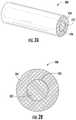
- FIGS. 2A-2Bare views of an example embodiment of a BIS optical fiber 200 (may also be referred to as a BIS fiber).
- the BIS optical fiber 200may be a single mode fiber or a multimode fiber.
- the BIS optical fiber 200may be a multimode fiber, a graded index optical fiber, a step index optical fiber, a single mode triangular index fiber, a step-index multimode fiber, or a graded-index multimode fiber.
- the BIS optical fiber 200is configured to function, when bent, as a step index multimode fiber and concurrently as a light scattering fiber.
- the BIS optical fiber 200is included in an endpoint traceable optical communication cable assembly, as described in more detail below with reference to FIGS. 9A-11 .
- the BIS optical fiber 200includes a core 202 (may also be referred to as a core layer, waveguide core, fiber core, etc.) with a first index of refraction.
- the core 202is surrounded by a cladding 204 (may also be referred to as a cladding layer, fiber cladding, etc.) with a second index of refraction that is lower than the first index of refraction of the core 202 .
- the cladding 204closely surrounds the core 202 to maintain light within the BIS optical fiber 200 by total internal reflection (e.g., when the BIS optical fiber 200 is substantially unbent) due to the difference in the index of refraction of the core 202 and the cladding 204 .
- an interface 206 between the core 202 and the cladding 204retains light within the core 202 due to total internal reflection at the interface 206 (e.g., when the BIS optical fiber 200 is substantially unbent).
- the core 202is devoid of nanovoids (e.g., airlines, dopants, germanium, laser ablations, etc.) or other similar nano-sized structures such that the BIS optical fiber 200 does not side scatter light when the BIS optical fiber 200 is in a substantially unbent or substantially straight orientation (may also be referred to as a zero-bend portion).
- the term “devoid of nanovoids” and similar language when used with reference to the core 202 of the BIS optical fiber 200means without structural gaps or defects greater than 5 nm in a cross-sectional diameter or length in the core 202 .
- void of nanovoidsincludes, for example, a fiber core 202 of the BIS optical fiber 200 that has no scattering centers of any size (e.g., in a silica core) or a cross-sectional area ratio in the core 202 of void to fiber of less than or equal to 0 to 1 ⁇ 10 ⁇ 5 .
- a BIS optical fiber 200 when bent above a bending radius of 10 mmhas a 10 dB extinction of 30 m or greater, and when bent below a bending radius of 10 mm has a side emission of 0.1 dB of the total launch power up to 30 dB.
- the terms “unbent”, “substantially unbent”, “straight”, and “substantially straight”, when used with reference to the BIS optical fiber 200means a curvature of about zero and/or a radius of curvature equal to or greater than the critical radius of curvature of the BIS optical fiber 200 .
- the terms “bent” or “bend” when used with reference to the BIS fibermeans a curvature of greater than zero and/or a radius of curvature less than the critical radius of curvature of the BIS optical fiber 200 .
- the BIS optical fiber 200is selectively movable from a light emitting position in which the radius of curvature of the bend is less than a critical radius of curvature and a light retaining position in which the radius of curvature of the bend is greater than a critical radius of curvature. Further, the BIS optical fiber 200 is selectively movable from the light emitting position to the light retaining position without damaging the core 202 or cladding 204 of the BIS optical fiber 200 .
- the core 202includes a pure silica and/or unused SMF (single-mode optical fiber) core cane.
- the core 202comprises undoped pure silica glass devoid of dopants, such as Ge (germanium), Al (aluminum), and/or P (phosphorous).
- the core 202has a diameter between about 80 ⁇ m (microns) and about 250 ⁇ m, in other embodiments the core 202 has a diameter between about 100 microns and about 125 microns, and in other embodiments the core 202 has a diameter of about 125 microns.
- Cores 202 that are significantly smaller than 125 microns in diametermay be subject to damage from handling and it may be more difficult to couple light into such small diameter cores 202 .
- Cores 202 that are significantly largere.g., larger than 250 microns in diameter
- the cladding 204has a diameter less than 250 microns (e.g., about 200 microns).
- the cladding 204is glass or a polymer having a diameter less than 250 microns (e.g., about 200 microns). This reduces the eccentricity (increases the concentricity) between the cladding diameter and the glass core diameter. With better concentricity, the fiber connectors may have better alignment between input fiber cores and output fiber cores. This leads to higher coupling efficiency and lower variability in coupling efficiency, which may increase the optical power visible (in traceable fiber applications) and/or reduce yield hit in manufacturing.
- the cladding 204comprises glass (e.g., fluorinated silica (Si0 2 ) glass) and/or a polymer (e.g., fluoro-acrylate).
- the cladding 204comprises one or more coatings, such as one or more fluorinated acrylate coatings (e.g., deposited during a fiber draw manufacturing step).
- the cladding 204comprises a diameter between about 100 ⁇ m and about 350 ⁇ m.
- the cladding 204comprises a first fluorinated acrylate cladding layer with a diameter between about 100 ⁇ m and about 350 ⁇ m, between about 110 ⁇ m and 155 ⁇ m, or at about 155 ⁇ m, and a second acrylate cladding layer with a diameter between about 140 to 250 ⁇ m, between about 180 to 240 ⁇ m, between about 190 to 200 ⁇ m, or at about 195 ⁇ m.
- the claddingcomprises a first fluorinated acrylate cladding layer with diameter between 100 to 170 ⁇ m and a second acrylate cladding layer with a diameter between 140 to 250 ⁇ m.
- the BIS optical fiber 200includes a scattering layer surrounding the cladding layer 204 .
- an ink layersurrounds the cladding layer 204 to promote light scattering from the cladding layer 204 .
- the scattering layerwhen used as a delivery fiber, is omitted (i.e., the BIS optical fiber 200 is devoid of the scattering layer).
- the claddingincludes a UV curable material and/or acrylate with a scattering material incorporated therein, such as, for example, an ink (e.g., titania) and/or a phosphor mixture.
- the cladding layer 204includes a first layer without a scattering material and a second, outer layer that includes a scattering material, such as a scattering ink.
- the cladding layer 204includes polymer OF-138, which may provide a number of advantages including robustness.
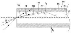
- FIG. 3Ais a schematic cross-sectional side view of the BIS optical fiber 200 of FIGS. 2A-2B in a substantially straight orientation (may also be referred to as a light retaining position) illustrating propagation of light paths (e.g., light paths 300 , 302 and 304 ) through the core 202 of the BIS optical fiber.
- lightis propagated through the BIS optical fiber 200 by total internal reflection when the BIS optical fiber 200 is unbent in a light retaining position due to the differing indices of refraction between the core 202 and the cladding layer 204 .
- the critical angle ⁇ cis the minimum or smallest angle of incidence at which light is reflected and smaller incidence angles will cause the light to be refracted (instead of reflected) and to exit the core 202 .
- a first light ray 302 traveling through the core 202reaches the interface 206 at a first angle ⁇ 1 , which is greater than the critical angle ⁇ c , and, as such, the first light ray 302 is reflected at the interface 206 , thereby propagating through the core 202 .
- a second light ray 304 traveling through the core 202reaches the interface 206 at a second angle ⁇ 2 , which is less than the critical angle ⁇ c , and, as such, the second light ray 304 is refracted (not reflected) at the interface 206 , thereby exiting the core 202 into the cladding 204 .
- FIG. 3Bis a schematic cross-sectional side view of the BIS optical fiber 200 of FIG. 2A-2B in a bent orientation (may also be referred to as a light emitting position) illustrating a second light ray 304 ′ exiting a core 202 of the BIS optical fiber 200 by macrobending to decrease the angle of incidence (e.g., ⁇ 2′′ ) of the second light ray 304 ′.
- the BIS optical fiber 200is configured such that when it is substantially straight or bent to a radius of curvature equal to or greater than a critical radius of curvature (e.g., in a light retaining position), the light propagates through the BIS optical fiber 200 .
- the first index of refraction of the core and the second index of refraction of the claddingare configured to maintain light within the core at the bend when the radius of curvature of the bend is greater than a critical radius of curvature.
- the BIS optical fiber 200is also configured such that when it is bent to a radius of curvature that is less than the critical radius of curvature (e.g., in a light emitting position), the light exits the core 202 at the cladding layer 204 at the bend.
- the BIS optical fiber 200is selectively movable from the light emitting position in which the radius of curvature is less than the critical radius of curvature and the light retaining position in which the radius of curvature is greater than the critical radius of curvature without damaging the core 202 or the cladding 204 of the BIS optical fiber 200 .
- the critical radius of curvatureis between about 1.5 mm and about 5 mm as measured from a center 305 ( 1 ) of the bend to an exterior surface 305 ( 2 ) of cladding layer 204 . Accordingly, bend radii smaller than the critical radius of curvature result in light emission from the core 202 of the BIS optical fiber 200 .
- the actual critical radius of curvaturemay be a critical bend range due to the highly multimoded nature of the core of the BIS fiber (e.g., a 125 ⁇ m core BIS fiber can support 600-700 modes at 532 nm compared with a single mode fiber that can carry one mode at 1550 nm wavelength).
- the critical radius of curvature R c for a BIS fiberis approximated by:
- R c3 ⁇ n 1 2 ⁇ ⁇ 4 ⁇ ⁇ ⁇ [ n 1 2 - n 2 2 ] 3 / 2 Equation ⁇ ⁇ 1
- R cis the critical radius of curvature
- mis the first index of refraction of the core of the BIS optical fiber 200
- n 2is the second index of refraction of the cladding of the BIS optical fiber 200 .
- the BIS optical fiber 200is a multimode fiber with a 125 ⁇ m HPFS (high purity fused silica) core with a first index of refraction (n 1 ) between 1.46 and 1.47 measured at 532 nm, a cladding with a diameter between about 155 ⁇ m and 160 ⁇ m and a second index of refraction (n 2 ) between 1.36 and 1.40 (e.g., 1.38) measured at 589 nm, and a critical radius between about 1.9 and 3 mm.
- HPFShigh purity fused silica
- the BIS optical fiber 200emits 0.21 dB of the launch power at a bend radius below 2.6 mm, and in particular emits 0.21 dB at a bend radius 2.6 mm, emits 0.25 dB at a bend radius 2.0 mm and emits 0.4 dB at a bend radius 1.0 mm.
- the multimode fiberincludes a 8-10 ⁇ m single mode core within the larger 125 ⁇ m multimode core.
- the single mode coreis used to measure the fiber for breaks (e.g., after extrusion into a fiber optic cable).
- dB losscan be determined by inserting a known launch power into a fiber, and then using sensors and meters to measure either the light scattered by side scalier measurements or the light transported through the fiber.
- Each modehas a critical radius of curvature at which light will begin to exit the core (couple to the cladding layer) and then scatter out from the BIS optical fiber.
- the effective refractive indexchanges according to Equation 1 above.
- n1 and n2 for the core 202 and cladding 204effectively change with bends in radius of curvature due to the changes in the angle of incidence of the internal reflection.
- the n2changes relative to n1 causing coupling of light from the core 202 to the cladding 204 and then scattering.
- coupling from the core mode to the cladding modeoccurs at different rates for each mode; however, in general tighter bends (with a smaller bend radius) increase mode coupling from the core to the cladding. In other words, bending decreases the difference in propagation constants from core to cladding modes.
- Each modewill have its own critical radius of curvature (Rc) because each mode will have its own coupling coefficient.
- Coupling coefficients for each mode ⁇are a product of the effective refractive index and the vacuum wavenumber. Scattering emission will change with bend diameter, where the critical radius of curvature will depend on the core diameter, the indices of refraction, and/or the mode launch light. In other words, the NA and the radius of curvature are related to emission.
- a first light ray 302 ′propagates through the BIS optical fiber 200 and intersects the interface 206 at a first substantially straight portion 306 of the BIS optical fiber 200 at a first angle of incidence ⁇ 1 ′ which is greater than the critical angle ⁇ c , passes through a bent portion 308 , and then intersects the interface 206 at a second substantially straight portion 310 at a second angle of incidence ⁇ 1 ′′ which is also greater than the critical angle ⁇ c .
- a second light ray 304 ′propagates through the BIS optical fiber 200 and intersects the interface 206 at the first substantially straight portion 306 at a first angle of incidence ⁇ 2 ′ which is greater than the critical angle ⁇ c , and then intersects the interface 206 at the bent portion 308 at a second angle of incidence ⁇ 2 ′′ which is less than the critical angle ⁇ c .
- the lightexits the core 202 at the bent portion 308 and enters the cladding 204 .
- the cladding 204i.e., cladding layer
- Light scattering mechanismsmay include a UV curable material and/or acrylate with ink (e.g., titania) and/or a phosphor mixture within the cladding layer 204 or on an external surface of the cladding layer 204 .
- the light scattering mechanismincludes an acrylate filled with a light scattering ink and applied outside of the cladding layer 204 , which may be made of a higher index protective acrylate.
- the cladding layer 204may include an internal scattering layer 312 at which light begins to scatter.
- the BIS optical fiber 200is configured to diffuse light by mechanical macrobending of the BIS optical fiber 200 (may also be referred to as macrobending emission, macrobending loss, tilt, etc.). Bending of the BIS optical fiber 200 is a reversible and repeatable action.
- the radius of curvaturedecreases below the critical radius of curvature, the light is scattered and as the radius of curvature increases (i.e., the BIS is straightened) above the critical radius of curvature R c , all or most of the light is bound in the non-scattering core 202 by total internal reflection.
- the radius of curvatureprovides a lever to turn on and off the emission (and side scattering) of light.
- the BIS optical fiber 200may also reduce cost in laser circuitry, laser cooling, and/or durability.
- the lasercan be kept on and allowed to reach a steady state with cooling, and the location at which the BIS optical fiber 200 emits light can be adjusted by macrobending only at the locations desired and, likewise, the timing of emission can be controlled by selective bending of the BIS optical fiber 200 .
- the BIS optical fiber 200diffuses light only at controlled locations and at controlled times (e.g., visible laser launch). As the core 202 of the BIS optical fiber 200 is devoid of nanovoids, the light is not scattered along the substantially straight portions 306 , 310 of the BIS optical fiber 200 , which increases the emission intensity at the bent portion 308 .
- the BIS optical fiber 200may be used as a data transmission fiber that is also a light diffusing fiber when the optical fiber extends beyond a particular radius of curvature to identify kinks or bends in the fiber. This enables slow to rapid illumination rates down a length of a fiber (e.g., which may be deployed on a length of a consumer product). For a given laser launch condition, there is an optical cladding index and radius of curvature that will allow for partial, scalable, repeatable, and reversible (e.g., does not damage the fiber) emission of visible radiation only at bend locations.
- the BIS optical fiber 200enables gradual illumination (may also be referred to as slow illumination) by mechanical means only, with no additional lights or electrical circuits.
- the BIS optical fiber 200can act as both a light scattering fiber and its own non-scattering delivery fiber at long distances without splices because, when bent, the BIS optical fiber 200 is both a step index multimode fiber and a light scattering fiber.
- the default function of the BIS optical fiber 200is a large area step index multimode fiber (may also be referred to as a light pipe), but when bent near or below its critical radius of curvature for the wavelength of light in use, the BIS optical fiber 200 becomes a light diffusing fiber emitting visible light (e.g., at several hundreds of microwatts of visible light) at the bend.
- the dual purpose of the BIS optical fiber 200enables remote location of a laser away from the desired lighting location without splicing of an additional delivery fiber.
- the BIS optical fiber 200is its own delivery fiber for as long as is necessary for the application (e.g., flashing light in a consumer lighting application). Excess BIS optical fiber 200 can also be deployed into a lighting system to enable long term re-commission and possibly later use of the BIS optical fiber 200
- a BIS optical fiber 200 held in tensionmay be pulled and released.
- a BIS optical fiber 200may be pulled, which causes the radius of curvature to decrease to near or below the critical radius of curvature, thereby causing light to leak out and then be scattered within the outer cladding 204 .
- the BIS optical fiber 200includes a core 202 including pure silica and being devoid of nanovoids, where the core 202 has a first index of refraction.
- the BIS optical fiber 200further includes a cladding 204 surrounding the core, where the cladding 204 has a second index of refraction lower than the first index of refraction of the core.
- the first index of refraction of the core and the second index of refraction of the claddingare configured to provide bend-only light emission from the core 202 to the cladding 204 when bent less than a critical radius of curvature.
- FIG. 4Ais a cross-sectional side view of the BIS optical fiber 200 of FIGS. 2A-3B positioned within a cable.
- FIG. 4Bis a cross-sectional side view of an alternative embodiment of the BIS optical fiber of FIGS. 2A-3B positioned within a jacket of a cable.
- a cable 400includes the BIS optical fiber 200 and one or more data transmission elements 402 A, 402 B (may also be referred to generally as data transmission elements 402 ).
- the BIS optical fiber 200may be configured to transmit data, and similarly, the data transmission elements 402 may also comprise BIS optical fibers 200 .
- the data transmission elements 402may be of the same type or different types as compared to one another.
- the data transmission element 402is a structure capable of carrying a data signal from one end of the cable 400 to the other.
- the data transmission element 402may be configured to transmit an electrical signal, for example, using a copper wire or other electrically conductive material.
- the data transmission element 402may be configured to transmit an optical signal by conducting electromagnetic waves such as ultraviolet, infrared, or visible light to carry data from one location to another.
- the data transmission elements 402may be an optical transmission element having a core 404 and a cladding 406 .
- the jacket 408 of the cable 400may be a hollow tube forming a conduit 410 that substantially surrounds the data transmission elements 402 and defines an outer surface 412 of the cable 400 .
- the data transmission elements 402may be partially or fully embedded within the jacket 408 .
- the jacket 408may be formed from an extruded polymer material, and/or may include multiple layers of materials where the outermost layer defines the outer surface 412 .
- the cable 400may include one or more strengthening members embedded within the material of the jacket 408 or located within the conduit 410 .
- the cable 400may include an elongate strengthening member (e.g., a fiber or rod) located within the conduit 410 and running the length of the jacket 408 , and that is formed from a material that is more rigid than the material of the jacket 408 .
- the strengthening membersmay be metal, braided steel, glass reinforced plastic, fiber glass, fiber glass yarns or other suitable material.
- the cable 400may include a variety of other elements embedded in or surrounded by the jacket 408 depending on the intended use of a particular cable 400 , including armor layers, moisture barrier layers, rip cords, etc. Additionally, the cable 400 may include other components such as steel armor and stranded and/or longitudinal strength elements. The cable 400 may be stranded, loose tube core cable construction, or other fiber optic cable construction.
- the cable 400also includes a BIS optical fiber 200 positioned within the conduit 410 of the jacket 408 .
- the BIS optical fiber 200is visible from an exterior of the cable 400 .
- At least a portion of the jacket 408is translucent or transparent to the tracer wavelength or wavelength range ⁇ T , or an optically visible shifted tracer wavelength or wavelength range ⁇ T *, along at least a portion of a length of the cable 400 .
- the BIS optical fiber 200may be incorporated as part of the cable 400 in one of several configurations.
- the BIS optical fiber 200may be adjacent to the data transmission elements 402 inside a conduit 410 defined by the jacket 408 .
- the BIS optical fiber 200may be mounted to the outer surface 412 of the jacket 408 or otherwise attached to the jacket 408 . In other embodiments, the BIS optical fiber 200 may be incorporated partially or fully within the jacket 408 , as shown in FIG. 4B .
- the cable jacket 408 ′ of the cable 400 ′includes a transparent portion 416 running at least a portion of the length of the cable 400 , with the BIS optical fiber 200 positioned within the transparent portion 416 .
- the BIS optical fiber 200acts as a tracing optical fiber.
- the BIS optical fiber 200enables an operator to identify kinks or bends in the cable 400 and/or identify one end of the cable 400 by injecting light into the opposite end of the cable 400 .
- the BIS optical fiber 200may conduct nonvisible light or visible light, such as green light (e.g., at approximately 520 nm), red light, blue light, or a combination thereof. Green light may be used due to the relative high degree of sensitivity of the human eye to green light and because 520 nm may be the lowest loss part of the transmission spectrum for the BIS optical fiber 200 .
- no lightis dispersed from the BIS optical fiber 200 .
- the BIS optical fiber 200At a radius of curvature of less than approximately 25 mm, the BIS optical fiber 200 generates dispersed visible light.
- cables 400are classified in terms of the relative bend sensitivities of the data transmission elements 402 (e.g., data transmission fiber) and the BIS optical fibers 200 .
- the critical radius of curvature for generating dispersed visible lightis greater than the critical radius of curvature for data transmission loss of the data transmission elements 402 above a particular percentage threshold (e.g., 1%, 5%, 10%, 20%, etc.).
- a particular percentage thresholde.g., 1%, 5%, 10%, 20%, etc.
- the data transmission elements 402e.g., optical data transmission fibers
- the BIS optical fiber 200can be engineered to disperse visible light at a bend sensitive radius of curvature R 2 that is slightly smaller than the data transmission radius of curvature R 1 .
- the bend sensitive radius of curvature R 2is within approximately 5 mm of the bend sensitive data transmission radius of curvature R 1 . In other embodiments, the bend sensitive radius of curvature R 2 is within approximately 2 mm of the bend sensitive data transmission radius of curvature R 1 . In yet other embodiments, the bend sensitive radius of curvature R 2 is within approximately 1 mm of the bend sensitive data transmission radius of curvature R 1 . Closer bend radii differences are also contemplated, as are larger bend radii differences. In this manner, there will be a bend-sensitive emission as the cable 400 approaches the bend sensitivity threshold of the data transmission element 402 (e.g., data transmission fiber).
- the data transmission element 402e.g., data transmission fiber
- the BIS optical fiber 200is selected such that (i) visible light at the tracer wavelength or wavelength range ⁇ T is dispersed from zero-bend portions of the BIS optical fiber 200 at a luminance that is less than 10 cd/m 2 and that (ii) visible light ⁇ T , ⁇ T * is dispersed from bent portions of the BIS optical fiber 200 , at bend radii of approximately 20 mm and below, at a luminance between approximately 80 cd/m 2 and approximately 200 cd/m 2 .
- the BIS optical fiber 200can be configured to disperse and scatter light at bend radii between about 2 mm and about 20 mm, i.e., scattering that is sufficient to permit visual identification of bends in the cable 400 at bend radii between about 2 mm and about 20 mm.
- FIG. 5Ais a chart 500 illustrating a typical index of refraction profile for the BIS fiber of FIGS. 2A-4B .
- the BIS optical fiberprovides a macro bending threshold below which more and more core modes couple to the cladding modes.
- FIG. 5Bis a chart 502 illustrating measured scattered light versus bending radius of curvature for the BIS fiber of FIGS. 2A-4B .
- FIG. 5Cis a chart 504 illustrating an effect of a relationship between bending radius of curvature and scattering power of the BIS optical fiber of FIGS. 2A-4B by increasing a numerical aperture of the BIS optical fiber.
- NA⁇ square root over (n core 2 ⁇ n clad 2 ) ⁇ Equation 2
- Nis the numerical aperture
- neonis the index of refraction of the core
- n cladis the index of refraction of the cladding.
- the fiber numerical aperture (NA)is between about 0.2 and about 0.5 (e.g., between 0.22 and 0.5), which corresponds to critical bending radii between about 40 mm and 1 mm respectively. In certain embodiments, the NA is about 0.41. In certain embodiments, particularly for BIS optical fibers 200 with a glass cladding 204 (see FIG. 2 ), the NA is between about 0.15 and 0.25 (e.g., about 0.2 cladding to core NA). In certain embodiments, particularly for BIS optical fibers 200 (see FIG. 2 ) with a polymer cladding 204 (see FIG.
- the NAis between about 0.30 and 0.45 (e.g., about 0.4 cladding to core NA) which allow for bends that, for example, fit into connectors and around lightbulb filaments, but still emit in the 0.2 to 0.5 lumens/mm range.
- the BIS optical fiber 200is configured to produce light emissions of 0.2 to 2 dB of the total internal light propagation with macro bend radii of 2 mm to 3.5 mm over 1 mm to 75 mm of fiber length.
- the light emitted from the core to the claddingis between about 0.2 dB and about 2 dB over 1 mm to 75 mm of fiber length at the bend when the radius of curvature of the bend is between about 2 mm to about 3.5 mm.
- Claddings with higher NAsmay require bends that damage the coatings and or glass, while claddings with lower NAs (e.g., below 0.2) may leak too much light to be used as a delivery fiber. It is noted that most light will leak out at the first bend even at a very large bend diameter. However, there are a large range of NAs bend diameters, launch conditions and core diameters that can be used to optimize scattering brightness at any location down the BIS optical fiber.
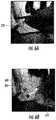
- FIG. 6Ais a perspective view of the BIS optical fiber 200 of FIGS. 2A-4B illustrating performance in a substantially straight orientation with 520 nm light.
- FIG. 6Bis a perspective view of the BIS optical fiber 200 of FIGS. 2 .A- 4 B illustrating performance in a bent orientation with 520 nm light, the bend portion 600 of the BIS optical fiber 200 coiled about 16 times around a rod with a 2.5 mm radius. It is noted that there is plenty of light for scattering again in the substantially straight portion 602 further down the BIS optical fiber 200 from the bend portion 600 .
- FIG. 7Ais a perspective view of the BIS optical fiber 200 of FIGS. 2A-4B illustrating performance in a substantially straight orientation with 520 nm light.
- FIG. 7Bis a perspective view of the BIS optical fiber 200 of FIGS. 2A-4B illustrating performance in a bent orientation with 520 nm light, the BIS optical fiber 200 coiled about 3 times around a rod with a 3 mm radius.
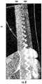
- FIG. 8is a perspective view of the BIS optical fiber 200 of FIGS. 2A-4B illustrating performance with 658 nm light before and within a 2.5 mm radius bending apparatus.
- the BIS optical fiber 200is pressed between teeth of gears 800 A, 800 B with controlled radii of curvature.
- FIGS. 9A-9Bare views of an exemplary cable tracing system 900 using the BIS optical fiber of FIGS. 2A-8 .
- a cable tracing system 900facilitates the identification (or “tracing”) of ends of a fiber optic cable 906 (e.g., traceable fiber optic cable) using fiber optic tracing signals.
- the cable tracing system 900comprises a traceable fiber optic cable assembly 902 (may also be referred to as an optical communication cable assembly) and a light launch device 904 .
- the cable tracing system 900allows a user to selectively attach the light launch device 904 to a part of the traceable fiber optic cable assembly 902 and use the light launch device 904 to inject one or more optical tracing signals (e.g., fiber optic tracing signal, a first optical tracing signal, second optical tracing signal, etc.) into the traceable fiber optic cable assembly 902 .
- optical tracing signalse.g., fiber optic tracing signal, a first optical tracing signal, second optical tracing signal, etc.
- the traceable fiber optic cable assembly 902comprises a fiber optic cable 906 , a first fiber optic connector 908 A (e.g., traceable fiber optic cable first connector, traceable fiber optic cable assembly first connector, etc.) at a first end of the fiber optic cable 906 , and a second fiber optic connector 908 B (e.g., traceable fiber optic cable second connector, traceable fiber optic cable assembly second connector, etc.) at a second end of the fiber optic cable 906 .
- the first fiber optic connector 908 A and the second fiber optic connector 908 Bare present on opposite ends (e.g., first end 909 A, and second end 909 B) of the fiber optic cable 906 to allow the traceable fiber optic cable assembly 902 to act as a patch cord between components of a network.
- the fiber optic cable 906may extend between two locations, such as two equipment racks in a data center, telecommunications room, or the like. Further, in some embodiments, the fiber optic cable 906 may have a length between about 0 meters and about 30 meters, and in some embodiments, the fiber optic cable 906 may have a length between about 1 meter and about 5 meters. In other embodiments, the fiber optic cable 906 may have a length of more than 30 meters.
- the first and second fiber optic connectors 908 A, 908 Bare merely an example.
- FIGS. 9A-9Billustrate the first and second fiber optic connectors 908 A, 908 B as an LC duplex connector
- the features described belowmay be applicable to different connector configurations and different connector sub-assembly designs. This may include simplex configurations of LC connector sub-assemblies, and both simplex and duplex configurations of different (i.e., non-LC) connector sub-assembly designs.
- the first fiber optic connector 908 A and the second fiber optic connector 908 Beach comprise a distal end 910 A and a proximal end 910 B. More specifically, the proximal end 910 B of the first fiber optic connector 908 A and the second fiber optic connector 908 B is towards a center of the fiber optic cable 906 , in other words, the distance between the proximal ends 910 B of the first and second fiber optic connectors 908 A, 908 B is less than the distance between the distal ends 910 A of the first and second fiber optic connectors 908 A, 908 B,
- the traceable fiber optic cable assembly 902comprises an end point only (EPO) configuration.
- EPOend point only
- a far end of the traceable fiber optic cable assembly 902e.g., second fiber optic connector 908 B
- illuminatese.g., lights up
- a near end of the traceable fiber optic cable assembly 902e.g., a first fiber optic connector 908 A
- receives an optical tracing signale.g., receives an optical tracing signal.
- the light launch device 904comprises a launch module 914 , a launch connector 916 , and a launch cable 918 therebetween.
- the launch module 914generates the fiber optic tracing signal for direction through the traceable fiber optic cable assembly 902 .
- the launch connector 916is selectively attachable to and removable from the first fiber optic connector 908 A and/or second fiber optic connector 908 B.
- the launch cable 918directs (e.g., propagates) the fiber optic tracing signal from the launch module 914 to the first fiber optic connector 908 A or the second fiber optic connector 908 B. In this way, one or more BIS optical fibers 200 (see FIGS.
- the launch connector 916comprises a distal end 920 A and a proximal end 920 B.
- the fiber optic cable 906is devoid of data transmission elements other than one or more BIS optical fibers 200 , which are configured to transmit data between the first and second fiber optic connectors 908 A, 908 B.
- FIG. 10is a view of the first fiber optic connector of FIGS. 9A-9B .
- the first and second fiber optic connectors 908 A, 908 B(e.g., optical connector, connector, etc.) are in the form of an LC duplex connector (although other types of connectors could be used).
- Each of the first and second fiber optic connector 908 A, 908 Bcomprises a housing 1000 , a connection interface 1002 , a locking member 1004 (e.g., lock feature), a boot 1006 , and a crimp band 1008 , as explained below in more detail. It is noted that any discussion of these components with respect to the one of the first and second fiber optic connectors 908 A, 908 B applies to both of the first and second optic connectors 908 A, 908 B.
- the connection interface 1002comprises first and second LC connector sub-assemblies 1010 A, 1010 B, As shown, each connector sub-assembly 1010 A, 1010 B includes a ferrule 1012 configured to support an optical fiber (e.g., the first and second data transmission fibers 1013 A, 1013 B) and a ferrule casing 1014 (e.g., connector sub-assembly housing, housing, etc.) surrounding a portion of the ferrule 1012 .
- the ferrule 1012extends from a ferrule holder that is retained in the ferrule casing 1014 by a cap 1018 or internal geometry of the ferrule casing 1014 .
- a springbiases the ferrule holder forward within the ferrule casing 1014 so that a front end of the ferrule 1012 projects beyond the ferrule casing 1014 .
- the front endpresents the optical fiber (e.g., data transmission fiber 1013 A, 1013 B) for optical coupling with a mating component (e.g., another fiber optic connector).
- Each connector sub-assembly 1010also includes a latch arm 1020 extending outwardly and rearwardly from a portion of the ferrule casing 1014 .
- the latch arm 1020has a proximal end coupled to the ferrule casing 1014 and a distal end spaced from the ferrule casing 1014 . The distal end of the latch arm 1020 may be depressed toward the ferrule casing 1014 for mating purposes.
- the housing 1000 of the first fiber optic connector 908 Aincludes a body 1022 in Which a rear portion of each connector sub-assembly 1010 (e.g., rear portions of ferrule casing 1014 ) is received.
- the body 1022comprises a top clamshell 1024 A and a bottom clamshell 1024 B (e.g., a two-piece construction).
- at least a portion of the first connectoris translucent and at least a portion of the second connector is translucent.
- at least a portion of the body 1022is translucent to allow at least a portion of the optical tracing signal to exit the housing 1000 .
- the entirety of the body 1022is translucent.
- translucentat least as used herein, comprises semi-transparent and transparent.
- semi-transparentidentifies objects that allow at least some light to pass through at least part of the object and transparent identifies objects that allow substantially all light to pass through all or part of the object.
- at least part of the body 1022is semi-transparent (e.g., translucent but not transparent).
- at least part of the body 1022is transparent.
- Top and bottom clamshells 1024 A, 1024 Battach together to define an interior 1026 (e.g., of the housing 1000 ).
- the first and second data transmission elements embodied as data transmission fibers 1013 A, 1013 Bare routed through the interior 1026 from the rear of the housing 1000 to the connector sub-assemblies 1010 .
- the top and bottom surface of the body 1022is mostly flat as this is where the light exits the body 1022 , and it is desirable to leave the light path uninterrupted until it reaches the locking member 1004 (described below in more detail).
- the housing 1000further comprises a trigger casing 1028 with a trigger arm 1030 extending forward and outwardly from a top of the trigger casing 1028 (and/or body 1022 ).
- the trigger arm 1030is depressible and biased upward (e.g., away from the body 1022 ).
- the trigger arm 1030extends outwardly from the body 1022 and over the distal end of the latch arm 1020 . This advantageously allows the trigger arm 1030 to engage and disengage both latch arms 1020 at the same time with a single trigger, and also inhibits fiber optic cables from snagging on the latch arms 1020 .
- the locking member 1004moves relative to the housing 1000 (including the trigger casing 1028 and trigger arm 1030 ) to allow or prevent the trigger arm 1030 from depressing and activating the latch arms 1020 .
- the trigger casing 1028is sliclably removable from the body 1022 , such as to reverse polarity of the first fiber optic connector 908 A (explained in more detail below).
- the trigger arm 1030is shown as a separate component (e.g., a clip) removably attached to the body 1022 , but may alternatively be integrally formed with the body 1022 so as to be part of a unitary (i.e., monolithic) structure with the body 1022 .
- providing the trigger arm 1030 as a removable componentmay provide certain benefits. For example, it may be possible to remove the trigger arm 1030 and attach it to the opposite side of the body 1022 .
- the connector sub-assemblies 1010may also be configured to independently rotate within the body 1022 so the latch arms 1020 can be orientated on the opposite side of the body 1022 as well.
- the fiber optic cable 906includes a jacket 408 (see FIGS. 4A-4B ).
- the housing 1000may be attached to a fiber optic cable 906 that includes the first and second data transmission fibers 1013 A, 1013 B (e.g., first and second optical data fibers and first and second BIS optical fibers 200 A, 200 B).
- the BIS optical fibers 200may be un-buffered fibers extending from within a jacket 408 of the fiber optic cable 906 .
- One or more strength memberse.g., aramid yarn
- the strength membersmay be secured to a rear 1007 of the housing 1000 by a crimp band 1008 that is crimped onto the rear of the housing 1000 .
- the fiber optic cable 906may have a different configuration or be secured to the housing 1000 or other part of the first fiber optic connector 908 A in a different manner (e.g., using an adhesive)
- the first fiber optic connector 908 Afurther includes a boot 1006 extending over a portion of the fiber optic cable 906 and the housing 1000 .
- the boot 1006comprises a substantially flat proximal surface 1032 (e.g., with a substantially rectangular cross section). Slots 1034 provide controlled bending for fiber optic cable 906 .
- Boot 1006is rotatably attached to the housing 1000 . More specifically, boot 1006 is able to be rotated at least about 45 degrees in both directions, thereby allowing removal of the trigger arm 1030 for polarity reversal (explained in more detail below).
- the housing 1000may further comprise a metal guide tube 1036 at a rear of the housing 1000 to further prevent sharp bends in the optical fibers as the optical fibers enter the body 1022 .
- the metal guide tube 1036comprises a cylindrical body 1038 with a first tapered end 1040 A and a second tapered end 1040 B opposite thereto. The first and second tapered ends 1040 A, 1040 B further prevent sharp bends.
- the metal guide tube 1036prevents the optical fibers from being pinched during assembly of the top clamshell 1024 A to the bottom clamshell 1024 B.
- FIG. 11is a top view of bottom clamshells 1024 B of the fiber optic connectors 908 A, 908 B of FIGS. 9A-10 of a fiber optic cable assembly with BIS optical fibers 200 A, 200 B as tracing fibers.
- top and bottom clamshells 1024 A, 1024 Bare identical, as discussed above, in other embodiments top and bottom clamshells 1024 A, 1024 B may not be substantially identical, such as one half may comprise all the alignment cavity features and the other half comprise all the alignment protrusion features. Likewise, other configurations are possible for securing the housing components together. Other variations include a housing formed from a single component that has an upper and lower portion connected by a living hinge.
- the BIS optical fibers 200 A, 200 Bextend between the first and second fiber optic connectors 908 A, 908 B of the of a fiber optic cable assembly 1100 .
- the fiber optic cable 906includes a first BIS optical fiber 200 A, and a second optical fiber 200 B positioned within the jacket 408 (data transmission fibers 1013 A, 1013 B (see FIG. 10 ) are omitted).
- the first bottom clamshell 1024 B( 1 ) (and/or first top clamshell 1024 A (see FIG. 10 ))includes a first entry channel 1101 A and a first emission channel 1102 A
- the second bottom clamshell 1024 B( 2 ) (and/or second top clamshell 1024 A (see FIG. 10 ))includes a second entry channel 1101 B and a second emission channel 1102 B (may be referred to generally as an entry channel 1101 and an emission channel 1102 ).
- a first end portion 1104 A (including a first end 1105 A) of a first BIS optical fiber 200 Ais positioned proximate (e.g., in or near) the first fiber optic connector 908 A.
- the first end portion 1104 A of the first BIS optical fiber 200 Ais positioned in the first entry channel 1101 A in the first fiber optic connector 908 A.
- a second end portion 1106 A (including a second end 1107 A) of the first BIS optical fiber 200 Ais positioned proximate (e.g., in or near) the second fiber optic connector 908 B.
- the first connectorincludes an entry channel 1101 A to maintain the first end portion 1104 A of the BIS optical fiber 200 A above the critical radius of curvature and the second connector 908 B includes an emission channel 1 . 102 E to maintain the second end portion 1106 B of the BIS optical fiber 200 A below the critical radius of curvature.
- the emission channel 1102 Bprovides about a 270 degree bend for the second end portion 1106 B of the BIS optical fiber 200 A.
- the second end portion 1106 B of the first BIS optical fiber 200 Ais positioned in the second emission channel 1102 B in the second fiber optic connector 908 B.
- a first end portion 1104 B (including a first end 1105 B) of the second BIS optical fiber 200 Bis positioned proximate (e.g., in or near) the second fiber optic connector 908 B.
- the first end portion 1104 Bis positioned in the second entry channel 1101 B in the second fiber optic connector 908 B.
- a second end portion 1106 B (including a second end 1107 B) of the second BIS optical fiber 200 Bis positioned proximate (e.g., in or near) the first fiber optic connector 908 A.
- the second end portion 1106 Bis positioned in the first emission channel 1102 A in the first fiber optic connector 908 A.
- the first bottom clamshell 1024 A( 1 )includes a first protrusion 1108 A positioned proximate the first entry channel 1101 A, between the first entry channel 1101 A and the rear 1007 ( 1 ) of the housing 1000 ( 1 ).
- the first protrusion 1108 Aprotrudes inwardly and has a radius of curvature above the critical radius of curvature.
- the first bottom clamshell 1024 ( 1 )includes a first central hub 1110 A defining a circular shape and having a radius of curvature below the critical radius of curvature.
- the second bottom clamshell 1024 A( 2 )includes a second protrusion 1108 B positioned proximate the second entry channel 1101 B, between the second entry channel 1101 B and the rear 1007 ( 2 ) of the housing 1000 ( 2 ).
- the second protrusion 1108 Bprotrudes inwardly and has a radius of curvature above the critical radius of curvature.
- the second bottom clamshell 1024 ( 2 )includes a second hub 1110 E defining a circular shape and having a radius of curvature below the critical radius of curvature.
- the entry channels 1101 and the protrusions 1108maintain a first radius of curvature of first and second entry bends 1112 A, 1112 B of first and second BIS optical fibers 200 A, 200 B above the critical radius of curvature for light entry into the BIS optical fibers 200 A, 200 B.
- the emission channels 1102 and central hubs 1110maintain a second radius of curvature of first and second emission bends 1110 A, 1110 B of the first and second BIS optical fibers 200 A, 200 B below the critical radius of curvature for light emission out of the BIS optical fibers 200 A, 200 B.
- the entry channels 1101 and protrusions 1108maintain (i.e., prevent from exceeding) the BIS optical fiber 200 above the critical radius of curvature for light emission thereby allowing entry of tracer light
- the emission channels 1102maintain (i.e., prevent from exceeding) the BIS optical fiber 200 below the critical radius of curvature for light emission (but above the radius of curvature for damaging the BIS optical fiber 200 ) thereby emitting tracer light within the fiber optic connectors 908 A, 908 B.
- At least part of the fiber optic connector 908 A, 908 Bis transparent, thereby allowing for end point only tracing applications, where light is emitted at the bends within the optical connectors, while also allowing for identification of bends and kinks in the cable.
- the first fiber optic connector 908 Aincludes a first entry channel 1101 A and a first protrusion 1108 A to maintain a first entry bend 1112 A of a first end portion 1104 A of the first BIS optical fiber 200 A above a critical radius of curvature for light emission, and the first fiber optic connector 908 A includes a first emission channel 1102 A and central hub 1110 A to maintain a second emission bend 1110 B of a second end portion 1104 B of the second optical fiber 200 B below a critical radius of curvature for light emission.
- the second connector 908 Bincludes a second entry channel 1101 B and second protrusion 1108 B to maintain a second entry bend 1108 B of a second end portion 1104 B of the second optical fiber 200 B above a critical radius of curvature for light emission, and the second connector 908 B includes a second emission channel 1102 B and a second central hub 1110 B to maintain a first emission bend 1110 A of a second end portion 1106 A of the first BIS optical fiber 200 A below a critical radius of curvature for light emission.
- the first and second entry channels 1101 A, 1101 B and first and second protrusions 1108 A, 1108 Bprovide a bend of about 90 degrees.
- the first and second emission channels 1102 A, 1102 B and first and second central hubs 1110 A, 1110 Bprovide a looped bend of about 270 degrees.
- the BIS optical fiber 200may be looped one or more times around the central hubs 1110 A, 1110 B.
- a first BIS optical fiber 200includes a first entry bend 1112 A in the first connector 908 A and a first emission bend 1114 A in the second connector 908 B, where the first emission bend 1114 A is less than the critical radius of curvature.
- the first entry bend 1112 Ais equal to or greater than about 90 degrees. In certain embodiments, the first entry bend 1112 A is equal to or greater than about 180 degrees. In certain embodiments, the first entry bend 1112 A is equal to or greater than about 270 degrees. In certain embodiments, the first emission bend 1114 A is equal to or greater than about 90 degrees. In certain embodiments, the first emission bend 1114 A is equal to or greater than about 180 degrees. In certain embodiments, the first emission bend 1114 A is equal to or greater than about 270 degrees. Other bends could be used for the entry channel 1101 and/or the emission channel 1102 .
- the BIS optical fiber 200serves as an End Point Only (EPO) traceable fiber, and can also identify bends and kinks in the cable, as discussed above.
- EPOEnd Point Only
- the BIS optical fiber 200By using a BIS optical fiber 200 instead of a non-scattering fiber, light at the far end of fiber optic connector 908 A, 908 B does not need to be redirected as it exits the side of the connector. Instead, the BIS optical fiber 200 will light up the connector uniformly, enhancing visibility. For example, a non-scattering fiber may lose light in a 90 degree bend and may not scatter evenly in all directions, which could substantially reduce the glow and visibility of the connector.
- the BIS optical fiber 200is configured to have a different lower NA from other fibers in the cable tracing system 900 to increase the amount of light emitted and scattered. In certain embodiments, there is an optimal fraction of light that should be scattered, as higher or lower scattering fractions may reduce the overall visibility of the far end fiber optic connector 908 A, 908 B.
- FIG. 12is a top view of bottom clamshells of the fiber optic connectors of FIGS. 9A-10 with a single BIS optical fibers as a tracing fiber.
- the fiber optic cable assembly 1200 of FIG. 12includes the same features as the fiber optic cable assembly 1100 of FIG. 11 , except where otherwise noted.
- a tracing optical fiber 1202is a BIS optical fiber, such that the first tracing optical fiber 1202 emits light at a first bend 1204 A within the first fiber optic connector 908 A, and the first tracing optical fiber 1202 emits light at a second bend 1204 B within the second fiber optic connector 908 B.
- the first tracing optical fiber 1202 , first bend 1204 A, and/or second bend 1204 Bare configured to emit light at an opposite end of a traceable fiber optic cable 1206 .
- first optical tracing signalis inserted into the first fiber optic connector 908 A, some light is emitted at the first bend 1204 A at the first fiber optic connector 908 A and then light is emitted again at the second bend 1204 B at the second fiber optic connector 908 B.
- first tracing optical fiber 1202 , first bend 1204 A, and/or second bend 1204 Bare specifically configured to emit some light for visual detection of a far end of the traceable fiber optic cable 1206 regardless of which end the light is injected, but is also configured not to emit too much light that too little light emits from the far end of the traceable fiber optic cable 1206 .
- the first bend 1204 A and the second bend 1204 Bare configured to emit 0.2 to 0.3 dB (e.g., with 30 mW being injected at the first fiber optic connector 908 A). This way, regardless of which end of the traceable fiber optic cable 1206 the first optical tracing signal is injected, a sufficient amount of light is emitted at the far end for easy and effective visual detection by a user.
- FIG. 13is a flowchart 1300 of steps for manufacturing the BIS optical fiber of FIGS. 2A-4B .
- a core 202(see FIGS. 2A-2B ) is formed, the core 202 including pure silica and being devoid of nanovoids, where the core 202 has a first index of refraction.
- a cladding 204(see FIGS. 2A-2B ) is formed and positioned around the core 202 , where the cladding 204 has a second index of refraction lower than the first index of refraction of the core 202 .
- the first index of refraction of the core 202 and the second index of refraction of the cladding 204are configured to maintain light within the core 202 when the BIS optical fiber 200 is unbent in a light retaining position and to emit light from the core 202 to the cladding 204 at a bend in the BIS optical fiber 200 when the radius of curvature of the bend is less than a critical radius of curvature and the BIS optical fiber 200 is in a light emitting position.
- the BIS optical fiber 200is selectively movable from the light emitting position in which the radius of curvature is less than the critical radius of curvature and the light retaining position in which the radius of curvature is greater than the critical radius of curvature without damaging the core 202 or the cladding 204 of the BIS optical fiber 200 .
- Optical data transmission fibers contemplated hereinmay comprise a single fiber, paired fibers, a plurality of optical fibers configured as an optical fiber ribbon, concentric bundles of optical fibers, or any other conventional or yet-to-be developed optical fiber configuration.
- the optical data transmission fibersmay comprise concentric bundles of optical fibers.
- optical tracer fibers disclosed hereinmay assume any location within an optical fiber cable assembly, regardless of where it lies in the cross section of the assembly.
- the cabling mediawhich may include strength members, buffer tubes, etc.
- optical fiber cabling mediamay take a variety of conventional and yet-to-be developed forms.
- an optical fiber cable assemblycomprises an optical waveguide disposed within a protective tube
- the optical waveguidemust be further protected within the tube and a certain amount of relative movement between the optical waveguide and the tube should be permitted.
- cabling mediaare referred to herein collectively as cabling media.
- un-armored and armored cable assembliesthat comprise concentric bundles of tight-buffered fibers within a polymer or flame retardant polymer jacket are contemplated by the present disclosure.
- Cable assemblies contemplated hereinmay further comprise a flexible, helically wrapped or corrugated, aluminum or steel interlocking armor surrounded by a polymer or flame-retardant polymer outer jacket.
- the concepts of the present disclosurewill enjoy applicability to a wide variety of optical fiber cable configurations and should not be limited to the particular embodiments disclosed herein.
Landscapes
- Physics & Mathematics (AREA)
- General Physics & Mathematics (AREA)
- Optics & Photonics (AREA)
- Optical Couplings Of Light Guides (AREA)
Abstract
Description
wherein Rcis the critical radius of curvature, m is the first index of refraction of the core of the BIS
NA=√{square root over (ncore2−nclad2)}
where NA is the numerical aperture, neon is the index of refraction of the core, and ncladis the index of refraction of the cladding. For a given radius of curvature, a larger NA will result in lower Rcand thus lower loss. While Rcis influenced by wavelength, for bends above Rcloss is not a strong function of wavelength within the visible light range.
Claims (22)
Priority Applications (2)
| Application Number | Priority Date | Filing Date | Title |
|---|---|---|---|
| US16/144,094US10539747B2 (en) | 2017-12-05 | 2018-09-27 | Bend induced light scattering fiber and cable assemblies and method of making |
| US16/151,884US10539758B2 (en) | 2017-12-05 | 2018-10-04 | Traceable fiber optic cable assembly with indication of polarity |
Applications Claiming Priority (2)
| Application Number | Priority Date | Filing Date | Title |
|---|---|---|---|
| US201762594798P | 2017-12-05 | 2017-12-05 | |
| US16/144,094US10539747B2 (en) | 2017-12-05 | 2018-09-27 | Bend induced light scattering fiber and cable assemblies and method of making |
Related Child Applications (1)
| Application Number | Title | Priority Date | Filing Date |
|---|---|---|---|
| US16/151,884ContinuationUS10539758B2 (en) | 2017-12-05 | 2018-10-04 | Traceable fiber optic cable assembly with indication of polarity |
Publications (2)
| Publication Number | Publication Date |
|---|---|
| US20190170949A1 US20190170949A1 (en) | 2019-06-06 |
| US10539747B2true US10539747B2 (en) | 2020-01-21 |
Family
ID=66659129
Family Applications (1)
| Application Number | Title | Priority Date | Filing Date |
|---|---|---|---|
| US16/144,094ActiveUS10539747B2 (en) | 2017-12-05 | 2018-09-27 | Bend induced light scattering fiber and cable assemblies and method of making |
Country Status (1)
| Country | Link |
|---|---|
| US (1) | US10539747B2 (en) |
Families Citing this family (10)
| Publication number | Priority date | Publication date | Assignee | Title |
|---|---|---|---|---|
| CN110249248B (en)* | 2017-01-30 | 2021-07-27 | 扇港元器件股份有限公司 | Optical connectors with reversible polarity |
| DE102017104628B4 (en)* | 2017-03-06 | 2023-06-22 | J-Fiber Gmbh | Light guide and method of detecting an excessively bent light guide |
| CN106918869B (en)* | 2017-04-17 | 2018-10-26 | 深圳市飞博康光通讯技术有限公司 | A kind of LC duplexs connector |
| US10539747B2 (en)* | 2017-12-05 | 2020-01-21 | Corning Research & Development Corporation | Bend induced light scattering fiber and cable assemblies and method of making |
| DE102018114420A1 (en)* | 2018-06-15 | 2019-12-19 | Osram Opto Semiconductors Gmbh | LIGHT FIBER AND LIGHTING DEVICE |
| US11943044B1 (en)* | 2019-03-21 | 2024-03-26 | Ast & Science, Llc | Continuous communication system using paired identical small satellites |
| CN113093345A (en)* | 2019-12-23 | 2021-07-09 | 深圳市雍邑科技有限公司 | Optical fiber jumper wire capable of being tracked and searched |
| US11698481B2 (en)* | 2020-10-26 | 2023-07-11 | Eminent Technologies Company, LLC | Traceable fiber using ferrule and cap at fan-out kit |
| US20230280541A1 (en)* | 2022-03-02 | 2023-09-07 | Corning Research & Development Corporation | Polarity changeable optical connector |
| CN119790338A (en)* | 2022-08-29 | 2025-04-08 | 康宁研究与开发公司 | Optical connector with rotatable protective cover and related methods |
Citations (266)
| Publication number | Priority date | Publication date | Assignee | Title |
|---|---|---|---|---|
| US3942859A (en) | 1974-11-11 | 1976-03-09 | Korodi Miklos B | Electrical conductor with light indicating means |
| JPS5711305A (en) | 1980-06-23 | 1982-01-21 | Fujikura Ltd | Optical fiber cable |
| US4412936A (en) | 1980-06-20 | 1983-11-01 | Khmelkov Stanislav F | Pigment for color-changing heat indicator |
| US4422719A (en)* | 1981-05-07 | 1983-12-27 | Space-Lyte International, Inc. | Optical distribution system including light guide |
| US4466697A (en)* | 1981-11-12 | 1984-08-21 | Maurice Daniel | Light dispersive optical lightpipes and method of making the same |
| JPS59182404A (en) | 1983-04-01 | 1984-10-17 | Showa Electric Wire & Cable Co Ltd | Radiation resistant optical fiber cable |
| JPS6017157U (en) | 1983-07-15 | 1985-02-05 | コクヨ株式会社 | Backrest lifting mechanism |
| US4557552A (en) | 1981-11-19 | 1985-12-10 | Board Of Trustees Of The Leland Stanford Junior University | Microbend optical fiber tapped delay line |
| JPS61139221A (en) | 1984-12-07 | 1986-06-26 | 住友電気工業株式会社 | How to determine the accident section of power lines |
| JPS61161827U (en) | 1985-03-27 | 1986-10-07 | ||
| US4637686A (en) | 1983-04-08 | 1987-01-20 | Kokusai Denshin Denwa Co., Ltd. | Optical fiber with light reflecting particles dispersed through buffer layers to dissipate leaky cladding modes |
| US4755018A (en) | 1986-01-23 | 1988-07-05 | Cgee Alsthom | Connector for optical fibers |
| US4762416A (en)* | 1985-11-08 | 1988-08-09 | Thomson-Csf | Monomode optical fiber reciprocal ring interferometer device |
| US4763984A (en) | 1987-01-02 | 1988-08-16 | Awai George K | Lighting apparatus and method |
| US4768854A (en)* | 1985-07-11 | 1988-09-06 | Raychem Corp. | Optical fiber distribution network including nondestructive taps and method using same |
| JPH0255506A (en) | 1988-08-20 | 1990-02-23 | Chubu Electric Power Co Inc | Overhead power line monitoring system |
| JPH02108007A (en) | 1988-10-17 | 1990-04-19 | Sumitomo Electric Ind Ltd | leaky fiber optic cable |
| JPH02108008A (en) | 1988-10-17 | 1990-04-19 | Sumitomo Electric Ind Ltd | leaky fiber optic cable |
| US4923274A (en) | 1989-06-26 | 1990-05-08 | Siecor Corporation | Connector for optical fibers |
| US4995691A (en) | 1989-10-16 | 1991-02-26 | Ensign-Bickford Optics Company | Angled optical fiber input end face and method for delivering energy |
| US5006806A (en) | 1989-03-15 | 1991-04-09 | Schonstedt Instrument Company | Methods and apparatus employing permanent magnets for marking, locating, tracing and identifying hidden objects such as burried fiber optic cables |
| US5017873A (en) | 1989-03-15 | 1991-05-21 | Schonstedt Instrument Company | Methods and apparatus employing permanent magnets for marking, locating, tracing and identifying hidden objects such as buried fiber optic cables |
| US5040867A (en) | 1990-03-21 | 1991-08-20 | Siecor Corporation | Slide fit optical connector having end cap to prevent rotation |
| US5122750A (en) | 1989-03-15 | 1992-06-16 | Schonstedt Instrument Company | Methods employing permanent magnets for marking, locating, tracing and identifying hidden objects such as buried fiber optic cables |
| US5179611A (en) | 1990-07-17 | 1993-01-12 | Tokai Rubber Industries, Ltd. | Optical fiber cable having a water absorptive member |
| GB2260198A (en) | 1991-05-16 | 1993-04-07 | John Michael Harrington | Coaxial cable tracer |
| US5206065A (en) | 1989-03-15 | 1993-04-27 | Schonstedt Instrument Company | Methods, apparatus and devices relating to magnetic markers for elongated hidden objects |
| US5305405A (en) | 1993-02-25 | 1994-04-19 | Adc Telecommunications, Inc. | Patch cord |
| JPH06130253A (en) | 1992-10-21 | 1994-05-13 | Fuji Electric Co Ltd | Fixing device for optical fiber connector |
| US5329348A (en) | 1991-10-04 | 1994-07-12 | The Furukawa Electric Co., Ltd. | Method of identifying a particular optical cable out of a number of similar optical cables |
| US5333228A (en) | 1993-05-21 | 1994-07-26 | Super Vision International Inc. | Lateral illumination fiber optic cable device and method of manufacture |
| US5377292A (en) | 1992-03-26 | 1994-12-27 | Kabel Rheydt A.G. | Optical fiber with additional color markings |
| US5394496A (en) | 1993-12-08 | 1995-02-28 | Northern Telecom Limited | Optical fiber mechanical splice |
| US5395362A (en) | 1992-01-14 | 1995-03-07 | Summit Technology | Methods and apparatus for distributing laser radiation |
| US5432876A (en) | 1992-10-19 | 1995-07-11 | Minnesota Mining And Manufacturing Company | Illumination devices and optical fibres for use therein |
| DE4413597A1 (en) | 1994-04-20 | 1995-10-26 | Tkm Telekommunikation Und Elek | Electric power or signals transmission line with marker light-guide |
| US5463706A (en) | 1994-02-16 | 1995-10-31 | Thomas & Betts Corporation | Light traceable transmission conduit assembly |
| US5500913A (en) | 1993-03-15 | 1996-03-19 | Administrators Of The Tulane Educational Fund | Apparatus and method of fabricating directional fiber optic taps, sensors and other devices with variable angle output |
| US5591160A (en) | 1993-09-24 | 1997-01-07 | Reynard; Michael | Fiber optic sleeve for surgical instruments |
| JPH09178956A (en) | 1996-10-24 | 1997-07-11 | Fujitsu Ltd | Connection cable detection method |
| JPH09237524A (en) | 1996-02-28 | 1997-09-09 | Kyowa Electron Instr Co Ltd | Lead cable with set position identification function |
| US5666453A (en) | 1994-07-15 | 1997-09-09 | Roy Witte | Fiber optic jumper cables and tracing method using same |
| US5741152A (en) | 1995-04-25 | 1998-04-21 | Amphenol Corporation | Electrical connector with indicator lights |
| US5764043A (en) | 1996-12-20 | 1998-06-09 | Siecor Corporation | Traceable patch cord and connector assembly and method for locating patch cord ends |
| WO1998034144A1 (en) | 1997-02-03 | 1998-08-06 | Integrated Optical Components Limited | Optical components |
| US5835654A (en) | 1995-12-08 | 1998-11-10 | Lucent Technologies Inc. | Optical coupling |
| WO1999024856A1 (en) | 1997-11-07 | 1999-05-20 | Gore Enterprise Holdings, Inc. | Optical subassembly for transmitting an optical signal with a controlled divergence angle and output power |
| US5937127A (en)* | 1996-05-17 | 1999-08-10 | Lumenyte International, Inc. | Linear light form with multilayered jacketing |
| US5979188A (en) | 1996-06-22 | 1999-11-09 | Northern Telecom Limited | Method of fabricating a planar waveguide structure |
| US5982967A (en) | 1997-12-12 | 1999-11-09 | Lucent Technologies Inc. | Color-coded optical fiber cable and a method for manufacturing the same |
| US6126325A (en) | 1998-01-21 | 2000-10-03 | Fujitsu Limited | Receptacle module for optical telecommunication |
| US6137935A (en) | 1997-04-24 | 2000-10-24 | Alcatel | Method for fabricating an optical cable |
| US6137928A (en) | 1999-01-29 | 2000-10-24 | Albrecht; Richard E. | Optical fiber light distribution system and method of manufacture and illumination |
| US6159037A (en) | 1998-11-05 | 2000-12-12 | 3Com Corporation | Illuminated connector |
| US6173097B1 (en) | 1998-07-01 | 2001-01-09 | Siecor Operations, Llc | Field installable multifiber connector |
| US6257750B1 (en) | 1999-07-09 | 2001-07-10 | Richard T. Strasser | Illuminating fire hose |
| US6278827B1 (en) | 1998-04-20 | 2001-08-21 | Bridgestone Corporation | Light transmission tubes |
| US6293081B1 (en) | 1997-06-12 | 2001-09-25 | Siecor Operations, Llc | Fiber optic cable marking process and a sensor device use therewith |
| US6301418B1 (en) | 1997-10-24 | 2001-10-09 | 3M Innovative Properties Company | Optical waveguide with diffuse light extraction |
| US6311000B1 (en) | 1996-02-13 | 2001-10-30 | Siemens Aktiengesellschaft | Optical cable and an apparatus for manufacturing the optical cable |
| US6317553B1 (en) | 1999-05-07 | 2001-11-13 | Lucent Technologies Inc. | Coated fiber strands having one or more heterogeneous regions and methods of making the same |
| US6314713B1 (en) | 1999-03-18 | 2001-11-13 | Pirelli Cables & Systems, Llc | Method and system for identifying a feature on a longitudinally advancing member and marking the advancing member based on the identification |
| US20010048797A1 (en) | 2000-03-14 | 2001-12-06 | Van Dijk Saskia I. | Fully indentifiable optical fiber assemblies |
| EP1168025A2 (en) | 2000-06-28 | 2002-01-02 | Nexans | Cable having side-emitting fiber under transparent or translucent cable jacket |
| US6356690B1 (en) | 1999-10-20 | 2002-03-12 | Corning Cable Systems Llc | Self-supporting fiber optic cable |
| US20020036775A1 (en) | 2000-08-08 | 2002-03-28 | Carl Zeiss Jena Gmbh | Method for increasing the spectral and spatial resolution of detectors |
| US20020037133A1 (en) | 2000-08-22 | 2002-03-28 | Unsworth John D. | Side firing optical fiber |
| US6388194B1 (en) | 1994-09-27 | 2002-05-14 | Hazardguard, Inc. | Electrical cable having indicating malfunction means therein |
| US6403947B1 (en) | 1999-03-18 | 2002-06-11 | Cambridge Research & Instrumentation Inc. | High-efficiency multiple probe imaging system |
| US6425694B1 (en) | 2000-09-18 | 2002-07-30 | Molex Incorporated | Fiber optic receptacle with protective shutter |
| US6439780B1 (en) | 2000-08-31 | 2002-08-27 | Corning Cable Systems Llc | Field-installable fiber optic ribbon connector and installation tool |
| US6456768B1 (en) | 2000-10-18 | 2002-09-24 | Fitel Usa Corp. | Optical fiber cable tracing system |
| US6456785B1 (en) | 1999-06-01 | 2002-09-24 | Robert Evans | Resistance heating element |
| US20020136497A1 (en) | 1999-10-05 | 2002-09-26 | Mcgarry Steven P. | Adaptive optical waveguides |
| US6471412B1 (en) | 2000-02-04 | 2002-10-29 | Molex Incorporated | Fiber optic connector receptacle |
| US20020159735A1 (en) | 2001-02-07 | 2002-10-31 | Bent Edvold | Dispersion compensating fiber with reduced splice loss and methods for making same |
| GB2375898A (en) | 2001-05-24 | 2002-11-27 | Christopher Kelly | Cable tracer for patch cords |
| US20020185299A1 (en) | 1999-03-10 | 2002-12-12 | Wolfgang Giebel | Underwater cable |
| US20030002830A1 (en) | 2001-06-27 | 2003-01-02 | Michael Petryszak | Method of determining lay length of S-Z stranded buffer tubes in optical fiber cable during manufacturing |
| US20030016924A1 (en) | 2001-07-10 | 2003-01-23 | Alcatel | Visibly distinguishable colored optical fiber ribbons |
| US6519396B2 (en) | 2000-06-09 | 2003-02-11 | Ccs Technology, Inc. | Aerial cable containing optical transmission elements and process for the manufacture of an aerial cable |
| US6526200B1 (en) | 1998-09-24 | 2003-02-25 | Ferranti Photonics Limited | Optical cable based directional way finding apparatus and method |
| US6532328B1 (en) | 2000-10-31 | 2003-03-11 | International Business Machines Corporation | Network cable with optical identification element |
| US6554485B1 (en) | 2000-09-11 | 2003-04-29 | Corning Cable Systems Llc | Translucent dust cap and associated method for testing the continuity of an optical fiber jumper |
| US6577243B1 (en) | 1999-12-14 | 2003-06-10 | Alan J. Brown | Method and apparatus for tracing remote ends of networking cables |
| US20030108270A1 (en) | 2001-12-05 | 2003-06-12 | Brimacombe Robert K. | Visible light tracer for high power-carrying optical fibers |
| US20030108303A1 (en)* | 2001-11-26 | 2003-06-12 | Autonetworks Technologies, Ltd. | Optical connector and structure of holding an optical fiber cord |
| US6596943B1 (en) | 1998-04-20 | 2003-07-22 | At&T Laboratories-Cambridge Ltd. | Cables |
| US20030152344A1 (en) | 2000-03-06 | 2003-08-14 | Patrice Brunet | Device for visual identification of cables or conduits |
| US6640028B1 (en)* | 2001-11-30 | 2003-10-28 | General Dynamics Advanced Technology Systems, Inc. | Bend-type fiber optic light injector |
| US6643443B2 (en) | 2000-09-21 | 2003-11-04 | Adc Telecommunications, Inc. | Cable storage cartridge |
| US20030206519A1 (en) | 2002-05-03 | 2003-11-06 | Michael Sanders | System and method for encoding and decoding messages |
| US20040022504A1 (en) | 2002-07-31 | 2004-02-05 | Hurley William C. | Transmit/receive optical cables |
| DE10239602B3 (en) | 2002-08-28 | 2004-02-19 | Krone Gmbh | Optical signal system, for a railway shunting yard, has a green-emitting laser coupled to an optic fiber along at least part of the length of connecting cable, giving externally visible illumination |
| US6695491B1 (en) | 1999-06-09 | 2004-02-24 | Tyco Electronics Raychem N.V. | Detent for optical fibres |
| US20040052473A1 (en) | 2002-09-03 | 2004-03-18 | The Furukawa Electric Co., Ltd. | Optical fiber connector part |
| US6710254B2 (en) | 2002-08-05 | 2004-03-23 | Test Rite International Company, Ltd. | Cable having location-indicating function |
| US20040101230A1 (en)* | 2002-11-26 | 2004-05-27 | Peter Philebrown | Optical arrangement with a low-radius fiber bend |
| US6758600B2 (en) | 2002-09-27 | 2004-07-06 | Corning Cable Systems Llc | Optical polarity modules and systems |
| US20040146254A1 (en) | 2002-07-16 | 2004-07-29 | Morrison John M. | Optical cable with indicator |
| US20040160774A1 (en) | 2003-02-13 | 2004-08-19 | Dell Products L.P. | Cable having an illuminating tracer element mounted thereon |
| US20040179777A1 (en) | 2003-03-10 | 2004-09-16 | Buelow Roger F. | Light pipe with side-light extraction |
| US20040196648A1 (en) | 2001-05-22 | 2004-10-07 | Franklin James Bruce | Side scattering polymer light guide and method of manufacture |
| US6816661B1 (en) | 2000-03-22 | 2004-11-09 | Corning Cable Systems Llc | Multifiber connector, installation tool and associated methods of validating optical fiber continuity |
| US6829651B1 (en) | 2000-04-11 | 2004-12-07 | International Business Machines Corporation | Local MAC address learning in layer 2 frame forwarding |
| US20050052174A1 (en) | 2003-09-05 | 2005-03-10 | Angelo Deborah A. | Traceable patch cable and connector assembly and method for identifying patch cable ends |
| US6876809B1 (en) | 2003-10-08 | 2005-04-05 | Nortel Networks Limited | Release mechanism for disconnecting internal fiber from an optical module |
| US20050089284A1 (en) | 2003-10-24 | 2005-04-28 | Ming-Chuan Ma | Light emitting cable wire |
| US6933438B1 (en) | 2002-10-04 | 2005-08-23 | The Lamson & Sessions Co. | Duct with wire locator |
| US20050212503A1 (en) | 2004-03-26 | 2005-09-29 | Deibele Craig E | Fast faraday cup with high bandwidth |
| WO2005106899A1 (en) | 2004-04-29 | 2005-11-10 | University Of Technology, Sydney | An optically traceable transmission cable for transmitting data or electricity and a traceable conduit |
| US6969273B2 (en) | 2004-03-26 | 2005-11-29 | Wilson Chen | Transmission cable for computer |
| US20050271338A1 (en) | 2004-06-04 | 2005-12-08 | Livingston Joseph C | Optical fiber array connectivity system utilizing angle polished ferrules and aligned-key adapters and cable for same |
| US6979223B2 (en) | 2004-03-26 | 2005-12-27 | Wilson Chen | Indicator circuit arrangement of a transmission cable for computer |
| US6995565B1 (en) | 1998-08-01 | 2006-02-07 | Airbus Uk Limited | Thermographic wiring inspection |
| US7020369B2 (en) | 2004-07-08 | 2006-03-28 | Berwick Offray Llc | Ribbon with fiber optics |
| WO2006044177A2 (en) | 2004-10-13 | 2006-04-27 | Nortel Networks Limited | Fiber tracer patch cord |
| US7038135B1 (en) | 2004-06-28 | 2006-05-02 | Avaya Technology Corp. | Embedded cable connection identification circuits |
| US20060104578A1 (en) | 2004-11-13 | 2006-05-18 | Alcoa Inc. | Fiber optic cable with miniature bend incorporated |
| US7049937B1 (en) | 2002-06-11 | 2006-05-23 | Nortel Networks Limited | Self-identifying cable for interconnecting electronic devices |
| US20060133750A1 (en) | 2004-12-20 | 2006-06-22 | Jean-Hway Lee | Light petal generation structure for optical fibers |
| US20060140562A1 (en)* | 2002-09-06 | 2006-06-29 | Joseph Edmond K | Side-scattering light guides |
| US7090411B2 (en) | 2002-02-22 | 2006-08-15 | Brown Joe D | Apparatus and method for diffusing laser energy that fails to couple into small core fibers, and for reducing coupling to the cladding of the fiber |
| US20060193575A1 (en) | 2005-02-28 | 2006-08-31 | Greenwood Jody L | Loose tube fiber optic cables having at least one access location |
| US7121707B2 (en) | 2002-02-14 | 2006-10-17 | Plastic Inventions And Patents, Inc. | Illuminated electrical cords and outlets |
| US20060232385A1 (en) | 2005-04-13 | 2006-10-19 | Scherer Christopher B | Networking cable tracer system |
| US7147383B2 (en) | 2004-12-22 | 2006-12-12 | Corning Cable Systems Llc | Optical polarity modules and systems |
| US20060285350A1 (en) | 2005-06-17 | 2006-12-21 | Bwt Property, Inc. | A Lighting System for Navigational Aids |
| US7164819B2 (en) | 2003-03-10 | 2007-01-16 | Fiberstars, Inc. | Side-light extraction by light pipe-surface alteration and light-extraction devices extending radially beyond the outer cladding |
| US7215860B2 (en)* | 2005-05-02 | 2007-05-08 | Lucent Technologies Inc. | Optical transmission fiber with a glass guiding cladding |
| WO2007053371A1 (en) | 2005-11-01 | 2007-05-10 | Corning Cable Systems Llc | Fiber optic cables suitable for automated preconnectorization |
| US7217152B1 (en) | 2005-12-19 | 2007-05-15 | Telect Inc. | Patch panel with tracer |
| US20070116402A1 (en) | 2005-06-30 | 2007-05-24 | Infoscitex Corporation | Humidity sensor and method for monitoring moisture in concrete |
| US20070153508A1 (en) | 2005-12-30 | 2007-07-05 | Jeffrey Nall | Lighting strips with improved manufacturability |
| US7242831B2 (en) | 2004-02-27 | 2007-07-10 | Verizon Business Global Llc | Low strain optical fiber cable |
| CN200941319Y (en) | 2006-08-28 | 2007-08-29 | 慧坦科技股份有限公司 | Wire able to change color when temp rising |
| US20070217749A1 (en) | 2006-03-14 | 2007-09-20 | Jong Michael D | Translucent dust cap for fiber optic adapter |
| US7313304B2 (en) | 2004-08-09 | 2007-12-25 | Sumitomo Electric Lightwave Corp. | Locatable dielectric optical fiber cable having easily removable locating element |
| US7330632B1 (en)* | 2006-08-23 | 2008-02-12 | Energy Focus, Inc. | Fiberoptic luminaire with scattering and specular side-light extractor patterns |
| US20080087082A1 (en) | 2004-08-06 | 2008-04-17 | Hankuk Sensys Co., Ltd. | Method and Device for Measuring Acceleration and/or Inclination by Using Thermal Convention of a Fluid |
| WO2008048955A2 (en) | 2006-10-16 | 2008-04-24 | Panduit Corp. | Patch cord with a light pipe |
| US20080121171A1 (en) | 2006-11-28 | 2008-05-29 | Hulsey James | Temperature sensitive color changing cable apparatus |
| JP2008153030A (en) | 2006-12-15 | 2008-07-03 | Toko Electrical Construction Co Ltd | Cable with identification function |
| US7401961B2 (en) | 2002-05-02 | 2008-07-22 | Fatzer Ag | Luminous wire rope |
| US7406231B1 (en) | 2005-06-21 | 2008-07-29 | Avaya Technology Corp. | Electroluminescent patch cable |
| US20080198618A1 (en) | 2007-02-16 | 2008-08-21 | Todd Michael North | Networking cable with lighting system for cable tracing |
| US20080204235A1 (en) | 2007-02-22 | 2008-08-28 | Superior Essex Communications Lp | Fiber optic cable with integral radio frequency identification system |
| US20080219621A1 (en)* | 2004-12-06 | 2008-09-11 | Pirelli & C. S.P.A. | Point-To-Point Optical Fibre Link |
| US20080273844A1 (en) | 2007-05-04 | 2008-11-06 | Dr. Anthony Stephen Kewitsch | Electrically Traceable and Identifiable Fiber Optic Cables and Connectors |
| DE102007025494A1 (en) | 2007-06-01 | 2008-12-04 | Schilli, Bernd, Dipl.-Ing. (FH) | Powerful electric cable tracer for locating tracing cables and pipes, and depth measurements, has simple converter or transformer based on low voltage halogen illumination technique |
| KR100875507B1 (en) | 2008-06-24 | 2008-12-22 | 이병렬 | Temperature-sensitive discoloration numbering tube |
| US20090027873A1 (en) | 2007-07-06 | 2009-01-29 | Tarlton Peter B | Illumination source |
| US7544909B2 (en) | 2006-10-25 | 2009-06-09 | Dhir Alok K | Illuminated cable |
| US7596293B2 (en) | 2006-04-18 | 2009-09-29 | Corning Cable Systems Llc | Loopback device utilizing bend insensitive optical fiber |
| US7603020B1 (en) | 2008-05-27 | 2009-10-13 | Emerson Network Power, Energy Systems, North America, Inc. | Cable clamp with integrated trace and bond capability |
| JP2009244288A (en) | 2008-03-28 | 2009-10-22 | Toyokuni Electric Cable Co Ltd | Optical fiber cable with connector |
| EP2113969A1 (en) | 2008-04-30 | 2009-11-04 | Tyco Electronics Corporation | Connector assembly having a light pipe assembly |
| US7618175B1 (en) | 2005-07-08 | 2009-11-17 | Ilight Technologies, Inc. | LED lighting system with helical fiber filament |
| US7620279B2 (en) | 2004-12-17 | 2009-11-17 | Poly Optics Australia Pty. Ltd. | Polyurethane light guides |
| US20090297104A1 (en) | 2008-05-28 | 2009-12-03 | Kachmar Wayne M | Fiber optic cable |
| US20090299440A9 (en) | 2001-12-10 | 2009-12-03 | Michael Slatkine | Method and apparatus for improving safety during exposure to a monochromatic light source |
| WO2010011299A2 (en) | 2008-07-25 | 2010-01-28 | Corning Incorporated | Nanostructured optical fiber illumination systems and methods for biological applications |
| US20100021114A1 (en) | 2008-07-24 | 2010-01-28 | Xin Chen | Double-Clad Optical Fibers And Devices With Double-Clad Optical Fibers |
| WO2010021896A1 (en) | 2008-08-22 | 2010-02-25 | 3M Innovative Properties Company | Light guides including laser-processed light extractors and methods |
| US7671279B2 (en) | 2005-11-10 | 2010-03-02 | Yongjiang Yin | Current-seen cable |
| CN201419706Y (en) | 2009-05-18 | 2010-03-10 | 唐山轨道客车有限责任公司 | A high-speed EMU skirt plate locking structure |
| US20100066254A1 (en) | 2006-12-22 | 2010-03-18 | Hubert Ott | Light-Emitting Device |
| US20100148747A1 (en) | 2008-12-15 | 2010-06-17 | Rathbun Dale Ii | Traceable fiber optic jumpers |
| US20100166374A1 (en) | 2007-04-10 | 2010-07-01 | Lapp Engineering & Co. | Cable |
| US7748860B2 (en) | 2006-11-24 | 2010-07-06 | Patrice Brunet | Identification device for visually identifying cables or ducts over their entire length |
| DE102009015263A1 (en) | 2009-04-01 | 2010-10-14 | Areva Np Gmbh | electric wire |
| US7817884B2 (en) | 2007-10-30 | 2010-10-19 | Corning Incorporated | Strain-managed optical waveguide assemblies and methods of forming same |
| JP2010237233A (en) | 2009-03-30 | 2010-10-21 | Fujikura Ltd | Optical fiber with connector |
| US20100274235A1 (en) | 2007-12-06 | 2010-10-28 | Koninklijke Philips Electronics N.V. | Apparatus, method and computer program for applying energy to an object |
| US20100329604A1 (en)* | 2009-06-30 | 2010-12-30 | Hitachi Cable, Ltd. | Optical connector |
| US20110034068A1 (en) | 2009-08-05 | 2011-02-10 | Realm Communications Group, Inc. | Networking cable with tracer optical waveguide |
| US20110085776A1 (en) | 2008-09-02 | 2011-04-14 | Eric Biribuze | High-Density Patch-Panel Assemblies for Optical Fiber Telecommunications |
| US7932805B2 (en) | 2003-07-08 | 2011-04-26 | Cooper Technologies Company | Fuse with fuse state indicator |
| US20110103747A1 (en) | 2009-10-30 | 2011-05-05 | Hon Hai Precision Industry Co., Ltd. | Optical fiber connector configured with separated seat member and lens member |
| US20110103757A1 (en) | 2008-02-14 | 2011-05-05 | Jochen Alkemper | Side-emitting step index fiber |
| US20110122646A1 (en) | 2009-11-20 | 2011-05-26 | Scott Robertson Bickham | Optical Fiber Illumination Systems and Methods |
| US8102169B2 (en) | 2008-07-25 | 2012-01-24 | International Business Machines Corporation | Cable tracing system and method for cable management |
| US20120019900A1 (en) | 2009-07-07 | 2012-01-26 | Stephen Kitson | Light diffusers and displays comprising same |
| US8152385B2 (en) | 2009-02-27 | 2012-04-10 | Corning Cable Systems Llc | Duplex fiber optic assemblies suitable for polarity reversal and methods therefor |
| US8167471B1 (en) | 2009-11-19 | 2012-05-01 | Daniel Moritz | Self-illuminating extension cord |
| CN202305952U (en) | 2011-11-08 | 2012-07-04 | 李即佳 | able with high sensitivity |
| CN102589728A (en) | 2012-03-07 | 2012-07-18 | 大同电线电缆科技(吴江)有限公司 | Temperature-sensing color-changing cable |
| US20120275180A1 (en) | 2011-04-29 | 2012-11-01 | Leslie James Button | Light Diffusing Fibers and Methods for Making the Same |
| US20120275178A1 (en)* | 2011-04-26 | 2012-11-01 | Stephan Lvovich Logunov | Light-coupling optical systems and methods employing light-diffusing optical fibert |
| US20120275745A1 (en) | 2011-04-26 | 2012-11-01 | Stephan Lvovich Logunov | Systems and Methods for Coupling Light into a Transparent Sheet |
| US8322871B1 (en) | 2010-05-26 | 2012-12-04 | Telect, Inc. | Optical fiber tracing system |
| US20120308183A1 (en) | 2011-06-06 | 2012-12-06 | Panduit Corp. | Duplex Clip Assembly for Fiber Optic Connectors |
| US8351750B2 (en)* | 2002-12-09 | 2013-01-08 | Noam Meir | Flexible optical device |
| US20130021597A1 (en) | 2011-07-21 | 2013-01-24 | International Business Machines Corporation | Cable identification |
| US8408029B2 (en) | 2009-11-17 | 2013-04-02 | Corning Incorporated | Method for thermally conditioning molten glass |
| US8414319B2 (en) | 2008-11-12 | 2013-04-09 | Panduit Corp. | Patch cord with insertion detection and light illumination capabilities |
| US20130088888A1 (en) | 2011-10-07 | 2013-04-11 | Edward John Fewkes | Optical Fiber Illumination Systems and Methods |
| WO2013055842A1 (en) | 2011-10-11 | 2013-04-18 | Corning Incorporated | Multi-wavelength light source using light diffusing fibers |
| WO2013059811A1 (en) | 2011-10-21 | 2013-04-25 | Energy Focus, Inc. | Efficient side-light distribution system |
| US20130107565A1 (en) | 2011-10-31 | 2013-05-02 | Michael Lucien Genier | Light diffusing optical fiber with uv protection layer |
| US8492448B2 (en) | 2011-10-07 | 2013-07-23 | Corning Incorporated | Systems and methods for performing photoreactions using light-diffusing optical fiber |
| US20130201001A1 (en) | 2012-02-07 | 2013-08-08 | Nitesh Ratnakar | End connection identification device and method |
| US8509579B2 (en) | 2009-03-16 | 2013-08-13 | Fernando Ramon Martin-Lopez | Solar energy collector |
| US20130209037A1 (en)* | 2012-02-09 | 2013-08-15 | Terry L. Cooke | Cable leg and connector management system |
| US20130209045A1 (en) | 2012-02-13 | 2013-08-15 | David L. Dean, Jr. | Visual tracer system for fiber optic cable |
| JP2013196960A (en) | 2012-03-21 | 2013-09-30 | Nec Computertechno Ltd | Cable and cable discrimination method |
| CN203241575U (en) | 2013-05-09 | 2013-10-16 | 东莞市多亚电子有限公司 | A SFP fiber optic socket |
| US8582939B2 (en) | 2010-11-23 | 2013-11-12 | Corning Cable Systems Llc | Fiber optic cables with access features |
| US8582940B2 (en) | 2010-10-28 | 2013-11-12 | Corning Cable Systems Llc | Fiber optic cables with extruded access features and methods of making fiber optic cables |
| US20130341922A1 (en) | 2012-05-03 | 2013-12-26 | Gamesa Innovation & Technology, S.L. | Method and module for measuring the rate of change of frequency of waveforms related to converter units in wind turbine generators |
| WO2014026300A1 (en) | 2012-08-17 | 2014-02-20 | Lopez Domez Mariano | Energy extraction system for illuminating cables, among other uses, which comprises a power cable and an energy extraction device; method for manufacturing and repairing said system |
| US8662760B2 (en) | 2010-10-29 | 2014-03-04 | Corning Cable Systems Llc | Fiber optic connector employing optical fiber guide member |
| US20140070639A1 (en) | 2012-09-07 | 2014-03-13 | Denso Corporation | Rotary electric machine |
| US8724842B2 (en) | 2012-03-21 | 2014-05-13 | Sound Sources Technology, Inc. | Universal angle loudspeaker bracket |
| US8770525B2 (en) | 2009-07-21 | 2014-07-08 | Afl Telecommunications Llc | High density cable management bracket |
| US8791829B2 (en) | 2005-03-07 | 2014-07-29 | The Interactive Institute Ii Ab | Visualisation arrangement |
| US8798419B2 (en) | 2010-08-23 | 2014-08-05 | Commscope, Inc. Of North Carolina | Conductive elements in cable jackets and separators |
| US20140221763A1 (en) | 2012-09-24 | 2014-08-07 | Invuity, Inc. | Methods and apparatus for controlling optical properties of light |
| US20140270639A1 (en) | 2013-03-12 | 2014-09-18 | Schott Corporation | Optical element for mie scattering light from an optical fiber |
| US8896287B2 (en) | 2011-11-30 | 2014-11-25 | International Business Machines Corporation | Cable identification using a unique signal carried on an external conductor |
| US8896286B2 (en) | 2011-11-30 | 2014-11-25 | International Business Machines Corporation | Cable identification using a unique signal carried on an unused conductor |
| US20140355295A1 (en) | 2013-05-31 | 2014-12-04 | Corning Incorporated | Uniform illumination light diffusing fiber device |
| US8909013B1 (en) | 2013-06-14 | 2014-12-09 | Amphenol Fiber Optic Technology (Shenzhen) | Traceable cable assembly |
| US20140363134A1 (en) | 2013-06-10 | 2014-12-11 | Corning Optical Communications LLC | Optical fiber cable assembly comprising optical tracer fiber |
| US8929703B2 (en) | 2011-12-19 | 2015-01-06 | Corning Incorporated | Uniform UV efficient light diffusing fiber |
| WO2015000194A1 (en) | 2013-07-01 | 2015-01-08 | 深圳市特发信息光网科技股份有限公司 | Passive visible light patch cord tracers, light patch cord and method for tracking light patch cord |
| US20150043875A1 (en) | 2013-08-12 | 2015-02-12 | Corning Optical Communications LLC | Optical fiber cable assembly comprising optical tracer fiber |
| US20150049992A1 (en) | 2013-08-13 | 2015-02-19 | Corning Cable Systems Llc | Optical fiber cable with cable heating element |
| US9025923B2 (en) | 2011-12-19 | 2015-05-05 | Corning Incorporated | Uniform white color light diffusing fiber |
| US9073243B2 (en) | 2010-04-30 | 2015-07-07 | Corning Cable Systems Llc | Fiber optic cables with access features and methods of making fiber optic cables |
| US20150277059A1 (en) | 2012-10-10 | 2015-10-01 | Fibrefab Limited | Fibre optic connector device |
| DE202015007044U1 (en) | 2015-10-08 | 2015-11-12 | Rosenberger-Osi Gmbh & Co. Ohg | Patch cord and identification device with such a jumper cable |
| US9196975B2 (en) | 2010-04-29 | 2015-11-24 | Mertek Industries, Llc | Networking cable tracer system |
| US9271709B2 (en) | 2006-01-18 | 2016-03-01 | Invuity, Inc. | Retractor illumination system |
| US9304278B1 (en) | 2015-03-31 | 2016-04-05 | Corning Optical Communications LLC | Traceable cable with side-emitting optical fiber and method of forming the same |
| US20160116660A1 (en)* | 2014-10-22 | 2016-04-28 | Corning Incorporated | Double clad light diffusing fiber, connector system and illuminaire |
| US20160139353A1 (en) | 2014-11-18 | 2016-05-19 | Corning Optical Communications LLC | Traceable optical fiber cable and filtered viewing device for enhanced traceability |
| US9388975B2 (en) | 2013-11-07 | 2016-07-12 | Swisscom Ag | Communication cables with illumination |
| US20160202418A1 (en) | 2013-06-14 | 2016-07-14 | Exfo Inc. | Optical fiber modal distribution conditioner |
| US20160231521A1 (en) | 2013-09-16 | 2016-08-11 | 3M Innovative Properties Company | Optical communication assemblies |
| US9435713B2 (en) | 2012-05-29 | 2016-09-06 | Afl Telecommunications Llc | System and method for identifying fiber sequence in a multi-fiber optical cable |
| US9448380B2 (en) | 2010-09-16 | 2016-09-20 | Gm Plast A/S | Optical fibre guiding |
| US20160291277A1 (en) | 2015-03-31 | 2016-10-06 | Corning Optical Communications LLC | Traceable cable with side-emitting optical fiber and method of forming the same |
| WO2016170172A1 (en) | 2015-04-22 | 2016-10-27 | CommScope Connectivity Belgium BVBA | Deploying optical fibers within a multi-dwelling unit |
| US20160313513A1 (en) | 2013-12-09 | 2016-10-27 | Koninklijke Philips N.V. | Optical fiber connector validation |
| US20160313483A1 (en) | 2015-04-24 | 2016-10-27 | Bogdan Chomycz | Cable Identifier |
| US20160341922A1 (en) | 2015-05-20 | 2016-11-24 | Corning Optical Communications LLC | Traceable cable with side-emitting optical fiber and method of forming the same |
| US9507096B2 (en) | 2012-07-26 | 2016-11-29 | Corning Optical Communications LLC | Fiber optic connectors employing moveable optical interfaces with fiber protection features and related components and methods |
| US9529167B2 (en) | 2014-05-30 | 2016-12-27 | Liseen Corporation | Optical cable module and method for manufacturing the same |
| US20160377818A1 (en) | 2014-01-14 | 2016-12-29 | Tyco Electronics (Shanghai) Co., Ltd. | Alignment system and method for calibrating position of optical fiber bore ferrule |
| US9571694B2 (en) | 2014-06-06 | 2017-02-14 | Canon Kabushiki Kaisha | Image reading apparatus, method for controlling the same, and storage medium |
| US20170123167A1 (en) | 2015-10-30 | 2017-05-04 | Corning Optical Communications LLC | Traceable cable assembly and connector |
| US20170176691A1 (en) | 2015-12-19 | 2017-06-22 | US Conec, Ltd | Field Changeable Fiber Optic Connector Polarity Keying with Color Coding |
| US9709750B1 (en) | 2016-06-21 | 2017-07-18 | Alliance Fiber Optic Products Inc. | 2-dimensional fiber array structure |
| US20170207585A1 (en) | 2016-01-19 | 2017-07-20 | Corning Optical Communications LLC | Traceable cable system, traceable cable assembly and connector |
| US20170205587A1 (en) | 2016-01-15 | 2017-07-20 | Senko Advanced Components, Inc. | Fiber optic connector assemblies with adjustable polarity |
| US20170293102A1 (en)* | 2016-04-08 | 2017-10-12 | Corning Optical Communications LLC | Traceable end point cable assembly |
| US20170315318A1 (en) | 2016-04-29 | 2017-11-02 | Corning Optical Communications LLC | Preferential mode coupling for enhanced traceable patch cord performance |
| US20180128996A1 (en) | 2016-11-07 | 2018-05-10 | 3M Innovative Properties Company | Optical fiber connector with integrated installation tools |
| US20180136398A1 (en) | 2015-07-17 | 2018-05-17 | Corning Optical Communications LLC | Systems and methods for traceable cables |
| US20180136399A1 (en) | 2015-07-17 | 2018-05-17 | Corning Optical Communications LLC | Systems and methods for tracing cables and cables for such systems and methods |
| US20180172925A1 (en)* | 2016-12-21 | 2018-06-21 | Corning Optical Communications LLC | Traceable end point cable assembly having a tracing waveguide |
| US10120138B2 (en)* | 2016-06-13 | 2018-11-06 | Corning Research & Development Corporation | Connector with trigger locking feature, and cable assemblies and methods including the same |
| US20190064447A1 (en) | 2017-08-24 | 2019-02-28 | Senko Advanced Components, Inc. | Ultra-small form factor optical connectors using a push-pull boot receptacle release |
| US10234614B2 (en)* | 2017-01-20 | 2019-03-19 | Corning Research & Development Corporation | Light source assemblies and systems and methods with mode homogenization |
| US20190170949A1 (en)* | 2017-12-05 | 2019-06-06 | Corning Research & Development Corporation | Bend induced light scattering fiber and cable assemblies and method of making |
- 2018
- 2018-09-27USUS16/144,094patent/US10539747B2/enactiveActive
Patent Citations (320)
| Publication number | Priority date | Publication date | Assignee | Title |
|---|---|---|---|---|
| US3942859A (en) | 1974-11-11 | 1976-03-09 | Korodi Miklos B | Electrical conductor with light indicating means |
| US4412936A (en) | 1980-06-20 | 1983-11-01 | Khmelkov Stanislav F | Pigment for color-changing heat indicator |
| JPS5711305A (en) | 1980-06-23 | 1982-01-21 | Fujikura Ltd | Optical fiber cable |
| US4422719A (en)* | 1981-05-07 | 1983-12-27 | Space-Lyte International, Inc. | Optical distribution system including light guide |
| US4466697A (en)* | 1981-11-12 | 1984-08-21 | Maurice Daniel | Light dispersive optical lightpipes and method of making the same |
| US4557552A (en) | 1981-11-19 | 1985-12-10 | Board Of Trustees Of The Leland Stanford Junior University | Microbend optical fiber tapped delay line |
| JPS59182404A (en) | 1983-04-01 | 1984-10-17 | Showa Electric Wire & Cable Co Ltd | Radiation resistant optical fiber cable |
| US4637686A (en) | 1983-04-08 | 1987-01-20 | Kokusai Denshin Denwa Co., Ltd. | Optical fiber with light reflecting particles dispersed through buffer layers to dissipate leaky cladding modes |
| JPS6017157U (en) | 1983-07-15 | 1985-02-05 | コクヨ株式会社 | Backrest lifting mechanism |
| JPS61139221A (en) | 1984-12-07 | 1986-06-26 | 住友電気工業株式会社 | How to determine the accident section of power lines |
| JPS61161827U (en) | 1985-03-27 | 1986-10-07 | ||
| US4768854A (en)* | 1985-07-11 | 1988-09-06 | Raychem Corp. | Optical fiber distribution network including nondestructive taps and method using same |
| US4762416A (en)* | 1985-11-08 | 1988-08-09 | Thomson-Csf | Monomode optical fiber reciprocal ring interferometer device |
| US4755018A (en) | 1986-01-23 | 1988-07-05 | Cgee Alsthom | Connector for optical fibers |
| US4763984A (en) | 1987-01-02 | 1988-08-16 | Awai George K | Lighting apparatus and method |
| JPH0255506A (en) | 1988-08-20 | 1990-02-23 | Chubu Electric Power Co Inc | Overhead power line monitoring system |
| JPH02108007A (en) | 1988-10-17 | 1990-04-19 | Sumitomo Electric Ind Ltd | leaky fiber optic cable |
| JPH02108008A (en) | 1988-10-17 | 1990-04-19 | Sumitomo Electric Ind Ltd | leaky fiber optic cable |
| US5206065A (en) | 1989-03-15 | 1993-04-27 | Schonstedt Instrument Company | Methods, apparatus and devices relating to magnetic markers for elongated hidden objects |
| US5006806A (en) | 1989-03-15 | 1991-04-09 | Schonstedt Instrument Company | Methods and apparatus employing permanent magnets for marking, locating, tracing and identifying hidden objects such as burried fiber optic cables |
| US5017873A (en) | 1989-03-15 | 1991-05-21 | Schonstedt Instrument Company | Methods and apparatus employing permanent magnets for marking, locating, tracing and identifying hidden objects such as buried fiber optic cables |
| US5122750A (en) | 1989-03-15 | 1992-06-16 | Schonstedt Instrument Company | Methods employing permanent magnets for marking, locating, tracing and identifying hidden objects such as buried fiber optic cables |
| US4923274A (en) | 1989-06-26 | 1990-05-08 | Siecor Corporation | Connector for optical fibers |
| US4995691A (en) | 1989-10-16 | 1991-02-26 | Ensign-Bickford Optics Company | Angled optical fiber input end face and method for delivering energy |
| US5040867A (en) | 1990-03-21 | 1991-08-20 | Siecor Corporation | Slide fit optical connector having end cap to prevent rotation |
| US5179611A (en) | 1990-07-17 | 1993-01-12 | Tokai Rubber Industries, Ltd. | Optical fiber cable having a water absorptive member |
| GB2260198A (en) | 1991-05-16 | 1993-04-07 | John Michael Harrington | Coaxial cable tracer |
| US5329348A (en) | 1991-10-04 | 1994-07-12 | The Furukawa Electric Co., Ltd. | Method of identifying a particular optical cable out of a number of similar optical cables |
| US5395362A (en) | 1992-01-14 | 1995-03-07 | Summit Technology | Methods and apparatus for distributing laser radiation |
| US5377292A (en) | 1992-03-26 | 1994-12-27 | Kabel Rheydt A.G. | Optical fiber with additional color markings |
| US5432876A (en) | 1992-10-19 | 1995-07-11 | Minnesota Mining And Manufacturing Company | Illumination devices and optical fibres for use therein |
| US5432876C1 (en) | 1992-10-19 | 2002-05-21 | Minnesota Mining & Mfg | Illumination devices and optical fibres for use therein |
| JPH06130253A (en) | 1992-10-21 | 1994-05-13 | Fuji Electric Co Ltd | Fixing device for optical fiber connector |
| US5305405A (en) | 1993-02-25 | 1994-04-19 | Adc Telecommunications, Inc. | Patch cord |
| US5500913A (en) | 1993-03-15 | 1996-03-19 | Administrators Of The Tulane Educational Fund | Apparatus and method of fabricating directional fiber optic taps, sensors and other devices with variable angle output |
| US5333228A (en) | 1993-05-21 | 1994-07-26 | Super Vision International Inc. | Lateral illumination fiber optic cable device and method of manufacture |
| US5591160A (en) | 1993-09-24 | 1997-01-07 | Reynard; Michael | Fiber optic sleeve for surgical instruments |
| US5394496A (en) | 1993-12-08 | 1995-02-28 | Northern Telecom Limited | Optical fiber mechanical splice |
| US5463706A (en) | 1994-02-16 | 1995-10-31 | Thomas & Betts Corporation | Light traceable transmission conduit assembly |
| DE4413597A1 (en) | 1994-04-20 | 1995-10-26 | Tkm Telekommunikation Und Elek | Electric power or signals transmission line with marker light-guide |
| US5666453A (en) | 1994-07-15 | 1997-09-09 | Roy Witte | Fiber optic jumper cables and tracing method using same |
| US6388194B1 (en) | 1994-09-27 | 2002-05-14 | Hazardguard, Inc. | Electrical cable having indicating malfunction means therein |
| US5741152A (en) | 1995-04-25 | 1998-04-21 | Amphenol Corporation | Electrical connector with indicator lights |
| US5835654A (en) | 1995-12-08 | 1998-11-10 | Lucent Technologies Inc. | Optical coupling |
| US6311000B1 (en) | 1996-02-13 | 2001-10-30 | Siemens Aktiengesellschaft | Optical cable and an apparatus for manufacturing the optical cable |
| JPH09237524A (en) | 1996-02-28 | 1997-09-09 | Kyowa Electron Instr Co Ltd | Lead cable with set position identification function |
| US5937127A (en)* | 1996-05-17 | 1999-08-10 | Lumenyte International, Inc. | Linear light form with multilayered jacketing |
| US5979188A (en) | 1996-06-22 | 1999-11-09 | Northern Telecom Limited | Method of fabricating a planar waveguide structure |
| JPH09178956A (en) | 1996-10-24 | 1997-07-11 | Fujitsu Ltd | Connection cable detection method |
| US5764043A (en) | 1996-12-20 | 1998-06-09 | Siecor Corporation | Traceable patch cord and connector assembly and method for locating patch cord ends |
| WO1998034144A1 (en) | 1997-02-03 | 1998-08-06 | Integrated Optical Components Limited | Optical components |
| US6137935A (en) | 1997-04-24 | 2000-10-24 | Alcatel | Method for fabricating an optical cable |
| US20020009282A1 (en) | 1997-06-12 | 2002-01-24 | Grulick Matthew J. | Fiber optic cable marking process and a sensor device for use therewith |
| US6560390B2 (en) | 1997-06-12 | 2003-05-06 | Corning Cable Systems, Llc | Fiber optic cable marking process and a sensor device for use therewith |
| US6293081B1 (en) | 1997-06-12 | 2001-09-25 | Siecor Operations, Llc | Fiber optic cable marking process and a sensor device use therewith |
| US6301418B1 (en) | 1997-10-24 | 2001-10-09 | 3M Innovative Properties Company | Optical waveguide with diffuse light extraction |
| WO1999024856A1 (en) | 1997-11-07 | 1999-05-20 | Gore Enterprise Holdings, Inc. | Optical subassembly for transmitting an optical signal with a controlled divergence angle and output power |
| US5982967A (en) | 1997-12-12 | 1999-11-09 | Lucent Technologies Inc. | Color-coded optical fiber cable and a method for manufacturing the same |
| US6126325A (en) | 1998-01-21 | 2000-10-03 | Fujitsu Limited | Receptacle module for optical telecommunication |
| US6596943B1 (en) | 1998-04-20 | 2003-07-22 | At&T Laboratories-Cambridge Ltd. | Cables |
| US6278827B1 (en) | 1998-04-20 | 2001-08-21 | Bridgestone Corporation | Light transmission tubes |
| US20010002220A1 (en) | 1998-07-01 | 2001-05-31 | Throckmorton Rodney A. | Field installable multifiber connector |
| US6173097B1 (en) | 1998-07-01 | 2001-01-09 | Siecor Operations, Llc | Field installable multifiber connector |
| US6379054B2 (en) | 1998-07-01 | 2002-04-30 | Corning Cable Systems Llc | Field installable multifiber connector |
| US6995565B1 (en) | 1998-08-01 | 2006-02-07 | Airbus Uk Limited | Thermographic wiring inspection |
| US6526200B1 (en) | 1998-09-24 | 2003-02-25 | Ferranti Photonics Limited | Optical cable based directional way finding apparatus and method |
| US6159037A (en) | 1998-11-05 | 2000-12-12 | 3Com Corporation | Illuminated connector |
| US6137928A (en) | 1999-01-29 | 2000-10-24 | Albrecht; Richard E. | Optical fiber light distribution system and method of manufacture and illumination |
| US20020185299A1 (en) | 1999-03-10 | 2002-12-12 | Wolfgang Giebel | Underwater cable |
| US6403947B1 (en) | 1999-03-18 | 2002-06-11 | Cambridge Research & Instrumentation Inc. | High-efficiency multiple probe imaging system |
| US6314713B1 (en) | 1999-03-18 | 2001-11-13 | Pirelli Cables & Systems, Llc | Method and system for identifying a feature on a longitudinally advancing member and marking the advancing member based on the identification |
| US6317553B1 (en) | 1999-05-07 | 2001-11-13 | Lucent Technologies Inc. | Coated fiber strands having one or more heterogeneous regions and methods of making the same |
| US6456785B1 (en) | 1999-06-01 | 2002-09-24 | Robert Evans | Resistance heating element |
| US6695491B1 (en) | 1999-06-09 | 2004-02-24 | Tyco Electronics Raychem N.V. | Detent for optical fibres |
| US6257750B1 (en) | 1999-07-09 | 2001-07-10 | Richard T. Strasser | Illuminating fire hose |
| US20020136497A1 (en) | 1999-10-05 | 2002-09-26 | Mcgarry Steven P. | Adaptive optical waveguides |
| US6356690B1 (en) | 1999-10-20 | 2002-03-12 | Corning Cable Systems Llc | Self-supporting fiber optic cable |
| US20030222786A1 (en) | 1999-12-14 | 2003-12-04 | John Dannenmann | Method and apparatus for tracking remote ends of networking cables |
| US6577243B1 (en) | 1999-12-14 | 2003-06-10 | Alan J. Brown | Method and apparatus for tracing remote ends of networking cables |
| US6471412B1 (en) | 2000-02-04 | 2002-10-29 | Molex Incorporated | Fiber optic connector receptacle |
| US6906505B2 (en) | 2000-03-06 | 2005-06-14 | Patrice Brunet | Device for visual identification of cables or conduits |
| US20030152344A1 (en) | 2000-03-06 | 2003-08-14 | Patrice Brunet | Device for visual identification of cables or conduits |
| US20010048797A1 (en) | 2000-03-14 | 2001-12-06 | Van Dijk Saskia I. | Fully indentifiable optical fiber assemblies |
| US6816661B1 (en) | 2000-03-22 | 2004-11-09 | Corning Cable Systems Llc | Multifiber connector, installation tool and associated methods of validating optical fiber continuity |
| US6829651B1 (en) | 2000-04-11 | 2004-12-07 | International Business Machines Corporation | Local MAC address learning in layer 2 frame forwarding |
| US6519396B2 (en) | 2000-06-09 | 2003-02-11 | Ccs Technology, Inc. | Aerial cable containing optical transmission elements and process for the manufacture of an aerial cable |
| US6347172B1 (en) | 2000-06-28 | 2002-02-12 | Alcatel | Cable having side-emitting fiber under transparent or translucent cable jacket |
| EP1168025A2 (en) | 2000-06-28 | 2002-01-02 | Nexans | Cable having side-emitting fiber under transparent or translucent cable jacket |
| US20020036775A1 (en) | 2000-08-08 | 2002-03-28 | Carl Zeiss Jena Gmbh | Method for increasing the spectral and spatial resolution of detectors |
| US20020037133A1 (en) | 2000-08-22 | 2002-03-28 | Unsworth John D. | Side firing optical fiber |
| US6606431B2 (en) | 2000-08-22 | 2003-08-12 | John D. Unsworth | Method for creating side firing or leaky optical fibers |
| US6439780B1 (en) | 2000-08-31 | 2002-08-27 | Corning Cable Systems Llc | Field-installable fiber optic ribbon connector and installation tool |
| US6554485B1 (en) | 2000-09-11 | 2003-04-29 | Corning Cable Systems Llc | Translucent dust cap and associated method for testing the continuity of an optical fiber jumper |
| US6712524B2 (en) | 2000-09-11 | 2004-03-30 | Corning Cable Systems Llc | Translucent dust cap and associated method for testing the continuity of an optical fiber jumper |
| US6425694B1 (en) | 2000-09-18 | 2002-07-30 | Molex Incorporated | Fiber optic receptacle with protective shutter |
| US6643443B2 (en) | 2000-09-21 | 2003-11-04 | Adc Telecommunications, Inc. | Cable storage cartridge |
| US6456768B1 (en) | 2000-10-18 | 2002-09-24 | Fitel Usa Corp. | Optical fiber cable tracing system |
| US6532328B1 (en) | 2000-10-31 | 2003-03-11 | International Business Machines Corporation | Network cable with optical identification element |
| US20020159735A1 (en) | 2001-02-07 | 2002-10-31 | Bent Edvold | Dispersion compensating fiber with reduced splice loss and methods for making same |
| US20040196648A1 (en) | 2001-05-22 | 2004-10-07 | Franklin James Bruce | Side scattering polymer light guide and method of manufacture |
| GB2375898A (en) | 2001-05-24 | 2002-11-27 | Christopher Kelly | Cable tracer for patch cords |
| US20030002830A1 (en) | 2001-06-27 | 2003-01-02 | Michael Petryszak | Method of determining lay length of S-Z stranded buffer tubes in optical fiber cable during manufacturing |
| US6728453B2 (en) | 2001-06-27 | 2004-04-27 | Pirelli Communications Cables And Systems Usa, Llc | Method of determining lay length of S-Z stranded buffer tubes in optical fiber cable during manufacturing |
| US6678449B2 (en) | 2001-07-10 | 2004-01-13 | Alcatel | Visibly distinguishable colored optical fiber ribbons |
| US20030016924A1 (en) | 2001-07-10 | 2003-01-23 | Alcatel | Visibly distinguishable colored optical fiber ribbons |
| US20030108303A1 (en)* | 2001-11-26 | 2003-06-12 | Autonetworks Technologies, Ltd. | Optical connector and structure of holding an optical fiber cord |
| US6640028B1 (en)* | 2001-11-30 | 2003-10-28 | General Dynamics Advanced Technology Systems, Inc. | Bend-type fiber optic light injector |
| US20030108270A1 (en) | 2001-12-05 | 2003-06-12 | Brimacombe Robert K. | Visible light tracer for high power-carrying optical fibers |
| US20090299440A9 (en) | 2001-12-10 | 2009-12-03 | Michael Slatkine | Method and apparatus for improving safety during exposure to a monochromatic light source |
| US7121707B2 (en) | 2002-02-14 | 2006-10-17 | Plastic Inventions And Patents, Inc. | Illuminated electrical cords and outlets |
| US7090411B2 (en) | 2002-02-22 | 2006-08-15 | Brown Joe D | Apparatus and method for diffusing laser energy that fails to couple into small core fibers, and for reducing coupling to the cladding of the fiber |
| US7401961B2 (en) | 2002-05-02 | 2008-07-22 | Fatzer Ag | Luminous wire rope |
| US20030206519A1 (en) | 2002-05-03 | 2003-11-06 | Michael Sanders | System and method for encoding and decoding messages |
| US7049937B1 (en) | 2002-06-11 | 2006-05-23 | Nortel Networks Limited | Self-identifying cable for interconnecting electronic devices |
| US20040146254A1 (en) | 2002-07-16 | 2004-07-29 | Morrison John M. | Optical cable with indicator |
| US6798956B2 (en) | 2002-07-16 | 2004-09-28 | Sun Microsystems, Inc. | Optical cable with indicator |
| US20040022504A1 (en) | 2002-07-31 | 2004-02-05 | Hurley William C. | Transmit/receive optical cables |
| US6823120B2 (en) | 2002-07-31 | 2004-11-23 | Corning Cable Systems Llc | Transmit/receive optical cables |
| US6710254B2 (en) | 2002-08-05 | 2004-03-23 | Test Rite International Company, Ltd. | Cable having location-indicating function |
| DE10239602B3 (en) | 2002-08-28 | 2004-02-19 | Krone Gmbh | Optical signal system, for a railway shunting yard, has a green-emitting laser coupled to an optic fiber along at least part of the length of connecting cable, giving externally visible illumination |
| US20040052473A1 (en) | 2002-09-03 | 2004-03-18 | The Furukawa Electric Co., Ltd. | Optical fiber connector part |
| US7433565B2 (en) | 2002-09-06 | 2008-10-07 | Poly Optics Australia Pty | Side-scattering light guides |
| US20060140562A1 (en)* | 2002-09-06 | 2006-06-29 | Joseph Edmond K | Side-scattering light guides |
| US6758600B2 (en) | 2002-09-27 | 2004-07-06 | Corning Cable Systems Llc | Optical polarity modules and systems |
| US6933438B1 (en) | 2002-10-04 | 2005-08-23 | The Lamson & Sessions Co. | Duct with wire locator |
| US20040101230A1 (en)* | 2002-11-26 | 2004-05-27 | Peter Philebrown | Optical arrangement with a low-radius fiber bend |
| US8351750B2 (en)* | 2002-12-09 | 2013-01-08 | Noam Meir | Flexible optical device |
| US20040160774A1 (en) | 2003-02-13 | 2004-08-19 | Dell Products L.P. | Cable having an illuminating tracer element mounted thereon |
| US7029137B2 (en) | 2003-02-13 | 2006-04-18 | Dell Products L.P. | Cable having an illuminating tracer element mounted thereon |
| US7164819B2 (en) | 2003-03-10 | 2007-01-16 | Fiberstars, Inc. | Side-light extraction by light pipe-surface alteration and light-extraction devices extending radially beyond the outer cladding |
| US20040179777A1 (en) | 2003-03-10 | 2004-09-16 | Buelow Roger F. | Light pipe with side-light extraction |
| US7932805B2 (en) | 2003-07-08 | 2011-04-26 | Cooper Technologies Company | Fuse with fuse state indicator |
| US20050052174A1 (en) | 2003-09-05 | 2005-03-10 | Angelo Deborah A. | Traceable patch cable and connector assembly and method for identifying patch cable ends |
| US6876809B1 (en) | 2003-10-08 | 2005-04-05 | Nortel Networks Limited | Release mechanism for disconnecting internal fiber from an optical module |
| US20050089284A1 (en) | 2003-10-24 | 2005-04-28 | Ming-Chuan Ma | Light emitting cable wire |
| US7242831B2 (en) | 2004-02-27 | 2007-07-10 | Verizon Business Global Llc | Low strain optical fiber cable |
| US6979223B2 (en) | 2004-03-26 | 2005-12-27 | Wilson Chen | Indicator circuit arrangement of a transmission cable for computer |
| US6969273B2 (en) | 2004-03-26 | 2005-11-29 | Wilson Chen | Transmission cable for computer |
| US20050212503A1 (en) | 2004-03-26 | 2005-09-29 | Deibele Craig E | Fast faraday cup with high bandwidth |
| WO2005106899A1 (en) | 2004-04-29 | 2005-11-10 | University Of Technology, Sydney | An optically traceable transmission cable for transmitting data or electricity and a traceable conduit |
| US20050271338A1 (en) | 2004-06-04 | 2005-12-08 | Livingston Joseph C | Optical fiber array connectivity system utilizing angle polished ferrules and aligned-key adapters and cable for same |
| US7038135B1 (en) | 2004-06-28 | 2006-05-02 | Avaya Technology Corp. | Embedded cable connection identification circuits |
| US7020369B2 (en) | 2004-07-08 | 2006-03-28 | Berwick Offray Llc | Ribbon with fiber optics |
| US20080087082A1 (en) | 2004-08-06 | 2008-04-17 | Hankuk Sensys Co., Ltd. | Method and Device for Measuring Acceleration and/or Inclination by Using Thermal Convention of a Fluid |
| US7313304B2 (en) | 2004-08-09 | 2007-12-25 | Sumitomo Electric Lightwave Corp. | Locatable dielectric optical fiber cable having easily removable locating element |
| US7653277B2 (en) | 2004-08-09 | 2010-01-26 | Sumitomo Electric Lightwave Corp. | Locatable dielectric optical fiber cable having easily removable locating element |
| US20080080820A1 (en) | 2004-08-09 | 2008-04-03 | Andrews Robert J | Locatable dielectric optical fiber cable having easily removable locating element |
| WO2006044177A2 (en) | 2004-10-13 | 2006-04-27 | Nortel Networks Limited | Fiber tracer patch cord |
| US20060104578A1 (en) | 2004-11-13 | 2006-05-18 | Alcoa Inc. | Fiber optic cable with miniature bend incorporated |
| US20080219621A1 (en)* | 2004-12-06 | 2008-09-11 | Pirelli & C. S.P.A. | Point-To-Point Optical Fibre Link |
| US7620279B2 (en) | 2004-12-17 | 2009-11-17 | Poly Optics Australia Pty. Ltd. | Polyurethane light guides |
| US20060133750A1 (en) | 2004-12-20 | 2006-06-22 | Jean-Hway Lee | Light petal generation structure for optical fibers |
| US7147383B2 (en) | 2004-12-22 | 2006-12-12 | Corning Cable Systems Llc | Optical polarity modules and systems |
| US20060193575A1 (en) | 2005-02-28 | 2006-08-31 | Greenwood Jody L | Loose tube fiber optic cables having at least one access location |
| US8791829B2 (en) | 2005-03-07 | 2014-07-29 | The Interactive Institute Ii Ab | Visualisation arrangement |
| US20060232385A1 (en) | 2005-04-13 | 2006-10-19 | Scherer Christopher B | Networking cable tracer system |
| WO2006113114A2 (en) | 2005-04-13 | 2006-10-26 | Christopher Briand Scherer | Networking cable tracer system |
| US7221284B2 (en) | 2005-04-13 | 2007-05-22 | Mertek Industries, Llc | Networking cable tracer system |
| US7215860B2 (en)* | 2005-05-02 | 2007-05-08 | Lucent Technologies Inc. | Optical transmission fiber with a glass guiding cladding |
| US20060285350A1 (en) | 2005-06-17 | 2006-12-21 | Bwt Property, Inc. | A Lighting System for Navigational Aids |
| US7406231B1 (en) | 2005-06-21 | 2008-07-29 | Avaya Technology Corp. | Electroluminescent patch cable |
| US20070116402A1 (en) | 2005-06-30 | 2007-05-24 | Infoscitex Corporation | Humidity sensor and method for monitoring moisture in concrete |
| US7618175B1 (en) | 2005-07-08 | 2009-11-17 | Ilight Technologies, Inc. | LED lighting system with helical fiber filament |
| WO2007053371A1 (en) | 2005-11-01 | 2007-05-10 | Corning Cable Systems Llc | Fiber optic cables suitable for automated preconnectorization |
| US7671279B2 (en) | 2005-11-10 | 2010-03-02 | Yongjiang Yin | Current-seen cable |
| US7217152B1 (en) | 2005-12-19 | 2007-05-15 | Telect Inc. | Patch panel with tracer |
| US20070153508A1 (en) | 2005-12-30 | 2007-07-05 | Jeffrey Nall | Lighting strips with improved manufacturability |
| US9271709B2 (en) | 2006-01-18 | 2016-03-01 | Invuity, Inc. | Retractor illumination system |
| US20070217749A1 (en) | 2006-03-14 | 2007-09-20 | Jong Michael D | Translucent dust cap for fiber optic adapter |
| US7572066B2 (en) | 2006-03-14 | 2009-08-11 | Corning Cable Systems Llc | Translucent dust cap for fiber optic adapter |
| US7596293B2 (en) | 2006-04-18 | 2009-09-29 | Corning Cable Systems Llc | Loopback device utilizing bend insensitive optical fiber |
| US7330632B1 (en)* | 2006-08-23 | 2008-02-12 | Energy Focus, Inc. | Fiberoptic luminaire with scattering and specular side-light extractor patterns |
| CN200941319Y (en) | 2006-08-28 | 2007-08-29 | 慧坦科技股份有限公司 | Wire able to change color when temp rising |
| WO2008048955A2 (en) | 2006-10-16 | 2008-04-24 | Panduit Corp. | Patch cord with a light pipe |
| US7544909B2 (en) | 2006-10-25 | 2009-06-09 | Dhir Alok K | Illuminated cable |
| US7748860B2 (en) | 2006-11-24 | 2010-07-06 | Patrice Brunet | Identification device for visually identifying cables or ducts over their entire length |
| US20080121171A1 (en) | 2006-11-28 | 2008-05-29 | Hulsey James | Temperature sensitive color changing cable apparatus |
| JP2008153030A (en) | 2006-12-15 | 2008-07-03 | Toko Electrical Construction Co Ltd | Cable with identification function |
| US20100066254A1 (en) | 2006-12-22 | 2010-03-18 | Hubert Ott | Light-Emitting Device |
| US20080198618A1 (en) | 2007-02-16 | 2008-08-21 | Todd Michael North | Networking cable with lighting system for cable tracing |
| US7524082B2 (en) | 2007-02-16 | 2009-04-28 | Todd Michael North | Networking cable with lighting system for cable tracing |
| US20080204235A1 (en) | 2007-02-22 | 2008-08-28 | Superior Essex Communications Lp | Fiber optic cable with integral radio frequency identification system |
| US20100166374A1 (en) | 2007-04-10 | 2010-07-01 | Lapp Engineering & Co. | Cable |
| US20110150488A1 (en) | 2007-05-04 | 2011-06-23 | Telescent Inc. | Electrically Traceable and Identifiable Fiber Optic Cables and Connectors |
| US8428405B2 (en) | 2007-05-04 | 2013-04-23 | Telescent Inc. | Electrically traceable and identifiable fiber optic cables and connectors |
| US20080273844A1 (en) | 2007-05-04 | 2008-11-06 | Dr. Anthony Stephen Kewitsch | Electrically Traceable and Identifiable Fiber Optic Cables and Connectors |
| US7920764B2 (en) | 2007-05-04 | 2011-04-05 | Anthony Stephen Kewitsch | Electrically traceable and identifiable fiber optic cables and connectors |
| US8150227B2 (en) | 2007-05-04 | 2012-04-03 | Telescent Inc. | Electrically traceable and identifiable fiber optic cables and connectors |
| US20120219259A1 (en) | 2007-05-04 | 2012-08-30 | Telescent Inc. | Electrically Traceable and Identifiable Fiber Optic Cables and Connectors |
| DE102007025494A1 (en) | 2007-06-01 | 2008-12-04 | Schilli, Bernd, Dipl.-Ing. (FH) | Powerful electric cable tracer for locating tracing cables and pipes, and depth measurements, has simple converter or transformer based on low voltage halogen illumination technique |
| US20090027873A1 (en) | 2007-07-06 | 2009-01-29 | Tarlton Peter B | Illumination source |
| US7817884B2 (en) | 2007-10-30 | 2010-10-19 | Corning Incorporated | Strain-managed optical waveguide assemblies and methods of forming same |
| US20100274235A1 (en) | 2007-12-06 | 2010-10-28 | Koninklijke Philips Electronics N.V. | Apparatus, method and computer program for applying energy to an object |
| US20110103757A1 (en) | 2008-02-14 | 2011-05-05 | Jochen Alkemper | Side-emitting step index fiber |
| JP2009244288A (en) | 2008-03-28 | 2009-10-22 | Toyokuni Electric Cable Co Ltd | Optical fiber cable with connector |
| EP2113969A1 (en) | 2008-04-30 | 2009-11-04 | Tyco Electronics Corporation | Connector assembly having a light pipe assembly |
| US7603020B1 (en) | 2008-05-27 | 2009-10-13 | Emerson Network Power, Energy Systems, North America, Inc. | Cable clamp with integrated trace and bond capability |
| US8903212B2 (en) | 2008-05-28 | 2014-12-02 | Adc Telecommunications, Inc. | Fiber optic cable |
| US20140016904A1 (en) | 2008-05-28 | 2014-01-16 | Adc Telecommunications, Inc. | Fiber optic cable |
| US20090297104A1 (en) | 2008-05-28 | 2009-12-03 | Kachmar Wayne M | Fiber optic cable |
| US8548293B2 (en) | 2008-05-28 | 2013-10-01 | Adc Telecommunications, Inc. | Fiber optic cable |
| KR100875507B1 (en) | 2008-06-24 | 2008-12-22 | 이병렬 | Temperature-sensitive discoloration numbering tube |
| US20100021114A1 (en) | 2008-07-24 | 2010-01-28 | Xin Chen | Double-Clad Optical Fibers And Devices With Double-Clad Optical Fibers |
| US8000576B2 (en) | 2008-07-24 | 2011-08-16 | Corning Incorporated | Double-clad optical fibers and devices with double-clad optical fibers |
| WO2010011299A2 (en) | 2008-07-25 | 2010-01-28 | Corning Incorporated | Nanostructured optical fiber illumination systems and methods for biological applications |
| US8102169B2 (en) | 2008-07-25 | 2012-01-24 | International Business Machines Corporation | Cable tracing system and method for cable management |
| WO2010021896A1 (en) | 2008-08-22 | 2010-02-25 | 3M Innovative Properties Company | Light guides including laser-processed light extractors and methods |
| US20110085776A1 (en) | 2008-09-02 | 2011-04-14 | Eric Biribuze | High-Density Patch-Panel Assemblies for Optical Fiber Telecommunications |
| US8331752B2 (en) | 2008-09-02 | 2012-12-11 | Corning Cable Systems Llc | High-density patch-panel assemblies for optical fiber telecommunications |
| US8708724B2 (en) | 2008-11-12 | 2014-04-29 | Panduit Corp. | Patch cord insertion detection and light illumination capabilities |
| US8414319B2 (en) | 2008-11-12 | 2013-04-09 | Panduit Corp. | Patch cord with insertion detection and light illumination capabilities |
| US7948226B2 (en) | 2008-12-15 | 2011-05-24 | At&T Intellectual Property I, L.P. | Traceable fiber optic jumpers |
| US20100148747A1 (en) | 2008-12-15 | 2010-06-17 | Rathbun Dale Ii | Traceable fiber optic jumpers |
| US8152385B2 (en) | 2009-02-27 | 2012-04-10 | Corning Cable Systems Llc | Duplex fiber optic assemblies suitable for polarity reversal and methods therefor |
| US8509579B2 (en) | 2009-03-16 | 2013-08-13 | Fernando Ramon Martin-Lopez | Solar energy collector |
| JP2010237233A (en) | 2009-03-30 | 2010-10-21 | Fujikura Ltd | Optical fiber with connector |
| DE102009015263A1 (en) | 2009-04-01 | 2010-10-14 | Areva Np Gmbh | electric wire |
| CN201419706Y (en) | 2009-05-18 | 2010-03-10 | 唐山轨道客车有限责任公司 | A high-speed EMU skirt plate locking structure |
| US20100329604A1 (en)* | 2009-06-30 | 2010-12-30 | Hitachi Cable, Ltd. | Optical connector |
| US20120019900A1 (en) | 2009-07-07 | 2012-01-26 | Stephen Kitson | Light diffusers and displays comprising same |
| US8770525B2 (en) | 2009-07-21 | 2014-07-08 | Afl Telecommunications Llc | High density cable management bracket |
| US8314603B2 (en) | 2009-08-05 | 2012-11-20 | Realm Communications Group, Inc. | Network cable with tracer optical waveguide |
| US20110034068A1 (en) | 2009-08-05 | 2011-02-10 | Realm Communications Group, Inc. | Networking cable with tracer optical waveguide |
| US20110103747A1 (en) | 2009-10-30 | 2011-05-05 | Hon Hai Precision Industry Co., Ltd. | Optical fiber connector configured with separated seat member and lens member |
| US8683827B2 (en) | 2009-11-17 | 2014-04-01 | Corning Incorporated | Methods and apparatus for thermally conditioning molten glass |
| US8408029B2 (en) | 2009-11-17 | 2013-04-02 | Corning Incorporated | Method for thermally conditioning molten glass |
| US8167471B1 (en) | 2009-11-19 | 2012-05-01 | Daniel Moritz | Self-illuminating extension cord |
| US20110305035A1 (en) | 2009-11-20 | 2011-12-15 | Scott Robertson Bickham | Optical Fiber Illumination Systems and Methods |
| WO2011063214A1 (en) | 2009-11-20 | 2011-05-26 | Corning Incorporated | Illumination system with side - emitting optical photonic fibre and manufacturing method thereof |
| US8591087B2 (en) | 2009-11-20 | 2013-11-26 | Corning Incorporated | Optical fiber illumination systems and methods |
| US20110122646A1 (en) | 2009-11-20 | 2011-05-26 | Scott Robertson Bickham | Optical Fiber Illumination Systems and Methods |
| US8545076B2 (en) | 2009-11-20 | 2013-10-01 | Corning Incorporated | Optical fiber illumination systems and methods |
| US9196975B2 (en) | 2010-04-29 | 2015-11-24 | Mertek Industries, Llc | Networking cable tracer system |
| US9073243B2 (en) | 2010-04-30 | 2015-07-07 | Corning Cable Systems Llc | Fiber optic cables with access features and methods of making fiber optic cables |
| US8322871B1 (en) | 2010-05-26 | 2012-12-04 | Telect, Inc. | Optical fiber tracing system |
| US8798419B2 (en) | 2010-08-23 | 2014-08-05 | Commscope, Inc. Of North Carolina | Conductive elements in cable jackets and separators |
| US9448380B2 (en) | 2010-09-16 | 2016-09-20 | Gm Plast A/S | Optical fibre guiding |
| US8582940B2 (en) | 2010-10-28 | 2013-11-12 | Corning Cable Systems Llc | Fiber optic cables with extruded access features and methods of making fiber optic cables |
| US8662760B2 (en) | 2010-10-29 | 2014-03-04 | Corning Cable Systems Llc | Fiber optic connector employing optical fiber guide member |
| US8582939B2 (en) | 2010-11-23 | 2013-11-12 | Corning Cable Systems Llc | Fiber optic cables with access features |
| US8787717B2 (en) | 2011-04-26 | 2014-07-22 | Corning Incorporated | Systems and methods for coupling light into a transparent sheet |
| US8724942B2 (en) | 2011-04-26 | 2014-05-13 | Corning Incorporated | Light-coupling optical systems and methods employing light-diffusing optical fiber |
| US20120275178A1 (en)* | 2011-04-26 | 2012-11-01 | Stephan Lvovich Logunov | Light-coupling optical systems and methods employing light-diffusing optical fibert |
| US20120275745A1 (en) | 2011-04-26 | 2012-11-01 | Stephan Lvovich Logunov | Systems and Methods for Coupling Light into a Transparent Sheet |
| US8897612B2 (en) | 2011-04-26 | 2014-11-25 | Corning Incorporated | Light-coupling optical systems and methods employing light-diffusing optical fiber |
| US8620125B2 (en) | 2011-04-29 | 2013-12-31 | Corning Incorporated | Light diffusing fibers and methods for making the same |
| US20120275180A1 (en) | 2011-04-29 | 2012-11-01 | Leslie James Button | Light Diffusing Fibers and Methods for Making the Same |
| US20120308183A1 (en) | 2011-06-06 | 2012-12-06 | Panduit Corp. | Duplex Clip Assembly for Fiber Optic Connectors |
| US20130021597A1 (en) | 2011-07-21 | 2013-01-24 | International Business Machines Corporation | Cable identification |
| US8492448B2 (en) | 2011-10-07 | 2013-07-23 | Corning Incorporated | Systems and methods for performing photoreactions using light-diffusing optical fiber |
| US20130088888A1 (en) | 2011-10-07 | 2013-04-11 | Edward John Fewkes | Optical Fiber Illumination Systems and Methods |
| US8805141B2 (en) | 2011-10-07 | 2014-08-12 | Corning Incorporated | Optical fiber illumination systems and methods |
| US20130272014A1 (en) | 2011-10-11 | 2013-10-17 | Stephan Lvovich Logunov | Multi-wavelength light source using light diffusing fibers |
| WO2013055842A1 (en) | 2011-10-11 | 2013-04-18 | Corning Incorporated | Multi-wavelength light source using light diffusing fibers |
| WO2013059811A1 (en) | 2011-10-21 | 2013-04-25 | Energy Focus, Inc. | Efficient side-light distribution system |
| US20130107565A1 (en) | 2011-10-31 | 2013-05-02 | Michael Lucien Genier | Light diffusing optical fiber with uv protection layer |
| CN202305952U (en) | 2011-11-08 | 2012-07-04 | 李即佳 | able with high sensitivity |
| US8896287B2 (en) | 2011-11-30 | 2014-11-25 | International Business Machines Corporation | Cable identification using a unique signal carried on an external conductor |
| US8896286B2 (en) | 2011-11-30 | 2014-11-25 | International Business Machines Corporation | Cable identification using a unique signal carried on an unused conductor |
| US9025923B2 (en) | 2011-12-19 | 2015-05-05 | Corning Incorporated | Uniform white color light diffusing fiber |
| US20150369986A1 (en) | 2011-12-19 | 2015-12-24 | Corning Incorporated | Uniform efficient light diffusing fiber |
| US8929703B2 (en) | 2011-12-19 | 2015-01-06 | Corning Incorporated | Uniform UV efficient light diffusing fiber |
| US9146347B2 (en) | 2011-12-19 | 2015-09-29 | Corning Incorporated | Uniform UV efficient light diffusing fiber |
| US20130201001A1 (en) | 2012-02-07 | 2013-08-08 | Nitesh Ratnakar | End connection identification device and method |
| US20130209037A1 (en)* | 2012-02-09 | 2013-08-15 | Terry L. Cooke | Cable leg and connector management system |
| US8620123B2 (en) | 2012-02-13 | 2013-12-31 | Corning Cable Systems Llc | Visual tracer system for fiber optic cable |
| US20140227438A1 (en) | 2012-02-13 | 2014-08-14 | Corning Cable Systems Llc | Visual tracer system for fiber optic cable |
| US20130209045A1 (en) | 2012-02-13 | 2013-08-15 | David L. Dean, Jr. | Visual tracer system for fiber optic cable |
| US9671551B2 (en) | 2012-02-13 | 2017-06-06 | Corning Optical Communications LLC | Visual tracer system for fiber optic cable |
| CN102589728A (en) | 2012-03-07 | 2012-07-18 | 大同电线电缆科技(吴江)有限公司 | Temperature-sensing color-changing cable |
| JP2013196960A (en) | 2012-03-21 | 2013-09-30 | Nec Computertechno Ltd | Cable and cable discrimination method |
| US8724842B2 (en) | 2012-03-21 | 2014-05-13 | Sound Sources Technology, Inc. | Universal angle loudspeaker bracket |
| US20130341922A1 (en) | 2012-05-03 | 2013-12-26 | Gamesa Innovation & Technology, S.L. | Method and module for measuring the rate of change of frequency of waveforms related to converter units in wind turbine generators |
| US9435713B2 (en) | 2012-05-29 | 2016-09-06 | Afl Telecommunications Llc | System and method for identifying fiber sequence in a multi-fiber optical cable |
| US9507096B2 (en) | 2012-07-26 | 2016-11-29 | Corning Optical Communications LLC | Fiber optic connectors employing moveable optical interfaces with fiber protection features and related components and methods |
| WO2014026300A1 (en) | 2012-08-17 | 2014-02-20 | Lopez Domez Mariano | Energy extraction system for illuminating cables, among other uses, which comprises a power cable and an energy extraction device; method for manufacturing and repairing said system |
| US20150214746A1 (en) | 2012-08-17 | 2015-07-30 | Mariano Lopez Gomez | Energy harvesting system and methods |
| US20140070639A1 (en) | 2012-09-07 | 2014-03-13 | Denso Corporation | Rotary electric machine |
| US20140221763A1 (en) | 2012-09-24 | 2014-08-07 | Invuity, Inc. | Methods and apparatus for controlling optical properties of light |
| US20150277059A1 (en) | 2012-10-10 | 2015-10-01 | Fibrefab Limited | Fibre optic connector device |
| US20140270639A1 (en) | 2013-03-12 | 2014-09-18 | Schott Corporation | Optical element for mie scattering light from an optical fiber |
| CN203241575U (en) | 2013-05-09 | 2013-10-16 | 东莞市多亚电子有限公司 | A SFP fiber optic socket |
| US20140355295A1 (en) | 2013-05-31 | 2014-12-04 | Corning Incorporated | Uniform illumination light diffusing fiber device |
| US20140363134A1 (en) | 2013-06-10 | 2014-12-11 | Corning Optical Communications LLC | Optical fiber cable assembly comprising optical tracer fiber |
| US20160202418A1 (en) | 2013-06-14 | 2016-07-14 | Exfo Inc. | Optical fiber modal distribution conditioner |
| US8909013B1 (en) | 2013-06-14 | 2014-12-09 | Amphenol Fiber Optic Technology (Shenzhen) | Traceable cable assembly |
| WO2015000194A1 (en) | 2013-07-01 | 2015-01-08 | 深圳市特发信息光网科技股份有限公司 | Passive visible light patch cord tracers, light patch cord and method for tracking light patch cord |
| US9429731B2 (en) | 2013-08-12 | 2016-08-30 | Corning Optical Communications LLC | Optical fiber cable assembly comprising optical tracer fiber |
| US20150043875A1 (en) | 2013-08-12 | 2015-02-12 | Corning Optical Communications LLC | Optical fiber cable assembly comprising optical tracer fiber |
| US20150049992A1 (en) | 2013-08-13 | 2015-02-19 | Corning Cable Systems Llc | Optical fiber cable with cable heating element |
| US9182561B2 (en) | 2013-08-13 | 2015-11-10 | Corning Cable Systems Llc | Optical fiber cable with cable heating element |
| US20160231521A1 (en) | 2013-09-16 | 2016-08-11 | 3M Innovative Properties Company | Optical communication assemblies |
| US9388975B2 (en) | 2013-11-07 | 2016-07-12 | Swisscom Ag | Communication cables with illumination |
| US20160313513A1 (en) | 2013-12-09 | 2016-10-27 | Koninklijke Philips N.V. | Optical fiber connector validation |
| US20160377818A1 (en) | 2014-01-14 | 2016-12-29 | Tyco Electronics (Shanghai) Co., Ltd. | Alignment system and method for calibrating position of optical fiber bore ferrule |
| US9529167B2 (en) | 2014-05-30 | 2016-12-27 | Liseen Corporation | Optical cable module and method for manufacturing the same |
| US9571694B2 (en) | 2014-06-06 | 2017-02-14 | Canon Kabushiki Kaisha | Image reading apparatus, method for controlling the same, and storage medium |
| US20160116660A1 (en)* | 2014-10-22 | 2016-04-28 | Corning Incorporated | Double clad light diffusing fiber, connector system and illuminaire |
| US20160139353A1 (en) | 2014-11-18 | 2016-05-19 | Corning Optical Communications LLC | Traceable optical fiber cable and filtered viewing device for enhanced traceability |
| US9304278B1 (en) | 2015-03-31 | 2016-04-05 | Corning Optical Communications LLC | Traceable cable with side-emitting optical fiber and method of forming the same |
| US20160291277A1 (en) | 2015-03-31 | 2016-10-06 | Corning Optical Communications LLC | Traceable cable with side-emitting optical fiber and method of forming the same |
| WO2016170172A1 (en) | 2015-04-22 | 2016-10-27 | CommScope Connectivity Belgium BVBA | Deploying optical fibers within a multi-dwelling unit |
| US20160313483A1 (en) | 2015-04-24 | 2016-10-27 | Bogdan Chomycz | Cable Identifier |
| US20160341922A1 (en) | 2015-05-20 | 2016-11-24 | Corning Optical Communications LLC | Traceable cable with side-emitting optical fiber and method of forming the same |
| US20180136398A1 (en) | 2015-07-17 | 2018-05-17 | Corning Optical Communications LLC | Systems and methods for traceable cables |
| US20180136399A1 (en) | 2015-07-17 | 2018-05-17 | Corning Optical Communications LLC | Systems and methods for tracing cables and cables for such systems and methods |
| DE202015007044U1 (en) | 2015-10-08 | 2015-11-12 | Rosenberger-Osi Gmbh & Co. Ohg | Patch cord and identification device with such a jumper cable |
| US20170123167A1 (en) | 2015-10-30 | 2017-05-04 | Corning Optical Communications LLC | Traceable cable assembly and connector |
| US20170176691A1 (en) | 2015-12-19 | 2017-06-22 | US Conec, Ltd | Field Changeable Fiber Optic Connector Polarity Keying with Color Coding |
| US20170205587A1 (en) | 2016-01-15 | 2017-07-20 | Senko Advanced Components, Inc. | Fiber optic connector assemblies with adjustable polarity |
| US20170207585A1 (en) | 2016-01-19 | 2017-07-20 | Corning Optical Communications LLC | Traceable cable system, traceable cable assembly and connector |
| US20170293102A1 (en)* | 2016-04-08 | 2017-10-12 | Corning Optical Communications LLC | Traceable end point cable assembly |
| US20170315318A1 (en) | 2016-04-29 | 2017-11-02 | Corning Optical Communications LLC | Preferential mode coupling for enhanced traceable patch cord performance |
| US10120138B2 (en)* | 2016-06-13 | 2018-11-06 | Corning Research & Development Corporation | Connector with trigger locking feature, and cable assemblies and methods including the same |
| US9709750B1 (en) | 2016-06-21 | 2017-07-18 | Alliance Fiber Optic Products Inc. | 2-dimensional fiber array structure |
| US20180128996A1 (en) | 2016-11-07 | 2018-05-10 | 3M Innovative Properties Company | Optical fiber connector with integrated installation tools |
| US20180172925A1 (en)* | 2016-12-21 | 2018-06-21 | Corning Optical Communications LLC | Traceable end point cable assembly having a tracing waveguide |
| US10234614B2 (en)* | 2017-01-20 | 2019-03-19 | Corning Research & Development Corporation | Light source assemblies and systems and methods with mode homogenization |
| US20190064447A1 (en) | 2017-08-24 | 2019-02-28 | Senko Advanced Components, Inc. | Ultra-small form factor optical connectors using a push-pull boot receptacle release |
| US20190170949A1 (en)* | 2017-12-05 | 2019-06-06 | Corning Research & Development Corporation | Bend induced light scattering fiber and cable assemblies and method of making |
Non-Patent Citations (12)
| Title |
|---|
| "Diode Lasers, Fiber Optics, IR, Red, Green, Blue Diode Lasers, Laser Diode, Fiber Illuminators, Fiber Optics, Coupler, Galvonarneters, Laser Show Acessories," Jan. 1, 2013, httn://www.rneshtel.com/, 1 oage. |
| "Side Emitting Super Glowing Fiber." MeshTel.com. MeshTel-Intelite, Inc., 1996-2012. Web. Aug. 1, 2013. |
| "Super Vision Fiber Optics Side Glow Cables," TriN01ihLighting.com, Tri North Lighting, Inc., n.d., Web. Aug. 1, 2013. |
| Endruweit et al. "Spectroscopic experiements regarding the efficiency of side emission optical fibres in the UV-A and visible blue spectrum", Optics and Lasers Engineering 46 (2008) pp. 97-105. |
| Fiber Optic Products, Inc., "Specifications of our Fiber and Cable," n.d. Retrieved on Aug. 9, 2013, 2 pages. |
| http://www.dexim.net/list.php2id=7, Dexim product reference, downloaded from the web Feb. 24, 2016. 2 pages. |
| Jeff Hecht, Understanding Fiber Optics, 4th Edition, 2002, pp. 106-107.* |
| Kremenakova, et al., "Characterizaion of Side EmmittingPolymeric Optical Fibres," Jounal of Fiber Bioengineering & Informatics 5:4 (2012) pp. 423-431, http://www.jfbi.org, Dec. 2012. |
| Lu et al. Optical fiber with nanostructured cladding ofTi02 nanoparticles self-assembled onto a side polished fiber and its temperature sensing, Optics Express, vol. 22, No. 26, Dec. 29, 2014, 7 pages, downloaded from internet on Jan. 5, 2015. |
| M. Rajesh, "Polymer Photonics: An Overview," Fabrication and Characterisation, 2011, 38 pages. |
| Schott, "SpectraStream Glass Harnesses," Rev. Nov. 2006, 2 pages. |
| Spigulis, J., "Side-Emitting Fibers Brighten Our World in New Ways," Oct. 2005, Retrieved from www.osa-opn.org, 6 pages. |
Also Published As
| Publication number | Publication date |
|---|---|
| US20190170949A1 (en) | 2019-06-06 |
Similar Documents
| Publication | Publication Date | Title |
|---|---|---|
| US10539747B2 (en) | Bend induced light scattering fiber and cable assemblies and method of making | |
| US9429731B2 (en) | Optical fiber cable assembly comprising optical tracer fiber | |
| CN104169771B (en) | For the vision tracker system of optical cable | |
| US20240053534A1 (en) | Optical fibre assemblies and methods of use | |
| US20140363134A1 (en) | Optical fiber cable assembly comprising optical tracer fiber | |
| US20180172925A1 (en) | Traceable end point cable assembly having a tracing waveguide | |
| JP5050209B2 (en) | Optical fiber cable with connector | |
| US8297854B2 (en) | Multimode fiber optic assemblies | |
| US10101545B2 (en) | Traceable cable assembly and connector | |
| US20170123146A1 (en) | Multicore optical fiber with a randomized core structure | |
| US8600205B2 (en) | Optical fiber array cables and associated fiber optic cables and systems | |
| JP6600355B2 (en) | Double clad light diffusing fiber, connector system, and luminaire | |
| US10539758B2 (en) | Traceable fiber optic cable assembly with indication of polarity | |
| CN108267818B (en) | Optical cable and optical cable assembly having the same | |
| CN103123409A (en) | fiber optic cable | |
| US20230014659A1 (en) | Optical connector assemblies for low latency patchcords | |
| KR102224183B1 (en) | Field assembled fiber optic Breakout kit | |
| US12153256B2 (en) | Optical fiber cable |
Legal Events
| Date | Code | Title | Description |
|---|---|---|---|
| FEPP | Fee payment procedure | Free format text:ENTITY STATUS SET TO UNDISCOUNTED (ORIGINAL EVENT CODE: BIG.); ENTITY STATUS OF PATENT OWNER: LARGE ENTITY | |
| AS | Assignment | Owner name:CORNING RESEARCH & DEVELOPMENT CORPORATION, NEW YO Free format text:ASSIGNMENT OF ASSIGNORS INTEREST;ASSIGNOR:COLLIER, ADAM KENT;REEL/FRAME:047766/0603 Effective date:20181113 Owner name:CORNING RESEARCH & DEVELOPMENT CORPORATION, NEW YORK Free format text:ASSIGNMENT OF ASSIGNORS INTEREST;ASSIGNOR:COLLIER, ADAM KENT;REEL/FRAME:047766/0603 Effective date:20181113 | |
| STPP | Information on status: patent application and granting procedure in general | Free format text:NON FINAL ACTION MAILED | |
| STPP | Information on status: patent application and granting procedure in general | Free format text:RESPONSE TO NON-FINAL OFFICE ACTION ENTERED AND FORWARDED TO EXAMINER | |
| STPP | Information on status: patent application and granting procedure in general | Free format text:NOTICE OF ALLOWANCE MAILED -- APPLICATION RECEIVED IN OFFICE OF PUBLICATIONS | |
| STPP | Information on status: patent application and granting procedure in general | Free format text:PUBLICATIONS -- ISSUE FEE PAYMENT RECEIVED | |
| STCF | Information on status: patent grant | Free format text:PATENTED CASE | |
| CC | Certificate of correction | ||
| MAFP | Maintenance fee payment | Free format text:PAYMENT OF MAINTENANCE FEE, 4TH YEAR, LARGE ENTITY (ORIGINAL EVENT CODE: M1551); ENTITY STATUS OF PATENT OWNER: LARGE ENTITY Year of fee payment:4 |