US10537840B2 - Radial counterflow separation filter with focused exhaust - Google Patents
Radial counterflow separation filter with focused exhaustDownload PDFInfo
- Publication number
- US10537840B2 US10537840B2US15/664,855US201715664855AUS10537840B2US 10537840 B2US10537840 B2US 10537840B2US 201715664855 AUS201715664855 AUS 201715664855AUS 10537840 B2US10537840 B2US 10537840B2
- Authority
- US
- United States
- Prior art keywords
- exhaust
- feed
- workspace
- array
- peripheral
- Prior art date
- Legal status (The legal status is an assumption and is not a legal conclusion. Google has not performed a legal analysis and makes no representation as to the accuracy of the status listed.)
- Active, expires
Links
Images


Classifications
- B—PERFORMING OPERATIONS; TRANSPORTING
- B01—PHYSICAL OR CHEMICAL PROCESSES OR APPARATUS IN GENERAL
- B01D—SEPARATION
- B01D45/00—Separating dispersed particles from gases or vapours by gravity, inertia, or centrifugal forces
- B01D45/12—Separating dispersed particles from gases or vapours by gravity, inertia, or centrifugal forces by centrifugal forces
- B01D45/14—Separating dispersed particles from gases or vapours by gravity, inertia, or centrifugal forces by centrifugal forces generated by rotating vanes, discs, drums or brushes
- B—PERFORMING OPERATIONS; TRANSPORTING
- B01—PHYSICAL OR CHEMICAL PROCESSES OR APPARATUS IN GENERAL
- B01D—SEPARATION
- B01D19/00—Degasification of liquids
- B01D19/0042—Degasification of liquids modifying the liquid flow
- B01D19/0052—Degasification of liquids modifying the liquid flow in rotating vessels, vessels containing movable parts or in which centrifugal movement is caused
- B01D19/0057—Degasification of liquids modifying the liquid flow in rotating vessels, vessels containing movable parts or in which centrifugal movement is caused the centrifugal movement being caused by a vortex, e.g. using a cyclone, or by a tangential inlet
- B—PERFORMING OPERATIONS; TRANSPORTING
- B01—PHYSICAL OR CHEMICAL PROCESSES OR APPARATUS IN GENERAL
- B01D—SEPARATION
- B01D21/00—Separation of suspended solid particles from liquids by sedimentation
- B01D21/26—Separation of sediment aided by centrifugal force or centripetal force
- B01D21/265—Separation of sediment aided by centrifugal force or centripetal force by using a vortex inducer or vortex guide, e.g. coil
- B—PERFORMING OPERATIONS; TRANSPORTING
- B01—PHYSICAL OR CHEMICAL PROCESSES OR APPARATUS IN GENERAL
- B01J—CHEMICAL OR PHYSICAL PROCESSES, e.g. CATALYSIS OR COLLOID CHEMISTRY; THEIR RELEVANT APPARATUS
- B01J19/00—Chemical, physical or physico-chemical processes in general; Their relevant apparatus
- B01J19/08—Processes employing the direct application of electric or wave energy, or particle radiation; Apparatus therefor
- B01J19/087—Processes employing the direct application of electric or wave energy, or particle radiation; Apparatus therefor employing electric or magnetic energy
- B01J19/088—Processes employing the direct application of electric or wave energy, or particle radiation; Apparatus therefor employing electric or magnetic energy giving rise to electric discharges
- B—PERFORMING OPERATIONS; TRANSPORTING
- B82—NANOTECHNOLOGY
- B82Y—SPECIFIC USES OR APPLICATIONS OF NANOSTRUCTURES; MEASUREMENT OR ANALYSIS OF NANOSTRUCTURES; MANUFACTURE OR TREATMENT OF NANOSTRUCTURES
- B82Y30/00—Nanotechnology for materials or surface science, e.g. nanocomposites
- C—CHEMISTRY; METALLURGY
- C01—INORGANIC CHEMISTRY
- C01B—NON-METALLIC ELEMENTS; COMPOUNDS THEREOF; METALLOIDS OR COMPOUNDS THEREOF NOT COVERED BY SUBCLASS C01C
- C01B32/00—Carbon; Compounds thereof
- C01B32/15—Nano-sized carbon materials
- C01B32/158—Carbon nanotubes
- C01B32/16—Preparation
- C01B32/162—Preparation characterised by catalysts
- C—CHEMISTRY; METALLURGY
- C02—TREATMENT OF WATER, WASTE WATER, SEWAGE, OR SLUDGE
- C02F—TREATMENT OF WATER, WASTE WATER, SEWAGE, OR SLUDGE
- C02F1/00—Treatment of water, waste water, or sewage
- C02F1/46—Treatment of water, waste water, or sewage by electrochemical methods
- C02F1/469—Treatment of water, waste water, or sewage by electrochemical methods by electrochemical separation, e.g. by electro-osmosis, electrodialysis, electrophoresis
- C02F1/4691—Capacitive deionisation
- C—CHEMISTRY; METALLURGY
- C02—TREATMENT OF WATER, WASTE WATER, SEWAGE, OR SLUDGE
- C02F—TREATMENT OF WATER, WASTE WATER, SEWAGE, OR SLUDGE
- C02F2303/00—Specific treatment goals
- C02F2303/04—Disinfection
- C—CHEMISTRY; METALLURGY
- C12—BIOCHEMISTRY; BEER; SPIRITS; WINE; VINEGAR; MICROBIOLOGY; ENZYMOLOGY; MUTATION OR GENETIC ENGINEERING
- C12M—APPARATUS FOR ENZYMOLOGY OR MICROBIOLOGY; APPARATUS FOR CULTURING MICROORGANISMS FOR PRODUCING BIOMASS, FOR GROWING CELLS OR FOR OBTAINING FERMENTATION OR METABOLIC PRODUCTS, i.e. BIOREACTORS OR FERMENTERS
- C12M21/00—Bioreactors or fermenters specially adapted for specific uses
- C12M21/02—Photobioreactors
- C—CHEMISTRY; METALLURGY
- C12—BIOCHEMISTRY; BEER; SPIRITS; WINE; VINEGAR; MICROBIOLOGY; ENZYMOLOGY; MUTATION OR GENETIC ENGINEERING
- C12N—MICROORGANISMS OR ENZYMES; COMPOSITIONS THEREOF; PROPAGATING, PRESERVING, OR MAINTAINING MICROORGANISMS; MUTATION OR GENETIC ENGINEERING; CULTURE MEDIA
- C12N1/00—Microorganisms, e.g. protozoa; Compositions thereof; Processes of propagating, maintaining or preserving microorganisms or compositions thereof; Processes of preparing or isolating a composition containing a microorganism; Culture media therefor
- C12N1/12—Unicellular algae; Culture media therefor
- H—ELECTRICITY
- H01—ELECTRIC ELEMENTS
- H01L—SEMICONDUCTOR DEVICES NOT COVERED BY CLASS H10
- H01L2924/00—Indexing scheme for arrangements or methods for connecting or disconnecting semiconductor or solid-state bodies as covered by H01L24/00
Definitions
- the cited patentsdescribe the separation of lighter fractions in a fluid mixture, with the lighter fractions sucked inward through the cores of the vortices while the heavier fractions are centrifugated outward from the cores and toward the periphery of the disks.
- the separation effectis tied to the rotation speed of the vortex, which is controlled by the vortex size. If suction to the core is applied to concentrate the vortex, then the g forces increases, in the manner of a skater drawing in their arms to create a faster spin, with the higher g's increasing the separation of the fractions by weight.
- baffleis also described in the cited patents for separating the inward and outward flows from the workspace between the disks. All of these have been shown as solid disks in structure. These baffles do not include means for a direct connection to the vortices in the workspace to act as a drain or exhaust for the just the cores of the vortices, so an axial drain may tend to draw in all of the components of the workspace without discrimination.
- An improved apparatus for filtrationhas a fluid mixture feed comprising light and heavy fractions, fed into a tank, with at least one pair of disk impellers within the tank, arranged roughly in parallel and defining a workspace between them, capable of coaxial counter-rotation as the feed enters the workspace, thereby forming vortices in the fluid mixture in the workspace.
- One or more motorsare coupled to the disk impellers to produce the counter-rotation.
- a static radial exhaust arrayis located axially in the workspace between the disk impellers and approximately centered on the axis of rotation.
- the exhaust arraycomprises channels, each of which has a peripheral end facing the workspace and an inner end communicating with an axial exhaust drain.
- An axial pumpproduces low pressure in the axial exhaust drain, thereby drawing in the vortices in the workspace so that a plurality of vortex ends are anchored to the peripheral ends of the exhaust channels.
- Vanescan be incorporated into the workspace surface of each disk impeller, arranged in a non-radial fashion, so that as the disk impellers counter-rotate and the opposed vanes pass in close proximity, the passing vanes will form vortices in the workspace along a plurality of radial lanes of intersection.
- the peripheral openings of each of the exhaust channelsare aligned with at least one of the lanes of intersection in the workspace, thereby anchoring and increasing the performance of the vortices found there.
- the fluid mixturecan be advected toward the axis or away from the axis, depending on the direction of rotation of the disk and the angle of the vane relative to an orthogonal line from the axis of rotation.
- the angle of the vanecan vary relative to the distance from the axis to change the direction of advection relative to the axis of rotation.
- the vanescan be in a branching design to allow more lanes of intersection to be formed, and more exhaust channels can be added to be aligned to these extra lanes.
- peripheral ends of the exhaust channelscan be incorporated as peripheral openings in a continuous approximately disk shaped structure, with the inner axial ends of the exhaust channels coupled to a hollow interior which is in communication with the axial exhaust drain.
- the feedcan be a peripheral feed which enters the workspace radially inward through the periphery of the workspace, or the feed can enter the workspace radially outward through a static axial feed array.
- the axial feed arrayhas at least one axial feed pipe and a plurality of peripheral openings located between the peripheral openings of the exhaust array.
- a peripheral feed into the workspacecan be a uniform feed from the tank, or it can be done through at least one peripheral feed pipe which is coupled to a static feed array with a plurality of peripheral openings located between the peripheral openings of the exhaust array.
- the feed array peripheral openingscan be located closer to the axis of rotation relative to the exhaust array peripheral openings, or be located farther from the axis of rotation.
- the feed array peripheral openingscan be coplanar with the exhaust array peripheral openings, or they can be located above the plane of the exhaust array peripheral openings, or below them, or both above and below them, or coplanar and also above and below them. Both the feed array and the exhaust array can be incorporated into a continuous static structure.
- the peripheral exhaust openingscan be made in a conical shape to focus on the vortex cores.
- the exhaust channelscan be tilted at an angle relative to a radial line drawn orthogonally from the axis of rotation, in order to produce an exhaust vortex into the axial exhaust drain.
- FIG. 1A top view cross section of the workspace between two counter-rotating disks in a tank.
- FIG. 2A partial cross section of the tank enclosing the top disk and the bottom disk.
- FIG. 3A cylindrical cross section of the workspace, looking outward from the center, showing passing vanes and the turbulence patterns they would generate.
- FIG. 4A top cross section of the workspace with the vanes from the bottom disk and the top disk shown, forming radial lanes of intersection which are the focus of the exhaust array.
- FIG. 5A top cross section that shows the effect of a branching design for the vanes, wherein an added vane branch produces added lanes of intersection between the original lanes of intersection.
- FIG. 6A cross section of a summary of the vortex patterns in the workspace, together with an exhaust channel.
- FIG. 7An alternate configuration for the design of an exhaust channel 17 with a conical outer portion
- FIG. 8A cross section of the exhaust assembly showing angled exhaust channels which help create a central exhaust vortex for the most efficient exhaust flow.
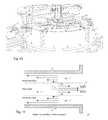
- FIG. 9A cross section of an electromechanical reactor.
- FIG. 10A partial cross section of a machine design incorporating elements of this description.
- FIG. 11A simplified overview of radial counterflow in the workspace.
- This disclosuredescribes an improved method of extracting the light fractions from the vortex cores in a radial counterflow regime.
- FIG. 1shows a top view cross section of the workspace 8 between two counter-rotating disk impellers, or disks, in a tank 1 , with the bottom disk visible at 3 .
- the counter-rotation of the disk impellerswill create a network of vortices in the workspace, shown as 8 in FIG. 2 , either from the motion of the disk surfaces alone, or with the assistance of structures such as textured surfaces, or protruding vanes.
- a vane coupled to the bottom diskis shown at 5
- a vane coupled to the top diskis shown at 7 .
- vortices 11will tend to form along the radial lanes of intersection 13 .
- a static axial exhaust array 15includes a plurality of exhaust channels 17 , each aligned with one of these lanes of intersection for sucking out the cores of the vortices.
- the exhaust array and feed arraycould be implemented as a continuous disk shaped, or continuous static structure. These exhaust channels each have a peripheral end 4 facing toward the workspace, and an inner end 6 , leading to an axial exhaust drain 19 .
- a plurality of feed channels 21 to allow a fluid mixture feed to enter the workspace between the lanes of intersection 13can be fed by an axial feed pipe 23 and a main feed line 25 .
- FIG. 2shows a partial cross section of the tank 1 enclosing the top disk 2 and the bottom disk 3 . Vanes on the bottom disk 5 and the top disk, as they pass in close proximity during counter-rotation 9 , will tend to form vortices 11 along the lanes of intersection.
- the lane of intersection region of vortex activitywill also be denoted as a dashed line in these drawings.
- Each lane of intersectionis aligned to an exhaust channel 17 in an axial exhaust array 15 which leads to an axial exhaust drain 19 approximately centered on the axis of rotation 27 .
- Feed channels 21 fed by a main feed line 25 and axial feed pipes 23 , making up the feed array,can introduce the feed into the workspace, especially between the lanes of intersection, where the feed flow will interfere less with the vortex formation.
- the feed channel 21is shown above the exhaust channel, and for simplicity, shown as coplanar in this cross section, although as shown in FIG. 1 , this would not actually be the case.
- the feed channels, besides being between the exhaust channels,could be located above or below them, or both above and below, or coplanar with the exhaust channels, as well as above and below them.
- the feed channelscan be axial, or from the periphery of the workspace, such as from a peripheral feed line 29 , leading to upper peripheral feed channels 31 , coplanar peripheral feed channels 33 , and lower peripheral feed channels 35 relative to the plane of the exhaust channels.
- An exhaust pump 37 on the axial exhaust drain 19causes low pressure in the exhaust channels 17 to attract the vortices to be fixed by their ends 12 shown in FIG. 1 to the peripheral ends 4 of the exhaust channels.
- a feed pump 39is used to introduce the feed through the feed channels.
- Motors and drive means for the bottom disk 41 and the top disk 43produce counter-rotation in the disks centered on the axis of rotation 27 , while the feed and exhaust assemblies remain static, and can be implemented as a continuous static structure such as 15 .
- a curved vortex reflector 45 in the tank wall aligned to a lane of intersectionwill help to make the vortices cores rebound inward and improve the flow through the exhaust channels.
- FIG. 3is a cylindrical cross section of the workspace, looking outward from the center, showing passing vanes and the turbulence patterns they would generate. At their lanes of intersection, the mechanical forcing of the fluid motion from the vanes 5 , 7 will tend to form vortices 11 in the fluid mixture, whose cores 47 are the focus of the exhaust channels.
- the vane profileshould be designed to maximize this effect.
- FIG. 4is a top cross section of the workspace in the manner of FIG. 1 , with the vanes from the bottom disk 5 and the top disk 7 shown, forming radial lanes of intersection 13 which are the focus of the exhaust array 15 .
- the intersection of the vanes and how they form these radial lanesis shown here by multiple successive rotations of ten degrees each.
- the direction of rotation of the disk 9 together with the angle of the vanes such as 14 relative to the lane of intersectioncombine to advect the fluid mixture, in this case in an advection direction outward 47 .
- FIG. 5is also a top cross section that shows the effect of a branching design for the vanes, wherein an added vane branch 49 produces added lanes of intersection 51 between the original lanes of intersection 13 .
- the counter-rotation 9 , 10 of the top and bottom vanesis shown in 22.5 degree increments. These added lanes of intersection 51 can be aligned to added exhaust channels 53 added to the axial exhaust assembly 15 .
- FIG. 6is a cross section of a detail of the patterns of the vortex layer 11 in the workspace, together with an exhaust channel 17 .
- the feedcan enter the workspace from a boundary layer 55 .
- the vortex core 57will be drawn into the exhaust channel 17 by low pressure, as part of an inwardly moving inner vortex 59 , surrounded by an outer vortex 61 moving outwardly toward the periphery, as part of a general outward flow 63 of the rejected heavier fractions.
- the exhaust channel 17 shown herehas a conical inner section 65 which concentrates and accelerates the vortex flow going into the channel, thereby increasing the centrifugal rejection of the heavier fractions.
- FIG. 7shows an alternate configuration for the design of an exhaust channel 17 with a conical outer portion 67 to help to strip away and reject the outer layers of the overall vortex.
- FIG. 8is a cross section of the exhaust assembly 15 showing angled exhaust channels 17 , having an angle 18 from what would be a straight exhaust channel, which help create a central exhaust vortex 69 for the most efficient exhaust flow.
- FIG. 9shows a cross section of an electromechanical reactor according to the present disclosure, combined with the description in the previously cited U.S. Pat. No. 8,025,801.
- the disks 2 , 3each have vanes 5 , 7 and are counter-rotated 9 , 10 to produce a vortex layer 11 leading to exhaust channels 17 , which in this case are angled conical angled holes to produce an exhaust vortex 69 in a static central pipe 71 .
- This central pipeis divided vertically here into an upper feed section and a lower exhaust section.
- the upper feed sectionhas a feed channel 25 leading to feed channels 21 , which in this case also have a conical design.
- This designis for an electromagnetic desalinator, with a static radio frequency induction coil 73 combined with a metal electromagnetic reflection layer 75 . These elements create differential motion in the salts and electrolytes in brine while leaving pure water unaffected, to aid in the separation and extraction of the water.
- FIG. 10shows a partial cross section of a machine design incorporating elements of this description.
- the tank 1encloses the disks, such as the top disk 2 .
- the axial exhaust assembly 15 and axial exhaust drain 19are between the two counter-rotating sets of vanes, such as the top vane 7 , which also has a branch 49 .
- a vortex reflector 45is at the edge of the workspace to help reflect the cores of the vortices back toward the axis.
- a single peripheral drive motor 77is used here, with a peripheral drive wheel 79 which contacts the top and bottom disks simultaneously, driving them in counter-rotation at the same time as the wheel turns.
- FIG. 11shows a simplified overview of radial counterflow in the workspace, bounded by the disks 2 , 3 showing motion vectors for the flow of the components in the shear layer 81 between the boundary layers 83 , and an axial exhaust channel 17 near the axis of rotation 27 .
- the separation profile of the diskscan different than the parallel disks shown here.
- the diskscan flare toward the periphery to form a much wider gap there than near the axis. Any vanes would also conform to the flared disk profile. This can allow for a different type of vortex formation process in the workspace, with a wider and slower vortex at the edge leading to a faster and narrower vortex toward the center.
- the variable disk profilecan also be reversed, with a wider disk separation toward the center than at the periphery.
- the vanes describedcan be built into the disk surfaces or be attached as separate parts.
- the angle of the vanescan be varied from the examples shown here. For example, if a C-shaped vane were centered on a line of intersection, the vane's rotation could serve to first advect the feed outward from the axis of rotation, then slow the outward advection down to a standstill, and then advect it inward from the region nearer to the periphery.
- Another alternativeis an S-shaped vane.
- the control of the rate of outward or inward advectionsallows for the optimal control of residence time and feed flow for the vortex separation processing.
- the low pressure in the exhaust channelscan be produced also by pressurizing the tank and the workspace relative to the lower pressure in the axial exhaust.
- the fluid mixture feedcan be gaseous, such as a flue gas feed with soot and other heavy fraction pollutants mixed with fresh air, or be liquid, such as a brine or water with sediment. It can also be a mix of the two, such as steam with entrained water droplets, or liquid with gaseous bubbles, especially the kind that emerge from the liquid with low pressure. Slurries can also be used, with the liquid extracted through the exhaust channels. This extraction mechanism can also be used for separation of fractions with differing viscosity, with the lighter viscosity fractions concentrating in the vortex cores. It can also be used for high temperature applications, such as the separation of molten components in a furnace.
- the rejected heavy fractions that exit the workspace into the tankare then disposed of by suitable means, while the extracted light fractions are used separately.
- Multiple devicescan be used in a chain, such as by having the light fractions from one stage used as the feed in another stage.
- the design of each stagecan be different depending on the nature of the feed, such as having a sediment extraction stage followed by a brine desalination stage.
- the partsshould be made of a suitable material for the application to be used.
- refractory materialswould be used for the separation of molten materials
- corrosion resistant componentswould be used for a corrosive feed. All of the components should be designed for durability and easy maintenance.
Landscapes
- Chemical & Material Sciences (AREA)
- Chemical Kinetics & Catalysis (AREA)
- Structures Of Non-Positive Displacement Pumps (AREA)
Abstract
Description
- 1. Enclosing tank
- 2. Upper disk
- 3. Lower disk
- 4. Peripheral end of exhaust channel
- 5. Lower disk vanes
- 6. Inner end of exhaust channel
- 7. Upper disk vanes
- 8. Workspace
- 9. Rotation for upper disk
- 10. Rotation for lower disk
- 11. Region of vortices in workspace
- 12. Vortex end
- 13. Lane of intersection
- 15. Exhaust array
- 17. Exhaust channel
- 18. Angle of exhaust channel
- 19. Axial exhaust drain
- 21. Feed channel
- 23. Axial feed pipe
- 25. Main feed channel
- 27. Axis of rotation
- 29. Peripheral feed pipe
- 31. Upper peripheral feed channel
- 33. Coplanar peripheral feed channel
- 35. Lower peripheral feed channel
- 37. Exhaust pump
- 39. Feed pump
- 41. Lower rotation drive
- 43. Upper rotation drive
- 45. Vortex reflector
- 47. Vortex core
- 49. Branch on vane
- 51. Additional lane of intersection
- 53. Additional exhaust channel aligned to additional lane
- 55. Feed through boundary layer
- 57. Flow through vortex core
- 59. Inward flowing vortex
- 61. Outward flowing vortex
- 63. Overall flow to periphery
- 65. Conical surface on inside of exhaust channel
- 67. Conical surface on outside of exhaust channel
- 69. Exhaust vortex
- 71. Static central pipe
- 73. Metal reflector
- 75. Induction coil
- 77. Peripheral drive
- 79. Peripheral drive wheel
- 81. Shear layer
- 83. Boundary layer
Claims (20)
Priority Applications (1)
| Application Number | Priority Date | Filing Date | Title |
|---|---|---|---|
| US15/664,855US10537840B2 (en) | 2017-07-31 | 2017-07-31 | Radial counterflow separation filter with focused exhaust |
Applications Claiming Priority (1)
| Application Number | Priority Date | Filing Date | Title |
|---|---|---|---|
| US15/664,855US10537840B2 (en) | 2017-07-31 | 2017-07-31 | Radial counterflow separation filter with focused exhaust |
Publications (2)
| Publication Number | Publication Date |
|---|---|
| US20190030474A1 US20190030474A1 (en) | 2019-01-31 |
| US10537840B2true US10537840B2 (en) | 2020-01-21 |
Family
ID=65138544
Family Applications (1)
| Application Number | Title | Priority Date | Filing Date |
|---|---|---|---|
| US15/664,855Active2037-10-18US10537840B2 (en) | 2017-07-31 | 2017-07-31 | Radial counterflow separation filter with focused exhaust |
Country Status (1)
| Country | Link |
|---|---|
| US (1) | US10537840B2 (en) |
Cited By (1)
| Publication number | Priority date | Publication date | Assignee | Title |
|---|---|---|---|---|
| US20220347603A1 (en)* | 2021-04-30 | 2022-11-03 | Pall Corporation | Filter disk segments |
Citations (267)
| Publication number | Priority date | Publication date | Assignee | Title |
|---|---|---|---|---|
| US406968A (en) | 1889-07-16 | And alfred s | ||
| US512340A (en) | 1893-07-07 | 1894-01-09 | Nikola Tesla | Coil for electro-magnets |
| US1952281A (en) | 1931-12-12 | 1934-03-27 | Giration Des Fluides Sarl | Method and apparatus for obtaining from alpha fluid under pressure two currents of fluids at different temperatures |
| US2422882A (en) | 1942-11-04 | 1947-06-24 | Bramley Arthur | Separation of fluids by simultaneous centrifugation and selective diffusion |
| US2685335A (en) | 1950-10-26 | 1954-08-03 | Coleman Co | Burner assembly |
| US2764095A (en) | 1954-02-05 | 1956-09-25 | Mine Safety Appliances Co | Polyphase electromagnetic induction pump |
| US2867945A (en) | 1955-10-19 | 1959-01-13 | Harold B Gotaas | Process of photosynthetic conversion of organic waste by algal-bacterial symbiosis |
| US3187898A (en) | 1962-12-26 | 1965-06-08 | Swimquip Inc | Automatic spin filter |
| US3366564A (en) | 1965-02-02 | 1968-01-30 | Gen Electric | Electrohydraulic process |
| US3411447A (en) | 1967-04-07 | 1968-11-19 | Kaiser Aluminium Chem Corp | Repulsion induction pump |
| US3465187A (en) | 1967-06-05 | 1969-09-02 | Onezime Philip Breaux | Homopolar generator having parallel positioned faraday disk structures |
| US3464672A (en) | 1966-10-26 | 1969-09-02 | Dynamics Corp America | Sonic processing transducer |
| US3468614A (en) | 1966-03-15 | 1969-09-23 | Goran Alfred Nilsson | Method and apparatus for bringing gases,liquids and/or pulverized solid bodies into intimate contact with each other |
| US3491023A (en) | 1967-12-01 | 1970-01-20 | Submersible Systems Inc | Process for containment and deflection of aqueous surface pollutants |
| US3520649A (en) | 1967-09-28 | 1970-07-14 | James P Tomany | System for removal of so2 and fly ash from power plant flue gases |
| US3566610A (en) | 1968-09-23 | 1971-03-02 | Cosmo Dominic Fiore | Method and apparatus for separating fluids |
| US3603062A (en) | 1968-11-21 | 1971-09-07 | Gen Electric | Gas-liquid separator |
| US3717554A (en) | 1969-03-29 | 1973-02-20 | Siemens Ag | Device for reclaiming sweet water from sea water or brackish water |
| US3731800A (en) | 1970-11-27 | 1973-05-08 | Polaroid Corp | Counter-current centrifugal device and use |
| US3755644A (en) | 1972-06-27 | 1973-08-28 | Growth Int Inc | High frequency induction heating apparatus |
| US3769781A (en) | 1970-10-20 | 1973-11-06 | Siemens Ag | Apparatus for drying steam in nuclear power steam generators plants |
| US3902876A (en) | 1972-07-21 | 1975-09-02 | Gen Electric | Gas-liquid vortex separator |
| US3915673A (en) | 1969-04-10 | 1975-10-28 | Doryokuro Kakunenryo | Method and apparatus for separating gas mixture by centrifuging |
| US3922871A (en) | 1974-04-15 | 1975-12-02 | Dmytro Bolesta | Heating and cooling by separation of faster from slower molecules of a gas |
| US3944865A (en) | 1973-05-25 | 1976-03-16 | Reyrolle Parsons Limited | Homopolar dynamo-electric machines |
| US3959923A (en) | 1974-12-04 | 1976-06-01 | Erno Raumfahrttechnik Gmbh | Equipment for growing algae |
| US3982378A (en) | 1975-03-13 | 1976-09-28 | Sohre Joachim S | Energy conversion device |
| US3990968A (en) | 1971-08-19 | 1976-11-09 | Desares Stiftung Fur Forderung Der Forschung Zur Entsalzung Des Wassers | Means for increasing the flow across a reverse osmosis membrane using an alternating electric field |
| US3990631A (en) | 1974-11-04 | 1976-11-09 | Schall Wallace J | Centrifugal scraper and separator apparatus |
| US3999400A (en) | 1970-07-10 | 1976-12-28 | Gray Vernon H | Rotating heat pipe for air-conditioning |
| US4037414A (en) | 1976-07-23 | 1977-07-26 | Nicodemus Carl D | Liquid/vapor energy cycle |
| US4044943A (en) | 1976-06-21 | 1977-08-30 | Kobe, Inc. | Centrifugal separator and system |
| US4076617A (en) | 1971-04-22 | 1978-02-28 | Tii Corporation | Sonic cavitation and ozonation of waste material |
| US4125439A (en) | 1977-05-31 | 1978-11-14 | National Research Development Corporation | Electrochemical cells and methods of electrolysis |
| US4184084A (en) | 1978-02-24 | 1980-01-15 | Robert Crehore | Wind driven gas generator |
| US4186089A (en) | 1977-05-16 | 1980-01-29 | Kurita Water Industries Limited | Method and apparatus for dewatering of sludgy substance |
| US4201635A (en) | 1977-12-21 | 1980-05-06 | Bbc Brown Boveri & Company Limited | Method and apparatus for carrying out an electrolysis process |
| US4272011A (en) | 1977-08-10 | 1981-06-09 | Hitachi, Ltd. | Centrifugal counterflow type contactor |
| US4273562A (en) | 1979-10-01 | 1981-06-16 | A. Ahlstrom Osakeyhtio | Method and apparatus for pumping gaseous liquids and separating the gaseous components therefrom |
| US4292051A (en) | 1979-03-29 | 1981-09-29 | Kime Wellesley R | Apparatus and method for centrifugal fluid separator |
| US4324068A (en) | 1980-03-03 | 1982-04-13 | Sax Zzyzx, Ltd. | Production of algae |
| US4326666A (en) | 1978-07-05 | 1982-04-27 | Hitachi, Ltd. | Centrifugal type counterflow contact apparatus |
| US4333017A (en) | 1980-10-20 | 1982-06-01 | Connell John J O | Method and apparatus for closed loop vortex operation |
| US4341038A (en) | 1979-07-03 | 1982-07-27 | Bloch Moshe R | Oil products from algae |
| US4357152A (en) | 1979-07-02 | 1982-11-02 | Progressive Development, Inc. | Fluid borne particulate separator |
| US4362020A (en) | 1981-02-11 | 1982-12-07 | Mechanical Technology Incorporated | Hermetic turbine generator |
| US4363540A (en) | 1976-01-30 | 1982-12-14 | Canon Kabushiki Kaisha | Exposure information storage device for a photographic camera |
| US4371382A (en) | 1980-08-06 | 1983-02-01 | Caribbean Properties Limited | Process and apparatus for the contact and separation of immiscible fluids |
| US4454101A (en) | 1982-11-24 | 1984-06-12 | Tennessee Valley Authority | Dewatering of flue gas desulfurization sulfite solids |
| US4458153A (en) | 1982-09-13 | 1984-07-03 | Wesley Richard H | Organism destruction by electrohydraulic discharge within a pulsed magnetic field envelope |
| US4479354A (en) | 1979-08-20 | 1984-10-30 | Thomas Cosby | Limited expansion vapor cycle |
| US4490252A (en) | 1976-04-01 | 1984-12-25 | Brigante Miguel F | Electrostatic scale control apparatus for feed water having rotating helix responsive to water flow rate |
| US4582513A (en) | 1979-12-28 | 1986-04-15 | Shell Oil Company | Centrifugal pump for the supply of finely divided solids |
| US4604109A (en) | 1983-10-03 | 1986-08-05 | Pall Corporation | Fluid purifier |
| US4668383A (en) | 1984-03-28 | 1987-05-26 | Cyrogenic Consultants Limited | Magnetic separator |
| US4680314A (en) | 1985-08-30 | 1987-07-14 | Microbio Resources, Inc. | Process for producing a naturally-derived carotene/oil composition by direct extraction from algae |
| US4792438A (en) | 1986-11-25 | 1988-12-20 | Inpal Co., Ltd. | Rotary type ozonizer |
| US4832918A (en) | 1986-06-12 | 1989-05-23 | Inpal Co., Ltd. | Rotary ozonizer |
| EP0319699A2 (en) | 1987-11-30 | 1989-06-14 | General Electric Company | Steam injected engine with auxillary high pressure steam turbine |
| US4846780A (en) | 1988-08-10 | 1989-07-11 | Exxon Production Research Company | Centrifuge processor and liquid level control system |
| US4925557A (en) | 1989-04-14 | 1990-05-15 | Ahlberg Jr Walter F | Multi-purpose rotating membrane filter |
| US4957606A (en) | 1987-07-28 | 1990-09-18 | Juvan Christian H A | Separation of dissolved and undissolved substances from liquids using high energy discharge initiated shock waves |
| US4992246A (en) | 1988-01-10 | 1991-02-12 | O.C. Engineering Co., Ltd. | Ozonizer |
| US4995425A (en) | 1990-05-11 | 1991-02-26 | Weisenbarger Gale M | Magnetic fluid conditioner |
| US4999597A (en) | 1990-02-16 | 1991-03-12 | Motorola, Inc. | Bifilar planar inductor |
| US5073262A (en) | 1989-04-14 | 1991-12-17 | Ahlberg Walter F | Multi-purpose rotating membrane filter |
| US5078847A (en) | 1990-08-29 | 1992-01-07 | Jerry Grosman | Ion plating method and apparatus |
| US5133190A (en) | 1991-01-25 | 1992-07-28 | Abdelmalek Fawzy T | Method and apparatus for flue gas cleaning by separation and liquefaction of sulfur dioxide and carbon dioxide |
| US5137681A (en) | 1990-05-23 | 1992-08-11 | Michael Dougherty | Method and apparatus for recycling turbine exhaust steam in electrical power generation |
| US5143630A (en) | 1991-05-30 | 1992-09-01 | Membrex, Inc. | Rotary disc filtration device |
| US5232726A (en) | 1992-10-08 | 1993-08-03 | The Coca-Cola Company | Ultra-high pressure homogenization of unpasteurized juice |
| US5254250A (en) | 1991-05-30 | 1993-10-19 | Membrex, Inc. | Rotary filtration device and filter pack therefor |
| US5275006A (en) | 1992-08-13 | 1994-01-04 | Mccutchen Wilmot H | Rotary two-phase refrigeration apparatus and method |
| US5368724A (en) | 1993-01-29 | 1994-11-29 | Pulsed Power Technologies, Inc. | Apparatus for treating a confined liquid by means of a pulse electrical discharge |
| US5390740A (en) | 1993-12-17 | 1995-02-21 | Texaco Inc. | Method and apparatus to recycle production well casing vapor |
| US5393421A (en) | 1992-02-14 | 1995-02-28 | Nippon Zoki Pharmaceutical Co., Ltd. | Apparatus for activating silicic acid in water |
| US5393417A (en) | 1992-03-02 | 1995-02-28 | Cox; Dale W. | Water remediation and purification system and method |
| US5441102A (en) | 1994-01-26 | 1995-08-15 | Sun Microsystems, Inc. | Heat exchanger for electronic equipment |
| US5449249A (en) | 1990-02-15 | 1995-09-12 | Husten; Peter F. | Methods and apparatus for decontamination of subsoil |
| US5451825A (en) | 1994-01-10 | 1995-09-19 | Strohm Systems, Inc. | Voltage homopolar machine |
| US5464513A (en) | 1994-01-11 | 1995-11-07 | Scientific Utilization, Inc. | Method and apparatus for water decontamination using electrical discharge |
| US5466270A (en) | 1992-11-16 | 1995-11-14 | Abdelmalek; Fawzy T. | Cyclonic centrifugal gas separator - absorber apparatus for boiler flue gas cleaning |
| US5476537A (en) | 1994-06-20 | 1995-12-19 | Rockwell International Corporation | Separation of chemical species of a mixture using vortex separation |
| US5481149A (en) | 1993-11-12 | 1996-01-02 | Toyota Jidosha Kabushiki Kaisha | Homopolar dynamoelectric machine |
| US5534118A (en) | 1992-08-13 | 1996-07-09 | Mccutchen; Wilmot H. | Rotary vacuum distillation and desalination apparatus |
| US5554343A (en) | 1991-01-29 | 1996-09-10 | Wade; Brian | Particle and light and heavy fluid separator |
| US5578280A (en) | 1995-04-28 | 1996-11-26 | Americal Environmental Technologies, Inc. | Ozone generator with a generally spherical corona chamber |
| US5587618A (en) | 1993-04-15 | 1996-12-24 | Hathaway; George D. | Direct current homopolar machine |
| US5607562A (en) | 1993-10-12 | 1997-03-04 | Permelec Electrode Ltd. | Electrolytic ozone generator |
| US5611214A (en) | 1994-07-29 | 1997-03-18 | Battelle Memorial Institute | Microcomponent sheet architecture |
| US5622621A (en) | 1994-03-29 | 1997-04-22 | United Technologies Corporation | Fluid/liquid separator |
| US5679249A (en) | 1991-12-24 | 1997-10-21 | Pall Corporation | Dynamic filter system |
| US5688377A (en) | 1992-08-13 | 1997-11-18 | Mccutchen; Wilmot H. | Rotary radial cyclonic fluid mixture separator |
| US5725778A (en) | 1995-10-17 | 1998-03-10 | Electronic Descaling 2000, Inc. | Current driver for electronic descaling |
| US5728186A (en) | 1995-10-12 | 1998-03-17 | Jonsson; Kjartan A. | Waste gas treatment apparatus |
| US5746789A (en) | 1995-11-28 | 1998-05-05 | Innovatech, Inc. | Apparatus for separating particulates from a fluid stream |
| US5817218A (en) | 1995-01-04 | 1998-10-06 | Fujitsu Limited | Gas reactor using a plasma for cracking or synthesizing gases |
| US5824136A (en) | 1993-09-10 | 1998-10-20 | Societe Generale Pour Les Techniques Nouvelles Sgn | Process for the purification of a gas by scrubbing -- Venturi column for carrying out said process |
| US5851375A (en) | 1994-08-05 | 1998-12-22 | Ennotech Holdings Limited | Apparatus for disinfecting fluids |
| US5851407A (en) | 1996-12-04 | 1998-12-22 | Applied Process Technolgy, Inc. | Process and apparatus for oxidation of contaminants in water |
| US5882530A (en) | 1997-04-30 | 1999-03-16 | The University Of Akron | Crossflow filter cyclone apparatus |
| US5902224A (en) | 1997-03-14 | 1999-05-11 | Fuge Systems, Inc. | Mass-mass cell gas centrifuge |
| US5925324A (en) | 1996-09-30 | 1999-07-20 | Paradigm Technologies | Magnetohydrodynamic sterilization method and apparatus |
| US5939030A (en) | 1997-05-08 | 1999-08-17 | Moxley; Douglas A. | System and method for generating ozonated water |
| US5993674A (en) | 1998-02-24 | 1999-11-30 | Membrex, Inc. | Rotary disc filtration device with means to reduce axial forces |
| US6019825A (en) | 1995-10-18 | 2000-02-01 | Gnesys, Inc. | Hydrocyclone gas separator |
| US6037170A (en) | 1996-12-30 | 2000-03-14 | Sekine; Toshirou | Apparatus for culturing microalgae |
| US6051905A (en) | 1998-09-17 | 2000-04-18 | Clark; Richard | Homopolar generator |
| US6116027A (en) | 1998-09-29 | 2000-09-12 | Air Products And Chemicals, Inc. | Supplemental air supply for an air separation system |
| US6117322A (en) | 1993-06-23 | 2000-09-12 | Pall Corporation | Dynamic filter system |
| US6149573A (en) | 1996-09-05 | 2000-11-21 | Balcon, Inc. | Centrifugal separator having a clutch assembly |
| US6183714B1 (en) | 1995-09-08 | 2001-02-06 | Rice University | Method of making ropes of single-wall carbon nanotubes |
| US6200486B1 (en) | 1999-04-02 | 2001-03-13 | Dynaflow, Inc. | Fluid jet cavitation method and system for efficient decontamination of liquids |
| US6203814B1 (en) | 1994-12-08 | 2001-03-20 | Hyperion Catalysis International, Inc. | Method of making functionalized nanotubes |
| US6208512B1 (en) | 1999-05-14 | 2001-03-27 | International Business Machines Corporation | Contactless hermetic pump |
| GB2354462A (en) | 1999-09-22 | 2001-03-28 | Mantis Oil Separation Ltd | Vortex device for separating oil or floating algae from water; combinations of separators |
| US6221260B1 (en) | 1999-04-02 | 2001-04-24 | Dynaflow, Inc. | Swirling fluid jet cavitation method and system for efficient decontamination of liquids |
| US6245299B1 (en) | 1997-11-25 | 2001-06-12 | State Of Israel - Ministry Of Defense Rafael Armament Development Authority | Modular dielectric barrier discharge device for pollution abatement |
| US6254764B1 (en) | 1996-11-05 | 2001-07-03 | E/P Technologies | Method for dissociating materials |
| US6261525B1 (en) | 2000-05-17 | 2001-07-17 | Bruce Minaee | Process gas decomposition reactor |
| US6264898B1 (en) | 1997-11-19 | 2001-07-24 | The Titan Corporation | Pulsed corona discharge apparatus |
| US6284105B1 (en) | 1999-06-17 | 2001-09-04 | Abb Research Ltd. | Dielectric barrier discharge cracking |
| US6292085B1 (en) | 1999-04-09 | 2001-09-18 | Electronic Descaling 2000, Inc. | Multiple coil assembly for use with electronic descaling unit |
| US6294139B1 (en) | 1994-09-21 | 2001-09-25 | Lab S.A. | Methods for wet cleaning or purifying gases or fumes to remove gaseous pollutants |
| US6350890B1 (en) | 1998-07-22 | 2002-02-26 | Axiva Gmbh | Method for obtaining fatty acids from biomass by combined in/situ extraction, reaction and chromatography using compressed gases |
| US6376558B1 (en) | 2000-01-06 | 2002-04-23 | Babcock-Bsh Gmbh | Method of producing a porous paste, especially a porous plaster slurry, and a mixer for preparing such paste or slurry |
| US6451175B1 (en) | 2000-08-15 | 2002-09-17 | Wisconsin Alumni Research Foundation | Method and apparatus for carbon nanotube production |
| US6468499B1 (en) | 2000-06-09 | 2002-10-22 | Argonne National Laboratory | Method of generating hydrogen by catalytic decomposition of water |
| US6478969B2 (en) | 1996-09-06 | 2002-11-12 | Pall Corporation | Shear separation method and system |
| US6484503B1 (en) | 2000-01-12 | 2002-11-26 | Arie Raz | Compression and condensation of turbine exhaust steam |
| US6494935B2 (en) | 2000-12-14 | 2002-12-17 | Vortex Aircon, Inc. | Vortex generator |
| US6495133B1 (en) | 1998-09-30 | 2002-12-17 | Her Majesty The Queen In Right Of Canada, As Represented By The Minister Of Agriculture & Agri-Food Canada | Gliocladium roseum strains useful for the control of fungal pathogens in plants |
| US6515391B2 (en) | 1999-05-20 | 2003-02-04 | The United States Of America As Represented By The Secretary Of The Navy | Electricity generator with counter-rotating collectors in a radial magnetic field |
| US6516617B1 (en) | 1999-04-14 | 2003-02-11 | Joachim Schwieger | Method for transforming heat using a vortex aggregate |
| US6517612B1 (en)* | 2001-10-29 | 2003-02-11 | Gore Enterprise Holdings, Inc. | Centrifugal filtration device |
| US6550531B1 (en) | 2000-05-16 | 2003-04-22 | Intel Corporation | Vapor chamber active heat sink |
| USRE38130E1 (en) | 1994-07-08 | 2003-06-03 | Amphion International Limited | Biological decontamination system |
| US6603233B2 (en) | 2001-07-20 | 2003-08-05 | Bryan W. Strohm | Electrical generator |
| US20030192831A1 (en) | 2002-04-10 | 2003-10-16 | Bertwin Langenecker | Inactivation of microorganisms and virus in liquids and sludge |
| US20040007539A1 (en) | 2002-07-12 | 2004-01-15 | Denes Ferencz S. | Method for disinfecting a dense fluid medium in a dense medium plasma reactor |
| US6685803B2 (en) | 2001-06-22 | 2004-02-03 | Applied Materials, Inc. | Plasma treatment of processing gases |
| US20040048364A1 (en) | 2000-10-06 | 2004-03-11 | Walter Trosch | Bio-reactor for the cultivation of micro-organisms and method for the production thereof |
| US6716335B2 (en) | 2000-12-19 | 2004-04-06 | Tominaga Mfg. Co. | Method of producing electrolyzed water |
| US6716269B1 (en) | 2002-03-05 | 2004-04-06 | Energent Corporation | Centrifuge and cascade for the separation of gases |
| USH2102H1 (en) | 1996-06-24 | 2004-05-04 | The United States Of America As Represented By The Secretary Of The Navy | Contamination control of gaseous emissions by corona-discharge generation of plasma |
| US6737099B2 (en) | 2001-03-29 | 2004-05-18 | The United States Of America As Represented By The Secretary Of Agriculture | Process for the deagglomeration and the homogeneous dispersion of starch particles |
| US6746613B2 (en) | 2002-11-04 | 2004-06-08 | Steris Inc. | Pulsed electric field system for treatment of a fluid medium |
| US6751940B1 (en) | 2001-05-08 | 2004-06-22 | Marius Paul | High efficiency gas turbine power generator |
| US6765949B2 (en) | 2000-03-07 | 2004-07-20 | Robert P. H. Chang | Carbon nanostructures and methods of preparation |
| US20040144314A1 (en) | 2003-01-23 | 2004-07-29 | 3M Innovative Properties Company | Plasma reactor including helical electrodes |
| US20040151654A1 (en) | 2001-05-25 | 2004-08-05 | Fei Wei | Continuous mass production of carbon nanotubes in a nano-agglomerate fluidized-bed and the reactor |
| US6774335B2 (en) | 2000-05-12 | 2004-08-10 | Hokushin Corporation | Plasma reactor and gas modification method |
| US6777639B2 (en) | 2002-06-12 | 2004-08-17 | Nanotechnologies, Inc. | Radial pulsed arc discharge gun for synthesizing nanopowders |
| US6808634B1 (en) | 1999-02-08 | 2004-10-26 | Andritz Ag | Method and device for cross-flow filtration |
| US6827820B1 (en) | 1999-06-03 | 2004-12-07 | Pom Technology Oy Ab | Degassing centrifugal apparatus, process for pumping and degassing a fluid and process for producing paper or board |
| US20040261417A1 (en) | 2003-04-30 | 2004-12-30 | Kabushiki Kaisha Toshiba | Steam turbine, steam turbine plant and method of operating a steam turbine in a steam turbine plant |
| US20050006801A1 (en) | 2003-07-11 | 2005-01-13 | Cambridge University Technical Service Limited | Production of agglomerates from gas phase |
| US6856037B2 (en) | 2001-11-26 | 2005-02-15 | Sony Corporation | Method and apparatus for converting dissipated heat to work energy |
| US6872301B2 (en) | 2001-12-20 | 2005-03-29 | Anthony Schepis | High shear rotating disc filter |
| US6875351B2 (en) | 2001-06-12 | 2005-04-05 | Hydrotreat, Inc. | Methods and apparatus for oil demulsification and separation of oil and suspended solids from produced water |
| US6894899B2 (en) | 2002-09-13 | 2005-05-17 | Hong Kong Cheung Tat Electrical Co. Ltd. | Integrated fluid cooling system for electronic components |
| US20050118090A1 (en) | 2002-01-24 | 2005-06-02 | Cambridge University Technical Services Limited | Plasma synthesis of hollow nanostructures |
| US20050133464A1 (en) | 2003-12-22 | 2005-06-23 | Technische Universitat Berlin | Apparatus and process for taking up particles from a water surface |
| US6916425B2 (en) | 1996-11-29 | 2005-07-12 | Pall Corporation | Mashing process |
| US6916418B2 (en) | 2002-03-13 | 2005-07-12 | Harris Acoustic Products Corporation | Assembly and method for purifying water at a point of use and apparatus and method for testing same |
| US20050163696A1 (en) | 2004-01-28 | 2005-07-28 | Uhm Han S. | Synthesis of carbon nanotubes by making use of microwave plasma torch |
| US6923890B2 (en) | 1999-12-15 | 2005-08-02 | Plasmasol Corporation | Chemical processing using non-thermal discharge plasma |
| US6924608B2 (en) | 2000-11-27 | 2005-08-02 | World Energy Systems Corporation | System and method for ignition and reignition of unstable electrical discharges |
| US20050170089A1 (en) | 2004-01-15 | 2005-08-04 | David Lashmore | Systems and methods for synthesis of extended length nanostructures |
| US6936228B2 (en) | 2003-02-27 | 2005-08-30 | Fuji Xerox Co., Ltd. | Manufacturing apparatus for carbon nanotube |
| US6943461B2 (en) | 2002-04-29 | 2005-09-13 | Solomon Kaploun | All-weather energy and water production via steam-enhanced vortex tower |
| US6945314B2 (en) | 2003-12-22 | 2005-09-20 | Lenovo Pte Ltd | Minimal fluid forced convective heat sink for high power computers |
| US6966874B2 (en) | 1997-10-14 | 2005-11-22 | Erth Technologies, Inc. | Concentric tubular centrifuge |
| US6979433B1 (en) | 2001-05-16 | 2005-12-27 | University Of Kentucky Research Foundation | Synthesis of multi-wall carbon nanotubes using unseeded hydrocarbon diffusion flames |
| US20060010871A1 (en) | 2003-11-14 | 2006-01-19 | The Trustees Of Columbia University In The City Of New York | Microfabricated rankine cycle steam turbine for power generation and methods of making the same |
| US7002800B2 (en) | 2002-01-25 | 2006-02-21 | Lockheed Martin Corporation | Integrated power and cooling architecture |
| US7006605B1 (en) | 1996-06-28 | 2006-02-28 | Ochopee Big Cypress Llc | Authenticating a caller before providing the caller with access to one or more secured resources |
| US7008605B1 (en) | 2001-11-08 | 2006-03-07 | The United States Of America As Represented By The Administrator Of The National Aeronautics And Space Administration | Method for manufacturing high quality carbon nanotubes |
| US20060057037A1 (en) | 2001-06-01 | 2006-03-16 | Fuji Xerox Co., Ltd. | Producing apparatus and producing method for manufacturing carbon structure |
| US7029584B2 (en) | 2000-07-13 | 2006-04-18 | Aaflowsystems Gmbh & Co. Kg | Rotating filter |
| US7033481B1 (en) | 2004-02-04 | 2006-04-25 | Bioionix, Inc. | Electroionic processing system |
| US7033478B2 (en) | 2002-09-10 | 2006-04-25 | Christina Harde | Ion separation and removal unit with gas extraction |
| US7035104B2 (en) | 2002-08-06 | 2006-04-25 | Mudawar Thermal Systems Inc. | Apparatus for heat transfer and critical heat flux enhancement |
| US7037484B1 (en) | 2002-06-21 | 2006-05-02 | University Of Central Florida Research Foundation, Inc. | Plasma reactor for cracking ammonia and hydrogen-rich gases to hydrogen |
| US7041144B2 (en) | 2003-03-04 | 2006-05-09 | Five Star Technologies, Inc. | Hydrodynamic cavitation crystallization process |
| US7049724B2 (en) | 2004-03-03 | 2006-05-23 | General Electric Company | Superconducting rotating machines with stationary field coils and axial airgap flux |
| US7052667B2 (en) | 2001-10-30 | 2006-05-30 | Materials And Electrochemical Research (Mer) Corporation | RF plasma method for production of single walled carbon nanotubes |
| US7056437B2 (en) | 2001-11-12 | 2006-06-06 | Emu Unterwasserpumpen Gmbh | Method and device for the treatment of effluent, sludge and organic substrates |
| US7055581B1 (en) | 2003-06-24 | 2006-06-06 | Roy Sanjay K | Impeller driven active heat sink |
| US20060127299A1 (en) | 2002-11-15 | 2006-06-15 | Mcgill University | Method for producing carbon nanotubes using a dc non-transferred thermal plasma torch |
| US7062900B1 (en) | 2003-06-26 | 2006-06-20 | Southwest Research Institute | Single wheel radial flow gas turbine |
| US20060146644A1 (en) | 1999-10-26 | 2006-07-06 | Holloway Michael A | System for producing micro-cluster liquids |
| US7094381B1 (en) | 2003-01-08 | 2006-08-22 | James Michael Overton | Device for destroying microbes in a fluid |
| US7097676B2 (en) | 2001-06-26 | 2006-08-29 | Norman Wootan | Process and device for producing hydrogen |
| US7121906B2 (en) | 2004-11-30 | 2006-10-17 | Carrier Corporation | Method and apparatus for decreasing marine vessel power plant exhaust temperature |
| US7128816B2 (en) | 2000-06-14 | 2006-10-31 | Wisconsin Alumni Research Foundation | Method and apparatus for producing colloidal nanoparticles in a dense medium plasma |
| US20060244386A1 (en) | 2005-05-02 | 2006-11-02 | Hooke William M | Pulsed dielectric barrier discharge |
| US20060251564A1 (en) | 2004-12-31 | 2006-11-09 | Industrial Technology Research Institute | Carbon nanomaterial purification method |
| US7150836B2 (en) | 2004-07-16 | 2006-12-19 | Battelle Energy Alliance, Llc | Microwave-emitting rotor, separator apparatus including same, methods of operation and design thereof |
| US20070001462A1 (en) | 2003-04-15 | 2007-01-04 | H-Empower Corp. | Integrated renewable energy system |
| US7160426B2 (en) | 2005-03-01 | 2007-01-09 | Wang Baosheng | Water treatment apparatus |
| US7169305B2 (en) | 2001-11-27 | 2007-01-30 | Rodolfo Antonio M Gomez | Advanced liquid vortex separation system |
| US7174715B2 (en) | 2005-02-02 | 2007-02-13 | Siemens Power Generation, Inc. | Hot to cold steam transformer for turbine systems |
| US7183515B2 (en) | 2004-12-20 | 2007-02-27 | Lockhead-Martin Corporation | Systems and methods for plasma jets |
| US20070045168A1 (en) | 2005-08-18 | 2007-03-01 | Clean Filtration Technologies, Inc. | Hydroclone based fluid filtration system |
| US20070048209A1 (en) | 1997-03-07 | 2007-03-01 | William Marsh Rice University | Continuous fiber of fullerene nanotubes |
| US20070048859A1 (en) | 2005-08-25 | 2007-03-01 | Sunsource Industries | Closed system bioreactor apparatus |
| US20070102111A1 (en) | 2003-08-18 | 2007-05-10 | President And Fellows Of Harvard College | Controlled nanotube fabrication and uses |
| US7217638B2 (en) | 2003-05-29 | 2007-05-15 | Nitto Denko Corporation | Wafer back surface treating method and dicing sheet adhering apparatus |
| US7217368B2 (en) | 2001-12-10 | 2007-05-15 | Clearwater Systems Corporation | Method and apparatus for liquid treatment with combined electronic and centrifugal processes to remove contaminants |
| US7238289B2 (en) | 2001-05-30 | 2007-07-03 | Hydro Municipal Technologies, Ltd. | Fluid treatment apparatus |
| US20070155006A1 (en) | 2005-12-30 | 2007-07-05 | Alexander Levin | Photobioreactor |
| US7241256B2 (en) | 2003-08-30 | 2007-07-10 | Erth Technologies, Inc. | Centrifuge |
| US7244360B2 (en) | 2001-10-23 | 2007-07-17 | Drexel University | Water treatment process |
| US20070163702A1 (en) | 2004-04-27 | 2007-07-19 | Steven Sullivan | Systems and methods of manufacturing nanotube structures |
| US7247244B2 (en) | 2004-10-20 | 2007-07-24 | Five Star Technologies, Inc. | Water treatment processes and devices utilizing hydrodynamic cavitation |
| US20070183959A1 (en) | 2003-03-20 | 2007-08-09 | Armines Association Pour la Recherche et le Development des Methodes et Processis Industriels | Carbon nanostructures and process for the production of carbon-based nanotubes, nanofibres and nanostructures |
| US7262384B2 (en) | 2004-09-30 | 2007-08-28 | Novacentrix, Corp. | Reaction vessel and method for synthesizing nanoparticles using cyclonic gas flow |
| US7263836B2 (en) | 2004-05-18 | 2007-09-04 | Schlumberger Technology Corporation | Vortex tube cooling system |
| US7264849B2 (en) | 2003-07-11 | 2007-09-04 | Optisolar, Inc. | Roll-vortex plasma chemical vapor deposition method |
| US20070224107A1 (en) | 2004-04-23 | 2007-09-27 | Sumitomo Electric Industries, Ltd. | Method of Manufacturing Carbon Nanostructure |
| US20070231886A1 (en) | 2006-03-28 | 2007-10-04 | Sartorius Ag | Reactor plant and process for culturing phototropic microorganisms |
| US20070237959A1 (en) | 2005-09-06 | 2007-10-11 | Lemaire Charles A | Apparatus and method for growing fullerene nanotube forests, and forming nanotube films, threads and composite structures therefrom |
| US7310232B2 (en) | 2005-12-30 | 2007-12-18 | Igor Victorovich Touzov | Multi-surface heat sink film |
| US7314516B2 (en) | 2004-12-29 | 2008-01-01 | Five Star Technologies, Inc. | Hydrodynamic cavitation crystallization device and process |
| WO2008007750A1 (en) | 2006-07-13 | 2008-01-17 | Osaka Industrial Promotion Organization | Process for producing carbon nanostructure and gas for carbon nanostructure production |
| US20080023338A1 (en) | 2006-07-31 | 2008-01-31 | Battelle Energy Alliance, Llc | High temperature electrolysis for syngas production |
| US7352580B2 (en) | 2006-02-14 | 2008-04-01 | Hua-Hsin Tsai | CPU cooler |
| US20080086969A1 (en) | 2002-02-20 | 2008-04-17 | Kemlite Corporation | Reinforced decorative composite material |
| US7374731B2 (en) | 2005-09-02 | 2008-05-20 | Yonyu Plastics Co., Ltd. | Reaction apparatus for producing vapor-grown carbon fibers and continuous production system thereof |
| US7374685B2 (en) | 2003-12-18 | 2008-05-20 | Clemson University | Process for separating metallic from semiconducting single-walled carbon nanotubes |
| US7374693B1 (en) | 2005-11-25 | 2008-05-20 | Routberg Rutberg Alexander F | Water decontamination apparatus and method |
| US7381328B2 (en) | 2002-07-05 | 2008-06-03 | Commissart A L'energie Atomique | Effluent treatment combining solid/liquid separation and pulsed electric fields |
| US20080170982A1 (en) | 2004-11-09 | 2008-07-17 | Board Of Regents, The University Of Texas System | Fabrication and Application of Nanofiber Ribbons and Sheets and Twisted and Non-Twisted Nanofiber Yarns |
| US7408186B2 (en) | 2002-02-06 | 2008-08-05 | Ut-Battelle Llc | Controlled alignment catalytically grown nanostructures |
| US20090013867A1 (en) | 2007-07-11 | 2009-01-15 | Mccutchen Wilmot H | Radial counterflow carbon capture and flue gas scrubbing |
| US7479325B2 (en) | 2002-11-27 | 2009-01-20 | Tsinghua University | Isotope-doped carbon nanotube |
| US20090045150A1 (en) | 2007-08-16 | 2009-02-19 | Mccutchen Wilmot H | Radial counterflow inductive desalination |
| US20090060827A1 (en) | 2005-05-03 | 2009-03-05 | Vincenzo Vinciguerra | Method for growing carbon nanatubes having a predetermined chirality |
| US20090068727A1 (en) | 2007-08-28 | 2009-03-12 | Greg Karr | Closed system, shallow channel photobioreactor |
| US20090087371A1 (en) | 2007-09-28 | 2009-04-02 | Suk-Won Jang | Apparatus for manufacturing carbon nanotubes and method of manufacturing carbon nanotubes with the same |
| US20090113790A1 (en) | 2007-11-01 | 2009-05-07 | Erd Ronald A | Algae production |
| US20090155864A1 (en) | 2007-12-14 | 2009-06-18 | Alan Joseph Bauer | Systems, methods, and devices for employing solar energy to produce biofuels |
| US20090159523A1 (en) | 2007-12-20 | 2009-06-25 | Mccutchen Wilmot H | Rotary annular crossflow filter, degasser, and sludge thickener |
| US20090159461A1 (en)* | 2007-12-20 | 2009-06-25 | Mccutchen Co. | Electrohydraulic and shear cavitation radial counterflow liquid processor |
| US20090200176A1 (en) | 2008-02-07 | 2009-08-13 | Mccutchen Co. | Radial counterflow shear electrolysis |
| US20090242174A1 (en)* | 2008-03-31 | 2009-10-01 | Mccutchen Co. | Vapor vortex heat sink |
| US20090246863A1 (en) | 2008-04-01 | 2009-10-01 | Chien-Feng Lin | Apparatus for cultivating oil-rich microalgae |
| US20090256175A1 (en) | 2008-04-11 | 2009-10-15 | Samsung Electronics Co., Ltd. | Method of doping transistor comprising carbon nanotube, method of controlling position of doping ion, and transistors using the same |
| WO2009142765A2 (en) | 2008-05-23 | 2009-11-26 | Orginoil, Inc. | Apparatus and methods for photosynthetic growth of microorganisms in a photobioreactor |
| US20090317901A1 (en) | 2008-06-19 | 2009-12-24 | Adrian George Vance | Fuel farm |
| US20100005711A1 (en) | 2008-07-09 | 2010-01-14 | Sartec Corporation | Lighted Algae Cultivation Systems |
| US20100093046A1 (en) | 2006-07-18 | 2010-04-15 | Hyperthermics Holding As | Energy production with hyperthermophilic organisms |
| US20100093074A1 (en) | 2008-10-14 | 2010-04-15 | William Frederick Tooley | Floating Oxygenation Circulator Platform (OCP) with Sub-Vortex Induction Means |
| US20100162620A1 (en) | 2008-12-19 | 2010-07-01 | Mccaffrey William | Optimization of Algal Product Production through Uncoupling Cell Proliferation and Algal Product Production |
| US20100178231A1 (en) | 2006-12-22 | 2010-07-15 | Turney Christian Stewart Macgregor | Method of Sequestering Carbon Dioxide |
| US20100190241A1 (en) | 2008-12-23 | 2010-07-29 | Param Jaggi | Bioactive carbon dioxide filter apparatus and method therefor |
| US7771582B2 (en) | 2003-05-19 | 2010-08-10 | Hydro Dnamics, Inc. | Method and apparatus for conducting a chemical reaction in the presence of cavitation and an electrical current |
| US20100227388A1 (en) | 2009-03-04 | 2010-09-09 | Oleg Shvabsky | Reactor for growing cultures |
| US7794969B1 (en) | 2009-07-09 | 2010-09-14 | Joule Unlimited, Inc. | Methods and compositions for the recombinant biosynthesis of n-alkanes |
| US20100255569A1 (en) | 2009-04-02 | 2010-10-07 | Camarate De Albuquerque Maranhao Andre | Algae photobioreactor |
| US20100273252A1 (en) | 2009-04-23 | 2010-10-28 | Chien-Feng Lin | Algae cultivation apparatus |
| US7851211B2 (en) | 2007-03-07 | 2010-12-14 | Chao-Hui Lu | Alga microbe photosynthetic reaction system |
| US20100330615A1 (en) | 2007-05-02 | 2010-12-30 | Dolivar Coraucci Neto | Process to produce biodiesel and/or fuel oil |
| US7883580B2 (en) | 2008-04-02 | 2011-02-08 | Raythedn Company | System and method for nanotube growth via Ion implantation using a catalytic transmembrane |
| US7987677B2 (en) | 2008-03-31 | 2011-08-02 | Mccutchen Co. | Radial counterflow steam stripper |
| US20120196336A1 (en) | 2011-01-28 | 2012-08-02 | Mccutchen Co. | Radial counterflow reactor with applied radiant energy |
- 2017
- 2017-07-31USUS15/664,855patent/US10537840B2/enactiveActive
Patent Citations (283)
| Publication number | Priority date | Publication date | Assignee | Title |
|---|---|---|---|---|
| US406968A (en) | 1889-07-16 | And alfred s | ||
| US512340A (en) | 1893-07-07 | 1894-01-09 | Nikola Tesla | Coil for electro-magnets |
| US1952281A (en) | 1931-12-12 | 1934-03-27 | Giration Des Fluides Sarl | Method and apparatus for obtaining from alpha fluid under pressure two currents of fluids at different temperatures |
| US2422882A (en) | 1942-11-04 | 1947-06-24 | Bramley Arthur | Separation of fluids by simultaneous centrifugation and selective diffusion |
| US2685335A (en) | 1950-10-26 | 1954-08-03 | Coleman Co | Burner assembly |
| US2764095A (en) | 1954-02-05 | 1956-09-25 | Mine Safety Appliances Co | Polyphase electromagnetic induction pump |
| US2867945A (en) | 1955-10-19 | 1959-01-13 | Harold B Gotaas | Process of photosynthetic conversion of organic waste by algal-bacterial symbiosis |
| US3187898A (en) | 1962-12-26 | 1965-06-08 | Swimquip Inc | Automatic spin filter |
| US3366564A (en) | 1965-02-02 | 1968-01-30 | Gen Electric | Electrohydraulic process |
| US3468614A (en) | 1966-03-15 | 1969-09-23 | Goran Alfred Nilsson | Method and apparatus for bringing gases,liquids and/or pulverized solid bodies into intimate contact with each other |
| US3464672A (en) | 1966-10-26 | 1969-09-02 | Dynamics Corp America | Sonic processing transducer |
| US3411447A (en) | 1967-04-07 | 1968-11-19 | Kaiser Aluminium Chem Corp | Repulsion induction pump |
| US3465187A (en) | 1967-06-05 | 1969-09-02 | Onezime Philip Breaux | Homopolar generator having parallel positioned faraday disk structures |
| US3520649A (en) | 1967-09-28 | 1970-07-14 | James P Tomany | System for removal of so2 and fly ash from power plant flue gases |
| US3491023A (en) | 1967-12-01 | 1970-01-20 | Submersible Systems Inc | Process for containment and deflection of aqueous surface pollutants |
| US3566610A (en) | 1968-09-23 | 1971-03-02 | Cosmo Dominic Fiore | Method and apparatus for separating fluids |
| US3603062A (en) | 1968-11-21 | 1971-09-07 | Gen Electric | Gas-liquid separator |
| US3717554A (en) | 1969-03-29 | 1973-02-20 | Siemens Ag | Device for reclaiming sweet water from sea water or brackish water |
| US3915673A (en) | 1969-04-10 | 1975-10-28 | Doryokuro Kakunenryo | Method and apparatus for separating gas mixture by centrifuging |
| US3999400A (en) | 1970-07-10 | 1976-12-28 | Gray Vernon H | Rotating heat pipe for air-conditioning |
| US3769781A (en) | 1970-10-20 | 1973-11-06 | Siemens Ag | Apparatus for drying steam in nuclear power steam generators plants |
| US3731800A (en) | 1970-11-27 | 1973-05-08 | Polaroid Corp | Counter-current centrifugal device and use |
| US4076617A (en) | 1971-04-22 | 1978-02-28 | Tii Corporation | Sonic cavitation and ozonation of waste material |
| US3990968A (en) | 1971-08-19 | 1976-11-09 | Desares Stiftung Fur Forderung Der Forschung Zur Entsalzung Des Wassers | Means for increasing the flow across a reverse osmosis membrane using an alternating electric field |
| US3755644A (en) | 1972-06-27 | 1973-08-28 | Growth Int Inc | High frequency induction heating apparatus |
| US3902876A (en) | 1972-07-21 | 1975-09-02 | Gen Electric | Gas-liquid vortex separator |
| US3944865A (en) | 1973-05-25 | 1976-03-16 | Reyrolle Parsons Limited | Homopolar dynamo-electric machines |
| US3922871A (en) | 1974-04-15 | 1975-12-02 | Dmytro Bolesta | Heating and cooling by separation of faster from slower molecules of a gas |
| US3990631A (en) | 1974-11-04 | 1976-11-09 | Schall Wallace J | Centrifugal scraper and separator apparatus |
| US3959923A (en) | 1974-12-04 | 1976-06-01 | Erno Raumfahrttechnik Gmbh | Equipment for growing algae |
| US3982378A (en) | 1975-03-13 | 1976-09-28 | Sohre Joachim S | Energy conversion device |
| US4363540A (en) | 1976-01-30 | 1982-12-14 | Canon Kabushiki Kaisha | Exposure information storage device for a photographic camera |
| US4490252A (en) | 1976-04-01 | 1984-12-25 | Brigante Miguel F | Electrostatic scale control apparatus for feed water having rotating helix responsive to water flow rate |
| US4044943A (en) | 1976-06-21 | 1977-08-30 | Kobe, Inc. | Centrifugal separator and system |
| US4037414A (en) | 1976-07-23 | 1977-07-26 | Nicodemus Carl D | Liquid/vapor energy cycle |
| US4186089A (en) | 1977-05-16 | 1980-01-29 | Kurita Water Industries Limited | Method and apparatus for dewatering of sludgy substance |
| US4125439A (en) | 1977-05-31 | 1978-11-14 | National Research Development Corporation | Electrochemical cells and methods of electrolysis |
| US4272011A (en) | 1977-08-10 | 1981-06-09 | Hitachi, Ltd. | Centrifugal counterflow type contactor |
| US4201635A (en) | 1977-12-21 | 1980-05-06 | Bbc Brown Boveri & Company Limited | Method and apparatus for carrying out an electrolysis process |
| US4184084A (en) | 1978-02-24 | 1980-01-15 | Robert Crehore | Wind driven gas generator |
| US4326666A (en) | 1978-07-05 | 1982-04-27 | Hitachi, Ltd. | Centrifugal type counterflow contact apparatus |
| US4292051A (en) | 1979-03-29 | 1981-09-29 | Kime Wellesley R | Apparatus and method for centrifugal fluid separator |
| US4357152A (en) | 1979-07-02 | 1982-11-02 | Progressive Development, Inc. | Fluid borne particulate separator |
| US4341038A (en) | 1979-07-03 | 1982-07-27 | Bloch Moshe R | Oil products from algae |
| US4479354A (en) | 1979-08-20 | 1984-10-30 | Thomas Cosby | Limited expansion vapor cycle |
| US4273562A (en) | 1979-10-01 | 1981-06-16 | A. Ahlstrom Osakeyhtio | Method and apparatus for pumping gaseous liquids and separating the gaseous components therefrom |
| US4582513A (en) | 1979-12-28 | 1986-04-15 | Shell Oil Company | Centrifugal pump for the supply of finely divided solids |
| US4324068A (en) | 1980-03-03 | 1982-04-13 | Sax Zzyzx, Ltd. | Production of algae |
| US4371382A (en) | 1980-08-06 | 1983-02-01 | Caribbean Properties Limited | Process and apparatus for the contact and separation of immiscible fluids |
| US4333017A (en) | 1980-10-20 | 1982-06-01 | Connell John J O | Method and apparatus for closed loop vortex operation |
| US4362020A (en) | 1981-02-11 | 1982-12-07 | Mechanical Technology Incorporated | Hermetic turbine generator |
| US4458153A (en) | 1982-09-13 | 1984-07-03 | Wesley Richard H | Organism destruction by electrohydraulic discharge within a pulsed magnetic field envelope |
| US4454101A (en) | 1982-11-24 | 1984-06-12 | Tennessee Valley Authority | Dewatering of flue gas desulfurization sulfite solids |
| US4604109A (en) | 1983-10-03 | 1986-08-05 | Pall Corporation | Fluid purifier |
| US4668383A (en) | 1984-03-28 | 1987-05-26 | Cyrogenic Consultants Limited | Magnetic separator |
| US4680314A (en) | 1985-08-30 | 1987-07-14 | Microbio Resources, Inc. | Process for producing a naturally-derived carotene/oil composition by direct extraction from algae |
| US4832918A (en) | 1986-06-12 | 1989-05-23 | Inpal Co., Ltd. | Rotary ozonizer |
| US4792438A (en) | 1986-11-25 | 1988-12-20 | Inpal Co., Ltd. | Rotary type ozonizer |
| US4957606A (en) | 1987-07-28 | 1990-09-18 | Juvan Christian H A | Separation of dissolved and undissolved substances from liquids using high energy discharge initiated shock waves |
| EP0319699A2 (en) | 1987-11-30 | 1989-06-14 | General Electric Company | Steam injected engine with auxillary high pressure steam turbine |
| US4992246A (en) | 1988-01-10 | 1991-02-12 | O.C. Engineering Co., Ltd. | Ozonizer |
| US4846780A (en) | 1988-08-10 | 1989-07-11 | Exxon Production Research Company | Centrifuge processor and liquid level control system |
| US4925557A (en) | 1989-04-14 | 1990-05-15 | Ahlberg Jr Walter F | Multi-purpose rotating membrane filter |
| US5073262A (en) | 1989-04-14 | 1991-12-17 | Ahlberg Walter F | Multi-purpose rotating membrane filter |
| US5449249A (en) | 1990-02-15 | 1995-09-12 | Husten; Peter F. | Methods and apparatus for decontamination of subsoil |
| US4999597A (en) | 1990-02-16 | 1991-03-12 | Motorola, Inc. | Bifilar planar inductor |
| US4995425A (en) | 1990-05-11 | 1991-02-26 | Weisenbarger Gale M | Magnetic fluid conditioner |
| US5137681A (en) | 1990-05-23 | 1992-08-11 | Michael Dougherty | Method and apparatus for recycling turbine exhaust steam in electrical power generation |
| US5078847A (en) | 1990-08-29 | 1992-01-07 | Jerry Grosman | Ion plating method and apparatus |
| US5133190A (en) | 1991-01-25 | 1992-07-28 | Abdelmalek Fawzy T | Method and apparatus for flue gas cleaning by separation and liquefaction of sulfur dioxide and carbon dioxide |
| US5554343A (en) | 1991-01-29 | 1996-09-10 | Wade; Brian | Particle and light and heavy fluid separator |
| US5254250A (en) | 1991-05-30 | 1993-10-19 | Membrex, Inc. | Rotary filtration device and filter pack therefor |
| US5143630A (en) | 1991-05-30 | 1992-09-01 | Membrex, Inc. | Rotary disc filtration device |
| US6106713A (en) | 1991-12-24 | 2000-08-22 | Pall Corporation | Dynamic filter system |
| US5679249A (en) | 1991-12-24 | 1997-10-21 | Pall Corporation | Dynamic filter system |
| US5393421A (en) | 1992-02-14 | 1995-02-28 | Nippon Zoki Pharmaceutical Co., Ltd. | Apparatus for activating silicic acid in water |
| US5494585A (en) | 1992-03-02 | 1996-02-27 | Cox; Dale W. | Water remediation and purification system and method |
| US5393417A (en) | 1992-03-02 | 1995-02-28 | Cox; Dale W. | Water remediation and purification system and method |
| US5275006A (en) | 1992-08-13 | 1994-01-04 | Mccutchen Wilmot H | Rotary two-phase refrigeration apparatus and method |
| US5534118A (en) | 1992-08-13 | 1996-07-09 | Mccutchen; Wilmot H. | Rotary vacuum distillation and desalination apparatus |
| US5688377A (en) | 1992-08-13 | 1997-11-18 | Mccutchen; Wilmot H. | Rotary radial cyclonic fluid mixture separator |
| US5232726A (en) | 1992-10-08 | 1993-08-03 | The Coca-Cola Company | Ultra-high pressure homogenization of unpasteurized juice |
| US5466270A (en) | 1992-11-16 | 1995-11-14 | Abdelmalek; Fawzy T. | Cyclonic centrifugal gas separator - absorber apparatus for boiler flue gas cleaning |
| US5368724A (en) | 1993-01-29 | 1994-11-29 | Pulsed Power Technologies, Inc. | Apparatus for treating a confined liquid by means of a pulse electrical discharge |
| US5587618A (en) | 1993-04-15 | 1996-12-24 | Hathaway; George D. | Direct current homopolar machine |
| US6117322A (en) | 1993-06-23 | 2000-09-12 | Pall Corporation | Dynamic filter system |
| US5824136A (en) | 1993-09-10 | 1998-10-20 | Societe Generale Pour Les Techniques Nouvelles Sgn | Process for the purification of a gas by scrubbing -- Venturi column for carrying out said process |
| US5607562A (en) | 1993-10-12 | 1997-03-04 | Permelec Electrode Ltd. | Electrolytic ozone generator |
| US5481149A (en) | 1993-11-12 | 1996-01-02 | Toyota Jidosha Kabushiki Kaisha | Homopolar dynamoelectric machine |
| US5390740A (en) | 1993-12-17 | 1995-02-21 | Texaco Inc. | Method and apparatus to recycle production well casing vapor |
| US5451825A (en) | 1994-01-10 | 1995-09-19 | Strohm Systems, Inc. | Voltage homopolar machine |
| US5464513A (en) | 1994-01-11 | 1995-11-07 | Scientific Utilization, Inc. | Method and apparatus for water decontamination using electrical discharge |
| US5441102A (en) | 1994-01-26 | 1995-08-15 | Sun Microsystems, Inc. | Heat exchanger for electronic equipment |
| US5622621A (en) | 1994-03-29 | 1997-04-22 | United Technologies Corporation | Fluid/liquid separator |
| US5476537A (en) | 1994-06-20 | 1995-12-19 | Rockwell International Corporation | Separation of chemical species of a mixture using vortex separation |
| USRE38130E1 (en) | 1994-07-08 | 2003-06-03 | Amphion International Limited | Biological decontamination system |
| US5611214A (en) | 1994-07-29 | 1997-03-18 | Battelle Memorial Institute | Microcomponent sheet architecture |
| US5851375A (en) | 1994-08-05 | 1998-12-22 | Ennotech Holdings Limited | Apparatus for disinfecting fluids |
| US6294139B1 (en) | 1994-09-21 | 2001-09-25 | Lab S.A. | Methods for wet cleaning or purifying gases or fumes to remove gaseous pollutants |
| US6203814B1 (en) | 1994-12-08 | 2001-03-20 | Hyperion Catalysis International, Inc. | Method of making functionalized nanotubes |
| US5817218A (en) | 1995-01-04 | 1998-10-06 | Fujitsu Limited | Gas reactor using a plasma for cracking or synthesizing gases |
| US5578280A (en) | 1995-04-28 | 1996-11-26 | Americal Environmental Technologies, Inc. | Ozone generator with a generally spherical corona chamber |
| US6183714B1 (en) | 1995-09-08 | 2001-02-06 | Rice University | Method of making ropes of single-wall carbon nanotubes |
| US5728186A (en) | 1995-10-12 | 1998-03-17 | Jonsson; Kjartan A. | Waste gas treatment apparatus |
| US5725778A (en) | 1995-10-17 | 1998-03-10 | Electronic Descaling 2000, Inc. | Current driver for electronic descaling |
| US6019825A (en) | 1995-10-18 | 2000-02-01 | Gnesys, Inc. | Hydrocyclone gas separator |
| US5746789A (en) | 1995-11-28 | 1998-05-05 | Innovatech, Inc. | Apparatus for separating particulates from a fluid stream |
| USH2102H1 (en) | 1996-06-24 | 2004-05-04 | The United States Of America As Represented By The Secretary Of The Navy | Contamination control of gaseous emissions by corona-discharge generation of plasma |
| US7006605B1 (en) | 1996-06-28 | 2006-02-28 | Ochopee Big Cypress Llc | Authenticating a caller before providing the caller with access to one or more secured resources |
| US6149573A (en) | 1996-09-05 | 2000-11-21 | Balcon, Inc. | Centrifugal separator having a clutch assembly |
| US6478969B2 (en) | 1996-09-06 | 2002-11-12 | Pall Corporation | Shear separation method and system |
| US5925324A (en) | 1996-09-30 | 1999-07-20 | Paradigm Technologies | Magnetohydrodynamic sterilization method and apparatus |
| US6254764B1 (en) | 1996-11-05 | 2001-07-03 | E/P Technologies | Method for dissociating materials |
| US6916425B2 (en) | 1996-11-29 | 2005-07-12 | Pall Corporation | Mashing process |
| US5851407A (en) | 1996-12-04 | 1998-12-22 | Applied Process Technolgy, Inc. | Process and apparatus for oxidation of contaminants in water |
| US6037170A (en) | 1996-12-30 | 2000-03-14 | Sekine; Toshirou | Apparatus for culturing microalgae |
| US20070048209A1 (en) | 1997-03-07 | 2007-03-01 | William Marsh Rice University | Continuous fiber of fullerene nanotubes |
| US5902224A (en) | 1997-03-14 | 1999-05-11 | Fuge Systems, Inc. | Mass-mass cell gas centrifuge |
| US5882530A (en) | 1997-04-30 | 1999-03-16 | The University Of Akron | Crossflow filter cyclone apparatus |
| US6210575B1 (en) | 1997-04-30 | 2001-04-03 | The University Of Akron | Crossflow filter cyclone apparatus |
| US5939030A (en) | 1997-05-08 | 1999-08-17 | Moxley; Douglas A. | System and method for generating ozonated water |
| US6966874B2 (en) | 1997-10-14 | 2005-11-22 | Erth Technologies, Inc. | Concentric tubular centrifuge |
| US6264898B1 (en) | 1997-11-19 | 2001-07-24 | The Titan Corporation | Pulsed corona discharge apparatus |
| US6245299B1 (en) | 1997-11-25 | 2001-06-12 | State Of Israel - Ministry Of Defense Rafael Armament Development Authority | Modular dielectric barrier discharge device for pollution abatement |
| US5993674A (en) | 1998-02-24 | 1999-11-30 | Membrex, Inc. | Rotary disc filtration device with means to reduce axial forces |
| US6350890B1 (en) | 1998-07-22 | 2002-02-26 | Axiva Gmbh | Method for obtaining fatty acids from biomass by combined in/situ extraction, reaction and chromatography using compressed gases |
| US6051905A (en) | 1998-09-17 | 2000-04-18 | Clark; Richard | Homopolar generator |
| US6116027A (en) | 1998-09-29 | 2000-09-12 | Air Products And Chemicals, Inc. | Supplemental air supply for an air separation system |
| US6495133B1 (en) | 1998-09-30 | 2002-12-17 | Her Majesty The Queen In Right Of Canada, As Represented By The Minister Of Agriculture & Agri-Food Canada | Gliocladium roseum strains useful for the control of fungal pathogens in plants |
| US6808634B1 (en) | 1999-02-08 | 2004-10-26 | Andritz Ag | Method and device for cross-flow filtration |
| US6221260B1 (en) | 1999-04-02 | 2001-04-24 | Dynaflow, Inc. | Swirling fluid jet cavitation method and system for efficient decontamination of liquids |
| US6200486B1 (en) | 1999-04-02 | 2001-03-13 | Dynaflow, Inc. | Fluid jet cavitation method and system for efficient decontamination of liquids |
| US6292085B1 (en) | 1999-04-09 | 2001-09-18 | Electronic Descaling 2000, Inc. | Multiple coil assembly for use with electronic descaling unit |
| US6516617B1 (en) | 1999-04-14 | 2003-02-11 | Joachim Schwieger | Method for transforming heat using a vortex aggregate |
| US6208512B1 (en) | 1999-05-14 | 2001-03-27 | International Business Machines Corporation | Contactless hermetic pump |
| US6515391B2 (en) | 1999-05-20 | 2003-02-04 | The United States Of America As Represented By The Secretary Of The Navy | Electricity generator with counter-rotating collectors in a radial magnetic field |
| US6827820B1 (en) | 1999-06-03 | 2004-12-07 | Pom Technology Oy Ab | Degassing centrifugal apparatus, process for pumping and degassing a fluid and process for producing paper or board |
| US6284105B1 (en) | 1999-06-17 | 2001-09-04 | Abb Research Ltd. | Dielectric barrier discharge cracking |
| GB2354462A (en) | 1999-09-22 | 2001-03-28 | Mantis Oil Separation Ltd | Vortex device for separating oil or floating algae from water; combinations of separators |
| US20060146644A1 (en) | 1999-10-26 | 2006-07-06 | Holloway Michael A | System for producing micro-cluster liquids |
| US6923890B2 (en) | 1999-12-15 | 2005-08-02 | Plasmasol Corporation | Chemical processing using non-thermal discharge plasma |
| US6376558B1 (en) | 2000-01-06 | 2002-04-23 | Babcock-Bsh Gmbh | Method of producing a porous paste, especially a porous plaster slurry, and a mixer for preparing such paste or slurry |
| US6484503B1 (en) | 2000-01-12 | 2002-11-26 | Arie Raz | Compression and condensation of turbine exhaust steam |
| US6765949B2 (en) | 2000-03-07 | 2004-07-20 | Robert P. H. Chang | Carbon nanostructures and methods of preparation |
| US6774335B2 (en) | 2000-05-12 | 2004-08-10 | Hokushin Corporation | Plasma reactor and gas modification method |
| US6550531B1 (en) | 2000-05-16 | 2003-04-22 | Intel Corporation | Vapor chamber active heat sink |
| US6261525B1 (en) | 2000-05-17 | 2001-07-17 | Bruce Minaee | Process gas decomposition reactor |
| US6468499B1 (en) | 2000-06-09 | 2002-10-22 | Argonne National Laboratory | Method of generating hydrogen by catalytic decomposition of water |
| US7128816B2 (en) | 2000-06-14 | 2006-10-31 | Wisconsin Alumni Research Foundation | Method and apparatus for producing colloidal nanoparticles in a dense medium plasma |
| US7029584B2 (en) | 2000-07-13 | 2006-04-18 | Aaflowsystems Gmbh & Co. Kg | Rotating filter |
| US6451175B1 (en) | 2000-08-15 | 2002-09-17 | Wisconsin Alumni Research Foundation | Method and apparatus for carbon nanotube production |
| US20040048364A1 (en) | 2000-10-06 | 2004-03-11 | Walter Trosch | Bio-reactor for the cultivation of micro-organisms and method for the production thereof |
| US6924608B2 (en) | 2000-11-27 | 2005-08-02 | World Energy Systems Corporation | System and method for ignition and reignition of unstable electrical discharges |
| US6494935B2 (en) | 2000-12-14 | 2002-12-17 | Vortex Aircon, Inc. | Vortex generator |
| US6716335B2 (en) | 2000-12-19 | 2004-04-06 | Tominaga Mfg. Co. | Method of producing electrolyzed water |
| US6737099B2 (en) | 2001-03-29 | 2004-05-18 | The United States Of America As Represented By The Secretary Of Agriculture | Process for the deagglomeration and the homogeneous dispersion of starch particles |
| US6751940B1 (en) | 2001-05-08 | 2004-06-22 | Marius Paul | High efficiency gas turbine power generator |
| US6979433B1 (en) | 2001-05-16 | 2005-12-27 | University Of Kentucky Research Foundation | Synthesis of multi-wall carbon nanotubes using unseeded hydrocarbon diffusion flames |
| US20040151654A1 (en) | 2001-05-25 | 2004-08-05 | Fei Wei | Continuous mass production of carbon nanotubes in a nano-agglomerate fluidized-bed and the reactor |
| US7238289B2 (en) | 2001-05-30 | 2007-07-03 | Hydro Municipal Technologies, Ltd. | Fluid treatment apparatus |
| US20060057037A1 (en) | 2001-06-01 | 2006-03-16 | Fuji Xerox Co., Ltd. | Producing apparatus and producing method for manufacturing carbon structure |
| US6875351B2 (en) | 2001-06-12 | 2005-04-05 | Hydrotreat, Inc. | Methods and apparatus for oil demulsification and separation of oil and suspended solids from produced water |
| US6685803B2 (en) | 2001-06-22 | 2004-02-03 | Applied Materials, Inc. | Plasma treatment of processing gases |
| US7097676B2 (en) | 2001-06-26 | 2006-08-29 | Norman Wootan | Process and device for producing hydrogen |
| US6603233B2 (en) | 2001-07-20 | 2003-08-05 | Bryan W. Strohm | Electrical generator |
| US7244360B2 (en) | 2001-10-23 | 2007-07-17 | Drexel University | Water treatment process |
| US7419603B2 (en) | 2001-10-23 | 2008-09-02 | Drexel University | Water treatment method |
| US6517612B1 (en)* | 2001-10-29 | 2003-02-11 | Gore Enterprise Holdings, Inc. | Centrifugal filtration device |
| US7052667B2 (en) | 2001-10-30 | 2006-05-30 | Materials And Electrochemical Research (Mer) Corporation | RF plasma method for production of single walled carbon nanotubes |
| US7008605B1 (en) | 2001-11-08 | 2006-03-07 | The United States Of America As Represented By The Administrator Of The National Aeronautics And Space Administration | Method for manufacturing high quality carbon nanotubes |
| US7056437B2 (en) | 2001-11-12 | 2006-06-06 | Emu Unterwasserpumpen Gmbh | Method and device for the treatment of effluent, sludge and organic substrates |
| US6856037B2 (en) | 2001-11-26 | 2005-02-15 | Sony Corporation | Method and apparatus for converting dissipated heat to work energy |
| US7169305B2 (en) | 2001-11-27 | 2007-01-30 | Rodolfo Antonio M Gomez | Advanced liquid vortex separation system |
| US7217368B2 (en) | 2001-12-10 | 2007-05-15 | Clearwater Systems Corporation | Method and apparatus for liquid treatment with combined electronic and centrifugal processes to remove contaminants |
| US6872301B2 (en) | 2001-12-20 | 2005-03-29 | Anthony Schepis | High shear rotating disc filter |
| US20050118090A1 (en) | 2002-01-24 | 2005-06-02 | Cambridge University Technical Services Limited | Plasma synthesis of hollow nanostructures |
| US7002800B2 (en) | 2002-01-25 | 2006-02-21 | Lockheed Martin Corporation | Integrated power and cooling architecture |
| US7408186B2 (en) | 2002-02-06 | 2008-08-05 | Ut-Battelle Llc | Controlled alignment catalytically grown nanostructures |
| US20080086969A1 (en) | 2002-02-20 | 2008-04-17 | Kemlite Corporation | Reinforced decorative composite material |
| US6716269B1 (en) | 2002-03-05 | 2004-04-06 | Energent Corporation | Centrifuge and cascade for the separation of gases |
| US6916418B2 (en) | 2002-03-13 | 2005-07-12 | Harris Acoustic Products Corporation | Assembly and method for purifying water at a point of use and apparatus and method for testing same |
| US20030192831A1 (en) | 2002-04-10 | 2003-10-16 | Bertwin Langenecker | Inactivation of microorganisms and virus in liquids and sludge |
| US7306737B2 (en) | 2002-04-10 | 2007-12-11 | Bertwin Langenecker | Inactivation of microorganisms and virus in liquids and sludge |
| US6943461B2 (en) | 2002-04-29 | 2005-09-13 | Solomon Kaploun | All-weather energy and water production via steam-enhanced vortex tower |
| US6777639B2 (en) | 2002-06-12 | 2004-08-17 | Nanotechnologies, Inc. | Radial pulsed arc discharge gun for synthesizing nanopowders |
| US7037484B1 (en) | 2002-06-21 | 2006-05-02 | University Of Central Florida Research Foundation, Inc. | Plasma reactor for cracking ammonia and hydrogen-rich gases to hydrogen |
| US7381328B2 (en) | 2002-07-05 | 2008-06-03 | Commissart A L'energie Atomique | Effluent treatment combining solid/liquid separation and pulsed electric fields |
| US20040007539A1 (en) | 2002-07-12 | 2004-01-15 | Denes Ferencz S. | Method for disinfecting a dense fluid medium in a dense medium plasma reactor |
| US7035104B2 (en) | 2002-08-06 | 2006-04-25 | Mudawar Thermal Systems Inc. | Apparatus for heat transfer and critical heat flux enhancement |
| US7033478B2 (en) | 2002-09-10 | 2006-04-25 | Christina Harde | Ion separation and removal unit with gas extraction |
| US6894899B2 (en) | 2002-09-13 | 2005-05-17 | Hong Kong Cheung Tat Electrical Co. Ltd. | Integrated fluid cooling system for electronic components |
| US6746613B2 (en) | 2002-11-04 | 2004-06-08 | Steris Inc. | Pulsed electric field system for treatment of a fluid medium |
| US20060127299A1 (en) | 2002-11-15 | 2006-06-15 | Mcgill University | Method for producing carbon nanotubes using a dc non-transferred thermal plasma torch |
| US7479325B2 (en) | 2002-11-27 | 2009-01-20 | Tsinghua University | Isotope-doped carbon nanotube |
| US7094381B1 (en) | 2003-01-08 | 2006-08-22 | James Michael Overton | Device for destroying microbes in a fluid |
| US20040144314A1 (en) | 2003-01-23 | 2004-07-29 | 3M Innovative Properties Company | Plasma reactor including helical electrodes |
| US6936228B2 (en) | 2003-02-27 | 2005-08-30 | Fuji Xerox Co., Ltd. | Manufacturing apparatus for carbon nanotube |
| US7041144B2 (en) | 2003-03-04 | 2006-05-09 | Five Star Technologies, Inc. | Hydrodynamic cavitation crystallization process |
| US20070183959A1 (en) | 2003-03-20 | 2007-08-09 | Armines Association Pour la Recherche et le Development des Methodes et Processis Industriels | Carbon nanostructures and process for the production of carbon-based nanotubes, nanofibres and nanostructures |
| US20070001462A1 (en) | 2003-04-15 | 2007-01-04 | H-Empower Corp. | Integrated renewable energy system |
| US20040261417A1 (en) | 2003-04-30 | 2004-12-30 | Kabushiki Kaisha Toshiba | Steam turbine, steam turbine plant and method of operating a steam turbine in a steam turbine plant |
| US7771582B2 (en) | 2003-05-19 | 2010-08-10 | Hydro Dnamics, Inc. | Method and apparatus for conducting a chemical reaction in the presence of cavitation and an electrical current |
| US7217638B2 (en) | 2003-05-29 | 2007-05-15 | Nitto Denko Corporation | Wafer back surface treating method and dicing sheet adhering apparatus |
| US7055581B1 (en) | 2003-06-24 | 2006-06-06 | Roy Sanjay K | Impeller driven active heat sink |
| US7062900B1 (en) | 2003-06-26 | 2006-06-20 | Southwest Research Institute | Single wheel radial flow gas turbine |
| US7264849B2 (en) | 2003-07-11 | 2007-09-04 | Optisolar, Inc. | Roll-vortex plasma chemical vapor deposition method |
| US7323157B2 (en) | 2003-07-11 | 2008-01-29 | Cambridge University Technical Services Limited | Production of agglomerates from gas phase |
| US20050006801A1 (en) | 2003-07-11 | 2005-01-13 | Cambridge University Technical Service Limited | Production of agglomerates from gas phase |
| US20070102111A1 (en) | 2003-08-18 | 2007-05-10 | President And Fellows Of Harvard College | Controlled nanotube fabrication and uses |
| US7241256B2 (en) | 2003-08-30 | 2007-07-10 | Erth Technologies, Inc. | Centrifuge |
| US20060010871A1 (en) | 2003-11-14 | 2006-01-19 | The Trustees Of Columbia University In The City Of New York | Microfabricated rankine cycle steam turbine for power generation and methods of making the same |
| US7374685B2 (en) | 2003-12-18 | 2008-05-20 | Clemson University | Process for separating metallic from semiconducting single-walled carbon nanotubes |
| US7163637B2 (en) | 2003-12-22 | 2007-01-16 | Technische Unversitat Berlin | Apparatus and process for taking up particles from a water surface |
| US6945314B2 (en) | 2003-12-22 | 2005-09-20 | Lenovo Pte Ltd | Minimal fluid forced convective heat sink for high power computers |
| US20050133464A1 (en) | 2003-12-22 | 2005-06-23 | Technische Universitat Berlin | Apparatus and process for taking up particles from a water surface |
| US20050170089A1 (en) | 2004-01-15 | 2005-08-04 | David Lashmore | Systems and methods for synthesis of extended length nanostructures |
| US20050163696A1 (en) | 2004-01-28 | 2005-07-28 | Uhm Han S. | Synthesis of carbon nanotubes by making use of microwave plasma torch |
| US7033481B1 (en) | 2004-02-04 | 2006-04-25 | Bioionix, Inc. | Electroionic processing system |
| US7049724B2 (en) | 2004-03-03 | 2006-05-23 | General Electric Company | Superconducting rotating machines with stationary field coils and axial airgap flux |
| US20070224107A1 (en) | 2004-04-23 | 2007-09-27 | Sumitomo Electric Industries, Ltd. | Method of Manufacturing Carbon Nanostructure |
| US20070163702A1 (en) | 2004-04-27 | 2007-07-19 | Steven Sullivan | Systems and methods of manufacturing nanotube structures |
| US7263836B2 (en) | 2004-05-18 | 2007-09-04 | Schlumberger Technology Corporation | Vortex tube cooling system |
| US7150836B2 (en) | 2004-07-16 | 2006-12-19 | Battelle Energy Alliance, Llc | Microwave-emitting rotor, separator apparatus including same, methods of operation and design thereof |
| US7262384B2 (en) | 2004-09-30 | 2007-08-28 | Novacentrix, Corp. | Reaction vessel and method for synthesizing nanoparticles using cyclonic gas flow |
| US7247244B2 (en) | 2004-10-20 | 2007-07-24 | Five Star Technologies, Inc. | Water treatment processes and devices utilizing hydrodynamic cavitation |
| US20080170982A1 (en) | 2004-11-09 | 2008-07-17 | Board Of Regents, The University Of Texas System | Fabrication and Application of Nanofiber Ribbons and Sheets and Twisted and Non-Twisted Nanofiber Yarns |
| US7121906B2 (en) | 2004-11-30 | 2006-10-17 | Carrier Corporation | Method and apparatus for decreasing marine vessel power plant exhaust temperature |
| US7183515B2 (en) | 2004-12-20 | 2007-02-27 | Lockhead-Martin Corporation | Systems and methods for plasma jets |
| US7314516B2 (en) | 2004-12-29 | 2008-01-01 | Five Star Technologies, Inc. | Hydrodynamic cavitation crystallization device and process |
| US20060251564A1 (en) | 2004-12-31 | 2006-11-09 | Industrial Technology Research Institute | Carbon nanomaterial purification method |
| US7174715B2 (en) | 2005-02-02 | 2007-02-13 | Siemens Power Generation, Inc. | Hot to cold steam transformer for turbine systems |
| US7160426B2 (en) | 2005-03-01 | 2007-01-09 | Wang Baosheng | Water treatment apparatus |
| US20060244386A1 (en) | 2005-05-02 | 2006-11-02 | Hooke William M | Pulsed dielectric barrier discharge |
| US20090060827A1 (en) | 2005-05-03 | 2009-03-05 | Vincenzo Vinciguerra | Method for growing carbon nanatubes having a predetermined chirality |
| US20070045168A1 (en) | 2005-08-18 | 2007-03-01 | Clean Filtration Technologies, Inc. | Hydroclone based fluid filtration system |
| US20070048859A1 (en) | 2005-08-25 | 2007-03-01 | Sunsource Industries | Closed system bioreactor apparatus |
| US20070048848A1 (en) | 2005-08-25 | 2007-03-01 | Sunsource Industries | Method, apparatus and system for biodiesel production from algae |
| US7374731B2 (en) | 2005-09-02 | 2008-05-20 | Yonyu Plastics Co., Ltd. | Reaction apparatus for producing vapor-grown carbon fibers and continuous production system thereof |
| US20070237959A1 (en) | 2005-09-06 | 2007-10-11 | Lemaire Charles A | Apparatus and method for growing fullerene nanotube forests, and forming nanotube films, threads and composite structures therefrom |
| US7374693B1 (en) | 2005-11-25 | 2008-05-20 | Routberg Rutberg Alexander F | Water decontamination apparatus and method |
| US7310232B2 (en) | 2005-12-30 | 2007-12-18 | Igor Victorovich Touzov | Multi-surface heat sink film |
| US20070155006A1 (en) | 2005-12-30 | 2007-07-05 | Alexander Levin | Photobioreactor |
| US7352580B2 (en) | 2006-02-14 | 2008-04-01 | Hua-Hsin Tsai | CPU cooler |
| US20070231886A1 (en) | 2006-03-28 | 2007-10-04 | Sartorius Ag | Reactor plant and process for culturing phototropic microorganisms |
| WO2008007750A1 (en) | 2006-07-13 | 2008-01-17 | Osaka Industrial Promotion Organization | Process for producing carbon nanostructure and gas for carbon nanostructure production |
| US20100093046A1 (en) | 2006-07-18 | 2010-04-15 | Hyperthermics Holding As | Energy production with hyperthermophilic organisms |
| US20080023338A1 (en) | 2006-07-31 | 2008-01-31 | Battelle Energy Alliance, Llc | High temperature electrolysis for syngas production |
| US20100178231A1 (en) | 2006-12-22 | 2010-07-15 | Turney Christian Stewart Macgregor | Method of Sequestering Carbon Dioxide |
| US7851211B2 (en) | 2007-03-07 | 2010-12-14 | Chao-Hui Lu | Alga microbe photosynthetic reaction system |
| US20100330615A1 (en) | 2007-05-02 | 2010-12-30 | Dolivar Coraucci Neto | Process to produce biodiesel and/or fuel oil |
| US20090013867A1 (en) | 2007-07-11 | 2009-01-15 | Mccutchen Wilmot H | Radial counterflow carbon capture and flue gas scrubbing |
| US7901485B2 (en) | 2007-07-11 | 2011-03-08 | Mccutchen Co. | Radial counterflow carbon capture and flue gas scrubbing |
| US8025801B2 (en) | 2007-08-16 | 2011-09-27 | Mccutchen Co. | Radial counterflow inductive desalination |
| US20090045150A1 (en) | 2007-08-16 | 2009-02-19 | Mccutchen Wilmot H | Radial counterflow inductive desalination |
| US20090068727A1 (en) | 2007-08-28 | 2009-03-12 | Greg Karr | Closed system, shallow channel photobioreactor |
| US20090087371A1 (en) | 2007-09-28 | 2009-04-02 | Suk-Won Jang | Apparatus for manufacturing carbon nanotubes and method of manufacturing carbon nanotubes with the same |
| US20090113790A1 (en) | 2007-11-01 | 2009-05-07 | Erd Ronald A | Algae production |
| US20090155864A1 (en) | 2007-12-14 | 2009-06-18 | Alan Joseph Bauer | Systems, methods, and devices for employing solar energy to produce biofuels |
| US20090159461A1 (en)* | 2007-12-20 | 2009-06-25 | Mccutchen Co. | Electrohydraulic and shear cavitation radial counterflow liquid processor |
| US7757866B2 (en) | 2007-12-20 | 2010-07-20 | Mccutchen Co. | Rotary annular crossflow filter, degasser, and sludge thickener |
| US8268136B2 (en) | 2007-12-20 | 2012-09-18 | McCutchen, Co. | Electrohydraulic and shear cavitation radial counterflow liquid processor |
| US20090159523A1 (en) | 2007-12-20 | 2009-06-25 | Mccutchen Wilmot H | Rotary annular crossflow filter, degasser, and sludge thickener |
| US9611556B2 (en) | 2008-02-07 | 2017-04-04 | Mccutchen Co. | Radial counterflow shear electrolysis |
| US20090200176A1 (en) | 2008-02-07 | 2009-08-13 | Mccutchen Co. | Radial counterflow shear electrolysis |
| US20090263309A1 (en) | 2008-02-07 | 2009-10-22 | Mccutchen Co. | Shear reactor for vortex synthesis of nanotubes |
| US7987677B2 (en) | 2008-03-31 | 2011-08-02 | Mccutchen Co. | Radial counterflow steam stripper |
| US7980078B2 (en) | 2008-03-31 | 2011-07-19 | Mccutchen Co. | Vapor vortex heat sink |
| US8474264B2 (en) | 2008-03-31 | 2013-07-02 | Mccutchen Co. | Radial counterflow steam stripper |
| US20090242174A1 (en)* | 2008-03-31 | 2009-10-01 | Mccutchen Co. | Vapor vortex heat sink |
| US20090246863A1 (en) | 2008-04-01 | 2009-10-01 | Chien-Feng Lin | Apparatus for cultivating oil-rich microalgae |
| US7883580B2 (en) | 2008-04-02 | 2011-02-08 | Raythedn Company | System and method for nanotube growth via Ion implantation using a catalytic transmembrane |
| US20090256175A1 (en) | 2008-04-11 | 2009-10-15 | Samsung Electronics Co., Ltd. | Method of doping transistor comprising carbon nanotube, method of controlling position of doping ion, and transistors using the same |
| WO2009142765A2 (en) | 2008-05-23 | 2009-11-26 | Orginoil, Inc. | Apparatus and methods for photosynthetic growth of microorganisms in a photobioreactor |
| US20090317901A1 (en) | 2008-06-19 | 2009-12-24 | Adrian George Vance | Fuel farm |
| US20100005711A1 (en) | 2008-07-09 | 2010-01-14 | Sartec Corporation | Lighted Algae Cultivation Systems |
| US20100093074A1 (en) | 2008-10-14 | 2010-04-15 | William Frederick Tooley | Floating Oxygenation Circulator Platform (OCP) with Sub-Vortex Induction Means |
| US20100162620A1 (en) | 2008-12-19 | 2010-07-01 | Mccaffrey William | Optimization of Algal Product Production through Uncoupling Cell Proliferation and Algal Product Production |
| US20100190241A1 (en) | 2008-12-23 | 2010-07-29 | Param Jaggi | Bioactive carbon dioxide filter apparatus and method therefor |
| US20100227388A1 (en) | 2009-03-04 | 2010-09-09 | Oleg Shvabsky | Reactor for growing cultures |
| US20100255569A1 (en) | 2009-04-02 | 2010-10-07 | Camarate De Albuquerque Maranhao Andre | Algae photobioreactor |
| US20100273252A1 (en) | 2009-04-23 | 2010-10-28 | Chien-Feng Lin | Algae cultivation apparatus |
| US7794969B1 (en) | 2009-07-09 | 2010-09-14 | Joule Unlimited, Inc. | Methods and compositions for the recombinant biosynthesis of n-alkanes |
| US20120196336A1 (en) | 2011-01-28 | 2012-08-02 | Mccutchen Co. | Radial counterflow reactor with applied radiant energy |
Non-Patent Citations (68)
| Title |
|---|
| "Algaewheel Brochure", retrieved at http://www.algaewheel.com (2012). |
| "All Biochar is Not Created Equally"; http://www.biocharsolutions.com/technology.html; printed on Feb. 13, 2012. |
| "Biochar Pathways for Different Environments"; International Biochar Initiative, Aug. 26, 2009, pp. 1-2. |
| Ahmed, et al., "Feasibility of Salt Production from Inland RO Desalination Plant Reject Brine: A Case Study," Desalination 158 (2003) pp. 109-117. |
| Bellucci et al., "Study of Field Emission of Multi-Walled C Nanotubes Synthesized by Arc Discharge", J. Phys: Condens. Matter 19 (2007) 395014 (7pp.), retrieved Mar. 20, 2009 from the Internet: URL<http://www.iop.org/EJ/abstract/0953-8984/19/39/395014>, Abstract. |
| Bergles, A. (May 2001). "The Implications and Challenges of Enhanced Heat Transfer for the Chemical Process Industries". Institution of Chemical Engineers, Trans IChemE, vol. 79, Part A, pp. 437-444. |
| Bockris, J., et al., "On the Splitting of Water," Int. J. Hydrogen Energy, vol. 10, No. 30, pp. 179-201, 1985, Bergamon Press Ltd., Great Britain. |
| Britt, Robert Roy, "The Worlds Smallest Motor," Apr. 12, 2005, retrieved at http://www.livescience.com/6969-world-smallest-motor.html. |
| Chen, C. et al., Cultivation, photobioreactor design and harvesting of microalgae for biodiesel production: A critical review; Bioresource Technology 102 (2011) 71-81. |
| Chen, J. et al., "Fractal-like free networks Increasing the permeability," Physical Review E 75, 056301 (2007) pp. 1-8. |
| Crocker et al., Experimental Results of a Vortex Tube Air Separator For Advanced Space Transportation, AIAA 2003-4451, 39th Joint Propulsion Conference & Exhibit, Huntsville, Alabama, Jul. 20-23, 2003, pp. 1-12. |
| Czernichowski, A., "GlidArc Assisted Preparation of the Synthesis Gas from Natural and Waste Hydrocarbons Gases," Oil & Gas Science Technology-Rev. IFP, vol. 56 No. 2 (2001), pp. 181-198. |
| Daniels, D., "Put a lid on rising chemical costs," Power, Sep. 15, 2008. pp. 1-9. |
| Daviaud et al., Turbulence in Rotating Flows, 2005, http://www-drecam.cea.fr/spec/Pres/Git/TRF/trf.htm, 2 pgs. |
| De La Torre et al., Slow Dynamics in a Turbulent von Karman Swirling Flow, arXiv:physics/0702151v1, Feb. 19, 2007.4 pgs. |
| Feeley, T. et al. (Jul. 2005). "Department of Energy/Office of Fossil Energy's Power Plant Water Management R&D Program". DOE/FE's Power Plant Water Management R&D Program Summary, pp. 1-14. |
| Flannigan, D. et al., "Sonochemistry and sonoluminescense in ionic liquids, molten salts, and concentrated electrolyte solutions," Journal of Organometallic Chemistry 690 (2005), pp. 3513-3517. |
| Gao, C. (2005). "Experimental Study on the Ranque-Hilsch Vortex Tube". CIP-Data Library Technische Universiteit Eindhoven, pp. 1-148. |
| Gupta, S., "Investigation of a physical disinfection process based on pulsed underwater corona discharges," retrieved at FZKA 7336 digbib.ubka.uni-karlsruhe.de/volitexte/documetns/23373.pdf, Sep. 2007, pp. 1-135. |
| Hawkes, G., et al., INL/CON-06-11720 Preprint, "Three Dimensional CFD Model of a Planar Solid Oxide Electrolysis Cell for Co-Electrolysis of Steam and Carbon Dioxide," Nov. 2006, Idaho National Laboratory, Idaho, US, including 2 pg. INL flyer entitled Syntrolysis. |
| Hellyar, K. (1979). "Gas Liquefaction Using a Ranque-Hilsch Vortex Teube: Design Criteria and Bibliography". Massachusetts Institute of Technology, pp. 1-68. |
| Hinkov, S., et al., "Optical Plasma Control During Arc Carbon Nanotube Growth" 2001, Proceedings of the Sixth Applied Diamond Conference/Second Frontier Carbon Technology Joint Conference (ADC/FCT 2001). |
| Hnatiuc, E. et al., "Cold Plasma Electrochemical Reactor with Rotary Discharge," retrieved at http://www.ut.ee/hakone8/papers/T6/Hnatiuc1(TP).pdf, Jul. 31, 2003, pp. 181-198. |
| Indarto, A., "Kinetic of CO2 Reduction by Gliding Arc Plasma," Asian Journal of Water, Environment and Pollution, vol. 4, No. 1, pp. 191-194, Oct. 9, 2006. |
| IPCC Special Report on Carbon Dioxide Capture and Storage, Chapter 3, Capture of CO2 (2005), pp. 108-122, 168-171. |
| Ivan Delbende et al., Various Aspects of Fluid Vortices, C.R. Mechanique 332 (2004) pp. 767-781. |
| Kalra, C.S. et al., "Gliding arc in tornado using a reverse vortex flow," Review of Scientific Instruments 76, 025110, pp. 1-7, Jan. 21, 2005, American Institute of Physics. |
| Keider, et al., "On the Conditions of Carbon Nanotube Growth in the Arc Discharge," Nanotechnology vol. 15 Issue 11, Oct. 1, 2004, pp. 1571-1575. |
| Khachatryan, A., et al., "Graphite-to-diamond transformation induced by ultrasound cavitation," Diamond & Related Materials 17 (2008), pp. 931-936. |
| Kim, S., et al., "Seed crystalization with cavitation for enhanced removal of calcium in water," J. Ind. Eng. Chem, vol. 13, No. 1 (2007), pp. 79-83. |
| King, Tao, "Direct numerical simulation of Open Von Karman Swirling Flow," ScienceDirect, J. Hydrodynamics, 2014, 26(2):166-178. |
| Konno, A., et al., "Observation of cavitation bubble collapse by high-speed video," retrieved at www.fluid.mech.kogakuin.ac.jp, Dec. 11, 2003, pp. 1-6. |
| Koziol et al., "High-Performance Carbon Nanotube Fiber", Science Express, 10.1261147635, Nov. 15, 2007, pp. 1-6. |
| Koziol et al., Cambridgenanotube1147635s1.mpg (identified as "Movie S1" in Koziol et al., High-Performance Carbon Nanotube Fiber, Science Express, 10.1261147635, Nov. 15, 2007, pp. 1-6.), CD-R, IBM-PC, MS Windows, 2.22 MB. |
| Koziol, K, et al., "High-Performance Carbon Nantube Fiber," Science, vol. 318, pp. 1892-1895, Dec. 21, 2007. |
| Kronenberg, K, "Experimental Evidence for Effects of Magnetic Fields on Moving Water," IEEE Transactions on Magnetics, vol. MAG-21, No. 5, Sep. 1985 pp. 2059-2061. |
| Kronenberg, Klaus J., "Experimental Evidence for Effects of Magnetic Fields on Moving Water," IEEE Transactions on Magnetics, vol. Mag-21, No. 5, Sep. 1985. |
| Lebovka, N., Vorobiev, E., "The kinetics of inactivation of spheroidal microbial cells by pulsed electric fields," arXiv 3704.2750v1, Apr. 20, 2007, pp. 1-22. |
| Lee, S.J., et al., "Large scale synthesis of carbon nanotubes by plasma rotating arc discharge technique," Diamond and Related Materials 11, pp. 914-917, 2002, Elsevier Science B.V. |
| Lee, Sangho, et al., "Control of Scale Formation in Reverse Osmosis by Membrane Rotation," Desalination 155 (2003) pp. 131-139, p. 137. |
| Leszcynska, D., Ahmad H., "Toxic elements in soil and groundwater: Short-term study on electrokinetic removal of arsenic in the presense of other ions," International Journal of Environmental Research and Public Health (2006), pp. 196-201. |
| Lopez, J.M., Characteristics of Endwall and Sidewall Boundary Layers in a Rotating Cylinder With a Differentially Rotating Endwall, J. Fluid Mech. (1998), vol. 359, pp. 49-79. |
| Loske, A., et al., "Bactericidal effect of underwater shock waves," retrieved at http://www.sea-acustica.es/Sevilla02/utt01012, Sep. 2002, pp. 1-5. |
| Lu et al., "A Technique for the Manufacture of Long Hollow Diamond Fibers by Chemical Vapor Deposition", Journal of Materials Science Letters, 14, 1995, pp. 1448-1450. |
| Mata, T. et al., Microalgae for biodiesel production and other applications: A review; Renewable and Sustainable Energy Reviews 14 (2010) 217-232. |
| Neff, R., "Applying magneto-hydrodynamic physics to water purification," IBM Innovation to Be Greener Competition, The National Society of High school Scholars, Apr. 30, 2008, pp. 1-7. |
| Nojeh, A., et al., "Electric-Field-Directed Growth of Carbon Nanotubes in Two Dimensions", Journal of Vacuum Science & Technology B, vol. 22 Issue 6, 2004, pp. 3421-3425, American Vacuum Society. |
| Oon, C.H., et al., "In Situ nanowire growth for electrical interconnects", Nanotechnology, 2004,vol. 15 No. 5, pp. 687-691. |
| Ottino, J.M., Mixing, Chaotic Advection, and Turbulence, Annu. Rev. Fluid Mech. 1990, 22: pp. 207-253. |
| Park, W. et al., Determination of Pyrolysis Temperature for Charring Materials; National Institute of Standards and Technology, U.S. Dept. of Commerce, NIST GCR-07-913, Dec. 2007. |
| Perlmutter, Comparison of Gypsum Dewatering Technologies at Flue Gas Desulfurization Plants, Presented at the 45th ISA Power Industry Division (POWID) Conference San Diego, California Jun. 2-7, 2002, 9 pgs. |
| Promvonge, P. et al. (2005). "Investigation on the Vortex Thermal Separation in a Vortex Tube Refrigerator". ScienceAsia 31, pp. 215-223. |
| Raterman et al., A Vortex Contactor for Carbon Dioxide Separations, www.net1.doe.gov/publications/proceedings/01/carbon_seq/7b3.pdf (date unknown), 11 pgs. |
| Rosa, E., "Cavitation pressure of water," http://matdl.org/repository/list.php?cat=quick_filter&search_keys%5B0%5D=cavitation+pressure (2007), pp. 1-3. |
| Secondment to the International Test Centre for CO2 Capture (ITC), University of Regina, Canada; Jan.-Mar. 2005, Report No. COAL R303 DTI/Pub URN 06/798, May 2005, pp. 1-94. |
| Sheehan, J. et al., A Look Back at the U.S. Department of Energy's Aquatic Species Program—Biodiesel from Algae; National Renewable Energy Laboratory, NREL/TP-580-24190, Jul. 1998. |
| Shelef, G. et al., "Microalgae Harvesting and Processing" A Literature Review; U.S. Department of Energy, Technion Research and Development Foundation Ltd.; SERI/STR-231-2396, Aug. 1984. |
| Shtern, V., Hussain, F., "Collapse, Symmetry, Breaking and Hysteresis in Swirling Flows," Annu. Rev. Fluid Mech. (1999) 31:537-566. |
| Tarrer, Development of a New Gravity Sedimentation Process for Dewatering Flue Gas Cleaning Wastes, EPA-600/S7-84-084, Sep. 1984, 5 pgs. |
| Tesla, N., "Notes on a Unipolar Dynamo," The Electrical Engineer, Sep. 2, 1891, pp. 23-26. |
| Ugwu, C. U. et al., "Photobioreactors for mass cultivation of algae"; Bioresource Technology 99 (2008) 4021-4028. |
| UOP LLC (2003). "FCC Vortex Separation Technology: The VDS Design and VSS Design". Process Technology and Equipment (4 pages). |
| UOP, "FCC Vortex Separation Technology: the VDS (TM) Design," retrieved at www.uop.com (2003) pp. 1-3. |
| US EPA, External Combustion Sources, Bituminous and Subbituminous Coal Combustion, Sep. 1998, 15 pgs. |
| Van Der Walt, E., Grundingh, M., "The use of UV in combination with physical unit processes for treatment of raw water in small or rural communities," retreived at www.svargo-us.org, Nov. 18, 2007, pp. 1-6. |
| Young, I., et al., "Physical Water Treatment for the Mitigation of Mineral Fouling in Cooling-Tower Water Applications," 2003 ECI Conference on Heat Exchanger Fouling and Cleaning: Fundamental Applications (2004), pp. 20-31. |
| Zandbergen, P., Dijkstra D., "Von Karman Swirling Flows," Annual Reviews Fluid Mech. (1987), 19:465-491. |
| Zellwerk GmbH, "Cells Working for You"; retrieved at http://www.glenmills.com/index-z_rp.shtml; printed on Dec. 29, 2010. |
Cited By (2)
| Publication number | Priority date | Publication date | Assignee | Title |
|---|---|---|---|---|
| US20220347603A1 (en)* | 2021-04-30 | 2022-11-03 | Pall Corporation | Filter disk segments |
| US12220657B2 (en)* | 2021-04-30 | 2025-02-11 | Pall Corporation | Filter disk segments |
Also Published As
| Publication number | Publication date |
|---|---|
| US20190030474A1 (en) | 2019-01-31 |
Similar Documents
| Publication | Publication Date | Title |
|---|---|---|
| US3972815A (en) | Mixing apparatus | |
| US8794448B2 (en) | Separation device | |
| US8678204B2 (en) | Centrifugal separator | |
| US6599422B2 (en) | Separator for liquids containing impurities | |
| CN102728487B (en) | An axial flow cyclone separator with the same direction of flow | |
| MXPA03011692A (en) | A system for separating an entrained immiscible liquid component from a wet gas stream. | |
| CN105498987A (en) | Three-phase separation cyclone | |
| CN106311490B (en) | The method that a kind of solid whirlpool centrifugal separation equipment and its progress oil spilling skim object separation | |
| US10537840B2 (en) | Radial counterflow separation filter with focused exhaust | |
| AU2015316667B2 (en) | Mixing apparatus and its use | |
| US20220347635A1 (en) | Impeller, a diffuser and an arrangement using such impeller and diffuser in a flotation tank | |
| CN105772238B (en) | compact gas-liquid-solid three-phase separator | |
| US20200155968A1 (en) | Universal separator system and method | |
| CN105435489B (en) | The vertical oily-water seperating equipment of swirl reinforced with microchannel and method | |
| CN102716819A (en) | Variable-section multiple-blade deflector type inner cone separator | |
| CN114507544A (en) | Combined crude oil electric dehydrator based on multi-field synergistic effect | |
| CN114105381A (en) | Collision type uniform cavitation sewage treatment device and method thereof | |
| US9687760B2 (en) | Separation devices, systems and methods for separation of particulates from liquid | |
| CN208617955U (en) | Centrifugal extractor | |
| CA3024237A1 (en) | The nepturne universal separator system and method | |
| WO2012080931A2 (en) | Feed mechanism | |
| CN210356128U (en) | Novel membrane-oil-water separation equipment | |
| CN212712853U (en) | Oil-water separation device suitable for oil field water treatment | |
| CN108816532B (en) | Hydrocyclone with semi-flux inner and outer curve flow channels | |
| CN204429105U (en) | A kind of novel membrane separator |
Legal Events
| Date | Code | Title | Description |
|---|---|---|---|
| AS | Assignment | Owner name:MCCUTCHEN CO., OREGON Free format text:ASSIGNMENT OF ASSIGNORS INTEREST;ASSIGNOR:MCCUTCHEN, DAVID J.;REEL/FRAME:043183/0640 Effective date:20170802 | |
| STPP | Information on status: patent application and granting procedure in general | Free format text:NON FINAL ACTION MAILED | |
| AS | Assignment | Owner name:VORSANA, INC., WASHINGTON Free format text:ASSIGNMENT OF ASSIGNORS INTEREST;ASSIGNOR:MCCUTCHEN CO.;REEL/FRAME:048410/0419 Effective date:20190221 | |
| STPP | Information on status: patent application and granting procedure in general | Free format text:RESPONSE TO NON-FINAL OFFICE ACTION ENTERED AND FORWARDED TO EXAMINER | |
| STPP | Information on status: patent application and granting procedure in general | Free format text:NOTICE OF ALLOWANCE MAILED -- APPLICATION RECEIVED IN OFFICE OF PUBLICATIONS | |
| STPP | Information on status: patent application and granting procedure in general | Free format text:PUBLICATIONS -- ISSUE FEE PAYMENT VERIFIED | |
| STCF | Information on status: patent grant | Free format text:PATENTED CASE | |
| MAFP | Maintenance fee payment | Free format text:PAYMENT OF MAINTENANCE FEE, 4TH YR, SMALL ENTITY (ORIGINAL EVENT CODE: M2551); ENTITY STATUS OF PATENT OWNER: SMALL ENTITY Year of fee payment:4 |