US10537435B2 - Self-distracting cage - Google Patents
Self-distracting cageDownload PDFInfo
- Publication number
- US10537435B2 US10537435B2US14/792,871US201514792871AUS10537435B2US 10537435 B2US10537435 B2US 10537435B2US 201514792871 AUS201514792871 AUS 201514792871AUS 10537435 B2US10537435 B2US 10537435B2
- Authority
- US
- United States
- Prior art keywords
- superior
- inferior
- expandable
- implant
- articulating
- Prior art date
- Legal status (The legal status is an assumption and is not a legal conclusion. Google has not performed a legal analysis and makes no representation as to the accuracy of the status listed.)
- Expired - Fee Related, expires
Links
- 239000007943implantSubstances0.000claimsabstractdescription159
- 239000012530fluidSubstances0.000claimsabstractdescription33
- 239000000463materialSubstances0.000claimsdescription56
- 230000001045lordotic effectEffects0.000claimsdescription16
- 230000004927fusionEffects0.000claimsdescription14
- 210000000988bone and boneAnatomy0.000claimsdescription12
- 229920003229poly(methyl methacrylate)Polymers0.000claimsdescription9
- 239000004926polymethyl methacrylateSubstances0.000claimsdescription9
- 230000001737promoting effectEffects0.000claimsdescription4
- 238000000926separation methodMethods0.000claimsdescription3
- 239000002639bone cementSubstances0.000claims2
- 239000013536elastomeric materialSubstances0.000claims1
- 238000000034methodMethods0.000abstractdescription24
- 230000000087stabilizing effectEffects0.000abstractdescription3
- 239000000945fillerSubstances0.000description10
- 230000000975bioactive effectEffects0.000description7
- 238000002324minimally invasive surgeryMethods0.000description7
- 238000001356surgical procedureMethods0.000description5
- QORWJWZARLRLPR-UHFFFAOYSA-Htricalcium bis(phosphate)Chemical compound[Ca+2].[Ca+2].[Ca+2].[O-]P([O-])([O-])=O.[O-]P([O-])([O-])=OQORWJWZARLRLPR-UHFFFAOYSA-H0.000description5
- LTHJXDSHSVNJKG-UHFFFAOYSA-N2-[2-[2-[2-(2-methylprop-2-enoyloxy)ethoxy]ethoxy]ethoxy]ethyl 2-methylprop-2-enoateChemical compoundCC(=C)C(=O)OCCOCCOCCOCCOC(=O)C(C)=CLTHJXDSHSVNJKG-UHFFFAOYSA-N0.000description4
- 239000001506calcium phosphateSubstances0.000description4
- 238000004891communicationMethods0.000description4
- 239000000835fiberSubstances0.000description4
- 238000002513implantationMethods0.000description4
- 229920002635polyurethanePolymers0.000description4
- 239000004814polyurethaneSubstances0.000description4
- 230000006641stabilisationEffects0.000description4
- 238000011105stabilizationMethods0.000description4
- RTAQQCXQSZGOHL-UHFFFAOYSA-NTitaniumChemical compound[Ti]RTAQQCXQSZGOHL-UHFFFAOYSA-N0.000description3
- 229910000389calcium phosphateInorganic materials0.000description3
- 235000011010calcium phosphatesNutrition0.000description3
- 239000004918carbon fiber reinforced polymerSubstances0.000description3
- 239000004568cementSubstances0.000description3
- 238000003780insertionMethods0.000description3
- 230000037431insertionEffects0.000description3
- 229910052751metalInorganic materials0.000description3
- 239000002184metalSubstances0.000description3
- 229920001296polysiloxanePolymers0.000description3
- 239000010936titaniumSubstances0.000description3
- 229910052719titaniumInorganic materials0.000description3
- 235000019731tricalcium phosphateNutrition0.000description3
- 229920001651CyanoacrylatePolymers0.000description2
- 208000008930Low Back PainDiseases0.000description2
- MWCLLHOVUTZFKS-UHFFFAOYSA-NMethyl cyanoacrylateChemical compoundCOC(=O)C(=C)C#NMWCLLHOVUTZFKS-UHFFFAOYSA-N0.000description2
- 229920002732PolyanhydridePolymers0.000description2
- 210000000709aortaAnatomy0.000description2
- 230000006835compressionEffects0.000description2
- 238000007906compressionMethods0.000description2
- 230000001054cortical effectEffects0.000description2
- 238000013461designMethods0.000description2
- 150000004676glycansChemical class0.000description2
- 229910052588hydroxylapatiteInorganic materials0.000description2
- 238000011065in-situ storageMethods0.000description2
- 239000007788liquidSubstances0.000description2
- 229910001092metal group alloyInorganic materials0.000description2
- 238000012978minimally invasive surgical procedureMethods0.000description2
- 238000002355open surgical procedureMethods0.000description2
- 230000007170pathologyEffects0.000description2
- XYJRXVWERLGGKC-UHFFFAOYSA-Dpentacalcium;hydroxide;triphosphateChemical compound[OH-].[Ca+2].[Ca+2].[Ca+2].[Ca+2].[Ca+2].[O-]P([O-])([O-])=O.[O-]P([O-])([O-])=O.[O-]P([O-])([O-])=OXYJRXVWERLGGKC-UHFFFAOYSA-D0.000description2
- 229920000642polymerPolymers0.000description2
- 229920001282polysaccharidePolymers0.000description2
- 239000005017polysaccharideSubstances0.000description2
- 238000002360preparation methodMethods0.000description2
- 239000007787solidSubstances0.000description2
- 210000002517zygapophyseal jointAnatomy0.000description2
- 208000003618Intervertebral Disc DisplacementDiseases0.000description1
- 208000002193PainDiseases0.000description1
- 230000002159abnormal effectEffects0.000description1
- 239000000560biocompatible materialSubstances0.000description1
- 239000005312bioglassSubstances0.000description1
- 230000008468bone growthEffects0.000description1
- 239000011248coating agentSubstances0.000description1
- 238000000576coating methodMethods0.000description1
- 239000002131composite materialSubstances0.000description1
- 230000001010compromised effectEffects0.000description1
- 230000006378damageEffects0.000description1
- 230000007850degenerationEffects0.000description1
- 230000003412degenerative effectEffects0.000description1
- 230000001687destabilizationEffects0.000description1
- 239000000017hydrogelSubstances0.000description1
- 208000014674injuryDiseases0.000description1
- 210000003041ligamentAnatomy0.000description1
- 210000004705lumbosacral regionAnatomy0.000description1
- 238000004519manufacturing processMethods0.000description1
- 150000002739metalsChemical class0.000description1
- 238000012986modificationMethods0.000description1
- 230000004048modificationEffects0.000description1
- 210000003205muscleAnatomy0.000description1
- 210000005036nerveAnatomy0.000description1
- 230000000399orthopedic effectEffects0.000description1
- 201000008482osteoarthritisDiseases0.000description1
- 238000012856packingMethods0.000description1
- 229920001432poly(L-lactide)Polymers0.000description1
- 229950008885polyglycolic acidDrugs0.000description1
- 239000004633polyglycolic acidSubstances0.000description1
- 229920002689polyvinyl acetatePolymers0.000description1
- 238000011084recoveryMethods0.000description1
- 239000011347resinSubstances0.000description1
- 229920005989resinPolymers0.000description1
- 230000037390scarringEffects0.000description1
- 210000000278spinal cordAnatomy0.000description1
- 210000001032spinal nerveAnatomy0.000description1
- 239000000126substanceSubstances0.000description1
- 210000002435tendonAnatomy0.000description1
- 230000008733traumaEffects0.000description1
- 229910000391tricalcium phosphateInorganic materials0.000description1
- 229940078499tricalcium phosphateDrugs0.000description1
- 239000011800void materialSubstances0.000description1
Images


Classifications
- A—HUMAN NECESSITIES
- A61—MEDICAL OR VETERINARY SCIENCE; HYGIENE
- A61F—FILTERS IMPLANTABLE INTO BLOOD VESSELS; PROSTHESES; DEVICES PROVIDING PATENCY TO, OR PREVENTING COLLAPSING OF, TUBULAR STRUCTURES OF THE BODY, e.g. STENTS; ORTHOPAEDIC, NURSING OR CONTRACEPTIVE DEVICES; FOMENTATION; TREATMENT OR PROTECTION OF EYES OR EARS; BANDAGES, DRESSINGS OR ABSORBENT PADS; FIRST-AID KITS
- A61F2/00—Filters implantable into blood vessels; Prostheses, i.e. artificial substitutes or replacements for parts of the body; Appliances for connecting them with the body; Devices providing patency to, or preventing collapsing of, tubular structures of the body, e.g. stents
- A61F2/02—Prostheses implantable into the body
- A61F2/30—Joints
- A61F2/44—Joints for the spine, e.g. vertebrae, spinal discs
- A61F2/442—Intervertebral or spinal discs, e.g. resilient
- A61F2/4425—Intervertebral or spinal discs, e.g. resilient made of articulated components
- A—HUMAN NECESSITIES
- A61—MEDICAL OR VETERINARY SCIENCE; HYGIENE
- A61F—FILTERS IMPLANTABLE INTO BLOOD VESSELS; PROSTHESES; DEVICES PROVIDING PATENCY TO, OR PREVENTING COLLAPSING OF, TUBULAR STRUCTURES OF THE BODY, e.g. STENTS; ORTHOPAEDIC, NURSING OR CONTRACEPTIVE DEVICES; FOMENTATION; TREATMENT OR PROTECTION OF EYES OR EARS; BANDAGES, DRESSINGS OR ABSORBENT PADS; FIRST-AID KITS
- A61F2/00—Filters implantable into blood vessels; Prostheses, i.e. artificial substitutes or replacements for parts of the body; Appliances for connecting them with the body; Devices providing patency to, or preventing collapsing of, tubular structures of the body, e.g. stents
- A61F2/02—Prostheses implantable into the body
- A61F2/30—Joints
- A61F2/44—Joints for the spine, e.g. vertebrae, spinal discs
- A61F2/441—Joints for the spine, e.g. vertebrae, spinal discs made of inflatable pockets or chambers filled with fluid, e.g. with hydrogel
- A—HUMAN NECESSITIES
- A61—MEDICAL OR VETERINARY SCIENCE; HYGIENE
- A61F—FILTERS IMPLANTABLE INTO BLOOD VESSELS; PROSTHESES; DEVICES PROVIDING PATENCY TO, OR PREVENTING COLLAPSING OF, TUBULAR STRUCTURES OF THE BODY, e.g. STENTS; ORTHOPAEDIC, NURSING OR CONTRACEPTIVE DEVICES; FOMENTATION; TREATMENT OR PROTECTION OF EYES OR EARS; BANDAGES, DRESSINGS OR ABSORBENT PADS; FIRST-AID KITS
- A61F2/00—Filters implantable into blood vessels; Prostheses, i.e. artificial substitutes or replacements for parts of the body; Appliances for connecting them with the body; Devices providing patency to, or preventing collapsing of, tubular structures of the body, e.g. stents
- A61F2/02—Prostheses implantable into the body
- A61F2/30—Joints
- A61F2/44—Joints for the spine, e.g. vertebrae, spinal discs
- A61F2/4455—Joints for the spine, e.g. vertebrae, spinal discs for the fusion of spinal bodies, e.g. intervertebral fusion of adjacent spinal bodies, e.g. fusion cages
- A—HUMAN NECESSITIES
- A61—MEDICAL OR VETERINARY SCIENCE; HYGIENE
- A61F—FILTERS IMPLANTABLE INTO BLOOD VESSELS; PROSTHESES; DEVICES PROVIDING PATENCY TO, OR PREVENTING COLLAPSING OF, TUBULAR STRUCTURES OF THE BODY, e.g. STENTS; ORTHOPAEDIC, NURSING OR CONTRACEPTIVE DEVICES; FOMENTATION; TREATMENT OR PROTECTION OF EYES OR EARS; BANDAGES, DRESSINGS OR ABSORBENT PADS; FIRST-AID KITS
- A61F2/00—Filters implantable into blood vessels; Prostheses, i.e. artificial substitutes or replacements for parts of the body; Appliances for connecting them with the body; Devices providing patency to, or preventing collapsing of, tubular structures of the body, e.g. stents
- A61F2/02—Prostheses implantable into the body
- A61F2/30—Joints
- A61F2/46—Special tools for implanting artificial joints
- A61F2/4603—Special tools for implanting artificial joints for insertion or extraction of endoprosthetic joints or of accessories thereof
- A61F2/4611—Special tools for implanting artificial joints for insertion or extraction of endoprosthetic joints or of accessories thereof of spinal prostheses
- A—HUMAN NECESSITIES
- A61—MEDICAL OR VETERINARY SCIENCE; HYGIENE
- A61F—FILTERS IMPLANTABLE INTO BLOOD VESSELS; PROSTHESES; DEVICES PROVIDING PATENCY TO, OR PREVENTING COLLAPSING OF, TUBULAR STRUCTURES OF THE BODY, e.g. STENTS; ORTHOPAEDIC, NURSING OR CONTRACEPTIVE DEVICES; FOMENTATION; TREATMENT OR PROTECTION OF EYES OR EARS; BANDAGES, DRESSINGS OR ABSORBENT PADS; FIRST-AID KITS
- A61F2/00—Filters implantable into blood vessels; Prostheses, i.e. artificial substitutes or replacements for parts of the body; Appliances for connecting them with the body; Devices providing patency to, or preventing collapsing of, tubular structures of the body, e.g. stents
- A61F2/02—Prostheses implantable into the body
- A61F2/30—Joints
- A61F2/30721—Accessories
- A61F2/30742—Bellows or hose-like seals; Sealing membranes
- A—HUMAN NECESSITIES
- A61—MEDICAL OR VETERINARY SCIENCE; HYGIENE
- A61F—FILTERS IMPLANTABLE INTO BLOOD VESSELS; PROSTHESES; DEVICES PROVIDING PATENCY TO, OR PREVENTING COLLAPSING OF, TUBULAR STRUCTURES OF THE BODY, e.g. STENTS; ORTHOPAEDIC, NURSING OR CONTRACEPTIVE DEVICES; FOMENTATION; TREATMENT OR PROTECTION OF EYES OR EARS; BANDAGES, DRESSINGS OR ABSORBENT PADS; FIRST-AID KITS
- A61F2/00—Filters implantable into blood vessels; Prostheses, i.e. artificial substitutes or replacements for parts of the body; Appliances for connecting them with the body; Devices providing patency to, or preventing collapsing of, tubular structures of the body, e.g. stents
- A61F2/02—Prostheses implantable into the body
- A61F2/30—Joints
- A61F2/44—Joints for the spine, e.g. vertebrae, spinal discs
- A61F2/4455—Joints for the spine, e.g. vertebrae, spinal discs for the fusion of spinal bodies, e.g. intervertebral fusion of adjacent spinal bodies, e.g. fusion cages
- A61F2/4465—Joints for the spine, e.g. vertebrae, spinal discs for the fusion of spinal bodies, e.g. intervertebral fusion of adjacent spinal bodies, e.g. fusion cages having a circular or kidney shaped cross-section substantially perpendicular to the axis of the spine
- A—HUMAN NECESSITIES
- A61—MEDICAL OR VETERINARY SCIENCE; HYGIENE
- A61F—FILTERS IMPLANTABLE INTO BLOOD VESSELS; PROSTHESES; DEVICES PROVIDING PATENCY TO, OR PREVENTING COLLAPSING OF, TUBULAR STRUCTURES OF THE BODY, e.g. STENTS; ORTHOPAEDIC, NURSING OR CONTRACEPTIVE DEVICES; FOMENTATION; TREATMENT OR PROTECTION OF EYES OR EARS; BANDAGES, DRESSINGS OR ABSORBENT PADS; FIRST-AID KITS
- A61F2/00—Filters implantable into blood vessels; Prostheses, i.e. artificial substitutes or replacements for parts of the body; Appliances for connecting them with the body; Devices providing patency to, or preventing collapsing of, tubular structures of the body, e.g. stents
- A61F2/02—Prostheses implantable into the body
- A61F2/48—Operating or control means, e.g. from outside the body, control of sphincters
- A61F2/484—Fluid means, i.e. hydraulic or pneumatic
- A—HUMAN NECESSITIES
- A61—MEDICAL OR VETERINARY SCIENCE; HYGIENE
- A61F—FILTERS IMPLANTABLE INTO BLOOD VESSELS; PROSTHESES; DEVICES PROVIDING PATENCY TO, OR PREVENTING COLLAPSING OF, TUBULAR STRUCTURES OF THE BODY, e.g. STENTS; ORTHOPAEDIC, NURSING OR CONTRACEPTIVE DEVICES; FOMENTATION; TREATMENT OR PROTECTION OF EYES OR EARS; BANDAGES, DRESSINGS OR ABSORBENT PADS; FIRST-AID KITS
- A61F2/00—Filters implantable into blood vessels; Prostheses, i.e. artificial substitutes or replacements for parts of the body; Appliances for connecting them with the body; Devices providing patency to, or preventing collapsing of, tubular structures of the body, e.g. stents
- A61F2/02—Prostheses implantable into the body
- A61F2/30—Joints
- A61F2002/30001—Additional features of subject-matter classified in A61F2/28, A61F2/30 and subgroups thereof
- A61F2002/30316—The prosthesis having different structural features at different locations within the same prosthesis; Connections between prosthetic parts; Special structural features of bone or joint prostheses not otherwise provided for
- A61F2002/30329—Connections or couplings between prosthetic parts, e.g. between modular parts; Connecting elements
- A61F2002/30433—Connections or couplings between prosthetic parts, e.g. between modular parts; Connecting elements using additional screws, bolts, dowels, rivets or washers e.g. connecting screws
- A—HUMAN NECESSITIES
- A61—MEDICAL OR VETERINARY SCIENCE; HYGIENE
- A61F—FILTERS IMPLANTABLE INTO BLOOD VESSELS; PROSTHESES; DEVICES PROVIDING PATENCY TO, OR PREVENTING COLLAPSING OF, TUBULAR STRUCTURES OF THE BODY, e.g. STENTS; ORTHOPAEDIC, NURSING OR CONTRACEPTIVE DEVICES; FOMENTATION; TREATMENT OR PROTECTION OF EYES OR EARS; BANDAGES, DRESSINGS OR ABSORBENT PADS; FIRST-AID KITS
- A61F2/00—Filters implantable into blood vessels; Prostheses, i.e. artificial substitutes or replacements for parts of the body; Appliances for connecting them with the body; Devices providing patency to, or preventing collapsing of, tubular structures of the body, e.g. stents
- A61F2/02—Prostheses implantable into the body
- A61F2/30—Joints
- A61F2002/30001—Additional features of subject-matter classified in A61F2/28, A61F2/30 and subgroups thereof
- A61F2002/30316—The prosthesis having different structural features at different locations within the same prosthesis; Connections between prosthetic parts; Special structural features of bone or joint prostheses not otherwise provided for
- A61F2002/30535—Special structural features of bone or joint prostheses not otherwise provided for
- A61F2002/30537—Special structural features of bone or joint prostheses not otherwise provided for adjustable
- A61F2002/30538—Special structural features of bone or joint prostheses not otherwise provided for adjustable for adjusting angular orientation
- A—HUMAN NECESSITIES
- A61—MEDICAL OR VETERINARY SCIENCE; HYGIENE
- A61F—FILTERS IMPLANTABLE INTO BLOOD VESSELS; PROSTHESES; DEVICES PROVIDING PATENCY TO, OR PREVENTING COLLAPSING OF, TUBULAR STRUCTURES OF THE BODY, e.g. STENTS; ORTHOPAEDIC, NURSING OR CONTRACEPTIVE DEVICES; FOMENTATION; TREATMENT OR PROTECTION OF EYES OR EARS; BANDAGES, DRESSINGS OR ABSORBENT PADS; FIRST-AID KITS
- A61F2/00—Filters implantable into blood vessels; Prostheses, i.e. artificial substitutes or replacements for parts of the body; Appliances for connecting them with the body; Devices providing patency to, or preventing collapsing of, tubular structures of the body, e.g. stents
- A61F2/02—Prostheses implantable into the body
- A61F2/30—Joints
- A61F2002/30001—Additional features of subject-matter classified in A61F2/28, A61F2/30 and subgroups thereof
- A61F2002/30316—The prosthesis having different structural features at different locations within the same prosthesis; Connections between prosthetic parts; Special structural features of bone or joint prostheses not otherwise provided for
- A61F2002/30535—Special structural features of bone or joint prostheses not otherwise provided for
- A61F2002/30537—Special structural features of bone or joint prostheses not otherwise provided for adjustable
- A61F2002/3055—Special structural features of bone or joint prostheses not otherwise provided for adjustable for adjusting length
- A—HUMAN NECESSITIES
- A61—MEDICAL OR VETERINARY SCIENCE; HYGIENE
- A61F—FILTERS IMPLANTABLE INTO BLOOD VESSELS; PROSTHESES; DEVICES PROVIDING PATENCY TO, OR PREVENTING COLLAPSING OF, TUBULAR STRUCTURES OF THE BODY, e.g. STENTS; ORTHOPAEDIC, NURSING OR CONTRACEPTIVE DEVICES; FOMENTATION; TREATMENT OR PROTECTION OF EYES OR EARS; BANDAGES, DRESSINGS OR ABSORBENT PADS; FIRST-AID KITS
- A61F2/00—Filters implantable into blood vessels; Prostheses, i.e. artificial substitutes or replacements for parts of the body; Appliances for connecting them with the body; Devices providing patency to, or preventing collapsing of, tubular structures of the body, e.g. stents
- A61F2/02—Prostheses implantable into the body
- A61F2/30—Joints
- A61F2002/30001—Additional features of subject-matter classified in A61F2/28, A61F2/30 and subgroups thereof
- A61F2002/30316—The prosthesis having different structural features at different locations within the same prosthesis; Connections between prosthetic parts; Special structural features of bone or joint prostheses not otherwise provided for
- A61F2002/30535—Special structural features of bone or joint prostheses not otherwise provided for
- A61F2002/30581—Special structural features of bone or joint prostheses not otherwise provided for having a pocket filled with fluid, e.g. liquid
- A61F2002/30583—Special structural features of bone or joint prostheses not otherwise provided for having a pocket filled with fluid, e.g. liquid filled with hardenable fluid, e.g. curable in-situ
- A—HUMAN NECESSITIES
- A61—MEDICAL OR VETERINARY SCIENCE; HYGIENE
- A61F—FILTERS IMPLANTABLE INTO BLOOD VESSELS; PROSTHESES; DEVICES PROVIDING PATENCY TO, OR PREVENTING COLLAPSING OF, TUBULAR STRUCTURES OF THE BODY, e.g. STENTS; ORTHOPAEDIC, NURSING OR CONTRACEPTIVE DEVICES; FOMENTATION; TREATMENT OR PROTECTION OF EYES OR EARS; BANDAGES, DRESSINGS OR ABSORBENT PADS; FIRST-AID KITS
- A61F2/00—Filters implantable into blood vessels; Prostheses, i.e. artificial substitutes or replacements for parts of the body; Appliances for connecting them with the body; Devices providing patency to, or preventing collapsing of, tubular structures of the body, e.g. stents
- A61F2/02—Prostheses implantable into the body
- A61F2/30—Joints
- A61F2002/30001—Additional features of subject-matter classified in A61F2/28, A61F2/30 and subgroups thereof
- A61F2002/30316—The prosthesis having different structural features at different locations within the same prosthesis; Connections between prosthetic parts; Special structural features of bone or joint prostheses not otherwise provided for
- A61F2002/30535—Special structural features of bone or joint prostheses not otherwise provided for
- A61F2002/30581—Special structural features of bone or joint prostheses not otherwise provided for having a pocket filled with fluid, e.g. liquid
- A61F2002/30586—Special structural features of bone or joint prostheses not otherwise provided for having a pocket filled with fluid, e.g. liquid having two or more inflatable pockets or chambers
- A—HUMAN NECESSITIES
- A61—MEDICAL OR VETERINARY SCIENCE; HYGIENE
- A61F—FILTERS IMPLANTABLE INTO BLOOD VESSELS; PROSTHESES; DEVICES PROVIDING PATENCY TO, OR PREVENTING COLLAPSING OF, TUBULAR STRUCTURES OF THE BODY, e.g. STENTS; ORTHOPAEDIC, NURSING OR CONTRACEPTIVE DEVICES; FOMENTATION; TREATMENT OR PROTECTION OF EYES OR EARS; BANDAGES, DRESSINGS OR ABSORBENT PADS; FIRST-AID KITS
- A61F2/00—Filters implantable into blood vessels; Prostheses, i.e. artificial substitutes or replacements for parts of the body; Appliances for connecting them with the body; Devices providing patency to, or preventing collapsing of, tubular structures of the body, e.g. stents
- A61F2/02—Prostheses implantable into the body
- A61F2/30—Joints
- A61F2002/30001—Additional features of subject-matter classified in A61F2/28, A61F2/30 and subgroups thereof
- A61F2002/30316—The prosthesis having different structural features at different locations within the same prosthesis; Connections between prosthetic parts; Special structural features of bone or joint prostheses not otherwise provided for
- A61F2002/30535—Special structural features of bone or joint prostheses not otherwise provided for
- A61F2002/30601—Special structural features of bone or joint prostheses not otherwise provided for telescopic
- A—HUMAN NECESSITIES
- A61—MEDICAL OR VETERINARY SCIENCE; HYGIENE
- A61F—FILTERS IMPLANTABLE INTO BLOOD VESSELS; PROSTHESES; DEVICES PROVIDING PATENCY TO, OR PREVENTING COLLAPSING OF, TUBULAR STRUCTURES OF THE BODY, e.g. STENTS; ORTHOPAEDIC, NURSING OR CONTRACEPTIVE DEVICES; FOMENTATION; TREATMENT OR PROTECTION OF EYES OR EARS; BANDAGES, DRESSINGS OR ABSORBENT PADS; FIRST-AID KITS
- A61F2/00—Filters implantable into blood vessels; Prostheses, i.e. artificial substitutes or replacements for parts of the body; Appliances for connecting them with the body; Devices providing patency to, or preventing collapsing of, tubular structures of the body, e.g. stents
- A61F2/02—Prostheses implantable into the body
- A61F2/30—Joints
- A61F2/44—Joints for the spine, e.g. vertebrae, spinal discs
- A61F2/442—Intervertebral or spinal discs, e.g. resilient
- A61F2/4425—Intervertebral or spinal discs, e.g. resilient made of articulated components
- A61F2002/443—Intervertebral or spinal discs, e.g. resilient made of articulated components having two transversal endplates and at least one intermediate component
- A—HUMAN NECESSITIES
- A61—MEDICAL OR VETERINARY SCIENCE; HYGIENE
- A61F—FILTERS IMPLANTABLE INTO BLOOD VESSELS; PROSTHESES; DEVICES PROVIDING PATENCY TO, OR PREVENTING COLLAPSING OF, TUBULAR STRUCTURES OF THE BODY, e.g. STENTS; ORTHOPAEDIC, NURSING OR CONTRACEPTIVE DEVICES; FOMENTATION; TREATMENT OR PROTECTION OF EYES OR EARS; BANDAGES, DRESSINGS OR ABSORBENT PADS; FIRST-AID KITS
- A61F2/00—Filters implantable into blood vessels; Prostheses, i.e. artificial substitutes or replacements for parts of the body; Appliances for connecting them with the body; Devices providing patency to, or preventing collapsing of, tubular structures of the body, e.g. stents
- A61F2/02—Prostheses implantable into the body
- A61F2/30—Joints
- A61F2/46—Special tools for implanting artificial joints
- A61F2002/4688—Special tools for implanting artificial joints having operating or control means
- A61F2002/4692—Special tools for implanting artificial joints having operating or control means fluid
- A61F2002/4693—Special tools for implanting artificial joints having operating or control means fluid hydraulic
- A61F2002/485—
- A—HUMAN NECESSITIES
- A61—MEDICAL OR VETERINARY SCIENCE; HYGIENE
- A61F—FILTERS IMPLANTABLE INTO BLOOD VESSELS; PROSTHESES; DEVICES PROVIDING PATENCY TO, OR PREVENTING COLLAPSING OF, TUBULAR STRUCTURES OF THE BODY, e.g. STENTS; ORTHOPAEDIC, NURSING OR CONTRACEPTIVE DEVICES; FOMENTATION; TREATMENT OR PROTECTION OF EYES OR EARS; BANDAGES, DRESSINGS OR ABSORBENT PADS; FIRST-AID KITS
- A61F2210/00—Particular material properties of prostheses classified in groups A61F2/00 - A61F2/26 or A61F2/82 or A61F9/00 or A61F11/00 or subgroups thereof
- A61F2210/0085—Particular material properties of prostheses classified in groups A61F2/00 - A61F2/26 or A61F2/82 or A61F9/00 or A61F11/00 or subgroups thereof hardenable in situ, e.g. epoxy resins
- A—HUMAN NECESSITIES
- A61—MEDICAL OR VETERINARY SCIENCE; HYGIENE
- A61F—FILTERS IMPLANTABLE INTO BLOOD VESSELS; PROSTHESES; DEVICES PROVIDING PATENCY TO, OR PREVENTING COLLAPSING OF, TUBULAR STRUCTURES OF THE BODY, e.g. STENTS; ORTHOPAEDIC, NURSING OR CONTRACEPTIVE DEVICES; FOMENTATION; TREATMENT OR PROTECTION OF EYES OR EARS; BANDAGES, DRESSINGS OR ABSORBENT PADS; FIRST-AID KITS
- A61F2220/00—Fixations or connections for prostheses classified in groups A61F2/00 - A61F2/26 or A61F2/82 or A61F9/00 or A61F11/00 or subgroups thereof
- A61F2220/0025—Connections or couplings between prosthetic parts, e.g. between modular parts; Connecting elements
- A61F2220/0041—Connections or couplings between prosthetic parts, e.g. between modular parts; Connecting elements using additional screws, bolts, dowels or rivets, e.g. connecting screws
- A—HUMAN NECESSITIES
- A61—MEDICAL OR VETERINARY SCIENCE; HYGIENE
- A61F—FILTERS IMPLANTABLE INTO BLOOD VESSELS; PROSTHESES; DEVICES PROVIDING PATENCY TO, OR PREVENTING COLLAPSING OF, TUBULAR STRUCTURES OF THE BODY, e.g. STENTS; ORTHOPAEDIC, NURSING OR CONTRACEPTIVE DEVICES; FOMENTATION; TREATMENT OR PROTECTION OF EYES OR EARS; BANDAGES, DRESSINGS OR ABSORBENT PADS; FIRST-AID KITS
- A61F2250/00—Special features of prostheses classified in groups A61F2/00 - A61F2/26 or A61F2/82 or A61F9/00 or A61F11/00 or subgroups thereof
- A61F2250/0004—Special features of prostheses classified in groups A61F2/00 - A61F2/26 or A61F2/82 or A61F9/00 or A61F11/00 or subgroups thereof adjustable
- A61F2250/0006—Special features of prostheses classified in groups A61F2/00 - A61F2/26 or A61F2/82 or A61F9/00 or A61F11/00 or subgroups thereof adjustable for adjusting angular orientation
Definitions
- the present inventionrelates to methods and devices for spinal stabilization and fusion, and particularly to an expandable intervertebral implant.
- a leading cause of lower back painarises from lumbar intervertebral disc pathology caused by degeneration of the intervertebral disc.
- the nucleus and annulus functionsare compromised.
- the nucleusbecomes thinner and unable to handle compression loads.
- the annulus fibersbecome redundant as the nucleus shrinks.
- the redundant annular fibersare less effective in controlling vertebral motion.
- the disc pathologycan result in the bulging of the annulus into the spinal cord or nerves, narrowing of the space between the vertebra where the nerves exit, tears of the annulus under abnormal loads caused by excessive motion between the vertebra, and disc herniation.
- lower back painmay be caused by collapse of the disc and the dysarthrosis of an unstable or degenerative vertebral facet joint.
- a technique for managing these problemsis to remove the problematic disc and replace it with a porous intervertebral fusion device that restores disc height and allows for bone growth therethrough for the fusion of the adjacent vertebra.
- intervertebral fusion devicesIn general, delivery of conventional intervertebral fusion devices requires significantly invasive implantation procedures.
- the intervertebral implantsare not adjustable by the surgeon during an open surgical procedure. Therefore, the surgeon must choose the size that most closely matches the desired height, length, and width dimensions, and then make the implant fit. Because these implants are of a predetermined size and shape, the implant site must correspond to the implant configuration. This can require extensive site preparation to complete implantation. Fusion devices with parallel superior and inferior surfaces either fit tightly posteriorly and loosely anteriorly, or require removal of vertebral bone in order to fit posteriorly. Extensive site preparation such as this can compromise the success of the implantation procedure by causing excessive damage to the receiving vertebral elements.
- a spinal implanthaving an expandable container with an interior volume that is selectively expandable between a compressed condition and an expanded condition.
- the expandable containeris coupled to a superior endplate member having a bone-contacting surface and an engagement surface effective to mate with a superior surface of the expandable container and an inferior endplate member having a bone-contacting surface and an engagement surface effective to mate with an inferior surface of the expandable container.
- at least one inlet portis formed in the expandable container and is effective to communicate a fluid to at least one cavity disposed within the interior volume of the expandable container.
- the implantcan include an angular adjustment mechanism configured to enable continuously variable angular adjustment of the superior and inferior endplate members with respect to a plane extending horizontally therethrough.
- the angular adjustment mechanismcan include an articulating pleated member, such as a bellows, which extends between the superior and inferior endplate members.
- the angular adjustment mechanismcan include an articulating joint, such as a ball joint, disposed within one of the superior and inferior endplate members.
- the implantcan include a continuously variable height adjustment mechanism, such as a hydraulic mover.
- a hydraulic movercan be a curable material, an expandable balloon, and/or a piston.
- the implantcan have many different sizes
- the expandable container and the superior and inferior endplate membershave a combined minimum height of about 5 mm in the compressed condition and a combined maximum height of about 15 mm in the expanded condition.
- the superior and inferior endplate membersare rigid and can include a biocompatible elastomeric component.
- the elastomeric componentcan be curable polymers, semi-rigid hydrogels, high-durometer silicones or polyurethanes.
- the inventionalso relates to methods for distracting two adjacent vertebrae.
- the methodcan include surgically delivering a selectively expandable spinal fusion implant into an intervertebral disc space.
- the implantcan then be expanded until a superior endplate and an inferior endplate of the spinal implant contact opposing bony surfaces of the two adjacent vertebrae and adjustments can be made to the expansion of the implant until the two adjacent vertebrae are at a desired separation.
- the methods disclosed hereinare particularly well suited for a minimally invasive surgical procedure in which the spinal fusion implant is delivered through an access port or a cannula.
- the minimally invasive surgical procedureis conducted while the implant is at a compressed height of about 5 mm.
- the implantcan be selectively expanded to any height appropriate for the intervertebral disc space.
- angular adjustmentscan be made to the superior and inferior endplates with respect to a plane extending horizontally therethrough to better conform to a natural lordotic angle of the intervertebral disc space.
- FIG. 1Ais a perspective view of a self-distracting spinal implant in a compressed condition
- FIG. 1Bis a perspective view of the implant of FIG. 1A in an expanded condition
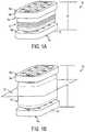
- FIG. 2Ais a perspective view of a free-standing pleated member for use with a self-distracting spinal implant
- FIG. 2Bis a front view of the pleated member of FIG. 2A in the compressed condition, showing an inlet port;
- FIG. 2Cis a front view of the pleated member of FIG. 2A , in the expanded condition
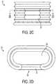
- FIG. 2Dis a top sectional view of the pleated member of FIG. 2A , showing an interior volume;
- FIG. 3Ais a perspective view of a hard-walled, self-distracting spinal implant in a piston configuration, in the compressed condition;
- FIG. 3Bis a perspective view of the implant of FIG. 3A in the expanded condition
- FIG. 3Cis a perspective view of the implant of FIG. 3A , showing a hydraulic tool attached;
- FIG. 3Dis a perspective view of an implant of the type shown in FIG. 3A in an alternate, round shape showing a hydraulic tool attached;
- FIG. 4Ais a perspective view of a self-distracting spinal implant in a piston configuration with a pleated member.
- FIG. 4Bis a top view of the implant of FIG. 4A ;
- FIG. 5Ais a front view of a self-distracting spinal implant in a piston configuration with articulating joints
- FIG. 5Bis a front view of the implant of FIG. 5A showing one end plate oriented at an angle;
- FIG. 6Ais a representation of a self-distracting spinal implant before it is compressed for insertion into an intervertebral disc space;
- FIG. 6Bis a representation of the implant of FIG. 6A in the compressed condition for insertion in the intervertebral disc space;
- FIG. 6Cis a representation of the implant of FIG. 6A in the expanded condition after it is inserted into the intervertebral disc space;
- FIG. 7Ais a representation of a system for inserting a self-distracting spinal implant into an intervertebral disc space
- FIG. 7Bis a representation of the system of FIG. 7A .
- the presently disclosed embodimentsrelate to methods for simultaneously distracting two adjacent vertebral bodies and to spinal implants configured for self-distraction of the intervertebral disc space.
- the self-distracting spinal implants disclosed hereinare incrementally adjustable for height and for lordotic angle.
- the implantis of an optimal shape for placement within the intervertebral disc space and is configured to replicate and restore a natural angle between two adjacent vertebrae.
- the implantis configured to contain a bone packing material to encourage bony ingrowth between two adjacent vertebrae.
- a spinal implanthaving an expandable container with an interior volume that is selectively expandable between a compressed condition and an expanded condition.
- the expandable containeris disposed between a superior endplate member having a bone-contacting surface and an engagement surface effective to mate with a superior surface of the expandable container and an inferior endplate member having a bone-contacting surface and an engagement surface effective to mate with an inferior surface of the expandable container.
- the engagement surface of the superior endplate and the engagement surface of the inferior endplatecan be planar engagement surfaces.
- at least one inlet portis formed in the expandable container and is effective to communicate a fluid to at least one cavity disposed within the interior volume of the expandable container.
- FIGS. 1A and 1Billustrate one embodiment of a self-distracting implant 10 having a pleated member 12 , such as an articulating bellows, disposed between a superior endplate member 14 a and an inferior endplate member 14 b .
- the implant 10can have a variety of shapes and sizes, but in one embodiment, the implant 10 can be elliptically shaped and it has a distraction envelope in the range of about 5 mm to 15 mm.
- FIG. 1Ashows the implant 10 in a compressed condition, in which a height H 1 is at a minimum of the compression envelope, e.g., about 5 mm.
- FIG. 1Bshows the implant 10 in an expanded condition, in which a height H 2 is at a maximum envelope, e.g., about 15 mm.
- the superior endplate member 14 aincludes a superior bone-contacting surface 16 a and an inferior engagement surface 18 a that is configured to mate with a superior surface of the pleated member 12 .
- the inferior endplate member 14 blikewise includes an inferior bone-contacting surface 16 b and a superior engagement surface 18 b that is configured to mate with an inferior surface of the pleated member 12 .
- the endplate members 14 a , 14 bare substantially rigid and can be formed from a variety of known biocompatible materials, including carbon fiber reinforced polymer (CFRP), metal, and any metal alloys.
- the superior and inferior bone-contacting surfaces 16 a , 16 bare configured to seat and retain a formable component (not shown) that can conform to the natural contours of the adjacent vertebra to enhance the fit within the intervertebral disc space.
- a formable componentnot shown
- any appropriate biocompatible formable component known in the artcan be used to improve the conformance of the superior and inferior endplate members 14 a , 14 b .
- Suitable examplesinclude high-durometer silicones and polyurethanes, in-situ curing resins such as polymethylmethacrylate (PMMA) (e.g., SmartSet GMVTM by DePuy Orthopedics of Warsaw, Ind.) and tetraethyleneglycol dimethacrylate (TEGDMA) (e.g., NRCTM by Dentsply of York, Pa.), curing/setting calcium phosphate cements (e.g., NanOssTM Bone Void Filler by Angstrom Medica of Woburn, Mass.), polyanhydrides, polyvinyl acetates, and polysaccharides (e.g., EurekaTM DUET by SurModics of Eden Prairie, Minn.).
- PMMApolymethylmethacrylate
- TEGDMAtetraethyleneglycol dimethacrylate
- NRCTMtetraethyleneglycol dimethacrylate
- curing/setting calcium phosphate cementse.
- the superior and inferior endplate members 14 a , 14 bcan be parallel to one another and to a horizontal plane 26 extending through the implant. Because the endplate members 14 a , 14 b are attached to the pleated member 12 , however, their angle with respect to each other and with respect to the horizontal plane 26 can be adjusted. As the implant 10 is expanded, the endplate members 14 a , 14 b are free to rotate with respect to the horizontal plane 26 as necessary to compensate for any height differences in the implant 10 and any necessary lordotic angle within the intervertebral disc space.
- the pleated member 12 coupled with the endplate members 14 a , 14 bcan allow for a lordotic angle of any where between zero and at least sixteen degrees with respect to the horizontal plane 26 extending therethrough. This allows the endplate members 14 a , 14 b to better conform to any necessary or natural lordotic angle between two adjacent vertebrae.
- FIGS. 2A-2Dillustrate one example of a pleated member 12 that can be used to form the implant 10 of the type described above.
- the pleated member 12is expandable and compressible as needed, having relatively thin walls with a flexible bellows-like structure.
- the pleated member 12can be formed from any suitable material known in the art. Some examples of suitable materials include elastomeric materials, polymeric materials, metals, and metal alloys.
- an interior volume 23can be disposed within the pleated member 12 and is configured for receiving a compressible and curable expansion material which enables the pleated member 12 to be expanded as needed.
- an inner annular opening 20 of the pleated member 12can contain an expandable balloon (not shown), also configured for receiving an expansion material. Any suitable compressible and curable expansion material known in the art can be used to fill the interior volume 23 or the expandable balloon.
- suitable materialsinclude polymethyl methacrylate (PMMA), synthetic cortical bone fillers such as setting/curing calcium phosphate cement (e.g., CortossTM), tetraethyleneglycol dimethacrylate (Bis-Teg DMA), polyurethane, cyanoacrylate, etc.
- PMMApolymethyl methacrylate
- synthetic cortical bone fillerssuch as setting/curing calcium phosphate cement (e.g., CortossTM), tetraethyleneglycol dimethacrylate (Bis-Teg DMA), polyurethane, cyanoacrylate, etc.
- any biocompatible, expandable balloon known in the artcan be used within the inner annular opening 20 of the pleated member 12 .
- the interior volume 23 within the pleated member 12can contain more than one cavity or chamber suitable for an expansion material, or alternatively, for multiple expandable balloons. Having more than one chamber within the interior volume 23 will allow for greater flexibility in height and angle customization. For example, one chamber can be filled to a greater extent than another chamber, thereby causing one part of the pleated member 12 to expand to a height greater than another part of the pleated member 12 . In addition, one chamber can contain an expandable balloon which is expanded to a greater extent than an expandable balloon within a second chamber. This would allow the implant 10 to be appropriately configured for a more natural lordotic angle within the intervertebral disc space. A person skilled in the art will appreciate that any number of chambers and/or expandable balloons can be used with the pleated member 12 so that the height and angle of the implant 10 is completely customizable.
- FIGS. 2B-2Dalso illustrate an inlet port 22 formed in the pleated member 12 which is effective to communicate a fluid to the interior volume 23 of the pleated member 12 .
- a filler devicecan be attached to and detached from the inlet port 22 via a snap off connector, a natural hinge, a luer connector, a notch sensitive device, or any other connection mechanism known in the art.
- the mouth or inlet of the ballooncan be congruent with the inlet port 22 so that a filler device attached to the inlet port 22 is effective to fill the expandable balloon.
- the filler devicecan enter through the inlet port 22 and attach directly to the balloon within the interior volume 23 of the implant for filling purposes.
- any filler device known in the artcan be used to fill the interior volume 23 and/or expandable balloon with a curable expansion material.
- inlet port 22is shown to be disposed within a side of the pleated member 12 , one skilled in the art will appreciate that it can alternatively be disposed within the superior or inferior endplate members 14 a , 14 b.
- flow restrictorscan be used between the chambers to allow different quantities of material to be injected into different areas of the implant. Additionally or alternatively, the flow rate restrictors can allow material to be injected at different flow rates. Such a design facilitates customization of height and lordotic angle.
- multiple inlet ports disposed within the sides of the pleated member 12 and/or the endplate members 14 a , 14 bcan be used to fill independent multiple chambers or multiple expandable balloons.
- FIGS. 3A and 3Bshow one exemplary embodiment of an elliptical or cashew-shaped, hard-walled implant 100 having a fixed platen member 102 and a movable platen member 104 in a piston-like configuration. At least a portion of the movable platen member 104 is disposed within the fixed platen member 102 and the two are slidingly engaged with one another in a fluid tight seal.
- a superior endplate member 106 aincludes a superior bone-contacting surface 108 a and an inferior engagement surface 110 a that is configured to mate with a superior surface of the movable platen member 104 .
- An inferior endplate member 106 bincludes an inferior bone-contacting surface 108 b and a superior engagement surface 110 b that is configured to mate with an inferior surface of the fixed platen member 102 . As shown an inner annular opening 120 may extend through the device.
- FIG. 3Cshows the implant 100 in a compressed condition, with an inlet port 112 disposed in a side of the fixed platen member 102 . The inlet port 112 is in fluid communication with an interior volume 123 ′ ( FIG. 3D ) that is configured for receiving a hydraulic fluid, which can be delivered through any suitable filler device, such as a hydraulic feed 114 .
- FIG. 3Dshows a similarly constructed implant 100 ′ in a piston-like configuration, as described above, having a circular configuration.
- An inlet port 112 ′ located in the fixed platen member 102 ′is provided, and is configured to receive a hydraulic feed 114 ′.
- the inlet port 112 ′is in fluid communication with an interior volume 123 ′ and is configured to receive a hydraulic fluid, which can be a curable material.
- FIG. 3Dalso illustrates that the superior and inferior bone-contacting surfaces 116 a , 116 b of the implant 100 ′ include a roughened surface. The roughened surface allows the implant 100 ′ to have a more stable fit within the intervertebral disc space by providing increased friction between the vertebral endplates and the implant 100 ′.
- any of the implant embodiments disclosed hereincan include bone-contacting surfaces formed from any roughened surface known in the art.
- a person skilled in the artwill also appreciate that any of the embodiments disclosed herein can be formed of any geometrical shape.
- the hydraulic feed 114 , 114 ′is configured to communicate a fluid to the interior volume 123 ′ of the piston and thereby cause the movable platen member 104 , 104 ′ to move relative to the fixed platen member 102 , 102 ′ to expand and increase the height of the implant 100 , 100 ′.
- an inlet port capable of receiving a hydraulic feedcan also be formed in either of the superior and inferior endplate members.
- FIGS. 4A and 4Bshow a further embodiment of a self-distracting spinal implant 200 having an elliptical or cashew-shape and including a fixed platen member 202 and a movable platen member 204 . At least a portion of the movable platen member 204 is disposed within the fixed platen member 202 in a piston-like configuration with a fluid tight seal therebetween.
- a pleated member 206is contained in a bore 214 formed within the movable platen member 204 such that it extends between a superior endplate member 208 a and an inferior endplate member 208 b .
- the pleated member 206is configured to receive a hydraulic fluid (e.g., a curable material) for moving the piston.
- a hydraulic fluide.g., a curable material
- the pleated member 206provides more flexibility in the tolerance required for this fluid tight seal than if the fixed platen member 202 were mated directly to the movable platen member 204 without the pleated member 206 .
- the superior and inferior endplate members 208 a , 208 bare otherwise coupled to the movable platen member 204 and the fixed platen member 202 , respectively, by biocompatible screws 212 .
- the screws 212can be inserted into the superior and inferior endplate members 208 a , 208 b through a superior bone-contacting surface 222 a and an inferior bone-contacting surface 222 b .
- a person skilled in the artwill appreciate that any appropriate method of attaching the superior and inferior endplate members 208 a , 208 b to the movable platen member 204 and the fixed platen member 202 can be used.
- an inlet port 216is disposed in the fixed platen member 202 of the implant 200 and is in fluid communication with an interior volume 223 of the piston, which is configured for receiving hydraulic fluid. Fluid is injected into the implant 200 via the inlet port 216 and a hydraulic feed 218 to cause the movable platen member 204 and the pleated member 206 to move relative to the fixed platen member 202 to expand and increase the height of the implant 200 .
- FIG. 4Ashows the implant 200 in an expanded condition.
- FIGS. 5A and 5Bshow another exemplary embodiment of a self-distracting spinal implant 300 having two piston members and two articulating joints.
- a first piston memberincludes a fixed platen member 302 and a superior movable platen member 304 a disposed within a superior portion of the fixed platen member 302 in a piston-like configuration with a fluid tight seal.
- a second piston memberlikewise includes the fixed platen member 302 , as well as an inferior movable platen member 304 b disposed within an inferior portion of the fixed platen member 302 in a piston-like configuration with a fluid tight seal.
- the superior movable platen member 304 ais connected to a superior endplate member 306 a via an articulating joint 308 , such as a ball joint, that enables angulation of the superior endplate member 306 a .
- the inferior movable platen member 304 bis likewise connected to an inferior endplate member 306 b via an articulating member 308 .
- the superior and/or inferior endplate members 306 a , 306 bcan rotate via the articulating joint 308 relative to a horizontal plane 312 extending therethrough, as illustrated in FIG. 5B . This allows the implant 300 to conform to any necessary and/or natural lordotic angle within the intervertebral disc space.
- an inlet portcan be formed in the fixed platen member 302 of the implant 300 , as well as in any other portion of the implant 300 .
- the inlet portcan be configured to receive a hydraulic feed capable of communicating hydraulic fluid to an interior volume 310 of the implant.
- the hydraulic fluidis effective to move the superior and inferior movable platen members 304 a , 304 b relative to the fixed platen member 302 , thereby expanding and retracting the implant 300 as necessary.
- the implant 500can be inserted into the intervertebral disc space 502 via an access port or cannula that extends through a patient's skin to a site where the implant is to be implanted. As shown in FIG. 6B , the implant 500 will initially be in a compressed condition with a minimal height, for example, of about 5 mm.
- the implant 500can be expanded to distract two adjacent vertebrae 504 , 506 by an appropriate amount up to the implant's maximum height, for example, of about 15 mm. After distraction, any necessary angular adjustments can be made so that the implant 500 conforms to the natural lordotic angle and spacing between the adjacent vertebrae 504 , 506 , as shown in FIG. 6C .
- the implant 10can be inserted through a cannula or port and into a disc space in a compressed condition with a minimum height of about 5 mm.
- a compressible and curable expansion materialsuch as PMMA, synthetic cortical bone fillers, such as calcium phosphate cement (e.g., CortossTM), tetraethyleneglycol dimethacrylate (Bis-Teg DMA), polyurethane, cyanoacrylate, polysaccharides, polyanhydride, in situ curing silicone, etc., is then injected into the interior volume, multiple chambers, or expandable balloon of the pleated member 12 by a filler device.
- synthetic cortical bone fillerssuch as calcium phosphate cement (e.g., CortossTM), tetraethyleneglycol dimethacrylate (Bis-Teg DMA), polyurethane, cyanoacrylate, polysaccharides, polyanhydride, in situ curing silicone, etc.
- the superior and inferior endplate members 14 a , 14 bmove apart upon expansion of the pleated member 12 so that they contact and apply a distraction force to the two adjacent vertebrae, causing them to distract.
- the filler materialis injected into the interior volume until the vertebrae are at a desired separation.
- the pleated member 12allows the implant 10 to conform to a natural lordotic angle as it expands. After the necessary height and angle are achieved, the material can be quickly cured by light or chemical so that the material forms a solid plug within the implant 10 , thereby retaining the customized height and lordotic angle.
- any biocompatible, compressible, and curable material known in the artcan be injected into the implant 10 to distract the vertebrae.
- the implant 10can be expanded to any height within its distraction envelope of between about 5 mm and 15 mm.
- the implant 100 , 200is inserted into a disc space in a compressed condition with a minimum height of about 5 mm.
- a hydraulic fluid(which can be curable) is then injected into the interior volume 123 ′, 223 of the piston via the hydraulic feed.
- the movable platen member 104 , 204moves relative to the fixed platen member 102 , 202 to cause the implant 100 , 200 to expand.
- the superior and inferior bone-contacting surfacesexert a pressure on the adjacent vertebrae, causing them to distract.
- the surgeoncan thereby adjust the spacing between the adjacent vertebrae by adjusting the height of the implant 100 , 200 up to its maximum height of about 15 mm.
- the hydraulic feedcan be removed (and cured in the case of a curable material), and the implant 100 , 200 will remain at the desired height, providing support and stabilization between the vertebrae.
- the implant 300is inserted within a disc space in a compressed condition with a minimum height of about 5 mm.
- a hydraulic fluid(which can be curable) is then injected into the interior volume 310 of the piston via the hydraulic feed.
- the superior and inferior movable platen members 304 a , 304 bmove relative to the fixed platen member 302 to cause the implant 300 to expand.
- the superior and inferior bone-contacting surfacesthus exert a pressure on the adjacent vertebrae, causing them to distract as the implant 300 is expanded.
- the surgeoncan thereby adjust the spacing between the adjacent vertebrae by adjusting the height of the implant 300 up to its maximum height of about 15 mm.
- the surgeoncan make angular adjustments to the superior and/or inferior endplate members 306 a , 306 b via the articulating joints 308 relative to the horizontal plane 312 so that the implant 300 better conforms to the necessary and/or natural lordotic angle between the adjacent vertebra.
- the hydraulic feedcan be removed (and cured in the case of a curable material), and the implant 300 will remain at the desired height and angle, providing support and stabilization between the vertebrae.
- each piston membercan be independently adjusted to achieve different heights, which allows the implant to conform to any necessary or natural lordotic angle of the disc space.
- the pleated membersare configured for receiving a hydraulic fluid and provide flexibility in the tolerance required for the fluid tight seal that exists between a movable platen member of each of the multiple pistons and a superior endplate member.
- a hydraulic feedcan be used to activate the pistons and can be removed once the required height and angle of the implant has been achieved.
- a systemis pre-assembled to include a self-distracting spinal implant 600 attached to an insertion tool, such as a cannula 602 .
- a liquid feed device 604is in fluid communication with the cannula 602 to inject a curable expansion material into the implant 600 .
- a fluid control valve 606is disposed on a proximal end of the liquid feed device 604 so that the flow of the curable expansion material can be controlled.
- a fiber optic cable 608is disposed within the cannula 602 and its distal end extends into an inlet port of the implant 600 to facilitate curing of the injected material.
- the fiber optic cable 608can be attached at its proximal end to any suitable source of curing energy, such as a high intensity light-emitting diode (LED) disposed within a housing 610 as shown in FIG. 7B .
- LEDhigh intensity light-emitting diode
- the implant 600is attached to a distal end of the cannula 602 and is initially in a compressed condition with a height, for example, of about 5 mm.
- the implant 600is inserted through a minimally invasive surgery access port 612 that extends through a patient's skin to a site where the implant is to be implanted, and which can be located adjacent to the relevant vertebral bodies 614 , 614 ′.
- the implant 600is maneuvered into the intervertebral disc space with the cannula 602 .
- the fluid control valve 606is opened to allow a curable expansion material to flow through the cannula 602 and into the interior volume of the implant 600 .
- the implant 600expands and causes the distraction of the adjacent vertebrae 614 , 614 ′ to any height up to the implant's maximum height of about 15 mm.
- a surgeoncan then make any necessary adjustments to the distraction space and the relative force of the implant 600 on the vertebrae 614 , 614 ′.
- angular adjustmentscan be made to the implant 600 to compensate for any required lordotic angle between the vertebrae 614 , 614 ′.
- the curing energycan be activated to essentially instantaneously cure the material within the implant 600 , forming a solid plug that will retain the height and angular requirements of the disc space.
- the cannula 602can then be removed from the implant 600 , for example, by breaking or snapping a notch attachment.
- the cannula 602can be joined to and detached from the implant 600 by any method known in the art.
- the implant 600can be expanded to and kept at any height within its distraction envelope of between about 5 mm and 15 mm.
- the self-distracting spinal implants disclosed hereinare particularly well suited for minimally invasive surgery. That is, the self-distracting implants disclosed herein have a compressed envelope with a height of about 5 mm and can easily be inserted via a minimally invasive surgery port, without the need of an open surgical procedure.
- Such procedureswhich are generally well known to those skilled in the art, tend to result in less operative trauma for the patient than more invasive procedures.
- Minimally invasive proceduresalso tend to be less expensive, reduce hospitalization time, cause less pain and scarring, speed recovery, and reduce the incidence of post-surgical complications, such as adhesions.
- the self-distracting spinal implants described hereincan be adapted so as to allow for spinal fusion and/or spinal fixation.
- Any of the implant designs disclosed hereincan include or be formed of a fusion-promoting bioactive material so that the implant actively participates in spinal fusion.
- the implantis made from a bioactive material.
- a bioactive materialcan be formed as a coating on a non-bioactive material from which the implant is formed.
- the implantcan be filled with a bioactive material so that bony ingrowth through the implant and between the vertebra is allowed and encouraged.
- the implantcan be formed of a metal or CFRP and be coated or filled with a fusion-promoting bioactive material.
- Exemplary fusion promoting bioactive materialscan include allograft bone, tricalcium phosphates (TCP), hydroxyapatite, Biocryl RapidTM (tricalcium phosphate loaded poly-L-lactic acid/Poly-glycolic acid), bioglass, plasma sprayed titanium, hydroxyapatite-coated titanium, surface textured titanium, and polymer composites.
- TCPtricalcium phosphates
- hydroxyapatitehydroxyapatite
- Biocryl RapidTMtricalcium phosphate loaded poly-L-lactic acid/Poly-glycolic acid
Landscapes
- Health & Medical Sciences (AREA)
- Engineering & Computer Science (AREA)
- Biomedical Technology (AREA)
- Orthopedic Medicine & Surgery (AREA)
- Neurology (AREA)
- Transplantation (AREA)
- Heart & Thoracic Surgery (AREA)
- Oral & Maxillofacial Surgery (AREA)
- Cardiology (AREA)
- Vascular Medicine (AREA)
- Life Sciences & Earth Sciences (AREA)
- Animal Behavior & Ethology (AREA)
- General Health & Medical Sciences (AREA)
- Public Health (AREA)
- Veterinary Medicine (AREA)
- Chemical & Material Sciences (AREA)
- Dispersion Chemistry (AREA)
- Physical Education & Sports Medicine (AREA)
- Prostheses (AREA)
Abstract
Description
Claims (18)
Priority Applications (2)
| Application Number | Priority Date | Filing Date | Title |
|---|---|---|---|
| US14/792,871US10537435B2 (en) | 2007-05-17 | 2015-07-07 | Self-distracting cage |
| US16/736,403US11432939B2 (en) | 2007-05-17 | 2020-01-07 | Self-distracting cage |
Applications Claiming Priority (3)
| Application Number | Priority Date | Filing Date | Title |
|---|---|---|---|
| US11/750,113US8273124B2 (en) | 2007-05-17 | 2007-05-17 | Self-distracting cage |
| US13/561,271US9101486B2 (en) | 2007-05-17 | 2012-07-30 | Self-distracting cage |
| US14/792,871US10537435B2 (en) | 2007-05-17 | 2015-07-07 | Self-distracting cage |
Related Parent Applications (1)
| Application Number | Title | Priority Date | Filing Date |
|---|---|---|---|
| US13/561,271ContinuationUS9101486B2 (en) | 2007-05-17 | 2012-07-30 | Self-distracting cage |
Related Child Applications (1)
| Application Number | Title | Priority Date | Filing Date |
|---|---|---|---|
| US16/736,403ContinuationUS11432939B2 (en) | 2007-05-17 | 2020-01-07 | Self-distracting cage |
Publications (2)
| Publication Number | Publication Date |
|---|---|
| US20150305888A1 US20150305888A1 (en) | 2015-10-29 |
| US10537435B2true US10537435B2 (en) | 2020-01-21 |
Family
ID=40028346
Family Applications (4)
| Application Number | Title | Priority Date | Filing Date |
|---|---|---|---|
| US11/750,113Active2030-07-26US8273124B2 (en) | 2007-05-17 | 2007-05-17 | Self-distracting cage |
| US13/561,271Expired - Fee RelatedUS9101486B2 (en) | 2007-05-17 | 2012-07-30 | Self-distracting cage |
| US14/792,871Expired - Fee RelatedUS10537435B2 (en) | 2007-05-17 | 2015-07-07 | Self-distracting cage |
| US16/736,403Active2028-07-11US11432939B2 (en) | 2007-05-17 | 2020-01-07 | Self-distracting cage |
Family Applications Before (2)
| Application Number | Title | Priority Date | Filing Date |
|---|---|---|---|
| US11/750,113Active2030-07-26US8273124B2 (en) | 2007-05-17 | 2007-05-17 | Self-distracting cage |
| US13/561,271Expired - Fee RelatedUS9101486B2 (en) | 2007-05-17 | 2012-07-30 | Self-distracting cage |
Family Applications After (1)
| Application Number | Title | Priority Date | Filing Date |
|---|---|---|---|
| US16/736,403Active2028-07-11US11432939B2 (en) | 2007-05-17 | 2020-01-07 | Self-distracting cage |
Country Status (2)
| Country | Link |
|---|---|
| US (4) | US8273124B2 (en) |
| WO (1) | WO2008144175A1 (en) |
Cited By (1)
| Publication number | Priority date | Publication date | Assignee | Title |
|---|---|---|---|---|
| US11432939B2 (en) | 2007-05-17 | 2022-09-06 | DePuy Synthes Products, Inc. | Self-distracting cage |
Families Citing this family (213)
| Publication number | Priority date | Publication date | Assignee | Title |
|---|---|---|---|---|
| FR2858546B1 (en) | 2003-08-04 | 2006-04-28 | Spine Next Sa | INTERVERTEBRAL DISC PROSTHESIS |
| EP1639968A1 (en)* | 2004-09-23 | 2006-03-29 | Cervitech, Inc. | Implant with a part to be inserted and anchored in a bone cavity |
| US8597360B2 (en) | 2004-11-03 | 2013-12-03 | Neuropro Technologies, Inc. | Bone fusion device |
| WO2006058221A2 (en) | 2004-11-24 | 2006-06-01 | Abdou Samy M | Devices and methods for inter-vertebral orthopedic device placement |
| US7955339B2 (en)* | 2005-05-24 | 2011-06-07 | Kyphon Sarl | Low-compliance expandable medical device |
| US9028550B2 (en) | 2005-09-26 | 2015-05-12 | Coalign Innovations, Inc. | Selectively expanding spine cage with enhanced bone graft infusion |
| US7806900B2 (en) | 2006-04-26 | 2010-10-05 | Illuminoss Medical, Inc. | Apparatus and methods for delivery of reinforcing materials to bone |
| US7731752B2 (en)* | 2006-07-21 | 2010-06-08 | Warsaw Orthopedic, Inc. | Implant with nested members and methods of use |
| WO2008021972A2 (en)* | 2006-08-10 | 2008-02-21 | Pioneer Surgical Technology, Inc. | Intervertebral disc space sizing tools and methods |
| US7879041B2 (en) | 2006-11-10 | 2011-02-01 | Illuminoss Medical, Inc. | Systems and methods for internal bone fixation |
| CA2669129C (en) | 2006-11-10 | 2014-09-16 | Illuminoss Medical, Inc. | Systems and methods for internal bone fixation |
| FI122996B (en)* | 2007-05-10 | 2012-09-28 | Teliasonera Ab | Processing of service request |
| US20100204794A1 (en)* | 2007-06-06 | 2010-08-12 | Peter Jarzem | Prosthetic vertebral body |
| US8328818B1 (en) | 2007-08-31 | 2012-12-11 | Globus Medical, Inc. | Devices and methods for treating bone |
| US8142441B2 (en)* | 2008-10-16 | 2012-03-27 | Aesculap Implant Systems, Llc | Surgical instrument and method of use for inserting an implant between two bones |
| US8591587B2 (en) | 2007-10-30 | 2013-11-26 | Aesculap Implant Systems, Llc | Vertebral body replacement device and method for use to maintain a space between two vertebral bodies within a spine |
| US8182537B2 (en) | 2007-10-30 | 2012-05-22 | Aesculap Implant Systems, Llc | Vertebral body replacement device and method for use to maintain a space between two vertebral bodies within a spine |
| US9427289B2 (en) | 2007-10-31 | 2016-08-30 | Illuminoss Medical, Inc. | Light source |
| US8403968B2 (en) | 2007-12-26 | 2013-03-26 | Illuminoss Medical, Inc. | Apparatus and methods for repairing craniomaxillofacial bones using customized bone plates |
| US8932355B2 (en) | 2008-02-22 | 2015-01-13 | Coalign Innovations, Inc. | Spinal implant with expandable fixation |
| US8992620B2 (en) | 2008-12-10 | 2015-03-31 | Coalign Innovations, Inc. | Adjustable distraction cage with linked locking mechanisms |
| US20100145455A1 (en) | 2008-12-10 | 2010-06-10 | Innvotec Surgical, Inc. | Lockable spinal implant |
| US12232975B2 (en) | 2008-02-22 | 2025-02-25 | Howmedica Osteonics Corp. | Lockable spinal implant |
| US8267939B2 (en) | 2008-02-28 | 2012-09-18 | Stryker Spine | Tool for implanting expandable intervertebral implant |
| US20090240334A1 (en)* | 2008-03-19 | 2009-09-24 | Richelsoph Marc E | Vertebral device for restoration of vertebral body height |
| US8377135B1 (en)* | 2008-03-31 | 2013-02-19 | Nuvasive, Inc. | Textile-based surgical implant and related methods |
| US8545566B2 (en)* | 2008-10-13 | 2013-10-01 | Globus Medical, Inc. | Articulating spacer |
| BRPI0923322A2 (en)* | 2008-12-22 | 2016-01-12 | Synthes Gmbh | expandable vertebral body replacement method and device. |
| BRPI0921108A2 (en)* | 2008-12-22 | 2016-02-16 | Synthes Gmbh | expandable vertebral body replacement method and system |
| US8142435B2 (en) | 2009-02-19 | 2012-03-27 | Aesculap Implant Systems, Llc | Multi-functional surgical instrument and method of use for inserting an implant between two bones |
| US20100241231A1 (en)* | 2009-02-20 | 2010-09-23 | Marino James F | Intervertebral fixation device |
| US8123808B2 (en) | 2009-04-16 | 2012-02-28 | Warsaw Orthopedic, Inc. | Vertebral endplate connection implant and method |
| US20100268341A1 (en)* | 2009-04-16 | 2010-10-21 | WARSAW ORTHOPEDIC, INC., An Indian Corporation | Minimally invasive expandable vertebral implant and method |
| US8123809B2 (en) | 2009-04-16 | 2012-02-28 | Warsaw Orthopedic, Inc. | Deployment system and method for an expandable vertebral implant |
| US8105360B1 (en) | 2009-07-16 | 2012-01-31 | Orthonex LLC | Device for dynamic stabilization of the spine |
| EP2467098A4 (en) | 2009-08-19 | 2015-07-08 | Illuminoss Medical Inc | Devices and methods for bone alignment, stabilization and distraction |
| US8480748B2 (en)* | 2010-10-07 | 2013-07-09 | Nicholas Poulos | Lordotic expandable interbody implant and method |
| US10098758B2 (en) | 2009-10-15 | 2018-10-16 | Globus Medical, Inc. | Expandable fusion device and method of installation thereof |
| US11103366B2 (en) | 2009-10-15 | 2021-08-31 | Globus Medical, Inc. | Expandable fusion device and method of installation thereof |
| US8679183B2 (en) | 2010-06-25 | 2014-03-25 | Globus Medical | Expandable fusion device and method of installation thereof |
| US10806596B2 (en) | 2009-10-15 | 2020-10-20 | Globus Medical, Inc. | Expandable fusion device and method installation thereof |
| US8062375B2 (en) | 2009-10-15 | 2011-11-22 | Globus Medical, Inc. | Expandable fusion device and method of installation thereof |
| US8685098B2 (en) | 2010-06-25 | 2014-04-01 | Globus Medical, Inc. | Expandable fusion device and method of installation thereof |
| US8709086B2 (en) | 2009-10-15 | 2014-04-29 | Globus Medical, Inc. | Expandable fusion device and method of installation thereof |
| US11344430B2 (en) | 2009-10-15 | 2022-05-31 | Globus Medical, Inc. | Expandable fusion device and method of installation thereof |
| US11564807B2 (en) | 2009-10-15 | 2023-01-31 | Globus Medical, Inc. | Expandable fusion device and method of installation thereof |
| US8556979B2 (en) | 2009-10-15 | 2013-10-15 | Globus Medical, Inc. | Expandable fusion device and method of installation thereof |
| US10327917B2 (en) | 2009-10-15 | 2019-06-25 | Globus Medical, Inc. | Expandable fusion device and method of installation thereof |
| US9216095B2 (en) | 2009-10-15 | 2015-12-22 | Globus Medical, Inc. | Expandable fusion device and method of installation thereof |
| US9155628B2 (en) | 2009-10-15 | 2015-10-13 | Globus Medical, Inc. | Expandable fusion device and method of installation thereof |
| US8764806B2 (en) | 2009-12-07 | 2014-07-01 | Samy Abdou | Devices and methods for minimally invasive spinal stabilization and instrumentation |
| US8353963B2 (en) | 2010-01-12 | 2013-01-15 | Globus Medical | Expandable spacer and method for use thereof |
| US9913726B2 (en) | 2010-02-24 | 2018-03-13 | Globus Medical, Inc. | Expandable intervertebral spacer and method of posterior insertion thereof |
| EP2547292B1 (en) | 2010-03-16 | 2019-04-24 | Pinnacle Spine Group, LLC | Ntervertebral implants and graft delivery systems |
| US8870880B2 (en) | 2010-04-12 | 2014-10-28 | Globus Medical, Inc. | Angling inserter tool for expandable vertebral implant |
| US9301850B2 (en) | 2010-04-12 | 2016-04-05 | Globus Medical, Inc. | Expandable vertebral implant |
| US8353957B2 (en) | 2010-04-20 | 2013-01-15 | Warsaw Orthopedic, Inc. | Expandable medical device and method |
| US8673007B2 (en) | 2010-04-20 | 2014-03-18 | Warsaw Orthopedic, Inc. | Implant with insertion device and method |
| US9597200B2 (en) | 2010-06-25 | 2017-03-21 | Globus Medical, Inc | Expandable fusion device and method of installation thereof |
| ES2541764T3 (en)* | 2010-08-09 | 2015-07-24 | Christian Röbling | Vertebral body prosthesis |
| US10869768B2 (en) | 2010-09-03 | 2020-12-22 | Globus Medical Inc. | Expandable fusion device and method of installation thereof |
| US10709573B2 (en) | 2010-09-03 | 2020-07-14 | Globus Medical Inc. | Expandable fusion device and method of installation thereof |
| US10085849B2 (en) | 2010-09-03 | 2018-10-02 | Globus Medical, Inc. | Expandable fusion device and method of installation thereof |
| US11793654B2 (en) | 2010-09-03 | 2023-10-24 | Globus Medical, Inc. | Expandable fusion device and method of installation thereof |
| US12370057B2 (en) | 2010-09-03 | 2025-07-29 | Globus Medical, Inc. | Expandable fusion device and method of installation thereof |
| US10945858B2 (en) | 2010-09-03 | 2021-03-16 | Globus Medical, Inc. | Expandable interspinous process fixation device |
| US8435298B2 (en) | 2010-09-03 | 2013-05-07 | Globus Medical, Inc. | Expandable fusion device and method of installation thereof |
| US12059358B2 (en) | 2010-09-03 | 2024-08-13 | Globus Medical Inc. | Expandable fusion device and method of installation thereof |
| US10512550B2 (en) | 2010-09-03 | 2019-12-24 | Globus Medical, Inc. | Expandable interspinous process fixation device |
| US9907673B2 (en) | 2010-09-03 | 2018-03-06 | Globus Medical, Inc. | Expandable fusion device and method of installation thereof |
| US8491659B2 (en) | 2010-09-03 | 2013-07-23 | Globus Medical, Inc. | Expandable fusion device and method of installation thereof |
| US10842644B2 (en) | 2010-09-03 | 2020-11-24 | Globus Medical, Inc. | Expandable fusion device and method of installation thereof |
| US8845734B2 (en) | 2010-09-03 | 2014-09-30 | Globus Medical, Inc. | Expandable fusion device and method of installation thereof |
| US9855151B2 (en) | 2010-09-03 | 2018-01-02 | Globus Medical, Inc | Expandable fusion device and method of installation thereof |
| US8852279B2 (en) | 2010-09-03 | 2014-10-07 | Globus Medical, Inc. | Expandable fusion device and method of installation thereof |
| US8845731B2 (en) | 2010-09-03 | 2014-09-30 | Globus Medical, Inc. | Expandable fusion device and method of installation thereof |
| US8845732B2 (en) | 2010-09-03 | 2014-09-30 | Globus Medical, Inc. | Expandable fusion device and method of installation thereof |
| US9351848B2 (en) | 2010-09-03 | 2016-05-31 | Globus Medical, Inc. | Expandable fusion device and method of installation thereof |
| US10758367B2 (en) | 2010-09-03 | 2020-09-01 | Globus Medical Inc. | Expandable fusion device and method of installation thereof |
| US11446162B2 (en) | 2010-09-03 | 2022-09-20 | Globus Medical, Inc. | Expandable fusion device and method of installation thereof |
| US9474625B2 (en) | 2010-09-03 | 2016-10-25 | Globus Medical, Inc | Expandable fusion device and method of installation thereof |
| US10835387B2 (en) | 2010-09-03 | 2020-11-17 | Globus Medical Inc. | Expandable fusion device and method of installation thereof |
| US10779957B2 (en) | 2010-09-03 | 2020-09-22 | Globus Medical, Inc. | Expandable fusion device and method of installation thereof |
| US9566168B2 (en) | 2010-09-03 | 2017-02-14 | Globus Medical, Inc. | Expandable fusion device and method of installation thereof |
| US8632595B2 (en) | 2010-09-03 | 2014-01-21 | Globus Medical, Inc. | Expandable fusion device and method of installation thereof |
| US8425611B2 (en)* | 2010-10-26 | 2013-04-23 | Warsaw Orthopedic, Inc. | Expandable orthopedic implant system and method |
| US20120109304A1 (en)* | 2010-10-29 | 2012-05-03 | Warsaw Orthopedic, Inc. | Medical implant and method for photodynamic therapy |
| US8721566B2 (en) | 2010-11-12 | 2014-05-13 | Robert A. Connor | Spinal motion measurement device |
| US8876866B2 (en) | 2010-12-13 | 2014-11-04 | Globus Medical, Inc. | Spinous process fusion devices and methods thereof |
| EP2654584A1 (en) | 2010-12-22 | 2013-10-30 | Illuminoss Medical, Inc. | Systems and methods for treating conditions and diseases of the spine |
| US20120277861A1 (en)* | 2011-04-28 | 2012-11-01 | Warsaw Orthopedic, Inc. | Expandable spinal interbody implant |
| US8936644B2 (en) | 2011-07-19 | 2015-01-20 | Illuminoss Medical, Inc. | Systems and methods for joint stabilization |
| US20130023876A1 (en) | 2011-07-19 | 2013-01-24 | Illuminoss Medical, Inc. | Combination Photodynamic Devices |
| US10420654B2 (en) | 2011-08-09 | 2019-09-24 | Neuropro Technologies, Inc. | Bone fusion device, system and method |
| WO2013023096A1 (en) | 2011-08-09 | 2013-02-14 | Neuropro Technologies, Inc. | Bone fusion device, system and method |
| US9358123B2 (en) | 2011-08-09 | 2016-06-07 | Neuropro Spinal Jaxx, Inc. | Bone fusion device, apparatus and method |
| EP2729092B1 (en) | 2011-08-16 | 2016-09-21 | Stryker European Holdings I, LLC | Expandable implant |
| US8845728B1 (en) | 2011-09-23 | 2014-09-30 | Samy Abdou | Spinal fixation devices and methods of use |
| US8864833B2 (en) | 2011-09-30 | 2014-10-21 | Globus Medical, Inc. | Expandable fusion device and method of installation thereof |
| US9380932B1 (en) | 2011-11-02 | 2016-07-05 | Pinnacle Spine Group, Llc | Retractor devices for minimally invasive access to the spine |
| US8632593B2 (en) | 2011-11-23 | 2014-01-21 | Globus Medical, Inc. | Stabilizing vertebrae with expandable spacers |
| US20130178940A1 (en)* | 2012-01-06 | 2013-07-11 | Thompson Mis | Expandable cage spinal implant |
| US20130226240A1 (en) | 2012-02-22 | 2013-08-29 | Samy Abdou | Spinous process fixation devices and methods of use |
| US9532883B2 (en) | 2012-04-13 | 2017-01-03 | Neuropro Technologies, Inc. | Bone fusion device |
| US10159583B2 (en) | 2012-04-13 | 2018-12-25 | Neuropro Technologies, Inc. | Bone fusion device |
| US8771277B2 (en) | 2012-05-08 | 2014-07-08 | Globus Medical, Inc | Device and a method for implanting a spinous process fixation device |
| US9044342B2 (en) | 2012-05-30 | 2015-06-02 | Globus Medical, Inc. | Expandable interbody spacer |
| US8939977B2 (en) | 2012-07-10 | 2015-01-27 | Illuminoss Medical, Inc. | Systems and methods for separating bone fixation devices from introducer |
| US9198767B2 (en) | 2012-08-28 | 2015-12-01 | Samy Abdou | Devices and methods for spinal stabilization and instrumentation |
| US9320617B2 (en) | 2012-10-22 | 2016-04-26 | Cogent Spine, LLC | Devices and methods for spinal stabilization and instrumentation |
| US10299934B2 (en) | 2012-12-11 | 2019-05-28 | Globus Medical, Inc | Expandable vertebral implant |
| US10350081B2 (en) | 2012-12-11 | 2019-07-16 | Globus Medical, Inc. | Expandable vertebral implant |
| US9687281B2 (en) | 2012-12-20 | 2017-06-27 | Illuminoss Medical, Inc. | Distal tip for bone fixation devices |
| US9486251B2 (en) | 2012-12-31 | 2016-11-08 | Globus Medical, Inc. | Spinous process fixation system and methods thereof |
| US9011493B2 (en) | 2012-12-31 | 2015-04-21 | Globus Medical, Inc. | Spinous process fixation system and methods thereof |
| US9198697B2 (en) | 2013-03-13 | 2015-12-01 | Globus Medical, Inc. | Spinous process fixation system and methods thereof |
| US9585765B2 (en) | 2013-02-14 | 2017-03-07 | Globus Medical, Inc | Devices and methods for correcting vertebral misalignment |
| US9402738B2 (en) | 2013-02-14 | 2016-08-02 | Globus Medical, Inc. | Devices and methods for correcting vertebral misalignment |
| US10105239B2 (en) | 2013-02-14 | 2018-10-23 | Globus Medical, Inc. | Devices and methods for correcting vertebral misalignment |
| US9782265B2 (en) | 2013-02-15 | 2017-10-10 | Globus Medical, Inc | Articulating and expandable vertebral implant |
| US10117754B2 (en) | 2013-02-25 | 2018-11-06 | Globus Medical, Inc. | Expandable intervertebral implant |
| US10004607B2 (en) | 2013-03-01 | 2018-06-26 | Globus Medical, Inc. | Articulating expandable intervertebral implant |
| US9198772B2 (en) | 2013-03-01 | 2015-12-01 | Globus Medical, Inc. | Articulating expandable intervertebral implant |
| US9204972B2 (en) | 2013-03-01 | 2015-12-08 | Globus Medical, Inc. | Articulating expandable intervertebral implant |
| US9554918B2 (en) | 2013-03-01 | 2017-01-31 | Globus Medical, Inc. | Articulating expandable intervertebral implant |
| US9486330B2 (en) | 2013-03-01 | 2016-11-08 | Bones And Spine Surgery Inc. | Minimally invasive method and surgical tools for trans-PSOAS approach |
| US9770343B2 (en) | 2013-03-01 | 2017-09-26 | Globus Medical Inc. | Articulating expandable intervertebral implant |
| US10342675B2 (en) | 2013-03-11 | 2019-07-09 | Stryker European Holdings I, Llc | Expandable implant |
| US20140277467A1 (en)* | 2013-03-14 | 2014-09-18 | Spinal Stabilization Technologies, Llc | Prosthetic Spinal Disk Nucleus |
| WO2014159739A1 (en) | 2013-03-14 | 2014-10-02 | Pinnacle Spine Group, Llc | Interbody implants and graft delivery systems |
| US9149367B2 (en) | 2013-03-15 | 2015-10-06 | Globus Medical Inc | Expandable intervertebral implant |
| US9233009B2 (en) | 2013-03-15 | 2016-01-12 | Globus Medical, Inc. | Expandable intervertebral implant |
| CA2906531C (en) | 2013-03-15 | 2020-10-06 | Neuropro Technologies, Inc. | Bodiless bone fusion device, apparatus and method |
| US9456906B2 (en) | 2013-03-15 | 2016-10-04 | Globus Medical, Inc. | Expandable intervertebral implant |
| US9572677B2 (en) | 2013-03-15 | 2017-02-21 | Globus Medical, Inc. | Expandable intervertebral implant |
| US9186258B2 (en) | 2013-03-15 | 2015-11-17 | Globus Medical, Inc. | Expandable intervertebral implant |
| US9034045B2 (en) | 2013-03-15 | 2015-05-19 | Globus Medical, Inc | Expandable intervertebral implant |
| US9566167B2 (en) | 2013-08-22 | 2017-02-14 | K2M, Inc. | Expandable spinal implant |
| US9211193B2 (en) | 2013-08-30 | 2015-12-15 | Aesculap Implant Systems, Llc | Prosthesis, system and method |
| WO2015081240A1 (en) | 2013-11-27 | 2015-06-04 | Coalign Innovations, Inc. | Structurally supporting insert for spinal fusion cage |
| US9839528B2 (en) | 2014-02-07 | 2017-12-12 | Globus Medical, Inc. | Variable lordosis spacer and related methods of use |
| US9662224B2 (en) | 2014-02-07 | 2017-05-30 | Globus Medical, Inc. | Variable lordosis spacer and related methods of use |
| US9402739B2 (en) | 2014-02-07 | 2016-08-02 | Globus Medical, Inc. | Variable lordosis spacer and related methods of use |
| WO2016073587A1 (en) | 2014-11-04 | 2016-05-12 | Spinal Stabilization Technologies Llc | Percutaneous implantable nuclear prosthesis |
| KR102464886B1 (en) | 2014-11-04 | 2022-11-08 | 스파이널 스태빌라이제이션 테크놀로지스, 엘엘씨 | Percutaneous implantable nuclear prosthesis |
| US10363142B2 (en) | 2014-12-11 | 2019-07-30 | K2M, Inc. | Expandable spinal implants |
| US9901459B2 (en) | 2014-12-16 | 2018-02-27 | Globus Medical, Inc. | Expandable fusion devices and methods of installation thereof |
| USD761349S1 (en)* | 2015-03-08 | 2016-07-12 | Michael Alan Fisher | Guitar pedal |
| US9814602B2 (en) | 2015-05-14 | 2017-11-14 | Globus Medical, Inc. | Expandable intervertebral implants and methods of installation thereof |
| US10631997B2 (en) | 2015-05-21 | 2020-04-28 | Globus Medical, Inc. | Device and method for deployment of an anchoring device for intervertebral spinal fusion |
| US10765532B2 (en) | 2015-05-21 | 2020-09-08 | Globus Medical, Inc. | Device and method for deployment of an anchoring device for intervertebral spinal fusion |
| US10433975B2 (en) | 2015-05-21 | 2019-10-08 | Globus Medical, Inc. | Device and method for deployment of an anchoring device for intervertebral spinal fusion |
| US9848996B2 (en) | 2015-06-17 | 2017-12-26 | Globus Medical, Inc. | Variable lordotic interbody spacer |
| US11045326B2 (en) | 2015-07-17 | 2021-06-29 | Global Medical Inc | Intervertebral spacer and plate |
| US10016282B2 (en) | 2015-07-17 | 2018-07-10 | Globus Medical, Inc. | Intervertebral spacer and plate |
| JP6891176B2 (en) | 2015-09-01 | 2021-06-18 | スパイナル スタビライゼーション テクノロジーズ リミテッド ライアビリティ カンパニー | Implantable nucleus pulposus prosthesis |
| US10137009B2 (en) | 2015-09-02 | 2018-11-27 | Globus Medical, Inc. | Expandable intervertebral fusion devices and methods of installation thereof |
| US10034768B2 (en) | 2015-09-02 | 2018-07-31 | Globus Medical, Inc. | Implantable systems, devices and related methods |
| RU2646585C2 (en)* | 2015-09-10 | 2018-03-05 | ФГАОУ ВО Севастопольский государственный университет | Liquid-torsion endoprosthesis of intervertebral disc |
| RU2641980C2 (en)* | 2015-09-10 | 2018-01-23 | ФГАОУ ВО Севастопольский государственный университет | Liquid intervertebral disk endoprosthesis |
| RU2646580C2 (en)* | 2015-09-10 | 2018-03-05 | Федеральное государственное автономное образовательное учреждение высшего образования"Севастопольский государственный университет" | Vertebra endoprosthesis with adjacent intervertebral discs |
| RU2646579C2 (en)* | 2015-09-10 | 2018-03-05 | ФГАОУ ВО Севастопольский государственный университет | Liquid spinal endoprosthesis |
| US10857003B1 (en) | 2015-10-14 | 2020-12-08 | Samy Abdou | Devices and methods for vertebral stabilization |
| US10219914B2 (en) | 2015-11-10 | 2019-03-05 | Globus Medical, Inc. | Stabilized expandable intervertebral spacer |
| US10524928B2 (en) | 2015-12-15 | 2020-01-07 | Globus Medical, Inc | Stabilized intervertebral spacer |
| US10369004B2 (en) | 2015-12-16 | 2019-08-06 | Globus Medical, Inc. | Expandable intervertebralspacer |
| US9974575B2 (en) | 2016-02-02 | 2018-05-22 | Globus Medical, Inc. | Expandable spinal fixation system |
| US10548738B2 (en) | 2016-04-07 | 2020-02-04 | Howmedica Osteonics Corp. | Expandable interbody implant |
| US10918494B2 (en)* | 2016-04-26 | 2021-02-16 | K2M, Inc. | Orthopedic implant with integrated core |
| AU2017203369B2 (en) | 2016-05-20 | 2022-04-28 | Vb Spine Us Opco Llc | Expandable interbody implant with lordosis correction |
| US9974662B2 (en) | 2016-06-29 | 2018-05-22 | Globus Medical, Inc. | Expandable fusion device and method of installation thereof |
| US10052215B2 (en) | 2016-06-29 | 2018-08-21 | Globus Medical, Inc. | Expandable fusion device and method of installation thereof |
| AU2017228529B2 (en) | 2016-09-12 | 2022-03-10 | Vb Spine Us Opco Llc | Interbody implant with independent control of expansion at multiple locations |
| US11596526B2 (en) | 2016-09-14 | 2023-03-07 | Globus Medical Inc. | Systems and methods for expandable corpectomy spacer implantation |
| US12161563B2 (en) | 2016-09-14 | 2024-12-10 | Globus Medical, Inc. | Systems and methods for expandable corpectomy spacer implantation |
| US10744000B1 (en) | 2016-10-25 | 2020-08-18 | Samy Abdou | Devices and methods for vertebral bone realignment |
| US10973648B1 (en) | 2016-10-25 | 2021-04-13 | Samy Abdou | Devices and methods for vertebral bone realignment |
| AU2017251734B2 (en) | 2016-10-26 | 2022-10-20 | Vb Spine Us Opco Llc | Expandable interbody implant with lateral articulation |
| US10729560B2 (en) | 2017-01-18 | 2020-08-04 | Neuropro Technologies, Inc. | Bone fusion system, device and method including an insertion instrument |
| US10111760B2 (en) | 2017-01-18 | 2018-10-30 | Neuropro Technologies, Inc. | Bone fusion system, device and method including a measuring mechanism |
| US10213321B2 (en) | 2017-01-18 | 2019-02-26 | Neuropro Technologies, Inc. | Bone fusion system, device and method including delivery apparatus |
| US10973657B2 (en) | 2017-01-18 | 2021-04-13 | Neuropro Technologies, Inc. | Bone fusion surgical system and method |
| US10441430B2 (en) | 2017-07-24 | 2019-10-15 | K2M, Inc. | Expandable spinal implants |
| WO2019051260A1 (en) | 2017-09-08 | 2019-03-14 | Pioneer Surgical Technology, Inc. | Intervertebral implants, instruments, and methods |
| EP3456294B1 (en) | 2017-09-15 | 2024-06-05 | Stryker European Operations Holdings LLC | Intervertebral body fusion device expanded with hardening material |
| USD907771S1 (en) | 2017-10-09 | 2021-01-12 | Pioneer Surgical Technology, Inc. | Intervertebral implant |
| US11331196B2 (en)* | 2017-10-18 | 2022-05-17 | Loubert S. Suddaby | Expandable intervertebral implant for treatment of scoliosis |
| US10709569B2 (en) | 2017-11-09 | 2020-07-14 | Globus Medical, Inc. | Expandable intervertebral implant |
| US11071572B2 (en) | 2018-06-27 | 2021-07-27 | Illuminoss Medical, Inc. | Systems and methods for bone stabilization and fixation |
| CA3111639A1 (en) | 2018-09-04 | 2020-05-28 | Spinal Stabilization Technologies, Llc | Implantable nuclear prosthesis, kits, and related methods |
| US11179248B2 (en) | 2018-10-02 | 2021-11-23 | Samy Abdou | Devices and methods for spinal implantation |
| ES3035646T3 (en) | 2019-03-06 | 2025-09-05 | Jotec Gmbh | Bifurcated stent graft and method of production thereof |
| US11179242B2 (en) | 2019-07-18 | 2021-11-23 | Globus Medical, Inc. | Expanding intervertebral implants |
| US11259933B2 (en) | 2019-09-06 | 2022-03-01 | Globus Medical Inc. | Expandable motion preservation spacer |
| US11337824B2 (en) | 2019-12-20 | 2022-05-24 | Globus Medical, Inc. | Stabilizing vertebrae with articulating implants |
| US11154405B2 (en) | 2020-01-23 | 2021-10-26 | Globus Medical, Inc. | Articulating expandable interbody fusions devices |
| US11191650B2 (en) | 2020-02-03 | 2021-12-07 | Globus Medical Inc. | Expandable fusions devices, instruments, and methods thereof |
| US11298240B2 (en) | 2020-06-16 | 2022-04-12 | Globus Medical, Inc. | Expanding intervertebral implants |
| US11357640B2 (en) | 2020-07-08 | 2022-06-14 | Globus Medical Inc. | Expandable interbody fusions devices |
| US11491020B2 (en) | 2020-07-09 | 2022-11-08 | Globus Medical, Inc. | Articulating and expandable interbody fusions devices |
| US20220117749A1 (en) | 2020-07-09 | 2022-04-21 | Globus Medical, Inc. | Intradiscal fixation systems |
| WO2022251746A2 (en)* | 2021-05-28 | 2022-12-01 | Mullins Hunter | Vertebral decompression and fusion implant |
| US11701241B2 (en) | 2021-06-28 | 2023-07-18 | Spine Wave, Inc. | Bellows shaped spinal implant |
| US11826265B2 (en) | 2021-06-28 | 2023-11-28 | Spine Wave, Inc. | Bellows shaped spinal implant having gyroid lattice structures |
| WO2023285675A1 (en) | 2021-07-16 | 2023-01-19 | Blue Ocean Spine Gmbh | Adjustable intervertebral cage, associated instrument and manufacturing process therefor |
| US11712346B2 (en) | 2021-12-02 | 2023-08-01 | Globus Medical, Inc. | Expandable fusion device with integrated deployable retention spikes |
| US12324748B2 (en) | 2021-12-02 | 2025-06-10 | Globus Medical, Inc. | Expandable fusion device with integrated deployable retention spikes |
| CN114469460A (en)* | 2022-01-27 | 2022-05-13 | 江苏力克医疗科技有限公司 | Laminated expansion fusion cage and implantation method thereof |
| US12011364B2 (en) | 2022-06-15 | 2024-06-18 | Globus Medical, Inc | Expandable footprint implant |
| US11883080B1 (en) | 2022-07-13 | 2024-01-30 | Globus Medical, Inc | Reverse dynamization implants |
| US12396867B2 (en) | 2023-03-21 | 2025-08-26 | Globus Medical, Inc. | Expandable footprint implant |
| US12427038B2 (en) | 2023-06-27 | 2025-09-30 | Globus Medical Inc. | Expandable intervertebral interbody implants |
| US12396866B2 (en) | 2023-09-27 | 2025-08-26 | Globus Medical, Inc. | Expandable anterior lumbar implants |
Citations (100)
| Publication number | Priority date | Publication date | Assignee | Title |
|---|---|---|---|---|
| US4863476A (en) | 1986-08-29 | 1989-09-05 | Shepperd John A N | Spinal implant |
| US4932975A (en) | 1989-10-16 | 1990-06-12 | Vanderbilt University | Vertebral prosthesis |
| US5123926A (en) | 1991-02-22 | 1992-06-23 | Madhavan Pisharodi | Artificial spinal prosthesis |
| US5236460A (en) | 1990-02-12 | 1993-08-17 | Midas Rex Pneumatic Tools, Inc. | Vertebral body prosthesis |
| US5522899A (en) | 1988-06-28 | 1996-06-04 | Sofamor Danek Properties, Inc. | Artificial spinal fusion implants |
| US5665122A (en) | 1995-01-31 | 1997-09-09 | Kambin; Parviz | Expandable intervertebral cage and surgical method |
| US5749916A (en) | 1997-01-21 | 1998-05-12 | Spinal Innovations | Fusion implant |
| US5865848A (en) | 1997-09-12 | 1999-02-02 | Artifex, Ltd. | Dynamic intervertebral spacer and method of use |
| US5893889A (en) | 1997-06-20 | 1999-04-13 | Harrington; Michael | Artificial disc |
| DE19710392C1 (en) | 1997-03-13 | 1999-07-01 | Haehnel Michael | Slipped disc implant comprises an extensible, hinged or wound body |
| US6045579A (en) | 1997-05-01 | 2000-04-04 | Spinal Concepts, Inc. | Adjustable height fusion device |
| US6102950A (en) | 1999-01-19 | 2000-08-15 | Vaccaro; Alex | Intervertebral body fusion device |
| US6126689A (en) | 1998-06-15 | 2000-10-03 | Expanding Concepts, L.L.C. | Collapsible and expandable interbody fusion device |
| WO2000074605A1 (en) | 1999-06-02 | 2000-12-14 | Henry Graf | Intervertebral implant and assembly for setting same |
| US6176882B1 (en) | 1998-02-20 | 2001-01-23 | Biedermann Motech Gmbh | Intervertebral implant |
| US6190413B1 (en) | 1998-04-16 | 2001-02-20 | Ulrich Gmbh & Co. Kg | Vertebral implant |
| US6290724B1 (en) | 1998-05-27 | 2001-09-18 | Nuvasive, Inc. | Methods for separating and stabilizing adjacent vertebrae |
| US6332984B1 (en) | 1998-09-25 | 2001-12-25 | Chambers, Boyd And Associates | Integrated diverter and waste comminutor |
| US6332894B1 (en) | 2000-03-07 | 2001-12-25 | Zimmer, Inc. | Polymer filled spinal fusion cage |
| US6375682B1 (en) | 2001-08-06 | 2002-04-23 | Lewis W. Fleischmann | Collapsible, rotatable and expandable spinal hydraulic prosthetic device |
| US6387130B1 (en) | 1999-04-16 | 2002-05-14 | Nuvasive, Inc. | Segmented linked intervertebral implant systems |
| US6395031B1 (en) | 1998-10-29 | 2002-05-28 | Sdgi Holdings, Inc. | Expandable intervertebral spacers |
| US6413278B1 (en) | 1998-03-30 | 2002-07-02 | J. Alexander Marchosky | Prosthetic system |
| US6419705B1 (en) | 1999-06-23 | 2002-07-16 | Sulzer Spine-Tech Inc. | Expandable fusion device and method |
| US20030009226A1 (en) | 1999-12-29 | 2003-01-09 | Henry Graf | Device and assembly for intervertebral stabilisation |
| US20030028251A1 (en) | 2001-07-30 | 2003-02-06 | Mathews Hallett H. | Methods and devices for interbody spinal stabilization |
| US6527804B1 (en) | 1998-12-11 | 2003-03-04 | Dimso (Distribution Medicale Du Sud-Quest) | Intervertebral disk prosthesis |
| US6533817B1 (en) | 2000-06-05 | 2003-03-18 | Raymedica, Inc. | Packaged, partially hydrated prosthetic disc nucleus |
| US6579320B1 (en)* | 1998-12-11 | 2003-06-17 | Stryker Spine | Intervertebral disc prosthesis with contact blocks |
| US20030135275A1 (en) | 2001-11-09 | 2003-07-17 | Javier Garcia | Instruments and methods for inserting a spinal implant |
| US6595998B2 (en) | 2001-03-08 | 2003-07-22 | Spinewave, Inc. | Tissue distraction device |
| US20030171813A1 (en) | 2002-03-05 | 2003-09-11 | P. Douglas Kiester | Method and apparatus for providing an expandable spinal fusion cage |
| US6632235B2 (en) | 2001-04-19 | 2003-10-14 | Synthes (U.S.A.) | Inflatable device and method for reducing fractures in bone and in treating the spine |
| US20040002761A1 (en) | 2002-06-27 | 2004-01-01 | Christopher Rogers | Intervertebral disc having translation |
| US20040087947A1 (en) | 2002-08-28 | 2004-05-06 | Roy Lim | Minimally invasive expanding spacer and method |
| US6733532B1 (en) | 1998-12-11 | 2004-05-11 | Stryker Spine | Intervertebral disc prosthesis with improved mechanical behavior |
| WO2004047691A1 (en) | 2002-11-21 | 2004-06-10 | Sdgi Holdings, Inc. | Systems and techniques for interbody spinal stablization with expandable devices |
| US6827743B2 (en) | 2001-02-28 | 2004-12-07 | Sdgi Holdings, Inc. | Woven orthopedic implants |
| US20040260396A1 (en) | 1999-10-08 | 2004-12-23 | Ferree Bret A. | Artificial disc and joint replacements with modular cushioning components |
| US6835208B2 (en) | 1998-03-30 | 2004-12-28 | J. Alexander Marchosky | Prosthetic system |
| US6835205B2 (en) | 2000-04-04 | 2004-12-28 | Spinalabs, Llc | Devices and methods for the treatment of spinal disorders |
| US20050033437A1 (en) | 2002-05-23 | 2005-02-10 | Pioneer Laboratories, Inc. | Artificial disc device |
| US20050119752A1 (en) | 2003-11-19 | 2005-06-02 | Synecor Llc | Artificial intervertebral disc |
| US20050143821A1 (en) | 1999-06-04 | 2005-06-30 | Zdeblick Thomas A. | Artificial disc implant |
| US20050197702A1 (en)* | 2002-08-15 | 2005-09-08 | Coppes Justin K. | Intervertebral disc implant |
| US6981989B1 (en) | 2003-04-22 | 2006-01-03 | X-Pantu-Flex Drd Limited Liability Company | Rotatable and reversibly expandable spinal hydraulic prosthetic device |
| US6984246B2 (en) | 2003-06-06 | 2006-01-10 | Tain-Yew Shi | Artificial intervertebral disc flexibly oriented by spring-reinforced bellows |
| US20060052871A1 (en) | 2002-10-28 | 2006-03-09 | Armin Studer | Intervertebral disk prosthesis or artificial vertebra |
| US20060122701A1 (en) | 2004-11-23 | 2006-06-08 | Kiester P D | Posterior lumbar interbody fusion expandable cage with lordosis and method of deploying the same |
| US20060142858A1 (en) | 2004-12-16 | 2006-06-29 | Dennis Colleran | Expandable implants for spinal disc replacement |
| US20060142861A1 (en) | 2004-12-29 | 2006-06-29 | Murray Ian P | Spinal disc replacement |
| US20060235426A1 (en) | 2005-04-15 | 2006-10-19 | Sdgi Holdings, Inc. | Instruments, implants and methods for positioning implants into a spinal disc space |
| US20060235460A1 (en)* | 1994-01-26 | 2006-10-19 | Reiley Mark A | Cavity formation device |
| US20060241765A1 (en) | 2003-04-03 | 2006-10-26 | Burn Peter J | Load bearing intervertebral disk |
| US20060241632A1 (en) | 2005-04-11 | 2006-10-26 | Sdgi Holdings, Inc. | Revision methods for a vertebral device |
| US20060293749A1 (en) | 2005-06-02 | 2006-12-28 | Zimmer Spine, Inc. | Interbody fusion ring and method of using the same |
| US20070050032A1 (en) | 2005-09-01 | 2007-03-01 | Spinal Kinetics, Inc. | Prosthetic intervertebral discs |
| US20070055272A1 (en) | 2005-08-16 | 2007-03-08 | Laurent Schaller | Spinal Tissue Distraction Devices |
| US20070093901A1 (en) | 2005-09-26 | 2007-04-26 | Thomas Grotz | Selectively Expanding Spine Cage, Hydraulically Controllable in Three Dimensions for Enhanced Spinal Fusion |
| US20070173940A1 (en) | 2006-01-18 | 2007-07-26 | Zimmer Spine, Inc. | Vertebral fusion device and method |
| US20070191846A1 (en)* | 2006-01-31 | 2007-08-16 | Aurelien Bruneau | Expandable spinal rods and methods of use |
| US20070219634A1 (en) | 2004-09-21 | 2007-09-20 | Greenhalgh E S | Expandable support device and method of use |
| US20070225810A1 (en)* | 2006-03-23 | 2007-09-27 | Dennis Colleran | Flexible cage spinal implant |
| US20070233254A1 (en) | 2005-09-26 | 2007-10-04 | Thomas Grotz | Selectively expanding spine cage, hydraulically controllable in three dimensions for vertebral body replacement |
| US20070270953A1 (en)* | 2006-03-29 | 2007-11-22 | Sdgi Holdings, Inc. | Transformable spinal implants and methods of use |
| US20080021556A1 (en)* | 2006-07-21 | 2008-01-24 | Edie Jason A | Expandable vertebral implant and methods of use |
| US7326248B2 (en) | 2001-03-09 | 2008-02-05 | Warsaw Orthopedic, Inc. | Expandable interbody spinal fusion implant with expansion constraining member and method for use thereof |
| US20080058931A1 (en) | 2006-07-21 | 2008-03-06 | John White | Expandable vertebral implant and methods of use |
| US20080154382A1 (en) | 2004-08-06 | 2008-06-26 | Spinalmotion, Inc. | Methods and Apparatus for Intervertebral Disc Prosthesis Insertion |
| US20080288073A1 (en) | 2007-05-17 | 2008-11-20 | Depuy Spine, Inc. | Self-Distracting Cage |
| US7503920B2 (en) | 2004-08-11 | 2009-03-17 | Tzony Siegal | Spinal surgery system and method |
| US20090088789A1 (en) | 2007-09-28 | 2009-04-02 | O'neil Michael J | Balloon With Shape Control For Spinal Procedures |
| US7655010B2 (en) | 2003-09-30 | 2010-02-02 | Depuy Spine, Inc. | Vertebral fusion device and method for using same |
| US7703727B2 (en) | 2004-07-21 | 2010-04-27 | Selness Jerry N | Universal adjustable spacer assembly |
| US7708778B2 (en) | 2003-08-05 | 2010-05-04 | Flexuspine, Inc. | Expandable articulating intervertebral implant with cam |
| US7731751B2 (en) | 2005-03-31 | 2010-06-08 | Life Spine, Inc. | Expandable spinal devices and method of insertion |
| US7799081B2 (en) | 2004-09-14 | 2010-09-21 | Aeolin, Llc | System and method for spinal fusion |
| US7828846B2 (en) | 2002-09-12 | 2010-11-09 | Biedermann Motech Gmbh | Space keeper for vertebrae or intervertebral disks |
| US7837734B2 (en) | 2003-12-08 | 2010-11-23 | Warsaw Orthopedic, Inc. | System and method for replacing degenerated spinal disks |
| US7850733B2 (en) | 2004-02-10 | 2010-12-14 | Atlas Spine, Inc. | PLIF opposing wedge ramp |
| US7862618B2 (en) | 2006-07-19 | 2011-01-04 | Warsaw Orthopedic, Inc. | Expandable vertebral body implants and methods of use |
| US7901409B2 (en) | 2006-01-20 | 2011-03-08 | Canaveral Villegas Living Trust | Intramedullar devices and methods to reduce and/or fix damaged bone |
| US7918875B2 (en) | 2004-10-25 | 2011-04-05 | Lanx, Inc. | Interspinous distraction devices and associated methods of insertion |
| US7942903B2 (en) | 2005-04-12 | 2011-05-17 | Moskowitz Ahmnon D | Bi-directional fixating transvertebral body screws and posterior cervical and lumbar interarticulating joint calibrated stapling devices for spinal fusion |
| US8034110B2 (en) | 2006-07-31 | 2011-10-11 | Depuy Spine, Inc. | Spinal fusion implant |
| US8105382B2 (en) | 2006-12-07 | 2012-01-31 | Interventional Spine, Inc. | Intervertebral implant |
| US8123809B2 (en)* | 2009-04-16 | 2012-02-28 | Warsaw Orthopedic, Inc. | Deployment system and method for an expandable vertebral implant |
| US20120116516A1 (en)* | 2008-03-31 | 2012-05-10 | Kamran Aflatoon | Artificial disc prosthesis for replacing a damaged nucleus |
| US8206423B2 (en) | 2004-08-11 | 2012-06-26 | NLT-Spine Ltd. | Devices for introduction into a body via a substantially straight conduit to form a predefined curved configuration, and methods employing such devices |
| US8262666B2 (en) | 2007-04-27 | 2012-09-11 | Atlas Spine, Inc. | Implantable distractor |
| US8267939B2 (en) | 2008-02-28 | 2012-09-18 | Stryker Spine | Tool for implanting expandable intervertebral implant |
| US20120310352A1 (en) | 2003-02-14 | 2012-12-06 | Depuy Spine, Inc. | In-situ intervertebral fusion device and method |
| US8366777B2 (en) | 2006-11-23 | 2013-02-05 | Biedermann Technologies Gmbh & Co. Kg | Expandable intervertebral implant |
| US8403990B2 (en) | 2005-01-20 | 2013-03-26 | Warsaw Orthopedic, Inc. | Expandable spinal fusion cage and associated instrumentation |
| US8454617B2 (en) | 2005-08-16 | 2013-06-04 | Benvenue Medical, Inc. | Devices for treating the spine |
| US20130190875A1 (en) | 2005-09-26 | 2013-07-25 | Coalign Innovations, Inc. | Selectively Expanding Spine Cage With Enhanced Bone Graft Infusion |
| US8579981B2 (en) | 2003-02-03 | 2013-11-12 | Warsaw Orthopedic, Inc. | Expanding interbody implant and articulating inserter and method |
| US8632593B2 (en)* | 2011-11-23 | 2014-01-21 | Globus Medical, Inc. | Stabilizing vertebrae with expandable spacers |
| US20180193158A1 (en)* | 2017-01-11 | 2018-07-12 | Loubert S. Suddaby | Endoscopically implantable inflatable interbody fusion device |
| US20180318105A1 (en)* | 2015-10-26 | 2018-11-08 | Tobb Ekonomi Ve Teknoloji Universitesi | An expandable cage |
Family Cites Families (2)
| Publication number | Priority date | Publication date | Assignee | Title |
|---|---|---|---|---|
| ES2305580T3 (en)* | 2003-07-10 | 2008-11-01 | Comexi, Sa | DEVICE FOR THE SETTING OF RASQUETA FLEJES IN A PRINT ROLLER RASQUETTE. |
| US7342157B2 (en)* | 2005-09-12 | 2008-03-11 | Pioneer Hi-Bred International, Inc. | Wheat variety XW03R |
- 2007
- 2007-05-17USUS11/750,113patent/US8273124B2/enactiveActive
- 2008
- 2008-04-29WOPCT/US2008/061858patent/WO2008144175A1/enactiveApplication Filing
- 2012
- 2012-07-30USUS13/561,271patent/US9101486B2/ennot_activeExpired - Fee Related
- 2015
- 2015-07-07USUS14/792,871patent/US10537435B2/ennot_activeExpired - Fee Related
- 2020
- 2020-01-07USUS16/736,403patent/US11432939B2/enactiveActive
Patent Citations (125)
| Publication number | Priority date | Publication date | Assignee | Title |
|---|---|---|---|---|
| US4863476A (en) | 1986-08-29 | 1989-09-05 | Shepperd John A N | Spinal implant |
| US5522899A (en) | 1988-06-28 | 1996-06-04 | Sofamor Danek Properties, Inc. | Artificial spinal fusion implants |
| US6733535B2 (en) | 1988-06-28 | 2004-05-11 | Sdgi Holdings, Inc. | Spinal fusion implant having a trailing end adapted to engage an insertion device |
| US4932975A (en) | 1989-10-16 | 1990-06-12 | Vanderbilt University | Vertebral prosthesis |
| US5236460A (en) | 1990-02-12 | 1993-08-17 | Midas Rex Pneumatic Tools, Inc. | Vertebral body prosthesis |
| US5123926A (en) | 1991-02-22 | 1992-06-23 | Madhavan Pisharodi | Artificial spinal prosthesis |
| US20060235460A1 (en)* | 1994-01-26 | 2006-10-19 | Reiley Mark A | Cavity formation device |
| US5665122A (en) | 1995-01-31 | 1997-09-09 | Kambin; Parviz | Expandable intervertebral cage and surgical method |
| US5749916A (en) | 1997-01-21 | 1998-05-12 | Spinal Innovations | Fusion implant |
| DE19710392C1 (en) | 1997-03-13 | 1999-07-01 | Haehnel Michael | Slipped disc implant comprises an extensible, hinged or wound body |
| US6045579A (en) | 1997-05-01 | 2000-04-04 | Spinal Concepts, Inc. | Adjustable height fusion device |
| US5893889A (en) | 1997-06-20 | 1999-04-13 | Harrington; Michael | Artificial disc |
| US5865848A (en) | 1997-09-12 | 1999-02-02 | Artifex, Ltd. | Dynamic intervertebral spacer and method of use |
| US6176882B1 (en) | 1998-02-20 | 2001-01-23 | Biedermann Motech Gmbh | Intervertebral implant |
| US6835208B2 (en) | 1998-03-30 | 2004-12-28 | J. Alexander Marchosky | Prosthetic system |
| US6413278B1 (en) | 1998-03-30 | 2002-07-02 | J. Alexander Marchosky | Prosthetic system |
| US6190413B1 (en) | 1998-04-16 | 2001-02-20 | Ulrich Gmbh & Co. Kg | Vertebral implant |
| US6290724B1 (en) | 1998-05-27 | 2001-09-18 | Nuvasive, Inc. | Methods for separating and stabilizing adjacent vertebrae |
| US6126689A (en) | 1998-06-15 | 2000-10-03 | Expanding Concepts, L.L.C. | Collapsible and expandable interbody fusion device |
| US6332984B1 (en) | 1998-09-25 | 2001-12-25 | Chambers, Boyd And Associates | Integrated diverter and waste comminutor |
| US6395031B1 (en) | 1998-10-29 | 2002-05-28 | Sdgi Holdings, Inc. | Expandable intervertebral spacers |
| US6579320B1 (en)* | 1998-12-11 | 2003-06-17 | Stryker Spine | Intervertebral disc prosthesis with contact blocks |
| US6733532B1 (en) | 1998-12-11 | 2004-05-11 | Stryker Spine | Intervertebral disc prosthesis with improved mechanical behavior |
| US6527804B1 (en) | 1998-12-11 | 2003-03-04 | Dimso (Distribution Medicale Du Sud-Quest) | Intervertebral disk prosthesis |
| US6102950A (en) | 1999-01-19 | 2000-08-15 | Vaccaro; Alex | Intervertebral body fusion device |
| US6387130B1 (en) | 1999-04-16 | 2002-05-14 | Nuvasive, Inc. | Segmented linked intervertebral implant systems |
| WO2000074605A1 (en) | 1999-06-02 | 2000-12-14 | Henry Graf | Intervertebral implant and assembly for setting same |
| US20050143821A1 (en) | 1999-06-04 | 2005-06-30 | Zdeblick Thomas A. | Artificial disc implant |
| US6419705B1 (en) | 1999-06-23 | 2002-07-16 | Sulzer Spine-Tech Inc. | Expandable fusion device and method |
| US20040260396A1 (en) | 1999-10-08 | 2004-12-23 | Ferree Bret A. | Artificial disc and joint replacements with modular cushioning components |
| US20030009226A1 (en) | 1999-12-29 | 2003-01-09 | Henry Graf | Device and assembly for intervertebral stabilisation |
| US6332894B1 (en) | 2000-03-07 | 2001-12-25 | Zimmer, Inc. | Polymer filled spinal fusion cage |
| US6835205B2 (en) | 2000-04-04 | 2004-12-28 | Spinalabs, Llc | Devices and methods for the treatment of spinal disorders |
| US6533817B1 (en) | 2000-06-05 | 2003-03-18 | Raymedica, Inc. | Packaged, partially hydrated prosthetic disc nucleus |
| US6827743B2 (en) | 2001-02-28 | 2004-12-07 | Sdgi Holdings, Inc. | Woven orthopedic implants |
| US8343193B2 (en) | 2001-03-08 | 2013-01-01 | Spine Wave, Inc. | Method of supporting and distracting opposing vertebral bodies |
| US6595998B2 (en) | 2001-03-08 | 2003-07-22 | Spinewave, Inc. | Tissue distraction device |
| US7326248B2 (en) | 2001-03-09 | 2008-02-05 | Warsaw Orthopedic, Inc. | Expandable interbody spinal fusion implant with expansion constraining member and method for use thereof |
| US6632235B2 (en) | 2001-04-19 | 2003-10-14 | Synthes (U.S.A.) | Inflatable device and method for reducing fractures in bone and in treating the spine |
| US20030028251A1 (en) | 2001-07-30 | 2003-02-06 | Mathews Hallett H. | Methods and devices for interbody spinal stabilization |
| US20060149279A1 (en) | 2001-07-30 | 2006-07-06 | Mathews Hallett H | Methods and devices for interbody spinal stabilization |
| US6375682B1 (en) | 2001-08-06 | 2002-04-23 | Lewis W. Fleischmann | Collapsible, rotatable and expandable spinal hydraulic prosthetic device |
| US20030135275A1 (en) | 2001-11-09 | 2003-07-17 | Javier Garcia | Instruments and methods for inserting a spinal implant |
| US20030139812A1 (en) | 2001-11-09 | 2003-07-24 | Javier Garcia | Spinal implant |
| US20030171813A1 (en) | 2002-03-05 | 2003-09-11 | P. Douglas Kiester | Method and apparatus for providing an expandable spinal fusion cage |
| US20050033437A1 (en) | 2002-05-23 | 2005-02-10 | Pioneer Laboratories, Inc. | Artificial disc device |
| US20050192671A1 (en) | 2002-05-23 | 2005-09-01 | Pioneer Laboratories, Inc. | Artificial disc device |
| US20040002761A1 (en) | 2002-06-27 | 2004-01-01 | Christopher Rogers | Intervertebral disc having translation |
| US7563284B2 (en) | 2002-08-15 | 2009-07-21 | Synthes Usa, Llc | Intervertebral disc implant |
| US20050197702A1 (en)* | 2002-08-15 | 2005-09-08 | Coppes Justin K. | Intervertebral disc implant |
| US20040087947A1 (en) | 2002-08-28 | 2004-05-06 | Roy Lim | Minimally invasive expanding spacer and method |
| US7828846B2 (en) | 2002-09-12 | 2010-11-09 | Biedermann Motech Gmbh | Space keeper for vertebrae or intervertebral disks |
| US8613768B2 (en) | 2002-09-12 | 2013-12-24 | Biedermann Technologies Gmbh & Co. Kg | Space keeper for vertebrae or intervertebral disks |
| US7166131B2 (en) | 2002-10-28 | 2007-01-23 | Synthes (Usa) | Intervertebral disk prosthesis or artificial vertebra |
| US20060052871A1 (en) | 2002-10-28 | 2006-03-09 | Armin Studer | Intervertebral disk prosthesis or artificial vertebra |
| WO2004047691A1 (en) | 2002-11-21 | 2004-06-10 | Sdgi Holdings, Inc. | Systems and techniques for interbody spinal stablization with expandable devices |
| US20040133280A1 (en) | 2002-11-21 | 2004-07-08 | Trieu Hai H. | Systems and techniques for interbody spinal stabilization with expandable devices |
| US8579981B2 (en) | 2003-02-03 | 2013-11-12 | Warsaw Orthopedic, Inc. | Expanding interbody implant and articulating inserter and method |
| US20120310352A1 (en) | 2003-02-14 | 2012-12-06 | Depuy Spine, Inc. | In-situ intervertebral fusion device and method |
| US20060241765A1 (en) | 2003-04-03 | 2006-10-26 | Burn Peter J | Load bearing intervertebral disk |
| US6981989B1 (en) | 2003-04-22 | 2006-01-03 | X-Pantu-Flex Drd Limited Liability Company | Rotatable and reversibly expandable spinal hydraulic prosthetic device |
| US6984246B2 (en) | 2003-06-06 | 2006-01-10 | Tain-Yew Shi | Artificial intervertebral disc flexibly oriented by spring-reinforced bellows |
| US8257440B2 (en) | 2003-08-05 | 2012-09-04 | Gordon Charles R | Method of insertion of an expandable intervertebral implant |
| US7708778B2 (en) | 2003-08-05 | 2010-05-04 | Flexuspine, Inc. | Expandable articulating intervertebral implant with cam |
| US7655010B2 (en) | 2003-09-30 | 2010-02-02 | Depuy Spine, Inc. | Vertebral fusion device and method for using same |
| US20050119752A1 (en) | 2003-11-19 | 2005-06-02 | Synecor Llc | Artificial intervertebral disc |
| US7837734B2 (en) | 2003-12-08 | 2010-11-23 | Warsaw Orthopedic, Inc. | System and method for replacing degenerated spinal disks |
| US7850733B2 (en) | 2004-02-10 | 2010-12-14 | Atlas Spine, Inc. | PLIF opposing wedge ramp |
| US7703727B2 (en) | 2004-07-21 | 2010-04-27 | Selness Jerry N | Universal adjustable spacer assembly |
| US8206447B2 (en) | 2004-08-06 | 2012-06-26 | Spinalmotion, Inc. | Methods and apparatus for intervertebral disc prosthesis insertion |
| US20080154382A1 (en) | 2004-08-06 | 2008-06-26 | Spinalmotion, Inc. | Methods and Apparatus for Intervertebral Disc Prosthesis Insertion |
| US7918874B2 (en) | 2004-08-11 | 2011-04-05 | Nonlinear Technologies Ltd. | Devices for introduction into a body along a substantially straight guide to form a predefined curved configuration, and methods employing same |
| US8206423B2 (en) | 2004-08-11 | 2012-06-26 | NLT-Spine Ltd. | Devices for introduction into a body via a substantially straight conduit to form a predefined curved configuration, and methods employing such devices |
| US7503920B2 (en) | 2004-08-11 | 2009-03-17 | Tzony Siegal | Spinal surgery system and method |
| US7799081B2 (en) | 2004-09-14 | 2010-09-21 | Aeolin, Llc | System and method for spinal fusion |
| US20070219634A1 (en) | 2004-09-21 | 2007-09-20 | Greenhalgh E S | Expandable support device and method of use |
| US7918875B2 (en) | 2004-10-25 | 2011-04-05 | Lanx, Inc. | Interspinous distraction devices and associated methods of insertion |
| US20060122701A1 (en) | 2004-11-23 | 2006-06-08 | Kiester P D | Posterior lumbar interbody fusion expandable cage with lordosis and method of deploying the same |
| US20060142858A1 (en) | 2004-12-16 | 2006-06-29 | Dennis Colleran | Expandable implants for spinal disc replacement |
| US20060142861A1 (en) | 2004-12-29 | 2006-06-29 | Murray Ian P | Spinal disc replacement |
| US8403990B2 (en) | 2005-01-20 | 2013-03-26 | Warsaw Orthopedic, Inc. | Expandable spinal fusion cage and associated instrumentation |
| US7731751B2 (en) | 2005-03-31 | 2010-06-08 | Life Spine, Inc. | Expandable spinal devices and method of insertion |
| US20060241632A1 (en) | 2005-04-11 | 2006-10-26 | Sdgi Holdings, Inc. | Revision methods for a vertebral device |
| US7942903B2 (en) | 2005-04-12 | 2011-05-17 | Moskowitz Ahmnon D | Bi-directional fixating transvertebral body screws and posterior cervical and lumbar interarticulating joint calibrated stapling devices for spinal fusion |
| US20060235426A1 (en) | 2005-04-15 | 2006-10-19 | Sdgi Holdings, Inc. | Instruments, implants and methods for positioning implants into a spinal disc space |
| US20060293749A1 (en) | 2005-06-02 | 2006-12-28 | Zimmer Spine, Inc. | Interbody fusion ring and method of using the same |
| US8007535B2 (en) | 2005-06-02 | 2011-08-30 | Zimmer Spine, Inc. | Interbody fusion ring and method of using the same |
| US7670374B2 (en) | 2005-08-16 | 2010-03-02 | Benvenue Medical, Inc. | Methods of distracting tissue layers of the human spine |
| US8961609B2 (en) | 2005-08-16 | 2015-02-24 | Benvenue Medical, Inc. | Devices for distracting tissue layers of the human spine |
| US7666226B2 (en) | 2005-08-16 | 2010-02-23 | Benvenue Medical, Inc. | Spinal tissue distraction devices |
| US8057544B2 (en) | 2005-08-16 | 2011-11-15 | Benvenue Medical, Inc. | Methods of distracting tissue layers of the human spine |
| US8454617B2 (en) | 2005-08-16 | 2013-06-04 | Benvenue Medical, Inc. | Devices for treating the spine |
| US7785368B2 (en) | 2005-08-16 | 2010-08-31 | Benvenue Medical, Inc. | Spinal tissue distraction devices |
| US20070055272A1 (en) | 2005-08-16 | 2007-03-08 | Laurent Schaller | Spinal Tissue Distraction Devices |
| US20070050032A1 (en) | 2005-09-01 | 2007-03-01 | Spinal Kinetics, Inc. | Prosthetic intervertebral discs |
| US20070093901A1 (en) | 2005-09-26 | 2007-04-26 | Thomas Grotz | Selectively Expanding Spine Cage, Hydraulically Controllable in Three Dimensions for Enhanced Spinal Fusion |
| US20070233254A1 (en) | 2005-09-26 | 2007-10-04 | Thomas Grotz | Selectively expanding spine cage, hydraulically controllable in three dimensions for vertebral body replacement |
| US8070813B2 (en) | 2005-09-26 | 2011-12-06 | Coalign Innovations, Inc. | Selectively expanding spine cage, hydraulically controllable in three dimensions for vertebral body replacement |
| US20130190875A1 (en) | 2005-09-26 | 2013-07-25 | Coalign Innovations, Inc. | Selectively Expanding Spine Cage With Enhanced Bone Graft Infusion |
| US20070173940A1 (en) | 2006-01-18 | 2007-07-26 | Zimmer Spine, Inc. | Vertebral fusion device and method |
| US7901409B2 (en) | 2006-01-20 | 2011-03-08 | Canaveral Villegas Living Trust | Intramedullar devices and methods to reduce and/or fix damaged bone |
| US20070191846A1 (en)* | 2006-01-31 | 2007-08-16 | Aurelien Bruneau | Expandable spinal rods and methods of use |
| US20070225810A1 (en)* | 2006-03-23 | 2007-09-27 | Dennis Colleran | Flexible cage spinal implant |
| US20070270953A1 (en)* | 2006-03-29 | 2007-11-22 | Sdgi Holdings, Inc. | Transformable spinal implants and methods of use |
| US7862618B2 (en) | 2006-07-19 | 2011-01-04 | Warsaw Orthopedic, Inc. | Expandable vertebral body implants and methods of use |
| US20080058931A1 (en) | 2006-07-21 | 2008-03-06 | John White | Expandable vertebral implant and methods of use |
| US20080021556A1 (en)* | 2006-07-21 | 2008-01-24 | Edie Jason A | Expandable vertebral implant and methods of use |
| US8034110B2 (en) | 2006-07-31 | 2011-10-11 | Depuy Spine, Inc. | Spinal fusion implant |
| US20140052259A1 (en) | 2006-07-31 | 2014-02-20 | DePuy Synthes Products, LLC | Spinal Fusion Implant |
| US8366777B2 (en) | 2006-11-23 | 2013-02-05 | Biedermann Technologies Gmbh & Co. Kg | Expandable intervertebral implant |
| US8105382B2 (en) | 2006-12-07 | 2012-01-31 | Interventional Spine, Inc. | Intervertebral implant |
| US8968408B2 (en) | 2007-02-21 | 2015-03-03 | Benvenue Medical, Inc. | Devices for treating the spine |
| US8262666B2 (en) | 2007-04-27 | 2012-09-11 | Atlas Spine, Inc. | Implantable distractor |
| US20080288073A1 (en) | 2007-05-17 | 2008-11-20 | Depuy Spine, Inc. | Self-Distracting Cage |
| WO2008144175A1 (en) | 2007-05-17 | 2008-11-27 | Depuy Spine, Inc. | Self distracting spinal cage |
| US20120316652A1 (en) | 2007-05-17 | 2012-12-13 | Depuy Spine, Inc. | Self-Distracting Cage |
| US8273124B2 (en) | 2007-05-17 | 2012-09-25 | Depuy Spine, Inc. | Self-distracting cage |
| US9101486B2 (en) | 2007-05-17 | 2015-08-11 | DePuy Synthes Products, Inc. | Self-distracting cage |
| US20090088789A1 (en) | 2007-09-28 | 2009-04-02 | O'neil Michael J | Balloon With Shape Control For Spinal Procedures |
| US8267939B2 (en) | 2008-02-28 | 2012-09-18 | Stryker Spine | Tool for implanting expandable intervertebral implant |
| US20120116516A1 (en)* | 2008-03-31 | 2012-05-10 | Kamran Aflatoon | Artificial disc prosthesis for replacing a damaged nucleus |
| US8123809B2 (en)* | 2009-04-16 | 2012-02-28 | Warsaw Orthopedic, Inc. | Deployment system and method for an expandable vertebral implant |
| US8632593B2 (en)* | 2011-11-23 | 2014-01-21 | Globus Medical, Inc. | Stabilizing vertebrae with expandable spacers |
| US20180318105A1 (en)* | 2015-10-26 | 2018-11-08 | Tobb Ekonomi Ve Teknoloji Universitesi | An expandable cage |
| US20180193158A1 (en)* | 2017-01-11 | 2018-07-12 | Loubert S. Suddaby | Endoscopically implantable inflatable interbody fusion device |
Non-Patent Citations (2)
| Title |
|---|
| **International Search Report for PCT/US08/61858, dated Sep. 22, 2008 (1 page). |
| **Written Opinion of the International Searching Authority for PCT/US08/61858, dated Sep. 22, 2008 (5 pages). |
Cited By (1)
| Publication number | Priority date | Publication date | Assignee | Title |
|---|---|---|---|---|
| US11432939B2 (en) | 2007-05-17 | 2022-09-06 | DePuy Synthes Products, Inc. | Self-distracting cage |
Also Published As
| Publication number | Publication date |
|---|---|
| US11432939B2 (en) | 2022-09-06 |
| US20200138594A1 (en) | 2020-05-07 |
| WO2008144175A1 (en) | 2008-11-27 |
| US8273124B2 (en) | 2012-09-25 |
| US9101486B2 (en) | 2015-08-11 |
| US20120316652A1 (en) | 2012-12-13 |
| US20080288073A1 (en) | 2008-11-20 |
| US20150305888A1 (en) | 2015-10-29 |
Similar Documents
| Publication | Publication Date | Title |
|---|---|---|
| US11432939B2 (en) | Self-distracting cage | |
| US11564806B2 (en) | Selectively expanding spine cage with enhanced bone graft infusion | |
| US10639165B2 (en) | Stabilizing vertebrae with expandable spacers | |
| EP2142147B1 (en) | Selectively expanding spine cage, hydraulically controllable in three dimensions for vertebral body replacement | |
| US7985256B2 (en) | Selectively expanding spine cage, hydraulically controllable in three dimensions for enhanced spinal fusion | |
| CA2505926A1 (en) | Implant used in procedures for stiffening the vertebral column | |
| AU2018236854B2 (en) | Selectively expanding spine cage with enhanced bone graft infusion |
Legal Events
| Date | Code | Title | Description |
|---|---|---|---|
| STPP | Information on status: patent application and granting procedure in general | Free format text:RESPONSE TO NON-FINAL OFFICE ACTION ENTERED AND FORWARDED TO EXAMINER | |
| STPP | Information on status: patent application and granting procedure in general | Free format text:FINAL REJECTION MAILED | |
| STPP | Information on status: patent application and granting procedure in general | Free format text:ADVISORY ACTION MAILED | |
| AS | Assignment | Owner name:DEPUY SYNTHES PRODUCTS, INC., MASSACHUSETTS Free format text:ASSIGNMENT OF ASSIGNORS INTEREST;ASSIGNORS:RENGANATH, NAREN;FISHER, MICHAEL A.;PRESBREY, GLEN ARTHUR;SIGNING DATES FROM 20180116 TO 20190514;REEL/FRAME:049932/0231 Owner name:DEPUY SYNTHES PRODUCTS, INC., MASSACHUSETTS Free format text:ASSIGNMENT OF ASSIGNORS INTEREST;ASSIGNOR:MEDICAL DEVICE BUSINESS SERVICES, INC.;REEL/FRAME:049932/0422 Effective date:20190522 Owner name:MEDICAL DEVICE BUSINESS SERVICES, INC., INDIANA Free format text:ASSIGNMENT OF ASSIGNORS INTEREST;ASSIGNOR:CONNOLLY, STEVE;REEL/FRAME:049932/0345 Effective date:20180905 | |
| STPP | Information on status: patent application and granting procedure in general | Free format text:DOCKETED NEW CASE - READY FOR EXAMINATION | |
| STPP | Information on status: patent application and granting procedure in general | Free format text:NOTICE OF ALLOWANCE MAILED -- APPLICATION RECEIVED IN OFFICE OF PUBLICATIONS | |
| ZAAA | Notice of allowance and fees due | Free format text:ORIGINAL CODE: NOA | |
| ZAAB | Notice of allowance mailed | Free format text:ORIGINAL CODE: MN/=. | |
| STPP | Information on status: patent application and granting procedure in general | Free format text:PUBLICATIONS -- ISSUE FEE PAYMENT RECEIVED | |
| STCF | Information on status: patent grant | Free format text:PATENTED CASE | |
| FEPP | Fee payment procedure | Free format text:MAINTENANCE FEE REMINDER MAILED (ORIGINAL EVENT CODE: REM.); ENTITY STATUS OF PATENT OWNER: LARGE ENTITY | |
| LAPS | Lapse for failure to pay maintenance fees | Free format text:PATENT EXPIRED FOR FAILURE TO PAY MAINTENANCE FEES (ORIGINAL EVENT CODE: EXP.); ENTITY STATUS OF PATENT OWNER: LARGE ENTITY | |
| STCH | Information on status: patent discontinuation | Free format text:PATENT EXPIRED DUE TO NONPAYMENT OF MAINTENANCE FEES UNDER 37 CFR 1.362 | |
| FP | Lapsed due to failure to pay maintenance fee | Effective date:20240121 |