US10532663B2 - Electric vehicle overhead charging system and method of use - Google Patents
Electric vehicle overhead charging system and method of useDownload PDFInfo
- Publication number
- US10532663B2 US10532663B2US15/044,940US201615044940AUS10532663B2US 10532663 B2US10532663 B2US 10532663B2US 201615044940 AUS201615044940 AUS 201615044940AUS 10532663 B2US10532663 B2US 10532663B2
- Authority
- US
- United States
- Prior art keywords
- charging
- vehicle
- charging panel
- power source
- electric vehicle
- Prior art date
- Legal status (The legal status is an assumption and is not a legal conclusion. Google has not performed a legal analysis and makes no representation as to the accuracy of the status listed.)
- Active, expires
Links
Images


Classifications
- B60L11/1827—
- B—PERFORMING OPERATIONS; TRANSPORTING
- B60—VEHICLES IN GENERAL
- B60L—PROPULSION OF ELECTRICALLY-PROPELLED VEHICLES; SUPPLYING ELECTRIC POWER FOR AUXILIARY EQUIPMENT OF ELECTRICALLY-PROPELLED VEHICLES; ELECTRODYNAMIC BRAKE SYSTEMS FOR VEHICLES IN GENERAL; MAGNETIC SUSPENSION OR LEVITATION FOR VEHICLES; MONITORING OPERATING VARIABLES OF ELECTRICALLY-PROPELLED VEHICLES; ELECTRIC SAFETY DEVICES FOR ELECTRICALLY-PROPELLED VEHICLES
- B60L5/00—Current collectors for power supply lines of electrically-propelled vehicles
- B60L5/18—Current collectors for power supply lines of electrically-propelled vehicles using bow-type collectors in contact with trolley wire
- B—PERFORMING OPERATIONS; TRANSPORTING
- B60—VEHICLES IN GENERAL
- B60L—PROPULSION OF ELECTRICALLY-PROPELLED VEHICLES; SUPPLYING ELECTRIC POWER FOR AUXILIARY EQUIPMENT OF ELECTRICALLY-PROPELLED VEHICLES; ELECTRODYNAMIC BRAKE SYSTEMS FOR VEHICLES IN GENERAL; MAGNETIC SUSPENSION OR LEVITATION FOR VEHICLES; MONITORING OPERATING VARIABLES OF ELECTRICALLY-PROPELLED VEHICLES; ELECTRIC SAFETY DEVICES FOR ELECTRICALLY-PROPELLED VEHICLES
- B60L5/00—Current collectors for power supply lines of electrically-propelled vehicles
- B60L5/42—Current collectors for power supply lines of electrically-propelled vehicles for collecting current from individual contact pieces connected to the power supply line
- B—PERFORMING OPERATIONS; TRANSPORTING
- B60—VEHICLES IN GENERAL
- B60L—PROPULSION OF ELECTRICALLY-PROPELLED VEHICLES; SUPPLYING ELECTRIC POWER FOR AUXILIARY EQUIPMENT OF ELECTRICALLY-PROPELLED VEHICLES; ELECTRODYNAMIC BRAKE SYSTEMS FOR VEHICLES IN GENERAL; MAGNETIC SUSPENSION OR LEVITATION FOR VEHICLES; MONITORING OPERATING VARIABLES OF ELECTRICALLY-PROPELLED VEHICLES; ELECTRIC SAFETY DEVICES FOR ELECTRICALLY-PROPELLED VEHICLES
- B60L53/00—Methods of charging batteries, specially adapted for electric vehicles; Charging stations or on-board charging equipment therefor; Exchange of energy storage elements in electric vehicles
- B60L53/10—Methods of charging batteries, specially adapted for electric vehicles; Charging stations or on-board charging equipment therefor; Exchange of energy storage elements in electric vehicles characterised by the energy transfer between the charging station and the vehicle
- B60L53/12—Inductive energy transfer
- B60L53/124—Detection or removal of foreign bodies
- B—PERFORMING OPERATIONS; TRANSPORTING
- B60—VEHICLES IN GENERAL
- B60L—PROPULSION OF ELECTRICALLY-PROPELLED VEHICLES; SUPPLYING ELECTRIC POWER FOR AUXILIARY EQUIPMENT OF ELECTRICALLY-PROPELLED VEHICLES; ELECTRODYNAMIC BRAKE SYSTEMS FOR VEHICLES IN GENERAL; MAGNETIC SUSPENSION OR LEVITATION FOR VEHICLES; MONITORING OPERATING VARIABLES OF ELECTRICALLY-PROPELLED VEHICLES; ELECTRIC SAFETY DEVICES FOR ELECTRICALLY-PROPELLED VEHICLES
- B60L53/00—Methods of charging batteries, specially adapted for electric vehicles; Charging stations or on-board charging equipment therefor; Exchange of energy storage elements in electric vehicles
- B60L53/10—Methods of charging batteries, specially adapted for electric vehicles; Charging stations or on-board charging equipment therefor; Exchange of energy storage elements in electric vehicles characterised by the energy transfer between the charging station and the vehicle
- B60L53/12—Inductive energy transfer
- B60L53/126—Methods for pairing a vehicle and a charging station, e.g. establishing a one-to-one relation between a wireless power transmitter and a wireless power receiver
- B—PERFORMING OPERATIONS; TRANSPORTING
- B60—VEHICLES IN GENERAL
- B60L—PROPULSION OF ELECTRICALLY-PROPELLED VEHICLES; SUPPLYING ELECTRIC POWER FOR AUXILIARY EQUIPMENT OF ELECTRICALLY-PROPELLED VEHICLES; ELECTRODYNAMIC BRAKE SYSTEMS FOR VEHICLES IN GENERAL; MAGNETIC SUSPENSION OR LEVITATION FOR VEHICLES; MONITORING OPERATING VARIABLES OF ELECTRICALLY-PROPELLED VEHICLES; ELECTRIC SAFETY DEVICES FOR ELECTRICALLY-PROPELLED VEHICLES
- B60L53/00—Methods of charging batteries, specially adapted for electric vehicles; Charging stations or on-board charging equipment therefor; Exchange of energy storage elements in electric vehicles
- B60L53/10—Methods of charging batteries, specially adapted for electric vehicles; Charging stations or on-board charging equipment therefor; Exchange of energy storage elements in electric vehicles characterised by the energy transfer between the charging station and the vehicle
- B60L53/14—Conductive energy transfer
- B—PERFORMING OPERATIONS; TRANSPORTING
- B60—VEHICLES IN GENERAL
- B60L—PROPULSION OF ELECTRICALLY-PROPELLED VEHICLES; SUPPLYING ELECTRIC POWER FOR AUXILIARY EQUIPMENT OF ELECTRICALLY-PROPELLED VEHICLES; ELECTRODYNAMIC BRAKE SYSTEMS FOR VEHICLES IN GENERAL; MAGNETIC SUSPENSION OR LEVITATION FOR VEHICLES; MONITORING OPERATING VARIABLES OF ELECTRICALLY-PROPELLED VEHICLES; ELECTRIC SAFETY DEVICES FOR ELECTRICALLY-PROPELLED VEHICLES
- B60L53/00—Methods of charging batteries, specially adapted for electric vehicles; Charging stations or on-board charging equipment therefor; Exchange of energy storage elements in electric vehicles
- B60L53/30—Constructional details of charging stations
- B60L53/32—Constructional details of charging stations by charging in short intervals along the itinerary, e.g. during short stops
- B—PERFORMING OPERATIONS; TRANSPORTING
- B60—VEHICLES IN GENERAL
- B60L—PROPULSION OF ELECTRICALLY-PROPELLED VEHICLES; SUPPLYING ELECTRIC POWER FOR AUXILIARY EQUIPMENT OF ELECTRICALLY-PROPELLED VEHICLES; ELECTRODYNAMIC BRAKE SYSTEMS FOR VEHICLES IN GENERAL; MAGNETIC SUSPENSION OR LEVITATION FOR VEHICLES; MONITORING OPERATING VARIABLES OF ELECTRICALLY-PROPELLED VEHICLES; ELECTRIC SAFETY DEVICES FOR ELECTRICALLY-PROPELLED VEHICLES
- B60L53/00—Methods of charging batteries, specially adapted for electric vehicles; Charging stations or on-board charging equipment therefor; Exchange of energy storage elements in electric vehicles
- B60L53/30—Constructional details of charging stations
- B60L53/35—Means for automatic or assisted adjustment of the relative position of charging devices and vehicles
- B60L53/36—Means for automatic or assisted adjustment of the relative position of charging devices and vehicles by positioning the vehicle
- B—PERFORMING OPERATIONS; TRANSPORTING
- B60—VEHICLES IN GENERAL
- B60L—PROPULSION OF ELECTRICALLY-PROPELLED VEHICLES; SUPPLYING ELECTRIC POWER FOR AUXILIARY EQUIPMENT OF ELECTRICALLY-PROPELLED VEHICLES; ELECTRODYNAMIC BRAKE SYSTEMS FOR VEHICLES IN GENERAL; MAGNETIC SUSPENSION OR LEVITATION FOR VEHICLES; MONITORING OPERATING VARIABLES OF ELECTRICALLY-PROPELLED VEHICLES; ELECTRIC SAFETY DEVICES FOR ELECTRICALLY-PROPELLED VEHICLES
- B60L53/00—Methods of charging batteries, specially adapted for electric vehicles; Charging stations or on-board charging equipment therefor; Exchange of energy storage elements in electric vehicles
- B60L53/30—Constructional details of charging stations
- B60L53/35—Means for automatic or assisted adjustment of the relative position of charging devices and vehicles
- B60L53/38—Means for automatic or assisted adjustment of the relative position of charging devices and vehicles specially adapted for charging by inductive energy transfer
- B—PERFORMING OPERATIONS; TRANSPORTING
- B60—VEHICLES IN GENERAL
- B60L—PROPULSION OF ELECTRICALLY-PROPELLED VEHICLES; SUPPLYING ELECTRIC POWER FOR AUXILIARY EQUIPMENT OF ELECTRICALLY-PROPELLED VEHICLES; ELECTRODYNAMIC BRAKE SYSTEMS FOR VEHICLES IN GENERAL; MAGNETIC SUSPENSION OR LEVITATION FOR VEHICLES; MONITORING OPERATING VARIABLES OF ELECTRICALLY-PROPELLED VEHICLES; ELECTRIC SAFETY DEVICES FOR ELECTRICALLY-PROPELLED VEHICLES
- B60L53/00—Methods of charging batteries, specially adapted for electric vehicles; Charging stations or on-board charging equipment therefor; Exchange of energy storage elements in electric vehicles
- B60L53/60—Monitoring or controlling charging stations
- B60L53/62—Monitoring or controlling charging stations in response to charging parameters, e.g. current, voltage or electrical charge
- B—PERFORMING OPERATIONS; TRANSPORTING
- B60—VEHICLES IN GENERAL
- B60L—PROPULSION OF ELECTRICALLY-PROPELLED VEHICLES; SUPPLYING ELECTRIC POWER FOR AUXILIARY EQUIPMENT OF ELECTRICALLY-PROPELLED VEHICLES; ELECTRODYNAMIC BRAKE SYSTEMS FOR VEHICLES IN GENERAL; MAGNETIC SUSPENSION OR LEVITATION FOR VEHICLES; MONITORING OPERATING VARIABLES OF ELECTRICALLY-PROPELLED VEHICLES; ELECTRIC SAFETY DEVICES FOR ELECTRICALLY-PROPELLED VEHICLES
- B60L53/00—Methods of charging batteries, specially adapted for electric vehicles; Charging stations or on-board charging equipment therefor; Exchange of energy storage elements in electric vehicles
- B60L53/60—Monitoring or controlling charging stations
- B60L53/63—Monitoring or controlling charging stations in response to network capacity
- B—PERFORMING OPERATIONS; TRANSPORTING
- B60—VEHICLES IN GENERAL
- B60L—PROPULSION OF ELECTRICALLY-PROPELLED VEHICLES; SUPPLYING ELECTRIC POWER FOR AUXILIARY EQUIPMENT OF ELECTRICALLY-PROPELLED VEHICLES; ELECTRODYNAMIC BRAKE SYSTEMS FOR VEHICLES IN GENERAL; MAGNETIC SUSPENSION OR LEVITATION FOR VEHICLES; MONITORING OPERATING VARIABLES OF ELECTRICALLY-PROPELLED VEHICLES; ELECTRIC SAFETY DEVICES FOR ELECTRICALLY-PROPELLED VEHICLES
- B60L53/00—Methods of charging batteries, specially adapted for electric vehicles; Charging stations or on-board charging equipment therefor; Exchange of energy storage elements in electric vehicles
- B60L53/60—Monitoring or controlling charging stations
- B60L53/65—Monitoring or controlling charging stations involving identification of vehicles or their battery types
- B—PERFORMING OPERATIONS; TRANSPORTING
- B60—VEHICLES IN GENERAL
- B60L—PROPULSION OF ELECTRICALLY-PROPELLED VEHICLES; SUPPLYING ELECTRIC POWER FOR AUXILIARY EQUIPMENT OF ELECTRICALLY-PROPELLED VEHICLES; ELECTRODYNAMIC BRAKE SYSTEMS FOR VEHICLES IN GENERAL; MAGNETIC SUSPENSION OR LEVITATION FOR VEHICLES; MONITORING OPERATING VARIABLES OF ELECTRICALLY-PROPELLED VEHICLES; ELECTRIC SAFETY DEVICES FOR ELECTRICALLY-PROPELLED VEHICLES
- B60L53/00—Methods of charging batteries, specially adapted for electric vehicles; Charging stations or on-board charging equipment therefor; Exchange of energy storage elements in electric vehicles
- B60L53/60—Monitoring or controlling charging stations
- B60L53/66—Data transfer between charging stations and vehicles
- B60L53/665—Methods related to measuring, billing or payment
- Y—GENERAL TAGGING OF NEW TECHNOLOGICAL DEVELOPMENTS; GENERAL TAGGING OF CROSS-SECTIONAL TECHNOLOGIES SPANNING OVER SEVERAL SECTIONS OF THE IPC; TECHNICAL SUBJECTS COVERED BY FORMER USPC CROSS-REFERENCE ART COLLECTIONS [XRACs] AND DIGESTS
- Y02—TECHNOLOGIES OR APPLICATIONS FOR MITIGATION OR ADAPTATION AGAINST CLIMATE CHANGE
- Y02E—REDUCTION OF GREENHOUSE GAS [GHG] EMISSIONS, RELATED TO ENERGY GENERATION, TRANSMISSION OR DISTRIBUTION
- Y02E60/00—Enabling technologies; Technologies with a potential or indirect contribution to GHG emissions mitigation
- Y02E60/721—
- Y—GENERAL TAGGING OF NEW TECHNOLOGICAL DEVELOPMENTS; GENERAL TAGGING OF CROSS-SECTIONAL TECHNOLOGIES SPANNING OVER SEVERAL SECTIONS OF THE IPC; TECHNICAL SUBJECTS COVERED BY FORMER USPC CROSS-REFERENCE ART COLLECTIONS [XRACs] AND DIGESTS
- Y02—TECHNOLOGIES OR APPLICATIONS FOR MITIGATION OR ADAPTATION AGAINST CLIMATE CHANGE
- Y02T—CLIMATE CHANGE MITIGATION TECHNOLOGIES RELATED TO TRANSPORTATION
- Y02T10/00—Road transport of goods or passengers
- Y02T10/60—Other road transportation technologies with climate change mitigation effect
- Y02T10/70—Energy storage systems for electromobility, e.g. batteries
- Y02T10/7005—
- Y—GENERAL TAGGING OF NEW TECHNOLOGICAL DEVELOPMENTS; GENERAL TAGGING OF CROSS-SECTIONAL TECHNOLOGIES SPANNING OVER SEVERAL SECTIONS OF THE IPC; TECHNICAL SUBJECTS COVERED BY FORMER USPC CROSS-REFERENCE ART COLLECTIONS [XRACs] AND DIGESTS
- Y02—TECHNOLOGIES OR APPLICATIONS FOR MITIGATION OR ADAPTATION AGAINST CLIMATE CHANGE
- Y02T—CLIMATE CHANGE MITIGATION TECHNOLOGIES RELATED TO TRANSPORTATION
- Y02T10/00—Road transport of goods or passengers
- Y02T10/60—Other road transportation technologies with climate change mitigation effect
- Y02T10/7072—Electromobility specific charging systems or methods for batteries, ultracapacitors, supercapacitors or double-layer capacitors
- Y—GENERAL TAGGING OF NEW TECHNOLOGICAL DEVELOPMENTS; GENERAL TAGGING OF CROSS-SECTIONAL TECHNOLOGIES SPANNING OVER SEVERAL SECTIONS OF THE IPC; TECHNICAL SUBJECTS COVERED BY FORMER USPC CROSS-REFERENCE ART COLLECTIONS [XRACs] AND DIGESTS
- Y02—TECHNOLOGIES OR APPLICATIONS FOR MITIGATION OR ADAPTATION AGAINST CLIMATE CHANGE
- Y02T—CLIMATE CHANGE MITIGATION TECHNOLOGIES RELATED TO TRANSPORTATION
- Y02T90/00—Enabling technologies or technologies with a potential or indirect contribution to GHG emissions mitigation
- Y02T90/10—Technologies relating to charging of electric vehicles
- Y02T90/12—Electric charging stations
- Y02T90/121—
- Y02T90/122—
- Y02T90/125—
- Y02T90/128—
- Y—GENERAL TAGGING OF NEW TECHNOLOGICAL DEVELOPMENTS; GENERAL TAGGING OF CROSS-SECTIONAL TECHNOLOGIES SPANNING OVER SEVERAL SECTIONS OF THE IPC; TECHNICAL SUBJECTS COVERED BY FORMER USPC CROSS-REFERENCE ART COLLECTIONS [XRACs] AND DIGESTS
- Y02—TECHNOLOGIES OR APPLICATIONS FOR MITIGATION OR ADAPTATION AGAINST CLIMATE CHANGE
- Y02T—CLIMATE CHANGE MITIGATION TECHNOLOGIES RELATED TO TRANSPORTATION
- Y02T90/00—Enabling technologies or technologies with a potential or indirect contribution to GHG emissions mitigation
- Y02T90/10—Technologies relating to charging of electric vehicles
- Y02T90/14—Plug-in electric vehicles
- Y—GENERAL TAGGING OF NEW TECHNOLOGICAL DEVELOPMENTS; GENERAL TAGGING OF CROSS-SECTIONAL TECHNOLOGIES SPANNING OVER SEVERAL SECTIONS OF THE IPC; TECHNICAL SUBJECTS COVERED BY FORMER USPC CROSS-REFERENCE ART COLLECTIONS [XRACs] AND DIGESTS
- Y02—TECHNOLOGIES OR APPLICATIONS FOR MITIGATION OR ADAPTATION AGAINST CLIMATE CHANGE
- Y02T—CLIMATE CHANGE MITIGATION TECHNOLOGIES RELATED TO TRANSPORTATION
- Y02T90/00—Enabling technologies or technologies with a potential or indirect contribution to GHG emissions mitigation
- Y02T90/10—Technologies relating to charging of electric vehicles
- Y02T90/16—Information or communication technologies improving the operation of electric vehicles
- Y02T90/163—
- Y—GENERAL TAGGING OF NEW TECHNOLOGICAL DEVELOPMENTS; GENERAL TAGGING OF CROSS-SECTIONAL TECHNOLOGIES SPANNING OVER SEVERAL SECTIONS OF THE IPC; TECHNICAL SUBJECTS COVERED BY FORMER USPC CROSS-REFERENCE ART COLLECTIONS [XRACs] AND DIGESTS
- Y02—TECHNOLOGIES OR APPLICATIONS FOR MITIGATION OR ADAPTATION AGAINST CLIMATE CHANGE
- Y02T—CLIMATE CHANGE MITIGATION TECHNOLOGIES RELATED TO TRANSPORTATION
- Y02T90/00—Enabling technologies or technologies with a potential or indirect contribution to GHG emissions mitigation
- Y02T90/10—Technologies relating to charging of electric vehicles
- Y02T90/16—Information or communication technologies improving the operation of electric vehicles
- Y02T90/167—Systems integrating technologies related to power network operation and communication or information technologies for supporting the interoperability of electric or hybrid vehicles, i.e. smartgrids as interface for battery charging of electric vehicles [EV] or hybrid vehicles [HEV]
- Y02T90/169—
- Y—GENERAL TAGGING OF NEW TECHNOLOGICAL DEVELOPMENTS; GENERAL TAGGING OF CROSS-SECTIONAL TECHNOLOGIES SPANNING OVER SEVERAL SECTIONS OF THE IPC; TECHNICAL SUBJECTS COVERED BY FORMER USPC CROSS-REFERENCE ART COLLECTIONS [XRACs] AND DIGESTS
- Y04—INFORMATION OR COMMUNICATION TECHNOLOGIES HAVING AN IMPACT ON OTHER TECHNOLOGY AREAS
- Y04S—SYSTEMS INTEGRATING TECHNOLOGIES RELATED TO POWER NETWORK OPERATION, COMMUNICATION OR INFORMATION TECHNOLOGIES FOR IMPROVING THE ELECTRICAL POWER GENERATION, TRANSMISSION, DISTRIBUTION, MANAGEMENT OR USAGE, i.e. SMART GRIDS
- Y04S10/00—Systems supporting electrical power generation, transmission or distribution
- Y04S10/12—Monitoring or controlling equipment for energy generation units, e.g. distributed energy generation [DER] or load-side generation
- Y04S10/126—Monitoring or controlling equipment for energy generation units, e.g. distributed energy generation [DER] or load-side generation the energy generation units being or involving electric vehicles [EV] or hybrid vehicles [HEV], i.e. power aggregation of EV or HEV, vehicle to grid arrangements [V2G]
- Y—GENERAL TAGGING OF NEW TECHNOLOGICAL DEVELOPMENTS; GENERAL TAGGING OF CROSS-SECTIONAL TECHNOLOGIES SPANNING OVER SEVERAL SECTIONS OF THE IPC; TECHNICAL SUBJECTS COVERED BY FORMER USPC CROSS-REFERENCE ART COLLECTIONS [XRACs] AND DIGESTS
- Y04—INFORMATION OR COMMUNICATION TECHNOLOGIES HAVING AN IMPACT ON OTHER TECHNOLOGY AREAS
- Y04S—SYSTEMS INTEGRATING TECHNOLOGIES RELATED TO POWER NETWORK OPERATION, COMMUNICATION OR INFORMATION TECHNOLOGIES FOR IMPROVING THE ELECTRICAL POWER GENERATION, TRANSMISSION, DISTRIBUTION, MANAGEMENT OR USAGE, i.e. SMART GRIDS
- Y04S30/00—Systems supporting specific end-user applications in the sector of transportation
- Y04S30/10—Systems supporting the interoperability of electric or hybrid vehicles
- Y04S30/14—Details associated with the interoperability, e.g. vehicle recognition, authentication, identification or billing
Definitions
- the disclosurerelates generally to electric vehicle systems, and in particular to electric vehicle charging systems and associated methods of use.
- the disclosureprovides a system and method of use to provide electric vehicle charging. Specifically, systems and methods to provide charging through induction are presented.
- a system for charging a moving electric vehiclecomprising: an electrical storage unit disposed on the electric vehicle; a charging panel in electrical communication with the electrical storage unit; a vehicle controller that determines if the electrical storage unit requires charging and configured to determine if an overhead power source is available to charge the electrical storage unit; wherein the charging panel receives the charge from the overhead power source and charges the electrical storage unit.
- a method for charging a moving electric vehiclecomprising: determining, by a microprocessor, a charge value of an electrical storage unit disposed on the electric vehicle; determining, by the microprocessor, if the charge value is below a selectable threshold value wherein charging of the electrical storage unit is required; identifying, by the microprocessor, if an overhead power source is available for charging of the electrical storage unit; and positioning, by the microprocessor, a charging panel of the electric vehicle, the charging panel positioned to receive charging from a charging line of the overhead power source; wherein the charging panel receives charging from the charging line and charges the electrical storage unit.
- the method, system and/or devicemay comprise: wherein the charging panel is configured to operate in a plurality of states comprising a retracted state and a deployed state; an actuator interconnected to the charging panel and to the electric vehicle, wherein the actuator is configured to move the charging panel to receive the charge from the overhead power source; at least one range sensor configured to measure a first measured distance between a first point on the charging panel and a second point on a first wire of the overhead power source; wherein a selectable nominal deployment distance is selected from a vehicle database; wherein the positioning of the first point of the charging panel to the selectable nominal deployment distance is performed automatically by actuation of the actuator; wherein the vehicle controller receives the first measured distance and automatically actuates the actuator to adjust the position of the charging panel to the desired nominal deployment distance; wherein the overhead power source comprises a first wire attached to a plurality of towers disposed on or adjacent a roadway; wherein the charging panel is interconnected with a pantograph, the pantograph enabling the charging panel to operate in
- FIG. 1Ashows a vehicle in a charging environment in accordance with embodiments of the present disclosure
- FIG. 1Bshows charging areas associated with an environment in accordance with embodiments of the present disclosure
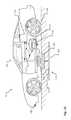
- FIG. 2Ashows a detail view of a vehicle charging panel in a charge receiving position adjacent to a power source in accordance with embodiments of the present disclosure
- FIG. 2Bshows a detail view of a vehicle charging panel in protected positions in accordance with embodiments of the present disclosure
- FIG. 2Cshows a detail view of a vehicle charging panel in a charge receiving position adjacent to a power source in accordance with embodiments of the present disclosure
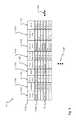
- FIG. 3is a diagram of an embodiment of a data structure for storing information about a charging panel configuration for given roadway types
- FIG. 4is a flow or process diagram of a method of charging an electric vehicle
- FIG. 5is a flow or process diagram of a method of positioning a charging panel of an electrical vehicle to receive a charge
- FIG. 6is a block diagram of a charging panel control system
- FIG. 7Ashows a first state of a graphical user interface used in aligning a charging panel of an electrical vehicle to receive a charge
- FIG. 7Bshows a second state of the graphical user interface of FIG. 7A ;
- FIG. 8is a flow or process diagram of a method of aligning a charging panel of an electrical vehicle to receive a charge
- FIG. 9shows a vehicle in a roadway obstacle environment in accordance with embodiments of the present disclosure.
- FIG. 10is a diagram of an embodiment of a data structure for storing information about sensor configurations for given obstacle risk profile
- FIG. 11is a flow or process diagram of a method of obstacle warning and avoidance
- FIG. 12shows a vehicle in an emergency charging environment in accordance with embodiments of the present disclosure
- FIG. 13is a diagram of an embodiment of a data structure for storing information about a charging panel configuration for given emergency charging environments
- FIG. 14is a flow or process diagram of a method of emergency charging from a roadway vehicle
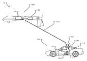
- FIG. 15shows a vehicle in an aerial vehicle charging environment in accordance with another embodiment of the present disclosure
- FIG. 16is a diagram of an embodiment of a data structure for storing information about a charging panel configuration for a given aerial vehicle charging environment
- FIG. 17is a flow or process diagram of a method of charging from an aerial vehicle
- FIG. 18shows a vehicle in an overhead charging environment in accordance with another embodiment of the present disclosure.
- FIG. 19is a diagram of an embodiment of a data structure for storing information about a charging configuration for a given overhead charging environment.
- FIG. 20is a flow or process diagram of a method of charging from an overhead charging system.
- the terms “plurality” and “a plurality” as used hereinmay include, for example, “multiple” or “two or more”.
- the terms “plurality” or “a plurality”may be used throughout the specification to describe two or more components, devices, elements, units, parameters, circuits, or the like.
- armaturemeans a moveable portion of an electromagnetic system or device.
- inductive chargingmeans the use of an EM field to transfer energy between two objects.
- displayrefers to a portion of a screen used to display the output of a computer to a user.
- displayed imageor “displayed object” refers to an image produced on the display.
- a typical displayed imageis a window or desktop or portion thereof, such as an icon.
- the displayed imagemay occupy all or a portion of the display.
- communication deviceany type of device capable of communicating with one or more of another device and/or across a communications network, via a communications protocol, and the like.
- exemplary communication devicesmay include but are not limited to smartphones, handheld computers, laptops, netbooks, notebook computers, subnotebooks, tablet computers, scanners, portable gaming devices, phones, pagers, GPS modules, portable music players, and other Internet-enabled and/or network-connected devices.
- automatedrefers to any process or operation done without material human input when the process or operation is performed. However, a process or operation can be automatic, even though performance of the process or operation uses material or immaterial human input, if the input is received before performance of the process or operation. Human input is deemed to be material if such input influences how the process or operation will be performed. Human input that consents to the performance of the process or operation is not deemed to be “material”.
- touch screenrefers to a physical structure that enables the user to interact with the computer by touching areas on the screen and provides information to a user through a display.
- the touch screenmay sense user contact in a number of different ways, such as by a change in an electrical parameter (e.g., resistance or capacitance), acoustic wave variations, infrared radiation proximity detection, light variation detection, and the like.
- an electrical parametere.g., resistance or capacitance
- acoustic wave variationse.g., infrared radiation proximity detection, light variation detection, and the like.
- a resistive touch screenfor example, normally separated conductive and resistive metallic layers in the screen pass an electrical current. When a user touches the screen, the two layers make contact in the contacted location, whereby a change in electrical field is noted and the coordinates of the contacted location calculated.
- a capacitive layerstores electrical charge, which is discharged to the user upon contact with the touch screen, causing a decrease in the charge of the capacitive layer. The decrease is measured, and the contacted location coordinates determined.
- a surface acoustic wave touch screenan acoustic wave is transmitted through the screen, and the acoustic wave is disturbed by user contact.
- a receiving transducerdetects the user contact instance and determines the contacted location coordinates.
- the touch screenmay or may not include a proximity sensor to sense a nearness of object, such as a user digit, to the screen.
- a wireless devicecan also be used to refer to any device, system or module that manages and/or configures or communicates with any one or more aspects of the network or communications environment and/or transceiver(s) and/or stations and/or access point(s) described herein.
- the components of the systemcan be combined into one or more devices, or split between devices.
- the various links, including the communications channel(s) connecting the elementscan be wired or wireless links or any combination thereof, or any other known or later developed element(s) capable of supplying and/or communicating data to and from the connected elements.
- moduleas used herein can refer to any known or later developed hardware, circuit, circuitry, software, firmware, or combination thereof, that is capable of performing the functionality associated with that element.
- determine, calculate, and compute and variations thereof, as used hereinare used interchangeable and include any type of methodology, process, technique, mathematical operational or protocol.
- FIGS. 1-20embodiments of the electric vehicle charging system 100 and method of use are depicted.
- a charging panel associated with an electric vehicleshould be deployed to charge an energy storage unit of the vehicle.
- an in-roadwaysuch as a parking space
- the automobilemay require, e.g., a charge, in a proper location for charging, sufficient time to receive a charge, etc.
- Conditionsare analyzed by the vehicle and/or the charging system, wherein a charge may be authorized.
- a charging panel or circuitmay be distally disposed on an armature that may hover over a charging circuit in a roadway.
- the armaturemay move in three dimensions and/or in three axes to maintain an optimal distance from the charging circuit but still keep the panel from impacting the roadway or other road hazards.
- a suite of sensorsmay monitor the roadway ahead to allow the armature to adjust to sensed hazards.
- a vehicle 100is shown in a charging environment in accordance with embodiments of the present disclosure.
- the system 10comprises a vehicle 100 , an electrical storage unit 112 , an external power source 116 able to provide a charge to the vehicle 100 , a charging panel 108 mounted on the vehicle 100 and in electrical communication with the electrical storage unit 112 , and a vehicle charging panel controller 112 .
- the charging panel controller 112may determine if the electrical storage unit requires charging and if conditions allow for deployment of a charging panel.
- the vehicle charging panel 108may operate in at least a retracted state and a deployed state ( 108 and 108 ′ as shown is FIG. 1A ), and is movable by way of an armature 204 .
- the charging panel controller 112may receive signals from vehicle sensors 126 to determine, for example, if a hazard is present in the path of the vehicle 100 such that deployment of the vehicle charging panel 108 is inadvisable.
- the charging panel controller 112may also query a vehicle database 113 comprising data structures 114 to establish other required conditions for deployment. For example, the database may provide that a particular roadway does not provide a charging service or the charging service is inactive, wherein the charging panel 108 would not be deployed.
- the power source 116may include at least one electrical transmission line 124 and at least one power transmitter or charging area 120 .
- the charging panel 108may serve to transfer energy from the power source 116 to at least one energy storage unit 112 (e.g., battery, capacitor, power cell, etc.) of the electric vehicle 100 .
- the power source 116may be associated with a particular charging area of a travel environment 102 .
- various charging areas 120 A-Care shown in a vehicle travel environment 102 in accordance with embodiments of the present disclosure.
- the charging areas 120 A, 120 Bmay be positioned a static area such as a designated spot, pad, parking space 140 A, 140 B, traffic controlled space (e.g., an area adjacent to a stop sign, traffic light, gate, etc.), portion of a building, portion of a structure, etc., and/or combinations thereof.
- Some static charging areasmay require that the electric vehicle 100 is stationary before a charge, or electrical energy transfer, is initiated.
- the charging panel 108may make a physical connection with the power source 116 .
- the charging panel 108may include a plug or other protruding feature and the power source 116 may include a receptacle or other receiving feature, and/or vice versa.
- a static charging areamay include a portion of a roadway 104 , street, or other travel path that is configured to provide electrical charging energy to a charging panel 108 of a vehicle 100 .
- the charging areamay be in the roadway 104 , on the roadway 104 , or otherwise adjacent to the roadway 104 , and/or combinations thereof.
- This static charging area 120 Bmay allow a charge to be transferred even while the electrical vehicle 100 is moving.
- the static charging area 120 Bmay include a charging transmitter (e.g., conductor, etc.) that provides a transfer of energy when in a suitable range of a receiving unit (e.g., an inductor pick up, etc.).
- the receiving unitmay be a part of the charging panel 108 associated with the electrical vehicle 100 .
- the charging areamay be a moving charging area 120 C.
- Moving charging areas 120 Cmay include charging areas associated with one or more portions of a vehicle, a robotic charging device, a tracked charging device, a rail charging device, etc., and/or combinations thereof.
- the electrical vehicle 100may be configured to receive a charge, via the charging panel 108 , while the vehicle 100 is moving and/or while the vehicle 100 is stationary.
- the electrical vehicle 100may synchronize to move at the same speed, acceleration, and/or path as the moving charging area 120 C.
- the moving charging area 120 Cmay synchronize to move at the same speed, acceleration, and/or path as the electrical vehicle 100 .
- the synchronizationmay be based on an exchange of information communicated across a communications channel between the electric vehicle 100 and the charging area 120 C. Additionally or alternatively, the synchronization may be based on information associated with a movement of the electric vehicle 100 and/or the moving charging area 120 C. In some embodiments, the moving charging area 120 C may be configured to move along a direction or path 132 from an origin position to a destination position 120 C′.
- a transformer 136 A, 136 Bmay be included to convert a power setting associated with a main power supply to a power supply used by the charging areas 120 A-C.
- the transformer 136 A, 136 Bmay increase or decrease a voltage associated with power supplied via one or more power transmission lines.
- a deployment or charging panel controller 110 controllere.g., a hardware device comprising a processor configured to control an actuation of the charging panel 108 , etc. may determine whether to deploy the charging panel 108 of the electric vehicle 100 .
- Factors, or conditions, contributing to this determinationmay include, but is in no way limited to, charge level of the vehicle 100 , location of the vehicle 100 , location of a charging area 120 , a capability of the charging area 120 (e.g., energy transfer rating, compatibility with the charging panel 108 and/or vehicle 100 , static charging capability, moving charging capability, etc.), obstacles between the charging panel 108 and the charging area 120 , anticipated travel path of the vehicle 100 , time required to charge, travel time, stopping time, etc., and/or combinations thereof. Among other things, these factors may be analyzed to determine whether the electric vehicle 100 is capable of receiving a charge (e.g., enough time to receive a charge, etc.).
- a chargemay be authorized.
- the authorization of a chargemay include receiving a charge initiation key (e.g., from an authentication server, one or more components associated with the charging area, etc.). In any event, the authorization of the charge causes the charging panel 108 of the vehicle 100 to deploy.
- FIG. 2Ashows a detail view of a vehicle charging panel 108 in a charge receiving position adjacent to a power source 120 in accordance with embodiments of the present disclosure.
- the charging panel 108 of a vehicle 100may need to be deployed or moved into a position for receiving a charge 212 . This position may be based on specific power transfer requirements, on a specific distance of the charging panel 108 relative to the charging area 120 , safety requirements, and/or a designated distance of operation for effecting an electrical energy transfer, or charge 212 , operation.
- the charging panel 108may be actuated from a retracted or concealed position into a deployed, or charge-receiving, position as described above, the charging panel 108 may need to be moved, at any time, in response to a detected condition.
- a detected conditionmay be an obstacle, obstruction, object, natural condition, chemical, etc., and/or combination thereof that can potentially damage or otherwise contact the charging panel 108 .
- a charging panel 108may be disposed on an exposed side of a vehicle 100 (e.g., the underside of the vehicle 100 , etc.). When the charging panel 108 is actuated into a deployed position, the charging panel 108 may be vulnerable to damage from variations in a roadway or some other condition.
- an object on the road 104may contact and/or damage the charging panel 108 .
- the embodiments described hereinmay account for variations in terrain, objects, and/or other conditions and selectively move the charging panel 108 from a deployed position to a concealed or at least partially concealed position.
- a shield 220may be inserted or positioned between the object/hazard and the charging panel 108 to, among other things, prevent damage to the charging panel 108 .
- the charging panel 108 and/or circuitmay be distally disposed on an armature that is configured to hover over a charging circuit 116 in a roadway 104 .
- this distance 208may be predetermined or preset for energy transfer requirements and/or safety (e.g. via query by controller 110 to database 113 ), however embodiments disclosed herein should not be so limited.
- the armature 204may move in one or more dimensions and/or axes to maintain an optimal or preset distance 208 from the charging circuit 120 while preventing the charging panel 108 from impacting the roadway 104 , environmental, and/or other hazards.
- one or more sensors 126may monitor the roadway 104 around a vehicle 100 (e.g., an area or volume of space ahead of or in proximity to a vehicle 100 , etc.) at least at a detection distance from the armature 204 . This sensor monitoring can allow the armature 204 to timely adjust position in response to at least one condition and/or hazard detected by the one or more sensors 126 . Height or separation distance between a point on the charging panel 108 and the roadway surface 104 and/or charging panel 120 is provided by one or more separation sensors 127 .
- a minor positional adjustmentmay be all that is required to avoid contact with an object or to avoid a hazard.
- a movement controller(as contained in controller 110 —see e.g. FIG. 6 ) may determine to move the charging panel 108 and/or armature 204 along a direction 214 parallel to the surface of the roadway. For instance, as a vehicle 100 is travelling along a path in a first direction 214 B, a hazard may be detected in the path via the one or more sensors 126 described herein.
- the sensor informationmay be used by a controller of the vehicle 100 to move the charging panel in a direction different 214 A, 214 C from the first direction 214 B.
- the direction different 214 A, 214 C from the first direction 214 Bmay be orthogonal to the first direction 214 B.
- the direction different 214 C (shown going into and coming out of the page in FIG. 2A ) from the first directionmay be along a plane that is parallel to the surface of, or hypothetical plane established by, the roadway 104 .
- the minor positional adjustment to the charging panel 108may be enough to avoid a collision, impact, and/or other contact with the hazard.
- the charging panel 108may be attached to at least one suspension component of the vehicle 100 .
- the charging panel 108may be moved via a mechanical connection and based on a movement of at least one suspension element of the vehicle 100 .
- the movementmay be driven by a mechanical and/or electrical component, actuator, linkage, solenoid, or other mechanism/device. In any event, the movement may be effected in response to detecting a mechanical movement of the suspension, the vehicle 100 , and/or the roadway 104 relative to the charging panel 108 , etc.
- a movement of the charging panel 108may not be feasible or even possible.
- the charging panel 108may not be capable of moving quick enough (e.g., from an exposed position to a completely, or at least partially, concealed position, etc.) to prevent impact.
- a shield 220 or protective panelmay be actuated, deployed, inserted, or otherwise positioned into a position 220 ′ between the obstacle/object and the charging panel 108 . When in this position, the shield 220 may serve to absorb, deflect, or otherwise minimize the effect of an impact or shock.
- Positioning of the shield 220may include a spring-loaded actuation, mechanical actuation, electrical actuation, gas actuation, fluid actuation, an explosive deployment (e.g., similar to an airbag or safety restraint system initiation and deployment, sodium azide, potassium nitrate, etc.), etc., and/or combinations thereof.
- the shield 220 positioningmay be performed in a fraction of the time it takes the charging panel 108 to deploy and/or retract.
- one or more sensors 126may be used to detect an obstacle, object, or other hazard.
- the one or more sensors 126may include, but are in no way limited to, image sensors, radio frequency sensors, laser radar or ladar sensors, infrared sensors, mechanical sensors (e.g., strain gauges, pressure sensors, brush sensors, leaf spring sensors, cantilevered motion sensors, etc.), electrical energy sensors, etc., and/or combinations thereof.
- an array of sensors 126may be used to detect an object and determine, or extrapolate, a position of the object at a particular time. For instance, a rock may have been set into motion via making contact with a moving vehicle 100 travelling along a roadway 104 .
- the rockmay be bouncing toward the side 216 of the electrical vehicle 100 having the deployed, or at least partially deployed, charging panel 108 .
- the array of sensors 126 in this examplemay determine a trajectory of the rock.
- a controller of the vehiclemay initiate a command to one or more of the movable armature 204 , shield 220 , charging panel deployment mechanism, retracting device, and/or other device to protect the charging panel from damage.
- the protection of the charging panel 108may include moving the charging panel 108 to an at least partially concealed position and/or moving a shield 220 into a position 220 ′ that at least partially conceals the charging panel 108 .
- the shieldmay be a brush, such as a wired cylindrical brush, to clear or receive debris such as roadway debris.
- FIG. 2Cshows a detail view of a vehicle charging panel 108 in a charge receiving position adjacent to a power source wherein the charging panel is an airfoil shape.
- the charging panel 108may comprise an airfoil flap 108 A.
- the airfoil shapein some situations may provided improved control and/or positioning and/or structural stability to the charging panel 108 with respect to maintaining charging distance to charging panel 120 (as embedded in a roadway or flush with a roadway surface). More specifically, when the vehicle 100 is moving at sufficient speed, aerodynamic forces or loads will be generated and imposed on any structures fitted between the bottom of the vehicle and the roadway.
- FIG. 6details the operation of such a feedback control system for positioning of the charging panel 108 .
- sensor 127would be disposed on armature 204 and/or charging panel 108 in a manner so as not to disturb the airfoil shape. Also, the flap 108 A affords additional control. Furthermore, the manner in which charging panel 108 in mounted in FIG. 2C would nominal produce a downward lifting force on the panel 108 given the airfoils chamber relative to the roadway. The airfoil shape may also be mounted so as to produce an upward listing force. In other embodiments, alternative aerodynamic shapes are positioned upstream and/or downstream of the charging panel to improve airflow (eg straighten incoming airflow) or for other reasons as know to those skilled in the art.
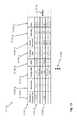
- FIG. 3is a diagram of an embodiment of a data structure 114 for storing information about a charging panel configuration for given roadway types.
- the data structuresare stored in vehicle database 113 and accessible by vehicle controller 110 .
- the data contained in data structure 114enables, among other things, for the vehicle controller 110 to initially position and to control the position of a deployed charging panel 108 .
- Exemplar datamay comprise panel type 115 A meaning type of charging panel configured to vehicle comprising a flat panel (eg of FIGS. 2A-B and an airfoil e.g. of FIG. 2C ); roadway type 115 B e.g. an interstate (Colorado Interstate 25) or state highway e.g. Colorado Highway 36; a nominal recommended separation distance 115 C between a set datum e.g.
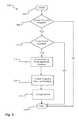
- FIG. 4provides a flow chart illustrating an exemplary method of use of charging an electric vehicle 100 by way of the system 10 .
- the method 400starts at step 404 and ends at step 428 .
- step 408the method 400 queries as to whether charging is required by the electric vehicle 100 . If charging is required, the method proceeds to step 412 . If charging is not required, the method 400 proceeds to step 428 and the method 400 ends.
- step 412a query is made as to if a power source is available. That is, is the energy source (such as provided in a various charging area 120 A-C) able to provide a charging service to electric vehicle 100 . The query may be facilitated and/or determined by way of controller 110 and database 113 . If NO (that is, no charging available), the method proceeds to step 428 and ends. If the result of the query of step 412 is YES, the method proceeds to step 416 .
- a queryis made as to whether the vehicle 100 and/or charge panel 108 is configured to receive the charging from power source.
- a querymay be facilitated by communications between vehicle “smart” control systems (eg controller 110 ) of one or both of vehicle 100 and charging area 120 A-C.
- the querymay be facilitated and/or determined by way of controller 110 and database 113 .
- incompatibilitiesmay include min/max energy transfer thresholds (eg voltages). If NO (ie the vehicle is incompatible with the power source) the method proceeds to step 428 and ends. If the result of the query of step 516 is YES, the method proceeds to step 420 .
- a queryis made to determine if conditions allow charging panel to be deployed.
- database 113may be queried to determine if power is available from a particular roadway. Additionally or alternatively, one or more sensors 126 may determine that an obstacle presents undue risk of damage to the charging panel so as to determine that conditions do not allow charging panel deployment. If the answer to query of step 420 is YES, the charging panel is deployed and the method continues to step 424 . If NO the method proceeds to step 428 and ends. At step 424 the deployed charge panel 108 receives a charge and the method proceeds to step 528 wherein the method ends.
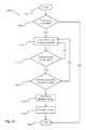
- FIG. 5provides a flow chart illustrating an exemplary method of positioning a charging panel 108 of an electrical vehicle 100 to receive a charge by way of the system 10 .
- the method 500starts at step 504 and ends at step 528 .
- step 508the method queries as to whether charging is required by the electric vehicle 100 . If charging is required, the method proceeds to step 512 . If charging is not required, the method 500 proceeds to step 528 and the method 500 ends.
- a queryis made as to if a power source is available. That is, is the energy source (such as provided in a various charging area 120 A-C) able to provide a charging service to electric vehicle 100 ? The query may be facilitated and/or determined by way of controller 110 and database 113 . If NO (that is no charging available), the method proceeds to step 528 and ends. If the result of the query of step 512 is YES, the method proceeds to step 516 .
- the controller 110queries the database 113 to determine the nominal conditions for deployment of the charging panel 108 . For example (with regards to FIG. 3 ), if the charging panel is of type “Airfoil A4” and vehicle 100 is traveling on CO I-25, the charging panel is set to separation distance 8 inches and with pitch and flap at 0 degrees. The method then proceeds to step 520 wherein the charging panel 108 is positioned to the nominal set deployment conditions established in step 520 . (In one embodiment, prior to step 520 , a query is made, akin to step 420 of method 400 , to determine if conditions allow for deployment of the charging panel.) At step 524 the deployed charge panel 108 receives a charge and the method proceeds to step 528 wherein the method ends.
- FIG. 6is a block diagram of a charging panel control system 600 .
- the control system 600is a feedback control system to control the separation distance between the charging panel 108 and the roadway (or more generally, the charging source). Selected separation distance is input (as determined by way of query to database 113 or manually entered by user) and compared with a measured separation distance (as from a separation distance sensor 127 ) to compute an error signal.
- the error signalis received by the controller 110 to determine control inputs to actuator of armature 204 which moves the charging panel 108 .
- the error signalwill typically be non-zero due to disturbances to the charging panel, such as aerodynamic loads generated while the vehicle is in motion.
- the controller 110may employ any known types of feedback control known to those skilled in the art, comprising stochastic control, proportional, interal and/or derivative control, non-linear control and deterministic control.
- a plurality of sensor 127 inputsare provided and/or a plurality of separation distances and/or loading measures are controlled.
- a pair of positional sensorsmay be positioned at ends of the leading edge of an airfoil type charging panel whereby pitch and/or roll are controlled as well as distance from the roadway.
- a loading sensormay be positioned on the armature to measure the loading imparted to the armature shaft, so as to provide an ability to, for example, determine if a threshold value for do-not-exceed loading (as stored in database 113 ) has been exceeded.
- the charging area 120 A-C and/or power source 116provides notice to the vehicle 100 , controller 110 , and/or vehicle user that charging service is available and/or terms and conditions thereof.
- the noticemay comprise targeted communications eg by texting to vehicles within a selectable distance.
- the content of the noticemay comprise: the availability of charging, and terms and conditions of charging (cost, payment types, amount available, duration of charging time, etc).
- the noticemay comprise a physical mounted advertisement that charging is available, not unlike a taxi “off duty” or “on duty” light mounted on a taxi rooftop.
- the charging panel 108is maneuvered manually, e.g. by a vehicle user, a vehicle passenger, or an attendant at a stationary charging environment.
- the charging panel 108through use of the feedback controller 110 described in one embodiment as FIG. 6 , maintains a “terrain following” i.e. “TF” mode wherein the planar lower surface of the charging panel 108 maintains a constant height above (or “altitude”) above the roadway surface.
- TF“terrain following”
- the planar lower surface of the charging panel 108maintains a constant height above (or “altitude”) above the roadway surface.
- TF“terrain following”
- the planar lower surface of the charging panel 108maintains a constant height above (or “altitude”) above the roadway surface.
- the separation distance 208the one variable being a vertical distance.
- the controller 108may maintain more than one variable.
- roadway crownmay, in one embodiment, be a data record maintained in database 113 .
- vehicle sensors 126may comprise one or more sensors able to measure roadway crown and/or other features of a non-planar roadway and/or a non-parallel relationship between the lower surface of the charging panel and the roadway (e.g. vertical distance sensors at each corner of the vehicle measuring distance from vehicle to the roadway).
- FIGS. 7A-Bshow representative states of a graphical user interface (GUI) used in aligning a charging panel of an electrical vehicle to receive a charge. More specifically, FIGS. 7A-B depict graphical user interfaces 700 displaying feedback adjustment image one 708 and feedback adjustment image two 708 ′ in accordance with embodiments of the present disclosure.
- GUIgraphical user interface
- FIGS. 7A-Bdepict graphical user interfaces 700 displaying feedback adjustment image one 708 and feedback adjustment image two 708 ′ in accordance with embodiments of the present disclosure.
- methods and systemsare described that provide an electric vehicle 100 with the ability to properly align the charging panel 108 of the vehicle 100 over a charging circuit or power source 116 . This system may continually and dynamically determine a position or location of the charging panel 108 relative to at least one of the charging circuit components aka power source 116 .
- the dynamic position or locationmay be provided to a driver of the vehicle via at least one graphical user interface (GUI) 700 of a display device 704 to allow the driver to make any adjustments to the position of the vehicle 100 and/or the charging panel 108 .
- GUIgraphical user interface
- the GUI 700may show a vehicle image aka feedback adjustment image 708 relative to an alignment line, or centerline aka power source centerline icon 412 , of an image representing a charging element aka power source icon 416 .
- the graphical outpute.g., showing the relative position of the components in the charging system, etc.
- the at least one GUI 700changes (e.g., a changed representative image 708 ′, of the vehicle 100 may move relative to the centerline 712 and/or image representing the charging element aka power source icon 716 , or vice versa, etc.) to reflect the changed position.
- This continual updating of the GUI 700 and the relative charging components positioncan provide a driver of the vehicle 100 with a feedback loop by which the driver can adjust a position of the charging panel 108 and/or the vehicle 100 to obtain an optimal charging alignment between the charging panel 108 and the at least one charging circuit component 116 .
- a feedback recommendation aka alignment instruction 724may be displayed to a portion of the GUI 700 .
- the feedback recommendation 724may provide the driver with alignment instructions and/or advice for adjusting a position of the vehicle 100 relative to the charging circuit 116 .
- alignment instructionsmay comprise more than a horizontal separation distance adjustments, e.g. both a horizontal and a vertical alignment or position instructions, or a horizontal alignment instruction and an angular position.
- the angular alignment adjustmentmay comprise a yaw alignment command, which may be particularly important if the vehicle is moving and the power sources are multiple sequential power sources embedded in a roadway.
- the at least one charging circuit component 116may be in communication with the vehicle, and/or a mobile device associated with a user of the vehicle 100 (e.g., the driver, etc.).
- a mobile deviceassociated with a user of the vehicle 100 (e.g., the driver, etc.).
- the electrical vehicle 100can receive a charge while moving (e.g., in a moving charge area scenario, a static charging area disposed along a length of a travel path 104 , etc., and/or combinations thereof)
- the relative position of the charging panel 108 /vehicle 100 to the at least one charging circuit component 116can be presented (e.g., via the GUI 400 , etc.) to allow driving changes to be made and for the vehicle 100 /charging panel 108 to be properly aligned.
- the orientation of the vehicle 100 and/or the charging panel 108may be based on sensor input from one or more vehicle sensors and/or from one or more sensors exterior to the vehicle 100 .
- the alignmentmay be a function of an onboard application on the vehicle 100 or on a device (e.g., a mobile device of a vehicle driver, vehicle owner, etc.).
- the alignment feedback provided to the vehicle 100 , the GUI 700 , a driver of the vehicle 100 , and/or other control component associated with the vehicle 100may be used by a vehicle control system to automatically adjust the position of the vehicle 100 and/or the charging panel 108 relative to the at least one charging circuit 116 .
- the position of the charging panel 108may be required to be within an optimal charge range of the at least one charging circuit component 116 .
- This optimal charge rangemay include a vertical distance between the charging panel 108 and the at least one charging circuit component 116 and/or a horizontal distance between a portion of the charging panel 108 and a portion of the at least one charging circuit 116 .
- the optimal charging rangemay include a distance 208 between a specific portion of the charging panel 108 and a specific portion of the at least one charging circuit 116 .
- the optimal charging rangemay be defined as the position of the charging panel 108 relative to the at least one charging circuit component 116 that is capable of effecting an efficient transfer of energy.
- the optimal charging range, and similar charging parameterse.g. separation distance between charging panel and roadway surface
- the efficient transfer of energymay include a percentage, an allowable loss amount, and/or other value defining the electrical energy transfer from the at least one charging circuit component 116 to the charging panel 108 . As can be appreciated, this information may be displayed to the GUI 700 .
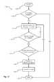
- FIG. 8provides a flow chart illustrating an exemplary method of aligning a charging panel 108 of an electrical vehicle 100 to receive a charge by way of the system 10 .
- the method 800starts at step 804 and ends at step 824 .
- a sensormeasures the alignment of the vehicle-mounted charging panel 108 with respect to the charging power source 116 .
- the alignment sensormay be mounted on the vehicle 100 and/or on the ground, to include in proximity to the power source 116 .
- the alignment sensormeasures a distance between a centerline of the power source 116 and the centerline of the charging panel 108 , for example a linear separation distance.
- the senortransmits the sensor measurement data so as to be received by an alignment controller.
- the transmittalmay be through any means known to those skilled in the art, such as by wireless communication.
- the sensormay transmit in an analog and/or digital manner.
- the sensormay be a plurality of sensors, and may broadcast at selected frequencies and/or power levels.
- the alignment controllerreceives the sensor measurement data and determines if any alignment required.
- the sensormay provide that the linear separation distance is 0.5 meter, thereby determining that an alignment adjustment of 0.5 in a particular direction is required for optimal energy transfer between the charging panel 108 and the power source 116 .
- the alignment controllermay also determine additional data, such as the power efficiency between the charging panel 108 and the power source 116 (e.g. in FIG. 7B the power transfer efficiency is provided as 43%.)
- the alignment controllermay provide text description as to directionality (e.g. move left or right) as provided by alignment instruction 724 .
- the alignment controllermay provide alignment data (e.g., comprising linear separation distance, power transfer level, directionality for improved alignment, etc) by way of a graphical user interface 700 and/or may automatically adjust the position of the vehicle and/or charging panel 108 for improved alignment.
- the alignment controllermay provide signals to the actuator so as to minimize or eliminate the alignment error or alignment required, or to effect the movement of the charging panel via the actuator and/or armature.
- the alignment controllermay provide signals to adjust the charging panel in more any of three translation positions and/or angular positions (as shown, e.g. in FIG. 2C .)
- the alignment controllermay also perform signal processing to blend multiple measurements from one or more sensors.
- the alignment controllermay also provide feedback control with respect to the linear separation, as described above with respect to FIG. 6 .
- the methodends at step 824 .
- FIGS. 9-11describe aspects of an electric vehicle charging device obstacle avoidance system and method of use.
- FIG. 9shows a vehicle in a roadway obstacle environment
- FIG. 10provides a diagram of an embodiment of a data structure for storing information about sensor configurations for a given obstacle risk profile
- FIG. 11provides a flow or process diagram of a method of obstacle warning and avoidance.
- FIG. 9shows a block diagram of a vehicle 100 and obstacle detection system in accordance with embodiments of the present disclosure.
- the one or more sensors 126 A-Fmay be road-focused radar, moving sensors, and/or other stationary or mounted sensors.
- the sensors 126 A-Fmay include one or more physically active sensors, including brush sensors, physical contact sensors, etc. These more physically active sensors may detect the obstacle and may even alter a condition associated with the obstacle 928 .
- At least one physical component of the more active sensorsmay physically move obstacles 928 , mitigate the effect of an impact of an obstacle 928 , and/or even come into physical contact with those obstacles 928 .
- the physical contact with the obstacle 928may produce the warning.
- a more active, or physical contact, sensormay include a wedge component, plow-shaped component, and/or deflecting member having a strain gauge attached thereto.
- the more active sensormay include a mechanical portion coupled thereto that is designed to contact an object 928 .
- the contact with the object 928may be measured as a stress, strain, electrical signal (e.g., potential difference, capacitance change, impedance, etc.), mechanical contact switch actuation, etc., and/or combinations thereof.
- the sensorupon detecting the contact, may provide a signal to a controller 110 .
- the controller 110may interpret the signal and determine to send a retraction command signal to one or more protective devices 226 configured to move and/or protect the charging panel 108 .
- the charging panel 108may be made adjusted or moved (e.g., retracted, concealed, deployed, etc.), by the controller 110 , in response to receiving and interpreting the detection signal within fractions of a second.
- the time between detecting the obstacle 928 , or contact, and the controller 110 initiating a movement command configured to retract the charging panel 108may be less than 300 milliseconds.
- the time between detecting the hazard 928 , or contact, and the controller 110 initiating a movement command configured to retract the charging panel 108may be less than 100 milliseconds.
- FIG. 10is a diagram of an embodiment of a data structure 914 for storing information about sensor configurations for given obstacle risk profiles.
- the data structuresare stored in vehicle database 113 and accessible by vehicle controller 110 .
- the data contained in data structure 914enables, among other things, for the vehicle controller 110 to configure, operate, initially position and/or to control the one or more sensors 126 , such as the sensors 126 A-F depicted in FIG. 9 .
- Exemplar datamay comprise obstacle risk 915 A, sensor type 915 B, environmental conditions 915 C, shield deployment 915 D, and other 915 E which may comprise further operational parameters of a given sensor.
- Further data fields 915 K, 915 Lare possible.
- Obstacle risk 915 Amay provide a measure of the relative risk or likelihood of obstacles or hazards that may present themselves to a deployed charging panel 108 .
- a roadway undergoing maintenanceis more likely to present hazards (e.g. fallen barricade in the roadway, foreign objects such as bolts or other construction hardware in the road, etc) than one not undergoing such maintenance.
- Sensor type 915 Bmay comprise any sensor types known to those skilled in the art to provide obstacle warning, comprising ladars, radars, and cameras of various bands such as IR and visible.
- Such sensorsmay comprise scanning sensors and fixed direction sensors, and may be controlled automatically, semi-automatically, or manually by an occupant of the vehicle.
- Additional characteristics of any particular sensor typemay be provided in the Other 915 E data field, providing characteristics comprising signal/noise ratios which influence valid “hits” or indicators of the presence of an object, sensitivity levels (ie “trip thresholds”) for such obstacle detection hits, sensor power or energy or emission levels, scanning and/or dwell times or durations, frequency bandwidths, pulse characteristics (if a pulsed sensor) such as wavelength shapes (eg square pulse, etc), and shape of sensor emission (eg, fan shape or pencil-beam shape).
- Environmental conditions 915 Cmay comprise visibility data (eg daylight, nighttime), humidity data (e.g. rain or fog).
- Shield deployment 915 Dmay comprise on/off or yes/no deployment of a protective shield surrounding the charging panel (such a protective shield may produce unwanted aerodynamic drag and therefore not typically be deployed). Further parameters may comprise speed of vehicle (eg a higher speed may correlate to a higher obstacle risk level).
- Data structure 914may be accessible automatically by controller 110 and/or by a vehicle user. Data structure 914 may comprise elements and characteristics of data structure 114 .
- FIG. 11provides a flow chart illustrating an exemplary method of obstacle warning and avoidance.
- the method 1100starts at step 1104 and ends at step 1128 .
- the method 1100queries as to whether the charging panel is deployed. (In one embodiment, the step 420 of method 400 are followed so as to determine if conditions allow the charging panel to be deployed.) In one embodiment, any deployment other than fully retracted/stowed results in a response of Yes. If the charging panel is deployed, the response to the query is a Yes and the method 1100 proceeds to step 1112 . If the response to the query is a No, the method 1100 proceeds to step 1128 and the method 1100 ends.
- the one or more obstacle sensorsare operated.
- the one or more sensorsare simply turned on or activated.
- the method at step 1112interacts with database 113 and associated sensor data structures 914 to configure the one or more sensors.
- Such interactionmay occur automatically between controller 110 and database 113 , or may be replaced or supplemented with vehicle occupant input.
- a vehicle occupantsuch as the driver, may input (through, for example, a dashboard graphical user interface or a mobile device such as a smartphone) his/her assessment of the obstacle risk and her requirement to activate a specific sensor in a specific manner. That is, the driver may request that MMW radar one and IR camera three be activated.
- the operation of the one or more sensorsmay involve occasional or recurring calibration operations (e.g. to provide ground truthing data so as to limit false positives and/or to truth a sensor against sensor data simply providing measurements to the roadway ahead). With the one or more sensors operating, the method 1100 proceeds to step 1116 .
- the received obstacle sensor datais analyzed.
- the analysismay occur by the controller 110 , and may comprise any signal processing technique known to those skilled in the art, to include the types of control and/or signal processing algorithms described above in relation to FIG. 6 .
- the received sensor datamay require sensor fusion techniques, in particular in configurations where multiple measurements are provided of a particular location ahead or near the vehicle, either by a single sensor or a plurality of sensors or similar and/or different type.
- the method 1100then proceeds to step 1120 .
- the method 1100queries as to whether the analysis of step 1116 determined that a hazard or obstacle in the pathway of the vehicle 100 requires action. If the response to the query of step 1120 is No, the method 1100 returns to step 1108 . If an action is required (that is, the response to the query is Yes and obstacle avoidance is required), the recommended action to effect is determined.
- the recommended actionmay be a function of the warning systems and/or damage prevention capabilities of the system 10 . For example, if the obstacle is determined to be just within a selectable vehicle pathway perimeter, the action may be a visual and/or audio warning to the GUI and/or mobile device of a vehicle occupant. However, if the obstacle is determined to be a more severe threat (e.g.
- the actionmay comprise immediately retracting the charging panel and/or issuing a visual and/or audio warning to take evasive action (eg bear left.)
- the systemautomatically maneuvers the vehicle to attempt to avoid the obstacle.
- the vehicledeploys one or more physically active elements, such as a protective cage surrounding the charging panel and/or one or more protective devices 226 . The method 1100 then proceeds to step 1124 .
- step 1124the recommended action, as determined at step 1124 , is executed.
- the method 1100then proceeds to step 1128 .
- FIG. 12shows a vehicle in an emergency charging environment in accordance with embodiments of the present disclosure.
- a specially-designed “tow truck” or other emergency assistance vehicleprovides a charge to the electric vehicle.
- the emergency vehiclecomprises a charging panel or plate that deploys or extends so as to position below the electric (targeted) vehicle, wherein an emergency (or routine) charge is provided.
- the emergency vehiclecan include a battery pack and a charging circuit to deliver a partial or complete charge to the vehicle.
- This vehiclemay be the equivalent of AAA bringing a gallon of gas to a stranded motorist.
- the emergency charging vehicle 1200is a road vehicle, such as a pick-up truck, as shown in FIG. 12 .
- the emergency charging vehicle 1200is configured to provide a charge to a charge receiver vehicle 100 , such as an automobile, as shown in FIG. 12 .
- the emergency charging vehicle 1200comprises an energy source i.e. a charging power source 116 and a charge provider controller 122 in communication with the charging power source 116 .
- the emergency charging vehicle 1200provides a towed and/or articulated charger plate 120 , as connected to the emergency charging vehicle 1200 by connector 1250 .
- the connector 1250may comprise a chain, rope, rigid or semi-rigid tow bar or any means to position charger plate 120 near the charging panel 108 of vehicle 100 .
- Charge or power output of charging power source 116is provided or transmitted to charger plate 120 by way of charging cable or wire 1240 .
- the charging cable 1240is non-structural, that is, it provides little or no structural support to the connection between emergency charging vehicle 1200 and charging panel 108 .
- Charging panel 108(of vehicle 100 ) receives power from charger plate 120 .
- Charger plate 120 and charging panel 108may be in direct physical contact or not in direct physical contact, but must be at or below a threshold separation distance to enable charging, such as by induction.
- Charger plate 120may comprise wheels or rollers so as to roll along roadway surface.
- Charger plate 120may also not contact the ground surface and instead be suspended above the ground; such a configuration may be termed a “flying” configuration.
- charger plateIn the flying configuration, charger plate may form an aerodynamic surface to, for example, facilitate stability and control of the positioning of the charging plate 120 .
- Energy transfer or charging from the charger plate 120 to the charge receiver panel 108is through inductive charging (i.e. use of an EM field to transfer energy between two objects).
- the charging panel 108provides received power to energy storage unit 112 directly or by way of charging panel controller 110 . In one embodiment, the receipt and/or control of the energy provided via the charging panel 108 is provided by charging panel controller 110 .
- Charging panel controller 110may be located anywhere on charge receiver vehicle 100 , to include, for example, the roof, side panel, trunk, hood, front or rear bumper and wheel hub of charge receiver 100 vehicle.
- charging panel 108may be deployable, ie may extend or deploy only when charging is needed.
- charging panel 108may typically stow flush with the lower plane of vehicle 100 and extend when required for charging.
- charger plate 120may, in one embodiment, not be connected to the lower rear of the emergency charging vehicle 1200 (as depicted in FIG. 12 ) by way of connector 1250 and may instead be mounted on the emergency charging vehicle 1200 , to include, for example, the roof, side panel, trunk, hood, front or rear bumper and wheel hub of emergency charging vehicle 1200 .
- Connector 1250may be configured to maneuver connector plate 120 to any position on emergency charging vehicle 1200 so as to enable charging.
- Control of the charging and/or positioning of the charging platemay be manual, automatic or semi-automatic; said control may be performed through a GUI engaged by driver or occupant of receiving vehicle and/or driver or occupant of charging vehicle.
- FIG. 13is a diagram of an embodiment of a data structure for storing information about an emergency charging panel configuration for given emergency charging environments.
- the emergency charging data structures 1314are stored in vehicle database 113 and accessible by vehicle controller 110 .
- the data contained in data structure 1314enables, among other things, for the vehicle controller 110 to initially position and to control the position of a deployed charging panel 108 for given emergency charging type and/or conditions.
- Exemplar datamay comprise emergency charging type 1315 A, meaning a “contact” or a “flyer” type of charging plate 120 , as provided by emergency charging vehicle 1200 .
- a contact charging typeis a charging plate 120 that makes physical contact with the charging panel 108 of the electric vehicle 100 .
- a flyer charging typeis a charging plate 120 that does not make (intentional) physical contact with the charging panel 120 of the vehicle 100 , but instead is suspended or flies above the roadway surface and below the charging panel 108 .
- charging plate 120 and charging panel 108may be configured in various geometrical shapes, to include a flat panel and an airfoil (see, e.g. flat panel shape of FIGS. 2A-B and airfoil shape of FIG. 2C ).
- a nominal recommended separation distanceis provided as 1315 B between a set datum e.g. the lower surface of the panel and the roadway, e.g. 8 inches.
- Charge rate 1315 Cmay be set to numerical values or a qualitative value (e.g. low, medium, high which may correspond to a charging transmission level).
- a pitch angle 1315 D for the charging panel 108may be established, and roadway type 1315 E (shown with characteristics comprising X, Y and Z representing roadway characteristics e.g. X may indicate a highway, Y may indicate a roadway with some active construction, and Z may indicate a roadway with significant crown).
- a maximum vertical load 1315 Frepresents a maximum allowed to the charging panel 108 .
- An on/off toggle of shieldingis data item 1315 G, which references deployment (i.e. “on”) or non-deployment (i.e. “off” on stowed) of an EM shield cage at least partially surrounding charging panel 108 .
- the Other data type of 1315 Hmay comprise other data items involved in electrical charging such as voltage levels, current values, etc as known to those skilled in the art, and operational data such as costs of charging for a given emergency charging type or charging provider. Further data fields 1315 L and 1315 M are possible.
- FIG. 14provides an exemplar method of use 1400 of the emergency charging from a roadway vehicle system 100 .
- the methodstarts at step 1404 and ends at step 1432 .
- step 1408the method queries as to whether charging is available by emergency charging vehicle 1200 . That is, a query is made as to whether the energy source (i.e. charging power source 116 ) is able to provide a charging service to a charging panel 108 of vehicle 100 . If NO, the method proceeds to step 1432 and ends. (Alternatively, the vehicle 100 may return to a home base station or similar and recharge its energy source i.e. recharge energy storage unit 112 .) If the result of the query of step 1408 is YES, the method proceeds to step 1412 wherein notice is provided (by one or more emergency charging vehicles 1200 ) that charging is available. The notice may comprise targeted communications e.g. by texting to vehicles 100 within a selectable distance.
- the noticemay comprise targeted communications e.g. by texting to vehicles 100 within a selectable distance.
- the content of the noticemay comprise: the availability of charging, and terms and conditions of charging (cost, payment types, amount available, duration of charging time, etc).
- the noticemay comprise a physical mounted advertisement (eg a lighted sign on emergency charging vehicle 1200 ) that charging is available, not unlike a taxi “off duty” or “on duty” light mounted on emergency charging vehicle 1200 rooftop.
- a queryis made as to whether vehicle 100 has requested or requires or seeks a charge.
- charging panel controller 110may monitor a state or status of charging (e.g. battery is charged at 32%, or battery charging level drops below a selectable threshold value e.g. below 10%) of the energy storage unit 112 of vehicle 100 to determine if charging is recommended or required.
- a usersuch as a driver or passenger, may also request that the vehicle be charged. If NO, the method proceeds back to step 1412 . If YES, the method proceeds to step 1420 .
- a queryis made as to whether the charge receiver 100 vehicle is configured to receive the charging from emergency charging vehicle 1200 .
- a querymay be facilitated by communications between vehicle “smart” control systems aboard one or both of emergency charging vehicle 1200 and charge receiver vehicle 100 , comprising communications between charge provider controller 122 and charging panel controller 110 .
- incompatibilitiesmay include min/max energy transfer thresholds (e.g. voltages).
- the positioning of the charging plate 108may comprise selection of initial or nominal positioning via data contained in vehicle database 113 through emergency charging data structure 1314 and emergency charging data structure fields 1315 A-M.
- the method 1400then continues to step 1428 wherein a charge is provided by power source 116 via charging plate 120 to charging panel 108 so as to power or charge energy source 112 or vehicle 100 .
- the vehicle 100may alternatively or additionally provide a charge to the emergency vehicle 1200 via electrical energy transfer from charging panel 108 to charging plate 120 .
- the method 1400ends at step 1432 .
- FIG. 15shows a vehicle in an aerial vehicle charging environment in accordance with another embodiment of the present disclosure.
- an aerial vehiclesuch as an Unmanned Aerial Vehicle (UAV)
- UAVUnmanned Aerial Vehicle
- the UAVmay also land on the car to provide an emergency (or routine) charge.
- AVmay be a specially-designed UAV, aka RPV or drone, with a charging panel that can extend from the AV to provide a charge.
- the AVmay include a battery pack and a charging circuit to deliver a charge to the vehicle.
- the AVmay be a manned aerial vehicle, such as a piloted general aviation aircraft, such as a Cessna 172.
- an exemplar embodiment of a vehicle charging system 100comprising a charge provider 200 configured as an aerial vehicle 1500 , the aerial vehicle 1500 comprising a power source 116 and charge provider controller 122 .
- the AVmay be semi-autonomous or fully autonomous.
- the AVmay have a remote pilot/operator providing control inputs.
- the power source 116is configured to provide a charge to a charging panel 108 of vehicle 100 .
- the power source 116is in communication with the charge provider controller 122 .
- the aerial vehicle 1500provides a tether 1510 to deploy or extend charging plate 120 near to charging panel 108 .
- the tether 1510may comprise a chain, rope, rigid or semi-rigid tow bar or any means to position charging plate 120 near charging panel 108 .
- tether 1510may be similar to a refueling probe used by airborne tanker aircraft when refueling another aircraft.
- the charging plate 120is not in physical interconnection to AV 1500 , that is, there is no tether 1510 .
- the charging plate 120is positioned and controlled by AV 1500 by way of a controller on AV 1500 or in communication with AV 1500 .
- the charging plate 120 position and/or characteristicsare controlled by vehicle 100 and/or a user in or driver of vehicle 100 .
- Charge or power output of power source 116is provided or transmitted to charger plate 120 by way of a charging cable or wire, which may be integral to tether 1510 .
- the charging cableis non-structural, that is, it provides zero or little structural support to the connection between AV 1500 and charger plate 120 .
- Charging panel 108 of vehicle 100receives power from charger plate 120 .
- Charging panel 108 and charger plate 120may be in direct physical contact (termed a “contact” charger configuration) or not in direct physical contact (termed a “flyer” charger configuration), but must be at or below a threshold (separation) distance to enable charging, such as by induction.
- Energy transfer or charging from the charger plate 120 to the charging panel 108is inductive charging (i.e. use of an EM field to transfer energy between two objects).
- the charging panel 108provides received power to energy storage unit 112 by way of charging panel controller 110 .
- Charging panel controller 110is in communication with vehicle database 113 , vehicle database 113 comprising AV charging data structure 1514 (detailed below and in FIG. 16 ).
- Charging panel 108may be located anywhere on vehicle 100 , to include, for example, the roof, side panel, trunk, hood, front or rear bumper and wheel hub of vehicle 100 . Charging panel 108 is mounted on the roof of vehicle 100 in the embodiment of FIG. 15 . In some embodiments, charging panel 108 may be deployable, ie may extend or deploy only when charging is needed. For example, charging panel 108 may typically reside flush with the roof of vehicle 100 and extend when required for charging. Similarly, charger plate 120 may, in one embodiment, not be connected to AV 1500 by way of tether 1510 and may instead be mounted directly on the AV 1500 , to include, for example, the wing, empennage, undercarriage to include landing gear, and may be deployable or extendable when required.
- Tether 1510may be configured to maneuver charging plate 120 to any position on vehicle 100 so as to enable charging.
- the AV 1500may land on the vehicle 100 so as to enable charging through direct contact (i.e. the aforementioned contact charging configuration) between the charging plate 120 and the charging panel 108 of vehicle 100 .
- Chargingmay occur while both AV 1500 and vehicle 100 are moving, while both vehicle 100 and AV 1500 are not moving (i.e. vehicle 100 is parked and AV 1500 lands on top of vehicle 100 ), or while vehicle 100 is parked and AV 1500 is hovering or circling above.
- Control of the charging and/or positioning of the charging plate 120may be manual, automatic or semi-automatic; said control may be performed through a GUI engaged by driver or occupant of receiving vehicle 100 and/or driver or occupant of charging AV 1500 .
- FIG. 16is a diagram of an embodiment of a data structure for storing information about a charging panel configuration for a given aerial vehicle charging environment, such as provided in FIG. 15 .
- the AV charging data structures 1514are stored in vehicle database 113 and accessible by vehicle controller 110 .
- the data contained in data structure 1514enables, among other things, for the vehicle controller 110 to initially position and to control the position of a charging panel 108 for given AV charging type and/or conditions.
- Exemplar datamay comprise emergency charging type 1315 A, meaning a “contact” or a “flyer” type of charging plate 120 , as provided by aerial vehicle 1500 .
- a contact charging typeis a charging plate 120 that makes physical contact with the charging panel 108 of the electric vehicle 100 .
- a flyer charging typeis a charging plate 120 that does not make (intentional) physical contact with the charging panel 120 of the vehicle 100 , but instead is suspended or flies above the roadway surface and below the charging panel 108 .
- charging plate 120 and charging panel 108may be configured in various geometrical shapes, to include a flat panel and an airfoil (see, e.g. flat panel shape of FIGS. 2A-B and airfoil shape of FIG. 2C ).
- a nominal recommended separation distanceis provided as 1515 B between a set datum e.g. the lower surface of the panel and the roadway, e.g. 8 inches.
- Charge rate 1515 Cmay be set to numerical values or a qualitative value (e.g. low, medium, high which may correspond to a charging transmission level).
- a location 1515 Didentifies a location for charging, such as a stretch of roadway (e.g. “I-25 Highway” to indicate Highway Interstate-25) or a static location for charging (e.g. “Spot A” or “Spot B” to alternative lat/long charging pad locations).
- the Stationary 1515 Eindicates options for moving or dynamic charging (where at least one of AV 1500 or vehicle 100 are in motion) identified as a “No” or a situation when both AV 1500 and vehicle 100 are stationary (identified as a “Yes” data element.
- Data items 1515 F and 1515 Gidentify weather conditions to permit AV charging. That is, Wx:Visibility MIN 1515 F provides values for weather visibility minimums required to allow a given AV to provide charging.
- Wx:Winds MAX 1515 Gsimilarly provide maximum wind conditions wherein AV charging may occur.
- Such weather minimumsare similar to those required and established by the FAA for flights operated under Visual Flight Rules (“VFR”). In one embodiment no AV charging is permitted unless conditions between vehicle 100 and AV 1500 meet or exceed FAA VFR minimums.
- VFRVisual Flight Rules
- the Other data type of 1315 Hmay comprise other data items involved in electrical charging such as voltage levels, current values, etc as known to those skilled in the art, and operational data such as costs of charging for a given emergency charging type or charging provider. Further data fields 1315 L and 1315 M are possible.
- FIG. 17provides an exemplar method of use 1700 of the charging system 10 from an aerial vehicle 1500 .
- the methodstarts at step 1704 and ends at step 1732 .
- step 1708the method queries as to whether charging is available by aerial vehicle 1500 . That is, a query is made as to whether the energy source (i.e. charging power source 116 of an aerial vehicle 1500 ) is able to provide a charging service to a charging panel 108 of vehicle 100 . If NO, the method proceeds to step 1732 and ends. (Alternatively, the vehicle 100 may return to a home base station or similar and recharge its energy source i.e. recharge energy storage unit 112 .) If the result of the query of step 1708 is YES, the method proceeds to step 1712 wherein notice is provided (by one or more aerial vehicles 1500 ) that charging is available. The notice may comprise targeted communications e.g.
- the content of the noticemay comprise: the availability of charging, and terms and conditions of charging (cost, payment types, amount available, duration of charging time, etc).
- the noticemay comprise a physical mounted advertisement (eg a lighted sign on AV 1500 , or a towed streamer) indicating that charging is available.
- a queryis made as to whether vehicle 100 has requested or requires or seeks a charge.
- charging panel controller 110may monitor a state or status of charging (e.g. battery is charged at 32%, or battery charging level drops below a selectable threshold value e.g. below 10%) of the energy storage unit 112 of vehicle 100 to determine if charging is recommended or required.
- a usersuch as a driver or passenger, may also request that the vehicle be charged. If NO, the method proceeds back to step 1712 . If YES, the method proceeds to step 1720 .
- a queryis made as to whether conditions are acceptable for vehicle 100 to receive the charging from aerial vehicle 1500 .
- a querymay be facilitated by communications between vehicle “smart” control systems aboard one or both of aerial vehicle 1500 and charge receiver vehicle 100 , comprising communications between charge provider controller 122 and charging panel controller 110 .
- Conditions to be consideredinclude weather conditions (as discussed above, e.g. VFR weather minimums) and also incompatibilities with respect to the AV 1500 and vehicle 100 , such as min/max energy transfer thresholds e.g. voltages. If the query answer is a NO, the method proceeds to step 1712 .
- step 1724the method proceeds to step 1724 wherein the charge receiver vehicle 100 is charged by aerial vehicle 1500 and the method proceeds to step 1724 wherein the charging panel 108 is positioned with respect to the charging plate 120 so as to receive (or transmit) a charge.
- positioning the charging panel 108may alternatively or additionally include positioning the vehicle 100 at a desired or selected location, such as a “spot A” location of data item 1515 D of FIG. 16 .
- the positioning of the charging plate 108may comprise selection of initial or nominal positioning via data contained in vehicle database 113 through AV charging data structure 1514 and AV charging data structure fields 1515 A-M.
- the method 1700then continues to step 1728 wherein a charge is transferred, either by power source 116 via charging plate 120 to charging panel 108 so as to power or charge energy source 112 or vehicle 100 , or vice versa. That is, in one embodiment, the vehicle 100 may alternatively or additionally provide a charge to the AV 1500 via electrical energy transfer from charging panel 108 to charging plate 120 .
- the method 1700ends at step 1732 .
- FIG. 18shows a vehicle 100 in an overhead charging environment in accordance with another embodiment of the present disclosure.
- chargingoccurs from an overhead towered charging system 1800 , similar to existing commuter rail systems.
- Such an overhead towered system 1800may be easier to build and repair compared to in-roadway systems.
- the inventionincludes a specially-designed roadway charging system 1800 comprising an overhead charging cable or first wire 1814 that is configured to engage an overhead contact 1824 which provides charge to charging panel 108 which provides charge to vehicle energy storage unit 112 .
- the roadway charging system 1800may further comprise second wire 1818 to provide stability and structural strength to the roadway charging system 1800 .
- the first wire 1814 and second sire 1818are strung between towers 1810 .
- the overhead charging cable or first wire 1814is analogous to a contact wire used to provide charging to electric trains or other vehicles.
- An external sourceprovides or supplies electrical power to the first wire 1814 .
- the charge providercomprises an energy source i.e. a provider battery and a provider charge circuit or controller in communication with the provider battery.
- the overhead charging cable or first wire 1814engages the overhead contact 1824 which is in electrical communication with charge receiver panel 108 .
- the overhead contact 1824may comprise any known means to connect to overhead electrical power cables, such as a pantograph 1820 , a bow collector, a trolley pole or any means known to those skilled in the art. Further disclosure regarding electrical power or energy transfer via overhead systems is found in US Pat. Publ. No.
- 2103/0105264 to Ruthentitled “Pantograph Assembly,” the entire contents of which are incorporated by reference for all purposes.
- the charging of vehicle 100 by overhead charging system 1800 via overhead contact 1824is by any means know to those skilled in the art, to include those described in the above-referenced US Pat. Publ. No. 2103/0105264 to Ruth.
- the overhead contact 1824presses against the underside of the lowest overhead wire of the overhead charging system, i.e. the overhead charging cable or first wire 1814 , aka the contact wire.
- the overhead contact 1824may be electrically conductive. Alternatively or additionally, the overhead contact 1824 may be adapted to receive electrical power from overhead charging cable or first wire 1814 by inductive charging.
- the receipt and/or control of the energy provided via overhead contact 1824(as connected to the energy storage unit 112 ) is provided by receiver charge circuit or charging panel controller 110 .
- Overhead contact 1824 and/or charging panel 108may be located anywhere on vehicle 100 , to include, for example, the roof, side panel, trunk, hood, front or rear bumper of the charge receiver 100 vehicle, as long as the overhead contact 1824 may engage the overhead charging cable or first wire 1814 .
- Charging panel 108may be stationary (e.g. disposed on the roof of vehicle 100 ) or may be moveable, e.g. moveable with the pantograph 1820 .
- Pantograph 1820may be positioned in at least two states comprising retracted and extended. In the extended state pantograph 1820 engages first wire 1814 by way of the overhead contact 1824 . In the retracted state, pantograph 1820 may typically reside flush with the roof of vehicle 100 and extend only when required for charging.
- Control of the charging and/or positioning of the charging plate 108 , pantograph 1820 and/or overhead contact 1824may be manual, automatic or semi-automatic (such as via controller 110 ); said control may be performed through a GUI engaged by driver or occupant of receiving vehicle 100 and/or driver or occupant of charging vehicle.
- FIG. 19is a diagram of an embodiment of a data structure for storing information about vehicle charging operations and configurations for given overhead charging environments.
- the overhead charging data structures 1834are stored in vehicle database 113 and accessible by vehicle controller 110 .
- the data contained in data structure 1834enables, among other things, for the vehicle controller 110 to initially position and to control the position of overhead contact 1824 and/or charging panel 108 for given overhead charging type and/or conditions.
- Exemplar datamay comprise overhead charging type 1835 A, meaning a “contact” or a “flyer” type of overhead contact 1824 and/or charging panel 108 , as provided by overhead charging system 1800 .
- a contact charging typeis an overhead charging system 1800 that requires contact between overhead contact 1824 and first wire 1814 .
- a flyer charging typeis an overhead charging system 1800 that does not require contact between overhead contact 1824 and first wire 1814 .
- a minimum charge line height distance and a maximum charge line height distanceare provided as 1835 B and 1835 C, respectively. Such heights define height ranges of first wire 1814 , thereby establishing constraints wherein a given vehicle 100 , via pantograph, may or may not be structurally able to engage the first wire 1814 to receive charging.
- Charge rate 1835 Dmay be set to numerical values or a qualitative value (e.g. low, medium, high which may correspond to a charging transmission level).
- a charge distance 1835 Eis applicable for overhead charging types 1835 A of flyer type, wherein contact is not required between overhead contact 1824 and first wire 1814 .
- Charge distance 1835 Emay provide a threshold distance wherein charging is enabled between first line 1814 and overhead contact 1824 . In such operations, charging may be provided through induction.
- Service status 1835 Fprovides an status of the overhead charging system 1800 , i.e. “up” indicates that the overhead charging system is operational and available to provide charging to vehicle 100 , and “down” indicates that the overhead charging system 1800 is not available for charging a vehicle 100 , such as caused by maintenance requirements.
- the Other data type of 1835 Gmay comprise other data items involved in electrical charging such as voltage levels, current values, etc as known to those skilled in the art, and operational data such as costs of charging for a given emergency charging type or charging provider. Further data fields 1835 K and 1835 L are possible.
- FIG. 20is a flow or process diagram of a method of charging from an overhead environment. The method starts at step 2004 and ends at step 2032 .
- step 2008the method queries as to whether charging is available by overhead charging system 1800 . That is, a query is made as to whether the overhead charging system 1800 is able to provide a charging service to a charging panel 108 of vehicle 100 . If NO, the method proceeds to step 2032 and ends. (Alternatively, the vehicle 100 may return to a home base station or similar and recharge its energy source i.e. recharge energy storage unit 112 .) If the result of the query of step 2008 is YES, the method proceeds to step 2012 wherein notice is provided (by the overhead charging system 1800 , e.g.) that charging is available. The notice may comprise targeted communications e.g. by texting to vehicles 100 within a selectable distance.
- the noticemay comprise targeted communications e.g. by texting to vehicles 100 within a selectable distance.
- the content of the noticemay comprise: the availability of charging, and terms and conditions of charging (cost, payment types, amount available, duration of charging time, etc).
- the noticemay comprise a physical mounted advertisement (eg a lighted sign on overhead charging system 1800 such as on one or more towers 1810 ) that charging is available, not unlike a taxi “off duty” or “on duty” light.
- a queryis made as to whether vehicle 100 has requested or requires or seeks a charge.
- charging panel controller 110may monitor a state or status of charging (e.g. battery is charged at 32%, or battery charging level drops below a selectable threshold value e.g. below 10%) of the energy storage unit 112 of vehicle 100 to determine if charging is recommended or required.
- a usersuch as a driver or passenger, may also request that the vehicle be charged. If NO, the method proceeds back to step 2012 . If YES, the method proceeds to step 2020 .
- a queryis made as to whether the charge receiver 100 vehicle is configured to receive the charging from overhead charging system 1800 .
- a querymay be facilitated by communications between vehicle “smart” control systems aboard one or both of overhead charging system 1800 and charge receiver vehicle 100 , comprising communications between charge provider controller 122 and charging panel controller 110 .
- incompatibilitiesmay include min/max energy transfer thresholds (e.g. voltages), electrical or mechanical incompatibilities between overhead contact 1824 and first wire 1814 , and physical incompatibilities between pantograph 1820 and overhead charging system 1800 (e.g. such as exceeding range thresholds of charge line height minimums 1835 B and/or maximums 1835 C.) If the query answer is a NO, the method proceeds to step 2012 .
- step 2024the charge receiver vehicle 100 is charged by overhead charging system 1800 and the method proceeds to step 2024 wherein the charging panel 108 and/or overhead contact 1824 is positioned with respect to the first wire 1814 so as to receive (or transmit) a charge.
- the positioning of the charging plate 108 and/or overhead contact 1824may comprise selection of initial or nominal positioning via data contained in vehicle database 113 through overhead charging data structure 1834 and overhead charging data structure fields 1834 A-L.
- the method 2000then continues to step 2028 wherein a charge is provided by first wire 1814 of overhead charging system 1800 via overhead contact 1824 to charging panel 108 so as to power or charge energy source 112 or vehicle 100 .
- the method 2000ends at step 2032 .
- the user of vehicle 100 and/or the control system of vehicleaccesses vehicle database, or more broadly an external database via wireless communication for available charging sources.
- the user and/or control system of vehiclemay negotiate terms and conditions of the charging, comprising pricing, speed, rate and/or duration for the charging, physical interconnection requirements (e.g. a physical connection between vehicle charging panel 108 and charging source charging plate 120 may be required or a set separation distance may be required between the charging panel 108 and the charging source charging plate 120 ), electrical interconnection requirements (e.g. current or voltage requirements), and environmental setting for the charging (e.g. an established lat/long location for the charging, or a set corridor on a highway, may be required).
- physical interconnection requirementse.g. a physical connection between vehicle charging panel 108 and charging source charging plate 120 may be required or a set separation distance may be required between the charging panel 108 and the charging source charging plate 120
- electrical interconnection requirementse.g. current or voltage requirements
- environmental setting for the charginge.g. an established lat/
- the terms “plurality” and “a plurality” as used hereinmay include, for example, “multiple” or “two or more”.
- the terms “plurality” or “a plurality”may be used throughout the specification to describe two or more components, devices, elements, units, parameters, circuits, or the like.
- a plurality of stationsmay include two or more stations.
- the exemplary embodimentswill be described in relation to communications systems, as well as protocols, techniques, means and methods for performing communications, such as in a wireless network, or in general in any communications network operating using any communications protocol(s). Examples of such are home or access networks, wireless home networks, wireless corporate networks, and the like. It should be appreciated however that in general, the systems, methods and techniques disclosed herein will work equally well for other types of communications environments, networks and/or protocols.
- the various links(which may not be shown connecting the elements), including the communications channel(s) connecting the elements, can be wired or wireless links or any combination thereof, or any other known or later developed element(s) capable of supplying and/or communicating data to and from the connected elements.
- moduleas used herein can refer to any known or later developed hardware, circuit, circuitry, software, firmware, or combination thereof, that is capable of performing the functionality associated with that element.
- determine, calculate, and compute and variations thereof, as used hereinare used interchangeable and include any type of methodology, process, technique, mathematical operational or protocol.
- exemplary embodiments described hereinare directed toward a transmitter portion of a transceiver performing certain functions, or a receiver portion of a transceiver performing certain functions, this disclosure is intended to include corresponding and complementary transmitter-side or receiver-side functionality, respectively, in both the same transceiver and/or another transceiver(s), and vice versa.
- the systems, methods and protocolscan be implemented to improve one or more of a special purpose computer, a programmed microprocessor or microcontroller and peripheral integrated circuit element(s), an ASIC or other integrated circuit, a digital signal processor, a hard-wired electronic or logic circuit such as discrete element circuit, a programmable logic device such as PLD, PLA, FPGA, PAL, a modem, a transmitter/receiver, any comparable means, or the like.
- any device capable of implementing a state machinethat is in turn capable of implementing the methodology illustrated herein can benefit from the various communication methods, protocols and techniques according to the disclosure provided herein.
- Examples of the processors as described hereinmay include, but are not limited to, at least one of Qualcomm® Qualcomm® Qualcomm® 800 and 801, Qualcomm® Qualcomm® Qualcomm® 610 and 615 with 4G LTE Integration and 64-bit computing, Apple® A7 processor with 64-bit architecture, Apple® M7 motion coprocessors, Samsung® Exynos® series, the Intel® CoreTM family of processors, the Intel® Xeon® family of processors, the Intel® AtomTM family of processors, the Intel Itanium® family of processors, Intel® Core® i5-4670K and i7-4770K 22 nm Haswell, Intel® Core® i5-3570K 22 nm Ivy Bridge, the AMD® FXTM family of processors, AMD® FX-4300, FX-6300, and FX-8350 32 nm Vishera, AMD® Kaveri processors, Texas Instruments® Jacinto C6000TM automotive infotainment processors, Texas Instruments® OMAPTM automotive-grade mobile processors, ARM® Cor
- the disclosed methodsmay be readily implemented in software using object or object-oriented software development environments that provide portable source code that can be used on a variety of computer or workstation platforms.
- the disclosed systemmay be implemented partially or fully in hardware using standard logic circuits or VLSI design. Whether software or hardware is used to implement the systems in accordance with the embodiments is dependent on the speed and/or efficiency requirements of the system, the particular function, and the particular software or hardware systems or microprocessor or microcomputer systems being utilized.
- the communication systems, methods and protocols illustrated hereincan be readily implemented in hardware and/or software using any known or later developed systems or structures, devices and/or software by those of ordinary skill in the applicable art from the functional description provided herein and with a general basic knowledge of the computer and telecommunications arts.
- the disclosed methodsmay be readily implemented in software and/or firmware that can be stored on a storage medium to improve the performance of: a programmed general-purpose computer with the cooperation of a controller and memory, a special purpose computer, a microprocessor, or the like.
- the systems and methodscan be implemented as program embedded on personal computer such as an applet, JAVA.RTM. or CGI script, as a resource residing on a server or computer workstation, as a routine embedded in a dedicated communication system or system component, or the like.
- the systemcan also be implemented by physically incorporating the system and/or method into a software and/or hardware system, such as the hardware and software systems of a communications transceiver.
- Various embodimentsmay also or alternatively be implemented fully or partially in software and/or firmware.
- This software and/or firmwaremay take the form of instructions contained in or on a non-transitory computer-readable storage medium. Those instructions may then be read and executed by one or more processors to enable performance of the operations described herein.
- the instructionsmay be in any suitable form, such as but not limited to source code, compiled code, interpreted code, executable code, static code, dynamic code, and the like.
- Such a computer-readable mediummay include any tangible non-transitory medium for storing information in a form readable by one or more computers, such as but not limited to read only memory (ROM); random access memory (RAM); magnetic disk storage media; optical storage media; a flash memory, etc.
Landscapes
- Engineering & Computer Science (AREA)
- Power Engineering (AREA)
- Transportation (AREA)
- Mechanical Engineering (AREA)
- Computer Networks & Wireless Communication (AREA)
- Charge And Discharge Circuits For Batteries Or The Like (AREA)
- Electric Propulsion And Braking For Vehicles (AREA)
Abstract
Description
| # | Component | ||
| 10 | System | ||
| 100 | Vehicle | ||
| 102 | Travel Environment | ||
| 104 | Roadway (Street or Other Travel Path) | ||
| 108 | Charging Panel (retracted) | ||
| 108′ | Charging Panel (deployed) | ||
| 108A | Charging Panel Airfoil Flap (extended) | ||
| 110 | Charging Panel Controller | ||
| 112 | Energy Storage Unit | ||
| 113 | Vehicle Database | ||
| 114 | Data Structures | ||
| 115A-N | Data Structure Fields | ||
| 116 | (Charging) Power Source | ||
| 120 | Charging Area/Plate | ||
| 120A-C | Various Charging Areas within Travel Environment | ||
| 122 | Charge Provider Controller | ||
| 124 | Transmission Line | ||
| 126 | Vehicle Sensors | ||
| 127 | Separation Distance Sensor | ||
| 132 | Direction or Path | ||
| 140A | Parking Space | ||
| 140B | Traffic Controlled Space | ||
| 204 | Armature | ||
| 208 | Separation Distance | ||
| 212 | Position for Receiving a Charge | ||
| 214 | Direction | ||
| 214A | First Direction (axis) | ||
| 214B | Second Direction (axis) | ||
| 214C | Third Direction (axis) | ||
| 215A-C | Roll, Pitch, Yaw Direction (axis) | ||
| 220 | Shield position one | ||
| 220′ | Shield position two | ||
| 226 | Protective device | ||
| 700 | Graphical user interface | ||
| 704 | Display device | ||
| 708 | Feedback adjustment image one | ||
| 708′ | Feedback adjustment image two | ||
| 712 | (Charging) Power Source centerline icon | ||
| 716 | (Charging) Power Source icon | ||
| 720 | Charging Panel centerline icon | ||
| 724 | Alignment instruction | ||
| 914 | Sensor Data Structure | ||
| 915A-N | Sensor Data Structure Fields | ||
| 928 | Obstacle | ||
| 1200 | Emergency Charging Vehicle | ||
| 1240 | Charging Cable | ||
| 1250 | Connector | ||
| 1314 | Emergency Charging Data Structure | ||
| 1315A-M | Emergency Charging Data Structure Fields | ||
| 1500 | Aerial Vehicle | ||
| 1510 | Tether | ||
| 1514 | Aerial Vehicle Charging Data Structure | ||
| 1515A-M | Aerial Vehicle Charging Data Structure Fields | ||
| 1800 | Overhead Charging System | ||
| 1810 | Tower | ||
| 1814 | First Wire | ||
| 1818 | Second Wire | ||
| 1820 | Pantograph | ||
| 1824 | Overhead Contact | ||
| 1834 | Overhead Charging Data Structure | ||
| 1835A-L | Overhead Charging Data Structure Fields | ||
Claims (17)
Priority Applications (23)
| Application Number | Priority Date | Filing Date | Title |
|---|---|---|---|
| US15/044,940US10532663B2 (en) | 2015-11-13 | 2016-02-16 | Electric vehicle overhead charging system and method of use |
| US15/048,307US9944192B2 (en) | 2015-11-13 | 2016-02-19 | Electric vehicle charging station system and method of use |
| US15/143,083US20170136881A1 (en) | 2015-11-13 | 2016-04-29 | Vehicle to vehicle charging system and method of use |
| US15/145,416US10632852B2 (en) | 2015-11-13 | 2016-05-03 | Electric vehicle optical charging system and method of use |
| US15/169,073US10427530B2 (en) | 2015-11-13 | 2016-05-31 | Vehicle charge query and exchange system and method of use |
| US15/170,406US20170140349A1 (en) | 2015-11-13 | 2016-06-01 | Vehicle Group Charging System and Method of Use |
| US15/196,898US20170136912A1 (en) | 2015-11-13 | 2016-06-29 | Predictive charging system and method of use |
| US15/198,034US10093195B2 (en) | 2015-11-13 | 2016-06-30 | Integrated vehicle charging panel system and method of use |
| US15/223,814US20170136893A1 (en) | 2015-11-13 | 2016-07-29 | Vehicle skin charging system and method |
| US15/226,446US20170136885A1 (en) | 2015-11-13 | 2016-08-02 | Vehicle capacitive charging system and method of use |
| US15/246,867US10071641B2 (en) | 2015-11-13 | 2016-08-25 | Electric contact device for electric vehicles and method of use |
| US15/254,915US20170140603A1 (en) | 2015-11-13 | 2016-09-01 | Multi-vehicle communications and control system |
| US15/282,890US10252631B2 (en) | 2015-11-13 | 2016-09-30 | Communications between vehicle and charging system |
| US15/283,279US10080318B2 (en) | 2015-11-13 | 2016-09-30 | Safety shield for charging |
| US15/282,869US10753761B2 (en) | 2015-11-13 | 2016-09-30 | Universal battery and modular power system |
| US15/282,880US9964415B2 (en) | 2015-11-13 | 2016-09-30 | Tracking power consumption and payment |
| US15/283,285US10059213B2 (en) | 2015-11-13 | 2016-09-30 | Charging devices within wheel portions |
| US15/289,131US10166875B2 (en) | 2015-11-13 | 2016-10-08 | Deployable safety shield for charging |
| US15/344,285US10076960B2 (en) | 2015-11-13 | 2016-11-04 | Wheel assembly with inductive charging for vehicle using regenerative braking |
| US15/351,440US10604020B2 (en) | 2015-11-13 | 2016-11-14 | Floating armature |
| PCT/US2016/061892WO2017083851A1 (en) | 2015-11-13 | 2016-11-14 | Safety shield for charging |
| PCT/US2016/061885WO2017083846A1 (en) | 2015-11-13 | 2016-11-14 | Electric contact device for electric vehicles and method of use |
| PCT/US2016/061888WO2017083847A1 (en) | 2015-11-13 | 2016-11-14 | Charging devices and regenerative braking system within wheel portions |
Applications Claiming Priority (10)
| Application Number | Priority Date | Filing Date | Title |
|---|---|---|---|
| US201562255214P | 2015-11-13 | 2015-11-13 | |
| US201562259536P | 2015-11-24 | 2015-11-24 | |
| US14/954,484US10124690B2 (en) | 2015-11-13 | 2015-11-30 | Electric vehicle charging device positioning and method of use |
| US14/954,436US10189363B2 (en) | 2015-11-13 | 2015-11-30 | Electric vehicle roadway charging system and method of use |
| US201562266452P | 2015-12-11 | 2015-12-11 | |
| US14/979,158US10336194B2 (en) | 2015-11-13 | 2015-12-22 | Electric vehicle charging device alignment and method of use |
| US14/981,368US9694685B2 (en) | 2015-11-13 | 2015-12-28 | Electric vehicle charging device obstacle avoidance and warning system and method of use |
| US15/010,701US10220717B2 (en) | 2015-11-13 | 2016-01-29 | Electric vehicle emergency charging system and method of use |
| US15/010,921US20170136887A1 (en) | 2015-11-13 | 2016-01-29 | Electric vehicle aerial vehicle charging system and method of use |
| US15/044,940US10532663B2 (en) | 2015-11-13 | 2016-02-16 | Electric vehicle overhead charging system and method of use |
Publications (2)
| Publication Number | Publication Date |
|---|---|
| US20170136904A1 US20170136904A1 (en) | 2017-05-18 |
| US10532663B2true US10532663B2 (en) | 2020-01-14 |
Family
ID=58691247
Family Applications (1)
| Application Number | Title | Priority Date | Filing Date |
|---|---|---|---|
| US15/044,940Active2036-11-22US10532663B2 (en) | 2015-11-13 | 2016-02-16 | Electric vehicle overhead charging system and method of use |
Country Status (1)
| Country | Link |
|---|---|
| US (1) | US10532663B2 (en) |
Cited By (17)
| Publication number | Priority date | Publication date | Assignee | Title |
|---|---|---|---|---|
| US20190366831A1 (en)* | 2018-06-01 | 2019-12-05 | GM Global Technology Operations LLC | Energy Sharing System And Method For A Vehicle |
| US20200031471A1 (en)* | 2017-03-28 | 2020-01-30 | Ford Global Technologies, Llc | Fuel delivery to a vehicle |
| US20200086754A1 (en)* | 2017-09-13 | 2020-03-19 | State Grid Chongqing Electric Power Co. Electric Power Research Institute | Mobile charging apparatus and method for charging an electric vehicle |
| US20200231278A1 (en)* | 2019-01-17 | 2020-07-23 | International Business Machines Corporation | Energy storage component delivery system |
| US20210072761A1 (en)* | 2019-02-01 | 2021-03-11 | Evar Co., Ltd. | Electric cart |
| US11110812B2 (en)* | 2016-05-31 | 2021-09-07 | Ford Global Technologies, Llc | Mobile charging for electric vehicles |
| US20210362617A1 (en)* | 2020-05-20 | 2021-11-25 | Seiko Epson Corporation | Charging method and charging system |
| US11273727B2 (en)* | 2019-03-08 | 2022-03-15 | Cisco Technology, Inc. | In-motion electric vehicle-to-vehicle recharging |
| US11336662B2 (en)* | 2018-11-21 | 2022-05-17 | Abb Schweiz Ag | Technologies for detecting abnormal activities in an electric vehicle charging station |
| US11362546B2 (en)* | 2019-03-29 | 2022-06-14 | Wipro Limited | System, method, and unit for controlling charging of a line follower robot |
| US11515741B2 (en)* | 2020-08-28 | 2022-11-29 | Toyota Motor North America, Inc. | Wireless energy transfer to transport based on route data |
| US20230155423A1 (en)* | 2021-11-15 | 2023-05-18 | Caterpillar Paving Products Inc. | System, apparatus, and method for machine-to-machine charging at a worksite |
| US20230166617A1 (en)* | 2021-11-29 | 2023-06-01 | Hyundai Motor Company | Vehicle and method of controlling the same |
| US11858368B1 (en) | 2023-03-20 | 2024-01-02 | Re-Volt Ev Llc | Mobile vehicle charging station with integrated entertainment |
| US11865939B2 (en) | 2020-08-28 | 2024-01-09 | Toyota Motor North America, Inc. | Power allocation to transports |
| US12134482B1 (en) | 2021-09-28 | 2024-11-05 | United States Of America As Represented By The Secretary Of The Air Force | Aerial vehicle towing systems and methods |
| US12269354B2 (en) | 2022-10-28 | 2025-04-08 | Volvo Car Corporation | Vehicle to vehicle charging |
Families Citing this family (25)
| Publication number | Priority date | Publication date | Assignee | Title |
|---|---|---|---|---|
| US10753761B2 (en) | 2015-11-13 | 2020-08-25 | Nio Usa, Inc. | Universal battery and modular power system |
| JP6602683B2 (en)* | 2016-02-05 | 2019-11-06 | 株式会社東芝 | Charging device and positional deviation detection method |
| US20180141450A1 (en)* | 2016-06-29 | 2018-05-24 | Faraday&Future Inc. | Vehicle based charging station robot arm control |
| US20180012197A1 (en)* | 2016-07-07 | 2018-01-11 | NextEv USA, Inc. | Battery exchange licensing program based on state of charge of battery pack |
| US10515390B2 (en) | 2016-11-21 | 2019-12-24 | Nio Usa, Inc. | Method and system for data optimization |
| US10814998B2 (en)* | 2017-03-06 | 2020-10-27 | Omnitek Partners Llc | Non-GPS methods and devices for refueling remotely piloted aircraft |
| DE102017120817A1 (en)* | 2017-09-08 | 2019-03-14 | Dr. Ing. H.C. F. Porsche Aktiengesellschaft | Method for operating a charging park for charging electrically driven vehicles and charging park for carrying out the method |
| US10500977B2 (en) | 2017-10-19 | 2019-12-10 | Ford Global Technologies, Llc | Vehicle charging stations equipped with notification systems |
| US10255794B1 (en) | 2017-11-28 | 2019-04-09 | Titan Health & Security Technologies, Inc. | Systems and methods for providing augmented reality emergency response solutions |
| CN108263224B (en)* | 2017-12-13 | 2021-05-07 | 珠海市润星泰电器有限公司 | Unmanned aerial vehicle charging system and control method thereof |
| CA3099044A1 (en)* | 2018-05-09 | 2019-12-26 | Valqari Holdings, Llc | Autonomous virtual wall |
| WO2019221655A1 (en)* | 2018-05-15 | 2019-11-21 | Scania Cv Ab | A functional module and a vehicle assembled from a set of modules |
| US11424816B2 (en)* | 2018-05-15 | 2022-08-23 | Pratt & Whitney Canada Corp. | Communication module for transmission of aircraft data |
| US10391867B1 (en) | 2018-06-09 | 2019-08-27 | Nxp Aeronautics Research, Llc | Apparatus having electric-field actuated generator for powering electrical load within vicinity of powerlines |
| US11011922B2 (en) | 2018-06-09 | 2021-05-18 | Nxp Aeronautics Research, Llc | Monitoring tower with device powered using differentials in electric field strengths within vicinity of powerlines |
| CN109228902B (en)* | 2018-09-11 | 2021-04-02 | 合肥工业大学 | Electric automobile developments wireless receiving arrangement that charges |
| US10877488B1 (en)* | 2019-06-06 | 2020-12-29 | Honey Well International Inc. | Unmanned aerial vehicle (UAV) intelligent emergency voice report system and method |
| EP4018525A4 (en) | 2019-08-26 | 2023-09-06 | NXP Aeronautics Research, LLC | Uav airways systems and apparatus |
| CN112937322B (en)* | 2019-12-10 | 2025-04-22 | 中光电智能机器人股份有限公司 | Monitoring system and power supply control method |
| US11571987B2 (en) | 2020-01-02 | 2023-02-07 | Nio Technology (Anhui) Co., Ltd. | Optimization of battery pack size using swapping |
| US11628737B2 (en)* | 2020-02-03 | 2023-04-18 | Textron Innovations Inc. | In-flight recharging of aerial electric vehicles |
| KR102817284B1 (en)* | 2020-02-04 | 2025-06-09 | 현대자동차 주식회사 | Charging system for electric bus and charging method using them |
| US20210253241A1 (en)* | 2020-02-19 | 2021-08-19 | Gad HARAN | Electric vehicle with an airborne link device for connecting to a power line and an airborne link device thereof |
| DE102021111035A1 (en)* | 2021-04-29 | 2022-11-03 | Audi Aktiengesellschaft | Fan unit for a conductive charging unit of a motor vehicle, conductive charging unit, motor vehicle and method for operating a fan unit |
| CN114559843B (en)* | 2022-03-17 | 2023-08-25 | 安徽合力股份有限公司 | Charging docking self-adaptive adjusting structure |
Citations (146)
| Publication number | Priority date | Publication date | Assignee | Title |
|---|---|---|---|---|
| US3955657A (en)* | 1974-02-15 | 1976-05-11 | Oscar Bossi | Electric traction transportation system with storage battery powered vehicles and fast recharge at the vehicle stops |
| US4331225A (en) | 1978-04-25 | 1982-05-25 | Bolger John G | Power control system for electrically driven vehicle |
| US4650018A (en) | 1985-03-15 | 1987-03-17 | Silverman Sr Milton J | Combination vehicle assembly |
| US5283513A (en) | 1991-05-08 | 1994-02-01 | Honda Giken Kogyo Kabushiki Kaisha | Battery charging device for electric vehicles |
| US5311973A (en) | 1992-07-31 | 1994-05-17 | Ling-Yuan Tseng | Inductive charging of a moving electric vehicle's battery |
| US5461298A (en) | 1993-01-15 | 1995-10-24 | Hughes Aircraft Company | Automatic electric vehicle charging system |
| US5563491A (en) | 1992-03-30 | 1996-10-08 | Tseng; Ling-Yuan | Combined parking meter and electric-vehicle battery charger with remote status receiver |
| US5654621A (en) | 1992-10-28 | 1997-08-05 | Daimler-Benz Aktiengesellschaft | Method and arrangement for automatic contactless charging |
| US5696367A (en) | 1993-04-19 | 1997-12-09 | Keith; Arlie L. | Charging batteries of electric vehicles |
| US5821731A (en) | 1996-01-30 | 1998-10-13 | Sumitomo Wiring Systems, Ltd. | Connection system and connection method for an electric automotive vehicle |
| US5821728A (en) | 1996-07-22 | 1998-10-13 | Schwind; John P. | Armature induction charging of moving electric vehicle batteries |
| US5847537A (en) | 1996-10-19 | 1998-12-08 | Parmley, Sr.; Daniel W. | Electric vehicle charging station system |
| US6014597A (en) | 1996-05-30 | 2000-01-11 | Uwe Kochanneck | Distributed electric vehicle battery exchange network |
| US6291901B1 (en) | 2000-06-13 | 2001-09-18 | ćEFO NEVRES | Electrical power generating tire system |
| US6421600B1 (en) | 1994-05-05 | 2002-07-16 | H. R. Ross Industries, Inc. | Roadway-powered electric vehicle system having automatic guidance and demand-based dispatch features |
| US6786051B2 (en) | 2001-10-26 | 2004-09-07 | Vulcan Advanced Mobile Power Systems, L.L.C. | Trailer mounted mobile power system |
| US6792259B1 (en) | 1997-05-09 | 2004-09-14 | Ronald J. Parise | Remote power communication system and method thereof |
| US6877581B2 (en) | 2001-09-28 | 2005-04-12 | Radian, Inc. | Deployable power generation and distribution system |
| US20070274226A1 (en) | 2006-05-24 | 2007-11-29 | The Boeing Company | Method and system for controlling a network for power beam transmission |
| US20080245930A1 (en) | 2007-01-04 | 2008-10-09 | Nayfeh Taysir H | High intensity laser power beaming receiver for space and terrestrial applications |
| US7602143B2 (en) | 2005-11-04 | 2009-10-13 | Peter David Capizzo | System for replenishing energy sources onboard different types of automotive vehicles |
| US7619319B1 (en) | 2008-07-15 | 2009-11-17 | F3 & I2, Llc | Network of energy generating modules for transfer of energy outputs |
| WO2010000495A1 (en) | 2008-07-04 | 2010-01-07 | Bombardier Transportation Gmbh | System and method for transferring electric energy to a vehicle |
| US20100039067A1 (en) | 2008-07-01 | 2010-02-18 | Dale Hill | Charging stations for electric vehicles |
| US7714536B1 (en) | 2007-04-05 | 2010-05-11 | The United States Of America As Represented By The Secretary Of The Navy | Battery charging arrangement for unmanned aerial vehicle utilizing the electromagnetic field associated with utility power lines to generate power to inductively charge energy supplies |
| US7729803B2 (en) | 2005-08-31 | 2010-06-01 | Samsung Gwangju Electronics Co., Ltd. | System and method for returning robot cleaner to charger |
| US20100161518A1 (en) | 2008-12-22 | 2010-06-24 | Nathan Bowman Littrell | Electricity storage controller with integrated electricity meter and methods for using same |
| US20100156349A1 (en) | 2008-12-22 | 2010-06-24 | Nathan Bowman Littrell | System and method for pay as you go charging for electric vehicles |
| JP2010166675A (en) | 2009-01-14 | 2010-07-29 | Univ Of Electro-Communications | Laser beam feeding system for moving body |
| US20100230197A1 (en) | 2009-03-12 | 2010-09-16 | Ford Global Technologies, Llc | Auto-Seek Electrical Connection for a Plug-In Hybrid Electric Vehicle |
| US7880337B2 (en) | 2006-10-25 | 2011-02-01 | Laszlo Farkas | High power wireless resonant energy transfer system |
| US20110025267A1 (en) | 2009-07-31 | 2011-02-03 | Deka Products Limited Partnership | Systems, methods and apparatus for vehicle battery charging |
| CN102025184A (en) | 2010-12-28 | 2011-04-20 | 电子科技大学 | Wireless sensing charging system for composite multifunctional power supply of electric vehicle |
| WO2011045883A1 (en) | 2009-10-13 | 2011-04-21 | Three Eye Co., Ltd. | Road-powered inductive charging system for electric vehicle |
| US20110204845A1 (en) | 2010-02-25 | 2011-08-25 | Evatran Llc | System and method for inductively transferring ac power and self alignment between a vehicle and a recharging station |
| US8030888B2 (en) | 2007-08-13 | 2011-10-04 | Pandya Ravi A | Wireless charging system for vehicles |
| US20110302078A1 (en) | 2010-06-02 | 2011-12-08 | Bryan Marc Failing | Managing an energy transfer between a vehicle and an energy transfer system |
| US20120005125A1 (en) | 2010-07-01 | 2012-01-05 | Daniel Jammer | Payment system and method for provision of power to electric vehicle batteries |
| US20120005031A1 (en) | 2010-07-01 | 2012-01-05 | Daniel Jammer | Real-time system and method for tracking, locating and recharging electric vehicles in transit |
| US20120043931A1 (en) | 2010-08-18 | 2012-02-23 | Kyozo Terao | Device housing a battery and charging apparatus for contactless charging |
| US20120055751A1 (en) | 2008-09-19 | 2012-03-08 | Bombardier Transportation Gmbh | Inductively receiving electric energy for a vehicle |
| US8164301B2 (en) | 2007-04-25 | 2012-04-24 | Toyota Jidosha Kabushiki Kaisha | Charging control apparatus for electrically powered vehicle, electrically powered vehicle, method for charging control for electrically powered vehicle, and computer-readable recording medium having program recorded thereon for computer to execute the charging control |
| US8169186B1 (en) | 2010-04-19 | 2012-05-01 | Interim Designs Inc. | Automated electric vehicle charging system and method |
| US20120203410A1 (en) | 2009-07-15 | 2012-08-09 | Conductix-Wampfer Ag | System for inductively charging vehicles, comprising an electronic positioning aid |
| US20120217112A1 (en) | 2009-10-28 | 2012-08-30 | Bombardier Transportation Gmbh | Transferring electric energy to a vehicle, using a system which comprises consecutive segments for energy transfer |
| US20120233062A1 (en) | 2011-03-11 | 2012-09-13 | Kevin Terrill Cornish | Method and process for an electric vehicle charging system to automatically engage the charging apparatus of an electric vehicle |
| US20120249063A1 (en) | 2011-03-30 | 2012-10-04 | GM Global Technology Operations LLC | Inductive charging system for an electric vehicle |
| US20120271758A1 (en) | 2010-07-01 | 2012-10-25 | Daniel Jammer | Real-time system and method for tracking, locating and recharging electric vehicles in transit |
| US20130033228A1 (en) | 2011-08-05 | 2013-02-07 | Evatran Llc | Method and apparatus for inductively transferring ac power between a charging unit and a vehicle |
| US20130033224A1 (en) | 2011-08-05 | 2013-02-07 | Evatran Llc | Method and apparatus for aligning a vehicle with an inductive charging system |
| US20130038276A1 (en) | 2011-08-11 | 2013-02-14 | Evatran Llc | Secondary coil structure of inductive charging system for electric vehicles |
| US20130038268A1 (en) | 2010-04-28 | 2013-02-14 | Nokia Corporation | Photovoltaic cell arrangements |
| US8386103B2 (en) | 2009-04-30 | 2013-02-26 | Muse Green Investments LLC | Electric vehicle recharging station |
| US20130076902A1 (en) | 2011-09-26 | 2013-03-28 | Universite Laval | Robotically operated vehicle charging station |
| US20130105264A1 (en) | 2011-10-26 | 2013-05-02 | Caterpillar Inc. | Pantograph assembly |
| US20130154553A1 (en) | 2011-02-22 | 2013-06-20 | Daniel W. Steele | Wireless Automated Vehicle Energizing System |
| US20130175973A1 (en) | 2012-01-09 | 2013-07-11 | Tata Technologies Pte Ltd | Buddy charging for electric vehicles |
| US20130211988A1 (en) | 2012-02-13 | 2013-08-15 | Accenture Global Services Limited | Electric vehicle distributed intelligence |
| US8536831B2 (en) | 2009-11-13 | 2013-09-17 | Panasonic Corporation | Electric power supply system for vehicle including a power receiving antenna |
| US20130248311A1 (en) | 2010-11-22 | 2013-09-26 | Bombardier Transportation Gmbh | Transferring electric energy to a vehicle by induction |
| US20130249682A1 (en) | 2011-10-27 | 2013-09-26 | Ford Global Technologies, Llc | Vehicle wireless charger safety system |
| US20130249470A1 (en) | 2012-03-21 | 2013-09-26 | Ford Global Technologies, Llc. | Automotive vehicle charge system |
| US8544622B2 (en) | 2008-09-19 | 2013-10-01 | Bombardier Transportation Gmbh | Producing electromagnetic fields for transferring electric energy to a vehicle |
| US20130257145A1 (en) | 2012-03-30 | 2013-10-03 | Elwha Llc | Method and apparatus for supplying auxiliary electrical power to an electric or hybrid vehicle |
| US20130257144A1 (en) | 2012-03-30 | 2013-10-03 | Elwha Llc | Method and apparatus for supplying auxiliary electrical power to an electric or hybrid vehicle |
| US8552685B2 (en) | 2009-11-13 | 2013-10-08 | Panasonic Corporation | Electric power supply system for vehicle including a power receiving antenna |
| US8575895B2 (en) | 2011-03-29 | 2013-11-05 | Rally Manufacturing, Inc. | Method and device for voltage detection and charging of electric battery |
| CN203301194U (en) | 2013-06-07 | 2013-11-20 | 漳州师范学院 | Vehicle-mounted optical coupling wireless charger, charging transmitting device, charging receiving device and cellphone |
| US20130328387A1 (en) | 2012-06-08 | 2013-12-12 | Sagar Venkateswaran | Supercapacitor vehicle and roadway system |
| US20140012448A1 (en) | 2012-07-03 | 2014-01-09 | Qualcomm Incorporated | Systems, methods, and apparatus related to electric vehicle parking and wireless charging |
| US20140042752A1 (en) | 2012-08-09 | 2014-02-13 | Marcus McDermott | Method and system to generate electricity |
| US20140062392A1 (en) | 2012-07-06 | 2014-03-06 | Gentherm Incorporated | Systems and methods for cooling inductive charging assemblies |
| US20140067660A1 (en) | 2011-03-11 | 2014-03-06 | Kevin Terrill Cornish | Method and process for an electric vehicle charging system to automatically engage the charging apparatus of an electric vehicle |
| US20140070767A1 (en) | 2008-07-01 | 2014-03-13 | Donald Morris | Charging stations for electric vehicles |
| EP2711876A1 (en) | 2012-09-21 | 2014-03-26 | Palo Alto Research Center Incorporated | Computer implemented system and method for controlling interchangeable EV charging-capable parking spaces |
| US20140088804A1 (en) | 2012-09-24 | 2014-03-27 | Elwha Llc | Systems and methods for transferring electrical energy between vehicles |
| US20140089064A1 (en) | 2012-09-24 | 2014-03-27 | Elwha Llc | Systems and methods for transferring electrical energy between vehicles |
| USD706212S1 (en) | 2011-03-11 | 2014-06-03 | Evatran Group, Inc. | Vehicle battery recharging station |
| US8760115B2 (en) | 2009-08-20 | 2014-06-24 | GM Global Technology Operations LLC | Method for charging a plug-in electric vehicle |
| US8768533B2 (en) | 2010-04-09 | 2014-07-01 | Toyota Jidosha Kabushiki Kaisha | Vehicle, communication system, and communication device |
| US20140217975A1 (en) | 2011-09-06 | 2014-08-07 | Murata Machinery, Ltd. | Delivery vehicle system and charge method for delivery vehicle |
| US20140232331A1 (en) | 2013-02-15 | 2014-08-21 | Qualcomm Incorporated | Vehicle wireless charging pad mounting systems |
| US20140239891A1 (en) | 2012-07-19 | 2014-08-28 | Ford Global Technologies, Llc | Vehicle battery charging system and method |
| US20140278104A1 (en) | 2013-03-13 | 2014-09-18 | Ford Global Technologies, Llc | Electric vehicle emergency recharge assistance |
| US8841785B2 (en) | 2008-04-15 | 2014-09-23 | Infineon Technologies Ag | Energy harvester |
| US8853999B2 (en) | 2010-04-19 | 2014-10-07 | Interim Designs Inc. | Automated electric vehicle charging system and method |
| US20140333256A1 (en) | 2013-05-10 | 2014-11-13 | Qualcomm Incorporated | System and method for detecting the presence of a moving object below a vehicle |
| US8890472B2 (en) | 2007-09-26 | 2014-11-18 | Alex Mashinsky | Self-charging electric vehicles and aircraft, and wireless energy distribution system |
| US20150041598A1 (en) | 2011-06-09 | 2015-02-12 | Thomas J. Nugent | Aerial platform system, and related methods |
| US20150042211A1 (en) | 2013-08-06 | 2015-02-12 | Hongjun Pan | System and method for generating electricity by an inflated moving wheel |
| US8963481B2 (en) | 2011-05-25 | 2015-02-24 | Green Charge Networks | Charging service vehicles and methods using modular batteries |
| US8970060B2 (en) | 2008-09-25 | 2015-03-03 | Toyota Jidosha Kabushiki Kaisha | Power feeding system and electrical powered vehicle |
| US20150088352A1 (en) | 2012-05-03 | 2015-03-26 | Audi Ag | Method for performing at least one computation process in a motor vehicle, and motor vehicle |
| US20150094887A1 (en)* | 2013-09-27 | 2015-04-02 | Qualcomm Incorporated | Device alignment in inductive power transfer systems |
| US20150097530A1 (en) | 2013-10-03 | 2015-04-09 | The Boeing Company | Recharging an aircraft battery |
| US9018904B2 (en) | 2011-08-12 | 2015-04-28 | GM Global Technology Operations LLC | Wireless battery charging apparatus mounted in a vehicle designed to reduce electromagnetic interference |
| US9027723B2 (en) | 2011-09-16 | 2015-05-12 | Ihi Corporation | Vehicle electric power supply system |
| US20150137801A1 (en) | 2011-08-05 | 2015-05-21 | Evatran Group, Inc. | Method and apparatus for aligning a vehicle with an inductive charging system |
| US9056555B1 (en) | 2014-10-21 | 2015-06-16 | Wesley Zhou | Vehicle charge robot |
| US9067497B2 (en) | 2012-11-21 | 2015-06-30 | Toyota Jidosha Kabushiki Kaisha | Power transmitting device and power transfer system |
| US9090315B1 (en) | 2010-11-23 | 2015-07-28 | Piedra—Sombra Corporation, Inc. | Optical energy transfer and conversion system |
| USD736716S1 (en) | 2013-07-22 | 2015-08-18 | Evatran Group, Inc. | Control panel for a motor vehicle charging station |
| US20150233962A1 (en) | 2009-07-29 | 2015-08-20 | Michigan Aerospace Corporation | Atmospheric measurement system |
| US9120506B2 (en) | 2012-11-29 | 2015-09-01 | Audi Ag | Subframe for a motor vehicle |
| US9123035B2 (en) | 2011-04-22 | 2015-09-01 | Angel A. Penilla | Electric vehicle (EV) range extending charge systems, distributed networks of charge kiosks, and charge locating mobile apps |
| US9124124B2 (en) | 2012-10-16 | 2015-09-01 | Ford Global Technologies, Llc | System and method for reducing interference during wireless charging |
| US9132739B2 (en) | 2011-11-25 | 2015-09-15 | Ihi Corporation | Vehicle and wireless power transmission device |
| US9142967B2 (en) | 2011-09-02 | 2015-09-22 | Pv Solutions, Llc | System for tracking and allocating renewable energy contributions to a modular renewable energy system |
| US20150314695A1 (en)* | 2012-08-30 | 2015-11-05 | Proterra Inc. | Side-facing vehicle charging system |
| US20150321570A1 (en)* | 2014-05-08 | 2015-11-12 | Honda Motor Co., Ltd. | Electric vehicle charging control system |
| US20150333540A1 (en) | 2013-02-04 | 2015-11-19 | Ihi Corporation | Wireless power supply system |
| US20150336677A1 (en) | 2012-12-21 | 2015-11-26 | European Aeronautic Defence And Space Company Eads France | In-flight refuelling device for electric storage system and aircraft equipped with such a device |
| US20160009255A1 (en) | 2013-03-07 | 2016-01-14 | Peter C. Droste | System amd method for rapid battery exchange in electric vehicles |
| US20160025960A1 (en) | 2012-09-10 | 2016-01-28 | Francis Theberge | Telescopic control of high power laser propagation |
| US20160049831A1 (en) | 2013-03-27 | 2016-02-18 | International Business Machines Corporation | Power transmitting device, power receiving device, power supply system, and power supply method |
| US9272631B2 (en) | 2011-08-09 | 2016-03-01 | Leopold Kostal Gmbh & Co. Kg | Method and charging station for traction battery of an electric vehicle with automatic, motorized positioning of station-side coupler to inductively charge through the vehicle license plate |
| US20160129793A1 (en) | 2014-11-11 | 2016-05-12 | Empire Technology Development Llc | Wireless vehicle energy sharing |
| US9348381B2 (en) | 2011-10-19 | 2016-05-24 | Zeco Systems Pte Ltd | Methods and apparatuses for charging of electric vehicles |
| US20160272074A1 (en)* | 2012-11-13 | 2016-09-22 | Proterra Inc. | Systems and methods for enabling fast charging of an electric vehicle at a charging station |
| US20160303980A1 (en) | 2015-04-15 | 2016-10-20 | Ford Global Technologies, Llc | Deployable Vehicle Inductive Charging Assembly |
| US9552920B2 (en) | 2010-07-28 | 2017-01-24 | General Electric Company | Contactless power transfer system |
| US9550428B1 (en) | 2016-04-01 | 2017-01-24 | Proterra Inc. | Positioning system for electric charging |
| US20170026122A1 (en) | 2015-03-17 | 2017-01-26 | The Boeing Company | Laser communications following an atmospheric event |
| US20170028854A1 (en) | 2015-07-30 | 2017-02-02 | Toyota Motor Engineering & Manufacturing North America, Inc. | Wireless charging of a vehicle power source |
| US9592742B1 (en) | 2014-04-09 | 2017-03-14 | FreeWire Technologies, Inc. | Systems, apparatus, and methods of charging electric vehicles |
| US9597973B2 (en) | 2011-04-22 | 2017-03-21 | Angel A. Penilla | Carrier for exchangeable batteries for use by electric vehicles |
| US9630516B2 (en) | 2014-08-20 | 2017-04-25 | Honda Motor Co., Ltd. | Wireless charging |
| KR20170045908A (en) | 2015-10-20 | 2017-04-28 | 주식회사 엘지화학 | Manless Flying Drone for Usage of Charing Electrical Vehicle and Charging System using the Same |
| US9643505B2 (en) | 2013-04-26 | 2017-05-09 | Toyota Jidosha Kabushiki Kaisha | Power receiving device, power transmitting device, power transfer system, and parking assisting device |
| US20170141368A1 (en) | 2015-11-13 | 2017-05-18 | NextEv USA, Inc. | Universal battery and modular power system |
| US20170142872A1 (en) | 2015-11-13 | 2017-05-18 | NextEv USA, Inc. | Safety shield for charging |
| US9656770B2 (en) | 2014-04-30 | 2017-05-23 | Unicharm Corporation | Method of filling a container with animal litter |
| US9669719B1 (en) | 2016-08-03 | 2017-06-06 | Proterra Inc. | Multi-protocol charge port for an electric vehicle |
| US20170183095A1 (en) | 2015-12-29 | 2017-06-29 | Facebook, Inc. | Remotely Supplied Power for Unmanned Aerial Vehicle |
| US9747792B2 (en) | 2012-11-12 | 2017-08-29 | Auckland Uniservices Limited | Vehicle or moving object detection |
| US9778653B1 (en)* | 2014-06-27 | 2017-10-03 | Amazon Technologies, Inc. | Systems, devices and methods delivering energy using an uncrewed autonomous vehicle |
| US9806539B2 (en) | 2013-03-29 | 2017-10-31 | Nissan Motor Co., Ltd. | Power supply device and power transmission unit for power supply device |
| US9809122B2 (en) | 2015-12-28 | 2017-11-07 | Proterra Inc. | Charge head landing switch |
| US9837570B2 (en) | 2005-08-05 | 2017-12-05 | Kahrl L Retti | Multiple layer solar energy harvesting composition and method, solar energy harvesting buckyball, inductive coupling device; vehicle chassis; atmospheric intake hydrogen motor; electrical energy generating tire; and mechanical energy harvesting device |
| US9854709B2 (en) | 2013-02-08 | 2017-12-26 | Ihi Corporation | Heat-transfer device, power-supplying device, and wireless power-supplying system |
| US9873347B2 (en) | 2009-03-12 | 2018-01-23 | Wendell Brown | Method and apparatus for automatic charging of an electrically powered vehicle |
| US20180037136A1 (en) | 2016-08-02 | 2018-02-08 | Here Global B.V. | Vehicle charging lanes |
| US9889756B2 (en) | 2015-02-25 | 2018-02-13 | Honda Motor Co., Ltd. | Vehicle |
| US9908426B2 (en) | 2012-09-27 | 2018-03-06 | Tdk Corporation | Vehicle and mobile body system |
| US10011181B2 (en) | 2016-09-27 | 2018-07-03 | Ford Global Technologies, Llc | Vehicle-to-vehicle charging system |
| US20180201152A1 (en) | 2017-01-17 | 2018-07-19 | NextEv USA, Inc. | Rechargeable vehicle thermal management charging system |
- 2016
- 2016-02-16USUS15/044,940patent/US10532663B2/enactiveActive
Patent Citations (174)
| Publication number | Priority date | Publication date | Assignee | Title |
|---|---|---|---|---|
| US3955657A (en)* | 1974-02-15 | 1976-05-11 | Oscar Bossi | Electric traction transportation system with storage battery powered vehicles and fast recharge at the vehicle stops |
| US4331225A (en) | 1978-04-25 | 1982-05-25 | Bolger John G | Power control system for electrically driven vehicle |
| US4650018A (en) | 1985-03-15 | 1987-03-17 | Silverman Sr Milton J | Combination vehicle assembly |
| US5283513A (en) | 1991-05-08 | 1994-02-01 | Honda Giken Kogyo Kabushiki Kaisha | Battery charging device for electric vehicles |
| US5563491A (en) | 1992-03-30 | 1996-10-08 | Tseng; Ling-Yuan | Combined parking meter and electric-vehicle battery charger with remote status receiver |
| US5311973A (en) | 1992-07-31 | 1994-05-17 | Ling-Yuan Tseng | Inductive charging of a moving electric vehicle's battery |
| US5431264A (en) | 1992-07-31 | 1995-07-11 | Tseng; Ling-Yuan | Electric vehicle having body-wound inductive coil and EMR shielding |
| US5654621A (en) | 1992-10-28 | 1997-08-05 | Daimler-Benz Aktiengesellschaft | Method and arrangement for automatic contactless charging |
| US5461298A (en) | 1993-01-15 | 1995-10-24 | Hughes Aircraft Company | Automatic electric vehicle charging system |
| US5696367A (en) | 1993-04-19 | 1997-12-09 | Keith; Arlie L. | Charging batteries of electric vehicles |
| US6421600B1 (en) | 1994-05-05 | 2002-07-16 | H. R. Ross Industries, Inc. | Roadway-powered electric vehicle system having automatic guidance and demand-based dispatch features |
| US6879889B2 (en) | 1994-05-05 | 2005-04-12 | H.R. Ross Industries, Inc. | Roadway-powered electric vehicle system having automatic guidance and demand-based dispatch features |
| US5821731A (en) | 1996-01-30 | 1998-10-13 | Sumitomo Wiring Systems, Ltd. | Connection system and connection method for an electric automotive vehicle |
| US6014597A (en) | 1996-05-30 | 2000-01-11 | Uwe Kochanneck | Distributed electric vehicle battery exchange network |
| US5821728A (en) | 1996-07-22 | 1998-10-13 | Schwind; John P. | Armature induction charging of moving electric vehicle batteries |
| US5847537A (en) | 1996-10-19 | 1998-12-08 | Parmley, Sr.; Daniel W. | Electric vehicle charging station system |
| US6792259B1 (en) | 1997-05-09 | 2004-09-14 | Ronald J. Parise | Remote power communication system and method thereof |
| US6291901B1 (en) | 2000-06-13 | 2001-09-18 | ćEFO NEVRES | Electrical power generating tire system |
| US6877581B2 (en) | 2001-09-28 | 2005-04-12 | Radian, Inc. | Deployable power generation and distribution system |
| US6786051B2 (en) | 2001-10-26 | 2004-09-07 | Vulcan Advanced Mobile Power Systems, L.L.C. | Trailer mounted mobile power system |
| US9837570B2 (en) | 2005-08-05 | 2017-12-05 | Kahrl L Retti | Multiple layer solar energy harvesting composition and method, solar energy harvesting buckyball, inductive coupling device; vehicle chassis; atmospheric intake hydrogen motor; electrical energy generating tire; and mechanical energy harvesting device |
| US7729803B2 (en) | 2005-08-31 | 2010-06-01 | Samsung Gwangju Electronics Co., Ltd. | System and method for returning robot cleaner to charger |
| US7602143B2 (en) | 2005-11-04 | 2009-10-13 | Peter David Capizzo | System for replenishing energy sources onboard different types of automotive vehicles |
| US20070274226A1 (en) | 2006-05-24 | 2007-11-29 | The Boeing Company | Method and system for controlling a network for power beam transmission |
| US7880337B2 (en) | 2006-10-25 | 2011-02-01 | Laszlo Farkas | High power wireless resonant energy transfer system |
| US20080245930A1 (en) | 2007-01-04 | 2008-10-09 | Nayfeh Taysir H | High intensity laser power beaming receiver for space and terrestrial applications |
| US7714536B1 (en) | 2007-04-05 | 2010-05-11 | The United States Of America As Represented By The Secretary Of The Navy | Battery charging arrangement for unmanned aerial vehicle utilizing the electromagnetic field associated with utility power lines to generate power to inductively charge energy supplies |
| US8164301B2 (en) | 2007-04-25 | 2012-04-24 | Toyota Jidosha Kabushiki Kaisha | Charging control apparatus for electrically powered vehicle, electrically powered vehicle, method for charging control for electrically powered vehicle, and computer-readable recording medium having program recorded thereon for computer to execute the charging control |
| US20110291615A1 (en) | 2007-08-13 | 2011-12-01 | Pandya Ravi A | Wireless charging system for vehicles |
| US8030888B2 (en) | 2007-08-13 | 2011-10-04 | Pandya Ravi A | Wireless charging system for vehicles |
| US8890472B2 (en) | 2007-09-26 | 2014-11-18 | Alex Mashinsky | Self-charging electric vehicles and aircraft, and wireless energy distribution system |
| US20150028807A1 (en) | 2007-09-26 | 2015-01-29 | Governing Dynamics Investment, Llc | Self-charging electric vehicles and aircraft, and wireless energy distribution system |
| US20150035484A1 (en) | 2007-09-26 | 2015-02-05 | Governing Dynamics Investment, Llc | Self-charging electric vehicles and aircraft, and wireless energy distribution system |
| US8841785B2 (en) | 2008-04-15 | 2014-09-23 | Infineon Technologies Ag | Energy harvester |
| US20100039067A1 (en) | 2008-07-01 | 2010-02-18 | Dale Hill | Charging stations for electric vehicles |
| US8324858B2 (en) | 2008-07-01 | 2012-12-04 | Proterra Inc. | Charging stations for electric vehicles |
| US20140070767A1 (en) | 2008-07-01 | 2014-03-13 | Donald Morris | Charging stations for electric vehicles |
| WO2010000495A1 (en) | 2008-07-04 | 2010-01-07 | Bombardier Transportation Gmbh | System and method for transferring electric energy to a vehicle |
| US7619319B1 (en) | 2008-07-15 | 2009-11-17 | F3 & I2, Llc | Network of energy generating modules for transfer of energy outputs |
| US8544622B2 (en) | 2008-09-19 | 2013-10-01 | Bombardier Transportation Gmbh | Producing electromagnetic fields for transferring electric energy to a vehicle |
| US20120055751A1 (en) | 2008-09-19 | 2012-03-08 | Bombardier Transportation Gmbh | Inductively receiving electric energy for a vehicle |
| US8970060B2 (en) | 2008-09-25 | 2015-03-03 | Toyota Jidosha Kabushiki Kaisha | Power feeding system and electrical powered vehicle |
| US20100161518A1 (en) | 2008-12-22 | 2010-06-24 | Nathan Bowman Littrell | Electricity storage controller with integrated electricity meter and methods for using same |
| US20100156349A1 (en) | 2008-12-22 | 2010-06-24 | Nathan Bowman Littrell | System and method for pay as you go charging for electric vehicles |
| JP2010166675A (en) | 2009-01-14 | 2010-07-29 | Univ Of Electro-Communications | Laser beam feeding system for moving body |
| US9873347B2 (en) | 2009-03-12 | 2018-01-23 | Wendell Brown | Method and apparatus for automatic charging of an electrically powered vehicle |
| US20100230197A1 (en) | 2009-03-12 | 2010-09-16 | Ford Global Technologies, Llc | Auto-Seek Electrical Connection for a Plug-In Hybrid Electric Vehicle |
| US8386103B2 (en) | 2009-04-30 | 2013-02-26 | Muse Green Investments LLC | Electric vehicle recharging station |
| US20120203410A1 (en) | 2009-07-15 | 2012-08-09 | Conductix-Wampfer Ag | System for inductively charging vehicles, comprising an electronic positioning aid |
| US20150233962A1 (en) | 2009-07-29 | 2015-08-20 | Michigan Aerospace Corporation | Atmospheric measurement system |
| US20110025267A1 (en) | 2009-07-31 | 2011-02-03 | Deka Products Limited Partnership | Systems, methods and apparatus for vehicle battery charging |
| US8760115B2 (en) | 2009-08-20 | 2014-06-24 | GM Global Technology Operations LLC | Method for charging a plug-in electric vehicle |
| WO2011045883A1 (en) | 2009-10-13 | 2011-04-21 | Three Eye Co., Ltd. | Road-powered inductive charging system for electric vehicle |
| US20120217112A1 (en) | 2009-10-28 | 2012-08-30 | Bombardier Transportation Gmbh | Transferring electric energy to a vehicle, using a system which comprises consecutive segments for energy transfer |
| US8536831B2 (en) | 2009-11-13 | 2013-09-17 | Panasonic Corporation | Electric power supply system for vehicle including a power receiving antenna |
| US8552685B2 (en) | 2009-11-13 | 2013-10-08 | Panasonic Corporation | Electric power supply system for vehicle including a power receiving antenna |
| WO2011106506A2 (en) | 2010-02-25 | 2011-09-01 | Evatran Llc | Method and apparatus for inductively transferring ac power between a charging unit and a vehicle |
| US8796990B2 (en) | 2010-02-25 | 2014-08-05 | Evatran Group, Inc. | System and method for inductively transferring AC power and self alignment between a vehicle and a recharging station |
| US20110204845A1 (en) | 2010-02-25 | 2011-08-25 | Evatran Llc | System and method for inductively transferring ac power and self alignment between a vehicle and a recharging station |
| US8768533B2 (en) | 2010-04-09 | 2014-07-01 | Toyota Jidosha Kabushiki Kaisha | Vehicle, communication system, and communication device |
| US8169186B1 (en) | 2010-04-19 | 2012-05-01 | Interim Designs Inc. | Automated electric vehicle charging system and method |
| US8853999B2 (en) | 2010-04-19 | 2014-10-07 | Interim Designs Inc. | Automated electric vehicle charging system and method |
| US20150002094A1 (en) | 2010-04-19 | 2015-01-01 | Joseph C. Haddad | Automated electric vehicle charging system and method |
| US20160144735A1 (en) | 2010-04-19 | 2016-05-26 | Joseph C. Haddad | Automated electric vehicle charging system and method |
| US20130038268A1 (en) | 2010-04-28 | 2013-02-14 | Nokia Corporation | Photovoltaic cell arrangements |
| US9393878B1 (en) | 2010-06-02 | 2016-07-19 | Bryan Marc Failing | Energy transfer with vehicles |
| US8841881B2 (en) | 2010-06-02 | 2014-09-23 | Bryan Marc Failing | Energy transfer with vehicles |
| US20110302078A1 (en) | 2010-06-02 | 2011-12-08 | Bryan Marc Failing | Managing an energy transfer between a vehicle and an energy transfer system |
| US20110301795A1 (en) | 2010-06-02 | 2011-12-08 | Bryan Marc Failing | Increasing vehicle security |
| US9114719B1 (en) | 2010-06-02 | 2015-08-25 | Bryan Marc Failing | Increasing vehicle security |
| US20120005031A1 (en) | 2010-07-01 | 2012-01-05 | Daniel Jammer | Real-time system and method for tracking, locating and recharging electric vehicles in transit |
| US20120005125A1 (en) | 2010-07-01 | 2012-01-05 | Daniel Jammer | Payment system and method for provision of power to electric vehicle batteries |
| US20120271758A1 (en) | 2010-07-01 | 2012-10-25 | Daniel Jammer | Real-time system and method for tracking, locating and recharging electric vehicles in transit |
| US9552920B2 (en) | 2010-07-28 | 2017-01-24 | General Electric Company | Contactless power transfer system |
| US20120043931A1 (en) | 2010-08-18 | 2012-02-23 | Kyozo Terao | Device housing a battery and charging apparatus for contactless charging |
| US20130248311A1 (en) | 2010-11-22 | 2013-09-26 | Bombardier Transportation Gmbh | Transferring electric energy to a vehicle by induction |
| US9090315B1 (en) | 2010-11-23 | 2015-07-28 | Piedra—Sombra Corporation, Inc. | Optical energy transfer and conversion system |
| CN102025184A (en) | 2010-12-28 | 2011-04-20 | 电子科技大学 | Wireless sensing charging system for composite multifunctional power supply of electric vehicle |
| US20130154553A1 (en) | 2011-02-22 | 2013-06-20 | Daniel W. Steele | Wireless Automated Vehicle Energizing System |
| US20140067660A1 (en) | 2011-03-11 | 2014-03-06 | Kevin Terrill Cornish | Method and process for an electric vehicle charging system to automatically engage the charging apparatus of an electric vehicle |
| US20120233062A1 (en) | 2011-03-11 | 2012-09-13 | Kevin Terrill Cornish | Method and process for an electric vehicle charging system to automatically engage the charging apparatus of an electric vehicle |
| USD706212S1 (en) | 2011-03-11 | 2014-06-03 | Evatran Group, Inc. | Vehicle battery recharging station |
| US8575895B2 (en) | 2011-03-29 | 2013-11-05 | Rally Manufacturing, Inc. | Method and device for voltage detection and charging of electric battery |
| US20120249063A1 (en) | 2011-03-30 | 2012-10-04 | GM Global Technology Operations LLC | Inductive charging system for an electric vehicle |
| US9597973B2 (en) | 2011-04-22 | 2017-03-21 | Angel A. Penilla | Carrier for exchangeable batteries for use by electric vehicles |
| US9335179B2 (en) | 2011-04-22 | 2016-05-10 | Angel A. Penilla | Systems for providing electric vehicles data to enable access to charge stations |
| US9738168B2 (en) | 2011-04-22 | 2017-08-22 | Emerging Automotive, Llc | Cloud access to exchangeable batteries for use by electric vehicles |
| US9193277B1 (en) | 2011-04-22 | 2015-11-24 | Angel A. Penilla | Systems providing electric vehicles with access to exchangeable batteries |
| US9177306B2 (en) | 2011-04-22 | 2015-11-03 | Angel A. Penilla | Kiosks for storing, charging and exchanging batteries usable in electric vehicles and servers and applications for locating kiosks and accessing batteries |
| US9177305B2 (en) | 2011-04-22 | 2015-11-03 | Angel A. Penilla | Electric vehicles (EVs) operable with exchangeable batteries and applications for locating kiosks of batteries and reserving batteries |
| US9925882B2 (en) | 2011-04-22 | 2018-03-27 | Emerging Automotive, Llc | Exchangeable batteries for use by electric vehicles |
| US9129272B2 (en) | 2011-04-22 | 2015-09-08 | Angel A. Penilla | Methods for providing electric vehicles with access to exchangeable batteries and methods for locating, accessing and reserving batteries |
| US9123035B2 (en) | 2011-04-22 | 2015-09-01 | Angel A. Penilla | Electric vehicle (EV) range extending charge systems, distributed networks of charge kiosks, and charge locating mobile apps |
| US9007020B2 (en) | 2011-05-25 | 2015-04-14 | Green Charge Networks | Charging service vehicles with battery and generator sources |
| US8963481B2 (en) | 2011-05-25 | 2015-02-24 | Green Charge Networks | Charging service vehicles and methods using modular batteries |
| US20150041598A1 (en) | 2011-06-09 | 2015-02-12 | Thomas J. Nugent | Aerial platform system, and related methods |
| US20160290832A1 (en) | 2011-08-05 | 2016-10-06 | Evatran Group, Inc. | Method for aligning a vehicle with an inductive charging system |
| US20130033224A1 (en) | 2011-08-05 | 2013-02-07 | Evatran Llc | Method and apparatus for aligning a vehicle with an inductive charging system |
| US20130033228A1 (en) | 2011-08-05 | 2013-02-07 | Evatran Llc | Method and apparatus for inductively transferring ac power between a charging unit and a vehicle |
| US20150137801A1 (en) | 2011-08-05 | 2015-05-21 | Evatran Group, Inc. | Method and apparatus for aligning a vehicle with an inductive charging system |
| US9272631B2 (en) | 2011-08-09 | 2016-03-01 | Leopold Kostal Gmbh & Co. Kg | Method and charging station for traction battery of an electric vehicle with automatic, motorized positioning of station-side coupler to inductively charge through the vehicle license plate |
| US20130038276A1 (en) | 2011-08-11 | 2013-02-14 | Evatran Llc | Secondary coil structure of inductive charging system for electric vehicles |
| US9018904B2 (en) | 2011-08-12 | 2015-04-28 | GM Global Technology Operations LLC | Wireless battery charging apparatus mounted in a vehicle designed to reduce electromagnetic interference |
| US9142967B2 (en) | 2011-09-02 | 2015-09-22 | Pv Solutions, Llc | System for tracking and allocating renewable energy contributions to a modular renewable energy system |
| US20140217975A1 (en) | 2011-09-06 | 2014-08-07 | Murata Machinery, Ltd. | Delivery vehicle system and charge method for delivery vehicle |
| US9260029B2 (en) | 2011-09-16 | 2016-02-16 | Ihi Corporation | Vehicle electric power supply system |
| US9027723B2 (en) | 2011-09-16 | 2015-05-12 | Ihi Corporation | Vehicle electric power supply system |
| US20130076902A1 (en) | 2011-09-26 | 2013-03-28 | Universite Laval | Robotically operated vehicle charging station |
| US9348381B2 (en) | 2011-10-19 | 2016-05-24 | Zeco Systems Pte Ltd | Methods and apparatuses for charging of electric vehicles |
| US20130105264A1 (en) | 2011-10-26 | 2013-05-02 | Caterpillar Inc. | Pantograph assembly |
| US9493085B2 (en) | 2011-10-27 | 2016-11-15 | Ford Global Technologies, Llc | Vehicular charging and protection systems |
| US20130249682A1 (en) | 2011-10-27 | 2013-09-26 | Ford Global Technologies, Llc | Vehicle wireless charger safety system |
| US9132739B2 (en) | 2011-11-25 | 2015-09-15 | Ihi Corporation | Vehicle and wireless power transmission device |
| US20130175973A1 (en) | 2012-01-09 | 2013-07-11 | Tata Technologies Pte Ltd | Buddy charging for electric vehicles |
| US9766671B2 (en) | 2012-02-13 | 2017-09-19 | Accenture Global Services Limited | Electric vehicle distributed intelligence |
| US20130211988A1 (en) | 2012-02-13 | 2013-08-15 | Accenture Global Services Limited | Electric vehicle distributed intelligence |
| US20130249470A1 (en) | 2012-03-21 | 2013-09-26 | Ford Global Technologies, Llc. | Automotive vehicle charge system |
| US20130257144A1 (en) | 2012-03-30 | 2013-10-03 | Elwha Llc | Method and apparatus for supplying auxiliary electrical power to an electric or hybrid vehicle |
| US20170072808A1 (en) | 2012-03-30 | 2017-03-16 | Elwha Llc | Method and apparatus for supplying auxiliary electrical power to an electric or hybrid vehicle |
| US20130257145A1 (en) | 2012-03-30 | 2013-10-03 | Elwha Llc | Method and apparatus for supplying auxiliary electrical power to an electric or hybrid vehicle |
| US20150088352A1 (en) | 2012-05-03 | 2015-03-26 | Audi Ag | Method for performing at least one computation process in a motor vehicle, and motor vehicle |
| US20130328387A1 (en) | 2012-06-08 | 2013-12-12 | Sagar Venkateswaran | Supercapacitor vehicle and roadway system |
| US20140012448A1 (en) | 2012-07-03 | 2014-01-09 | Qualcomm Incorporated | Systems, methods, and apparatus related to electric vehicle parking and wireless charging |
| US20140062392A1 (en) | 2012-07-06 | 2014-03-06 | Gentherm Incorporated | Systems and methods for cooling inductive charging assemblies |
| US20140239891A1 (en) | 2012-07-19 | 2014-08-28 | Ford Global Technologies, Llc | Vehicle battery charging system and method |
| US20140042752A1 (en) | 2012-08-09 | 2014-02-13 | Marcus McDermott | Method and system to generate electricity |
| US20150314695A1 (en)* | 2012-08-30 | 2015-11-05 | Proterra Inc. | Side-facing vehicle charging system |
| US20160025960A1 (en) | 2012-09-10 | 2016-01-28 | Francis Theberge | Telescopic control of high power laser propagation |
| EP2711876A1 (en) | 2012-09-21 | 2014-03-26 | Palo Alto Research Center Incorporated | Computer implemented system and method for controlling interchangeable EV charging-capable parking spaces |
| US20140088804A1 (en) | 2012-09-24 | 2014-03-27 | Elwha Llc | Systems and methods for transferring electrical energy between vehicles |
| US20140089064A1 (en) | 2012-09-24 | 2014-03-27 | Elwha Llc | Systems and methods for transferring electrical energy between vehicles |
| US9908426B2 (en) | 2012-09-27 | 2018-03-06 | Tdk Corporation | Vehicle and mobile body system |
| US9124124B2 (en) | 2012-10-16 | 2015-09-01 | Ford Global Technologies, Llc | System and method for reducing interference during wireless charging |
| US9747792B2 (en) | 2012-11-12 | 2017-08-29 | Auckland Uniservices Limited | Vehicle or moving object detection |
| US9925887B2 (en) | 2012-11-13 | 2018-03-27 | Proterra Inc. | Electric vehicle charging interface |
| US20160272074A1 (en)* | 2012-11-13 | 2016-09-22 | Proterra Inc. | Systems and methods for enabling fast charging of an electric vehicle at a charging station |
| US9067497B2 (en) | 2012-11-21 | 2015-06-30 | Toyota Jidosha Kabushiki Kaisha | Power transmitting device and power transfer system |
| US9120506B2 (en) | 2012-11-29 | 2015-09-01 | Audi Ag | Subframe for a motor vehicle |
| US20150336677A1 (en) | 2012-12-21 | 2015-11-26 | European Aeronautic Defence And Space Company Eads France | In-flight refuelling device for electric storage system and aircraft equipped with such a device |
| US20150333540A1 (en) | 2013-02-04 | 2015-11-19 | Ihi Corporation | Wireless power supply system |
| US9854709B2 (en) | 2013-02-08 | 2017-12-26 | Ihi Corporation | Heat-transfer device, power-supplying device, and wireless power-supplying system |
| US20140232331A1 (en) | 2013-02-15 | 2014-08-21 | Qualcomm Incorporated | Vehicle wireless charging pad mounting systems |
| US20160009255A1 (en) | 2013-03-07 | 2016-01-14 | Peter C. Droste | System amd method for rapid battery exchange in electric vehicles |
| US20140278104A1 (en) | 2013-03-13 | 2014-09-18 | Ford Global Technologies, Llc | Electric vehicle emergency recharge assistance |
| US20160049831A1 (en) | 2013-03-27 | 2016-02-18 | International Business Machines Corporation | Power transmitting device, power receiving device, power supply system, and power supply method |
| US9806539B2 (en) | 2013-03-29 | 2017-10-31 | Nissan Motor Co., Ltd. | Power supply device and power transmission unit for power supply device |
| US9643505B2 (en) | 2013-04-26 | 2017-05-09 | Toyota Jidosha Kabushiki Kaisha | Power receiving device, power transmitting device, power transfer system, and parking assisting device |
| US20140333256A1 (en) | 2013-05-10 | 2014-11-13 | Qualcomm Incorporated | System and method for detecting the presence of a moving object below a vehicle |
| CN203301194U (en) | 2013-06-07 | 2013-11-20 | 漳州师范学院 | Vehicle-mounted optical coupling wireless charger, charging transmitting device, charging receiving device and cellphone |
| USD736716S1 (en) | 2013-07-22 | 2015-08-18 | Evatran Group, Inc. | Control panel for a motor vehicle charging station |
| US20150042211A1 (en) | 2013-08-06 | 2015-02-12 | Hongjun Pan | System and method for generating electricity by an inflated moving wheel |
| US20150094887A1 (en)* | 2013-09-27 | 2015-04-02 | Qualcomm Incorporated | Device alignment in inductive power transfer systems |
| US20150097530A1 (en) | 2013-10-03 | 2015-04-09 | The Boeing Company | Recharging an aircraft battery |
| US9592742B1 (en) | 2014-04-09 | 2017-03-14 | FreeWire Technologies, Inc. | Systems, apparatus, and methods of charging electric vehicles |
| US9656770B2 (en) | 2014-04-30 | 2017-05-23 | Unicharm Corporation | Method of filling a container with animal litter |
| US20150321570A1 (en)* | 2014-05-08 | 2015-11-12 | Honda Motor Co., Ltd. | Electric vehicle charging control system |
| US9778653B1 (en)* | 2014-06-27 | 2017-10-03 | Amazon Technologies, Inc. | Systems, devices and methods delivering energy using an uncrewed autonomous vehicle |
| US9630516B2 (en) | 2014-08-20 | 2017-04-25 | Honda Motor Co., Ltd. | Wireless charging |
| US9056555B1 (en) | 2014-10-21 | 2015-06-16 | Wesley Zhou | Vehicle charge robot |
| US20160129793A1 (en) | 2014-11-11 | 2016-05-12 | Empire Technology Development Llc | Wireless vehicle energy sharing |
| US9889756B2 (en) | 2015-02-25 | 2018-02-13 | Honda Motor Co., Ltd. | Vehicle |
| US20170026122A1 (en) | 2015-03-17 | 2017-01-26 | The Boeing Company | Laser communications following an atmospheric event |
| US20160303980A1 (en) | 2015-04-15 | 2016-10-20 | Ford Global Technologies, Llc | Deployable Vehicle Inductive Charging Assembly |
| US20170028854A1 (en) | 2015-07-30 | 2017-02-02 | Toyota Motor Engineering & Manufacturing North America, Inc. | Wireless charging of a vehicle power source |
| KR20170045908A (en) | 2015-10-20 | 2017-04-28 | 주식회사 엘지화학 | Manless Flying Drone for Usage of Charing Electrical Vehicle and Charging System using the Same |
| US20170142872A1 (en) | 2015-11-13 | 2017-05-18 | NextEv USA, Inc. | Safety shield for charging |
| US20170141368A1 (en) | 2015-11-13 | 2017-05-18 | NextEv USA, Inc. | Universal battery and modular power system |
| US9809122B2 (en) | 2015-12-28 | 2017-11-07 | Proterra Inc. | Charge head landing switch |
| US20170183095A1 (en) | 2015-12-29 | 2017-06-29 | Facebook, Inc. | Remotely Supplied Power for Unmanned Aerial Vehicle |
| US9550428B1 (en) | 2016-04-01 | 2017-01-24 | Proterra Inc. | Positioning system for electric charging |
| US20180037136A1 (en) | 2016-08-02 | 2018-02-08 | Here Global B.V. | Vehicle charging lanes |
| US9669719B1 (en) | 2016-08-03 | 2017-06-06 | Proterra Inc. | Multi-protocol charge port for an electric vehicle |
| US10011181B2 (en) | 2016-09-27 | 2018-07-03 | Ford Global Technologies, Llc | Vehicle-to-vehicle charging system |
| US20180201152A1 (en) | 2017-01-17 | 2018-07-19 | NextEv USA, Inc. | Rechargeable vehicle thermal management charging system |
Non-Patent Citations (43)
| Title |
|---|
| "Inductive charging," Wikipedia, 2015, retrieved from https://en.wikipedia.org/wiki/Inductive_charging, 6 pages. |
| "Meet the Plugless L2," Pluglesspower.com, 2014, retrieved from https://web.archive.org/web/20150920163501/https://www.pluglesspower.com/, 5 pages. |
| "Someday Your EV Charger May Be the Roadway Itself," MIT Technology Review, 2013, retrieved from http://www.technologyreview.com/news/521761/someday-your-ev-charger-may-be-the-roadway-itself/, 2 pages. |
| "Wireless Charging for Electric Vehicles," brochure, QUALCOMM HALO, 2011, 6 pages. |
| "Wireless Charging," PowerbyProxi, 2015, retrieved from https://powerbyproxi.com/wireless-charging/, 5 pages. |
| Brachmann, Wireless induction charging is coming to electric vehicles IPWatchdog, 2015, retrieved from http://www.ipwatchdog.com/2015/06/18/wireless-induction-charging-is-coming-to-electric-vehicles/id=58756/, 6 pages. |
| Crawford, "UK motorway to charge electric cars on the move," E&T, 2014, retrieved from http://eandt.theiet.org/news/2014/apr/onroad-charging.cfm, 4 pages. |
| Final Action for U.S. Appl. No. 15/010,921, dated Jan. 25, 2019, 21 pages. |
| Final Action for U.S. Appl. No. 15/010,921, dated Jun. 1, 2018, 17 pages. |
| Final Action for U.S. Appl. No. 15/143,0836, dated May 10, 2018 18 pages. |
| Final Action for U.S. Appl. No. 15/145,416, dated Mar. 19, 2018 14 pages. |
| Gitlin, "Cutting the cord: Ars goes hands-on with Qualcomm Halo wireless car charging," Ars Technica, 2015, retrieved from http://arstechnica.com/cars/2015/04/cutting-the-cord-ars-goes-hands-on-with-qualcomm-halo-wireless-car-charging/, 5 pages. |
| Gordon-Bloomfield, "Infiniti Delays LE Electric Sedan Production Plans," PluginCars.com, 2013, retrieved from http://www.plugincars.com/print/127405, 2 pages. |
| Greimel, "Nissan's next Evs: More mainstream, better battery," Automotive News, 2014, retrieved from http://www.autonews.com/article/201405O7/OEM05/140909845?template=printart, 2 pages. |
| Harris, "Your questions answered: inductive charging for road vehicles," the Engineer, 2013, retrieved from http://www.theengineer.co.uk/automotive/in-depth/your-questions-answered-inductive-charging-for-road-vehicles, 8 pages. |
| Ivanco et al., "Wireless Charging Panel," EV Roadmap 7, 2014, 15 pages. |
| Li et al., "Energy Management and Control of Electric Vehicle Charging Stations," Electric Power Components and Systems, 2014, vol. 42(3-4), pp. 339-347. |
| Marks, "Wireless Charging for Electric vehicles hits the road," New Scientist, 2014, Issue 2593, retrieved from https://www.newscientist.com/article/mg22129534-900-wireless-charging-for-electric-vehicles-hits-the-road/, 2 pages. |
| Morris, "What's up with wireless EV charging," Charged Evs, 2013, retrieved from https://chargedevs.com/features/whats-wireless-ev-charging/, 9 pages. |
| Notice of Allowance for U.S. Appl. No. 15/010,701, dated Oct. 3, 2018, 4 pages. |
| Notice of Allowance for U.S. Appl. No. 15/010,701, dated Sep. 18, 2018, 14 pages. |
| Official Action for U.S, Appl. No. 15/010,921, dated Sep, 21, 2018, 18 pages. |
| Official Action for U.S. Appl. No. 15/010,701, dated Apr. 9, 2018, 17 pages. |
| Official Action for U.S. Appl. No. 15/010,921, dated Jan. 12, 2018 32 pages. |
| Official Action for U.S. Appl. No. 15/143,083, dated Aug. 7, 2019 22 pages. |
| Official Action for U.S. Appl. No. 15/143,083, dated Jan. 14, 2019 19 pages. |
| Official Action for U.S. Appl. No. 15/143,0836, dated Oct. 23, 2017 16 pages. |
| Official Action for U.S. Appl. No. 15/145,416, dated Aug. 8, 2019 9 pages. |
| Official Action for U.S. Appl. No. 15/145,416, dated Jan. 11, 2019 16 pages. |
| Official Action for U.S. Appl. No. 15/145,416, dated Oct. 19, 2017 12 pages. |
| Rim, "Wireless Power Transfer Systems for Roadway-powered Electric Vehicles," IEEE, 2014, retrieved from http//tec.ieee.org/2014/09/02/wireless-power-transfer-systems-roadway-powered-electric-vehicles/, 6 pages. |
| Stewart, "2014 Infiniti EV to Debut Wireless Inductive Charging System," Popular Mechanics, 2011, retrieved from http://www.popularmechanics.com/cars/hybrid-electrica/a/7331/2014-infiniti-ev-to-debut-wireless-inductive-charging-system/, 4 pages. |
| Szondy, "BMW developing wireless inductive charging system for electric vehicles," gizmag.com, 2014, retrieved from http://newatlas.com/bmw-induction-charging/32863/, 4 pages. |
| Taylor, "Unplugged: Audi Readying Wireless Induction Charging for Q7 e-tron," Car and Driver, 2015, retrieved from http://blog.caranddriver.com/unplugged-audi-readying-wireless-induction-charging-for-q7-e-tron/2 pages. |
| U.S. Appl. No. 14/954,436, filed Nov. 30, 2015, Ricci. |
| U.S. Appl. No. 14/954,484, filed Nov. 30, 2015, Ricci. |
| U.S. Appl. No. 14/979,158, filed Dec. 22, 2015, Ricci. |
| U.S. Appl. No. 14/981,368, filed Dec. 28, 2015, Ricci. |
| U.S. Appl. No. 15/010,701, filed Jan. 29, 2016, Ricci. |
| U.S. Appl. No. 15/010,921, filed Jan. 29, 2016, Ricci. |
| U.S. Appl. No. 15/048,307, filed Feb. 19, 2016, Ricci. |
| U.S. Appl. No. 15/143,083, filed Apr. 29, 2016, Ricci. |
| U.S. Appl. No. 15/145,416, filed May 3, 2016, Ricci. |
Cited By (21)
| Publication number | Priority date | Publication date | Assignee | Title |
|---|---|---|---|---|
| US11110812B2 (en)* | 2016-05-31 | 2021-09-07 | Ford Global Technologies, Llc | Mobile charging for electric vehicles |
| US20200031471A1 (en)* | 2017-03-28 | 2020-01-30 | Ford Global Technologies, Llc | Fuel delivery to a vehicle |
| US20200086754A1 (en)* | 2017-09-13 | 2020-03-19 | State Grid Chongqing Electric Power Co. Electric Power Research Institute | Mobile charging apparatus and method for charging an electric vehicle |
| US10787092B2 (en)* | 2017-09-13 | 2020-09-29 | State Grid Chongqing Electric Power Co. Electric Power Research Institute | Mobile charging apparatus and method for charging an electric vehicle |
| US20190366831A1 (en)* | 2018-06-01 | 2019-12-05 | GM Global Technology Operations LLC | Energy Sharing System And Method For A Vehicle |
| US11155153B2 (en) | 2018-06-01 | 2021-10-26 | GM Global Technology Operations LLC | Energy sharing system and method for a vehicle |
| US11336662B2 (en)* | 2018-11-21 | 2022-05-17 | Abb Schweiz Ag | Technologies for detecting abnormal activities in an electric vehicle charging station |
| US20200231278A1 (en)* | 2019-01-17 | 2020-07-23 | International Business Machines Corporation | Energy storage component delivery system |
| US20210072761A1 (en)* | 2019-02-01 | 2021-03-11 | Evar Co., Ltd. | Electric cart |
| US12019451B2 (en)* | 2019-02-01 | 2024-06-25 | Evar Co., Ltd. | Electric cart |
| US11273727B2 (en)* | 2019-03-08 | 2022-03-15 | Cisco Technology, Inc. | In-motion electric vehicle-to-vehicle recharging |
| US11362546B2 (en)* | 2019-03-29 | 2022-06-14 | Wipro Limited | System, method, and unit for controlling charging of a line follower robot |
| US20210362617A1 (en)* | 2020-05-20 | 2021-11-25 | Seiko Epson Corporation | Charging method and charging system |
| US11515741B2 (en)* | 2020-08-28 | 2022-11-29 | Toyota Motor North America, Inc. | Wireless energy transfer to transport based on route data |
| US11865939B2 (en) | 2020-08-28 | 2024-01-09 | Toyota Motor North America, Inc. | Power allocation to transports |
| US12134482B1 (en) | 2021-09-28 | 2024-11-05 | United States Of America As Represented By The Secretary Of The Air Force | Aerial vehicle towing systems and methods |
| US20230155423A1 (en)* | 2021-11-15 | 2023-05-18 | Caterpillar Paving Products Inc. | System, apparatus, and method for machine-to-machine charging at a worksite |
| US20230166617A1 (en)* | 2021-11-29 | 2023-06-01 | Hyundai Motor Company | Vehicle and method of controlling the same |
| US12208700B2 (en)* | 2021-11-29 | 2025-01-28 | Hyundai Motor Company | Vehicle and method of controlling the same |
| US12269354B2 (en) | 2022-10-28 | 2025-04-08 | Volvo Car Corporation | Vehicle to vehicle charging |
| US11858368B1 (en) | 2023-03-20 | 2024-01-02 | Re-Volt Ev Llc | Mobile vehicle charging station with integrated entertainment |
Also Published As
| Publication number | Publication date |
|---|---|
| US20170136904A1 (en) | 2017-05-18 |
Similar Documents
| Publication | Publication Date | Title |
|---|---|---|
| US10532663B2 (en) | Electric vehicle overhead charging system and method of use | |
| US9944192B2 (en) | Electric vehicle charging station system and method of use | |
| US20170136887A1 (en) | Electric vehicle aerial vehicle charging system and method of use | |
| US9694685B2 (en) | Electric vehicle charging device obstacle avoidance and warning system and method of use | |
| WO2017083848A1 (en) | Electric vehicle charging device positioning and method of use | |
| US10124690B2 (en) | Electric vehicle charging device positioning and method of use | |
| US11780339B2 (en) | Contactless electrical coupling for a rotatable LIDAR device | |
| US10964221B2 (en) | Aircraft ground collision avoidance system | |
| JP6441902B2 (en) | Taxiable aircraft neighborhood visualization system and method | |
| CN113924789B (en) | Automotive communication system with dielectric wave cable and wireless contactless rotary joint | |
| EP3486888B1 (en) | Determination of collision risks between a taxiing aircraft and objects external to the taxiing aircraft | |
| US20190118737A1 (en) | Waveguide Apparatus With High Speed Dual Channel Wireless Contactless Rotary Joint | |
| KR20200128481A (en) | Insurance guidance system and method for autonomous vehicles | |
| US11181613B2 (en) | Filtering undesired polarization of signals transmitted from a chip to a waveguide unit | |
| US20250258503A1 (en) | Systems, devices, and methods for deploying autonomous emergency signaling drones | |
| CN116176418A (en) | Special vehicle anti-collision device and management system thereof |
Legal Events
| Date | Code | Title | Description |
|---|---|---|---|
| AS | Assignment | Owner name:NEXTEV, CALIFORNIA Free format text:ASSIGNMENT OF ASSIGNORS INTEREST;ASSIGNOR:RICCI, CHRISTOPHER P.;REEL/FRAME:037754/0762 Effective date:20160212 | |
| AS | Assignment | Owner name:NEXTEV USA, INC., CALIFORNIA Free format text:CORRECTIVE ASSIGNMENT TO CORRECT THE ASSIGNEE NAME PREVIOUSLY RECORDED ON REEL 037754 FRAME 0762. ASSIGNOR(S) HEREBY CONFIRMS THE ASSIGNMENT;ASSIGNOR:RICCI, CHRISTOPHER P.;REEL/FRAME:037856/0044 Effective date:20160212 | |
| AS | Assignment | Owner name:NIO USA, INC., CALIFORNIA Free format text:CHANGE OF NAME;ASSIGNOR:NEXTEV USA, INC.;REEL/FRAME:043600/0972 Effective date:20170718 | |
| STPP | Information on status: patent application and granting procedure in general | Free format text:RESPONSE TO NON-FINAL OFFICE ACTION ENTERED AND FORWARDED TO EXAMINER | |
| STPP | Information on status: patent application and granting procedure in general | Free format text:NOTICE OF ALLOWANCE MAILED -- APPLICATION RECEIVED IN OFFICE OF PUBLICATIONS | |
| FEPP | Fee payment procedure | Free format text:ENTITY STATUS SET TO UNDISCOUNTED (ORIGINAL EVENT CODE: BIG.); ENTITY STATUS OF PATENT OWNER: LARGE ENTITY | |
| STPP | Information on status: patent application and granting procedure in general | Free format text:PUBLICATIONS -- ISSUE FEE PAYMENT VERIFIED | |
| STPP | Information on status: patent application and granting procedure in general | Free format text:AWAITING TC RESP, ISSUE FEE PAYMENT VERIFIED | |
| STCF | Information on status: patent grant | Free format text:PATENTED CASE | |
| AS | Assignment | Owner name:NIO TECHNOLOGY (ANHUI) CO., LTD., CHINA Free format text:ASSIGNMENT OF ASSIGNORS INTEREST;ASSIGNOR:NIO USA, INC.;REEL/FRAME:060171/0724 Effective date:20220216 | |
| MAFP | Maintenance fee payment | Free format text:PAYMENT OF MAINTENANCE FEE, 4TH YEAR, LARGE ENTITY (ORIGINAL EVENT CODE: M1551); ENTITY STATUS OF PATENT OWNER: LARGE ENTITY Year of fee payment:4 |