US10532165B2 - Fluid reservoir and systems for filling a fluid reservoir of a fluid infusion device - Google Patents
Fluid reservoir and systems for filling a fluid reservoir of a fluid infusion deviceDownload PDFInfo
- Publication number
- US10532165B2 US10532165B2US15/419,932US201715419932AUS10532165B2US 10532165 B2US10532165 B2US 10532165B2US 201715419932 AUS201715419932 AUS 201715419932AUS 10532165 B2US10532165 B2US 10532165B2
- Authority
- US
- United States
- Prior art keywords
- fluid
- stopper
- ramp
- reservoir
- fluid reservoir
- Prior art date
- Legal status (The legal status is an assumption and is not a legal conclusion. Google has not performed a legal analysis and makes no representation as to the accuracy of the status listed.)
- Active, expires
Links
- 239000012530fluidSubstances0.000titleclaimsabstractdescription305
- 238000001802infusionMethods0.000titleclaimsabstractdescription68
- 238000007789sealingMethods0.000claimsdescription13
- 230000007704transitionEffects0.000claimsdescription5
- 238000012546transferMethods0.000description111
- NOESYZHRGYRDHS-UHFFFAOYSA-NinsulinChemical compoundN1C(=O)C(NC(=O)C(CCC(N)=O)NC(=O)C(CCC(O)=O)NC(=O)C(C(C)C)NC(=O)C(NC(=O)CN)C(C)CC)CSSCC(C(NC(CO)C(=O)NC(CC(C)C)C(=O)NC(CC=2C=CC(O)=CC=2)C(=O)NC(CCC(N)=O)C(=O)NC(CC(C)C)C(=O)NC(CCC(O)=O)C(=O)NC(CC(N)=O)C(=O)NC(CC=2C=CC(O)=CC=2)C(=O)NC(CSSCC(NC(=O)C(C(C)C)NC(=O)C(CC(C)C)NC(=O)C(CC=2C=CC(O)=CC=2)NC(=O)C(CC(C)C)NC(=O)C(C)NC(=O)C(CCC(O)=O)NC(=O)C(C(C)C)NC(=O)C(CC(C)C)NC(=O)C(CC=2NC=NC=2)NC(=O)C(CO)NC(=O)CNC2=O)C(=O)NCC(=O)NC(CCC(O)=O)C(=O)NC(CCCNC(N)=N)C(=O)NCC(=O)NC(CC=3C=CC=CC=3)C(=O)NC(CC=3C=CC=CC=3)C(=O)NC(CC=3C=CC(O)=CC=3)C(=O)NC(C(C)O)C(=O)N3C(CCC3)C(=O)NC(CCCCN)C(=O)NC(C)C(O)=O)C(=O)NC(CC(N)=O)C(O)=O)=O)NC(=O)C(C(C)CC)NC(=O)C(CO)NC(=O)C(C(C)O)NC(=O)C1CSSCC2NC(=O)C(CC(C)C)NC(=O)C(NC(=O)C(CCC(N)=O)NC(=O)C(CC(N)=O)NC(=O)C(NC(=O)C(N)CC=1C=CC=CC=1)C(C)C)CC1=CN=CN1NOESYZHRGYRDHS-UHFFFAOYSA-N0.000description38
- 230000008878couplingEffects0.000description25
- 238000010168coupling processMethods0.000description25
- 238000005859coupling reactionMethods0.000description25
- 102000004877InsulinHuman genes0.000description19
- 108090001061InsulinProteins0.000description19
- 229940125396insulinDrugs0.000description19
- 229940079593drugDrugs0.000description7
- 239000003814drugSubstances0.000description7
- 238000009736wettingMethods0.000description7
- 238000000034methodMethods0.000description5
- 229920000249biocompatible polymerPolymers0.000description3
- 238000004891communicationMethods0.000description3
- 239000000463materialSubstances0.000description3
- 239000000203mixtureSubstances0.000description3
- 229920000515polycarbonatePolymers0.000description3
- 239000004417polycarbonateSubstances0.000description3
- 230000002829reductive effectEffects0.000description3
- XEEYBQQBJWHFJM-UHFFFAOYSA-NIronChemical compound[Fe]XEEYBQQBJWHFJM-UHFFFAOYSA-N0.000description2
- 206010012601diabetes mellitusDiseases0.000description2
- 201000010099diseaseDiseases0.000description2
- 208000037265diseases, disorders, signs and symptomsDiseases0.000description2
- 238000002347injectionMethods0.000description2
- 239000007924injectionSubstances0.000description2
- 230000000670limiting effectEffects0.000description2
- 238000002483medicationMethods0.000description2
- 238000004806packaging method and processMethods0.000description2
- 238000003466weldingMethods0.000description2
- 239000000853adhesiveSubstances0.000description1
- 238000004026adhesive bondingMethods0.000description1
- 230000001070adhesive effectEffects0.000description1
- 238000011394anticancer treatmentMethods0.000description1
- 230000009920chelationEffects0.000description1
- 238000005520cutting processMethods0.000description1
- 239000013536elastomeric materialSubstances0.000description1
- 230000007613environmental effectEffects0.000description1
- 229940088597hormoneDrugs0.000description1
- 239000005556hormoneSubstances0.000description1
- 230000008676importEffects0.000description1
- 230000002401inhibitory effectEffects0.000description1
- 229910052742ironInorganic materials0.000description1
- 239000007788liquidSubstances0.000description1
- 238000004519manufacturing processMethods0.000description1
- 230000013011matingEffects0.000description1
- 239000002184metalSubstances0.000description1
- 229910052751metalInorganic materials0.000description1
- 229910001092metal group alloyInorganic materials0.000description1
- 238000000465mouldingMethods0.000description1
- 210000003739neckAnatomy0.000description1
- 230000007935neutral effectEffects0.000description1
- 229940124583pain medicationDrugs0.000description1
- 230000036961partial effectEffects0.000description1
- 229920000642polymerPolymers0.000description1
- 229920001296polysiloxanePolymers0.000description1
- 230000008569processEffects0.000description1
- 238000012545processingMethods0.000description1
- 208000002815pulmonary hypertensionDiseases0.000description1
- 239000012858resilient materialSubstances0.000description1
- 238000003892spreadingMethods0.000description1
- 230000007480spreadingEffects0.000description1
- 239000010935stainless steelSubstances0.000description1
- 229910001220stainless steelInorganic materials0.000description1
- 239000000126substanceSubstances0.000description1
- 238000002560therapeutic procedureMethods0.000description1
- 238000011282treatmentMethods0.000description1
- 239000011782vitaminSubstances0.000description1
- 229940088594vitaminDrugs0.000description1
- 229930003231vitaminNatural products0.000description1
- 235000013343vitaminNutrition0.000description1
Images


Classifications
- A—HUMAN NECESSITIES
- A61—MEDICAL OR VETERINARY SCIENCE; HYGIENE
- A61J—CONTAINERS SPECIALLY ADAPTED FOR MEDICAL OR PHARMACEUTICAL PURPOSES; DEVICES OR METHODS SPECIALLY ADAPTED FOR BRINGING PHARMACEUTICAL PRODUCTS INTO PARTICULAR PHYSICAL OR ADMINISTERING FORMS; DEVICES FOR ADMINISTERING FOOD OR MEDICINES ORALLY; BABY COMFORTERS; DEVICES FOR RECEIVING SPITTLE
- A61J1/00—Containers specially adapted for medical or pharmaceutical purposes
- A61J1/14—Details; Accessories therefor
- A61J1/20—Arrangements for transferring or mixing fluids, e.g. from vial to syringe
- A61J1/2089—Containers or vials which are to be joined to each other in order to mix their contents
- A—HUMAN NECESSITIES
- A61—MEDICAL OR VETERINARY SCIENCE; HYGIENE
- A61M—DEVICES FOR INTRODUCING MEDIA INTO, OR ONTO, THE BODY; DEVICES FOR TRANSDUCING BODY MEDIA OR FOR TAKING MEDIA FROM THE BODY; DEVICES FOR PRODUCING OR ENDING SLEEP OR STUPOR
- A61M5/00—Devices for bringing media into the body in a subcutaneous, intra-vascular or intramuscular way; Accessories therefor, e.g. filling or cleaning devices, arm-rests
- A61M5/36—Devices for bringing media into the body in a subcutaneous, intra-vascular or intramuscular way; Accessories therefor, e.g. filling or cleaning devices, arm-rests with means for eliminating or preventing injection or infusion of air into body
- A—HUMAN NECESSITIES
- A61—MEDICAL OR VETERINARY SCIENCE; HYGIENE
- A61M—DEVICES FOR INTRODUCING MEDIA INTO, OR ONTO, THE BODY; DEVICES FOR TRANSDUCING BODY MEDIA OR FOR TAKING MEDIA FROM THE BODY; DEVICES FOR PRODUCING OR ENDING SLEEP OR STUPOR
- A61M5/00—Devices for bringing media into the body in a subcutaneous, intra-vascular or intramuscular way; Accessories therefor, e.g. filling or cleaning devices, arm-rests
- A61M5/14—Infusion devices, e.g. infusing by gravity; Blood infusion; Accessories therefor
- A61M5/142—Pressure infusion, e.g. using pumps
- A61M5/145—Pressure infusion, e.g. using pumps using pressurised reservoirs, e.g. pressurised by means of pistons
- A61M5/1452—Pressure infusion, e.g. using pumps using pressurised reservoirs, e.g. pressurised by means of pistons pressurised by means of pistons
- A—HUMAN NECESSITIES
- A61—MEDICAL OR VETERINARY SCIENCE; HYGIENE
- A61M—DEVICES FOR INTRODUCING MEDIA INTO, OR ONTO, THE BODY; DEVICES FOR TRANSDUCING BODY MEDIA OR FOR TAKING MEDIA FROM THE BODY; DEVICES FOR PRODUCING OR ENDING SLEEP OR STUPOR
- A61M5/00—Devices for bringing media into the body in a subcutaneous, intra-vascular or intramuscular way; Accessories therefor, e.g. filling or cleaning devices, arm-rests
- A61M5/14—Infusion devices, e.g. infusing by gravity; Blood infusion; Accessories therefor
- A61M5/162—Needle sets, i.e. connections by puncture between reservoir and tube ; Connections between reservoir and tube
- A—HUMAN NECESSITIES
- A61—MEDICAL OR VETERINARY SCIENCE; HYGIENE
- A61J—CONTAINERS SPECIALLY ADAPTED FOR MEDICAL OR PHARMACEUTICAL PURPOSES; DEVICES OR METHODS SPECIALLY ADAPTED FOR BRINGING PHARMACEUTICAL PRODUCTS INTO PARTICULAR PHYSICAL OR ADMINISTERING FORMS; DEVICES FOR ADMINISTERING FOOD OR MEDICINES ORALLY; BABY COMFORTERS; DEVICES FOR RECEIVING SPITTLE
- A61J1/00—Containers specially adapted for medical or pharmaceutical purposes
- A61J1/05—Containers specially adapted for medical or pharmaceutical purposes for collecting, storing or administering blood, plasma or medical fluids ; Infusion or perfusion containers
- A61J1/06—Ampoules or carpules
- A61J1/062—Carpules
- A—HUMAN NECESSITIES
- A61—MEDICAL OR VETERINARY SCIENCE; HYGIENE
- A61J—CONTAINERS SPECIALLY ADAPTED FOR MEDICAL OR PHARMACEUTICAL PURPOSES; DEVICES OR METHODS SPECIALLY ADAPTED FOR BRINGING PHARMACEUTICAL PRODUCTS INTO PARTICULAR PHYSICAL OR ADMINISTERING FORMS; DEVICES FOR ADMINISTERING FOOD OR MEDICINES ORALLY; BABY COMFORTERS; DEVICES FOR RECEIVING SPITTLE
- A61J1/00—Containers specially adapted for medical or pharmaceutical purposes
- A61J1/14—Details; Accessories therefor
- A61J1/20—Arrangements for transferring or mixing fluids, e.g. from vial to syringe
- A61J1/2003—Accessories used in combination with means for transfer or mixing of fluids, e.g. for activating fluid flow, separating fluids, filtering fluid or venting
- A61J1/2006—Piercing means
- A61J1/2013—Piercing means having two piercing ends
Definitions
- Embodiments of the subject matter described hereinrelate generally to fluid infusion devices for delivering a medication fluid to the body of a user. More particularly, embodiments of the subject matter relate to a fluid reservoir for a fluid infusion device and systems for filling the fluid reservoir of the fluid infusion device.
- Certain diseases or conditionsmay be treated, according to modern medical techniques, by delivering a medication or other substance to the body of a user, either in a continuous manner or at particular times or time intervals within an overall time period.
- diabetesis commonly treated by delivering defined amounts of insulin to the user at appropriate times.
- Some common modes of providing insulin therapy to a userinclude delivery of insulin through manually operated syringes and insulin pens.
- Other modern systemsemploy programmable fluid infusion devices (e.g., insulin pumps) to deliver controlled amounts of insulin to a user.
- a fluid infusion device suitable for use as an insulin pumpmay be realized as an external device or an implantable device, which is surgically implanted into the body of the user.
- External fluid infusion devicesinclude devices designed for use in a generally stationary location (for example, in a hospital or clinic), and devices configured for ambulatory or portable use (to be carried by a user).
- External fluid infusion devicesmay establish a fluid flow path from a fluid reservoir to the patient via, for example, a set connector of an infusion set, which is coupled to the fluid reservoir.
- the fluid reservoirrequires filling by the patient prior to use in the external fluid infusion device. This process can be tedious and time consuming.
- many set connectors of various infusion setshave one or more vent ports near where the fluid reservoir connects to the set connector.
- the filling of the fluid reservoir with the fluid prior to usemay result in wetting of these vent ports of the set connector, which is undesirable.
- airmay be trapped during the filling of the fluid reservoir. Trapped air may form “bubbles” within the fluid contained in the fluid reservoir, which are also undesirable.
- a system for filling a fluid reservoir of a fluid infusion device with a fluidincludes the fluid reservoir having a first portion and a second portion.
- a fluid chamberis defined between the first portion and the second portion.
- the second portionis movable within the first portion and includes an interface.
- the systemincludes a transfer guard having a first end and a second end. The first end to be coupled to a source of the fluid and the second end having at least one locking member that couples to the interface.
- the transfer guarddefines a fluid flow path for the fluid from the source, and the transfer guard is movable relative to the first portion to fill the fluid chamber with the fluid.
- the systemincludes the fluid reservoir having a barrel portion and a plunger portion.
- a fluid chamberis defined between the barrel portion and the plunger portion.
- the plunger portionis movable within the barrel portion and includes an interface having at least one locking projection.
- the systemincludes a transfer guard having a first end and a second end. The first end to be coupled to a source of the fluid.
- the second endincludes at least one locking member that couples to the at least one locking projection of the interface to couple the transfer guard to the fluid reservoir and at least one piercing member that defines a fluid flow path from the source of the fluid to the fluid chamber.
- the transfer guardis movable relative to the barrel portion to fill the fluid chamber with the fluid.
- the fluid reservoirincludes a first portion that has a first end and a second end.
- the first endincludes a fluid delivery port and at least one bubble retaining feature adjacent to the fluid delivery port.
- the fluid reservoirincludes a second portion received in the second end of the first portion and movable within the first portion from the first end to the second end.
- the fluid reservoirdefines a fluid chamber between the first portion and the second portion.
- the fluid reservoirfor a fluid infusion device.
- the fluid reservoirincludes a barrel portion that has a first end and a second end.
- the first endincludes a fluid delivery port and at least one bubble retaining feature.
- the fluid reservoirincludes a plunger portion received in the second end of the barrel portion and movable within the barrel portion from the first end to the second end.
- the fluid reservoiralso includes a fluid chamber defined between the barrel portion and the plunger portion, and the at least one bubble retaining feature is disposed within the fluid chamber.
- the fluid reservoirincludes a barrel portion that has a first end and a second end.
- the first endincludes an end wall having a first surface and a second surface.
- the first surfaceincludes a fluid delivery port and the second surface defines a ramp.
- An annular grooveis defined about a perimeter of the second surface. The ramp and the annular groove cooperate to retain bubbles within the fluid reservoir.
- the fluid reservoiralso includes a plunger portion having a monolithic stopper received in the second end of the barrel portion and movable within the barrel portion from the first end to the second end.
- the fluid reservoirincludes a fluid chamber defined between the barrel portion and the plunger portion.
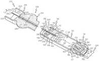
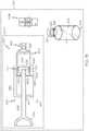
- FIG. 1is a perspective view of an exemplary fluid reservoir of a fluid infusion device and an exemplary system for filling the fluid reservoir of the fluid infusion device according to various teachings of the present disclosure
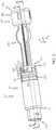
- FIG. 2is perspective view of the system of FIG. 1 assembled to fill the fluid reservoir of the fluid infusion device, with a pair of locking members of a transfer guard in a second position;
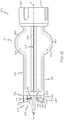
- FIG. 3is a cross-sectional view of the system of FIG. 2 , taken along line 3 - 3 of FIG. 2 , with a plunger portion of the fluid reservoir shown in a first position;
- FIG. 3Ais a cross-sectional view of the system of FIG. 2 , taken along line 3 - 3 of FIG. 2 , with the plunger portion shown in a second position;
- FIG. 4is a detail cross-sectional view of a portion of the fluid reservoir, taken from 4 of FIG. 3 ;
- FIG. 4Ais a detail cross-sectional end view of the portion of the fluid reservoir of FIG. 4 , which illustrates an annular trap defined about a perimeter of an end wall of the fluid reservoir;
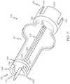
- FIG. 5is an expanded cross-sectional view of the system of FIG. 2 , taken along line 5 - 5 of FIG. 2 ;
- FIG. 6is an expanded view of the fluid reservoir and the transfer guard in according to the various teachings of the present disclosure
- FIG. 7is a rear perspective view of the plunger portion of the fluid reservoir of FIG. 1 , in which a stopper is coupled to an interface;
- FIG. 8is a first end view of the interface of the fluid reservoir of FIG. 1 ;
- FIG. 9is a side view of the interface of the fluid reservoir of FIG. 1 ;
- FIG. 10is a second end view of the interface of the fluid reservoir of FIG. 1 ;
- FIG. 11is a perspective view of the transfer guard of the system of FIG. 1 ;
- FIG. 12is an environmental schematic view that illustrates a second piercing member of the transfer guard coupled to the stopper of the fluid reservoir to fill the fluid reservoir with fluid;
- FIG. 13is a side view of the transfer guard of the system of FIG. 1 ;
- FIG. 14is perspective view of the system of FIG. 1 assembled to fill the fluid reservoir of the fluid infusion device, with the pair of locking members of the transfer guard in a first position;
- FIG. 15is a perspective view of another exemplary fluid reservoir of a fluid infusion device and another exemplary system for filling the fluid reservoir of the fluid infusion device according to various teachings of the present disclosure.
- the term “axial”refers to a direction that is generally parallel to or coincident with an axis of rotation, axis of symmetry, or centerline of a component or components.
- the “axial” directionmay refer to the direction that generally extends in parallel to the centerline between the opposite ends or faces.
- the term “axial”may be utilized with respect to components that are not cylindrical (or otherwise radially symmetric).
- the “axial” direction for a rectangular housing containing a rotating shaftmay be viewed as a direction that is generally parallel to or coincident with the rotational axis of the shaft.
- the term “radially” as used hereinmay refer to a direction or a relationship of components with respect to a line extending outward from a shared centerline, axis, or similar reference, for example in a plane of a cylinder or disc that is perpendicular to the centerline or axis.
- componentsmay be viewed as “radially” aligned even though one or both of the components may not be cylindrical (or otherwise radially symmetric).
- the terms “axial” and “radial” (and any derivatives)may encompass directional relationships that are other than precisely aligned with (e.g., oblique to) the true axial and radial dimensions, provided the relationship is predominately in the respective nominal axial or radial direction.
- the term “transverse”denotes an axis that crosses another axis at an angle such that the axis and the other axis are neither substantially perpendicular nor substantially parallel.
- the following descriptionrelates to a fluid infusion device of the type used to treat a medical condition of a user.
- the infusion devicecan be used for infusing fluid into the body of a user.
- the non-limiting examples described belowrelate to a medical device used to treat diabetes (more specifically, an insulin pump), although embodiments of the disclosed subject matter are not so limited.
- the infused medication fluidis insulin in certain embodiments.
- many other fluidsmay be administered through infusion such as, but not limited to, disease treatments, drugs to treat pulmonary hypertension, iron chelation drugs, pain medications, anti-cancer treatments, medications, vitamins, hormones, or the like.
- infusion pumps and/or related pump drive systems used to administer insulin and other medicationsmay be of the type described in, but not limited to: U.S. Patent Publication Nos. 2009/0299290 and 2008/0269687; U.S. Pat. Nos.
- FIG. 1is a perspective view of an exemplary embodiment of a fluid transfer system or system 100 for filling a fluid reservoir 102 of a fluid infusion device 104 .
- the system 100includes the fluid reservoir 102 of the fluid infusion device 104 , a transfer device or guard 106 and a vial 108 .
- One or more components of the system 100can be packaged together in suitable packaging for use as a kit by a consumer or user.
- the system 100enables the user to fill the fluid reservoir 102 of the fluid infusion device 104 with all or a portion of the contents of the vial 108 while reducing a risk of wetting one or more vent ports associated with the infusion set coupled to the fluid reservoir 102 and while reducing an amount of trapped air or “bubbles” that exit the fluid reservoir 102 , as will be discussed in greater detail herein.
- the fluid infusion device 104may be any fluid infusion device known in the art, and thus, the fluid infusion device 104 will not be discussed in great detail herein.
- the fluid infusion device 104is an insulin infusion device, such as the MiniMed Paradigm® REAL-Time RevelTM Insulin Pump, MiniMed 630G Insulin Pump or MiniMed 670G Insulin Pump, each commercially available from Medtronic MiniMed, Inc. of Northridge, Calif.
- the fluid infusion device 104is designed to be carried or worn by the patient.
- the fluid infusion device 104may leverage a number of conventional features, components, elements, and characteristics described in U.S. Pat. Nos. 6,485,465 and 7,621,893, the relevant content of which is incorporated by reference herein.
- the fluid reservoir 102is removably coupled to the fluid infusion device 104 .
- a partial cut-away view of the fluid reservoir 102is shown coupled to the transfer guard 106 .
- the fluid reservoir 102includes a first portion or barrel portion 110 and a second portion or plunger portion 112 .
- the barrel portion 110includes a first end 114 , a second end 116 and a fluid chamber or reservoir 118 defined between the first end 114 and the second end 116 .
- the barrel portion 110may be composed of a biocompatible polymer, and may be injection molded, etc.
- the first end 114 of the barrel portion 110includes a delivery port 120 , a coupling flange 122 and one or more bubble retaining features 124 .
- the delivery port 120 and the coupling flange 122cooperate to couple the fluid reservoir 102 to a set connector of an infusion set for establishing a fluid flow path out of the fluid reservoir 102 .
- the set connector and infusion setcomprise the Sure-T Paradigm® Infusion Set, which is commercially available from Medtronic MiniMed, Inc. of Northridge, Calif.
- the delivery port 120 and the coupling flange 122are defined on a first side 125 of an end wall 127 at the first end 114
- the bubble retaining features 124are defined on a second side 129 of the end wall 127 .
- the first side 125is generally opposite the second side 129
- the end wall 127defines a first terminal end of the reservoir 118 .
- the delivery port 120establishes a fluid flow path from the reservoir 118 .
- the delivery port 120is substantially cylindrical, and includes an exterior surface 126 and an interior bore 128 .
- the exterior surface 126may also define a swaged flange 130 , which aids in retaining the septum 136 within the delivery port 120 .
- the interior bore 128includes a septum chamber 132 and a needle passage 134 .
- the septum chamber 132is defined at a first end of the interior bore 128 and is surrounded by the flange 130 , which encloses a portion of the first end of the interior bore 128 , thereby enclosing a portion of the septum chamber 132 .
- the flange 130extends radially inward about a perimeter of the septum chamber 132 to retain a septum 136 within the septum chamber 132 .
- the septum chamber 132receives the septum 136 , which serves to prevent the ingress and egress of fluids out of the reservoir 118 .
- the septum 136is pierceable with a piercing member of the set connector (not shown) to enable fluid flow out of the reservoir 118 .
- the piercing memberis received through the needle passage 134 .
- the needle passage 134extends from the septum chamber 132 to the reservoir 118 , and receives the piercing member to enable fluid communication between the reservoir 118 and the infusion set (not shown).
- the needle passage 134may include tapered sidewalls to assist in forming the needle passage 134 and in retaining the septum 136 within the septum chamber 132 .
- the coupling flange 122substantially surrounds or circumscribes the delivery port 120 .
- the coupling flange 122includes one or more projections 140 , which are defined on an exterior surface of the delivery port 120 .
- the projections 140generally extend outwardly from the exterior surface, and cooperate with the set connector of the infusion set to securely couple the infusion set to the fluid reservoir 102 . It will be understood that the use of projections 140 is merely exemplary, as any engagement feature may be defined on the coupling flange 122 that cooperates with the set connector.
- the bubble retaining features 124are defined on the end wall 127 of the first end 114 .
- the bubble retaining features 124are disposed within the reservoir 118 .
- the bubble retaining features 124include the second side 129 of the end wall 127 and an annular trap 142 .
- the shape of the second side 129guides trapped air or “bubbles” within the fluid contained within the reservoir 118 to the trap 142 due to the buoyancy of the trapped air.
- the second side 129has a surface 144 that extends from an inner end 146 to an outer end 148 .
- the surface 144is an inclined or ramp surface, and is generally angled relative to the end wall 127 such that the “bubble” in the reservoir 118 may be guided by the surface 144 to the trap 142 due to the buoyancy of the “bubble” within the reservoir 118 .
- the surface 144extends along an axis A that has a negative slope relative to an axis A 2 defined through the end wall 127 , with the axis A 2 substantially perpendicular to a longitudinal axis L of the fluid reservoir 102 .
- the axis Ais generally transverse to or oblique to the longitudinal axis L.
- an angle ⁇ defined between the axis A and the axis A 2is about 15 to about 45 degrees.
- the surface 144defines a ramp having a positive slope in a direction of fluid flow out of the delivery port 120 of the fluid reservoir 102 . It should be noted that while the surface 144 is illustrated herein as extending substantially along a line in cross-section, the surface 144 may be contoured and may be substantially convex, if desired.
- the trap 142is an annular groove or recess defined about a perimeter of the end wall 127 within the reservoir 118 , as shown in FIG. 4A .
- the trap 142may have a substantially U-shaped cross-section, and may include a sharp corner 142 ′ at the transition from the outer end 148 of the surface 144 , which aids in retaining any “bubbles” within the trap 142 , and thus, the reservoir 118 . It will be understood, however; that the trap 142 may have any desired cross-sectional shape.
- the second end 116 of the fluid reservoir 102is substantially circumferentially open, and cooperates with the stopper 150 .
- the reservoir 118is defined between the first end 114 and the second end 116 .
- the reservoir 118is fillable with a fluid F from the vial 108 ( FIG. 1 ) using the transfer guard 106 .
- the reservoir 118is fillable with insulin from the vial 108 , but the reservoir 118 can be fillable with any suitable liquid.
- the plunger portion 112is received within the second end 116 of the fluid reservoir 102 and is movable by a drive system of the fluid infusion device 104 within the reservoir 118 to dispense fluid from the reservoir 118 through the set connector (not shown).
- the plunger portion 112includes a stopper 150 and an interface 152 .
- the interface 152is coupled to the stopper 150 , and cooperates with the transfer guard 106 to enable the filling of the reservoir 118 and to enable the movement of the plunger portion 112 upon application of a force from a drive system of the fluid infusion device 104 .
- the interface 152also provides a rigid contact point for the drive system associated with the fluid infusion device 104 .
- the stopper 150is composed of a biocompatible elastomeric material, such as a silicone.
- the stopper 150may be molded, cast or formed with any suitable technique.
- the stopper 150is integrally formed or is a one-piece monolithic component.
- the stopper 150is substantially symmetric about a central axis C of the stopper 150 .
- the stopper 150has a body that includes a first stopper end 154 , a second stopper end 156 , a sidewall 158 and a central slit 160 .
- the stopper 150is sized and shaped to be received within the second end 116 of the reservoir 118 such that the sidewall 158 forms a seal with a wall 118 ′ of the reservoir 118 .
- the stopper 150is generally movable within the reservoir 118 from the second end 116 ( FIG. 3 ) to the first end 114 ( FIG. 3A ) to dispense fluid out of the reservoir 118 via the delivery port 120 and from the first end 114 ( FIG. 3A ) to the second end 116 ( FIG. 3 ) to fill the reservoir 118 with the fluid F from the vial 108 ( FIG. 1 ).
- the first stopper end 154is opposite the second stopper end 156 , and faces the first end 114 of the reservoir 118 when the stopper 150 is received within the reservoir 118 .
- the first stopper end 154includes a first stopper surface 162 and a lip 163 .
- the first stopper surface 162has a shape or contour that corresponds to the shape of the second side 129 of the end wall 127 .
- the contour of the first stopper surface 162enables the first stopper surface 162 to be positioned against and mate with the end wall 127 to empty the fluid F from the reservoir 118 ; and to be positioned against and mate with the end wall 127 to enable the filling of the reservoir 118 with the fluid F, as shown in FIG. 3A .
- the first stopper surface 162may extend from a first inner stopper end 164 to a first outer stopper end 166 along an axis A 3 in cross-section, and may comprise an inclined surface or a ramp.
- the axis A 3may be transverse to or oblique to an axis A 4 defined through the cross-section of the stopper 150 near the first stopper end 154 .
- the axis A 4is substantially perpendicular to the central axis C of the stopper 150 .
- An angle ⁇may be defined between the axis A 3 and the axis A 4 . In one example, the angle ⁇ may be about 15 to about 45 degrees.
- the first stopper surface 162has a positive slope. It should be noted that while the first stopper surface 162 is illustrated herein as extending substantially along a line, the first stopper surface 162 may be contoured and may be substantially concave, if desired.
- the lip 163projects axially from the first stopper surface 162 about a perimeter of the first stopper surface 162 .
- the lip 163is generally sized to be received within the trap 142 when the stopper 150 is adjacent to the second side 129 of the end wall 127 .
- the second stopper end 156couples the stopper 150 to the interface 152 .
- the second stopper end 156includes a second stopper end surface 170 and a projection 172 .
- the second stopper end surface 170is substantially planar. In this example, the second stopper end surface 170 extends radially from the projection 172 to the perimeter of the second stopper end 156 .
- the projection 172is defined about the central axis C, and includes a base 174 and a flange 176 .
- the base 174is coupled to the second stopper end surface 170 , and extends axially away from the second stopper end surface 170 .
- the base 174extends for a distance D, which is sized and selected to enable the interface 152 to be positioned about the base 174 to couple the interface 152 to the base 174 .
- the base 174is generally cylindrical; however, the base 174 may have any desired shape for coupling to the interface 152 .
- the flange 176is coupled to the base 174 .
- the flange 176extends radially outward from the base 174 to retain the interface 152 .
- the flange 176may also be received at least partially within a portion of the transfer guard 106 to aid in coupling the transfer guard 106 to the plunger portion 112 .
- the sidewall 158extends circumferentially about the stopper 150 from the first stopper end 154 to the second stopper end 156 .
- the sidewall 158includes a first sealing surface or projection 180 and a second sealing surface or projection 182 .
- Each of the first sealing projection 180 and the second sealing projection 182may extend radially outward from the sidewall 158 a predetermined distance to engage the wall 118 ′ of the reservoir 118 .
- the first sealing projection 180 and the second sealing projection 182cooperate to prevent or inhibit fluid exiting the reservoir 118 about the stopper 150 .
- a side of the lip 163 opposite the first stopper surface 162may form part of the first sealing projection 180 , such that the first sealing projection 180 may extend over a greater circumferential area of the stopper 150 than the second sealing projection 182 .
- the central slit 160is defined through the body of the stopper 150 such that a portion of the transfer guard 106 may be inserted through the stopper 150 to fill the reservoir 118 with fluid.
- the stopper 150is pre-slit during manufacturing of the stopper 150 , via a cutting tool or the like, to enable the portion of the transfer guard 106 to be inserted through the stopper 150 .
- the central slit 160is configured such that once the portion of the transfer guard 106 is removed, the material of the stopper 150 substantially closes an opening provided by the central slit 160 to prevent the flow of fluid out of the stopper 150 .
- the stopper 150is pre-slit or at least partially cut along the central axis C to form the central slit 160 .
- the interface 152couples the plunger portion 112 to a drive system of the fluid infusion device 104 and the transfer guard 106 ( FIG. 1 ).
- the interface 152is rigid, and in one example is composed of a polymer, such as a polycarbonate blend, which is molded, cast, etc.
- the interface 152is coupled to the stopper 150 by molding the interface 152 about the base 174 , however, any suitable technique may be employed to couple the interface 152 to the stopper 150 .
- the interface 152includes an interface body 190 , one or more locking projections 192 and an interface bore 194 , which is defined through the interface body 190 .
- the interface bore 194receives the base 174 of the stopper 150 therethrough.
- the interface bore 194has a diameter that is sized to receive the base 174 to couple the interface 152 to the stopper 150 .
- the interface body 190is substantially annular, and is sized to be received around the base 174 of the stopper 150 to couple the interface 152 to the stopper 150 .
- the one or more locking projections 192extend outwardly from the interface body 190 , and couple the transfer guard 106 to the plunger portion 112 .
- the one or more locking projections 192are a pair of or two projections 192 ′, 192 ′′, which cooperate with a portion of the transfer guard 106 to couple the transfer guard 106 to the interface 152 .
- the locking projections 192 ′, 192 ′′each extend radially outward and axially along the interface body 190 .
- the locking projections 192 ′, 192 ′′are substantially opposed or opposite each other about the perimeter or circumference of the interface body 190 .
- the locking projections 192 ′, 192 ′′each include a first projection end 196 substantially opposite a second projection end 198 .
- the first projection end 196 of each of the locking projections 192 ′, 192 ′′is shown.
- the first projection end 196includes a first ramp surface 200 , a first ledge surface 202 and a first flange 204 .
- the first ramp surface 200cooperates with a portion of the transfer guard 106 to enable the coupling and uncoupling of the transfer guard 106 from the plunger portion 112 .
- the first ramp surface 200extends along an axis A 1 , which is substantially transverse or oblique to a line L 1 that lies along a plane defined by the second projection end 198 .
- the first ramp surface 200is at an angle ⁇ of about 5 to about 20 degrees relative to the second projection end 198 . It should be noted that the first ramp surface 200 need not extend along a line in cross-section, but rather, may be contoured or curved, depending upon the force requirements necessary for the coupling and uncoupling of the transfer guard 106 .
- the first ramp surface 200extends downward from a first ramp end 200 ′ to a second ramp end 200 ′′.
- the first ramp end 200 ′is a first terminal end of each of the respective locking projections 192 ′, 192 ′′ about the perimeter or circumference of the interface body 190 .
- the second ramp end 200 ′′ends at a wall 206 , which forms a stop for the further advancement of the portion of the transfer guard 106 .
- a radius Ris defined between the second ramp end 200 ′′ and the wall 206 .
- the wall 206transitions the first projection end 196 to the first ledge surface 202 .
- the first ledge surface 202is substantially planar or flat, and extends from the wall 206 to the first flange 204 .
- the first ledge surface 202reduces a mass savings by reducing a thickness of the locking projections 192 ′, 192 ′′.
- the first flange 204extends from the first ledge surface 202 .
- the first flange 204is defined so as to be contiguous with the interface body 190 .
- the first flange 204may be substantially wedge-shaped, and the first flanges 204 may be defined about the interface body 190 to substantially opposite each other about the perimeter or circumference of the interface body 190 .
- the first flanges 204each define a second terminal end of the respective locking projections 192 ′, 192 ′′ about the perimeter or circumference of the interface body 190 .
- the first flange 204 of the locking projection 192 ′is spaced apart from the first ramp end 200 ′ of the locking projection 192 ′′, and the first flange 204 of the locking projection 192 ′′ is spaced apart from the first ramp end 200 ′ of the locking projection 192 ′.
- the first flanges 204contact the second stopper end surface 170 and assist in transferring force from the drive system of the fluid infusion device 104 ( FIG. 1 ) to the stopper 150 .
- the second projection end 198 of each of the locking projections 192 ′, 192 ′′is shown.
- the second projection end 198is planar, and a counterbore 208 is defined between the opposing second projection ends 198 .
- the counterbore 208is sized and shaped to receive the flange 176 of the stopper 150 , such that the flange 176 of the stopper 150 is coplanar with the second projection ends 198 .
- the flange 176is received within the counterbore 208 such that the flange 176 is coupled to or contacts a surface 190 ′ of the interface body 190 .
- the second projection ends 198provide a rigid contact surface for the drive system of the fluid infusion device 104 ( FIG. 1 ) such that the application of a drive force to the second projection ends 198 assists in moving the stopper 150 within the second end 116 of the barrel portion 110 .
- the transfer guard 106is removably coupled to the fluid reservoir 102 to enable the fluid reservoir 102 to be filled with the fluid F from the vial 108 ( FIG. 1 ). With reference to FIG. 3 , the transfer guard 106 is coupled to the fluid reservoir 102 and the vial 108 in a first position, and may be at least partially received within the second end 116 of the fluid reservoir 102 .
- the transfer guard 106can be composed of any suitable material, such as a biocompatible polymer, for example, a polycarbonate blend, and may be injection molded, cast, etc.
- the transfer guard 106includes a first end 210 and a second end 212 , which can be interconnected via a body 214 .
- the first end 210includes a receiving portion 216 and a first piercing member 218 .
- the receiving portion 216receives a portion of the vial 108 to couple the vial 108 to the transfer guard 106 .
- the receiving portion 216is illustrated herein as substantially U-shaped in cross-section; however, the receiving portion 216 can have any suitable shape to mate with a portion of the vial 108 .
- the receiving portion 216includes one or more projections 220 , which are coupled to and extend outwardly from a base 222 .
- the projections 220are spaced apart about a perimeter of the base 222 so as to define one or more apertures 224 .
- the apertures 224enable a user to visually ensure the vial 108 is properly coupled to the receiving portion 216 and also enable the user to grip the vial 108 through the apertures 224 .
- the projections 220extend upwardly from the base 222 so as to extend parallel to a longitudinal axis L 2 of the transfer guard 106 . The projections 220 cooperate to couple the portion of the vial 108 to the base 222 , and thus, the first end 210 of the transfer guard 106 .
- the base 222is substantially planar, and the projections 220 extend outwardly from a surface 222 a of the base 222 . Generally, the projections 220 extend outwardly from a perimeter of the base 222 , however, the projections 220 can extend from the base 222 at any desired location based on a circumference or perimeter of a flange 226 of the vial 108 .
- the base 222also defines a bore 228 .
- the bore 228is sized and shaped to receive the first piercing member 218 therethrough.
- the first piercing member 218is received through the bore 228 of the base 222 .
- the first piercing member 218generally extends along the longitudinal axis L 2 of the transfer guard 106 .
- the first piercing member 218may be coupled to the bore 228 through any suitable technique, such as press-fit, adhesive bonding, ultrasonic welding, etc.
- the first piercing member 218is coupled to the bore 228 by an adhesive bond.
- the first piercing member 218comprises a hollow needle or cannula to enable fluid to flow through the first piercing member 218 .
- the first piercing member 218is composed of a metal or metal alloy, for example, a stainless steel.
- the first piercing member 218has a first piercing tip 230 at a first end 232 and a second conduit tip 234 at a second end 236 , with the second end 236 opposite the first end 232 .
- the first piercing tip 230establishes a fluid flow path out of the vial 108 and through the body 214 of the transfer guard 106 .
- the projections 220 of the receiving portion 216generally extend outwardly from the base 222 for a distance greater than the first piercing tip 230 to act as a guard for the first piercing tip 230 .
- the second conduit tip 234fluidly couples the body 214 to a portion of the second end 212 of the transfer guard 106 .
- the second end 212 of the transfer guard 106couples the transfer guard 106 to the interface 152 of the plunger portion 112 of the fluid reservoir 102 .
- the second end 212 of the transfer guard 106 and the interface 152cooperate such that the transfer guard 106 may be used only a single time to fill the fluid reservoir 102 with the fluid from the vial 108 .
- the transfer guard 106is a consumable component.
- the second end 212includes a second base 240 , a second piercing member 242 and one or more locking members 244 .
- the second base 240is substantially circular, and includes a first side 246 , a second side 248 opposite the first side 246 and defines a second bore 250 ( FIG. 3 ) that extends through the first side 246 and the second side 248 .
- the first side 246 of the second base 240is coupled to the body 214
- the second side 246 of the second base 240is coupled to the one or more locking members 244 .
- the second bore 250receives the second conduit tip 234 therethrough.
- the second piercing member 242is coupled to the second side 248 of the second base 240 so as to extend outwardly from the second side 248 about a circumference of the second bore 250 .
- the second piercing member 242has a length, which is sized to enable the second piercing member 242 to be received within the central slit 160 of the stopper 150 such that at least a portion of the second piercing member 242 is received within the reservoir 118 when the transfer guard 106 is coupled to the interface 152 to fill the reservoir 118 .
- the second piercing member 242generally extends along the longitudinal axis L 2 of the transfer guard 106 .
- the second piercing member 242is generally composed of a biocompatible polymer, such as a polycarbonate blend, and may be integrally formed with the transfer guard 106 or coupled to the transfer guard 106 in a processing step, via ultrasonic welding, for example.
- the second piercing member 242is hollow or defines a central bore 242 ′.
- the central bore 242 ′receives the second conduit tip 234 to define a fluid flow path through the transfer guard 106 . As shown in FIG.
- the second piercing member 242defines a cross-bore 252 , which is defined so as to extend through the second piercing member 242 along an axis that is substantially perpendicular to the central axis C of the stopper 150 .
- the cross-bore 252enables fluid exit the second piercing member 242 into the reservoir 118 , and thereby, fill the reservoir 118 .
- the use of a cross-bore 252 , the second piercing member 242 composed of a polymeric material and the first inner stopper end 164 having the positive slope in cross-sectionfurther assists in reducing an amount of trapped air or “bubbles” that may be introduced during the filling of the reservoir 118 as the concavity defined by the first inner stopper end 164 , which is adjacent to the cross-bore 252 , may inhibit the trapping of air between the second piercing member 242 and the first stopper end 154 during the filling of the reservoir 118 .
- the one or more locking members 244are coupled to the second side 248 of the second base 240 .
- the one or more locking members 244are a pair of or two locking members 244 ′, 244 ′′.
- Each of the locking members 244 ′, 244 ′′cooperates with a respective one of the locking projections 192 ′, 192 ′′, to removably couple the transfer guard 106 to the interface 152 of the plunger portion 112 .
- the locking members 244 ′, 244 ′′are generally opposite or opposed from each other about a perimeter or circumference of the second base 240 , and are each spaced apart from the second piercing member 242 .
- the locking members 244 ′, 244 ′′are spaced apart from or offset from the longitudinal axis L 2 of the transfer guard 106 .
- each of the locking members 244 ′, 244 ′′include a stem 260 and a locking arm 262 .
- Each stem 260has a first stem end 264 opposite a second stem end 266 .
- the first stem end 264is coupled to the second surface 248 of the second base 240
- the second stem end 266is coupled to the locking arm 262 .
- the stem 260generally extends outwardly along an axis that is substantially parallel to the longitudinal axis L 2 of the transfer guard 106 .
- the stem 260extends for a length that enables the locking arm 262 to engage with the first ramp surfaces 200 of the respective locking projections 192 ′, 192 ′′.
- Each locking arm 262is coupled to the second stem end 266 .
- the locking arms 262extend outwardly from the second stem end 266 so as to at least partially follow the perimeter or circumference of the second base 240 . Stated another way, the locking arms 262 are arcuate, and extend outward from the second stem end 266 so as to be spaced a distance apart from the second surface 248 of the second base 240 .
- the locking arms 262each include a notch 268 and a second ramp surface 270 .
- the notch 268 and the second ramp surface 270are defined on a first arm side 272 , which is opposite a second arm side 274 .
- the notch 268is defined at a first end 262 ′ of the locking arms 262
- the second ramp surface 270extends from the notch 268 to a second end 262 ′′ of the locking arms 262 .
- the notch 268is defined at the first end 262 ′ to enable the locking arms 262 to move between a first position and a second position.
- the notch 268is a groove, which reduces a thickness of each of the locking arms 262 at the first end 262 ′ to provide each of the locking arms 262 with flexibility to move the locking members 244 ′, 244 ′′ between the first position and the second position.
- the locking members 244 ′, 244 ′′are in the first position when the locking arms 262 are unbiased or in a neutral, unflexed position, as is shown in FIG. 13 .
- each of the locking arms 262is spaced a first distance D 1 from the second surface 248 of the second base 240 .
- the locking members 244 ′, 244 ′′are flexed, biased or expanded outwardly away from the second surface 248 such that the second end 262 ′′ of each of the locking arms 262 is spaced a second distance D 2 ( FIG. 2 ) away from the second surface 248 .
- the second distance D 2is generally greater than the first distance D 1 such that when the locking arms 262 are disengaged with the respective locking projections 192 ′, 192 ′′ of the interface 152 , the locking arms 262 return to the first position and substantially prevent the reassembly of the transfer guard 106 to the interface 152 .
- the locking members 244 ′, 244 ′′cooperate with the locking projections 192 ′, 192 ′′ to substantially prevent the reuse of the transfer guard 106 .
- the second ramp surface 270is defined on the first arm side 272 of the locking arm 262 so as to extend from the notch 268 to the second end 262 ′′.
- the second ramp surface 270has an incline that mates with the first ramp surface 200 of the respective locking projections 192 ′, 192 ′′ such that each of the locking arms 262 may be coupled to the locking projections 192 ′, 192 ′′ to enable a filling of the reservoir 118 .
- the second ramp surface 270extends along an axis A 4 , which is substantially transverse or oblique to a line L 3 that lies along a plane defined through the locking arm 262 .
- the second ramp surface 270is at an angle ⁇ of about negative 5 to about negative 20 degrees relative to the second projection end 198 .
- the second ramp surface 270need not extend along a line, but rather, may be contoured or curved, depending upon the force requirements necessary for the coupling and uncoupling of the transfer guard 106 from the interface 152 .
- the use of the first ramp surface 200 and the second ramp surface 270is merely exemplary, as any suitable cooperating engagement surfaces may be defined, such as mating threads, etc.
- the body 214 of the transfer guard 106can fluidly interconnect or couple the fluid reservoir 102 and the vial 108 to each other.
- the body 214may be elongated along the longitudinal axis L 2 , however, the body 214 can have any desired shape to fluidly interconnect or couple the fluid reservoir 102 and the vial 108 together.
- the body 214includes a first member 280 , a second member 282 and defines a central body bore 286 between the first member 280 and the second member 282 .
- the first member 280 and the second member 282are substantially planar, but may include a thickened ridge 280 ′, 282 ′ about a perimeter of the respective first member 280 and second member 282 to facilitate a user's handling of the transfer guard 106 .
- the first member 280 and the second member 282are substantially symmetric about a plane defined by the longitudinal axis L 2 .
- the first member 280 and the second member 282each include a graspable portion 284 , which projects outwardly a reminder of the first member 280 and the second member 282 .
- the graspable portion 284enables a user to manipulate the transfer guard 106 , which aids in coupling the vial 108 to the transfer guard 106 .
- the central body bore 286is defined between the first member 280 and the second member 282 .
- the central body bore 286extends along the longitudinal axis L 2 , and is sized to enable the first piercing member 218 to pass through the transfer guard 106 from the base 222 to the second base 240 .
- the central body bore 286is generally in communication with the bore 228 of the base 222 and the second bore 250 of the second base 240 .
- the vial 108can comprise any suitable vial for storing a fluid F.
- the vial 108stores insulin, and defines a chamber 300 for storing the fluid.
- the chamber 300narrows or necks to the flange 226 .
- the flange 226may be coupled to the first end 210 of the transfer guard 106 .
- the flange 226defines a vial passageway 302 .
- the vial passageway 302provides a fluid flow path out of the chamber 300 , and is closed with a septum 304 .
- the septum 304is disposed in the flange 226 and serves to prevent the ingress and egress of fluids out of the chamber 300 of the vial 108 .
- the septum 304is pierceable with the first piercing member 218 to enable fluid flow out of the vial 108 .
- the stopper 150may be pre-slit to define the central slit 160 .
- the interface 152is coupled about the base 174 of the stopper 150 such that the flange 176 is received within the counterbore 208 ( FIG. 7 ).
- a suitable toolsuch as a spreading tool, may be coupled to the second end 212 of the transfer guard 106 to move the locking members 244 ′, 244 ′′ from the first position to the second position.
- the locking members 244 ′, 244 ′′are flexed, biased or expanded outward away from the second surface 248 such that the locking arms 262 are spaced from the second surface 248 by the second distance D 2 ( FIG. 2 ).
- the transfer guard 106is coupled to the interface 152 by rotating the transfer guard 106 until the second ramp surfaces 270 substantially contact the wall 206 of the locking projections 192 ′, 192 ′′.
- the coupling of the transfer guard 106 to the interface 152advances the second piercing member 242 through the central slit 160 until the second piercing member 242 extends outwardly from the first stopper surface 162 .
- the stopper 150With the transfer guard 106 coupled to the interface 152 , and the interface 152 coupled to the stopper 150 , the stopper 150 is inserted into the barrel portion 110 through the open circumference of the barrel portion 110 at the second end 116 . Generally, the stopper 150 is inserted into the barrel portion 110 until the stopper 150 contacts or is adjacent to the second side 129 of the end wall 127 ( FIG. 3A ). The second piercing member 242 may pass into the needle passage 134 , but does not pierce the septum 136 . By advancing the stopper 150 coupled to the transfer guard 106 to the first end 114 of the barrel portion 110 , the movement of the stopper 150 from the first end 114 to the second end 116 ( FIG.
- the fluid reservoir 102 and the transfer guard 106may be packaged for the user such that the fluid reservoir 102 and the transfer guard 106 are coupled together, with the locking members 244 ′, 244 ′′ of the transfer guard 106 coupled to the locking projections 192 ′, 192 ′′ of the interface 152 .
- the fluid reservoir 102 and the vial 108may be packaged together such that the fluid transfer system 100 may form a kit to be used by a user to fill the fluid reservoir 102 .
- the usermay begin a filling operation.
- the usermay couple the vial 108 to the first end 210 of the transfer guard 106 such that the first piercing member 218 pierces the septum 304 of the vial 108 , and thereby establishes a fluid flow path from the vial 108 , through the first piercing member 218 and through the second piercing member 242 into the reservoir 118 , as shown in FIG. 2 .
- the usergrasps the graspable portion 284 and may apply a force F 2 to the transfer guard 106 to move the stopper 150 from the first end 114 of the barrel portion 110 (as shown in FIG. 3A ) to the second end 116 (as shown in FIG. 3 ).
- the movement of the stopper 150 from the first end 114 to the second end 116fills the reservoir 118 with the fluid F from the vial 108 via the fluid flow path defined by the first piercing member 218 and the second piercing member 242 of the transfer guard 106 ( FIG. 2 ).
- the fluid Fflows from the vial 108 through the first piercing member 218 and the second piercing member 242 , the fluid F exits into the reservoir 118 via the cross-bore 252 defined in the second piercing member 242 ( FIG. 12 ).
- the sideways flow path from the cross-bore 252may reduce an amount of air trapped between the second piercing member 242 and the stopper 150 .
- the second side 129guides any trapped air or “bubbles” along the surface 144 to the trap 142 .
- the trap 142may capture trapped air or “bubbles” and substantially eliminate trapped air or “bubbles” exiting the reservoir 118 via the delivery port 120 .
- the transfer guard 106is coupled to the stopper 150 , the risk of wetting vent ports associated with the infusion set coupled to the delivery port 120 is substantially eliminated.
- the reservoir 118is substantially filled with the fluid F.
- the usermay then uncouple the transfer guard 106 from the interface 152 .
- the usermay apply a torque T to the body 214 of the transfer guard 106 to rotate the transfer guard 106 relative to the interface 152 .
- the applied torque Tcauses the second ramp surface 270 of the locking arms 262 to move up the first ramp surface 200 of the locking projections 192 ′, 192 ′′ until the locking members 244 ′, 244 ′′ no longer contact the locking projections 192 ′, 192 ′′, as shown in FIG.
- the locking members 244 ′, 244 ′′move from the second position to the first position.
- the first distance D 1 between the second end 262 ′′ of each of the locking members 244 ′, 244 ′′is less than a distance or length D 3 of the second ramp end 200 ′′ of each of the first ramp surfaces 200 such that the locking members 244 ′, 244 ′′ cannot reengage with or be recoupled to the locking projections 192 ′, 192 ′′.
- the length D 3 of the second ramp end 200 ′′is greater than the first distance D 1 between the second end 262 ′′ and the second side 248 such that the transfer guard 106 cannot be reengaged with the interface 152 .
- the usermay not recouple or reconnect the transfer guard 106 to the interface 152 .
- the transfer guard 106may be removed from the second end 116 of the fluid reservoir 102 , and the central slit 160 of the stopper 150 may close due to the resilient material from which the stopper 150 is composed.
- the fluid reservoir 102may then be coupled to the fluid infusion device 104 .
- the fluid transfer system 100enables the filling of the fluid reservoir 102 while substantially eliminating the risk of wetting one or more vent ports associated with an infusion set that is coupled to the delivery port 120 as the fluid F is introduced to the fluid reservoir 102 at the second end 116 .
- an amount of air that enters the reservoir 118 and becomes trapped during the filling operationis reduced.
- any air or “bubbles” that may enter the reservoir 118 during the filling operationmay follow the ramp defined by the surface 144 of the second side 129 and become trapped in the trap 142 ( FIG. 4 ).
- the fluid reservoir 102By trapping the “bubbles” in the trap 142 , the fluid reservoir 102 substantially eliminates and prevents air from exiting the fluid reservoir 102 via the delivery port 120 . Further, the cooperation between the locking projections 192 ′, 192 ′′ of the interface 152 and the locking members 244 ′, 244 ′′ of the transfer guard 106 ensure that the user may only use the transfer guard 106 one time.
- the system 100enables the reservoir 118 to be filled with fluid from the vial 108 , for example, insulin, with little to no trapped air or “bubbles,” while inhibiting the reuse of the transfer guard 106 .
- the configuration of the fluid transfer system 100 as described hereinis not limited to the configuration shown in FIGS. 1-14 .
- a fluid transfer system 1000is shown.
- the fluid transfer system 1000is similar to the fluid transfer system 100 described with regard to FIGS. 1-14 , the same reference numerals will be used to denote the same features.
- the fluid transfer system 1000is for filling a fluid reservoir 1002 of the fluid infusion device 104 .
- the system 1000includes the fluid reservoir 1002 of the fluid infusion device 104 , a transfer device or guard 1006 , the vial 108 and a pull-rod 1008 .
- the transfer guard 1006may be commercially available from Medtronic MiniMed, Inc. of Northridge, Calif., and thus, will not be discussed in great detail herein.
- One or more components of the system 1000can be packaged together in suitable packaging for use as a kit by a consumer or user.
- the system 1000enables the user to fill the fluid reservoir 1002 of the fluid infusion device 104 with all or a portion of the contents of the vial 108 while reducing a risk of wetting one or more vent ports associated with the infusion set coupled to the fluid reservoir 1002 as will be discussed in greater detail herein.
- the fluid reservoir 1002includes a first portion or barrel portion 1010 and a second portion or plunger portion 1012 .
- the barrel portion 1010includes a first end 1014 , a second end 1016 and a reservoir 1018 defined between the first end 1014 and the second end 1016 .
- the first end 1014defines a fluid flow path out of the reservoir 1018 when coupled to a set connector of an infusion set, and generally includes a septum (not shown).
- the second end 1016is circumferentially open, and receives the plunger portion 1012 .
- the plunger portion 1012is movable or slidable within the reservoir 1018 to fill the reservoir 1018 with fluid or advance fluid out of the reservoir 1018 via the fluid flow path defined at the first end 1014 .
- the plunger portion 1012includes a stopper 1020 .
- the stopper 1020is coupled to an interior wall 1018 ′ of the reservoir 1018 and is movable relative to the reservoir 1018 by a drive system of the fluid infusion device 104 to advance fluid out of the reservoir 1018 .
- the stopper 1020may also be coupled to the pull-rod 1008 to draw fluid into the reservoir 1018 during a filling operation.
- the stopper 1020includes a coupling feature 1022 , which is defined on a first side 1020 ′ of the stopper 1020 .
- the first side 1020 ′ of the stopper 1020is substantially opposite a second side 1020 ′′ of the stopper 1020 that disposed within the reservoir 1018 .
- the coupling feature 1022is any suitable coupling feature, such as a threaded bore, a keyed interface, etc., which couples the stopper 1020 to the pull-rod 1008 .
- the stopper 1020may be moved relative to the barrel portion 1010 to fill the reservoir 1018 with the fluid F from the vial 108 .
- the pull-rod 1008generally includes a rod 1030 and a sleeve 1032 .
- the rod 1030has a first end 1034 coupled to the stopper 1020 , and a second, opposite end 1036 .
- the first end 1034includes a second coupling feature 1038 that cooperates with the coupling feature 1022 of the stopper 1020 to couple the rod 1030 to the stopper 1020 .
- the second coupling feature 1038comprises a plurality of threads, which matingly engage with the threaded bore of the coupling feature 1022 to couple the stopper 1020 to the rod 1030 .
- the second end 1036 of the rod 1030comprises a graspable portion, which may be manipulated by a user to move the stopper 1020 and thereby fill the reservoir 1018 .
- the sleeve 1032defines an opening 1040 , which is sized and shaped to form a tight fit with reduced clearance about the perimeter or circumference of the plunger portion 1012 of the fluid reservoir 1002 .
- the sleeve 1032may form an interference fit with the second end 1016 of the fluid reservoir 1002 .
- the sleeve 1032also defines a rod bore 1042 , which enables the rod 1030 to be movable relative to the sleeve 1032 .
- the sleeve 1032is positioned about the second end 1016 of the barrel portion 1010 .
- the rod 1030is advanced through the rod bore 1042 , and the second coupling feature 1038 is coupled to or engaged with the coupling feature 1022 of the stopper 1020 to couple the stopper 1020 to the rod 1030 .
- the transfer guard 1006is coupled to the first end 1014 of the barrel portion 1010 such that a piercing member of the transfer guard 1006 pierces the septum of the fluid reservoir 1002
- the vial 108is coupled to the transfer guard 1006 such that a piercing member of the transfer guard 1006 pierces the septum 304 of the vial 108 .
- the fluid transfer system 1000enables the filling of the fluid reservoir 1002 while substantially eliminating the risk of wetting one or more vent ports associated with an infusion set coupled to the delivery port by coupling the pull-rod 1008 to the stopper 1020 .
- the pull-rod 1008may not be in contact with the fluid, such as insulin, during the filling of the fluid reservoir 1002 , the pull-rod 1008 may be a durable component, such that the pull-rod 1008 may be used multiple times (i.e. reused) to fill the fluid reservoir 1002 . This may reduce a user's cost associated with filling the fluid reservoir 1002 .
Landscapes
- Health & Medical Sciences (AREA)
- Life Sciences & Earth Sciences (AREA)
- Veterinary Medicine (AREA)
- Public Health (AREA)
- General Health & Medical Sciences (AREA)
- Animal Behavior & Ethology (AREA)
- Biomedical Technology (AREA)
- Hematology (AREA)
- Heart & Thoracic Surgery (AREA)
- Anesthesiology (AREA)
- Engineering & Computer Science (AREA)
- Vascular Medicine (AREA)
- Pharmacology & Pharmacy (AREA)
- Emergency Medicine (AREA)
- Physics & Mathematics (AREA)
- Fluid Mechanics (AREA)
- Infusion, Injection, And Reservoir Apparatuses (AREA)
Abstract
Description
Claims (14)
Priority Applications (1)
| Application Number | Priority Date | Filing Date | Title |
|---|---|---|---|
| US15/419,932US10532165B2 (en) | 2017-01-30 | 2017-01-30 | Fluid reservoir and systems for filling a fluid reservoir of a fluid infusion device |
Applications Claiming Priority (1)
| Application Number | Priority Date | Filing Date | Title |
|---|---|---|---|
| US15/419,932US10532165B2 (en) | 2017-01-30 | 2017-01-30 | Fluid reservoir and systems for filling a fluid reservoir of a fluid infusion device |
Publications (2)
| Publication Number | Publication Date |
|---|---|
| US20180214630A1 US20180214630A1 (en) | 2018-08-02 |
| US10532165B2true US10532165B2 (en) | 2020-01-14 |
Family
ID=62977444
Family Applications (1)
| Application Number | Title | Priority Date | Filing Date |
|---|---|---|---|
| US15/419,932Active2037-08-23US10532165B2 (en) | 2017-01-30 | 2017-01-30 | Fluid reservoir and systems for filling a fluid reservoir of a fluid infusion device |
Country Status (1)
| Country | Link |
|---|---|
| US (1) | US10532165B2 (en) |
Citations (221)
| Publication number | Priority date | Publication date | Assignee | Title |
|---|---|---|---|---|
| US3631847A (en) | 1966-03-04 | 1972-01-04 | James C Hobbs | Method and apparatus for injecting fluid into the vascular system |
| US4212738A (en) | 1977-03-28 | 1980-07-15 | Akzo N.V. | Artificial kidney |
| US4270532A (en) | 1977-12-28 | 1981-06-02 | Siemens Aktiengesellschaft | Device for the pre-programmable infusion of liquids |
| US4282872A (en) | 1977-12-28 | 1981-08-11 | Siemens Aktiengesellschaft | Device for the pre-programmable infusion of liquids |
| US4373527A (en) | 1979-04-27 | 1983-02-15 | The Johns Hopkins University | Implantable, programmable medication infusion system |
| US4395259A (en) | 1980-09-22 | 1983-07-26 | Siemens Aktiengesellschaft | Device for the infusion of fluids into the human or animal body |
| US4433072A (en) | 1978-12-15 | 1984-02-21 | Hospal-Sodip, S.A. | Mixtures of polymers for medical use |
| US4443218A (en) | 1982-09-09 | 1984-04-17 | Infusaid Corporation | Programmable implantable infusate pump |
| US4494950A (en) | 1982-01-19 | 1985-01-22 | The Johns Hopkins University | Plural module medication delivery system |
| US4542532A (en) | 1984-03-09 | 1985-09-17 | Medtronic, Inc. | Dual-antenna transceiver |
| US4550731A (en) | 1984-03-07 | 1985-11-05 | Cordis Corporation | Acquisition circuit for cardiac pacer |
| US4559037A (en) | 1977-12-28 | 1985-12-17 | Siemens Aktiengesellschaft | Device for the pre-programmable infusion of liquids |
| US4562751A (en) | 1984-01-06 | 1986-01-07 | Nason Clyde K | Solenoid drive apparatus for an external infusion pump |
| US4671288A (en) | 1985-06-13 | 1987-06-09 | The Regents Of The University Of California | Electrochemical cell sensor for continuous short-term use in tissues and blood |
| US4678408A (en) | 1984-01-06 | 1987-07-07 | Pacesetter Infusion, Ltd. | Solenoid drive apparatus for an external infusion pump |
| US4685903A (en) | 1984-01-06 | 1987-08-11 | Pacesetter Infusion, Ltd. | External infusion pump apparatus |
| US4731051A (en) | 1979-04-27 | 1988-03-15 | The Johns Hopkins University | Programmable control means for providing safe and controlled medication infusion |
| US4731726A (en) | 1986-05-19 | 1988-03-15 | Healthware Corporation | Patient-operated glucose monitor and diabetes management system |
| US4781798A (en) | 1985-04-19 | 1988-11-01 | The Regents Of The University Of California | Transparent multi-oxygen sensor array and method of using same |
| US4803625A (en) | 1986-06-30 | 1989-02-07 | Buddy Systems, Inc. | Personal health monitor |
| US4809697A (en) | 1987-10-14 | 1989-03-07 | Siemens-Pacesetter, Inc. | Interactive programming and diagnostic system for use with implantable pacemaker |
| US4826810A (en) | 1983-12-16 | 1989-05-02 | Aoki Thomas T | System and method for treating animal body tissues to improve the dietary fuel processing capabilities thereof |
| EP0319268A2 (en) | 1987-12-04 | 1989-06-07 | IVAC MEDICAL SYSTEMS, Inc. | Clinical configuration of multimode medication infusion system |
| US4871351A (en) | 1984-09-28 | 1989-10-03 | Vladimir Feingold | Implantable medication infusion system |
| GB2218831A (en) | 1988-05-17 | 1989-11-22 | Mark John Newland | Personal medical apparatus |
| US4898578A (en) | 1988-01-26 | 1990-02-06 | Baxter International Inc. | Drug infusion system with calculator |
| US5003298A (en) | 1986-01-15 | 1991-03-26 | Karel Havel | Variable color digital display for emphasizing position of decimal point |
| US5011468A (en) | 1987-05-29 | 1991-04-30 | Retroperfusion Systems, Inc. | Retroperfusion and retroinfusion control apparatus, system and method |
| US5019974A (en) | 1987-05-01 | 1991-05-28 | Diva Medical Systems Bv | Diabetes management system and apparatus |
| US5050612A (en) | 1989-09-12 | 1991-09-24 | Matsumura Kenneth N | Device for computer-assisted monitoring of the body |
| US5078683A (en) | 1990-05-04 | 1992-01-07 | Block Medical, Inc. | Programmable infusion system |
| US5080653A (en) | 1990-04-16 | 1992-01-14 | Pacesetter Infusion, Ltd. | Infusion pump with dual position syringe locator |
| US5097122A (en) | 1990-04-16 | 1992-03-17 | Pacesetter Infusion, Ltd. | Medication infusion system having optical motion sensor to detect drive mechanism malfunction |
| US5100380A (en) | 1984-02-08 | 1992-03-31 | Abbott Laboratories | Remotely programmable infusion system |
| US5101814A (en) | 1989-08-11 | 1992-04-07 | Palti Yoram Prof | System for monitoring and controlling blood glucose |
| US5108819A (en) | 1990-02-14 | 1992-04-28 | Eli Lilly And Company | Thin film electrical component |
| US5153827A (en) | 1989-01-30 | 1992-10-06 | Omni-Flow, Inc. | An infusion management and pumping system having an alarm handling system |
| US5165407A (en) | 1990-04-19 | 1992-11-24 | The University Of Kansas | Implantable glucose sensor |
| US5247434A (en) | 1991-04-19 | 1993-09-21 | Althin Medical, Inc. | Method and apparatus for kidney dialysis |
| US5262305A (en) | 1991-03-04 | 1993-11-16 | E. Heller & Company | Interferant eliminating biosensors |
| US5262035A (en) | 1989-08-02 | 1993-11-16 | E. Heller And Company | Enzyme electrodes |
| US5264104A (en) | 1989-08-02 | 1993-11-23 | Gregg Brian A | Enzyme electrodes |
| US5264105A (en) | 1989-08-02 | 1993-11-23 | Gregg Brian A | Enzyme electrodes |
| US5284140A (en) | 1992-02-11 | 1994-02-08 | Eli Lilly And Company | Acrylic copolymer membranes for biosensors |
| US5299571A (en) | 1993-01-22 | 1994-04-05 | Eli Lilly And Company | Apparatus and method for implantation of sensors |
| US5307263A (en) | 1992-11-17 | 1994-04-26 | Raya Systems, Inc. | Modular microprocessor-based health monitoring system |
| US5320725A (en) | 1989-08-02 | 1994-06-14 | E. Heller & Company | Electrode and method for the detection of hydrogen peroxide |
| US5322063A (en) | 1991-10-04 | 1994-06-21 | Eli Lilly And Company | Hydrophilic polyurethane membranes for electrochemical glucose sensors |
| US5338157A (en) | 1992-09-09 | 1994-08-16 | Pharmacia Deltec, Inc. | Systems and methods for communicating with ambulatory medical devices such as drug delivery devices |
| US5341291A (en) | 1987-12-09 | 1994-08-23 | Arch Development Corporation | Portable medical interactive test selector having plug-in replaceable memory |
| US5339821A (en) | 1992-02-13 | 1994-08-23 | Seta Co., Ltd. | Home medical system and medical apparatus for use therewith |
| US5350411A (en) | 1993-06-28 | 1994-09-27 | Medtronic, Inc. | Pacemaker telemetry system |
| US5356786A (en) | 1991-03-04 | 1994-10-18 | E. Heller & Company | Interferant eliminating biosensor |
| US5357427A (en) | 1993-03-15 | 1994-10-18 | Digital Equipment Corporation | Remote monitoring of high-risk patients using artificial intelligence |
| US5364369A (en) | 1987-07-08 | 1994-11-15 | Reynolds David L | Syringe |
| US5368562A (en) | 1993-07-30 | 1994-11-29 | Pharmacia Deltec, Inc. | Systems and methods for operating ambulatory medical devices such as drug delivery devices |
| US5371687A (en) | 1992-11-20 | 1994-12-06 | Boehringer Mannheim Corporation | Glucose test data acquisition and management system |
| US5370622A (en) | 1994-04-28 | 1994-12-06 | Minimed Inc. | Proctective case for a medication infusion pump |
| US5376070A (en) | 1992-09-29 | 1994-12-27 | Minimed Inc. | Data transfer system for an infusion pump |
| US5391250A (en) | 1994-03-15 | 1995-02-21 | Minimed Inc. | Method of fabricating thin film sensors |
| US5390671A (en) | 1994-03-15 | 1995-02-21 | Minimed Inc. | Transcutaneous sensor insertion set |
| DE4329229A1 (en) | 1993-08-25 | 1995-03-09 | Meditech Medizintechnik Gmbh | Adaptive controlled pump control, in particular for adaptive patient-controlled analgesia (APCA) |
| US5411647A (en) | 1992-11-23 | 1995-05-02 | Eli Lilly And Company | Techniques to improve the performance of electrochemical sensors |
| US5482473A (en) | 1994-05-09 | 1996-01-09 | Minimed Inc. | Flex circuit connector |
| US5497772A (en) | 1993-11-19 | 1996-03-12 | Alfred E. Mann Foundation For Scientific Research | Glucose monitoring system |
| US5505709A (en) | 1994-09-15 | 1996-04-09 | Minimed, Inc., A Delaware Corporation | Mated infusion pump and syringe |
| WO1996020745A1 (en) | 1995-01-06 | 1996-07-11 | Abbott Laboratories | Medicinal fluid pump having multiple stored protocols |
| US5543326A (en) | 1994-03-04 | 1996-08-06 | Heller; Adam | Biosensor including chemically modified enzymes |
| US5569187A (en) | 1994-08-16 | 1996-10-29 | Texas Instruments Incorporated | Method and apparatus for wireless chemical supplying |
| US5569186A (en) | 1994-04-25 | 1996-10-29 | Minimed Inc. | Closed loop infusion pump system with removable glucose sensor |
| US5573506A (en) | 1994-11-25 | 1996-11-12 | Block Medical, Inc. | Remotely programmable infusion system |
| WO1996036389A1 (en) | 1995-05-15 | 1996-11-21 | Ivac Medical Systems, Inc. | Automated infusion system with dose rate calculator |
| WO1996037246A1 (en) | 1995-05-26 | 1996-11-28 | Minimed Inc. | Medication infusion device with blood glucose data input |
| US5582593A (en) | 1994-07-21 | 1996-12-10 | Hultman; Barry W. | Ambulatory medication delivery system |
| US5586553A (en) | 1995-02-16 | 1996-12-24 | Minimed Inc. | Transcutaneous sensor insertion set |
| US5593852A (en) | 1993-12-02 | 1997-01-14 | Heller; Adam | Subcutaneous glucose electrode |
| US5593390A (en) | 1994-03-09 | 1997-01-14 | Visionary Medical Products, Inc. | Medication delivery device with a microprocessor and characteristic monitor |
| US5594638A (en) | 1993-12-29 | 1997-01-14 | First Opinion Corporation | Computerized medical diagnostic system including re-enter function and sensitivity factors |
| US5609060A (en) | 1995-04-28 | 1997-03-11 | Dentsleeve Pty Limited | Multiple channel perfused manometry apparatus and a method of operation of such a device |
| US5626144A (en) | 1994-05-23 | 1997-05-06 | Enact Health Management Systems | System for monitoring and reporting medical measurements |
| US5630710A (en) | 1994-03-09 | 1997-05-20 | Baxter International Inc. | Ambulatory infusion pump |
| WO1997021456A1 (en) | 1995-12-12 | 1997-06-19 | The University Of Melbourne | Field programmable intravenous infusion system |
| US5660176A (en) | 1993-12-29 | 1997-08-26 | First Opinion Corporation | Computerized medical diagnostic and treatment advice system |
| US5665222A (en) | 1995-10-11 | 1997-09-09 | E. Heller & Company | Soybean peroxidase electrochemical sensor |
| EP0806738A1 (en) | 1996-05-07 | 1997-11-12 | Société D'Etudes Techniques - S E T | Neural networks arrangement for the determination of a substance dosage to administer to a patient |
| US5687734A (en) | 1994-10-20 | 1997-11-18 | Hewlett-Packard Company | Flexible patient monitoring system featuring a multiport transmitter |
| US5750926A (en) | 1995-08-16 | 1998-05-12 | Alfred E. Mann Foundation For Scientific Research | Hermetically sealed electrical feedthrough for use with implantable electronic devices |
| WO1998020439A1 (en) | 1996-11-08 | 1998-05-14 | Roman Linda L | System for providing comprehensive health care and support |
| US5754111A (en) | 1995-09-20 | 1998-05-19 | Garcia; Alfredo | Medical alerting system |
| US5764159A (en) | 1994-02-16 | 1998-06-09 | Debiotech S.A. | Apparatus for remotely monitoring controllable devices |
| WO1998024358A2 (en) | 1996-12-04 | 1998-06-11 | Enact Health Management Systems | System for downloading and reporting medical information |
| US5779665A (en) | 1997-05-08 | 1998-07-14 | Minimed Inc. | Transdermal introducer assembly |
| US5788669A (en) | 1995-11-22 | 1998-08-04 | Sims Deltec, Inc. | Pump tracking system |
| US5791344A (en) | 1993-11-19 | 1998-08-11 | Alfred E. Mann Foundation For Scientific Research | Patient monitoring system |
| US5800420A (en) | 1994-11-04 | 1998-09-01 | Elan Medical Technologies Limited | Analyte-controlled liquid delivery device and analyte monitor |
| US5807336A (en) | 1996-08-02 | 1998-09-15 | Sabratek Corporation | Apparatus for monitoring and/or controlling a medical device |
| US5814015A (en) | 1995-02-24 | 1998-09-29 | Harvard Clinical Technology, Inc. | Infusion pump for at least one syringe |
| WO1998042407A1 (en) | 1997-03-27 | 1998-10-01 | Medtronic, Inc. | Concepts to implement medconnect |
| US5822715A (en) | 1997-01-10 | 1998-10-13 | Health Hero Network | Diabetes management system and method for controlling blood glucose |
| US5832448A (en) | 1996-10-16 | 1998-11-03 | Health Hero Network | Multiple patient monitoring system for proactive health management |
| WO1998049659A2 (en) | 1997-04-25 | 1998-11-05 | Sekura Ronald D | Prescription compliance device and method of using device |
| US5840020A (en) | 1996-02-12 | 1998-11-24 | Nokia Mobile Phones, Ltd. | Monitoring method and a monitoring equipment |
| EP0880936A2 (en) | 1997-05-29 | 1998-12-02 | Koji Akai | Monitoring physical condition of a patient by telemetry |
| WO1998059487A1 (en) | 1997-06-23 | 1998-12-30 | Enact Health Management Systems | Improved system for downloading and reporting medical information |
| US5861018A (en) | 1996-05-28 | 1999-01-19 | Telecom Medical Inc. | Ultrasound transdermal communication system and method |
| WO1999008183A1 (en) | 1997-08-11 | 1999-02-18 | Electronic Monitoring Systems, Inc. | Remote monitoring system |
| WO1999010801A1 (en) | 1997-08-22 | 1999-03-04 | Apex Inc. | Remote computer control system |
| US5879163A (en) | 1996-06-24 | 1999-03-09 | Health Hero Network, Inc. | On-line health education and feedback system using motivational driver profile coding and automated content fulfillment |
| US5885245A (en) | 1996-08-02 | 1999-03-23 | Sabratek Corporation | Medical apparatus with remote virtual input device |
| WO1999018532A1 (en) | 1997-10-07 | 1999-04-15 | Health Hero Network, Inc. | Networked system for interactive communication and remote monitoring of individuals |
| US5897493A (en) | 1997-03-28 | 1999-04-27 | Health Hero Network, Inc. | Monitoring system for remotely querying individuals |
| US5899855A (en) | 1992-11-17 | 1999-05-04 | Health Hero Network, Inc. | Modular microprocessor-based health monitoring system |
| WO1999022236A1 (en) | 1997-10-27 | 1999-05-06 | Nokia Mobile Phones Limited | Calibration of measured physical parameters |
| US5904708A (en) | 1998-03-19 | 1999-05-18 | Medtronic, Inc. | System and method for deriving relative physiologic signals |
| US5913310A (en) | 1994-05-23 | 1999-06-22 | Health Hero Network, Inc. | Method for diagnosis and treatment of psychological and emotional disorders using a microprocessor-based video game |
| US5917346A (en) | 1997-09-12 | 1999-06-29 | Alfred E. Mann Foundation | Low power current to frequency converter circuit for use in implantable sensors |
| US5918603A (en) | 1994-05-23 | 1999-07-06 | Health Hero Network, Inc. | Method for treating medical conditions using a microprocessor-based video game |
| US5933136A (en) | 1996-12-23 | 1999-08-03 | Health Hero Network, Inc. | Network media access control system for encouraging patient compliance with a treatment plan |
| US5935099A (en) | 1992-09-09 | 1999-08-10 | Sims Deltec, Inc. | Drug pump systems and methods |
| US5940801A (en) | 1994-04-26 | 1999-08-17 | Health Hero Network, Inc. | Modular microprocessor-based diagnostic measurement apparatus and method for psychological conditions |
| US5960403A (en) | 1992-11-17 | 1999-09-28 | Health Hero Network | Health management process control system |
| US5972199A (en) | 1995-10-11 | 1999-10-26 | E. Heller & Company | Electrochemical analyte sensors using thermostable peroxidase |
| US5978236A (en) | 1997-01-31 | 1999-11-02 | Silverline Power Conversion Llc | Uninterruptible power supply with direction of DC electrical energy depending on predetermined ratio |
| US5999848A (en) | 1997-09-12 | 1999-12-07 | Alfred E. Mann Foundation | Daisy chainable sensors and stimulators for implantation in living tissue |
| US5999849A (en) | 1997-09-12 | 1999-12-07 | Alfred E. Mann Foundation | Low power rectifier circuit for implantable medical device |
| US6009339A (en) | 1997-02-27 | 1999-12-28 | Terumo Cardiovascular Systems Corporation | Blood parameter measurement device |
| US6032119A (en) | 1997-01-16 | 2000-02-29 | Health Hero Network, Inc. | Personalized display of health information |
| WO2000010628A2 (en) | 1998-08-18 | 2000-03-02 | Minimed Inc. | External infusion device with remote programming, bolus estimator and/or vibration alarm capabilities |
| US6043437A (en) | 1996-12-20 | 2000-03-28 | Alfred E. Mann Foundation | Alumina insulation for coating implantable components and other microminiature devices |
| WO2000019887A1 (en) | 1998-10-08 | 2000-04-13 | Minimed Inc. | Telemetered characteristic monitor system |
| US6081736A (en) | 1997-10-20 | 2000-06-27 | Alfred E. Mann Foundation | Implantable enzyme-based monitoring systems adapted for long term use |
| US6088608A (en) | 1997-10-20 | 2000-07-11 | Alfred E. Mann Foundation | Electrochemical sensor and integrity tests therefor |
| US6101478A (en) | 1997-04-30 | 2000-08-08 | Health Hero Network | Multi-user remote health monitoring system |
| US6103033A (en) | 1998-03-04 | 2000-08-15 | Therasense, Inc. | Process for producing an electrochemical biosensor |
| WO2000048112A2 (en) | 1999-02-10 | 2000-08-17 | Baxter International, Inc. | Medical apparatus using selective graphical interface |
| US6119028A (en) | 1997-10-20 | 2000-09-12 | Alfred E. Mann Foundation | Implantable enzyme-based monitoring systems having improved longevity due to improved exterior surfaces |
| US6120676A (en) | 1997-02-06 | 2000-09-19 | Therasense, Inc. | Method of using a small volume in vitro analyte sensor |
| US6134461A (en) | 1998-03-04 | 2000-10-17 | E. Heller & Company | Electrochemical analyte |
| US6175752B1 (en) | 1998-04-30 | 2001-01-16 | Therasense, Inc. | Analyte monitoring device and methods of use |
| US6183412B1 (en) | 1997-10-02 | 2001-02-06 | Micromed Technology, Inc. | Implantable pump system |
| US6259937B1 (en) | 1997-09-12 | 2001-07-10 | Alfred E. Mann Foundation | Implantable substrate sensor |
| US20010044731A1 (en) | 2000-05-18 | 2001-11-22 | Coffman Damon J. | Distributed remote asset and medication management drug delivery system |
| US20020013518A1 (en) | 2000-05-19 | 2002-01-31 | West Kenneth G. | Patient monitoring system |
| US20020055857A1 (en) | 2000-10-31 | 2002-05-09 | Mault James R. | Method of assisting individuals in lifestyle control programs conducive to good health |
| US6408330B1 (en) | 1997-04-14 | 2002-06-18 | Delahuerga Carlos | Remote data collecting and address providing method and apparatus |
| US20020082665A1 (en) | 1999-07-07 | 2002-06-27 | Medtronic, Inc. | System and method of communicating between an implantable medical device and a remote computer system or health care provider |
| US6424847B1 (en) | 1999-02-25 | 2002-07-23 | Medtronic Minimed, Inc. | Glucose monitor calibration methods |
| WO2002058537A2 (en) | 2001-01-02 | 2002-08-01 | Therasense, Inc. | Analyte monitoring device and methods of use |
| US20020137997A1 (en) | 1999-02-25 | 2002-09-26 | Minimed Inc. | Test plug and cable for a glucose monitor |
| US20020161288A1 (en) | 2000-02-23 | 2002-10-31 | Medtronic Minimed, Inc. | Real time self-adjusting calibration algorithm |
| US6484045B1 (en) | 2000-02-10 | 2002-11-19 | Medtronic Minimed, Inc. | Analyte sensor and method of making the same |
| US6485465B2 (en) | 2000-03-29 | 2002-11-26 | Medtronic Minimed, Inc. | Methods, apparatuses, and uses for infusion pump fluid pressure and force detection |
| WO2003001329A2 (en) | 2001-06-20 | 2003-01-03 | Power Medical Interventions, Inc. | A method and system for integrated medical tracking |
| US6503381B1 (en) | 1997-09-12 | 2003-01-07 | Therasense, Inc. | Biosensor |
| US20030060765A1 (en) | 2000-02-16 | 2003-03-27 | Arthur Campbell | Infusion device menu structure and method of using the same |
| US6553263B1 (en) | 1999-07-30 | 2003-04-22 | Advanced Bionics Corporation | Implantable pulse generators using rechargeable zero-volt technology lithium-ion batteries |
| US20030078560A1 (en) | 2001-09-07 | 2003-04-24 | Miller Michael E. | Method and system for non-vascular sensor implantation |
| US6560741B1 (en) | 1999-02-24 | 2003-05-06 | Datastrip (Iom) Limited | Two-dimensional printed code for storing biometric information and integrated off-line apparatus for reading same |
| US6558320B1 (en) | 2000-01-20 | 2003-05-06 | Medtronic Minimed, Inc. | Handheld personal data assistant (PDA) with a medical device and method of using the same |
| US6558351B1 (en) | 1999-06-03 | 2003-05-06 | Medtronic Minimed, Inc. | Closed loop system for controlling insulin infusion |
| US6579690B1 (en) | 1997-12-05 | 2003-06-17 | Therasense, Inc. | Blood analyte monitoring through subcutaneous measurement |
| US6591125B1 (en) | 2000-06-27 | 2003-07-08 | Therasense, Inc. | Small volume in vitro analyte sensor with diffusible or non-leachable redox mediator |
| US6592745B1 (en) | 1998-10-08 | 2003-07-15 | Therasense, Inc. | Method of using a small volume in vitro analyte sensor with diffusible or non-leachable redox mediator |
| US20030144581A1 (en) | 1999-02-12 | 2003-07-31 | Cygnus, Inc. | Devices and methods for frequent measurement of an analyte present in a biological system |
| US6605201B1 (en) | 1999-11-15 | 2003-08-12 | Therasense, Inc. | Transition metal complexes with bidentate ligand having an imidazole ring and sensor constructed therewith |
| US20030152823A1 (en) | 1998-06-17 | 2003-08-14 | Therasense, Inc. | Biological fuel cell and methods |
| EP1338295A1 (en) | 2002-02-26 | 2003-08-27 | Lifescan, Inc. | Systems for remotely controlling medication infusion and analyte monitoring |
| US6616819B1 (en) | 1999-11-04 | 2003-09-09 | Therasense, Inc. | Small volume in vitro analyte sensor and methods |
| US20030176183A1 (en) | 2001-04-02 | 2003-09-18 | Therasense, Inc. | Blood glucose tracking apparatus and methods |
| US6623501B2 (en) | 2000-04-05 | 2003-09-23 | Therasense, Inc. | Reusable ceramic skin-piercing device |
| US20030208113A1 (en) | 2001-07-18 | 2003-11-06 | Mault James R | Closed loop glycemic index system |
| WO2003094090A2 (en) | 2002-04-30 | 2003-11-13 | Baxter International Inc. | System and method for identifying data streams associated with medical equipment |
| US6654625B1 (en) | 1999-06-18 | 2003-11-25 | Therasense, Inc. | Mass transport limited in vivo analyte sensor |
| US20030220552A1 (en) | 1999-07-01 | 2003-11-27 | Medtronic Minimed, Inc. | Reusable analyte sensor site and method of using the same |
| US6671554B2 (en) | 2001-09-07 | 2003-12-30 | Medtronic Minimed, Inc. | Electronic lead for a medical implant device, method of making same, and method and apparatus for inserting same |
| US6676816B2 (en) | 2001-05-11 | 2004-01-13 | Therasense, Inc. | Transition metal complexes with (pyridyl)imidazole ligands and sensors using said complexes |
| US6689265B2 (en) | 1995-10-11 | 2004-02-10 | Therasense, Inc. | Electrochemical analyte sensors using thermostable soybean peroxidase |
| US20040039365A1 (en) | 2002-07-02 | 2004-02-26 | Masafumi Aramata | Drug solution container with a connector for communicating |
| US20040061234A1 (en) | 2002-09-27 | 2004-04-01 | Medtronic Minimed, Inc. | High reliability multlayer circuit substrates and methods for their formation |
| US20040064133A1 (en) | 2002-09-27 | 2004-04-01 | Medtronic-Minimed | Implantable sensor method and system |
| US20040064156A1 (en) | 2002-09-27 | 2004-04-01 | Medtronic Minimed, Inc. | Method and apparatus for enhancing the integrity of an implantable sensor device |
| US20040061232A1 (en) | 2002-09-27 | 2004-04-01 | Medtronic Minimed, Inc. | Multilayer substrate |
| US20040074785A1 (en) | 2002-10-18 | 2004-04-22 | Holker James D. | Analyte sensors and methods for making them |
| US6728576B2 (en) | 2001-10-31 | 2004-04-27 | Medtronic, Inc. | Non-contact EKG |
| US6733471B1 (en) | 1998-03-16 | 2004-05-11 | Medtronic, Inc. | Hemostatic system and components for extracorporeal circuit |
| US20040093167A1 (en) | 2002-11-08 | 2004-05-13 | Braig James R. | Analyte detection system with software download capabilities |
| US20040097796A1 (en) | 2001-04-27 | 2004-05-20 | Medoptix | Method and system of monitoring a patient |
| US20040102683A1 (en) | 2002-04-16 | 2004-05-27 | Khanuja Sukhwant Singh | Method and apparatus for remotely monitoring the condition of a patient |
| US6746582B2 (en) | 2000-05-12 | 2004-06-08 | Therasense, Inc. | Electrodes with multilayer membranes and methods of making the electrodes |
| US6747556B2 (en) | 2001-07-31 | 2004-06-08 | Medtronic Physio-Control Corp. | Method and system for locating a portable medical device |
| US6752787B1 (en) | 1999-06-08 | 2004-06-22 | Medtronic Minimed, Inc., | Cost-sensitive application infusion device |
| US20040122353A1 (en) | 2002-12-19 | 2004-06-24 | Medtronic Minimed, Inc. | Relay device for transferring information between a sensor system and a fluid delivery system |
| US20040167465A1 (en) | 2002-04-30 | 2004-08-26 | Mihai Dan M. | System and method for medical device authentication |
| US6817990B2 (en) | 1998-10-29 | 2004-11-16 | Medtronic Minimed, Inc. | Fluid reservoir piston |
| US20050038680A1 (en) | 2002-12-19 | 2005-02-17 | Mcmahon Kevin Lee | System and method for glucose monitoring |
| US20050038331A1 (en) | 2003-08-14 | 2005-02-17 | Grayson Silaski | Insertable sensor assembly having a coupled inductor communicative system |
| US6892085B2 (en) | 1999-02-25 | 2005-05-10 | Medtronic Minimed, Inc. | Glucose sensor package system |
| US6916159B2 (en) | 2002-10-09 | 2005-07-12 | Therasense, Inc. | Device and method employing shape memory alloy |
| US20050154271A1 (en) | 2003-11-19 | 2005-07-14 | Andrew Rasdal | Integrated receiver for continuous analyte sensor |
| WO2005065538A2 (en) | 2003-12-31 | 2005-07-21 | Medtronic Minimed, Inc. | System for monitoring physiological characteristics |
| US6932584B2 (en) | 2002-12-26 | 2005-08-23 | Medtronic Minimed, Inc. | Infusion device and driving mechanism and process for same with actuator for multiple infusion uses |
| US6932894B2 (en) | 2001-05-15 | 2005-08-23 | Therasense, Inc. | Biosensor membranes composed of polymers containing heterocyclic nitrogens |
| US20050192557A1 (en) | 2004-02-26 | 2005-09-01 | Dexcom | Integrated delivery device for continuous glucose sensor |
| EP1631036A2 (en) | 2004-08-27 | 2006-03-01 | NTT DoCoMo, Inc. | Device authentication in a service control system |
| US20060238333A1 (en) | 2003-03-21 | 2006-10-26 | Welch Allyn Protocol, Inc. | Personal status physiologic monitor system and architecture and related monitoring methods |
| US7153263B2 (en) | 2000-07-13 | 2006-12-26 | Ge Medical Systems Information Technologies, Inc. | Wireless LAN architecture for integrated time-critical and non-time-critical services within medical facilities |
| US7153289B2 (en) | 1994-11-25 | 2006-12-26 | I-Flow Corporation | Remotely programmable infusion system |
| US20060293571A1 (en) | 2005-06-23 | 2006-12-28 | Skanda Systems | Distributed architecture for remote patient monitoring and caring |
| US20070088521A1 (en) | 2003-04-08 | 2007-04-19 | Ram Shmueli | Portable wireless gateway for remote medical examination |
| US20070135866A1 (en) | 2005-12-14 | 2007-06-14 | Welch Allyn Inc. | Medical device wireless adapter |
| US20080154503A1 (en) | 2004-02-19 | 2008-06-26 | Koninklijke Philips Electronics N.V. | Method and Associated System for Wireless Medical Monitoring and Patient Monitoring Device |
| US7396330B2 (en) | 2003-01-07 | 2008-07-08 | Triage Data Networks | Wireless, internet-based medical-diagnostic system |
| US20080269687A1 (en) | 2007-04-30 | 2008-10-30 | Medtronic Minimed, Inc. | Adhesive Patch Systems and Methods |
| US20080269681A1 (en)* | 2007-04-30 | 2008-10-30 | Medtronic Minimed, Inc. | Systems and methods allowing for reservoir air bubble management |
| US20090081951A1 (en) | 2004-11-16 | 2009-03-26 | Koninklijke Philips Electronics N.V. | Time synchronization in wireless ad hoc networks of medical devices and sensors |
| US20090082635A1 (en) | 2004-11-12 | 2009-03-26 | Koninklijke Philips Electronics N.V. | Message integrity for secure communication of wireless medical devices |
| US7621893B2 (en) | 1998-10-29 | 2009-11-24 | Medtronic Minimed, Inc. | Methods and apparatuses for detecting occlusions in an ambulatory infusion pump |
| US20090299290A1 (en) | 1998-10-29 | 2009-12-03 | Medtronic Minimed, Inc. | External Infusion Device with a Vented Housing |
| US7828764B2 (en)* | 2006-08-23 | 2010-11-09 | Medtronic Minimed, Inc. | Systems and methods allowing for reservoir filling and infusion medium delivery |
| US7905868B2 (en) | 2006-08-23 | 2011-03-15 | Medtronic Minimed, Inc. | Infusion medium delivery device and method with drive device for driving plunger in reservoir |
| US20110218511A1 (en) | 2008-11-21 | 2011-09-08 | Terumo Kabushiki Kaisha | Connector, syringe assembly, and connector for mixing |
- 2017
- 2017-01-30USUS15/419,932patent/US10532165B2/enactiveActive
Patent Citations (268)
| Publication number | Priority date | Publication date | Assignee | Title |
|---|---|---|---|---|
| US3631847A (en) | 1966-03-04 | 1972-01-04 | James C Hobbs | Method and apparatus for injecting fluid into the vascular system |
| US4212738A (en) | 1977-03-28 | 1980-07-15 | Akzo N.V. | Artificial kidney |
| US4270532A (en) | 1977-12-28 | 1981-06-02 | Siemens Aktiengesellschaft | Device for the pre-programmable infusion of liquids |
| US4282872A (en) | 1977-12-28 | 1981-08-11 | Siemens Aktiengesellschaft | Device for the pre-programmable infusion of liquids |
| US4559037A (en) | 1977-12-28 | 1985-12-17 | Siemens Aktiengesellschaft | Device for the pre-programmable infusion of liquids |
| US4433072A (en) | 1978-12-15 | 1984-02-21 | Hospal-Sodip, S.A. | Mixtures of polymers for medical use |
| US4373527B1 (en) | 1979-04-27 | 1995-06-27 | Univ Johns Hopkins | Implantable programmable medication infusion system |
| US4373527A (en) | 1979-04-27 | 1983-02-15 | The Johns Hopkins University | Implantable, programmable medication infusion system |
| US4731051A (en) | 1979-04-27 | 1988-03-15 | The Johns Hopkins University | Programmable control means for providing safe and controlled medication infusion |
| US4395259A (en) | 1980-09-22 | 1983-07-26 | Siemens Aktiengesellschaft | Device for the infusion of fluids into the human or animal body |
| US4494950A (en) | 1982-01-19 | 1985-01-22 | The Johns Hopkins University | Plural module medication delivery system |
| US4443218A (en) | 1982-09-09 | 1984-04-17 | Infusaid Corporation | Programmable implantable infusate pump |
| US4826810A (en) | 1983-12-16 | 1989-05-02 | Aoki Thomas T | System and method for treating animal body tissues to improve the dietary fuel processing capabilities thereof |
| US4562751A (en) | 1984-01-06 | 1986-01-07 | Nason Clyde K | Solenoid drive apparatus for an external infusion pump |
| US4678408A (en) | 1984-01-06 | 1987-07-07 | Pacesetter Infusion, Ltd. | Solenoid drive apparatus for an external infusion pump |
| US4685903A (en) | 1984-01-06 | 1987-08-11 | Pacesetter Infusion, Ltd. | External infusion pump apparatus |
| US5100380A (en) | 1984-02-08 | 1992-03-31 | Abbott Laboratories | Remotely programmable infusion system |
| US4550731A (en) | 1984-03-07 | 1985-11-05 | Cordis Corporation | Acquisition circuit for cardiac pacer |
| US4542532A (en) | 1984-03-09 | 1985-09-17 | Medtronic, Inc. | Dual-antenna transceiver |
| US4871351A (en) | 1984-09-28 | 1989-10-03 | Vladimir Feingold | Implantable medication infusion system |
| US4781798A (en) | 1985-04-19 | 1988-11-01 | The Regents Of The University Of California | Transparent multi-oxygen sensor array and method of using same |
| US4671288A (en) | 1985-06-13 | 1987-06-09 | The Regents Of The University Of California | Electrochemical cell sensor for continuous short-term use in tissues and blood |
| US5003298A (en) | 1986-01-15 | 1991-03-26 | Karel Havel | Variable color digital display for emphasizing position of decimal point |
| US4731726A (en) | 1986-05-19 | 1988-03-15 | Healthware Corporation | Patient-operated glucose monitor and diabetes management system |
| US4803625A (en) | 1986-06-30 | 1989-02-07 | Buddy Systems, Inc. | Personal health monitor |
| US5019974A (en) | 1987-05-01 | 1991-05-28 | Diva Medical Systems Bv | Diabetes management system and apparatus |
| US5011468A (en) | 1987-05-29 | 1991-04-30 | Retroperfusion Systems, Inc. | Retroperfusion and retroinfusion control apparatus, system and method |
| US5364369A (en) | 1987-07-08 | 1994-11-15 | Reynolds David L | Syringe |
| US4809697A (en) | 1987-10-14 | 1989-03-07 | Siemens-Pacesetter, Inc. | Interactive programming and diagnostic system for use with implantable pacemaker |
| EP0319268A2 (en) | 1987-12-04 | 1989-06-07 | IVAC MEDICAL SYSTEMS, Inc. | Clinical configuration of multimode medication infusion system |
| US5341291A (en) | 1987-12-09 | 1994-08-23 | Arch Development Corporation | Portable medical interactive test selector having plug-in replaceable memory |
| US4898578A (en) | 1988-01-26 | 1990-02-06 | Baxter International Inc. | Drug infusion system with calculator |
| GB2218831A (en) | 1988-05-17 | 1989-11-22 | Mark John Newland | Personal medical apparatus |
| US5643212A (en) | 1989-01-30 | 1997-07-01 | Coutre; James E. | Infusion pump management system for suggesting an adapted course of therapy |
| US5153827A (en) | 1989-01-30 | 1992-10-06 | Omni-Flow, Inc. | An infusion management and pumping system having an alarm handling system |
| US5317506A (en) | 1989-01-30 | 1994-05-31 | Abbott Laboratories | Infusion fluid management system |
| US5264105A (en) | 1989-08-02 | 1993-11-23 | Gregg Brian A | Enzyme electrodes |
| US5320725A (en) | 1989-08-02 | 1994-06-14 | E. Heller & Company | Electrode and method for the detection of hydrogen peroxide |
| US5262035A (en) | 1989-08-02 | 1993-11-16 | E. Heller And Company | Enzyme electrodes |
| US5264104A (en) | 1989-08-02 | 1993-11-23 | Gregg Brian A | Enzyme electrodes |
| US5101814A (en) | 1989-08-11 | 1992-04-07 | Palti Yoram Prof | System for monitoring and controlling blood glucose |
| US5050612A (en) | 1989-09-12 | 1991-09-24 | Matsumura Kenneth N | Device for computer-assisted monitoring of the body |
| US5108819A (en) | 1990-02-14 | 1992-04-28 | Eli Lilly And Company | Thin film electrical component |
| US5403700A (en) | 1990-02-14 | 1995-04-04 | Eli Lilly And Company | Method of making a thin film electrical component |
| US5080653A (en) | 1990-04-16 | 1992-01-14 | Pacesetter Infusion, Ltd. | Infusion pump with dual position syringe locator |
| US5097122A (en) | 1990-04-16 | 1992-03-17 | Pacesetter Infusion, Ltd. | Medication infusion system having optical motion sensor to detect drive mechanism malfunction |
| US5165407A (en) | 1990-04-19 | 1992-11-24 | The University Of Kansas | Implantable glucose sensor |
| US5078683A (en) | 1990-05-04 | 1992-01-07 | Block Medical, Inc. | Programmable infusion system |
| US6881551B2 (en) | 1991-03-04 | 2005-04-19 | Therasense, Inc. | Subcutaneous glucose electrode |
| US5356786A (en) | 1991-03-04 | 1994-10-18 | E. Heller & Company | Interferant eliminating biosensor |
| US6514718B2 (en) | 1991-03-04 | 2003-02-04 | Therasense, Inc. | Subcutaneous glucose electrode |
| US5262305A (en) | 1991-03-04 | 1993-11-16 | E. Heller & Company | Interferant eliminating biosensors |
| US5247434A (en) | 1991-04-19 | 1993-09-21 | Althin Medical, Inc. | Method and apparatus for kidney dialysis |
| US5322063A (en) | 1991-10-04 | 1994-06-21 | Eli Lilly And Company | Hydrophilic polyurethane membranes for electrochemical glucose sensors |
| US5284140A (en) | 1992-02-11 | 1994-02-08 | Eli Lilly And Company | Acrylic copolymer membranes for biosensors |
| US5339821A (en) | 1992-02-13 | 1994-08-23 | Seta Co., Ltd. | Home medical system and medical apparatus for use therewith |
| US5935099A (en) | 1992-09-09 | 1999-08-10 | Sims Deltec, Inc. | Drug pump systems and methods |
| US5338157A (en) | 1992-09-09 | 1994-08-16 | Pharmacia Deltec, Inc. | Systems and methods for communicating with ambulatory medical devices such as drug delivery devices |
| US5485408A (en) | 1992-09-09 | 1996-01-16 | Sims Deltec, Inc. | Pump simulation apparatus |
| US5338157B1 (en) | 1992-09-09 | 1999-11-02 | Sims Deltec Inc | Systems and methods for communicating with ambulat |
| US5376070A (en) | 1992-09-29 | 1994-12-27 | Minimed Inc. | Data transfer system for an infusion pump |
| US5960403A (en) | 1992-11-17 | 1999-09-28 | Health Hero Network | Health management process control system |
| US5307263A (en) | 1992-11-17 | 1994-04-26 | Raya Systems, Inc. | Modular microprocessor-based health monitoring system |
| US5899855A (en) | 1992-11-17 | 1999-05-04 | Health Hero Network, Inc. | Modular microprocessor-based health monitoring system |
| US5371687A (en) | 1992-11-20 | 1994-12-06 | Boehringer Mannheim Corporation | Glucose test data acquisition and management system |
| US5411647A (en) | 1992-11-23 | 1995-05-02 | Eli Lilly And Company | Techniques to improve the performance of electrochemical sensors |
| US5299571A (en) | 1993-01-22 | 1994-04-05 | Eli Lilly And Company | Apparatus and method for implantation of sensors |
| US5357427A (en) | 1993-03-15 | 1994-10-18 | Digital Equipment Corporation | Remote monitoring of high-risk patients using artificial intelligence |
| US5350411A (en) | 1993-06-28 | 1994-09-27 | Medtronic, Inc. | Pacemaker telemetry system |
| US5368562A (en) | 1993-07-30 | 1994-11-29 | Pharmacia Deltec, Inc. | Systems and methods for operating ambulatory medical devices such as drug delivery devices |
| DE4329229A1 (en) | 1993-08-25 | 1995-03-09 | Meditech Medizintechnik Gmbh | Adaptive controlled pump control, in particular for adaptive patient-controlled analgesia (APCA) |
| US5497772A (en) | 1993-11-19 | 1996-03-12 | Alfred E. Mann Foundation For Scientific Research | Glucose monitoring system |
| US5791344A (en) | 1993-11-19 | 1998-08-11 | Alfred E. Mann Foundation For Scientific Research | Patient monitoring system |
| US5660163A (en) | 1993-11-19 | 1997-08-26 | Alfred E. Mann Foundation For Scientific Research | Glucose sensor assembly |
| US5965380A (en) | 1993-12-02 | 1999-10-12 | E. Heller & Company | Subcutaneous glucose electrode |
| US6162611A (en) | 1993-12-02 | 2000-12-19 | E. Heller & Company | Subcutaneous glucose electrode |
| US6083710A (en) | 1993-12-02 | 2000-07-04 | E. Heller & Company | Electrochemical analyte measurement system |
| US5593852A (en) | 1993-12-02 | 1997-01-14 | Heller; Adam | Subcutaneous glucose electrode |
| US6121009A (en) | 1993-12-02 | 2000-09-19 | E. Heller & Company | Electrochemical analyte measurement system |
| US6329161B1 (en) | 1993-12-02 | 2001-12-11 | Therasense, Inc. | Subcutaneous glucose electrode |
| US5868669A (en) | 1993-12-29 | 1999-02-09 | First Opinion Corporation | Computerized medical diagnostic and treatment advice system |
| US5660176A (en) | 1993-12-29 | 1997-08-26 | First Opinion Corporation | Computerized medical diagnostic and treatment advice system |
| US5594638A (en) | 1993-12-29 | 1997-01-14 | First Opinion Corporation | Computerized medical diagnostic system including re-enter function and sensitivity factors |
| US5764159A (en) | 1994-02-16 | 1998-06-09 | Debiotech S.A. | Apparatus for remotely monitoring controllable devices |
| US5543326A (en) | 1994-03-04 | 1996-08-06 | Heller; Adam | Biosensor including chemically modified enzymes |
| US5630710A (en) | 1994-03-09 | 1997-05-20 | Baxter International Inc. | Ambulatory infusion pump |
| US5593390A (en) | 1994-03-09 | 1997-01-14 | Visionary Medical Products, Inc. | Medication delivery device with a microprocessor and characteristic monitor |
| US5925021A (en) | 1994-03-09 | 1999-07-20 | Visionary Medical Products, Inc. | Medication delivery device with a microprocessor and characteristic monitor |
| US5390671A (en) | 1994-03-15 | 1995-02-21 | Minimed Inc. | Transcutaneous sensor insertion set |
| US5391250A (en) | 1994-03-15 | 1995-02-21 | Minimed Inc. | Method of fabricating thin film sensors |
| US5569186A (en) | 1994-04-25 | 1996-10-29 | Minimed Inc. | Closed loop infusion pump system with removable glucose sensor |
| US5940801A (en) | 1994-04-26 | 1999-08-17 | Health Hero Network, Inc. | Modular microprocessor-based diagnostic measurement apparatus and method for psychological conditions |
| US5370622A (en) | 1994-04-28 | 1994-12-06 | Minimed Inc. | Proctective case for a medication infusion pump |
| US5482473A (en) | 1994-05-09 | 1996-01-09 | Minimed Inc. | Flex circuit connector |
| US5704366A (en) | 1994-05-23 | 1998-01-06 | Enact Health Management Systems | System for monitoring and reporting medical measurements |
| US5918603A (en) | 1994-05-23 | 1999-07-06 | Health Hero Network, Inc. | Method for treating medical conditions using a microprocessor-based video game |
| US5626144A (en) | 1994-05-23 | 1997-05-06 | Enact Health Management Systems | System for monitoring and reporting medical measurements |
| US5913310A (en) | 1994-05-23 | 1999-06-22 | Health Hero Network, Inc. | Method for diagnosis and treatment of psychological and emotional disorders using a microprocessor-based video game |
| US5582593A (en) | 1994-07-21 | 1996-12-10 | Hultman; Barry W. | Ambulatory medication delivery system |
| US5569187A (en) | 1994-08-16 | 1996-10-29 | Texas Instruments Incorporated | Method and apparatus for wireless chemical supplying |
| US5505709A (en) | 1994-09-15 | 1996-04-09 | Minimed, Inc., A Delaware Corporation | Mated infusion pump and syringe |
| US5687734A (en) | 1994-10-20 | 1997-11-18 | Hewlett-Packard Company | Flexible patient monitoring system featuring a multiport transmitter |
| US5800420A (en) | 1994-11-04 | 1998-09-01 | Elan Medical Technologies Limited | Analyte-controlled liquid delivery device and analyte monitor |
| US7153289B2 (en) | 1994-11-25 | 2006-12-26 | I-Flow Corporation | Remotely programmable infusion system |
| US5573506A (en) | 1994-11-25 | 1996-11-12 | Block Medical, Inc. | Remotely programmable infusion system |
| US5871465A (en) | 1994-11-25 | 1999-02-16 | I-Flow Corporation | Remotely programmable infusion system |
| WO1996020745A1 (en) | 1995-01-06 | 1996-07-11 | Abbott Laboratories | Medicinal fluid pump having multiple stored protocols |
| US5685844A (en) | 1995-01-06 | 1997-11-11 | Abbott Laboratories | Medicinal fluid pump having multiple stored protocols |
| US5586553A (en) | 1995-02-16 | 1996-12-24 | Minimed Inc. | Transcutaneous sensor insertion set |
| US5814015A (en) | 1995-02-24 | 1998-09-29 | Harvard Clinical Technology, Inc. | Infusion pump for at least one syringe |
| US5609060A (en) | 1995-04-28 | 1997-03-11 | Dentsleeve Pty Limited | Multiple channel perfused manometry apparatus and a method of operation of such a device |
| US5772635A (en) | 1995-05-15 | 1998-06-30 | Alaris Medical Systems, Inc. | Automated infusion system with dose rate calculator |
| WO1996036389A1 (en) | 1995-05-15 | 1996-11-21 | Ivac Medical Systems, Inc. | Automated infusion system with dose rate calculator |
| US5665065A (en) | 1995-05-26 | 1997-09-09 | Minimed Inc. | Medication infusion device with blood glucose data input |
| WO1996037246A1 (en) | 1995-05-26 | 1996-11-28 | Minimed Inc. | Medication infusion device with blood glucose data input |
| US5750926A (en) | 1995-08-16 | 1998-05-12 | Alfred E. Mann Foundation For Scientific Research | Hermetically sealed electrical feedthrough for use with implantable electronic devices |
| US5754111A (en) | 1995-09-20 | 1998-05-19 | Garcia; Alfredo | Medical alerting system |
| US5972199A (en) | 1995-10-11 | 1999-10-26 | E. Heller & Company | Electrochemical analyte sensors using thermostable peroxidase |
| US5665222A (en) | 1995-10-11 | 1997-09-09 | E. Heller & Company | Soybean peroxidase electrochemical sensor |
| US6689265B2 (en) | 1995-10-11 | 2004-02-10 | Therasense, Inc. | Electrochemical analyte sensors using thermostable soybean peroxidase |
| US5788669A (en) | 1995-11-22 | 1998-08-04 | Sims Deltec, Inc. | Pump tracking system |
| WO1997021456A1 (en) | 1995-12-12 | 1997-06-19 | The University Of Melbourne | Field programmable intravenous infusion system |
| US5840020A (en) | 1996-02-12 | 1998-11-24 | Nokia Mobile Phones, Ltd. | Monitoring method and a monitoring equipment |
| EP0806738A1 (en) | 1996-05-07 | 1997-11-12 | Société D'Etudes Techniques - S E T | Neural networks arrangement for the determination of a substance dosage to administer to a patient |
| US5861018A (en) | 1996-05-28 | 1999-01-19 | Telecom Medical Inc. | Ultrasound transdermal communication system and method |
| US5879163A (en) | 1996-06-24 | 1999-03-09 | Health Hero Network, Inc. | On-line health education and feedback system using motivational driver profile coding and automated content fulfillment |
| US5807336A (en) | 1996-08-02 | 1998-09-15 | Sabratek Corporation | Apparatus for monitoring and/or controlling a medical device |
| US5885245A (en) | 1996-08-02 | 1999-03-23 | Sabratek Corporation | Medical apparatus with remote virtual input device |
| US6246992B1 (en) | 1996-10-16 | 2001-06-12 | Health Hero Network, Inc. | Multiple patient monitoring system for proactive health management |
| US5832448A (en) | 1996-10-16 | 1998-11-03 | Health Hero Network | Multiple patient monitoring system for proactive health management |
| WO1998020439A1 (en) | 1996-11-08 | 1998-05-14 | Roman Linda L | System for providing comprehensive health care and support |
| WO1998024358A2 (en) | 1996-12-04 | 1998-06-11 | Enact Health Management Systems | System for downloading and reporting medical information |
| US6472122B1 (en) | 1996-12-20 | 2002-10-29 | Medtronic Minimed, Inc. | Method of applying insulation for coating implantable components and other microminiature devices |
| US6043437A (en) | 1996-12-20 | 2000-03-28 | Alfred E. Mann Foundation | Alumina insulation for coating implantable components and other microminiature devices |
| US5933136A (en) | 1996-12-23 | 1999-08-03 | Health Hero Network, Inc. | Network media access control system for encouraging patient compliance with a treatment plan |
| US5822715A (en) | 1997-01-10 | 1998-10-13 | Health Hero Network | Diabetes management system and method for controlling blood glucose |
| US5956501A (en) | 1997-01-10 | 1999-09-21 | Health Hero Network, Inc. | Disease simulation system and method |
| US6032119A (en) | 1997-01-16 | 2000-02-29 | Health Hero Network, Inc. | Personalized display of health information |
| US5978236A (en) | 1997-01-31 | 1999-11-02 | Silverline Power Conversion Llc | Uninterruptible power supply with direction of DC electrical energy depending on predetermined ratio |
| US6607658B1 (en) | 1997-02-06 | 2003-08-19 | Therasense, Inc. | Integrated lancing and measurement device and analyte measuring methods |
| US6143164A (en) | 1997-02-06 | 2000-11-07 | E. Heller & Company | Small volume in vitro analyte sensor |
| US6120676A (en) | 1997-02-06 | 2000-09-19 | Therasense, Inc. | Method of using a small volume in vitro analyte sensor |
| US6009339A (en) | 1997-02-27 | 1999-12-28 | Terumo Cardiovascular Systems Corporation | Blood parameter measurement device |
| WO1998042407A1 (en) | 1997-03-27 | 1998-10-01 | Medtronic, Inc. | Concepts to implement medconnect |
| US5897493A (en) | 1997-03-28 | 1999-04-27 | Health Hero Network, Inc. | Monitoring system for remotely querying individuals |
| US5997476A (en) | 1997-03-28 | 1999-12-07 | Health Hero Network, Inc. | Networked system for interactive communication and remote monitoring of individuals |
| US6408330B1 (en) | 1997-04-14 | 2002-06-18 | Delahuerga Carlos | Remote data collecting and address providing method and apparatus |
| WO1998049659A2 (en) | 1997-04-25 | 1998-11-05 | Sekura Ronald D | Prescription compliance device and method of using device |
| US6101478A (en) | 1997-04-30 | 2000-08-08 | Health Hero Network | Multi-user remote health monitoring system |
| US5779665A (en) | 1997-05-08 | 1998-07-14 | Minimed Inc. | Transdermal introducer assembly |
| EP0880936A2 (en) | 1997-05-29 | 1998-12-02 | Koji Akai | Monitoring physical condition of a patient by telemetry |
| WO1998059487A1 (en) | 1997-06-23 | 1998-12-30 | Enact Health Management Systems | Improved system for downloading and reporting medical information |
| WO1999008183A1 (en) | 1997-08-11 | 1999-02-18 | Electronic Monitoring Systems, Inc. | Remote monitoring system |
| WO1999010801A1 (en) | 1997-08-22 | 1999-03-04 | Apex Inc. | Remote computer control system |
| US6503381B1 (en) | 1997-09-12 | 2003-01-07 | Therasense, Inc. | Biosensor |
| US6893545B2 (en) | 1997-09-12 | 2005-05-17 | Therasense, Inc. | Biosensor |
| US20060229694A1 (en) | 1997-09-12 | 2006-10-12 | Alfred E. Mann Foundation For Scientific Research | Substrate sensor |
| US5999849A (en) | 1997-09-12 | 1999-12-07 | Alfred E. Mann Foundation | Low power rectifier circuit for implantable medical device |
| US5999848A (en) | 1997-09-12 | 1999-12-07 | Alfred E. Mann Foundation | Daisy chainable sensors and stimulators for implantation in living tissue |
| US5917346A (en) | 1997-09-12 | 1999-06-29 | Alfred E. Mann Foundation | Low power current to frequency converter circuit for use in implantable sensors |
| US6259937B1 (en) | 1997-09-12 | 2001-07-10 | Alfred E. Mann Foundation | Implantable substrate sensor |
| US6183412B1 (en) | 1997-10-02 | 2001-02-06 | Micromed Technology, Inc. | Implantable pump system |
| WO1999018532A1 (en) | 1997-10-07 | 1999-04-15 | Health Hero Network, Inc. | Networked system for interactive communication and remote monitoring of individuals |
| US6081736A (en) | 1997-10-20 | 2000-06-27 | Alfred E. Mann Foundation | Implantable enzyme-based monitoring systems adapted for long term use |
| US6119028A (en) | 1997-10-20 | 2000-09-12 | Alfred E. Mann Foundation | Implantable enzyme-based monitoring systems having improved longevity due to improved exterior surfaces |
| US6088608A (en) | 1997-10-20 | 2000-07-11 | Alfred E. Mann Foundation | Electrochemical sensor and integrity tests therefor |
| WO1999022236A1 (en) | 1997-10-27 | 1999-05-06 | Nokia Mobile Phones Limited | Calibration of measured physical parameters |
| US6579690B1 (en) | 1997-12-05 | 2003-06-17 | Therasense, Inc. | Blood analyte monitoring through subcutaneous measurement |
| US6103033A (en) | 1998-03-04 | 2000-08-15 | Therasense, Inc. | Process for producing an electrochemical biosensor |
| US6134461A (en) | 1998-03-04 | 2000-10-17 | E. Heller & Company | Electrochemical analyte |
| US20030088166A1 (en) | 1998-03-04 | 2003-05-08 | Therasense, Inc. | Electrochemical analyte sensor |
| US6484046B1 (en) | 1998-03-04 | 2002-11-19 | Therasense, Inc. | Electrochemical analyte sensor |
| US20030188427A1 (en) | 1998-03-04 | 2003-10-09 | Therasense, Inc. | Process for producing an electrochemical biosensor |
| US6733471B1 (en) | 1998-03-16 | 2004-05-11 | Medtronic, Inc. | Hemostatic system and components for extracorporeal circuit |
| US5904708A (en) | 1998-03-19 | 1999-05-18 | Medtronic, Inc. | System and method for deriving relative physiologic signals |
| US6175752B1 (en) | 1998-04-30 | 2001-01-16 | Therasense, Inc. | Analyte monitoring device and methods of use |
| US6565509B1 (en) | 1998-04-30 | 2003-05-20 | Therasense, Inc. | Analyte monitoring device and methods of use |
| US20030152823A1 (en) | 1998-06-17 | 2003-08-14 | Therasense, Inc. | Biological fuel cell and methods |
| WO2000010628A2 (en) | 1998-08-18 | 2000-03-02 | Minimed Inc. | External infusion device with remote programming, bolus estimator and/or vibration alarm capabilities |
| US6641533B2 (en) | 1998-08-18 | 2003-11-04 | Medtronic Minimed, Inc. | Handheld personal data assistant (PDA) with a medical device and method of using the same |
| US20040073095A1 (en) | 1998-08-18 | 2004-04-15 | Minimed Inc. | Handheld personal data assistant (PDA) with a medical device and method of using the same |
| US6554798B1 (en) | 1998-08-18 | 2003-04-29 | Medtronic Minimed, Inc. | External infusion device with remote programming, bolus estimator and/or vibration alarm capabilities |
| US20040263354A1 (en) | 1998-10-08 | 2004-12-30 | Minimed, Inc. | Telemetered characteristic monitor system and method of using the same |
| US20030199744A1 (en) | 1998-10-08 | 2003-10-23 | Therasense, Inc. | Small volume in vitro analyte sensor with diffusible or non-leachable redox mediator |
| US6809653B1 (en) | 1998-10-08 | 2004-10-26 | Medtronic Minimed, Inc. | Telemetered characteristic monitor system and method of using the same |
| US6618934B1 (en) | 1998-10-08 | 2003-09-16 | Therasense, Inc. | Method of manufacturing small volume in vitro analyte sensor |
| WO2000019887A1 (en) | 1998-10-08 | 2000-04-13 | Minimed Inc. | Telemetered characteristic monitor system |
| US6592745B1 (en) | 1998-10-08 | 2003-07-15 | Therasense, Inc. | Method of using a small volume in vitro analyte sensor with diffusible or non-leachable redox mediator |
| US6817990B2 (en) | 1998-10-29 | 2004-11-16 | Medtronic Minimed, Inc. | Fluid reservoir piston |
| US20090299290A1 (en) | 1998-10-29 | 2009-12-03 | Medtronic Minimed, Inc. | External Infusion Device with a Vented Housing |
| US7621893B2 (en) | 1998-10-29 | 2009-11-24 | Medtronic Minimed, Inc. | Methods and apparatuses for detecting occlusions in an ambulatory infusion pump |
| WO2000048112A2 (en) | 1999-02-10 | 2000-08-17 | Baxter International, Inc. | Medical apparatus using selective graphical interface |
| US20030144581A1 (en) | 1999-02-12 | 2003-07-31 | Cygnus, Inc. | Devices and methods for frequent measurement of an analyte present in a biological system |
| US6560741B1 (en) | 1999-02-24 | 2003-05-06 | Datastrip (Iom) Limited | Two-dimensional printed code for storing biometric information and integrated off-line apparatus for reading same |
| US20020137997A1 (en) | 1999-02-25 | 2002-09-26 | Minimed Inc. | Test plug and cable for a glucose monitor |
| US6424847B1 (en) | 1999-02-25 | 2002-07-23 | Medtronic Minimed, Inc. | Glucose monitor calibration methods |
| US6892085B2 (en) | 1999-02-25 | 2005-05-10 | Medtronic Minimed, Inc. | Glucose sensor package system |
| US6558351B1 (en) | 1999-06-03 | 2003-05-06 | Medtronic Minimed, Inc. | Closed loop system for controlling insulin infusion |
| US6752787B1 (en) | 1999-06-08 | 2004-06-22 | Medtronic Minimed, Inc., | Cost-sensitive application infusion device |
| US20040111017A1 (en) | 1999-06-18 | 2004-06-10 | Therasense, Inc. | Mass transport limited in vivo analyte sensor |
| US6654625B1 (en) | 1999-06-18 | 2003-11-25 | Therasense, Inc. | Mass transport limited in vivo analyte sensor |
| US20030220552A1 (en) | 1999-07-01 | 2003-11-27 | Medtronic Minimed, Inc. | Reusable analyte sensor site and method of using the same |
| US20020082665A1 (en) | 1999-07-07 | 2002-06-27 | Medtronic, Inc. | System and method of communicating between an implantable medical device and a remote computer system or health care provider |
| US6553263B1 (en) | 1999-07-30 | 2003-04-22 | Advanced Bionics Corporation | Implantable pulse generators using rechargeable zero-volt technology lithium-ion batteries |
| US6616819B1 (en) | 1999-11-04 | 2003-09-09 | Therasense, Inc. | Small volume in vitro analyte sensor and methods |
| US6749740B2 (en) | 1999-11-04 | 2004-06-15 | Therasense, Inc. | Small volume in vitro analyte sensor and methods |
| US6942518B2 (en) | 1999-11-04 | 2005-09-13 | Therasense, Inc. | Small volume in vitro analyte sensor and methods |
| US6605201B1 (en) | 1999-11-15 | 2003-08-12 | Therasense, Inc. | Transition metal complexes with bidentate ligand having an imidazole ring and sensor constructed therewith |
| US6605200B1 (en) | 1999-11-15 | 2003-08-12 | Therasense, Inc. | Polymeric transition metal complexes and uses thereof |
| US6558320B1 (en) | 2000-01-20 | 2003-05-06 | Medtronic Minimed, Inc. | Handheld personal data assistant (PDA) with a medical device and method of using the same |
| US6484045B1 (en) | 2000-02-10 | 2002-11-19 | Medtronic Minimed, Inc. | Analyte sensor and method of making the same |
| US20030060765A1 (en) | 2000-02-16 | 2003-03-27 | Arthur Campbell | Infusion device menu structure and method of using the same |
| US6895263B2 (en) | 2000-02-23 | 2005-05-17 | Medtronic Minimed, Inc. | Real time self-adjusting calibration algorithm |
| US20020161288A1 (en) | 2000-02-23 | 2002-10-31 | Medtronic Minimed, Inc. | Real time self-adjusting calibration algorithm |
| US6485465B2 (en) | 2000-03-29 | 2002-11-26 | Medtronic Minimed, Inc. | Methods, apparatuses, and uses for infusion pump fluid pressure and force detection |
| US6659980B2 (en) | 2000-03-29 | 2003-12-09 | Medtronic Minimed Inc | Methods, apparatuses, and uses for infusion pump fluid pressure and force detection |
| US6623501B2 (en) | 2000-04-05 | 2003-09-23 | Therasense, Inc. | Reusable ceramic skin-piercing device |
| US6746582B2 (en) | 2000-05-12 | 2004-06-08 | Therasense, Inc. | Electrodes with multilayer membranes and methods of making the electrodes |
| US20010044731A1 (en) | 2000-05-18 | 2001-11-22 | Coffman Damon J. | Distributed remote asset and medication management drug delivery system |
| US20020013518A1 (en) | 2000-05-19 | 2002-01-31 | West Kenneth G. | Patient monitoring system |
| US6544173B2 (en) | 2000-05-19 | 2003-04-08 | Welch Allyn Protocol, Inc. | Patient monitoring system |
| US6591125B1 (en) | 2000-06-27 | 2003-07-08 | Therasense, Inc. | Small volume in vitro analyte sensor with diffusible or non-leachable redox mediator |
| US7153263B2 (en) | 2000-07-13 | 2006-12-26 | Ge Medical Systems Information Technologies, Inc. | Wireless LAN architecture for integrated time-critical and non-time-critical services within medical facilities |
| US20020055857A1 (en) | 2000-10-31 | 2002-05-09 | Mault James R. | Method of assisting individuals in lifestyle control programs conducive to good health |
| WO2002058537A2 (en) | 2001-01-02 | 2002-08-01 | Therasense, Inc. | Analyte monitoring device and methods of use |
| US20030176183A1 (en) | 2001-04-02 | 2003-09-18 | Therasense, Inc. | Blood glucose tracking apparatus and methods |
| US20040097796A1 (en) | 2001-04-27 | 2004-05-20 | Medoptix | Method and system of monitoring a patient |
| US6676816B2 (en) | 2001-05-11 | 2004-01-13 | Therasense, Inc. | Transition metal complexes with (pyridyl)imidazole ligands and sensors using said complexes |
| US6932894B2 (en) | 2001-05-15 | 2005-08-23 | Therasense, Inc. | Biosensor membranes composed of polymers containing heterocyclic nitrogens |
| WO2003001329A2 (en) | 2001-06-20 | 2003-01-03 | Power Medical Interventions, Inc. | A method and system for integrated medical tracking |
| US20030208113A1 (en) | 2001-07-18 | 2003-11-06 | Mault James R | Closed loop glycemic index system |
| US6747556B2 (en) | 2001-07-31 | 2004-06-08 | Medtronic Physio-Control Corp. | Method and system for locating a portable medical device |
| US20030078560A1 (en) | 2001-09-07 | 2003-04-24 | Miller Michael E. | Method and system for non-vascular sensor implantation |
| US6671554B2 (en) | 2001-09-07 | 2003-12-30 | Medtronic Minimed, Inc. | Electronic lead for a medical implant device, method of making same, and method and apparatus for inserting same |
| US6728576B2 (en) | 2001-10-31 | 2004-04-27 | Medtronic, Inc. | Non-contact EKG |
| EP1338295A1 (en) | 2002-02-26 | 2003-08-27 | Lifescan, Inc. | Systems for remotely controlling medication infusion and analyte monitoring |
| US20040102683A1 (en) | 2002-04-16 | 2004-05-27 | Khanuja Sukhwant Singh | Method and apparatus for remotely monitoring the condition of a patient |
| US20040167465A1 (en) | 2002-04-30 | 2004-08-26 | Mihai Dan M. | System and method for medical device authentication |
| WO2003094090A2 (en) | 2002-04-30 | 2003-11-13 | Baxter International Inc. | System and method for identifying data streams associated with medical equipment |
| US20040039365A1 (en) | 2002-07-02 | 2004-02-26 | Masafumi Aramata | Drug solution container with a connector for communicating |
| US20040061232A1 (en) | 2002-09-27 | 2004-04-01 | Medtronic Minimed, Inc. | Multilayer substrate |
| US20040064133A1 (en) | 2002-09-27 | 2004-04-01 | Medtronic-Minimed | Implantable sensor method and system |
| US20040064156A1 (en) | 2002-09-27 | 2004-04-01 | Medtronic Minimed, Inc. | Method and apparatus for enhancing the integrity of an implantable sensor device |
| US20040061234A1 (en) | 2002-09-27 | 2004-04-01 | Medtronic Minimed, Inc. | High reliability multlayer circuit substrates and methods for their formation |
| US6916159B2 (en) | 2002-10-09 | 2005-07-12 | Therasense, Inc. | Device and method employing shape memory alloy |
| US20040074785A1 (en) | 2002-10-18 | 2004-04-22 | Holker James D. | Analyte sensors and methods for making them |
| US20040093167A1 (en) | 2002-11-08 | 2004-05-13 | Braig James R. | Analyte detection system with software download capabilities |
| US20050038680A1 (en) | 2002-12-19 | 2005-02-17 | Mcmahon Kevin Lee | System and method for glucose monitoring |
| US20040122353A1 (en) | 2002-12-19 | 2004-06-24 | Medtronic Minimed, Inc. | Relay device for transferring information between a sensor system and a fluid delivery system |
| US6932584B2 (en) | 2002-12-26 | 2005-08-23 | Medtronic Minimed, Inc. | Infusion device and driving mechanism and process for same with actuator for multiple infusion uses |
| US7396330B2 (en) | 2003-01-07 | 2008-07-08 | Triage Data Networks | Wireless, internet-based medical-diagnostic system |
| US20060238333A1 (en) | 2003-03-21 | 2006-10-26 | Welch Allyn Protocol, Inc. | Personal status physiologic monitor system and architecture and related monitoring methods |
| US20070088521A1 (en) | 2003-04-08 | 2007-04-19 | Ram Shmueli | Portable wireless gateway for remote medical examination |
| US20050038331A1 (en) | 2003-08-14 | 2005-02-17 | Grayson Silaski | Insertable sensor assembly having a coupled inductor communicative system |
| US20050154271A1 (en) | 2003-11-19 | 2005-07-14 | Andrew Rasdal | Integrated receiver for continuous analyte sensor |
| WO2005065538A2 (en) | 2003-12-31 | 2005-07-21 | Medtronic Minimed, Inc. | System for monitoring physiological characteristics |
| US20080154503A1 (en) | 2004-02-19 | 2008-06-26 | Koninklijke Philips Electronics N.V. | Method and Associated System for Wireless Medical Monitoring and Patient Monitoring Device |
| US20050192557A1 (en) | 2004-02-26 | 2005-09-01 | Dexcom | Integrated delivery device for continuous glucose sensor |
| EP1631036A2 (en) | 2004-08-27 | 2006-03-01 | NTT DoCoMo, Inc. | Device authentication in a service control system |
| US20090082635A1 (en) | 2004-11-12 | 2009-03-26 | Koninklijke Philips Electronics N.V. | Message integrity for secure communication of wireless medical devices |
| US20090081951A1 (en) | 2004-11-16 | 2009-03-26 | Koninklijke Philips Electronics N.V. | Time synchronization in wireless ad hoc networks of medical devices and sensors |
| US20060293571A1 (en) | 2005-06-23 | 2006-12-28 | Skanda Systems | Distributed architecture for remote patient monitoring and caring |
| US20070135866A1 (en) | 2005-12-14 | 2007-06-14 | Welch Allyn Inc. | Medical device wireless adapter |
| US7828764B2 (en)* | 2006-08-23 | 2010-11-09 | Medtronic Minimed, Inc. | Systems and methods allowing for reservoir filling and infusion medium delivery |
| US7905868B2 (en) | 2006-08-23 | 2011-03-15 | Medtronic Minimed, Inc. | Infusion medium delivery device and method with drive device for driving plunger in reservoir |
| US20080269687A1 (en) | 2007-04-30 | 2008-10-30 | Medtronic Minimed, Inc. | Adhesive Patch Systems and Methods |
| US20080269681A1 (en)* | 2007-04-30 | 2008-10-30 | Medtronic Minimed, Inc. | Systems and methods allowing for reservoir air bubble management |
| US20110218511A1 (en) | 2008-11-21 | 2011-09-08 | Terumo Kabushiki Kaisha | Connector, syringe assembly, and connector for mixing |
Non-Patent Citations (96)
| Title |
|---|
| (Animas Corporation, 1999). Animas . . . bringing new life to insulin therapy. |
| (Intensive Diabetes Management, 1995). Insulin Infusion Pump Therapy. pp. 66-78. |
| (Medtronic MiniMed, 2002). Medtronic MiniMed Meal Bolus Calculator and Correction Bolus Calculator. International Version. |
| (Medtronic MiniMed, 2002). The 508 Insulin Pump A Tradition of Excellence. |
| (MiniMed Inc., 1999). Insulin Pump Comparison / Pump Therapy Will Change Your Life. |
| (MiniMed Inc., 1999). MiniMed 508 Flipchart Guide to Insulin Pump Therapy. |
| (MiniMed Inc., 2000). MiniMed® Now [I] Can Meal Bolus Calculator / MiniMed® Now [I] Can Correction Bolus Calculator. |
| (MiniMed Inc., 2000). Now [I] Can MiniMed Diabetes Management. |
| (MiniMed Inc., 2000). Now [I] Can MiniMed Pump Therapy. |
| (MiniMed International; 1998). MiniMed 507C Insulin Pump for those who appreciate the difference. |
| (MiniMed Technologies, 1994). MiniMed 506 Insulin Pump User's Guide. |
| (MiniMed Technologies, 1994). MiniMed™ Dosage Calculator Initial Meal Bolus Guidelines / MiniMed™ Dosage Calculator Initial Basal Rate Guidelines Percentage Method. 4 pages. |
| (MiniMed, 1996). FAQ: The Practical Things . . . pp. 1-4. Retrieved on Sep. 16, 2003 from the World Wide Web: http://web.archive.org/web/19961111054546/www.minimed.com/files/faq_pract.htm. |
| (MiniMed, 1996). MiniMed™ 507 Insulin Pump User's Guide. |
| (MiniMed, 1996). The MiniMed 506. 7 pages. Retrieved on Sep. 16, 2003 from the World Wide Web: http://web.archive.org/web/19961111054527/www.minimed.com/files/506_pic.htm. |
| (MiniMed, 1997). MiniMed 507 Specifications. 2 pages. Retrieved on Sep. 16, 2003 from the World Wide Web: http://web.archive.org/web/19970124234841/www.minimed.com/files/mmn075.htm. |
| (MiniMed, 1997). MiniMed™ 507 Insulin Pump User's Guide. |
| (MiniMed, 1997). Wanted: a Few Good Belt Clips! 1 page. Retrieved on Sep. 16, 2003 from the World Wide Web: http://web.archive.org/web/19970124234559/www.minimed.com/files/mmn002.htm. |
| (MiniMed, 1998). MiniMed 507C Insulin Pump User's Guide. |
| (MiniMed, 2000). MiniMed® 508 User's Guide. |
| Abel, P., et al., "Experience with an implantable glucose sensor as a prerequiste of an artificial beta cell," Biomed. Biochim. Acta 43 (1984) 5, pp. 577-584. |
| Bindra, Dilbir S., et al., "Design and in Vitro Studies of a Needle-Type Glucose Sensor for a Subcutaneous Monitoring," American Chemistry Society, 1991, 63, pp. 1692-1696. |
| Bode B W, et al. (1996). Reduction in Severe Hypoglycemia with Long-Term Continuous Subcutaneous Insulin Infusion in Type I Diabetes. Diabetes Care, vol. 19, No. 4, 324-327. |
| Boguslavsky, Leonid, et al., "Applications of redox polymers in biosensors," Sold State Ionics 60, 1993, pp. 189-197. |
| Boland E (1998). Teens Pumping it Up! Insulin Pump Therapy Guide for Adolescents. 2nd Edition. |
| Brackenridge B P (1992). Carbohydrate Gram Counting A Key to Accurate Mealtime Boluses in Intensive Diabetes Therapy. Practical Diabetology, vol. 11, No. 2, pp. 22-28. |
| Brackenridge, B P et al. (1995). Counting Carbohydrates How to Zero in on Good Control. MiniMed Technologies Inc. |
| Disetronic H-TRON® plus Quick Start Manual. (no date). |
| Disetronic H-TRON®plus Reference Manual. (no date). |
| Disetronic My Choice H-TRONplus Insulin Pump Reference Manual. (no date). |
| Disetronic My Choice™ D-TRON™ Insulin Pump Reference Manual. (no date). |
| Farkas-Hirsch R et al. (1994). Continuous Subcutaneous Insulin Infusion: A Review of the Past and Its Implementation for the Future. Diabetes Spectrum From Research to Practice, vol. 7, No. 2, pp. 80-84, 136-138. |
| Geise, Robert J., et al., "Electropolymerized 1,3-diaminobenzene for the construction of a 1,1′-dimethylferrocene mediated glucose biosensor," Analytica Chimica Acta, 281, 1993, pp. 467-473. |
| Gernet, S., et al., "A Planar Glucose Enzyme Electrode," Sensors and Actuators, 17, 1989, pp. 537-540. |
| Gernet, S., et al., "Fabrication and Characterization of a Planar Electromechanical Cell and its Application as a Glucose Sensor," Sensors and Actuators, 18, 1989, pp. 59-70. |
| Gorton, L., et al., "Amperometric Biosensors Based on an Apparent Direct Electron Transfer Between Electrodes and Immobilized Peroxiases," Analyst, Aug. 1991, vol. 117, pp. 1235-1241. |
| Gorton, L., et al., "Amperometric Glucose Sensors Based on Immobilized Glucose-Oxidizing Enymes and Chemically Modified Electrodes," Analylica Chimica Acta, 249, 1991, pp. 43-54. |
| Gough, D. A., et al., "Two-Dimensional Enzyme Electrode Sensor for Glucose," Analytical Chemistry, vol. 57, No. 5, 1985, pp. 2351-2357. |
| Gregg, Brian A., et al., "Cross-Linked Redox Gels Containing Glucose Oxidase for Amperometric Biosensor Applications," Analytical Chemistry, 62, pp. 258-263. |
| Gregg, Brian A., et al., "Redox Polymer Films Containing Enzymes. 1. A Redox-Conducting Epoxy Cement: Synthesis, Characterization, and Electrocalalytic Oxidation of Hydroquinone," The Journal of Physical Chemistry, vol. 95, No. 15, 1991, pp. 5970-5975. |
| Hashiguchi, Yasuhiro, MD, et al., "Development of a Miniaturized Glucose Monitoring System by Combining a Needle-Type Glucose Sensor With Microdialysis Sampling Method," Diabetes Care, vol. 17, No. 5, May 1994, pp. 387-389. |
| Heller, Adam, "Electrical Wring of Redox Enzymes," Acc. Chem. Res., vol. 23, No. 5, May 1990, pp. 128-134. |
| Hirsch I B et al. (1990). Intensive Insulin Therapy for Treatment of Type I Diabetes. Diabetes Care, vol. 13, No. 12, pp. 1265-1283. |
| Jobst, Gerhard, et al., "Thin-Film Microbiosensors for Glucose-Lactate Monitoring," Analytical Chemistry, vol. 68, No. 18, Sep. 15, 1996, pp. 3173-3179. |
| Johnson, K.W., et al., "In vivo evaluation of an electroenzymatic glucose sensor implanted in subcutaneous tissue," Biosensors & Bioelectronics, 7, 1992, pp. 709-714. |
| Jönsson, G., et al., "An Electromechanical Sensor for Hydrogen Peroxide Based on Peroxidase Adsorbed on a Spectrographic Graphite Electrode," Electroanalysis, 1989, pp. 465-468. |
| Kanapieniene, J. J., et al., "Miniature Glucose Biosensor with Extended Linearity," Sensors and Actuators, B. 10, 1992, pp. 37-40. |
| Kawamori, Ryuzo, et al., "Perfect Normalization of Excessive Glucagon Responses to Intraveneous Arginine in Human Diabetes Mellitus With the Artificial Beta-Cell," Diabetes vol. 29, Sep. 1980, pp. 762-765. |
| Kimura, J., et al., "An Immobilized Enzyme Membrane Fabrication Method," Biosensors 4, 1988, pp. 41-52. |
| Koudelka, M., et al., "In-vivo Behaviour of Hypodermically Implanted Microfabricated Glucose Sensors," Biosensors & Bioelectronics 6, 1991, pp. 31-36. |
| Koudelka, M., et al., "Planar Amperometric Enzyme-Based Glucose Microelectrode," Sensors & Actuators, 18, 1989, pp. 157-165. |
| Kulkarni K et al. (1999). Carbohydrate Counting A Primer for Insulin Pump Users to Zero in on Good Control. MiniMed Inc. |
| Marcus A O et al. (1996). insulin Pump Therapy Acceptable Alternative to Injection Therapy. Postgraduate Medicine, vol. 99, No. 3, pp. 125-142. |
| Mastrototaro, John J., et al., "An electroenzymatic glucose sensor fabricated on a flexible substrate," Sensors & Actuators, B. 5, 1991, pp. 139-144. |
| Mastrototaro, John J., et al., "An Electroenzymatic Sensor Capable of 72 Hour Continuous Monitoring of Subcutaneous Glucose," 14th Annual International Diabetes Federation Congress, Washington D.C., Jun. 23-28, 1991. |
| McKean, Brian. D., et al., "A Telemetry-Instrumentation System for Chronically Implanted Glucose and Oxygen. Sensors," IEEE Transactions on Biomedical Engineering, Vo. 35, No. 7, Jul. 1988, pp. 526-532. |
| Monroe, D., "Novel Implantable Glucose Sensors," ACL, Dec. 1989, pp. 8-16. |
| Morff, Robert J. et al., "Microfabrication of Reproducible, Economical, Electroenzymatic Glucose Sensors," Annuaal International Conference of teh IEEE Engineering in Medicine and Biology Society, Vo. 12, No. 2, 1990, pp. 483-484. |
| Moussy, Francis, et al., "Performance of Subcutaneously Implanted Needle-Type Glucose Sensors Employing a Novel Trilayer Coating," Analytical Chemistry, vol. 65, No. 15, Aug. 1, 1993, pp. 2072-2077. |
| Nakamoto, S., et al., "A Lift-Off Method for Patterning Enzyme-Immobilized Membranes in Multi-Biosensors," Sensors and Actuators 13, 1988, pp. 165-172. |
| Nishida, Kenro, at al., "Development of a ferrocene-mediated needle-type glucose sensor covereed with newly designd biocompatible membrane, 2-methacryloyloxyethylphosphorylcholine-co-n-butyl nethacrylate," Medical Progress Through Technology, vol. 21, 1995, pp. 91-103. |
| Nishida, Kenro, et al., "Clinical applications of teh wearable artifical endocrine pancreas with the newly designed needle-type glucose sensor," Elsevier Sciences B.V., 1994, pp. 353-358. |
| PCT Search Report (PCT/US02/03299), dated Oct. 31, 2002, Medtronic Minimed, Inc. |
| Poitout, V., et al., "A glucose monitoring system for on line estimation oin man of blood glucose concentration using a miniaturized glucose sensor implanted in the subcutaneous tissue adn a wearable control unit," Diabetologia, vol. 36, 1991, pp. 658-663. |
| Reach, G., "A Method for Evaluating in vivo the Functional Characteristics of Glucose Sensors," Biosensors 2, 1986, pp. 211-220. |
| Reed J et al. (1996). Voice of the Diabetic, vol. 11, No. 3, pp. 1-38. |
| Shaw, G. W., et al., "In vitro testing of a simply constructed, highly stable glucose sensor suitable for implantation in diabetic patients," Biosensors & Bioelectronics 6, 1991, pp. 401-406. |
| Shichiri, M., "A Needle-Type Glucose Sensor-A Valuable Tool Not Only for a Self-Blood Glucose Monitoring but for a Wearable Aitiffical Pancreas," Life Support Systems Proceedings, XI Annual Meeting ESAO, Alpbach-Innsbruck, Austria, Sep. 1984, pp. 7-9. |
| Shichiri, M., "A Needle-Type Glucose Sensor—A Valuable Tool Not Only for a Self-Blood Glucose Monitoring but for a Wearable Aitiffical Pancreas," Life Support Systems Proceedings, XI Annual Meeting ESAO, Alpbach-Innsbruck, Austria, Sep. 1984, pp. 7-9. |
| Shichiri, M., et al., "In Vivo Characteristics of Needle-Type Glucose Sensor-Measurements of Subcutaneous Glucose Concentrations in Human Volunteers," Hormone and Metabolic Research, Supplement Series vol. No. 20, 1988, pp. 17-20. |
| Shichiri, M., et al., "Membrane design for extending the long-life of an implantable glucose sensor," Diab. Nutr. Metab., vol. 2, No. 4, 1989, pp. 309-313. |
| Shichiri, M., et al., "In Vivo Characteristics of Needle-Type Glucose Sensor—Measurements of Subcutaneous Glucose Concentrations in Human Volunteers," Hormone and Metabolic Research, Supplement Series vol. No. 20, 1988, pp. 17-20. |
| Shichiri, Motoaki, el al., "Closed-Loop Glycemic Control with a Wearable Artificial Endocrine Pancreas-Variations in Daily insulin Requirements to Glycemic Response," Diabetes, vol. 33, Dec. 1984, pp. 1200-1202. |
| Shichiri, Motoaki, el al., "Closed-Loop Glycemic Control with a Wearable Artificial Endocrine Pancreas—Variations in Daily insulin Requirements to Glycemic Response," Diabetes, vol. 33, Dec. 1984, pp. 1200-1202. |
| Shichiri, Motoaki, et al., "An artificial endocrine pancreas-problems awaiting solution for long-term clinical applications of a glucose sensor," Frontiers Med. Biol. Engng., 1991, vol. 3, No. 4, pp. 283-292. |
| Shichiri, Motoaki, et al., "Glycaemic Control in a Pacreatectomized Dogs with a Wearable Artificial Endocrine Pancreas," Diabetologia, vol. 24, 1983, pp. 179-184. |
| Shichiri, Motoaki, et al., "Normalization of the Paradoxic Secretion of Glucagon in Diabetes Who Were Controlled by the Artificial Beta Cell," Diabetes, vol. 28, Apr. 1979, pp. 272-275. |
| Shichiri, Motoaki, et al., "Telemetry Glucose Monitoring Device with Needle-Type Glucose Sensor: A useful Tool for Blood Glucose Monitoring in Diabetic Individuals," Diabetes Care, vol. 9, No. 3, May-Jun. 1986, pp. 298-301. |
| Shichiri, Motoaki, et al., "The Wearable Artificial Endocrine Pancreas with a Needle-Type Glucose Sensor: Perfect Glycemic Control in Ambulatory Diabetes," Acta Paediatr Jpn 1984, vol. 26, pp. 359-370. |
| Shichiri, Motoaki, et al., "Wearable Artificial Endocrine Pancreas with Needle-Type Glucose Sensor," The Lancet, Nov. 20, 1982, pp. 1129-1131. |
| Shichiri, Motoaki, et al., "An artificial endocrine pancreas—problems awaiting solution for long-term clinical applications of a glucose sensor," Frontiers Med. Biol. Engng., 1991, vol. 3, No. 4, pp. 283-292. |
| Shinkai, Seiji, "Molecular Recognitiion of Mono- and Di-saccharides by Phenylboronic Acids in Solvent Extraction and as a Monolayer," J. Chem. Soc., Chem. Commun., 1991, pp. 1039-1041. |
| Shults, Mark C., "A Telemetry-Instrumentation System for Monitoring Multiple Subcutaneously Implanted Glucose Sensors," IEEE Transactions on Biomedical Engineering, vol. 41, No. 10, Oct. 1994, pp. 937-942. |
| Skyler J S (1989). Continuous Subcutaneous insulin Infusion [CSII;] With External Devices: Current Status. Update in Drug Delivery Systems, Chapter 13, pp. 163-183. Futura Publishing Company. |
| Skyler J S et al. (1995). The Insulin Pump Therapy Book Insights from the Experts. MiniMed⋅Technologies. |
| Sternberg, Robert, et al., "Study and Development of Multilayer Needle-type Enzyme-based Glucose Microsensors," Biosensors, vol. 4, 1988, pp. 27-40. |
| Strowig S M (1993). Initiation and Management of Insulin Pump Therapy. The Diabetes Educator, vol. 19, No. 1, pp. 50-60. |
| Tamiya, E., et al., "Micro Glucose Sensors using Electron Mediators Immobilized on a Polypyrrole-Modified Electrode," Sensors and Actuators. vol. 18, 1989, pp. 297-307. |
| Tsukagoshi, Kazuhiko, et al., "Specific Complexation with Mono- and Disaccharides that can be Detected by Circular Dichroism," J. Org. Chem., vol. 56, 1991, pp. 4089-4091. |
| Ubran, G., et al., "Miniaturized thin-film biosensors using covalently immobilized glucose oxidase," Biosensors & Bioelectronics, vol. 6, 1991, pp. 555-562. |
| Urban, G., et al., "Miniaturized multi-enzyme biosensors integrated with pH sensors on flexible polymer carriers for in vivo applciations," Biosensors & Bioelectronics, vol. 7, 1992, pp. 733-739. |
| Velho, G., et al., "In vivo calibration of a subcutaneous glucose sensor for determination of subcutaneous glucose kinetics," Diab. Nutr. Metab., vol. 3, 1988, pp. 227-233. |
| Walsh J, et al. (1989). Pumping Insulin: The Art of Using an Insulin Pump. Published by MinMied⋅Technologies. |
| Wang, Joseph, et al., "Needle-Type Dual Microsensor for the Simultaneous Monitoring of Glucose and Insulin," Analytical Chemistry, vol. 73, 2001, pp. 844-847. |
| Yamasaki, Yoshimitsu, et al., "Direct Measurement of Whole Blood Glucose by a Needle-Type Sensor," Clinics Chimica Acta, vol. 93, 1989, pp. 93-98. |
| Yokoyama, K., "Integrated Biosensor for Glucose and Galactose," Analytica Chimica Acta, vol. 218, 1989, pp. 137-142. |
Also Published As
| Publication number | Publication date |
|---|---|
| US20180214630A1 (en) | 2018-08-02 |
Similar Documents
| Publication | Publication Date | Title |
|---|---|---|
| US9937292B2 (en) | Systems for filling a fluid infusion device reservoir | |
| JP6322800B2 (en) | Vial adapter | |
| EP1484082B1 (en) | Method and device for transferring fluid | |
| US7998131B2 (en) | Reservoir connector | |
| US8273061B2 (en) | Reservoir connector | |
| AU661423B2 (en) | A cannula and injection site | |
| US20220203021A1 (en) | Connector for medication delivery system | |
| CN102834140A (en) | Three-way stop cock for enteral tube feeding applications | |
| US20230124993A1 (en) | Vial adaptor assembly for a closed fluid transfer system | |
| US10086134B2 (en) | Systems for set connector assembly with lock | |
| CN107708789B (en) | Male fluid connector, female fluid connector, and fluid connection system including the same | |
| US10532165B2 (en) | Fluid reservoir and systems for filling a fluid reservoir of a fluid infusion device | |
| US10500135B2 (en) | Fluid reservoir and systems for filling a fluid reservoir of a fluid infusion device | |
| EP3243550B1 (en) | Connection structure for infusion tube of administration set | |
| CN211410604U (en) | Anesthesia catheter with adjust anesthesia flow function | |
| US12005235B2 (en) | Drug delivery systems including displaceable closures | |
| JP2673665B2 (en) | Bidirectional restoration introduction device | |
| US20240123212A1 (en) | Spinning component |
Legal Events
| Date | Code | Title | Description |
|---|---|---|---|
| AS | Assignment | Owner name:MEDTRONIC MINIMED, INC., CALIFORNIA Free format text:ASSIGNMENT OF ASSIGNORS INTEREST;ASSIGNORS:YAVORSKY, MATTHEW WILLIAM;ALEKSANDROVICH, ANATOLY;YU, EDMOND W.;AND OTHERS;SIGNING DATES FROM 20170315 TO 20170329;REEL/FRAME:042451/0093 | |
| STPP | Information on status: patent application and granting procedure in general | Free format text:RESPONSE TO NON-FINAL OFFICE ACTION ENTERED AND FORWARDED TO EXAMINER | |
| STPP | Information on status: patent application and granting procedure in general | Free format text:NON FINAL ACTION MAILED | |
| STPP | Information on status: patent application and granting procedure in general | Free format text:RESPONSE TO NON-FINAL OFFICE ACTION ENTERED AND FORWARDED TO EXAMINER | |
| STPP | Information on status: patent application and granting procedure in general | Free format text:FINAL REJECTION MAILED | |
| STPP | Information on status: patent application and granting procedure in general | Free format text:RESPONSE AFTER FINAL ACTION FORWARDED TO EXAMINER | |
| STPP | Information on status: patent application and granting procedure in general | Free format text:NOTICE OF ALLOWANCE MAILED -- APPLICATION RECEIVED IN OFFICE OF PUBLICATIONS | |
| STPP | Information on status: patent application and granting procedure in general | Free format text:PUBLICATIONS -- ISSUE FEE PAYMENT RECEIVED | |
| STCF | Information on status: patent grant | Free format text:PATENTED CASE | |
| MAFP | Maintenance fee payment | Free format text:PAYMENT OF MAINTENANCE FEE, 4TH YEAR, LARGE ENTITY (ORIGINAL EVENT CODE: M1551); ENTITY STATUS OF PATENT OWNER: LARGE ENTITY Year of fee payment:4 |