US10531947B2 - Great vessel graft suturing aid - Google Patents
Great vessel graft suturing aidDownload PDFInfo
- Publication number
- US10531947B2 US10531947B2US15/679,502US201715679502AUS10531947B2US 10531947 B2US10531947 B2US 10531947B2US 201715679502 AUS201715679502 AUS 201715679502AUS 10531947 B2US10531947 B2US 10531947B2
- Authority
- US
- United States
- Prior art keywords
- central shaft
- retractable arms
- stabilization tool
- arms
- retractable
- Prior art date
- Legal status (The legal status is an assumption and is not a legal conclusion. Google has not performed a legal analysis and makes no representation as to the accuracy of the status listed.)
- Expired - Fee Related, expires
Links
- 230000006641stabilisationEffects0.000claimsabstractdescription22
- 238000011105stabilizationMethods0.000claimsabstractdescription22
- 230000002792vascularEffects0.000claimsdescription7
- 229910001220stainless steelInorganic materials0.000claimsdescription5
- 239000010935stainless steelSubstances0.000claimsdescription5
- 239000004033plasticSubstances0.000claimsdescription3
- 210000002376aorta thoracicAnatomy0.000abstractdescription7
- 210000004204blood vesselAnatomy0.000abstract1
- 238000013130cardiovascular surgeryMethods0.000abstract1
- 230000003872anastomosisEffects0.000description2
- 238000000034methodMethods0.000description2
- 239000003381stabilizerSubstances0.000description2
- 229920001169thermoplasticPolymers0.000description2
- 239000004416thermosoftening plasticSubstances0.000description2
- 238000007631vascular surgeryMethods0.000description2
- 210000000709aortaAnatomy0.000description1
- 230000002457bidirectional effectEffects0.000description1
- 230000000903blocking effectEffects0.000description1
- 230000023555blood coagulationEffects0.000description1
- 210000000748cardiovascular systemAnatomy0.000description1
- 239000004744fabricSubstances0.000description1
- 238000002347injectionMethods0.000description1
- 239000007924injectionSubstances0.000description1
- 239000002184metalSubstances0.000description1
- -1metallic parts (e.g.Substances0.000description1
- 238000009958sewingMethods0.000description1
- 230000037303wrinklesEffects0.000description1
Images


Classifications
- A—HUMAN NECESSITIES
- A61—MEDICAL OR VETERINARY SCIENCE; HYGIENE
- A61B—DIAGNOSIS; SURGERY; IDENTIFICATION
- A61B17/00—Surgical instruments, devices or methods
- A61B17/04—Surgical instruments, devices or methods for suturing wounds; Holders or packages for needles or suture materials
- A—HUMAN NECESSITIES
- A61—MEDICAL OR VETERINARY SCIENCE; HYGIENE
- A61F—FILTERS IMPLANTABLE INTO BLOOD VESSELS; PROSTHESES; DEVICES PROVIDING PATENCY TO, OR PREVENTING COLLAPSING OF, TUBULAR STRUCTURES OF THE BODY, e.g. STENTS; ORTHOPAEDIC, NURSING OR CONTRACEPTIVE DEVICES; FOMENTATION; TREATMENT OR PROTECTION OF EYES OR EARS; BANDAGES, DRESSINGS OR ABSORBENT PADS; FIRST-AID KITS
- A61F2/00—Filters implantable into blood vessels; Prostheses, i.e. artificial substitutes or replacements for parts of the body; Appliances for connecting them with the body; Devices providing patency to, or preventing collapsing of, tubular structures of the body, e.g. stents
- A61F2/02—Prostheses implantable into the body
- A61F2/04—Hollow or tubular parts of organs, e.g. bladders, tracheae, bronchi or bile ducts
- A61F2/06—Blood vessels
- A61F2/07—Stent-grafts
- A—HUMAN NECESSITIES
- A61—MEDICAL OR VETERINARY SCIENCE; HYGIENE
- A61B—DIAGNOSIS; SURGERY; IDENTIFICATION
- A61B17/00—Surgical instruments, devices or methods
- A61B17/11—Surgical instruments, devices or methods for performing anastomosis; Buttons for anastomosis
- A—HUMAN NECESSITIES
- A61—MEDICAL OR VETERINARY SCIENCE; HYGIENE
- A61F—FILTERS IMPLANTABLE INTO BLOOD VESSELS; PROSTHESES; DEVICES PROVIDING PATENCY TO, OR PREVENTING COLLAPSING OF, TUBULAR STRUCTURES OF THE BODY, e.g. STENTS; ORTHOPAEDIC, NURSING OR CONTRACEPTIVE DEVICES; FOMENTATION; TREATMENT OR PROTECTION OF EYES OR EARS; BANDAGES, DRESSINGS OR ABSORBENT PADS; FIRST-AID KITS
- A61F2/00—Filters implantable into blood vessels; Prostheses, i.e. artificial substitutes or replacements for parts of the body; Appliances for connecting them with the body; Devices providing patency to, or preventing collapsing of, tubular structures of the body, e.g. stents
- A61F2/02—Prostheses implantable into the body
- A61F2/04—Hollow or tubular parts of organs, e.g. bladders, tracheae, bronchi or bile ducts
- A61F2/06—Blood vessels
- A—HUMAN NECESSITIES
- A61—MEDICAL OR VETERINARY SCIENCE; HYGIENE
- A61F—FILTERS IMPLANTABLE INTO BLOOD VESSELS; PROSTHESES; DEVICES PROVIDING PATENCY TO, OR PREVENTING COLLAPSING OF, TUBULAR STRUCTURES OF THE BODY, e.g. STENTS; ORTHOPAEDIC, NURSING OR CONTRACEPTIVE DEVICES; FOMENTATION; TREATMENT OR PROTECTION OF EYES OR EARS; BANDAGES, DRESSINGS OR ABSORBENT PADS; FIRST-AID KITS
- A61F2/00—Filters implantable into blood vessels; Prostheses, i.e. artificial substitutes or replacements for parts of the body; Appliances for connecting them with the body; Devices providing patency to, or preventing collapsing of, tubular structures of the body, e.g. stents
- A61F2/95—Instruments specially adapted for placement or removal of stents or stent-grafts
- A—HUMAN NECESSITIES
- A61—MEDICAL OR VETERINARY SCIENCE; HYGIENE
- A61B—DIAGNOSIS; SURGERY; IDENTIFICATION
- A61B17/00—Surgical instruments, devices or methods
- A61B17/11—Surgical instruments, devices or methods for performing anastomosis; Buttons for anastomosis
- A61B2017/1107—Surgical instruments, devices or methods for performing anastomosis; Buttons for anastomosis for blood vessels
- A—HUMAN NECESSITIES
- A61—MEDICAL OR VETERINARY SCIENCE; HYGIENE
- A61B—DIAGNOSIS; SURGERY; IDENTIFICATION
- A61B17/00—Surgical instruments, devices or methods
- A61B17/11—Surgical instruments, devices or methods for performing anastomosis; Buttons for anastomosis
- A61B2017/1125—Forceps, specially adapted for performing or assisting anastomosis
- A—HUMAN NECESSITIES
- A61—MEDICAL OR VETERINARY SCIENCE; HYGIENE
- A61B—DIAGNOSIS; SURGERY; IDENTIFICATION
- A61B17/00—Surgical instruments, devices or methods
- A61B17/11—Surgical instruments, devices or methods for performing anastomosis; Buttons for anastomosis
- A61B2017/1132—End-to-end connections
- A—HUMAN NECESSITIES
- A61—MEDICAL OR VETERINARY SCIENCE; HYGIENE
- A61F—FILTERS IMPLANTABLE INTO BLOOD VESSELS; PROSTHESES; DEVICES PROVIDING PATENCY TO, OR PREVENTING COLLAPSING OF, TUBULAR STRUCTURES OF THE BODY, e.g. STENTS; ORTHOPAEDIC, NURSING OR CONTRACEPTIVE DEVICES; FOMENTATION; TREATMENT OR PROTECTION OF EYES OR EARS; BANDAGES, DRESSINGS OR ABSORBENT PADS; FIRST-AID KITS
- A61F2/00—Filters implantable into blood vessels; Prostheses, i.e. artificial substitutes or replacements for parts of the body; Appliances for connecting them with the body; Devices providing patency to, or preventing collapsing of, tubular structures of the body, e.g. stents
- A61F2/02—Prostheses implantable into the body
- A61F2/04—Hollow or tubular parts of organs, e.g. bladders, tracheae, bronchi or bile ducts
- A61F2/06—Blood vessels
- A61F2/064—Blood vessels with special features to facilitate anastomotic coupling
- A—HUMAN NECESSITIES
- A61—MEDICAL OR VETERINARY SCIENCE; HYGIENE
- A61F—FILTERS IMPLANTABLE INTO BLOOD VESSELS; PROSTHESES; DEVICES PROVIDING PATENCY TO, OR PREVENTING COLLAPSING OF, TUBULAR STRUCTURES OF THE BODY, e.g. STENTS; ORTHOPAEDIC, NURSING OR CONTRACEPTIVE DEVICES; FOMENTATION; TREATMENT OR PROTECTION OF EYES OR EARS; BANDAGES, DRESSINGS OR ABSORBENT PADS; FIRST-AID KITS
- A61F2/00—Filters implantable into blood vessels; Prostheses, i.e. artificial substitutes or replacements for parts of the body; Appliances for connecting them with the body; Devices providing patency to, or preventing collapsing of, tubular structures of the body, e.g. stents
- A61F2/82—Devices providing patency to, or preventing collapsing of, tubular structures of the body, e.g. stents
- A61F2/86—Stents in a form characterised by the wire-like elements; Stents in the form characterised by a net-like or mesh-like structure
- A61F2/90—Stents in a form characterised by the wire-like elements; Stents in the form characterised by a net-like or mesh-like structure characterised by a net-like or mesh-like structure
- A—HUMAN NECESSITIES
- A61—MEDICAL OR VETERINARY SCIENCE; HYGIENE
- A61F—FILTERS IMPLANTABLE INTO BLOOD VESSELS; PROSTHESES; DEVICES PROVIDING PATENCY TO, OR PREVENTING COLLAPSING OF, TUBULAR STRUCTURES OF THE BODY, e.g. STENTS; ORTHOPAEDIC, NURSING OR CONTRACEPTIVE DEVICES; FOMENTATION; TREATMENT OR PROTECTION OF EYES OR EARS; BANDAGES, DRESSINGS OR ABSORBENT PADS; FIRST-AID KITS
- A61F2/00—Filters implantable into blood vessels; Prostheses, i.e. artificial substitutes or replacements for parts of the body; Appliances for connecting them with the body; Devices providing patency to, or preventing collapsing of, tubular structures of the body, e.g. stents
- A61F2/02—Prostheses implantable into the body
- A61F2/04—Hollow or tubular parts of organs, e.g. bladders, tracheae, bronchi or bile ducts
- A61F2/06—Blood vessels
- A61F2002/061—Blood vessels provided with means for allowing access to secondary lumens
Definitions
- a patient's vessele.g., aortic arch
- a vascular graftmade with fabric. Due to size variations or differences in vessel diameters (e.g., between the distal end and the proximal end of the graft), suturing at a large diameter of the graft can be challenging. Since the graft is unpressurised and unsupported while suturing, it has been very difficult to achieve a desired shape after suturing. Sometimes the sutured end is either too short (thereby introducing stretch damage on the vessel) or too loose (thereby causing wrinkles which may increase blood clotting). It is very important to be able to see the full circular perimeter of the vascular graft in order to identify the best suture points and to evenly distribute tension.
- This inventionprovides a suitable circular-shaped support during suturing while providing excellent position adjustability without impairing side access or blocking the working space.
- the holding mechanismhas a closeable (i.e., foldable) frame to make the holder very thin for removal after sewing. The surgeon can leave a few stitches loose and then fold (i.e., collapse) the fixture in order to remove the tool from the vascular graft.
- the inventioncomprises a tool for a major vascular operation.
- the toolhas at least 3 foldable (i.e., retractable) supports attached to a main shaft which will expand for a custom fit to the inside diameter of the vessel or vascular graft, creating a stationary hold.
- a ring-shaped coverslides over and closes the foldable support in the closed configuration.
- the ringmay be pulled by a wire, string, or other linkages.
- a stabilization toolcomprises a central shaft with a mounting element at a first end.
- a plurality of retractable armshave their distal ends affixed to a second end of the central shaft.
- the retractable armsare movable between a nested position flanking the central shaft and a range of extended positions wherein proximal ends of the retractable arms are spaced away from the central shaft.
- a closing ringis slidable over the retractable arms from a deployed position adjacent the second end of the central shaft to a retracted position spaced away from the second end to move the retractable arms.
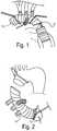
- FIG. 1illustrates one type of procedure for anastomosing an aortic arch graft.
- FIG. 2illustrates another type of procedure for anastomosing an aortic arch graft.
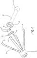
- FIG. 3is a perspective view of a stabilization tool according to one embodiment of the invention with retractable arms deployed to extended positions.
- FIG. 4is a perspective view of the stabilization tool of FIG. 3 with the retractable arms retracted to nested positions.
- FIG. 5is a perspective view of the stabilization tool of FIG. 3 mounted on a support arm.
- FIG. 6is a perspective view of the stabilization tool mounted on a support arm and disposed within a graft for holding the graft open during suturing.
- FIG. 7is a perspective view showing the stabilization tool in greater detail.
- FIG. 8is another perspective view of the stabilization tool.
- FIG. 9is a close-up view of one embodiment of the opening/closing mechanism with the arms in an extended position.
- FIG. 10is a perspective view of a central shaft with integral retractable arms according to one preferred embodiment.
- FIG. 11is a side view of a portion of the tool showing the arms in a nested position even though the closing ring is not shown.
- FIG. 12is a perspective view of the closing ring, control ring, and push-pull cable which can be combined with the portion of the tool shown in FIG. 11 .
- the inventionprovides an assistant tool particularly adapted to be used in vascular graft operation in order to secure visibility and working space for anastomosis.
- a stabilizer support arme.g., the HerculesTM Stabilizer Arm available from Terumo Cardiovascular Systems of Ann Arbor, Mich.
- a surgeoncan manipulate and secure an arch graft to a specific position for good visibility and suture without additional human assistance.
- FIGS. 1 and 2illustrate suturing of a branched graft 10 to replace an aortic arch.
- graft 10is being sutured to a descending aorta 11 via an extension graft 12 .
- graft 10is being sutured to an ascending aorta 13 .
- FIGS. 3 and 4are open and closed configurations of an “inside support umbrella-frame” stabilization tool 15 .
- a plurality of retractable arms 22are movable to a nested position ( FIG. 4 ), a maximum extended position ( FIG. 3 ), and a range of extended positions between them.
- a central shaftends with a ball 21 as a mounting element that is adapted to be captured on a support arm using a conventional “quick connect” mechanism.
- FIG. 5shows tool 15 mounted at the end of a support arm. For illustration, tool 15 is shown with the arm is an extended position although they would typically be retracted to the nested position prior to placement inside the vessel being sutured.
- FIG. 6shows the supported tool 15 holding open graft 10 .
- FIGS. 7-9show the open configuration of tool 15 in greater detail.
- a main, central shaft 20is bent or angled at an intermediate bend 25 .
- Shaft 20has mounting ball 21 at the proximal end and a set of retractable spring arms 22 at the distal end. There may be three or more arms 22 , preferably there are four. Arms 22 are arranged to naturally spring outward in a maximum extended position as shown. Proximal ends 32 of retractable arms 22 are spaced away from central shaft 20 when in the extended positions.
- a closing ring 23has an inside diameter configured to slide over arms 22 in order to retract arms 22 into a closed configuration with each arm 22 at a nested position flanking shaft 20 ( FIGS. 4 and 11 ). Closing ring 23 is connected to a manual control ring 24 by push-pull cables or wires 26 that extend through fixed eyelets 27 and a pair of aligned slots 29 in a hub 28 .
- Closing ring 23is slidable over retractable arms 22 from a deployed position adjacent the distal end of central shaft 20 to a retracted position spaced away from the distal end.
- Control ring 24slides along central shaft 20 under manual control of a surgeon.
- Push-pull cables 26connect control ring 24 and closing ring 23 so that motion of control ring 24 is replicated by closing ring 23 to reconfigure retractable arms 22 between the nested position and an extended position within the range of extended positions.
- cables 26should be sufficiently stiff to be able to push closing ring 23 from the retracted position to the deployed position.
- cables 26may preferably be comprised of metallic wire (such as stainless steel) or a molded thermoplastic (such as TPE or TPO).
- tool 15could be reconfigured from the closed to open position without relying on cables 26 by pulling directly on closing ring 23 since it may be acceptable to deploy arms 22 prior to placement within the vessel.
- FIG. 10shows the natural, undeflected position of retractable spring arms 22 in relation to central shaft 20 .
- An end plate 35joins shaft 20 to arms 22 .
- Plate 35 , shaft 20 , and arms 22can all be part of an integrally molded unit (i.e., all formed of the same plastic).
- Arms 22can alternatively be made of metal (such as a spring grade stainless steel), with arms 22 being insert molded into plate 35 .
- the various components of tool 15may be comprised of injection molded parts using a biocompatible thermoplastic, metallic parts (e.g., stainless steel), or a combination of plastic and metallic parts.
Landscapes
- Health & Medical Sciences (AREA)
- Life Sciences & Earth Sciences (AREA)
- Engineering & Computer Science (AREA)
- Biomedical Technology (AREA)
- General Health & Medical Sciences (AREA)
- Heart & Thoracic Surgery (AREA)
- Animal Behavior & Ethology (AREA)
- Public Health (AREA)
- Veterinary Medicine (AREA)
- Surgery (AREA)
- Cardiology (AREA)
- Vascular Medicine (AREA)
- Transplantation (AREA)
- Oral & Maxillofacial Surgery (AREA)
- Molecular Biology (AREA)
- Nuclear Medicine, Radiotherapy & Molecular Imaging (AREA)
- Medical Informatics (AREA)
- Pulmonology (AREA)
- Gastroenterology & Hepatology (AREA)
- Surgical Instruments (AREA)
Abstract
Description
Claims (12)
Priority Applications (1)
| Application Number | Priority Date | Filing Date | Title |
|---|---|---|---|
| US15/679,502US10531947B2 (en) | 2016-08-24 | 2017-08-17 | Great vessel graft suturing aid |
Applications Claiming Priority (2)
| Application Number | Priority Date | Filing Date | Title |
|---|---|---|---|
| US201662378981P | 2016-08-24 | 2016-08-24 | |
| US15/679,502US10531947B2 (en) | 2016-08-24 | 2017-08-17 | Great vessel graft suturing aid |
Publications (2)
| Publication Number | Publication Date |
|---|---|
| US20180055621A1 US20180055621A1 (en) | 2018-03-01 |
| US10531947B2true US10531947B2 (en) | 2020-01-14 |
Family
ID=61241027
Family Applications (1)
| Application Number | Title | Priority Date | Filing Date |
|---|---|---|---|
| US15/679,502Expired - Fee RelatedUS10531947B2 (en) | 2016-08-24 | 2017-08-17 | Great vessel graft suturing aid |
Country Status (2)
| Country | Link |
|---|---|
| US (1) | US10531947B2 (en) |
| WO (1) | WO2018039042A1 (en) |
Families Citing this family (1)
| Publication number | Priority date | Publication date | Assignee | Title |
|---|---|---|---|---|
| CN116269584B (en)* | 2023-05-17 | 2023-08-29 | 泓欣科创(北京)科技有限公司 | Auxiliary hanging ring device and vascular anastomat |
Citations (11)
| Publication number | Priority date | Publication date | Assignee | Title |
|---|---|---|---|---|
| US5503617A (en) | 1994-07-19 | 1996-04-02 | Jako; Geza J. | Retractor and method for direct access endoscopic surgery |
| US5885238A (en) | 1991-07-16 | 1999-03-23 | Heartport, Inc. | System for cardiac procedures |
| US20040030348A1 (en) | 1998-11-06 | 2004-02-12 | St. Jude Medical Atg, Inc. | Medical graft connector and methods of making and installing same |
| US20040050393A1 (en) | 2002-09-12 | 2004-03-18 | Steve Golden | Anastomosis apparatus and methods |
| US20050251175A1 (en)* | 2004-05-07 | 2005-11-10 | Ethicon Endo-Surgery, Inc. | Anchors for use in attachment of bladder tissues to pelvic floor tissues following a prostatectomy |
| US20060241748A1 (en) | 2005-03-25 | 2006-10-26 | Lee Leonard Y | Methods and apparatus for controlling the internal circumference of an anatomic orifice or lumen |
| US20060253137A1 (en)* | 2005-05-03 | 2006-11-09 | Ethicon Endo-Surgery, Inc. | Sheathless anastomotic ring applier device |
| US20070021759A1 (en)* | 2005-07-22 | 2007-01-25 | Ethicon Endo-Surgery, Inc. | Flexible endoscopic anastomotic ring applier device |
| US20070282355A1 (en) | 2006-06-01 | 2007-12-06 | Wilson-Cook Medical Inc. | Release mechanisms for a clip device |
| US7717844B2 (en) | 2006-07-06 | 2010-05-18 | Apaxis Medical, Inc. | Method and apparatus for stabilization and positioning during surgery |
| US20140276975A1 (en) | 2013-03-13 | 2014-09-18 | Medtronic Vascular, Inc. | Suturing Device and Method for Sealing an Opening in a Blood Vessel or Other Biological Structure |
- 2017
- 2017-08-17USUS15/679,502patent/US10531947B2/ennot_activeExpired - Fee Related
- 2017-08-17WOPCT/US2017/047399patent/WO2018039042A1/ennot_activeCeased
Patent Citations (11)
| Publication number | Priority date | Publication date | Assignee | Title |
|---|---|---|---|---|
| US5885238A (en) | 1991-07-16 | 1999-03-23 | Heartport, Inc. | System for cardiac procedures |
| US5503617A (en) | 1994-07-19 | 1996-04-02 | Jako; Geza J. | Retractor and method for direct access endoscopic surgery |
| US20040030348A1 (en) | 1998-11-06 | 2004-02-12 | St. Jude Medical Atg, Inc. | Medical graft connector and methods of making and installing same |
| US20040050393A1 (en) | 2002-09-12 | 2004-03-18 | Steve Golden | Anastomosis apparatus and methods |
| US20050251175A1 (en)* | 2004-05-07 | 2005-11-10 | Ethicon Endo-Surgery, Inc. | Anchors for use in attachment of bladder tissues to pelvic floor tissues following a prostatectomy |
| US20060241748A1 (en) | 2005-03-25 | 2006-10-26 | Lee Leonard Y | Methods and apparatus for controlling the internal circumference of an anatomic orifice or lumen |
| US20060253137A1 (en)* | 2005-05-03 | 2006-11-09 | Ethicon Endo-Surgery, Inc. | Sheathless anastomotic ring applier device |
| US20070021759A1 (en)* | 2005-07-22 | 2007-01-25 | Ethicon Endo-Surgery, Inc. | Flexible endoscopic anastomotic ring applier device |
| US20070282355A1 (en) | 2006-06-01 | 2007-12-06 | Wilson-Cook Medical Inc. | Release mechanisms for a clip device |
| US7717844B2 (en) | 2006-07-06 | 2010-05-18 | Apaxis Medical, Inc. | Method and apparatus for stabilization and positioning during surgery |
| US20140276975A1 (en) | 2013-03-13 | 2014-09-18 | Medtronic Vascular, Inc. | Suturing Device and Method for Sealing an Opening in a Blood Vessel or Other Biological Structure |
Also Published As
| Publication number | Publication date |
|---|---|
| WO2018039042A1 (en) | 2018-03-01 |
| US20180055621A1 (en) | 2018-03-01 |
Similar Documents
| Publication | Publication Date | Title |
|---|---|---|
| US11432925B2 (en) | Catheter assembly with prosthesis crimping and prosthesis retaining accessories | |
| US11850139B2 (en) | Embolic protection basket apparatus | |
| US11109968B2 (en) | Apparatus and methods for improved loading of a transcatheter heart valve | |
| EP2538883B1 (en) | Catheter assembly with valve crimping accessories | |
| US8262719B2 (en) | Braided flange branch graft for branch vessel | |
| US8133266B2 (en) | Expandable tip delivery system and method | |
| US20200323635A1 (en) | A device for inserting a guide wire in a blood vessel | |
| US7608100B2 (en) | Intraluminal graft assembly and vessel repair system | |
| CN104411357A (en) | Embolic protection system | |
| CN101861134A (en) | Treatment device for blood circulation pipeline | |
| JP2012523891A (en) | Antegrade deployment prosthesis | |
| WO2025051268A1 (en) | Covered stent, stent system and usage | |
| EP3618730B1 (en) | Apparatuses for use in surgical vascular anastomotic procedures | |
| US10531947B2 (en) | Great vessel graft suturing aid | |
| US20250275849A1 (en) | Thoracoaortic hybrid graft and surgical methods thereof | |
| JP2021527543A (en) | Embolic devices for promoting thrombus formation and methods of recovering the embolic devices from body lumens | |
| WO2014045403A1 (en) | Delivery system |
Legal Events
| Date | Code | Title | Description |
|---|---|---|---|
| AS | Assignment | Owner name:TERUMO CARDIOVASCULAR SYSTEMS CORPORATION, MICHIGA Free format text:ASSIGNMENT OF ASSIGNORS INTEREST;ASSIGNOR:TSUBOUCHI, TAKESHI;REEL/FRAME:043320/0393 Effective date:20170817 | |
| STPP | Information on status: patent application and granting procedure in general | Free format text:DOCKETED NEW CASE - READY FOR EXAMINATION | |
| STPP | Information on status: patent application and granting procedure in general | Free format text:NON FINAL ACTION MAILED | |
| STPP | Information on status: patent application and granting procedure in general | Free format text:RESPONSE TO NON-FINAL OFFICE ACTION ENTERED AND FORWARDED TO EXAMINER | |
| STPP | Information on status: patent application and granting procedure in general | Free format text:FINAL REJECTION MAILED | |
| STPP | Information on status: patent application and granting procedure in general | Free format text:NOTICE OF ALLOWANCE MAILED -- APPLICATION RECEIVED IN OFFICE OF PUBLICATIONS | |
| STPP | Information on status: patent application and granting procedure in general | Free format text:PUBLICATIONS -- ISSUE FEE PAYMENT VERIFIED | |
| STCF | Information on status: patent grant | Free format text:PATENTED CASE | |
| FEPP | Fee payment procedure | Free format text:MAINTENANCE FEE REMINDER MAILED (ORIGINAL EVENT CODE: REM.); ENTITY STATUS OF PATENT OWNER: LARGE ENTITY | |
| LAPS | Lapse for failure to pay maintenance fees | Free format text:PATENT EXPIRED FOR FAILURE TO PAY MAINTENANCE FEES (ORIGINAL EVENT CODE: EXP.); ENTITY STATUS OF PATENT OWNER: LARGE ENTITY | |
| STCH | Information on status: patent discontinuation | Free format text:PATENT EXPIRED DUE TO NONPAYMENT OF MAINTENANCE FEES UNDER 37 CFR 1.362 | |
| FP | Lapsed due to failure to pay maintenance fee | Effective date:20240114 |