US10531896B2 - Distraction tube with wire clamp - Google Patents
Distraction tube with wire clampDownload PDFInfo
- Publication number
- US10531896B2 US10531896B2US14/997,038US201614997038AUS10531896B2US 10531896 B2US10531896 B2US 10531896B2US 201614997038 AUS201614997038 AUS 201614997038AUS 10531896 B2US10531896 B2US 10531896B2
- Authority
- US
- United States
- Prior art keywords
- receiving portion
- rod receiving
- pin
- rod
- fixation
- Prior art date
- Legal status (The legal status is an assumption and is not a legal conclusion. Google has not performed a legal analysis and makes no representation as to the accuracy of the status listed.)
- Active, expires
Links
Images


Classifications
- A—HUMAN NECESSITIES
- A61—MEDICAL OR VETERINARY SCIENCE; HYGIENE
- A61B—DIAGNOSIS; SURGERY; IDENTIFICATION
- A61B17/00—Surgical instruments, devices or methods
- A61B17/56—Surgical instruments or methods for treatment of bones or joints; Devices specially adapted therefor
- A61B17/58—Surgical instruments or methods for treatment of bones or joints; Devices specially adapted therefor for osteosynthesis, e.g. bone plates, screws or setting implements
- A61B17/60—Surgical instruments or methods for treatment of bones or joints; Devices specially adapted therefor for osteosynthesis, e.g. bone plates, screws or setting implements for external osteosynthesis, e.g. distractors, contractors
- A61B17/66—Alignment, compression or distraction mechanisms
- A—HUMAN NECESSITIES
- A61—MEDICAL OR VETERINARY SCIENCE; HYGIENE
- A61B—DIAGNOSIS; SURGERY; IDENTIFICATION
- A61B17/00—Surgical instruments, devices or methods
- A61B17/56—Surgical instruments or methods for treatment of bones or joints; Devices specially adapted therefor
- A61B17/58—Surgical instruments or methods for treatment of bones or joints; Devices specially adapted therefor for osteosynthesis, e.g. bone plates, screws or setting implements
- A61B17/60—Surgical instruments or methods for treatment of bones or joints; Devices specially adapted therefor for osteosynthesis, e.g. bone plates, screws or setting implements for external osteosynthesis, e.g. distractors, contractors
- A61B17/64—Devices extending alongside the bones to be positioned
- A61B17/6416—Devices extending alongside the bones to be positioned with non-continuous, e.g. hinged, pin-clamp connecting element
- A—HUMAN NECESSITIES
- A61—MEDICAL OR VETERINARY SCIENCE; HYGIENE
- A61B—DIAGNOSIS; SURGERY; IDENTIFICATION
- A61B17/00—Surgical instruments, devices or methods
- A61B17/56—Surgical instruments or methods for treatment of bones or joints; Devices specially adapted therefor
- A61B17/58—Surgical instruments or methods for treatment of bones or joints; Devices specially adapted therefor for osteosynthesis, e.g. bone plates, screws or setting implements
- A61B17/60—Surgical instruments or methods for treatment of bones or joints; Devices specially adapted therefor for osteosynthesis, e.g. bone plates, screws or setting implements for external osteosynthesis, e.g. distractors, contractors
- A61B17/64—Devices extending alongside the bones to be positioned
- A61B17/6466—Devices extending alongside the bones to be positioned with pin-clamps movable along a solid connecting rod
- A—HUMAN NECESSITIES
- A61—MEDICAL OR VETERINARY SCIENCE; HYGIENE
- A61B—DIAGNOSIS; SURGERY; IDENTIFICATION
- A61B17/00—Surgical instruments, devices or methods
- A61B2017/00982—General structural features
- A61B2017/00991—Telescopic means
Definitions
- the present inventionrelates to external fixation systems and methods, and in particular relates to improved fixation pin positioning and orientation using dynamic housing members with clamping portions coupled to a telescoping body.
- Such systemsgenerally use rings, fixation plates, threaded rods or struts for manipulation, angulation, and translation of the deformities of bones.
- Some existing fixation systems on the markethave components that are static and do not allow for certain adjustment and/or pivoting. Lack of flexibility in a system may restrict attachment to certain bone areas at certain angles as well as restrict motion of the portion of the body that the external fixation system is being attached to in order to correct. Because of such lack of flexibility, such systems may make it more difficult for the physician to achieve an optimal clinical outcome.
- Mini-railsare external fixation systems known in the art that are used to control distraction and compression during lengthening or deformity correction procedures generally of small bones. The primary use of these systems are in the hand, foot and craniomaxillofacial (“CMF”) regions.
- CMFcraniomaxillofacial
- Existing mini-rail systemsare generally bulky, unnecessarily complex in procedure, and utilize pin configurations that generally flex during correction of bone fragments.
- prior art mini-railsgenerally consist of exposed threaded rods or “cages” which pin clamps translate on.
- the pin clampsmay allow for some polyaxial rotation of the pins that are coupled thereto; however, other degrees of freedom are generally restricted between the pin clamps and the fixation rod that the pin clamp is coupled to.
- many systemsare not configured such that other fixation devices could attach to it unless such other fixation devices are specifically designed to interface with the threaded rod or cage thereof, for example.
- the present inventionimproves upon existing mini-rails by allowing for greater flexibility in fixation pin clamping and placement.
- the systems and methods described hereinare indicated for use in osteotomies, arthrodeses, lengthening cases, fracture fixations, bone reconstruction procedures, revision procedures, non-unions, and delayed unions.
- the systems of the present inventionallow a physician to target the best bone possible for ideal pin placement and thread purchase by allowing insertion of fixation pins with different diameters, in multiple bone locations and at a wide variety of angles.
- the flexibility of the systems of the present inventionprovide physicians and surgeons the capacity to place pins in the positions they feel are most appropriate. Pairs of fixation pins can be oriented vertically, horizontally, or diagonally with respect to each other. Additionally, the incidence angle of each fixation pin as it is inserted into the bone can be adjusted independently.
- the systems described hereinalso provide cross platform compatibility by way of a standard 8 mm diameter compression/distraction tube that can easily be coupled to other external fixation devices if desired.
- the mini-rails of the present inventionhave a built-in thread such that the mini-rails may be used in other external fixation constructs, such as circular and conventional ex-fix systems, for example.
- the mini-rail systems described hereinutilizes a central telescoping tube that can be locked to at a variety of lengths. Housing members including clamping portions are then slid over the tube. The location of each housing member along the tube may be determined independently of each other.
- Each clamping portioncan hold two fixation pins of either the same or different diameters (ranging from 2-4 millimeters) through the use of two spring loaded jaws.
- These two fixation pinscan rotate fully and independently about the telescoping tube when the housing members and clamping portions are in an unlocked position.
- the spring loaded jawsallow the pin to rotate parallel to the telescoping tube. This bi-axial rotation allows the surgeon to position the pins vertically, horizontally, or diagonally with respect to each other. Tightening of one nut anchors both the pin to the clamping portion and the housing member to the central tube simultaneously.
- a first aspect of the present inventionis an external fixation device comprising an external fixation system comprising a first elongate rod, a first housing member and a first locking pin.
- the first housing memberhas a fixation pin clamping portion and a rod receiving portion, the fixation pin clamping portion having opposing jaws for receiving and clamping a fixation pin, the rod receiving portion including a longitudinal cavity housing at least a portion of the first elongate rod.
- the first locking pinis coupled to the fixation pin clamping portion and the rod receiving portion of the first housing member, wherein movement of the first locking pin in a first direction causes the opposing jaws of the fixation pin clamping portion and the rod receiving portion to compress toward one another such that the first housing member is in a locked state and cannot move with respect to the first elongate rod.
- the first locking pinis at least partially housed within a longitudinal bore defined by both of the fixation pin clamping portion and the rod receiving portion.
- the longitudinal borehas an axis perpendicular to an axis of the longitudinal cavity of the rod receiving portion.
- the a longitudinal axisis defined between the opposing jaws of the fixation pin clamping portion, the longitudinal axis being perpendicular to the longitudinal bore.
- fixation pin clamping portion and the rod receiving portionare rotatably coupled to one another about the axis of the longitudinal bore. Movement of the first locking pin in the first direction causes the fixation pin clamping portion and the rod receiving portion to compress toward one another such that the fixation pin clamping portion and the rod receiving portion cannot move with respect to one another.
- movement of the first locking pin in a second directionallows the opposing jaws of the fixation pin clamping portion and the rod receiving portion to move away from one another such that the first housing member is in an unlocked state and can move with respect to the first elongate rod.
- the first locking pinincludes an actuator portion and a shaft portion, the shaft portion being located within the longitudinal bore, the actuator portion being rotatable in the first direction.
- the rod receiving portionincludes first and second deflectable legs, the first and second deflectable legs moving toward one another when the first locking pin is moved in the first direction.
- a second elongate rodhas a longitudinal axis coaxial with a longitudinal axis of the first elongate rod when the first and second elongate rods are coupled, and wherein the first and second elongate rods translate with respect to one another along the longitudinal axes thereof.
- an external fixation devicecomprises a first elongate rod having a longitudinal axis, a first fixation pin portion having opposing jaws for receiving and clamping a fixation pin, a rod receiving portion rotatably coupled to the first fixation pin clamping portion, the rod receiving portion including a longitudinal cavity housing at least a portion of the first elongate rod, and a first locking pin coupled to the fixation pin clamping portion and the rod receiving portion of the first housing member, wherein movement of the first locking pin in a first direction causes the opposing jaws of the fixation pin clamping portion and the rod receiving portion to compress toward one another such that the first housing member is in a locked state and cannot move with respect to the first elongate rod.
- FIG. 1is a perspective view of one embodiment of an external fixation system of the present invention.
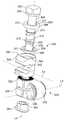
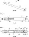
- FIG. 2Ais a perspective view of a distraction tube of the external fixation system of FIG. 1 .
- FIG. 2Bis a side view of the distraction tube of FIG. 2A .
- FIG. 2Cis a cross-section view of the distraction tube of FIG. 2A taken along line A-A.
- FIG. 2Dis an exploded perspective view of the distraction tube of FIG. 2A .
- FIG. 3Ais an exploded perspective view of an embodiment of a housing member of the present invention.
- FIG. 3Bis a front assembled view the housing member of FIG. 3A .
- FIG. 3Cis a cross-section view of the housing member of FIG. 3B taken along line B-B.
- FIG. 4Ais a perspective view of another embodiment of a housing member of the external fixation system of FIG. 1 .
- FIG. 4Bis a side view of the housing member of FIG. 4A .
- FIG. 4Cis a front view of the housing member of FIG. 4A .
- FIG. 5Ais a perspective view of another embodiment of a housing member of the external fixation system of FIG. 1 .
- FIG. 5Bis a side view of the housing member of FIG. 5A .
- FIG. 5Cis a front view of the housing member of FIG. 5A .
- FIG. 6is a perspective view of another embodiment of an external fixation system of the present invention.
- FIG. 1there is shown an embodiment of an external fixation system 100 having a distraction tube or telescoping rod 200 , a first housing member 400 , a second housing member 500 , and a plurality of fixation pins 600 coupled to respective clamping portions of the first and second housing members 400 , 500 .
- FIGS. 2A-2Bare assembled views of distraction tube 200 having an actuation member 240 , a first elongate tube member 260 , a second elongate tube member 280 , a spring clip 294 , a detent 296 and a ball 298 .
- actuation member 240includes an actuation portion 242 , a base portion 244 , an engagement portion 246 and a shaft portion 248 .
- Actuation portion 242projects outwardly in a distal direction from a distal end surface 250 of base portion 244 .
- Engagement portion 246projects outwardly in a proximal direction from a proximal end surface 252 of base portion 244 .
- Engagement portionhouses at least a portion of detent 296 and ball 298 .
- Shaft portion 248projects outwardly in a proximal direction from engagement portion 246 .
- Actuation portion 242is preferably configured to be engaged and manipulated by hand or with a tool.
- actuation portion 242has four angled flat surfaces 254 in a square configuration with four rounded edges 256 between adjacent surfaces 254 .
- Engagement portion 246preferably includes a circumferential recess 257 .
- Shaft portion 248includes threads 259 along substantially the entire length thereof.
- First elongate tube member 260includes a distal end surface 262 and a proximal end surface 264 .
- First elongate tube memberhas a bore 268 extending through the proximal and distal end surfaces 262 , 264 thereof and a protrusion 270 projecting outwardly from an inner surface 272 thereof.
- a plurality of apertures 274are located through a circumference of tube member 260 .
- Second elongate tube member 280includes a distal end surface 282 , a proximal end portion 284 , a tube portion 286 and a shaft portion 288 .
- Tube portion 286includes an inner threaded surface 290 and an outer surface 292 having a longitudinal recess 294 .
- Proximal end portion 284is shaped in order to couple second elongate tube member to other external fixation constructs, if desired.
- distal end surface 262 of first elongate tube member 260preferably mates with proximal end surface 252 of base portion 244 of actuation member 240 with shaft portion 248 of actuation member 240 being housed within bore 268 of first elongate member.
- Spring clip 294is at least partially received within circumferential recess 257 of actuation member 240 and a corresponding recess 271 within an inner surface 272 of first elongate tube member 260 .
- Rotation of actuation member 240may be calculated by the interaction of detent 296 , ball 298 , and the plurality of apertures 274 in first elongate tube member 260 .
- Each 90 degree rotation of actuation member 240either clockwise or counterclockwise amounts to a 1 mm change in length, for example, of distraction tube 200 .
- engagement portion 246 of actuation member 240engages inner surface 272 of first elongate tube member 260 .
- protrusion 270 of first elongate tube member 260is coupled to longitudinal recess 294 of tube portion 286 at distal end surface 282 of tube portion 286 and slid along longitudinal recess 294 until threaded portion 259 of shaft portion 248 of actuation member 240 comes in contact with inner threaded surface 290 of tube portion 286 of second elongate tube member 280 .
- Actuation portion 242is then rotated in a clockwise direction in order to thread shaft portion 248 onto threaded surface 290 .
- protrusion 270continues to ride along longitudinal recess 294 of tube portion 286 in a first direction until proximal end surface 264 lies adjacent a distal end surface 296 of shaft portion 288 .
- protrusion 270rides along longitudinal recess 294 , first elongate tube member 260 does not rotate with respect to second elongate tube member 280 . Instead, first elongate tube member 260 only translates with respect to second elongate tube 280 along longitudinal axis L 1 .
- protrusion 270will continue to ride along longitudinal recess 294 of tube portion 286 , but in a second direction along longitudinal axis L 1 such that proximal end surface 264 will be separated from distal end surface 296 of shaft portion 288 a larger linear distance from one another.
- rotation of actuation member 240 in either a clockwise or counterclockwise directionwill cause proximal end surface 264 and distal end surface 296 to move closer and further away from one another in a linear direction along longitudinal axis L 1 of external fixation system 100 .
- tube portion 286 of second elongate tube member 280has an outer surface 292 that is square shaped and has no longitudinal recess 292 in the outer surface thereof.
- first elongate tube member 260has a bore 268 having an inner surface 272 that is square shaped and no protrusion 270 projecting outwardly from the inner surface thereof.
- first elongate tube member 260square shaped inner surface 272 of first elongate tube member 260 is coupled to square shaped outer surface 292 of tube portion 286 of the second elongate tube member 280 at distal end surface 282 of tube portion 286 and is slid along the outer surface 292 until threaded portion 259 of shaft portion 248 of actuation member 240 comes in contact with inner threaded surface 290 of tube portion 286 of second elongate tube member 280 .
- Actuation portion 242is then rotated in a clockwise direction in order to threaded shaft portion 248 onto threaded surface 290 .
- FIGS. 3A-3Cshow a first embodiment of a housing member 300 of an external fixation system.
- Housing member 300includes a housing portion 320 , a clamping portion 340 , an actuation portion 360 , and a stopper portion 380 .
- Housing portion 320includes top and bottom portions 322 , 326 coupled by way of a curved connector portion 332 .
- Top and bottom portion 322 , 326may be referred to as deflectable legs for their ability to move toward and away from one another through their connection with curved connection portion 332 .
- Top portion 322includes a circumferentially grooved superior surface 323 , a substantially planar inferior surface 324 and an aperture 325 extending through surfaces 323 , 324 .
- Bottom portion 326includes substantially planar superior and inferior surfaces 327 , 328 and a stepped aperture 329 extending through surfaces 327 , 328 .
- Stepped aperture 329has a first aperture portion 330 and a second aperture portion 331 .
- a longitudinal axis L 2extends through surfaces 323 , 324 , 327 , 328 of top and bottom portions 322 , 326 .
- Curved connector portion 332has an inner curved surface 334 and an outer curved surface 336 .
- the coupling of curved connection portion 332 to top and bottom bore portions 322 , 326defines an aperture 338 having a longitudinal axis L 3 .
- Clamping portion 340includes first and second jaw portions 342 , 348 .
- First jaw portion 342has a superior surface 343 , an irregularly shaped inferior surface 344 and an aperture 354 extending through surfaces 343 , 344 .
- a chamfer surface 345 and a curved recess surface 346both extend from superior surface 343 toward inferior surface 344 .
- Inferior surface 344includes a substantially planar fixation pin contact surface 347 .
- Second jaw portion 348has an irregularly shaped superior surface 349 , a circumferentially grooved inferior surface 350 and an aperture 355 extending through surfaces 349 , 350 .
- a chamfer surface 351extends from inferior surface 350 toward superior surface 349 .
- Superior surfaceincludes angled first and second fixation pin contact surfaces 352 , 353 .
- Actuation portion 360includes a head portion 362 , a shaft portion 364 , a first washer 368 , a spring 372 , and a second washer 376 .
- Head portion 362 and shaft portion 364may collectively be referred to as a locking pin.
- Head portion 362is configured to be rotated manually or with a tool or driver.
- Head portion 362terminates at a planar surface 363 .
- First washer 368has superior and inferior surfaces 369 , 370 and an aperture 371 extending through superior and inferior surfaces 369 , 370 .
- Spring 372has a superior end 373 and an inferior end 374 .
- Second washer 376has a spherical head portion 377 , a shaft portion 378 and an aperture 379 extending through the spherical head portion 377 and shaft portion 378 .
- Housing member 300is first assembled by lining up actuation portion 360 , clamping portion 340 , housing portion 320 and stopper portion 380 along longitudinal axis L 2 . In doing so, apertures 354 , 355 of first and second jaw portions 342 , 348 of clamping portion 340 and apertures 325 , 329 of top and bottom portions 322 , 326 of housing portion 320 are aligned along longitudinal axis L 2 . First washer 368 , then spring 372 , then second washer 376 are assembled onto shaft portion 364 of actuation portion 360 such that shaft portion 364 extends through apertures in first washer 368 , spring 372 and second washer 376 .
- Shaft portion 364is then inserted through the aligned apertures 354 , 355 of first and second jaw portions 342 , 348 of clamping portion 340 and apertures 325 , 329 of top and bottom portions 322 , 326 of housing portion 320 until a distal end 365 of shaft portion 364 is at least partially located within stepped aperture 329 of bottom portion 326 of housing member 320 .
- Stopper portion 380is then at least partially inserted into aperture 329 and coupled to distal end 365 of shaft portion 364 .
- This couplingmay be a compression fit, but is preferably a threaded connection. Threads located on an inner surface 382 of stopper portion 380 engage threads on an outer surface 366 of shaft portion 364 .
- housing member 300can now be assembled to an elongated rod or distraction tube 200 , for example, of an external fixation system 100 of the present invention.
- This assemblyoccurs by inserting an end of an elongate rod or distraction tube 200 , for example, through aperture 338 of housing member 300 such that longitudinal axis L 1 of distraction tube 200 is substantially coaxial with longitudinal axis L 3 of aperture 338 .
- housing member 300should be in an unlocked state such that the inferior surface 324 of top portion 322 and superior surface 328 of bottom portion 326 are not in contact with one another and are separated from one another by a substantially planar distance.
- aperture 338has a neutral or relaxed diameter.
- actuation portioncan be actuated in order to bring the inferior surface 324 of top portion 322 and superior surface 328 of bottom portion 326 into contact with one another while compressing the diameter of aperture 338 such that the position and orientation of housing member 300 with respect to distraction tube 200 is set.
- a linear distance between the head portion 362 of actuation portion 360 and stopper portion 380is less than a linear distance between the head portion 362 of actuation portion 360 and stopper portion in the unlocked state.
- housing member 300may rotate about longitudinal axis L 1 .
- first and second jaw portions 342 , 348 of clamping portion 340may rotate with respect to top portion 322 of housing portion 320 about longitudinal axis L 2 which is preferably perpendicular and offset to longitudinal axis L 1 .
- Jaw portions 342 , 348generally correspondingly rotate about longitudinal axis L 2 because of irregularly shaped inferior surface 344 of jaw portion 342 having a corresponding shape to superior surface 349 of jaw portion 348 .
- jaw portions 342 , 348may be distracted away from or compressed toward longitudinal axis L 4 such that the space between surfaces 347 of jaw portion 342 and surfaces 352 , 353 of jaw portion 348 may be made greater or less depending on the location of the jaw portions 342 , 348 .
- fixation pin 600In clamping a fixation pin 600 such as that shown in FIG. 1 and FIG. 3B , for example, fixation pin 600 is inserted into the space between surfaces 347 of jaw portion 342 and surfaces 352 , 353 of jaw portion 348 at a particular position about the length of fixation pin 600 .
- head portion 362 of actuation portion 360begins to rotate in a clockwise manner about longitudinal axis L 2 , the components of housing member 300 begin to compress toward one another.
- a usershould set the position and orientation of housing member 300 with respect to distraction tube 200 .
- the jaw portions 342 , 348should be rotationally aligned with respect to housing portion 320 in a desired position by engaging the grooves of the circumferentially grooved superior surface 323 with the grooves of the circumferentially grooved inferior surface 350 .
- head portion 362 of actuation portion 360continues to rotate in a clockwise manner, the stopper portion 380 is brought into full engagement within stepped aperture 329 such that a contact portion 384 of stopper portion 380 comes into contact with a ledge portion 337 located at a base of aperture 331 of bottom portion 326 of housing portion 320 .
- FIGS. 4A-4Cshow an embodiment of a housing member 400 of external fixation system 100 shown in FIG. 1 .
- housing member 400includes an additional clamping portion, actuation portion and stopper portion.
- housing member 400includes a housing portion 420 , a first clamping portion 440 , a second clamping portion 440 ′, a first actuation portion 460 , a second actuation portion 460 ′, a first stopper portion 480 and a second stopper portion 480 ′.
- This embodimentprovides a physician, surgeon or any other operating room personnel with additional fixation pin coupling such that a first fixation pin can be coupled to first clamping portion 440 while a second fixation pin can be coupled to second clamping portion 440 ′. Because first and second clamping portions 440 , 440 ′ are able to be oriented and locked independently of one another, different size fixation pins and different locations and orientations of the fixation pins can be produced using housing member 400 . As shown in FIG. 1 , for example, housing member 400 allows pin 600 to have a first pin trajectory located in a first clamping portion and another pin to have a second pin trajectory located in a second clamping portion.
- housing portion 420 , first clamping portion 440 , first actuation portion 460 , and first stopper portion 480define a longitudinal axis L 2 ′ while housing portion 420 , second clamping portion 440 ′, second actuation portion 460 ′ and second stopper portion 480 ′ define a longitudinal axis L 2 ′′.
- Longitudinal axes L 2 ′ and L 2 ′′are generally parallel and offset to one another.
- FIGS. 5A-5Cshow another embodiment of a housing member 500 of external fixation system 100 shown in FIG. 1 .
- housing member 500includes first and second groups of clamping portions, actuation portions and stopper portions located in opposite directions of one another. It should be understood that the components of housing member 500 and their interaction with each other is the same as was described with respect to housing member 300 , with like reference numerals referring to like features in the present embodiment.
- housing member 500includes a housing portion 520 , a first clamping portion 540 , a second clamping portion 540 ′, a first actuation portion 560 , a second actuation portion 560 ′, a first stopper portion 580 and a second stopper portion 580 ′.
- This embodimentprovides a physician, surgeon or any other operating room personnel with variability in set fixation pins about longitudinal axis L 1 of external fixation system 100 .
- first and second clamping portions 540 , 540 ′are able to be oriented and locked independently of one another, different size fixation pins and different locations and orientations of the fixation pins can be produced suing housing member 500 .
- Housing portion 520 , first clamping portion 540 , first actuation portion 560 , and first stopper portion 580define a longitudinal axis L 2 ′′′ while housing portion 520 , second clamping portion 540 ′, second actuation portion 560 ′ and second stopper portion 580 ′ define a longitudinal axis L 2 ′′′′ such that longitudinal axes L 2 ′′′ and L 2 ′′′ are generally parallel and offset to one another.
- External fixation system 100 ′includes a first distraction tube 200 ′, a second distraction tube 200 ′′, first and second housing members 400 and a housing member 500 . Additional flexibility with respect to orienting fixation pins is provided with external fixation system 100 ′ by way of joint 150 .
- Distraction tube 200 ′terminates at a first joint end 160 while distraction tube 200 ′′ terminates at a second joint end 180 .
- First joint endinteracts with second joint end 180 such that distraction tube 200 ′ can pivot with respect to distraction tube 200 ′′ in several directions.
- Such a constructmay be advantageous for use with articulating bones and/or joints.
Landscapes
- Health & Medical Sciences (AREA)
- Orthopedic Medicine & Surgery (AREA)
- Life Sciences & Earth Sciences (AREA)
- Surgery (AREA)
- Biomedical Technology (AREA)
- Engineering & Computer Science (AREA)
- Nuclear Medicine, Radiotherapy & Molecular Imaging (AREA)
- Heart & Thoracic Surgery (AREA)
- Medical Informatics (AREA)
- Molecular Biology (AREA)
- Animal Behavior & Ethology (AREA)
- General Health & Medical Sciences (AREA)
- Public Health (AREA)
- Veterinary Medicine (AREA)
- Surgical Instruments (AREA)
Abstract
Description
Claims (19)
Priority Applications (1)
| Application Number | Priority Date | Filing Date | Title |
|---|---|---|---|
| US14/997,038US10531896B2 (en) | 2015-08-10 | 2016-01-15 | Distraction tube with wire clamp |
Applications Claiming Priority (2)
| Application Number | Priority Date | Filing Date | Title |
|---|---|---|---|
| US201562203174P | 2015-08-10 | 2015-08-10 | |
| US14/997,038US10531896B2 (en) | 2015-08-10 | 2016-01-15 | Distraction tube with wire clamp |
Publications (2)
| Publication Number | Publication Date |
|---|---|
| US20170042579A1 US20170042579A1 (en) | 2017-02-16 |
| US10531896B2true US10531896B2 (en) | 2020-01-14 |
Family
ID=57994555
Family Applications (1)
| Application Number | Title | Priority Date | Filing Date |
|---|---|---|---|
| US14/997,038Active2036-06-04US10531896B2 (en) | 2015-08-10 | 2016-01-15 | Distraction tube with wire clamp |
Country Status (1)
| Country | Link |
|---|---|
| US (1) | US10531896B2 (en) |
Cited By (1)
| Publication number | Priority date | Publication date | Assignee | Title |
|---|---|---|---|---|
| US20220226022A1 (en)* | 2019-05-27 | 2022-07-21 | Orthofix S.R.L. | Quick attachment clamp for external fixation systems |
Families Citing this family (4)
| Publication number | Priority date | Publication date | Assignee | Title |
|---|---|---|---|---|
| US9370380B2 (en) | 2013-03-15 | 2016-06-21 | Dne, Llc | External bone fixation system |
| US11291476B2 (en) | 2016-06-10 | 2022-04-05 | Dne, Llc | External bone fixation system |
| CN107582181B (en)* | 2017-10-12 | 2019-05-03 | 郑州大学第一附属医院 | A nerve intervention head and neck fixation device |
| TR202015042A2 (en)* | 2020-09-22 | 2022-03-21 | Atatuerk Ueniversitesi Rektoerluegue Bilimsel Arastirma Projeleri Bap Koordinasyon Birimi | A FIXATOR APPARATUS FOR THE TREATMENT OF OPEN CALCANEUS FRACTURES |
Citations (114)
| Publication number | Priority date | Publication date | Assignee | Title |
|---|---|---|---|---|
| US1201864A (en) | 1915-07-06 | 1916-10-17 | George William Overmeyer | Surgical appliance. |
| US2251209A (en) | 1940-02-17 | 1941-07-29 | Stader Otto | Bone splint |
| US2406987A (en)* | 1943-01-04 | 1946-09-03 | Anderson Roger | Fracture splint |
| US2497626A (en) | 1945-11-09 | 1950-02-14 | Persall Roy | Surgical splint |
| GB2033758A (en) | 1978-10-28 | 1980-05-29 | Aesculap Werke Ag | Fracture fixing appliance |
| US4456004A (en) | 1981-07-21 | 1984-06-26 | Kenny Charles H | Fracture holding |
| US4483334A (en)* | 1983-04-11 | 1984-11-20 | Murray William M | External fixation device |
| US4502473A (en) | 1981-08-06 | 1985-03-05 | National Research Development Corp. | Apparatus for external fixation of bone fractures |
| US4548199A (en) | 1981-11-13 | 1985-10-22 | Agee John M | Fracture splint |
| US4600000A (en) | 1982-09-16 | 1986-07-15 | Edwards Charles C | External fixation system |
| US4611586A (en) | 1983-10-06 | 1986-09-16 | John M. Agee | Articulated Colles' fracture splint |
| US4628919A (en) | 1983-09-09 | 1986-12-16 | Clyburn Terry | Dynamic external fixator and method of use |
| SU1281260A1 (en) | 1985-01-24 | 1987-01-07 | Харьковский Научно-Исследовательский Институт Ортопедии И Травматологии Им.Проф.М.И.Ситенко | Apparatus for osteosynthesis |
| EP0240034A1 (en) | 1986-04-04 | 1987-10-07 | Ulrich Dr.-Ing. Witzel | External fixation for osteosynthesis |
| US4714076A (en) | 1984-01-19 | 1987-12-22 | Synthes | Device for the setting of bone segments |
| US4730608A (en) | 1986-03-05 | 1988-03-15 | Schlein Allen P | External bone-anchoring fixator |
| EP0314021A2 (en) | 1987-10-26 | 1989-05-03 | Howmedica GmbH | Fixing device for parts of bones |
| US4890631A (en)* | 1985-02-22 | 1990-01-02 | Societe De Realisations Electro-Mecaniques Sorem | External fixation device intended for orthopedic use |
| US4895141A (en) | 1984-04-26 | 1990-01-23 | Harrington Arthritis Research Center | Unilateral external fixation device |
| US4968316A (en) | 1988-12-12 | 1990-11-06 | Hergenroeder Patrick T | Arthroscopic ankle joint distraction method |
| US4988349A (en) | 1987-01-21 | 1991-01-29 | Orthofix S.R.L. | Device for osteosynthesis |
| US4998935A (en) | 1989-08-16 | 1991-03-12 | Dietmar Pennig | Foot supporting extension for external fixation units |
| EP0469966A1 (en) | 1990-07-31 | 1992-02-05 | Faro Medical Technologies (Us) Inc. | Computer-aided surgery apparatus |
| US5122140A (en) | 1989-08-23 | 1992-06-16 | Jaquet Orthopedie, S.A. | Dynamic external fixation device |
| US5207676A (en) | 1989-02-27 | 1993-05-04 | Jaquet Orthopedie S.A. | External fixator with controllable damping |
| US5281221A (en) | 1990-12-05 | 1994-01-25 | Tadych Kevin L | Antimicrobial device for use in external fixators |
| US5393161A (en) | 1990-12-10 | 1995-02-28 | Jaquet Orthopedie S.A. | External fixator |
| US5429637A (en) | 1991-11-08 | 1995-07-04 | Hardy; Jean M. | External modular fixator for immobilization of a fracture |
| US5437666A (en) | 1992-08-24 | 1995-08-01 | Synthes (U.S.A.) | External fixation device for osteosynthesis |
| US5545162A (en) | 1995-02-15 | 1996-08-13 | Huebner; Randall J. | External fixator for repairing fractures of distal radius and wrist |
| US5601551A (en) | 1995-03-01 | 1997-02-11 | Smith & Nephew Richards, Inc. | Geared external fixator |
| US5620442A (en) | 1995-05-12 | 1997-04-15 | Bailey; Kirk J. | Method and apparatus for external fixation of small bones |
| US5624440A (en) | 1996-01-11 | 1997-04-29 | Huebner; Randall J. | Compact small bone fixator |
| US5628819A (en) | 1995-09-28 | 1997-05-13 | Calgon Carbon Corporation | Method and apparatus for continuous adsorption of adsorbable contaminates and adsorber regeneration |
| US5658283A (en) | 1995-02-15 | 1997-08-19 | Huebner; Randall J. | External fixator for repairing fractures |
| US5662649A (en) | 1995-02-15 | 1997-09-02 | Huebner; Randall J. | External fixator for repairing fractures of distal radius and wrist |
| US5674221A (en) | 1995-10-23 | 1997-10-07 | Orthopaedic Innovations, Inc. | External fixator with improved clamp and methods for use |
| US5683389A (en) | 1994-12-05 | 1997-11-04 | Smith & Nephew, Inc. | External fixator for distal radius fractures |
| US5690633A (en) | 1994-09-23 | 1997-11-25 | Smith & Nephew Richards, Inc. | Orthopedic fracture fixation device |
| US5695496A (en) | 1995-01-17 | 1997-12-09 | Smith & Nephew Inc. | Method of measuring bone strain to detect fracture consolidation |
| US5709681A (en) | 1995-09-19 | 1998-01-20 | Pennig; Dietmar | Device for osteosynthesis |
| US5752954A (en)* | 1994-09-06 | 1998-05-19 | Howmedica International | External fixation device |
| US5897555A (en) | 1997-05-15 | 1999-04-27 | Wright Medical Technology, Inc. | External fixation system and method |
| US5976133A (en) | 1997-04-23 | 1999-11-02 | Trustees Of Tufts College | External fixator clamp and system |
| US6010501A (en) | 1997-12-15 | 2000-01-04 | Electro-Biology, Inc. | Method and apparatus for external fixation of small bones |
| US6022348A (en)* | 1997-11-30 | 2000-02-08 | Spitzer; Daniel | Clamping connection for medical equipment and apparatus |
| EP1016381A1 (en)* | 1998-11-23 | 2000-07-05 | Hraklis Kourtis | External fixation system with telescopic pin or arm holding unit |
| US6152925A (en) | 1998-03-04 | 2000-11-28 | University Of Iowa Research Foundation | Method and apparatus for external fixation of an elbow |
| US6162224A (en) | 1995-02-15 | 2000-12-19 | Acumed, Inc. | External fixator for repairing fractures of distal radius and wrist |
| US6162223A (en) | 1999-04-09 | 2000-12-19 | Smith & Nephew, Inc. | Dynamic wrist fixation apparatus for early joint motion in distal radius fractures |
| US6171309B1 (en) | 1995-02-15 | 2001-01-09 | Acumed, Inc. | External fixator for repairing fractures of distal radius and wrist |
| US6176860B1 (en) | 1995-07-24 | 2001-01-23 | Hadasit Medical Research Services & Development Company, Ltd. | Orthopaedic fixator |
| US6277119B1 (en)* | 1999-10-21 | 2001-08-21 | Electro-Biology, Inc. | External fixation system |
| US20010034520A1 (en) | 2000-02-18 | 2001-10-25 | Albert Enayati | Bioabsorbable pin for external bone fixation |
| US20020004659A1 (en) | 2000-04-28 | 2002-01-10 | Fixano | External fixator for immobilizing bone fragments, particularly in the area of the wrist |
| US6342054B1 (en) | 1998-12-29 | 2002-01-29 | Stryker Trauma Sa | Positioning and locking device |
| US6409729B1 (en)* | 1998-05-19 | 2002-06-25 | Synthes (Usa) | Clamp assembly for an external fixation system |
| EP1254640A2 (en) | 2001-05-02 | 2002-11-06 | Biomet Merck Limited | Swivel coupling |
| US20020165543A1 (en)* | 2000-02-02 | 2002-11-07 | Winquist Robert A. | Adjustable bone stabilizing frame system |
| FR2831792A1 (en) | 2001-11-05 | 2003-05-09 | Jean Jacques Martin | External bone fragment fixator has pins held in split rings with outer spherical surfaces for adjustment and locking in holder |
| US6575972B1 (en) | 2000-04-28 | 2003-06-10 | Vanderbilt University | Wrap spring clamp |
| US20030149430A1 (en) | 2002-02-04 | 2003-08-07 | Joseph Ferrante | Devices, systems, and methods for placing and positioning fixation elements in external fixation systems |
| US20030149429A1 (en) | 2002-02-04 | 2003-08-07 | Joseph Ferrante | External fixation system |
| US20030187432A1 (en)* | 2002-03-28 | 2003-10-02 | Johnson Tab C. | External fixation system |
| US20030191468A1 (en)* | 2000-12-14 | 2003-10-09 | Synthes U.S.A. | Multipin clamp and rod attachment |
| US6652523B1 (en) | 1998-12-29 | 2003-11-25 | Delegation General Pour L'armement | Monolateral orthopedic device with external fixing for immobilizing a fractured bone |
| US20040097944A1 (en) | 2002-07-30 | 2004-05-20 | Koman L. Andrew | Fixation device and method for treating contractures and other orthopedic indications |
| US20040133199A1 (en) | 2001-03-05 | 2004-07-08 | Michele Coati | External fixation device for reducing bone fractures |
| US20040138659A1 (en) | 2003-01-10 | 2004-07-15 | Ed Austin | External fixation apparatus and method |
| US20050113829A1 (en) | 2002-07-15 | 2005-05-26 | Ebi, L.P. | Method and apparatus for the external fixation and correction of bone |
| US20050245939A1 (en)* | 2002-06-14 | 2005-11-03 | Joseph Ferrante | Device and methods for placing external fixation elements |
| US20060039750A1 (en)* | 2004-08-20 | 2006-02-23 | Stryker Trauma S.A. | Clamping and articulation element |
| US20060052781A1 (en)* | 2004-08-20 | 2006-03-09 | Stryker Trauma S.A. | Clamp for multiple rod-shaped elements |
| US20060229605A1 (en) | 2005-03-18 | 2006-10-12 | Olsen Ron A | Adjustable splint for osteosynthesis with incrementing assembly for adjustment in predetermined increments |
| US20060235383A1 (en) | 2005-03-07 | 2006-10-19 | Shane Hollawell | External fixator |
| US20060247629A1 (en)* | 2005-04-27 | 2006-11-02 | Maughan Thomas J | Bone fixation apparatus |
| US20070038217A1 (en) | 2005-08-09 | 2007-02-15 | Brown Daniel G | Orthopaedic fixation clamp and method |
| US20070100338A1 (en) | 2005-10-27 | 2007-05-03 | Deffenbaugh Daren L | Orthopaedic instrument joint, instrument and associated method |
| US20070123856A1 (en) | 2005-10-27 | 2007-05-31 | Deffenbaugh Daren L | Trauma joint, external fixator and associated method |
| US20070123857A1 (en) | 2005-10-27 | 2007-05-31 | Deffenbaugh Daren L | Orthopaedic joint, device and associated method |
| US7252669B1 (en) | 2003-09-23 | 2007-08-07 | Mcintyre John | Fixator pin cap |
| US20070198012A1 (en)* | 2006-02-21 | 2007-08-23 | Stryker Trauma Sa | Clamping and articulation element |
| US20070233061A1 (en) | 2006-03-31 | 2007-10-04 | Stryker Trauma S.A. | External fixator element |
| US7407504B2 (en) | 2003-01-15 | 2008-08-05 | Christian Dongar | Device for immobilishing an osteosynthesis pin in a bone part |
| US20080221571A1 (en) | 2007-03-07 | 2008-09-11 | Aaron Daluiski | External Fixation |
| US20080247818A1 (en) | 2004-03-10 | 2008-10-09 | Marc Oesch | Device For Mutual Positioning of Longitudinal Building Components |
| US20090088751A1 (en) | 2007-09-27 | 2009-04-02 | Qfx Technologies, Incorporated | Method and Clamping Apparatus for External Fixation and Stabilization |
| US20090198234A1 (en)* | 2008-02-01 | 2009-08-06 | Stryker Trauma Sa | Telescopic strut for an external fixator |
| US20090287212A1 (en) | 2006-05-26 | 2009-11-19 | National University Corporation Nagoya University | External fixator |
| US20090299368A1 (en) | 2005-04-01 | 2009-12-03 | Tantum Ag | Fixation Device for Stably Interlinking At Least Two Bone Fragments of a Broken Bone and Corresponding Fixation Element and Kit |
| US20100076436A1 (en) | 2007-08-16 | 2010-03-25 | Nutek Orthopaedics, Inc. | Apparatus for external fixation of a fractured distal radius with angularly adjustable pin clamping means |
| US7806623B2 (en) | 2005-02-09 | 2010-10-05 | Stryker Trauma S.A. | External fixation clamp |
| US20100298827A1 (en)* | 2009-05-15 | 2010-11-25 | Stryker Trauma Sa | Fixation clamp |
| USD633208S1 (en) | 2009-09-11 | 2011-02-22 | Stryker Trauma Ag | External fixation clamp |
| US20110082458A1 (en) | 2009-10-05 | 2011-04-07 | Stryker Trauma Sa | Dynamic External Fixator And Methods For Use |
| US20110172664A1 (en) | 2008-09-16 | 2011-07-14 | Orthofix S.R.L. | Orthopaedic device for correcting deformities of long bones |
| US20110230882A1 (en) | 2010-03-19 | 2011-09-22 | Rafael Ben | Bone Distraction System |
| US8057473B2 (en) | 2007-10-31 | 2011-11-15 | Wright Medical Technology, Inc. | Orthopedic device |
| US20120004659A1 (en)* | 2010-07-01 | 2012-01-05 | Extraortho, Inc. | Multi-Locking External Fixation Clamp |
| US20120089142A1 (en)* | 2010-10-12 | 2012-04-12 | Extraortho, Inc. | Single Lock External Fixation Clamp Arrangement and Method |
| US20120095462A1 (en) | 2010-10-12 | 2012-04-19 | Extraortho, Inc. | External Fixation Surgical Clamp with Swivel |
| US20120150180A1 (en) | 2010-12-09 | 2012-06-14 | Stryker Trauma Sa | Adjustment tool for external fixator |
| US20120150184A1 (en) | 2010-12-09 | 2012-06-14 | Extraortho, Inc. | Cam Driven Jaw for External Fixation Clamps |
| US20120150185A1 (en) | 2010-12-09 | 2012-06-14 | Extraortho, Inc. | Revolving Lock for External Fixation Clamps |
| US20120150186A1 (en) | 2007-08-16 | 2012-06-14 | Nutek Orthopaedics, Inc. | External fixation apparatus with angularly adjustable drill guiding and pin clamping means |
| US8206388B2 (en) | 2004-11-30 | 2012-06-26 | Stryker Trauma S.A. | Insert for a clamping element, clamping element comprising said insert and universal joint produced therefrom |
| US20120203225A1 (en) | 2009-11-05 | 2012-08-09 | Citieffe S.R.L. | Multi-purpose external fixator |
| US20120209266A1 (en) | 2011-02-11 | 2012-08-16 | Orthofix S.R.L. | External orthopaedic fixator for the elbow joint |
| US20120289959A1 (en) | 2010-11-04 | 2012-11-15 | Extraortho, Inc. | Clamping Assembly with Links |
| US20120296335A1 (en) | 2011-05-17 | 2012-11-22 | Extraortho, Inc. | External fixation clamp using a trigger mechanism and stored spring energy |
| US8444643B2 (en) | 2006-05-29 | 2013-05-21 | Stryker Trauma Sa | Clamping element and insert therefor |
| US20140257288A1 (en)* | 2013-03-06 | 2014-09-11 | Stryker Trauma Sa | Mini-rail external fixator |
| US20140336649A1 (en)* | 2010-12-14 | 2014-11-13 | Stryker Trauma Sa | Fixation clamp |
| US20140350615A1 (en) | 2006-09-29 | 2014-11-27 | DePuy Synthes Products, LLC | Osteotomy Protective Cover |
- 2016
- 2016-01-15USUS14/997,038patent/US10531896B2/enactiveActive
Patent Citations (135)
| Publication number | Priority date | Publication date | Assignee | Title |
|---|---|---|---|---|
| US1201864A (en) | 1915-07-06 | 1916-10-17 | George William Overmeyer | Surgical appliance. |
| US2251209A (en) | 1940-02-17 | 1941-07-29 | Stader Otto | Bone splint |
| US2406987A (en)* | 1943-01-04 | 1946-09-03 | Anderson Roger | Fracture splint |
| US2497626A (en) | 1945-11-09 | 1950-02-14 | Persall Roy | Surgical splint |
| GB2033758A (en) | 1978-10-28 | 1980-05-29 | Aesculap Werke Ag | Fracture fixing appliance |
| US4456004A (en) | 1981-07-21 | 1984-06-26 | Kenny Charles H | Fracture holding |
| US4570625A (en) | 1981-08-06 | 1986-02-18 | National Research Development Corporation | Apparatus for external fixation of bone fractures |
| US4502473A (en) | 1981-08-06 | 1985-03-05 | National Research Development Corp. | Apparatus for external fixation of bone fractures |
| US4548199A (en) | 1981-11-13 | 1985-10-22 | Agee John M | Fracture splint |
| US4600000A (en) | 1982-09-16 | 1986-07-15 | Edwards Charles C | External fixation system |
| US4483334A (en)* | 1983-04-11 | 1984-11-20 | Murray William M | External fixation device |
| US4628919A (en) | 1983-09-09 | 1986-12-16 | Clyburn Terry | Dynamic external fixator and method of use |
| US4611586A (en) | 1983-10-06 | 1986-09-16 | John M. Agee | Articulated Colles' fracture splint |
| US4714076A (en) | 1984-01-19 | 1987-12-22 | Synthes | Device for the setting of bone segments |
| US4895141A (en) | 1984-04-26 | 1990-01-23 | Harrington Arthritis Research Center | Unilateral external fixation device |
| SU1281260A1 (en) | 1985-01-24 | 1987-01-07 | Харьковский Научно-Исследовательский Институт Ортопедии И Травматологии Им.Проф.М.И.Ситенко | Apparatus for osteosynthesis |
| US4890631A (en)* | 1985-02-22 | 1990-01-02 | Societe De Realisations Electro-Mecaniques Sorem | External fixation device intended for orthopedic use |
| US4730608A (en) | 1986-03-05 | 1988-03-15 | Schlein Allen P | External bone-anchoring fixator |
| EP0240034A1 (en) | 1986-04-04 | 1987-10-07 | Ulrich Dr.-Ing. Witzel | External fixation for osteosynthesis |
| USRE34985E (en) | 1987-01-21 | 1995-06-27 | Orthofix S.R.L. | Device for osteosynthesis |
| US4988349A (en) | 1987-01-21 | 1991-01-29 | Orthofix S.R.L. | Device for osteosynthesis |
| EP0314021A2 (en) | 1987-10-26 | 1989-05-03 | Howmedica GmbH | Fixing device for parts of bones |
| US4968316A (en) | 1988-12-12 | 1990-11-06 | Hergenroeder Patrick T | Arthroscopic ankle joint distraction method |
| US5207676A (en) | 1989-02-27 | 1993-05-04 | Jaquet Orthopedie S.A. | External fixator with controllable damping |
| US4998935A (en) | 1989-08-16 | 1991-03-12 | Dietmar Pennig | Foot supporting extension for external fixation units |
| US5122140A (en) | 1989-08-23 | 1992-06-16 | Jaquet Orthopedie, S.A. | Dynamic external fixation device |
| EP0469966A1 (en) | 1990-07-31 | 1992-02-05 | Faro Medical Technologies (Us) Inc. | Computer-aided surgery apparatus |
| US5281221A (en) | 1990-12-05 | 1994-01-25 | Tadych Kevin L | Antimicrobial device for use in external fixators |
| US5393161A (en) | 1990-12-10 | 1995-02-28 | Jaquet Orthopedie S.A. | External fixator |
| US5429637A (en) | 1991-11-08 | 1995-07-04 | Hardy; Jean M. | External modular fixator for immobilization of a fracture |
| US5437666A (en) | 1992-08-24 | 1995-08-01 | Synthes (U.S.A.) | External fixation device for osteosynthesis |
| US6080153A (en) | 1994-09-06 | 2000-06-27 | Howmedica International | External fixation device |
| US5752954A (en)* | 1994-09-06 | 1998-05-19 | Howmedica International | External fixation device |
| US5690633A (en) | 1994-09-23 | 1997-11-25 | Smith & Nephew Richards, Inc. | Orthopedic fracture fixation device |
| US5683389A (en) | 1994-12-05 | 1997-11-04 | Smith & Nephew, Inc. | External fixator for distal radius fractures |
| US5695496A (en) | 1995-01-17 | 1997-12-09 | Smith & Nephew Inc. | Method of measuring bone strain to detect fracture consolidation |
| US6171309B1 (en) | 1995-02-15 | 2001-01-09 | Acumed, Inc. | External fixator for repairing fractures of distal radius and wrist |
| US6162224A (en) | 1995-02-15 | 2000-12-19 | Acumed, Inc. | External fixator for repairing fractures of distal radius and wrist |
| US5545162A (en) | 1995-02-15 | 1996-08-13 | Huebner; Randall J. | External fixator for repairing fractures of distal radius and wrist |
| US5658283A (en) | 1995-02-15 | 1997-08-19 | Huebner; Randall J. | External fixator for repairing fractures |
| US5662649A (en) | 1995-02-15 | 1997-09-02 | Huebner; Randall J. | External fixator for repairing fractures of distal radius and wrist |
| US5601551A (en) | 1995-03-01 | 1997-02-11 | Smith & Nephew Richards, Inc. | Geared external fixator |
| US5620442A (en) | 1995-05-12 | 1997-04-15 | Bailey; Kirk J. | Method and apparatus for external fixation of small bones |
| US6176860B1 (en) | 1995-07-24 | 2001-01-23 | Hadasit Medical Research Services & Development Company, Ltd. | Orthopaedic fixator |
| US5709681A (en) | 1995-09-19 | 1998-01-20 | Pennig; Dietmar | Device for osteosynthesis |
| US5628819A (en) | 1995-09-28 | 1997-05-13 | Calgon Carbon Corporation | Method and apparatus for continuous adsorption of adsorbable contaminates and adsorber regeneration |
| US5674221A (en) | 1995-10-23 | 1997-10-07 | Orthopaedic Innovations, Inc. | External fixator with improved clamp and methods for use |
| US5624440A (en) | 1996-01-11 | 1997-04-29 | Huebner; Randall J. | Compact small bone fixator |
| US6340361B1 (en) | 1997-04-23 | 2002-01-22 | Karl H. Kraus | External fixator clamp and system |
| US5976133A (en) | 1997-04-23 | 1999-11-02 | Trustees Of Tufts College | External fixator clamp and system |
| US5897555A (en) | 1997-05-15 | 1999-04-27 | Wright Medical Technology, Inc. | External fixation system and method |
| US6022348A (en)* | 1997-11-30 | 2000-02-08 | Spitzer; Daniel | Clamping connection for medical equipment and apparatus |
| US6010501A (en) | 1997-12-15 | 2000-01-04 | Electro-Biology, Inc. | Method and apparatus for external fixation of small bones |
| US6520961B1 (en) | 1998-03-04 | 2003-02-18 | University Of Iowa Research Foundation | Method and apparatus for external fixation of a hinged joint |
| US6152925A (en) | 1998-03-04 | 2000-11-28 | University Of Iowa Research Foundation | Method and apparatus for external fixation of an elbow |
| US6409729B1 (en)* | 1998-05-19 | 2002-06-25 | Synthes (Usa) | Clamp assembly for an external fixation system |
| EP1016381A1 (en)* | 1998-11-23 | 2000-07-05 | Hraklis Kourtis | External fixation system with telescopic pin or arm holding unit |
| US6342054B1 (en) | 1998-12-29 | 2002-01-29 | Stryker Trauma Sa | Positioning and locking device |
| US20020042613A1 (en)* | 1998-12-29 | 2002-04-11 | Jacques Mata | Positioning and locking device |
| US6652523B1 (en) | 1998-12-29 | 2003-11-25 | Delegation General Pour L'armement | Monolateral orthopedic device with external fixing for immobilizing a fractured bone |
| US6162223A (en) | 1999-04-09 | 2000-12-19 | Smith & Nephew, Inc. | Dynamic wrist fixation apparatus for early joint motion in distal radius fractures |
| US6277119B1 (en)* | 1999-10-21 | 2001-08-21 | Electro-Biology, Inc. | External fixation system |
| US20020151892A1 (en)* | 1999-10-21 | 2002-10-17 | Walulik Stephen B. | Clamp assembly for an external fixation system |
| US20110172665A1 (en)* | 2000-02-02 | 2011-07-14 | Zimmer Technology, Inc. | Adjustable bone stabilizing frame system |
| US20020165543A1 (en)* | 2000-02-02 | 2002-11-07 | Winquist Robert A. | Adjustable bone stabilizing frame system |
| US20010034520A1 (en) | 2000-02-18 | 2001-10-25 | Albert Enayati | Bioabsorbable pin for external bone fixation |
| US6575972B1 (en) | 2000-04-28 | 2003-06-10 | Vanderbilt University | Wrap spring clamp |
| US20020004659A1 (en) | 2000-04-28 | 2002-01-10 | Fixano | External fixator for immobilizing bone fragments, particularly in the area of the wrist |
| US20030191468A1 (en)* | 2000-12-14 | 2003-10-09 | Synthes U.S.A. | Multipin clamp and rod attachment |
| US20040133199A1 (en) | 2001-03-05 | 2004-07-08 | Michele Coati | External fixation device for reducing bone fractures |
| EP1254640A2 (en) | 2001-05-02 | 2002-11-06 | Biomet Merck Limited | Swivel coupling |
| FR2831792A1 (en) | 2001-11-05 | 2003-05-09 | Jean Jacques Martin | External bone fragment fixator has pins held in split rings with outer spherical surfaces for adjustment and locking in holder |
| US20030149430A1 (en) | 2002-02-04 | 2003-08-07 | Joseph Ferrante | Devices, systems, and methods for placing and positioning fixation elements in external fixation systems |
| US20030149429A1 (en) | 2002-02-04 | 2003-08-07 | Joseph Ferrante | External fixation system |
| US20030187432A1 (en)* | 2002-03-28 | 2003-10-02 | Johnson Tab C. | External fixation system |
| US20050245939A1 (en)* | 2002-06-14 | 2005-11-03 | Joseph Ferrante | Device and methods for placing external fixation elements |
| US20050113829A1 (en) | 2002-07-15 | 2005-05-26 | Ebi, L.P. | Method and apparatus for the external fixation and correction of bone |
| US20040097944A1 (en) | 2002-07-30 | 2004-05-20 | Koman L. Andrew | Fixation device and method for treating contractures and other orthopedic indications |
| US20040138659A1 (en) | 2003-01-10 | 2004-07-15 | Ed Austin | External fixation apparatus and method |
| US7608074B2 (en) | 2003-01-10 | 2009-10-27 | Smith & Nephew, Inc. | External fixation apparatus and method |
| US20070255280A1 (en) | 2003-01-10 | 2007-11-01 | Smith & Nephew, Inc. | External fixation apparatus and method |
| US7407504B2 (en) | 2003-01-15 | 2008-08-05 | Christian Dongar | Device for immobilishing an osteosynthesis pin in a bone part |
| US7252669B1 (en) | 2003-09-23 | 2007-08-07 | Mcintyre John | Fixator pin cap |
| US20080247818A1 (en) | 2004-03-10 | 2008-10-09 | Marc Oesch | Device For Mutual Positioning of Longitudinal Building Components |
| US20060052781A1 (en)* | 2004-08-20 | 2006-03-09 | Stryker Trauma S.A. | Clamp for multiple rod-shaped elements |
| US20060039750A1 (en)* | 2004-08-20 | 2006-02-23 | Stryker Trauma S.A. | Clamping and articulation element |
| US8206388B2 (en) | 2004-11-30 | 2012-06-26 | Stryker Trauma S.A. | Insert for a clamping element, clamping element comprising said insert and universal joint produced therefrom |
| US7806623B2 (en) | 2005-02-09 | 2010-10-05 | Stryker Trauma S.A. | External fixation clamp |
| US20060235383A1 (en) | 2005-03-07 | 2006-10-19 | Shane Hollawell | External fixator |
| US20120283736A1 (en) | 2005-03-07 | 2012-11-08 | Wright Medical Technology, Inc. | External fixator |
| US20060229605A1 (en) | 2005-03-18 | 2006-10-12 | Olsen Ron A | Adjustable splint for osteosynthesis with incrementing assembly for adjustment in predetermined increments |
| US20090299368A1 (en) | 2005-04-01 | 2009-12-03 | Tantum Ag | Fixation Device for Stably Interlinking At Least Two Bone Fragments of a Broken Bone and Corresponding Fixation Element and Kit |
| US20060247629A1 (en)* | 2005-04-27 | 2006-11-02 | Maughan Thomas J | Bone fixation apparatus |
| US20070038217A1 (en) | 2005-08-09 | 2007-02-15 | Brown Daniel G | Orthopaedic fixation clamp and method |
| US20070100338A1 (en) | 2005-10-27 | 2007-05-03 | Deffenbaugh Daren L | Orthopaedic instrument joint, instrument and associated method |
| US20070123856A1 (en) | 2005-10-27 | 2007-05-31 | Deffenbaugh Daren L | Trauma joint, external fixator and associated method |
| US20070123857A1 (en) | 2005-10-27 | 2007-05-31 | Deffenbaugh Daren L | Orthopaedic joint, device and associated method |
| US20070198012A1 (en)* | 2006-02-21 | 2007-08-23 | Stryker Trauma Sa | Clamping and articulation element |
| US8840653B2 (en)* | 2006-02-21 | 2014-09-23 | Stryker Trauma Sa | Clamping and articulation element |
| US8303587B2 (en) | 2006-03-31 | 2012-11-06 | Stryker Truama S.A. | External fixator element |
| US20130006244A1 (en) | 2006-03-31 | 2013-01-03 | Stryker Trauma Sa | External fixator element |
| US20070233061A1 (en) | 2006-03-31 | 2007-10-04 | Stryker Trauma S.A. | External fixator element |
| US20090287212A1 (en) | 2006-05-26 | 2009-11-19 | National University Corporation Nagoya University | External fixator |
| US8444643B2 (en) | 2006-05-29 | 2013-05-21 | Stryker Trauma Sa | Clamping element and insert therefor |
| US20140350615A1 (en) | 2006-09-29 | 2014-11-27 | DePuy Synthes Products, LLC | Osteotomy Protective Cover |
| US20080221571A1 (en) | 2007-03-07 | 2008-09-11 | Aaron Daluiski | External Fixation |
| US20120150186A1 (en) | 2007-08-16 | 2012-06-14 | Nutek Orthopaedics, Inc. | External fixation apparatus with angularly adjustable drill guiding and pin clamping means |
| US20100076436A1 (en) | 2007-08-16 | 2010-03-25 | Nutek Orthopaedics, Inc. | Apparatus for external fixation of a fractured distal radius with angularly adjustable pin clamping means |
| US20090088751A1 (en) | 2007-09-27 | 2009-04-02 | Qfx Technologies, Incorporated | Method and Clamping Apparatus for External Fixation and Stabilization |
| US20110098707A1 (en) | 2007-09-27 | 2011-04-28 | Extraortho, Inc. | Method and clamping apparatus for external fixation and stabilization |
| US20110098706A1 (en) | 2007-09-27 | 2011-04-28 | Mullaney Michael W | Method and clamping apparatus for external fixation and stabilization |
| US8057473B2 (en) | 2007-10-31 | 2011-11-15 | Wright Medical Technology, Inc. | Orthopedic device |
| US20090198234A1 (en)* | 2008-02-01 | 2009-08-06 | Stryker Trauma Sa | Telescopic strut for an external fixator |
| US20110172664A1 (en) | 2008-09-16 | 2011-07-14 | Orthofix S.R.L. | Orthopaedic device for correcting deformities of long bones |
| US20100298827A1 (en)* | 2009-05-15 | 2010-11-25 | Stryker Trauma Sa | Fixation clamp |
| US20150320446A1 (en)* | 2009-05-15 | 2015-11-12 | Stryker European Holdings I, Llc | Fixation clamp |
| US20140324045A1 (en)* | 2009-05-15 | 2014-10-30 | Stryker Trauma Sa | Fixation clamp |
| USD633208S1 (en) | 2009-09-11 | 2011-02-22 | Stryker Trauma Ag | External fixation clamp |
| US20110082458A1 (en) | 2009-10-05 | 2011-04-07 | Stryker Trauma Sa | Dynamic External Fixator And Methods For Use |
| US20120203225A1 (en) | 2009-11-05 | 2012-08-09 | Citieffe S.R.L. | Multi-purpose external fixator |
| US20110230882A1 (en) | 2010-03-19 | 2011-09-22 | Rafael Ben | Bone Distraction System |
| US20120004659A1 (en)* | 2010-07-01 | 2012-01-05 | Extraortho, Inc. | Multi-Locking External Fixation Clamp |
| US9138260B2 (en)* | 2010-07-01 | 2015-09-22 | Zimmer, Inc. | Multi-locking external fixation clamp |
| US20120095462A1 (en) | 2010-10-12 | 2012-04-19 | Extraortho, Inc. | External Fixation Surgical Clamp with Swivel |
| US20120089142A1 (en)* | 2010-10-12 | 2012-04-12 | Extraortho, Inc. | Single Lock External Fixation Clamp Arrangement and Method |
| US20140364853A1 (en)* | 2010-10-12 | 2014-12-11 | Zimmer, Inc. | Single lock external fixation clamp arrangement and method |
| US20120289959A1 (en) | 2010-11-04 | 2012-11-15 | Extraortho, Inc. | Clamping Assembly with Links |
| US20140214033A1 (en)* | 2010-11-04 | 2014-07-31 | Stephen T. Miller | Clamping assembly with links |
| US20120150185A1 (en) | 2010-12-09 | 2012-06-14 | Extraortho, Inc. | Revolving Lock for External Fixation Clamps |
| US20120150180A1 (en) | 2010-12-09 | 2012-06-14 | Stryker Trauma Sa | Adjustment tool for external fixator |
| US20120150184A1 (en) | 2010-12-09 | 2012-06-14 | Extraortho, Inc. | Cam Driven Jaw for External Fixation Clamps |
| US20140336649A1 (en)* | 2010-12-14 | 2014-11-13 | Stryker Trauma Sa | Fixation clamp |
| US20120209266A1 (en) | 2011-02-11 | 2012-08-16 | Orthofix S.R.L. | External orthopaedic fixator for the elbow joint |
| US20120296335A1 (en) | 2011-05-17 | 2012-11-22 | Extraortho, Inc. | External fixation clamp using a trigger mechanism and stored spring energy |
| US20140257288A1 (en)* | 2013-03-06 | 2014-09-11 | Stryker Trauma Sa | Mini-rail external fixator |
Non-Patent Citations (10)
| Title |
|---|
| Biomet, DFS Mini Fixator, undated. |
| Burny et al., The External Minifixator, Orthopaedic and Trauma Service, University Clinic of Brussels, 1983. |
| D.N.E., Inc., Pins Anywhere? S.E.A.L. Multi-Plane Mini by D.N.E., undated. |
| European Search Report for Application No. EP 14154576 dated Jun. 12, 2014. |
| EX FI RE, External Fixation Reduction, Osteo AG, undated. |
| Mini Rail System, Surgical Technique, SBI, Small Bone Innovations, Inc., 2010. |
| Original Hoffmann, Mini-Legthening & External Fixation Device, Howmedica, undated. |
| RX-Flx Surgical Technique, OrthoPro, undated. |
| The Mini Hoffmann External Fixation System, Howmedica International, undated. |
| Vilex Rail Fixation System, Vilex, undated. |
Cited By (2)
| Publication number | Priority date | Publication date | Assignee | Title |
|---|---|---|---|---|
| US20220226022A1 (en)* | 2019-05-27 | 2022-07-21 | Orthofix S.R.L. | Quick attachment clamp for external fixation systems |
| US12256960B2 (en)* | 2019-05-27 | 2025-03-25 | Orthofix S.R.L. | Quick attachment clamp for external fixation systems |
Also Published As
| Publication number | Publication date |
|---|---|
| US20170042579A1 (en) | 2017-02-16 |
Similar Documents
| Publication | Publication Date | Title |
|---|---|---|
| US9622781B2 (en) | Mini-rail external fixator | |
| US11813000B2 (en) | Spinal connectors and related methods | |
| US10531896B2 (en) | Distraction tube with wire clamp | |
| US9717528B2 (en) | External fixator with Y strut | |
| US8518085B2 (en) | Adaptive spinal rod and methods for stabilization of the spine | |
| JP6062950B2 (en) | Reduction device for treatment of spinal cord abnormalities | |
| US9717529B2 (en) | Orthopedic external fixation device | |
| US9220542B2 (en) | System and method for a lockable polyaxial driver tool | |
| US9795417B2 (en) | Pedicle screw system and spinal stabilization system | |
| US20130096618A1 (en) | Bone anchor assemblies | |
| US20080077143A1 (en) | Apparatus for connecting a longitudinal member to a bone portion | |
| US20070213716A1 (en) | Methods and instruments for spinal derotation | |
| JP6863986B2 (en) | Medical equipment and medical equipment | |
| JP2008538088A (en) | Spinal rod connector | |
| JP2009511171A (en) | Multi-directional moving device for fixing the spine during osteosynthesis surgery | |
| US20220022921A1 (en) | Single level fusion systems and methods of assembly and use | |
| US9848915B2 (en) | Pedicle screw system and spinal stabilization system | |
| JP2018517447A (en) | Vertebral joint device | |
| CN109907811B (en) | Fixed frame and reset system |
Legal Events
| Date | Code | Title | Description |
|---|---|---|---|
| AS | Assignment | Owner name:STRYKER EUROPEAN HOLDINGS I, LLC, MICHIGAN Free format text:ASSIGNMENT OF ASSIGNORS INTEREST;ASSIGNOR:MANNANAL, SUBASH K.;REEL/FRAME:037829/0490 Effective date:20160202 | |
| STPP | Information on status: patent application and granting procedure in general | Free format text:DOCKETED NEW CASE - READY FOR EXAMINATION | |
| STPP | Information on status: patent application and granting procedure in general | Free format text:NON FINAL ACTION MAILED | |
| STPP | Information on status: patent application and granting procedure in general | Free format text:RESPONSE TO NON-FINAL OFFICE ACTION ENTERED AND FORWARDED TO EXAMINER | |
| STPP | Information on status: patent application and granting procedure in general | Free format text:NOTICE OF ALLOWANCE MAILED -- APPLICATION RECEIVED IN OFFICE OF PUBLICATIONS | |
| STPP | Information on status: patent application and granting procedure in general | Free format text:PUBLICATIONS -- ISSUE FEE PAYMENT VERIFIED | |
| STCF | Information on status: patent grant | Free format text:PATENTED CASE | |
| AS | Assignment | Owner name:STRYKER EUROPEAN HOLDINGS III, LLC, DELAWARE Free format text:NUNC PRO TUNC ASSIGNMENT;ASSIGNOR:STRYKER EUROPEAN HOLDINGS I, LLC;REEL/FRAME:056969/0771 Effective date:20210219 Owner name:STRYKER EUROPEAN OPERATIONS HOLDINGS LLC, MICHIGAN Free format text:CHANGE OF NAME;ASSIGNOR:STRYKER EUROPEAN HOLDINGS III, LLC;REEL/FRAME:056969/0893 Effective date:20190226 | |
| MAFP | Maintenance fee payment | Free format text:PAYMENT OF MAINTENANCE FEE, 4TH YEAR, LARGE ENTITY (ORIGINAL EVENT CODE: M1551); ENTITY STATUS OF PATENT OWNER: LARGE ENTITY Year of fee payment:4 | |
| AS | Assignment | Owner name:STRYKER EUROPEAN OPERATIONS HOLDINGS LLC, MICHIGAN Free format text:CHANGE OF ADDRESS;ASSIGNOR:STRYKER EUROPEAN OPERATIONS HOLDINGS LLC;REEL/FRAME:069730/0754 Effective date:20241217 |