US10525903B2 - Moving traffic-light detection system for an automated vehicle - Google Patents
Moving traffic-light detection system for an automated vehicleDownload PDFInfo
- Publication number
- US10525903B2 US10525903B2US15/638,546US201715638546AUS10525903B2US 10525903 B2US10525903 B2US 10525903B2US 201715638546 AUS201715638546 AUS 201715638546AUS 10525903 B2US10525903 B2US 10525903B2
- Authority
- US
- United States
- Prior art keywords
- light
- traffic
- images
- series
- motion
- Prior art date
- Legal status (The legal status is an assumption and is not a legal conclusion. Google has not performed a legal analysis and makes no representation as to the accuracy of the status listed.)
- Active, expires
Links
Images


Classifications
- B—PERFORMING OPERATIONS; TRANSPORTING
- B60—VEHICLES IN GENERAL
- B60R—VEHICLES, VEHICLE FITTINGS, OR VEHICLE PARTS, NOT OTHERWISE PROVIDED FOR
- B60R11/00—Arrangements for holding or mounting articles, not otherwise provided for
- B60R11/04—Mounting of cameras operative during drive; Arrangement of controls thereof relative to the vehicle
- G—PHYSICS
- G01—MEASURING; TESTING
- G01S—RADIO DIRECTION-FINDING; RADIO NAVIGATION; DETERMINING DISTANCE OR VELOCITY BY USE OF RADIO WAVES; LOCATING OR PRESENCE-DETECTING BY USE OF THE REFLECTION OR RERADIATION OF RADIO WAVES; ANALOGOUS ARRANGEMENTS USING OTHER WAVES
- G01S13/00—Systems using the reflection or reradiation of radio waves, e.g. radar systems; Analogous systems using reflection or reradiation of waves whose nature or wavelength is irrelevant or unspecified
- G01S13/86—Combinations of radar systems with non-radar systems, e.g. sonar, direction finder
- G01S13/867—Combination of radar systems with cameras
- G—PHYSICS
- G01—MEASURING; TESTING
- G01S—RADIO DIRECTION-FINDING; RADIO NAVIGATION; DETERMINING DISTANCE OR VELOCITY BY USE OF RADIO WAVES; LOCATING OR PRESENCE-DETECTING BY USE OF THE REFLECTION OR RERADIATION OF RADIO WAVES; ANALOGOUS ARRANGEMENTS USING OTHER WAVES
- G01S13/00—Systems using the reflection or reradiation of radio waves, e.g. radar systems; Analogous systems using reflection or reradiation of waves whose nature or wavelength is irrelevant or unspecified
- G01S13/88—Radar or analogous systems specially adapted for specific applications
- G01S13/91—Radar or analogous systems specially adapted for specific applications for traffic control
- G—PHYSICS
- G01—MEASURING; TESTING
- G01S—RADIO DIRECTION-FINDING; RADIO NAVIGATION; DETERMINING DISTANCE OR VELOCITY BY USE OF RADIO WAVES; LOCATING OR PRESENCE-DETECTING BY USE OF THE REFLECTION OR RERADIATION OF RADIO WAVES; ANALOGOUS ARRANGEMENTS USING OTHER WAVES
- G01S13/00—Systems using the reflection or reradiation of radio waves, e.g. radar systems; Analogous systems using reflection or reradiation of waves whose nature or wavelength is irrelevant or unspecified
- G01S13/88—Radar or analogous systems specially adapted for specific applications
- G01S13/93—Radar or analogous systems specially adapted for specific applications for anti-collision purposes
- G01S13/931—Radar or analogous systems specially adapted for specific applications for anti-collision purposes of land vehicles
- G—PHYSICS
- G01—MEASURING; TESTING
- G01S—RADIO DIRECTION-FINDING; RADIO NAVIGATION; DETERMINING DISTANCE OR VELOCITY BY USE OF RADIO WAVES; LOCATING OR PRESENCE-DETECTING BY USE OF THE REFLECTION OR RERADIATION OF RADIO WAVES; ANALOGOUS ARRANGEMENTS USING OTHER WAVES
- G01S7/00—Details of systems according to groups G01S13/00, G01S15/00, G01S17/00
- G01S7/02—Details of systems according to groups G01S13/00, G01S15/00, G01S17/00 of systems according to group G01S13/00
- G01S7/41—Details of systems according to groups G01S13/00, G01S15/00, G01S17/00 of systems according to group G01S13/00 using analysis of echo signal for target characterisation; Target signature; Target cross-section
- G01S7/415—Identification of targets based on measurements of movement associated with the target
- G06K9/00825—
- G—PHYSICS
- G06—COMPUTING OR CALCULATING; COUNTING
- G06V—IMAGE OR VIDEO RECOGNITION OR UNDERSTANDING
- G06V20/00—Scenes; Scene-specific elements
- G06V20/50—Context or environment of the image
- G06V20/56—Context or environment of the image exterior to a vehicle by using sensors mounted on the vehicle
- G06V20/58—Recognition of moving objects or obstacles, e.g. vehicles or pedestrians; Recognition of traffic objects, e.g. traffic signs, traffic lights or roads
- G06V20/584—Recognition of moving objects or obstacles, e.g. vehicles or pedestrians; Recognition of traffic objects, e.g. traffic signs, traffic lights or roads of vehicle lights or traffic lights
- G—PHYSICS
- G08—SIGNALLING
- G08G—TRAFFIC CONTROL SYSTEMS
- G08G1/00—Traffic control systems for road vehicles
- G08G1/01—Detecting movement of traffic to be counted or controlled
- G08G1/048—Detecting movement of traffic to be counted or controlled with provision for compensation of environmental or other condition, e.g. snow, vehicle stopped at detector
- G—PHYSICS
- G08—SIGNALLING
- G08G—TRAFFIC CONTROL SYSTEMS
- G08G1/00—Traffic control systems for road vehicles
- G08G1/07—Controlling traffic signals
- G—PHYSICS
- G08—SIGNALLING
- G08G—TRAFFIC CONTROL SYSTEMS
- G08G1/00—Traffic control systems for road vehicles
- G08G1/09—Arrangements for giving variable traffic instructions
- G08G1/0962—Arrangements for giving variable traffic instructions having an indicator mounted inside the vehicle, e.g. giving voice messages
- G08G1/09623—Systems involving the acquisition of information from passive traffic signs by means mounted on the vehicle
- G—PHYSICS
- G01—MEASURING; TESTING
- G01S—RADIO DIRECTION-FINDING; RADIO NAVIGATION; DETERMINING DISTANCE OR VELOCITY BY USE OF RADIO WAVES; LOCATING OR PRESENCE-DETECTING BY USE OF THE REFLECTION OR RERADIATION OF RADIO WAVES; ANALOGOUS ARRANGEMENTS USING OTHER WAVES
- G01S13/00—Systems using the reflection or reradiation of radio waves, e.g. radar systems; Analogous systems using reflection or reradiation of waves whose nature or wavelength is irrelevant or unspecified
- G01S13/88—Radar or analogous systems specially adapted for specific applications
- G01S13/93—Radar or analogous systems specially adapted for specific applications for anti-collision purposes
- G01S13/931—Radar or analogous systems specially adapted for specific applications for anti-collision purposes of land vehicles
- G01S2013/9318—Controlling the steering
- G—PHYSICS
- G01—MEASURING; TESTING
- G01S—RADIO DIRECTION-FINDING; RADIO NAVIGATION; DETERMINING DISTANCE OR VELOCITY BY USE OF RADIO WAVES; LOCATING OR PRESENCE-DETECTING BY USE OF THE REFLECTION OR RERADIATION OF RADIO WAVES; ANALOGOUS ARRANGEMENTS USING OTHER WAVES
- G01S13/00—Systems using the reflection or reradiation of radio waves, e.g. radar systems; Analogous systems using reflection or reradiation of waves whose nature or wavelength is irrelevant or unspecified
- G01S13/88—Radar or analogous systems specially adapted for specific applications
- G01S13/93—Radar or analogous systems specially adapted for specific applications for anti-collision purposes
- G01S13/931—Radar or analogous systems specially adapted for specific applications for anti-collision purposes of land vehicles
- G01S2013/93185—Controlling the brakes
- G—PHYSICS
- G01—MEASURING; TESTING
- G01S—RADIO DIRECTION-FINDING; RADIO NAVIGATION; DETERMINING DISTANCE OR VELOCITY BY USE OF RADIO WAVES; LOCATING OR PRESENCE-DETECTING BY USE OF THE REFLECTION OR RERADIATION OF RADIO WAVES; ANALOGOUS ARRANGEMENTS USING OTHER WAVES
- G01S13/00—Systems using the reflection or reradiation of radio waves, e.g. radar systems; Analogous systems using reflection or reradiation of waves whose nature or wavelength is irrelevant or unspecified
- G01S13/88—Radar or analogous systems specially adapted for specific applications
- G01S13/93—Radar or analogous systems specially adapted for specific applications for anti-collision purposes
- G01S13/931—Radar or analogous systems specially adapted for specific applications for anti-collision purposes of land vehicles
- G01S2013/9319—Controlling the accelerator
- G—PHYSICS
- G01—MEASURING; TESTING
- G01S—RADIO DIRECTION-FINDING; RADIO NAVIGATION; DETERMINING DISTANCE OR VELOCITY BY USE OF RADIO WAVES; LOCATING OR PRESENCE-DETECTING BY USE OF THE REFLECTION OR RERADIATION OF RADIO WAVES; ANALOGOUS ARRANGEMENTS USING OTHER WAVES
- G01S13/00—Systems using the reflection or reradiation of radio waves, e.g. radar systems; Analogous systems using reflection or reradiation of waves whose nature or wavelength is irrelevant or unspecified
- G01S13/88—Radar or analogous systems specially adapted for specific applications
- G01S13/93—Radar or analogous systems specially adapted for specific applications for anti-collision purposes
- G01S13/931—Radar or analogous systems specially adapted for specific applications for anti-collision purposes of land vehicles
- G01S2013/9327—Sensor installation details
- G01S2013/93271—Sensor installation details in the front of the vehicles
Definitions
- This disclosuregenerally relates to a traffic-light-detection system, and more particularly relates to a system that determines a motion-pattern of the traffic-light, and then selects a preferred-image from a series-of-images provided by a camera based on the motion-pattern, where the preferred-image is an image that shows a light-source of the traffic-light characterized as being most directed at the camera.
- a traffic-light-detection systemthat visually determines a light-state of a traffic-light proximate to an automated vehicle.
- the systemincludes a camera and a controller.
- the camerais on a host-vehicle.
- the camerarenders a series-of-images of a traffic-light proximate to a host-vehicle.
- the controlleris in communication with the camera.
- the controlleris configured to determine a motion-pattern of the traffic-light based on the series-of-images, and then select a preferred-image from the series-of-images.
- the preferred-imageshows a light-source of the traffic-light characterized as being most directed at the camera when the motion-pattern indicates that the traffic-light is moving.
- the controlleris further configured to determine a light-state of the traffic-light based on the preferred-image.
- a traffic-light-detection systemthat visually determines a light-state of a traffic-light proximate to an automated vehicle.
- the systemincludes a camera, a radar, and a controller.
- the camera and the radarare on a host-vehicle.
- the camerarenders a series-of-images of a traffic-light proximate to a host-vehicle.
- the radardetects radar-returns from the traffic-light.
- the controlleris in communication with the camera and the radar.
- the controlleris configured to determine a motion-pattern of the traffic-light based on the radar-returns, and select a preferred-image from the series-of-images based on the motion-pattern.
- the preferred-imageshows a light-source of the traffic-light characterized as being most directed at the camera when the motion-pattern indicates that the traffic-light is moving.
- the controlleris further configured to determine a light-state of the traffic-light based on the preferred-image.
- FIG. 1is a diagram of a traffic-light-detection system in accordance with one embodiment
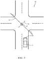
- FIG. 2is a top view of an intersection encountered by the system of FIG. 1 in accordance with one embodiment.
- FIGS. 3A and 3Bare images from a series-of-images rendered by the system of FIG. 1 in accordance with one embodiment.
- FIG. 1illustrates a non-limiting example of a traffic-light-detection system 10 , hereafter referred to as the system 10 .
- the system 10visually determines a light-state 18 (e.g. red, green yellow) of a traffic-light 20 proximate to, e.g. in front of, within fifty meters ( 50 m ) for example, an automated vehicle, e.g. a host-vehicle 12 .
- the system 10is able to determine the light-state 18 when the traffic-light 20 is moving, e.g. swinging from a cable 40 ( FIG. 2 ) that spans an intersection 22 .
- the light emitted by the traffic-light 20appears to vary from the perspective of the host-vehicle 12 as the direction of the bore-site of light emitted by the traffic-light 20 varies.
- the apparent variation in apparent-intensity and/or size of the illuminated light (e.g. red, green yellow) on the traffic-light 20may make it difficult for prior examples of visual traffic light detection systems to determine the light-state 18 of the traffic-light.
- the term automated vehiclemay apply to instances when the host-vehicle 12 is being operated in an automated-mode 14 , i.e. a fully autonomous mode, where a human-operator (not shown) of the host-vehicle 12 may do little more than designate a destination in order to operate the host-vehicle 12 .
- full automationis not a requirement. It is contemplated that the teachings presented herein are useful when the host-vehicle 12 is operated in a manual-mode 16 where the degree or level of automation may be little more than providing an audible or visual warning to the human-operator who is generally in control of the steering, accelerator, and brakes of the host-vehicle 12 .
- the system 10may merely warn the human-operator as needed to, for example, avoid ‘running’ a red-light, i.e. traveling through an intersection 22 ( FIG. 2 ) when the traffic-light 20 indicates that the host-vehicle 12 should stop.
- the system 10includes a camera 24 on a host-vehicle 12 .
- the camera 24may be a video-camera or a camera capable of taking periodically timed images. Whatever type is used, the camera 24 needs to be capable to render a series-of-images 26 of the traffic-light 20 .
- Those in the artwill recognize that there are a wide variety of commercially available cameras that are suitable for this application. If the camera 24 is used to determine a motion-pattern 34 of the traffic-light 20 if/when the traffic-light 20 is moving, it is preferable that the camera 24 has or is characterized by a minimum frame-rate, ten frames-per-second (10 fps) for example.
- the motion-pattern 34may be a characterization of the type of motion exhibited by the traffic-light 20 .
- the motion-pattern 34may be characterized as swinging forward-and-backward relative to the host-vehicle 12 , side-to-side (i.e. sideways or left-and-right) relative to the host-vehicle 12 , swinging diagonally relative to the host-vehicle 12 , oscillatory-rotating about a vertical-axis of the traffic-light 20 , oscillating vertically along the vertical-axis (bouncing), or any combination thereof.
- the details of how the motion-pattern 34 is determined and how the series-of-images 26 are analyzedwill be explained in more detail later.
- the system 10optionally includes a radar 28 on the host-vehicle 12 .
- a radar 28on the host-vehicle 12 .
- a variety of radar-devicesare commercially available for automotive applications that would be suitable to emit a radar-signal toward the traffic-light 20 and detect instances of radar-returns 30 reflected by, and/or returning from, the traffic-light 20 . If the radar 28 is used to determine a motion-pattern 34 of the traffic-light 20 when the traffic-light 20 is moving, it is preferable that the radar 28 has or is characterized by a minimum frame-rate, ten frames-per-second (10 fps) for example.
- the system 10includes a controller 32 in communication with the camera 24 , and the radar 28 if the radar 28 is provided or included in the configuration of the system 10 .
- the controller 32may include a processor (not specifically shown) such as a microprocessor or other control circuitry such as analog and/or digital control circuitry including an application specific integrated circuit (ASIC) for processing data as should be evident to those in the art.
- the controller 32may include memory (not specifically shown), including non-volatile memory, such as electrically erasable programmable read-only memory (EEPROM) for storing one or more routines, thresholds, and captured data.
- the one or more routinesmay be executed by the processor to perform steps for determining the motion-pattern 34 and the light-state 18 based on signals received by the controller 32 from the camera 24 and optionally the radar 28 as described herein.
- the controller 32may be configured to determine a motion-pattern 34 of the traffic-light 20 based on the series-of-images 26 , and then select a preferred-image 36 from the series-of-images 26 . If the traffic-light is not moving, then likely any or all of the images in the series-of-images 26 could be analyzed to determine the light-state 18 . Indeed, it is recognized that basing the determination of the light-state 18 on multiple images increases the confidence-level of the determination of the light-state 18 . However, when the traffic-light 20 is moving, the position of the illuminated light (red, green, yellow) in each image of the series-of-images 26 likely changes which can make it difficult to have a high confidence-level.
- the preferred-image 36 from the series-of-images 26may be characterized one or more of the images that shows, or was rendered when, a light-source 38 ( FIGS. 3A and 3B ) of the traffic-light 20 is characterized as being most directed at the camera 24 when/while the motion-pattern 34 indicates that the traffic-light 20 is moving. That is, the preferred-image 36 is selected from the series-of-images 26 as being the one or more images that is/are most likely to indicate the light-state 18 with high-confidence. It is recognized that if the motion-pattern 34 is relatively periodic, i.e. relatively predictable, then there may be multiple instances of the preferred-image 36 present in the series-of-images 26 that are temporally spaced apart in accordance with the periodicity of motion or oscillation of the traffic-light 20 .
- FIG. 2illustrates a non-limiting example of an intersection 22 equipped with a traffic-light 20 that is suspended above the intersection 22 by a cable 40 that is attached to poles at each end of the cable 40 .
- the traffic-light 20is moving or swinging with a motion-pattern 34 that can be characterized as swinging diagonally relative to a view-perspective of the host-vehicle 12 .
- FIGS. 3A and 3Bare non-limiting examples of images from the series-of-images 26 that may have been taken by the camera 24 from the perspective illustrated in FIG. 2 while the traffic-light was moving in accordance with the motion-pattern 34 illustrated in FIG. 2 .
- FIG. 3Amay be characterized as an instance of the preferred-image 36 because the light-source 38 , the green light in this example, is well-directed toward the camera 24 , i.e. is pointed almost directly at the camera 24 .
- FIG. 3Bmay be characterized as an instance of a discarded-image 44 from the series-of-images 26 because the light-source is not well-directed toward the camera 24 , i.e. is pointed away from the camera 24 .
- the motion-pattern 34is relatively periodic, then there may be multiple instances of the preferred-image 36 shown in FIG. 3A present in the series-of-images 26 that are temporally spaced apart and repeat or reoccur on a periodic basis. It follows that the multiple instances of the preferred-image 36 shown in FIG. 3A may be grouped together for image-processing to determine the light-state 18 based on multiple instances of the preferred-image 36 and thereby determine the light-state 18 with high-confidence.
- the system 10may include the radar 28 , so it follows that the controller 32 would be in communication with the camera 24 and the radar 28 .
- the controller 32may be configured to determine the motion-pattern 34 of the traffic-light 20 based on the radar-returns 30 , and then select the preferred-image 36 from the series-of-images 26 based on the motion-pattern 34 indicated by the radar 28 rather than what might be indicated by the camera 24 .
- information from both the camera 24 and the radar 28may be combined to determine which images of the series-of-images 26 is the preferred-image 36 or are the preferred-images.
- the radar-returns 30may be analyzed using a variety of techniques known to those in the radar arts to determine the motion-pattern 34 of the traffic-light 20 .
- one techniquemay be to determine, based on the radar-returns 30 , when a mid-point of a periodic motion occurs, and then designate the image from the series-of-images 26 that temporally coincides with the mid-point as the preferred-image 36 .
- the image that corresponds to the mid-pointis likely that shown in FIG. 3A , which corresponds to the position of the traffic-light shown in FIG. 2 . That is, it is believed that the mid-point is where the light-source 38 of the traffic-light 20 characterized as being most directed at the camera 24 .
- an end-point of the motion-pattern 34i.e.
- FIG. 3Ba point of maximum deflection away from the mid-point, may correspond to FIG. 3B .
- the series-of-images 26would likely include one or more images that is/are the opposite of FIG. 3B . That is, if FIG. 3B is characterized as the traffic-light 20 swinging toward and leftward relative to the camera 24 , then there is expected to be an opposite image in the series-of-images that shows the traffic-light 20 as swinging away-from and rightward relative to the camera 24 .
- One optionis to determine an apparent-size 46 of the light-source 38 in the series-of-images by, for example, counting the number of camera-pixels that detect the light-source 38 . It is recognized that counting the number of camera-pixels that detect the light-source 38 in each image of the series-of-images 26 will include tracking the position of where the light-source 38 appears in each of the images.
- counting the number of camera-pixels that detect the light-source 38 in each image of the series-of-images 26will include tracking the position of where the light-source 38 appears in each of the images.
- the preferred-image 36is then selected based on which of the images shows or renders the apparent-size 46 characterized as largest in the series-of-images 26 . That is, the preferred-image 36 is the image that has the greatest number of camera-pixels that detect the light-source 38 . In this example it may not be necessary to determine the particular type of motion, e.g. forward-and-backward, side-to-side, diagonal, oscillatory-rotating, bouncing. The effect of variation of the apparent-size 46 due to swinging if the traffic-light 20 is evident by examining FIGS. 3A and 3B .
- controller 32is configured to determine an apparent-intensity 48 of the light-source 38 in the series-of-images 26 .
- the traffic-light 20is characterized as being most directed at the camera 24 , it is expected that the apparent-intensity 48 of the light-source will be the greatest.
- the preferred-imageis then selected for having the apparent-intensity 48 characterized as greatest in images of the series-of-images 26 .
- the controller 32may be configured to define a bounding-box 50 about each image of the traffic-light 20 in the series-of-images 26 , and determine if the traffic-light 20 is moving and/or the motion-pattern 34 based on changes in a box-size of the bounding-box 50 over the series-of-images.
- the box-sizemay consist of, or include, a box-height, a box-width, a box-area, or any combination thereof. For example, if the motion is forward-and-backward relative to the camera 24 , the box-height would vary, but the box-width may be substantially unchanged.
- the selection of the preferred-image 36may be relatively critical to making a reliable determination of the light-state 18 because of the substantial variation in the apparent-intensity 48 .
- side-to-side motionmay cause greater variation in box-width and box-area when compared to variation in box-height.
- the selection which image or images are the preferred-image 36may not be critical to making a reliable determination of the light-state 18 .
- the controller 32may be advantageously further configured to determine when the motion-pattern 34 is such that an other-light 52 ( FIG. 3B ) may be periodically revealed to the camera 24 .
- the swinging of the traffic-light 20causes the red-light that is not directed to the host-vehicle 12 to be revealed to the camera 24 .
- the other-light 52could be a street-light (not shown) or advertisement-light (not shown) that is hidden behind the traffic-signal in FIG. 3A .
- Knowledge that the motion-pattern 34 is such that the other-light 52 may be periodically revealed to the camera 24may help to prevent confusion about the light-state 18 .
- the vehicle-operation block 54may erroneously elect to apply the brakes rather than continue through the intersection 22 .
- the controller 32may be advantageously further configured to determine a motion-period 56 of the motion-pattern 34 , where the motion-period 56 may correspond to the period of oscillation of the swinging-motion of the traffic-light 20 .
- the controller 32can predict which of future-images 58 rendered by the camera 24 will be selected as the preferred-image 36 . That is, rather than wait until a large number of images in the series-of-images 26 have been rendered and analyzed to select the preferred-image 36 , the motion-period 56 can be used to predict when the next instance of an image likely to be an instance of the preferred-image 36 will occur. This will allow the system 10 to more quickly and confidently determine that the light-state 18 has recently changed.
- the system 10may also include, or have access to via wireless communications, a digital-map 60 that indicates traffic-light-positions of various instances of the traffic-light 20 that the host-vehicle 12 may encounter.
- a traffic-light-detection system(the system 10 ), a controller 32 for the system 10 , and a method of operating the system 10 is provided.
- the system 10provides for more reliable and quicker determination of the light-state 18 of a traffic-light 20 when the traffic-light 20 is swinging or otherwise moving relative to a host-vehicle 12 equipped with the system 10 .
Landscapes
- Engineering & Computer Science (AREA)
- Radar, Positioning & Navigation (AREA)
- Remote Sensing (AREA)
- Physics & Mathematics (AREA)
- General Physics & Mathematics (AREA)
- Computer Networks & Wireless Communication (AREA)
- Electromagnetism (AREA)
- Mechanical Engineering (AREA)
- Multimedia (AREA)
- Theoretical Computer Science (AREA)
- Traffic Control Systems (AREA)
Abstract
Description
Claims (13)
Priority Applications (4)
| Application Number | Priority Date | Filing Date | Title |
|---|---|---|---|
| US15/638,546US10525903B2 (en) | 2017-06-30 | 2017-06-30 | Moving traffic-light detection system for an automated vehicle |
| CN201880043576.2ACN110831832B (en) | 2017-06-30 | 2018-06-28 | Mobile Traffic Light Detection System for Autonomous Vehicles |
| PCT/US2018/039940WO2019006084A1 (en) | 2017-06-30 | 2018-06-28 | Moving traffic-light detection system for an automated vehicle |
| EP18824682.1AEP3621863B1 (en) | 2017-06-30 | 2018-06-28 | Moving traffic-light detection system for an automated vehicle |
Applications Claiming Priority (1)
| Application Number | Priority Date | Filing Date | Title |
|---|---|---|---|
| US15/638,546US10525903B2 (en) | 2017-06-30 | 2017-06-30 | Moving traffic-light detection system for an automated vehicle |
Publications (2)
| Publication Number | Publication Date |
|---|---|
| US20190001900A1 US20190001900A1 (en) | 2019-01-03 |
| US10525903B2true US10525903B2 (en) | 2020-01-07 |
Family
ID=64735276
Family Applications (1)
| Application Number | Title | Priority Date | Filing Date |
|---|---|---|---|
| US15/638,546Active2038-07-14US10525903B2 (en) | 2017-06-30 | 2017-06-30 | Moving traffic-light detection system for an automated vehicle |
Country Status (4)
| Country | Link |
|---|---|
| US (1) | US10525903B2 (en) |
| EP (1) | EP3621863B1 (en) |
| CN (1) | CN110831832B (en) |
| WO (1) | WO2019006084A1 (en) |
Cited By (3)
| Publication number | Priority date | Publication date | Assignee | Title |
|---|---|---|---|---|
| US10852743B2 (en)* | 2018-09-07 | 2020-12-01 | GM Global Technology Operations LLC | Multimodal multi-technique signal fusion system for autonomous vehicle |
| US11527156B2 (en)* | 2020-08-03 | 2022-12-13 | Toyota Research Institute, Inc. | Light emitting component-wise traffic light state, signal, and transition estimator |
| US11681780B2 (en)* | 2020-09-30 | 2023-06-20 | Nissan North America, Inc. | Annotation and mapping for vehicle operation in low-confidence object detection conditions |
Families Citing this family (2)
| Publication number | Priority date | Publication date | Assignee | Title |
|---|---|---|---|---|
| CN111882899B (en)* | 2020-07-24 | 2021-10-22 | 北京小马慧行科技有限公司 | Method, device and system for determining the position of a traffic signal |
| CN116887488B (en)* | 2023-09-07 | 2023-12-12 | 中建照明有限公司 | Traffic lighting control system for urban road and control method thereof |
Citations (9)
| Publication number | Priority date | Publication date | Assignee | Title |
|---|---|---|---|---|
| US7398076B2 (en)* | 2004-07-09 | 2008-07-08 | Aisin Aw Co., Ltd. | Method of producing traffic signal information, method of providing traffic signal information, and navigation apparatus |
| US20100033571A1 (en) | 2006-09-28 | 2010-02-11 | Pioneer Corporation | Traffic information detector, traffic information detecting method, traffic information detecting program, and recording medium |
| US20120288138A1 (en) | 2011-05-10 | 2012-11-15 | GM Global Technology Operations LLC | System and method for traffic signal detection |
| WO2013147994A1 (en) | 2012-03-26 | 2013-10-03 | Google Inc. | A robust method for detecting traffic signals and their associated states |
| US8761991B1 (en) | 2012-04-09 | 2014-06-24 | Google Inc. | Use of uncertainty regarding observations of traffic intersections to modify behavior of a vehicle |
| US8831849B2 (en)* | 2012-02-13 | 2014-09-09 | Toyota Motor Engineering & Manufacturing North America, Inc. | System and method for traffic signal recognition |
| US20150210277A1 (en) | 2014-01-30 | 2015-07-30 | Mobileye Vision Technologies Ltd. | Systems and methods for detecting traffic lights |
| US9779314B1 (en)* | 2014-08-21 | 2017-10-03 | Waymo Llc | Vision-based detection and classification of traffic lights |
| US9990548B2 (en)* | 2016-03-09 | 2018-06-05 | Uber Technologies, Inc. | Traffic signal analysis system |
Family Cites Families (6)
| Publication number | Priority date | Publication date | Assignee | Title |
|---|---|---|---|---|
| US8559673B2 (en)* | 2010-01-22 | 2013-10-15 | Google Inc. | Traffic signal mapping and detection |
| US8793046B2 (en)* | 2012-06-01 | 2014-07-29 | Google Inc. | Inferring state of traffic signal and other aspects of a vehicle's environment based on surrogate data |
| US9881220B2 (en)* | 2013-10-25 | 2018-01-30 | Magna Electronics Inc. | Vehicle vision system utilizing communication system |
| RU2643861C1 (en)* | 2014-03-10 | 2018-02-06 | Ниссан Мотор Ко., Лтд. | Device for detecting light signals and method for detecting light signals |
| BR112016020884B1 (en)* | 2014-03-10 | 2022-01-11 | Nissan Motor Co. Ltd. | TRAFFIC SIGN DETECTION DEVICE AND TRAFFIC SIGN DETECTION METHOD |
| JP6447729B2 (en)* | 2015-07-13 | 2019-01-16 | 日産自動車株式会社 | Signal recognition device and signal recognition method |
- 2017
- 2017-06-30USUS15/638,546patent/US10525903B2/enactiveActive
- 2018
- 2018-06-28CNCN201880043576.2Apatent/CN110831832B/enactiveActive
- 2018-06-28WOPCT/US2018/039940patent/WO2019006084A1/ennot_activeCeased
- 2018-06-28EPEP18824682.1Apatent/EP3621863B1/enactiveActive
Patent Citations (14)
| Publication number | Priority date | Publication date | Assignee | Title |
|---|---|---|---|---|
| US7398076B2 (en)* | 2004-07-09 | 2008-07-08 | Aisin Aw Co., Ltd. | Method of producing traffic signal information, method of providing traffic signal information, and navigation apparatus |
| US20100033571A1 (en) | 2006-09-28 | 2010-02-11 | Pioneer Corporation | Traffic information detector, traffic information detecting method, traffic information detecting program, and recording medium |
| US20120288138A1 (en) | 2011-05-10 | 2012-11-15 | GM Global Technology Operations LLC | System and method for traffic signal detection |
| US8831849B2 (en)* | 2012-02-13 | 2014-09-09 | Toyota Motor Engineering & Manufacturing North America, Inc. | System and method for traffic signal recognition |
| US9145140B2 (en)* | 2012-03-26 | 2015-09-29 | Google Inc. | Robust method for detecting traffic signals and their associated states |
| WO2013147994A1 (en) | 2012-03-26 | 2013-10-03 | Google Inc. | A robust method for detecting traffic signals and their associated states |
| US8761991B1 (en) | 2012-04-09 | 2014-06-24 | Google Inc. | Use of uncertainty regarding observations of traffic intersections to modify behavior of a vehicle |
| US20150210277A1 (en) | 2014-01-30 | 2015-07-30 | Mobileye Vision Technologies Ltd. | Systems and methods for detecting traffic lights |
| US9248832B2 (en)* | 2014-01-30 | 2016-02-02 | Mobileye Vision Technologies Ltd. | Systems and methods for detecting traffic signal details |
| US9779314B1 (en)* | 2014-08-21 | 2017-10-03 | Waymo Llc | Vision-based detection and classification of traffic lights |
| US9892332B1 (en)* | 2014-08-21 | 2018-02-13 | Waymo Llc | Vision-based detection and classification of traffic lights |
| US10108868B1 (en)* | 2014-08-21 | 2018-10-23 | Waymo Llc | Vision-based detection and classification of traffic lights |
| US10346696B1 (en)* | 2014-08-21 | 2019-07-09 | Waymo Llc | Vision-based detection and classification of traffic lights |
| US9990548B2 (en)* | 2016-03-09 | 2018-06-05 | Uber Technologies, Inc. | Traffic signal analysis system |
Cited By (5)
| Publication number | Priority date | Publication date | Assignee | Title |
|---|---|---|---|---|
| US10852743B2 (en)* | 2018-09-07 | 2020-12-01 | GM Global Technology Operations LLC | Multimodal multi-technique signal fusion system for autonomous vehicle |
| US20210048830A1 (en)* | 2018-09-07 | 2021-02-18 | GM Global Technology Operations LLC | Multimodal multi-technique signal fusion system for autonomous vehicle |
| US11873003B2 (en)* | 2018-09-07 | 2024-01-16 | GM Global Technology Operations LLC | Multimodal multi-technique signal fusion system for autonomous vehicle |
| US11527156B2 (en)* | 2020-08-03 | 2022-12-13 | Toyota Research Institute, Inc. | Light emitting component-wise traffic light state, signal, and transition estimator |
| US11681780B2 (en)* | 2020-09-30 | 2023-06-20 | Nissan North America, Inc. | Annotation and mapping for vehicle operation in low-confidence object detection conditions |
Also Published As
| Publication number | Publication date |
|---|---|
| US20190001900A1 (en) | 2019-01-03 |
| EP3621863B1 (en) | 2024-10-16 |
| EP3621863A4 (en) | 2021-03-10 |
| WO2019006084A1 (en) | 2019-01-03 |
| CN110831832B (en) | 2022-12-20 |
| EP3621863A1 (en) | 2020-03-18 |
| CN110831832A (en) | 2020-02-21 |
Similar Documents
| Publication | Publication Date | Title |
|---|---|---|
| EP3621863B1 (en) | Moving traffic-light detection system for an automated vehicle | |
| US11802967B2 (en) | Data fusion system for a vehicle equipped with unsynchronized perception sensors | |
| CN102376166B (en) | For identifying the apparatus and method of road signs in motor vehicles | |
| US10235875B2 (en) | Vehicle communication system for cloud-hosting sensor-data | |
| JP4603970B2 (en) | Road marking line detection device | |
| US10099614B2 (en) | Vision system for vehicle | |
| JP5399027B2 (en) | A device having a system capable of capturing a stereoscopic image to assist driving of an automobile | |
| EP3239738B1 (en) | Prioritized sensor data processing using map information for automated vehicles | |
| US11488476B2 (en) | Detection system and method | |
| EP1930863A2 (en) | Detecting and recognizing traffic signs | |
| US10676103B2 (en) | Object position history playback for automated vehicle transition from autonomous-mode to manual-mode | |
| US20140044311A1 (en) | Neighboring vehicle detecting apparatus | |
| CN107408288B (en) | Warning device, warning method, and warning program | |
| US20060220912A1 (en) | Sensing apparatus for vehicles | |
| KR102387774B1 (en) | Variable range and frame-rate radar operation for automated vehicles | |
| JP2010510935A (en) | How to automatically control long-distance lights | |
| US9635271B2 (en) | Vision-based scene detection | |
| EP4044151B1 (en) | Automated vehicle control strategy for pedestrian crowds | |
| WO2017209907A2 (en) | Roadway-infrastructure-maintenance system using automated vehicles | |
| WO2013035828A1 (en) | Device and method for predicting turning of vehicle | |
| JP6392037B2 (en) | Automated traveling management system and automated traveling management method | |
| WO2020105527A1 (en) | Image analysis device, image analysis system, and control program | |
| US10848718B2 (en) | Vehicle sensor configuration based on map data | |
| JP2011227551A (en) | Meander driving detection device for vehicle | |
| US20200410256A1 (en) | Method and Device for Detecting Lanes, Driver Assistance System and Vehicle |
Legal Events
| Date | Code | Title | Description |
|---|---|---|---|
| AS | Assignment | Owner name:DELPHI TECHNOLOGIES, INC., MICHIGAN Free format text:ASSIGNMENT OF ASSIGNORS INTEREST;ASSIGNORS:LAUR, MICHAEL H.;HILNBRAND, BRIAN R.;SZABO, RONALD J.;SIGNING DATES FROM 20170627 TO 20170628;REEL/FRAME:042871/0653 | |
| STPP | Information on status: patent application and granting procedure in general | Free format text:DOCKETED NEW CASE - READY FOR EXAMINATION | |
| AS | Assignment | Owner name:APTIV TECHNOLOGIES LIMITED, BARBADOS Free format text:ASSIGNMENT OF ASSIGNORS INTEREST;ASSIGNOR:DELPHI TECHNOLOGIES INC.;REEL/FRAME:047153/0902 Effective date:20180101 | |
| STPP | Information on status: patent application and granting procedure in general | Free format text:NOTICE OF ALLOWANCE MAILED -- APPLICATION RECEIVED IN OFFICE OF PUBLICATIONS | |
| STPP | Information on status: patent application and granting procedure in general | Free format text:PUBLICATIONS -- ISSUE FEE PAYMENT VERIFIED | |
| STCF | Information on status: patent grant | Free format text:PATENTED CASE | |
| MAFP | Maintenance fee payment | Free format text:PAYMENT OF MAINTENANCE FEE, 4TH YEAR, LARGE ENTITY (ORIGINAL EVENT CODE: M1551); ENTITY STATUS OF PATENT OWNER: LARGE ENTITY Year of fee payment:4 | |
| AS | Assignment | Owner name:APTIV TECHNOLOGIES (2) S.A R.L., LUXEMBOURG Free format text:ENTITY CONVERSION;ASSIGNOR:APTIV TECHNOLOGIES LIMITED;REEL/FRAME:066746/0001 Effective date:20230818 Owner name:APTIV MANUFACTURING MANAGEMENT SERVICES S.A R.L., LUXEMBOURG Free format text:MERGER;ASSIGNOR:APTIV TECHNOLOGIES (2) S.A R.L.;REEL/FRAME:066566/0173 Effective date:20231005 Owner name:APTIV TECHNOLOGIES AG, SWITZERLAND Free format text:ASSIGNMENT OF ASSIGNORS INTEREST;ASSIGNOR:APTIV MANUFACTURING MANAGEMENT SERVICES S.A R.L.;REEL/FRAME:066551/0219 Effective date:20231006 |