US10525257B2 - Orientation marker for implantable leads and leads, systems, and methods utilizing the orientation marker - Google Patents
Orientation marker for implantable leads and leads, systems, and methods utilizing the orientation markerDownload PDFInfo
- Publication number
- US10525257B2 US10525257B2US15/729,424US201715729424AUS10525257B2US 10525257 B2US10525257 B2US 10525257B2US 201715729424 AUS201715729424 AUS 201715729424AUS 10525257 B2US10525257 B2US 10525257B2
- Authority
- US
- United States
- Prior art keywords
- lead
- longitudinal
- longitudinal band
- lead body
- ring
- Prior art date
- Legal status (The legal status is an assumption and is not a legal conclusion. Google has not performed a legal analysis and makes no representation as to the accuracy of the status listed.)
- Active
Links
- 239000003550markerSubstances0.000titleclaimsabstractdescription69
- 238000000034methodMethods0.000titledescription8
- 230000000638stimulationEffects0.000claimsabstractdescription59
- 239000000463materialSubstances0.000claimsabstractdescription15
- 210000004556brainAnatomy0.000description14
- 210000001519tissueAnatomy0.000description10
- 210000003205muscleAnatomy0.000description7
- 210000002569neuronAnatomy0.000description7
- 238000003384imaging methodMethods0.000description6
- 239000004020conductorSubstances0.000description5
- 229910052751metalInorganic materials0.000description5
- 239000002184metalSubstances0.000description5
- 230000006854communicationEffects0.000description4
- 238000004891communicationMethods0.000description4
- 210000000278spinal cordAnatomy0.000description4
- 238000002591computed tomographyMethods0.000description3
- 238000013461designMethods0.000description3
- 238000005259measurementMethods0.000description3
- KDLHZDBZIXYQEI-UHFFFAOYSA-NPalladiumChemical compound[Pd]KDLHZDBZIXYQEI-UHFFFAOYSA-N0.000description2
- 206010044565TremorDiseases0.000description2
- 239000000956alloySubstances0.000description2
- 229910045601alloyInorganic materials0.000description2
- 208000022371chronic pain syndromeDiseases0.000description2
- 238000013170computed tomography imagingMethods0.000description2
- 208000037265diseases, disorders, signs and symptomsDiseases0.000description2
- 230000001788irregularEffects0.000description2
- 210000005036nerveAnatomy0.000description2
- 230000007383nerve stimulationEffects0.000description2
- 210000000578peripheral nerveAnatomy0.000description2
- BASFCYQUMIYNBI-UHFFFAOYSA-NplatinumChemical compound[Pt]BASFCYQUMIYNBI-UHFFFAOYSA-N0.000description2
- 230000004044responseEffects0.000description2
- 230000001225therapeutic effectEffects0.000description2
- 238000011282treatmentMethods0.000description2
- 206010021639IncontinenceDiseases0.000description1
- 206010033799ParalysisDiseases0.000description1
- 229910000566Platinum-iridium alloyInorganic materials0.000description1
- 239000004698PolyethyleneSubstances0.000description1
- 229920002396PolyureaPolymers0.000description1
- RTAQQCXQSZGOHL-UHFFFAOYSA-NTitaniumChemical compound[Ti]RTAQQCXQSZGOHL-UHFFFAOYSA-N0.000description1
- 210000000683abdominal cavityAnatomy0.000description1
- 230000008901benefitEffects0.000description1
- 230000007175bidirectional communicationEffects0.000description1
- 239000000560biocompatible materialSubstances0.000description1
- 210000005013brain tissueAnatomy0.000description1
- 210000001217buttockAnatomy0.000description1
- 238000005266castingMethods0.000description1
- 210000003109clavicleAnatomy0.000description1
- 230000001112coagulating effectEffects0.000description1
- 239000002131composite materialSubstances0.000description1
- 230000008878couplingEffects0.000description1
- 238000010168coupling processMethods0.000description1
- 238000005859coupling reactionMethods0.000description1
- 201000010099diseaseDiseases0.000description1
- 208000037765diseases and disordersDiseases0.000description1
- 208000035475disorderDiseases0.000description1
- 238000005553drillingMethods0.000description1
- 210000001951dura materAnatomy0.000description1
- 210000003414extremityAnatomy0.000description1
- 238000002513implantationMethods0.000description1
- 238000011835investigationMethods0.000description1
- 229910052741iridiumInorganic materials0.000description1
- GKOZUEZYRPOHIO-UHFFFAOYSA-Niridium atomChemical compound[Ir]GKOZUEZYRPOHIO-UHFFFAOYSA-N0.000description1
- 238000003754machiningMethods0.000description1
- 238000004519manufacturing processMethods0.000description1
- 150000002739metalsChemical class0.000description1
- 238000012986modificationMethods0.000description1
- 230000004048modificationEffects0.000description1
- 238000000465mouldingMethods0.000description1
- 230000001537neural effectEffects0.000description1
- 210000000056organAnatomy0.000description1
- 229910052763palladiumInorganic materials0.000description1
- XSKIUFGOTYHDLC-UHFFFAOYSA-Npalladium rhodiumChemical compound[Rh].[Pd]XSKIUFGOTYHDLC-UHFFFAOYSA-N0.000description1
- 229920003023plasticPolymers0.000description1
- 239000004033plasticSubstances0.000description1
- 229910052697platinumInorganic materials0.000description1
- HWLDNSXPUQTBOD-UHFFFAOYSA-Nplatinum-iridium alloyChemical class[Ir].[Pt]HWLDNSXPUQTBOD-UHFFFAOYSA-N0.000description1
- -1polyethylenePolymers0.000description1
- 229920000573polyethylenePolymers0.000description1
- 229920001296polysiloxanePolymers0.000description1
- 229920002635polyurethanePolymers0.000description1
- 239000004814polyurethaneSubstances0.000description1
- 229920003226polyurethane ureaPolymers0.000description1
- 230000004043responsivenessEffects0.000description1
- 210000003625skullAnatomy0.000description1
- 208000020431spinal cord injuryDiseases0.000description1
- 230000004936stimulating effectEffects0.000description1
- 230000008685targetingEffects0.000description1
- 230000002123temporal effectEffects0.000description1
- 238000012360testing methodMethods0.000description1
- 238000002560therapeutic procedureMethods0.000description1
- 229910052719titaniumInorganic materials0.000description1
- 239000010936titaniumSubstances0.000description1
- WFKWXMTUELFFGS-UHFFFAOYSA-NtungstenChemical compound[W]WFKWXMTUELFFGS-UHFFFAOYSA-N0.000description1
- 229910052721tungstenInorganic materials0.000description1
- 239000010937tungstenSubstances0.000description1
Images


Classifications
- A—HUMAN NECESSITIES
- A61—MEDICAL OR VETERINARY SCIENCE; HYGIENE
- A61N—ELECTROTHERAPY; MAGNETOTHERAPY; RADIATION THERAPY; ULTRASOUND THERAPY
- A61N1/00—Electrotherapy; Circuits therefor
- A61N1/02—Details
- A61N1/04—Electrodes
- A61N1/05—Electrodes for implantation or insertion into the body, e.g. heart electrode
- A—HUMAN NECESSITIES
- A61—MEDICAL OR VETERINARY SCIENCE; HYGIENE
- A61B—DIAGNOSIS; SURGERY; IDENTIFICATION
- A61B90/00—Instruments, implements or accessories specially adapted for surgery or diagnosis and not covered by any of the groups A61B1/00 - A61B50/00, e.g. for luxation treatment or for protecting wound edges
- A61B90/39—Markers, e.g. radio-opaque or breast lesions markers
- A—HUMAN NECESSITIES
- A61—MEDICAL OR VETERINARY SCIENCE; HYGIENE
- A61N—ELECTROTHERAPY; MAGNETOTHERAPY; RADIATION THERAPY; ULTRASOUND THERAPY
- A61N1/00—Electrotherapy; Circuits therefor
- A61N1/02—Details
- A61N1/04—Electrodes
- A61N1/05—Electrodes for implantation or insertion into the body, e.g. heart electrode
- A61N1/0551—Spinal or peripheral nerve electrodes
- A—HUMAN NECESSITIES
- A61—MEDICAL OR VETERINARY SCIENCE; HYGIENE
- A61N—ELECTROTHERAPY; MAGNETOTHERAPY; RADIATION THERAPY; ULTRASOUND THERAPY
- A61N1/00—Electrotherapy; Circuits therefor
- A61N1/18—Applying electric currents by contact electrodes
- A61N1/32—Applying electric currents by contact electrodes alternating or intermittent currents
- A61N1/36—Applying electric currents by contact electrodes alternating or intermittent currents for stimulation
- A61N1/36003—Applying electric currents by contact electrodes alternating or intermittent currents for stimulation of motor muscles, e.g. for walking assistance
- A—HUMAN NECESSITIES
- A61—MEDICAL OR VETERINARY SCIENCE; HYGIENE
- A61N—ELECTROTHERAPY; MAGNETOTHERAPY; RADIATION THERAPY; ULTRASOUND THERAPY
- A61N1/00—Electrotherapy; Circuits therefor
- A61N1/18—Applying electric currents by contact electrodes
- A61N1/32—Applying electric currents by contact electrodes alternating or intermittent currents
- A61N1/36—Applying electric currents by contact electrodes alternating or intermittent currents for stimulation
- A61N1/36007—Applying electric currents by contact electrodes alternating or intermittent currents for stimulation of urogenital or gastrointestinal organs, e.g. for incontinence control
- A—HUMAN NECESSITIES
- A61—MEDICAL OR VETERINARY SCIENCE; HYGIENE
- A61N—ELECTROTHERAPY; MAGNETOTHERAPY; RADIATION THERAPY; ULTRASOUND THERAPY
- A61N1/00—Electrotherapy; Circuits therefor
- A61N1/18—Applying electric currents by contact electrodes
- A61N1/32—Applying electric currents by contact electrodes alternating or intermittent currents
- A61N1/36—Applying electric currents by contact electrodes alternating or intermittent currents for stimulation
- A61N1/3605—Implantable neurostimulators for stimulating central or peripheral nerve system
- A—HUMAN NECESSITIES
- A61—MEDICAL OR VETERINARY SCIENCE; HYGIENE
- A61B—DIAGNOSIS; SURGERY; IDENTIFICATION
- A61B90/00—Instruments, implements or accessories specially adapted for surgery or diagnosis and not covered by any of the groups A61B1/00 - A61B50/00, e.g. for luxation treatment or for protecting wound edges
- A61B90/39—Markers, e.g. radio-opaque or breast lesions markers
- A61B2090/3966—Radiopaque markers visible in an X-ray image
- A—HUMAN NECESSITIES
- A61—MEDICAL OR VETERINARY SCIENCE; HYGIENE
- A61N—ELECTROTHERAPY; MAGNETOTHERAPY; RADIATION THERAPY; ULTRASOUND THERAPY
- A61N1/00—Electrotherapy; Circuits therefor
- A61N1/02—Details
- A61N1/04—Electrodes
- A61N1/05—Electrodes for implantation or insertion into the body, e.g. heart electrode
- A61N1/0526—Head electrodes
- A61N1/0529—Electrodes for brain stimulation
- A61N1/0534—Electrodes for deep brain stimulation
- A—HUMAN NECESSITIES
- A61—MEDICAL OR VETERINARY SCIENCE; HYGIENE
- A61N—ELECTROTHERAPY; MAGNETOTHERAPY; RADIATION THERAPY; ULTRASOUND THERAPY
- A61N1/00—Electrotherapy; Circuits therefor
- A61N1/18—Applying electric currents by contact electrodes
- A61N1/32—Applying electric currents by contact electrodes alternating or intermittent currents
- A61N1/36—Applying electric currents by contact electrodes alternating or intermittent currents for stimulation
- A61N1/372—Arrangements in connection with the implantation of stimulators
- A61N1/37211—Means for communicating with stimulators
- A61N1/37235—Aspects of the external programmer
Definitions
- the present inventionis directed to the area of implantable electrical stimulation systems and methods of making and using the systems.
- the present inventionis also directed to systems and methods for determining the orientation of an implanted electrical stimulation lead.
- Implantable electrical stimulation systemshave proven therapeutic in a variety of diseases and disorders.
- spinal cord stimulation systemshave been used as a therapeutic modality for the treatment of chronic pain syndromes.
- Peripheral nerve stimulationhas been used to treat chronic pain syndrome and incontinence, with a number of other applications under investigation.
- Functional electrical stimulation systemshave been applied to restore some functionality to paralyzed extremities in spinal cord injury patients.
- Stimulation of the brainsuch as deep brain stimulation, can be used to treat a variety of diseases or disorders.
- a stimulatorcan include a control module (with a pulse generator), one or more leads, and an array of stimulator electrodes on each lead.
- the stimulator electrodesare in contact with or near the nerves, muscles, or other tissue to be stimulated.
- the pulse generator in the control modulegenerates electrical pulses that are delivered by the electrodes to body tissue.
- One embodimentis an implantable electrical stimulation lead that includes a lead body having a perimeter, a distal portion. and proximal portion; terminals disposed along the proximal portion of the lead body; electrodes disposed along the distal portion of the lead body, the electrodes including at least one segmented electrode, where at least one of the segmented electrodes extends around no more than 50% of the perimeter of the lead body; and an asymmetric marker disposed along the distal portion of the lead body and including a first ring and a longitudinal band extending longitudinally from the first ring and extending around no more than 80% of the perimeter of the lead body.
- the asymmetric marker and lead bodyare formed of different materials that are distinguishable from each other in the radiological images.
- the markeris arranged on the lead body so that a rotational orientation of the lead when implanted can be determined radiologically by observation of the marker.
- the first ringhas a slit through the ring.
- the markerfurther includes a second ring, wherein the longitudinal band extends between the first and second rings.
- the first or second ring (or both rings)include a slit through that ring.
- the markerfurther includes a longitudinal extension extending longitudinally from the first ring away from the longitudinal band, wherein the longitudinal extension extends around no more than 80% of the perimeter of the lead body.
- the longitudinal bandextends distally from the first ring and the longitudinal extension extends proximally from the first ring.
- an implantable electrical stimulation leadincluding a lead body having a perimeter, a distal portion. and proximal portion; a plurality of terminals disposed along the proximal portion of the lead body; electrodes disposed along the distal portion of the lead body, the electrodes including at least one segmented electrode, wherein at least one of the segmented electrodes extends around no more than 50% of the perimeter of the lead body; and an asymmetric marker disposed along the distal portion of the lead body and including a longitudinal band and a longitudinal extension extending longitudinally away from the longitudinal band, wherein each of the longitudinal band and the longitudinal extension individually extend around no more than 80% of the perimeter of the lead body, wherein the longitudinal band and the longitudinal extension are circumferentially offset from each other, wherein the asymmetric marker and lead body are formed of different materials that are distinguishable from each other in the radiological images, wherein the marker is arranged on the lead body so that a rotational orientation of the lead when implanted can be determined radiologically by observation of the marker.
- both the longitudinal band and the longitudinal extensionextend around no more than 30% of the perimeter of the lead body. In at least some embodiments, the longitudinal band and the longitudinal extension are circumferentially offset from each other. In at least some embodiments, the longitudinal band and the longitudinal extension differ in circumferential width by at least 10% of the circumferential width of the longitudinal band. In at least some embodiments, the longitudinal band and the longitudinal extension differ in longitudinal length by at least 10% of the longitudinal length of the longitudinal band.
- the longitudinal bandextends around no more than 30% of the perimeter of the lead body.
- a circumferential width of the longitudinal bandvaries along a longitudinal length of the longitudinal band.
- the longitudinal bandhas a first end coupled to the first ring and a second end spaced apart longitudinally from the first end, wherein the circumferential width is narrowest at a position between the first end and the second end.
- the longitudinal bandhas a first end coupled to the first ring and a second end spaced apart longitudinally from the first end, wherein the circumferential width is widest at a position between the first end and the second end.
- the longitudinal bandhas two longitudinal edges extending longitudinally away from the first ring, wherein at least one of those longitudinal edges is not straight. In at least some embodiments, both of the longitudinal edges are not straight. In at least some embodiments, the longitudinal band defines a notch in the longitudinal band. In at least some embodiments, the longitudinal band is aligned with at least one of the segmented electrodes.
- Another embodimentis an electrical stimulation system that includes any of the leads described above and a control module coupleable to the lead, the control module including a housing, and an electronic subassembly disposed in the housing.
- the systemfurther includes a lead extension coupleable between the lead and the control module.
- FIG. 1is a schematic view of one embodiment of an electrical stimulation system, according to the invention.
- FIG. 2is a schematic side view of one embodiment of an electrical stimulation lead, according to the invention.
- FIG. 4Ais a schematic side view of a second embodiment of an asymmetric marker, according to the invention.
- FIG. 4Bis a schematic rotated view of the asymmetric marker of FIG. 4A , according to the invention.
- FIG. 4Cis a schematic perspective view of the asymmetric marker of FIG. 4A , according to the invention.
- FIG. 4Dis a schematic perspective view of a third embodiment of an asymmetric marker, according to the invention.
- FIG. 5Ais a schematic side view of a fourth embodiment of an asymmetric marker, according to the invention.
- FIG. 5Bis a schematic rotated view of the asymmetric marker of FIG. 5A , according to the invention.
- FIG. 5Cis a schematic perspective view of the asymmetric marker of FIG. 5A , according to the invention.
- FIG. 5Dis a schematic perspective view of a fifth embodiment of an asymmetric marker, according to the invention.
- FIG. 5Eis a schematic side view of a sixth embodiment of an asymmetric marker, according to the invention.
- FIG. 5Fis a schematic side view of a seventh embodiment of an asymmetric marker, according to the invention.
- FIG. 6Ais a schematic side view of an eighth embodiment of an asymmetric marker, according to the invention.
- FIG. 6Bis a schematic rotated view of the asymmetric marker of FIG. 6A , according to the invention.
- FIG. 6Cis a schematic perspective view of the asymmetric marker of FIG. 6A , according to the invention.
- FIG. 6Dis a schematic perspective view of a ninth embodiment of an asymmetric marker, according to the invention.
- the present inventionis directed to the area of implantable electrical stimulation systems and methods of making and using the systems.
- the present inventionis also directed to systems and methods for determining the orientation of an implanted electrical stimulation lead.
- Suitable implantable electrical stimulation systemsinclude, but are not limited to, a least one lead with one or more electrodes disposed on a distal end of the lead and one or more terminals disposed on one or more proximal ends of the lead.
- Leadsinclude, for example, percutaneous leads, paddle leads, cuff leads, or any other arrangement of electrodes on a lead. Examples of electrical stimulation systems with leads are found in, for example, U.S. Pat. Nos.
- 2007/01500362009/0187222; 2009/0276021; 2010/0076535; 2010/0268298; 2011/0005069; 2011/0004267; 2011/0078900; 2011/0130817; 2011/0130818; 2011/0238129; 2011/0313500; 2012/0016378; 2012/0046710; 2012/0071949; 2012/0165911; 2012/0197375; 2012/0203316; 2012/0203320; 2012/0203321; 2012/0316615; 2013/0105071; and 2013/0197602, all of which are incorporated by reference in their entirety.
- a percutaneous leadwill be exemplified, but it will be understood that the methods and systems described herein are also applicable to paddle leads and other leads.
- a percutaneous lead for electrical stimulation(for example, deep brain or spinal cord stimulation) includes stimulation electrodes that can be ring electrodes, segmented electrodes that extend only partially around the perimeter of the lead, or any other type of electrode, or any combination thereof.
- the segmented electrodescan be provided in sets of electrodes, with each set having electrodes circumferentially distributed about the lead at a particular longitudinal position.
- the leadsare described herein relative to use for deep brain stimulation, but it will be understood that any of the leads can be used for applications other than deep brain stimulation, including spinal cord stimulation, peripheral nerve stimulation, or stimulation of other nerves, muscles, and tissues.
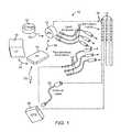
- an electrical stimulation system 10includes one or more stimulation leads 12 and an implantable pulse generator (IPG) 14 .
- the system 10can also include one or more of an external remote control (RC) 16 , a clinician's programmer (CP) 18 , an external trial stimulator (ETS) 20 , or an external charger 22 .
- RCremote control
- CPclinician's programmer
- ETSexternal trial stimulator
- the IPG 14is physically connected, optionally via one or more lead extensions 24 , to the stimulation lead(s) 12 .
- Each leadcarries multiple electrodes 26 arranged in an array.
- the IPG 14includes pulse generation circuitry that delivers electrical stimulation energy in the form of, for example, a pulsed electrical waveform (i.e., a temporal series of electrical pulses) to the electrode array 26 in accordance with a set of stimulation parameters.
- the implantable pulse generatorcan be implanted into a patient's body, for example, below the patient's clavicle area or within the patient's buttocks or abdominal cavity.
- the implantable pulse generatorcan have eight stimulation channels which may be independently programmable to control the magnitude of the current stimulus from each channel.
- the implantable pulse generatorcan have more or fewer than eight stimulation channels (e.g., 4-, 6-, 16-, 32-, or more stimulation channels).
- the implantable pulse generatorcan have one, two, three, four, or more connector ports, for receiving the terminals of the leads.
- the ETS 20may also be physically connected, optionally via the percutaneous lead extensions 28 and external cable 30 , to the stimulation leads 12 .
- the ETS 20which may have similar pulse generation circuitry as the IPG 14 , also delivers electrical stimulation energy in the form of, for example, a pulsed electrical waveform to the electrode array 26 in accordance with a set of stimulation parameters.
- One difference between the ETS 20 and the IPG 14is that the ETS 20 is often a non-implantable device that is used on a trial basis after the neurostimulation leads 12 have been implanted and prior to implantation of the IPG 14 , to test the responsiveness of the stimulation that is to be provided. Any functions described herein with respect to the IPG 14 can likewise be performed with respect to the ETS 20 .
- the RC 16may be used to telemetrically communicate with or control the IPG 14 or ETS 20 via a uni- or bi-directional wireless communications link 32 . Once the IPG 14 and neurostimulation leads 12 are implanted, the RC 16 may be used to telemetrically communicate with or control the IPG 14 via a uni- or bi-directional communications link 34 . Such communication or control allows the IPG 14 to be turned on or off and to be programmed with different stimulation parameter sets. The IPG 14 may also be operated to modify the programmed stimulation parameters to actively control the characteristics of the electrical stimulation energy output by the IPG 14 .
- the CP 18allows a user, such as a clinician, the ability to program stimulation parameters for the IPG 14 and ETS 20 in the operating room and in follow-up sessions.
- the CP 18may perform this function by indirectly communicating with the IPG 14 or ETS 20 , through the RC 16 , via a wireless communications link 36 . Alternatively, the CP 18 may directly communicate with the IPG 14 or ETS 20 via a wireless communications link (not shown).
- the stimulation parameters provided by the CP 18are also used to program the RC 16 , so that the stimulation parameters can be subsequently modified by operation of the RC 16 in a stand-alone mode (i.e., without the assistance of the CP 18 ).
- FIG. 2illustrates one embodiment of a lead 110 with electrodes 125 disposed at least partially about a perimeter of the lead 110 along a distal end portion of the lead and terminals 135 disposed along a proximal end portion of the lead.
- the lead 110can be implanted near or within the desired portion of the body to be stimulated such as, for example, the brain, spinal cord, or other body organs or tissues.
- access to the desired position in the braincan be accomplished by drilling a hole in the patient's skull or cranium with a cranial drill (commonly referred to as a burr), and coagulating and incising the dura mater, or brain covering.
- the lead 110can be inserted into the cranium and brain tissue with the assistance of a stylet (not shown).
- the lead 110can be guided to the target location within the brain using, for example, a stereotactic frame and a microdrive motor system.
- the microdrive motor systemcan be fully or partially automatic.
- the microdrive motor systemmay be configured to perform one or more the following actions (alone or in combination): insert the lead 110 , advance the lead 110 , retract the lead 110 , or rotate the lead 110 .
- measurement devices coupled to the muscles or other tissues stimulated by the target neurons, or a unit responsive to the patient or cliniciancan be coupled to the implantable pulse generator or microdrive motor system.
- the measurement device, user, or cliniciancan indicate a response by the target muscles or other tissues to the stimulation or recording electrode(s) to further identify the target neurons and facilitate positioning of the stimulation electrode(s).
- a measurement devicecan be used to observe the muscle and indicate changes in, for example, tremor frequency or amplitude in response to stimulation of neurons.
- the patient or cliniciancan observe the muscle and provide feedback.
- the lead 110 for deep brain stimulationcan include stimulation electrodes, recording electrodes, or both.
- the lead 110is rotatable so that the stimulation electrodes can be aligned with the target neurons after the neurons have been located using the recording electrodes.
- Stimulation electrodesmay be disposed on the perimeter of the lead 110 to stimulate the target neurons. Stimulation electrodes may be ring-shaped so that current projects from each electrode equally in every direction from the position of the electrode along a length of the lead 110 . In the embodiment of FIG. 2 , two of the electrodes 125 are ring electrodes 120 . Any number of ring electrodes 120 can be disposed along the length of the lead body 110 including, for example, one, two three, four, five, six, seven, eight, nine, ten, eleven, twelve, thirteen, fourteen, fifteen, sixteen or more ring electrodes 120 .
- the distal-most ring electrode 120may be a tip electrode (see, e.g., electrode 320 a of FIG. 3 ) which covers most, or all, of the distal tip of the lead.
- Ring electrodestypically do not enable stimulus current to be directed from only a limited angular range around of the lead. Segmented electrodes 130 , however, can be used to direct stimulus current to a selected angular range around the lead. When segmented electrodes are used in conjunction with an implantable pulse generator that delivers constant current stimulus, current steering can be achieved to more precisely deliver the stimulus to a position around an axis of the lead (i.e., radial positioning around the axis of the lead). To achieve current steering, segmented electrodes can be utilized in addition to, or as an alternative to, ring electrodes.
- the lead 100includes a lead body 110 , terminals 135 , and one or more ring electrodes 120 and one or more sets of segmented electrodes 130 (or any other combination of electrodes).
- the lead body 110can be formed of a biocompatible, non-conducting material such as, for example, a polymeric material. Suitable polymeric materials include, but are not limited to, silicone, polyurethane, polyurea, polyurethane-urea, polyethylene, or the like.
- the lead 100may be in contact with body tissue for extended periods of time.
- the lead 100has a cross-sectional diameter of no more than 1.5 mm and may be in the range of 0.5 to 1.5 mm.
- the lead 100has a length of at least 10 cm and the length of the lead 100 may be in the range of 10 to 70 cm.
- the electrodes 125can be made using a metal, alloy, conductive oxide, or any other suitable conductive biocompatible material.
- suitable materialsinclude, but are not limited to, platinum, platinum iridium alloy, iridium, titanium, tungsten, palladium, palladium rhodium, or the like.
- the electrodesare made of a material that is biocompatible and does not substantially corrode under expected operating conditions in the operating environment for the expected duration of use.
- Each of the electrodescan either be used or unused (OFF).
- the electrodecan be used as an anode or cathode and carry anodic or cathodic current.
- an electrodemight be an anode for a period of time and a cathode for a period of time.
- Deep brain stimulation leadsmay include one or more sets of segmented electrodes. Segmented electrodes may provide for superior current steering than ring electrodes because target structures in deep brain stimulation are not typically symmetric about the axis of the distal electrode array. Instead, a target may be located on one side of a plane running through the axis of the lead.
- RSEAradially segmented electrode array
- current steeringcan be performed not only along a length of the lead but also around a perimeter of the lead. This provides precise three-dimensional targeting and delivery of the current stimulus to neural target tissue, while potentially avoiding stimulation of other tissue. Examples of leads with segmented electrodes include U.S. Pat. Nos.
- the lead 100 in FIG. 2is shown having a plurality of segmented electrodes 130 .
- Any number of segmented electrodes 130may be disposed on the lead body 110 including, for example, one, two three, four, five, six, seven, eight, nine, ten, eleven, twelve, thirteen, fourteen, fifteen, sixteen or more segmented electrodes 130 . It will be understood that any number of segmented electrodes 130 may be disposed along the length of the lead body 110 .
- a segmented electrode 130typically extends only 75%, 67%, 60%, 50%, 40%, 33%, 25%, 20%, 17%, 15%, or less around the circumference of the lead.
- the segmented electrodes 130may be grouped into sets of segmented electrodes, where each set is disposed around a circumference of the lead 100 at a particular longitudinal portion of the lead 100 .
- the lead 100may have any number segmented electrodes 130 in a given set of segmented electrodes.
- the lead 100may have one, two, three, four, five, six, seven, eight, or more segmented electrodes 130 in a given set.
- each set of segmented electrodes 130 of the lead 100contains the same number of segmented electrodes 130 .
- the segmented electrodes 130 disposed on the lead 100may include a different number of electrodes than at least one other set of segmented electrodes 130 disposed on the lead 100 .
- the segmented electrodes 130may vary in size and shape. In some embodiments, the segmented electrodes 130 are all of the same size, shape, diameter, width or area or any combination thereof. In some embodiments, the segmented electrodes 130 of each circumferential set (or even all segmented electrodes disposed on the lead 100 ) may be identical in size and shape.
- Each set of segmented electrodes 130may be disposed around the circumference of the lead body 110 to form a substantially cylindrical shape around the lead body 110 .
- the spacing between individual electrodes of a given set of the segmented electrodesmay be the same, or different from, the spacing between individual electrodes of another set of segmented electrodes on the lead 100 .
- equal spaces, gaps or cutoutsare disposed between each segmented electrode 130 around the circumference of the lead body 110 .
- the spaces, gaps or cutouts between the segmented electrodes 130may differ in size or shape.
- the spaces, gaps, or cutouts between segmented electrodes 130may be uniform for a particular set of the segmented electrodes 130 , or for all sets of the segmented electrodes 130 .
- the sets of segmented electrodes 130may be positioned in irregular or regular intervals along a length the lead body 110 .
- the ring electrodes 120 and the segmented electrodes 130may be arranged in any suitable configuration.
- Conductor wires that attach to the ring electrodes 120 or segmented electrodes 130extend along the lead body 110 . These conductor wires may extend through the material of the lead 100 or along one or more lumens defined by the lead 100 , or both. The conductor wires couple the electrodes 120 , 130 to the terminals 135 .
- the leadcan include a rotationally asymmetric marker made of different material (for example, a conductive material such as metal) from the lead body so that the marker and lead body are radiologically distinguishable.
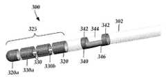
- FIG. 3illustrates one example of a distal portion of a lead 300 with a lead body 302 and electrodes 325 including one or more optional ring electrodes 320 , 320 a and multiple segmented electrodes 330 .
- the lead 300also includes a marker 340 that is asymmetrically shaped.
- the marker 340is made of a material that is substantially different from the material of the lead body 302 , particularly, when viewed using a radiological imaging technique, such as CT imaging, so that the marker is radiologically distinguishable from the lead body.
- the marker 340is made of metal (such as a pure metal or an alloy) and, in at least some embodiments, is made of the same material as the electrodes 325 .
- the marker 340defines one or more optional rings 342 formed around the entire perimeter of the lead 300 , at least one window 344 , and a longitudinal band 346 disposed opposite the window.
- the longitudinal band 346 of the marker 340extends around no more than 80%, 75%, 67%, 60%, 50%, 40%, 34%, 30%, 25%, or 20% of the perimeter of the lead with the window 344 extending around the remainder of the perimeter.
- the longitudinal band 346will extend around less than half the perimeter of the lead and may extend around no more than one third or one quarter of the perimeter.
- the longitudinal band 346 of the marker 340is aligned with at least one of the segmented electrodes 330 (such as segmented electrodes 330 a , 330 b in the illustrated embodiment of FIG. 3 .) In the illustrated embodiments, the longitudinal band 346 extends between two rings 342 .
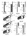
- FIGS. 4A-4Cillustrate another embodiment of a marker 440 with two rings 442 a , 442 b , a window 444 , a longitudinal band 446 opposite the window, and a longitudinal extension 448 extending from one of the rings 442 b .
- the arrangement and design considerations described above for rings 342 , window 344 , and longitudinal band 346are also applicable to rings 442 a , 442 b , window 444 , and longitudinal band 446 .
- the longitudinal extension 448extends from the proximal ring 442 b , but in other embodiments the longitudinal extension can extend from the distal ring 442 a .
- the markercan have two longitudinal extensions which each extend from a different one of the rings.
- the longitudinal extension 448 of the marker 440extends around no more than 80%, 75%, 67%, 60%, 50%, 40%, 34%, 30%, 25%, or 20% of the perimeter of the lead.
- the longitudinal extension 448will extend around less than half the perimeter of the lead and may extend around no more than one third or one quarter of the perimeter.
- the longitudinal extension 448 of the marker 440is aligned with at least one of the segmented electrodes (such as one of segmented electrodes 330 a , 330 b in the illustrated embodiment of FIG. 3 .)
- the circumferential width of the longitudinal extension 448is the same as the circumferential width of the longitudinal band 446 . In other embodiments, the circumferential width of the longitudinal extension 448 is larger (for example, by at least 10%, 20%, 25% or more of the longitudinal band) or smaller (for example, by at least 10%, 20%, 25% or more of the longitudinal band) than the circumferential width of the longitudinal band 446 . In addition, the longitudinal extension 448 and longitudinal band 446 can have a same or different shape.
- a longitudinal length of the longitudinal band 446is different from the longitudinal length of the longitudinal extension 448 .
- the longitudinal band 446is longer (optionally, by at least 10, 20, 30, 40, or 50% or more of the longitudinal band) than the longitudinal extension 448 .
- the longitudinal extensionis longer (optionally, by at least 10, 20, 30, 40, or 50% or more of the longitudinal band) than the longitudinal band.
- the longitudinal extension 448will be circumferentially offset from the longitudinal band 446 by at least 30, 45, 60, 90, 100, 120, 140, 160, or 180 degrees. In at least some embodiments, as illustrated in FIGS. 4A-4C , the longitudinal extension 448 and longitudinal band 446 are circumferentially offset so that they are positioned around non-overlapping portions of the perimeter of the lead (which may or may not share a starting/ending point). It has been found that the marker 340 of FIG. 3 requires either a CT scan or two perpendicular planar images (for example, planar x-ray or fluoroscopic images) to determine the orientation of the lead.
- a single planar image(for example, a single x-ray or fluoroscopic image), in a plane that includes or is parallel to the longitudinal axis of the lead, may be all that is needed for determining lead orientation.
- FIG. 4Dillustrates another embodiment of the marker 440 where the proximal ring 442 b is a partial ring with a slit 443 through the ring.
- any ring of the markers described hereincan be full rings or partial rings with one or more slits through the ring.
- the slit 443can extend through the entire longitudinal width of the ring, as illustrated in FIG. 4D , or only partway along the longitudinal width of the ring.
- other markerscan be formed with only a single ring (see, for example, FIGS. 5A-5F ) or no rings.
- FIGS. 5A-5Cillustrate a further embodiment of a marker 540 with a single ring 542 , a longitudinal band 546 extending distally from the ring 542 , and a longitudinal extension 548 extending proximally from the ring 542 .
- the arrangement and design considerations described above for rings 342 , 442 a , 442 b ; longitudinal bands 346 , 446 ; and longitudinal extension 448are also applicable to ring 542 , longitudinal band 546 , and longitudinal extension 548 .
- the longitudinal extension 548 and longitudinal band 546are circumferentially offset so that they are positioned around non-overlapping portions of the perimeter of the lead (which may or may not share a starting/ending point).
- the longitudinal band 546is longer than the longitudinal extension 548 , although in other embodiments they may have equal lengths or the longitudinal band may be shorter than the longitudinal extension. As indicated above, the arrangement, position, and lengths of the longitudinal band and longitudinal extension can be modified to provide other suitable embodiments.
- FIG. 5Dillustrates another embodiment of the marker 540 where the ring 542 is a partial ring with a slit 543 through the ring.
- FIG. 5Eillustrates yet another embodiment where the ring 542 has a slit 549 that only extends partway through the ring (and, in the illustrated embodiment, forms a notch in the ring).
- FIG. 5Fillustrates a further embodiment with one or more apertures 551 in the ring 542 , the longitudinal band 548 , or both. Alternatively or additionally, apertures 551 can be positioned in the longitudinal extension 548 .
- the apertures 551may facilitate maintaining attachment of the marker to the lead body, particularly, if a portion of the lead body extends into or through the aperture.
- the one or more aperturescan have any suitable shape including, but not limited to, round, square, rectangular, triangular, hexagonal, octagonal, or any other regular or irregular shape.
- FIGS. 6A-6Cillustrate yet another embodiment of a marker 640 with two rings 642 a , 642 b , a window 644 , and a longitudinal band 646 opposite the window.
- the arrangement and design considerations described above for rings 342 , window 344 , and longitudinal band 346are also applicable to rings 642 a , 642 b , window 644 , and longitudinal band 646 .
- the circumferential width of the longitudinal band 646varies along the longitudinal length of the longitudinal band. In the illustrated embodiment, this variation forms a notch 647 in the longitudinal band 646 . In at least some embodiments, including the illustrated embodiment of FIGS.
- the marker 640may facilitate the use of a single planar image single planar image (for example, a single x-ray or fluoroscopic image), in a plane that includes or is parallel to the longitudinal axis of the lead, for determining lead orientation.
- a single planar image single planar imagefor example, a single x-ray or fluoroscopic image
- FIG. 6Dillustrates another embodiment of the marker 640 where the rings 642 a , 642 b are both partial rings with a slit 643 through each ring. It will be recognized that in other embodiments, only one of the rings 642 a , 642 b includes a slit.
- the longitudinal band 646narrows from both ends to a narrowest portion in the center of the longitudinal band.
- the narrowest portionmay be at any other portion of the longitudinal band.
- the longitudinal bandmay widen towards to center or any other position along the longitudinal band.
- the longitudinal bandmay have any arrangement of narrower and wider portions or any other arrangement of one or more non-straight longitudinal edges.
- the longitudinal band 646may also be modified to include a longitudinal extension (such as longitudinal extensions 448 , 548 ) or modified to remove one of the rings 642 a , 642 b , or any combination of the modifications described in this paragraph.
- a longitudinal extensionsuch as longitudinal extensions 448 , 548
- any of the embodiments illustrated in FIGS. 4A-5Ccan be modified to include one or more non-straight longitudinal edges along the longitudinal band or longitudinal extension (or both).
- the markers described hereinare made of a radiopaque material such as metals or radiopaque plastics or composites.
- the markerscan be made by any suitable method including, but not limited to, machining, molding, casting or the like.
- the markerscan be coupled to a lead in any suitable manner including in the same or similar manner to the coupling of electrodes or terminals to a lead.
- Radiological imagingsuch as computed tomography (CT), x-ray, or fluoroscopic imaging, can be used to identify the orientation of the lead due to the asymmetry of the marker.
- CTcomputed tomography
- asymmetrical markersuch as marker 340 , 440 , 540 , 640
- imaging techniquessuch as CT imaging or other radiological imaging techniques. Examples of methods and systems for identifying lead orientation using radiological imaging and the markers described above are presented in U.S. Provisional Patent Application Ser. Nos. 62/209,001 and 62/212,775 and U.S. Provisional Patent Application Ser. No. 62/408,399, all of which are incorporated herein by reference in their entirety.
- a single planar image of a lead with marker 440 , 540 , 640can be used to determine lead orientation.
Landscapes
- Health & Medical Sciences (AREA)
- Life Sciences & Earth Sciences (AREA)
- Engineering & Computer Science (AREA)
- Public Health (AREA)
- Biomedical Technology (AREA)
- Nuclear Medicine, Radiotherapy & Molecular Imaging (AREA)
- Veterinary Medicine (AREA)
- Animal Behavior & Ethology (AREA)
- General Health & Medical Sciences (AREA)
- Radiology & Medical Imaging (AREA)
- Heart & Thoracic Surgery (AREA)
- Neurology (AREA)
- Neurosurgery (AREA)
- Cardiology (AREA)
- Surgery (AREA)
- Physical Education & Sports Medicine (AREA)
- Gastroenterology & Hepatology (AREA)
- Orthopedic Medicine & Surgery (AREA)
- Molecular Biology (AREA)
- Medical Informatics (AREA)
- Pathology (AREA)
- Oral & Maxillofacial Surgery (AREA)
- Electrotherapy Devices (AREA)
Abstract
Description
Claims (19)
Priority Applications (1)
| Application Number | Priority Date | Filing Date | Title |
|---|---|---|---|
| US15/729,424US10525257B2 (en) | 2016-10-14 | 2017-10-10 | Orientation marker for implantable leads and leads, systems, and methods utilizing the orientation marker |
Applications Claiming Priority (2)
| Application Number | Priority Date | Filing Date | Title |
|---|---|---|---|
| US201662408392P | 2016-10-14 | 2016-10-14 | |
| US15/729,424US10525257B2 (en) | 2016-10-14 | 2017-10-10 | Orientation marker for implantable leads and leads, systems, and methods utilizing the orientation marker |
Publications (2)
| Publication Number | Publication Date |
|---|---|
| US20180104472A1 US20180104472A1 (en) | 2018-04-19 |
| US10525257B2true US10525257B2 (en) | 2020-01-07 |
Family
ID=60186385
Family Applications (1)
| Application Number | Title | Priority Date | Filing Date |
|---|---|---|---|
| US15/729,424ActiveUS10525257B2 (en) | 2016-10-14 | 2017-10-10 | Orientation marker for implantable leads and leads, systems, and methods utilizing the orientation marker |
Country Status (2)
| Country | Link |
|---|---|
| US (1) | US10525257B2 (en) |
| WO (1) | WO2018071420A1 (en) |
Cited By (9)
| Publication number | Priority date | Publication date | Assignee | Title |
|---|---|---|---|---|
| US11690683B2 (en) | 2021-07-01 | 2023-07-04 | Remedy Robotics, Inc | Vision-based position and orientation determination for endovascular tools |
| US11707332B2 (en) | 2021-07-01 | 2023-07-25 | Remedy Robotics, Inc. | Image space control for endovascular tools |
| US11779406B2 (en) | 2020-06-19 | 2023-10-10 | Remedy Robotics, Inc. | Systems and methods for guidance of intraluminal devices within the vasculature |
| WO2024197009A1 (en) | 2023-03-22 | 2024-09-26 | Boston Scientific Neuromodulation Corporation | Systems for moving stimulation using anatomical directional controls |
| US12121307B2 (en) | 2021-07-01 | 2024-10-22 | Remedy Robotics, Inc. | Vision-based position and orientation determination for endovascular tools |
| US12121379B2 (en) | 2020-08-31 | 2024-10-22 | Medtronic, Inc. | Lead orientation detection |
| US12208268B2 (en) | 2014-10-07 | 2025-01-28 | Boston Scientific Neuromodulation Corporation | Systems, devices, and methods for electrical stimulation using feedback to adjust stimulation parameters |
| US12403313B2 (en) | 2021-06-15 | 2025-09-02 | Boston Scientific Neuromodulation Corporation | Methods and systems for estimating neural activation by stimulation using a stimulation system |
| US12403315B2 (en) | 2021-04-27 | 2025-09-02 | Boston Scientific Neuromodulation Corporation | Systems and methods for automated programming of electrical stimulation |
Families Citing this family (8)
| Publication number | Priority date | Publication date | Assignee | Title |
|---|---|---|---|---|
| US10631937B2 (en) | 2017-04-14 | 2020-04-28 | Boston Scientific Neuromodulation Corporation | Systems and methods for determining orientation of an implanted electrical stimulation lead |
| WO2019210114A2 (en) | 2018-04-27 | 2019-10-31 | Boston Scientific Neuromodulation Corporation | Translation between cathodic and anodic neuromodulation parameter settings |
| US10959672B2 (en)* | 2019-04-25 | 2021-03-30 | Medtronic, Inc. | Identification of orientation of implanted lead |
| US11627913B2 (en)* | 2019-04-25 | 2023-04-18 | Medtronic, Inc. | Identification of orientation of implanted lead |
| WO2021067486A1 (en)* | 2019-09-30 | 2021-04-08 | The Board Of Trustees Of The Leland Stanford Junior University | Neurostimulators to improve male orgasm and systems and methods for use |
| US11806532B2 (en)* | 2019-11-26 | 2023-11-07 | Heraeus Medical Components Llc | Implantable lead with asymmetric fiducial marker |
| EP4281159A1 (en)* | 2021-01-20 | 2023-11-29 | Medtronic, Inc. | Lead construction including alignable marker elements |
| PL446842A1 (en)* | 2023-11-25 | 2025-05-26 | Marcin ROJEK | Radiological marker for spatial analysis of medical instrument placement in the patient's body |
Citations (80)
| Publication number | Priority date | Publication date | Assignee | Title |
|---|---|---|---|---|
| US6181969B1 (en) | 1998-06-26 | 2001-01-30 | Advanced Bionics Corporation | Programmable current output stimulus stage for implantable device |
| US6516227B1 (en) | 1999-07-27 | 2003-02-04 | Advanced Bionics Corporation | Rechargeable spinal cord stimulator system |
| US6609029B1 (en) | 2000-02-04 | 2003-08-19 | Advanced Bionics Corporation | Clip lock mechanism for retaining lead |
| US6609032B1 (en) | 1999-01-07 | 2003-08-19 | Advanced Bionics Corporation | Fitting process for a neural stimulation system |
| US6741892B1 (en) | 2000-03-10 | 2004-05-25 | Advanced Bionics Corporation | Movable contact locking mechanism for spinal cord stimulator lead connector |
| US20070150036A1 (en) | 2005-12-27 | 2007-06-28 | Advanced Bionics Corporation | Stimulator leads and methods for lead fabrication |
| US7244150B1 (en) | 2006-01-09 | 2007-07-17 | Advanced Bionics Corporation | Connector and methods of fabrication |
| US7437193B2 (en) | 2002-06-28 | 2008-10-14 | Boston Scientific Neuromodulation Corporation | Microstimulator employing improved recharging reporting and telemetry techniques |
| US7450997B1 (en) | 2000-12-29 | 2008-11-11 | Boston Scientific Neuromodulation Corporation | Method of implanting a lead for brain stimulation |
| US20090187222A1 (en) | 2008-01-23 | 2009-07-23 | Boston Scientific Neuromodulation Corporation | Steerable stylet handle assembly |
| US20090204192A1 (en)* | 2008-02-11 | 2009-08-13 | Intelect Medical, Inc. | Directional electrode devices with locating features |
| US20090276021A1 (en) | 2008-04-30 | 2009-11-05 | Boston Scientific Neuromodulation Corporation | Electrodes for stimulation leads and methods of manufacture and use |
| US20090287271A1 (en) | 2008-05-15 | 2009-11-19 | Intelect Medical, Inc. | Clinician programmer system and method for calculating volumes of activation |
| US7650184B2 (en) | 2005-12-01 | 2010-01-19 | Boston Scientific Neuromodulation Corporation | Cylindrical multi-contact electrode lead for neural stimulation and method of making same |
| US20100030298A1 (en) | 2006-09-26 | 2010-02-04 | Koninklijke Philips Electronics N.V. | Tissue stimulation method and apparatus |
| US7672734B2 (en) | 2005-12-27 | 2010-03-02 | Boston Scientific Neuromodulation Corporation | Non-linear electrode array |
| US20100076535A1 (en) | 2008-09-25 | 2010-03-25 | Boston Scientific Neuromodulation Corporation | Leads with non-circular-shaped distal ends for brain stimulation systems and methods of making and using |
| US7761165B1 (en) | 2005-09-29 | 2010-07-20 | Boston Scientific Neuromodulation Corporation | Implantable stimulator with integrated plastic housing/metal contacts and manufacture and use |
| US7783359B2 (en) | 2005-01-05 | 2010-08-24 | Boston Scientific Neuromodulation Corporation | Devices and methods using an implantable pulse generator for brain stimulation |
| US7809446B2 (en) | 2005-01-05 | 2010-10-05 | Boston Scientific Neuromodulation Corporation | Devices and methods for brain stimulation |
| US20100268298A1 (en) | 2009-04-16 | 2010-10-21 | Boston Scientific Neuromodulation Corporation | Deep brain stimulation current steering with split electrodes |
| US20110005069A1 (en) | 2009-07-07 | 2011-01-13 | Boston Scientific Neuromodulation Corporation | Systems and leads with a radially segmented electrode array and methods of manufacture |
| US20110078900A1 (en) | 2009-07-07 | 2011-04-07 | Boston Scientific Neuromodulation Corporation | Methods for making leads with radially-aligned segmented electrodes for electrical stimulation systems |
| US7949395B2 (en) | 1999-10-01 | 2011-05-24 | Boston Scientific Neuromodulation Corporation | Implantable microdevice with extended lead and remote electrode |
| US20110130816A1 (en) | 2009-11-30 | 2011-06-02 | Boston Scientific Neuromodulation Corporation | Electrode array with electrodes having cutout portions and methods of making the same |
| US20110130817A1 (en) | 2009-11-30 | 2011-06-02 | Boston Scientific Neuromodulation Corporation | Electrode array having a rail system and methods of manufacturing the same |
| US20110130818A1 (en) | 2009-11-30 | 2011-06-02 | Boston Scientific Neuromodulation Corporation | Electrode array having concentric split ring electrodes and methods of making the same |
| US20110130803A1 (en) | 2009-11-30 | 2011-06-02 | Boston Scientific Neuromodulation Corporation | Electrode array having concentric windowed cylinder electrodes and methods of making the same |
| US7974706B2 (en) | 2006-03-30 | 2011-07-05 | Boston Scientific Neuromodulation Corporation | Electrode contact configurations for cuff leads |
| US8019439B2 (en) | 2005-01-11 | 2011-09-13 | Boston Scientific Neuromodulation Corporation | Lead assembly and method of making same |
| US20110238129A1 (en) | 2010-03-23 | 2011-09-29 | Boston Scientific Neuromodulation Corporation | Helical radial spacing of contacts on a cylindrical lead |
| US20110257707A1 (en) | 2010-04-19 | 2011-10-20 | Boston Scientific Neuromodulation Corporation | Neurostimulation system and method with adjustable programming rate |
| US20110313500A1 (en) | 2010-06-18 | 2011-12-22 | Boston Scientific Neuromodulation Corporation | Electrode array having embedded electrodes and methods of making the same |
| US20120016378A1 (en) | 2010-07-16 | 2012-01-19 | Boston Scientific Neuromodulation Corporation | Systems and methods for radial steering of electrode arrays |
| US20120046715A1 (en) | 2010-08-18 | 2012-02-23 | Boston Scientific Neuromodulation Corporation | User interface for segmented neurostimulation leads |
| US20120046710A1 (en) | 2010-08-18 | 2012-02-23 | Boston Scientific Neuromodulation Corporation | Methods, systems, and devices for deep brain stimulation using helical movement of the centroid of stimulation |
| US20120071949A1 (en) | 2010-09-21 | 2012-03-22 | Boston Scientific Neuromodulation Corporation | Systems and methods for making and using radially-aligned segmented electrodes for leads of electrical stimulation systems |
| US8175710B2 (en) | 2006-03-14 | 2012-05-08 | Boston Scientific Neuromodulation Corporation | Stimulator system with electrode array and the method of making the same |
| US20120165911A1 (en) | 2010-12-23 | 2012-06-28 | Boston Scientific Neuromodulation Corporation | Methods for making leads with segmented electrodes for electrical stimulation systems |
| US8224450B2 (en) | 2006-09-18 | 2012-07-17 | Boston Scientific Neuromodulation Corporation | Feed through interconnect assembly for an implantable stimulation system and methods of making and using |
| US20120197375A1 (en) | 2011-02-02 | 2012-08-02 | Boston Scientific Neuromodulation Corporation | Leads with spiral of helical segmented electrode arrays and methods of making and using the leads |
| US20120203316A1 (en) | 2011-02-08 | 2012-08-09 | Boston Scientific Neuromodulation Corporation | Leads with segmented electrodes for electrical stimulation of planar regions and methods of making and using |
| US20120203321A1 (en) | 2011-02-08 | 2012-08-09 | Boston Scientific Neuromodulation Corporation | Methods for making leads with segmented electrodes for electrical stimulation systems |
| US20120203320A1 (en) | 2011-02-08 | 2012-08-09 | Boston Scientific Neuromodulation Corporation | Leads with spirally arranged segmented electrodes and methods of making and using the leads |
| US8271094B1 (en) | 2005-09-30 | 2012-09-18 | Boston Scientific Neuromodulation Corporation | Devices with cannula and electrode lead for brain stimulation and methods of use and manufacture |
| US20120314919A1 (en) | 2011-03-29 | 2012-12-13 | Boston Scientific Neuromodulation Corporation | System and method for leadwire location |
| US20120316615A1 (en) | 2011-06-07 | 2012-12-13 | Boston Scientific Neuromodulation Corporation | Systems and methods for making and using improved leads for electrical stimulation systems |
| US8364278B2 (en) | 2002-01-29 | 2013-01-29 | Boston Scientific Neuromodulation Corporation | Lead assembly for implantable microstimulator |
| US20130039550A1 (en) | 2011-08-09 | 2013-02-14 | Boston Scientific Neuromodulation Corporation | System and method for weighted atlas generation |
| US20130105071A1 (en) | 2011-11-02 | 2013-05-02 | Boston Scientific Neuromodulation Corporation | Systems and methods for making and using improved leads for electrical stimulation systems |
| US20130116744A1 (en) | 2011-08-09 | 2013-05-09 | Boston Scientific Neuromodulation Corporation | VOA generation system and method using a fiber specific analysis |
| US20130197602A1 (en) | 2012-01-26 | 2013-08-01 | Boston Scientific Neuromodulation Corporation | Systems and methods for identifying the circumferential positioning of electrodes of leads for electrical stimulation systems |
| US20130197424A1 (en) | 2006-07-31 | 2013-08-01 | Cranial Medical Systems, Inc. | Lead and methods for brain monitoring and modulation |
| US20130267837A1 (en) | 2012-04-10 | 2013-10-10 | NeuroAccess Technologies | Electrical lead positioning systems and methods |
| US20140039587A1 (en) | 2012-08-03 | 2014-02-06 | Boston Scientific Neuromodulation Corporation | Leads with electrode carrier for segmented electrodes and methods of making and using |
| US8688235B1 (en) | 2008-07-22 | 2014-04-01 | Boston Scientific Neuromodulation Corporation | Lead with transition and methods of manufacture and use |
| US20140122379A1 (en) | 2012-11-01 | 2014-05-01 | Boston Scientific Neuromodulation Corporation | Systems and methods for voa model generation and use |
| US8792993B2 (en) | 2012-06-01 | 2014-07-29 | Boston Scientific, Neuromodulation Corporation | Leads with tip electrode for electrical stimulation systems and methods of making and using |
| US20140228921A1 (en) | 2012-03-30 | 2014-08-14 | Boston Scientific Neuromodulation Corporation | Leads with x-ray fluorescent capsules for electrode identification and methods of manufacture and use |
| US20140257444A1 (en)* | 2013-03-08 | 2014-09-11 | Medtronic, Inc. | Radiopaque markers for implantable medical leads |
| US20140257428A1 (en) | 2013-03-08 | 2014-09-11 | Boston Scientific Neuromodulation Corporation | Neuromodulation using modulated pulse train |
| US20140276002A1 (en) | 2013-03-15 | 2014-09-18 | The Cleveland Clinic Foundation | Method and system to facilitate intraoperative positioning and guidance |
| US20140358208A1 (en) | 2013-05-31 | 2014-12-04 | Boston Scientific Neuromodulation Corporation | Segmented electrode leads formed from pre-electrodes with alignment features and methods of making and using the leads |
| US20140358210A1 (en) | 2013-05-31 | 2014-12-04 | Boston Scientific Neuromodulation Corporation | Methods for manufacturing segmented electrode leads using a removable ring and the leads formed thereby |
| US20140353001A1 (en) | 2013-05-31 | 2014-12-04 | Boston Scientific Neuromodulation Corporation | Leads containing segmented electrodes with non-perpendicular legs and methods of making and using |
| US20140358207A1 (en) | 2013-05-31 | 2014-12-04 | Boston Scientific Neuromodulation Corporation | Segmented electrode leads formed from pre-electrodes with depressions or apertures and methods of making and using |
| US20140358209A1 (en) | 2013-05-31 | 2014-12-04 | Boston Scientific Neuromodulation Corporation | Leads with segmented electrodes and methods of making and using the leads |
| US20140371819A1 (en) | 2008-01-31 | 2014-12-18 | Medtronic, Inc. | Automated programming of electrical stimulation electrodes using post-implant imaging |
| US20150018915A1 (en) | 2013-07-12 | 2015-01-15 | Boston Scientific Neuromodulation Corporation | Leads with segmented electrodes and methods of making and using the leads |
| US20150045864A1 (en) | 2013-08-07 | 2015-02-12 | Boston Scientific Neuromodulation Corporation | Systems and methods for making and using segmented tip electrodes for leads of electrical stimulation systems |
| US20150051681A1 (en) | 2013-08-19 | 2015-02-19 | Boston Scientific Neuromodulation Corporation | Methods and systems for anodal stimulation to affect cranial and other nerves |
| US20150066120A1 (en) | 2013-08-30 | 2015-03-05 | Boston Scientific Neuromodulation Corporation | Methods of making segmented electrode leads using flanged carrier |
| US20150066111A1 (en) | 2010-06-14 | 2015-03-05 | Boston Scientific Neuromodulation Corporation | Programming interface for spinal cord neuromodulation |
| US9037256B2 (en) | 2011-09-01 | 2015-05-19 | Boston Scientific Neuromodulation Corporation | Methods and system for targeted brain stimulation using electrical parameter maps |
| US20150151113A1 (en) | 2013-12-02 | 2015-06-04 | Boston Scientific Neuromodulation Corporation | Electrical stimulation leads with helically arranged electrodes and methods of making and using |
| US20150157851A1 (en) | 2013-12-05 | 2015-06-11 | Advanced Neuromodulation Systems, Inc. | Medical leads with segmented electrodes and methods of fabrication thereof |
| US20160030749A1 (en) | 2014-07-30 | 2016-02-04 | Boston Scientific Neuromodulation Corporation | Systems and methods for stimulation-related patient population volume analysis and use |
| US20160228692A1 (en) | 2015-02-06 | 2016-08-11 | Boston Scientific Neuromodulation Corporation | Systems and methods for making and using improved contact arrays for electrical stimulation systems |
| US20170056678A1 (en) | 2015-09-01 | 2017-03-02 | Boston Scientific Neuromodulation Corporation | Detection of lead orientation |
| US20170061627A1 (en) | 2015-08-24 | 2017-03-02 | Boston Scientific Neuromodulation Corporation | Systems and methods for determining orientation of an implanted lead |
- 2017
- 2017-10-10USUS15/729,424patent/US10525257B2/enactiveActive
- 2017-10-10WOPCT/US2017/055943patent/WO2018071420A1/ennot_activeCeased
Patent Citations (95)
| Publication number | Priority date | Publication date | Assignee | Title |
|---|---|---|---|---|
| US6181969B1 (en) | 1998-06-26 | 2001-01-30 | Advanced Bionics Corporation | Programmable current output stimulus stage for implantable device |
| US6609032B1 (en) | 1999-01-07 | 2003-08-19 | Advanced Bionics Corporation | Fitting process for a neural stimulation system |
| US6516227B1 (en) | 1999-07-27 | 2003-02-04 | Advanced Bionics Corporation | Rechargeable spinal cord stimulator system |
| US6895280B2 (en) | 1999-07-27 | 2005-05-17 | Advanced Bionics Corporation | Rechargeable spinal cord stimulator system |
| US7949395B2 (en) | 1999-10-01 | 2011-05-24 | Boston Scientific Neuromodulation Corporation | Implantable microdevice with extended lead and remote electrode |
| US6609029B1 (en) | 2000-02-04 | 2003-08-19 | Advanced Bionics Corporation | Clip lock mechanism for retaining lead |
| US6741892B1 (en) | 2000-03-10 | 2004-05-25 | Advanced Bionics Corporation | Movable contact locking mechanism for spinal cord stimulator lead connector |
| US7450997B1 (en) | 2000-12-29 | 2008-11-11 | Boston Scientific Neuromodulation Corporation | Method of implanting a lead for brain stimulation |
| US7792590B1 (en) | 2000-12-29 | 2010-09-07 | Boston Scientific Neuromodulation Corporation | Implantable lead systems for brain stimulation |
| US8364278B2 (en) | 2002-01-29 | 2013-01-29 | Boston Scientific Neuromodulation Corporation | Lead assembly for implantable microstimulator |
| US7437193B2 (en) | 2002-06-28 | 2008-10-14 | Boston Scientific Neuromodulation Corporation | Microstimulator employing improved recharging reporting and telemetry techniques |
| US20110004267A1 (en) | 2005-01-05 | 2011-01-06 | Boston Scientific Neuromodulation Corporation | Devices and methods for brain stimulation |
| US7809446B2 (en) | 2005-01-05 | 2010-10-05 | Boston Scientific Neuromodulation Corporation | Devices and methods for brain stimulation |
| US7783359B2 (en) | 2005-01-05 | 2010-08-24 | Boston Scientific Neuromodulation Corporation | Devices and methods using an implantable pulse generator for brain stimulation |
| US8019439B2 (en) | 2005-01-11 | 2011-09-13 | Boston Scientific Neuromodulation Corporation | Lead assembly and method of making same |
| US7761165B1 (en) | 2005-09-29 | 2010-07-20 | Boston Scientific Neuromodulation Corporation | Implantable stimulator with integrated plastic housing/metal contacts and manufacture and use |
| US8271094B1 (en) | 2005-09-30 | 2012-09-18 | Boston Scientific Neuromodulation Corporation | Devices with cannula and electrode lead for brain stimulation and methods of use and manufacture |
| US7650184B2 (en) | 2005-12-01 | 2010-01-19 | Boston Scientific Neuromodulation Corporation | Cylindrical multi-contact electrode lead for neural stimulation and method of making same |
| US20070150036A1 (en) | 2005-12-27 | 2007-06-28 | Advanced Bionics Corporation | Stimulator leads and methods for lead fabrication |
| US7672734B2 (en) | 2005-12-27 | 2010-03-02 | Boston Scientific Neuromodulation Corporation | Non-linear electrode array |
| US7244150B1 (en) | 2006-01-09 | 2007-07-17 | Advanced Bionics Corporation | Connector and methods of fabrication |
| US8175710B2 (en) | 2006-03-14 | 2012-05-08 | Boston Scientific Neuromodulation Corporation | Stimulator system with electrode array and the method of making the same |
| US7974706B2 (en) | 2006-03-30 | 2011-07-05 | Boston Scientific Neuromodulation Corporation | Electrode contact configurations for cuff leads |
| US20130197424A1 (en) | 2006-07-31 | 2013-08-01 | Cranial Medical Systems, Inc. | Lead and methods for brain monitoring and modulation |
| US8224450B2 (en) | 2006-09-18 | 2012-07-17 | Boston Scientific Neuromodulation Corporation | Feed through interconnect assembly for an implantable stimulation system and methods of making and using |
| US20100030298A1 (en) | 2006-09-26 | 2010-02-04 | Koninklijke Philips Electronics N.V. | Tissue stimulation method and apparatus |
| US20090187222A1 (en) | 2008-01-23 | 2009-07-23 | Boston Scientific Neuromodulation Corporation | Steerable stylet handle assembly |
| US20140371819A1 (en) | 2008-01-31 | 2014-12-18 | Medtronic, Inc. | Automated programming of electrical stimulation electrodes using post-implant imaging |
| US20090204192A1 (en)* | 2008-02-11 | 2009-08-13 | Intelect Medical, Inc. | Directional electrode devices with locating features |
| US20090276021A1 (en) | 2008-04-30 | 2009-11-05 | Boston Scientific Neuromodulation Corporation | Electrodes for stimulation leads and methods of manufacture and use |
| US20090287271A1 (en) | 2008-05-15 | 2009-11-19 | Intelect Medical, Inc. | Clinician programmer system and method for calculating volumes of activation |
| US8831731B2 (en) | 2008-05-15 | 2014-09-09 | Intelect Medical, Inc. | Clinician programmer system and method for calculating volumes of activation |
| US8849632B2 (en) | 2008-05-15 | 2014-09-30 | Intelect Medical, Inc. | Clinician programmer system and method for generating interface models and displays of volumes of activation |
| US20090287273A1 (en) | 2008-05-15 | 2009-11-19 | Intelect Medical, Inc. | Clinician programmer system interface for monitoring patient progress |
| US20090287272A1 (en) | 2008-05-15 | 2009-11-19 | Intelect Medical, Inc. | Clinician programmer system and method for steering volumesof activation |
| US8326433B2 (en) | 2008-05-15 | 2012-12-04 | Intelect Medical, Inc. | Clinician programmer system and method for calculating volumes of activation for monopolar and bipolar electrode configurations |
| US8688235B1 (en) | 2008-07-22 | 2014-04-01 | Boston Scientific Neuromodulation Corporation | Lead with transition and methods of manufacture and use |
| US20100076535A1 (en) | 2008-09-25 | 2010-03-25 | Boston Scientific Neuromodulation Corporation | Leads with non-circular-shaped distal ends for brain stimulation systems and methods of making and using |
| US8473061B2 (en) | 2009-04-16 | 2013-06-25 | Boston Scientific Neuromodulation Corporation | Deep brain stimulation current steering with split electrodes |
| US20100268298A1 (en) | 2009-04-16 | 2010-10-21 | Boston Scientific Neuromodulation Corporation | Deep brain stimulation current steering with split electrodes |
| US20110078900A1 (en) | 2009-07-07 | 2011-04-07 | Boston Scientific Neuromodulation Corporation | Methods for making leads with radially-aligned segmented electrodes for electrical stimulation systems |
| US20110005069A1 (en) | 2009-07-07 | 2011-01-13 | Boston Scientific Neuromodulation Corporation | Systems and leads with a radially segmented electrode array and methods of manufacture |
| US8295944B2 (en) | 2009-11-30 | 2012-10-23 | Boston Scientific Neuromodulation Corporation | Electrode array with electrodes having cutout portions and methods of making the same |
| US8391985B2 (en) | 2009-11-30 | 2013-03-05 | Boston Scientific Neuromodulation Corporation | Electrode array having concentric windowed cylinder electrodes and methods of making the same |
| US20110130816A1 (en) | 2009-11-30 | 2011-06-02 | Boston Scientific Neuromodulation Corporation | Electrode array with electrodes having cutout portions and methods of making the same |
| US20110130817A1 (en) | 2009-11-30 | 2011-06-02 | Boston Scientific Neuromodulation Corporation | Electrode array having a rail system and methods of manufacturing the same |
| US20110130818A1 (en) | 2009-11-30 | 2011-06-02 | Boston Scientific Neuromodulation Corporation | Electrode array having concentric split ring electrodes and methods of making the same |
| US20110130803A1 (en) | 2009-11-30 | 2011-06-02 | Boston Scientific Neuromodulation Corporation | Electrode array having concentric windowed cylinder electrodes and methods of making the same |
| US8571665B2 (en) | 2010-03-23 | 2013-10-29 | Boston Scientific Neuromodulation Corporation | Helical radial spacing of contacts on a cylindrical lead |
| US20110238129A1 (en) | 2010-03-23 | 2011-09-29 | Boston Scientific Neuromodulation Corporation | Helical radial spacing of contacts on a cylindrical lead |
| US20110257707A1 (en) | 2010-04-19 | 2011-10-20 | Boston Scientific Neuromodulation Corporation | Neurostimulation system and method with adjustable programming rate |
| US20150066111A1 (en) | 2010-06-14 | 2015-03-05 | Boston Scientific Neuromodulation Corporation | Programming interface for spinal cord neuromodulation |
| US20110313500A1 (en) | 2010-06-18 | 2011-12-22 | Boston Scientific Neuromodulation Corporation | Electrode array having embedded electrodes and methods of making the same |
| US20120016378A1 (en) | 2010-07-16 | 2012-01-19 | Boston Scientific Neuromodulation Corporation | Systems and methods for radial steering of electrode arrays |
| US20120046715A1 (en) | 2010-08-18 | 2012-02-23 | Boston Scientific Neuromodulation Corporation | User interface for segmented neurostimulation leads |
| US20120046710A1 (en) | 2010-08-18 | 2012-02-23 | Boston Scientific Neuromodulation Corporation | Methods, systems, and devices for deep brain stimulation using helical movement of the centroid of stimulation |
| US20120071949A1 (en) | 2010-09-21 | 2012-03-22 | Boston Scientific Neuromodulation Corporation | Systems and methods for making and using radially-aligned segmented electrodes for leads of electrical stimulation systems |
| US20120165911A1 (en) | 2010-12-23 | 2012-06-28 | Boston Scientific Neuromodulation Corporation | Methods for making leads with segmented electrodes for electrical stimulation systems |
| US20120197375A1 (en) | 2011-02-02 | 2012-08-02 | Boston Scientific Neuromodulation Corporation | Leads with spiral of helical segmented electrode arrays and methods of making and using the leads |
| US20120203316A1 (en) | 2011-02-08 | 2012-08-09 | Boston Scientific Neuromodulation Corporation | Leads with segmented electrodes for electrical stimulation of planar regions and methods of making and using |
| US20120203321A1 (en) | 2011-02-08 | 2012-08-09 | Boston Scientific Neuromodulation Corporation | Methods for making leads with segmented electrodes for electrical stimulation systems |
| US20120203320A1 (en) | 2011-02-08 | 2012-08-09 | Boston Scientific Neuromodulation Corporation | Leads with spirally arranged segmented electrodes and methods of making and using the leads |
| US8675945B2 (en) | 2011-03-29 | 2014-03-18 | Boston Scientific Neuromodulation Corporation | System and method for image registration |
| US20120314919A1 (en) | 2011-03-29 | 2012-12-13 | Boston Scientific Neuromodulation Corporation | System and method for leadwire location |
| US20120314924A1 (en) | 2011-03-29 | 2012-12-13 | Boston Scientific Neuromodulation Corporation | System and method for atlas registration |
| US20120316615A1 (en) | 2011-06-07 | 2012-12-13 | Boston Scientific Neuromodulation Corporation | Systems and methods for making and using improved leads for electrical stimulation systems |
| US20130116744A1 (en) | 2011-08-09 | 2013-05-09 | Boston Scientific Neuromodulation Corporation | VOA generation system and method using a fiber specific analysis |
| US20130039550A1 (en) | 2011-08-09 | 2013-02-14 | Boston Scientific Neuromodulation Corporation | System and method for weighted atlas generation |
| US8958615B2 (en) | 2011-08-09 | 2015-02-17 | Boston Scientific Neuromodulation Corporation | System and method for weighted atlas generation |
| US9037256B2 (en) | 2011-09-01 | 2015-05-19 | Boston Scientific Neuromodulation Corporation | Methods and system for targeted brain stimulation using electrical parameter maps |
| US20130105071A1 (en) | 2011-11-02 | 2013-05-02 | Boston Scientific Neuromodulation Corporation | Systems and methods for making and using improved leads for electrical stimulation systems |
| US20130197602A1 (en) | 2012-01-26 | 2013-08-01 | Boston Scientific Neuromodulation Corporation | Systems and methods for identifying the circumferential positioning of electrodes of leads for electrical stimulation systems |
| US20140228921A1 (en) | 2012-03-30 | 2014-08-14 | Boston Scientific Neuromodulation Corporation | Leads with x-ray fluorescent capsules for electrode identification and methods of manufacture and use |
| US20130267837A1 (en) | 2012-04-10 | 2013-10-10 | NeuroAccess Technologies | Electrical lead positioning systems and methods |
| US8792993B2 (en) | 2012-06-01 | 2014-07-29 | Boston Scientific, Neuromodulation Corporation | Leads with tip electrode for electrical stimulation systems and methods of making and using |
| US20140039587A1 (en) | 2012-08-03 | 2014-02-06 | Boston Scientific Neuromodulation Corporation | Leads with electrode carrier for segmented electrodes and methods of making and using |
| US20140122379A1 (en) | 2012-11-01 | 2014-05-01 | Boston Scientific Neuromodulation Corporation | Systems and methods for voa model generation and use |
| US20140257428A1 (en) | 2013-03-08 | 2014-09-11 | Boston Scientific Neuromodulation Corporation | Neuromodulation using modulated pulse train |
| US20140257444A1 (en)* | 2013-03-08 | 2014-09-11 | Medtronic, Inc. | Radiopaque markers for implantable medical leads |
| US20140276002A1 (en) | 2013-03-15 | 2014-09-18 | The Cleveland Clinic Foundation | Method and system to facilitate intraoperative positioning and guidance |
| US20140353001A1 (en) | 2013-05-31 | 2014-12-04 | Boston Scientific Neuromodulation Corporation | Leads containing segmented electrodes with non-perpendicular legs and methods of making and using |
| US20140358207A1 (en) | 2013-05-31 | 2014-12-04 | Boston Scientific Neuromodulation Corporation | Segmented electrode leads formed from pre-electrodes with depressions or apertures and methods of making and using |
| US20140358209A1 (en) | 2013-05-31 | 2014-12-04 | Boston Scientific Neuromodulation Corporation | Leads with segmented electrodes and methods of making and using the leads |
| US20140358208A1 (en) | 2013-05-31 | 2014-12-04 | Boston Scientific Neuromodulation Corporation | Segmented electrode leads formed from pre-electrodes with alignment features and methods of making and using the leads |
| US20140358210A1 (en) | 2013-05-31 | 2014-12-04 | Boston Scientific Neuromodulation Corporation | Methods for manufacturing segmented electrode leads using a removable ring and the leads formed thereby |
| US20150018915A1 (en) | 2013-07-12 | 2015-01-15 | Boston Scientific Neuromodulation Corporation | Leads with segmented electrodes and methods of making and using the leads |
| US20150045864A1 (en) | 2013-08-07 | 2015-02-12 | Boston Scientific Neuromodulation Corporation | Systems and methods for making and using segmented tip electrodes for leads of electrical stimulation systems |
| US20150051681A1 (en) | 2013-08-19 | 2015-02-19 | Boston Scientific Neuromodulation Corporation | Methods and systems for anodal stimulation to affect cranial and other nerves |
| US20150066120A1 (en) | 2013-08-30 | 2015-03-05 | Boston Scientific Neuromodulation Corporation | Methods of making segmented electrode leads using flanged carrier |
| US20150151113A1 (en) | 2013-12-02 | 2015-06-04 | Boston Scientific Neuromodulation Corporation | Electrical stimulation leads with helically arranged electrodes and methods of making and using |
| US20150157851A1 (en) | 2013-12-05 | 2015-06-11 | Advanced Neuromodulation Systems, Inc. | Medical leads with segmented electrodes and methods of fabrication thereof |
| US20160030749A1 (en) | 2014-07-30 | 2016-02-04 | Boston Scientific Neuromodulation Corporation | Systems and methods for stimulation-related patient population volume analysis and use |
| US20160228692A1 (en) | 2015-02-06 | 2016-08-11 | Boston Scientific Neuromodulation Corporation | Systems and methods for making and using improved contact arrays for electrical stimulation systems |
| US20170061627A1 (en) | 2015-08-24 | 2017-03-02 | Boston Scientific Neuromodulation Corporation | Systems and methods for determining orientation of an implanted lead |
| US20170056678A1 (en) | 2015-09-01 | 2017-03-02 | Boston Scientific Neuromodulation Corporation | Detection of lead orientation |
Non-Patent Citations (2)
| Title |
|---|
| International Search Report and Written Opinion for PCT Application No. PCT/US2017/055943 dated Jan. 2. 2018. |
| U.S. Appl. No. 15/783,807, filed Oct. 13, 2017. |
Cited By (10)
| Publication number | Priority date | Publication date | Assignee | Title |
|---|---|---|---|---|
| US12208268B2 (en) | 2014-10-07 | 2025-01-28 | Boston Scientific Neuromodulation Corporation | Systems, devices, and methods for electrical stimulation using feedback to adjust stimulation parameters |
| US11779406B2 (en) | 2020-06-19 | 2023-10-10 | Remedy Robotics, Inc. | Systems and methods for guidance of intraluminal devices within the vasculature |
| US12193764B2 (en) | 2020-06-19 | 2025-01-14 | Remedy Robotics, Inc. | Systems and methods for guidance of intraluminal devices within the vasculature |
| US12121379B2 (en) | 2020-08-31 | 2024-10-22 | Medtronic, Inc. | Lead orientation detection |
| US12403315B2 (en) | 2021-04-27 | 2025-09-02 | Boston Scientific Neuromodulation Corporation | Systems and methods for automated programming of electrical stimulation |
| US12403313B2 (en) | 2021-06-15 | 2025-09-02 | Boston Scientific Neuromodulation Corporation | Methods and systems for estimating neural activation by stimulation using a stimulation system |
| US11690683B2 (en) | 2021-07-01 | 2023-07-04 | Remedy Robotics, Inc | Vision-based position and orientation determination for endovascular tools |
| US11707332B2 (en) | 2021-07-01 | 2023-07-25 | Remedy Robotics, Inc. | Image space control for endovascular tools |
| US12121307B2 (en) | 2021-07-01 | 2024-10-22 | Remedy Robotics, Inc. | Vision-based position and orientation determination for endovascular tools |
| WO2024197009A1 (en) | 2023-03-22 | 2024-09-26 | Boston Scientific Neuromodulation Corporation | Systems for moving stimulation using anatomical directional controls |
Also Published As
| Publication number | Publication date |
|---|---|
| US20180104472A1 (en) | 2018-04-19 |
| WO2018071420A1 (en) | 2018-04-19 |
Similar Documents
| Publication | Publication Date | Title |
|---|---|---|
| US10525257B2 (en) | Orientation marker for implantable leads and leads, systems, and methods utilizing the orientation marker | |
| US7668601B2 (en) | Implantable medical lead with multiple electrode configurations | |
| US8996132B2 (en) | Leads with tip electrode for electrical stimulation systems and methods of making and using | |
| US8744596B2 (en) | Leads with X-ray fluorescent capsules for electrode identification and methods of manufacture and use | |
| US9427567B2 (en) | Leads with electrode carrier for segmented electrodes and methods of making and using | |
| US10286205B2 (en) | Systems and methods for making and using improved contact arrays for electrical stimulation systems | |
| US9616220B2 (en) | Systems and methods for making and using tip electrodes for leads of electrical stimulation systems | |
| US8788063B2 (en) | Electrode array having a rail system and methods of manufacturing the same | |
| US8831742B2 (en) | Systems and methods for identifying the circumferential positioning of electrodes of leads for electrical stimulation systems | |
| EP2144665B1 (en) | Implantable medical lead with multiple electrode configurations | |
| US20150151113A1 (en) | Electrical stimulation leads with helically arranged electrodes and methods of making and using | |
| US20100179561A1 (en) | Tool for retracting a tine element of a medical lead | |
| JP2016527054A (en) | System and method for manufacturing and using segmented tip electrodes for electrical stimulation system leads | |
| CN111344042B (en) | Systems and methods for manufacturing and using low profile control modules of an electrical stimulation system | |
| US20180021569A1 (en) | Systems and methods for making and using an electrical stimulation system for stimulation of dorsal root ganglia | |
| US20180296827A1 (en) | Directional electrical stimulation leads and systems with anchoring units and methods of making and using | |
| US20160121103A1 (en) | Electrical stimulation system with anchoring stylet and methods of making and using |
Legal Events
| Date | Code | Title | Description |
|---|---|---|---|
| AS | Assignment | Owner name:BOSTON SCIENTIFIC NEUROMODULATION CORPORATION, CAL Free format text:ASSIGNMENT OF ASSIGNORS INTEREST;ASSIGNORS:GOVEA, MICHAEL X.;STEINKE, G. KARL;BOKIL, HEMANT;AND OTHERS;REEL/FRAME:043828/0640 Effective date:20170821 | |
| FEPP | Fee payment procedure | Free format text:ENTITY STATUS SET TO UNDISCOUNTED (ORIGINAL EVENT CODE: BIG.); ENTITY STATUS OF PATENT OWNER: LARGE ENTITY | |
| STPP | Information on status: patent application and granting procedure in general | Free format text:NON FINAL ACTION MAILED | |
| STPP | Information on status: patent application and granting procedure in general | Free format text:RESPONSE TO NON-FINAL OFFICE ACTION ENTERED AND FORWARDED TO EXAMINER | |
| STPP | Information on status: patent application and granting procedure in general | Free format text:NOTICE OF ALLOWANCE MAILED -- APPLICATION RECEIVED IN OFFICE OF PUBLICATIONS | |
| STPP | Information on status: patent application and granting procedure in general | Free format text:PUBLICATIONS -- ISSUE FEE PAYMENT VERIFIED | |
| STPP | Information on status: patent application and granting procedure in general | Free format text:AWAITING TC RESP, ISSUE FEE PAYMENT VERIFIED | |
| STPP | Information on status: patent application and granting procedure in general | Free format text:PUBLICATIONS -- ISSUE FEE PAYMENT VERIFIED | |
| STCF | Information on status: patent grant | Free format text:PATENTED CASE | |
| MAFP | Maintenance fee payment | Free format text:PAYMENT OF MAINTENANCE FEE, 4TH YEAR, LARGE ENTITY (ORIGINAL EVENT CODE: M1551); ENTITY STATUS OF PATENT OWNER: LARGE ENTITY Year of fee payment:4 |