US10524958B2 - Method and apparatus for reducing intraocular pressure - Google Patents
Method and apparatus for reducing intraocular pressureDownload PDFInfo
- Publication number
- US10524958B2 US10524958B2US14/871,095US201514871095AUS10524958B2US 10524958 B2US10524958 B2US 10524958B2US 201514871095 AUS201514871095 AUS 201514871095AUS 10524958 B2US10524958 B2US 10524958B2
- Authority
- US
- United States
- Prior art keywords
- tube
- housing
- aqueous humor
- distal end
- flow control
- Prior art date
- Legal status (The legal status is an assumption and is not a legal conclusion. Google has not performed a legal analysis and makes no representation as to the accuracy of the status listed.)
- Expired - Fee Related, expires
Links
- 238000000034methodMethods0.000titleclaimsabstractdescription32
- 230000004410intraocular pressureEffects0.000titleclaimsabstractdescription30
- 210000001742aqueous humorAnatomy0.000claimsabstractdescription88
- 210000002159anterior chamberAnatomy0.000claimsabstractdescription42
- 238000004891communicationMethods0.000claimsabstractdescription42
- 239000012530fluidSubstances0.000claimsabstractdescription36
- 239000000463materialSubstances0.000claimsdescription22
- 238000000576coating methodMethods0.000claimsdescription19
- 239000012528membraneSubstances0.000claimsdescription15
- 239000000356contaminantSubstances0.000claimsdescription13
- 239000011248coating agentSubstances0.000claimsdescription12
- 238000004873anchoringMethods0.000claimsdescription8
- 230000015572biosynthetic processEffects0.000claimsdescription8
- 230000001413cellular effectEffects0.000claimsdescription8
- 210000004087corneaAnatomy0.000claimsdescription8
- 238000004519manufacturing processMethods0.000claimsdescription8
- 210000000744eyelidAnatomy0.000claimsdescription7
- 230000001580bacterial effectEffects0.000claimsdescription6
- 239000003795chemical substances by applicationSubstances0.000claimsdescription6
- 230000004044responseEffects0.000claimsdescription6
- 238000011109contaminationMethods0.000claimsdescription5
- 230000010065bacterial adhesionEffects0.000claimsdescription4
- 230000003176fibrotic effectEffects0.000claimsdescription4
- 238000002513implantationMethods0.000claimsdescription4
- 230000002757inflammatory effectEffects0.000claimsdescription4
- 230000002401inhibitory effectEffects0.000claimsdescription4
- -1for exampleSubstances0.000description14
- 239000011148porous materialSubstances0.000description14
- 229920000642polymerPolymers0.000description13
- 210000004379membraneAnatomy0.000description10
- 210000003786scleraAnatomy0.000description7
- 210000000795conjunctivaAnatomy0.000description6
- 239000003814drugSubstances0.000description6
- 238000005755formation reactionMethods0.000description6
- 238000004140cleaningMethods0.000description5
- 208000010412GlaucomaDiseases0.000description4
- 230000001276controlling effectEffects0.000description4
- 229940079593drugDrugs0.000description4
- 208000015181infectious diseaseDiseases0.000description4
- 229920003171Poly (ethylene oxide)Polymers0.000description3
- 239000004698PolyethyleneSubstances0.000description3
- 208000002352blisterDiseases0.000description3
- 239000002775capsuleSubstances0.000description3
- 230000000694effectsEffects0.000description3
- 230000004406elevated intraocular pressureEffects0.000description3
- 238000011065in-situ storageMethods0.000description3
- 244000005700microbiomeSpecies0.000description3
- 230000004048modificationEffects0.000description3
- 238000012986modificationMethods0.000description3
- 229920000573polyethylenePolymers0.000description3
- 229920001296polysiloxanePolymers0.000description3
- 229920002635polyurethanePolymers0.000description3
- 239000004814polyurethaneSubstances0.000description3
- 230000001105regulatory effectEffects0.000description3
- 239000000126substanceSubstances0.000description3
- PSBDWGZCVUAZQS-UHFFFAOYSA-N(dimethylsulfonio)acetateChemical compoundC[S+](C)CC([O-])=OPSBDWGZCVUAZQS-UHFFFAOYSA-N0.000description2
- 201000004569BlindnessDiseases0.000description2
- 102000008186CollagenHuman genes0.000description2
- 108010035532CollagenProteins0.000description2
- HTTJABKRGRZYRN-UHFFFAOYSA-NHeparinChemical compoundOC1C(NC(=O)C)C(O)OC(COS(O)(=O)=O)C1OC1C(OS(O)(=O)=O)C(O)C(OC2C(C(OS(O)(=O)=O)C(OC3C(C(O)C(O)C(O3)C(O)=O)OS(O)(=O)=O)C(CO)O2)NS(O)(=O)=O)C(C(O)=O)O1HTTJABKRGRZYRN-UHFFFAOYSA-N0.000description2
- 239000002202Polyethylene glycolSubstances0.000description2
- 239000004642PolyimideSubstances0.000description2
- 239000004372Polyvinyl alcoholSubstances0.000description2
- BUGBHKTXTAQXES-UHFFFAOYSA-NSeleniumChemical compound[Se]BUGBHKTXTAQXES-UHFFFAOYSA-N0.000description2
- BQCADISMDOOEFD-UHFFFAOYSA-NSilverChemical compound[Ag]BQCADISMDOOEFD-UHFFFAOYSA-N0.000description2
- GWEVSGVZZGPLCZ-UHFFFAOYSA-NTitan oxideChemical compoundO=[Ti]=OGWEVSGVZZGPLCZ-UHFFFAOYSA-N0.000description2
- RTAQQCXQSZGOHL-UHFFFAOYSA-NTitaniumChemical compound[Ti]RTAQQCXQSZGOHL-UHFFFAOYSA-N0.000description2
- XECAHXYUAAWDEL-UHFFFAOYSA-Nacrylonitrile butadiene styreneChemical compoundC=CC=C.C=CC#N.C=CC1=CC=CC=C1XECAHXYUAAWDEL-UHFFFAOYSA-N0.000description2
- 239000004676acrylonitrile butadiene styreneSubstances0.000description2
- 229920000122acrylonitrile butadiene styrenePolymers0.000description2
- 230000000845anti-microbial effectEffects0.000description2
- 239000004599antimicrobialSubstances0.000description2
- 230000008901benefitEffects0.000description2
- 239000000919ceramicSubstances0.000description2
- 229920001436collagenPolymers0.000description2
- 230000003247decreasing effectEffects0.000description2
- 210000003717douglas' pouchAnatomy0.000description2
- 230000009977dual effectEffects0.000description2
- 238000001125extrusionMethods0.000description2
- 229960002897heparinDrugs0.000description2
- 229920000669heparinPolymers0.000description2
- 239000000017hydrogelSubstances0.000description2
- 229910052751metalInorganic materials0.000description2
- 239000002184metalSubstances0.000description2
- 150000002739metalsChemical class0.000description2
- 230000005012migrationEffects0.000description2
- 238000013508migrationMethods0.000description2
- YHHSONZFOIEMCP-UHFFFAOYSA-OphosphocholineChemical compoundC[N+](C)(C)CCOP(O)(O)=OYHHSONZFOIEMCP-UHFFFAOYSA-O0.000description2
- 229950004354phosphorylcholineDrugs0.000description2
- BASFCYQUMIYNBI-UHFFFAOYSA-NplatinumChemical compound[Pt]BASFCYQUMIYNBI-UHFFFAOYSA-N0.000description2
- 229920003229poly(methyl methacrylate)Polymers0.000description2
- 229920001223polyethylene glycolPolymers0.000description2
- 229920001721polyimidePolymers0.000description2
- 239000004926polymethyl methacrylateSubstances0.000description2
- 229920000098polyolefinPolymers0.000description2
- 239000004810polytetrafluoroethyleneSubstances0.000description2
- 229920001343polytetrafluoroethylenePolymers0.000description2
- 229920002451polyvinyl alcoholPolymers0.000description2
- 230000008569processEffects0.000description2
- 229920005989resinPolymers0.000description2
- 239000011347resinSubstances0.000description2
- 229910052711seleniumInorganic materials0.000description2
- 239000011669seleniumSubstances0.000description2
- 230000035807sensationEffects0.000description2
- 229910052709silverInorganic materials0.000description2
- 239000004332silverSubstances0.000description2
- PFNFFQXMRSDOHW-UHFFFAOYSA-NspermineChemical compoundNCCCNCCCCNCCCNPFNFFQXMRSDOHW-UHFFFAOYSA-N0.000description2
- 229920003048styrene butadiene rubberPolymers0.000description2
- 229940117986sulfobetaineDrugs0.000description2
- 229940124597therapeutic agentDrugs0.000description2
- 210000001519tissueAnatomy0.000description2
- 229910052719titaniumInorganic materials0.000description2
- 239000010936titaniumSubstances0.000description2
- 230000007704transitionEffects0.000description2
- 229920002554vinyl polymerPolymers0.000description2
- 230000029663wound healingEffects0.000description2
- VRBFTYUMFJWSJY-UHFFFAOYSA-N28804-46-8Chemical compoundClC1CC(C=C2)=CC=C2C(Cl)CC2=CC=C1C=C2VRBFTYUMFJWSJY-UHFFFAOYSA-N0.000description1
- FHVDTGUDJYJELY-UHFFFAOYSA-N6-{[2-carboxy-4,5-dihydroxy-6-(phosphanyloxy)oxan-3-yl]oxy}-4,5-dihydroxy-3-phosphanyloxane-2-carboxylic acidChemical compoundO1C(C(O)=O)C(P)C(O)C(O)C1OC1C(C(O)=O)OC(OP)C(O)C1OFHVDTGUDJYJELY-UHFFFAOYSA-N0.000description1
- 241000894006BacteriaSpecies0.000description1
- 208000024304Choroidal EffusionsDiseases0.000description1
- 102100026735Coagulation factor VIIIHuman genes0.000description1
- 208000003556Dry Eye SyndromesDiseases0.000description1
- 206010013774Dry eyeDiseases0.000description1
- 102000004190EnzymesHuman genes0.000description1
- 108090000790EnzymesProteins0.000description1
- 229920000219Ethylene vinyl alcoholPolymers0.000description1
- 241000233866FungiSpecies0.000description1
- 101000911390Homo sapiens Coagulation factor VIIIProteins0.000description1
- WOBHKFSMXKNTIM-UHFFFAOYSA-NHydroxyethyl methacrylateChemical compoundCC(=C)C(=O)OCCOWOBHKFSMXKNTIM-UHFFFAOYSA-N0.000description1
- 208000007950Ocular HypotensionDiseases0.000description1
- 239000002033PVDF binderSubstances0.000description1
- 102000035195PeptidasesHuman genes0.000description1
- 108091005804PeptidasesProteins0.000description1
- 229920012266Poly(ether sulfone) PESPolymers0.000description1
- 229930182556PolyacetalNatural products0.000description1
- 239000004952PolyamideSubstances0.000description1
- 239000005062PolybutadieneSubstances0.000description1
- 239000004695Polyether sulfoneSubstances0.000description1
- 229920002367PolyisobutenePolymers0.000description1
- 239000004743PolypropyleneSubstances0.000description1
- 239000004365ProteaseSubstances0.000description1
- 229940123361Quorum sensing inhibitorDrugs0.000description1
- 239000002174Styrene-butadieneSubstances0.000description1
- 102000004887Transforming Growth Factor betaHuman genes0.000description1
- 108090001012Transforming Growth Factor betaProteins0.000description1
- 241000700605VirusesSpecies0.000description1
- 238000009825accumulationMethods0.000description1
- NIXOWILDQLNWCW-UHFFFAOYSA-Nacrylic acid groupChemical groupC(C=C)(=O)ONIXOWILDQLNWCW-UHFFFAOYSA-N0.000description1
- 239000000654additiveSubstances0.000description1
- 230000000996additive effectEffects0.000description1
- 229940072056alginateDrugs0.000description1
- 229920000615alginic acidPolymers0.000description1
- 235000010443alginic acidNutrition0.000description1
- 230000004075alterationEffects0.000description1
- PNEYBMLMFCGWSK-UHFFFAOYSA-Naluminium oxideInorganic materials[O-2].[O-2].[O-2].[Al+3].[Al+3]PNEYBMLMFCGWSK-UHFFFAOYSA-N0.000description1
- 239000003242anti bacterial agentSubstances0.000description1
- 230000003510anti-fibrotic effectEffects0.000description1
- 230000001028anti-proliverative effectEffects0.000description1
- 230000002965anti-thrombogenic effectEffects0.000description1
- 239000002519antifouling agentSubstances0.000description1
- 230000000975bioactive effectEffects0.000description1
- 230000003115biocidal effectEffects0.000description1
- 239000000560biocompatible materialSubstances0.000description1
- 230000033228biological regulationEffects0.000description1
- 238000005266castingMethods0.000description1
- 210000004027cellAnatomy0.000description1
- 230000021164cell adhesionEffects0.000description1
- 229920002678cellulosePolymers0.000description1
- 239000001913celluloseSubstances0.000description1
- 229920002301cellulose acetatePolymers0.000description1
- 238000006243chemical reactionMethods0.000description1
- 230000001684chronic effectEffects0.000description1
- 230000008878couplingEffects0.000description1
- 238000010168coupling processMethods0.000description1
- 238000005859coupling reactionMethods0.000description1
- 238000005520cutting processMethods0.000description1
- 230000002939deleterious effectEffects0.000description1
- 238000000151depositionMethods0.000description1
- 230000010339dilationEffects0.000description1
- 238000006073displacement reactionMethods0.000description1
- 238000001523electrospinningMethods0.000description1
- 239000005038ethylene vinyl acetateSubstances0.000description1
- 239000000835fiberSubstances0.000description1
- 238000011010flushing procedureMethods0.000description1
- 230000006870functionEffects0.000description1
- 239000011521glassSubstances0.000description1
- PCHJSUWPFVWCPO-UHFFFAOYSA-NgoldChemical compound[Au]PCHJSUWPFVWCPO-UHFFFAOYSA-N0.000description1
- 229910052737goldInorganic materials0.000description1
- 239000010931goldSubstances0.000description1
- 239000003102growth factorSubstances0.000description1
- 230000036571hydrationEffects0.000description1
- 238000006703hydration reactionMethods0.000description1
- 229910052588hydroxylapatiteInorganic materials0.000description1
- 238000003780insertionMethods0.000description1
- 230000037431insertionEffects0.000description1
- 238000009434installationMethods0.000description1
- 230000010354integrationEffects0.000description1
- 230000003993interactionEffects0.000description1
- 230000001788irregularEffects0.000description1
- 230000002427irreversible effectEffects0.000description1
- 238000001459lithographyMethods0.000description1
- 238000002483medicationMethods0.000description1
- 108010089057melimineProteins0.000description1
- 238000000465mouldingMethods0.000description1
- 229920003052natural elastomerPolymers0.000description1
- 229920001194natural rubberPolymers0.000description1
- HLXZNVUGXRDIFK-UHFFFAOYSA-Nnickel titaniumChemical compound[Ti].[Ti].[Ti].[Ti].[Ti].[Ti].[Ti].[Ti].[Ti].[Ti].[Ti].[Ni].[Ni].[Ni].[Ni].[Ni].[Ni].[Ni].[Ni].[Ni].[Ni].[Ni].[Ni].[Ni].[Ni]HLXZNVUGXRDIFK-UHFFFAOYSA-N0.000description1
- 229910001000nickel titaniumInorganic materials0.000description1
- 208000020911optic nerve diseaseDiseases0.000description1
- XYJRXVWERLGGKC-UHFFFAOYSA-Dpentacalcium;hydroxide;triphosphateChemical compound[OH-].[Ca+2].[Ca+2].[Ca+2].[Ca+2].[Ca+2].[O-]P([O-])([O-])=O.[O-]P([O-])([O-])=O.[O-]P([O-])([O-])=OXYJRXVWERLGGKC-UHFFFAOYSA-D0.000description1
- 230000035699permeabilityEffects0.000description1
- 238000000206photolithographyMethods0.000description1
- 229910052697platinumInorganic materials0.000description1
- 229920001490poly(butyl methacrylate) polymerPolymers0.000description1
- 229920001200poly(ethylene-vinyl acetate)Polymers0.000description1
- 229920000636poly(norbornene) polymerPolymers0.000description1
- 229920002401polyacrylamidePolymers0.000description1
- 229920002239polyacrylonitrilePolymers0.000description1
- 229920002647polyamidePolymers0.000description1
- 229920002857polybutadienePolymers0.000description1
- 239000004417polycarbonateSubstances0.000description1
- 229920000515polycarbonatePolymers0.000description1
- 229920001692polycarbonate urethanePolymers0.000description1
- 229910021420polycrystalline siliconInorganic materials0.000description1
- 229920000728polyesterPolymers0.000description1
- 229920006393polyether sulfonePolymers0.000description1
- 229920002338polyhydroxyethylmethacrylatePolymers0.000description1
- 229920001195polyisoprenePolymers0.000description1
- 229920005672polyolefin resinPolymers0.000description1
- 229920006324polyoxymethylenePolymers0.000description1
- 229920001155polypropylenePolymers0.000description1
- 229920005591polysiliconPolymers0.000description1
- 229920000915polyvinyl chloridePolymers0.000description1
- 239000004800polyvinyl chlorideSubstances0.000description1
- 229920002981polyvinylidene fluoridePolymers0.000description1
- 108090000623proteins and genesProteins0.000description1
- 102000004169proteins and genesHuman genes0.000description1
- 230000009467reductionEffects0.000description1
- 238000010992refluxMethods0.000description1
- 230000004043responsivenessEffects0.000description1
- 238000007788rougheningMethods0.000description1
- 230000037390scarringEffects0.000description1
- 230000021317sensory perceptionEffects0.000description1
- 239000007787solidSubstances0.000description1
- 238000001179sorption measurementMethods0.000description1
- 229940063675spermineDrugs0.000description1
- 230000000087stabilizing effectEffects0.000description1
- 229910001220stainless steelInorganic materials0.000description1
- 239000010935stainless steelSubstances0.000description1
- 239000004094surface-active agentSubstances0.000description1
- 238000001356surgical procedureMethods0.000description1
- 229920003051synthetic elastomerPolymers0.000description1
- 239000005061synthetic rubberSubstances0.000description1
- ZRKFYGHZFMAOKI-QMGMOQQFSA-NtgfbetaChemical compoundC([C@H](NC(=O)[C@H](C(C)C)NC(=O)CNC(=O)[C@H](CCC(O)=O)NC(=O)[C@H](CCCNC(N)=N)NC(=O)[C@H](CC(N)=O)NC(=O)[C@H](CC(C)C)NC(=O)[C@H]([C@@H](C)O)NC(=O)[C@H](CCC(O)=O)NC(=O)[C@H]([C@@H](C)O)NC(=O)[C@H](CC(C)C)NC(=O)CNC(=O)[C@H](C)NC(=O)[C@H](CO)NC(=O)[C@H](CCC(N)=O)NC(=O)[C@@H](NC(=O)[C@H](C)NC(=O)[C@H](C)NC(=O)[C@@H](NC(=O)[C@H](CC(C)C)NC(=O)[C@@H](N)CCSC)C(C)C)[C@@H](C)CC)C(=O)N[C@@H]([C@@H](C)O)C(=O)N[C@@H](C(C)C)C(=O)N[C@@H](CC=1C=CC=CC=1)C(=O)N[C@@H](C)C(=O)N1[C@@H](CCC1)C(=O)N[C@@H]([C@@H](C)O)C(=O)N[C@@H](CC(N)=O)C(=O)N[C@@H](CCC(O)=O)C(=O)N[C@@H](C)C(=O)N[C@@H](CC=1C=CC=CC=1)C(=O)N[C@@H](CCCNC(N)=N)C(=O)N[C@@H](C)C(=O)N[C@@H](CC(C)C)C(=O)N1[C@@H](CCC1)C(=O)N1[C@@H](CCC1)C(=O)N[C@@H](CCCNC(N)=N)C(=O)N[C@@H](CCC(O)=O)C(=O)N[C@@H](CCCNC(N)=N)C(=O)N[C@@H](CO)C(=O)N[C@@H](CCCNC(N)=N)C(=O)N[C@@H](CC(C)C)C(=O)N[C@@H](CC(C)C)C(O)=O)C1=CC=C(O)C=C1ZRKFYGHZFMAOKI-QMGMOQQFSA-N0.000description1
- 230000000472traumatic effectEffects0.000description1
- 238000011144upstream manufacturingMethods0.000description1
- 230000004393visual impairmentEffects0.000description1
Images


Classifications
- A—HUMAN NECESSITIES
- A61—MEDICAL OR VETERINARY SCIENCE; HYGIENE
- A61F—FILTERS IMPLANTABLE INTO BLOOD VESSELS; PROSTHESES; DEVICES PROVIDING PATENCY TO, OR PREVENTING COLLAPSING OF, TUBULAR STRUCTURES OF THE BODY, e.g. STENTS; ORTHOPAEDIC, NURSING OR CONTRACEPTIVE DEVICES; FOMENTATION; TREATMENT OR PROTECTION OF EYES OR EARS; BANDAGES, DRESSINGS OR ABSORBENT PADS; FIRST-AID KITS
- A61F9/00—Methods or devices for treatment of the eyes; Devices for putting in contact-lenses; Devices to correct squinting; Apparatus to guide the blind; Protective devices for the eyes, carried on the body or in the hand
- A61F9/007—Methods or devices for eye surgery
- A61F9/00781—Apparatus for modifying intraocular pressure, e.g. for glaucoma treatment
- A—HUMAN NECESSITIES
- A61—MEDICAL OR VETERINARY SCIENCE; HYGIENE
- A61F—FILTERS IMPLANTABLE INTO BLOOD VESSELS; PROSTHESES; DEVICES PROVIDING PATENCY TO, OR PREVENTING COLLAPSING OF, TUBULAR STRUCTURES OF THE BODY, e.g. STENTS; ORTHOPAEDIC, NURSING OR CONTRACEPTIVE DEVICES; FOMENTATION; TREATMENT OR PROTECTION OF EYES OR EARS; BANDAGES, DRESSINGS OR ABSORBENT PADS; FIRST-AID KITS
- A61F2240/00—Manufacturing or designing of prostheses classified in groups A61F2/00 - A61F2/26 or A61F2/82 or A61F9/00 or A61F11/00 or subgroups thereof
- A61F2240/001—Designing or manufacturing processes
Definitions
- aspects of the present disclosureare generally directed to an apparatus and method for draining aqueous humor from an anterior chamber of an eye to a location external or distal to the anterior chamber for reducing intraocular pressure and, more particularly, to an implantable apparatus for regulating intraocular pressure by directing a flow of the aqueous humor externally from the anterior chamber of the eye to an external or distal drainage site for reducing and regulating intraocular pressure.
- Glaucomais a group of chronic optic nerve diseases and a leading cause of irreversible blindness.
- the major risk factor in glaucomais elevated intraocular pressure due to improper drainage of aqueous humor from the eye. Reduction of intraocular pressure is the only proven treatment to stop the progression of vision loss.
- Implantable drainage devicesfunction to drain excess aqueous humor from the eye, and installation of such a drainage device typically requires a surgical opening made in the sclera to reach the interior of the eye, in particular the anterior chamber or the posterior chamber. Some drainage devices may then be inserted into the interior of the eye for conducting the aqueous humor to the subconjunctival space (with such a device herein referred to as a subconjunctival shunt).
- the aqueous humormay then be drained from the anterior chamber externally to the conjunctiva (with such a device herein referred to as an external shunt).
- an external shuntsuch a device herein referred to as an external shunt.
- a problem associated with subconjunctival shuntsis potential scarring of the bleb in the subconjunctival space affecting its fibrous capsule formation around the outlet, which in many cases requires surgical revision that leads to additional risk of complications. Therefore, there is an ongoing search to identify and utilize alternate drainage sites to avoid many problems associated with bleb and fibrous capsule formations.
- External shuntsavoid bleb and fibrous capsule formation and the unpredictability of wound healing in the subconjunctival space.
- the outlet of an external shuntmay be perceived by the patient as a foreign body, especially those that lie on the corneal surface.
- These shuntscan also be displaced by local tissue motion or extruded by constrictive wound healing processes.
- external shuntscan expose a mechanical conduit available to transmit microorganisms from the outside to the interior of the eye, potentially leading to retrograde infection.
- All drainage devices implanted in the eyehave the potential to clog from proteins or other substances in the aqueous humor. Clogging reduces permeability of the device and may lead to elevation of intraocular pressure compared to baseline. Moreover, the intraocular pressure may naturally vary or fluctuate due to changes in aqueous humor dynamics of the particular eye, regardless of the effect of a drainage device.
- an apparatus for draining aqueous humor from an eye for reducing intraocular pressurewherein the eye includes an anterior chamber, a cornea, a surrounding marginal limbus by which the cornea is continuous with a scleral layer and a conjunctival layer, and an external ocular surface of the eye under an eyelid.
- Such an apparatusmay comprise a tube extending between an inlet end and an outlet end, with the inlet end being adapted to be in fluid communication with the anterior chamber of the eye, and with the tube being adapted to direct a flow of aqueous humor from the anterior chamber and through the inlet end to the outlet end.
- a housingdefines a cavity in fluid communication with the outlet end of the tube, wherein the cavity is configured to receive the aqueous humor.
- An elongate tubular memberhas opposed proximal and distal ends and defines a longitudinally-extending channel. The proximal end of the tubular member is engaged with the housing such that the channel is in fluid communication with the cavity and such that the distal end is spaced apart from the housing, wherein the channel is configured to receive the aqueous humor from the cavity and to direct the aqueous humor through the distal end to a drainage site disposed distally to the anterior chamber and to the housing.
- Another aspect of the disclosureprovides a method of manufacturing an apparatus for draining aqueous humor from an eye for reducing intraocular pressure, wherein the eye includes an anterior chamber, a cornea, a surrounding marginal limbus by which the cornea is continuous with a scleral layer and a conjunctival layer, and an external ocular surface of the eye under an eyelid.
- Such a methodcomprises engaging an outlet end of a tube into fluid communication with a cavity defined by a housing, with the outlet end extending to an inlet end adapted to be in fluid communication with the anterior chamber of the eye, and with the tube being adapted to direct the flow of aqueous humor from the anterior chamber and through the inlet end and to the outlet end such that the aqueous humor is received by the cavity.
- a proximal end of an elongate tubular memberis engaged with the housing, wherein the tubular member has a distal end opposing the proximal end and defines a longitudinally-extending channel, such that the channel is in fluid communication with the cavity and such that the distal end is spaced apart from the housing.
- the channelis configured to receive the aqueous humor from the cavity and to direct the aqueous humor through the distal end to a drainage site disposed distally to the anterior chamber and to the housing.
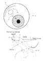
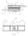
- FIG. 1schematically illustrates a drainage device for reducing intraocular pressure, according to one aspect of the disclosure
- FIGS. 2A and 2Bschematically illustrate an exemplary drainage device implanted in an eye, according to one aspect of the disclosure
- FIG. 3schematically illustrates a drainage device, according to another aspect of the present disclosure
- FIG. 4schematically illustrates a cross-sectional view of a drainage device, according to one aspect of the disclosure
- FIGS. 5A-5Cschematically illustrates various views of a drainage device, according to another aspect of the disclosure.
- FIGS. 6-10schematically illustrate a drainage device, according to various embodiments of the present disclosure
- FIGS. 11A and 11Bschematically illustrate an outlet tubular member for a drainage device as shown in FIG. 10 , according to one embodiment of the present disclosure
- FIGS. 12A and 12Bschematically illustrate an outlet tubular member for a drainage device as shown in FIG. 10 , according to another embodiment of the present disclosure
- FIG. 13Aschematically illustrates a cross-sectional view of a flow resistance arrangement housed in a housing of a drainage device, according to one embodiment of the present disclosure
- FIG. 13Bschematically illustrates a cross-sectional view of a flow resistance arrangement housed in a outlet tubular member of a drainage device, according to one embodiment of the present disclosure.
- FIG. 14schematically illustrates a method of manufacturing a drainage device, according to one aspect of the present disclosure.
- FIG. 1schematically illustrates an implantable ocular drainage device, generally designated as element 30 , according to one aspect of the present disclosure.
- the drainage device 30generally comprises a tubular body 32 and an outlet assembly 34 having a head portion 36 .
- the tubular body 32includes an inlet end 44 and a longitudinally-opposed outlet end 42 , and is configured to direct a fluid between the inlet 44 and outlet 42 ends.
- At least a portion of the tubular body 32 of the drainage device 30is implantable into the anterior chamber of an eye for draining aqueous humor therefrom (see, e.g., FIGS. 2A and 2B ).
- Representative configurations of such drainage devices of the general type disclosed hereinare disclosed, for example, in U.S. Patent Application Publication No. US 2010/0057055 and U.S. Pat. No. 7,641,627, each to Camras et al., and each of which is incorporated herein by reference.
- the tubular body 32 of the drainage device 30is substantially cylindrical and hollow, and has a proximal (outlet) end 42 and a distal (inlet) end 44 .
- the tubular body 32defines a lumen 46 that extends between the proximal end 42 and the distal end 44 with the distal end defining at least one opening 48 communicating with the lumen 46 .
- the at least one opening 48is configured to provide a fluid inlet at the distal end 44 of the tubular body 32 .
- the distal end 44 of the tubular body 32may be beveled (see, e.g., FIG. 4 ) for facilitating entry of the distal end 44 into the anterior chamber or other portion of the eye.
- the lumen 46forms at least a portion of a flow path that permits the drainage of aqueous humor from the anterior chamber of the eye to a location or drainage site external to the anterior chamber.
- the external location/drainage sitemay be an external ocular surface of the eye.
- the external location/drainage sitemay include another chamber within the eye, the subconjunctival space, the suprachoroidal space, or the like.
- the tubular body 32has a length sufficient to provide fluid communication between the anterior chamber of the eye and the fornix or cul-de-sac region under the eyelid to allow aqueous humor to flow from the anterior chamber through the lumen 46 and into the tear film associated with the eye when the drainage device 30 is implanted in or attached to the eye.
- the tubular body 32 of the drainage device 30may have a minimum length, for example, of at least about 3 mm for the outlet assembly 34 to be positioned about the fornix or cul-de-sac region under the eyelid.
- the tubular body 32may have a length of between about 4 mm and about 9 mm for adult humans.
- the tubular body 32may be provided in a standard length that may then be cut to size by the surgeon prior to implantation. In use, the tubular body 32 may lie substantially underneath the conjunctiva with the distal (input) end disposed in the anterior (or posterior) chamber of the eye (see, e.g., FIG. 2B ).
- the dimensions and deployment location of the drainage device 30may vary considerably depending on the location to which the aqueous humor drained from the anterior chamber is directed.
- the transverse/lateral cross-sectional shape of the tubular body 32in addition to circular, may be other suitable shapes such as, for example, oval, square, trapezoidal, rectangular, or any combination thereof.
- the cross-sectional size of the lumen 46 defined by the tubular body 32may vary to selectively alter the fluid flow characteristics of the aqueous humor.
- a relatively small cross-sectional sizecan be used to restrict the fluid flow of the aqueous humor.
- the cross-sectional dimension of the lumen 46may range, for example, from about 0.05 mm to about 1.0 mm.
- An anchoring device or arrangementsuch as one or more barbs (not shown) may be provided, for example, adjacent the distal end 44 of the tubular body 32 and/or in engagement with the housing or head portion 36 of the drainage device 30 .
- the barbscan extend from a portion of the outer surface of the tubular body 32 or from an outer surface of the housing/head portion 36 , for contact with the sclera when the drainage device 30 is implanted or engaged with the eye.
- the barbsare adapted to engage the sclera and provide stability until biointegration of the tubular body 32 and/or the housing/head portion 36 in the subconjunctival space.
- the barbsmay be formed as part of the tubular body 32 /head portion 36 of the drainage device 30 during manufacture or may be subsequently fused or bonded to the tubular body 32 /head portion 36 in an appropriate manner.
- the anchoring device or arrangementmay comprise one or more suture bars 50 (see, e.g., FIGS. 1 and 3 ) may extend outwardly of the tubular body 32 , between the proximal and distal ends 42 , 44 thereof, and/or outwardly of the housing/head portion 36 , wherein sutures (not shown) may be engaged between the sclera and the suture bars 50 to otherwise secure the tubular body 32 /housing or head portion 36 /drainage device 30 to the eye.
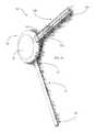
- the head portion 36 of the outlet assembly 34defines an interior cavity 52 .
- the head portion 36is integral with, or attached to, the proximal (outlet) end 42 of the tubular body 32 such that the cavity 52 is in fluid communication with the lumen 46 of the tubular body 32 so as to receive a flow of the aqueous humor therefrom.
- the head portion 36 and the tubular body 32may be formed integrally as a single unit. Alternatively, each component may be formed separately from the other and cooperate, when assembled, to define the interior cavity 52 .
- the head portion 36may be dome-shaped (or convex) to provide a substantially continuous transition surface from along an outer surface of the head portion 36 to the surface of the eye (i.e., the convex curvature is configured to make a smooth transition to the surface of the eye), for example, in instances where the head portion is configured to lie on the conjunctiva.
- the convex curvatureis configured to make a smooth transition to the surface of the eye
- Such a configuration/shape of the head portion 36may be better tolerated by the patient, if the head portion does not feel like a foreign object in the eye in relation to the eyelid. However, such a configuration may also be placed or lie subconjunctivally.
- Other shapes of the head portion 36may be suitable and appropriate for providing similar sensory perception for the user.
- a minimally protruding, substantially flat head portion 36 with rounded edgesmay be equally well tolerated.
- the plan view of the head portionmay be round or ovular (see, e.g., FIGS. 1, 3, 5A-5C, 6-8, and 10 ) or square or rectangular (see, e.g., FIG. 9 ).
- the inner (convex) surface of the head portion 36may be flat or curved (or a combination of both), as appropriate, to correspond to the shape of the external surface of the sclera, if the drainage device 30 is to be positioned subconjunctivally. In general, a subconjunctival placement of at least the head portion 36 may result in a lower risk of extrusion.
- the drainage device 30may comprise a filter 40 (see, e.g., FIG. 4 ) and/or a flow control device 39 (see, e.g., FIG. 13 ) for maintaining and/or controlling intraocular pressure and for allowing for a more physiological dynamic of the aqueous humor.
- the head portion 36 of the outlet assembly 34may be configured to house the flow control device 39 and/or the filter 40 , or may otherwise define an opening for receiving the flow control device 39 , through which opening the filter 40 may also be inserted into and/or removed from the head portion 36 .
- FIG. 4schematically illustrates, for example, a filter 40 at least partially disposed within the head portion 36 and/or the lumen 46 at the proximal end 42 of the tubular body 32 of the drainage device 30 .
- the filter 40may be configured as an elongate member having a distal inflow end 44 and a proximal outflow end 42 .
- the filter 40may be configured to extend laterally across the lumen 46 such that the lumenal passage of the tubular body 32 is closed or substantially closed by the filter 40 .
- the aqueous humor flowing through the lumen 46is therefore directed through the filter 40 , wherein the filter 40 filters the aqueous humor to prevent bacterial migration in either direction along the lumen.
- the filter 40may also be configured to regulate or at least facilitate the regulation of intraocular pressure by providing a predetermined resistance to outflow of aqueous humor from the anterior chamber of the eye to the external location (i.e., into the tear film about the exterior surface of the eye).
- the filter 40may be configured as a resistive component for the flow of aqueous humor. That is, the filter can provide particular flow rate of aqueous humor by selecting filter characteristics such as a predetermined number and size of pores and a selected overall length of the filter 40 (i.e., the flow path). These parameters, either separately or in combination, may be configured to provide an appropriate resistance to the flow of aqueous humor sufficient to reduce and maintain intraocular pressure, while preventing ocular hypotony.
- the filter 40may have a gradient of pore sizes along the length of the filter 40 .
- the pore sizemay continually decrease from the distal end 44 of the filter 40 to the proximal end 42 in order to prevent debris accumulation at the distal (inlet) end 44 of the filter 40 .
- Larger pores sizes at the distal end 44 and at the proximal end 42 of the filter 40may provide a pore gradient, which may help to reduce the effect of clogging on the outflow resistance.
- a representative filter 40 or a layer or portion thereofmay have a pore size of, for example, 0.5 ⁇ m or less to minimize or prevent bacterial migration therethrough. In instances where the filter 40 comprises multiple layers or portions, other layers or portions may have a pore size greater than 0.5 ⁇ m in order to reduce debris or relatively large contaminants.
- the filter 40may be removable and replaceable, and may be facilitated by external access to the outlet assembly 34 , or by external access to the tubular body 32 by way of the outlet assembly 34 , without disrupting the position of the drainage device 30 (i.e., the tubular body 32 thereof) in the eye.
- the ocular pressurecan be regulated by selecting a filter configuration that provides a selected aqueous humor flow rate.
- the filter 40may be configured to form a permanent element of the drainage device 30 .
- a flow control device 39may be housed by, in fluid communication with, or otherwise operably engaged with the head portion 36 (i.e., a housing defined and provided by the head portion 36 ). If the filter 40 is implemented in such aspects, the filter 40 may be disposed in fluid communication between the inlet (distal) end 44 of the tubular body 32 and the flow control device 39 , with the filter 40 being configured to filter contaminants from the aqueous humor prior to the flow control device 39 .
- the filter 40may be engaged with the housing of the head portion 36 subsequent to the outlet (proximal) end 42 of the tubular body (or “tube”) 30 , and wherein the housing of the head portion 36 is configured such that the flow control device 39 operably engaged therewith is removable or replaceable with respect to the housing, so as to also allow the filter 40 to be removed or replaced.
- the filter 40may be disposed in fluid communication with the flow control device 39 , opposite to the outlet (proximal) end 42 of the tubular body 32 from the flow control device 39 , wherein the filter 40 is configured to filter contaminants from any backflow to the flow control device 39 .
- the filter 40may be engaged with the housing of the head portion 36 subsequent to the flow control device 39 , and wherein the housing may be configured such that the filter 40 engaged therewith subsequent to the flow control device 39 is removable or replaceable with respect to the housing.
- a filter 40may be disposed both upstream and downstream of the flow control device 39 (see, e.g., a dual filter configuration housed by the head portion 36 , as shown in FIG. 13A ).
- Representative configurations of filters and flow control devices associated with drainage devices of the type disclosed hereinare disclosed, for example, in U.S. patent application Ser. No. 14/473,228, filed Aug. 29, 2014; and Ser. No. 14/826,866; filed Aug. 14, 2015, each to Camras et al., and each of which is incorporated herein by reference.
- the flow control device 39may define a conduit in communication between the cavity and the drainage site (i.e., wherein the flow control device 39 is engaged with the housing/head portion 36 or, according to some aspects of the disclosure, the tubular member 100 ), wherein the conduit may be dilatable in response to the intraocular pressure being above a preselected pressure by controlling the flow of the aqueous humor from the cavity 52 and through the distal end of the channel 150 to the drainage site.
- the flow control device 39may comprise a relatively thin and flexible membrane defining a conduit 38 in the form of an elongate slit (not shown), wherein the flexible membrane is configured to deform about a medial portion along the length of the slit, in response to elevated intraocular pressure, to allow aqueous humor to exit the drainage device 30 .
- the flow control device 39may comprise an elongate or relatively thick portion defining a conduit 38 extending through the thickness.
- the conduit 38is dilatable in response to the intraocular pressure being above a preselected or threshold pressure, to increase the flow or to decrease resistance to flow of the aqueous humor through the conduit 38 to the external location or drainage site (i.e., the external ocular surface) and to reduce and/or stabilize the intraocular pressure to no greater than the preselected pressure.
- the configuration of the dilatable conduit 38may be determined according to a preselected intraocular pressure, wherein the preselected ocular pressure may be a factor of, for example, the patient's age, physical characteristics, characteristics of the eye, advancement of the condition, particular physiological dynamics, or the like that are particular to a particular patient.
- the lateral cross-section of the conduit 38may take different forms such as, for example, circular, ovular, square, rectangular, or any other suitable shape, whether regular or irregular.
- the flow control device 39may be comprised of a flexible biocompatible material such as, for example, polyurethane or silicone.
- the flow control device 39or the material from which the flow control device 39 is comprised, may be configured to be responsive, for example, to an output of a laser device (not shown) so as to form or open additional dilatable channels therein or to attach components together. That is, a laser light output directed at the material comprising the flow control device 39 may cause the formation or opening of additional conduits 38 , as necessary or desired for controlling the flow of aqueous humor from the eye, and thus controlling the intraocular pressure.
- the flow control device 39may also be configured to be responsive, for instance, to the output of the laser device to seal or constrict a conduit 38 defined thereby. That is, one or more of the conduits 38 can be sealed or constricted, as necessary or desired, to control the flow or manipulate the resistance to flow of aqueous humor from the eye.
- the laser modification of the conduits defined by the flow control device 39 , or the material from which the flow control device 39 is comprisedmay be accomplished in situ, with the drainage device 30 in place with respect to the eye.
- the flow control device 39may be fabricated by any suitable microfabrication technique or process, in addition or in the alternative to the responsiveness thereof to the output of a laser device. For example, photolithography/deposition techniques, casting, molding, or any other suitable technique or combinations thereof may be implemented for forming the flow control device 39 .
- the head portion/housing 36may be configured to define a cavity 52 therein.
- the head portion/housing 36may be comprised of two or more portions which, when assembled, cooperate to define the cavity 52 therein (see, e.g., FIG. 5B ).
- the cavity 52in communication with the lumen 46 of the tubular body (or a first tube) 32 , is thus configured to receive the aqueous humor from the anterior chamber through the proximal outflow end 42 of the tubular body 32 .
- the aqueous humor received by the cavity 52may then be drained from the cavity 52 to a drainage site disposed distally to the cavity 52 .
- the drainage device 30may further include an elongate tubular member (or a second tube) 100 having opposed proximal and distal ends 110 , 120 , with the tubular member 100 further defining a longitudinally-extending channel 150 .
- the proximal end 110 of the tubular member 100is engaged with or disposed in the housing/head portion 36 , independently of the tubular body 32 , such that the channel 150 defined by the tubular member 100 is in fluid communication with the cavity 52 , and such that the distal end 120 is spaced apart from the housing/head portion 36 .
- the tubular member 100is configured to be engaged with the housing/head portion 36
- the housing/head portion 36is configured to be separately, discretely, and independently engaged with the tubular body 32
- the channel 150 defined by the tubular member 100is configured to receive the aqueous humor from the cavity 52 through a proximal opening at the proximal end 110 and to direct the aqueous humor through a distal opening at the distal end 120 to a drainage site disposed distally to, externally to, or otherwise away from the anterior chamber and the housing/head portion 36 .
- the tubular body 32may extend along a first axis and the tubular member 100 may extend along a second axis, where the second axis is perpendicular to the first axis.
- the tubular member 100may provide a single outlet for the aqueous humor from the cavity 52 of the housing/head portion 36 as shown, for example, in FIGS. 3, 4 , and 8 - 10 . That is, the single tubular member 100 having the proximal end 110 thereof engaged with the housing/head portion 36 and extending therefrom, may define a single channel 150 in communication the cavity 52 for directing the aqueous humor to the distal drainage site away from the housing/head portion 36 .
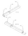
- the tubular member 100may be configured such that the channel 150 is bifurcated along a portion of the tubular member 100 , distal to the housing/head portion 36 , to form two (or more) outlet channels 160 , 170 (see, e.g., FIGS. 10, 11A -B, and 12 A-B).
- the channel 150may extend from the cavity 52 and to each of the outlet channels 160 , 170 , wherein the outlet channels 160 , 170 then extend to the distal end 120 of the tubular member 100 .
- the outlet channels 160 , 170may each extend directly from the cavity 52 , wherein the single channel 150 is not present in the tubular member 100 .
- the tubular member 100may lie on the conjunctival surface when the drainage device 30 is implanted, the tubular member 100 may have an appropriate coating applied thereto so as to facilitate comfort of the patient (i.e., by lowering the sensation of the tubular member 100 being a foreign object in the eye).
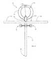
- a diverter 200may be engaged with the distal end 120 of the tubular member 100 , with the diverter 200 having at least two elongate diversion members 210 , 220 extending from the distal end 120 of the tubular member 100 .
- each diversion member 210 , 220may define a diversion channel 230 , 240 in communication with the channel 150 defined by the tubular member 100 (see, e.g., FIGS. 1, 5A-5C, and 6 ).
- the diverter 200 or the diversion members 201 , 220 thereofmay be configured, for example, to cooperate with the tubular member 100 to form a Y-arrangement or a T-arrangement (see, e.g., the various “T” arrangements shown in FIGS. 1, 5A-5C, and 6 ).
- the drainage device 30may be configured such that the tubular body 32 and the housing/head portion 36 are implanted under the conjunctival surface (i.e., to prevent or minimize the risk of extrusion), while the tubular member 100 and/or the diverter 200 are configured, for example, to cooperate to extend out of the plane of the housing/head portion 36 , such that the tubular member 100 and/or diverter 200 /diversion members 201 , 220 lie on top of the conjunctival surface when the drainage device 30 is implanted (see, e.g., the configurations shown in FIGS. 5A-5C, and 6 ) to direct the aqueous humor to the drainage site(s).
- each diversion member 210 , 220includes a proximal end 210 A, 220 A engaged with the distal end 120 of the tubular member 100 , and an opposing distal end 210 B, 220 B (see, e.g., FIG. 1 ).
- the tubular member 100is configured to only allow flow of the aqueous humor outwardly of the distal end 120 thereof from the cavity 52 .
- the diverter 200may lie on the conjunctival surface when the drainage device 30 is implanted, the diverter 200 may have an appropriate coating applied thereto so as to facilitate comfort of the patient (i.e., by lowering the sensation of the tubular member 100 /diverter 200 being a foreign object in the eye).
- the tubular member 100 and/or the diverter 200may be configured to control a flow of the aqueous humor from the cavity 52 to the drainage site (i.e., the external ocular surface of the eye). That is, in some instances, the tubular member 100 and/or the diversion member(s) 210 , 220 may include a flow resistance element or arrangement (i.e., filter 40 and/or flow control device 39 ) configured to control or regulate the flow of the aqueous humor from the cavity 52 . According to some aspects, the flow resistance arrangement may comprise a slit or slit valve arrangement disposed about the distal end(s) of the tubular member 100 or the diverter 200 .
- the flow resistance element or arrangementmay include one or more of a flow control device 39 , a filter or filter device 40 , or a flow control device 39 and a filter or filter device 40 , engaged with the tubular member 100 or the diverter 200 , or between the housing/head portion 36 and the proximal end 110 of the tubular member 100 .
- the flow control device 39 and/or filter 40may be configured to be removable or replaceable with respect to the housing/head portion 36 , the tubular member 100 and/or the diversion member(s) 210 , 220 .
- the tubular member 100 and/or the diversion member(s) 210 , 220may be configured to be collapsible on removal of the flow resistance element or arrangement, so as to, for example, prevent hypotony or backflow of contaminants through the diversion member(s) 210 , 220 or tubular member 100 , into and toward the cavity 52 and the anterior chamber of the eye.
- An appropriate toolconfigured to engage the flow resistance element or arrangement for removal or replacement with respect to the tubular member 100 and/or the diversion member(s) 210 , 220 . In this manner, the risk of infection may be lowered.
- one or more filters 40may be disposed in fluid communication between the flow control device 39 and the distal end 120 of the tubular member 100 , wherein the filter(s) 40 is/are configured to filter contaminants from any backflow to the flow control device 39 from the drainage site. In such instances, the filter 40 may be engaged with the tubular member 100 subsequent to the housing/head portion 36 .
- the tubular member 100 having the filter 40 and/or the flow control device 39 engaged therewithmay be configured to be removable or replaceable with respect to the housing/head portion 36 .
- the diverter 200 or diversion members 210 , 220 having the filter 40 and/or the flow control device 39 engaged therewith, for example, within one of the diversion channels 230 , 240may be configured to be removable or replaceable with respect to the tubular member 100 .
- the filter 40 and/or flow control device 39may be removable or replaceable with respect to the tubular member 100 and/or the diverter 200 , upon removal of the tubular member 100 from engagement with the housing/head portion 36 , or upon removal of the diverter 200 from engagement with the tubular member 100 , as appropriate.
- a removal/replacement proceduremay involve, for example, a clamp applied to the housing or interface with the tubular member to cease any flow of the aqueous humor from the anterior chamber or cavity, while forceps can be used to remove and replace the tubular element.
- the filter(s) 40 and/or flow control device 39may include one or more provisions for facilitating removability and replaceability, for example, with the aide of an appropriate tool.
- the filter(s) 40 and/or flow control device 39may include a slot or protrusion to facilitate interaction with an appropriate removal/replacement tool, whether forceps or otherwise.
- the flow resistance element or arrangementi.e., one or more filters 40 and/or a flow control device 40
- the tubular member 100 or diverter 200 receiving and housing the samemay be configured in different manners to facilitate removal/replacement.
- the flow resistance element or arrangementmay be configured to expand in size upon insertion into the tubular member 100 and/or the diversion member(s) 210 , 220 for securement therein.
- the resistance to flow provided by the flow resistance element or arrangementmay be adjusted or modified in different manners.
- a length or inner diameter of the tubular member 100 and/or the diversion members 210 , 220may be adjusted, or different multiples or configurations of flow resistance elements (i.e., filters 40 and/or flow control devices 39 ), each having an effect on the resistance to flow, may be implemented.
- flow resistance elementsi.e., filters 40 and/or flow control devices 39
- a filter with smaller pore size, lower pore density, thicker or/and smaller surface areawill result in increased flow resistance, thereby decreasing the flow of aqueous humor therethrough, while a filter with larger pore size, higher pore density, thinner and/or larger surface area will result in decreased flow resistance, thereby increasing the flow of aqueous humor therethrough.
- suturesmay be used to constrict the tubular member 100 and/or the diversion member(s) 210 , 220 to increase resistance to flow of the aqueous humor, while, for example, a laser pulse or cutting device may be used to loosen or cut the suture(s) to otherwise decrease resistance to flow of the aqueous humor.
- the bifurcated channels 160 , 170 of the tubular member 100 and/or the diversion channels 230 , 240 of the diverter 200may be configured to facilitate flushing/cleaning in situ.
- one of the bifurcated channels 160 , 170 of the tubular member 100may be configured to allow an inflow from the distal end 120 toward and up to the cavity 52 such that the tubular member 100 can be flushed to remove debris.
- the housing/head portion 36 or the interface between the housing and the tubular member 100can be engaged by a clamp to prevent flow into or out of the housing via the tubular member 100 .
- a cleaning solutioncan then be directed into the one of the bifurcated channels 160 , 170 configured to allow an inflow, such that the cleaning solution is directed inwardly along that bifurcated channel 160 , 170 , and out through the other bifurcated channel 160 , 170 , such that any contaminants are flushed out of the tubular member 100 .
- one of the diversion members 210 , 220may be configured to allow an inflow from the distal end 210 B, 220 B thereof, wherein the inflow into the one of the diversion members 210 , 220 may be used to flush out the diversion members 210 , 220 , without the inflow entering the distal end of the channel 150 defined by the tubular member 100 . That is, the distal end 120 of the tubular member 100 can be engaged by a clamp to prevent flow into or out of the tubular member 100 .
- a cleaning solutioncan then be directed into the one of the diversion channels 230 , 240 configured to allow an inflow, such that the cleaning solution is directed inwardly along that diversion channel 230 , 240 , and out through the other diversion channel 230 , 240 , such that any contaminants are flushed out of the diverter 200 .
- the tube/tubular body 32 and the outlet assembly (housing/head portion 36 , tubular member 100 , and diverter 200 ) of the embodiments of drainage device 30may be formed from materials having good biocompatibility and durability, and which are sufficiently flexible.
- Suitable materialsinclude a material selected from the group consisting of silicone, acrylic, polyimide, polypropylene, polymethyl methacrylate, polytetrafluoroethylene, hydrogels, polyolefin, polyolefin resins such as polyethylene, polyisobutylene, ethylene-vinyl acetate copolymer, polynorbornene, polyvinylchloride, polyester, polyvinyl alcohol, polyvinyl pyrolidone, polyethersulfone (PES), poly(styrene-isobutyl-styrene), polysilicon, polyurethane, polycarbonate urethane, glass and ceramics such as alumina and titania, metals such as stainless steel, titanium, gold, silver, platinum or nitinol, collagen or chemically-treated collagen, hydroxyapetite, natural and synthetic rubbers such as polybutadiene, polyisoprene, SBR (Styrene Butadiene Rubber), and SIR,
- At least a portion of the filter(s) 40has a pore size that is sufficiently small to prevent ingress or backflow of microorganisms, such as bacteria, viruses, fungi and spores thereof, from entering the lumen 46 , so as to minimize the opportunity for reflux infection in the eye.
- a pore size of less than about 0.4 ⁇ m or 0.5 ⁇ mis sufficiently small to prevent ingress or backflow of microorganisms past the filter(s) 40 .
- the filter 40may comprise a microporous/nanoporous membrane or polymer network, fiber network, or microcapsular material having a network of pores.
- Microporous filter membranes suitable for use with ophthalmic devicesinclude micropore filter membranes (polycarbonate, polyethersulfone, polyvinylidene fluoride, polytetrafluoroethylene), porous hydrogels (polyacrylamide, alginate, polyhydroxyethylmethacrylate), and microperforated silicone or polyvinyl polymer, such as polyvinyl alcohol, which is expandable within the lumen 46 .
- Other suitable polymersinclude a polyolefin polymer, an ethylene-vinyl alcohol copolymer, a polyacrylonitrile polymer, a polyurethane polymer, a cellulose polymer, cellulose acetate polymer, a polyimide polymer, and a polyamide polymer.
- Filter membrane nanotechnologymay also be useful to fabricate microporous membranes to be biocompatible, non-degradable, and immune-isolating.
- Other materialssuch as ceramics, polymers and metals, such as titanium, may also be suitable for the filter.
- the filtersmay be created using additive manufacturing, lithography or electrospinning.
- the filter 40may have an antibiotic coating to prevent contamination during replacement. Suitable coatings for the filter are described in co-pending U.S. Patent Application Publication No. 2010/0057055, the contents of which are hereby incorporated by reference in their entirety.
- At least a portion of the external surfaces of the tube/tubular body 32 , the suture bars 50 , the inner surface of the head portion 36 , the tubular member 100 , and/or the diverter 200 of the drainage device 30may be coated with a porous cellular ingrowth material.
- the porous cellular ingrowth materialis coated on at least the portion of the drainage device 30 that is in contact with the sclera and conjunctiva when the drainage device 30 is implanted so as to promote ingrowth with respect to that selected portion of the drainage device 30 .
- the portion of the tubular member 100 extending through or otherwise in contact with the conjunctivamay include the porous cellular ingrowth material so as to promote ingrowth, integration, and conjunctival closure with respect thereto.
- a collar 180see, e.g., FIG.
- tubular member 100 or diverter 200can be removed and replaced without disturbing the conjunctiva (i.e., such that the tubular member 100 /diverter 200 is not removed or replaced within the conjunctival space). Such a provision may thus reduce the risk of infection and/or prevent epithelial downgrowth.
- the porous cellular ingrowth materialmay be applied in the form of a coating, such as a hydroxyapatite or porous polyethylene, which serves to promote cell adhesion.
- a componentsuch as the collar 180 , may be comprised of a porous cellular ingrowth material, such as porous polyethylene. Selected growth factors may be adsorbed such that the tube/tubular body 32 , the suture bars 50 , and the housing/head portion 36 of the drainage device 30 may be securely anchored in position. This enables the drainage device 30 to resist in situ motion and displacement.
- the body of the drainage device 30may include surface alterations, such as texturing, roughening or other patterned or non-patterned irregularities.
- the remaining surfaces of the drainage device 30may be coated with a bio-inert surface coating to enhance surface biocompatibility.
- a bio-inert surface coatingmay include bio-inert polymer coatings such as phosphoryl choline (PC), polyethylene glycol (PEG), sulfobetaine (SB), carboxybetaine (CB), and polyethylene oxide (PEO). These polymer coatings down-regulate deleterious biological reactions, primarily by attracting a large and stable hydration shell when grafted onto a surface.
- Bio-inert surface coatingsmay be further modified with biologically active molecules such as heparin, spermine, surfactants, proteases or other enzymes, or other biocompatible chemicals amendable to surface immobilization.
- biologically active moleculessuch as heparin, spermine, surfactants, proteases or other enzymes, or other biocompatible chemicals amendable to surface immobilization.
- PEOalso is amenable to end-group coupling for surface immobilization of the biologically active molecules.
- the addition of such bioactive moleculescould advantageously impart specific desired functionality, for example, allowing a further increase in the hydrophilicity of the surface.
- the coating for the drainage device 30can also comprise material that includes a therapeutic agent, as well as antifibrotic and/or antimicrobial and/or anti-fouling agents.
- the therapeutic agentcan be selected from the group consisting of heparin, selenium, TGF-beta, an intraocular pressure-lowering drug, and an anti-proliferative agent.
- the coatingscan be, for example, a drug eluting coating, an antithrombogenic coating, and/or a lubricious coating.
- Materials that may be used for a drug-eluting coatinginclude parylene C, poly(butyl methacrylate), poly(methyl methacrylate), polyethylene-co-vinyl acetate, and other materials known in the art.
- Anti-microbial coatingsmay include, for example selenium, silver, melimine, or fimbrolides or other quorum sensing inhibitors.
- these agentsmay be incorporated into the filter material or other components of the drainage device 30 via covalent, metallic, ionic, or non-covalent bonding, or by surface adsorption.
- Another aspect of the disclosure hereinis directed to a method of manufacturing an apparatus for draining aqueous humor from an eye for reducing and/or stabilizing intraocular pressure, as shown, for example, in FIG. 14 .
- Such a methodcomprises engaging an outlet end of a tube into fluid communication with a cavity defined by a housing, wherein the outlet end extends to an inlet end adapted to be in fluid communication with the anterior chamber of the eye, and wherein the tube is adapted to direct a flow of aqueous humor from the anterior chamber and through the inlet end and to the outlet end such that the aqueous humor is received by the cavity (block 300 ).
- a proximal end of an elongate tubular memberis engaged with the housing, independently of the tube/tubular body 32 , wherein the tubular member has a distal end opposing the proximal end and defines a longitudinally-extending channel, such that the channel defined by the tubular member is in fluid communication with the cavity and such that the distal end is spaced apart from the housing, and wherein the channel is configured to receive the aqueous humor from the cavity and to direct the aqueous humor through the distal end to a drainage site disposed distally to the anterior chamber and to the housing.
- Such a method of manufacturemay be realized in conjunction with the drainage device(s) and components thereof as disclosed herein.
- a flow control devicemay be operably engaged with the housing or the tubular member, wherein the flow control device is configured to control the flow of the aqueous humor from the cavity and through the distal end of the channel to the drainage site.
- a flow control devicedefining a conduit in communication between the cavity and the drainage site, may be engaged with the housing, wherein the conduit is dilatable in response to the intraocular pressure being above a preselected pressure, so as to increase the flow or to decrease resistance to the flow of the aqueous humor through the conduit to the drainage site and to reduce the intraocular pressure to no greater than the preselected pressure.
- a filter devicemay be disposed in fluid communication between the inlet end of the tube and the flow control device, wherein the filter device is configured to filter contaminants from the aqueous humor prior to the flow control device.
- the filter devicemay be with the housing subsequent to the outlet end of the tube, with the housing being configured such that the flow control device operably engaged therewith is removable or replaceable with respect to the housing, so as to allow the filter device to be removed or replaced.
- the filter devicemay be disposed in fluid communication between the flow control device and the distal end of the tubular member, with the filter device being configured to filter contaminants from any backflow to the flow control device from the drainage site.
- the filter devicemay be engaged with the housing subsequent to the flow control device, with the housing being configured such that the filter device engaged therewith is removable or replaceable with respect to the housing.
- the filter devicemay be engaged with the tubular member subsequent to the housing, particularly wherein the tubular member is engaged with the filter device such that the tubular member and the filter device are configured to be removable or replaceable with respect to the housing, and such that the filter device is configured to be removable or replaceable with respect to the tubular member.
- an anchoring devicemay be operably engaged with the tube or the housing, with the anchoring device being configured to engage the eye subconjunctivally so as to secure at least the tube or the housing to the eye.
- a flow resistance elementmay be engaged with the tubular member, with the flow resistance element including a flow control device, a filter device, or a flow control device and a filter device, wherein the flow resistance element is configured to be removable or replaceable with respect to the tubular member, and wherein the tubular member is configured to be collapsible on removal of the flow resistance element.
- a medicinal agentmay be applied to the flow resistance element for preventing occlusion or bacterial contamination thereof by inhibiting the formation of fibrotic membranes, inflammatory membranes, bacterial adhesions, or biofilms.
- an external portion of the elongate tubular membermay be coated for increasing patient comfort.
- the proximal end of the elongate tubular membermay be engaged with the housing, wherein the channel defined by the tubular member is bifurcated along a portion of the tubular member distal to the housing.
- one of the bifurcated channelsmay be configured to allow an inflow from the distal end to the cavity.
- a divertermay be engaged with the distal end of the tubular member, with the diverter having at least two elongate diversion members extending from the distal end of the tubular member, and with each diversion member defining a diversion channel in communication with the channel defined by the tubular member.
- the divertermay be configured to cooperate with the tubular member to form a Y-arrangement or a T-arrangement.
- each diversion memberincludes a proximal end engaged with the distal end of the tubular member, and an opposing distal end, wherein the tubular member is configured to only allow flow of the aqueous humor outwardly of the distal end thereof from the cavity.
- one of the diversion membersmay be configured to allow an inflow from the distal end thereof, wherein the inflow into the one of the diversion members is used to flush out the diversion members, without the inflow entering the distal end of the channel defined by the tubular member.
- tubular member 100 and/or the diverter 200may be used to infuse drugs, medications, or other substances back through the drainage device 30 and into the anterior chamber of the eye.
- tubular member 100 and/or the diverter 200may be at least partially porous so as to allow the aqueous humor to be discharged from the cavity 52 of the housing more uniformly onto the ocular surface, which may help to alleviate a dry eye condition. Therefore, it is to be understood that the disclosure is not to be limited to the specific aspects disclosed herein and that modifications and other aspects are intended to be included within the scope of the appended claims. Although specific terms are employed herein, they are used in a generic and descriptive sense only and not for purposes of limitation.
Landscapes
- Health & Medical Sciences (AREA)
- Ophthalmology & Optometry (AREA)
- Heart & Thoracic Surgery (AREA)
- Surgery (AREA)
- Engineering & Computer Science (AREA)
- Biomedical Technology (AREA)
- Nuclear Medicine, Radiotherapy & Molecular Imaging (AREA)
- Vascular Medicine (AREA)
- Life Sciences & Earth Sciences (AREA)
- Animal Behavior & Ethology (AREA)
- General Health & Medical Sciences (AREA)
- Public Health (AREA)
- Veterinary Medicine (AREA)
- Prostheses (AREA)
Abstract
Description
Claims (38)
Priority Applications (5)
| Application Number | Priority Date | Filing Date | Title |
|---|---|---|---|
| US14/871,095US10524958B2 (en) | 2015-09-30 | 2015-09-30 | Method and apparatus for reducing intraocular pressure |
| JP2018516806AJP6766140B2 (en) | 2015-09-30 | 2016-09-23 | Equipment for reducing intraocular pressure and its manufacturing method |
| EP16777870.3AEP3355841A1 (en) | 2015-09-30 | 2016-09-23 | Apparatus for reducing intraocular pressure and manfacturing method therefor |
| CN201680069704.1ACN108366873A (en) | 2015-09-30 | 2016-09-23 | For reducing the equipment and its manufacturing method of intraocular pressure |
| PCT/US2016/053391WO2017058656A1 (en) | 2015-09-30 | 2016-09-23 | Apparatus for reducing intraocular pressure and manfacturing method therefor |
Applications Claiming Priority (1)
| Application Number | Priority Date | Filing Date | Title |
|---|---|---|---|
| US14/871,095US10524958B2 (en) | 2015-09-30 | 2015-09-30 | Method and apparatus for reducing intraocular pressure |
Publications (2)
| Publication Number | Publication Date |
|---|---|
| US20170087016A1 US20170087016A1 (en) | 2017-03-30 |
| US10524958B2true US10524958B2 (en) | 2020-01-07 |
Family
ID=57083392
Family Applications (1)
| Application Number | Title | Priority Date | Filing Date |
|---|---|---|---|
| US14/871,095Expired - Fee RelatedUS10524958B2 (en) | 2015-09-30 | 2015-09-30 | Method and apparatus for reducing intraocular pressure |
Country Status (5)
| Country | Link |
|---|---|
| US (1) | US10524958B2 (en) |
| EP (1) | EP3355841A1 (en) |
| JP (1) | JP6766140B2 (en) |
| CN (1) | CN108366873A (en) |
| WO (1) | WO2017058656A1 (en) |
Cited By (11)
| Publication number | Priority date | Publication date | Assignee | Title |
|---|---|---|---|---|
| US11291585B2 (en) | 2020-02-14 | 2022-04-05 | Shifamed Holdings, Llc | Shunting systems with rotation-based flow control assemblies, and associated systems and methods |
| US11419761B2 (en)* | 2020-07-22 | 2022-08-23 | The Eye Hospital Of Wenzhou Medical University | Glaucoma aqueous humor drainage device and glaucoma aqueous humor drainage method |
| US11517477B2 (en) | 2019-10-10 | 2022-12-06 | Shifamed Holdings, Llc | Adjustable flow glaucoma shunts and associated systems and methods |
| US11529258B2 (en) | 2020-01-23 | 2022-12-20 | Shifamed Holdings, Llc | Adjustable flow glaucoma shunts and associated systems and methods |
| US11596550B2 (en) | 2020-04-16 | 2023-03-07 | Shifamed Holdings, Llc | Adjustable glaucoma treatment devices and associated systems and methods |
| US11737920B2 (en) | 2020-02-18 | 2023-08-29 | Shifamed Holdings, Llc | Adjustable flow glaucoma shunts having non-linearly arranged flow control elements, and associated systems and methods |
| US11766355B2 (en) | 2020-03-19 | 2023-09-26 | Shifamed Holdings, Llc | Intraocular shunts with low-profile actuation elements and associated systems and methods |
| US11865283B2 (en) | 2021-01-22 | 2024-01-09 | Shifamed Holdings, Llc | Adjustable shunting systems with plate assemblies, and associated systems and methods |
| US12220350B2 (en) | 2017-07-20 | 2025-02-11 | Shifamed Holdings, Llc | Adjustable flow glaucoma shunts and methods for making and using same |
| US12226343B2 (en) | 2017-07-20 | 2025-02-18 | Shifamed Holdings, Llc | Adjustable flow glaucoma shunts and methods for making and using same |
| US12329682B2 (en) | 2019-01-18 | 2025-06-17 | Shifamed Holdings, Llc | Adjustable flow glaucoma shunts and methods for making and using same |
Families Citing this family (17)
| Publication number | Priority date | Publication date | Assignee | Title |
|---|---|---|---|---|
| US20180311075A1 (en)* | 2017-04-27 | 2018-11-01 | Camras Vision Inc. | System and a method for reducing pressure in a pressurized chamber |
| JP6529050B2 (en)* | 2017-10-23 | 2019-06-12 | 株式会社ドックスネット | Implant and implant system |
| US11246753B2 (en)* | 2017-11-08 | 2022-02-15 | Aquesys, Inc. | Manually adjustable intraocular flow regulation |
| AU2018372806B2 (en)* | 2017-11-21 | 2024-05-30 | Forsight Vision4, Inc. | Fluid exchange apparatus for expandable port delivery system and methods of use |
| US20190254873A1 (en)* | 2018-02-21 | 2019-08-22 | Camras Vision, Inc. | Systems and methods for reducing intraocular pressure |
| WO2019195419A1 (en) | 2018-04-03 | 2019-10-10 | Jack Chu | A new ocular device and method for glaucoma treatment |
| US10369049B1 (en) | 2018-08-17 | 2019-08-06 | Iridex Corporation | Probes having fiber taper and fluid collection channel for ophthalmic laser treatment |
| WO2020046054A1 (en)* | 2018-08-30 | 2020-03-05 | 사회복지법인 삼성생명공익재단 | Ocular disease implant device having easily changeable physical properties and shape |
| CN109199693A (en)* | 2018-09-28 | 2019-01-15 | 孙大卫 | A kind of glaucoma drainage device |
| CN109223302B (en)* | 2018-11-21 | 2020-12-25 | 中国人民解放军总医院 | Aqueous humor drainage device and manufacturing method thereof |
| EP3969094A1 (en)* | 2019-05-13 | 2022-03-23 | Medtronic Vascular, Inc. | Extended introducer for left radial access |
| CN114945392A (en) | 2019-11-08 | 2022-08-26 | 瑟梅德斯有限责任公司 | Fluid management system and method |
| CN110934684B (en)* | 2019-11-21 | 2021-03-30 | 浙江大学 | Glaucoma drainage valve with surface grafted anti-proliferative drug sustained-release coating and preparation method thereof |
| US20220313491A1 (en)* | 2021-04-02 | 2022-10-06 | Twenty Twenty Therapeutics Llc | Passive intraocular pressure control and associated systems, devices, and methods |
| USD1033637S1 (en) | 2022-01-24 | 2024-07-02 | Forsight Vision4, Inc. | Fluid exchange device |
| US20230310211A1 (en)* | 2022-03-29 | 2023-10-05 | W. L. Gore & Associates, Inc. | Biological fluid shunt devices and methods |
| CN120731060A (en)* | 2022-12-28 | 2025-09-30 | 亮白私人有限公司 | Glaucoma devices |
Citations (114)
| Publication number | Priority date | Publication date | Assignee | Title |
|---|---|---|---|---|
| US3788327A (en) | 1971-03-30 | 1974-01-29 | H Donowitz | Surgical implant device |
| EP0102747A1 (en) | 1982-07-28 | 1984-03-14 | Thomas C. White | Ocular pressure relief device |
| US4886488A (en) | 1987-08-06 | 1989-12-12 | White Thomas C | Glaucoma drainage the lacrimal system and method |
| US5041081A (en)* | 1990-05-18 | 1991-08-20 | Odrich Ronald B | Ocular implant for controlling glaucoma |
| US5127901A (en) | 1990-05-18 | 1992-07-07 | Odrich Ronald B | Implant with subconjunctival arch |
| US5171213A (en) | 1991-08-14 | 1992-12-15 | Price Jr Francis W | Technique for fistulization of the eye and an eye filtration prosthesis useful therefor |
| US5300020A (en) | 1991-05-31 | 1994-04-05 | Medflex Corporation | Surgically implantable device for glaucoma relief |
| US5346464A (en)* | 1992-03-10 | 1994-09-13 | Camras Carl B | Method and apparatus for reducing intraocular pressure |
| US5626558A (en) | 1995-05-05 | 1997-05-06 | Suson; John | Adjustable flow rate glaucoma shunt and method of using same |
| US5656026A (en) | 1995-10-27 | 1997-08-12 | Joseph; Neil H. | Method of in vitro testing one-way pressure gradient limiting valved glaucoma drainage implants |
| US5743868A (en) | 1994-02-14 | 1998-04-28 | Brown; Reay H. | Corneal pressure-regulating implant device |
| US5807302A (en) | 1996-04-01 | 1998-09-15 | Wandel; Thaddeus | Treatment of glaucoma |
| US5830173A (en) | 1994-12-12 | 1998-11-03 | Avery; Robert Logan | Intravitreal medicine delivery |
| US5882327A (en) | 1997-04-17 | 1999-03-16 | Jacob; Jean T. | Long-term glaucoma drainage implant |
| US6077299A (en) | 1998-06-22 | 2000-06-20 | Eyetronic, Llc | Non-invasively adjustable valve implant for the drainage of aqueous humor in glaucoma |
| WO2000064393A1 (en) | 1999-04-26 | 2000-11-02 | Lynch Mary G | Shunt device and method for treating glaucoma |
| US6261256B1 (en) | 1996-12-20 | 2001-07-17 | Abdul Mateen Ahmed | Pocket medical valve & method |
| US20020143284A1 (en)* | 2001-04-03 | 2002-10-03 | Hosheng Tu | Drug-releasing trabecular implant for glaucoma treatment |
| US20020169468A1 (en) | 2001-01-09 | 2002-11-14 | J.David Brown | Glaucoma treatment device and method |
| US6537241B1 (en) | 1997-08-08 | 2003-03-25 | Twin Star Medical, Inc. | System and method for site specific therapy |
| US6544208B2 (en) | 2000-12-29 | 2003-04-08 | C. Ross Ethier | Implantable shunt device |
| US6558342B1 (en) | 1999-06-02 | 2003-05-06 | Optonol Ltd. | Flow control device, introducer and method of implanting |
| US20040073156A1 (en)* | 2001-01-09 | 2004-04-15 | Brown J. David | Glaucoma treatment device and method |
| US20040127843A1 (en) | 2000-04-14 | 2004-07-01 | Hosheng Tu | Glaucoma implant with therapeutic agents |
| US20040215126A1 (en) | 2003-04-22 | 2004-10-28 | Ahmed A. Mateen | Device for treating glaucoma & method of manufacture |
| US20040249441A1 (en) | 2002-02-08 | 2004-12-09 | Miller Kathleen M. | Implantable or insertable medical device resistant to microbial growth and biofilm formation |
| US20040254521A1 (en) | 2003-06-16 | 2004-12-16 | Solx, Inc. | Shunt for the treatment of glaucoma |
| US20050049578A1 (en) | 2000-04-14 | 2005-03-03 | Hosheng Tu | Implantable ocular pump to reduce intraocular pressure |
| US20050119737A1 (en) | 2000-01-12 | 2005-06-02 | Bene Eric A. | Ocular implant and methods for making and using same |
| US20050240143A1 (en) | 2004-04-23 | 2005-10-27 | Dohlman Claes H | Shunt with enclosed pressure-relief valve |
| US20050240142A1 (en) | 2004-04-23 | 2005-10-27 | Dohlman Claes H | Dry eye treatment |
| US20060036207A1 (en) | 2004-02-24 | 2006-02-16 | Koonmen James P | System and method for treating glaucoma |
| US20060069340A1 (en) | 2003-06-16 | 2006-03-30 | Solx, Inc. | Shunt for the treatment of glaucoma |
| US20060116626A1 (en) | 2002-03-07 | 2006-06-01 | Gregory Smedley | Fluid infusion methods for glaucoma treatment |
| US20060189915A1 (en) | 2005-02-23 | 2006-08-24 | Camras Carl B | Method and apparatus for reducing intraocular pressure |
| US7118547B2 (en) | 2000-09-01 | 2006-10-10 | Ioltechnologie-Production | Glaucoma drain |
| US20060235367A1 (en) | 2002-12-27 | 2006-10-19 | Seisuke Takashima | Aqueous humor drainage implant for treatment glaucoma |
| US7135009B2 (en) | 2001-04-07 | 2006-11-14 | Glaukos Corporation | Glaucoma stent and methods thereof for glaucoma treatment |
| US20070004998A1 (en) | 2005-06-21 | 2007-01-04 | Rodgers M S | Glaucoma implant having MEMS flow module with flexing diaphragm for pressure regulation |
| US7192412B1 (en) | 2002-09-14 | 2007-03-20 | Glaukos Corporation | Targeted stent placement and multi-stent therapy |
| US20070156079A1 (en) | 2005-09-16 | 2007-07-05 | Bg Implant, Inc. | Glaucoma Treatment Devices and Methods |
| US20070254005A1 (en) | 2004-08-26 | 2007-11-01 | Pathak Chandraskekhar P | Implantable Tissue Compositions and Method |
| US20080228127A1 (en) | 2006-11-10 | 2008-09-18 | Glaukos Corporation | Uveoscleral shunt and methods for implanting same |
| US7458953B2 (en) | 2006-06-20 | 2008-12-02 | Gholam A. Peyman | Ocular drainage device |
| US20090036818A1 (en) | 2002-05-29 | 2009-02-05 | University Of Saskatchewan | Shunt and Method Treatment of Glaucoma |
| US20090117166A1 (en) | 2007-08-15 | 2009-05-07 | David Myung | Sequential coupling of biomolecule layers to polymers |
| WO2009105573A1 (en) | 2008-02-19 | 2009-08-27 | Cascade Ophthalmics | Intraocular pressure attenuation devices and methods |
| US20090326432A1 (en) | 2007-01-25 | 2009-12-31 | Wolfram Schmidt | Ocular implant |
| US7670310B2 (en) | 1997-11-20 | 2010-03-02 | Optonol Ltd | Flow regulating implants |
| US20100056979A1 (en) | 2000-04-14 | 2010-03-04 | Glaukos Corporation | Implantable ocular pump to reduce intraocular pressure |
| US20100057055A1 (en) | 2005-02-23 | 2010-03-04 | Camras Carl B | Method and apparatus for reducing intraocular pressure |
| US20100114006A1 (en) | 2008-11-05 | 2010-05-06 | Advanced Medical Optics, Inc. | Glaucoma drainage shunts and methods of use |
| US20110071456A1 (en) | 2009-09-21 | 2011-03-24 | Rickard Matthew J A | Lumen Clearing Valve For Glaucoma Drainage Device |
| US20110105986A1 (en) | 2009-09-21 | 2011-05-05 | Ben Bronstein | Uveoscleral drainage device |
| US20120302861A1 (en) | 2011-04-27 | 2012-11-29 | Istar Medical | Device and method for glaucoma management and treatment |
| US20130096483A1 (en) | 2011-10-18 | 2013-04-18 | Bruno Dacquay | Active Bimodal Valve System For Real-Time IOP Control |
| US20130150778A1 (en) | 2011-12-13 | 2013-06-13 | Alcon Research, Ltd. | Separation of Gas and Liquid in Membrane Valves |
| US20130150775A1 (en) | 2011-12-09 | 2013-06-13 | Cesario P. Dos Santos | Multilayer Membrane Actuators |
| US20130150777A1 (en) | 2011-12-12 | 2013-06-13 | Sebastian Böhm | Glaucoma Drainage Devices Including Vario-Stable Valves and Associated Systems and Methods |
| US20130150779A1 (en) | 2011-12-13 | 2013-06-13 | Alcon Research, Ltd. | Active Drainage Systems with Dual-Input Pressure-Driven Valves |
| US20130150776A1 (en) | 2011-12-12 | 2013-06-13 | Sebastian Böhm | Glaucoma Drainage Devices Including Vario-Stable Valves and Associated Systems and Methods |
| US20130218064A1 (en) | 2009-09-21 | 2013-08-22 | Alcon Research, Ltd. | Glaucoma Drainage Device with Pump |
| WO2013155252A1 (en) | 2012-04-11 | 2013-10-17 | Baylor College Of Medicine | Ophthalmic implant |
| US8579848B2 (en) | 2011-12-09 | 2013-11-12 | Alcon Research, Ltd. | Active drainage systems with pressure-driven valves and electronically-driven pump |
| US20130317412A1 (en) | 2012-05-23 | 2013-11-28 | Bruno Dacquay | Flow Control For Treating A Medical Condition |
| US20130317413A1 (en) | 2012-05-23 | 2013-11-28 | Leslie A. Field | Pre-Biased Membrane Valve |
| US20140005587A1 (en) | 2012-07-02 | 2014-01-02 | Michael L. Gelvin | Reduction of Gas Escape in Membrane Actuators |
| US8628492B2 (en) | 2008-07-01 | 2014-01-14 | California Institute Of Technology | Implantable glaucoma drainage device |
| US8632489B1 (en) | 2011-12-22 | 2014-01-21 | A. Mateen Ahmed | Implantable medical assembly and methods |
| WO2014036437A1 (en) | 2012-08-30 | 2014-03-06 | Massachusetts Eye & Ear Infirmary | Ferromagnetic valves |
| US20140066832A1 (en) | 2012-08-28 | 2014-03-06 | Mikhail A. Ovchinnikov | Capillary Valve |
| US20140081195A1 (en) | 2012-09-17 | 2014-03-20 | Transcend Medical, Inc. | Expanding ocular implant devices and methods |
| US20140163448A1 (en) | 2012-12-10 | 2014-06-12 | Alcon Research, Ltd. | Suprachoriodal drainage tube in a flow control system |
| US8753305B2 (en) | 2011-12-06 | 2014-06-17 | Alcon Research, Ltd. | Bubble-driven IOP control system |
| US20140171777A1 (en) | 2012-12-17 | 2014-06-19 | Alcon Research, Ltd. | Systems and Methods for Priming an Intraocular Pressure Sensor in an Intraocular Implant |
| WO2014130574A1 (en) | 2013-02-19 | 2014-08-28 | Aquesys, Inc. | Adjustable flow pressure relief |
| US20150045716A1 (en) | 2013-08-06 | 2015-02-12 | Manuel Humberto Gallardo Inzunza | Intraocular pressure compensating and regulating valve |
| US20150057596A1 (en) | 2013-08-26 | 2015-02-26 | Alcon Research, Ltd. | Passive to active staged drainage device |
| US20150057597A1 (en) | 2013-08-26 | 2015-02-26 | Alcon Research, Ltd. | Externally adjustable passive drainage device |
| US20150057595A1 (en) | 2013-08-24 | 2015-02-26 | Alcon Research, Ltd. | Pressure-based flow rate measurement for ocular implants |
| US8986240B2 (en) | 2012-02-14 | 2015-03-24 | Alcon Research, Ltd. | Corrugated membrane actuators |
| US8998838B2 (en) | 2012-03-29 | 2015-04-07 | Alcon Research, Ltd. | Adjustable valve for IOP control with reed valve |
| US9072588B2 (en) | 2011-10-03 | 2015-07-07 | Alcon Research, Ltd. | Selectable varied control valve systems for IOP control systems |
| EP2896386A1 (en) | 2005-01-31 | 2015-07-22 | Yichieh Shiuey | Deformable corneal implants |
| US9101445B2 (en) | 2011-01-14 | 2015-08-11 | Ecole Polytechnique Federale De Lausanne (Epfl) | Apparatus and methods for treating excess intraocular fluid |
| US20150230984A1 (en) | 2014-02-17 | 2015-08-20 | Novartis Ag | Systems and methods for a membrane-free electrolysis pump for an intraocular implant |
| US20150230983A1 (en) | 2014-02-17 | 2015-08-20 | Novartis Ag | Systems and methods for an electrocapillary pump for an intraocular implant |
| US9132034B2 (en) | 2012-10-01 | 2015-09-15 | Alcon Research, Ltd. | Valve position sensor |
| US20150257931A1 (en) | 2014-03-13 | 2015-09-17 | Alcon Research, Ltd. | Remote Magnetic Driven Flow System |
| US20150265469A1 (en) | 2012-10-11 | 2015-09-24 | The Regents Of The University Of Colorado, A Body Corporate | Ocular filtration devices, systems and methods |
| US9155653B2 (en) | 2012-02-14 | 2015-10-13 | Alcon Research, Ltd. | Pressure-driven membrane valve for pressure control system |
| US9226851B2 (en) | 2013-08-24 | 2016-01-05 | Novartis Ag | MEMS check valve chip and methods |
| US9259353B2 (en) | 2012-10-11 | 2016-02-16 | Alcon Research, Ltd. | Capillary action in flow-regulating systems |
| US20160058615A1 (en) | 2014-08-29 | 2016-03-03 | Camras Vision Inc. | Device and method for reducing intraocular pressure |
| US20160058616A1 (en) | 2014-08-29 | 2016-03-03 | Camras Vision Inc. | Apparatus and method for reducing intraocular pressure |
| US20160067092A1 (en) | 2014-09-10 | 2016-03-10 | Novartis Ag | Intraocular pressure sensing system for posterior segment drainage |
| US9339187B2 (en) | 2011-12-15 | 2016-05-17 | Alcon Research, Ltd. | External pressure measurement system and method for an intraocular implant |
| WO2016100500A1 (en) | 2014-12-16 | 2016-06-23 | The Regents Of The University Of Colorado, A Body Corporate | Antimicrobial translimbal drainage device with replaceable filter |
| US9381301B2 (en) | 2006-04-26 | 2016-07-05 | Eastern Virginia Medical School | Systems and methods for monitoring and controlling internal pressure of an eye or body part |
| US20160235298A1 (en) | 2013-08-21 | 2016-08-18 | Novartis Ag | Systems and methods for priming an intraocular pressure sensor chamber |
| US20160242962A1 (en) | 2013-05-13 | 2016-08-25 | Ith T3 Plus S.R.L. | Drain valve implantable in the eye of a patient for the treatment of glaucoma |
| US9456924B2 (en) | 2014-04-21 | 2016-10-04 | Novartis Ag | Valve position detection |
| US20160296371A1 (en) | 2015-04-07 | 2016-10-13 | Novartis Ag | System and method for diagphragm pumping using heating element |
| US9492321B2 (en) | 2013-08-24 | 2016-11-15 | Novartis Ag | Bubble-free microfluidic valve systems and methods |
| US9572712B2 (en) | 2012-12-17 | 2017-02-21 | Novartis Ag | Osmotically actuated fluidic valve |
| WO2017059272A1 (en) | 2015-09-30 | 2017-04-06 | Microoptx Inc. | Dry eye treatment devices and methods |
| US9622910B2 (en) | 2011-12-12 | 2017-04-18 | Alcon Research, Ltd. | Active drainage systems with dual-input pressure-driven values |
| US9681983B2 (en) | 2014-03-13 | 2017-06-20 | Novartis Ag | Debris clearance system for an ocular implant |
| WO2017106517A1 (en) | 2015-12-15 | 2017-06-22 | Ivantis, Inc. | Ocular implant and delivery system |
| US20170348148A1 (en) | 2011-01-14 | 2017-12-07 | École Polytechnique Fédérale de Lausanne | Apparatus and methods for treating excess intraocular fluid |
| US20170348149A1 (en) | 2016-06-06 | 2017-12-07 | École Polytechnique Fédérale de Lausanne | Apparatus for treating excess intraocular fluid |
| WO2018009556A1 (en) | 2016-07-06 | 2018-01-11 | Microoptx Inc. | Glaucoma treatment devices and methods |
| US20180078416A1 (en) | 2016-09-21 | 2018-03-22 | Gregory Christiansen | Inlet tube protector for glaucoma shunts |
| US20180092774A1 (en) | 2016-09-30 | 2018-04-05 | Abbott Medical Optics Inc. | System, Apparatus and Method for Predicting Anterior Chamber Intraocular Pressure |
- 2015
- 2015-09-30USUS14/871,095patent/US10524958B2/ennot_activeExpired - Fee Related
- 2016
- 2016-09-23JPJP2018516806Apatent/JP6766140B2/ennot_activeExpired - Fee Related
- 2016-09-23EPEP16777870.3Apatent/EP3355841A1/ennot_activeWithdrawn
- 2016-09-23CNCN201680069704.1Apatent/CN108366873A/enactivePending
- 2016-09-23WOPCT/US2016/053391patent/WO2017058656A1/ennot_activeCeased
Patent Citations (123)
| Publication number | Priority date | Publication date | Assignee | Title |
|---|---|---|---|---|
| US3788327A (en) | 1971-03-30 | 1974-01-29 | H Donowitz | Surgical implant device |
| EP0102747A1 (en) | 1982-07-28 | 1984-03-14 | Thomas C. White | Ocular pressure relief device |
| US4886488A (en) | 1987-08-06 | 1989-12-12 | White Thomas C | Glaucoma drainage the lacrimal system and method |
| US5041081A (en)* | 1990-05-18 | 1991-08-20 | Odrich Ronald B | Ocular implant for controlling glaucoma |
| US5127901A (en) | 1990-05-18 | 1992-07-07 | Odrich Ronald B | Implant with subconjunctival arch |
| US5300020A (en) | 1991-05-31 | 1994-04-05 | Medflex Corporation | Surgically implantable device for glaucoma relief |
| US5171213A (en) | 1991-08-14 | 1992-12-15 | Price Jr Francis W | Technique for fistulization of the eye and an eye filtration prosthesis useful therefor |
| US5346464A (en)* | 1992-03-10 | 1994-09-13 | Camras Carl B | Method and apparatus for reducing intraocular pressure |
| US5743868A (en) | 1994-02-14 | 1998-04-28 | Brown; Reay H. | Corneal pressure-regulating implant device |
| US5830173A (en) | 1994-12-12 | 1998-11-03 | Avery; Robert Logan | Intravitreal medicine delivery |
| US5626558A (en) | 1995-05-05 | 1997-05-06 | Suson; John | Adjustable flow rate glaucoma shunt and method of using same |
| US5656026A (en) | 1995-10-27 | 1997-08-12 | Joseph; Neil H. | Method of in vitro testing one-way pressure gradient limiting valved glaucoma drainage implants |
| US5807302A (en) | 1996-04-01 | 1998-09-15 | Wandel; Thaddeus | Treatment of glaucoma |
| US6261256B1 (en) | 1996-12-20 | 2001-07-17 | Abdul Mateen Ahmed | Pocket medical valve & method |
| US5882327A (en) | 1997-04-17 | 1999-03-16 | Jacob; Jean T. | Long-term glaucoma drainage implant |
| US6537241B1 (en) | 1997-08-08 | 2003-03-25 | Twin Star Medical, Inc. | System and method for site specific therapy |
| US7670310B2 (en) | 1997-11-20 | 2010-03-02 | Optonol Ltd | Flow regulating implants |
| US6077299A (en) | 1998-06-22 | 2000-06-20 | Eyetronic, Llc | Non-invasively adjustable valve implant for the drainage of aqueous humor in glaucoma |
| WO2000064393A1 (en) | 1999-04-26 | 2000-11-02 | Lynch Mary G | Shunt device and method for treating glaucoma |
| US6558342B1 (en) | 1999-06-02 | 2003-05-06 | Optonol Ltd. | Flow control device, introducer and method of implanting |
| US20050119737A1 (en) | 2000-01-12 | 2005-06-02 | Bene Eric A. | Ocular implant and methods for making and using same |
| US20040127843A1 (en) | 2000-04-14 | 2004-07-01 | Hosheng Tu | Glaucoma implant with therapeutic agents |
| US20050049578A1 (en) | 2000-04-14 | 2005-03-03 | Hosheng Tu | Implantable ocular pump to reduce intraocular pressure |
| US20100056979A1 (en) | 2000-04-14 | 2010-03-04 | Glaukos Corporation | Implantable ocular pump to reduce intraocular pressure |
| US7118547B2 (en) | 2000-09-01 | 2006-10-10 | Ioltechnologie-Production | Glaucoma drain |
| US6544208B2 (en) | 2000-12-29 | 2003-04-08 | C. Ross Ethier | Implantable shunt device |
| US20040073156A1 (en)* | 2001-01-09 | 2004-04-15 | Brown J. David | Glaucoma treatment device and method |
| US6595945B2 (en) | 2001-01-09 | 2003-07-22 | J. David Brown | Glaucoma treatment device and method |
| US6881198B2 (en) | 2001-01-09 | 2005-04-19 | J. David Brown | Glaucoma treatment device and method |
| US20020169468A1 (en) | 2001-01-09 | 2002-11-14 | J.David Brown | Glaucoma treatment device and method |
| US20020143284A1 (en)* | 2001-04-03 | 2002-10-03 | Hosheng Tu | Drug-releasing trabecular implant for glaucoma treatment |
| US7135009B2 (en) | 2001-04-07 | 2006-11-14 | Glaukos Corporation | Glaucoma stent and methods thereof for glaucoma treatment |
| US20040249441A1 (en) | 2002-02-08 | 2004-12-09 | Miller Kathleen M. | Implantable or insertable medical device resistant to microbial growth and biofilm formation |
| US20060116626A1 (en) | 2002-03-07 | 2006-06-01 | Gregory Smedley | Fluid infusion methods for glaucoma treatment |
| US20090036818A1 (en) | 2002-05-29 | 2009-02-05 | University Of Saskatchewan | Shunt and Method Treatment of Glaucoma |
| US7192412B1 (en) | 2002-09-14 | 2007-03-20 | Glaukos Corporation | Targeted stent placement and multi-stent therapy |
| US20060235367A1 (en) | 2002-12-27 | 2006-10-19 | Seisuke Takashima | Aqueous humor drainage implant for treatment glaucoma |
| US20040215126A1 (en) | 2003-04-22 | 2004-10-28 | Ahmed A. Mateen | Device for treating glaucoma & method of manufacture |
| US20060069340A1 (en) | 2003-06-16 | 2006-03-30 | Solx, Inc. | Shunt for the treatment of glaucoma |
| US20040254521A1 (en) | 2003-06-16 | 2004-12-16 | Solx, Inc. | Shunt for the treatment of glaucoma |
| US20060036207A1 (en) | 2004-02-24 | 2006-02-16 | Koonmen James P | System and method for treating glaucoma |
| US20050240142A1 (en) | 2004-04-23 | 2005-10-27 | Dohlman Claes H | Dry eye treatment |
| US7186233B2 (en) | 2004-04-23 | 2007-03-06 | Massachusetts Eye & Ear Infirmary | Dry eye treatment |
| US20050240143A1 (en) | 2004-04-23 | 2005-10-27 | Dohlman Claes H | Shunt with enclosed pressure-relief valve |
| US7156821B2 (en) | 2004-04-23 | 2007-01-02 | Massachusetts Eye & Ear Infirmary | Shunt with enclosed pressure-relief valve |
| US20070254005A1 (en) | 2004-08-26 | 2007-11-01 | Pathak Chandraskekhar P | Implantable Tissue Compositions and Method |
| EP2896386A1 (en) | 2005-01-31 | 2015-07-22 | Yichieh Shiuey | Deformable corneal implants |
| US20060189915A1 (en) | 2005-02-23 | 2006-08-24 | Camras Carl B | Method and apparatus for reducing intraocular pressure |
| US9186274B2 (en) | 2005-02-23 | 2015-11-17 | Camras Vision Inc. | Method and apparatus for reducing intraocular pressure |
| US7641627B2 (en)* | 2005-02-23 | 2010-01-05 | Camras Carl B | Method and apparatus for reducing intraocular pressure |
| US20100057055A1 (en) | 2005-02-23 | 2010-03-04 | Camras Carl B | Method and apparatus for reducing intraocular pressure |
| US20070004998A1 (en) | 2005-06-21 | 2007-01-04 | Rodgers M S | Glaucoma implant having MEMS flow module with flexing diaphragm for pressure regulation |
| US20070156079A1 (en) | 2005-09-16 | 2007-07-05 | Bg Implant, Inc. | Glaucoma Treatment Devices and Methods |
| US9381301B2 (en) | 2006-04-26 | 2016-07-05 | Eastern Virginia Medical School | Systems and methods for monitoring and controlling internal pressure of an eye or body part |
| US7458953B2 (en) | 2006-06-20 | 2008-12-02 | Gholam A. Peyman | Ocular drainage device |
| US20080228127A1 (en) | 2006-11-10 | 2008-09-18 | Glaukos Corporation | Uveoscleral shunt and methods for implanting same |
| US20090326432A1 (en) | 2007-01-25 | 2009-12-31 | Wolfram Schmidt | Ocular implant |
| US20090117166A1 (en) | 2007-08-15 | 2009-05-07 | David Myung | Sequential coupling of biomolecule layers to polymers |
| WO2009105573A1 (en) | 2008-02-19 | 2009-08-27 | Cascade Ophthalmics | Intraocular pressure attenuation devices and methods |
| US8628492B2 (en) | 2008-07-01 | 2014-01-14 | California Institute Of Technology | Implantable glaucoma drainage device |
| US20100114006A1 (en) | 2008-11-05 | 2010-05-06 | Advanced Medical Optics, Inc. | Glaucoma drainage shunts and methods of use |
| US20110105986A1 (en) | 2009-09-21 | 2011-05-05 | Ben Bronstein | Uveoscleral drainage device |
| US20110071456A1 (en) | 2009-09-21 | 2011-03-24 | Rickard Matthew J A | Lumen Clearing Valve For Glaucoma Drainage Device |
| US20130218064A1 (en) | 2009-09-21 | 2013-08-22 | Alcon Research, Ltd. | Glaucoma Drainage Device with Pump |
| US20170348148A1 (en) | 2011-01-14 | 2017-12-07 | École Polytechnique Fédérale de Lausanne | Apparatus and methods for treating excess intraocular fluid |
| US9101445B2 (en) | 2011-01-14 | 2015-08-11 | Ecole Polytechnique Federale De Lausanne (Epfl) | Apparatus and methods for treating excess intraocular fluid |
| US20120302861A1 (en) | 2011-04-27 | 2012-11-29 | Istar Medical | Device and method for glaucoma management and treatment |
| US9072588B2 (en) | 2011-10-03 | 2015-07-07 | Alcon Research, Ltd. | Selectable varied control valve systems for IOP control systems |
| US20130096483A1 (en) | 2011-10-18 | 2013-04-18 | Bruno Dacquay | Active Bimodal Valve System For Real-Time IOP Control |
| US8753305B2 (en) | 2011-12-06 | 2014-06-17 | Alcon Research, Ltd. | Bubble-driven IOP control system |
| US8579848B2 (en) | 2011-12-09 | 2013-11-12 | Alcon Research, Ltd. | Active drainage systems with pressure-driven valves and electronically-driven pump |
| US20130150775A1 (en) | 2011-12-09 | 2013-06-13 | Cesario P. Dos Santos | Multilayer Membrane Actuators |
| US9622910B2 (en) | 2011-12-12 | 2017-04-18 | Alcon Research, Ltd. | Active drainage systems with dual-input pressure-driven values |
| US20130150777A1 (en) | 2011-12-12 | 2013-06-13 | Sebastian Böhm | Glaucoma Drainage Devices Including Vario-Stable Valves and Associated Systems and Methods |
| US20130150776A1 (en) | 2011-12-12 | 2013-06-13 | Sebastian Böhm | Glaucoma Drainage Devices Including Vario-Stable Valves and Associated Systems and Methods |
| US20130150779A1 (en) | 2011-12-13 | 2013-06-13 | Alcon Research, Ltd. | Active Drainage Systems with Dual-Input Pressure-Driven Valves |
| US20130150778A1 (en) | 2011-12-13 | 2013-06-13 | Alcon Research, Ltd. | Separation of Gas and Liquid in Membrane Valves |
| US9333115B2 (en) | 2011-12-13 | 2016-05-10 | Alcon Research, Ltd. | Separation of gas and liquid in membrane valves |
| US9339187B2 (en) | 2011-12-15 | 2016-05-17 | Alcon Research, Ltd. | External pressure measurement system and method for an intraocular implant |
| US8632489B1 (en) | 2011-12-22 | 2014-01-21 | A. Mateen Ahmed | Implantable medical assembly and methods |
| US9155653B2 (en) | 2012-02-14 | 2015-10-13 | Alcon Research, Ltd. | Pressure-driven membrane valve for pressure control system |
| US8986240B2 (en) | 2012-02-14 | 2015-03-24 | Alcon Research, Ltd. | Corrugated membrane actuators |
| US8998838B2 (en) | 2012-03-29 | 2015-04-07 | Alcon Research, Ltd. | Adjustable valve for IOP control with reed valve |
| WO2013155252A1 (en) | 2012-04-11 | 2013-10-17 | Baylor College Of Medicine | Ophthalmic implant |
| US20130317412A1 (en) | 2012-05-23 | 2013-11-28 | Bruno Dacquay | Flow Control For Treating A Medical Condition |
| US20130317413A1 (en) | 2012-05-23 | 2013-11-28 | Leslie A. Field | Pre-Biased Membrane Valve |
| US20140005587A1 (en) | 2012-07-02 | 2014-01-02 | Michael L. Gelvin | Reduction of Gas Escape in Membrane Actuators |
| US20140066832A1 (en) | 2012-08-28 | 2014-03-06 | Mikhail A. Ovchinnikov | Capillary Valve |
| WO2014036437A1 (en) | 2012-08-30 | 2014-03-06 | Massachusetts Eye & Ear Infirmary | Ferromagnetic valves |
| US20150202082A1 (en) | 2012-08-30 | 2015-07-23 | Massachusetts Eye & Ear Infirmary | Ferromagnetic valves |
| US20140081195A1 (en) | 2012-09-17 | 2014-03-20 | Transcend Medical, Inc. | Expanding ocular implant devices and methods |
| US9132034B2 (en) | 2012-10-01 | 2015-09-15 | Alcon Research, Ltd. | Valve position sensor |
| US20150265469A1 (en) | 2012-10-11 | 2015-09-24 | The Regents Of The University Of Colorado, A Body Corporate | Ocular filtration devices, systems and methods |
| US9259353B2 (en) | 2012-10-11 | 2016-02-16 | Alcon Research, Ltd. | Capillary action in flow-regulating systems |
| US20140163448A1 (en) | 2012-12-10 | 2014-06-12 | Alcon Research, Ltd. | Suprachoriodal drainage tube in a flow control system |
| US9572712B2 (en) | 2012-12-17 | 2017-02-21 | Novartis Ag | Osmotically actuated fluidic valve |
| US20140171777A1 (en) | 2012-12-17 | 2014-06-19 | Alcon Research, Ltd. | Systems and Methods for Priming an Intraocular Pressure Sensor in an Intraocular Implant |
| WO2014130574A1 (en) | 2013-02-19 | 2014-08-28 | Aquesys, Inc. | Adjustable flow pressure relief |
| US20160242962A1 (en) | 2013-05-13 | 2016-08-25 | Ith T3 Plus S.R.L. | Drain valve implantable in the eye of a patient for the treatment of glaucoma |
| US20150045716A1 (en) | 2013-08-06 | 2015-02-12 | Manuel Humberto Gallardo Inzunza | Intraocular pressure compensating and regulating valve |
| US20160235298A1 (en) | 2013-08-21 | 2016-08-18 | Novartis Ag | Systems and methods for priming an intraocular pressure sensor chamber |
| US9492321B2 (en) | 2013-08-24 | 2016-11-15 | Novartis Ag | Bubble-free microfluidic valve systems and methods |
| US9226851B2 (en) | 2013-08-24 | 2016-01-05 | Novartis Ag | MEMS check valve chip and methods |
| US20150057595A1 (en) | 2013-08-24 | 2015-02-26 | Alcon Research, Ltd. | Pressure-based flow rate measurement for ocular implants |
| US20150057596A1 (en) | 2013-08-26 | 2015-02-26 | Alcon Research, Ltd. | Passive to active staged drainage device |
| US20150057597A1 (en) | 2013-08-26 | 2015-02-26 | Alcon Research, Ltd. | Externally adjustable passive drainage device |
| US20150230984A1 (en) | 2014-02-17 | 2015-08-20 | Novartis Ag | Systems and methods for a membrane-free electrolysis pump for an intraocular implant |
| US20150230983A1 (en) | 2014-02-17 | 2015-08-20 | Novartis Ag | Systems and methods for an electrocapillary pump for an intraocular implant |
| US9681983B2 (en) | 2014-03-13 | 2017-06-20 | Novartis Ag | Debris clearance system for an ocular implant |
| US20150257931A1 (en) | 2014-03-13 | 2015-09-17 | Alcon Research, Ltd. | Remote Magnetic Driven Flow System |
| US9456924B2 (en) | 2014-04-21 | 2016-10-04 | Novartis Ag | Valve position detection |
| WO2016033270A1 (en) | 2014-08-29 | 2016-03-03 | Camras Vision Inc. | Device and method for reducing intraocular pressure |
| US20160058616A1 (en) | 2014-08-29 | 2016-03-03 | Camras Vision Inc. | Apparatus and method for reducing intraocular pressure |
| US20160058615A1 (en) | 2014-08-29 | 2016-03-03 | Camras Vision Inc. | Device and method for reducing intraocular pressure |
| US20160067092A1 (en) | 2014-09-10 | 2016-03-10 | Novartis Ag | Intraocular pressure sensing system for posterior segment drainage |
| WO2016100500A1 (en) | 2014-12-16 | 2016-06-23 | The Regents Of The University Of Colorado, A Body Corporate | Antimicrobial translimbal drainage device with replaceable filter |
| US20160296371A1 (en) | 2015-04-07 | 2016-10-13 | Novartis Ag | System and method for diagphragm pumping using heating element |
| WO2017059272A1 (en) | 2015-09-30 | 2017-04-06 | Microoptx Inc. | Dry eye treatment devices and methods |
| WO2017106517A1 (en) | 2015-12-15 | 2017-06-22 | Ivantis, Inc. | Ocular implant and delivery system |
| US20170348149A1 (en) | 2016-06-06 | 2017-12-07 | École Polytechnique Fédérale de Lausanne | Apparatus for treating excess intraocular fluid |
| WO2018009556A1 (en) | 2016-07-06 | 2018-01-11 | Microoptx Inc. | Glaucoma treatment devices and methods |
| US20180078416A1 (en) | 2016-09-21 | 2018-03-22 | Gregory Christiansen | Inlet tube protector for glaucoma shunts |
| US20180092774A1 (en) | 2016-09-30 | 2018-04-05 | Abbott Medical Optics Inc. | System, Apparatus and Method for Predicting Anterior Chamber Intraocular Pressure |
Non-Patent Citations (5)
| Title |
|---|
| Dohlman et al., "Shunts to Divert Aqueous Humor to Distant Epithelialized Cavities After Keratoprosthesis Surgery", Glaucoma, 2010, 19(2), 111-115. |
| International Search Report and Written Opinion mailed in PCT/US18/029717 dated Sep. 21, 2018, 20 pages. |
| International Search Report mailed in PCT/US16/054828 dated Dec. 13, 2016, 1 page. |
| International Search Report mailed in PCT/US17/40738 dated Nov. 2, 2017, 4 pages. |
| Molteno et al., "Otago Glaucoma Surgery Outcome Study: Factors Controlling Capsule Fibrosis around Molteno Implants with Histopathological Correlation", The American Academy of Opthalmology, 2003, 110(11), 2198-2206. |
Cited By (12)
| Publication number | Priority date | Publication date | Assignee | Title |
|---|---|---|---|---|
| US12220350B2 (en) | 2017-07-20 | 2025-02-11 | Shifamed Holdings, Llc | Adjustable flow glaucoma shunts and methods for making and using same |
| US12226343B2 (en) | 2017-07-20 | 2025-02-18 | Shifamed Holdings, Llc | Adjustable flow glaucoma shunts and methods for making and using same |
| US12329682B2 (en) | 2019-01-18 | 2025-06-17 | Shifamed Holdings, Llc | Adjustable flow glaucoma shunts and methods for making and using same |
| US11517477B2 (en) | 2019-10-10 | 2022-12-06 | Shifamed Holdings, Llc | Adjustable flow glaucoma shunts and associated systems and methods |
| US11529258B2 (en) | 2020-01-23 | 2022-12-20 | Shifamed Holdings, Llc | Adjustable flow glaucoma shunts and associated systems and methods |
| US11291585B2 (en) | 2020-02-14 | 2022-04-05 | Shifamed Holdings, Llc | Shunting systems with rotation-based flow control assemblies, and associated systems and methods |
| US12370085B2 (en) | 2020-02-14 | 2025-07-29 | Shifamed Holdings, Llc | Shunting systems with rotation-based flow control assemblies, and associated systems and methods |
| US11737920B2 (en) | 2020-02-18 | 2023-08-29 | Shifamed Holdings, Llc | Adjustable flow glaucoma shunts having non-linearly arranged flow control elements, and associated systems and methods |
| US11766355B2 (en) | 2020-03-19 | 2023-09-26 | Shifamed Holdings, Llc | Intraocular shunts with low-profile actuation elements and associated systems and methods |
| US11596550B2 (en) | 2020-04-16 | 2023-03-07 | Shifamed Holdings, Llc | Adjustable glaucoma treatment devices and associated systems and methods |
| US11419761B2 (en)* | 2020-07-22 | 2022-08-23 | The Eye Hospital Of Wenzhou Medical University | Glaucoma aqueous humor drainage device and glaucoma aqueous humor drainage method |
| US11865283B2 (en) | 2021-01-22 | 2024-01-09 | Shifamed Holdings, Llc | Adjustable shunting systems with plate assemblies, and associated systems and methods |
Also Published As
| Publication number | Publication date |
|---|---|
| WO2017058656A1 (en) | 2017-04-06 |
| CN108366873A (en) | 2018-08-03 |
| JP6766140B2 (en) | 2020-10-07 |
| JP2018529466A (en) | 2018-10-11 |
| EP3355841A1 (en) | 2018-08-08 |
| US20170087016A1 (en) | 2017-03-30 |
Similar Documents
| Publication | Publication Date | Title |
|---|---|---|
| US10524958B2 (en) | Method and apparatus for reducing intraocular pressure | |
| US11723804B2 (en) | Device and method for reducing intraocular pressure | |
| US10342702B2 (en) | Apparatus and method for reducing intraocular pressure | |
| CA2995580C (en) | Apparatus and method for reducing intraocular pressure | |
| US20220395397A1 (en) | New ocular device and method for glaucoma treatment | |
| CN112689488B (en) | Device for treating excess intraocular fluid with elastic membrane | |
| US6595945B2 (en) | Glaucoma treatment device and method | |
| US20190000673A1 (en) | Ocular implants for reduction of intraocular pressure and methods for implanting same | |
| EP2789318B1 (en) | Glaucoma shunts with flow management | |
| US20190254873A1 (en) | Systems and methods for reducing intraocular pressure | |
| US20080161741A1 (en) | Ocular implant and methods for making and using same | |
| AU2014280907B2 (en) | Glaucoma shunts with flow management and improved surgical performance | |
| AU2016228241A1 (en) | Glaucoma shunts with flow management and improved surgical performance | |
| CA2471242A1 (en) | Glaucoma treatment device and method |
Legal Events
| Date | Code | Title | Description |
|---|---|---|---|
| AS | Assignment | Owner name:CAMRAS VISION INC., NORTH CAROLINA Free format text:ASSIGNMENT OF ASSIGNORS INTEREST;ASSIGNOR:CAMRAS, LUCINDA;REEL/FRAME:039844/0688 Effective date:20160218 | |
| STPP | Information on status: patent application and granting procedure in general | Free format text:DOCKETED NEW CASE - READY FOR EXAMINATION | |
| AS | Assignment | Owner name:CAMRAS VISION INC., NORTH CAROLINA Free format text:ASSIGNMENT OF ASSIGNORS INTEREST;ASSIGNOR:YPMA, ROLF ERIK;REEL/FRAME:048017/0497 Effective date:20181011 | |
| STPP | Information on status: patent application and granting procedure in general | Free format text:NOTICE OF ALLOWANCE MAILED -- APPLICATION RECEIVED IN OFFICE OF PUBLICATIONS | |
| ZAAA | Notice of allowance and fees due | Free format text:ORIGINAL CODE: NOA | |
| ZAAB | Notice of allowance mailed | Free format text:ORIGINAL CODE: MN/=. | |
| STPP | Information on status: patent application and granting procedure in general | Free format text:DOCKETED NEW CASE - READY FOR EXAMINATION | |
| STPP | Information on status: patent application and granting procedure in general | Free format text:NOTICE OF ALLOWANCE MAILED -- APPLICATION RECEIVED IN OFFICE OF PUBLICATIONS | |
| ZAAA | Notice of allowance and fees due | Free format text:ORIGINAL CODE: NOA | |
| ZAAB | Notice of allowance mailed | Free format text:ORIGINAL CODE: MN/=. | |
| STPP | Information on status: patent application and granting procedure in general | Free format text:PUBLICATIONS -- ISSUE FEE PAYMENT VERIFIED | |
| STCF | Information on status: patent grant | Free format text:PATENTED CASE | |
| AS | Assignment | Owner name:ALIEVIO, INC., NORTH CAROLINA Free format text:CHANGE OF NAME;ASSIGNOR:CAMRAS VISION, INC.;REEL/FRAME:057773/0186 Effective date:20191002 | |
| FEPP | Fee payment procedure | Free format text:MAINTENANCE FEE REMINDER MAILED (ORIGINAL EVENT CODE: REM.); ENTITY STATUS OF PATENT OWNER: SMALL ENTITY | |
| LAPS | Lapse for failure to pay maintenance fees | Free format text:PATENT EXPIRED FOR FAILURE TO PAY MAINTENANCE FEES (ORIGINAL EVENT CODE: EXP.); ENTITY STATUS OF PATENT OWNER: SMALL ENTITY | |
| STCH | Information on status: patent discontinuation | Free format text:PATENT EXPIRED DUE TO NONPAYMENT OF MAINTENANCE FEES UNDER 37 CFR 1.362 | |
| FP | Lapsed due to failure to pay maintenance fee | Effective date:20240107 |