US10524922B2 - Glenoid implant anchor post - Google Patents
Glenoid implant anchor postDownload PDFInfo
- Publication number
- US10524922B2 US10524922B2US15/379,359US201615379359AUS10524922B2US 10524922 B2US10524922 B2US 10524922B2US 201615379359 AUS201615379359 AUS 201615379359AUS 10524922 B2US10524922 B2US 10524922B2
- Authority
- US
- United States
- Prior art keywords
- glenoid
- anchor
- proximal
- fins
- glenoid component
- Prior art date
- Legal status (The legal status is an assumption and is not a legal conclusion. Google has not performed a legal analysis and makes no representation as to the accuracy of the status listed.)
- Active
Links
- 241001653121GlenoidesSpecies0.000titleclaimsabstractdescription234
- 239000007943implantSubstances0.000titledescription5
- 210000000988bone and boneAnatomy0.000claimsabstractdescription42
- 230000001054cortical effectEffects0.000claimsabstractdescription25
- 230000000087stabilizing effectEffects0.000claimsdescription83
- 238000000034methodMethods0.000claimsdescription21
- 239000002639bone cementSubstances0.000claimsdescription11
- 238000003780insertionMethods0.000claimsdescription10
- 230000037431insertionEffects0.000claimsdescription10
- 125000006850spacer groupChemical group0.000claimsdescription8
- 210000001991scapulaAnatomy0.000description29
- 230000000052comparative effectEffects0.000description15
- 238000006073displacement reactionMethods0.000description13
- 239000000463materialSubstances0.000description13
- 239000006260foamSubstances0.000description10
- 210000004095humeral headAnatomy0.000description8
- 238000005452bendingMethods0.000description3
- 210000002758humerusAnatomy0.000description3
- 230000004044responseEffects0.000description3
- 210000000323shoulder jointAnatomy0.000description3
- 210000001519tissueAnatomy0.000description3
- 239000004699Ultra-high molecular weight polyethyleneSubstances0.000description2
- 239000008186active pharmaceutical agentSubstances0.000description2
- 230000001010compromised effectEffects0.000description2
- 230000003247decreasing effectEffects0.000description2
- 239000004033plasticSubstances0.000description2
- 229920003023plasticPolymers0.000description2
- 230000008439repair processEffects0.000description2
- 229920000785ultra high molecular weight polyethylenePolymers0.000description2
- 239000004698PolyethyleneSubstances0.000description1
- 239000000853adhesiveSubstances0.000description1
- 230000001070adhesive effectEffects0.000description1
- 230000015572biosynthetic processEffects0.000description1
- 238000013461designMethods0.000description1
- 201000010099diseaseDiseases0.000description1
- 208000037265diseases, disorders, signs and symptomsDiseases0.000description1
- 238000005553drillingMethods0.000description1
- 238000002513implantationMethods0.000description1
- 208000014674injuryDiseases0.000description1
- 230000003993interactionEffects0.000description1
- 230000007774longtermEffects0.000description1
- 230000007246mechanismEffects0.000description1
- 239000002184metalSubstances0.000description1
- 238000012986modificationMethods0.000description1
- 230000004048modificationEffects0.000description1
- -1polyethylenePolymers0.000description1
- 229920000573polyethylenePolymers0.000description1
- 238000011084recoveryMethods0.000description1
- 238000012421spikingMethods0.000description1
- 239000000126substanceSubstances0.000description1
- 238000001356surgical procedureMethods0.000description1
- 238000012360testing methodMethods0.000description1
- 238000012546transferMethods0.000description1
- 230000008733traumaEffects0.000description1
Images


Classifications
- A—HUMAN NECESSITIES
- A61—MEDICAL OR VETERINARY SCIENCE; HYGIENE
- A61F—FILTERS IMPLANTABLE INTO BLOOD VESSELS; PROSTHESES; DEVICES PROVIDING PATENCY TO, OR PREVENTING COLLAPSING OF, TUBULAR STRUCTURES OF THE BODY, e.g. STENTS; ORTHOPAEDIC, NURSING OR CONTRACEPTIVE DEVICES; FOMENTATION; TREATMENT OR PROTECTION OF EYES OR EARS; BANDAGES, DRESSINGS OR ABSORBENT PADS; FIRST-AID KITS
- A61F2/00—Filters implantable into blood vessels; Prostheses, i.e. artificial substitutes or replacements for parts of the body; Appliances for connecting them with the body; Devices providing patency to, or preventing collapsing of, tubular structures of the body, e.g. stents
- A61F2/02—Prostheses implantable into the body
- A61F2/30—Joints
- A61F2/40—Joints for shoulders
- A61F2/4081—Glenoid components, e.g. cups
- A—HUMAN NECESSITIES
- A61—MEDICAL OR VETERINARY SCIENCE; HYGIENE
- A61F—FILTERS IMPLANTABLE INTO BLOOD VESSELS; PROSTHESES; DEVICES PROVIDING PATENCY TO, OR PREVENTING COLLAPSING OF, TUBULAR STRUCTURES OF THE BODY, e.g. STENTS; ORTHOPAEDIC, NURSING OR CONTRACEPTIVE DEVICES; FOMENTATION; TREATMENT OR PROTECTION OF EYES OR EARS; BANDAGES, DRESSINGS OR ABSORBENT PADS; FIRST-AID KITS
- A61F2/00—Filters implantable into blood vessels; Prostheses, i.e. artificial substitutes or replacements for parts of the body; Appliances for connecting them with the body; Devices providing patency to, or preventing collapsing of, tubular structures of the body, e.g. stents
- A61F2/02—Prostheses implantable into the body
- A61F2/30—Joints
- A61F2002/30001—Additional features of subject-matter classified in A61F2/28, A61F2/30 and subgroups thereof
- A61F2002/30316—The prosthesis having different structural features at different locations within the same prosthesis; Connections between prosthetic parts; Special structural features of bone or joint prostheses not otherwise provided for
- A61F2002/30535—Special structural features of bone or joint prostheses not otherwise provided for
- A61F2002/30604—Special structural features of bone or joint prostheses not otherwise provided for modular
- A—HUMAN NECESSITIES
- A61—MEDICAL OR VETERINARY SCIENCE; HYGIENE
- A61F—FILTERS IMPLANTABLE INTO BLOOD VESSELS; PROSTHESES; DEVICES PROVIDING PATENCY TO, OR PREVENTING COLLAPSING OF, TUBULAR STRUCTURES OF THE BODY, e.g. STENTS; ORTHOPAEDIC, NURSING OR CONTRACEPTIVE DEVICES; FOMENTATION; TREATMENT OR PROTECTION OF EYES OR EARS; BANDAGES, DRESSINGS OR ABSORBENT PADS; FIRST-AID KITS
- A61F2/00—Filters implantable into blood vessels; Prostheses, i.e. artificial substitutes or replacements for parts of the body; Appliances for connecting them with the body; Devices providing patency to, or preventing collapsing of, tubular structures of the body, e.g. stents
- A61F2/02—Prostheses implantable into the body
- A61F2/30—Joints
- A61F2/30767—Special external or bone-contacting surface, e.g. coating for improving bone ingrowth
- A61F2/30771—Special external or bone-contacting surface, e.g. coating for improving bone ingrowth applied in original prostheses, e.g. holes or grooves
- A61F2002/3082—Grooves
- A61F2002/30822—Circumferential grooves
- A—HUMAN NECESSITIES
- A61—MEDICAL OR VETERINARY SCIENCE; HYGIENE
- A61F—FILTERS IMPLANTABLE INTO BLOOD VESSELS; PROSTHESES; DEVICES PROVIDING PATENCY TO, OR PREVENTING COLLAPSING OF, TUBULAR STRUCTURES OF THE BODY, e.g. STENTS; ORTHOPAEDIC, NURSING OR CONTRACEPTIVE DEVICES; FOMENTATION; TREATMENT OR PROTECTION OF EYES OR EARS; BANDAGES, DRESSINGS OR ABSORBENT PADS; FIRST-AID KITS
- A61F2/00—Filters implantable into blood vessels; Prostheses, i.e. artificial substitutes or replacements for parts of the body; Appliances for connecting them with the body; Devices providing patency to, or preventing collapsing of, tubular structures of the body, e.g. stents
- A61F2/02—Prostheses implantable into the body
- A61F2/30—Joints
- A61F2/30767—Special external or bone-contacting surface, e.g. coating for improving bone ingrowth
- A61F2/30771—Special external or bone-contacting surface, e.g. coating for improving bone ingrowth applied in original prostheses, e.g. holes or grooves
- A61F2002/3082—Grooves
- A61F2002/30827—Plurality of grooves
- A61F2002/30828—Plurality of grooves parallel
- A—HUMAN NECESSITIES
- A61—MEDICAL OR VETERINARY SCIENCE; HYGIENE
- A61F—FILTERS IMPLANTABLE INTO BLOOD VESSELS; PROSTHESES; DEVICES PROVIDING PATENCY TO, OR PREVENTING COLLAPSING OF, TUBULAR STRUCTURES OF THE BODY, e.g. STENTS; ORTHOPAEDIC, NURSING OR CONTRACEPTIVE DEVICES; FOMENTATION; TREATMENT OR PROTECTION OF EYES OR EARS; BANDAGES, DRESSINGS OR ABSORBENT PADS; FIRST-AID KITS
- A61F2/00—Filters implantable into blood vessels; Prostheses, i.e. artificial substitutes or replacements for parts of the body; Appliances for connecting them with the body; Devices providing patency to, or preventing collapsing of, tubular structures of the body, e.g. stents
- A61F2/02—Prostheses implantable into the body
- A61F2/30—Joints
- A61F2/30767—Special external or bone-contacting surface, e.g. coating for improving bone ingrowth
- A61F2/30771—Special external or bone-contacting surface, e.g. coating for improving bone ingrowth applied in original prostheses, e.g. holes or grooves
- A61F2002/30878—Special external or bone-contacting surface, e.g. coating for improving bone ingrowth applied in original prostheses, e.g. holes or grooves with non-sharp protrusions, for instance contacting the bone for anchoring, e.g. keels, pegs, pins, posts, shanks, stems, struts
- A61F2002/30879—Ribs
- A61F2002/30881—Circumferential ribs, flanges or fins
- A—HUMAN NECESSITIES
- A61—MEDICAL OR VETERINARY SCIENCE; HYGIENE
- A61F—FILTERS IMPLANTABLE INTO BLOOD VESSELS; PROSTHESES; DEVICES PROVIDING PATENCY TO, OR PREVENTING COLLAPSING OF, TUBULAR STRUCTURES OF THE BODY, e.g. STENTS; ORTHOPAEDIC, NURSING OR CONTRACEPTIVE DEVICES; FOMENTATION; TREATMENT OR PROTECTION OF EYES OR EARS; BANDAGES, DRESSINGS OR ABSORBENT PADS; FIRST-AID KITS
- A61F2/00—Filters implantable into blood vessels; Prostheses, i.e. artificial substitutes or replacements for parts of the body; Appliances for connecting them with the body; Devices providing patency to, or preventing collapsing of, tubular structures of the body, e.g. stents
- A61F2/02—Prostheses implantable into the body
- A61F2/30—Joints
- A61F2/30767—Special external or bone-contacting surface, e.g. coating for improving bone ingrowth
- A61F2/30771—Special external or bone-contacting surface, e.g. coating for improving bone ingrowth applied in original prostheses, e.g. holes or grooves
- A61F2002/30878—Special external or bone-contacting surface, e.g. coating for improving bone ingrowth applied in original prostheses, e.g. holes or grooves with non-sharp protrusions, for instance contacting the bone for anchoring, e.g. keels, pegs, pins, posts, shanks, stems, struts
- A61F2002/30884—Fins or wings, e.g. longitudinal wings for preventing rotation within the bone cavity
- A—HUMAN NECESSITIES
- A61—MEDICAL OR VETERINARY SCIENCE; HYGIENE
- A61F—FILTERS IMPLANTABLE INTO BLOOD VESSELS; PROSTHESES; DEVICES PROVIDING PATENCY TO, OR PREVENTING COLLAPSING OF, TUBULAR STRUCTURES OF THE BODY, e.g. STENTS; ORTHOPAEDIC, NURSING OR CONTRACEPTIVE DEVICES; FOMENTATION; TREATMENT OR PROTECTION OF EYES OR EARS; BANDAGES, DRESSINGS OR ABSORBENT PADS; FIRST-AID KITS
- A61F2/00—Filters implantable into blood vessels; Prostheses, i.e. artificial substitutes or replacements for parts of the body; Appliances for connecting them with the body; Devices providing patency to, or preventing collapsing of, tubular structures of the body, e.g. stents
- A61F2/02—Prostheses implantable into the body
- A61F2/30—Joints
- A61F2/30767—Special external or bone-contacting surface, e.g. coating for improving bone ingrowth
- A61F2/30771—Special external or bone-contacting surface, e.g. coating for improving bone ingrowth applied in original prostheses, e.g. holes or grooves
- A61F2002/30878—Special external or bone-contacting surface, e.g. coating for improving bone ingrowth applied in original prostheses, e.g. holes or grooves with non-sharp protrusions, for instance contacting the bone for anchoring, e.g. keels, pegs, pins, posts, shanks, stems, struts
- A61F2002/30891—Plurality of protrusions
- A61F2002/30892—Plurality of protrusions parallel
- A—HUMAN NECESSITIES
- A61—MEDICAL OR VETERINARY SCIENCE; HYGIENE
- A61F—FILTERS IMPLANTABLE INTO BLOOD VESSELS; PROSTHESES; DEVICES PROVIDING PATENCY TO, OR PREVENTING COLLAPSING OF, TUBULAR STRUCTURES OF THE BODY, e.g. STENTS; ORTHOPAEDIC, NURSING OR CONTRACEPTIVE DEVICES; FOMENTATION; TREATMENT OR PROTECTION OF EYES OR EARS; BANDAGES, DRESSINGS OR ABSORBENT PADS; FIRST-AID KITS
- A61F2/00—Filters implantable into blood vessels; Prostheses, i.e. artificial substitutes or replacements for parts of the body; Appliances for connecting them with the body; Devices providing patency to, or preventing collapsing of, tubular structures of the body, e.g. stents
- A61F2/02—Prostheses implantable into the body
- A61F2/30—Joints
- A61F2/30767—Special external or bone-contacting surface, e.g. coating for improving bone ingrowth
- A61F2/30771—Special external or bone-contacting surface, e.g. coating for improving bone ingrowth applied in original prostheses, e.g. holes or grooves
- A61F2002/30878—Special external or bone-contacting surface, e.g. coating for improving bone ingrowth applied in original prostheses, e.g. holes or grooves with non-sharp protrusions, for instance contacting the bone for anchoring, e.g. keels, pegs, pins, posts, shanks, stems, struts
- A61F2002/30897—Stepped protrusions, i.e. having discrete diameter changes
- A61F2002/3666—
Definitions
- the present inventionrelates generally to an apparatus and device for securing a glenoid implant to a glenoid, and in particular, to an anchor with deformable portions that are adapted to form a cement-less connection with the glenoid.
- a total shoulder replacement procedureincludes providing a glenoid component and a humeral component that interact with each other at an articulating surface.
- glenoid componentshave been designed as two-piece components made of plastic and metal. Due to difficulties in designing a mechanism to lock the two pieces together, the assembly can fail over time. Replacement of the glenoid component requires that the patient undergo an additional surgical procedure and be subjected to additional recovery time and costs.
- One-piece glenoid componentshave also been developed that fixate to a glenoid and provide an articulating surface for the humeral component. Bone cement is commonly used to secure the glenoid component to the glenoid for both two-piece and one-piece components.
- U.S. Pat. No. 6,911,047discloses a glenoid component having an anchor peg and stabilizing pegs to secure the glenoid component to a glenoid without the use of bone cement.
- the anchor peg disclosed in Rockwood Jr. et al.includes a body portion having a plurality of fins at a proximal end of the body portion. When the glenoid component is positioned within the glenoid and scapula, the fins provide resistance to removal forces on the glenoid component.
- the stabilizing pegsare positioned within the glenoid around the anchor peg to prevent movement of the body portion relative to the glenoid.
- the present inventionis directed to a prosthesis with an anchor having deformable portions that engage with cortical bone at a glenoid.
- the present prosthesisis adapted to form a cement-less connection with a glenoid.
- the deformable portionsare optionally structured for substantially unidirectional deformation. That is, the deformable portions resist deformation in the direction of removal.
- the anchoris optionally modular so that it is easily customized for patients of varying sizes. For example, different patients may have cortical bone of varying thicknesses and/or glenoids of varying depths.
- the present inventionis a prosthesis that mechanically couples with both cancellous bone and cortical bone of a glenoid.
- the prosthesisincludes a head portion comprising a rear surface and an articular surface, an anchor member, and a plurality of deformable fins extending radially outward from the anchor member.
- the anchor memberincludes a proximal end and a distal end. The proximal end is connected to the rear surface of the head portion.
- the plurality of deformable finsextend radially outward from the anchor member and include at least a first proximal fin adjacent to the rear surface of the head portion positioned to engage with the cortical bone.
- the plurality of deformable finsmay also include at least one distal fin located proximate the distal end of the anchor member positioned to engage with the cancellous bone.
- the present inventionis a prosthesis for securement to a glenoid and includes a head portion and an anchor.
- the head portionhas a first surface and a second surface.
- the anchorextends from the first surface of the head portion and includes a proximal end connected to the first surface of the head portion, a distal end opposite the proximal end and a set of proximal fins.
- the set of proximal finsextend radially from the proximal end of the body portion.
- the anchormay also include a set of distal fins extending radially from the distal end of the body portion. The anchor is configured to engage the glenoid.
- the present inventionis an implant positionable between a glenoid and a humeral component.
- the implantincludes a head portion and an anchor.
- the head portionhas a first surface engageable with the glenoid and a second surface engageable with the humeral component.
- the anchorextends substantially perpendicularly from the first surface of the head portion and has a first end attached to the first surface, a second end opposite the first end, and a first set of flexible flanges positioned proximate the first end of the anchor.
- the anchormay also include a second set of flexible flanges positioned proximate the second end of the anchor.
- the present inventionis also directed to a method of fixating a prosthesis to a glenoid.
- the methodincludes aligning an anchor of the prosthesis with a bore formed in the glenoid and inserting the anchor in the bore such that a first surface of the prosthesis engages the glenoid.
- the anchorincludes a first deformable fin and a second deformable fin. The first deformable fin is implanted within cancellous bone and the second deformable fin is implanted proximate cortical bone.
- Terminologysuch as “first,” “second,” “third,” etc., is used herein to designate particular components being described. Because various components of the embodiments described herein can be positioned in a number of different orientations and in a number of different sequences, this terminology is used for the purposes of illustration and is not intended to be read in a restrictive manner.
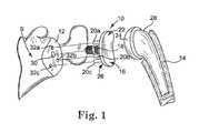
- FIG. 1is an exploded view of a glenoid component positioned between a glenoid and a humeral component in accordance with an embodiment of the present invention.
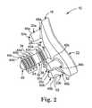
- FIG. 2is a perspective view of the glenoid component in accordance with an embodiment of the present invention.
- FIG. 3is a side view of the glenoid component implanted in the glenoid in accordance with an embodiment of the present invention.
- FIG. 4is a side view of an alternative glenoid component in accordance with an embodiment of the present invention.
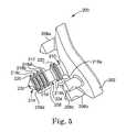
- FIG. 5is a perspective view of an alternative glenoid component in accordance with an embodiment of the present invention.
- FIG. 6is a perspective view of an alternative glenoid component in accordance with an embodiment of the present invention.
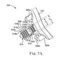
- FIG. 7Ais a perspective view of an alternative glenoid component in accordance with an embodiment of the present invention.
- FIG. 7Bis a side view of the alternative glenoid component of FIG. 7A in accordance with an embodiment of the present invention.
- FIG. 8is a perspective view of an alternative glenoid component in accordance with an embodiment of the present invention.
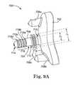
- FIG. 9Ais a perspective view of an alternative glenoid component in accordance with an embodiment of the present invention.
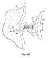
- FIG. 9Bis a side view of a stepped hole configuration in accordance with an embodiment of the present invention.
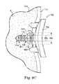
- FIG. 9Cis a side view of the alternative glenoid component of FIG. 9A positioned within the stepped hole configuration of FIG. 9B in accordance with an embodiment of the present invention.
- FIG. 10is an exploded side view an alternative glenoid component in accordance with an embodiment of the present invention.
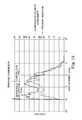
- FIG. 11is a graph of load versus displacement during insertion of the glenoid component in accordance with an embodiment of the present invention.
- FIG. 12is a graph of load versus displacement during removal of the glenoid component in accordance with an embodiment of the present invention.
- FIG. 1shows an exploded view of a glenoid component 10 positioned between a glenoid 12 of a scapula S and a humeral component 14 . While the humeral component 14 illustrated in FIG. 1 is a prosthesis, the present glenoid component 10 can also engage with an anatomical humeral head. Therefore, reference to the humeral component 14 herein should be construed to include an anatomical humeral head.
- the glenoid component 10is attachable to the glenoid 12 and functions as an artificial surface for engagement with the humeral component 14 .
- the glenoid component 10can be secured to the scapula S without the use of bone cement and provides structural resistance from being removed from the scapula S.
- the glenoid component 10includes a head portion 16 , an anchor 18 , a first stabilizing pin 20 a, a second stabilizing pin 20 b and a third stabilizing pin 20 c (collectively referred to as “stabilizing pins 20 ”).
- the head portion 16includes a first articulating surface 22 and a second surface 26 .
- the first articulating surface 22engages the humeral head 24 of the humeral component 14 , which includes a stem 28 implanted in a humerus H, to allow rotation and movement of a shoulder.
- the anchor 18 and stabilizing pins 20 of the glenoid component 10extend from the second surface 26 of the head portion 16 of the glenoid component 10 and secure the glenoid component 10 to the glenoid 12 .
- the glenoid 12 and scapula Sinclude an anchor hole 30 and a plurality of stabilizing holes 32 a, 32 b, 32 c (referred to collectively as “ 32 ”) to accept the anchor 18 and the stabilizing pins 20 , respectively.
- the present glenoid component 10can be implanted without the pre-drilled holes 30 , 32 .
- FIG. 2shows a perspective view of the glenoid component 10 , which functions to provide a replacement surface to articulate with the humeral component 14 .
- the first articulating surface 22 of the head portion 16is concave and configured to engage the humeral head 24 of the humeral component 14 .
- the first articulating surface 22is thus formed to accept at least a portion of the humeral head 24 within the concavity of the first articulating surface 22 .
- the second surface 26 of the head portion 16is preferably configured with the same shape as the glenoid 12 of the scapula S, which is usually convex.
- the anchor 18extends substantially perpendicularly from the second surface 26 of the head portion 16 and secures the glenoid component 10 to the glenoid 12 . In other embodiments, the anchor 18 may extend at various other angles relative to the second surface 26 of the head portion 16 .
- the anchor 18is preferably positioned substantially at the center of the second surface 26 of the head portion 16 and is in the form of a cylindrical shaft 34 having a proximal end 36 , a middle section 38 and a distal end 40 .
- the shaft 34is attached to the head portion 16 at the proximal end 36 and tapers at the distal end 40 to facilitate insertion of the anchor 18 into the anchor hole 30 of the glenoid 12 .
- the distal end 40 of the anchor 18includes a conical tip, or other shape that facilitates insertion into the glenoid 12 , with or without the pre-drilled hole 30 .
- the anchor 18can have a tapered or stepped structure.
- the anchor 18has a substantially consistent diameter.
- Distal fins 44extend radially outward from the distal end 40 of the shaft 34 and proximal fins 42 extend radially outward from the proximal end 36 of the shaft 34 .
- the set of proximal fins 42includes a first proximal fin 42 a and a second proximal fin 42 b.
- the set of distal fins 44includes a first distal fin 44 a, a second distal fin 44 b, a third distal fin 44 c and a fourth distal fin 44 c.
- the sets of distal fins 44 and proximal fins 42are spaced from each other by the middle section 38 of the shaft 34 .
- the sets of proximal and distal fins 42 , 44extend the full length of the shaft 34 without being separated by the middle section 38 .
- Both sets of proximal and distal fins 42 , 44are flexible and are configured to bend or deform when force is exerted against them. Deformation of the proximal and distal fins 42 a, 42 b , 44 a, 44 b, 44 c, 44 d can be plastic or elastic.
- the proximal and distal fins 42 a, 42 b, 44 a, 44 b, 44 c, 44 ddeform plastically upon insertion into the glenoid 12 and retain a generally curved configuration, such as illustrated in FIG. 3 .
- the proximal and distal fins 42 a, 42 b, 44 a, 44 b, 44 c, 44 dreturn to their un-deformed configuration after implantation.
- the proximal and distal fins 42 a, 42 b, 44 a, 44 b, 44 c, 44 dhave substantially the same diameter. Consequently, the proximal and distal fins 42 a, 42 b, 44 a , 44 b, 44 c, 44 d are co-axial with each other and the outside edges are aligned.
- FIG. 2depicts the set of proximal fins 42 as including two fins 42 a, 42 b and the set of distal fins 44 as including four fins 44 a, 44 b, 44 c, 44 d, the sets of proximal fins and distal fins 42 , 44 may include any number of fins.
- the shaft 34 and the proximal and distal fins 42 a, 42 b, 44 a, 44 b, 44 c , 44 d of the anchor 18are integrally formed with the head portion 16 .
- the glenoid component 10can be molded as a single unitary structure or machined from a monolithic piece of material.
- the shaft 34 and the proximal and distal fins 42 a, 42 b, 44 a, 44 b , 44 c, 44 dare separate components (See e.g., FIG. 10 ).
- the proximal and distal fins 42 a, 42 b, 44 a, 44 b, 44 c, 44 dare molded from a first material while the head portion 16 is molded from a second material.
- the first materialpreferably has a higher stiffness than the second material.
- the glenoid component 10 of the present applicationcan be manufactured from a variety of materials, such as for example polyethylene or ultra-high molecular weight polyethylene (“UHMWPE”), such as disclosed in U.S. Pat. No. 6,911,047, the disclosure of which is incorporated herein by reference.
- UHMWPEultra-high molecular weight polyethylene
- the stabilizing pins 20prevent the glenoid component 10 from moving relative to the glenoid 12 once the glenoid component 10 is implanted in the glenoid 12 and the scapula S.
- the stabilizing pins 20preferably extend substantially perpendicularly from the second surface 26 of the head portion 16 and are positioned around the anchor 18 .
- Each of the stabilizing pins 20 a, 20 b , 20 cincludes a body 46 a, 46 b, 46 c (collectively referred to as “bodies 46 ”), respectively, having a proximal end 48 a, 48 b, 48 c (collectively referred to as “proximal ends 48 ”), respectively, and a distal end 50 a, 50 b, 50 c (collectively referred to as “distal ends 50 ”), respectively.
- Each of the bodies 46 of the stabilizing pins 20is attached at its proximal end 48 to the head portion 16 of the glenoid component 10 .
- the stabilizing pins 20optionally include an indent or series of indents 52 to accept and lock in bone cement, maintaining the stabilizing pins 20 in position.
- the stabilizing pins 20are preferably shorter than the anchor 18 and in one embodiment extend only slightly past the set of proximal fins 42 of the anchor 18 . Similar to the distal end 40 of the anchor 18 , the distal ends 50 of the stabilizing pins 20 are also tapered to facilitate insertion of the stabilizing pins 20 into the stabilizing holes 32 of the glenoid 12 . In one embodiment, the distal ends 50 of the stabilizing pins 20 have a conical tip, or other shape that facilitates insertion into the glenoid 12 , with or without pre-drilled hole 32 .
- the stabilizing pins 20may be arranged in any configuration on the second side 26 of the head portion 16 around the anchor 18 .
- the stabilizing pins 20are positioned such that the first stabilizing pin 20 a is positioned farther from the anchor 18 than the second and third stabilizing pins 20 b, 20 c.
- the stabilizing pins 20are positioned around the anchor 18 along a periphery of the head portion 16 substantially equidistant from the anchor 18 and each adjacent stabilizing pin 20 a, 20 b, 20 c.
- FIG. 2depicts the glenoid component 10 as including three stabilizing pins 20 , the glenoid component 10 may include any number of stabilizing pins, including zero, without departing from the intended scope of the present invention.
- any means for preventing rotation of the glenoid component 10 relative to the glenoid 12may be used.
- the glenoid 12may be milled in an oval shape and the glenoid component 10 may be key implanted into the bone.
- FIG. 3shows a side view of the glenoid component 10 implanted through the glenoid 12 and into the scapula S.
- the anchor hole 30 and the plurality of stabilizing holes 32are preferably first drilled or otherwise formed in the glenoid 12 .
- the anchor hole 30is preferably sized to have a diameter D AH slightly larger than a diameter D S of the shaft 34 of the anchor 18 but smaller than a diameter D F of the distal and proximal fins 42 a, 42 b, 44 a, 44 b, 44 c, 44 d of the anchor 18 .
- proximal and distal fins 42 a, 42 b, 44 a, 44 b, 44 c, 44 dare flexible, even though the diameters D F of the proximal and distal fins 42 a, 42 b, 44 a, 44 b, 44 c, 44 d are larger than the diameter D AH of the anchor hole 30 , the proximal and distal fins 42 a, 42 b, 44 a, 44 b, 44 c, 44 d can pass through the anchor hole 30 by exerting an extra amount of force on the glenoid component 10 and causing the proximal and distal fins 42 a, 42 b, 44 a, 44 b, 44 c, 44 d to deform.
- the stabilizing holes 32are drilled around the anchor hole 30 and are sized to accept the stabilizing pins 20 .
- the stabilizing pins 20may be press fit or interference fit into the stabilizing holes 32 .
- bone cementmay also be utilized to help maintain the stabilizing pins 20 within the stabilizing holes 32 . If it is desired to use bone cement to aid in securing the glenoid component 10 to the glenoid 12 , the bone cement can be applied at the indents 52 of the bodies 46 of the stabilizing pins 20 to increase the area of contact between the stabilizing pins 20 and the bone cement in order to increase the bond to secure the stabilizing pins 20 within the stabilizing holes 32 .
- the anchor hole 30 and the stabilizing holes 32are drilled such that when the glenoid component 10 is positioned with respect to the glenoid 12 , the anchor 18 is aligned with the anchor hole 30 and the stabilizing pins 20 are aligned with the stabilizing holes 32 .
- a drill guide or patternmay be used to properly position and align the anchor hole 30 and the stabilizing holes 32 in the glenoid 12 to correspond with the positions and alignments of the anchor 18 and stabilizing pins 20 of the glenoid component 10 , respectively.
- the glenoid component 10is positioned in front of the glenoid 12 such that the anchor 18 and stabilizing pins 20 of the glenoid component 10 are aligned with the anchor hole 30 and the stabilizing holes 32 , respectively, of the glenoid 12 .
- the conical tip at the distal end 40 of the shaft 34 of the glenoid component 10first enters the anchor hole 30 .
- each of the distal fins 44 a, 44 b, 44 c, 44 ddeforms sequentially in order to pass through the anchor hole 30 .
- the set of distal fins 44are advanced past the cortical bone 12 a , they engage with the softer cancellous bone 12 b.
- the distance “d” between the first proximal fin 42 a and the second surface 26 of the head portion 16corresponds generally to the thickness of the cortical bone 12 a.
- the distance “d”is generally between about 1 to about 4 millimeters, and preferably between about 2 to about 3 millimeters. In the embodiment of FIG. 10 , the distance “d” is adjustable by substituting a different spacer 306 .
- the proximal fins 42 a, 42 bprovide resistance against the smaller diameter D AH of the anchor hole 30 so enough force must be exerted in order to engage the proximal fins 42 a, 42 b with the cortical bone 12 a.
- the set of proximal fins 42pass through the cortical bone 12 a and into the cancellous bone 12 b of the scapula S.
- the first proximal fin 42 ais positioned in the cortical bone 12 a and the second proximal fin 42 b is positioned adjacent to the cortical bone 12 a.
- the stabilizing pins 20In order to fully insert the anchor 18 through the anchor hole 30 , the stabilizing pins 20 must be aligned with stabilizing holes 32 such that the stabilizing pins 20 engage with respective stabilizing holes 32 . Thus, as the anchor 18 is advanced into the anchor hole 30 , the stabilizing pins 20 are simultaneously advanced into the stabilizing holes 32 . Because the stabilizing pins 20 have a substantially consistent diameter and the stabilizing holes 32 are sized to accept the stabilizing pins 20 , extra force is not required to advance the stabilizing pins 20 into the scapula S.
- the glenoid component 10is advanced into the scapula S until the second surface 26 of the head portion 16 abuts the glenoid 12 and the anchor 18 and stabilizing pins 20 are fully inserted into the scapula S.
- the stabilizing pins 20prevent rotation or movement of the glenoid component 10 relative to the glenoid 12 .
- the proximal and distal fins 42 a, 42 b, 44 a, 44 b, 44 c, 44 dare bent towards the glenoid 12 , securing the glenoid component 10 to the scapula S.
- the anchor 18 of the glenoid component 10is positioned in the scapula S such that the sets of distal and proximal fins 42 , 44 are embedded in the cancellous bone 12 b, which has low density and strength and fills the inner cavity of the scapula S.
- the set of proximal fins 42is located proximate the second surface 26 of the head portion 16 , the set of proximal fins 42 is located adjacent and proximate the cortical bone 12 a, which is dense and forms the surface of the scapula S.
- the first proximal fin 42 aabuts the cortical bone 12 a , providing resistance to prevent the set of proximal fins 42 from passing through the anchor hole 30 and removing the anchor 18 from the scapula S.
- the proximal fins 42 a, 42 balso function to stabilize the shaft 34 and prevent the shaft 34 from bending when side loaded.
- the glenoid component 10provides increased resistance to removal from the scapula S compared to a glenoid component that does not include a set of proximal fins.
- tissuewill grow into the spaces between the fins 42 a, 42 b, 44 a, 44 b, 44 c, 44 d and provide further resistance to pulling out the anchor 18 from the anchor hole 30 .
- the combination of the configuration of the sets of proximal and distal fins 42 , 44 within the scapula S and the tissue that grows around the fins 42 a, 42 b, 44 a, 44 b, 44 c, 44 deliminates or reduces the need to use bone cement or other adhesive means to secure the glenoid component 10 to the glenoid 12 .
- the indents 52 in the bodies 46 of the stabilizing pins 20also provide an area for tissue to grow, further increasing the force required to remove the glenoid component 10 from the scapula S.
- the first articulating surface 22 of the head portion 16 of the glenoid component 10acts as an articulating or bearing surface for engaging the humeral head 24 of the humeral component 14 .
- the glenoid component 10thus functions as a replacement for the natural glenoid of the scapula S, allowing the glenoid component 10 , the glenoid 12 and the humeral component 14 to interact similarly to a natural shoulder socket.
- FIG. 4shows a side view of an alternative glenoid component 100 .
- the glenoid component 100functions substantially similarly to the glenoid component 10 of FIGS. 1 and 2 and includes a head portion 102 , an anchor 104 and a plurality of stabilizing pins 106 a, 106 b (not shown), 106 c .
- the anchor 104includes a shaft 108 having a proximal end 110 , a middle section 112 and a distal end 114 .
- a set of proximal fins 116extends radially from the proximal end 110 of the shaft 108 and a set of distal fins 118 extends radially from the distal end 114 of the shaft 108 .
- the sets of proximal and distal fins 116 , 118are optionally separated by the middle section 112 of the shaft 108 .
- the anchor 104 of the glenoid component 100is substantially similar to the anchor 18 of the glenoid component 10 of FIGS. 1 and 2 except that each of the first proximal fin 116 a and the first, second and third distal fins 118 a, 118 b and 118 c includes a rib feature 120 to create preferential deformation of the fins 116 a, 118 a, 118 b and 118 c.
- the rib features 120function to transfer load between the proximal fins 116 a, 116 b, and between the distal fins 118 a, 118 b, 118 c , 118 d, to reduce fin deformation in response to a removal force 121 .
- the rib feature 120 of the first proximal distal fin 116 aabuts the second proximal fin 116 b, reducing deformation arising from the removal force 121 .
- the rib feature 120 of the first distal fin 118 aabuts the second distal fin 118 b
- the rib feature 120 of the second distal fin 118 babuts the third distal fin 118 c
- the rib feature 120 of the third distal fin 118 cabuts the fourth proximal fin 118 d , reducing deformation of the respective first, second and third distal fins 118 a, 118 b, 118 c in response to the removal force 121 .
- the fins 116 a, 118 a, 118 b, 118 care substantially uni-directionally deformable.
- “uni-directionally deformable” or “uni-directional deformation”refer to a structure that deforms in a first direction, but resists deformation in an opposite second direction.
- FIG. 5shows a perspective view of an alternative glenoid component 200 .
- the glenoid component 200functions substantially similarly to the glenoid component 10 of FIGS. 1 and 2 and includes a head portion 202 , an anchor 204 and a plurality of stabilizing pins 206 a, 206 b, 206 c .
- the anchor 204includes a shaft 208 having a proximal end 210 , a middle section 212 and a distal end 214 .
- a set of proximal fins 216extends radially from the proximal end 210 of the shaft 208 and a set of distal fins 218 extends radially from the distal end 214 of the shaft 208 .
- the proximal and distal fins 216 , 218are optionally separated by the middle section 212 of the shaft 208 .
- the anchor 204 of the glenoid component 200is substantially similar to the anchor 18 of the glenoid component 10 of FIGS. 1 and 2 except that each of the proximal and distal fins 216 a , 216 b, 218 a, 218 b, 218 c, 218 d includes one or more cut-outs 220 .
- the amount of force required to insert the glenoid component 10is also reduced.
- radial cut-outs 220are machined through all of the proximal and distal fins 216 a, 216 b, 218 a, 218 b, 218 c, 218 d in order to reduce the surface area.
- FIG. 5depicts the cut-outs 220 as being positioned substantially symmetrically around the anchor 204 , the cut-outs 220 may be positioned anywhere around the anchor 204 without departing from the intended scope of the invention.
- FIG. 6shows a perspective view of an alternative glenoid component 400 .
- the glenoid component 400functions substantially similarly to the glenoid component 10 of FIGS. 1 and 2 and includes a head portion 402 , an anchor 404 and a plurality of stabilizing pins 406 a, 406 b, 406 c .
- the anchor 404includes a shaft 408 having a proximal end 410 , a middle section 412 and a distal end 414 .
- a set of proximal fins 416extends radially from the proximal end 410 of the shaft 408 and a set of distal fins 418 extends radially from the distal end 414 of the shaft 408 .
- the sets of distal and proximal fins 416 , 418are optionally separated by the middle section 412 of the shaft 108 .
- the anchor 404 of the glenoid component 400is substantially similar to the anchor 18 of the glenoid component 10 of FIGS. 1 and 2 except that the proximal end 410 of the shaft 408 of the anchor 404 includes a stabilizing boss 420 .
- the stabilizing boss 420has a diameter D B that is larger than the diameter D S of the shaft 408 but smaller than the diameters D F of the sets of proximal and distal fins 416 , 418 .
- the stabilizing boss 420functions to aid in stabilizing the shaft 408 in a radial load condition.
- the stabilizing boss 420has a diameter substantially equal to the diameter of the anchor hole 30 D AH ( FIG. 3 ) to help prevent the shaft 408 from bending when side loaded.
- FIGS. 7A and 7Bshow a perspective view and a side view, respectively, of an alternative glenoid component 500 .
- the glenoid component 500functions substantially similarly to the glenoid component 10 of FIGS. 1 and 2 and includes a head portion 502 , an anchor 504 and a plurality of stabilizing pins 506 a, 506 b, 506 c.
- the anchor 504includes a shaft 508 having a proximal end 510 , a middle section 512 and a distal end 514 .
- a set of proximal fins 516extends radially from the proximal end 510 of the shaft 508 and a set of distal fins 518 extends radially from the distal end 514 of the shaft 508 .
- the proximal and distal fins 516 , 518are optionally separated by the middle section 512 of the shaft 508 .
- the anchor 504 of the glenoid component 500is substantially similar to the anchor 18 of the glenoid component 10 of FIGS. 1 and 2 except that the diameters of the proximal fins 516 a , 516 b, 516 c are not the same.
- the first and second proximal fins 516 b, 516 bhave a smaller diameter than the diameter D F of the third proximal fin 516 c.
- the smaller diameters of the first and second proximal fins 516 a, 516 bfunction to stabilize the shaft 508 of the anchor 504 and to prevent the shaft 508 from bending from side loading.
- the diameters of the first and second proximal fins 516 a, 516 bare substantially equal to the diameter of the anchor hole 30 D AH .
- FIG. 8shows a perspective view of an alternative glenoid component 600 .
- the glenoid component 600functions substantially similarly to the glenoid component 10 of FIGS. 1 and 2 and includes a head portion 602 , an anchor 604 and a plurality of stabilizing pins 606 a, 606 b, 606 c .
- the anchor 604includes a shaft 608 having a proximal end 610 , a middle section 612 and a distal end 614 .
- a set of proximal fins 616extends radially from the proximal end 610 of the shaft 608 .
- the anchor 604 of the glenoid component 600is substantially similar to the anchor 18 of the glenoid component 10 of FIGS. 1 and 2 except that the anchor 604 does not include a set of distal fins.
- the middle section 612 and the distal end 614 of the shaft 608are smooth with no radial extensions.
- the embodiment shown in FIG. 8illustrates that distal fins are not required to fixate the glenoid component 600 to the glenoid 12 ( FIG. 1 ).
- initial fixationcan still be achieved using only the set of proximal fins 616 .
- FIG. 9Ashows a perspective view of an alternative glenoid component 700 .
- the glenoid component 700functions substantially similarly to the glenoid component 10 of FIGS. 1 and 2 and includes a head portion 702 , an anchor 704 and a plurality of stabilizing pins 706 a, 706 b, 706 c .
- the anchor 704has a diameter D A and includes a shaft 708 having a proximal end 710 , a middle section 712 and a distal end 714 .
- a set of proximal fins 716extends radially from the proximal end 710 of the shaft 708 and has a diameter D F .
- the anchor 704 of the glenoid component 700is substantially similar to the anchor 18 of the glenoid component 10 of FIGS. 1 and 2 except that rather than having a set of distal fins extending radially from the distal end 714 of the shaft 708 , the distal end 714 includes a plurality of grooves 718 a, 718 b, 718 c, 718 d (collectively referred to as “grooves 718 ”) machined into the shaft 708 .
- the grooves 718may be machined into the distal end 714 of the shaft 708 by any means known in the art. In one embodiment, the grooves 718 are machined into the shaft 708 by step drilling. Similar to the glenoid component 600 shown in FIG.
- initial fixation of the anchor 704 of the glenoid component 700can still be achieved using just the set of proximal fins 716 .
- long term fixationis achieved through bone in-growth into the grooves 718 .
- FIG. 9depicts the distal end 714 of the shaft 708 as including four grooves 718 , the distal end 714 of the shaft 708 may include any number of grooves.
- FIG. 9Bshows a side view of a stepped hole configuration 800 created through the cortical bone 12 a and within the cancellous bone 12 b.
- FIG. 9Cshows a side view of the anchor 704 of the glenoid component 700 positioned within the stepped hole configuration 800 .
- the stepped hole 800is sized to receive the anchor 704 of the glenoid component 700 and initially reduce the amount of force required to insert the anchor 704 of the glenoid component 700 into the scapula S.
- the stepped hole 800includes a proximal portion 802 having a first diameter SH 1 and a distal portion 804 having a second diameter SH 2 bone 12 b.
- the proximal portion 802is located through the cortical bone 12 a and the cancellous bone 12 b and the distal portion 804 is located within the cancellous bone 12 b.
- the first diameter SH 1is greater than the second diameter SH 2 and slightly smaller than the diameter D F ( FIG. 9B ) of the set of proximal fins 716 .
- the second diameter SH 2is substantially the same size as the diameter D A of the anchor 704 , allowing easily insertion of the distal end 714 of the anchor into the stepped hole 800 .
- the diameter D F of the set of proximal fins 716is greater than the first diameter SH 1 of the stepped hole 800 , as the proximal end 710 of the anchor 704 is inserted into the stepped hole 800 , there is “lock-up” of the set of proximal fins 716 under the cortical bone 12 a.
- the relative sizes of the second diameter SH 2 of the stepped hole 800 and the anchor D Aallows for bone ingrowth into the recessed grooves 718 at the distal end 714 of the shaft 708 .
- the stepped hole 800is discussed with relation to glenoid component 700 , the stepped hole 800 may be used with other glenoid components in which the proximal end of the anchor has a greater diameter than the distal end of the anchor.
- the stepped hole configuration 800may also be used with the glenoid component 600 shown in FIG. 8 .
- the step hole 800is formed using a step drill.
- FIG. 10shows an exploded side view of an alternative glenoid component 300 .
- the glenoid component 300may have a modular design.
- the glenoid component 300functions substantially similarly to the glenoid component 10 of FIGS. 1 and 2 and includes a head portion 302 , an anchor portion 304 and a plurality of stabilizing pins 306 a, 306 b (not shown), 306 c.
- the head portion 302is preferably a single piece of material, while the anchor portion 304 is formed of a plurality of modular pieces.
- the anchor portion 304includes a first spacer 308 , a first proximal fin 310 a, a second proximal fin 310 b, a second spacer 312 and a set of distal fins 314 .
- the first spacer 308sets an offset between a second surface 326 of the head portion 302 and the first proximal fin 310 a corresponding generally to a thickness of the cortical bone 12 a ( FIG. 3 ).
- Each of the modular pieces 308 , 310 a, 310 b, 312 , 314 of the anchor portion 304includes a bore 316 running through the center of the pieces 308 , 310 a, 310 b, 312 , 314 such that they can be maintained together and fixed to the head portion 302 by a screw 318 .
- FIG. 10shows the glenoid component 300 as including the modular pieces 308 , 310 a, 310 b, 312 , 314
- the glenoid component 300may include any number of modular pieces without departing from the intended scope of the present invention.
- the glenoid component 300may include additional spacers to accommodate a patient with larger proportions or may include only one spacer to accommodate a patient with smaller proportions.
- Various spacersmay also be provided having varying thicknesses.
- additional finsmay be included adjacent the set of distal fins 314 or one of the proximal fins 310 a, 310 b.
- FIG. 10is particularly well suited for building the glenoid component 300 from multiple materials.
- the head portion 302can be made from a first material and one or more of the other pieces 308 , 310 a, 310 b, 312 , 314 can be made from one or more second materials. Forming the pieces 308 , 310 a, 310 b, 312 , 314 separately also facilitates formation of various structures to achieve uni-lateral deformation.
- the individual structural features of each of the embodimentsmay be incorporated into any glenoid component.
- the glenoid component 700 ( FIG. 9 ) having the distal grooves 718may also include the stabilizing boss 420 ( FIG. 6 ) or the proximal fins 516 a and 516 b having decreased diameters ( FIG. 7 ) for increased stability.
- FIG. 11illustrates the load versus displacement of a glenoid component of the present invention and the load versus displacement of a comparative glenoid component during insertion into a foam structure designed to exhibit similar density properties of a scapula.
- the foam structureincluded an anchor hole for accepting an anchor of the glenoid component of the present invention and an anchor of the comparative glenoid component.
- the glenoid component of the present inventionincluded an anchor having a set of four distal fins extending from a distal end of the anchor and a set of two proximal fins extending from a proximal end of the anchor.
- the set of distal fins and the set of proximal finsare separated by a middle section of the anchor, such as illustrated in FIG. 2 .
- the set of proximal finswere offset from a rear surface of the head portion by about 2.5 millimeters.
- the comparative glenoid componentwas substantially similar to the glenoid component of the present invention except that the comparative glenoid component did not include a set of proximal fins positioned to engage with the cortical bone.
- the comparative glenoid componentincluded only a set of four distal fins.
- the force required to advance the distal end of the glenoid component of the present invention and the distal end of the comparative glenoid component into the foam structurewas comparable.
- the distal fins on both glenoid componentscontacted the anchor hole of the foam structure.
- the amount of force that was applied to the glenoid componentincreased, creating a first spike, a second spike and a third spike corresponding to the location of the first, second, and third distal fins along the distal end of the anchor.
- the amount of force required to advance the anchor through the anchor holeincreased in response to the first and second proximal fins engaging the anchor hole.
- the amount of force required to advance the proximal fins into the foam structureincreased sharply as the first proximal fin and then the second proximal fin contacted the anchor hole, spiking to a required load of about 44.5 pounds and 39.5 pounds, respectively.
- the comparative glenoid componentdid not require additional force to advance the proximal end of the anchor into the anchor hole. Rather, the amount of force required to advance the comparative glenoid component into the foam structure steadily decreased to about 10 or about 11 pounds.
- the glenoid component of the present inventionrequired about 75% more force to insert the proximal end of the anchor through the anchor hole than required to insert the proximal end of the anchor of the comparative glenoid component through the anchor hole.
- FIG. 12illustrates the load versus displacement of the glenoid component of the present invention and the load versus displacement of the comparative glenoid component during removal from the foam structure.
- the initial force required to pull the glenoid component of the present invention out from the foam structurespiked to about 39 pounds in the first millimeter of displacement, followed immediately by a spike of about 43.5 pounds at about 2 millimeters of displacement.
- a force of about 39 poundswas required to pull the first proximal fin through the anchor hole and a force of about 43.5 pounds was required to pull the second proximal fin through the anchor hole.
- the initial force required to move the comparative glenoid component relative to the foam structureincreased more gradually, and only to an initial force of about 24 pounds within about 2 millimeters of displacement. It was not until the comparative glenoid component was displaced about 7.5 millimeters that the first distal fin engaged the anchor hole and increased the removal force to about 34 pounds.
- the glenoid component of the present inventionprovided a force about 71.5% greater than the comparative glenoid component, over less than half the displacement. As a result, the present glenoid component provided a significantly greater resistance to initial displacement than the comparative glenoid component.
Landscapes
- Health & Medical Sciences (AREA)
- Orthopedic Medicine & Surgery (AREA)
- Cardiology (AREA)
- Oral & Maxillofacial Surgery (AREA)
- Transplantation (AREA)
- Engineering & Computer Science (AREA)
- Biomedical Technology (AREA)
- Heart & Thoracic Surgery (AREA)
- Vascular Medicine (AREA)
- Life Sciences & Earth Sciences (AREA)
- Animal Behavior & Ethology (AREA)
- General Health & Medical Sciences (AREA)
- Public Health (AREA)
- Veterinary Medicine (AREA)
- Prostheses (AREA)
Abstract
Description
Claims (11)
Priority Applications (7)
| Application Number | Priority Date | Filing Date | Title |
|---|---|---|---|
| US15/379,359US10524922B2 (en) | 2009-03-05 | 2016-12-14 | Glenoid implant anchor post |
| US16/700,267US11160662B2 (en) | 2009-03-05 | 2019-12-02 | Glenoid implant anchor post |
| US17/488,749US11633286B2 (en) | 2009-03-05 | 2021-09-29 | Glenoid implant anchor post |
| US17/586,126US11344423B1 (en) | 2009-03-05 | 2022-01-27 | Glenoid implant anchor post |
| US17/659,588US11865012B2 (en) | 2009-03-05 | 2022-04-18 | Glenoid implant anchor post |
| US18/519,178US12245947B2 (en) | 2009-03-05 | 2023-11-27 | Glenoid implant anchor post |
| US18/934,388US20250057661A1 (en) | 2009-03-05 | 2024-11-01 | Method of implanting glenoid anchor |
Applications Claiming Priority (2)
| Application Number | Priority Date | Filing Date | Title |
|---|---|---|---|
| US12/398,750US9545311B2 (en) | 2009-03-05 | 2009-03-05 | Glenoid implant anchor post |
| US15/379,359US10524922B2 (en) | 2009-03-05 | 2016-12-14 | Glenoid implant anchor post |
Related Parent Applications (1)
| Application Number | Title | Priority Date | Filing Date |
|---|---|---|---|
| US12/398,750DivisionUS9545311B2 (en) | 2009-03-05 | 2009-03-05 | Glenoid implant anchor post |
Related Child Applications (1)
| Application Number | Title | Priority Date | Filing Date |
|---|---|---|---|
| US16/700,267ContinuationUS11160662B2 (en) | 2009-03-05 | 2019-12-02 | Glenoid implant anchor post |
Publications (2)
| Publication Number | Publication Date |
|---|---|
| US20170095340A1 US20170095340A1 (en) | 2017-04-06 |
| US10524922B2true US10524922B2 (en) | 2020-01-07 |
Family
ID=42412042
Family Applications (8)
| Application Number | Title | Priority Date | Filing Date |
|---|---|---|---|
| US12/398,750Active2032-04-22US9545311B2 (en) | 2009-03-05 | 2009-03-05 | Glenoid implant anchor post |
| US15/379,359ActiveUS10524922B2 (en) | 2009-03-05 | 2016-12-14 | Glenoid implant anchor post |
| US16/700,267Active2029-06-03US11160662B2 (en) | 2009-03-05 | 2019-12-02 | Glenoid implant anchor post |
| US17/488,749Active2029-05-08US11633286B2 (en) | 2009-03-05 | 2021-09-29 | Glenoid implant anchor post |
| US17/586,126ActiveUS11344423B1 (en) | 2009-03-05 | 2022-01-27 | Glenoid implant anchor post |
| US17/659,588Active2029-05-31US11865012B2 (en) | 2009-03-05 | 2022-04-18 | Glenoid implant anchor post |
| US18/519,178ActiveUS12245947B2 (en) | 2009-03-05 | 2023-11-27 | Glenoid implant anchor post |
| US18/934,388PendingUS20250057661A1 (en) | 2009-03-05 | 2024-11-01 | Method of implanting glenoid anchor |
Family Applications Before (1)
| Application Number | Title | Priority Date | Filing Date |
|---|---|---|---|
| US12/398,750Active2032-04-22US9545311B2 (en) | 2009-03-05 | 2009-03-05 | Glenoid implant anchor post |
Family Applications After (6)
| Application Number | Title | Priority Date | Filing Date |
|---|---|---|---|
| US16/700,267Active2029-06-03US11160662B2 (en) | 2009-03-05 | 2019-12-02 | Glenoid implant anchor post |
| US17/488,749Active2029-05-08US11633286B2 (en) | 2009-03-05 | 2021-09-29 | Glenoid implant anchor post |
| US17/586,126ActiveUS11344423B1 (en) | 2009-03-05 | 2022-01-27 | Glenoid implant anchor post |
| US17/659,588Active2029-05-31US11865012B2 (en) | 2009-03-05 | 2022-04-18 | Glenoid implant anchor post |
| US18/519,178ActiveUS12245947B2 (en) | 2009-03-05 | 2023-11-27 | Glenoid implant anchor post |
| US18/934,388PendingUS20250057661A1 (en) | 2009-03-05 | 2024-11-01 | Method of implanting glenoid anchor |
Country Status (2)
| Country | Link |
|---|---|
| US (8) | US9545311B2 (en) |
| EP (1) | EP2238949B1 (en) |
Cited By (8)
| Publication number | Priority date | Publication date | Assignee | Title |
|---|---|---|---|---|
| US20190231545A1 (en)* | 2015-08-10 | 2019-08-01 | Catalyst Orthoscience Inc. | Arthroplasty prostheses with multi-axis fixation |
| US10918492B2 (en) | 2011-02-01 | 2021-02-16 | Tornier Sas | Glenoid implant for a shoulder prosthesis, and surgical kit |
| US10973646B2 (en) | 2013-03-11 | 2021-04-13 | Catalyst Orthoscience Inc. | Stabilized drill guide |
| US11007063B2 (en) | 2013-03-11 | 2021-05-18 | Catalyst Orthoscience Inc. | Offset reamers |
| US11033399B2 (en) | 2016-02-28 | 2021-06-15 | Integrated Shoulder Collaboration, Inc. | Shoulder arthroplasty implant system |
| US11160661B2 (en) | 2009-12-14 | 2021-11-02 | Tornier Sas | Shoulder prosthesis glenoid component |
| US11160662B2 (en) | 2009-03-05 | 2021-11-02 | Howmedica Osteonics Corp. | Glenoid implant anchor post |
| US11833055B2 (en) | 2016-02-28 | 2023-12-05 | Integrated Shoulder Collaboration, Inc. | Shoulder arthroplasty implant system |
Families Citing this family (52)
| Publication number | Priority date | Publication date | Assignee | Title |
|---|---|---|---|---|
| US7892288B2 (en) | 2001-08-27 | 2011-02-22 | Zimmer Technology, Inc. | Femoral augments for use with knee joint prosthesis |
| US20030065397A1 (en) | 2001-08-27 | 2003-04-03 | Hanssen Arlen D. | Prosthetic implant support structure |
| US8778028B2 (en) | 2005-02-25 | 2014-07-15 | Shoulder Innovations, Inc. | Methods and devices for less invasive glenoid replacement |
| US20230080207A1 (en) | 2005-02-25 | 2023-03-16 | Shoulder Innovations, Inc. | Methods and devices for less invasive glenoid replacement |
| US8257363B2 (en)* | 2007-10-12 | 2012-09-04 | Howmedica Osteonics Corp. | Expandable reverse shoulder trial |
| EP2575689A2 (en) | 2010-05-26 | 2013-04-10 | Topsfield Medical GmbH | Implantable prostheses |
| FR2967046A1 (en) | 2010-11-10 | 2012-05-11 | Tornier Sa | ORTHOPEDIC BONE PREPARATION MACHINE, ESPECIALLY GLENOIDIAN PREPARATION |
| WO2012125704A2 (en)* | 2011-03-14 | 2012-09-20 | Topsfield Medical Gmbh | Implantable glenoid prostheses |
| USD653339S1 (en) | 2011-04-18 | 2012-01-31 | Ascension Orthopedics, Inc. | Double cannulated osteotome |
| US9421106B2 (en) | 2011-12-07 | 2016-08-23 | Howmedica Osteonics Corp. | Reverse shoulder baseplate with alignment guide for glenosphere |
| US9439768B2 (en) | 2011-12-08 | 2016-09-13 | Imds Llc | Glenoid vault fixation |
| US9414927B2 (en) | 2011-12-08 | 2016-08-16 | Imds Llc | Shoulder arthroplasty |
| US8663334B2 (en) | 2012-05-31 | 2014-03-04 | Howmedica Osteonics Corp. | Lateral entry insert for cup trial |
| US8906102B2 (en) | 2012-05-31 | 2014-12-09 | Howmedica Osteonics Corp. | Lateral entry insert for cup trial |
| US20140005789A1 (en)* | 2012-06-28 | 2014-01-02 | Depuy Products, Inc. | Modified Glenoid Components and Methods of Installing Same |
| US8876907B2 (en)* | 2012-07-26 | 2014-11-04 | Howmedica Osteonics Corp. | Cement pressurizing glenoid |
| US20150223941A1 (en)* | 2012-08-27 | 2015-08-13 | Conformis, Inc. | Methods, Devices and Techniques for Improved Placement and Fixation of Shoulder Implant Components |
| US9788957B2 (en) | 2012-12-07 | 2017-10-17 | Cleveland Clinic Foundation | Glenoid vault fixation |
| USD730522S1 (en) | 2013-03-11 | 2015-05-26 | Catalyst Orthopaedics Llc | Implant |
| US9814471B2 (en) | 2013-03-11 | 2017-11-14 | Catalyst Orthoscience Inc. | Glenoid arthroplasty and offset reamers |
| US9814588B2 (en)* | 2015-08-10 | 2017-11-14 | Catalyst Orthoscience Inc. | Glenoid arthroplasty with multi-directional fixation |
| WO2015066608A1 (en)* | 2013-11-04 | 2015-05-07 | Boulris Craig | Shoulder replacement with enhanced glenoid fixation |
| US9962266B2 (en) | 2015-09-11 | 2018-05-08 | Deltoid, Llc | Arthroplasty components |
| US10433969B2 (en) | 2013-12-30 | 2019-10-08 | United Orthopedic Corp. | Arthroplasty implants and methods for orienting joint prosthesis |
| WO2015103090A1 (en) | 2014-01-03 | 2015-07-09 | Tornier, Inc. | Reverse shoulder systems |
| US20150272741A1 (en)* | 2014-03-26 | 2015-10-01 | Biomet Manufacturing, Llc | Press-fit glenoid with peripheral compression pegs |
| FR3021864B1 (en)* | 2014-06-06 | 2019-10-25 | In2Bones | SURGICAL IMPLANT, IMPLEMENT TOOL, SURGICAL KIT AND METHOD FOR MANUFACTURING THE SAME |
| US10028838B2 (en) | 2014-06-30 | 2018-07-24 | Tornier, Inc. | Augmented glenoid components and devices for implanting the same |
| US11234826B2 (en)* | 2014-06-30 | 2022-02-01 | Howmedica Osteonics Corp. | Augmented glenoid components and devices for implanting the same |
| US9844440B2 (en) | 2014-08-14 | 2017-12-19 | Biomet Manufacturing, Llc | Glenoid implant |
| US10492926B1 (en) | 2014-09-04 | 2019-12-03 | Shoulder Innovations, Inc. | Alignment guide for humeral or femoral stem replacement prostheses |
| WO2016114880A1 (en)* | 2015-01-16 | 2016-07-21 | Zimmer, Inc. | Glenoid implant pegs with backfill features |
| US20160270922A1 (en)* | 2015-03-19 | 2016-09-22 | Limacorporate S.P.A. | Glenoid Anchor for a Shoulder Joint Prosthesis |
| USD835276S1 (en) | 2015-09-11 | 2018-12-04 | United Orthopedic Corporation | Keeled glenoid |
| US10390972B2 (en) | 2016-01-15 | 2019-08-27 | Howmedica Osteonics Corp. | Humeral trial adaptor |
| US11129724B2 (en) | 2016-07-28 | 2021-09-28 | Howmedica Osteonics Corp. | Stemless prosthesis anchor component |
| KR20250080917A (en) | 2017-01-19 | 2025-06-05 | 앙코르 메디컬, 엘.피.(디/비/에이 디제이오 서지컬) | Shoulder implant components |
| CA3051099C (en) | 2017-01-20 | 2022-07-12 | Biomet Manufacturing, Llc | Modular augment component |
| EP4520302A3 (en)* | 2017-04-14 | 2025-04-16 | Shoulder Innovations, Inc. | Total shoulder prosthesis having inset glenoid implant convertible from anatomic to reverse |
| US12138172B2 (en) | 2018-04-30 | 2024-11-12 | Shoulder Innovations, Inc. | Inset/onlay glenoid, porous coated convertible glenoid, and humeral heads with textured undersides |
| CA3107923A1 (en) | 2018-07-27 | 2020-01-30 | Ignite Orthopedics Llc | Implants, systems and methods of using the same |
| US12295853B2 (en) | 2018-07-27 | 2025-05-13 | Depuy Ireland Unlimited Company | Implants, systems and methods of using the same |
| AU2020237088B2 (en) | 2019-03-11 | 2025-09-04 | Shoulder Innovations, Inc. | Total reverse shoulder systems and methods |
| JP7257546B2 (en) | 2019-05-13 | 2023-04-13 | ハウメディカ オステオニクス コーポレイション | Glenoid baseplate and implant assembly |
| AU2020204539B2 (en) | 2019-07-12 | 2024-10-31 | Howmedica Osteonics Corp. | Augmented glenoid design |
| EP3982848A1 (en) | 2019-08-09 | 2022-04-20 | Howmedica Osteonics Corp. | Apparatuses and methods for implanting glenoid prostheses |
| US11426285B2 (en) | 2019-09-05 | 2022-08-30 | Howmedica Osteonics Corp. | Truss glenoid augment |
| AU2021200854A1 (en) | 2020-03-03 | 2021-09-16 | Howmedica Osteonics Corp. | Glenoid implant with additively manufactured fixation posts |
| AU2021204625A1 (en)* | 2020-07-06 | 2022-01-20 | Howmedica Osteonics Corp. | Anatomic implant for joints |
| EP4231968A4 (en)* | 2020-12-31 | 2024-08-07 | Howmedica Osteonics Corp. | Glenoid implants |
| KR20240015057A (en)* | 2021-01-15 | 2024-02-02 | 디퓨전 알엑스 인코포레이티드 | Joint implant that continuously and continuously releases therapeutic agents |
| US11819415B2 (en) | 2021-04-02 | 2023-11-21 | Arthrex, Inc. | Orthopaedic implant systems including internal networks and methods of repair |
Citations (23)
| Publication number | Priority date | Publication date | Assignee | Title |
|---|---|---|---|---|
| US3896504A (en)* | 1972-10-14 | 1975-07-29 | Artur Fischer | Hip joint prosthesis |
| US4725280A (en) | 1986-03-28 | 1988-02-16 | Laure Prosthetics, Inc. | Finger implant |
| US5032132A (en) | 1990-01-22 | 1991-07-16 | Boehringer Mannheim Corporation | Glenoid component |
| US5080673A (en) | 1988-02-03 | 1992-01-14 | Intermedics Orthopedics, Inc. | Glenoid prosthesis and method of use |
| US5108446A (en) | 1990-11-26 | 1992-04-28 | Sulzer Brothers Limited | Hip joint prosthesis |
| EP0776636A1 (en) | 1995-11-30 | 1997-06-04 | Tornier Sa | Fixing device for a prosthesis, especially for a glenoid prosthesis of a shoulder blade |
| US5662657A (en) | 1996-01-17 | 1997-09-02 | Sunmed, Inc. | Intramedullary bone plug |
| US5776202A (en)* | 1993-09-07 | 1998-07-07 | Copf; Franz | Joint prosthesis |
| US5800551A (en)* | 1997-03-10 | 1998-09-01 | Biomet, Inc. | Apparatus and method for shoulder arthroplasty |
| EP1013246A1 (en) | 1998-12-22 | 2000-06-28 | Sulzer Orthopedics Ltd. | Glenoid prosthesis and modular system with glenoid prostheses |
| EP1064890A1 (en) | 1999-06-28 | 2001-01-03 | Aston Medical Limited | Prosthetic assembly for a shoulder joint |
| US20010037153A1 (en) | 2000-03-17 | 2001-11-01 | Rockwood, Charles A. | Apparatus and method for securing a cementless glenoid component to a glenoid surface of a scapula |
| US20030055507A1 (en) | 2001-09-11 | 2003-03-20 | Incumed, Incorporated | Modular prosthesis and insertion tool for bone structures |
| FR2843293A1 (en)* | 2002-08-08 | 2004-02-13 | Didier Capon | Prosthetic implant for anatomical limb articulation comprises metallic base with fixings into limb and receives polyethylene insert by means of complementary fittings |
| US6699289B2 (en) | 2001-12-31 | 2004-03-02 | Depuy Orthopaedics, Inc. | Augmented glenoid component having an interrupted surface and associated method for securing the augmented glenoid component to a glenoid surface of a scapula |
| US20070055380A1 (en) | 2005-09-08 | 2007-03-08 | Biomet Manufacturing Corp | Method and apparatus for a glenoid prosthesis |
| US20070142917A1 (en)* | 2005-10-26 | 2007-06-21 | Roche Christopher P | Apparatus and method to obtain bone fixation |
| US20070219638A1 (en)* | 2005-10-24 | 2007-09-20 | Benoist Girard Sas | Prosthetic glenoid component |
| US20090192621A1 (en)* | 2003-10-08 | 2009-07-30 | Biomet Manufacturing Corp. | Shoulder Implant Assembly |
| US20090292364A1 (en)* | 2008-05-21 | 2009-11-26 | Linares Medical Devices, Llc | Shoulder implant with first and second composite sub-assemblies and improved mounting anchors for establishing a secure joint |
| FR2937245A1 (en)* | 2008-10-22 | 2010-04-23 | Marc Palmieri | Orthopedic implant e.g. glenoid implant support base, press-fit type fixation device for e.g. spongy bone of scapula, has plot that is expandable under force exerted on area of plot after implementation of support part of implant |
| US20100228352A1 (en) | 2009-03-05 | 2010-09-09 | Tomier, Inc. | Glenoid implant anchor post |
| FR2955247A1 (en) | 2010-01-21 | 2011-07-22 | Tornier Sa | GLENOIDAL COMPONENT OF SHOULDER PROSTHESIS |
Family Cites Families (100)
| Publication number | Priority date | Publication date | Assignee | Title |
|---|---|---|---|---|
| FR2248820A1 (en) | 1973-10-29 | 1975-05-23 | Benoist Girard & Cie | Complete artificial joint between bones - has interlocked rings permanently attached together |
| US3979778A (en) | 1976-01-14 | 1976-09-14 | Stroot Jerome H | Shoulder prosthesis |
| US4003095A (en) | 1976-04-29 | 1977-01-18 | Howmedica, Inc. | Trispherical prosthetic shoulder device |
| US4045826A (en) | 1977-02-09 | 1977-09-06 | Stroot Jerome H | Glenoid component for shoulder prosthesis |
| US4206517A (en) | 1977-12-01 | 1980-06-10 | Biomedical Engineering Corp. | Floating center prosthetic joint |
| US4261062A (en) | 1979-03-22 | 1981-04-14 | The Regents Of The University Of California | Natural shoulder joint prosthesis |
| US4990161A (en) | 1984-03-16 | 1991-02-05 | Kampner Stanley L | Implant with resorbable stem |
| FR2567019A1 (en) | 1984-07-06 | 1986-01-10 | Fournier Gilles | Method for retaining the parts of an articular internal prosthesis. |
| US4550450A (en) | 1984-07-24 | 1985-11-05 | Kinnett James G | Total shoulder prosthesis system |
| CH667988A5 (en) | 1985-11-18 | 1988-11-30 | Sulzer Ag | ARTIFICIAL HIP PAN. |
| US5314479A (en) | 1986-08-15 | 1994-05-24 | Depuy Inc. | Modular prosthesis |
| FR2618065A1 (en) | 1987-07-15 | 1989-01-20 | Bourgogne Universite | TOTAL PROSTHESIS OF THE SHOULDER |
| US4865605A (en) | 1988-02-02 | 1989-09-12 | Dines David M | Modular shoulder prosthesis |
| US4964865A (en) | 1988-02-03 | 1990-10-23 | Intermedics Orthopedics, Inc. | Glenoid prosthesis and method of use |
| CH673765A5 (en) | 1988-02-26 | 1990-04-12 | Sulzer Ag | |
| DE3816676A1 (en) | 1988-05-17 | 1989-11-23 | S & G Implants Gmbh | SHOULDER BOARD |
| US4952213A (en) | 1989-02-03 | 1990-08-28 | Boehringer Mannheim Corporation | Tibial cutting guide |
| US4986833A (en) | 1989-05-05 | 1991-01-22 | Worland Richard L | Glenoid component for an artificial shoulder joint |
| US5370694A (en) | 1989-07-25 | 1994-12-06 | Smith & Nephew Richards, Inc. | Zirconium oxide and nitride coated endoprostheses for tissue protection |
| US5030219A (en) | 1990-01-22 | 1991-07-09 | Boehringer Mannheim Corporation | Glenoid component installation tools |
| GB2251795B (en) | 1991-01-17 | 1995-02-08 | Minnesota Mining & Mfg | Orthopaedic implant |
| US5282865A (en) | 1992-06-22 | 1994-02-01 | Osteonics Corp. | Humeral shoulder prosthesis |
| US5344458A (en) | 1992-08-06 | 1994-09-06 | Bonutti Peter M | Arthroplasty component |
| FR2695313B1 (en) | 1992-09-08 | 1994-10-28 | Fabrication Etu Realisa Implan | Glenoid implant. |
| GB9221257D0 (en) | 1992-10-09 | 1992-11-25 | Minnesota Mining & Mfg | Glenoid alignment guide |
| US5358525A (en) | 1992-12-28 | 1994-10-25 | Fox John E | Bearing surface for prosthesis and replacement of meniscal cartilage |
| US5489309A (en) | 1993-01-06 | 1996-02-06 | Smith & Nephew Richards Inc. | Modular humeral component system |
| US5489310A (en) | 1994-06-27 | 1996-02-06 | Mikhail; W. E. Michael | Universal glenoid shoulder prosthesis and method for implanting |
| US6290726B1 (en) | 2000-01-30 | 2001-09-18 | Diamicron, Inc. | Prosthetic hip joint having sintered polycrystalline diamond compact articulation surfaces |
| US5514139A (en) | 1994-09-02 | 1996-05-07 | Hudson Surgical Design, Inc. | Method and apparatus for femoral resection |
| US5507819A (en) | 1994-11-02 | 1996-04-16 | Wolf; Eugene M. | Apparatus and method for stabilizing a humeral head in a shoulder |
| DE69632145T2 (en) | 1995-11-02 | 2004-08-26 | Wright Medical Technology Inc., Arlington | BALL AND PAN JOINT PROSTHESIS WITH LOW WEAR |
| US5593448A (en) | 1995-11-14 | 1997-01-14 | Osteonics Corp. | Glenoid component for shoulder prosthesis and implant method |
| US5769856A (en) | 1996-06-24 | 1998-06-23 | Osteonics Corp. | Drill guide and implant method |
| US5681316A (en) | 1996-08-22 | 1997-10-28 | Johnson & Johnson Professional, Inc. | Tibial resection guide |
| DE69727953T2 (en) | 1996-10-23 | 2005-03-31 | Smith & Nephew, Inc., Memphis | PAN FOR HIP JOINT PROSTHESIS |
| US5928285A (en) | 1997-05-30 | 1999-07-27 | Bristol-Myers Squibb Co. | Orthopaedic implant having an articulating surface with a conforming and translational surface |
| US6379386B1 (en) | 1997-09-09 | 2002-04-30 | Stryker Technologies Corporation | Anatomic glenoid shoulder prosthesis together with methods and tools for implanting same |
| US5972032A (en) | 1997-12-05 | 1999-10-26 | Sulzer Orthopedics Inc. | Acetabular shell having flared rim and fixation spikes |
| US6228119B1 (en) | 1998-06-09 | 2001-05-08 | Depuy Orthopaedics, Inc. | Modular glenoid assembly |
| US6368353B1 (en) | 1999-02-24 | 2002-04-09 | Michel A. Arcand | Shoulder prosthesis apparatus and methods |
| FR2802799B1 (en) | 1999-12-23 | 2002-08-16 | Depuy France | SHOULDER PROSTHESIS KIT |
| US7104996B2 (en) | 2000-01-14 | 2006-09-12 | Marctec. Llc | Method of performing surgery |
| AU2001247476A1 (en) | 2000-03-16 | 2001-09-24 | Eugene M. Wolf M.D. Inc | Facile total shoulder arthroplasty apparatus and method |
| US6676706B1 (en) | 2000-04-26 | 2004-01-13 | Zimmer Technology, Inc. | Method and apparatus for performing a minimally invasive total hip arthroplasty |
| US6610067B2 (en) | 2000-05-01 | 2003-08-26 | Arthrosurface, Incorporated | System and method for joint resurface repair |
| US6679917B2 (en) | 2000-05-01 | 2004-01-20 | Arthrosurface, Incorporated | System and method for joint resurface repair |
| US6520964B2 (en) | 2000-05-01 | 2003-02-18 | Std Manufacturing, Inc. | System and method for joint resurface repair |
| US6458136B1 (en) | 2000-05-11 | 2002-10-01 | Zimmer, Inc. | Orthopaedic instrument for sizing implant sites and for pressurizing bone cement and a method for using the same |
| DE60139262D1 (en) | 2000-08-28 | 2009-08-27 | Disc Dynamics Inc | SYSTEM FOR RECONSTRUCTING JOINT SURFACES OF MAMMALS |
| US20030236572A1 (en) | 2000-10-18 | 2003-12-25 | Morton Bertram | Total joint replacements using magnetism to control instability |
| US20020087213A1 (en) | 2000-10-18 | 2002-07-04 | Morton Bertram | Total joint replacements using magnetism to control instability |
| US6589281B2 (en) | 2001-01-16 | 2003-07-08 | Edward R. Hyde, Jr. | Transosseous core approach and instrumentation for joint replacement and repair |
| US6620197B2 (en) | 2001-01-23 | 2003-09-16 | Depuy Orthopaedics, Inc. | Method and apparatus for performing a shoulder replacement procedure in the treatment of cuff tear arthropathy |
| WO2002067821A2 (en) | 2001-02-21 | 2002-09-06 | New York Society For The Relief Of The Ruptured And Crippled Maintaining The Hospital For Special S Urgery | Dual-radius glenoid prosthetic component for total shoulder arthroplasty |
| US20130267959A1 (en) | 2001-06-14 | 2013-10-10 | Alexandria Research Technologies, Inc. | Modular apparatus and method for sculpting the surface of a joint |
| US6364910B1 (en) | 2001-07-11 | 2002-04-02 | Biomet, Inc. | Method and apparatus for use of a glenoid component |
| US6783549B1 (en) | 2001-07-27 | 2004-08-31 | Biomet, Inc. | Modular humeral head resurfacing system |
| ITRM20010628A1 (en) | 2001-10-23 | 2003-04-23 | Univ Roma | HIP PROSTHESIS AND RELATED METHOD OF DESIGN. |
| US6712823B2 (en) | 2001-12-14 | 2004-03-30 | Wright Medical Technology Inc. | Humeral head resection guide |
| US6712854B2 (en) | 2002-01-25 | 2004-03-30 | Roger A Rogalski | Acromial-humeral prosthesis and method of implantation |
| US20030163202A1 (en) | 2002-02-06 | 2003-08-28 | Lakin Ryan C. | Modular resurfacing prosthetic |
| FR2836039B1 (en) | 2002-02-15 | 2004-10-01 | Tornier Sa | GLENOIDAL COMPONENT OF SHOULDER PROSTHESIS AND TOTAL SHOULDER PROSTHESIS INCORPORATING SUCH COMPONENT |
| US6679916B1 (en) | 2002-04-29 | 2004-01-20 | Mark A. Frankle | Shoulder prosthesis system |
| US20040002766A1 (en) | 2002-06-27 | 2004-01-01 | Gordon Hunter | Prosthetic devices having diffusion-hardened surfaces and bioceramic coatings |
| FR2841768B1 (en) | 2002-07-05 | 2005-05-06 | Tornier Sa | SHOULDER OR HIP PROSTHESIS FACILITATING ABDUCTION |
| US7204854B2 (en) | 2002-08-15 | 2007-04-17 | Arthrex, Inc. | Metal back prosthetic glenoid component with cemented pegs and hollow metal cage screw |
| US6755866B2 (en) | 2002-08-20 | 2004-06-29 | Depuy Products, Inc. | Prosthetic stem with bearings |
| US6863690B2 (en) | 2002-09-27 | 2005-03-08 | Depuy Products, Inc. | Humeral shoulder prosthesis |
| US7329284B2 (en) | 2002-09-27 | 2008-02-12 | Depuy Products, Inc. | Concave resurfacing prosthesis |
| US7011686B2 (en) | 2002-09-30 | 2006-03-14 | Depuy Products, Inc. | Reverse-type humeral prosthesis |
| US20040122519A1 (en) | 2002-12-20 | 2004-06-24 | Wiley Roy C. | Prosthetic glenoid |
| US7001392B2 (en) | 2003-01-29 | 2006-02-21 | Howmedica Osteonics Corp. | Apparatus and method for preparing bone for antirotational implantation of an orthopedic endoprosthesis |
| US20040167629A1 (en) | 2003-02-03 | 2004-08-26 | Geremakis Perry A. | Modular shoulder prosthesis |
| EP1596765A2 (en) | 2003-02-10 | 2005-11-23 | Smith & Nephew, Inc. | Resorbable devices |
| US6916341B2 (en) | 2003-02-20 | 2005-07-12 | Lindsey R. Rolston | Device and method for bicompartmental arthroplasty |
| US20040193276A1 (en) | 2003-03-31 | 2004-09-30 | Maroney Brian J. | Modular articulating surface replacement prosthesis |
| US7338498B2 (en) | 2003-03-31 | 2008-03-04 | Depuy Products, Inc. | Prosthetic implant, trial and associated method |
| US7517364B2 (en) | 2003-03-31 | 2009-04-14 | Depuy Products, Inc. | Extended articulation orthopaedic implant and associated method |
| US20040193278A1 (en) | 2003-03-31 | 2004-09-30 | Maroney Brian J. | Articulating surface replacement prosthesis |
| US8366713B2 (en) | 2003-03-31 | 2013-02-05 | Depuy Products, Inc. | Arthroplasty instruments and associated method |
| ITUD20030092A1 (en) | 2003-04-30 | 2004-11-01 | Lima Lto Spa | PROSTHESIS FOR THE JOINT OF THE SHOULDER. |
| US7186269B2 (en) | 2003-05-16 | 2007-03-06 | Jean-Maxwell Cyprien | Composite shoulder prosthesis |
| US7180328B2 (en) | 2003-05-23 | 2007-02-20 | Sensory Networks, Inc. | Apparatus and method for large hardware finite state machine with embedded equivalence classes |
| US20050043805A1 (en) | 2003-08-11 | 2005-02-24 | Chudik Steven C. | Devices and methods used for shoulder replacement |
| US20050060039A1 (en) | 2003-09-11 | 2005-03-17 | Jean-Maxwell Cyprien | Shoulder glenoid prosthesis with method and tools for implanting it |
| US7585327B2 (en) | 2003-09-24 | 2009-09-08 | Biomet Manufacturing Corp. | Extended articular surface resurfacing head |
| US7294149B2 (en) | 2003-12-05 | 2007-11-13 | Howmedica Osteonics Corp. | Orthopedic implant with angled pegs |
| ATE503442T1 (en) | 2004-05-19 | 2011-04-15 | Zimmer Gmbh | GLENOID ANCHORAGE |
| US7632273B2 (en) | 2004-06-29 | 2009-12-15 | Depuy Products, Inc. | Minimally invasive bone broach |
| US7892287B2 (en) | 2004-09-27 | 2011-02-22 | Depuy Products, Inc. | Glenoid augment and associated method |
| US7922769B2 (en) | 2004-09-27 | 2011-04-12 | Depuy Products, Inc. | Modular glenoid prosthesis and associated method |
| US8778028B2 (en) | 2005-02-25 | 2014-07-15 | Shoulder Innovations, Inc. | Methods and devices for less invasive glenoid replacement |
| US8007538B2 (en) | 2005-02-25 | 2011-08-30 | Shoulder Innovations, Llc | Shoulder implant for glenoid replacement |
| US20070038302A1 (en) | 2005-08-15 | 2007-02-15 | Biomet Manufacturing Corp. | Method and apparatus for the preparation of an inlaid glenoid |
| US7959680B2 (en) | 2006-02-02 | 2011-06-14 | Biomet Manufacturing Corp. | Method and apparatus for performing a shoulder implant procedure |
| EP1996123B1 (en) | 2006-03-21 | 2019-08-28 | Tornier, Inc. | Non-spherical articulating surfaces in shoulder and hip prosthesis |
| FR2899790B1 (en) | 2006-04-13 | 2008-06-13 | Tornier Sas | GLENOIDAL COMPONENT FOR TOTAL SHOULDER PROSTHESIS, SET OF SUCH COMPONENTS, AND TOTAL SHOULDER PROSTHESIS COMPRISING SUCH A COMPONENT |
| US20080021564A1 (en) | 2006-07-20 | 2008-01-24 | Gunther Stephen B | Humeral head resurfacing implant and methods of use thereof |
| EP2057970B1 (en) | 2007-11-07 | 2016-01-06 | Arthrex, Inc. | Hybrid glenoid for shoulder arthroplasty |
- 2009
- 2009-03-05USUS12/398,750patent/US9545311B2/enactiveActive
- 2010
- 2010-03-04EPEP10155440.0Apatent/EP2238949B1/enactiveActive
- 2016
- 2016-12-14USUS15/379,359patent/US10524922B2/enactiveActive
- 2019
- 2019-12-02USUS16/700,267patent/US11160662B2/enactiveActive
- 2021
- 2021-09-29USUS17/488,749patent/US11633286B2/enactiveActive
- 2022
- 2022-01-27USUS17/586,126patent/US11344423B1/enactiveActive
- 2022-04-18USUS17/659,588patent/US11865012B2/enactiveActive
- 2023
- 2023-11-27USUS18/519,178patent/US12245947B2/enactiveActive
- 2024
- 2024-11-01USUS18/934,388patent/US20250057661A1/enactivePending
Patent Citations (26)
| Publication number | Priority date | Publication date | Assignee | Title |
|---|---|---|---|---|
| US3896504A (en)* | 1972-10-14 | 1975-07-29 | Artur Fischer | Hip joint prosthesis |
| US4725280A (en) | 1986-03-28 | 1988-02-16 | Laure Prosthetics, Inc. | Finger implant |
| US5080673A (en) | 1988-02-03 | 1992-01-14 | Intermedics Orthopedics, Inc. | Glenoid prosthesis and method of use |
| US5032132A (en) | 1990-01-22 | 1991-07-16 | Boehringer Mannheim Corporation | Glenoid component |
| US5108446A (en) | 1990-11-26 | 1992-04-28 | Sulzer Brothers Limited | Hip joint prosthesis |
| US5776202A (en)* | 1993-09-07 | 1998-07-07 | Copf; Franz | Joint prosthesis |
| EP0776636A1 (en) | 1995-11-30 | 1997-06-04 | Tornier Sa | Fixing device for a prosthesis, especially for a glenoid prosthesis of a shoulder blade |
| US5702447A (en)* | 1995-11-30 | 1997-12-30 | Tornier S.A. | Device for the attachment of a glenoid prosthesis of the shoulder blade |
| US5662657A (en) | 1996-01-17 | 1997-09-02 | Sunmed, Inc. | Intramedullary bone plug |
| US5800551A (en)* | 1997-03-10 | 1998-09-01 | Biomet, Inc. | Apparatus and method for shoulder arthroplasty |
| EP1013246A1 (en) | 1998-12-22 | 2000-06-28 | Sulzer Orthopedics Ltd. | Glenoid prosthesis and modular system with glenoid prostheses |
| EP1064890A1 (en) | 1999-06-28 | 2001-01-03 | Aston Medical Limited | Prosthetic assembly for a shoulder joint |
| US20010037153A1 (en) | 2000-03-17 | 2001-11-01 | Rockwood, Charles A. | Apparatus and method for securing a cementless glenoid component to a glenoid surface of a scapula |
| US6911047B2 (en) | 2000-03-17 | 2005-06-28 | Depuy Orthopaedics, Inc. | Apparatus and method for securing a cementless glenoid component to a glenoid surface of a scapula |
| US7160328B2 (en) | 2000-03-17 | 2007-01-09 | Deputy Products, Inc. | Method for securing a glenoid component to a scapula |
| US20030055507A1 (en) | 2001-09-11 | 2003-03-20 | Incumed, Incorporated | Modular prosthesis and insertion tool for bone structures |
| US6699289B2 (en) | 2001-12-31 | 2004-03-02 | Depuy Orthopaedics, Inc. | Augmented glenoid component having an interrupted surface and associated method for securing the augmented glenoid component to a glenoid surface of a scapula |
| FR2843293A1 (en)* | 2002-08-08 | 2004-02-13 | Didier Capon | Prosthetic implant for anatomical limb articulation comprises metallic base with fixings into limb and receives polyethylene insert by means of complementary fittings |
| US20090192621A1 (en)* | 2003-10-08 | 2009-07-30 | Biomet Manufacturing Corp. | Shoulder Implant Assembly |
| US20070055380A1 (en) | 2005-09-08 | 2007-03-08 | Biomet Manufacturing Corp | Method and apparatus for a glenoid prosthesis |
| US20070219638A1 (en)* | 2005-10-24 | 2007-09-20 | Benoist Girard Sas | Prosthetic glenoid component |
| US20070142917A1 (en)* | 2005-10-26 | 2007-06-21 | Roche Christopher P | Apparatus and method to obtain bone fixation |
| US20090292364A1 (en)* | 2008-05-21 | 2009-11-26 | Linares Medical Devices, Llc | Shoulder implant with first and second composite sub-assemblies and improved mounting anchors for establishing a secure joint |
| FR2937245A1 (en)* | 2008-10-22 | 2010-04-23 | Marc Palmieri | Orthopedic implant e.g. glenoid implant support base, press-fit type fixation device for e.g. spongy bone of scapula, has plot that is expandable under force exerted on area of plot after implementation of support part of implant |
| US20100228352A1 (en) | 2009-03-05 | 2010-09-09 | Tomier, Inc. | Glenoid implant anchor post |
| FR2955247A1 (en) | 2010-01-21 | 2011-07-22 | Tornier Sa | GLENOIDAL COMPONENT OF SHOULDER PROSTHESIS |
Non-Patent Citations (2)
| Title |
|---|
| Countless Fixation, Using a Polyethylene Oseo-Integration Peg as Used on the Freeman-Samuelson Knee, brochure, 20 pages. |
| European Search Report Issued in EP Application No. 10155440 dated Aug. 9, 2010. |
Cited By (15)
| Publication number | Priority date | Publication date | Assignee | Title |
|---|---|---|---|---|
| US11160662B2 (en) | 2009-03-05 | 2021-11-02 | Howmedica Osteonics Corp. | Glenoid implant anchor post |
| US12245947B2 (en) | 2009-03-05 | 2025-03-11 | Howmedica Osteonics Corp. | Glenoid implant anchor post |
| US11865012B2 (en) | 2009-03-05 | 2024-01-09 | Howmedica Osteonics Corp. | Glenoid implant anchor post |
| US11633286B2 (en) | 2009-03-05 | 2023-04-25 | Howmedica Osteonics Corp. | Glenoid implant anchor post |
| US11344423B1 (en) | 2009-03-05 | 2022-05-31 | Howmedica Osteonics Corp. | Glenoid implant anchor post |
| US11160661B2 (en) | 2009-12-14 | 2021-11-02 | Tornier Sas | Shoulder prosthesis glenoid component |
| US10918492B2 (en) | 2011-02-01 | 2021-02-16 | Tornier Sas | Glenoid implant for a shoulder prosthesis, and surgical kit |
| US11007063B2 (en) | 2013-03-11 | 2021-05-18 | Catalyst Orthoscience Inc. | Offset reamers |
| US10973646B2 (en) | 2013-03-11 | 2021-04-13 | Catalyst Orthoscience Inc. | Stabilized drill guide |
| US20190231545A1 (en)* | 2015-08-10 | 2019-08-01 | Catalyst Orthoscience Inc. | Arthroplasty prostheses with multi-axis fixation |
| US11007064B2 (en)* | 2015-08-10 | 2021-05-18 | Catalyst Orthoscience Inc. | Arthroplasty prostheses with multi-axis fixation |
| US11033399B2 (en) | 2016-02-28 | 2021-06-15 | Integrated Shoulder Collaboration, Inc. | Shoulder arthroplasty implant system |
| US11833055B2 (en) | 2016-02-28 | 2023-12-05 | Integrated Shoulder Collaboration, Inc. | Shoulder arthroplasty implant system |
| US12150861B2 (en) | 2016-02-28 | 2024-11-26 | Integrated Shoulder Collaboration, Inc. | Shoulder arthroplasty implant system |
| US12220319B2 (en) | 2016-02-28 | 2025-02-11 | Integrated Shoulder Collaboration, Inc. | Shoulder arthroplasty implant system |
Also Published As
| Publication number | Publication date |
|---|---|
| US20100228352A1 (en) | 2010-09-09 |
| US20220142788A1 (en) | 2022-05-12 |
| US11160662B2 (en) | 2021-11-02 |
| US20170095340A1 (en) | 2017-04-06 |
| US20220015916A1 (en) | 2022-01-20 |
| US11344423B1 (en) | 2022-05-31 |
| US20240082013A1 (en) | 2024-03-14 |
| US9545311B2 (en) | 2017-01-17 |
| US20250057661A1 (en) | 2025-02-20 |
| US20220233323A1 (en) | 2022-07-28 |
| US20200179126A1 (en) | 2020-06-11 |
| EP2238949B1 (en) | 2015-12-16 |
| US12245947B2 (en) | 2025-03-11 |
| US11633286B2 (en) | 2023-04-25 |
| EP2238949A1 (en) | 2010-10-13 |
| US11865012B2 (en) | 2024-01-09 |
Similar Documents
| Publication | Publication Date | Title |
|---|---|---|
| US11633286B2 (en) | Glenoid implant anchor post | |
| CN110772360B (en) | Base plate for a modular shoulder prosthesis and associated method for implanting same | |
| EP2559406B1 (en) | Glenoid component for use in shoulder arthroplasty | |
| US8961611B2 (en) | Modular glenoid prosthesis | |
| US8753402B2 (en) | Modular humeral head resurfacing system | |
| US7160328B2 (en) | Method for securing a glenoid component to a scapula | |
| US7766969B2 (en) | Modular progressive implant for a joint articulation surface | |
| CN101340862A (en) | Device and method for obtaining bone fixation | |
| US20160287300A1 (en) | Retrograded hammertoe compression screw implant and methods of implanting the same | |
| EP3622919B1 (en) | Stemless metaphyseal humeral implant | |
| WO2023215141A1 (en) | Glenoid component | |
| BR102019015038B1 (en) | SHOULDER JOINT IMPLANT |
Legal Events
| Date | Code | Title | Description |
|---|---|---|---|
| AS | Assignment | Owner name:TORNIER, INC., MINNESOTA Free format text:ASSIGNMENT OF ASSIGNORS INTEREST;ASSIGNORS:COURTNEY, ROBERT, JR.;MUTCHLER, AUSTIN W.;CHURCHILL, R. SEAN;SIGNING DATES FROM 20090225 TO 20090303;REEL/FRAME:040738/0659 | |
| AS | Assignment | Owner name:MIDCAP FUNDING IV TRUST, AS AGENT, MARYLAND Free format text:SECURITY INTEREST;ASSIGNORS:WRIGHT MEDICAL GROUP N.V.;WRIGHT MEDICAL GROUP, INC.;BIOMIMETIC THERAPEUTICS CANADA, INC.;AND OTHERS;REEL/FRAME:046291/0001 Effective date:20180507 | |
| STCV | Information on status: appeal procedure | Free format text:EXAMINER'S ANSWER TO APPEAL BRIEF MAILED | |
| STPP | Information on status: patent application and granting procedure in general | Free format text:DOCKETED NEW CASE - READY FOR EXAMINATION | |
| STPP | Information on status: patent application and granting procedure in general | Free format text:NOTICE OF ALLOWANCE MAILED -- APPLICATION RECEIVED IN OFFICE OF PUBLICATIONS | |
| STPP | Information on status: patent application and granting procedure in general | Free format text:PUBLICATIONS -- ISSUE FEE PAYMENT VERIFIED | |
| STCF | Information on status: patent grant | Free format text:PATENTED CASE | |
| CC | Certificate of correction | ||
| AS | Assignment | Owner name:TORNIER US HOLDINGS, INC., MINNESOTA Free format text:RELEASE BY SECURED PARTY;ASSIGNOR:MIDCAP FUNDING IV TRUST;REEL/FRAME:054480/0001 Effective date:20201112 Owner name:TROOPER HOLDINGS INC., MINNESOTA Free format text:RELEASE BY SECURED PARTY;ASSIGNOR:MIDCAP FUNDING IV TRUST;REEL/FRAME:054480/0001 Effective date:20201112 Owner name:TORNIER, INC., MINNESOTA Free format text:RELEASE BY SECURED PARTY;ASSIGNOR:MIDCAP FUNDING IV TRUST;REEL/FRAME:054480/0001 Effective date:20201112 Owner name:WRIGHT MEDICAL GROUP N.V., NETHERLANDS Free format text:RELEASE BY SECURED PARTY;ASSIGNOR:MIDCAP FUNDING IV TRUST;REEL/FRAME:054480/0001 Effective date:20201112 Owner name:ORTHOPRO, L.L.C., TENNESSEE Free format text:RELEASE BY SECURED PARTY;ASSIGNOR:MIDCAP FUNDING IV TRUST;REEL/FRAME:054480/0001 Effective date:20201112 Owner name:BIOMIMETIC THERAPEUTICS CANADA, INC., TENNESSEE Free format text:RELEASE BY SECURED PARTY;ASSIGNOR:MIDCAP FUNDING IV TRUST;REEL/FRAME:054480/0001 Effective date:20201112 Owner name:WRIGHT MEDICAL CAPITAL, INC., TENNESSEE Free format text:RELEASE BY SECURED PARTY;ASSIGNOR:MIDCAP FUNDING IV TRUST;REEL/FRAME:054480/0001 Effective date:20201112 Owner name:BIOMIMETIC THERAPEUTICS USA, INC., TENNESSEE Free format text:RELEASE BY SECURED PARTY;ASSIGNOR:MIDCAP FUNDING IV TRUST;REEL/FRAME:054480/0001 Effective date:20201112 Owner name:WRIGHT MEDICAL TECHNOLOGY, INC., TENNESSEE Free format text:RELEASE BY SECURED PARTY;ASSIGNOR:MIDCAP FUNDING IV TRUST;REEL/FRAME:054480/0001 Effective date:20201112 Owner name:WRIGHT MEDICAL GROUP, INC., TENNESSEE Free format text:RELEASE BY SECURED PARTY;ASSIGNOR:MIDCAP FUNDING IV TRUST;REEL/FRAME:054480/0001 Effective date:20201112 Owner name:ORTHOHELIX SURGICAL DESIGNS, INC., MINNESOTA Free format text:RELEASE BY SECURED PARTY;ASSIGNOR:MIDCAP FUNDING IV TRUST;REEL/FRAME:054480/0001 Effective date:20201112 Owner name:BIOMIMETIC THERAPEUTICS, LLC, TENNESSEE Free format text:RELEASE BY SECURED PARTY;ASSIGNOR:MIDCAP FUNDING IV TRUST;REEL/FRAME:054480/0001 Effective date:20201112 Owner name:WRIGHT MEDICAL GROUP INTELLECTUAL PROPERTY, INC., TENNESSEE Free format text:RELEASE BY SECURED PARTY;ASSIGNOR:MIDCAP FUNDING IV TRUST;REEL/FRAME:054480/0001 Effective date:20201112 Owner name:WHITE BOX ORTHOPEDICS, LLC, TENNESSEE Free format text:RELEASE BY SECURED PARTY;ASSIGNOR:MIDCAP FUNDING IV TRUST;REEL/FRAME:054480/0001 Effective date:20201112 Owner name:INBONE TECHNOLOGIES, INC., TENNESSEE Free format text:RELEASE BY SECURED PARTY;ASSIGNOR:MIDCAP FUNDING IV TRUST;REEL/FRAME:054480/0001 Effective date:20201112 Owner name:SOLANA SURGICAL, LLC, TENNESSEE Free format text:RELEASE BY SECURED PARTY;ASSIGNOR:MIDCAP FUNDING IV TRUST;REEL/FRAME:054480/0001 Effective date:20201112 | |
| AS | Assignment | Owner name:HOWMEDICA OSTEONICS CORP., NEW JERSEY Free format text:ASSIGNMENT OF ASSIGNORS INTEREST;ASSIGNOR:TORNIER, INC.;REEL/FRAME:056439/0435 Effective date:20210521 | |
| MAFP | Maintenance fee payment | Free format text:PAYMENT OF MAINTENANCE FEE, 4TH YEAR, LARGE ENTITY (ORIGINAL EVENT CODE: M1551); ENTITY STATUS OF PATENT OWNER: LARGE ENTITY Year of fee payment:4 |