US10524859B2 - Therapeutic tissue modulation devices and methods - Google Patents
Therapeutic tissue modulation devices and methodsDownload PDFInfo
- Publication number
- US10524859B2 US10524859B2US15/614,460US201715614460AUS10524859B2US 10524859 B2US10524859 B2US 10524859B2US 201715614460 AUS201715614460 AUS 201715614460AUS 10524859 B2US10524859 B2US 10524859B2
- Authority
- US
- United States
- Prior art keywords
- balloon
- electrode
- electrodes
- catheter
- lumen
- Prior art date
- Legal status (The legal status is an assumption and is not a legal conclusion. Google has not performed a legal analysis and makes no representation as to the accuracy of the status listed.)
- Active, expires
Links
Images


Classifications
- A—HUMAN NECESSITIES
- A61—MEDICAL OR VETERINARY SCIENCE; HYGIENE
- A61B—DIAGNOSIS; SURGERY; IDENTIFICATION
- A61B18/00—Surgical instruments, devices or methods for transferring non-mechanical forms of energy to or from the body
- A61B18/04—Surgical instruments, devices or methods for transferring non-mechanical forms of energy to or from the body by heating
- A61B18/12—Surgical instruments, devices or methods for transferring non-mechanical forms of energy to or from the body by heating by passing a current through the tissue to be heated, e.g. high-frequency current
- A61B18/14—Probes or electrodes therefor
- A61B18/1492—Probes or electrodes therefor having a flexible, catheter-like structure, e.g. for heart ablation
- A—HUMAN NECESSITIES
- A61—MEDICAL OR VETERINARY SCIENCE; HYGIENE
- A61B—DIAGNOSIS; SURGERY; IDENTIFICATION
- A61B18/00—Surgical instruments, devices or methods for transferring non-mechanical forms of energy to or from the body
- A61B2018/00005—Cooling or heating of the probe or tissue immediately surrounding the probe
- A61B2018/00011—Cooling or heating of the probe or tissue immediately surrounding the probe with fluids
- A61B2018/00023—Cooling or heating of the probe or tissue immediately surrounding the probe with fluids closed, i.e. without wound contact by the fluid
- A—HUMAN NECESSITIES
- A61—MEDICAL OR VETERINARY SCIENCE; HYGIENE
- A61B—DIAGNOSIS; SURGERY; IDENTIFICATION
- A61B18/00—Surgical instruments, devices or methods for transferring non-mechanical forms of energy to or from the body
- A61B2018/00005—Cooling or heating of the probe or tissue immediately surrounding the probe
- A61B2018/00011—Cooling or heating of the probe or tissue immediately surrounding the probe with fluids
- A61B2018/00029—Cooling or heating of the probe or tissue immediately surrounding the probe with fluids open
- A—HUMAN NECESSITIES
- A61—MEDICAL OR VETERINARY SCIENCE; HYGIENE
- A61B—DIAGNOSIS; SURGERY; IDENTIFICATION
- A61B18/00—Surgical instruments, devices or methods for transferring non-mechanical forms of energy to or from the body
- A61B2018/00053—Mechanical features of the instrument of device
- A61B2018/00166—Multiple lumina
- A—HUMAN NECESSITIES
- A61—MEDICAL OR VETERINARY SCIENCE; HYGIENE
- A61B—DIAGNOSIS; SURGERY; IDENTIFICATION
- A61B18/00—Surgical instruments, devices or methods for transferring non-mechanical forms of energy to or from the body
- A61B2018/00053—Mechanical features of the instrument of device
- A61B2018/00214—Expandable means emitting energy, e.g. by elements carried thereon
- A61B2018/0022—Balloons
- A61B2018/0025—Multiple balloons
- A61B2018/00255—Multiple balloons arranged one inside another
- A—HUMAN NECESSITIES
- A61—MEDICAL OR VETERINARY SCIENCE; HYGIENE
- A61B—DIAGNOSIS; SURGERY; IDENTIFICATION
- A61B18/00—Surgical instruments, devices or methods for transferring non-mechanical forms of energy to or from the body
- A61B2018/00053—Mechanical features of the instrument of device
- A61B2018/00273—Anchoring means for temporary attachment of a device to tissue
- A61B2018/00279—Anchoring means for temporary attachment of a device to tissue deployable
- A61B2018/00285—Balloons
- A—HUMAN NECESSITIES
- A61—MEDICAL OR VETERINARY SCIENCE; HYGIENE
- A61B—DIAGNOSIS; SURGERY; IDENTIFICATION
- A61B18/00—Surgical instruments, devices or methods for transferring non-mechanical forms of energy to or from the body
- A61B2018/00315—Surgical instruments, devices or methods for transferring non-mechanical forms of energy to or from the body for treatment of particular body parts
- A61B2018/00345—Vascular system
- A61B2018/00404—Blood vessels other than those in or around the heart
- A—HUMAN NECESSITIES
- A61—MEDICAL OR VETERINARY SCIENCE; HYGIENE
- A61B—DIAGNOSIS; SURGERY; IDENTIFICATION
- A61B18/00—Surgical instruments, devices or methods for transferring non-mechanical forms of energy to or from the body
- A61B2018/00315—Surgical instruments, devices or methods for transferring non-mechanical forms of energy to or from the body for treatment of particular body parts
- A61B2018/00434—Neural system
- A—HUMAN NECESSITIES
- A61—MEDICAL OR VETERINARY SCIENCE; HYGIENE
- A61B—DIAGNOSIS; SURGERY; IDENTIFICATION
- A61B18/00—Surgical instruments, devices or methods for transferring non-mechanical forms of energy to or from the body
- A61B2018/00315—Surgical instruments, devices or methods for transferring non-mechanical forms of energy to or from the body for treatment of particular body parts
- A61B2018/00505—Urinary tract
- A61B2018/00511—Kidney
- A—HUMAN NECESSITIES
- A61—MEDICAL OR VETERINARY SCIENCE; HYGIENE
- A61B—DIAGNOSIS; SURGERY; IDENTIFICATION
- A61B18/00—Surgical instruments, devices or methods for transferring non-mechanical forms of energy to or from the body
- A61B2018/00315—Surgical instruments, devices or methods for transferring non-mechanical forms of energy to or from the body for treatment of particular body parts
- A61B2018/00529—Liver
- A—HUMAN NECESSITIES
- A61—MEDICAL OR VETERINARY SCIENCE; HYGIENE
- A61B—DIAGNOSIS; SURGERY; IDENTIFICATION
- A61B18/00—Surgical instruments, devices or methods for transferring non-mechanical forms of energy to or from the body
- A61B2018/00571—Surgical instruments, devices or methods for transferring non-mechanical forms of energy to or from the body for achieving a particular surgical effect
- A61B2018/00577—Ablation
- A—HUMAN NECESSITIES
- A61—MEDICAL OR VETERINARY SCIENCE; HYGIENE
- A61B—DIAGNOSIS; SURGERY; IDENTIFICATION
- A61B18/00—Surgical instruments, devices or methods for transferring non-mechanical forms of energy to or from the body
- A61B2018/00636—Sensing and controlling the application of energy
- A61B2018/00642—Sensing and controlling the application of energy with feedback, i.e. closed loop control
- A—HUMAN NECESSITIES
- A61—MEDICAL OR VETERINARY SCIENCE; HYGIENE
- A61B—DIAGNOSIS; SURGERY; IDENTIFICATION
- A61B18/00—Surgical instruments, devices or methods for transferring non-mechanical forms of energy to or from the body
- A61B2018/00636—Sensing and controlling the application of energy
- A61B2018/00666—Sensing and controlling the application of energy using a threshold value
- A61B2018/00672—Sensing and controlling the application of energy using a threshold value lower
- A—HUMAN NECESSITIES
- A61—MEDICAL OR VETERINARY SCIENCE; HYGIENE
- A61B—DIAGNOSIS; SURGERY; IDENTIFICATION
- A61B18/00—Surgical instruments, devices or methods for transferring non-mechanical forms of energy to or from the body
- A61B2018/00636—Sensing and controlling the application of energy
- A61B2018/00666—Sensing and controlling the application of energy using a threshold value
- A61B2018/00678—Sensing and controlling the application of energy using a threshold value upper
- A—HUMAN NECESSITIES
- A61—MEDICAL OR VETERINARY SCIENCE; HYGIENE
- A61B—DIAGNOSIS; SURGERY; IDENTIFICATION
- A61B18/00—Surgical instruments, devices or methods for transferring non-mechanical forms of energy to or from the body
- A61B2018/00636—Sensing and controlling the application of energy
- A61B2018/00696—Controlled or regulated parameters
- A61B2018/00702—Power or energy
- A—HUMAN NECESSITIES
- A61—MEDICAL OR VETERINARY SCIENCE; HYGIENE
- A61B—DIAGNOSIS; SURGERY; IDENTIFICATION
- A61B18/00—Surgical instruments, devices or methods for transferring non-mechanical forms of energy to or from the body
- A61B2018/00636—Sensing and controlling the application of energy
- A61B2018/00773—Sensed parameters
- A61B2018/00791—Temperature
- A—HUMAN NECESSITIES
- A61—MEDICAL OR VETERINARY SCIENCE; HYGIENE
- A61B—DIAGNOSIS; SURGERY; IDENTIFICATION
- A61B18/00—Surgical instruments, devices or methods for transferring non-mechanical forms of energy to or from the body
- A61B2018/00636—Sensing and controlling the application of energy
- A61B2018/00773—Sensed parameters
- A61B2018/00875—Resistance or impedance
- A—HUMAN NECESSITIES
- A61—MEDICAL OR VETERINARY SCIENCE; HYGIENE
- A61B—DIAGNOSIS; SURGERY; IDENTIFICATION
- A61B18/00—Surgical instruments, devices or methods for transferring non-mechanical forms of energy to or from the body
- A61B2018/00994—Surgical instruments, devices or methods for transferring non-mechanical forms of energy to or from the body combining two or more different kinds of non-mechanical energy or combining one or more non-mechanical energies with ultrasound
- A—HUMAN NECESSITIES
- A61—MEDICAL OR VETERINARY SCIENCE; HYGIENE
- A61B—DIAGNOSIS; SURGERY; IDENTIFICATION
- A61B18/00—Surgical instruments, devices or methods for transferring non-mechanical forms of energy to or from the body
- A61B18/04—Surgical instruments, devices or methods for transferring non-mechanical forms of energy to or from the body by heating
- A61B18/12—Surgical instruments, devices or methods for transferring non-mechanical forms of energy to or from the body by heating by passing a current through the tissue to be heated, e.g. high-frequency current
- A61B18/14—Probes or electrodes therefor
- A61B2018/1467—Probes or electrodes therefor using more than two electrodes on a single probe
- A—HUMAN NECESSITIES
- A61—MEDICAL OR VETERINARY SCIENCE; HYGIENE
- A61B—DIAGNOSIS; SURGERY; IDENTIFICATION
- A61B18/00—Surgical instruments, devices or methods for transferring non-mechanical forms of energy to or from the body
- A61B18/04—Surgical instruments, devices or methods for transferring non-mechanical forms of energy to or from the body by heating
- A61B18/12—Surgical instruments, devices or methods for transferring non-mechanical forms of energy to or from the body by heating by passing a current through the tissue to be heated, e.g. high-frequency current
- A61B18/14—Probes or electrodes therefor
- A61B2018/1475—Electrodes retractable in or deployable from a housing
- A—HUMAN NECESSITIES
- A61—MEDICAL OR VETERINARY SCIENCE; HYGIENE
- A61B—DIAGNOSIS; SURGERY; IDENTIFICATION
- A61B2218/00—Details of surgical instruments, devices or methods for transferring non-mechanical forms of energy to or from the body
- A61B2218/001—Details of surgical instruments, devices or methods for transferring non-mechanical forms of energy to or from the body having means for irrigation and/or aspiration of substances to and/or from the surgical site
- A61B2218/002—Irrigation
- A61B2218/003—Irrigation using a spray or a foam
- A—HUMAN NECESSITIES
- A61—MEDICAL OR VETERINARY SCIENCE; HYGIENE
- A61N—ELECTROTHERAPY; MAGNETOTHERAPY; RADIATION THERAPY; ULTRASOUND THERAPY
- A61N1/00—Electrotherapy; Circuits therefor
- A61N1/02—Details
- A61N1/04—Electrodes
- A61N1/05—Electrodes for implantation or insertion into the body, e.g. heart electrode
- A61N1/0551—Spinal or peripheral nerve electrodes
- A61N1/0558—Anchoring or fixation means therefor
- A—HUMAN NECESSITIES
- A61—MEDICAL OR VETERINARY SCIENCE; HYGIENE
- A61N—ELECTROTHERAPY; MAGNETOTHERAPY; RADIATION THERAPY; ULTRASOUND THERAPY
- A61N1/00—Electrotherapy; Circuits therefor
- A61N1/18—Applying electric currents by contact electrodes
- A61N1/32—Applying electric currents by contact electrodes alternating or intermittent currents
- A61N1/36—Applying electric currents by contact electrodes alternating or intermittent currents for stimulation
- A61N1/3605—Implantable neurostimulators for stimulating central or peripheral nerve system
- A61N1/36057—Implantable neurostimulators for stimulating central or peripheral nerve system adapted for stimulating afferent nerves
- A—HUMAN NECESSITIES
- A61—MEDICAL OR VETERINARY SCIENCE; HYGIENE
- A61N—ELECTROTHERAPY; MAGNETOTHERAPY; RADIATION THERAPY; ULTRASOUND THERAPY
- A61N7/00—Ultrasound therapy
- A61N2007/0004—Applications of ultrasound therapy
- A61N2007/0021—Neural system treatment
- A—HUMAN NECESSITIES
- A61—MEDICAL OR VETERINARY SCIENCE; HYGIENE
- A61N—ELECTROTHERAPY; MAGNETOTHERAPY; RADIATION THERAPY; ULTRASOUND THERAPY
- A61N7/00—Ultrasound therapy
- A61N2007/0004—Applications of ultrasound therapy
- A61N2007/0021—Neural system treatment
- A61N2007/0026—Stimulation of nerve tissue
- A—HUMAN NECESSITIES
- A61—MEDICAL OR VETERINARY SCIENCE; HYGIENE
- A61N—ELECTROTHERAPY; MAGNETOTHERAPY; RADIATION THERAPY; ULTRASOUND THERAPY
- A61N7/00—Ultrasound therapy
- A61N7/02—Localised ultrasound hyperthermia
- A61N7/022—Localised ultrasound hyperthermia intracavitary
Definitions
- the disclosurerelates generally to therapeutic tissue modulation and, more specifically, to embodiments of devices, systems and methods for therapeutically effecting modulation (e.g., ablation) of targeted nerve fibers of, for example, the hepatic system, to treat metabolic diseases or conditions, such as diabetes mellitus.
- modulatione.g., ablation
- Hyperglycemiais one of the defining characteristics of diabetes mellitus. Hyperglycemia is a condition in which there is an elevated blood glucose concentration. An elevated blood glucose concentration may result from impaired insulin secretion from the pancreas and also, or alternatively, from cells failing to respond to insulin normally. Excessive glucose release from the liver is a significant contributor to hyperglycemia. The liver is responsible for approximately 90% of the glucose production and 33% of glucose uptake, and derangements in both in type 2 diabetes contribute to hyperglycemia in the fasting and post-prandial states.
- Type 1 diabetes mellitusresults from autoimmune destruction of the pancreatic beta cells leading to inadequate insulin production.
- Type 2 diabetes mellitusis a more complex, chronic metabolic disorder that develops due to a combination of insufficient insulin production as well as cellular resistance to the action of insulin. Insulin promotes glucose uptake into a variety of tissues and also decreases production of glucose by the liver and kidneys; insulin resistance results in reduced peripheral glucose uptake and increased endogenous glucose output, both of which drive blood the glucose concentration above normal levels.
- diabetes mellitusCurrent estimates are that approximately 26 million people in the United States (over 8% of the population) have some form of diabetes mellitus. Treatments, such as medications, diet, and exercise, seek to control blood glucose levels, which require a patient to closely monitor his or her blood glucose levels. Additionally, patients with type 1 diabetes mellitus, and many patients with type 2 diabetes mellitus, are required to take insulin every day. Insulin is not available in a pill form, however, but must be injected under the skin. Because treatment for diabetes mellitus is self-managed by the patient on a day-to-day basis, compliance or adherence with treatments can be problematic.
- neuromodulation of targeted nerve fibersis used to treat, or reduce the risk of occurrence of symptoms associated with, a variety of metabolic diseases.
- neuromodulation of targeted nerve fiberscan treat, or reduce the risk of occurrence of symptoms associated with, diabetes (e.g., diabetes mellitus) or other diabetes-related diseases.
- diabetese.g., diabetes mellitus
- the methods described hereincan advantageously treat diabetes without requiring daily insulin injection or constant monitoring of blood glucose levels.
- the treatment provided by the devices, systems and methods described hereincan be permanent or at least semi-permanent (e.g., lasting for several weeks, months or years), thereby reducing the need for continued or periodic treatment.
- Embodiments of the devices described hereincan be temporary (and non-implantable), or implantable.
- the inventioncomprises modulation of the nervous system to treat disorders affecting insulin and/or glucose, such as insulin regulation, glucose uptake, metabolism, etc.
- nervous system input and/or outputis temporarily or permanently modulated (e.g., decreased).
- Several embodimentsare configured to perform one or a combination of the following effects: ablating nerve tissue, heating nerve tissue, cooling the nerve tissue, deactivating nerve tissue, severing nerve tissue, cell lysis, apoptosis, and necrosis.
- localized neuromodulationis performed, leaving surrounding tissue unaffected. In other embodiments, the tissue surrounding the targeted nerve(s) is also treated.
- neuromodulation of targeted nerve fibers as described hereincan be used for the treatment of insulin resistance, genetic metabolic syndromes, ventricular tachycardia, atrial fibrillation or flutter, arrhythmia, inflammatory diseases, hypertension (arterial or pulmonary), obesity, hyperglycemia (including glucose tolerance), hyperlipidemia, eating disorders, and/or endocrine diseases.
- neuromodulation of targeted nerve fiberstreats any combination of diabetes, insulin resistance, or other metabolic diseases.
- temporary or implantable neuromodulatorsmay be used to regulate satiety and appetite (e.g., to promote weight loss).
- modulation of nervous tissue that innervates (efferently or efferently) the liveris used to treat hemochromatosis, Wilson's disease, non-alcoholic steatohepatitis (NASH), non-alcoholic fatty liver disease (NAFLD), and/or other conditions affecting the liver and/or liver metabolism.
- modulation of nervous tissue that innervates (efferently or efferently) the liveris effective for reducing whole-body sympathetic tone and resulting conditions such as hypertension, congestive heart failure, atrial fibrillation, obstructive sleep apnea, and/or renal failure, etc.
- sympathetic nerve fibers associated with the liverare selectively disrupted (e.g., ablated, denervated, disabled, severed, blocked, injured, desensitized, removed) to decrease hepatic glucose production and/or increase hepatic glucose uptake, thereby aiding in the treatment of, or reduction in the risk of, diabetes and/or related diseases or disorders.
- the disruptioncan be permanent or temporary (e.g., for a matter of several days, weeks or months).
- sympathetic nerve fibers in the hepatic plexusare selectively disrupted.
- sympathetic nerve fibers surroundinge.g., within the perivascular space of) the portal triad, sympathetic nerve fibers surrounding the common hepatic artery proximal to the proper hepatic artery, sympathetic nerve fibers surrounding the proper hepatic artery, sympathetic nerve fibers in the celiac ganglion adjacent the celiac artery, other sympathetic nerve fibers that innervate or surround the liver, sympathetic nerve fibers that innervate the pancreas, sympathetic nerve fibers that innervate fat tissue (e.g., visceral fat), sympathetic nerve fibers that innervate the adrenal glands, sympathetic nerve fibers that innervate the small intestine (e.g., duodenum, jejunum, ileum), sympathetic nerve fibers that innervate the stomach (or portions thereof, such as the pylorus), sympathetic nerve fibers that innervate brown adipose tissue, sympathetic nerve fibers that innervate skeletal muscle, and/or sympathetic nerve fibers that innervate the kidneys are
- the methods, devices and systems described hereinare used to therapeutically modulate autonomic nerves associated with any diabetes-relevant organs or tissues.
- the nerves that innervate one or both structurescan be neuromodulated (e.g., ablated) in addition to or instead of the nerves that innervate the liver, wherein said neuromodulation affects one or more symptoms/characteristics associated with diabetes or other metabolic diseases or disorders.
- symptoms/characteristicsinclude but are not limited to changes (e.g., increases or decreases) in glucose levels, cholesterol levels, lipid levels, triglyceride levels, norepinephrine levels, insulin regulation, etc. in the blood plasma or liver or other organs.
- hepatic modulatione.g., hepatic denervation
- neuromodulatinge.g., denervating
- any nerves containing autonomic fibersare modulated, including, but not limited to, the saphenous nerve, femoral nerves, lumbar nerves, median nerves, ulnar nerves, vagus nerves, and radial nerves.
- Nerves surrounding arteries or veins other than the hepatic arterymay be additionally or alternatively be modulated such as, but not limited to, nerves surrounding the superior mesenteric artery, the inferior mesenteric artery, the femoral artery, the pelvic arteries, the portal vein, pulmonary arteries, pulmonary veins, abdominal aorta, vena caves, splenic arteries, gastric arteries, the internal carotid artery, the internal jugular vein, the vertebral artery, renal arteries, and renal veins.
- Celiac arteriesmay also be modulated according to several embodiments herein.
- a therapeutic neuromodulation systemis used to selectively disrupt sympathetic nerve fibers.
- the neuromodulation systemcan comprise an ablation catheter system and/or a delivery catheter system (e.g., hollow, solid or partially hollow catheter, probe, shaft or other delivery device with or without a lumen).
- An ablation catheter systemmay use radiofrequency (RF) energy to ablate sympathetic nerve fibers to cause neuromodulation or disruption of sympathetic communication.
- RFradiofrequency
- an ablation catheter systemuses ultrasonic energy to ablate sympathetic nerve fibers.
- an ablation catheter systemuses ultrasound (e.g., high-intensity focused ultrasound or low-intensity focused ultrasound) energy to selectively ablate sympathetic nerve fibers.
- an ablation catheter systemuses electroporation to modulate sympathetic nerve fibers.
- An ablation catheteras used herein, shall not be limited to causing ablation, but also includes devices that facilitate the modulation of nerves (e.g., partial or reversible ablation, blocking without ablation, stimulation).
- a delivery catheter systemdelivers drugs or chemical agents to nerve fibers to modulate the nerve fibers (e.g., via chemoablation).
- Chemical agents used with chemoablationmay, for example, include phenol, alcohol, or any other chemical agents that cause chemoablation of nerve fibers.
- cryotherapyis used.
- an ablation catheter systemuses cryoablation to selectively modulate (e.g., ablate) sympathetic nerve fibers.
- a delivery catheter systemis used with brachytherapy to modulate the nerve fibers.
- the catheter systemsmay further utilize any combination of RF energy, ultrasonic energy, focused ultrasound (e.g., HIFU, LIFU) energy, ionizing energy (such as X-ray, proton beam, gamma rays, electron beams, and alpha rays), electroporation, drug delivery, chemoablation, cryoablation, brachytherapy, or any other modality to cause disruption or neuromodulation (e.g., ablation, denervation, stimulation) of autonomic (e.g., sympathetic or parasympathetic) nerve fibers.
- microwave energy or laser energyor combinations of two, three or more energy sources
- energyis used in conjunction with non-energy based neuromodulation (e.
- a minimally invasive surgical techniqueis used to deliver the therapeutic neuromodulation system.
- a catheter systeme.g., hollow, solid, partially hollow, catheter, probe, shaft or other delivery device with or without a lumen
- an ablation catheter systemis advanced to the proper hepatic artery to ablate (completely or partially) sympathetic nerve fibers in the hepatic plexus.
- the ablation catheter systemis advanced to the common hepatic artery to ablate sympathetic nerve fibers surrounding the common hepatic artery.
- the ablation catheter systemis advanced to the celiac artery or celiac trunk to ablate sympathetic nerve fibers in the celiac ganglion or celiac plexus (e.g., including nerves downstream thereof).
- An ablation or delivery catheter systemcan be advanced within other arteries (e.g., left hepatic artery, right hepatic artery, gastroduodenal artery, gastric arteries, splenic artery, renal arteries, etc.) in order to disrupt targeted sympathetic nerve fibers associated with the liver or other organs or tissue (such as the pancreas, fat tissue (e.g., visceral fat of the liver), the adrenal glands, the stomach, the small intestine, gall bladder, bile ducts, brown adipose tissue, skeletal muscle), at least some of which may be clinically relevant to diabetes.
- neuromodulatione.g., denervation, stripping, stimulation
- a therapeutic neuromodulation or disruption systemis delivered intravascularly, or endovascularly, through the venous system.
- the therapeutic neuromodulation systemmay be delivered either through the portal vein or through the inferior vena cava.
- the neuromodulation systemis delivered percutaneously to the biliary tree to modulate or disrupt sympathetic nerve fibers.
- the neuromodulation systemis delivered transluminally or laparoscopically to modulate or disrupt sympathetic nerve fibers.
- the neuromodulation systemmay be delivered transluminally either through the stomach or through the duodenum.
- minimally invasive delivery of the neuromodulation systemis accomplished in conjunction with image guidance techniques.
- a visualization devicesuch as a fiberoptic scope can be used to provide image guidance during minimally invasive surgical delivery of the neuromodulation system.
- fluoroscopic, computerized tomography (CT), radiographic, optical coherence tomography (OCT), intravascular ultrasound (IVUS), Doppler, thermography, and/or magnetic resonance (MR) imagingis used in conjunction with delivery of the neuromodulation system.
- radiopaque markersare located at a distal end of the neuromodulation system to aid in delivery and alignment of the neuromodulation system.
- an open surgical procedureis used to access the nerve fibers to be modulated.
- any of the modalities described hereinincluding, but not limited to, RF energy, ultrasonic energy, HIFU, thermal energy, light energy, electrical energy other than RF energy, drug delivery, chemoablation, cryoablation, steam or hot-water, ionizing energy (such as X-ray, proton beam, gamma rays, electron beams, and alpha rays) or any other modality are used in conjunction with an open surgical procedure to modulate or disrupt sympathetic nerve fibers.
- Neuromodulation via microwave energy and laser energyare also provided in some embodiments and discussed herein.
- nerve fibersare surgically cut (e.g., transected) to disrupt conduction of nerve signals or otherwise cause nerve injury.
- a non-invasive (e.g., transcutaneous) procedureis used to modulate or disrupt sympathetic nerve fibers (e.g., nerves that innervate the liver, nerves within or surrounding the hepatic arteries, the celiac arteries, the gastroduodenal artery, the splenic artery, nerves that innervate the pancreas, and/or nerves that innervate the duodenum).
- sympathetic nerve fiberse.g., nerves that innervate the liver, nerves within or surrounding the hepatic arteries, the celiac arteries, the gastroduodenal artery, the splenic artery, nerves that innervate the pancreas, and/or nerves that innervate the duodenum).
- any of the modalities described hereinincluding, but not limited, to RF energy, ultrasonic energy, HIFU energy, radiation therapy, light energy, infrared energy, thermal energy, steam, hot water, magnetic fields, ionizing energy, other forms of electrical or electromagnetic energy or any other modality are used in conjunction with a non-invasive procedure to modulate or disrupt sympathetic nerve fibers.
- the neuromodulation systemis used to modulate or disrupt sympathetic nerve fibers at one or more locations or target sites.
- an ablation catheter systeme.g., comprising an ablation device or methodology described herein, for example ultrasound, RF, cryo, etc.
- the ablation catheter systemmay perform ablation in a circumferential or radial pattern, and/or the ablation catheter system may perform ablation at a plurality of points linearly spaced apart along a vessel length.
- an ablation catheter systemperforms ablation at one or more locations in any other pattern capable of causing disruption in the communication pathway of sympathetic nerve fibers (e.g., spiral patterns, zig-zag patterns, multiple linear patterns, etc.).
- the patterncan be continuous or non-continuous (e.g., intermittent).
- the ablationmay be targeted at certain portions of the circumference of the vessels (e.g., half or portions less than half of the circumference).
- modulation of (e.g., thermal injury or damage to) the vessel wallis non-circumferential.
- Ablation or other treatmentmay be performed in one quadrant, two quadrants, three quadrants or four quadrants of the vessel. In one embodiment, ablation or other treatment is not performed in more than two quadrants of the vessel. In other embodiments, ablation or other treatment is performed in sectors of other increments such as 2, 3, 5 or 6 sections.
- the sectormay span a radial distance of 90 degrees to 120 degrees. In other embodiments, the sector may span a radial distance of 120 degrees to 240 degrees. In various embodiments, the sectors are radially disposed in increments of approximately 90, 120, 144, or 180 degrees in order to achieve the desired effect.
- therapeutic neuromodulation to treat various medical disorders and diseasesincludes neural stimulation of targeted nerve fibers.
- autonomic nerve fiberse.g., sympathetic nerve fibers, parasympathetic nerve fibers
- diabetese.g., diabetes mellitus
- other conditions, diseases and disorderse.g., diabetes mellitus
- parasympathetic nerve fibers that innervate the liverare stimulated.
- parasympathetic nerve fibers that innervate the pancreas, fat tissue (e.g., visceral fat of the liver), the adrenal glands, the stomach (e.g., or portions thereof such as the pylorus), the kidneys, brown adipose tissue, skeletal muscle, and/or the small intestine (e.g., duodenum)are stimulated.
- any combination of parasympathetic nerve fibers innervating the liver, the pancreas, fat tissue, the adrenal glands, the stomach, the kidneys, brown adipose tissue, skeletal muscle, and the small intestineare stimulated to treat, or alleviate or reduce the risk of occurrence of the symptoms associated with, diabetes (e.g., diabetes mellitus) or other conditions, diseases, or disorders.
- the organs or tissueare stimulated directly either internally or externally.
- modulation of tissueor components of tissue, such as cells, receptors, baroreceptors, etc.
- neuromodulation of targeted autonomic nerve fiberstreats diabetes (e.g., diabetes mellitus) and related conditions by decreasing systemic glucose.
- therapeutic neuromodulation of targeted nerve fiberscan decrease systemic glucose by decreasing hepatic glucose production.
- hepatic glucose productionis decreased by disruption (e.g., ablation) of sympathetic nerve fibers.
- hepatic glucose productionis decreased by stimulation of parasympathetic nerve fibers.
- therapeutic neuromodulation of targeted nerve fibersdecreases systemic glucose by increasing hepatic glucose uptake.
- hepatic glucose uptakeis increased by disruption (e.g., ablation) of sympathetic nerve fibers.
- hepatic glucose uptakeis increased by stimulation of parasympathetic nerve fibers.
- triglyceride or cholesterol levelsare reduced by the therapeutic neuromodulation.
- disruption or modulation of the sympathetic nerve fibers of the hepatic plexushas no effect on the parasympathetic nerve fibers surrounding the liver.
- disruption or modulation (e.g., ablation or denervation) of the sympathetic nerve fibers of the hepatic plexuscauses a reduction of very low-density lipoprotein (VLDL) levels, thereby resulting in a beneficial effect on lipid profile.
- the inventioncomprises neuromodulation therapy to affect sympathetic drive and/or triglyceride or cholesterol levels, including high-density lipoprotein (HDL) levels, low-density lipoprotein (LDL) levels, and/or very-low-density lipoprotein (VLDL) levels.
- denervation or ablation of sympathetic nervesreduces triglyceride levels, cholesterol levels and/or central sympathetic drive. For example, norepinephrine levels may be affected in some embodiments.
- therapeutic neuromodulation of targeted nerve fibersdecreases systemic glucose by increasing insulin secretion.
- insulin secretionis increased by disruption (e.g., ablation) of sympathetic nerve fibers (e.g., surrounding branches of the hepatic artery).
- insulin secretionis increased by stimulation of parasympathetic nerve fibers.
- sympathetic nerve fibers surrounding the pancreasmay be modulated to decrease glucagon levels and increase insulin levels.
- sympathetic nerve fibers surrounding the adrenal glandsare modulated to affect adrenaline or noradrenaline levels.
- Fatty tissue (e.g., visceral fat) of the livermay be targeted to affect glycerol or free fatty acid levels.
- insulin levelsremain the same or increase or decrease by less than ⁇ 5%, less than ⁇ 10%, less than ⁇ 2.5%, or overlapping ranges thereof.
- insulin levelsremain constant or substantially constant when a portion of the pancreas is ablated, either alone or in combination with the common hepatic artery or other hepatic artery branch or structure associated with the portal triad.
- denervation of nerves innervating the liverdoes not affect a subject's ability to respond to a hypoglycemic event.
- the inventioncomprises modulation of the nervous system to treat disorders affecting insulin and/or glucose, such as insulin regulation, glucose uptake, metabolism, etc.
- nervous system input and/or outputis temporarily or permanently modulated (e.g., decreased).
- Several embodimentsare configured to perform one or a combination of the following effects: ablating nerve tissue, heating nerve tissue, cooling the nerve tissue, deactivating nerve tissue, severing nerve tissue, cell lysis, apoptosis, and necrosis.
- localized neuromodulationis performed, leaving surrounding tissue unaffected. In other embodiments, the tissue surrounding the targeted nerve(s) is also treated.
- methods of hepatic denervationare performed with shorter procedural and energy application times than renal denervation procedures.
- hepatic denervationis performed without causing pain or mitigates pain to the subject during the treatment.
- neuromodulatione.g., denervation or ablation
- stenosis or thrombosiswithin the target vessel (e.g., hepatic artery).
- heat lost to the blood streammay be prevented or reduced compared to existing denervation systems and methods, resulting in lower power and shorter treatment times.
- the methods of neuromodulationare performed with little or no endothelial damage (e.g., less than 20% ablation of) to the target vessels.
- energy deliveryis delivered substantially equally in all directions (e.g., omnidirectional delivery).
- adequate electrode contact with the target vessel wallsis maintained, thereby reducing power levels, voltage levels, vessel wall or tissue thermal injury, and treatment times.
- a method of decreasing blood glucose levels within a subjectcomprises inserting an RF, ultrasound, etc. ablation catheter (e.g., hollow, solid, partially hollow, catheter, probe, shaft or other delivery device with or without a lumen) into vasculature of the subject and advancing the RF ablation catheter to a location of a branch of a hepatic artery or other structure associated with the portal triad (e.g., the proper hepatic artery or the common hepatic artery).
- the methodcomprises causing a therapeutically effective amount of RF, ultrasound, etc.
- the delivery of the therapeutically effective amount of RF, ultrasound, etc. energy to the common or proper hepatic arteryalso comprises delivery of energy sufficient to modulate (e.g., ablate, denervate) nerves of the pancreas and/or duodenum, which may provide a synergistic effect.
- blood glucose levelsdecrease by 30-60% (e.g., 40-50%, 30-50%, 35-55%, 45-60% or overlapping ranges thereof) from a baseline level.
- the therapeutically effective amount of RF energy at the location of the inner vessel wall of the target vessel or at the location of the target nervesis in the range of between about 100 J and about 2 kJ (e.g., between about 100 J and about 1 kJ, between about 100 J and about 500 J, between about 250 J and about 750 J, between about 300 J and about 1 kJ, between about 300 J and about 1.5 kJ, between about 500 J and 1 kJ, or overlapping ranges thereof).
- the therapeutically effective amount of RF energyhas a power between about 0.1 W and about 14 W (e.g., between about 0.1 W and about 10 W, between about 0.5 W and about 5 W, between about 3 W and about 8 W, between about 2 W and about 6 W, between about 5 W and about 10 W, between about 8 W and about 12 W, between about 10 W and about 14 W, or overlapping ranges thereof).
- the ranges provided hereincan be per electrode, per energy delivery location, or total energy delivery.
- the RF, ultrasound, etc. energymay be delivered at one location or multiple locations along the target vessel or within multiple different vessels.
- the RF, ultrasound, etc. energyis delivered sufficient to cause fibrosis of the tissue surrounding the nerves, thereby resulting in nerve dropout.
- various electrodes along the lengthare toggled on or off to customize treatment length.
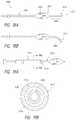
- a tissue modulation device(e.g., neuromodulation device adapted for intravascular hepatic neuromodulation) comprises an elongated shaft comprising a proximal end portion and a distal end portion and a balloon positioned at the distal end portion, the balloon being configured to transition from a non-inflated delivery configuration to an inflated deployment configuration.
- the ballooncomprises a plurality of electrode arrays positioned along an outer surface of the balloon, each of the electrode arrays comprising a plurality of spaced-apart electrodes.
- each of the electrode arraysis configured to be connected to a generator by separate connection wires such that each of the electrode arrays is individually controllable (e.g., activated or deactivated).
- the plurality of electrode arraysare arranged to form a spiral pattern along the outer surface of the balloon.
- at least one of the plurality of electrode arraysis adapted to be in contact with a vessel wall (e.g., a common hepatic artery, proper hepatic artery, gastroduodenal artery, splenic artery, celiac artery, renal artery).
- a vessel walle.g., a common hepatic artery, proper hepatic artery, gastroduodenal artery, splenic artery, celiac artery, renal artery.
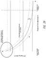
- a size of each of the plurality of electrode arrays in its longest aspectis less than or equal to a characteristic length of thermal conduction in body tissue.
- the plurality of spaced-apart electrodes in each array or group of electrodesare closely-spaced such that the electrodes are positioned within a region or area having a longest aspect or dimension that is no more than 6 mm (e.g., when the electrode array consists of four electrodes).
- each electrode arrayconsists of between two and eight spaced-apart electrodes (e.g., two, three, four, five, six, seven, eight electrodes).
- Each electrode arraymay have the same number of electrodes or some electrode arrays may have different numbers of electrodes than others.
- the number of electrode arrays or groupsranges from two to eight (e.g., two, three, four, five, six, seven, eight arrays or groups). However, more than eight arrays or groups may be present in other embodiments.
- the electrode arraysare coupled to the outer surface of the balloon by an adhesive. In some embodiments, the electrode arrays are coupled to a flexible substrate.
- the balloonmay comprise a coating covering an entire outer surface of the balloon except for active electrode areas of the electrodes or covering a substantial portion of the outer surface of the balloon and/or electrodes other than the active electrode areas.
- a portion of the connection wires spanning from the first electrode to the last electrode in at least one of the plurality of electrode arraysforms a zig-zag pattern.
- Each of the electrode arrays disposed on the outer surface of the balloonmay form the zig-zag pattern of connection wires to reduce overall spacing and to avoid folds of the balloon in a non-inflated configuration (e.g., to reduce overall profile).
- the devicecomprises one or more lesion spacing indicators, or markers, positioned along the distal end portion of the elongated shaft to facilitate controlled spacing of lesion zones.
- the lesion spacing indicator(s)e.g., radiopaque markers
- a method of ablating nerves surrounding a blood vessel having a controlled lesion spacing patterncomprises inserting a neuromodulation device within the blood vessel.
- the neuromodulation devicecomprises a first electrode and a second electrode spaced apart distal of the first electrode along a distal end portion of the neuromodulation device and at least one lesion spacing indicator positioned distal of the second electrode.
- the methodfurther comprises causing the first electrode to contact an inner wall of the blood vessel at a first contact location and the second electrode to contact the inner wall of the blood vessel at a second contact location, wherein the first contact location and the second contact location are spaced apart axially from each other by a separation distance.
- the methodfurther comprises causing the first electrode and the second electrode to deliver radiofrequency energy to the inner wall of the blood vessel while at the contact locations.
- the methodalso comprises repositioning the neuromodulation device axially within the blood vessel using the at least one lesion spacing indicator and causing the first electrode to contact the inner wall of the blood vessel at a third contact location and the second electrode to contact the inner wall at a fourth contact location, wherein the third contact location and the fourth contact location are spaced apart axially from each other by the separation distance.
- the neuromodulation devicemay then be removed from the blood vessel.
- the first location and the second locationare in different quadrants of the inner wall of the blood vessel with respect to each other and the third location and the fourth location are in different quadrants of the inner wall of the blood vessel with respect to each other.
- the first location and the third locationmay be in the same quadrant and the second location and the third location may be in the same quadrant.
- the neuromodulation devicemay be adapted to deflect or otherwise change configurations such that one of the first and second electrodes is in contact with the vessel wall at a first quadrant while the other of the first and second electrodes is in contact with the vessel wall at a second quadrant different from the first quadrant.
- the first and second electrodesare configured to come into contact with the vessel wall in quadrants on opposite sides of the vessel wall (e.g., contact locations spaced apart by about 180 degrees). In some embodiments, the first contact location and the second contact location are spaced apart circumferentially by between 120 degrees and 210 degrees. In some embodiments, the first contact location and the second contact location are spaced apart circumferentially by about 90 degrees.
- the first location and the second locationare in the same quadrant and the third location and the fourth location are in the same quadrant.
- the first and second electrodesmay be positioned into contact with an inner wall of the blood vessel in a first quadrant and activated to form spaced apart lesion zones in the first quadrant and then the neuromodulation device may be retracted or advanced by a distance using the at least one spacing indicator and the first and second electrodes may be positioned into contact with an inner wall of the blood vessel in a second quadrant different from the first quadrant (e.g., on an opposite side of the vessel circumference).
- the at least one lesion spacing indicatoris spaced apart axially from the second electrode by a distance that is equal to the separation distance. In other embodiments, the at least one lesion spacing indicator is spaced apart axially from the second electrode at distance that is twice the separation distance. In embodiments where two spaced-apart lesion spacing indicators positioned distal to the second electrode are used, a proximal lesion spacing indicator may be positioned adjacent the second electrode (e.g., within 2 mm, within 1 mm) and the spacing between the two spaced-apart lesion spacing indicators may be equal to or twice the separation distance.
- repositioning the neuromodulation device axially within the blood vesselcomprises aligning a distal one of the two lesion spacing indicators with a position of a proximal one of the two lesion spacing indicators prior to repositioning.
- the separation distancemay be between 3 mm and 8 mm (e.g., 3 mm, 4 mm, 5 mm, 6 mm, 7 mm, 8 mm).
- a neuromodulation system adapted for tissue contact sensing and modulation of tissuecomprises a neuromodulation device including an elongated shaft having a proximal end portion and a distal end portion and an electrode assembly positioned at the distal end portion of the elongated shaft.
- the electrode assemblycomprises an inner electrode element and an outer electrode element separated by an insulation layer, wherein the inner electrode element is concentric within the outer electrode element.
- the electrode assemblyis adapted to apply common mode signals to the inner electrode element and the outer electrode element to cause delivery of radiofrequency power sufficient to ablate tissue and to apply differential mode sensing signals between the inner electrode element and the outer electrode element to generate tissue contact sensing measurements to be received by a processing device adapted to determine a level of tissue contact based on the tissue contact sensing measurements.
- the tissue contact sensing measurementsmay comprise bipolar contact impedance measurements between the inner electrode member and the outer electrode member and/or temperature measurements obtained by one or more thermocouple leads within the inner electrode member.
- the systemcomprises a processing device configured to receive the tissue contact sensing measurements and to determine whether contact exists or a level of tissue contact based on the received tissue contact sensing measurements.
- the processing devicemay be configured (e.g., specifically programmed) to generate an output indicative of the level of tissue contact.
- the common mode signalshave a frequency range between 400 kHz and 650 kHz (e.g., between 400 kHz and 500 kHz, between 450 kHz and 600 kHz, between 550 kHz and 650 kHz, overlapping ranges thereof or any value of or within the recited ranges).
- the differential mode sensing signalshave a frequency outside the frequency range of the common mode signals.
- the differential mode sensing signalshave a frequency between 800 kHz and 20 MHz (e.g., between 800 kHz and 1 MHz between 1 MHz and 10 MHz, between 5 MHz and 15 MHz, between 10 MHz and 20 MHz, overlapping ranges thereof or any value of or within the recited ranges).
- a ratio of a contact surface area of the outer electrode to a contact surface are of the inner electrodeis between 5:1 and 25:1 (e.g., between 5:1 and 10:1, between 10:1 and 25:1, between 10:1 and 20:1, between 15:1 and 25:1, overlapping ranges thereof or any value of or within the recited ranges).
- the energy-based delivery systemscomprise cooling systems that are used to, for example, reduce thermal damage to regions surrounding the target area. For example, cooling may lower (or maintain) the temperature of tissue at below a particular threshold temperature (e.g., at or between 40 to 50 degrees Celsius), thereby preventing or reducing cell necrosis.
- Cooling balloons or other expandable cooling membersare used in some embodiments.
- ablation electrodesare positioned on a balloon, which is expanded using cooling fluid.
- cooling fluidis circulated through a delivery system (e.g., a catheter system).
- cooling fluid(such as pre-cooled saline) may be delivered (e.g., ejected) from a catheter device in the treatment region.
- cooling fluidis continuously or intermittently circulated internally within the catheter device to cool the endothelial wall in the absence of sufficient blood flow.
- tissue modulation devicese.g., neuromodulation devices, ablation catheters
- the tissue modulation devicesmay advantageously cause one or more electrodes to exert sufficient contact pressure on a vessel wall.
- the sufficient contact pressureis between about 0.1 g/mm 2 and about 100 g/mm 2 (e.g., between about 0.1 g/mm 2 and about 10 g/mm 2 , between about 5 g/mm 2 and about 20 g/mm 2 , between about 1 g/mm 2 and about 50 g/mm 2 , or overlapping ranges thereof).
- the therapeutically effective amount of RF energyis in the range of between about 300 J and about 1.5 kJ (e.g., about 300 J to about 1 kJ) per target location or total for all target locations.
- the therapeutically effective amount of RF energymay have a power level between about 0.1 W and about 14 W (e.g., between about 0.1 W and about 10 W, between about 3 W and about 8 W, between about 3 W and about 10 W) per target location.
- the tissue modulation device(e.g., neuromodulation device) comprises one or more lesion spacing indicators (e.g., radiopaque markers) positioned along the distal end portion of the elongated shaft (e.g., distal of the distal-most electrode) to facilitate controlled spacing of lesion zones.
- the lesion spacing indicatorsmay be positioned on a distal extension extending beyond the shape-set portion.
- the deviceconsists of two spaced-apart lesion indicators.
- one of the electrodesfunctions as one of the spaced-apart lesion-spacing indicators.
- the lesion-spacing indicatorsmay comprise radiopaque markers visible under fluoroscopy or other imaging technique.
- the lesion-spacing indicatorsmay be spaced apart at a distance equal to the distance between the first monopolar electrode and the second monopolar electrode when the shape-set portion is in the deployed configuration or at a distance that is twice the distance between the first monopolar electrode and the second monopolar electrode when the shape-set portion is in the deployed configuration. Other distances may be used as desired and/or required.
- a tissue modulation device(e.g., neuromodulation device adapted for intravascular hepatic neuromodulation) comprises an elongated shaft comprising a proximal end portion and a distal end portion and a balloon positioned at the distal end portion, the balloon being configured to transition from a non-inflated delivery configuration to an inflated deployment configuration.
- the ballooncomprises a plurality of electrode arrays positioned along an outer surface of the balloon, each of the electrode arrays comprising a plurality of spaced-apart electrodes.
- each of the electrode arraysis configured to be connected to a generator by separate connection wires such that each of the electrode arrays is individually controllable (e.g., activated or deactivated).
- the plurality of electrode arraysare arranged to form a spiral pattern along the outer surface of the balloon.
- at least one of the plurality of electrode arraysis adapted to be in contact with a vessel wall (e.g., a common hepatic artery, proper hepatic artery, gastroduodenal artery, splenic artery, celiac artery, renal artery).
- a vessel walle.g., a common hepatic artery, proper hepatic artery, gastroduodenal artery, splenic artery, celiac artery, renal artery.
- a size of each of the plurality of electrode arrays in its longest aspectis less than or equal to a characteristic length of thermal conduction in body tissue.
- the plurality of spaced-apart electrodes in each array or group of electrodesare closely-spaced such that the electrodes are positioned within a region or area having a longest aspect or dimension that is no more than 6 mm (e.g., when the electrode array consists of four electrodes).
- each electrode arrayconsists of between two and eight spaced-apart electrodes (e.g., two, three, four, five, six, seven, eight electrodes).
- Each electrode arraymay have the same number of electrodes or some electrode arrays may have different numbers of electrodes than others.
- the number of electrode arrays or groupsranges from two to eight (e.g., two, three, four, five, six, seven, eight arrays or groups). However, more than eight arrays or groups may be present in other embodiments.
- the electrode arraysare coupled to the outer surface of the balloon by an adhesive. In some embodiments, the electrode arrays are coupled to a flexible substrate.
- the balloonmay comprise a coating covering an entire outer surface of the balloon except for active electrode areas of the electrodes or covering a substantial portion of the outer surface of the balloon and/or electrodes other than the active electrode areas.
- a portion of the connection wires spanning from the first electrode to the last electrode in at least one of the plurality of electrode arraysforms a zig-zag pattern.
- Each of the electrode arrays disposed on the outer surface of the balloonmay form the zig-zag pattern of connection wires to reduce overall spacing and to avoid folds of the balloon in a non-inflated configuration (e.g., to reduce overall profile).
- the devicecomprises one or more lesion spacing indicators positioned along the distal end portion of the elongated shaft to facilitate controlled spacing of lesion zones.
- the lesion spacing indicator(s)e.g., radiopaque markers
- the lesion spacing indicator(s)may be positioned on a distal extension distal of the balloon, may be positioned proximal of the balloon, and/or may be positioned within the balloon.
- the methodcomprises providing cooling to a portion of the common hepatic artery that is or is not being targeted by the RF energy or to the at least one electrode.
- coolingcomprises infusing saline within the catheter or within the blood flow adjacent the at least one electrode.
- coolingcomprises obstructing flow upstream of the at least one electrode to increase the arterial flow rate past the at least one electrode, thereby providing convective cooling due to increased blood flow.
- flowis diverted or channeled toward the at least one electrode (e.g., from a center of the vessel toward a wall of the vessel).
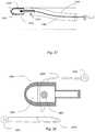
- a device for thermally-induced hepatic neuromodulationcomprises a catheter body having a proximal end and a distal end and a lumen extending from the proximal end to the distal end.
- the catheter bodyis configured for percutaneous, intravascular placement within a hepatic artery branch.
- the devicemay comprise an actuatable portion at the distal end of the catheter body and at least one electrode disposed on the actuatable portion.
- the actuatable portionis configured to provide stabilization of the catheter within the hepatic artery branch and to facilitate contact of the at least one electrode with an inner arterial wall of hepatic artery branch.
- the at least one electrode or transducermay be configured to be activated to deliver thermal energy sufficient to achieve modulation (e.g., denervation, ablation, stimulation) of at least a portion of the hepatic artery branch (e.g., a segment of the common hepatic artery having a length of 30 mm or less, 24 mm or less, 20 mm or less, or between 20 mm and 30 mm).
- the at least one electrode or transducermay be repositioned and activated at multiple positions along the length of and/or around the circumference of the hepatic artery branch.
- the at least one electrode or transducermay comprise one or more monopolar electrodes or one or more bipolar electrode pairs.
- a neuromodulation deviceconsists or consists essentially of only two electrodes or transducers. In some embodiments, a neuromodulation device consists or consists essentially only of four electrodes or transducers. In various embodiments, the electrodes or transducers advantageously facilitate ablation of only two quadrants or sections of the vessel wall instead of all four quadrants. In some embodiments, electrodes or transducers are positioned to maintain 180-degree offset between the electrodes or transducers and to provide spacing between the electrodes or transducers along the length of the vessel, as desired or required.
- Electrodes or transducersmay be spaced circumferentially (or radially) and/or axially (or longitudinally) and may be independently adjustable to adjust circumferential and/or axial spacing of the electrodes (and treatment sites) depending on the vessel, patient, or treatment parameters.
- an aspect of the disclosureis directed towards several alternative designs, materials and methods of manufacturing medical device structures and assemblies for an ablation catheter.
- an ablation catheterconfigured to be navigated through a vessel to ablate tissue, the ablation catheter comprising an elongate shaft having a proximal and distal end.
- An electrodeis positioned near the distal end of the elongate shaft, and is configured to transmit radiofrequency energy into a vessel wall.
- a substantially enclosed space within the electrodee.g., hollow electrode or cavity
- an agitator or stirreris provided to increase fluid flow or circulation within the enclosed fluid space.
- Some embodimentspertain to a method of ablating perivascular nerves, comprising navigating an ablation catheter through a vasculature to a vessel lumen of a vessel, the ablation catheter including an elongate shaft, having an electrode near the distal end of the elongate shaft and a substantially enclosed space (e.g., hollow cavity) within the electrode.
- the methodfurther includes causing fluid within the substantially enclosed space to flow within the closed space thereby providing free or forced convective heat transfer that facilitates heat transfer from the vessel wall into the blood stream.
- This methodcan be used in conjunction with any of the catheters, devices, instruments, or systems described herein.
- an ablation cathetercomprises a catheter shaft having a proximal end and a distal end and an electrode positioned near the distal end of the catheter shaft and configured to transmit radiofrequency energy into a vessel wall.
- the electrodecomprises a substantially enclosed space that comprises an agitator.
- the substantially enclosed spaceis configured to contain fluid to facilitate heat transfer away from the vessel wall.
- the cathetercomprises an actuator adapted to engage said agitator.
- the substantially enclosed spacecomprises a plurality of agitators (e.g., two, three, four or more).
- the substantially enclosed spacemay be expandable and/or may be formed by a balloon (e.g., compliant or semi-compliant balloon).
- the substantially enclosed spaceis configured to be filled with fluid during use.
- the substantially enclosed spaceis prefilled with fluid during manufacture.
- the substantially enclosed spacemay be only substantially enclosed in that it is configured to leak at a relatively slow rate.
- the substantially enclosed spacemay be configured to leak fluid at a leakage rate of less than 10 ml/min.
- the expandable chambermay comprise or contain a substantially closed fluid space configured to facilitate heat transfer away from the vessel wall.
- the substantially closed fluid spacecomprises fluid that is either filled during manufacture or filled at the time of use within the vessel (e.g., after insertion to a desired location within the vessel).
- a cathetercomprises an elongate shaft having a proximal end and a distal end, an expandable chamber positioned near the distal end of the elongate shaft, and a valved inlet to the expandable chamber providing restricted flow in a first direction and unrestricted flow in a second direction.
- the valved inletis configured to provide convective flow of fluid within the expandable chamber.
- the valved inletis configured to entrain additional fluid within the expandable chamber.
- an ablation cathetercomprises an elongate shaft having a proximal end and a distal end, a fluid delivery lumen, an expandable chamber positioned near the distal end of the elongate shaft, and an outlet providing restricted flow of fluid through the expandable chamber.
- the outletmay be an orifice in a catheter lumen or a channel within a balloon waist of a balloon of the ablation catheter.
- a cathetercomprises an elongate shaft having a proximal end and a distal end, a fluid delivery lumen, a chamber positioned near the distal end of the elongate shaft, and a compliance volume configured to allow flow of fluid (e.g., gas or liquid) into and out of the chamber.
- the compliance volumeis distal to the chamber.
- the compliance volumeis proximal to the chamber.
- the compliance volumemay be a gas pocket.
- the compliance volumemay be located within the elongate shaft and/or within the chamber.
- the compliance volumemay comprise a compliant balloon or an elastic mechanical device.
- a vessel lumene.g., lumen of a hepatic artery, a renal artery, a gastroduodenal artery, a splenic artery, a mesente
- a system for ablating tissue adjacent the lumen of a vessel in a patientcomprises an ablation catheter, a controller configured to regulate power delivery to said ablation catheter, a first cable configured to transmit power from the controller to the ablation catheter, a second electrode configured to be placed in electrical contact with the patient; and a second cable configured to transmit power from the second electrode to the controller.
- the ablation cathetermay comprise an elongate catheter shaft having a proximal and a distal end, a first electrode positioned near the distal end of the catheter shaft and configured to transmit radiofrequency energy into a vessel wall, and a substantially enclosed space within the first electrode.
- the substantially enclosed spacemay comprise one or more agitators.
- the systemcomprises a second electrode spaced from the first electrode, the second electrode comprising a substantially enclosed space and one or more agitators within the substantially enclosed space.
- an ablation cathetercomprises a catheter shaft having a proximal end and a distal end and an electrode positioned near the distal end of the catheter shaft and configured to transmit radiofrequency energy into a vessel wall.
- the electrodecomprises a substantially enclosed space that comprises a phase change material.
- the substantially enclosed spaceis configured to contain fluid to facilitate heat transfer away from the vessel wall.
- the phase change materialfunctions as a heat pump.
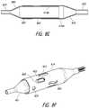
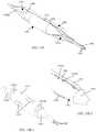
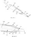
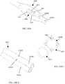
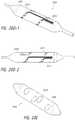
- an ablation balloon catheteris adapted to deliver ablation electrodes to a treatment site and deploy the electrodes into a treatment position.
- one or more electrodes with attached electrical conductorsare affixed to an expanding balloon assembly mounted near the distal end of a catheter.
- at least a portion of the electrodes and electrical conductorsare enclosed by a flexible covering or sleeve.
- the flexible covering or sleeveis a cylindrical tube. In other embodiments, the flexible covering or sleeve is a conformal coating.
- an intraluminal ablation catheter adapted to ablate tissueincludes a shaft having a proximal end and a distal end.
- a multi-lumen balloonis positioned near the distal end of the shaft.
- the multi-lumen ballooncomprises at least one main lumen and at least one accessory lumen.
- at least one electrodeis affixed to the multi-lumen balloon.
- the at least one electrodemay comprise a surface electrically exposed to the tissue to be ablated or otherwise treated.
- the catheteralso includes electrical conductors passing from the electrode to a power source.
- At least one electrical conductorpasses through at least one accessory lumen.
- At least one accessory lumenmay be configured to convey fluid.
- the at least one accessory lumenis configured to convey cooling fluid past a hot surface of the balloon while energy is being delivered by the at least one electrode.
- the cooling fluidis delivered to an accessory lumen through an infusion lumen.
- the cooling fluidmay be removed from the balloon through a return lumen.
- a portion of an electrode assemblyis contained within an accessory lumen.
- a balloon ablation catheterin accordance with several embodiments, includes a proximal manifold and an elongate shaft having a plurality of lumens.
- the plurality of lumensincludes a guidewire lumen and a fluid infusion lumen.
- the catheteralso includes an expandable member (e.g., balloon) coupled to a distal end of the elongate shaft.
- the balloonincludes a plurality of electrodes coupled thereto.
- the catheterfurther includes a plurality of electrical conductors extending from a port of the proximal manifold to each of the plurality of electrodes. In some embodiments, the catheter does not include more than four electrodes.
- two electrodesare advantageous because 180 degree offset may be maintained and vessels having short lengths (e.g., common hepatic artery having a length of about 30 mm) may be modulated.
- four electrodesare advantageous because of one or more of the following benefits: (i) increased vessel lengths may be treated while still maintaining 90-degree or 180 degree offset; (ii) ability to place multiple electrodes in shortest vessel length while controlling radial or circumferential spacing between two electrodes, (iii) increased ability to adjust electrode placement characteristics in difficult anatomy (e.g., tortuous, short length, severe tapers); allows operator to work around side branches or focal disease sites; (iv) allows operator to perform treatments in multiples of two; (v) reduces treatable territory lost in the vessel due to incomplete treatment (e.g., ablation) cycles; and/or (vi) maintains the ability to radially and/or longitudinally offset space between sets of treatments (e.g., ablations).
- treatmentmay be better controlled (e.g., radial and/or length spacing between electrode pairs may be controlled) and the number of treatment sites or catheter placements may be reduced to perform four treatments (e.g., ablations) compared to devices having more than four electrodes.
- Using only two electrodes or only four electrodesis viable in several embodiments due to, for example, the increased efficiency of the electrodes and the treatment parameters used. If two electrodes are used, the two electrodes may comprise monopolar electrodes or a bipolar electrode pair. If four electrodes are used, the four electrodes may comprise monopolar electrodes or two bipolar electrode pairs. Electrodes may be toggled on and off to customize treatment (e.g., based on length of desired lesion zone, length of vessel, etc.).
- the cathetermay include a flexible outer sleeve covering at least a portion of a length of the balloon and at least a portion of the plurality of electrical conductors so as to contain the portion of the plurality of electrical conductors.
- the flexible outer sleevemay be removably coupled to the balloon such that the outer sleeve may be removed from the balloon prior to expansion or inflation of the balloon.
- the flexible outer sleeveis permanently coupled (e.g., bonded, adhered, or otherwise non-removably coupled) to the balloon.
- the flexible outer sleeveincludes a plurality of fenestrations aligned with at least some of the plurality of electrodes.
- the flexible outer sleeveincludes one or more openings, slots or holes separate from the fenestrations that are not aligned with any of the electrodes. These one or more openings, slots or holes may advantageously be adapted to provide increased flexibility to the balloon, to facilitate folding and/or to reduce heat.
- the plurality of electrodesis directly bonded (e.g., soldered, welded, adhered with adhesive) to the balloon without the use of flex circuits.
- a respective one of the plurality of electrical conductorsmay be bonded (e.g., soldered, welded, adhered with adhesive) to a corresponding one or more of the plurality of electrodes.
- one or more of the plurality of electrodesincludes a channel along a length of a surface of the electrode adapted to receive an electrical conductor, thereby providing a reduced outer profile.
- One or more of the electrodesmay be curved to conform to an outer surface of the balloon when in an inflated configuration.
- the balloonmay include a plurality of divots, or recesses adapted to receive a respective one of the plurality of electrodes such that an outer diameter of the balloon at each electrode location is no larger than the outer diameter of the balloon adjacent to each electrode.
- the catheterincludes a distal tracking segment coupled to a distal end of the expandable member (e.g., balloon).
- the distal tracking segmentmay advantageously be adapted to vary a flexibility of the catheter from distal to proximal or from proximal to distal.
- at least a portion (e.g., a distal tip) of the distal tracking segmentcomprises radiopaque material.
- the distal tracking segmentmay have a pre-shaped configuration (e.g., as a result of shape memory material that is pre-shaped to a particular shape) or the distal tracking segment may be configured to be shaped by an operator to have a particular desired shape or geometry (e.g., a shape that corresponds to a shape or geometry of vasculature through which a distal end portion of the catheter must traverse.
- the fluid infusion lumenincludes at least one orifice that is oriented so as to direct a fluid jet directly at a surface of one of the plurality of electrodes.
- the cathetermay also be coupled to a moveable outer sheath.
- the moveable outer sheathmay be coupled along a length of the elongate shaft of the catheter and may be moveable with respect to the elongate shaft. In some embodiments, translational movement of the moveable outer sheath adjusts a push force on a distal end portion of the catheter or adjusts a flexibility of the elongate shaft of the catheter.
- the moveable outer sheathmay comprise a captive support shaft or guide sheath adapted to deliver (e.g., infuse) fluid or dye to a blood vessel.
- the sheathmay be less than 6 French and may have variable stiffness along its length.
- the moveable outer sheathmay be reinforced with braids or coils.
- the moveable outer sheathmay be adapted to move with respect to the catheter shaft by greater than 5 cm or greater than 10 cm.
- the flexible outer sleeveis integrally coupled to the moveable outer sheath.
- the flexible outer sleevemay be a proximal portion of the moveable outer sheath that is moveable with respect to the elongate shaft such that the outer sleeve may be removed from covering the balloon (and the one or more electrodes of the balloon) prior to expansion or inflation of the balloon.
- a method of delivering therapeutic energy to tissue using a balloon catheterincludes positioning a balloon of a balloon catheter at a first placement location within a vessel (e.g., a common hepatic artery) of a subject from which energy is to be delivered, wherein the balloon comprises one or more energy delivery members (e.g., electrodes, ultrasound transducers or delivery elements) that are configured to be independently activated.
- the methodfurther includes determining at least one of a position and orientation of each of the one or more energy delivery members at the first placement location.
- the methodalso includes causing at least one of the one or more energy delivery members not to be activated at the first placement location based on at least one of the position or orientation of the at least one energy delivery member.
- the methodfurther includes determining, based on a determined position and orientation of each of the one or more energy delivery members, that energy delivery by at least one of the one or more energy delivery members may affect a non-target adjacent structure (e.g., a structure or tissue desired not to be affected or desired not to receive any energy or heat), such as a pancreas, bile duct, portal vein, lymph node, etc.).
- a non-target adjacent structuree.g., a structure or tissue desired not to be affected or desired not to receive any energy or heat
- the methodincludes determining, based on the determined position of the one or more energy delivery members, that at least one of the energy delivery members is positioned beyond a boundary (e.g., a proximal or distal end) of the vessel such that energy delivery is customized to a vessel length.
- the at least one of the energy delivery members determined to be positioned beyond the boundary of the vesselmay not be activated when others of the energy delivery members are activated so as not to deliver energy to a location beyond the boundary of the vessel, thereby facilitating customized treatment based on vessel length.
- the determinations of position and/or orientationmay be based on various imaging methods or mechanisms (e.g., fluoroscopy, computerized tomography (CT), radiographic, angiographic, optical coherence tomography (OCT), intravascular ultrasound (IVUS), Doppler, thermography, magnetic resonance (MR) imaging and/or the like).
- a method of delivering therapeutic energy to tissue using a balloon catheterincludes positioning a balloon of a balloon catheter at a first placement location within a vessel of a subject.
- the balloonmay include a plurality of electrodes arranged in an electrode pattern comprised of or consisting of four electrodes.
- the methodincludes activating (simultaneously or independently) a first pair of the plurality of electrodes at the first placement location, wherein the first pair of the plurality of electrodes are spaced apart circumferentially and axially along the balloon.
- the methodalso includes repositioning the balloon at a second placement location within the vessel of the subject and activating (simultaneously or independently) a second pair of the plurality of electrodes different than the first pair of the plurality of electrodes at the second placement location.
- the second pair of the plurality of electrodesis spaced apart circumferentially and axially along the balloon from the first pair.
- the methodcreates a lesion pattern (e.g., a spiral lesion pattern) that is different than the electrode pattern.
- the electrodes of the first pairare spaced apart circumferentially from each other by 90 degrees and the electrodes of the second pair are spaced apart from each other circumferentially by 90 degrees.
- a first electrode of the first pair and a first electrode of the second pairmay be spaced apart circumferentially by 180 degrees and aligned along a plane that is perpendicular to an axis (e.g., longitudinal axis) of the vessel.
- a second electrode of the first pair and a second electrode of the second pairmay also be spaced apart circumferentially by 180 degrees and aligned along a plane that is perpendicular to an axis (e.g., longitudinal axis) of the vessel.
- the lesion patternis adapted to increase perivascular circumferential coverage without causing circumferential coverage along a cross-section of a vessel wall.
- a method of delivering therapeutic energy to tissue using a balloon catheterincludes positioning a balloon of a balloon catheter at a first placement location within a vessel (e.g., common hepatic artery) of a subject.
- the balloonmay include a plurality of electrodes arranged in an electrode pattern comprised of six electrodes.
- the methodincludes activating a first triplet of the plurality of electrodes at the first placement location, wherein the first triplet of the plurality of electrodes are spaced apart circumferentially and axially from each other along the balloon.
- the methodalso includes repositioning the balloon at a second placement location within the vessel of the subject and activating a second triplet of the plurality of electrodes different than the first triplet of the plurality of electrodes at the second placement location.
- the second triplet of the plurality of electrodesare spaced apart circumferentially and axially from each other along the balloon.
- the lesion pattern created by the activation of the first triplet of electrodes and the second triplet of electrodesmay advantageously be different than the electrode pattern.
- the first triplet of the plurality of electrodesare spaced apart circumferentially from each other by 120 degrees and the second triplet of the plurality of electrodes are spaced apart circumferentially from each other by 120 degrees.
- an intraluminal ablation catheter adapted for hepatic denervationincludes a proximal manifold.
- the proximal manifoldmay comprise one or more ports (e.g., coolant fluid infusion port, dye delivery port, guidewire port, balloon inflation port).
- the cathetermay also include an elongate shaft comprising at least one lumen.
- the elongate shaftcomprises a central longitudinal axis extending along its length.
- the catheteralso includes an expandable member (e.g., inflatable balloon) coupled to a distal end portion of the elongate shaft.
- the expandable memberis adapted to transition between a non-expanded (e.g., non-inflated, folded) configuration and an expanded (e.g., inflated, unfolded) configuration.
- the expandable membercomprises or consists of four electrodes.
- a first electrode and a second electrode of the four electrodesmay be located within a first circumferential cross-section along the expandable member at a first axial distance from a distal end of the expandable member and may be located in opposite quadrants from each other (e.g., 180 degrees apart or approximately 180 degrees apart circumferentially) about the central longitudinal axis of the elongate shaft when the expandable member is in the expanded configuration.
- a third electrode and a fourth electrode of the four electrodesmay be located within a second circumferential cross-section along the expandable member at a second axial distance from the distal end of the expandable member and are located in opposite quadrants from each other (e.g., 180 degrees apart or approximately 180 degrees apart circumferentially) about the central longitudinal axis of the elongate shaft when the expandable member is in the expanded configuration.
- the second axial distanceis different from the first axial distance.
- the catheteralso includes means for cooling the four electrodes.
- the third and fourth electrodesare each circumferentially offset from the first and second electrodes such that they are in different quadrants than the first and second electrodes.
- the third and fourth electrodesmay be offset from the first and second electrodes by 90 degrees.
- a center point of the first and second electrodesare aligned along a first plane that is substantially perpendicular to the central longitudinal axis of the elongate shaft and a center point of the third and fourth electrodes are aligned along a second plane that is substantially perpendicular to the central longitudinal axis of the elongate shaft.
- the at least one lumen of the elongate shaftmay include a first central guidewire lumen adapted to track a guidewire and at least one fluid delivery lumen in fluid communication with an interior of the balloon and adapted to deliver coolant within the balloon and/or fluid to inflate/deflate the balloon to cause it to transition between the expanded and non-expanded configurations.
- the means for coolingmay include one or more orifices adapted to direct fluid jets toward at least one of the four electrodes.
- the orificesmay be positioned along an inner balloon within the balloon (which may be referred to as an outer balloon in such embodiments), along a fluid delivery lumen, or along other structures internal to the balloon.
- at least one orificeis positioned adjacent each of the four electrodes such that each of the four electrodes is directly cooled.
- One or more nozzles or eductorsmay be positioned adjacent the one or more orifices such that each of the one or more nozzles or eductors is configured to direct the fluid jets toward at least one surface of a respective one the four electrodes.
- a second balloone.g., inner balloon
- the one or more orificesare positioned along the second balloon at a location adjacent one, some or all of the electrodes.
- the means for coolingcomprises a fluid inlet lumen having an outlet located within the balloon and adjacent to at least one of (e.g., one, some or all of) the four electrodes.
- the balloonincludes fenestrations, with each of the four electrodes being located within a respective fenestration. In some embodiments, each of the four electrodes is directly bonded to an outer surface of the balloon without the use of a flex circuit.
- the catheterincludes one or more lesion spacing indicators (e.g., radiopaque markers) positioned along the elongate shaft to facilitate controlled spacing of lesion zones. The lesion spacing indicator(s) may be positioned distal to the balloon, proximal to the balloon, and/or within the balloon.
- each of the four electrodesincludes a channel along a length of a surface of the electrode adapted to receive an electrical conductor.
- a separate electrical conductormay be coupled to each electrode and may extend from the respective electrode to the proximal manifold.
- the catheterfurther includes a distal tracking segment coupled to a distal end of the expandable member (e.g., balloon) or coupled to a distal end of the elongate shaft or the at least one lumen.
- the distal tracking segmentis adapted to vary a flexibility of the catheter from distal to proximal.
- a distal tip of the distal tracking segmentmay comprise radiopaque material.
- the distal tracking segmentmay have a pre-shaped configuration or may be configured to be shaped by an operator either prior to insertion or after insertion.
- the balloonincludes a plurality of divots, wherein each of the plurality of divots is adapted to receive a respective one of the plurality of electrodes such that an outer diameter of the balloon at each electrode location is no larger than the outer diameter of the balloon adjacent to each electrode.
- the cathetermay also include a moveable outer sheath (e.g., captive support sleeve) coupled along a length of the elongate shaft and moveable with respect to the elongate shaft, wherein translational movement of the moveable outer sheath adjusts a push force on a distal end portion of the catheter or adjusts a flexibility of the elongate shaft.
- a moveable outer sheathe.g., captive support sleeve
- the balloonis adapted to be substantially cylindrical when in the expanded configuration such that each of the four electrodes is substantially equidistant circumferentially from each of the other four electrodes when the balloon is in the expanded configuration.
- each of the four electrodesis formed of a cluster of two electrode elements positioned circumferentially adjacent to each other and adapted to function as a single monopolar electrode.
- a surface area of the cluster of two electrode elementsranges between 5 mm 2 and 40 mm 2 (e.g., between 5 mm 2 and 20 mm 2 , between 10 mm 2 and 40 mm 2 ).
- a maximum width of any of the two electrode elementsis less than one-fourth of the circumference of the expandable member when in the expanded configuration.
- the two electrode elementsmay be positioned to straddle a folding line of the expandable member.
- the cluster of two electrode elementshas a substantially square aspect ratio.
- the cathetermay advantageously be sized and adapted to be advanced to a location within a hepatic artery (e.g., common hepatic artery).
- an intraluminal ablation catheterincludes a proximal manifold, an elongate shaft comprising at least one lumen and a first balloon coupled to a distal end portion of the elongate shaft, wherein the balloon is adapted to transition between a folded configuration and an expanded, unfolded configuration.
- the balloonincludes or consists of four electrodes positioned along the balloon, with a first electrode and a second electrode of the four electrodes being located in a first circumferential cross-sectional plane along the balloon and located in opposite quadrants from each other around the circumference of the balloon when the balloon is in the expanded, unfolded configuration, and a third electrode and a fourth electrode of the four electrodes being located within a second circumferential cross-sectional plane along the balloon and located in opposite quadrants from each other around the circumference of the balloon when the balloon is in the expanded, unfolded configuration.
- the second circumferential cross-sectional planeis axially offset from the first circumferential cross-sectional plane.
- the catheteralso includes means for cooling the four electrodes.
- the third electrode and the fourth electrodeare located in different quadrants circumferentially than the first electrode and the second electrode when the balloon is in the expanded, unfolded configuration.
- the third electrode and the fourth electrodemay be located in quadrants that are circumferentially offset by 90 degrees from the quadrants in which the first electrode and the second electrode are located when the balloon is in the expanded, unfolded configuration.
- the first electrode and the second electrodemay be located 180 degrees apart circumferentially from each other about a central longitudinal axis of the elongate shaft.
- the third electrode and the fourth electrodemay be located 180 degrees apart circumferentially from each other about the central longitudinal axis of the elongate shaft.
- the third and fourth electrodesare each circumferentially offset from the first and second electrodes by 90 degrees when the balloon is in the expanded, unfolded configuration.
- the at least one lumenincludes a first central guidewire lumen adapted to track a guidewire and at least one fluid delivery lumen in fluid communication with an interior of the balloon and adapted to deliver coolant and/or other fluid within the balloon.
- the means for coolingmay include one or more orifices adapted to direct fluid jets toward at least one of the four electrodes.
- the orificesmay be positioned along an inner balloon within the balloon (which may be referred to as an outer balloon in such embodiments), along a fluid delivery lumen, or along other structures internal to the balloon.
- at least one orificeis positioned adjacent each of the four electrodes such that each of the four electrodes is directly cooled.
- One or more nozzles or eductorsmay be positioned adjacent the one or more orifices such that each of the one or more nozzles or eductors is configured to direct the fluid jets toward at least one surface of a respective one the four electrodes.
- a second balloone.g., inner balloon
- the balloone.g., outer balloon
- the means for coolingcomprises a fluid inlet lumen having an outlet located within the balloon and adjacent to at least one of (e.g., one, some or all of) the four electrodes.
- the balloonincludes fenestrations, with each of the four electrodes being located within a respective fenestration. In some embodiments, each of the four electrodes is directly bonded to an outer surface of the balloon without the use of a flex circuit.
- the catheterincludes one or more lesion spacing indicators (e.g., radiopaque markers) positioned along the elongate shaft to facilitate controlled spacing of lesion zones. The lesion spacing indicator(s) may be positioned distal to the balloon, proximal to the balloon, and/or within the balloon.
- each of the four electrodesincludes a channel along a length of a surface of the electrode adapted to receive an electrical conductor.
- a separate electrical conductormay be coupled to each electrode and may extend from the respective electrode to the proximal manifold.
- the catheterfurther includes a distal tracking segment coupled to a distal end of the balloon or coupled to a distal end of the elongate shaft or the at least one lumen.
- the distal tracking segmentis adapted to vary a flexibility of the catheter from distal to proximal.
- a distal tip of the distal tracking segmentmay comprise radiopaque material.
- the distal tracking segmentmay have a pre-shaped configuration or may be configured to be shaped by an operator either prior to insertion or after insertion.
- the balloonincludes a plurality of divots, wherein each of the plurality of divots is adapted to receive a respective one of the plurality of electrodes such that an outer diameter of the balloon at each electrode location is no larger than the outer diameter of the balloon adjacent to each electrode.
- the cathetermay also include a moveable outer sheath (e.g., captive support sleeve) coupled along a length of the elongate shaft and moveable with respect to the elongate shaft, wherein translational movement of the moveable outer sheath adjusts a push force on a distal end portion of the catheter or adjusts a flexibility of the elongate shaft.
- a moveable outer sheathe.g., captive support sleeve
- the balloonis adapted to be substantially cylindrical when in the expanded configuration such that each of the four electrodes is substantially equidistant circumferentially from each of the other four electrodes when the balloon is in the expanded configuration.
- each of the four electrodesis formed of a cluster of two electrode elements positioned circumferentially adjacent to each other and adapted to function as a single monopolar electrode.
- a surface area of the cluster of two electrode elementsranges between 5 mm 2 and 40 mm 2 (e.g., between 5 mm 2 and 20 mm 2 , between 10 mm 2 and 40 mm 2 ).
- a maximum width of any of the two electrode elementsis less than one-fourth of the circumference of the expandable member when in the expanded configuration.
- the two electrode elementsmay be positioned to straddle a folding line of the expandable member.
- the cluster of two electrode elementshas a substantially square aspect ratio.
- the cathetermay advantageously be sized and adapted to be advanced to a location within a hepatic artery (e.g., common hepatic artery).
- an intraluminal ablation catheterincludes a proximal manifold, an elongate shaft comprising at least one lumen, and a first balloon coupled along the elongate shaft, wherein the balloon is adapted to transition between a folded configuration and an expanded, unfolded configuration.
- the balloonmay include four clusters of electrodes each comprising two electrode members positioned circumferentially adjacent to each other and aligned axially along the length of the balloon. Each of the four clusters may be positioned in a different circumferential quadrant of the balloon when in the expanded, unfolded configuration. In some embodiments, each of the four clusters is spaced apart axially from each of the other three clusters.
- the catheteralso includes means for directly cooling the four clusters of electrode members.
- the four clusters of electrode membersare positioned such that the clusters collectively form a spiral pattern along a length of the balloon.
- each successive cluster moving from a distal end to a proximal end of the balloonis circumferentially offset by 90 degrees or approximately 90 degrees from the previous cluster.
- a first two of the four clustersare circumferentially offset from each other by 180 degrees or approximately 180 degrees and wherein a second two of the four clusters are circumferentially offset from each other by 180 degrees or approximately 180 degrees.
- the at least one lumenincludes a first central guidewire lumen adapted to track a guidewire and at least one fluid delivery lumen in fluid communication with an interior of the balloon and adapted to deliver coolant and/or other fluid within the balloon.
- the means for coolingincludes one or more orifices adapted to direct fluid jets toward at least one of the four clusters.
- the orificesmay be positioned along an inner balloon within the balloon (which may be referred to as an outer balloon in such embodiments), along a fluid delivery lumen, or along other structures internal to the balloon.
- at least one orificeis positioned adjacent each of the four clusters such that each of the four clusters is directly cooled.
- One or more nozzles or eductorsmay be positioned adjacent the one or more orifices such that each of the one or more nozzles or eductors is configured to direct the fluid jets toward at least one of the four clusters.
- a second balloone.g., inner balloon
- the balloone.g., outer balloon
- the means for coolingcomprises a fluid inlet lumen having an outlet located within the balloon and adjacent to at least one of (e.g., one, some or all of) the four clusters.
- the electrode members of the four clustersare directly bonded to an outer surface of the balloon without the use of a flex circuit.
- the catheterincludes one or more lesion spacing indicators (e.g., radiopaque markers) positioned along the elongate shaft to facilitate controlled spacing of lesion zones.
- the lesion spacing indicator(s)may be positioned distal to the balloon, proximal to the balloon, and/or within the balloon.
- each of the electrode membersincludes a channel along a length of a surface of the electrode member adapted to receive an electrical conductor.
- a separate electrical conductormay be coupled to each electrode member or a single electrical conductor may be coupled to all electrode members of an electrode cluster and may extend from the respective electrode to the proximal manifold.
- the catheterfurther includes a distal tracking segment coupled to a distal end of the balloon or coupled to a distal end of the elongate shaft or the at least one lumen.
- the distal tracking segmentis adapted to vary a flexibility of the catheter from distal to proximal.
- a distal tip of the distal tracking segmentmay comprise radiopaque material.
- the distal tracking segmentmay have a pre-shaped configuration or may be configured to be shaped by an operator either prior to insertion or after insertion.
- the cathetermay also include a moveable outer sheath (e.g., captive support sleeve) coupled along a length of the elongate shaft and moveable with respect to the elongate shaft, wherein translational movement of the moveable outer sheath adjusts a push force on a distal end portion of the catheter or adjusts a flexibility of the elongate shaft.
- a moveable outer sheathe.g., captive support sleeve
- the balloonis adapted to be substantially cylindrical when in the expanded configuration such that each of the four clusters is substantially equidistant circumferentially from each of the other four clusters when the balloon is in the expanded configuration.
- a surface area of the cluster of two electrode membersranges between 5 mm 2 and 40 mm 2 (e.g., between 5 mm 2 and 20 mm 2 , between 10 mm 2 and 40 mm 2 ). In some embodiments, a maximum width of any of the two electrode members is less than one-fourth of the circumference of the expandable member when in the expanded configuration.
- the two electrode members of each clustermay be positioned to straddle a folding line of the expandable member.
- the cluster of two electrode elementshas a substantially square aspect ratio. Each cluster may include three, four, five, six or more than six electrode elements.
- the cathetermay advantageously be sized and adapted to be advanced to a location within a hepatic artery (e.g., common hepatic artery).
- the embodiments hereinalso contemplate neuromodulation or tissue modulation of regions other than the liver or hepatic vessels.
- the catheters, devices and systems described hereinmay also be used for renal denervation (e.g., by modulating the nerves in one or both renal arteries), for glucose or lipid regulation by modulating the nerves that innervate the pancreas, kidney, duodenum, jejunum and/or stomach, for cardiac ablation, for pulmonary tissue or vessel ablation or neuromodulation, as well as other targets and indications described herein.
- the devices and systems summarized abovemay be used within vessels other than a hepatic artery, such as a renal artery, a gastroduodenal artery, a celiac artery or a splenic artery.
- the devices and systemsmay be used within one or more renal arteries or veins and may be suitable for treating hypertension or other conditions associated with modulation of nerves surrounding the renal vessels.
- the devices and systemsmay be used within a gastroduodenal artery, celiac artery or vessel innervating the pancreas and the neuromodulation device may be suitable for treating one or more symptoms of diabetes.
- the devices and systemsmay be used within a vessel and may be configured to cause modulation of nerves surrounding the vessel sufficient to alter sympathetic tone.
- actions such as “delivering a neuromodulation catheter within a hepatic artery”include “instructing the delivery of a neuromodulation catheter within a hepatic artery.”
- FIG. 1Aillustrates the anatomy of a target treatment location including the liver and hepatic blood supply, in accordance with an embodiment of the invention.
- FIG. 1Billustrates the anatomy of a target treatment location including the liver and hepatic blood supply, in accordance with an embodiment of the invention.
- FIG. 1Cillustrates various arteries supplying blood to the liver and its surrounding organs and tissues and nerves that innervate the liver and its surrounding organs and tissues.
- FIGS. 2A and 2Billustrate examples of distribution of nerves surrounding a hepatic artery, as influenced by presence of an adjacent dense structure.
- FIG. 3illustrates a schematic drawing of a common hepatic artery and nerves of the hepatic plexus.
- FIG. 4illustrates a perspective, partially see-through view of a distal end portion of an embodiment of a balloon catheter.
- FIGS. 5A-5Eare schematic drawings illustrating various embodiments of electrode shapes.
- FIGS. 6A-6Dare schematic drawings illustrating various embodiments of electrode edge features.
- FIG. 6Eis a side view of an embodiment of an electrode showing its curved profile.
- FIG. 6Fillustrates an embodiment of an electrode having a channel for receiving wire conductors and shows the wire conductors bonded to the electrode.
- FIG. 6Gincludes a schematic perspective view and section view of an embodiment of a balloon having divots or recesses adapted to receive electrodes.
- FIG. 6Hillustrates an embodiment of attachment of conductor wires to an electrode.
- FIG. 7illustrates an embodiment of an electrode assembly.
- FIGS. 8A-1 and 8A-2illustrate side and perspective views of an embodiment of a sleeve having windows or fenestrations adapted to align with electrodes on a balloon catheter.
- FIGS. 8B-8Fillustrate embodiments of sleeves of a balloon catheter.
- FIGS. 9A-9Eschematically illustrate various embodiments of balloon folding configurations.
- FIGS. 10A-10Fschematically illustrate various embodiments of electrode patterns.
- FIGS. 11A and 11Bschematically illustrates an embodiment of a translational stepping method.
- FIG. 12Ais a perspective view of an embodiment of a balloon of an ablation device having a plurality of pairs of electrodes.
- FIG. 12Bis a side cross-sectional view of the balloon of FIG. 12A .
- FIG. 13Ais a partial sectional view of a distal end portion of an embodiment of a balloon ablation device.
- FIGS. 13B-1 and 13B-2is a perspective and partial cutaway view, respectively, of a distal end portion of another embodiment of a balloon ablation device.
- FIGS. 130-1 and 13C-2is a partial section view and an enlarged partial section view, respectively, of a distal end portion of another embodiment of a balloon ablation device.
- FIG. 14Ais a partial section view of an embodiment of a cooling assembly inside of a balloon of a balloon ablation device.
- FIGS. 14B-1 and 14B-2show a perspective view and an end view, respectively, of an embodiment of a multi-lumen cooling assembly.
- FIGS. 15A and 15Billustrate a distal portion and a proximal portion, respectively, of a balloon ablation catheter.
- FIGS. 16A-1 to 16A-3show an isometric, side and cross-sectional view of an embodiment of a multi-lumen ablation balloon assembly.
- FIG. 16Bshows a cross sectional view through the central portion of a multi-lumen ablation balloon assembly.
- FIGS. 16C-1 and 16C-2show cross sectional views of embodiments of a multi-lumen extrusion suitable for making multi-lumen ablation balloon components.
- FIGS. 16D-1, 16D-2, 16E-1 and 16E-2show cross sectional views through a central portion of multi-lumen ablation balloon components.
- FIGS. 17A, 17B-1, 17B-2 and 17Cshow various views of an embodiment of a composite multi-lumen balloon ablation device.
- FIGS. 18A and 18Billustrate embodiments of a distal shaft extension segment, or unit, adapted to be coupled to a therapeutic device to facilitate access through tortuous vasculature.
- FIGS. 19A and 19Billustrate an embodiment of a moveable outer sheath adapted to be coupled to an elongate shaft of a therapeutic device to facilitate access through tortuous vasculature.
- FIGS. 20A-20E, 21, and 22A-22Cillustrate various embodiments of balloon ablation devices.
- FIG. 23is a schematic view illustrating an embodiment of a system for delivering ablation energy into a human body.
- FIG. 24is a schematic view of a distal end of an embodiment of an ablation catheter depicting mass and heat transfer at an ablation site.
- FIG. 25is a schematic representation of an embodiment of a thermal element with a substantially enclosed fluid space.
- FIG. 26is a schematic representation of an embodiment of a thermal element having an extended substantially enclosed fluid space, part of which is covered with an electrically insulating material.
- FIG. 27is a schematic view illustrating an embodiment of an agitator located within a thermal element.
- FIG. 28is a schematic view illustrating an embodiment of an agitator located within a thermal element and associated driving elements.
- FIG. 29Ais a graph illustrating the temperature distribution at various parts of an idealized thermal element and tissues.
- FIG. 29Bis a graph illustrating the temperature distribution at various parts of a thermal element and adjacent tissues of a substantially solid electrode.
- FIG. 29Cis a graph illustrating the temperature distribution at various parts of a thermal element and adjacent tissues of a substantially solid electrode, but having lower thermal conductivity compared to FIG. 29B .
- FIG. 29Dis a graph illustrating the temperature distribution of a fluid filled electrode, according to an aspect of the disclosure.
- FIG. 30Ais a section view of an embodiment of a balloon catheter having a proximal jet valve and a distal bleeder hole.
- FIG. 30Bis a magnified view of the proximal jet valve of FIG. 30A .
- FIG. 31is an illustration of an embodiment of a balloon catheter system having a distal expansion chamber.
- FIG. 32is section view of an embodiment of a distal bleeder valve.
- FIG. 33Aprovides a section view of an embodiment of a fluid entraining element in a balloon.
- FIG. 33Bshows a section view of an embodiment of a fluid entrainment element.
- FIG. 33Cshows an embodiment of a fluid entrainment element on a delivery lumen.
- FIG. 33Dshows a perspective view of an embodiment of a fluid entrainment element.
- FIG. 34Ashows an embodiment of a whistle-like catheter having a jet apparatus configured to entrain fluid with a high velocity, low flow jet.
- FIG. 34Bshows a cross-sectional view of the embodiment of FIG. 34A .
- FIG. 35Aprovides simulation results illustrating a temperature distribution surrounding an ablation balloon subject to free convection.
- FIG. 35Bprovides simulation results illustrating a temperature distribution surrounding an ablation balloon having sufficient internal convection to achieve substantially uniform temperature within the balloon.
- FIGS. 36, 37A and 37Billustrate various lesion zones or patterns.
- FIGS. 38A and 38Bschematically illustrate embodiments of ablation catheters having lesion spacing indicators adapted to control lesion spacing.
- FIG. 39illustrates a graph of RF heating versus distance from the electrode.
- FIG. 40illustrates an embodiment of a “telescoping” system for facilitating delivery of a low-profile neuromodulation catheter to a hepatic artery branch.
- FIG. 41illustrates an embodiment of use of the system of FIG. 39 to access a target neuromodulation location within a hepatic artery.
- FIGS. 42A and 42Billustrate embodiments of a vascular access system comprising a guide sheath or captive sleeve.
- FIGS. 43A and 43Billustrate an embodiment of a neuromodulation balloon catheter configured to provide catheter stabilization within tortuous vasculature or within vasculature subject to movement during respiration.
- FIGS. 44A-44Dillustrate embodiments of split electrode assemblies for tissue contact sensing.
- Embodiments of the invention described hereinare generally directed to therapeutic neuromodulation of targeted nerve fibers to treat, or reduce the risk of occurrence or progression of, various metabolic diseases, conditions, or disorders, including but not limited to diabetes (e.g., diabetes mellitus). While the description sets forth specific details in various embodiments, it will be appreciated that the description is illustrative only and should not be construed in any way as limiting the disclosure. Furthermore, various applications of the disclosed embodiments, and modifications thereto, which may occur to those who are skilled in the art, are also encompassed by the general concepts described herein.
- the embodiments hereinalso contemplate neuromodulation or tissue modulation of regions other than the liver or hepatic vasculature.
- the catheters, devices and systems described hereinmay also be used for renal denervation (e.g., by modulating the nerves in one or both renal arteries), for glucose or lipid regulation by modulating the nerves that innervate the pancreas, duodenum, jejunum and/or stomach, for cardiac ablation, for pulmonary tissue or vessel ablation or neuromodulation, as well as other targets and indications described herein.
- the autonomic nervous systemincludes the sympathetic and parasympathetic nervous systems.
- the sympathetic nervous systemis the component of the autonomic nervous system that is responsible for the body's “fight or flight” responses, those that can prepare the body for periods of high stress or strenuous physical exertion.
- One of the functions of the sympathetic nervous systemtherefore, is to increase availability of glucose for rapid energy metabolism during periods of excitement or stress, and to decrease insulin secretion.
- the livercan play an important role in maintaining a normal blood glucose concentration.
- the livercan store excess glucose within its cells by forming glycogen, a large polymer of glucose. Then, if the blood glucose concentration begins to decrease too severely, glucose molecules can be separated from the stored glycogen and returned to the blood to be used as energy by other cells.
- the liveris a highly vascular organ that is supplied by two independent blood supplies, one being the portal vein (as the liver's primary blood supply) and the other being the hepatic arteries (being the liver's secondary blood supply).
- glycogenolysisThe process of breaking down glycogen into glucose is known as glycogenolysis, and is one way in which the sympathetic nervous system can increase systemic glucose.
- the enzyme phosphorylaseIn order for glycogenolysis to occur, the enzyme phosphorylase must first be activated in order to cause phosphorylation, which allows individual glucose molecules to separate from branches of the glycogen polymer.
- One method of activating phosphorylasefor example, is through sympathetic stimulation of the adrenal medulla. By stimulating the sympathetic nerves that innervate the adrenal medulla, epinephrine is released. Epinephrine then promotes the formation of cyclic AMP, which in turn initiates a chemical reaction that activates phosphorylase.
- An alternative method of activating phosphorylaseis through sympathetic stimulation of the pancreas.
- phosphorylasecan be activated through the release of the hormone glucagon by the alpha cells of the pancreas. Similar to epinephrine, glucagon stimulates formation of cyclic AMP, which in turn begins the chemical reaction to activate phosphorylase.
- liver functions to maintain a normal blood glucose concentrationis through the process of gluconeogenesis.
- the liverwill synthesize glucose from various amino acids and glycerol in order to maintain a normal blood glucose concentration.
- Increased sympathetic activityhas been shown to increase gluconeogenesis, thereby resulting in an increased blood glucose concentration.
- the parasympathetic nervous systemis the second component of the autonomic nervous system and is responsible for the body's “rest and digest” functions. These “rest and digest” functions complement the “fight or flight” responses of the sympathetic nervous system. Stimulation of the parasympathetic nervous system has been associated with decreased blood glucose levels. For example, stimulation of the parasympathetic nervous system has been shown to increase insulin secretion from the beta-cells of the pancreas. Because the rate of glucose transport through cell membranes is greatly enhanced by insulin, increasing the amount of insulin secreted from the pancreas can help to lower blood glucose concentration.
- Neuromodulatione.g., denervation, ablation or stimulation
- sympathetic and/or parasympathetic nerves surrounding other organs or tissuessuch as the pancreas, small intestine, duodenum, and/or portions of the stomach
- modulation of nerves innervating the livermay also be performed in combination with modulation of nerves innervating the liver to treat diabetes or the symptoms associated with diabetes (e.g., high blood glucose levels, high triglyceride levels, high cholesterol levels, low insulin secretion levels).
- Several embodiments described hereinare adapted to modulate (e.g., ablate, stimulate, etc.) the parasympathetic system alone or in conjunction with the sympathetic system. In some embodiments, one system is activated and the other deactivated.
- both systemscan be activated or deactivated.
- stimulation of the parasympathetic nerves innervating the pancreasis combined with denervation of sympathetic nerves innervating the liver to treat diabetes or the symptoms associated with diabetes (e.g., high blood glucose levels, high triglyceride levels, high cholesterol levels, low insulin secretion levels).
- Stimulation and/or denervation of sympathetic and/or parasympathetic nerves surrounding other organs or tissuesmay also be performed in combination.
- FIG. 1Aillustrates a liver 101 and vasculature of a target hepatic treatment location 100 .
- the livermay be innervated along structures of or associated with the portal triad (e.g., hepatic arteries), along which both sympathetic and parasympathetic nerve fibers may course.
- the vasculatureincludes the common hepatic artery 105 , the proper hepatic artery 110 , the right hepatic artery 115 , the left hepatic artery 120 , the right hepatic vein 125 , the left hepatic vein 130 , the middle hepatic vein 135 , and the inferior vena cava 140 .
- hepatic blood supply systemblood enters the liver by coursing through the common hepatic artery 105 , the proper hepatic artery 110 , and then either of the left hepatic artery 120 or the right hepatic artery 115 .
- the right hepatic artery 115 and the left hepatic artery 120(as well as the portal vein, not shown) provide blood supply to the liver 101 , and directly feed the capillary beds within the hepatic tissue of the liver 101 .
- the liver 101uses the oxygen provided by the oxygenated blood flow provided by the right hepatic artery 115 and the left hepatic artery 120 .
- Deoxygenated blood from the liver 101leaves the liver 101 through the right hepatic vein 125 , the left hepatic vein 130 , and the middle hepatic vein 135 , all of which empty into the inferior vena cava 140 .
- FIG. 1Billustrates a liver 101 and target vasculature of hepatic neuromodulation methods and systems to treat diabetes or symptoms associated with diabetes or glucose production.
- the target vasculaturemay include a hepatic artery 105 , which branches off from a celiac artery 210 originating at the abdominal aorta 205 .
- the hepatic artery 105supplies blood to the liver.
- the splenic artery 235is also illustrated, which also branches off from the celiac artery 210 to provide blood to the spleen 145 .
- Other organs or dense structures positioned adjacent the hepatic artery 105may include the pancreas 150 , the stomach 155 , and portions of the bowel 160 (including the small intestine).
- Systems and methodsmay be provided to identify locations along the hepatic artery 105 that are in close proximity to adjacent structures (e.g., organs) which may influence glucose production and to modulate tissue at or near the identified locations (e.g., delivering energy using radiofrequency, ultrasound or microwave energy delivery devices sufficient to modulate nerves that innervate the liver and/or other adjacent structures that may influence glucose production (such as the pancreas 150 , stomach 155 , and/or small intestine 160 )).
- adjacent structurese.g., organs
- adjacent structurese.g., organs
- tissue at or near the identified locationse.g., delivering energy using radiofrequency, ultrasound or microwave energy delivery devices sufficient to modulate nerves that innervate the liver and/or other adjacent structures that may influence glucose production (such as the pancrea
- the modulation providedmay be sufficient to reduce glucose levels (e.g., blood glucose levels), lipid levels, cholesterol levels, etc.
- portions of multiple adjacent structurese.g., organs
- portions of multiple adjacent structuresmay be denervated or otherwise modulated (either from a single location or from multiple locations along a portion of the hepatic artery 105 or arteries connected or adjacent to the hepatic artery 105 , such as the celiac artery 210 , splenic artery 235 , and gastroduodenal artery).
- Several embodiments of the inventionare particularly advantageous in that disruption of sympathetic nerves that innervate organs that influence glucose production and storage may be performed consistently regardless of anatomical variations between subjects.
- FIG. 1Cillustrates various arteries surrounding the liver and the various nerve systems 200 that innervate the liver and its surrounding organs and tissue.
- the arteriesinclude the abdominal aorta 205 , the celiac artery 210 , the common hepatic artery 215 , the proper hepatic artery 220 , the gastroduodenal artery 222 , the right hepatic artery 225 , the left hepatic artery 230 , and the splenic artery 235 .
- the various nerve systems 200 illustratedinclude the celiac plexus 240 and the hepatic plexus 245 .
- Blood supply to the liveris pumped from the heart into the aorta and then down through the abdominal aorta 205 and into the celiac artery 210 .
- the bloodtravels through the common hepatic artery 215 , into the proper hepatic artery 220 , then into the liver through the right hepatic artery 225 and the left hepatic artery 230 .
- the common hepatic artery 215branches off of the celiac trunk, or artery 210 .
- the common hepatic artery 215gives rise to the gastric and gastroduodenal arteries.
- the nerves innervating the livermay include portions of the celiac plexus 240 and the hepatic plexus 245 .
- the celiac plexus 240wraps around the celiac artery 210 and continues on into the hepatic plexus 245 , which wraps around the proper hepatic artery 220 , the common hepatic artery 215 , and may continue on to the right hepatic artery 225 and the left hepatic artery 230 .
- the nature of the neuroanatomy in these regionse.g., the proximity of neural structures to the arterial lumen
- endovascular approaches for disrupting sympathetic nervous activityincluding but not limited to endovascular ablation.
- the celiac plexus 240 and hepatic plexus 245adhere tightly to the walls (and some of the nerves may be embedded in the adventitia) of the arteries supplying the liver with blood, thereby rendering intra-to-extra-vascular neuromodulation particularly advantageous to modulate nerves of the celiac plexus 240 and/or hepatic plexus 245 .
- the media thickness of the vessele.g., hepatic artery
- At least a substantial portion of nerve fibers of the hepatic artery branchesare localized within 0.5 mm to 1 mm from the lumen wall such that modulation (e.g., denervation) using an endovascular approach is effective with reduced power or energy dose requirements.
- modulatione.g., denervation
- intravascular energy deliverymay be used because the nerves are tightly adhered to or within the outer walls of the arteries supplying the liver with blood (e.g., hepatic artery branches).
- the hepatic plexus 245is the largest offset from the celiac plexus 240 .
- the hepatic plexus 245is believed to carry primarily afferent and efferent sympathetic nerve fibers, the stimulation of which can increase blood glucose levels by a number of mechanisms.
- stimulation of sympathetic nerve fibers in the hepatic plexus 245can increase blood glucose levels by increasing hepatic glucose production.
- Stimulation of sympathetic nerve fibers of the hepatic plexus 245can also increase blood glucose levels by decreasing hepatic glucose uptake.
- blood glucose, triglyceride, norepinephrine, lipid (e.g., lipoprotein), and/or cholesterol levelscan be decreased or reduced.
- blood glucose levelsare reduced from baseline by 10-80% (e.g., 10-20%, 20-30%, 30-40%, 40-50%, 50-60%, 60-70%, 70-80%, 30-60%, 40-70%, 20-50%, or overlapping ranges thereof).
- Triglyceride, norepinephrine, lipid and/or cholesterol levelsmay also be reduced by similar amounts.
- any of the regions (e.g., arteries, nerves) identified in FIGS. 1A, 1B, and 1Cmay be modulated according to embodiments described herein.
- localized therapyis provided to the hepatic plexus, while leaving one or more of these other regions unaffected.
- multiple regions (e.g., of organs, arteries, nerve systems) shown in FIGS. 1A, 1B, and 1Cmay be modulated in combination (simultaneously or sequentially), which may provide one or more synergistic effects.
- methods of metabolic neuromodulation treatmentinvolve forming ablation lesions in the common hepatic artery as well as in the celiac, splenic and/or other portions or branches of the hepatic artery (e.g., proper hepatic artery, left hepatic artery, right hepatic artery) to facilitate denervation of complementary metabolic organs and structures (e.g., pancreas, stomach, duodenum) in addition to the liver, even in the instance of a shortened common hepatic artery and/or unusual branch vessel anatomy.
- ablation lesionsin the common hepatic artery as well as in the celiac, splenic and/or other portions or branches of the hepatic artery (e.g., proper hepatic artery, left hepatic artery, right hepatic artery) to facilitate denervation of complementary metabolic organs and structures (e.g., pancreas, stomach, duodenum) in addition to the liver,
- a subjecthas a short common hepatic artery (e.g., less than 30 mm)
- ablation of other vessels or portions of the hepatic arterymay be desired and/or required to achieve an effective treatment.
- treatment of complementary metabolic organs and structures by delivering energy in the celiac artery, splenic artery, gastroduodenal artery and/or other portions of the hepatic arterymay advantageously provide one or more synergistic effects.
- access/delivery devicesare described herein that are configured for (e.g., in shape, size, flexibility, etc.) the hepatic artery, such access/delivery devices can also be used for other arteries and vessels, and in particular, other tortuous vasculature.
- devicesmay be described herein as neuromodulation catheters or devices and described with respect to modulation (e.g., ablation) of nerves, the catheters or other devices may be used to modulate other types of tissue (e.g., tissue lining an organ or vessel, muscle tissue, endothelial tissue, connective tissue, submucosal tissue).
- Sympathetic nervesmay be distributed around the hepatic arteries (or other arteries, such as the celiac artery, the splenic artery, the gastroduodenal artery), and several embodiments of the invention are adapted to treat these vessels.
- the hepatic arterypasses by many adjacent structures from its origin at the celiac artery to its termination at the liver.
- the distance that the nerves are away from the hepatic artery or the density of nervescan be influenced by the proximity of adjacent dense structures, such as the liver, pancreas, stomach, small intestine).
- tissue at locations along the hepatic artery that are in sufficiently close proximitye.g., less than 1 cm away from the inner wall of the hepatic artery
- adjacent dense structurese.g., liver, pancreas, stomach, small intestine, muscle, and/or connective tissue.
- locations along the hepatic artery that are close to adjacent structuresmay be associated with highly dense concentrations of nerves, the modulation of which could reduce glucose levels or provide other effects associated with treatment of diabetes in an efficient and effective manner.
- FIG. 2Aillustrates a schematic representation of distribution of nerves 165 surrounding a hepatic artery 105 with limited adjacent structure 170 influence (e.g., where the adjacent dense structure 170 is greater than 1 cm away from the inner wall of the hepatic artery 105 ) and FIG. 2B illustrates a schematic representation of distribution of nerves 165 surrounding a hepatic artery 105 with significant adjacent structure 170 influence (e.g., wherein the adjacent dense structure 170 is less than 1 cm away from the inner wall of the hepatic artery 105 ).
- the illustrated examplemay represent an area of the hepatic artery 105 that is generally encapsulated by the pancreas.
- systems and methodsare provided to identify locations along the hepatic artery 105 where the hepatic artery 105 is in close proximity to (e.g., less than 1 cm, less than 5 mm from) an adjacent dense structure 170 and to provide energy to the identified locations in a manner that disrupts the nerves 165 surrounding the hepatic artery 105 (e.g., nerves 165 between the medial layer of the hepatic artery 105 and the adjacent dense structure 170 ).
- the locations where the hepatic artery 105 is in close proximity to an adjacent dense structure 170are matched with locations determined to be ideal candidates for neuromodulation (e.g., locations having a proper vessel diameter, sufficient treatment length without much tortuosity, etc.).
- treatmentmay be adjusted based on a determined location of an adjacent structure (e.g., pancreas, portal vein, bile duct, lymph nodes). For example, if an adjacent structure is determined to be a heat sink, treatment parameters may be adjusted to deliver additional energy or dose at a particular location within a vessel to accommodate for the presence of the adjacent structure that will sink a portion of the heat generated by the energy delivery.
- treatment parametersmay be adjusted to deliver additional or less energy or dose at a particular location within a vessel.
- treatmentmay be adjusted such that therapeutic treatment (e.g., energy) is not provided at all (e.g., a particular electrode located adjacent a structure desired to be avoided is not activated) at a particular location within a vessel. Additional details regarding adjustment of treatment
- the right hepatic artery 225 and/or the left hepatic artery 230may not branch off of the proper hepatic artery 220 as illustrated in FIG. 1C .
- the patientmay have a “replaced” right and/or left artery that branches off of a different artery originating from the celiac artery that is not downstream of the common hepatic artery 215 .
- a patientmay have one or more accessory arteries that function as an extra right hepatic artery or left hepatic artery.
- the accessory artery or arteriesmay also be surrounded by nerves that innervate the liver.
- denervation or other modulationmay need to be effected at multiple locations (e.g., at the common hepatic artery and one or more other vascular locations) such that complete denervation of the nerves innervating the liver are affected (e.g., ablated or otherwise modulated). Additional details regarding treatment adjustment based on adjacent structures will be provided below.
- FIG. 3is a schematic illustration of the nerve fibers of the hepatic plexus 300 .
- a portion of the common hepatic artery 305(or, alternatively, the proper hepatic artery) is shown with the hepatic plexus 300 wrapping around the artery.
- Some of the nerve fibers of the hepatic plexusmay be embedded within the perivascular space (e.g., adventitia) of the common hepatic artery 305 (or proper hepatic artery), or at least tightly adhered to or within the outer vascular walls.
- the hepatic plexus 300is comprised of parasympathetic nerves 310 and sympathetic nerves 315 .
- the parasympathetic nerves 310tend to course down one half of the circumference of an artery and the sympathetic nerves 315 tend to course down the other half of the artery.
- the portion of the common hepatic artery 305is roughly cylindrical, with parasympathetic nerves 310 innervating approximately a 180° arc of the cylinder, and the sympathetic nerves of the hepatic plexus 315 innervating the opposite approximately 180° arc of the cylinder.
- Such discretizationmay be advantageous in embodiments where only sympathetic nerves 315 or parasympathetic nerves 310 of the hepatic plexus are to be modulated.
- modulation of the sympathetic nerves 315 of the hepatic plexusmay be desirable while modulation of the parasympathetic nerves 310 of the hepatic plexus may not be desirable (or vice-versa).
- only selective regions of the perivascular space (e.g., adventitial layer) of target vasculatureis modulated.
- parasympathetic and sympathetic nervesmay be distributed distinctly on or within the adventitial layer of blood vessels. For example, using an axis created by the lumen of a blood vessel, parasympathetic nerves of the hepatic plexus may lie in one 180 degree arc of the adventitia while sympathetic nerves may lie in the other 180 degree arc of the adventitia, such as shown in FIG. 3 .
- the sympathetic nerve fiberstend to run along the anterior surface of the hepatic artery, while the parasympathetic nerve fibers are localized toward the posterior surface of the hepatic artery. In these cases, it may be advantageous to selectively disrupt either the sympathetic or the parasympathetic nerves by modulating nerves in either the anterior region or the posterior region, respectively.
- sympathetic nerve fibersmay run along a significant length of the hepatic artery, while parasympathetic nerve fibers may join toward the distal extent of the hepatic artery.
- the vagus nervejoins the liver hilus near the liver parenchyma (e.g., in a more distal position than the nerves surrounding the hepatic arterial tree).
- the nerves surrounding the hepatic artery proximallymay be predominantly sympathetic.
- modulatione.g., ablation
- proximal extente.g., halfway between the first branch of the celiac artery and the first branch of the common hepatic artery
- Ablation of the proximal extent of the hepatic arterycould advantageously provide the concomitant benefit of avoiding such critical structures as the bile duct, pancreas and portal vein (which approaches the hepatic artery as it courses distally towards the liver), in accordance with one embodiment of the invention.
- only the anterior regions of the hepatic arteryare selectively modulated (e.g., ablated).
- approximately 180 degrees of the arterial circumference(which may include the corresponding adventitial layer) is ablated.
- the portion of the vessel wall not being targeted opposite the portion of the vessel wall being targetedis actively cooled during the modulation procedure.
- a zig-zag, overlapping semicircular, spiral, lasso, or other pattern of ablationmay be used to treat only selective regions of nerve tissue in the adventitia or other perivascular space.
- one or more ablation electrodes having an inherent zig-zag, spiral or other patternare used.
- a single point ablation electrode(regardless of electrode pattern) is advanced longitudinally and circumferentially about substantially 180 degrees of the vessel circumference to ablate in a zig-zag, spiral or other pattern, thereby selectively ablating only approximately 180 degrees of the vessel wall and the accompanying nerve tissues.
- other patterns of electrode configurationsare used.
- other patterns of ablation electrode movementare used.
- lesion zonesare created that do not overlap with each other.
- lesion zonesare spaced apart axially and/or radially (circumferentially).
- a guide cathetermay be used to engage the osteum of a nearby branch (e.g., the branch of the common hepatic artery off of the celiac artery, or celiac trunk) to provide a constant reference point from which to position an energy delivery (e.g., ablation) catheter.
- the cathetere.g., probe
- the cathetercould also be anchored in other branches, either individually or simultaneously, to further improve control and/or stabilization.
- Simultaneous anchoringmay be achieved by means of a compliant, inflatable balloon (e.g., having a shape and size configured to match an osteum or another portion of a particular vessel), which may substantially occlude the vascular lumen (e.g., osteum), thereby anchoring the catheter and providing increased stability.
- a compliant, inflatable balloone.g., having a shape and size configured to match an osteum or another portion of a particular vessel
- vascular lumene.g., osteum
- Such an approachmay obviate the need for angiography to map the course of treatment, including the concomitant deleterious contrast agent and x-ray exposure, because treatment guidance can be performed relative to a reference angiogram, with distance of the neuromodulation catheter from the guide catheter measured outside of the patient.
- the inflatable balloonmay have a size and shape configured to engage multiple ostia or to be anchored in multiple branches (simultaneously or sequentially).
- occlusion of a vesselresults in increased arterial blood flow at a target location, thereby providing more effective convective cooling.
- a balloon catheteris configured to deliver a controlled amount of energy within a defined region of an arterial wall irrespective of low and/or variable flow within the artery (e.g., hepatic artery).
- the anatomy of the vascular branches distal of the celiac plexusmay be highly disparate between subjects and variations in the course of the sympathetic and parasympathetic nerves tend to be associated predominantly with branches distal of the celiac plexus, rather than being associated with any specific distance distally along the hepatic artery.
- a neuromodulation locationis selected based on a position relative to the branching anatomy rather than on any fixed distance along the hepatic artery in order to target the sympathetic nerve fibers; for example, within the common hepatic artery and about 1 cm-6 cm (e.g., about 2 cm-3 cm, or substantially at the midpoint of the common hepatic artery) from the branching of the celiac axis or 1 mm-1 cm (e.g., 1 mm, 2 mm, 3 mm, 4 mm, 5 mm, 6 mm, 7 mm, 8 mm, 9 mm, 1 cm) from the branching of the splenic artery or from the branching of the gastroduodenal artery.
- 1 cm-6 cme.g., about 2 cm-3 cm, or substantially at the midpoint of the common hepatic artery
- 1 mm-1 cme.g., 1 mm, 2 mm, 3 mm, 4 mm, 5 mm, 6 mm, 7 mm
- Parasympathetic and sympathetic nerve fiberstend to have opposing physiologic effects, and therefore, in some embodiments, only the sympathetic nerve fibers and not the parasympathetic nerve fibers are disrupted (e.g., denervated, ablated) in order to achieve the effects of reducing endogenous glucose production and increasing hepatic and peripheral glucose storage. In some embodiments, only the parasympathetic nerve fibers and not the sympathetic nerve fibers are stimulated in order to achieve the effects of reducing endogenous glucose production and increasing hepatic and peripheral glucose storage.
- the sympathetic nerve fibersare denervated while the parasympathetic nerve fibers are simultaneously stimulated in order to achieve the effects of reducing endogenous glucose production and increasing hepatic and peripheral glucose storage.
- the denervation of the sympathetic nerve fibers and the stimulation of the parasympathetic nerve fibersare performed sequentially.
- methods of therapeutic neuromodulation for preventing or treating disorderscomprise modulation of nerve fibers (e.g., the sympathetic nerve fibers of the hepatic plexus).
- nerve fiberse.g., the sympathetic nerve fibers of the hepatic plexus.
- neuromodulationdecreases hepatic glucose production and/or increases hepatic glucose uptake, which in turn can result in a decrease of blood glucose levels, triglyceride levels, lipid levels, norepinephrine levels, and/or cholesterol levels.
- Disruption of the nerve fiberscan be effected by ablating, denervating, severing, destroying, removing, desensitizing, disabling, reducing, crushing or compression, or inhibiting neural activity through, blocking, or otherwise modulating (permanently or temporarily) the nerve fibers or surrounding regions.
- the disruptionis carried out using one or more energy modalities that are delivered for example, intravascularly, extravascularly, or noninvasively (e.g., transcutaneously) from an extracorporeal location.
- Energy modalitiesinclude, but are not limited to, acoustic or sound energy such as ultrasonic energy, unfocused ultrasound, focused ultrasound such as high-intensity or low-intensity focused ultrasound, microwave energy, radiofrequency (RF) energy, thermal energy (e.g., cryoenergy, heat provided by a hot fluid or gas, such as steam), electrical energy, infrared energy, laser energy, phototherapy or photodynamic therapy (e.g., in combination with one or more activation agents), plasma energy, ionizing energy delivery (such as X-ray, proton beam, gamma rays, electron beams, and alpha rays), mechanical energies delivered by cutting or abrasive elements, cryoablation, and chemical energy or modulation (e.g., chemoablation), or any combination thereof.
- the disruption of the sympathetic nerve fibersis carried out by chemicals or therapeutic agents (for example, via drug delivery), either alone or in combination with an energy modality.
- different energy modalitiesmay be used
- a catheter systemis configured to extravascularly and selectively disrupt target nerves.
- a catheteris advanced through a cardiovascular system to the target site.
- the cathetermay be passed transluminally to the extravascular space or may create a virtual space between the vascular media and adventitia of the vessel.
- the catheteronce positioned at the desired location is activated to selectively modulate or disrupt the target nerve or nerves.
- the selective disruptionmay be accomplished or performed through chemo-disruption, such as supplying any type of nerve destroying agent, including, but not limited to, neurotoxins or other drugs detrimental to nerve viability.
- selective disruptionis performed through energy-induced disruption, such as thermal or light ablation (e.g., radiofrequency ablation, ultrasound ablation, or laser ablation).
- a camera or other visualization devicee.g., fiberoptic scope
- a less acute catheter bendmay be required due to the angulation between the bifurcation of the common hepatic artery and the proper hepatic artery.
- the cathetercomprises a side port, opening or window, thereby allowing for delivery of fluid or energy to denervate or ablate nerves with the longitudinal axis of the catheter aligned parallel or substantially parallel to the target vessel portion.
- the catheter or probeis inserted percutaneously and advanced to the target location for extravascular delivery of energy or fluid.
- the inventioncomprises modulation of nerve fibers instead of or in addition to nerve fibers in the hepatic plexus to treat diabetes or other metabolic conditions, disorders, or other diseases.
- nerve fibers surroundinge.g., within the intima, media, perivascular space (e.g., adventitia) of the common hepatic artery proximal to the proper hepatic artery or other branch of the hepatic artery
- sympathetic nerve fibers surrounding the celiac arterye.g., the celiac ganglion or celiac plexus, which supplies nerve fibers to multiple organs including the pancreas, stomach, and small intestine
- sympathetic nerve fibers that innervate the pancreassympathetic nerve fibers that innervate the adrenal glands (e.g., the renal plexus or suprarenal plexus), sympathetic nerve fibers that innervate the gut, bowel, stomach or small intestine (e.g., the du
- these other tissuesare protected from destruction (e.g., ablation or denervation) during localized neuromodulation of the hepatic plexus.
- one or more sympathetic nerve fibersfor example, a ganglion
- the nerves (sympathetic or parasympathetic) surrounding the various organs described abovemay be modulated in a combined treatment procedure (either simultaneously or sequentially), which may provide one or more synergistic effects.
- modulation of the nerves (e.g., sympathetic denervation) innervating the stomachresults in reduction of ghrelin secretion and greater satiety, decreased sympathetic tone leading to increased motility and/or faster food transit time, thereby effecting a “neural gastric bypass.”
- modulation of the nerves (e.g., sympathetic denervation) innervating the pylorusresults in decreased efferent sympathetic tone, leading to faster transit time and effecting a “neural gastric bypass.”
- modulation of the nerves (e.g., sympathetic denervation) innervating the duodenumresults in disrupted afferent sympathetic activity leading to altered signaling of various receptors and hormones (e.g., gut hormones, GLP-1, gastric inhibitory peptide (GIP), cholecystokinin (CCK), peptide YY (PYY), 5-hydroxytryptamine (5-HT)), thereby causing
- modulation of the nervese.g., sympathetic denervation
- modulation of the nerves innervating the pancreasresults in decreased efferent sympathetic tone, thereby causing improvement in beta cell function (e.g., increased beta cell insulin production and beta cell mass), improvement in insulin secretion, and/or decreased alpha cell glucagon production.
- modulation of the afferent sympathetic nerves innervating the liverresults in a reduction of sympathetic tone in the beta cells and/or reflexive decreased sympathetic tone to the pancreas (thereby augmenting insulin secretion), to the gastrointestinal tract (e.g., duodenum), thereby causing a secondary hormonal or neural improvement in pancreatic beta cell function (an indirect result of hepatic sympathetic tone reduction due to afferent neural disruption and a reflex loop involving the pancreas, an indirect result of increased hepatic glycogen accumulation leading to a central nervous system response increasing beta cell function, or a reduction in system glucose levels leading to a reduced beta cell toxicity), and/or to the muscle.
- a secondary hormonal or neural improvement in pancreatic beta cell functionan indirect result of hepatic sympathetic tone reduction due to afferent neural disruption and a reflex loop involving the pancreas, an indirect result of increased hepatic glycogen accumulation leading to a central nervous system response increasing beta cell function, or a reduction in system glucose levels leading to a reduced
- modulation of the afferent sympathetic nerves innervating the liverresults in an increase in a hepatokine hormone with systemic effects (e.g., hepatic insulin sensitizing substance).
- systemic effectse.g., hepatic insulin sensitizing substance.
- stimulation of the common hepatic branch of the vagus nervescould result in similar effects.
- the branches of the forks between the common hepatic artery, the proper hepatic artery and the gastroduodenal arteryare advantageously simultaneously or sequentially targeted (e.g., with RF energy) because sympathetic nerves supplying the liver and pancreas are generally tightly adhered to or within the walls of these arteries.
- Forks between other arteries or vesselsmay similarly be simultaneously or sequentially be targeted (e.g., with RF energy).
- coiled electrodes opposing the artery wallsare used.
- inventionsare particularly advantageous because they include one, several or all of the following benefits: (i) enables effective electrode cooling in targeted vessel (ii) consistent and maintained contact with vessel walls while maintaining ample surface area for electrode cooling; (iii) fewer treatment locations due to increased efficacy; (iv) ability to effectively treat a short vessel length such as the common hepatic artery; (v) reduction in sympathetic tone, blood glucose, cholesterol and/or triglyceride levels, (vi) reduction in lipid and/or norepinephrine levels in the liver, pancreas, and/or duodenum; (vii) confirmation of treatment efficacy; (viii) denervation of multiple organs or tissue structures from a single location; (ix) effective denervation of nerves in a perivascular region while maintaining minimal heating of, or thermal injury to, the inner vessel wall; (x) higher likelihood of successful neuromodulation due to modulation of areas of high nerve density or concentration; (xi) increased circumferential vessel coverage with reduced axial vessel
- a catheter systemcomprises an ablation device coupled to a generator (for example, pulse-generating device or power generator).
- the ablation devicemay be an ablation catheter.
- the ablation cathetermay have a proximal end portion and a distal end portion.
- the distal end portion (e.g., treatment portion) of the ablation cathetercomprises one or more electrodes (e.g., one electrode, two electrodes, three electrodes, four electrodes, five electrodes, six electrodes, more than six electrodes).
- the ablation catheterconsists of only two electrodes. In other embodiments, the ablation catheter consists of only four electrodes.
- the one or more electrodescan be positioned on an external surface of the ablation catheter or can extend out of the distal end portion of the ablation catheter. In some embodiments, the electrodes are all activated as monopolar electrodes. In some embodiments, the electrodes comprise one or more active electrodes and one or more return electrodes that cooperate to form bipolar electrode pairs. In some embodiments, the distal end portion of the ablation catheter comprises at least one bipolar electrode pair and at least one monopolar electrode.
- One or more electrically conductive wiresmay connect one or more electrodes located at the distal end of the ablation catheter to the generator (for example, pulse-generating device).
- multiple electrodescan extend from the ablation catheter on an expandable member (e.g., balloon) to provide multiple energy delivery locations or points within a vessel (e.g., a hepatic artery, a renal artery) or other body lumen or within an organ (e.g., pancreas, stomach, small intestine).
- an expandable membere.g., balloon
- the generatorapplies power or delivers electrical (e.g., radiofrequency (RF)) signals or pulses to the electrodes located at or near the distal end portion of the ablation catheter.
- the electrodesmay be positioned to deliver RF energy in the direction of sympathetic nerve fibers in the hepatic plexus to cause ablation due to thermal energy.
- the electrodesare positioned on top of reflective layers or coatings to facilitate directivity of the RF energy away from the ablation catheter.
- the electrodesare curved or flat.
- the electrodescan be dry electrodes or wet electrodes.
- a catheter systemcomprises one or more probes with one or more electrodes.
- a first probecan include an active electrode and a second probe can include a return electrode.
- the distal ends of the one or more probesare flexible.
- the ablation cathetercan comprise a flexible distal end portion. Variable regions of flexibility or stiffness along a catheter length are provided in some embodiments.
- a first flexible portionis actuated to have a first bend shape configured to conform to a first anatomical bend (e.g., a first bend of a hepatic artery branch) and a second flexible portion is actuated to have a second bend shape configured to conform to a second anatomical bend (e.g., a second bend of a hepatic artery branch).
- a plurality of electrodesare spaced apart longitudinally with respect to a center axis of the ablation catheter (e.g., along the length of the ablation catheter). In some embodiments, a plurality of electrodes are spaced apart radially around a circumference of the distal end of the ablation catheter. In some embodiments, a plurality of electrodes are spaced apart both longitudinally along a longitudinal axis of the ablation catheter and radially around a circumference of the ablation catheter from each other. In various embodiments, the electrodes are positioned in various other patterns (e.g., spiral patterns, checkered patterns, zig-zag patterns, linear patterns, randomized patterns). In some embodiments, various electrodes along the length are toggled on or off (e.g., according to a monopolar activation scheme) to customize treatment length.
- One or more electrodescan be positioned so as to be in contact with the inner walls (e.g., intima) of the blood vessel (e.g., common hepatic artery or proper hepatic artery) at one or more target ablation sites adjacent the autonomic nerves to be disrupted or modulated, thereby providing intravascular energy delivery.
- the electrodesare coupled to expandable and collapsible structures (e.g., self-expandable or mechanically expandable) to facilitate contact with an inner vessel wall.
- the expandable structurescan comprise coils, springs, prongs, tines, scaffolds, wires, stents, balloons, cages, baskets and/or the like.
- the expandable electrodescan be deployed from the distal end of the catheter or from the external circumferential surface of the catheter.
- the cathetercan also include insulation layers adjacent to the electrodes or active cooling elements. In some embodiments, cooling elements are not required.
- the electrodescan be needle electrodes configured to penetrate through a wall of a blood vessel (e.g., a hepatic artery) to deliver energy extravascularly to disrupt sympathetic nerve fibers (e.g., the hepatic plexus).
- the cathetercan employ an intra-to-extravascular approach using expandable needle electrodes having piercing elements.
- the electrodescan be disposable or reusable.
- the catheterincludes electrodes (either individual electrodes or multiple electrodes (e.g., a pair or cluster) effectively functioning as a single electrode) having a surface area of about 1 to about 20 mm 2 , about 2 to about 5 mm 2 , about 1 to about 15 mm 2 , about 5 to about 20 mm 2 , about 7.5 to about 17.5 mm 2 , about 6 to about 16 mm 2 , about 10 to about 15 mm 2 , about 4 mm 2 to about 30 mm 2 , overlapping ranges thereof, less than about 5 mm 2 , greater than about 20 mm 2 , 4 mm 2 , or about 12.5 mm 2 .
- the catheterrelies only on direct blood cooling.
- the surface area of the electrodesis a function of the cooling available to reduce thrombus formation and endothelial wall damage.
- lower temperature coolingis provided.
- the temperature of the cooling fluid providedmay vary from below freezing temperatures to room temperature.
- higher electrode surface areasare used, thereby increasing the amount of energy delivered to the perivascular space, including electrode surface areas of about 5 to about 120 mm 2 , about 40 to about 110 mm 2 , about 50 to about 100 mm 2 , about 60 to about 90 mm 2 , about 70 to about 80 mm 2 , overlapping ranges thereof, less than 5 mm 2 , or greater than 120 mm 2 .
- the electrodescomprise stainless steel, copper, platinum, gold, nickel, nickel-plated steel, magnesium, or any other suitably conductive material.
- methods of hepatic denervationare performed with shorter procedural and energy application times than renal denervation procedures.
- hepatic denervationis performed without causing pain or mitigates pain to the subject during the treatment.
- neuromodulatione.g., denervation or ablation
- stenosis or thrombosiswithin the target vessel (e.g., hepatic artery).
- heat lost to the blood streammay be prevented or reduced compared to existing denervation systems and methods, resulting in lower power and shorter treatment times.
- the methods of neuromodulationare performed with little or no endothelial damage (e.g., less than 20% ablation of) to the target vessels.
- energy deliveryis delivered substantially equally in all directions (e.g., omnidirectional delivery).
- adequate electrode contact with the target vessel wallsis maintained, thereby reducing power levels, voltage levels, vessel wall or tissue thermal injury, and treatment times.
- Balloon ablation catheters having a plurality of electrodesmay be used to effect hepatic denervation.
- lower power and longer duration ablationsare used for ablation procedures involving occlusion within the hepatic arteries than for ablation procedures in other arteries, such as the renal arteries.
- Such treatmentmay be uniquely possible because of the liver's dual source blood supply.
- Balloon ablation of the hepatic vesselse.g., common hepatic artery
- Balloon ablation of the hepatic vesselsmay employ full occlusion for a substantial period of time, not previously possible or not previously attempted in other locations for safety reasons (e.g., to avoid potential stroke due to ischemia).
- balloonsmay be inflated and used for ablation in the range of about 1 to about 10 minutes, about 10 minutes to about 20 minutes, about 20 minutes to about 60 minutes, about 15 minutes to about 45 minutes, about 10 minutes to about 40 minutes, about 15 minutes, about 20 minutes, about 25 minutes, about 30 minutes, about 35 minutes, about 40 minutes, about 45 minutes, about 50 minutes, about 55 minutes, about 60 minutes.
- Longer ablation timesmay have several advantages in accordance with several embodiments.
- longer exposure timesmean that lower treatment temperatures may be used because tissue and nerve death is a function of both temperature and time.
- temperaturesare used in the ranges of about 30° C. to about 80° C., about 40° C. to about 70° C., or about 50° C.
- balloonas used herein describes an expandable, fully or partially enclosed structure. Examples are provided of several balloon structures comprised of single or multiple components. When describing the configuration of the balloon assembly, descriptions of “inner, “outer”, “proximal”, “distal” and other terms are used for clarity but are not intended to be limiting.
- the vessele.g., arterial
- the vessele.g., arterial
- Balloon occlusionmay facilitate improved contact and contact pressure between the electrodes disposed on the outside of the balloon and the arterial wall. Balloon occlusion may advantageously compress the tissues of the vessel wall and thereby reduce the distance from the electrode(s) to the target nerves, which improves the efficiency of thermal energy delivery to the target nerves.
- less contrast/imaging agentmay be required by using a balloon catheter because an occluding device is reliably and accurately positioned (and maintains that position once in place), and serves as a reliable marker of device and therapy placement. Additionally, when a balloon engages the vascular wall, heating of the blood is avoided entirely (because energy is transferred directly from the electrode(s) to the vessel wall without directly contacting the blood), thereby reducing the risk of vapor bubble formation or thrombosis (e.g., clot formation).
- the neuromodulation cathetere.g., ablation catheter
- the neuromodulation catheteradvantageously provide effective modulation of nerves innervating branches of the hepatic artery or other vessel without causing, or at least minimizing endothelial damage, if desired.
- the catheters described hereincan occlude the hepatic artery (e.g., using a balloon) and then circulate coolant in the region of the ablation (e.g., within the lumen of the balloon).
- the cathetersprovide the unique advantage of both higher power net energy offered through larger electrode surface area (which may be enabled by the larger electrode sizes that can be manufactured on a balloon) and increased deposition time (which may be permitted by the ability to occlude flow to the hepatic artery for longer periods of time).
- the increase in energy density through higher powermitigates the risk of damage to the endothelial wall by the flow of coolant within the balloon.
- catheterssuch as a hepatic neuromodulation catheter, having one or more features to improve electrode cooling are provided.
- a hepatic neuromodulation catheterhaving one or more features to improve electrode cooling.
- the catheters described hereinmay also be used to access other locations within a patient's body and/or for other purposes (e.g., renal denervation procedures).
- Some embodimentsare intended for use in cardiac ablation.
- Various cardiac ablation embodimentsprovide focal, linear, substantially straight or curved lesions.
- Various ablation targetscomprise left or right cardiac atrium, left or right cardiac ventricle, cardiac septum, valvular annulus, pulmonary vein, and/or ostium of pulmonary vein.
- Some embodimentsare steerable.
- Still other embodimentsare useful for treating conditions including: uterine fibroids, benign prostate hyperplasia, prostate cancer, esophageal lesions or conditions, and/or pulmonary or bronchial conditions.
- Energy delivery cathetersmay comprise balloon catheters configured to modulate nerves or other tissue.
- a balloon cathetercomprises a catheter body and at least one distal balloon.
- the catheter bodymay comprise a lumen configured to continuously infuse saline or other fluid into the balloon.
- the distal ballooncomprises one or more hydrogel portions spaced around the circumference of the distal balloon. In one embodiment, if saline is used, any water that vaporizes from the surface of the distal balloon is replenished by diffusion from the balloon lumen, thereby preventing or inhibiting free saline to travel into the vessel interface and reducing any undesired effects of saline infusion.
- a target ablation regionis precooled prior to treatment (e.g., ablation).
- precoolingmay be performed using cold infusion techniques (e.g., iced saline infused directly into the vessel) or using a chilled balloon (e.g., with coolant delivered by a pump from a fluid reservoir).
- blood flowmay also be restricted during pre-cooling to increase residence time and achieve desired heat transfer.
- the pre-cooling of the ablation regionmay advantageously lower the initial temperature for the ablation and allow more power to be delivered locally, thereby enabling steeper temperature gradients and deeper, tighter lesions.
- the pre-coolingmay also result in lower conductivity in the cooled region, further concentrating power into locally heated regions.
- a balloon having one or more electrodesis inserted to a target ablation site within a blood vessel or organ (e.g., within a common hepatic artery). Coolant may be circulated through the balloon for a period of time (e.g., 20-60 seconds, 30-50 seconds, 20-40 seconds, 30 seconds) prior to initiating ablation via the one or more electrodes.
- the temperature of the coolante.g., in a syringe, IV bag or other fluid reservoir
- the pre-cooling of the target ablation sitemay advantageously allow for delivery of ablative energy at a higher power level than if the target ablation site was not pre-cooled, thereby enabling deeper and/or more narrow lesions to be formed.
- Such coolingmay decrease collateral injury to the nerve fibers not intended for treatment. In many embodiments, cooling is not used.
- Electrode coolingallows deeper lesions to be formed without vaporizing the tissue adjacent to the electrode.
- it is difficult to have feedback about the peak temperature reached by the tissuessince the typical practice of placing a thermocouple within the electrode will measure a temperature that is biased by the cooling itself, and thus may not be representative of the peak temperature reached by the more distant tissues.
- thermocouple, thermistor or other temperature-measurement devicemay be placed at a location within the hepatic artery and used to measure the wall temperature at a distance of about 5 mm (as a shortest path) from the surface of the electrode, for electrode sizes between 1 mm and 2 mm in diameter. Studies have shown that measuring the wall temperature at such a distance is a fair approximation of the peak temperature reached within the adventitia.
- thermocouple within the electrodemeasures a temperature that is driven by the cooling itself, which may be much lower than the temperature reached by more distal tissues. Thus, for a temperature-controlled ablation, this measurement may not be useful in indicating the temperature reached by the adventitia, where the nerves are located. As a consequence, in one embodiment, the nerves can fail to be ablated if the heat provided is not sufficient to cause ablation within a certain time period, or there can be collateral damage if the heat is excessive.
- a temperature-controlled neuromodulatione.g., ablation
- the electrical outpute.g., voltage, current, or power
- the heat transferred to the tissuesdepends on a limited number of variables, such as contact force and impedance, thereby reducing the variability of the therapeutic effect.
- the placement of remote probes placed at discrete locations within the target tissue to address any shortcomings with cooled electrode strategiesmay be undesirable in several embodiments because they would require transvascular placement, thereby increasing the risk of the procedure.
- an intraluminal or endovascular catheteris adapted to deliver ablative radio frequency energy through a plurality of electrodes disposed on or within an expandable member (e.g., non-compliant inflatable balloon), the catheter further including means for cooling of the electrodes to provide augmented heat transfer at the electrode surface.
- the ablation catheteris advantageously adapted to create a continuous circumferential “donut””, checkerboard, or “spiral” lesion with discrete footprints, such that circumferential perivascular ablation occurs without causing circumferential ablation of the vessel wall (e.g., arterial wall of the common hepatic artery).
- the plurality of electrodesconsists of four electrodes arranged in a 2-and-2 pattern or configuration on the balloon, with the first pair of electrodes being positioned on opposite or substantially opposite sides of the circumference of the balloon (e.g., 180 degrees or approximately 180 degrees apart from each other around the circumference of the balloon) in a first circumferential cross-section (e.g., cross-sectional plane having a width equal to or just larger than the length of the electrodes) and the second pair of electrodes being positioned on opposite or substantially opposite sides of the circumference of the balloon (e.g., 180 degrees or approximately 180 degrees apart from each other around the circumference of the balloon) in a second circumferential cross-section (e.g., cross-sectional plane having a width equal to or just larger than the length of the electrodes) that is offset axially and/or circumferentially (e.g., 90 degrees or approximately 90 degrees offset circumferentially, 180 degrees, 120 degrees, 45 degrees, or another circumferential offset) from the first circumferential
- the electrodes of the first pairare in opposite quadrants about a central longitudinal axis of the balloon from each other but generally aligned axially along the length of the balloon and the electrodes of the first pair are in opposite quadrants about a central longitudinal axis of the balloon from each other but generally aligned axially along the length of the balloon.
- Several embodiments of the inventionprovide for efficient heat transfer from the balloon, electrode(s) and surrounding tissue to the coolant fluid circulated through the balloon assembly (e.g., an inner and outer balloon separated by an annular gap). This advantageously reduces peak tissue temperature during the ablation procedure.
- Convective heat transfer at a surfacecan be described by a heat transfer coefficient.
- the convective heat transfer across the surfaceis approximately 0.077 W/° C.
- the restricted or directed flow of coolant provided by embodiments described hereinresults in a reduced characteristic length of between 0.01 mm and 1.0 mm for the hydraulic diameter D in the previous equation.
- This characteristic lengthmay represent the boundary layer for turbulent flow or a restricted flow channel at or adjacent an electrode surface provided by the gap between the inner balloon and the outer balloon. This may advantageously result in an improved heat transfer coefficient of more than fivefold, in accordance with several embodiments of the invention.
- the means for coolingmay advantageously result in augmented heat transfer, or a high velocity gradient at the heat transfer surface of the electrodes caused by turbulent flow.
- the means for coolingmay comprise (but is not limited to one of the following): directed fluid cooling via one or more jets directed towards a surface of each electrode, mechanical stirring (e.g., paddles, fluidic oscillators, flappers, electromechanical oscillators, inertial agitators), heat pumps, ducts integrated into the balloon wall without jets, composite tubes (e.g., elastomeric matrix), and multi-lumen extrusions.
- the means for coolingcomprises one or more orifices or openings in an expandable manifold (e.g., a balloon) or a fluid lumen, with the orifices or openings positioned to direct a jet of fluid that impinges on a surface of an electrode. Jets may include a nozzle or an eductor adapted to entrain fluid. The jet(s) may be directed toward one or more electrode surfaces. Multiple jets may be provided for each electrode.
- the means for coolingcomprises a narrow channel with a relatively small hydraulic diameter that discharges proximate or adjacent to an electrode.
- the means for coolingprovides annular flow between coaxial lumens or between balloons arranged in a balloon-within-a-balloon manner.
- the plurality of electrodesare directly mounted to a balloon.
- the balloon cathetermay comprise an outer balloon and an inner balloon arranged in a coaxial manner (balloon-in-balloon), with the plurality of electrodes disposed on the outer balloon (e.g., directly on outer surface or within divots formed within the outer surface) or within through-holes or openings extending through the wall of the outer balloon.
- the balloonmay comprise a single full inner balloon with a partial outer balloon sleeve or conformal coating surrounding the inner balloon, with the electrodes being disposed on or within the outer sleeve or conformal coating.
- an outer balloonis adapted to support four electrodes (either four individual electrodes or four pairs of electrodes adapted to function as four individual electrodes).
- the wall thickness of the outer balloonmay range from about 0.01 mm to about 0.03 mm (e.g., 0.013 mm to 0.025 mm, 0.02 mm to 0.03 mm, overlapping ranges thereof, or any value within the recited ranges).
- the outer balloonmay range from about 10 mm to about 50 mm in length (e.g., 20 mm to 50 mm, 10 mm to 30 mm, overlapping ranges thereof, or any value within the recited ranges) and from about 3 mm to about 8 mm in diameter.
- the outer balloonis 0.02 mm thick, 5 mm in diameter, and 20 mm long.
- the outer balloonmay be provided with a proximal cone and a proximal waist to facilitate attachment to a catheter shaft.
- the inside diameter of the proximal waist of the outer balloonmay be between about 1 mm and about 2.5 mm (e.g., between 1 mm and 2 mm, between 1 mm and 1.5 mm, between 1.5 mm and 2 mm, between 1.5 mm and 2.5 mm, overlapping ranges thereof, 1.6 mm, or any value within the recited ranges).
- the outer balloonis provided with a distal cone and a distal waist for attachment to a distal catheter shaft.
- the distal edge of the outer balloonis bonded to the body of an inner balloon.
- the outer balloonmay be provided with openings to permit the passage of electrode lead wires into the ablation catheter.
- the wiresmay comprise bifilar, multi-filar or individual lead wires. Additional openings may be provided in the outer balloon for discharge of cooling fluid into the vasculature proximal and/or distal to the balloon assembly.
- Suitable materials for the outer ballooninclude, for example, PET, Nylon, PEBA, Polyolefin, polyurethane and copolymers thereof.
- the inner surface of the electrode(s)may optionally be electrically insulated.
- an inner balloonis disposed within the outer balloon and is adapted to provide fluid delivery orifices or jets proximate the plurality of electrodes.
- Suitable materials for the inner ballooninclude, for example, PET, Nylon, PEBA, Polyolefin, polyurethane and copolymers thereof.
- the wall thickness of the inner balloonmay range from about 0.01 mm to about 0.05 mm (e.g., 0.013 mm to 0.025 mm, 0.01 mm to 0.03 mm, 0.02 mm to 0.05 mm, overlapping ranges thereof, or any value within the recited ranges).
- the inner balloonmay range from about 5 mm to about 50 mm in length (e.g., 20 mm to 50 mm, 10 mm to 30 mm, overlapping ranges thereof, or any value within the recited ranges) and from about 2 mm to about 7.5 mm in diameter.
- the inner balloonis 0.02 mm thick, 4.5 mm in diameter, and 15 mm long.
- the inner balloon diameteris 0.5 mm smaller than the outer balloon.
- the inner balloonmay be provided with a proximal cone and a proximal waist and a distal cone and a distal waist to for attachment to a catheter shaft.
- the inside diameter of the proximal waist and the distal waist of the inner balloonmay range from about 0.5 mm to about 2.5 mm (e.g., between 1 mm and 2 mm, between 0.5 mm and 1.5 mm, between 1.5 mm and 2 mm, between 1.5 mm and 2.5 mm, overlapping ranges thereof or any value within the recited ranges).
- the inside diameter of the inner balloon proximal waistis substantially the same as the inside diameter of the outer balloon waist.
- the inner balloonmay be provided with auxiliary orifices or jets to provide fluid flow through the gap between inner balloon and the outer balloon. In some embodiments, spacers are provided to maintain a minimum gap between the inner balloon and the outer balloon.
- this minimum gapranges from about 0.05 mm to about 0.5 mm (e.g., 0.05 mm, 0.10 mm, 0.15 mm, 0.20 mm, 0.25 mm, 0.30 mm, 0.35 mm, 0.40 mm, 0.45 mm, 0.50 mm, or any sub-range within the recited overall range).
- a plurality of orificesare provided in the inner balloon to direct fluid towards the inner surface of the electrodes on or within the outer balloon.
- the fluidexits the orifice as a high velocity jet.
- Orifice diametermay range from about 0.025 mm to about 0.20 mm (0.025 mm to 0.075 mm, 0.050 mm to 0.10 mm, 0.075 mm to 0.15 mm, 0.10 mm to 0.20 mm, overlapping ranges thereof, or any value within the recited ranges).
- the flow rate of the jetsmay be less than 12 mL/min/electrode.
- the flow rate of coolant fluid through an orificeis about 0.1 mL/s and the pressure drop across the orifice is about 500 kPa.
- Jet velocitymay range from about 5 m/s to about 50 m/s (e.g., 5 m/s to 30 m/s, 15 m/s to 30 m/s, 15 m/s to 40 m/s, 20 m/s to 40 m/s, 35 m/s to 50 m/s, overlapping ranges thereof, 22 m/s, or any value within the recited ranges.
- the distance from the orifice to the electrodemay range from about 0.10 mm to about 2.0 mm (e.g., between 0.10 mm and 0.50 mm, between 0.50 mm and 1.0 mm, between 0.50 mm and 1.5 mm, between 1.0 mm and 2.0 mm, between 0.10 mm and 1.0 mm, overlapping ranges thereof, or any value within the recited ranges).
- the inner balloonmay further comprise auxiliary orifices or jets to provide fluid flow through the gap between the inner balloon and outer balloon.
- a single auxiliary orificeis provided at the distal end of the outer balloon. The diameter of this auxiliary orifice may be about 0.05 mm while the pressure drop across the auxiliary orifice is substantially equal to that of the direct electrode cooling orifices.
- the ablation catheteris provided with a shaft of approximately 1 meter in length.
- the shaftmay be comprised of a plurality of lumens. Some lumens provide for passage of electrode wires. Other lumens may provide for delivery and discharge of cooling fluid. Another lumen may provide for passage of a guide wire.
- the guide wire lumenmay range from about 0.2 mm to about 1.0 mm in diameter (e.g., from 0.2 mm to 0.5 mm, from 0.3 mm to 0.6 mm, from 0.4 mm to 0.8 mm, from 0.5 mm to 1.0 mm, overlapping ranges thereof, 0.43 mm, or any value within the recited ranges).
- Suitable materials for a guide wire lumenmay include, but are not limited to, PTFE, HDPE, blends of PTFE and polyimide and other materials.
- one or more (e.g., one, two, three, four) fluid inlet lumens and one or more fluid discharge lumensare provided.
- the guide wire lumencomprises a PEEK fiber braid reinforced polyimide tube having a PTFE/Polyimide composite inner layer and PEBA outer layer.
- the wall thickness of the guide wire lumenmay be less than 0.076 mm.
- the inside diameter of inlet and discharge lumensrange from about 0.3 mm to about 0.8 mm.
- the inside diameter of the inlet and discharge lumensis about 0.6 mm.
- suitable materials for inlet and discharge lumensinclude, but are not limited to, polyimide, polyolefin, nylon, polyester, PEBA, Polyethylene, PTFE, polyurethane, and the like.
- one or more lumensare provided for passage of the electrode wires.
- the electrode wire lumensare comprised of polyimide tubes of 0.025 mm wall thickness. More than one electrode wire may be passed through a single electrode wire lumen.
- a pair of bifilar electrode wiresare passed through each of two electrode wire lumens.
- an air gapis provided between electrode wires and at least part of the lumen to reduce capacitive coupling.
- a catheter fluid pathis provided from an inlet port through an inlet lumen into an inner balloon through an orifice into a space between an inner and outer balloon through a proximal fluid space between the cones of an internal and external balloon, through a discharge lumen out through an outlet port.
- an external control systemprovides and controls fluid flow though the catheter fluid path.
- the external end of the shaftterminates in a manifold assembly comprising an inlet port, an outlet port, a guide wire port and an electrode wire extension cable.
- Suitable coolants for an ablation catheter systeminclude, but are not limited to, water, saline, physiologic salt solutions, non-ionic colloids such as dextran or glucose, etc.
- the coolantis physiologic saline (e.g., 0.9% sodium chloride).
- the plurality of electrodesmay have an exposed, electrically conductive surface affixed to the outer balloon.
- four electrodesare provided in 2 pairs.
- a first pair of electrodesmay be positioned diametrically opposed to each at a first axial location along the outer balloon, a second pair of electrodes diametrically opposed to each other are positioned at a second axial location along the outer balloon, with the first and second pair of electrodes being offset 90 degrees with respect to each other.
- the electrodesare positioned such that each of the 4 electrodes is equidistant from each of the other electrodes.
- the electrodesare 1 to 2 mm wide and 3 to 8 mm long.
- the electrodesare 1.5 mm wide and 6 mm long.
- the intraluminal ablation catheteris provided with a plurality of clusters of electrodes.
- four clusters of electrodesare spaced axially and circumferentially along the axis of the outer balloon.
- Each clusteris comprised of a pair of electrodes placed side by side in a transverse plane along the outer balloon.
- each electrode element in the pairis 4 mm long and 1.5 mm wide.
- Clustersmay be distributed 5 mm on center along the length of the balloon leaving a 1 mm gap between each cluster.
- the gap between the elements of a clustermay range from about 0.1 mm to 0.5 mm (e.g., 0.1 mm, 0.2 mm, 0.3 mm, 0.4 mm, 0.5 mm).
- the total surface area of a clusteris between about 4 and 30 mm 2 (e.g., between 8 and 18 mm 2 , between 6 and 16 mm 2 , between 12 and 20 mm 2 , between 8 and 20 mm 2 , overlapping ranges thereof, or any value within the recited ranges).
- the electrode elements of a clustermay be staggered so as to overlap axially with electrode elements of adjacent clusters.
- Electrode wiresmay be provided to connect the electrode elements to a RF generator. Electrode wires may be comprised of 40 gauge bifilar type T thermocouple wires. In some embodiments, the thermocouple wires are insulated with multiple layers of polymers selected from a group including, but not limited to, Teflon, PTFE, polyimide, PET polyester, nylon polyurethane, Butvar, PVDF, PFA, polyethylene, TFE copolymers, etc.). In some embodiments, 40 gauge thermocouple wire has conductor diameters of 0.0031 in (0.079 mm). Overall dimensions of the insulated wire may be 0.1 mm ⁇ 0.2 mm. Type T thermocouple wire is comprised of a copper conductor and a constantan conductor.
- the copper wirecarries most of the RF electrical current while the differential potential measured between the copper and constantan conductors indicates the temperature at a thermocouple junction proximate the electrode.
- Other temperature measurement and conductor assembliesinclude copper, gold, silver, tin and other alloys and wires connected to thermistors may be located proximate one or more of the electrodes.
- electrode spacing markersmay be placed on the catheter shaft to guide the placement of the catheter during an ablation procedure. These markers may be placed on the catheter shaft proximal to the electrodes or on a distal shaft extension beyond the electrodes. In one embodiment, the markers are placed on a distal shaft extension with the same center-to-center spacing as the electrodes (e.g., 6-8 mm).
- the distal shaft extensionmay be 1 cm to 5 cm long (e.g., 3 cm) and may include radiopaque markers comprised of segments of platinum 10% Iridium alloy tube 1.5 mm long and having a wall thickness of approximately 0.04 mm. The diameter of the markers may be selected to be flush or nearly flush with the outer surface of the shaft extension (e.g., about 1 mm in diameter).
- the distal shaft extensionis configured to provide a gradually increasing flexural rigidity along its length to facilitate tracking of the balloon ablation catheter through tortuous vascular anatomy.
- the shaft diameterincreases from 0.7 mm to 1.5 mm along its length, providing a corresponding change in stiffness from approximately 10 gmf*cm 2 to 100 gmf*cm 2 .
- the distal shaft extensionis comprised of braid-reinforced thermoplastic elastomer (e.g., non-electrically conductive PEEK).
- the shaftis comprised of a PEEK braid-reinforced polyimide tube coated with PEBA.
- the distal shaft extensionmay be about 1 cm to about 5 cm in length (e.g., 1 cm to 4 cm, 2 cm to 4 cm, 3 cm to 5 cm, overlapping ranges thereof, or any value within the recited ranges).
- the inner layer of the distal shaft extensionmay be an extension of the catheter shaft guide wire lumen.
- the Outer layers of the distal shaft extensionmay be a series of elastomeric tubing sections becoming incrementally stiffer from distal to proximal. Tubing segment durometers may range from 35D to 50D to 70D durometer.
- the inner guide wire lumen layermay be slit towards the distal end to further reduce stiffness. Other combinations of fibers and matrix may also be used.
- the reinforcing fibersare non-electrically conductive in order to reduce capacitive coupling.
- the intraluminal ablation cathetercomprises a slideably-coupled auxiliary proximal shaft (e.g., captive sliding sleeve).
- the auxiliary proximal shaftadvantageously provides enhanced support for accessing tortuous anatomy and acute vascular side branches.
- the auxiliary proximal shaftadvantageously provides for delivery of angiographic dye to a vessel upstream from a side branch to provide angiographic visualization of the side branch to facilitate vascular access.
- the sleeveis a reinforced polymer tube of wall thickness ranging from 0.075 mm to 0.25 mm.
- the proximal auxiliary shafthas a 2 mm outer diameter and the proximal auxiliary shaft is comprised of PEEK fiber reinforced polyimide tube having a PTFE/Polyimide composite inner surface and an outer surface coated with PEBA with a wall thickness of 0.1 mm, resulting in an inner diameter of 1.8 mm. In combination with a catheter shaft outer diameter of 1.25 mm, this provides an annular clearance of 0.75 mm to provide for dye delivery. In some embodiments, the distal portion of the auxiliary shaft is curved.
- an intraluminal ablation catheter systemcomprising an intraluminal ablation catheter having a plurality of electrodes, a connecting cable, an RF generator adapted to deliver power to the plurality of electrodes, a temperature measurement system, a fluid delivery system, a fluid pressure monitoring system and a user interface.
- the systemprovides for independent power delivery to a plurality of electrodes.
- the systemis configured to interrupt or adjust power delivery based on fluid delivery pressure or flow and electrode temperature measurements.
- FIG. 4illustrates an embodiment of a distal portion of a balloon catheter 400 .
- the balloon catheter 400is advantageously designed to effect denervation from within a hepatic artery (e.g., common hepatic artery)
- the balloon catheter 400 and the features disclosed in connection therewithmay also be adapted for denervation or other treatment of other arteries, veins, vasculature, lumens, organs or tissue.
- the distal portion of the balloon catheter 400 illustrated in FIG. 4includes the portion of the catheter involved in effecting treatment (e.g., denervation) and/or diagnostics at a particular location within a body of a subject (e.g., within a common hepatic artery).
- the balloon catheter 400includes a balloon 401 , multiple wire conductors 402 , multiple electrodes 403 , one or more lumens 404 and an elongate shaft 405 (only a distal end of which is shown).
- the balloon catheter 400optionally includes a distal tracking segment 406 distal of the balloon 401 .
- the elongate shaft 405extends from a proximal end of the balloon 401 to a proximal manifold (not shown).
- the elongate shaft 405may have a length sized such that the balloon 401 may be positioned in a hepatic artery (e.g., common hepatic artery, proper hepatic artery, left hepatic artery, right hepatic artery), gastroduodenal artery, superior mesenteric artery or splenic artery when inserted through an access location in a radial artery or a femoral artery.
- the balloon catheter 400may incorporate structures or features of any embodiments disclosed in this subsection or elsewhere in this disclosure.
- the one or more lumens 404may include a guidewire lumen 404 A that extends from the proximal manifold through the elongate shaft 405 , through the balloon 401 and through the distal tracking segment 406 if present.
- the guidewire lumen 404 Ais centrally located within the elongate shaft 405 and/or the balloon 401 (e.g., aligned along a central longitudinal axis).
- the guidewire lumen 404 Ais adapted to receive a guidewire so that the balloon catheter 400 can be advanced over the guidewire to a desired location (e.g., a location within a common hepatic artery) within a subject.
- the guidewire lumen 404 Amay be sized so as to track a 0.014′′ guidewire.
- the balloon catheter 400is sized so as to be delivered through a 7 French guide catheter.
- the elongate shaft 405may be sized to have a 5 French outer diameter and the balloon 401 may be sized to have a 6 French profile.
- the one or more lumens 404may also include an inflation lumen 404 B adapted to facilitate inflation or expansion of the balloon 401 .
- the fluid delivered through the inflation lumen 404 Bmay also be adapted to facilitate or provide cooling (e.g., to obtain a desired convective heat transfer at the balloon surface).
- the inflation lumen 404 Bmay extend from a port of the proximal manifold to a location within the balloon 401 .
- the elongate shaft 405may also include one or more additional inflow or outflow lumens to regulate flow rates and/or to facilitate cooling and/or to infuse dyes.
- a first inflow lumeninfuses fluid (e.g., gas or liquid) into the balloon 401 and a second outflow lumen removes fluid out of the balloon 401 and back to the proximal manifold. Any of the cooling mechanisms, structures or features described herein may be implemented in the balloon catheter 400 .
- the balloon 401may be cooled by mechanical stirrers activated by a drive mechanism or by jets generated by one or more orifices in the one or more cooling lumens. Shrouds may be provided around one or more of the orifices to improve efficiency.
- fluid infusion or cooling systemscomprise an open circuit such that fluid is slowly leaked out (e.g., via weeping through one or more discharge ports or openings) of the balloon 401 or a closed circuit such that the fluid is recirculated and does not exit through the balloon 401 .
- the balloon catheter 400may consist of two pairs of two electrodes arranged in a 2 ⁇ 2 pattern, with two electrodes being positioned at the same or generally the same first axial distance along the length of the balloon and on opposite or substantially opposite sides of the balloon (e.g., 180 degrees or about 180 degrees apart from each other around the circumference of the balloon when the balloon is in an expanded configuration) and the other two electrodes positioned at the same or generally the same second axial distance along the length of the balloon and on opposite or substantially opposite sides of the balloon (e.g., 180 degrees or about 180 degrees apart from each other around the circumference of the balloon when the balloon is in an expanded configuration).
- the second pair of electrodes at the second axial distancemay be positioned 90 degrees or about 90 degrees offset circumferentially from each of the electrodes of the first pair.
- the balloon catheter 400may consist of four electrodes 403 spaced apart around a circumference of the balloon 401 , with each electrode spaced 90 degrees circumferentially apart from each adjacent electrode and each electrode spaced apart longitudinally from each adjacent electrode as well so as to form an overall spiral configuration.
- Various electrode shapes, electrode patterns, electrode fabrication and processing features and methods, electrode mounting features and methods, wire routing methods, and balloon materials and folds that may be implemented in conjunction with the balloon catheter 400 or any other balloon catheter embodimentswill be described further herein.
- the electrodes 403may be composed of materials including stainless steel, gold (e.g., 22 carat or 24 carat gold), platinum, platinum alloys, platinum iridium alloys (e.g., Pt10Ir) or combinations of the same. Other metals or alloys may also be used as desired and/or required.
- the electrodes 403may advantageously be shaped and sized so as to maximize surface area while not exceeding a dimension required to allow for balloon folding. For example, a width of an individual electrode may be constrained by folding requirements of a balloon (e.g., quad-fold, tri-fold, bi-fold) for a given balloon diameter.
- a width (e.g., radial dimension) of each electrodemay range from 0.5 mm to 2.5 mm (e.g., 0.5 mm to 1.5 mm, 1.0 mm to 2.0 mm, 1.5 mm to 2.5 mm, 0.5 mm to 2.0 mm, overlapping ranges thereof, or any value within the recited ranges) for a balloon catheter designed to have a 6 French profile.
- a width (e.g., radial dimension) of each electrodemay be constrained to about 1.5-1.6 mm.
- each electrodehas an oblong, generally oval shape (as illustrated, for example, in FIG. 4 ) so as not to exceed a desired width to allow for balloon folding.
- a length (e.g., longitudinal dimension) of each electrodemay range from 2 mm to 10 mm (e.g., 2 mm to 4 mm, 3 mm to 5 mm, 2 mm to 6 mm, 3 mm to 5 mm, 3 mm to 6 mm, 4 mm to 6 mm, 4 mm to 8 mm, 6 mm to 10 mm, overlapping ranges thereof, or any value within the recited ranges).
- the lengthmay be constrained by tissue conductivity variability and a desire for reasonably uniform current density across the electrode.
- the electrodes 403are illustrated as being generally flat and ovular in FIG.
- the electrodes 403may have other shapes adapted to produce a more uniform or optimum distribution of current density so as to avoid hot spots at the edges or center of the electrodes 403 .
- the more uniform current densityprovides an improved distribution of thermal energy, or heat conduction, observed by the tissue.
- the electrodes 403are shaped so as to maximize energy delivery while minimizing peak tissue temperature.
- FIGS. 5A-5EVarious electrode shapes are illustrated in FIGS. 5A-5E .
- FIG. 5Aillustrates a donut- or ring-shaped electrode (similar to a washer).
- FIG. 5Billustrates a dogbone-shaped electrode.
- FIG. 5Cillustrates a dumbbell-shaped electrode.
- FIG. 5Dillustrates a tricomb-shaped electrode and
- FIG. 5Eillustrates a honeycomb-shaped electrode.
- the dogbone- and dumbbell-shaped electrodescould be extended to a third dimension.
- electrode thicknessranges from 0.0005 inches to 0.0020 inches (e.g., from 0.0005 inches to 0.0010 inches, from 0.0010 to 0.0015 inches, from 0.0005 inches to 0.0015 inches, from 0.0010 inches to 0.0020 inches, overlapping ranges thereof, or any value within the recited ranges).
- a diameter D 1 of the electrodemay range from 0.1 inches to 0.2 inches (e.g., 0.10, 0.11, 0.12, 0.13, 0.14, 0.15, 0.16, 0.17, 0.18, 0.20, 0.10 inches to 0.16 inches, or any other value within the recited ranges).
- the radius R 1may range from 0.05 inches to 0.10 inches (e.g., 0.05, 0.06, 0.07, 0.08, 0.09, 0.10, or any other value within the recited range).
- the length L 1may range from 0.05 inches to 0.15 inches (e.g., 0.05, 0.06, 0.07, 0.08, 0.09, 0.10, 0.11, 0.12, 0.13, 0.14, 0.15, 0.06 inches to 0.11 inches, or any other value within the recited ranges)
- the length L 2may range from 0.10 inches to 0.25 inches (0.10 inches to 0.20 inches, 0.15 inches to 0.25 inches, 0.12 inches to 0.235 inches, overlapping ranges thereof, 0.21 inches, or any value within the recited ranges)
- the radius R 2may range from 0.05 inches to 0.15 inches (e.g., 0.05, 0.06, 0.07, 0.08, 0.09, 0.10, 0.11, 0.12.
- the length L 3may range from 0.02 inches to 0.12 inches (e.g., 0.02, 0.03, 0.04, 0.05, 0.06, 0.07, 0.08, 0.09, 0.10, 0.11, 0.12, 0.04 inches to 0.08 inches, or any other value within the recited ranges)
- the length L 4may range from 0.10 inches to 0.25 inches (0.10 inches to 0.20 inches, 0.15 inches to 0.25 inches, 0.13 inches to 0.20 inches, overlapping ranges thereof, 0.13 inches, or any value within the recited ranges)
- the radius R 4may range from 0.03 inches to 0.12 inches (e.g., 0.03, 0.04, 0.05, 0.06, 0.07, 0.08, 0.09, 0.10, 0.11, 0.12, 0.04 to 0.08 inches, or any other value within the recited range).
- the length L 5may range from 0.05 inches to 0.25 inches (e.g., 0.08 inches to 0.20 inches, 0.05, 0.06, 0.07, 0.08, 0.09, 0.10, 0.11, 0.12, 0.13, 0.14, 0.15, 0.16, 0.17, 0.18, 0.19, 0.20, 0.21, 0.22, 0.23, 0.24, 0.25, or any other value within the recited ranges).
- the length L 6may be the same dimension as L 5 or may be different but within the same range as L 5 .
- the radius R 5may range from 0.005 inches to 0.04 inches (e.g., 0.010 inches to 0.035 inches, 0.005 inches to 0.010 inches, 0.015 inches to 0.025 inches, 0.020 inches to 0.040 inches, overlapping ranges thereof, 0.015 inches, or any other value within the recited ranges) and the radius of curvature R 6 may be equal to L 5 divided by 4.
- 0.005 inches to 0.04 inchese.g., 0.010 inches to 0.035 inches, 0.005 inches to 0.010 inches, 0.015 inches to 0.025 inches, 0.020 inches to 0.040 inches, overlapping ranges thereof, 0.015 inches, or any other value within the recited ranges
- the length L 7may range from 0.05 inches to 0.25 inches (e.g., 0.09 inches to 0.20 inches, 0.06 inches to 0.12 inches, 0.05, 0.06, 0.07, 0.08, 0.09, 0.10, 0.11, 0.12, 0.13, 0.14, 0.15, 0.16, 0.17, 0.18, 0.19, 0.20, 0.21, 0.22, 0.23, 0.24, 0.25, or any other value within the recited ranges).
- the length L 8may be the same dimension as L 7 or may be different but within the same range as L 7 .
- the radius R 7may range from 0.005 inches to 0.10 inches (0.005 inches to 0.08 inches, 0.015 inches to 0.025 inches, 0.02 inches to 0.04 inches, 0.03 inches to 0.06 inches, 0.04 inches to 0.07 inches, 0.05 inches to 0.10 inches, overlapping ranges thereof, 0.01 inches, or any other value within the recited ranges) and the radius of curvature R 8 may be equal to L 8 divided by 4.
- masking, insulation or cutouts of a central region of an elongated electrodemay advantageously reduce local current density. While peak current density often occurs near the ends of elongated electrodes, peak tissue temperature can still occur near the central region of the electrode. Further displacement of current towards the ends of the electrode may advantageously reduce local current density in the hottest regions and provide a more moderate temperature profile.
- the electrodes 403may have rounded ends to provide a more even and uniform current distribution.
- the electrodes 403may include features to facilitate security of attachment to the balloon (e.g., improve bond strength, allow for adhesive backfill), to facilitate strain relief, to provide covering overlap, to provide a smooth transition from the balloon, and/or to increase flexibility.
- Such featuresmay include anchor tabs 622 (such as illustrated, for example, in FIG. 6A ), edge features such as holes, slots, scallops, serrations and slits (as illustrated, for example, in FIGS. 6B and 6C ), tapered edges or flanges (such as illustrated in FIG. 6D ), and/or a convex profile.
- the edge featurese.g., holes, slots, scallops, serrations and slits
- the electrodes 403are fabricated and mounted so as to reduce or eliminate any raised profiles, thereby reducing the likelihood of removal of the electrodes 403 during delivery, retrieval or other use.
- the electrodesare curved so as to conform to the curved outer surface of the balloon when inflated, such as illustrated in FIG. 6E .
- the electrodes 403may also be filleted, ramped and/or streamlined with a suitable material like an adhesive along one or more edges to reduce edge profiles, especially the proximal edges that may encounter resistance, friction, during withdrawal or retrieval of the balloon due to abuse or kinking of the balloon 401 or elongate shaft 405 .
- adhesive provided under the electrode(s)creates a fillet.
- a channel 615may be created or formed along the entire underside of each electrode to receive a wire conductor instead of just running the wire conductor along the underside of the electrode, thereby reducing the outer profile, and thickness, of the electrodes.
- the optional distal tracking segment 406may include a funnel that extends over a portion of the balloon 401 .
- a balloon 401 of a balloon cathetermay include receptor divots 616 formed into the balloon wall, thereby creating a recess or well into which an electrode 403 can be attached below the normal outer surface of the balloon 401 , thereby reducing or minimizing the outer profile of the balloon 401 at the location of the electrodes 403 .
- the divots, or wells, 616may advantageously protect the edges of the electrode that are now recessed below the outer surface of the balloon, thereby protecting the electrode from mechanical forces during folding and intravascular delivery.
- each electrodeis bonded to the bottom of the well and not to the outer edges of the well, thereby allowing the electrode to rise from the divot, or well, during balloon deployment and expansion.
- An added benefitis that the electrode will get closer to the vascular wall when it rises. In this application, the closer to the vessel wall the electrode comes the better the treatment potential is.
- the electrodeUpon balloon depressurization, the electrode will then return into its recessed position allowing for a smooth retrieval.
- the wire conductorscan be routed over the balloon surface or in a formed channel and then bonded in place.
- the wire conductors, or conductive wires 402are routed through a balloon surface at the bottom of the well for an inter balloon circuit orientation.
- the electrodes 403may be formed from a wire, rod, foil, sheet or tube by stamping, forging, and/or swaging methods.
- the electrodes 403can be produced, for example, by means of punching the desired shape from a thin sheet of material or through 3D printing the geometry. In some embodiments, the electrodes 403 are formed using laser cutting methods.
- the edges of the electrodes 403may be formed by a secondary stamping operation. For example, use of a compliant die material may provide tapered edges.
- the channel 615 for receiving the conductor wiremay be formed, for example, by pressing the wire/electrode assembly on a compliant die base, thereby providing precise, conformal apposition between the wire and electrode components.
- the electrodes 403are advantageously applied and/or mounted to the balloon 401 without using flex circuits or printing technology.
- the footprint of the electrode/wire assemblycan be advantageously reduced compared to flex circuit constructions.
- the electrode 403may be attached to the conductive wire, or transmission wire, by a variety of means, including soldering, welding (e.g., laser, electron beam, resistance, spot welding), and/or conductive epoxy.
- weldinge.g., laser, electron beam, resistance, spot welding
- conductive epoxye.g., conductive epoxy
- the conductive wire(s) 402may be inserted into a hole 618 in an electrode blank or tube prior to forming or swaging into the electrode 403 . Moderate heat applied during the forming may promote diffusion or metallic bonding.
- the conductive wires 402may be stripped and/or tinned with solder prior to attachment to the electrode 403 .
- the electrodes and/or conductive wiresmay be textured on one side to promote bonding.
- the texturemay be applied, for example, by stamping, etching, embossing or other methods.
- the conductive wires 402are pressed, stamped, twisted, folded, rolled or otherwise formed prior to attachment to reduce thickness and increase strength.
- only a short portion of the conductive wire 402e.g., a portion less than the entire length of the electrode length
- the electrode 403as shown, for example, in FIG. 6F , thereby preserving the insulation material along the conductive wire 402 for a majority of the length of the wire along the electrode surface.
- the conductive wire 402 and/or electrode 403may be overcoated so as to provide a wider, cleaner bond area.
- the conductive wires 402may be an integral part of the electrode 403 . Electrode and wire segments of integral structure may be cut, stamped, pressed, forged, or machined or etched from a substantially homogeneous wire, film or blank. An exposed portion of the electrode 403 may be plated with gold, platinum or other noble or biocompatible metal.
- the wire/electrode base materialmay be copper, constantan, gold, platinum, stainless steel or other alloys or metals.
- an electrode 403may be partly copper and partly constantan. In some embodiments, there may be copper and constantan layers. The layers may be formed from metal foil. In some embodiments, the copper and constantan layers form a top side and a bottom side with respect to the electrode surface. In other embodiments, the copper and constantan conductors 732 are substantially side by side and coincident with a common surface. In some embodiments, the electrode/wire assembly includes a termination region 734 providing sites 735 for connecting extension wires. In some embodiments, the electrode 403 is comprised of a flex circuit.
- the conductive wires, wire conductors, or transmission wires 402may extend from the electrodes 403 to a port of the proximal manifold.
- the conductive wires 402are adapted to activate and power the electrodes 403 .
- the conductive wires 402may be constructed from metal foil bonded to a temporary carrier film and etched into a desired pattern.
- the temporary carrier filmmay have metal foil applied to both sides. At least one side may be a highly conductive material such as copper, gold, silver or alloys thereof. Another layer of metal may be made from different thermoelectric properties.
- a process of bonding the electrode and conductive wire assemblies to the ballooncomprises applying one or more of the electrode/wire assemblies to the carrier film, applying adhesive to the electrode/wire assemblies, bonding the electrode/wire assemblies to the balloon, removing the carrier film, and applying conformal coating to the balloon and electrode/wire assemblies.
- the temporary carrier filmitself may comprise one or more of the following materials: polyethylene glycol (PEG), polyethylene oxide (PEO), polyvinyl alcohol (PVOH), polyvinyl acetate (PVAc) and blends and copolymers thereof.
- the temporary and/or removable adhesives used for the conductive wiresmay include acrylics, PVAc, PVOH, and/or the like.
- the conductive wires 402may comprise thermocouple wires (e.g., T-type thermocouples comprises of a copper positive wire and a negative constantan wire).
- the conductive wires 402are configured as separate, individually insulated wires.
- the conductive wires 402are configured as bifilar or multifilar wires encapsulated, joined together and electrically insulated from each other.
- the encapsulants and insulator materialsmay include polyimide, nylon, polyurethane or other polymeric materials. Encapsulant may be used to bond wires to substrate by use of solvents or heat. The encapsulant may be selected to have a different melting point or solvent resistance than the underlying wire insulation in order to preserve the electrical insulation of the wires.
- Multifilar wiresmay be separated near the distal end of the catheter to be routed to separate electrodes.
- one or more electrodes and one or more electrical conductors, or conductive wiresare positioned at least partially between a balloon and a flexible sleeve.
- the balloon catheter 400includes a sleeve, or covering 414 that extends over at least a portion of the balloon 401 .
- the sleeve 414advantageously protects one or more of the electrodes 403 and at least a portion of one or more electrical conductors 402 from damage during use and protect the patient from injury due to interaction with the electrode or electrical conductor.
- the inner diameter of the sleeve 414may be sized to match or be substantially close to the outer diameter of the balloon 401 .
- the method and material used in sleeve creationmay be dependent on device performance requirements.
- Materials for the sleeve 414could include polyurethanes, nylon, Polyethylene Terephthalate (PET) or others.
- the sleeve 414can be a cylinder that extends along all or a portion of the main body of the balloon 401 or can be formed with a balloon matching waist that extends along the proximal waist or the distal waist of the balloon 401 .
- the sleeve 414 in the embodiment shown in FIG. 4includes a proximal balloon matching waist and extends to the start of the distal cone of the balloon 401 .
- the sleeve 414is sized and adapted to extend over a full length of the balloon 401 . In some embodiments, the sleeve 414 is sized and adapted to extend over a partial length of the balloon 401 (such as just over a proximal cone or waist of the balloon) so as to capture and contain the conductive wires 402 . In some embodiments the balloon 401 and sleeve 414 comprise overlapping, or telescoping, balloon segments or portions that are nested, with one overlapping the other. For example, although the balloon 401 illustrated in FIG.
- the balloon 401could instead only extend from the distal tracker 406 to a position that overlaps with a distal edge of the sleeve 414 .
- the balloon 401is the proximal segment or portion and the sleeve 414 is the distal segment or portion.
- the balloon 401 and sleeve 414may be bonded together so that inflation pressure inside the balloon 401 is maintained.
- the sleeve 414is not permanently bonded or attached to the balloon 401 such that the sleeve 414 can be removed from the balloon 401 prior to expansion or inflation of the balloon 401 .
- the sleeve 414includes windows or fenestrations 860 positioned at desired locations of one or more of the electrodes 403 of the balloon 401 .
- the windows or fenestrations 860may be precision mounted and aligned before assembly based on a desired electrode pattern.
- the windows or fenestrations 860are sized to be larger than the electrodes, which may allow the gap to be filled with elastomeric adhesive material so as to provide increased securement and strain relief.
- the windows or fenestrations 860are sized to be smaller than the electrodes, which may also provide enhanced strain relief and secure attachment.
- the balloon 401includes temporary supports to align electrodes in the windows, such as adhesives, strippable tube/film, wrap, PVOH and/or a tube.
- the sleeve 414may include additional extra holes or slotted windows to aid in flexibility, folding, reduce bulk, etc.
- the flexible covering or sleeve 414is a cylindrical tube. In other embodiments, the flexible covering or sleeve 414 is a conformal coating. In some embodiments, the conformal coating is a polymer coating. Examples of suitable materials for the polymer coating include: polyurethane, silicone (e.g., PDMS), acrylates, epoxy, nylon, PEBA, Polymethylmethacrylate, Styrene Isobutadiene Styrene block copolymers, UV cure adhesives, hot melt adhesives, combinations of the same, and/or the like. Some suitable conformal coating materials are applied as a solution in a solvent. Other suitable conformal coating materials are provided as liquids and cure in place after they are applied.
- conformal coating materialsare applied as a powder or a film.
- the conformal coating is appliedis applied by spraying, dipping, painting, wiping, rolling electrostatic spraying or powder coating and the like.
- a tie layer or primeris applied to a balloon and/or electrode and electrical conductor before application of the coating.
- FIG. 8Billustrates a balloon 401 with at least one electrode 403 and at least one electrical conductor 402 .
- a substantially cylindrical flexible sleeve 414is provided to enclose at least a portion of the one or more electrical conductors 402 .
- An opening, window or fenestration 860is provided in the sleeve 414 to expose the electrode 403 to the adjacent tissue.
- multiple electrodes 403 and fenestrations 860are provided, as shown in FIGS. 8C-8G .
- the sleeve 414may be waistless.
- FIG. 8Cillustrates an embodiment of an expandable ablation balloon 401 having at least one electrode 403 and at least one electrical conductor 402 .
- a short, flexible outer sleeve 414comprising a waist 808 , cone, 812 and short body 813 is provided to cover the proximal portion of the electrical conductor 402 .
- a distal edge 815 of the sleeve 414is proximal to the most proximal electrode.
- FIG. 8Dillustrates an embodiment of a balloon catheter in which the outer sleeve 414 has a scalloped or contoured edge 821 that is configured to cover all or substantially all of a plurality of the electrical conductors 402 and/or electrodes 403 .
- FIG. 8Eillustrates an embodiment of an ablation balloon assembly comprised of a proximal sleeve, or outer sleeve 414 A and a distal sleeve, or inner sleeve 414 B.
- the proximal sleeve 414 A and the distal sleeve 414 Boverlap to form a substantially enclosed balloon space.
- the proximal sleeve 414 A and distal sleeve 414 Bare joined together by a bond 807 .
- the outer sleeve 414 Amay have fenestrations 860 to provide exposure of the electrodes (not shown) to the surrounding tissue.
- the proximal sleeve 414 Ahas a proximal cone 870 and a proximal waist 872 and the distal sleeve 414 B has a distal waist 879 and a distal cone 880 .
- the electrical conductors(not shown) pass between the outer sleeve and the inner sleeve.
- the outer sleeve 414 Ahas a distal edge and the inner sleeve 414 B has a proximal edge.
- the outer sleeve 414 Ahas a proximal edge and the inner sleeve 414 B has a distal edge.
- FIG. 8Fillustrates an embodiment of a balloon catheter having a balloon 401 and an outer sleeve 414 with multiple fenestrations 860 and electrodes 403 .
- the outer sleeve 414is provided with slots 823 , holes 825 and/or irregularly-shaped fenestrations 824 not associated with electrodes in order to reduce bulk, improve flexibility and/or facilitate manufacturing.
- Suitable materials for balloons and sleevesinclude, for example: PET, PEBA, nylon, polyolefin, polyester, polyurethane and the like.
- Suitable bonding materialsinclude epoxy, polyurethane adhesives, acrylic adhesives, silicone, Room Temperature Vulcanization (RTV), hot melt and ultraviolet (UV) cure materials.
- RTVRoom Temperature Vulcanization
- UVultraviolet
- the sleeve 414may be directly bonded to the balloon 401 using one or more of the following methods or mechanisms: (i) automated dispensing and positioning; (ii) dispense, spray, calendar, paint, dip, stencil; (iii) press onto balloon and cure; (iv) re-blowing and curing, (v) high tack, high Viscosity (ranges) pressure-sensitive adhesive (PSA) and (vi) back fill.
- PSApressure-sensitive adhesive
- the sleeve 414may be adhered or solvent-bonded to the balloon 401 .
- methods of forming or bonding the sleeve 414 to the balloon 401could include applying heat shrink to a properly-sized mandrel or spray formed on a similar mandrel.
- the sleeve 414may be attached to the balloon with the electrodes 403 surface mounted and the wire conductors 402 routed internally on the sleeve 414 .
- the sleeve 414may be slid over the balloon and attached to the balloon surface with adhesive or solvent bonding, the wire conductors 402 are then routed through the elongate shaft.
- the electrodes 403may be directly bonded to the sleeve 414 .
- the sleeve 414is pressed onto the balloon 401 and cured. Laminating the sleeve 414 to the balloon 40 may comprise full or partial lamination.
- the conductive wires 402are positioned between the sleeve 414 and the balloon 401 .
- a distal terminus, or end, of the conductive wires 402may extend distal of the electrode 403 to which it is connected, thereby providing increased holding power or a ramp.
- one, some or all of the conductive wires 402extend through an aperture in the balloon surface below the electrode or adjacent an edge of the electrode 403 to which they are connected and then run internally within the balloon 401 toward the elongate shaft 405 .
- This internal wiring embodimentprovides the advantages of balloon flexibility and concealment of the wires within the balloon 401 , thereby protecting them from mechanical damage.
- a small holeis made in a vascular balloon, the conductive wire is then inserted through the hole and out through the balloon waist.
- Adhesivemay then be applied to the bottom (underside facing the balloon) of the electrode 403 .
- the inserted wire endis then pulled until the base of the electrode meets the surface of the balloon. Any excess adhesive is flowed out from under the electrode, thereby forming a fillet, and then the adhesive is cured, thereby securing the electrode 403 in place and sealing the wire hole in the balloon 401 .
- the conductive wires 402extend proximally from the electrodes along an external surface of the balloon 401 and enter through a surface of a proximal cone of the balloon as it tapers toward the outer diameter of the elongate shaft 405 .
- the entry locationmay be at a top, or distal end (the end with the largest cross-sectional dimension), of the cone, at a bottom, or proximal end (the end with the smallest cross-sectional dimension), of the cone or any location along the cone.
- the conductive wires 402extend proximally from respective electrodes 403 along an external surface of the balloon 401 and enter the elongate shaft 405 within the balloon waist or at a location of a proximal bond with the elongate shaft 405 just proximal of the balloon waist.
- the external wiring embodimentsprovides the advantages of the balloon remaining intact and the balloon being able to be inflated during application of power to the electrodes (thereby improving positioning).
- the conductive wires 402can be adjusted in the process to ensure that they run straight and that the adhesive over the wires creates a positive fold bias. External routing and attachment of the conductive wires 402 may be accomplished by tensioning the conductive wire in fixturing that can be elevated.
- adhesivemay be applied to the bottom (underside facing the balloon) of the electrode 403 , the electrode 403 is then lifted to the balloon 401 which is correctly positioned above the electrode 403 .
- the adhesiveis then cured and tension is released from the wire.
- the wiremay then be run in a straight line on the balloon and covered with adhesive that is then cured.
- a flex circuit electrode designis used.
- the flex circuit electrode designmay include a first polymer layer, a thermocouple layer, a second polymer layer, a conductive layer and a third polymer layer. Gold plating may be applied to the exposed conductive layer after the other layers are laminated together.
- the balloon 401comprises a non-compliant balloon.
- the material of the balloon 401may comprise a low compliance material such as PET, nylon, polyurethane (50D-72D), polyolefin copolymer, surlyn, ionomer, polyether block amide (PEBA), polyimide or a higher compliance material such as polyvinyl chloride (PVC), lower durometer polyurethane (30A-50D), silicone, kraton, EVA, or low durometer PEBA.
- the balloon 401may be folded using a bifold, trifold, quadfold or mushroom folding configuration, such as illustrated in FIGS. 9A-9D , respectively.
- the balloonmay comprise a comparatively non-compliant substrate like PET and the outer sleeve may comprise a more compliant material that is very thin and flexible (e.g., Bionate 55D or Bionate 80A).
- Electrodes on the balloon cathetermay be used for the electrodes on the balloon catheter (e.g., balloon catheter 400 ).
- the electrodesare aligned along two, three or four axes to facilitate folding (e.g., bifold, trifold, quadfold).
- the balloonincludes circumferentially distributed adjacent pairs of electrodes connected in parallel.
- the electrodesmay advantageously be positioned on a balloon so as to facilitate folding, as shown schematically in FIG. 9E . It may be particularly advantageous for as many electrodes as possible to lie on an outer surface of a fold when in a folded configuration.
- the balloon 401comprises an electrode pattern consisting of four electrodes each spaced apart circumferentially by 90 degrees or about 90 degrees.
- the electrodes that are 180 degrees apart from each othermay be aligned axially along a length of the balloon or sleeve, such that there are multiple rows of pairs of electrodes spaced 180 degrees apart.
- the two proximal electrodes(A and C) are axially spaced apart from the two distal electrodes (B and D) at a spacing distance h.
- the spacing distance hmay vary as desired and/or required. As shown in FIG. 10A and FIG.
- the electrodesmay be positioned to have an equilateral configuration so as to advantageously provide equal spacing between all electrode pairs (AB, BC, CD, DA, AC, BD).
- the electrode spacingmay be adapted to facilitate uniform power delivery between electrode pairs.
- the distal edges of the proximal electrodes (A and C) and the proximal edges of the distal electrodes (B and D)do not overlap and are spaced at a distance of between 0.1 mm and 5 mm (e.g., between 0.1 mm and 1 mm, between 0.5 mm and 1.5 mm, between 1 mm and 2 mm, between 1.5 mm and 3 mm, between 2.5 mm and 4 mm, between 3 mm and 5 mm, between 1 mm and 2.5 mm, overlapping ranges thereof, or any values within the recited ranges).
- each electrodemay be replaced with a cluster of electrodes that are wired together so as to function as a single electrode.
- This embodimentfacilitates a longer radial electrode dimension than axial electrode dimension, which may in turn advantageously result in increased perivascular circumferential ablation, while still preserving the ability to fold the balloon along fold lines as desired during assembly.
- the conductive wire 402may be coupled (e.g., bonded) to a first electrode E 1 of a cluster of electrodes and may then extend beyond the edge of the first electrode E 1 and loop back and be coupled (e.g., bonded) to the second electrode E 2 of the cluster of electrodes.
- This wiring configurationmay be repeated for the other clusters of electrodes.
- Each clustermay include two, three, four or more electrodes.
- the electrode patternincludes a 3 ⁇ 3 matrix of electrodes arranged on the balloon (as shown, for example, in the schematic drawing of FIG. 10D ) instead of a 2 ⁇ 2 matrix (e.g., multiple rows of triplets instead of pairs).
- Each electrodemay be spaced apart circumferentially from each adjacent circumferential electrode by 60 degrees or about 60 degrees.
- Each of the proximal electrodesmay be spaced apart circumferentially from each other by approximately 120 degrees around a circumference of the balloon or sleeve and each of the distal electrodes may be spaced apart circumferentially from each other by approximately 120 degrees around a circumference of the balloon or sleeve.
- the proximal electrodes and the distal electrodesmay be axially spaced apart from each other similar to as described above in connection with the 2 ⁇ 2 matrix pattern.
- the electrode patternmay consist of a planar pattern of three electrodes spaced apart circumferentially by 120 degrees or about 120 degrees (as shown in FIG. 10E ) or a planar pattern of four electrodes spaced apart circumferentially by 90 degrees or about 90 degrees (as shown in FIG. 10F ).
- FIG. 10Ea planar pattern of three electrodes spaced apart circumferentially by 120 degrees or about 120 degrees
- FIG. 10Fplanar pattern of four electrodes spaced apart circumferentially by 90 degrees or about 90 degrees
- the electrodesare simultaneously powered, or activated, such that the lesion pattern corresponds to the electrode pattern.
- the electrodesare independently powered, or activated, (and deactivated).
- the balloon cathetermay be translated to multiple locations within a single artery or other vessel branch and the electrodes may be activated (simultaneously or independently) at the multiple locations. All of the electrodes may be activated simultaneously or a combination of electrodes may be activated simultaneously. Independent activation (and deactivation) of electrodes may advantageously facilitate different lesion patterns to be achieved using a single electrode pattern. For example, with reference to FIGS.
- electrodes A and Bmay be activated (either simultaneously or individually) at a first placement location within a vessel (e.g., a common hepatic artery) and then the balloon may be translated to a second placement location and electrodes C and D may be activated (either simultaneously or individually) at the second location, thereby effecting a “spiral” lesion pattern in which each successive lesion site is spaced apart both axially and circumferentially.
- This translational stepping methodmay advantageously provide increased perivascular circumferential treatment (e.g., ablation) over the length of the vessel while limiting the footprint of the medial or vessel wall injury in any cross section.
- the translational stepping methodmay also advantageously provide improved positioning accuracy because the balloon catheter does not need to be rotated.
- the translational stepping methodmay be performed without requiring a “spiral” electrode pattern and using single plane imaging.
- Independent activation (and deactivation) of individual electrodesmay also facilitate therapy that is customized based on vessel length or based on vessel location and/or electrode placement location in a manner so as to avoid adjacent structures that are desired to be avoided. For example, if a particular electrode is positioned at a location that is beyond an end of a vessel desired to be treated or too close to an end of a vessel desired to be treated, that electrode may not be activated. In addition, if an electrode is determined to be at a position within a vessel that is facing toward an adjacent structure or tissue that is not desired to be affected, that electrode may not be activated at that treatment location or the treatment parameters of the energy delivered by that electrode may be adjusted (e.g., lower power level, shorter duration).
- the treatment parameters of the energy delivered by that electrodemay be adjusted (e.g., lower power level, shorter duration).
- one or more of the electrodesmay not be activated so as to avoid damaging non-target perivascular organs or structures (e.g., pancreas, portal vein, bile duct, lymph nodes).
- non-target perivascular organs or structurese.g., pancreas, portal vein, bile duct, lymph nodes.
- one or more electrodes determined to be oriented caudallymay not be activated when the balloon catheter is positioned in a distal segment of the common hepatic artery but may be activated when the balloon catheter is positioned in a proximal segment of the common hepatic artery.
- the electrodesmay also be independently sensed to provide feedback.
- a method of activating therapy delivery membersmay include determining a location of an adjacent structure or tissue that is desired not to be targeted by the therapy. The method may also include determining a position and orientation of each of the therapy delivery members at a particular treatment location within a vessel. The method may also include determining whether any of the therapy delivery members are likely to affect the adjacent structure or tissue if activated at the particular treatment location. If it is determined that one or more of the therapy delivery members are likely to affect the adjacent structure or tissue, the method may include not activating the one or more therapy delivery members at the particular treatment location or adjusting parameters of the treatment for (e.g., limiting power applied to) the one or more therapy delivery members at the particular treatment location.
- therapy delivery memberse.g., electrodes, transducers
- the electrodes on a balloon catheter adapted for perivascular denervationcan have large surface area to optimize lesion depth and lesion width while limiting peak tissue temperature to prevent steam pops. Steam pops occur when water in tissue boils, potentially causing mechanical disruption of the arteries or other vessels.
- electrode widthis constrained by balloon folding or recovery requirements while electrode length is constrained by the flexibility requirements as well as available vessel length and desired number of lesions with limited overlap.
- electrodesmay be positioned in pairs or groups (e.g., clusters) side by side in a circumferential direction.
- the electrodes within each pair or groupare adapted to effectively function as a single monopolar electrode having a larger surface area in some implementations by activating the electrodes simultaneously (e.g., in parallel) in a monopolar manner.
- Each pair of electrodescan be driven and controlled separately or in parallel.
- the plurality of groups of electrodesare positioned apart axially and circumferentially along the balloon shown in FIG. 12A such that no pair or group of electrodes is positioned at the same axial position along the length, thereby facilitating balloon folding and reduced overall outer circumferential dimension when the balloon is folded.
- the small gaps between each electrode of the pairmay also advantageously facilitate balloon folding.
- the substantially square aspect ratio resulting from the electrode pair arrangementprovides efficient tissue heating.
- FIG. 12Aillustrates an embodiment of an electrically-insulating electrode support structure (e.g., balloon) 1200 of a balloon catheter comprising a plurality of clusters of electrode members or elements 1203 A- 1203 D.
- Each cluster of electrode members or elements 1203can be activated to effectively function as a single electrode.
- each successive axially adjacent cluster or grouping of electrode members moving from proximal to distalis spaced about ninety degrees circumferentially from the previous cluster or grouping of electrode members such that the collective clusters form a spiral pattern around the circumference of the balloon and so as to facilitate folding and reduced overall circumferential dimension of the folded balloon.
- FIG. 12Billustrates a cross-section view of the support structure 1200 of the balloon catheter of FIG. 12A .
- an optional guidewire lumen 1204 Aextends through the balloon 1200 of the balloon catheter such that the balloon catheter may be advanced over a guidewire.
- the spacing between adjacent electrodes in each cluster of electrodes 1203may range from about 0.1 mm to about 1 mm (e.g., 0.2 mm to 0.5 mm, 0.3 mm to 0.6 mm, 0.5 mm to 1 mm, overlapping ranges thereof, or any value within the recited ranges).
- the center-to-center distance between adjacent axial clusters of electrodesmay range from about 3 mm-8 mm (e.g., 4 mm to 6 mm, 3 mm to 5 mm, 4 mm to 8 mm, overlapping ranges thereof, or any value within the recited ranges).
- each electrode in each clustermay range from about 3 mm to about 8 mm (e.g., 4 mm to 6 mm, 3 mm to 5 mm, 4 mm to 8 mm, overlapping ranges thereof, or any value within the recited ranges) and the circumferential width of each electrode in each pair may range from about 0.5 mm to about 3 mm (e.g., 0.5 mm to 1.5 mm, 1 mm to 2 mm, 1 mm to 3 mm, overlapping ranges thereof, or any value within the recited ranges).
- the distance between the proximal edge of the proximal-most cluster 1203 D and the distal edge of the distal-most cluster 1203 Amay range from about 10 mm to about 50 mm (e.g., 10 mm to 30 mm, 15 mm to 25 mm, 20 mm to 50 mm, 25 mm to 45 mm).
- the surface area covered by each cluster of electrodesmay range from about 5 mm 2 to about 50 mm 2 (e.g., 4 mm 2 to 30 mm 2 , 6 mm 2 to 18 mm 2 , 5 mm 2 to 20 mm 2 , 15 mm 2 to 30 mm 2 , 20 mm 2 to 50 mm 2 , overlapping ranges thereof, or any value within the recited ranges). It should be appreciated that the distances between electrodes may vary depending on balloon length and diameter.
- the balloon catheters described hereinmay incorporate cooling systems.
- the cooling systemsutilize a balloon inflation lumen within the catheter delivery system.
- the balloon inflation lumenmay be used to inflate the balloon and a weep hole or leak in the balloon may allow for fluid to exit the balloon in a controlled manner (e.g., about 10 mL/min) so as to control balloon pressure and fluid flow rates (as described in more detail elsewhere).
- the location of the weep holeis in a position on the balloon to create the greatest mixing of incoming fluids with electrode warmed fluids, and is also in a location where the out flow cannot be occluded.
- the resulting warmed fluidmay be discharged downstream into the vasculature.
- the balloon inflation lumendischarges cooling fluid (e.g., saline or water) directly into a distal portion of the balloon with a return lumen located at the proximal end of the balloon.
- This cooling systemis adapted to maintain proper inflation pressure by controlling the discharge flow rate at a proximal manifold assembly.
- directional portsare located along the balloon inflation lumen inside the balloon. These directional ports can be directed to optimize cooling and warm fluid mixing, or they can be positioned to spray directly at each electrode's back side. These embodiments could also utilize an outflow-controlled discharge at the proximal manifold assembly.
- cooling fluidmay be delivered at high pressure through the balloon inflation lumen or another delivery lumen.
- the cooling fluidmay be discharged from the balloon inflation lumen or other delivery lumen through an orifice at high velocity directed towards the interior surface of a respective ablation electrode.
- the jet(s)will entrain additional fluid within the balloon.
- the jet(s)may advantageously impinge on an interior surface of an electrode, thereby providing high velocity gradients and efficient convective heat transfer from the electrode to the surface.
- the tissue proximate the luminal surface of the electrodehas the highest intensity of RF heating and therefore benefits from more efficient heat transfer.
- Coolant fluidmay be discharged from the balloon into the vessel or removed via a lumen in the catheter shaft.
- FIG. 13Ais a partial sectional view of a distal portion of an ablation device having a first balloon 1301 substantially inside of a second balloon 1300 .
- electrodes 1303are mounted on, or supported by, the second, outer balloon 1300 and the first, internal balloon 1301 is adapted to supply cooling via one or more openings or ports (e.g., jet orifices) 1312 in the internal balloon 1301 .
- the cooling port(s) 1312may advantageously be aligned with (e.g., located directly beneath) each of the electrodes 1303 .
- each electrodemay have one or more cooling ports 1312 positioned and adapted to direct cooling fluid that particular electrode.
- Proximity of the cooling ports (e.g., jet orifices) 1312 to the cooled electrode surfaceadvantageously ensures accurate alignment and permits larger orifice diameter and lower pressures and flow rates.
- Multiple cooling ports or jets 1312can be used to cool larger electrodes 1303 .
- Metal electrode surface and solder jointsmay be directly exposed to the cooling jets for better heat transfer.
- the cooling ports 1302may have a diameter between about 0.05 mm and about 0.25 mm (e.g., between 0.05 mm and 0.10 mm, between 0.07 mm and 0.15 mm, between 0.10 mm and 0.20 mm, between 0.15 mm and 0.25 mm, overlapping ranges thereof, or any value within the recited ranges).
- the cooling fluidmay enter into the inner balloon 1301 through a fluid inlet 1309 and be directionally sprayed or weeped at a sufficient flow rate to provide a desired cooling effect to the outer balloon 1300 and the electrodes 1303 .
- the flow rate per electrodemay range from 0.1-1.0 ml/sec.
- fluid supplied from the inner balloon 1301is directed at each electrode 1303 and exhausted from the outer balloon 1300 in a continuous flow loop.
- the inner balloon 1301may advantageously be adapted to act both as an inflation device and a pressure reservoir.
- the inner balloon 1301has a higher pressure than the pressure in the outer balloon 1300 .
- the outer balloon pressuremay be a function of flow rate, orifice resistance, outlet resistance and/or externally applied back pressure.
- the gap between the inner and outer balloons 1300 , 1301is between about 0.05 mm and about 1.5 mm (e.g., between 0.05 mm and 0.50 mm, between 0.10 mm and 0.60 mm, between 0.25 mm and 0.75 mm, between 0.2 mm and 0.3 mm, between 0.5 mm and 1.0 mm, between 0.75 mm and 1.5 mm, overlapping ranges thereof, about 0.25 mm, or any value within the recited ranges).
- small inter balloon gaps, thin electrically insulating coatings (e.g. Parylene) and low conductivity solutionsadvantageously limit cross talk between channels.
- Gaps and proximal and distal cones of the balloonsmay function as manifolds for collecting or distributing coolant fluid.
- the embodiment of FIG. 13Aincludes a distal fluid space 1315 between the distal end of the inner balloon 1301 and the distal end of the outer balloon 1300 and a proximal fluid space 1318 between the proximal end of the inner balloon 1301 and the proximal end of the outer balloon 1300 .
- one or more auxiliary orifices 1344 at the proximal or distal ends of the inner balloon 1301prevent fluid stasis that would allow portions of the outer balloon 1300 to heat up.
- the auxiliary orifice(s) 1344may provide fluid circulation through the substantially annular space between the inner balloon 1301 and the outer balloon 1300 . Coolant may discharge from the outer balloon 1300 at the distal end and/or the proximal end or at any other location along the outer balloon 1300 (e.g., the middle).
- conductive wires 1302may run to the electrodes 1303 between the inner balloon 1301 and the outer balloon 1300 .
- the inner balloon 1301 and the outer balloon 1300may be comprised of one or more polymeric materials, such as polyethylene, PET, nylon Pebax, PEBA, polyolefin, polyurethane, and/or the like.
- the inner balloon 1301is partially or entirely contained within the outer balloon 1300 .
- a proximal and/or distal waist of the inner balloonlies within the cone or body region of the outer balloon.
- the inner and outer balloonsmay be attached to a common shaft of the ablation device (e.g., ablation catheter).
- the balloon cathetermay comprise a guidewire lumen 1304 A extending within the shaft to facilitate over-the-wire delivery.
- FIGS. 13B-1 and 13B-2illustrate perspective and cut-away views of a distal portion of an ablation device comprised of an inner balloon 1301 and an outer balloon sleeve 1314 .
- the outer balloon sleeve 1314extends along a portion of the length of the inner balloon 1301 and forms an annular space with the inner balloon 1301 .
- one or more irrigation, or discharge, orifices 1332 A, 1332 B at the proximal and/or distal ends of the outer balloon sleeve 1314prevent fluid stasis that would allow portions of the outer balloon sleeve 1314 to heat up.
- the orifice(s) 1332may provide fluid circulation through the substantially annular space between the inner balloon 1301 and the outer balloon sleeve 1314 . Coolant may discharge from the outer balloon sleeve 1314 at the distal end and/or the proximal end (e.g., through discharge orifices 1332 A, 1332 B) or at any other location along the outer balloon sleeve 1314 (e.g., the middle).
- conductive wires 1302run to the electrodes 1303 between the inner balloon 1301 and the outer balloon sleeve 1314 .
- the inner balloon 1301includes a proximal cone 1316 and a distal cone 1320 .
- the outer balloon sleeve 1314may be bonded to the inner balloon 1301 at its proximal and distal ends and/or at other locations along the outer balloon sleeve 1314 .
- the inner balloonincludes one or more openings or ports (e.g., jet orifices 1312 A, 1312 B) 1312 adapted to direct jets of coolant fluid toward the surface of the electrode 1303 .
- the openings or ports 1312may be positioned adjacent to each of the electrodes 1303 .
- FIGS. 13C-1 and 13C-2illustrate partial section views of a distal portion of an ablation device comprising an inner balloon 1301 partially enclosed by a partial outer balloon 1300 ′.
- the inner balloon 1300includes a distal auxiliary orifice 1344 and may include other auxiliary orifices along its length.
- the inner balloonincludes a proximal cone and a distal cone 1320 .
- the ablation deviceincludes a central guide wire lumen 1304 A.
- the proximal waist of the inner balloon 1301 and the proximal waist 1336 of the outer balloon 1300 ′may be bonded or otherwise coupled to a shaft 1305 of the ablation device.
- the distal waist 1337 of the inner balloon 1301may also be bonded to the shaft 1305 and the distal end (e.g., edge) of the outer balloon 1300 ′ may be bonded to the inner balloon 1301 at a location proximal to the distal cone 1320 of the inner balloon 1301 .
- the inner balloon 1301comprises one or more irrigation or cooling orifices 1312 adapted to direct fluid jets toward each of the electrodes 1303 positioned along the outer balloon 1300 ′.
- the shaft 1305 of the cathetermay have a plurality of lumens 1304 . Some lumens 1304 may be advantageously occluded and/or provided with side windows to direct fluid in the desired direction.
- the shaft 1305is a multi-lumen extrusion. In other embodiments, the shaft 1305 is a bundle of individual lumens. In some embodiments, the bundle of individual lumens is enclosed in a sleeve. For example, the bundle of individual lumens may be encased in a sleeve that has been partially melted (reflowed) or solvent cast or coated onto the bundle. In some embodiments, the sleeve interpenetrates the bundle. In some embodiments, the shaft 1305 has a transition zone within the balloon.
- FIGS. 13C-2is an enlarged partial section view of the ablation device of FIGS. 13C-1 .
- the shaft 1305comprises an inlet lumen 1343 through which cooling fluid is introduced into the inner balloon and a discharge lumen 1346 through which fluid exits the ablation device into the bloodstream.
- the shaft 1305includes one or more openings 1348 through which electrode wires 1302 extend and run along the annular space between the inner and outer balloons to a respective electrode 1303 .
- the ablation devicemay include a proximal fluid space or gap 1349 between the proximal cones of the inner and outer balloons.
- an enlarged openingis provided in the outer balloon 1300 ′ to allow for the electrode wire 1302 joint to penetrate into the inter-balloon gap. This provides a better fit between the electrode 1303 and the outer balloon 1300 ′. Spacers may be provided to ensure appropriate fluid flow and gap at each electrode 1303 .
- a central guidewire lumen of the ablation devicemay prevent optimum placement of central cooling orifices or ports for circumferentially-spaced electrodes. Accordingly, a substantially coaxial array of cooling orifices or ports may be provided instead.
- FIG. 14Ais a partial section view of an embodiment of an annular jet assembly 1440 inside of an ablation balloon 1400 comprising multiple irrigation orifices or openings 1412 adapted to provide multiple jets of fluid directed towards a plurality of electrodes without being blocked or interrupted by a guidewire lumen 1404 A.
- the annular jet assembly 1440comprises a distal endcap 1443 and a proximal endcap 1445 that are coaxially aligned with the guidewire lumen 1404 A and extend around the circumference of the guidewire lumen 1404 A.
- a cylindrical covering or surface 1441extends between the distal endcap 1443 and the proximal endcap 1445 .
- the cooling orifices or portsare disposed at various locations in the cylindrical covering or surface 1441 so as to direct jets of fluid toward the one or more electrodes (not shown) of the ablation device. Coolant fluid may be provided via a coaxial (not shown) or eccentrically placed (as shown in FIG. 14A ) inlet lumen 1404 B. Coolant fluid may be distributed in an annular cavity around the guidewire lumen 1404 A.
- the catheter shaft 1405 of the ablation devicecomprises a plurality of partial annular lumens.
- FIGS. 14B-1 and 14B-2show an end view and an oblique view, respectively, of a multi-lumen shaft 1405 comprising a central guidewire lumen 1404 A and an eccentric fluid inlet lumen 1404 B comprising a plurality of jet discharge orifices or openings 1412 A, 1412 B arranged around a circumference of the fluid inlet lumen 1404 B that are adapted to deliver jets of fluid in a plurality of directions.
- the fluid delivery lumen 1404 Bloops or coils (not shown) around the guidewire lumen 1404 A to present an orifice or port in the direction of each electrode.
- FIG. 15Aillustrates an embodiment of a balloon catheter 1500 having an impeller or paddle 1560 to induce cooling of electrodes 1503 by mixing of fluid within a balloon 1501 .
- the impeller 1560may be constructed from a suitable material and attached to a sufficiently long drive shaft using adhesive or mechanical attachment means. A shaft of the impeller 1560 may be supported by bushings 1562 at each balloon waist, thereby ensuring stable impeller rotation for fluid displacement and electrode cooling.
- the balloon 1501may be attached to a delivery shaft having electrical isolation circuitry 1563 , an inflation manifold 1564 and an impeller drive system 1565 , such as illustrated in FIG. 15B .
- the impeller or paddle 1560may be finger-driven by a user or mechanically driven.
- the impeller or paddle 1560may be rotatably and/or translationally driven.
- FIGS. 16A-1 to 16A-3illustrate various views of an embodiment of a distal treatment portion of a multi-lumen balloon ablation catheter 1600 .
- the multi-lumen balloon ablation catheter 1600includes a multi-lumen balloon 1601 at or near the distal end of an elongate shaft (not shown).
- the multi-lumen balloon 1601is constructed with at least one accessory lumen 1616 placed within or adjacent to the balloon wall.
- At least one electrode 1603is positioned on the multi-lumen balloon 1601 so that in the deployed state, a face of the electrode 1603 is electrically exposed to the surrounding tissue.
- An electrical conductorextends from the electrode 1603 through at least part of an accessory lumen 1616 , connecting to an RF generator via the elongate shaft of the balloon ablation catheter 1600 .
- a substantially noncompliant balloonmay have distinct regions including a proximal waist 1614 , a proximal cone 1617 , a main body 1613 , a distal cone 1618 , and a distal waist 1619 .
- a main lumen 1615extends through the center of the balloon 1601 .
- the main lumen 1615may be offset from the center of the structure.
- more than one main lumen 1615may be provided.
- the at least one accessory lumen 1616extends continuously through the length of the balloon. In some embodiments, the at least one accessory lumen 1616 is occluded, fused, or removed from a portion of balloon 1601 . In some embodiments, an opening is made through the side wall of the accessory lumen 1616 . Such openings may allow the passage of fluid or electrical conductors. In some embodiments, the accessory lumen 1616 may be divided into a proximal accessory lumen 1616 A and a distal accessory lumen 1616 B. In some embodiments, the proximal accessory lumen 1618 may enclose an electrical conductor and the distal accessory lumen 1619 may permit the flow of fluid.
- FIG. 16Bshows a cross sectional view through the central portion of an embodiment of a multi-lumen ablation balloon catheter in its deployed state.
- a main lumen 1651is pressurized to inflate the balloon 1601 and bring an electrode surface 1653 to its intended position relative to the biological tissue.
- the one or more electrodes 1603are bought into direct contact with the tissue.
- the electrodes 1603may be positioned at a distance from the tissue.
- an electrodeis affixed to the outer surface 1654 of the ablation balloon by adhesive bonding 1657 .
- a portion of the electrode 1603is contained and/or bonded within an accessory lumen 1652 (e.g., accessory lumen 1616 ).
- an electrical conductor extending from the electrodeis bonded into the accessory lumen (e.g., accessory lumen 1616 ).
- a first electrical conductor 1655passes from a first electrode, through an accessory lumen to a first power source.
- a second electrical conductor 1656passes from a first or second electrode to a sensor or second power source.
- the first and second electrical conductors 1655 , 1656form a thermocouple.
- the electrical conductor(s)enter the accessory lumen 1652 through an opening in the outer wall of the accessory lumen 1652 proximate the electrode. In other embodiments, the electrical conductor(s) enter the accessory lumen 1652 through an opening beneath the electrode.
- a portion of the outer wall of the accessory lumenis removed to permit the proximal and distal portions of the electrode or electrical conductor to be inserted.
- an accessory lumenhas a substantially open lumen. In other embodiments, an accessory lumen is flattened or compressed. In some embodiments, an accessory lumen conforms around an electrical conductor. In some embodiments, the accessory lumen is compressed and/or bonded to itself and/or an electrical conductor. In some embodiments, bonding is provided only at the ends or selected locations along its length.
- the multi lumen balloon catheter 1600is configured to absorb heat from the surrounding tissue and transport it to a cooler region of the body or remove it from the body altogether.
- at least a portion of an accessory lumenis configured to convey cooling fluid (e.g., saline or water) past a hot surface of the balloon.
- cooling fluidis delivered to the accessory balloon lumen via an infusion lumen in the elongate shaft.
- the cooling fluidis delivered into a main balloon lumen from which it enters an accessory lumen.
- cooling fluidenters the distal accessory lumen and conveyed past the hot inner balloon surface region to thereby provide convective cooling to the electrode(s).
- the cooling fluidenters an accessory lumen proximate the hot interior balloon surface region and is discharged through a proximal or distal accessory lumen into the blood vessel.
- the multi-lumen ablation balloon 1601may be formed from an extruded thermoplastic tubing. Suitable materials for multi-lumen ablation balloons may be selected from a list including, but not limited to, Polyester Terepthalate (PET), polyethylene, High Density Polyethylene, nylon, Polyether block amide (PEBA) polyurethane and other materials. Extruded tubing may be prepared for molding be heating and stretching segments of the tube. Blow molding may be accomplished by heating and pressurizing the tubing inside of a mold. In some embodiments, the molded balloon is cooled before removal from the mold. Molding of multi-lumen balloons may also be accomplished using thermoset polymer materials and reinforced composite materials. Molding parameters (such as pressure, temperature, tension, time and other parameters) may be adjusted to achieve the desired balloon dimensions and properties.
- PETPolyester Terepthalate
- PEBAPolyether block amide
- only the main lumen of the balloonis pressurized during forming.
- both main and accessory lumensare pressurized equally.
- the main lumen and accessory lumensare pressurized to different pressures.
- fluidmay be passed through one or more lumens to affect the temperature of the adjacent material during forming.
- FIGS. 16C-1shows a cross sectional view of a multi-lumen extrusion suitable for making a multi-lumen ablation balloon component.
- the extrusionincludes a main lumen 1628 and at least one accessory lumen 1620 .
- tubing suitable for blow moldingwill be topologically similar to the desired end product, but is generally smaller in diameter and of greater wall thickness compared to the final product.
- the tubing embodiment illustrated in FIGS. 160-1has an accessory lumen of elongated aspect ratio and lies substantially within the wall of the main tube between an outer surface 1621 and an inner surface 1622 , thereby resulting in a thinner wall in the accessory lumen 1620 compared to the main lumen 1628 .
- 16C-2has an accessory lumen 1626 of generally circular cross section and wall thickness comparable to that of the main lumen 1628 , resulting in a protrusion 1625 from an inner surface 1627 and/or a protrusion 1623 from an outer surface 1624 .
- Other embodiments of balloon tubinghave the accessory lumen 1620 displaced towards or away from the center of the main lumen 1628 .
- a plurality of accessory lumensare regularly spaced along the perimeter of the main lumen.
- a plurality of accessory lumensare unevenly distributed along the perimeter of the main lumen.
- FIGS. 16D-1shows a cross sectional view through the central portion of a multi-lumen ablation balloon component where blow molding was accomplished by pressurizing both a main lumen 1638 and accessory lumen(s) 1630 .
- FIGS. 16D-2shows a cross sectional view through the central portion of another multi-lumen ablation balloon component where blow molding was accomplished by pressurizing the main lumen 1638 such that the accessory lumen(s) 1630 have become elongated.
- FIGS. 16E-1shows a cross sectional view through the central portion of a multi-lumen ablation balloon component when the main lumen 1643 is under pressure.
- FIG. 16E-2shows a detail cross sectional view through the central portion of a multi-lumen ablation balloon component when the main lumen 1643 is under pressure.
- An accessory lumen 1641may be substantially flattened in at least a portion of its length. In some embodiments, the accessory lumen 1641 may be in contact with electrical conductors (not shown). In some embodiments, the accessory lumen 1641 may be bonded to electrical conductors.
- the wall thickness 1642 of some embodiments of a main balloon lumen suitable for ablationis in the range of 0.0001 inches to 0.010 inches (e.g., from 0.0005 inches to 0.002 inches, from 0.0002 inches to 0.005 inches, from 0.0001 inches to 0.001 inches, from 0.001 inches to 0.008 inches, from 0.005 inches to 0.010 inches, overlapping ranges thereof, or any value within the recited ranges).
- the suitable range of accessory balloon lumen diameteris from 0.1 mm to 3.5 mm (e.g., from 0.5 mm to 2.0 mm, from 0.5 mm to 2.5 mm, from 1.0 mm to 2.5 mm, from 1.0 mm to 1.5 mm, from 1.0 mm to 3.0 mm, from 1.5 mm to 2.5 mm, from 1.5 mm to 3.0 mm, from 2.5 mm to 3.5 mm, overlapping ranges thereof or any value within the recited ranges).
- the inner accessory lumen wall 1644is substantially the same thickness as the outer accessory lumen wall 1640 . In other embodiments, the inner accessory lumen wall 1644 is different than the outer accessory lumen wall 1640 .
- the suitable range of main balloon diametersis from 1 mm to 25 mm (e.g., from 1 mm to 5 mm, from 1.5 mm to 6 mm, from 2 mm to 8 mm, from 4 mm to 10 mm, from 5 mm to 15 mm, from 8 mm to 20 mm, from 10 mm to 15 mm, from 10 mm to 20 mm, from 15 mm to 20 mm, overlapping ranges thereof, or any value within the recited ranges).
- the number of accessory lumensmay be one, two, three, four, five, six, seven, eight, nine, ten or more than ten, as desired or required.
- a multi-lumen ablation balloonmay be compliant so that it stretches and elongates during deployment and recovery.
- Compliant balloonswhile lacking the well-defined features described for the non-compliant balloon, still exhibit the functional behaviors described herein.
- Materials suitable for manufacturing compliant multi-lumen ablation balloonsinclude silicone, polydimethylsiloxane, low durometer polyurethane, kraton and the like.
- FIGS. 17A, 17B-1, 17B-2 and 17Cillustrate a perspective view, an end view, a transverse section view, and an enlarged perspective view of a proximal end, respectively, of an embodiment of a multi-lumen ablation catheter 17100 .
- the catheter 17100is a composite structure comprised of a plurality of individual lumens 17116 adapted for irrigation and as a conduit for electrode wires.
- the plurality of individual lumens 17116is substantially encased in an elastomeric material adapted to maintain the shape and orientation of the individual lumens.
- the elastomeric encapsulant structuremay form a balloon 17101 .
- the plurality of individual lumens 17116comprises four lumens spaced apart equally around the central guidewire lumen 17104 .
- An electrode 17103is disposed at a location along a length of each lumen 17116 so that each lumen 17116 may provide cooling to the electrode positioned along its length.
- the balloon 17101comprises a distal external balloon discharge orifice 17194 and a proximal external balloon discharge orifice 17198 .
- FIG. 17Cshows an enlarged oblique view of a proximal end 17114 of the composite multi-lumen balloon ablation catheter 17100 .
- electrode wires 17102extend within and along each of the respective lumens 17116 to electrically couple each respective electrode to an energy source (e.g., generator).
- Each lumen 17116comprises a lumen wall separating the lumen from the balloon 17101 .
- the individual lumens 17116may be blow molded to provide variable diameter and wall thickness.
- One, some or all of the lumens 17116may include an external lumen discharge orifice 17192 .
- FIGS. 17A-17Cmay incorporate any of the structural or functional features of the multi-lumen balloon components of FIGS. 16A-16E-2 except that the catheter 17100 is a composite structure instead of separately extruded lumens.
- one or more of the individual lumens 17116may terminate at a point proximal to the distal end of the balloon 17101 .
- the individual lumenmay terminate just distal to an electrode 17103 or at the top of a distal cone of the balloon or at a point in between the electrode 17103 and the distal cone.
- an electrode 17103may be affixed to the external surface of an individual lumen 17116 .
- an electrode 17103may be placed inside of an individual lumen 17116 with an opening or fenestration provided in the individual lumen providing electrical contact between the electrode and tissue.
- a distribution chamber or manifoldis provided at the proximal end of the balloon 17101 to provide fluid communication between the plurality of individual balloon lumens 17116 and the catheter shaft fluid delivery lumen(s).
- an individual lumenis in direct fluid communication with a catheter shaft fluid delivery lumen.
- an individual balloon lumenis a continuation of a catheter shaft fluid delivery lumen.
- the common hepatic arterycan be difficult due to the geometry/tortuosity of the celiac artery.
- the celiac arterybranches off the aorta in a downward direction (caudal). The angle of the takeoff can be quite abrupt, resulting in the celiac artery appearing to be parallel to the aorta.
- the celiac arteryfeeds the common hepatic artery and the splenic artery, which are typically located above (cranial of) the celiac artery/aortic junction.
- the celiac arteryis required to abruptly change direction from caudal to cranial as it rises superiorly toward the liver.
- the vesselaccomplishes this by forming an acute bend of about 180 degrees, redirecting the blood superiorly and cranially toward the common hepatic artery/splenic artery bifurcation.
- the takeoff from the celiac artery to the common hepatic arterycommonly also requires a change in vessel direction to the patient's right side to reach the liver.
- the geometry and tortuositycan require multiple abrupt ‘U-turns’ and bends to be traversed to gain access to the therapeutic site along the common hepatic artery.
- the anatomic challenges described abovecan be overcome and can provide procedural success when conventional therapeutic devices and access equipment may result in procedural failure because the conventional device or access tool is unable to traverse the celiac artery and advance into the common hepatic artery.
- embodiments described hereininclude improvements that can be added to a therapeutic device (e.g., balloon catheter 400 or any other catheter or therapeutic device described herein) to enhance the ability of the therapeutic device to abruptly change direction and traverse a ‘U-turn’ or acute bend without losing guide catheter or guide sheath positioned in the ostium or body of the celiac artery.
- systems and methods describedare adapted to access the aorta from a radial artery.
- Access from the radial arteryeliminates the first U-turn as the aorta is approached from a cranial direction above the celiac artery takeoff instead of from a caudal direction below the celiac artery takeoff as is the case when using a femoral artery approach.
- Embodiments described hereinmay advantageously provide one or more of the following advantages or benefits: (i) enables an operator to traverse a patient's tortuous anatomy and provide therapy for chronic disease or acute disease crisis; (ii) enables an operator to traverse the patient's tortuous anatomy and provide intended therapy in a reduced (e.g., minimum) amount of time; enables an operator to traverse the patient's tortuous anatomy and provide intended therapy while reducing (e.g., minimizing) the use of additional devices and accessories, thereby reducing (e.g., minimizing) costs of the overall procedure; and (iv) enables the operator to traverse the patient's tortuous anatomy and provide an ability to visualize branches of distal anatomy when flow conditions prevent dye flowing from guide catheter or guide sheath to fill the intended vessel for visualization.
- FIGS. 18A and 18Billustrate a distal portion of an embodiment of a therapeutic device 1800 that includes a distal shaft extension segment, or unit 1806 .
- the illustrated therapeutic device 1800is a balloon ablation catheter having a proximal elongate shaft 1805 and a balloon 1801 with a plurality of electrodes 1803 that is coupled to the proximal elongate shaft 1805 .
- the shaft extension unit 1806is positioned distal of a distal balloon waist of the balloon 1801 .
- the shaft extension segment 1806is adapted to gradually change the flexibility of the therapeutic device 1800 from distal to proximal, thereby enabling a smooth flexibility transition as the device 1800 traverses an abrupt turn (e.g., a 90 degree turn or even a U-turn, or 180 degree turn).
- the therapeutic device 1800is an over-the wire device adapted to be delivered over a guide wire 1811 and thus the guidewire 1811 extends through a guidewire lumen of the shaft extension unit 1806 .
- the therapeutic device 1800is adapted to have a steerable distal end portion and may not be an over-the-wire device. In such embodiments, the shaft extension segment 1806 may not have a guidewire lumen.
- the distal shaft extension unit 1806is constructed to be shapeable by the operator.
- the shaft extension unit 1806may comprise a slotted hypotube with shape memory material that would allow the operator to customize the desired shape to a patient's anatomy.
- the distal shaft extension unit 1806comprises a shape memory material and is pre-shaped to have a particular shape or geometry when in pre-shaped (e.g., unconstrained) condition.
- the shape or configuration of the distal shaft extension segment 1806may be pre-shaped to correspond to a particular known anatomical turn, thereby directing the therapeutic device through the anatomical turn.
- the pre-shaped condition, or configurationmay be changed by the guidewire 1811 .
- the distal shaft extension segment 1806may be straight or substantially straight (such as shown in FIG. 18A ). If the guidewire is not within the distal shaft extension segment 1806 , then the distal shaft extension segment 1806 may have the desired pre-shaped geometry (such as shown in FIG. 18B ).
- a distal tip 1812 of the distal shaft extension segment 1806is radiopaque.
- the radiopaque distal tip 1812may be a metallic band or coil or structure made of platinum, platinum iridium alloy, gold, gold alloy or other material that is attached to a distal end of the distal shaft extension segment 1806 .
- the radiopaque distal tip 1812is comprised of a polymer (e.g., Pebax®) that is blended with a radiopaque material such as tungsten and formed into a radiopaque band or segment attached to the distal shaft extension unit 1806 .
- the distal tracking segment 406 discussed abovemay incorporate any of the features described herein with respect to the distal shaft extension segment 1806 .
- the distal shaft extension segment 1806may be incorporated in any of the balloon catheter embodiments described herein.
- a moveable outer shaft(e.g., captive support and fluid delivery shaft) is provided that may be coupled to an elongate shaft of a therapeutic device, such as the balloon catheter 400 or other ablation catheters or therapeutic devices described herein.
- FIG. 19Aillustrates an embodiment of a moveable outer shaft 1910 coupled along an elongate shaft 1905 of a therapeutic device.
- the moveable outer shaft 1910may be adapted to be moved distally and/or proximally along the elongate shaft 1905 of the therapeutic device.
- the flexibility of the therapeutic devicechanges and/or the ability of the device to transmit a push force to a distal segment or end portion of the device (e.g., the portion with the balloon or other treatment member).
- a distal segment or end portion of the devicee.g., the portion with the balloon or other treatment member.
- the flexibility of the distal segmentdecreases and/or the push capability of the device increases.
- the moveable outer shaft 1910may be constructed in a manner such that it is kink resistant.
- the outer shaft 1910includes multiple layers of polymer tubes and polymer and/or metallic braids and coils to form a composite tube.
- FIG. 19Bis a cross-section view that illustrates the layers of the moveable outer shaft 1910 surrounding a space (labeled GAP) between the elongate shaft 1905 and the moveable outer shaft 1910 .
- the moveable outer shaft 1910may include an inner lubricious layer 1915 comprised of a material such as polytetrafluoroethylene (PTFE), fluorinated ethylene propylene (FEP), or high-density polyethylene (HDPE).
- PTFEpolytetrafluoroethylene
- FEPfluorinated ethylene propylene
- HDPEhigh-density polyethylene
- the moveable outer shaft 1910may also include a kink-resistant middle layer 1916 comprised of stainless steel, nitinol, tungsten, Kevlar, liquid crystal polymer, and/or the like.
- An outer layer 1917 of the moveable outer shaft 1910may comprise, for example, Pebax®, polyimide, nylon, polyester, and/or the like.
- the moveable outer shaft 1910only includes two composite layers (e.g., a kink-resistant layer and an outer layer without the inner lubricious layer) or consists of a single non-composite layer.
- At least a distal tip or segment 1912 of the moveable outer shaft 1910is radiopaque.
- the radiopaque distal tip 1912may be a metallic band or coil or structure made of platinum, platinum iridium alloy, gold, gold alloy or other material that is attached to a distal end of the moveable outer shaft 1910 .
- the radiopaque distal tip 1912is comprised of a polymer (e.g., Pebax®) that is blended with a radiopaque material such as tungsten and formed into a radiopaque band or segment attached to the moveable outer shaft 1910 .
- the moveable outer shaft 1910may be shapeable or deflectable using a pull-wire construction or by changing the pitch of a coil construction by torqueing the coil.
- the moveable outer shaftis pre-shaped by heat setting a polymer composite construction or by incorporating metallic structures that are shape set by heat.
- the moveable outer shaft 1910may advantageously be utilized to provide fluid communication from outside of the body to a distal end of the moveable outer shaft and/or to a lumen of the therapeutic device.
- the moveable outer shaft 1910can be attached to an end of a hypotube that enables fluid communication to a shaft lumen.
- a fluid communication portis attached in a concentric fashion to the shaft lumen utilizing a mobile adjustable valve (such as a Tuohy-Borst valve or adapter).
- the moveable outer shaft 1910incorporates an expandable structure such as a balloon so that it can anchor the therapeutic device to the artery and/or guide catheter or guide sheath while still enabling the distal tip of the therapeutic device to be advanced further into the vasculature.
- the expandable structurecould form a fluid communication pathway from the internal diameter of the guide catheter or guide sheath to the internal diameter of the moveable outer sheath structure.
- the moveable outer shaft 1910is coupled to or integral with a sleeve or sheath (e.g., sleeve 414 , 1314 ) that is adapted to be removed from covering electrodes on a balloon prior to expansion or inflation of the balloon (e.g., balloon 401 ).
- FIG. 20Aillustrates a schematic representation of an embodiment of a radiofrequency energy delivery device 2000 comprising a balloon 2005 .
- the balloon 2005is adapted to be partially or substantially occlusive and comprises multiple electrodes 2010 positioned at one or more locations along the outer surface of the balloon 2005 .
- the balloon 2005may be sized to cover the entire length of the vessel (e.g., common hepatic artery) to be treated (e.g., ablated or denervated) or may be shorter in order to treat a portion of the vessel.
- the balloon 2005is 5 mm in diameter by 20 mm long; however other balloons may range from 3 mm to 8 mm (e.g., 3 mm, 3.5 mm, 4 mm, 4.5 mm, 5 mm, 5.5 mm, 6 mm, 6.5 mm, 7 mm, 7.5 mm, 8 mm) in diameter and from 10 mm to 40 mm (e.g., from 10 mm to 20 mm, from 15 mm to 25 mm, from 20 mm to 30 mm, from 25 mm to 35 mm, from 30 mm to 40 mm) in length as desired or required based on vessel length.
- 3 mm to 8 mme.g., 3 mm, 3.5 mm, 4 mm, 4.5 mm, 5 mm, 5.5 mm, 6 mm, 6.5 mm, 7 mm, 7.5 mm, 8 mm
- 10 mm to 40 mme.g., from 10 mm to 20 mm, from 15 mm to 25 mm,
- the electrodes 2010may be comprised of a single electrode element or member or may be comprised of one or more arrays of a plurality of separate electrode elements (e.g., clusters or groups of four electrodes). For example, at least one array of electrode elements may be proximate an area of tissue in thermal communication such that RF power delivered via the electrodes 2010 acts to heat a substantially continuous volume of tissue. If generally circular, the electrodes 2010 may be from 0.5 mm to 3 mm in diameter (e.g., from 0.5 mm to 1 mm, from 1 mm to 1.5 mm, from 1.5 mm to 2 mm, from 2 mm to 2.5 mm, from 2.5 mm to 3 mm, overlapping ranges thereof, or any value of or within the recited ranges).
- the at least one array of electrodesmay be linear, zig zag, curved, rectangular, polygonal, or circular. Other shapes and patterns may also be used as desired or required.
- the individual electrodes 2010 comprising the arraymay be from 0.1 mm to 2 mm (e.g., from 0.1 mm to 0.5 mm, from 0.3 mm to 1 mm, from 0.5 mm to 1.5 mm, from 0.8 mm to 2 mm, overlapping ranges thereof, or any value of or within the recited ranges) in their narrowest aspect and from 0.5 mm to 10 mm (e.g., from 0.5 mm to 2.5 mm, from 2 mm to 4 mm, from 3 mm to 5 mm from 0.5 mm to 5 mm, from 3 mm to 6 mm, from 4 mm to 8 mm, from 5 mm to 10 mm, overlapping ranges thereof, or any value of or within the recited ranges) in their longest aspect.
- the longest aspect of the electrode elementsmay be from 5 mm to 20 mm.
- 0.5 W-3 We.g., 0.5 W, 1 W, 1.5 W, 2 W, 2.5 W, 3 W
- RF powermay be delivered though the electrode or electrodes.
- the electrode surface area(of either individual electrodes or pairs or arrays of electrodes activated to function as a single electrode) may range from 1 mm 2 to 20 mm 2 (e.g., from 1 mm 2 to 3 mm 2 , from 2 mm 2 to 4 mm 2 , from 3 mm 2 to 6 mm 2 , from 3 mm 2 to 9 mm 2 , from 2 mm 2 to 10 mm 2 , from 8 mm 2 to 16 mm 2 , from 10 mm 2 to 20 mm 2 , overlapping ranges thereof, or any value of or within the recited ranges).
- 1 mm 2 to 3 mm 2e.g., from 1 mm 2 to 3 mm 2 , from 2 mm 2 to 4 mm 2 , from 3 mm 2 to 6 mm 2 , from 3 mm 2 to 9 mm 2 , from 2 mm 2 to 10 mm 2 , from 8 mm 2 to 16 mm 2 , from 10 mm 2 to 20 mm 2 , overlapping ranges
- electrodes or arrays of electrodesmay be affixed to the balloon 2005 along with one or more connecting wires 2015 .
- Two embodiments of electrode arrays with connecting wiresare illustrated in FIGS. 20B and 20C .
- the connecting wires 2015supply RF current to the electrode(s) 2010 .
- the connecting wires 2015carry a signal for measuring the temperature.
- the connecting wires 2015carry both RF current for ablation or other treatment and signals to measure temperature.
- the connecting wires 2015form a thermocouple (e.g. bifilar thermocouple).
- the balloon 2005may consist of two, three, four, five, six or more than six electrode arrays. Each array may consist of two, three, four, five, six, seven, eight or more than eight electrodes.
- the electrodes 2010 together with their one or more connecting wires 2015are affixed to the balloon with adhesives such as epoxy, cyanoacrylate, silicone, acrylic, polyamide, polyurethane, pressure sensitive adhesive, and hot melt adhesives.
- adhesivessuch as epoxy, cyanoacrylate, silicone, acrylic, polyamide, polyurethane, pressure sensitive adhesive, and hot melt adhesives.
- the entire balloon and electrode assembly, except for active electrode areasmay be encapsulated in a coating.
- the coatingcovers only portions of the balloon and electrode assembly.
- FIG. 20Billustrates an embodiment of an electrode array 2002 comprising an adhesive body 2020 that is adapted to be adhered to the balloon 2005 .
- the electrodesmay be attached directly to the balloon 2005 .
- FIG. 20Cillustrates an electrode array having a zig-zag arrangement with the connecting wires 2015 coupled between each individual electrode.
- the zig-zag arrangementmay advantageously reduce the spacing between the electrodes and reduce the overall size or array occupied by the electrode array while maintaining a generally spiral pattern.
- the electrodes of the electrode arrayare affixed to a flexible substrate.
- the electrodes, connecting wires and flexible substratetogether comprise a flex circuit.
- FIG. 20Dillustrates an embodiment of a balloon catheter 2000 having a plurality of electrode arrays 2002 comprising electrodes 2010 and connecting wires 2015 arranged in a spiral pattern around the outer surface of the balloon 2005 .
- the connecting wires 2015may be coupled to a source of RF power or energy (such as a generator).
- Each electrode array or group of electrodesmay have separate connecting wires such that each electrode array or group is individually controllable by an RF power source.
- a balloon of a balloon electrode catheterincludes at least one group of diagonally or circumferentially oriented electrodes formed of a plurality of electrode elements connected in parallel, where the size of the electrode group in its longest aspect is less than or equal to a characteristic length of thermal conduction or diffusion in tissue. Larger lesions require more power, therefore greater electrode surface area is required to keep current density within acceptable levels (for example, >3 mm 2 ). However, large electrodes (for example, >1.5 mm in a largest aspect) degrade flexibility, trackability and foldability of balloons. Circumferential or diagonal orientation of electrodes may further interfere with balloon folding; however, the electrodes may be positioned so as to be arranged around folds.
- closely-spaced electrode arrays as illustrated and described in connection with FIGS. 20A-200create locally inhomogeneous current density near the electrodes (e.g., near field) and current density evens out at farther distances from the electrode (e.g., far field).
- thermal conduction within the tissuetends to even out temperature within the near field.
- electrodesare closely spaced and the length of the electrode is not too long, current density distribution over the electrode surface is predictable and a single temperature measurement can represent the temperature of the entire electrode. For example, temperature may still vary, but in a predictable fashion.
- “closely-spaced”means that the total electrode area is in a region that is no more than 6 mm-8 mm in its longest aspect.
- FIG. 20Eillustrates an embodiment of a balloon 2005 of a balloon catheter 2000 comprising four individual electrode members offset by 180 degrees from each other and spaced apart longitudinally along the surface of the balloon 2005 so as to provide a desired ablation or treatment pattern designed to provide increased perivascular treatment while reducing vessel wall injury or damage.
- the electrodes 2005exhibit a circumferential aspect ratio.
- the array of electrodesis oriented in a diagonal direction with respect to the axis of the artery or other body lumen, thereby increasing the circumferential extent of the lesion while avoiding interference between the electrodes 2010 when the balloon 2005 is in a collapsed, deflated configuration.
- Staggered, oblique lesionscan advantageously be packed tightly (for example, spaced apart by between 2 mm and 8 mm, e.g., 2 mm, 3 mm, 4 mm, 5 mm, 6 mm, 7 mm, 8 mm) along the vessel to increase the circumferential coverage of the lesion without overlapping lesions.
- the electrodes of the balloon cathetersmay be circular, rectangular or oblong.
- the electrodesmay be disk shaped.
- the electrodesmay be comprised of metals selected from a list including, without limitation, gold, platinum, stainless steel, layered composites of gold or platinum, gold or platinum plated base metals such as copper, stainless steel, nickel.
- the connecting wires 2015are continuous with the electrode(s) 2010 .
- the connecting wires 2015may be attached to the electrode(s) 2010 by means such as welding, soldering, crimping, or swaging.
- the balloon materialis of a low compliance material selected from a list of materials comprising, without limitation: PET, polyester, polyolefin, nylon, high durometer polyurethane and polyether block amide.
- the balloon materialis comprised of a compliant material such as low durometer polyurethane, kraton, latex, silicone, and/or thermoplastic elastomer.
- Balloon ablation catheter systemsmay be advantageous for denervating nerves surrounding (e.g., within a wall of, such as within the intima, media or adventitia of) the hepatic artery branches in that the hepatic artery branches (e.g., common hepatic artery) can be occluded by one or more balloons and then coolant can be circulated in the region of the ablation (e.g., through a lumen of a balloon).
- the hepatic artery branchese.g., common hepatic artery
- balloon ablation cathetersadvantageously facilitate both higher power net energy through larger electrode surface area (enabled, for example, by large electrode sizes that can be included on a balloon) and increased deposition time (which may be permitted by the ability to occlude flow to the hepatic artery for longer periods of time).
- the risk of damage to the endothelial wallis mitigated by the flow of coolant even with an increase in energy density through higher power.
- higher power energy deliverye.g., about 40 to 50% higher power
- denervation systems used for denervation of other vessels or organswithout risk of damage to the endothelial region of the hepatic artery due to maintained less than hyperthermic temperatures up to 1 mm from the lumen of the hepatic artery.
- an actively-cooled balloon catheteris used to ablate target vasculature.
- a pump sufficient to deliver high flow coolant to the cooling elementmay be used to facilitate the active cooling.
- the range of drive pressures to deliver an appropriate flow ratee.g., between about 100 and 500 mL/min
- the range of drive pressures to deliver an appropriate flow ratee.g., between about 100 and 500 mL/min
- the flow ratemay be adjusted on the basis of the actual temperature inside the balloon.
- the desired coolant temperature in the balloonis between about 5° C. and about 10° C.
- temperature-measurement devicese.g., thermocouples
- the pump outputmay be increased or decreased based on the difference between the desired temperature and the actual temperature of the coolant.
- FIG. 21illustrates an embodiment of an actively-cooled balloon catheter 2100 .
- the balloon cathetercomprises a main shaft 2102 having a lumen, a balloon 2105 coupled to a distal end of the main shaft 2102 and in fluid communication with the lumen, a plurality of electrodes 2110 disposed around the circumference of the balloon 2105 , electrode leads 2112 coupled to the electrodes 2110 and extending to a proximal end of the main shaft 2102 , and an outlet tube 2115 .
- Nonconductive coolant solutionmay be pumped into an inlet of the balloon 2105 by a pump (not shown) and the nonconductive coolant solution may exit the balloon 2105 through the outlet tube 2115 .
- the main shaft 2102may comprise an insulating sheath or cover 2120 to prevent or inhibit heat transfer.
- the nonconductive coolant solutionmay advantageously provide cooling to the electrodes 2110 on the balloon 2105 , while also shielding adjacent tissues from RF energy. Any of the structural and functional features of the balloon catheter 2100 may be incorporated into the other balloon catheters or ablation devices described herein.
- FIGS. 22A-22Cillustrate a distal end portion of another embodiment of a balloon catheter 2200 configured to provide cooling to an electrode 2210 of the balloon catheter 2200 .
- the balloon catheter 2200is a tube comprising a balloon 2212 that expands when infused with coolant, pulling taut an internal diaphragm 2215 which directs the flow 2214 (illustrated by arrows) of the coolant from at least one inlet to at least one outlet.
- a circular surface centered on the electrode 2210may comprise a heat conducting surface 2220
- the rest of the catheter 2200may comprise a heat-insulating material configured to prevent or inhibit warming of the coolant 2214 while traveling to a target ablation area.
- the balloon 2212When the cooling balloon 2212 is infused with coolant, the balloon 2212 expands, thereby pressing the electrode 2210 and the cooling balloon 2212 against the vessel wall.
- the coolantcools the vessel wall at the target ablation area, thereby preventing against or reducing the likelihood of excessive vessel wall damage. Any of the structural and functional features of the balloon catheter 2200 may be incorporated into the other balloon catheters or ablation devices described herein.
- the disclosureprovides methods and systems to treat a patient 23900 by modulating (e.g., ablating) tissue adjacent to a vessel lumen 23901 .
- the illustrated embodiment of a treatment systemcomprises an ablation catheter 23902 carrying one or more electrodes 23903 at its distal end to ablate tissue by passing radiofrequency energy into the tissue.
- the ablation catheter 23902comprises an elongated catheter shaft having a proximal end and a distal end.
- a first electrode 23903may be positioned at or near the distal end of the elongated catheter shaft and configured to transmit radiofrequency energy into tissue adjacent to the vessel lumen 23901 .
- the first electrode 23903may comprise a substantially enclosed hollow space adapted to be filled with fluid (e.g., liquid or gas).
- the treatment systemfurther comprises a controller 23904 (e.g., RF generator having one or more processing devices) configured to regulate power delivery to the ablation catheter 23902 , a first cable 23905 configured to transmit power from the controller 23904 to the ablation catheter 23902 , a second electrode 23906 configured to be placed in electrical contact with the patient 23900 , and a second cable 23907 configured to transmit power from the second electrode 23906 to the controller 23904 when in use.
- a controller 23904e.g., RF generator having one or more processing devices
- first cable 23905configured to transmit power from the controller 23904 to the ablation catheter 23902
- a second electrode 23906configured to be placed in electrical contact with the patient 23900
- a second cable 23907configured to transmit power from the second electrode 23906 to the controller 23904 when in use.
- the systemincludes connectors 26908 and 23909 to couple the cable(s) 23905 to the ablation catheter 23902 .
- the second electrode 23906may be located along and mounted on the shaft of the ablation catheter 23902 proximal or distal to the first electrode 23903 .
- the first cable 23905 and second cable 23907may be combined into a single cable.
- the ablation catheter 23902may be adapted to be delivered to and positioned within a vessel associated with the liver, pancreas, spleen, small intestine, cardiac structure (such as left or right ventricle, left or right atrium, atrial appendage, pulmonary veins, pulmonary arteries, valvular annulus or cardiac septum) and/or other organ or tissue (such as the common hepatic artery, gastroduodenal artery, superior mesenteric artery, splenic artery, or a branch of the celiac artery).
- cardiac structuresuch as left or right ventricle, left or right atrium, atrial appendage, pulmonary veins, pulmonary arteries, valvular annulus or cardiac septum
- other organ or tissuesuch as the common hepatic artery, gastroduodenal artery, superior mesenteric artery, splenic artery, or a branch of the celiac artery.
- radiofrequency energy delivery devicese.g., RF ablation catheters
- each electrodehaving a hollow cavity adapted to be filled with fluid to facilitate cooling (e.g., convective cooling).
- an ablation catheter 24002configured to be navigated for insertion into a body space, such as a blood vessel, may comprise an elongated shaft having a proximal end and a distal end.
- An electrode 24003 positioned near the distal end of the elongated shaftmay be configured to transmit radiofrequency energy 24001 into a vessel wall 24000 .
- a substantially enclosed space 24004 within the electrode 24003is configured to be filled with fluid to facilitate heat transfer from the vessel wall into the blood stream. In another embodiment, the heat is transferred to other, cooler tissue regions.
- an extension of the substantially enclosed space 24004may provide for increased area to further facilitate cooling.
- the substantially enclosed space 24004may comprise a hollow cavity within the electrode 24003 .
- the cold surfaces (i.e. surfaces in contact with flowing blood) of the electrode 24003may be configured to be larger than and remote from the hot surfaces (i.e. electrically conducting surfaces in contact with tissue) of the electrode 24003 .
- the cold surfaces and the hot surfacesmay generally be radially opposed surfaces of the electrode 24003 .
- the cold surfacesmay also be displaced axially along the catheter 24002 to provide greater surface area along the blood environment 24006 .
- the substantially enclosed space 24004may be prefilled with fluid during manufacture or filled by a clinical professional during use.
- the fluid within the substantially enclosed space 24004may be configured to contact both the hot surfaces and the cold surfaces to allow the fluid to circulate (as shown by circulation arrow 24007 ) between the hot surfaces and the cold surfaces, thereby providing convective heat transfer through the electrode 24003 .
- the ablation catheter 24002may be advanced into a vessel (e.g., hepatic artery or other branch of the celiac artery) with an electrode 24003 positioned adjacent to targeted tissue 24000 to be ablated or otherwise modulated.
- Radiofrequency energy 24001may be transmitted through the electrode 24003 and dissipated in the tissue 24000 adjacent to the electrode 24003 .
- the tissue 24000may then be subjected to an increased current density and experience an increase in heating. A portion of that heat 24008 that is generated in the tissue 24000 may then be thermally conducted back into the electrode 24003 .
- the heat 24008conducts through the hot surfaces of the electrode 24003 .
- Heat 24008is transferred from the electrode wall to the internal fluid within the space 24004 by convection.
- the fluid within the substantially enclosed space 24004provides convective heat transfer by circulating within the substantially enclosed space 24004 , thereby carrying heat from the hot surfaces to the cold surfaces. In turn, the fluid transfers heat to the cold surfaces.
- the resultant heat 24005is then transferred across the cold surfaces through conduction and, ultimately, transferred into the blood 24006 through convection.
- Any of the structural and functional features of the ablation catheter 24002e.g., fluid-filled electrodes
- FIG. 25illustrates aspects of an electrode configuration, in accordance with an embodiment of the invention.
- the wall of the electrode 2500is configured to be thin and the fluid chamber is configured to be large.
- the wall thickness of the electrode 2500is less than 0.020 inches thick (e.g., less than 0.020 inches thick, less than 0.015 inches thick, less than 0.010 inches thick, 0.001-0.002 inches thick, 0.005-0.010 inches thick, 0.010-0.020 inches thick, 0.015 inches to 0.020 inches thick, overlapping ranges thereof, or any value within the recited ranges).
- at least some portions of the wallmay be greater than 0.020 inches thick.
- the diameter of the electrode 2500may be in the range of 1-2 mm.
- the diameteris between 2-4 mm. In other embodiments, the diameter is greater than 4 mm.
- the material of the electrode 2500may be selected to provide high thermal and electrical conductivity, biocompatibility and corrosion resistance. Suitable materials include, but are not limited to: platinum, platinum-iridium alloys, gold, stainless steel, cobalt alloys, Inconel, MP35N, Elgiloy, palladium and/or other metals and alloys.
- the external surfaces of the electrode 2500may be highly polished to reduce protein fouling. The internal surfaces may be smooth or textured in order to increase heat transfer.
- the electrode 2500comprises a filler hole 2501 through which fluid may be introduced into the substantially enclosed space 2502 .
- the space, or cavityis prefilled and the filler hole 2501 is then sealed.
- a small filler tube or nozzleis provided for filling the substantially enclosed space 2502 at the point of use.
- the filler hole 2501may be left open, provided it is small enough to prevent substantial loss of the fluid or mixing of blood with the fluid.
- the fluidis introduced under vacuum to facilitate complete filling.
- fillingmay be accomplished through channels or spaces within the catheter shaft.
- the substantially enclosed space 2502corresponds to the length of the electrode 2500 . In some embodiments, the substantially enclosed space 2502 includes an extension 2503 beyond the electrically conductive portion of the electrode 2500 configured to provide increased cold surface area to facilitate cooling.
- FIG. 26illustrates an example of an electrode 2600 mounted on a distal end portion of an ablation catheter shaft 2601 .
- the electrode 2600has a substantially enclosed space 2602 and an extension 2603 .
- the substantially enclosed space 2602may be electrically insulated from the body by insulation 2604 to reduce or eliminate heating of the extension 2603 proximate to the heated tissue. This provides additional cold surface area for increased heat transfer to the blood.
- the fluid within the electrodemay be any suitable fluid.
- the fluidmay be selected according to viscosity, heat capacity, thermal stability, lack of corrosiveness, sterilization compatibility and biocompatibility.
- the fluid's viscosityis less than 100 cP.
- the fluid's viscosityis less than 10 cP.
- the fluid's viscosityis less than 2 cP.
- the fluid's heat capacitymay be greater than about 4 J/gm. In some embodiments, the fluid's heat capacity may be greater than about 1 J/gm.
- the fluidmay be thermally stable, sterilizable, non-corrosive and/or nontoxic.
- suitable fluidsinclude, but are not limited to, water, saline, alcohol, dimethyl sulfoxide, and glycerol. Mixtures of fluids may be used. Dispersions of particles or other fluids may be used to further increase heat transfer. Examples of particles include colloidal silver, oils, salts, sugars, and/or the like.
- the motion of the fluidmay be passive (e.g., free convection).
- the fluidflows across the hot and cold surfaces. Free convection occurs due to thermal expansion of the fluid. Under the influence of gravity, the hot, less dense fluid tends to rise while the cold denser material tends to fall. This may advantageously cause circulation patterns to develop by free convection without requiring an active circulation mechanism.
- Any of the structural and functional features of the electrodes 2500 , 2600may be incorporated into the electrodes of the other balloon catheters or ablation devices described herein.
- FIG. 27details an embodiment of an ablation catheter that includes an agitator 2700 positioned within a substantially enclosed space 2701 to facilitate convective heat transfer within the electrode 2702 beyond what is provided by free convection alone.
- the agitator 2700may be configured to provide high velocity gradients at the interior surfaces, thereby increasing the convection coefficient and increasing fluid circulation within the electrode 2702 between the hot surfaces and the cold surfaces.
- the circulation patternmay be generally rotational along the axis of the electrode 2702 .
- the interior surface of the electrode 2702 or the agitator 2700may be shaped in a way that provides a component of circulation in an axial direction. There may include an extension 2703 of the substantially enclosed space 2701 to provide larger surfaces for heat transfer.
- the agitator 2700is an isolated stirrer configured to move relative to the substantially enclosed space 2701 .
- the agitator 2700may have fins, vanes or grooves or other texture features to increase fluid velocity.
- the agitator 2700may be generally spherical or ball shaped.
- the agitator 2700may be elongate. Any of the structural and functional features of the ablation catheter of FIG. 27 (e.g., agitator 2700 ) may be incorporated into the other balloon catheters or ablation devices described herein.
- FIG. 28illustrates an embodiment of an ablation catheter in which an agitator 2800 is an isolated stirrer configured to move relative to a substantially enclosed space 2801 within an electrode 2802 .
- Examples of various aspects of isolated agitators 2800include:
- the catheterincludes a singular agitator 2700 .
- the cathetermay incorporate multiple agitators to further promote heat transfer and electrode cooling.
- the agitator 2700may be externally activated.
- an elongate catheter 2704may have a proximal and a distal end, an electrode 2702 located near the distal end, a substantially enclosed space 2701 located within the electrode 2702 , and an agitator 2700 located within the substantially enclosed space 2701 .
- the agitator 2700may be attached to a coupling element 2705 .
- the coupling element 2705may extend through the catheter shaft 2704 to connect to an external drive source or actuator (not shown).
- the actuation of the agitator 2700may be either rotary motion or axial translation.
- Various aspectsinclude one or more of the following:
- the electrode 2802 , closed fluid space and fluidmay together be configured to function as a heat pipe.
- Suitable heat pipe fluidsinclude water, alcohol, fluorocarbons, perfluoro crown ethers, Freon, certain organic solvents (e.g., dimethyl sulfoxide), mercury, and/or the like.
- the heat pipemay operate under a partial vacuum to achieve the desired operating temperature range.
- the heat pipeitself may be designed to direct or channel the condensed fluid from the cold surface back towards the hot surface. This may be accomplished by grooving, texturing patterning or coating the interior surfaces of the heat pipe. There may also be a separate channel or conduit for returning the condensed liquid.
- Condensed liquidmay also be transported through a porous media region or wick within a portion of the heat pipe.
- Any of the structural and functional features of the ablation catheters of FIG. 28e.g., agitator 2800 and the heat pipe configuration
- FIGS. 29A-29Dillustrates the effect of the various heat transfer mechanisms on temperature and heat transfer from the tissue to the blood.
- the heavy linesrepresent temperature vs. distance across an electrode.
- the vertical linesrepresent boundary surfaces including the tissue-to-electrode interface 2900 , the electrode-to-internal fluid interfaces 2901 and 2902 and the electrode-to-blood interface 2903 .
- Heat transfercan be characterized by heat flux, which is heat transferred across a surface per unit area, measured in Watts/mm 2 . Heat flux is proportional to the product of thermal conductivity and temperature gradient. Thus, the combination of high thermal gradient, high thermal conductivity and high surface area provides increased heat transfer. In general, the temperature gradient is a function of part geometry as well. Platinum and its alloys are known to have high, but finite, thermal conductivity. High temperature gradients are provided when a large temperature drops occurs over a short distance. Given sufficiently high flow rates, convective heat transfer is more efficient than conduction. Convective heat transfer is characterized by a convection coefficient expressed in watts/mm 2 /degree Celsius. In fact, convective heat transfer across a surface actually occurs over a small boundary layer distance in the fluid adjacent to the surface. Thus, the temperature may appear to be discontinuous at the surface, as shown FIGS. 29B, 29C, and 29D .
- FIG. 29Aillustrates the temperature distribution of a simplified, idealized electrode represented as infinite plates of homogeneous materials with uniform temperature in the blood 2904 and tissue 2905 . It can be seen that in this case the temperature 2906 varies linearly across the electrode, providing a constant thermal gradient solely by the temperature of the tissue and blood.
- FIG. 29Billustrates the temperature distribution for a realistic solid electrode.
- the temperature of the tissueis determined by a balance between RF heating of the tissue and the heat transferred out of the tissue. Heat transfer occurs partly through the electrode by thermal conduction, the rate of which is governed by the thermal conductivity of the electrode material and the geometry of the electrode.
- the temperature distribution along a path across the electrode 2907 , 2908 , 2909may be non-linear and the thermal gradient 2910 will be non-constant. So long as the RF power dissipation in the tissue is not too high, the temperature of the tissue at the tissue electrode interface 2900 may be lower than the peak temperature deeper in the tissue.
- FIG. 29Cillustrates the effect on tissue temperature when the solid electrode device is caused to deliver a higher amount of power compared to FIG. 29B .
- heat transfer across the electrodeis insufficient to prevent overheating of the tissue proximate the electrode.
- FIG. 29Dillustrates the temperature profile of an embodiment of a fluid-filled ablation catheter electrode of the type disclosed herein.
- the internal convective heat transfer of the fluid-filled spaceprovides higher temperature gradients across the walls of the electrode, thereby increasing heat transfer, resulting in lower tissue temperature at the electrode interface or higher allowable RF power levels.
- the substantially enclosed spaceis an expandable space.
- the expandable spaceis formed by a balloon.
- the balloonis configured to facilitate flow of the heat transfer fluid within the space.
- the balloonexpands to substantially occlude a blood vessel.
- the substantially enclosed space of the ablation catheteris not within the electrodes but within a balloon on which the electrodes are mounted.
- FIGS. 30A and 30Bshow an embodiment of a balloon ablation catheter.
- a substantially enclosed space 3001 within a balloon 3002is allowed to leak fluid at a controlled rate.
- the rate of heat transfer by the fluid leakis smaller than the rate of heat transfer from the balloon 3002 to the surrounding tissue.
- the rate of heat transfer from the balloon 3002 to the surrounding tissueis in addition to the heat transferred via the fluid leak.
- the leakis provided by an opening 3003 in a guidewire lumen 3004 extending through the balloon 3002 .
- fluidis pulsed through an inlet jet 3005 at higher velocity than if the same average flow rate were delivered at a constant rate.
- flowis provided by a high velocity, low flow rate jet.
- the jetmay be configured to cause circulation substantially throughout the balloon 3002 .
- the circulating flowmay be alternately injected and removed through the same lumen (e.g., lumen 3007 ).
- FIGS. 30A and 30Bshow an embodiment having a valve 3008 provided to partially obstruct the delivery lumen 3007 during injection to provide a high velocity, low flow jet while allowing low resistance evacuation of the balloon 3002 during deflation.
- valve 3008is a flap or conical valve that substantially seals the lumen 3007 during injection but deforms or collapses during deflation to provide reduced resistance.
- a valve waist 3009is mounted on the guidewire lumen 3004 extending through the balloon 3002 .
- the high velocity jetis provided by an orifice.
- the size of the orificemay be less than 0.01 inch, 0.001 to 0.005 inch, 0.005 to 0.010 inch, or greater than 0.01 inch. In some embodiments the orifice is not circular. A non-circular orifice may have a hydraulic diameter of less than 0.01 inch, 0.001 to 0.005 inch, 0.005 to 0.010 inch, or greater than 0.01 inch.
- the balloon ablation catheter of FIGS. 30A and 30Bmay comprise multiple ablation elements (e.g., electrodes) positioned along an outer surface of the balloon 3002 (not shown).
- the orifice(s)may be positioned to direct the jet(s) directly toward a back surface of the electrode(s).
- separate orificesmay be positioned to direct a separate jet at each individual electrode.
- Any of the structural and functional features of the ablation catheter of FIGS. 30A and 30Be.g., jets, orifices, valves, lumens may be incorporated into the other balloon catheters or ablation devices described herein.
- FIG. 31illustrates an embodiment of a balloon ablation catheter having a distal expansion chamber 3100 .
- the balloon 3101supports the ablation elements (not shown), which may include multiple electrodes, as shown, for example, in FIGS. 4 and 12A-12E .
- the balloon ablation catheterincludes a guidewire lumen 3102 .
- the balloon 3101inflates to contact tissue 3103 , thereby fully obstructing blood flow through a vessel.
- the balloon 3101substantially (but not completely) obstructs blood flow through a vessel.
- Fluid 3104is delivered through a fluid delivery lumen 3105 . In some regions, heat is conducted from hot tissue into the balloon fluid 3104 having an intermediate temperature less than the hot tissue temperature.
- heatis conducted from the balloon fluid 3104 to cooler tissue areas.
- the distal expansion chamber 3100may expand and contract to accommodate balloon fluid 3104 to provide convection within the balloon 3101 .
- additional heat transfermay occur between the expansion chamber 3100 and the tissue 3103 .
- pulsed delivery of fluidcauses the balloon 3101 to increase and decrease in volume.
- the expansion chamber 3100is provided to contain the fluid 3104 and/or reduce pressure and diameter fluctuations.
- the expansion chamber 3100maintains the balloon 3101 at a constant diameter to maintain contact of the ablation elements mounted thereon with tissue.
- the expansion chamber 3100may be provided distally, proximally, internally or externally to the balloon 3101 .
- the expansion chamber 3100is a separate compliant balloon.
- the expansion chamber 3100is within the elongate shaft.
- complianceis provided by a compressible material within a balloon 3101 .
- the compressible materialmay be a gas such as air, CO 2 , N 2 , N 2 O, NO 2 , propane, octane, heptane, fluorocarbons, Freon, and/or other compressible compounds or mixtures.
- the gasis contained in a vessel or balloon 3101 .
- the gasis a bubble in direct contact with the heat transfer fluid. Any of the structural and functional features of the ablation catheter of FIG. 31 may be incorporated into the other balloon catheters or ablation devices described herein.
- FIG. 32is a section view of a distal bleeder valve.
- a controlled fluid leak 3200is provided by adaptation of a distal waist 3201 or distal bond of the balloon 3202 .
- the controlled leakis provided by an opening 3203 in the guidewire lumen 3204 . Fluid passing through said leak may pass out the opening 3203 of the guidewire lumen 3204 or proximally through the guidewire lumen 3204 into the body or allowed to exit the body.
- a valveis provided to control the rate and/or direction of flow of fluid through the guidewire lumen 3204 .
- the fluidis collected to recirculate through the system.
- the valvemay be a separate element with an overlapping section 3205 .
- the valvemay be integral with the balloon 3202 .
- the valvemay form a sliding interface 3206 .
- the valvemay have a necked region 3207 , as shown in FIG. 32 . Any of the structural and functional features of the distal bleeder valve of FIG. 32 may be incorporated into the other balloon catheters or ablation devices described herein.
- Some configurationslack the spontaneous blood flow that contributes to cooling of non-obstructive ablation systems.
- An example of the energy balance associated with one embodiment of a balloon ablation systemis shown in Table 1 below (the values are non-limiting values and may vary as desired and/or required).
- a channelmay be provided to allow passive perfusion of blood through the balloon.
- the passive blood perfusioncarries heat away from the balloon.
- flowmay be motivated by mechanical, hydraulic, pneumatic or other means.
- flow motivating meanscomprise: fluidic components, reeds, flappers, non-linear hydraulic mechanical elements, bistable elements, microfluidic actuators, cylinders, membranes and/or cantilevers.
- the jetis configured to entrain additional flow within the heat transfer chamber.
- a shroudis provided to guide chamber fluid past the jet orifice.
- the jetis in the form of an ejector or eductor. Ejectors and eductors are known in process industries and steam locomotives as a means of utilizing a high velocity, low flow rate jet to entrain a larger volume of fluid at a moderate velocity or flow rate.
- FIGS. 33A-33Dillustrate an embodiment of a fluid jet system 3300 of a balloon ablation catheter.
- the illustrated embodimentincludes an enlarged diameter shroud, cowling or body to more efficiently provide circulation within the balloon chamber by entraining fluid.
- Elements of an ejectormay include: 1) a small diameter jet outlet 3301 ; 2) openings 3302 to guide ambient flow past the jet; and 3) a tapered, converging/diverging or venturi shaped outlet 3303 to reduce flow detachment and increase efficiency.
- the fluid jet system 3300includes an extension member 3304 .
- the fluid guiding bodymay be supported by one or more thin struts or web projections 3305 that support a central element in an annular configuration (e.g., similar to an extrusion die spider).
- Various embodimentsmay include one, some or all of these elements. Any of the structural and functional features of the fluid jet system of FIGS. 33A-33D may be incorporated into the other balloon catheters or ablation devices described herein.
- FIGS. 34A and 34Bshow an embodiment of a balloon ablation catheter having a whistle-like apparatus for entraining fluid and promoting circulation.
- Fluid delivered through a lumen 3400 in a shaft 3401forms a jet through a nozzle 3402 .
- An opening 3403provides access for surrounding fluid to be entrained.
- the opening 3403may have a flared lip 3404 .
- the nozzle or orifice 3402may be formed by obstruction means 3405 .
- Additional lumens 3406may be provided as desired and/or required.
- the balloon ablation catheterincludes a guidewire lumen 3407 for over-the-wire delivery.
- a distal guidewire lumen 3408 portionmay be an integral or separate component. Any of the structural and functional features of the ablation catheter of FIGS. 34A and 34B (e.g., whistle-like apparatus) may be incorporated into the other balloon catheters or ablation devices described herein.
- FIGS. 35A and 35Billustrate simulations of a temperature distribution surrounding an example of an obstructive ablation catheter 3500 .
- blood flow 3501is obstructed.
- Tissue 3502is heated by electrodes 3503 . Heat is transferred from hot tissue back into a balloon 3500 . Heat is also transferred from the balloon 3500 into the cooler regions of the surrounding tissue 3502 . In some embodiments, increased heat transfer is obtained by increasing the length of the balloon 3500 beyond the ablation region.
- the length of the balloonmay be configured to extend beyond the ablation region (proximally, distally or split between both) by 5%-100% (e.g., 5%-20%, 20%-50%, 50%-100%, 50%-80%, 75%-100%, overlapping ranges thereof or greater than 100%), or by 1 cm-5 cm proximally, distally or split between both.
- the shaft or various lumens or chambers thereinprovide heat transfer between the catheter and the surrounding blood/tissue, thereby acting as remote heat transfer component(s).
- the balloon 3500may have multiple electrodes or other ablation elements mounted to its outer surface, as shown, for example, in FIGS. 4 and 12A-12E .
- the additional heat transfer required by multiplexed electrodesmay advantageously be provided (or offset) by one or more of the following:
- the luminal temperatureis limited to less than 50 degrees C. In other embodiments, the luminal temperature is limited to 45 degrees C. or 47 degrees C. In some embodiments, the luminal temperature is limited except for footprint proximate an ablation electrode. Other temperatures may be targeted or used as desired and/or required.
- the electrode cooling structures and techniques described hereine.g., electrodes with substantially enclosed spaces or cavities for fluid or balloon cooling embodiments
- the common hepatic arteryis a target of ablation using an RF electrode catheter.
- a length of the common hepatic arterymay limit the number of possible ablation sites.
- minimizing the size of the lesions created along the longitudinal length of the common hepatic arteryincreases the number of ablation sites available within the vessel.
- the electrode(s) of the RF electrode cathetermay be constructed to have a diameter that is greater than or equal to its length. For example, if the electrode is generally 6 French in diameter (0.080 inches), then the length of the electrode may be 0.080 inches or less.
- consistency in lesion sizeis desired without being dependent on variations in vessel size, which may vary for the same target vessel across different subjects.
- the inner diameter of the common hepatic arterymay vary from 3 mm to 7 mm.
- overlap in lesion formationmay be undesirable. Overlap in lesion formation can be difficult to avoid or prevent if a target treatment length is sufficiently short (e.g., due to patient anatomy) and multiple spaced-apart lesions are required to be formed along the vessel length.
- lesionsmay be coordinated and positioned to provide continuous oblique circumferential lesions without creating a circumferential lesion at any one location or cross-sectional slice.
- both the position and the extent of the lesionsare controlled.
- the lesionsmay be placed 180 degrees apart and displaced axially along the vessel length.
- the circumferential and axial extent of the lesionare controlled so that the margins of the lesions just intersect at a location 90 degrees on either side of the energy delivery element (e.g., electrode) positions.
- a reference electrodemay be positioned between the lesions to measure temperature or impedance to detect lesion intersection.
- lesionsare spaced between 1-50 mm apart (e.g., 1, 5, 10, 12, 15, 20, 25, 50 mm, and overlapping ranges thereof). Lesions may be overlapping or non-overlapping. In one embodiment, multiple foci or ablation sites, which may or may not overlap, are created to generate lines of thermal injury. The foci or sites can be spaced at 0.2 mm to 20 mm apart (e.g., 0.2 mm to 2 mm, 5 mm to 15 mm, 10 mm to 20 mm, 1 mm to 12 mm, or overlapping ranges thereof). In some embodiments, lesions are non-circumferential. In some embodiments, lesions are circumferential, including off-set circumferential, partially circumferential, and fully circumferential.
- lesionsmay be spaced between 1 to 15 times the electrode diameter.
- the electrodesmay be spaced from 1 mm to 30 mm apart (e.g., 1 to 12 mm, 5 to 15 mm, 10 to 20 mm, and overlapping ranges thereof).
- Lesion spacingmay be adjusted based on vessel diameter.
- the number of ablations (or number of ablation locations)may also vary based on vessel diameter or on a desired dose-response (e.g., full dose-response rate) for a particular lesion spacing.
- tip temperature and impedancemay both be measured during ablation in order to monitor lesion development and/or to confirm lesion formation, thereby providing confirmation of denervation of target nerves.
- tip temperatureincreases and impedance decreases.
- Tissue conductivityincreases with temperature up to a certain threshold (e.g., approximately 80 degrees Celsius). Above this threshold temperature, tissue may begin to contract and desiccate and impedance may start to increase instead of decrease.
- the decoupling of temperature and impedancemay be used as an indication of lesion formation to confirm denervation. If impedance begins to increase without a corresponding decrease in tip temperature, this may be used as an end point or as confirmation of lesion formation.
- the time of decoupling of temperature and impedancemay also be used as feedback to trigger other changes in an energy delivery protocol, such as decreasing power or increasing cooling.
- complete circumferential ablation of a vesselmay be prevented or inhibited by spacing ablation sites radially at 90 degree intervals as opposed to at 180 degree intervals.
- FIG. 36schematically illustrates ablation performed at 180 degree intervals and at 90 degree intervals. As shown, even if the 180 degree intervals are spaced apart axially along the length of the vessel, the “tails” of the ablation lesions could potentially overlap on both sides of the vessel (assuming that each ablation forms a lesion that extends around 180 degrees of the vessel circumference), thereby forming a complete circumferential lesion. When 90 degree intervals are used, there may potentially be overlap between adjacent lesions but the risk of complete vessel circumferentiality of the overall lesion composed of the multiple lesions is reduced.
- a single or multi-point RF ablation cathetermay facilitate radial spacing of ablation sites by approximately 90 degrees and longitudinal spacing of at least one electrode length.
- radial spacing of the ablation sites by 90 degreescauses less than complete circumferential ablation of the vessel (e.g., 75%-95%, 70%-90%, 65%-80%, 75%-90%, or overlapping ranges thereof).
- treatment sitese.g., ablation sites
- 180 degree spacingis alternatively used instead of 90 degree spacing or both 180 degree and 90 degree spacing are used.
- the systems and methods described hereinadvantageously increase the perivascular ablation size and nerve impact while decreasing vascular wall injury and adjacent structure involvement.
- the electrode shape and energy delivery parametersmay be designed to maximize or increase the perivascular ablation area and nerve impact while minimizing vascular wall injury and adjacent structure involvement.
- an energy delivery device consisting essentially of a single electrodeis used.
- an energy delivery device consisting essentially of two and only two electrodesis used.
- an energy delivery device consisting essentially of four and only four electrodesis used.
- an energy delivery device consisting essentially of three and only three electrodesis used.
- an energy delivery device consisting essentially of five and only five electrodesis used.
- ablation patternsmay advantageously increase the overall perivascular ablation volume while maintaining little to no thermal damage or endothelialization (e.g., less than 20% mean maximum circumference of vessel injury, no internal elastic lamina disruption, no arterial dissection, and/or no clinically significant neointimal formation, no long-term vascular stenosis, no circumferential vessel wall injury) to the portions of the vessel wall in contact with an ablation member (e.g., electrode, transducer).
- FIG. 37Aillustrates one embodiment of an ablation pattern comprising four spaced-apart ablation locations 3705 A- 3705 D.
- the ablation locationsare spaced apart at an equal distance X and each ablation location is offset by 180 degrees from the next location.
- the spacing between the locationsis determined by a minimum threshold and the spacing does not necessarily have to be equal (just above the minimum threshold spacing).
- the minimum threshold spacing(between center points of lesion zones) may be between 2 and 8 mm (e.g., between 2 and 4 mm, between 3 and 6 mm, between 4 and 8 mm, between 3 and 7 mm, 2 mm, 3 mm, 4 mm, 5 mm, 6 mm, 7 mm, 8 mm, overlapping ranges thereof or any value of or within the ranges).
- the minimum threshold spacingdepends on anatomical limitations of target vessel length.
- spacingis 4 mm or 6 mm in accordance with several embodiments.
- the spacing described with respect to FIG. 37Amay be used for spacing of electrodes in any of the embodiments described herein.
- the spacingmay be the spacing when the devices are in the deployed configuration in contact with a vessel wall.
- FIG. 37Billustrates a schematic representation of the lesion zones 3710 A-D formed by ablation at the four locations shown in FIG. 37A .
- the combination of the spacing and 180-degree offsetincreases perivascular lesion blending to provide larger circumferential perivascular injury along the vessel length, thereby increasing the likelihood of efficacy, while avoiding circumferential vessel wall injury.
- Factors of electrode size, power, duration and level of contactmay also contribute to efficacy.
- the individual ablation point and subsequent lesion zoneis influenced by the electrode size and shape, the energy algorithm applied by the ablation system, vessel diameter, vessel wall thickness, and blood flow rates.
- the spacing between the ablation pointsfacilitates the blending or separation of the individual lesion zones in the vessel wall and the perivascular space.
- increasing the space between ablation pointsreduces (e.g., minimizes) lesion zone blending while decreasing the space between ablation points increases (e.g., maximizes) lesion zone blending.
- When creating a lesion zone for disruption of nerves surrounding a vesselit is desirous to reduce (e.g., minimize) the lesion zone within the vessel wall and increase (e.g., maximize) the lesion zone in the perivascular space.
- the frequency of 360 degree circumferential perivascular ablation zones along the length of the vesselcan be increased while holding the vessel wall injury constant by reducing the distance between the ablation points from 8 mm or more (e.g., 8 mm, 9 mm, 10 mm, 11 mm, 12 mm) to 6 mm or less (e.g., 6 mm, 5 mm, 4 mm, 3 mm, 2 mm) within a vessel diameter range while holding the electrode diameter and length (e.g., electrode area of between 3 mm 2 and 16 mm 2 (e.g., between 3 mm 2 and 6 mm 2 , between 4 mm 2 and 8 mm 2 , between 4 mm 2 and 10 mm 2 , between 6 mm 2 and 8 mm 2 , between 8 mm 2 , between 8 mm
- the pattern(including point spacing, electrode size, energy algorithm, circumferential offset) is configured to produce ratios of circumferential perivascular injury to circumferential vessel wall injury of greater than or equal to 2:1 (e.g., 5:1, 4:1, 3:1, 2:1).
- the patternmay also include level of contact (such as indentation depth or contact force).
- indentation depthmay range from 0-1 mm (e.g., 0.1 mm to 0.3 mm, 0.2 mm to 0.4 mm, 0.3 mm to 0.6 mm, 0.4 mm to 0.8 mm, 0.6 mm to 1 mm, overlapping ranges thereof or any value of or within the recited ranges).
- Contact forcemay range from 1 to 15 grams of force (gmf) (e.g., between 1 and 5 gmf, between 5 and 10 gmf, between 10 and 15 gmf, overlapping ranges thereof or any value of or within the recited ranges).
- each ablation pointis offset by 180 degrees.
- the circumferential offsetis between 90 and 180 degrees (e.g., between 90 and 130 degrees, between 100 and 140 degrees, between 110 and 160 degrees, between 130 and 180 degrees, overlapping ranges thereof or any value of or within the recited ranges).
- One embodiment of a treatment configuration in a treatment vesselis to treat two or more zones (e.g., two, three, four, five, six, more than six zones by ablating at two or more locations (e.g., two, three, four, five, six, seven, eight, nine, ten, six to eight, four to eight, more than ten locations) that are longitudinally and/or rotationally spaced from each other.
- two or more zonese.g., two, three, four, five, six, seven, eight, nine, ten, six to eight, four to eight, more than ten locations
- it may be advantageous to treat two or more zones wherein adjacent zones are both longitudinally and rotationally spaced from each othersuch as shown in FIG. 37A .
- Such a series of treatment zonesmay be created with single electrode embodiments, by manipulations of the electrode both longitudinally and rotationally.
- the systems and methods described hereinutilize a single electrode, two electrodes or four electrodes having a size and shape and energy delivery parameters that affect on average 5-30% (e.g., 5-10%, 10-15%, 15-20%, 20-25%, 25%-30% or overlapping ranges thereof) of the vessel wall circumference (e.g., common hepatic artery wall circumference) and between 40% and 80% (e.g., 40-60%, 45-55%, 50-60%, 60-85%, or overlapping ranges thereof) of perivascular circumference at depths of about 5 mm, thereby impacting a large number of nerves per ablation (by achieving larger ablation zones) while using fewer total ablations within the patient's artery to achieve a desired treatment effect.
- the vessel wall circumferencee.g., common hepatic artery wall circumference
- 40% and 80%e.g., 40-60%, 45-55%, 50-60%, 60-85%, or overlapping ranges thereof
- RF ablation catheters described hereinmaintain proper contact conditions to initiate or complete energy cycles required for successful ablations, thereby reducing the number of ablation cycles or placement locations despite the constrained vessel length.
- the number of ablation cycles or placement locations, the spacing of ablation locations, or other parametersmay be selected or adjusted based on a desired dose-response rate for a particular vessel or particular treatment.
- the number of ablation cycles or placement locations (and/or the spacing of the locations)can be selected to be a number (and/or spacing) that correlates with or results in a maximum or full dose-response rate.
- a number of ablation cycles or placement locations (and/or the spacing of the locations)is selected to be a number (and/or spacing) that correlates with or results in a less than a maximum or full, but still effective, dose-response rate.
- the dose-response ratemay be determined based on data obtained from prior ablations. In some embodiments, the dose-response rate is determined based on fasting glucose measurements, norepinephrine measurements (e.g., tissue norepinephrine level measurements, tissue impedance measurements, blood sugar levels, triglyceride levels, insulin levels, glucagon levels, lipid levels, gastrointestinal hormone levels, or combinations of two, three or more factors, parameters, measurements or characteristics).
- the various treatment (e.g., ablation) parametersmay also be selected or adjusted based on dose-response rate for vessels other than the common hepatic artery. In some embodiments, increasing the number of ablations for a particular lesion spacing increases the dose-response rate.
- FIGS. 38A and 38Billustrate an embodiment of a treatment catheter 3800 and positioning method that incorporates use of lesion spacing indicators, or markers 3802 , to aid in the positioning of the treatment catheter 3800 when it is desired to position the treatment catheter 3800 at multiple locations to create multiple treatment zones, for example as shown in FIGS. 37A and 37B .
- the lesion spacing indicators and technique describedcould be incorporated into any embodiment of neuromodulation device (e.g., treatment catheter, ablation catheter or device) described herein, whereby the neuromodulation device (e.g., treatment catheter) would be repositioned to create multiple treatment zones 3804 .
- the treatment catheter 3800includes multiple electrodes 3805 (in this case, two electrodes) that, when in the deployed configuration, are longitudinally spaced by a separation distance of L, and contact the vessel on opposing sides of the vessel (e.g., offset by about 180 degrees).
- the treatment catheter 3800may include two lesion spacing indicators 3802 , and may be secured on the distal end portion of the treatment catheter 3800 distally of the electrodes 3805 .
- the spacing of the lesion spacing indicators 3802may be of a predetermined relationship to the longitudinal spacing (when deployed) of the electrodes 3805 . In this case, the spacing of the lesion spacing indicators 3802 is twice the length L (or 2 L).
- the treatment catheter 3800includes one electrode on a deflectable portion and one electrode on a non-deflectable portion; however, in other embodiments, both electrodes 3805 may be positioned along a deflectable portion or along a non-deflectable portion.
- the treatment catheter 3800can be positioned within a desired treatment vessel with the aid of fluoroscopic angiographic imaging.
- the electrodes 3805are activated to create a first set of treatment zones 3804 A, such as lesion zones, at contact locations of the electrodes 3805 with the vessel wall.
- the treatment catheter 3800is re-positioned to a second location (in this case withdrawn) by positioning the distal lesion spacing indicator 3802 B where the proximal lesion spacing indicator 3802 A was previously.
- the electrodes 3805are activated a second time to create a second set of treatment zones 3804 B (as shown in FIG. 38B ). In this manner, four relatively equally spaced treatment zones, on alternating opposing sides of the vessel are created.
- the treatment catheter 3800When the treatment catheter 3800 is in the first position (e.g., the position shown in FIG. 38A ), it may also be advantageous if a corresponding anatomic landmark is noted on the fluoroscopic or angiographic image (for example, a side branch adjacent the proximal marker 3802 A). If a “roadmap” is created from this first angiographic image, the treatment catheter 3800 can be repositioned to the second location with only the use of fluoroscopic imaging “on top” of the roadmap, without the need of additional contrast delivery.
- the radiopaque markers 3802can also be useful in the case of digital subtraction angiography.
- a ghost image of the lesion spacing indicators 3802can be created when the treatment catheter 3800 is in its first location. Repositioning to the second location can be accomplished without need of additional contrast delivery.
- the lesion spacing indicatorscould also be proximal of the electrodes, one of the electrodes 3805 could also be used as one of the lesion spacing indicators, as long as the electrode is fluoroscopically visible. Portions of the catheter shaft that incorporate radio dense materials could also be used.
- one of the lesion spacing indicatorsis positioned distal of the electrodes 3805 and the other one of the lesion spacing indicators is positioned proximal of the electrodes 3805 .
- the lesion spacing indicatorsmay be positioned within a balloon of the treatment catheter 3800 , distal of the balloon, and/or proximal of the balloon.
- the lesion indicator spacingis advantageously twice the electrode spacing.
- the spacing between the lesion spacing indicatorsis advantageously equal to the spacing or half the spacing between the electrodes. The spacing between the electrodes may vary depending on vessel diameter.
- the first two lesion zones 3804 Aare on the same side of the vessel and the second two lesion zones 3804 B are on the opposite side of the vessel, with the treatment catheter 3800 being rotated to the opposite side of the vessel and positioned such that the distal electrode is positioned axially between the first two lesion zones 3804 A, as may be determined by a spacing between and positioning of the lesion spacing indicators.
- controlled electrode deploymentis desired to achieve consistent electrode positioning, contact force and orientation.
- Various means for controllably releasing and recovering multiple elastic or deformable electrode support membersare described herein.
- the means for controllable releasing and recovering electrodesfunctions even when an electrode is very close to (e.g., within 5 mm) a distal terminus of a guide catheter.
- an RF energy delivery systemdelivers RF energy waves of varying duration. In some embodiments, the RF energy delivery system varies the amplitude of the RF energy. In other embodiments, the RF energy delivery system delivers a plurality of RF wave pulses. For example, the RF energy delivery system may deliver a sequence of RF pulses. In some embodiments, the RF energy delivery system varies the frequency of RF energy. In other embodiments, the RF energy delivery system varies any one or more parameters of the RF energy, including, but not limited to, duration, amplitude, frequency, and total number of pulses or pulse widths.
- the RF energy delivery systemcan deliver RF energy selected to most effectively modulate (e.g., ablate or otherwise disrupt) sympathetic nerve fibers in the hepatic plexus.
- the frequency of the RF energyis maintained at a constant or substantially constant level.
- the frequency of the RF energyis between about 50 kHz and about 20 MHz, between about 100 kHz and about 2.5 MHz, between about 400 kHz and about 1 MHz, between about 50 kHz and about 5 MHz, between about 100 kHz and about 10 MHz, between about 500 kHz and about 15 MHz, less than 50 kHz, greater than 20 MHz, between about 3 kHz and about 300 GHz, or overlapping ranges thereof.
- Non-RF frequenciesmay also be used.
- the frequencycan range from about 100 Hz to about 3 kHz.
- the amplitude of the voltage appliedis between about 1 volt and 1000 volts, between about 5 volts and about 500 volts, between about 10 volts and about 200 volts, between about 20 volts and about 100 volts, between about 1 volt and about 10 volts, between about 5 volts and about 20 volts, between about 1 volt and about 50 volts, between about 15 volts and 25 volts, between about 20 volts and about 75 volts, between about 50 volts and about 100 volts, between about 100 volts and about 500 volts, between about 200 volts and about 750 volts, between about 500 volts and about 1000 volts, less than 1 volt, greater than 1000 volts, or overlapping ranges thereof.
- the current of the RF energyranges from about 0.5 mA to about 500 mA, from about 1 mA to about 100 mA, from about 10 mA to about 50 mA, from about 50 mA to about 150 mA, from about 30 mA to about 400 mA, from about 100 mA to about 300 mA, from about 250 mA to about 400 mA, from about 300 to about 500 mA, or overlapping ranges thereof.
- the current density of the applied RF energycan have a current density between about 0.01 mA/cm 2 and about 100 mA/cm 2 , between about 100 mA/cm 2 and about 10 A/cm 2 , between about 0.1 mA/cm 2 and about 50 mA/cm 2 , between about 0.2 mA/cm 2 and about 10 mA/cm 2 , between about 0.3 mA/cm 2 and about 5 mA/cm 2 , less than about 0.01 mA/cm 2 , greater than about 100 mA/cm 2 , or overlapping ranges thereof.
- the power output of the RF generatorranges between about 0.1 mW and about 100 W, between about 1 mW and 100 mW, between about 1 W and 10 W, between about 1 W and 15 W, between 5 W and 20 W, between about 10 W and 50 W, between about 25 W and about 75 W, between about 50 W and about 90 W, between about 75 W and about 100 W, or overlapping ranges thereof.
- the total RF energy dose delivered at the target locationis between about 100 J and about 4000 J, between about 100 J and about 2000 J, between about 150 J and about 500 J, between about 300 J and about 800 J (including 500 J), between about 500 J and about 1000 J, between about 800 J and about 1200 J, between about 1000 J and about 1500 J, and overlapping ranges thereof.
- the impedanceranges from about 100 ohms to about 1500 ohms, from about 10 ohms to about 600 ohms, from about 100 ohms to about 300 ohms, from about 50 ohms to about 200 ohms, from about 200 ohms to about 500 ohms, from about 300 ohms to about 600 ohms, and overlapping ranges thereof.
- poweris provided between 8 W and 14 W (e.g., 10 W, 12 W) for between 30 seconds and 3 minutes (e.g., 30 seconds, 1 minute, 90 seconds, 2 minutes, 150 seconds, 180 seconds) to provide a total energy delivery of between 240 J and 2520 J (e.g., 1200 J-10 W for 2 minutes, 1500 J-12 W for 2 minutes).
- Electrode(s)may be coupled (e.g., via wired or wireless connection) to an energy source (e.g., generator) even if the generator is not explicitly shown or described with each embodiment.
- the various treatment parameters listed hereine.g., power, duration, energy, contact force/pressure, electrode size, pulsing, resistance, etc.
- the generatorcomprises stored computer-readable instructions that, when executed, provide specific treatment (e.g., custom energy algorithm) to treat specific vessels selected by an operator. Accordingly, the generator facilitates delivery of RF energy having different treatment parameters using a single RF energy delivery device configured to provide similar or consistent performance across varying patient anatomy (e.g., one-size-fits-all).
- the generatormay comprise safety controls tailored to environment: vessel size, flow, resistance, and/or other structures.
- the stored computer-readable instructionse.g., software, algorithms
- a pre-programmed treatment coursewhich may include one or more parameters (such as power, treatment duration, number of target locations, spacing of target locations, energy, pulsed or non-pulsed, etc.) is provided.
- the pre-programmed treatment coursemay be based on vessel dimensions (e.g., diameter, segment length, wall thickness, age of patient, weight of patient, etc.).
- a preconfigured or predetermined course of neuromodulatione.g., ablation
- the predetermined treatment course or profilemay comprise a full or partial route of treatment or treatment points. The route may extend around a partial circumference of a blood vessel (e.g., 270 degrees, 220 degrees, 180 degrees, 90 degrees, or 60 degrees) or around the entire circumference.
- a target modulation (e.g., ablation) locationsuch as the common hepatic artery
- an operatormay select a vessel to be treated and the generator may automatically adjust the energy delivery parameters (e.g., select a pre-determined energy algorithm) based on the selected vessel. For example, different vessels may have different flow characteristics and different diameters.
- different energy profilesmay be associated with the different vessels to achieve a desired overall energy output.
- the different energy profilesprovide the same volume and/or circumferential arc of lesion for the various different vessels.
- the delivery of energymay be controlled manually or automatically according to a preconfigured energy profile determined by a controller, processor or other computing device (e.g., based on execution of instructions stored in memory) within the generator. For example, if the nominal vessel diameter (e.g., common hepatic artery) is greater than an adjacent vessel diameter, the power level and time can be adjusted lower as there will be a greater area of contact between the vessel wall and electrode surface.
- the allowable temperature target or limitmay be adjusted higher to compensate for a lower capacity of the blood flow to remove heat from the electrode. If the adjacent artery is larger, then power may be increased to modulate (e.g., ablation) a larger area in a single cycle. In some embodiments, a tendency towards more modulation (e.g., ablation) sites in the larger adjacent vessel may be employed.
- the energy output from the RF energy sourcemay be modulated using constant temperature mode.
- Constant temperature modeturns the energy source on when a lower temperature threshold is reached and turns the energy source off when an upper temperature threshold is reached (similar to a thermostat).
- an ablation catheter system using constant temperature moderequires feedback, which, in one embodiment, is provided by a temperature sensor.
- the ablation catheter systemcomprises a temperature sensor that communicates with energy source (e.g., RF generator).
- the energy sourcebegins to deliver energy (e.g., turn on) when the temperature sensor registers that the temperature has dropped below a certain lower threshold level, and the energy source terminates energy delivery (e.g., turns off) when the temperature sensor registers that the temperature has exceeded a predetermined upper threshold level.
- the energy output from an energy delivery systemmay be modulated using a parameter other than temperature, such as tissue impedance.
- Tissue impedancemay increase as tissue temperature increases.
- Impedance modemay be configured to turn the energy source on when a lower impedance threshold is reached and turn the energy source off when an upper impedance threshold is reached (in the same fashion as the constant temperature mode responds to increases and decreases in temperature).
- An energy delivery system using constant impedance modemay include some form of feedback mechanism, which, in one embodiment, is provided by an impedance sensor.
- impedanceis calculated by measuring voltage and current and dividing voltage by the current.
- a catheter-based energy delivery systemcomprises a first catheter with a first electrode and a second catheter with a second electrode.
- the first catheteris inserted within a target vessel (e.g., the common hepatic artery) and used to deliver energy to modulate nerves within the target vessel.
- the second cathetermay be inserted within an adjacent vessel and the impedance can be measured between the two electrodes.
- a second electrodeis placed on the skin of the subject and the impedance is measured between the second electrode and an electrode of the catheter-based energy delivery system.
- the second electrodemay be positioned in other locations that are configured to provide a substantially accurate measurement of the impedance of the target tissues.
- the impedance measurementis communicated to the energy source (e.g., pulse generator).
- the energy sourcebegins to generate a pulse (i.e., turns on) when the impedance registers that the impedance has dropped below a certain lower threshold level, and the energy source terminates the pulse (i.e., turns off) when the impedance registers that the impedance has exceeded a predetermined upper threshold level.
- the energy output of the energy delivery systemis modulated by time.
- the energy source of the energy delivery systemdelivers energy for a predetermined amount of time and then terminates energy delivery for a predetermined amount of time.
- the cyclemay repeat for a desired overall duration of treatment.
- the predetermined amount of time for which energy is delivered and the predetermined amount of time for which energy delivery is terminatedare empirically optimized lengths of time.
- controlling energy delivery according to impedance and reducing energy delivery when impedance approaches a threshold leveladvantageously provides for thermal energy to be focused at locations peripheral to the vessel lumen.
- the vessel lumenmay cool rapidly due to convective heat loss to blood, thereby protecting the endothelial cells from thermal damage.
- the heat in the peripheral tissuese.g., where the targeted nerves are located
- successive pulsestend to cause preferential heating of the peripheral (e.g., nerve) tissue.
- electrical conductivitydrops precipitously, thereby effectively preventing or inhibiting further delivery of energy to target tissues.
- tissue impedance rises to this levelby terminating energy pulses before tissue impedance rises to this level (e.g., by impedance monitoring or time modulation), this deleterious effect may be avoided.
- char formationis a consequence of tissue vaporization and carbonization, resulting from rapid increases in impedance, electrical arcing, and thrombus formation. By preventing or inhibiting impedance rises, charring of tissue may be avoided.
- total energy deliveryis monitored by calculating the time integral of power output (which may be previously correlated to ablation characteristics) to track the progress of the therapy.
- the relationship between temperature, time, and electrical fieldis monitored to obtain an estimate of the temperature field within the tissue surrounding the ablation electrode using the Arrhenius relationship.
- a known thermal inputis provided to the ablation electrode, on demand, in order to provide known initial conditions for assessing the surrounding tissue response.
- a portion of the ablation regionis temporarily cooled, and the resultant temperature is decreased. For example, for an endovascular ablation that has been in progress for a period of time, it may be expected that there is some elevated temperature distribution within the tissue.
- the energy deliverycan be interrupted, and cooled saline or gas can be rapidly circulated through the electrode to achieve a predetermined electrode temperature within a short period of time (e.g., about 1 second).
- a short period of timee.g., about 1 second
- the resulting temperature risee.g., over about 5 seconds measured at the electrode surface is then a representation of the total energy of the surrounding tissue. This process can be repeated through the procedure to track progress.
- a parametersuch as temperature, infrared radiation, or microwave radiation can be monitored to assess the magnitude of energy delivered to tissue, and thus estimate the degree of neuromodulation induced.
- Both the magnitude of thermal radiation (temperature), infrared radiation, and/or microwave radiationmay be indicative of the amount of energy contained within a bodily tissue.
- the magnitudeis expected to decrease following the completion of the ablation as the tissue cools back towards body temperature, and the rate of this decrease, measured at a specific point (e.g., at the vessel lumen surface) can be used to assess the size of the ablation (e.g., slower decreases may correspond to larger ablation sizes).
- Any of the embodiments described hereinmay be used individually or in combination to indicate the actual size of the tissue lesion zone.
- Electrode tip temperature controlis often used as a control variable and treatment progress indicator for ablation procedures, particularly endovascular and/or cardiac ablation procedures.
- One potential problem with this approachis that although the goal is to treat tissue at a certain depth into the tissue, the temperature sensing element (thermocouple or thermistor) is generally only able to measure the surface temperature of the cardiac or vascular tissue. Furthermore, due to temperature gradients within the electrode itself, the temperature sensing element tends to measure the bulk temperature of the electrode, rather than precisely measure the surface temperature, which is often strongly influenced by the degree of convective blood flow about the electrode, which is typically about 37° C.
- a power-controlled ablation algorithmmay be employed instead of a temperature-controlled algorithm because the temperature at the electrode(s) is not always a good indicator of the maximum temperature reached within the tissue. Since the electrode(s) is in contact with the blood, its temperature is not expected to rise significantly beyond 37° C., and may be considerably lower than the temperature within the tissues. Electrode temperature can be used to detect complications during RF ablation treatments of the hepatic artery. For example, if the electrode temperature rises too much (for example, above 80° C.), this may be a sign that something unexpected has happened (for instance, a hole has been formed in the arterial wall and the electrode is inserted directly in the tissue, or alternatively, thrombus formation). In several embodiments, electrode temperature monitoring provides an additional layer of control redundancy to ensure procedure safety, but it may not be used as a primary feedback variable to control RF energy.
- the change in impedance as the tissue temperature increasesshould be close (e.g., within a 30% tolerance range) to the impedance-temperature curve, where an increase in tissue temperature should correspond to a slight decrease in impedance. If the impedance decreases too much (e.g., >30% from the curve), the electrode may not be in contact with the arterial wall and instead may be in substantial direct communication with the blood, which has a significantly lower resistivity. In this situation, the catheter is repositioned to ensure good contact with the arterial wall.
- the tissuemay need to be heated further by increasing the RF power level.
- the impedanceis much higher than expected (e.g., higher than about 200-300 ⁇ )
- thisis likely to indicate formation of thrombus.
- the ablationsare immediately aborted, as tissue thrombus causes the ablation to become unpredictable and unsafe.
- electrode and vessel wall temperatureare carefully monitored and controlled during vessel ablation. Depth of ablation may be monitored. In several embodiments, temperatures at the arterial wall are limited or reduced to avoid vessel spasm, thrombus formation, and stenosis. The ability to affect the convective cooling of the electrode and contacted tissue can be particularly advantageous in various embodiments. Electrode temperature can affect the depth of the lesion. In some embodiments, a main mechanism affecting electrode cooling is convective cooling from blood flow past the electrode and contacted vessel wall. Ablation of the renal artery has a flow rate of 550 mL/min.
- FIG. 39illustrates an example of challenges of endovascular ablation given the reduced flow rates in the common hepatic artery.
- FIG. 39illustrates a plot of the reduction in RF heating as the distance from the electrode surface increases.
- reduced heating at the electrode surfacerequires a reduction in overall power, which can result in reduced heating at the therapeutic target (e.g., hepatic nerves, renal nerves or other peripheral nerves).
- the RF energycan be pulsed or continuous.
- the voltage, current density, frequencies, treatment duration, power, and/or other treatment parameterscan vary depending on whether continuous or pulsed signals are used. For example, the voltage or current amplitudes may be significantly increased for pulsed RF energy.
- the duty cycle for the pulsed signalscan range from about 0.0001% to about 100%, from about 0.001% to about 100%, from about 0.01% to about 100%, from about 0.1% to about 100%, from about 1% to about 10%, from about 5% to about 15%, from about 10% to about 50%, from about 20% to about 60% from about 25% to about 75%, from about 50% to about 80%, from about 75% to about 100%, or overlapping ranges thereof.
- the pulse durations or widths of the pulsescan vary.
- the pulse durationscan range from about 10 microseconds to about 1 millisecond; however, pulse durations less than 10 microseconds or greater than 1 millisecond can be used as desired and/or required.
- the use of pulsed energymay facilitate reduced temperatures, reduced treatment times, reduced cooling requirements, and/or increased power levels without risk of increasing temperature or causing endothelial damage due to heating.
- the ballooncan be selectively deflated and inflated to increase lumen wall cooling and enhance the cooling function that pulsed energy provides.
- the treatment time durationscan range from 1 second to 1 hour, from 5 seconds to 30 minutes, from 10 seconds to 10 minutes, from 30 seconds to 30 minutes, from 1 minute to 20 minutes, from 1 minute to 3 minutes, from 2 to four minutes, from 5 minutes to 10 minutes, from 10 minutes to 40 minutes, from 30 seconds to 90 seconds, from 5 seconds to 50 seconds, from 60 seconds to 120 seconds, overlapping ranges thereof, less than 1 second, greater than 1 hour, about 120 seconds, or overlapping ranges thereof.
- the durationmay vary depending on various treatment parameters (e.g., amplitude, current density, proximity, continuous or pulsed, type of nerve, size of nerve).
- the RF or other electrical energyis controlled such that delivery of the energy heats the target nerves or surrounding tissue in the range of about 50 to about 90 degrees Celsius (e.g., 60 to 75 degrees, 50 to 80 degrees, 70 to 90 degrees, 60 to 90 degrees or overlapping ranges thereof).
- the temperaturecan be less than 50 or greater than 90 degrees Celsius.
- the electrode tip energymay range from 37 to 100 degrees Celsius.
- RF ablation thermal lesion sizesrange from about 0 to about 3 cm (e.g., between 1 and 5 mm, between 2 and 4 mm, between 5 and 10 mm, between 15 and 20 mm, between 20 and 30 mm, overlapping ranges thereof, about 2 mm, about 3 mm) or within one to ten (e.g., one to three, two to four, three to five, four to eight, five to ten) media thickness differences from a vessel lumen (for example, research has shown that nerves surrounding the common hepatic artery and other branches of the hepatic artery are generally within this range).
- the media thickness of the vesselranges from about 0.1 cm to about 0.25 cm.
- at least a substantial portion of nerve fibers of the hepatic artery branchesare localized within 0.5 mm to 1 mm from the lumen wall such that modulation (e.g., denervation) using an endovascular approach is effective with reduced power or energy dose requirements.
- an RF ablation catheteris used to perform RF ablation of sympathetic nerve fibers in the hepatic plexus at one or more locations.
- the RF ablation cathetermay perform ablation in a circumferential or radial pattern to ablate sympathetic nerve fibers in the hepatic plexus at one or more locations (e.g., one, two, three, four, five, six, seven, eight, nine, ten, six to eight, four to eight, more than ten locations).
- Cadaver studieshave shown that the hepatic nerves are generally focused in the region defined by the midpoint between the origin of the common hepatic artery and the origin of the gastroduodenal artery, as the nerves tend to approach the arterial lumen along non-branching regions of the artery, and diverge from the arterial lumen in regions of branching.
- the cadaver studieshave also shown that the hepatic nerves predominantly reside within an annulus defined by the lumen of the artery and a concentric ring spaced approximately 4 mm from the arterial lumen. In some embodiments, the number of nerves and the proximity to the arterial lumen of the nerves increases towards the common hepatic artery midpoint.
- the sympathetic nerve fibersare advantageously modulated (e.g., ablated) at the midpoint between the origin of the common hepatic artery and the origin of the gastroduodenal artery.
- the sympathetic nerve fibersare modulated (e.g., ablated) up to a depth of 4-6 mm, 3-5 mm, 3-6 mm, 2-7 mm) from the lumen of the hepatic artery.
- the sympathetic nerve fibers in the hepatic plexusare ablated at one or more points by performing RF ablation at a plurality of points that are linearly spaced along a vessel length.
- RF ablationmay be performed at one or more points linearly spaced along a length of the proper hepatic artery to ablate sympathetic nerve fibers in the hepatic plexus.
- RF ablationis performed at one or more locations in any pattern to cause ablation of sympathetic nerve fibers in the hepatic plexus as desired and/or required (e.g., a spiral pattern or a series of linear patterns that may or may not intersect).
- the ablation patternscan comprise continuous patterns or intermittent patterns.
- the RF ablationdoes not cause any lasting damage to the vascular wall because heat at the wall is dissipated by flowing blood, by cooling provided external to the body, or by increased cooling provided by adjacent organs and tissue structures (e.g., portal vein cooling and/or infusion), thereby creating a gradient with increasing temperature across the intimal and medial layers to the adventitia where the nerves travel.
- the adventitiais the external layer of the arterial wall, with the media being the middle layer and the intima being the inner layer.
- the intimacomprises a layer of endothelial cells supported by a layer of connective tissue.
- the mediais the thickest of the three vessel layers and comprises smooth muscle and elastic tissue.
- the adventitiacomprises fibrous connective tissue.
- a handle or manifold(not shown) is located proximally on the shaft that enables conductive wire connections to the energy source (e.g., RF generator), attachment to a balloon inflation device, and/or access to a guide wire lumen and/or a mechanism to deflect the distal steerable segment.
- the energy sourcee.g., RF generator
- a guide wire portmay be located 10 to 20 cm proximal of the distal tip.
- the guide wire portis constructed to maintain a flexibility transition that is kink resistant while efficiently transferring push force to the distal assembly.
- the shaftProximal to the guide wire port, the shaft maybe be constructed of a hypotube that is sheathed in polymer and includes an inflation lumen and protects the conductive wires.
- the catheters described hereine.g., of the neuromodulation catheter system
- the cathetere.g., tube, probe or shaft
- the catheterhas an outside diameter sized to fit within the common hepatic artery (which may be as small as about 1 mm in lumenal diameter) or the proper hepatic artery.
- the catheteris at least about 150 cm long, at least about 140 cm long, at least about 130 cm long, at least about 120 cm long, at least about 110 cm long, at least about 100 cm long, at least about 75 cm long, or at least about 90 cm long.
- the flexibility of the catheteris sufficient to navigate tortuous hepatic arterial anatomy having bend radii of about 10 mm, about 9 mm, about 8 mm, about 7 mm, about 6 mm, about 5 mm, about 4 mm, about 3 mm, about 2 mm, about 1 mm, or about 0.5 mm.
- devices of the catheter-based systems described hereinhave actuatable, expandable, steerable, pre-curved, deflectable and/or flexible distal tip components or distal segments.
- the deflectability or flexibilitymay advantageously bias an energy applicator against the arterial wall to ensure effective and/or safe delivery of therapy, permit accurate positioning of the energy applicator, maintain contact of an energy delivery element against a vascular wall, maintain sufficient contact force or pressure with a vascular wall, and/or help navigate the catheter (e.g., neuromodulation catheter) to the target anatomy.
- deviceswith steerable, curvable or articulatable distal portions provide the ability to cause articulation, bending, or other deployment of the distal tip (which may contain an ablation element or energy delivery element) even when a substantial portion of the catheter (e.g., neuromodulation catheter) remains within a guide catheter or guide extension catheter.
- the neuromodulation cathetersprovide the ability to be delivered over a guidewire, as placing guide catheters may be unwieldy and time-consuming to navigate.
- the neuromodulation cathetersare inserted within the vasculature through guide sheaths or guide extension catheters. In some embodiments, guidewires are not used.
- catheter-based systemsmay comprise a guide catheter, a guide extension catheter or support catheter (e.g., a GuidezillaTM catheter or GuideLinerTM catheter), a microcatheter, and/or a guidewire, in addition to a neuromodulation catheter.
- FIG. 40illustrates an embodiment of a “telescoping” system 4000 for facilitating delivery of a low-profile neuromodulation catheter to a hepatic artery branch.
- the “telescoping” system 4000comprises a guide catheter 4005 .
- the guide catheter 4005is a 7 Fr guide catheter that is configured to engage with the inner wall of the celiac artery to provide a stable anchoring and/or reference point.
- the system 4000further comprises a guidewire 4010 (e.g., 0.014′′ guidewire) that may be configured to be delivered through a lumen of the guide catheter 4005 and advanced to a position beyond a target neuromodulation location within a hepatic artery or other vessel or organ.
- the system 4000also comprises a microcatheter 4015 (e.g., 4 Fr or less) and a guide extension catheter 4020 (e.g., a 6 Fr guide extension catheter).
- the guide extension catheter 4020may be configured to fit and be movable within a lumen of the guide catheter 4005 to provide support at a lower profile (e.g., outer diameter) than the guide catheter 4005 .
- the microcatheter 4015may be configured to fit and be movable within a lumen of the guide extension catheter 4020 and extend beyond a distal end of the guide extension catheter 4020 .
- the microcatheter 4015may facilitate tracking and advancement of the guide extension catheter 4020 over the guidewire 4010 .
- the microcatheter 4015comprises a rapid exchange microcatheter.
- the guidewire 4010may provide a “rail” to aid catheter tracking and lessen the risk of vessel damage when advancing a neuromodulation device.
- the guide catheter 4005 and/or the guide extension catheter 4020comprises an expandable portion that is configured to be advanced to a desired location and then expanded before or during advancement of a neuromodulation device through the guide extension catheter 4020 or the guide catheter 4005 .
- the expandable portionmay enable transitory, or temporary, expansion of vessel inner diameters.
- the expandable portionmay be formed of multiple layers that slide over each other.
- the expandable portionmay be formed of a cylinder with interrupted longitudinal cuts and encapsulated by an elastic layer that keeps the cuts compressed in an unexpanded state. The expandable portion may provide stabilization or anchoring.
- Stabilization mechanismsmay be provided at various locations along a length of the guide catheter 4005 and/or the guide extension catheter 4020 (e.g., balloons, ribbons, wires).
- portions of the guide catheter 4005 or guide extension catheter 4020may be stiffened after introduction of the neuromodulation device to provide stability and maintenance of positioning during neuromodulation procedures.
- the “telescoping” system 4000does not comprise a guidewire, as the guide extension catheter 4020 may obviate the need for a guide wire.
- the system 4000may include a flexible introducer that provides a tapered transition between the guidewire 4010 and the guide catheter 4005 or guide extension catheter 4020 , thereby facilitating access to the tortuous hepatic artery vasculature.
- the flexible introducermay replace the microcatheter 4015 and/or guide extension catheter 4020 .
- the flexible introducercomprises elastic or shape-memory materials such as nitinol or low durometer Pebax®.
- the flexible introducermay have a coil cut pattern or a torque converter or flexure cut pattern or a metallic coil may be encapsulated within the flexible introducer.
- portions of the guide catheter 4005 , guide extension catheter 4020 and/or microcatheter 4015may be deflectable and/or steerable.
- the mechanisms for deflection and/or steeringmay comprise any of the deflection or steering mechanisms described herein (e.g., tension wire, hydraulics, magnetism, and/or the like).
- portions of the guide catheter 4005 , guide extension catheter 4020 and/or microcatheter 4015are plastically deformable and/or shape set to provide deformability within vasculature, thereby functioning as accessory devices configured to fit unique and patient-specific anatomy.
- FIG. 41illustrates an embodiment of use of the system of FIG. 40 to access a target neuromodulation location within a hepatic artery.
- the guide catheter 4005is advanced to a position within an abdominal aorta 4001 or at an origin of the celiac artery 4002 off the abdominal aorta 4001 .
- the guidewire 4010 and microcatheter 4015are then advanced to a position at or adjacent the target neuromodulation location and the guide extension catheter 4020 is advanced over the microcatheter 4015 to the target neuromodulation location.
- the guide extension catheter 4020may be advanced over either the guidewire 4010 alone or over the microcatheter 4015 (which in turn is advanced over the guidewire 4010 ).
- FIG. 41illustrates an embodiment of use of the system of FIG. 40 to access a target neuromodulation location within a hepatic artery.
- the guide catheter 4005is advanced to a position within an abdominal aorta 4001 or at an origin of the celiac artery 400
- FIG. 41illustrates the system 4000 after the guidewire 4010 and/or microcatheter 4015 have been removed.
- FIG. 41also illustrates an embodiment of a neuromodulation device 4025 advanced to the target neuromodulation location within the hepatic artery through the guide extension catheter 4020 .
- a guidewire 4010 or microcatheter 4015may not be used and the guide extension catheter 4020 may be advanced beyond the target neuromodulation location and the neuromodulation device 4025 advanced to the target neuromodulation location and then the guide extension catheter 4020 is withdrawn to unsheathe the neuromodulation device 4025 .
- the guide extension catheter 4020may facilitate torqueing of the neuromodulation device 4025 so as to allow for rotation of the neuromodulation device 4025 to multiple or all quadrants of the hepatic artery or other target vessel.
- the guide extension catheter 4020is removed following the initial “deployment” of the neuromodulation device 4025 .
- Fluide.g., cooling fluid, contrast or selective dye
- neuromodulatione.g., ablation.
- the guide extension catheter 4020or other access device within which the neuromodulation device 4025 is advanced, is configured to maintain a tight clearance between the inner diameter of the guide extension catheter 4020 or other access device and the outer diameter of the neuromodulation device 4025 .
- the inner diametermay have a low friction surface or coating and/or structures (e.g., raised ribs of a compliant material such as silicone) that reduce the number of contact points and provide an inward radial force against the outer surface of the neuromodulation device that run along the length of the guide extension catheter 4020 or other access device and are coated with a low-friction coating, such as a hydrophilic coating.
- the enhanced support along the flexible length of the neuromodulation devicemay allow the neuromodulation device to be more accurately flexed and may support increased torque efficiency.
- Movement of the guide catheter 4005 or guide extension catheter 4020may disturb the position of the neuromodulation device.
- movement of the guide catheter 4005 or guide extension catheter 4020may cause an electrode of an RF energy delivery device delivered through a lumen of the guide catheter 4005 or guide extension catheter 4020 to move due to friction between the devices.
- anchoring the catheter 4005 or guide extension catheter 4020may advantageously minimize or reduce movement artifacts.
- FIGS. 42A and 42Billustrate embodiments of a catheter-based vascular access system comprising a guide sheath or captive support sleeve 4221 to provide additional support to the shaft of a neuromodulation device 4225 (e.g., electrode treatment catheter).
- a neuromodulation device 4225e.g., electrode treatment catheter.
- the systemcomprises a guide catheter 4205 adapted to be advanced through the abdominal aorta 4201 to a location where the celiac artery 4202 branches off from the abdominal aorta 9501 (e.g., an ostium of the celiac artery).
- the guide sheath or captive support sleeve 4221extends out of an open distal end of the guide catheter 4205 .
- the captive support sleeve 4221has a length that corresponds to the length of the celiac artery 4202 from the abdominal aorta 4201 to the junction of the common hepatic artery 4203 and the splenic artery 4204 .
- FIG. 42Aillustrates a neuromodulation device 4225 comprising an over-the-wire RF energy delivery catheter having two spaced-apart electrodes positioned along a shaft of the catheter.
- the two spaced-apart electrodesare positioned such that at least one of the electrodes is in contact with an inner wall of the common hepatic artery 4203 for ablation.
- the electrodesmay both be positioned in contact with the inner wall.
- the electrodesmay comprise monopolar electrodes or a pair of bipolar electrodes.
- the neuromodulation device 4225is positioned with the aid of angiographic and fluoroscopic visualization.
- Contrast mediamay be provided through the lumen of the guide catheter 4205 .
- contrast mediamay be delivered through the guide sheath or captive support sleeve 4221 , through which the neuromodulation device 4225 extends. If the guide sheath 4221 is positioned near the ostium of the common hepatic artery 4203 , visualization may be enhanced as the majority of contrast would flow through the common hepatic artery instead of the splenic artery 4204 .
- the guide sheath or captive support sleeve 4221may also provide enhanced support to the proximal portion of the neuromodulation device 4225 .
- the neuromodulation device 4225can include an additional lumen for contrast delivery, whereby the contrast can exit at an outlet 4227 positioned distally of a major side vessel, such as the splenic artery 4204 .
- FIG. 42Billustrates an embodiment of a neuromodulation device incorporating a contrast lumen. The outlet may be located along a portion of the captive support sleeve 4221 or at a location of the neuromodulation device 4225 distal of the captive support sleeve 4221 ).
- the neuromodulation device 4225could alternatively be positioned in other vessel segments, and catheter delivery could be performed by placement of a guide catheter at the ostium of any appropriate vessel.
- FIGS. 43A and 43Billustrate an embodiment of a catheter system configured to provide improved wall contact and catheter stabilization within tortuous vasculature (e.g., tortuous vasculature of the common hepatic artery).
- the catheter systemcomprises a guide catheter 4305 and an expandable element catheter 4310 (e.g., balloon catheter).
- the expandable element catheter 4310comprises a balloon catheter having a balloon positioned at a distal end of the balloon catheter.
- the balloon cathetermay be inserted within the common hepatic artery in a deflated state (as shown in FIG. 43A ) and then inflated to an expanded state (as shown in FIG. 43B ).
- expansion of the expandable element 4315straightens out a tortuous vessel (e.g., hepatic artery portion) to facilitate wall contact of one or more electrodes or other treatment members (e.g., transducers, microwave emitters) disposed in or on the expandable element.
- electrodes or other treatment memberse.g., transducers, microwave emitters
- the multiple membersmay be spaced at various positions along the length and/or circumference of the expandable element, thereby facilitating treatment at multiple locations (simultaneously or separately).
- the expanded statemay also result in improved catheter stabilization, thereby improving efficiency of the treatment procedure and reducing treatment times.
- the expandable elementmay be self-expandable, mechanically expandable, or pneumatically expandable (e.g., inflatable).
- the expandable elementcomprises shape memory material (e.g., a self-expandable stent-like element).
- the catheter systemcomprises a passive segmented catheter (e.g., shapelock assembly of one or more nested links) that guides the catheter into and through a tortuous vessel in a flexible state and then transitions to a rigid, shape-locked state.
- the catheterenters the tortuous vessel in a curved state and then straightens out the vessel to cause the vessel to form a substantially straight cylindrical shape.
- Respirationcan cause movement of vessels being targeted for nerve modulation.
- respirationcan cause movement by as much as 2-5 cm in the area of the common hepatic artery, which may result in undesirable motion of a neuromodulation catheter or a treatment element (e.g., electrode, transducer or emitter) disposed thereon.
- the motion caused by respirationmay adversely affect continuous and sufficient wall contact of a treatment element (e.g., electrode or transducer) against a vessel wall, and in several embodiments described herein, the adverse effect is reduced or removed.
- undesired motion of neuromodulation catheterscan be reduced by substantially reducing the friction between the neuromodulation catheter and the guide catheter within which the neuromodulation catheter is inserted.
- the reduction of frictioncan be achieved, for example, by means of a hydrophobic (e.g., fluorine-based) lubricant or coating.
- the force and/or displacement translation from the proximal end of the catheter (e.g., in contact with an introducer sheath) and the distal end of the catheter (e.g., electrode)can be reduced to address the motion of the catheter.
- the friction near the catheter's distal end (e.g., electrode) and the target tissuecan be increased to address the motion of the catheter.
- feedback and/or evaluative measuresare provided for assessing the quality and/or magnitude of wall contact.
- fluoroscopic imaginge.g., angiography
- the indentation sizemay be directly correlated to the contact force.
- the electrode impedancecan be used as an indicator of contact force, with increased impedance generally correlated with improved contact.
- a test currentcan be applied by a generator to measure the impedance of the tissue immediately surrounding the electrode.
- Complex impedancecan be obtained based on electromagnetic property measurements obtained using a single main electrode (monopolar), a split electrode (bipolar), one or more coils (e.g., loops or solenoids), one or more giant magneto resistance devices or other sensors positioned on the neuromodulation device or on separate adjunctive sensors.
- the complex impedancecan be determined based on current, voltage, resistance and/or power measurements available from the generator.
- the contact sensing methodsmay use existing frequency content of an energy delivery signal (e.g., ablation signal) provided by the generator.
- the treatment electrode(s)may be used to perform contact sensing or adjunctive sensors or electrodes may be used.
- the frequency used for contact sensingmay range from 500 kHz to 10 MHz, which may be within or above the treatment frequency range. In other embodiments, the frequency used for contact sensing may range from 500 kHz to 100 MHz In one embodiment, the sensing frequency is different from the ablation frequency. In some embodiments, loss tangent, magnetic permeability, action potentials and/or components of complex impedance (e.g., resistance and reactance or magnitude and phase angle) are calculated and used to determine contact level. Contact sensing may also be determined based on thermal response using one or more temperature sensors positioned along the neuromodulation device or on standalone device(s). For example, an impulse or step response can be measured to facilitate contact assessment. In some embodiments, affirmative contact is not required because contact is guaranteed by a particular design of an intravascular neuromodulation device.
- complex impedancee.g., resistance and reactance or magnitude and phase angle
- two electrode elementsare provided in close proximity to each other, separated by an adhesive or insulation layer.
- the at least two electrode elementsmay be connected in parallel for therapeutic power delivery in a unipolar mode, where the current return path is provided either by a ground pad, indifferent electrode or other return electrode remote from the treatment site.
- the at least two electrode elementscan be excited in a differential or bipolar mode to provide sensing information related to the composition of tissue proximate the electrode elements.
- the sensing information(signal) is used to assess the degree of contact between the electrode assembly and the vessel wall.
- the sensing signalis used to assess the change in temperature of the tissue proximate the electrode assembly.
- the sensing signalis used to assess the distance between the electrode assembly and a tissue or structure.
- At least two electrode elementsare created by splitting a larger electrode into sections of conductive material separated by thermally and/or electrically insulating material.
- the larger electrodeis substantially cylindrical.
- the electrodeis substantially spherical.
- the electrodeis comprised of separate cylindrical or spherical elements positioned adjacent to each other.
- a first electrode elementis positioned between a second and third electrode element. The second and third electrode elements may be connected in parallel.
- the electrode elementsare distributed coaxially along a shaft of a catheter.
- the electrode elementsare distributed longitudinally or circumferentially on a shaft of a catheter.
- a first electrode elementmay be substantially contained within a second electrode element.
- FIGS. 44A-44Dillustrate embodiments of an electrode configuration or assembly adapted to provide power delivery for treatment (e.g., ablation or other neuromodulation) and tissue contact sensing comprising two coaxial electrodes.
- a first electrode element 4405 Ais substantially contained within a second electrode element 4405 B in a concentric manner.
- FIG. 44Ais a top view
- FIG. 44Bis a cross-sectional side view
- FIG. 44Cis a cross-sectional isometric view of one embodiment of an electrode assembly configured for providing power delivery and tissue contact sensing.
- FIG. 44Dis a top view of a second embodiment of an electrode assembly configured for providing power delivery and tissue contact sensing.
- a first electrode element 4405 Aforms a circular aperture in a wall of a second electrode element 4405 B such that the first electrode element is concentrically positioned within the second electrode element.
- at least one of the electrode elements 4405is configured to be placed near or in contact with the area or region where the electrode assembly contacts the vessel wall.
- the first electrode element 4405 Amay be substantially circular or spherical, polygonal, disk shaped or other regular geometric form.
- the electrode elements 4405are separated by an electrically and/or thermally insulating material 4410 .
- the electrically and/or thermally insulating material 4410may be formed from adhesives, polymers or ceramics selected from a group including, without limitation, delrin, epoxy, nylon, polyurethane, alumina, aluminum oxide, macor, polyethylene, cyano acrylate, acetal, PTFE, PFA, FEP and PEEK.
- the shaftprovides electrical and/or thermal isolation.
- FIGS. 44A-44Cillustrate two connecting wires 4415 connecting to the electrode elements 4405 .
- FIG. 44Cillustrates that the covering of one of the connecting wires 4415 (e.g., a copper wire) may include a slot 4416 such that a connection may be formed with the first electrode element 4405 A and the second electrode element 4405 B using a single connecting wire.
- ablation current and sensing currentcan be apportioned among the electrode elements by providing separate connecting wires 4415 for each element, as shown for example in the embodiment illustrated in FIG. 44D . Filtering, modulation and multiplexing methods can be used to distribute power to the various connecting wires 4415 .
- the connecting wires 4415 in electrical contact with an electrode elementform a thermocouple or other temperature measuring apparatus.
- the connecting wire(s) 4415 to an electrode elementis a single conductor.
- a non-limiting example of such connecting wire arrangementis to provide a thermocouple lead (e.g., 40 gauge T-type thermocouple lead) to the smaller of the electrode elements 4405 A near the vessel wall contact area of the electrode assembly and a single power lead (e.g., 40 Gauge copper wire) to the surrounding electrode element 4405 B.
- ablative power(e.g., 5 W-20 W, 5 W-15 W, 8 W-12 W, 10 W-20 W) at a frequency between 400 kHz-650 kHz (e.g., 400 kHz, 450 kHz, 500 KHz, 550 kHz, 600 kHz, 650 kHz) may be delivered to the larger or both of the electrode elements in a unipolar mode (e.g., common mode signals delivered to both electrode elements with return signals going to a ground pad or indifferent electrode), while sensing signals (e.g., 1-20 mA (such as 10 mA) of current at 1 MHz to 100 MHz (e.g., 1 MHz to 10 MHz, 5 MHz to 15 MHz, 10 MHz, 15 MHz to 50 MHz, 30 MHz to 60 MHz, 50 MHZ to 100 MHz) may be delivered between the two electrode elements in a bipolar mode.
- a unipolar modee.g., common mode signals delivered to both electrode elements with return signals going
- the frequencies for sensingare outside the range of the frequencies used for ablative power.
- the complex impedance, phase, loss tangent, reactance and resistance of the sensing currentcan be analyzed at high sensitivity for the adjacent tissue.
- Sensing currentmay be provided at multiple frequencies and impedance can be compared or combined into a composite parameter describing the tissue contact.
- Sensing currentmay be analyzed in the time domain or the frequency domain.
- the sensing waveformmay be swept, narrow band broad band, pulsed, square wave, chirp, frequency modulated, multitonal, or other suitable waveforms.
- a sensing systemmay comprise an external driver and generator to separate the frequencies of the sensing signals between the two electrodes.
- the sensing systemmay comprise common mode choke(s), high pass, low pass and/or band pass filters or other filtering circuitry.
- the sensing systemmay comprise a processing device adapted to determine whether a sufficient amount of contact exists or to determine a quantitative level of tissue contact based on tissue contact measurements received from the electrode assembly.
- the processing devicemay generate an output indicative of contact or the level of tissue contact for display or other output to a user.
- the tissue contact measurementsmay comprise bipolar contact impedance measurements or temperature measurements.
- a temperature sensing devicemay be provided within a first electrode element in a manner to provide high thermal response and high sensitivity to the surrounding tissue.
- Temperature sensorsmay be comprised of thermocouples, resistance temperature detectors (RTDs), thermistors, fluoroptic temperature sensors, Fabry-Perot temperature sensors or other suitable sensors.
- RTDsresistance temperature detectors
- thermistorsthermistors
- fluoroptic temperature sensorsfluoroptic temperature sensors
- Fabry-Perot temperature sensorsor other suitable sensors.
- power delivered in a unipolar mode through at least one electrode elementcauses modest, benign, local heating of the tissue proximate the temperature sensor.
- the rate or magnitude of temperature change as measured by the sensorreflects the degree of contact with tissue or blood. Small contact area and low thermal mass and insulation from non-sensing surfaces increase responsiveness and sensitivity.
- a 40 Gauge type T thermocouple leadis connected to the smaller of the electrode elements 4405 A near the vessel wall contact area of the electrode and a single 40 Gauge copper wire is connected to the surrounding electrode element 4405 B.
- Other types or sizes of temperature-measurement devices or wiresmay be used as desired and/or required.
- 1 W of poweris delivered in a unipolar or bipolar mode through the electrode elements. The magnitude or rate of temperature rise or decay is taken as an indication of vessel wall contact. Other power levels may be used as desired and/or required
- the above physiology involving the liver and pancreascan be exploited by stimulation testing to enable confirmation of neural disruption, and potentially prediction of response in patients. Regardless of the disease and organ, some patients are more likely to benefit from denervation therapies and have significant contributions to their disease from sympathetic tone elevations. In accordance with several embodiments, likely responders are advantageously identified prior to treatment.
- methods to confirm denervation and/or predict responseinclude stimulating nerves surrounding hepatic arteries (e.g., common hepatic artery) or non-hepatic sympathetic targets (e.g., renal artery) and measuring physiologic responses such as blood glucose, blood insulin or blood pressure.
- Stimulationin one embodiment, comprises delivering signals adapted to result in nerve blocking.
- stimulatione.g., application or transmission of a stimulation signal or blocking signal
- stimulationof the common hepatic artery (e.g., nerves within or surrounding the common hepatic artery) or other anatomical targets is performed using an endovascular electrode or various extravascular or extracorporeal techniques with a patient in a laboratory setting.
- the stimulationmay be controlled so as to elicit or induce a transient glucose and/or insulin response to facilitate measurements.
- the stimulationmay be performed prior to a denervation treatment and patients with larger rises in glucose levels could be selected as likely responders to therapy and those with lower rises in glucose levels could be excluded as likely non-responders to therapy.
- methodsmay involve selection of patients with poor beta cell function and/or high fasting glucose levels for denervation therapy according to the parameters disclosed herein because these patients may respond to a greater degree than other patients.
- patientsmay be selected for treatment based on determined threshold baseline levels of beta cell function markers (such as baseline insulin, C-peptide, OGTT insulin, or HOMA-B).
- beta cell function markerssuch as baseline insulin, C-peptide, OGTT insulin, or HOMA-B
- Transient and stimulation-induced decreases in beta cell function marker levelsmay indicate a degree of beta cell function suppression by sympathetic neural inputs, which could advantageously be used as a predictor of patients likely to respond to hepatic denervation therapy in accordance with several embodiments.
- patient selectionmay be limited to patients with low baseline insulin levels (e.g., less than 25 micro-international-units per milliliter, less than 24 micro-international-units per milliliter, less than 23 micro-international-units per milliliter, less than 22 micro-international-units per milliliter, less than 21 micro-international-units per milliliter, less than 20 micro-international-units per milliliter, less than 19 micro-international-units per milliliter, less than 18 micro-international-units per milliliter, less than 17 micro-international-units per milliliter, less than 16 micro-international-units per milliliter, less than 15 micro-international-units per milliliter) or low C-peptide levels (e.g., less than 1500 picomoles per liter, less than 1400 picomoles per liter, less than 1300 picomoles per liter, less than 1200 picomoles per liter, less than 1100 picomoles per liter, less than less than 1000 picomo
- patient selectionmay be based on changes in insulin or C-peptide levels during oral glucose tolerance test (OGTT) screening. For example, patients with less than a predetermined threshold of change during OGTT testing (e.g., less than a two times increase, less than a 1.5 times increase, less than a 2.5 times increase, less than a three times increase) may be selected for treatment.
- OGTToral glucose tolerance test
- the stimulation of the common hepatic arterye.g., nerves within or surrounding the common hepatic artery
- other anatomical targetsis also performed after a denervation (e.g., ablation) procedure and the post-procedure levels are compared to the pre-procedure levels in the same patient or in a reference data set of untreated patients.
- Reductions in the rise in glucose levels or levels of other physiological parameters after stimulationmay be correlated with the degree and success of denervation.
- Similar stimulation induced measurements of beta cell function markersmay be performed after the denervation procedure as an indicator of denervation success and extent, for example evidenced by an increase in insulin level.
- Stimulatione.g., application or transmission of a stimulation signal or blocking signal
- measurement of non-metabolic physiologic markersmay also be performed to predict likely patient response and/or to confirm successful denervation.
- the renal arterycould be stimulated and a blood pressure or heart rate rise elicited as an indicator of sympathetic tone-mediated disease could be measured.
- a blood pressure or heart rate riseelicited as an indicator of sympathetic tone-mediated disease could be measured.
- the stimulation-related blood pressure or heart rate responsedecreased from pre-procedure levels, this could indicate a successful denervation.
- the carotid bodyis stimulated and blood pressure, heart rate, respiratory rate, or blood gasses (e.g., partial pressure of oxygen (PO2) or partial pressure of carbon dioxide (PCO2)) responses are measured pre and/or post procedure to determine likely patient response or to confirm successful denervation.
- blood pressure, heart rate, respiratory rate, or blood gassese.g., partial pressure of oxygen (PO2) or partial pressure of carbon dioxide (PCO2)
- PO2partial pressure of oxygen
- PCO2partial pressure of carbon dioxide
- Various systems and methodsare provided herein to provide the ability to detect (acutely and/or chronically) whether nerves have been ablated or denervated and the neural connections to the end-organ (e.g., liver, pancreas, duodenum, etc.) thus disrupted.
- the end-organe.g., liver, pancreas, duodenum, etc.
- a binary signale.g., on/off
- a quantitative signal correlating with degree of nerve disruptioncould be determined.
- expected physiological responsese.g., glucose changes, insulin or glucagon changes, GI motility, etc.
- stimulation of the target nervese.g., nerves surrounding the hepatic arteries
- the target nervese.g., nerves surrounding the hepatic arteries
- real-time feedback during the ablation proceduremay facilitate delivery of only enough energy (or formation of only enough lesions) as needed for successful denervation, thereby opening up a wider population to the procedure due to anatomic constraints (e.g., vessel length, tortuosity, etc.) that may limit the number of possible ablations and/or reducing the likelihood of any safety effects (e.g., vascular or adjacent structure injury) due to excessive energy delivery.
- anatomic constraintse.g., vessel length, tortuosity, etc.
- the catheter used for energy deliverycomprises sensing electrodes proximal and/or distal to the site of ablation.
- the sensing electrodesmay be configured to be placed in contact with a vessel wall in order to detect conduction in the targeted nerve fibers (e.g., nerve fibers in the adventitia surrounding a common hepatic artery).
- a balloon ablation cathetermay comprise ablation electrodes in the middle of the balloon and sensing electrodes on the same balloon proximal and distal of the ablation electrodes.
- the same electrodesare configured to provide ablation and sensing functions.
- a balloon ablation cathetermay comprise multiple balloons, with sensing balloons (e.g., balloons with sensing electrodes) on either side of an ablation balloon (or balloon with ablation electrodes).
- proximal and distal sensing electrodesmay be positioned on cuffs, needles, patches, and/or the like.
- Accesscould be percutaneous, placed on the skin outside of the body, placed in adjacent structures (e.g., portal vein, bile duct, inferior vena cava), or placed in organ tissue (e.g., liver tissue) itself.
- the methodsadvantageously involve monitoring at the physiology that is being targeted (e.g., neural electrical conduction), which provides the most direct measurement conceivable.
- nervescan be identified based on their physiologic function.
- mapping and subsequent modulationis performed using glucose and norepinephrine (“NE”) levels.
- glucose and NE levelsrespond with fast time constants. Accordingly, a clinician may stimulate specific areas (e.g., in different directions or circumferential clock positions or longitudinal positions) in a target artery or other vessel, monitor the physiologic response, and then modulate (e.g., ablate) only in the locations that exhibited the undesired physiologic response.
- Sympathetic nervestend to run towards the anterior portion of the hepatic artery, while the parasympathetic nerves tend to run towards the posterior portion of the hepatic artery.
- stimulation with 0.1 s-on, 4.9 s-off, 14 Hz, 0.3 ms, 4 mA pulsed RF energyis a sympathetic activator and stimulation with 2 s-on, 3 s-off, 40 Hz, 0.3 ms, 4 mA pulsed RF energy is a parasympathetic activator.
- other parameters of RF energy or other energy typesmay be used.
- a cliniciancould apply a stimulation pulse or signal and monitor a physiologic response.
- Stimulationcomprises delivering signals adapted to result in nerve blocking.
- Some physiologic responses that may indicate efficacy of treatmentinclude, but are not limited to, the following: blood glucose levels, blood and/or tissue NE levels, vascular muscle tone, blood insulin levels, blood glucagon levels, blood C peptide levels, blood pressure (systolic, diastolic, average), and heart rate.
- blood glucose and tissue NE levelsmay be the most accurate and readily measured parameters.
- transjugular liver biopsiesare taken after each incremental ablation to measure the resultant reduction in tissue NE levels and treatment may be titrated or adjusted based on the measured levels.
- a biopsy cathetermay be inserted by a TIPS approach or other jugular access to capture a sample of liver parenchyma.
- the vein wall of the portal veinmay safely be violated to obtain the biopsy, as the vein is surrounded by the liver parenchyma, thereby preventing or inhibiting blood loss.
- a signal or response detected by a circuit comprised of sensing electrodes or other diagnostic members on both sides of the ablation or denervation sitecould be (1) impedance (e.g., a change in dynamic resistance or conductance of the circuit created) and/or (2) action potentials (e.g., the circuit could be probed with a brief voltage impulse and then electrical response monitored, since nerve fibers conduct physiologically using such action potentials).
- impedancee.g., a change in dynamic resistance or conductance of the circuit created
- action potentialse.g., the circuit could be probed with a brief voltage impulse and then electrical response monitored, since nerve fibers conduct physiologically using such action potentials.
- physiologic responsesare monitored, leading to several possibilities depending on the organ and physiology interrogated.
- Examples of physiologic responsesinclude the following: (1) Liver/glucose: since stimulation of the hepatic sympathetic nerves increases net hepatic glucose production and thus systemic glucose levels, a lesser increase in blood glucose levels may be observed after denervation or ablation; (2) pancreas/insulin-glucagon: since stimulation of the pancreatic sympathetic nerves could increase insulin secretion and decrease glucagon secretion, both of these hormone levels could be measured pre and post denervation; and (3) duodenum-stomach/motility: since stimulation of the gastrointestinal (GI) sympathetics may lead to decreased motility, direct observation of motility or via a number of motility tests could be measured pre and post denervation or ablation.
- GIgastrointestinal
- the systems and methods described abovemay be universally applicable to intravascular denervation regardless of the end organ (e.g., may apply to any organ innervated by nerves around an artery).
- the measurementsmay be conducted serially during an ablation procedure, or chronically (e.g., at some period of time after the procedure), to assess success of denervation.
- confirmation of denervationmay be assessed by tissue norepinephrine levels.
- the tissue norepinephrine levelsmay be reduced by more than 90%.
- the pancreas and/or duodenummay be sufficiently denervated (e.g., >90%) in addition to the liver being denervated, by ablating the common hepatic artery and/or surrounding vessels as described herein.
- physiologic assessmentse.g., established clinical tests or measurements
- ablationscould be continued until an intended or expected clinical change is detected.
- Clinical measurements for measuring pancreatic response affected by denervationmay include oral glucose challenges and subsequent insulin response. Denervation of the pancreas in theory should lead to greater insulin secretion, and evidence of this has been observed in dog and clinical studies. Thus, multiple oral glucose challenges could be given, and blood insulin or C-peptide levels measured, and if the insulin or C-peptide levels increased, denervation success could be inferred. Clinical measurements for measuring pancreatic response may also include spot insulin or C-peptide measurements without glucose challenge. In some embodiments, glucagon measurements, which is a hormone secreted from the pancreas that may be affected by denervation) may be taken to confirm denervation of the liver.
- Clinical measurements for measuring duodenal responsemay include GI motility testing, since with sympathetic denervation of the duodenum, there may be increased duodenal motility and decreased transit time.
- GI motility testingsince with sympathetic denervation of the duodenum, there may be increased duodenal motility and decreased transit time.
- Several clinically validated tests exist to measure motility changesincluding nuclear medicine tests looking at transit of radioactive food ingested, and C-acetate breath testing.
- an endoscopycould be performed and the duodenum visualized directly to look at signs of motility changes.
- system-wide responsesmay be measured to facilitate confirmation of liver denervation upon ablation of the common hepatic artery.
- Sympathetic outflow to other organsmay be reduced via a reflex path from the liver to the brain to other organs.
- Parameters that could be affected and measuredinclude, but are not limited to, blood pressure, heart rate and muscle sympathetic nerve activity (MSNA).
- the rate at which sympathetic neurons fire under normal conditionsis called the sympathetic tone.
- the rate at which parasympathetic neurons fire under normal conditionsis called the parasympathetic tone.
- Changes in the firing of the neuronscan result in changes to the tone.
- Tonecan be measured, detected, or monitored before, during, and/or after treatment to provide information about the procedure.
- a monitored change in sympathetic tone or physiological responses (e.g., as a way to measure tone) during or after a procedurecan provide real-time verification about the efficacy of a sympathetic neuron denervation procedure.
- sympathetic tonecan be measured before a procedure for patient screening, identifying regional locations for treatment, and the like. The measurement may be global or regional.
- tonecan be measured using an intravascular device.
- noradrenaline (NA) plasma concentrationcan be measured in an artery and/or a vein.
- Noradrenaline spillovercan be measured throughout the vasculature, including as examples the heart (cardiac NA spillover), forearm (forearm NA spillover), kidney (renal NA spillover), liver (hepatic NA spillover), skeletal muscle vasculature, and the like.
- microneurographyfor example, measuring MSNA, can be used to measure activity in superficial nerves.
- Other blood componentscan also be measured, for example but not limited to norepinephrine (NE). Certain blood components may be measured for the total body and/or proximate to a known or believed origination location.
- NEmay be measured proximate to a specific organ such as the lungs, which are believed to originate about 40% of NE.
- a measurementmay be characterized by the value at a substantially steady-state condition, for example a change less than about 25%, less than about 10%, less than about 5%, etc. over a certain amount of time such as about 30 minutes, about 15 minutes, about 5 minutes, etc.
- Measurement in body lumens other than blood vesselsis also possible.
- urinary cathecholaminescan be indicative of sympathetic tone.
- Body lumens in which measurement may occurinclude, for example, arteries, veins, chambers, arterioles, venules, ducts or tracts (e.g., urinary, gastrointestinal), pockets, tubules, and the like.
- a catheteris placed in a body lumen and navigated proximate to an organ.
- a probemay be deployed into the wall of the lumen, for example at a certain depth and/or angle.
- the position of the probemay be stabilized, for example by an anchor, barb, balloon, expandable cage or portion thereof, combinations thereof, and the like.
- the probemay receive electrophysiological signals that can be recorded, for example to generate a metric characteristic of sympathetic tone. Background signals or noise may be removed, for example, by deploying a probe to measure electrophysiological signals away from the organ.
- the probemay measure one or more of: blood or other fluid analyte level, blood or other fluid flow, blood or other fluid flow differential, blood oxygen saturation, blood perfusion, blood pressure, central sympathetic drive, an electroacoustic event, an electromyographic signal, evoked potential, a local field potential, a mechanomyographic signal, MSNA, nerve traffic, remote stimulation of nervous activity, temperature, tissue tone, vasodilation, vessel wall stiffness, water concentration, combinations thereof, and the like.
- a plurality of probesmay be used to measure multiple signals or other properties, the same signal at different places in the body, and combinations thereof.
- a first catheteris placed in an artery proximate to an organ such as a liver and a second catheter is placed in a vein proximate to the organ.
- the first cathetercomprises a first sensor configured to detect a blood component (e.g., NA, NE, and/or the like).
- the second cathetercomprises a second sensor configured to detect the same blood component (e.g., NA, NE, and/or the like).
- At least one of the first catheter and the second cathetercomprises a flowmeter configured to measure blood flowrate.
- Blood component spillover(e.g., in ng/min), which may be indicative of sympathetic tone, can be measured by multiplying a flowrate (e.g., in mL/min) by the difference in the concentration (e.g., in ng/mL) of the blood component in the artery and in the vein.
- a flowratee.g., in mL/min
- the concentratione.g., in ng/mL
- the first catheter and the second cathetermay be placed in the same vessel, for example upstream and downstream of the organ.
- tonecan be measured using a noninvasive device or a device external to the body.
- a non-invasive toolmay be easier and/or more accurate than existing microneurographs such as for MSNA or an intravascular device.
- a change in sympathetic tonemay be characterized by a change in resting heart rate, as acute modifications in sympathetic tone are paralleled by consensual heart rate changes.
- Heart ratemay be measured using a blood pressure cuff, optical monitor, EKG, smart phone, smart watch, etc.
- HRVheart rate variability
- an EKGcan be used to measure spectral power or intensity at various frequencies.
- An HRV spectrumcan be aggregated into three main frequency bands: a high frequency band (about 0.15 Hz to about 0.4 Hz), corresponding to a parasympathetic component, a low frequency band (about 0.04 Hz to about 0.15 Hz), corresponding to both sympathetic and parasympathetic components, and a very low frequency band (about 0.0033 Hz to about 0.04 Hz), which may reflect the influence of several physiological mechanisms including vasomotor tone.
- the resulting spectral power or intensitycan be plotted against frequency.
- Peaks at certain frequenciescan be indicative of sympathetic nerve activity such that changes to peaks can indicate changes in sympathetic nerve activity.
- changes to the total spectral powermeasured as the area under the spectral plot or a portion thereof (e.g., high frequency only, low frequency only, high frequency and low frequency only, etc.), can be indicative of sympathetic nerve activity such that changes to total spectral power can indicate changes in sympathetic nerve activity.
- Measurement values of sympathetic tonemay be indicative of a suitable subject for denervation or stimulation. Changes in measurement values of sympathetic tone, for example up or down depending on the measurement type and procedure, may be indicative of success of a procedure that should result in a change to sympathetic tone such as denervation or stimulation. If the expected result was not achieved, the procedure may be repeated or modified for example adjusting position, power, energy type, etc.
- the sympathetic and parasympathetic nervesare mapped prior to modulation.
- a sensor catheteris inserted within the lumen of the vessel near a target modulation area.
- the sensor cathetermay comprise one sensor member or a plurality of sensors distributed along the length of the catheter body. After the sensor catheter is in place, either the sympathetic nerves or the parasympathetic nerves may be stimulated.
- the sensor catheteris configured to detect electrical activity. In some embodiments, when the sympathetic nerves are artificially stimulated and parasympathetic nerves are left static, the sensor catheter detects increased electrical activity and the data obtained from the sensor catheter is used to map the sympathetic nervous geometry.
- the sensor catheterdetects increased electrical activity and the data obtained from the sensor catheter is used to map the parasympathetic nervous geometry.
- mapping the nervous geometry using nervous stimulation and the sensor catheteradvantageously facilitates improved or more informed selection of the target area to modulate, leaving select nerves viable while selectively ablating and disrupting others.
- the sympathetic nervesmay be artificially stimulated while a sensor catheter, already inserted, detects and maps areas of increased electrical activity. To disrupt the sympathetic nerves, only the areas registering increased electrical activity may need to be ablated.
- a method of targeting sympathetic nerve fibersinvolves the use of electrophysiology mapping tools. While applying central or peripheral nervous signals intended to increase sympathetic activity (e.g., by administering noradrenaline or electrical stimulation), a sensing catheter may be used to map the geometry of the target vessel (e.g., hepatic artery) and highlight areas of increased electrical activity. An ablation catheter may then be introduced and activated to ablate the mapped areas of increased electrical activity, as the areas of increased electrical activity are likely to be innervated predominantly by sympathetic nerve fibers.
- nerve injury monitoring (NIM) methods and devicesare used to provide feedback regarding device proximity to sympathetic nerves located perivascularly.
- a NIM electrodeis connected laparascopically or thorascopically to sympathetic ganglia.
- any combination of drug delivery, chemoablation, and/or cryoablationis used for neuromodulation of any of the nerves described herein, and may be used in combination with an energy modality.
- cooling systemsare provided in conjunction with energy delivery to, for example, protect tissue adjacent the nerve fibers.
- the neuromodulation systems described hereincan be delivered intravascularly through the venous system.
- an ablation catheter systemmay be delivered through the portal vein.
- an ablation catheter systemis delivered intravascularly through the inferior vena cava. Any other intravascular delivery method or approach may be used to deliver neuromodulation systems, e.g., for modulation of sympathetic nerve fibers in the hepatic plexus.
- the neuromodulation systemsare delivered transluminally to modulate nerve fibers.
- catheter systemsmay be delivered transluminally through the stomach.
- the catheter systemsare delivered transluminally through the duodenum, or transluminally through the biliary tree via endoscopic retrograde cholangiopancreatography (ERCP). Any other transluminal or laparoscopic delivery method may be used to deliver the catheter systems according to embodiments described herein.
- ERCPendoscopic retrograde cholangiopancreatography
- the catheter systemsare delivered percutaneously to the biliary tree to ablate sympathetic nerve fibers in the hepatic plexus. Any other minimally invasive delivery method may be used to deliver neuromodulation systems for modulation or disruption of sympathetic nerve fibers in the hepatic plexus as desired and/or required.
- an open surgical procedureis used to modulate sympathetic nerve fibers in the hepatic plexus. Any open surgical procedure may be used to access the hepatic plexus. In conjunction with an open surgical procedure, any of the modalities described herein for neuromodulation may be used. For example, RF ablation, ultrasound ablation, HIFU ablation, ablation via drug delivery, chemoablation, cryoablation, ionizing energy delivery (such as X-ray, proton beam, gamma rays, electron beams, and alpha rays) or any combination thereof may be used with an open surgical procedure. In one embodiment, nerve fibers (e.g., in or around the hepatic plexus) are surgically cut in conjunction with an open surgical procedure in order to disrupt sympathetic signaling, e.g., in the hepatic plexus.
- nerve fiberse.g., in or around the hepatic plexus
- a non-invasive procedure or approachis used to ablate sympathetic nerve fibers in the hepatic plexus and/or other nerve fibers.
- any of the modalities described hereinincluding, but not limited, to ultrasonic energy, HIFU energy, electrical energy, magnetic energy, light/radiation energy or any other modality that can effect non-invasive ablation of nerve fibers, are used in conjunction with a non-invasive (e.g., transcutaneous) procedure to ablate sympathetic nerve fibers in the hepatic plexus and/or other nerve fibers.
- diabetese.g., diabetes mellitus
- other conditions, diseases, disorders, or syndromescan be treated using the devices, systems and methods described herein, including but not limited to ventricular tachycardia, atrial fibrillation
- the systemcomprises one or more of the following: means for tissue modulation (e.g., an ablation or other type of modulation catheter or delivery device), means for energy delivery (e.g., generator or other energy generation module), means for deploying energy delivery members or other treatment elements (e.g., pull wire, preformed shape memory material, retractable sheaths, expansion members), means for cooling electrodes, means for monitoring physiologic responses, means for measuring tissue contact, means for identifying adjacent dense structures, means for mapping nerves, means for imaging, etc.
- means for tissue modulatione.g., an ablation or other type of modulation catheter or delivery device
- means for energy deliverye.g., generator or other energy generation module
- means for deploying energy delivery members or other treatment elementse.g., pull wire, preformed shape memory material, retractable sheaths, expansion members
- means for cooling electrodese.g., pull wire, preformed shape memory material, retractable sheaths, expansion members
- means for cooling electrodese.g., pull
- the systemcomprises various features that are present as single features (as opposed to multiple features).
- the systemincludes a single ablation catheter with a single energy delivery member (e.g., radiofrequency electrode).
- a single thermocouple(or other means for measuring temperature) may also be included. Multiple features or components are provided in alternate embodiments.
- DSPdigital signal processor
- ASICapplication specific integrated circuit
- FPGAfield programmable gate array
- a general purpose processorcan be a microprocessor, but in the alternative, the processor can be any conventional processor, controller, microcontroller, or state machine.
- a processorcan also be implemented as a combination of computing devices, e.g., a combination of a DSP and a microprocessor, a plurality of microprocessors, one or more microprocessors in conjunction with a DSP core, or any other such configuration.
- the blocks of the methods and algorithms described in connection with the embodiments disclosed hereincan be embodied directly in hardware, in a software module executed by a processor, or in a combination of the two.
- the modules described hereinmay comprise structural hardware elements and/or non-structural software elements stored in memory (for example, algorithms or machine-readable instructions executable by processing or computing devices).
- Memory or computer-readable storage mediacan include RAM memory, flash memory, ROM memory, EPROM memory, EEPROM memory, registers, a hard disk, a removable disk, a CD-ROM, or any other form of computer-readable storage medium known in the art. Any methods described herein may be embodied in, and partially or fully automated via, software code modules stored in a memory and executed by one or more processors or other computing devices.
- a tangible computer readable mediumis a data storage device that can store data that is readable by a computer system. Examples of computer readable mediums include read-only memory (for example, EEPROM), random-access memory, other volatile or non-volatile memory devices, CD-ROMs, magnetic tape, flash drives, and optical data storage devices.
- a storage mediummay advantageously be coupled to a processor such that the processor can read information from, and write information to, the storage medium. In the alternative, the storage medium can be integral to the processor.
- hardware for performing selected tasks according to embodiments of the inventioncould be implemented as a chip or a circuit.
- selected tasks according to embodiments of the inventioncould be implemented as an algorithm or a plurality of machine-readable instructions being executed by a computer using any suitable operating system.
- a network (wired or wireless) connectionis provided.
- a display and/or a user input device(such as a keyboard, mouse, touchscreen, user-actuatable inputs, trackpad) may optionally be provided.
- range formatVarious embodiments of the invention have been presented in a range format. It should be understood that the description in range format is merely for convenience and brevity and should not be construed as an inflexible limitation on the scope of the invention.
- the ranges disclosed hereinencompass any and all overlap, sub-ranges, and combinations thereof, as well as individual numerical values within that range. For example, description of a range such as from about 5 to about 30 minutes should be considered to have specifically disclosed subranges such as from 5 to 10 degrees, from 10 to 20 minutes, from 5 to 25 minutes, from 15 to 30 minutes etc., as well as individual numbers within that range, for example, 5, 10, 15, 20, 25, 12, 15.5 and any whole and partial increments therebetween.
Landscapes
- Health & Medical Sciences (AREA)
- Life Sciences & Earth Sciences (AREA)
- Engineering & Computer Science (AREA)
- Surgery (AREA)
- Public Health (AREA)
- Animal Behavior & Ethology (AREA)
- Veterinary Medicine (AREA)
- General Health & Medical Sciences (AREA)
- Nuclear Medicine, Radiotherapy & Molecular Imaging (AREA)
- Biomedical Technology (AREA)
- Cardiology (AREA)
- Heart & Thoracic Surgery (AREA)
- Otolaryngology (AREA)
- Physics & Mathematics (AREA)
- Plasma & Fusion (AREA)
- Molecular Biology (AREA)
- Medical Informatics (AREA)
- Surgical Instruments (AREA)
- Radiology & Medical Imaging (AREA)
- Neurology (AREA)
- Neurosurgery (AREA)
- Thermotherapy And Cooling Therapy Devices (AREA)
- Orthopedic Medicine & Surgery (AREA)
Abstract
Description
- a) The
agitator 2800 may be a ball of predetermined shape having different density from the fluid located within the substantially enclosedspace 2801, whereby movement of the reservoir, either through natural physiologic motion or by some active means will cause the ball to move within the substantially enclosedspace 2801 due to the inertia of theagitator 2800, thereby causing the fluid to flow. - b) The ball may be a bubble.
- c) The bubble may be an immiscible fluid, examples of which include: oils, water, fats, triglycerides, liquid indium alloys, gallium, gas etc.
- d) The immiscible fluid may be a solution or suspension of higher density compared to the surrounding fluid. Examples of solutes or dispersions include salts, sugars, chelated iodine salts such as radiographic contrast media, glass, metal polymer or ceramic nanoparticles, etc.
- e) The
agitator 2800 may be comprised of magnetic material driven by electromagnetic fields generated inside or outside the body. Examples of magnetic materials include: ferrite, iron, cobalt or nickel and alloys thereof. In some implementations, the electromagnetic fields may be generated bycoils 2803 placed in, on or near the patient. Coils2803 may be powered by acontroller 2804. - f) The
magnetic agitator 2800 may be comprised of magnetic material driven by electromagnetic fields generated within the catheter proximate theagitator 2800. The internally generated magnetic fields may be generated bycoils 2805 placed proximate theelectrode 2802. Coils2805 may be powered by acontroller 2806 placed outside the body. - g) The ball or bubble may be a ferro-fluid. Ferro-fluid is a magnetic liquid that can be influenced by magnetic fields.
- h) The
agitator 2800 may be driven by acoustic fields generated by an acoustic or ultrasonic transducer. The transducer may be incorporated into the catheter proximate theelectrode 2802. In other embodiments, the transducer may be external to the body. - i) Acoustic fields may act directly on the fluid urging it to flow by ultrasonic streaming. Ultrasonic streaming is a phenomenon whereby irreversibilities in the motion of the fluid molecules under the influence of an acoustic field cause macroscopic flow to occur.
- j) The agitator may be a fluid jet.
- a) The
- a) The
catheter 2704 may have a temperature sensing component. The temperature sensing component may provide the agitation of the fluid. - b) The
agitator 2700 may be driven by a separate shaft. - c) The
agitator 2700 may be large or small in relation to the size of the substantially enclosedspace 2701. There may be fins or texture on the surfaces of the substantially enclosedspace 2701 to increase convective heat transfer. - d) The agitator2700400 may be a wire, coil, cable or shaft rotated or translated, driven by an actuator.
- e) The actuator may be proximate the
agitator 2700. - f) The actuator may be a linear or rotary micro motor.
- g) The actuator may be outside the body.
- h) The actuator may be driven by fields transmitted or generated outside the body.
- i) The
agitator 2700 and/orcatheter shaft 2704 may comprise one or more temperature measurement elements (e.g., thermistor, RTD, thermocouple, optical sensor, etc.). - j) The actuator may be an ultrasonic actuator.
- a) The
| TABLE 1 | |||
| Property/Characteristic | Value | Units | Notes |
| H2O specific heat | 4.2 | J/gmC | Reference: CRC Handbook of |
| Chemistry and Physics, 82nd | |||
| ed. (2001), page 6-3 | |||
| H2O density | 1 | gm/ml | Reference: CRC Handbook of |
| Chemistry and Physics, 82nd | |||
| ed. (2001), page 6-5 | |||
| balloon length | 20 | mm | L typical |
| balloon diameter | 6 | mm | D = 2r typical |
| balloon volume | 0.57 | cm2 | V = L * π*r2 |
| balloon electrode power | 1.5 | W | P |
| duration | |||
| 120 | s | Δt typical | |
| total energy | 180 | J | E = P*Δt |
| % heat transferred back to | 50% | ||
| balloon | |||
| net balloon energy | 90 | J | Enet= E *% balloon absorption |
| body temperature | 37 | C | typical, perfusate temperate |
| may be lower | |||
| max allowable balloon | 45 | C | threshold for injury |
| temperature | |||
| change in balloon | 8 | C | ΔT typical |
| temperature | |||
| change in balloon enthalpy | 19.0 | J | ΔH = ρ*v*Cp*ΔT |
| balloon heat transfer rate | 0.6 | W | Q = ΔH/Δt |
| max heat transfer required | 71.0 | J | ΔE = Q*Δt = E-ΔH |
| max perfusion required | 2.1 | mL | V = q*Δt = (E-ΔH)/ |
| (ρ*Cp*ΔT) | |||
| max flow rate required | 0.018 | mL/s | q |
- increasing balloon surface area
- providing remote compliance/heat transfer element
- infusing fluid at a low average flow rate to eliminate heat
- directing one or more jets directly toward a back surface of each electrode.
Claims (20)
Priority Applications (7)
| Application Number | Priority Date | Filing Date | Title |
|---|---|---|---|
| US15/614,460US10524859B2 (en) | 2016-06-07 | 2017-06-05 | Therapeutic tissue modulation devices and methods |
| PCT/US2017/036201WO2017214183A1 (en) | 2016-06-07 | 2017-06-06 | Therapeutic tissue modulation devices and methods |
| EP17810880.9AEP3463133B8 (en) | 2016-06-07 | 2017-06-06 | Intraluminal ablation catheter |
| CN201780048254.2ACN109843201B (en) | 2016-06-07 | 2017-06-06 | Therapeutic tissue conditioning apparatus and method |
| CN202210443126.0ACN114767262A (en) | 2016-06-07 | 2017-06-06 | Therapeutic tissue conditioning apparatus and method |
| EP23214331.3AEP4342528A3 (en) | 2016-06-07 | 2017-06-06 | Therapeutic tissue modulation devices and methods |
| US16/727,264US20200197088A1 (en) | 2016-06-07 | 2019-12-26 | Therapeutic tissue modulation devices and methods |
Applications Claiming Priority (3)
| Application Number | Priority Date | Filing Date | Title |
|---|---|---|---|
| US201662346990P | 2016-06-07 | 2016-06-07 | |
| US201762458990P | 2017-02-14 | 2017-02-14 | |
| US15/614,460US10524859B2 (en) | 2016-06-07 | 2017-06-05 | Therapeutic tissue modulation devices and methods |
Related Child Applications (1)
| Application Number | Title | Priority Date | Filing Date |
|---|---|---|---|
| US16/727,264ContinuationUS20200197088A1 (en) | 2016-06-07 | 2019-12-26 | Therapeutic tissue modulation devices and methods |
Publications (2)
| Publication Number | Publication Date |
|---|---|
| US20170348049A1 US20170348049A1 (en) | 2017-12-07 |
| US10524859B2true US10524859B2 (en) | 2020-01-07 |
Family
ID=60482853
Family Applications (2)
| Application Number | Title | Priority Date | Filing Date |
|---|---|---|---|
| US15/614,460Active2037-12-13US10524859B2 (en) | 2016-06-07 | 2017-06-05 | Therapeutic tissue modulation devices and methods |
| US16/727,264PendingUS20200197088A1 (en) | 2016-06-07 | 2019-12-26 | Therapeutic tissue modulation devices and methods |
Family Applications After (1)
| Application Number | Title | Priority Date | Filing Date |
|---|---|---|---|
| US16/727,264PendingUS20200197088A1 (en) | 2016-06-07 | 2019-12-26 | Therapeutic tissue modulation devices and methods |
Country Status (4)
| Country | Link |
|---|---|
| US (2) | US10524859B2 (en) |
| EP (2) | EP4342528A3 (en) |
| CN (2) | CN109843201B (en) |
| WO (1) | WO2017214183A1 (en) |
Cited By (12)
| Publication number | Priority date | Publication date | Assignee | Title |
|---|---|---|---|---|
| US20190060622A1 (en)* | 2017-08-23 | 2019-02-28 | Biosense Webster (Israel) Ltd. | Catheter balloon with integrated wiring |
| US10617460B2 (en) | 2011-12-09 | 2020-04-14 | Metavention, Inc. | Neuromodulation for metabolic conditions or syndromes |
| EP3960107A2 (en) | 2020-08-28 | 2022-03-02 | Biosense Webster (Israel) Ltd | Proximal electrode cooling |
| US20220079667A1 (en)* | 2020-09-17 | 2022-03-17 | St. Jude Medical, Cardiology Division, Inc. | Left Atrial Appendage Occluder Delivery Device Incorporating Ablation Functionality |
| WO2022226626A3 (en)* | 2021-02-17 | 2023-01-05 | Medtronic Cryocath Lp | Method and apparatus for determining bronchial denervation |
| WO2024028825A1 (en)* | 2022-08-05 | 2024-02-08 | Skybeam Limited | Lung treatment |
| US11998266B2 (en) | 2009-10-12 | 2024-06-04 | Otsuka Medical Devices Co., Ltd | Intravascular energy delivery |
| US12011212B2 (en) | 2013-06-05 | 2024-06-18 | Medtronic Ireland Manufacturing Unlimited Company | Modulation of targeted nerve fibers |
| US12016623B2 (en) | 2021-05-10 | 2024-06-25 | Hugo Andres Belalcazar | High voltage ablation catheter system |
| WO2024229102A1 (en)* | 2023-05-01 | 2024-11-07 | Fractyl Health, Inc. | Methods and systems for treating one or more metabolic conditions of a patient |
| US12324887B2 (en) | 2018-08-16 | 2025-06-10 | Professional Plating Inc. | Microminiature patterned metal on medical grade balloons |
| US12408974B2 (en) | 2014-12-03 | 2025-09-09 | Medtronic Ireland Manufacturing Unlimited Company | Systems and methods for modulating nerves or other tissue |
Families Citing this family (117)
| Publication number | Priority date | Publication date | Assignee | Title |
|---|---|---|---|---|
| US12343530B2 (en) | 2006-05-18 | 2025-07-01 | Paras Holdings, Llc | Device and implantation system for electrical stimulation of biological systems |
| US9020597B2 (en) | 2008-11-12 | 2015-04-28 | Endostim, Inc. | Device and implantation system for electrical stimulation of biological systems |
| US11577077B2 (en) | 2006-10-09 | 2023-02-14 | Endostim, Inc. | Systems and methods for electrical stimulation of biological systems |
| US9345879B2 (en) | 2006-10-09 | 2016-05-24 | Endostim, Inc. | Device and implantation system for electrical stimulation of biological systems |
| US11717681B2 (en) | 2010-03-05 | 2023-08-08 | Endostim, Inc. | Systems and methods for treating gastroesophageal reflux disease |
| US11534239B2 (en) | 2014-12-22 | 2022-12-27 | Biosense Webster (Israel) Ltd. | Systems and method or uses of ablating cardiac tissue |
| JP7495778B2 (en) | 2015-10-07 | 2024-06-05 | メイヨ・ファウンデーション・フォー・メディカル・エデュケーション・アンド・リサーチ | Electroporation for the treatment of obesity or diabetes |
| US10524859B2 (en) | 2016-06-07 | 2020-01-07 | Metavention, Inc. | Therapeutic tissue modulation devices and methods |
| WO2018081826A1 (en)* | 2016-10-31 | 2018-05-03 | General Electric Company | Techniques for neuromodulation |
| WO2018094207A1 (en) | 2016-11-17 | 2018-05-24 | Endostim, Inc. | Modular stimulation system for the treatment of gastrointestinal disorders |
| EP4327732A3 (en) | 2017-01-12 | 2024-04-24 | The Regents of The University of California | Endovascular perfusion augmentation for critical care |
| US12029475B2 (en) | 2017-03-22 | 2024-07-09 | Magneto Thrombectomy Solutions Ltd. | Thrombectomy using both electrostatic and suction forces |
| EP3606603A1 (en)* | 2017-04-06 | 2020-02-12 | Endostim, Inc. | Implantable surface electrodes and method of implantation |
| CA3060519A1 (en) | 2017-04-21 | 2018-10-25 | The Regents Of The University Of California | Aortic flow meter and pump for partial-aortic occlusion |
| US10492844B2 (en)* | 2017-05-25 | 2019-12-03 | Channel Medsystems, Inc. | Tethered system for cryogenic treatment |
| CA3066361A1 (en) | 2017-06-07 | 2018-12-13 | Shifamed Holdings, Llc | Intravascular fluid movement devices, systems, and methods of use |
| US11052246B2 (en)* | 2017-07-28 | 2021-07-06 | Medtronic, Inc. | Expandable elements for delivery of electric fields |
| US11648047B2 (en)* | 2017-10-06 | 2023-05-16 | Vive Scientific, Llc | System and method to treat obstructive sleep apnea |
| US10959674B2 (en) | 2017-10-23 | 2021-03-30 | Datafeel Inc. | Communication devices, methods, and systems |
| WO2019094963A1 (en) | 2017-11-13 | 2019-05-16 | Shifamed Holdings, Llc | Intravascular fluid movement devices, systems, and methods of use |
| AU2019207630B2 (en)* | 2018-01-10 | 2021-08-12 | Adagio Medical, Inc. | Device for monitoring temperatures within and adjacent to body lumens |
| US10959669B2 (en)* | 2018-01-24 | 2021-03-30 | Medtronic Ardian Luxembourg S.A.R.L. | Systems and methods for assessing the efficacy of neuromodulation therapy |
| CN112004563B (en) | 2018-02-01 | 2024-08-06 | 施菲姆德控股有限责任公司 | Intravascular blood pump and methods of use and manufacture |
| US11344356B2 (en)* | 2018-02-28 | 2022-05-31 | Medtronic Cryocath Lp | Apparatus and method for targeted bronchial denervation by cryo-ablation |
| WO2019183624A1 (en) | 2018-03-23 | 2019-09-26 | Avent, Inc. | System and method for controlling energy delivered to an area of tissue during a treatment procedure |
| WO2019246583A1 (en)* | 2018-06-21 | 2019-12-26 | Nasser Rafiee | Guidewires and related methods and systems |
| US12102781B2 (en)* | 2018-06-29 | 2024-10-01 | Biosense Webster (Israel) Ltd. | Reinforcement for irrigated electrophysiology balloon catheter with flexible-circuit electrodes |
| US11413084B2 (en)* | 2018-07-03 | 2022-08-16 | Medtronic Ardian Luxembourg S.A.R.L. | Methods for treating eating disorders in patients via renal neuromodulation |
| US12161857B2 (en) | 2018-07-31 | 2024-12-10 | Shifamed Holdings, Llc | Intravascular blood pumps and methods of use |
| WO2020035919A1 (en)* | 2018-08-15 | 2020-02-20 | 日本ライフライン株式会社 | Balloon-type electrode catheter |
| DE102018120761A1 (en)* | 2018-08-24 | 2020-02-27 | Biotronik Se & Co. Kg | Electrode lead with integrated deformation sensor |
| WO2020046839A1 (en)* | 2018-08-28 | 2020-03-05 | Metavention, Inc. | Laparoscopic hepatic denervation |
| JP2022500160A (en)* | 2018-09-14 | 2022-01-04 | バイオセンス・ウエブスター・(イスラエル)・リミテッドBiosense Webster (Israel), Ltd. | Systems and methods or uses for ablating heart tissue |
| US11071585B2 (en) | 2018-09-14 | 2021-07-27 | Biosense Webster (Israel) Ltd. | Systems and methods of ablating cardiac tissue |
| US10952637B2 (en)* | 2018-09-25 | 2021-03-23 | Biosense Webster (Israel) Ltd. | Radiofrequency (RF) transmission system to find tissue proximity |
| WO2020073047A1 (en) | 2018-10-05 | 2020-04-09 | Shifamed Holdings, Llc | Intravascular blood pumps and methods of use |
| US11717344B2 (en)* | 2018-11-19 | 2023-08-08 | Biosense Webster (Israel) Ltd. | Medical probe with wiring disposed between two expandable membranes |
| US20220023669A1 (en)* | 2018-11-27 | 2022-01-27 | The Feinstein Institutes For Medical Research | Hepatic ultrasound improves metabolic syndrome, fatty liver disease and insulin resistance and decreases body weight |
| US10828491B2 (en)* | 2018-12-07 | 2020-11-10 | Avent, Inc. | Device and method to selectively and reversibly modulate a nervous system structure to inhibit pain |
| US10631734B1 (en)* | 2018-12-27 | 2020-04-28 | Endra Life Sciences Inc. | Method and system for monitoring tissue temperature |
| US11478153B2 (en)* | 2018-12-27 | 2022-10-25 | Endra Life Sciences Inc. | System for monitoring tissue temperature |
| US20200215266A1 (en)* | 2019-01-04 | 2020-07-09 | Boston Scientific Scimed, Inc. | Skeletal muscle stimulation for glucose control |
| US20220071697A1 (en)* | 2019-02-25 | 2022-03-10 | Magneto Thrombectomy Solutions Ltd. | Multi-lumen thrombectomy devices |
| US20200305974A1 (en)* | 2019-03-25 | 2020-10-01 | Covidien Lp | Pulmonary denervation with bronchial-centered dielectric heating element |
| CN114269298A (en)* | 2019-06-14 | 2022-04-01 | 数据显示器公司 | Assembly of Intra-Aortic Balloon Pump Catheter and Sheath Seal |
| WO2020255132A1 (en)* | 2019-06-20 | 2020-12-24 | Yissum Research Development Company Of The Hebrew University Of Jerusalem Ltd. | An endoscopic retrograde cholangiopancreatography (ercp) catheter and guidewire with sensors and methods of using the same |
| WO2021011473A1 (en) | 2019-07-12 | 2021-01-21 | Shifamed Holdings, Llc | Intravascular blood pumps and methods of manufacture and use |
| US11654275B2 (en) | 2019-07-22 | 2023-05-23 | Shifamed Holdings, Llc | Intravascular blood pumps with struts and methods of use and manufacture |
| EP3769707A1 (en)* | 2019-07-23 | 2021-01-27 | Erbe Elektromedizin GmbH | Electrode assembly |
| US12121281B2 (en) | 2019-08-07 | 2024-10-22 | Christopher M. Shaari | Systems and methods for cryogenic treatment of headache |
| US12048846B2 (en)* | 2019-08-20 | 2024-07-30 | Rune Labs, Inc. | Neuromodulation therapy simulator |
| US11779764B2 (en) | 2019-08-20 | 2023-10-10 | Rune Labs, Inc. | Neuromodulation therapy monitoring and continuous therapy reprogramming |
| US11817209B2 (en) | 2019-08-20 | 2023-11-14 | Rune Labs, Inc. | Neuromodulation therapy development environment |
| US12121713B2 (en) | 2019-09-25 | 2024-10-22 | Shifamed Holdings, Llc | Catheter blood pumps and collapsible blood conduits |
| WO2021062265A1 (en) | 2019-09-25 | 2021-04-01 | Shifamed Holdings, Llc | Intravascular blood pump systems and methods of use and control thereof |
| EP4501393A3 (en) | 2019-09-25 | 2025-04-09 | Shifamed Holdings, LLC | Catheter blood pumps and collapsible pump housings |
| WO2021067260A1 (en)* | 2019-10-01 | 2021-04-08 | Verily Life Sciences Llc | Separable high density connectors for implantable device |
| EP4048179A1 (en) | 2019-10-21 | 2022-08-31 | Endogenex, Inc. | Devices, systems, and methods for pulsed electric field treatment of the duodenum |
| US12295643B2 (en) | 2019-12-04 | 2025-05-13 | Biosense Webster (Israel) Ltd. | Intravascular needle with flex circuit |
| US12042216B2 (en)* | 2019-12-09 | 2024-07-23 | Biosense Webster (Israel) Ltd. | Irreversible-electroporation (IRE) balloon catheter with membrane-insulated high-voltage balloon wires |
| EP4072650A4 (en) | 2019-12-11 | 2024-01-10 | Shifamed Holdings, LLC | Descending aorta and vena cava blood pumps |
| US11903638B2 (en)* | 2019-12-11 | 2024-02-20 | Biosense Webster (Israel) Ltd. | Regulating delivery of irreversible electroporation pulses according to transferred energy |
| US20230038069A1 (en)* | 2019-12-24 | 2023-02-09 | Japan Lifeline Co., Ltd. | Balloon-type electrode catheter |
| EP3871626B1 (en)* | 2019-12-30 | 2024-04-17 | Shanghai Shape Memory Alloy Co., Ltd. | Expanding non-implanted atrial shunt device |
| CN114929118A (en)* | 2020-01-13 | 2022-08-19 | 弗拉克泰尔健康公司 | Tissue processing apparatus, system and method |
| US20230061046A1 (en)* | 2020-01-22 | 2023-03-02 | Regents Of The University Of Minnesota | Systems and methods for responsive ultrasound stimulation for immuno-modulation treatment |
| US11633630B2 (en)* | 2020-01-23 | 2023-04-25 | General Electric Company | Noninvasive tissue displacement control and monitoring for neuromodulation |
| EP4121159A2 (en) | 2020-03-16 | 2023-01-25 | Certus Critical Care, Inc. | Blood flow control devices, systems, and methods and error detection thereof |
| WO2021195091A1 (en)* | 2020-03-23 | 2021-09-30 | Stryker Corporation | Electrode assembly including plated emitters |
| US20210353356A1 (en)* | 2020-05-14 | 2021-11-18 | Singlepass Transsepat, Inc. | Tubular large bore transseptal crossing sheath |
| KR102406833B1 (en)* | 2020-05-22 | 2022-06-10 | (주) 타우피엔유메디칼 | RF ablation catheter for Septal reduction theraphy having cooling effect |
| CN113693716B (en)* | 2020-05-22 | 2025-01-14 | Tau医疗公司 | Radiofrequency electrode ablation catheter with cooling function for ventricular septal therapy |
| US12285206B2 (en)* | 2020-06-01 | 2025-04-29 | Biosense Webster (Israel) Ltd. | Application of irreversible electroporation (IRE) ablation using catheter with electrode array |
| US20210378734A1 (en)* | 2020-06-04 | 2021-12-09 | Biosense Webster (Israel) Ltd. | Smooth-edge and equidistantly spaced electrodes on an expandable frame of a catheter for irreversible-electroporation (ire) |
| US11666370B2 (en) | 2020-07-27 | 2023-06-06 | Medtronic, Inc. | Apparatus and method for targeted temporary bronchial nerve modulation by cryo-ablation for prevention and treatment of acute respiratory distress syndromes |
| US20220047845A1 (en) | 2020-08-13 | 2022-02-17 | Berner Fachhochschule, Technik Und Informatik | Catheter Comprising a Flexible Flat Cable and FPCB and Method for Producing It |
| CN111887980B (en)* | 2020-08-24 | 2025-08-22 | 绍兴梅奥心磁医疗科技有限公司 | Ablation catheter |
| US12239364B2 (en)* | 2020-10-07 | 2025-03-04 | Biosense Webster (Israel) Ltd. | Printed proximal electrodes of an expandable catheter for use as a common electrode |
| US11974803B2 (en)* | 2020-10-12 | 2024-05-07 | Biosense Webster (Israel) Ltd. | Basket catheter with balloon |
| CN112476052B (en)* | 2020-11-24 | 2022-07-22 | 江苏欧姆圣智能装备股份有限公司 | Cooling device and cooling method for high-speed main shaft |
| EP4265203A4 (en)* | 2020-12-16 | 2024-10-16 | Sonosemi Medical Co., Ltd. | PRESSURE WAVE BALLOON CATHETER AND MEDICAL DEVICE |
| US11730548B2 (en) | 2020-12-17 | 2023-08-22 | Industrial Technology Research Institute | Optical coherence tomography scanning probe |
| US20220192738A1 (en)* | 2020-12-22 | 2022-06-23 | Biosense Webster (Israel) Ltd. | Balloon Catheter with Irrigated Tip Electrode |
| CN114681040B (en)* | 2020-12-25 | 2025-03-07 | 上海微创电生理医疗科技股份有限公司 | Balloon catheters and ablation systems |
| EP4023180A1 (en)* | 2020-12-29 | 2022-07-06 | GEM S.r.l. | Multi-source tissue ablation system for the internal treatment of parenchymal organs, hollow anatomical conduits or blood vessels |
| CN112754600B (en)* | 2021-02-02 | 2025-04-11 | 深圳市联科翰微医疗科技有限公司 | Split-type serrated thrombus-breaking balloon catheter |
| US11849995B2 (en) | 2021-02-18 | 2023-12-26 | Biosense Webster (Israel) Ltd. | Detection of balloon catheter tissue contact using optical measurement |
| US20240149035A1 (en)* | 2021-03-01 | 2024-05-09 | Fibralign Corporation | Conductive Biocompatible Scaffold For Electroporation |
| US20220280224A1 (en)* | 2021-03-03 | 2022-09-08 | Olympus Medical Systems Corp. | Apparatus and method for electrosurgery |
| CN113397692A (en)* | 2021-03-29 | 2021-09-17 | 上海商阳医疗科技有限公司 | Balloon electrode pulse electrophysiology ablation catheter |
| JP2024515682A (en)* | 2021-04-20 | 2024-04-10 | エンドジェネクス, インコーポレイテッド | DEVICES, SYSTEMS AND METHODS FOR PULSED ELECTRIC FIELD TREATMENT OF TISSUE |
| EP4108197A1 (en) | 2021-06-24 | 2022-12-28 | Gradient Denervation Technologies | Systems for treating tissue |
| AU2022303400A1 (en)* | 2021-07-02 | 2024-01-25 | Precision Neuroscience Corporation | Systems and methods for high-bandwidth minimally invasive brain-computer interfaces |
| WO2023017480A1 (en)* | 2021-08-13 | 2023-02-16 | Medtronic, Inc. | Electroporation ablation for the treatment of type 2 diabetes |
| US20230052520A1 (en)* | 2021-08-13 | 2023-02-16 | Medtronic, Inc. | Electroporation ablation for the treatment of type ii diabetes |
| US12114905B2 (en)* | 2021-08-27 | 2024-10-15 | Biosense Webster (Israel) Ltd. | Reinforcement and stress relief for an irrigated electrophysiology balloon catheter with flexible-circuit electrodes |
| CN113616317B (en)* | 2021-09-01 | 2025-06-06 | 上海安钛克医疗科技有限公司 | Electrode assembly, ablation catheter and ablation system |
| WO2023086344A1 (en)* | 2021-11-09 | 2023-05-19 | Certus Critical Care, Inc. | Systems, devices, and methods for monitoring physiologic conditions during a medical procedure |
| CN116407763A (en)* | 2021-12-29 | 2023-07-11 | 精能医学股份有限公司 | Electrical stimulation method and electrical stimulation device |
| US20230210397A1 (en)* | 2021-12-31 | 2023-07-06 | Rebeccatech Llc | Non-invasive and permeable rf diagnosis and treatment equipment and its catheter |
| JP7551674B2 (en)* | 2022-02-08 | 2024-09-17 | 日本ライフライン株式会社 | Balloon catheter |
| US20230293229A1 (en)* | 2022-03-15 | 2023-09-21 | Otsuka Medical Devices Co., Ltd. | Using characteristics of native or evoked sensed neural activity to select denervation parameters |
| CN115944351A (en)* | 2022-06-15 | 2023-04-11 | 上海百心安生物技术股份有限公司 | An anti-short circuit pulse balloon dilatation catheter |
| WO2024006486A1 (en)* | 2022-06-29 | 2024-01-04 | Datafeel Inc. | Communication apparatus, methods, and systems operable to administer energy prescriptions and verify their efficacy |
| WO2024057163A1 (en)* | 2022-09-12 | 2024-03-21 | Otsuka Medical Devices Co., Ltd. | Radial access catheter |
| US20240090933A1 (en)* | 2022-09-21 | 2024-03-21 | Medtronic Ireland Manufacturing Unlimited Company | Isolation guide for a cryoablation catheter |
| WO2024068920A1 (en) | 2022-09-30 | 2024-04-04 | Medtronic Ireland Manufacturing Unlimited Company | Intravascular denervation |
| CN115624367B (en)* | 2022-11-18 | 2023-03-10 | 乐普(北京)医疗器械股份有限公司 | An auxiliary device for treating vascular calcification |
| US11950833B1 (en)* | 2023-01-12 | 2024-04-09 | St. Jude Medical, Cardiology Division, Inc. | Method and system for detecting contact status using electrode |
| US11969261B1 (en) | 2023-01-12 | 2024-04-30 | St. Jude Medical, Cardiology Division, Inc. | Method and system for modifying contact status of an electrode |
| US11931095B1 (en) | 2023-01-12 | 2024-03-19 | St. Jude Medical, Cardiology Division, Inc. | Method and system for determining baseline electrode impedance for tissue contact detection |
| WO2024218663A1 (en)* | 2023-04-18 | 2024-10-24 | Otsuka Medical Devices Co., Ltd. | Tissue treatment catheter having weeping feature |
| US20240398469A1 (en)* | 2023-06-05 | 2024-12-05 | Biosense Webster (Israel) Ltd. | Expandable basket assemblies and expandable basket assemblies with electrode wire strain relief |
| WO2024259011A1 (en)* | 2023-06-15 | 2024-12-19 | Corveus Medical, Inc. | Systems and methods for interrupting nerve activity to treat a medical condition |
| WO2025027549A1 (en)* | 2023-07-31 | 2025-02-06 | Otsuka Medical Devices Co., Ltd. | Device for treating cancer |
| WO2025176533A1 (en)* | 2024-02-19 | 2025-08-28 | Koninklijke Philips N.V. | Intracardiac ablation of interventricular septum and associated devices, systems, and methods |
| CN119867908B (en)* | 2025-03-26 | 2025-05-23 | 绵阳立德电子股份有限公司 | A method and system for predicting and controlling ablation parameters |
Citations (598)
| Publication number | Priority date | Publication date | Assignee | Title |
|---|---|---|---|---|
| US4033331A (en) | 1975-07-17 | 1977-07-05 | Guss Stephen B | Cardiac catheter and method of using same |
| JPS6076937A (en) | 1983-09-30 | 1985-05-01 | フオルクスアイグナ− ベトリ−プ ヴエルクツオイク マシ−ネンコンビナ−ト“ジ−ベンテン オクト−ベル”ベルリン | Feeder for several saddle of machine tool |
| WO1993002743A1 (en) | 1991-08-09 | 1993-02-18 | Cyberonics, Inc. | Treatment of endocrine disorders by nerve stimulation |
| US5561165A (en) | 1993-12-01 | 1996-10-01 | The University Of Manitoba | Method for treating insulin resistance |
| US5707400A (en) | 1995-09-19 | 1998-01-13 | Cyberonics, Inc. | Treating refractory hypertension by nerve stimulation |
| US5893885A (en) | 1996-11-01 | 1999-04-13 | Cordis Webster, Inc. | Multi-electrode ablation catheter |
| WO2000010475A1 (en) | 1998-08-21 | 2000-03-02 | Vnus Medical Technologies, Inc. | Electrocatheter for inducing vessel stenosys having two arrays of diverging electrodes |
| WO2000019992A1 (en) | 1998-10-06 | 2000-04-13 | The University Of Manitoba | Method for treating insulin resistance through hepatic nitric oxide |
| US6113593A (en) | 1999-02-01 | 2000-09-05 | Tu; Lily Chen | Ablation apparatus having temperature and force sensing capabilities |
| US6142994A (en) | 1994-10-07 | 2000-11-07 | Ep Technologies, Inc. | Surgical method and apparatus for positioning a diagnostic a therapeutic element within the body |
| US6161049A (en) | 1999-03-26 | 2000-12-12 | Urologix, Inc. | Thermal therapy catheter |
| US6178354B1 (en) | 1998-12-02 | 2001-01-23 | C. R. Bard, Inc. | Internal mechanism for displacing a slidable electrode |
| US6183468B1 (en) | 1998-09-10 | 2001-02-06 | Scimed Life Systems, Inc. | Systems and methods for controlling power in an electrosurgical probe |
| JP2001037868A (en) | 1999-05-16 | 2001-02-13 | Ys Medical:Kk | Balloon catheter, its manufacture, and method of mounting balloon on catheter tube |
| EP0643601B1 (en) | 1992-06-05 | 2001-08-01 | Cardiac Pathways Corporation | Catheter having needle electrode for radiofrequency ablation |
| US6283959B1 (en) | 1999-08-23 | 2001-09-04 | Cyrocath Technologies, Inc. | Endovascular cryotreatment catheter |
| US6292695B1 (en) | 1998-06-19 | 2001-09-18 | Wilton W. Webster, Jr. | Method and apparatus for transvascular treatment of tachycardia and fibrillation |
| US6290697B1 (en) | 1998-12-01 | 2001-09-18 | Irvine Biomedical, Inc. | Self-guiding catheter system for tissue ablation |
| US20010029393A1 (en) | 1992-11-13 | 2001-10-11 | Dornier Medical Services, Inc. | Thermotherapy probe |
| US20010037081A1 (en) | 2000-02-29 | 2001-11-01 | Heiner Wilfred Peter | Cryoablation catheter with an expandable cooling chamber |
| WO2002007601A2 (en) | 2000-07-20 | 2002-01-31 | Jomed Imaging Limited | Ultrasonic imaging catheters |
| US20020016565A1 (en) | 1997-03-06 | 2002-02-07 | Gholam-Reza Zadno-Azizi | Catheter system for emboli containment |
| US20020087208A1 (en) | 1997-12-03 | 2002-07-04 | Scimed Life Systems, Inc. | Devices and methods for creating lesions in endocardial and surrounding tissue to isolate focal arrhythmia substrates |
| US6425877B1 (en) | 1999-04-02 | 2002-07-30 | Novasys Medical, Inc. | Treatment of tissue in the digestive circulatory respiratory urinary and reproductive systems |
| US6428537B1 (en) | 1998-05-22 | 2002-08-06 | Scimed Life Systems, Inc. | Electrophysiological treatment methods and apparatus employing high voltage pulse to render tissue temporarily unresponsive |
| WO2002070039A2 (en) | 2001-03-01 | 2002-09-12 | Three Arch Partners | Intravascular device for treatment of hypertension |
| US6451011B2 (en) | 1999-01-19 | 2002-09-17 | Hosheng Tu | Medical device having temperature sensing and ablation capabilities |
| US20020147480A1 (en) | 2001-04-04 | 2002-10-10 | Mamayek Donald S. | Treatment of lipid pool |
| US20020183735A1 (en) | 2000-04-25 | 2002-12-05 | Edwards Stuart D. | Ablation of rectal and other internal body structures |
| US6491710B2 (en) | 2000-09-07 | 2002-12-10 | Shutaro Satake | Balloon catheter for pulmonary vein isolation |
| US6511478B1 (en) | 2000-06-30 | 2003-01-28 | Scimed Life Systems, Inc. | Medical probe with reduced number of temperature sensor wires |
| US6514249B1 (en)* | 1997-07-08 | 2003-02-04 | Atrionix, Inc. | Positioning system and method for orienting an ablation element within a pulmonary vein ostium |
| US20030060813A1 (en) | 2001-09-22 | 2003-03-27 | Loeb Marvin P. | Devices and methods for safely shrinking tissues surrounding a duct, hollow organ or body cavity |
| US6542781B1 (en) | 1999-11-22 | 2003-04-01 | Scimed Life Systems, Inc. | Loop structures for supporting diagnostic and therapeutic elements in contact with body tissue |
| US20030065371A1 (en) | 2001-09-28 | 2003-04-03 | Shutaro Satake | Radiofrequency thermal balloon catheter |
| US20030088240A1 (en) | 2001-11-02 | 2003-05-08 | Vahid Saadat | Methods and apparatus for cryo-therapy |
| US6575932B1 (en) | 1999-12-02 | 2003-06-10 | Ottawa Heart Institute | Adjustable multi-balloon local delivery device |
| US6582423B1 (en)* | 1997-06-13 | 2003-06-24 | Arthrocare Corporation | Electrosurgical systems and methods for recanalization of occluded body lumens |
| US6589238B2 (en) | 1998-01-14 | 2003-07-08 | Curon Medical, Inc. | Sphincter treatment device |
| US20030149368A1 (en) | 2000-10-24 | 2003-08-07 | Hennemann Willard W. | Method and apparatus for locating and detecting vascular plaque via impedence and conductivity measurements, and for cryogenically passivating vascular plaque and inhibiting vascular plaque progression and rupture |
| US20030195501A1 (en) | 1998-05-05 | 2003-10-16 | Sherman Marshall L. | RF ablation system and method having automatic temperature control |
| US6638278B2 (en) | 1998-11-23 | 2003-10-28 | C. R. Bard, Inc. | Intracardiac grasp catheter |
| US6648879B2 (en) | 1999-02-24 | 2003-11-18 | Cryovascular Systems, Inc. | Safety cryotherapy catheter |
| US6666862B2 (en) | 2001-03-01 | 2003-12-23 | Cardiac Pacemakers, Inc. | Radio frequency ablation system and method linking energy delivery with fluid flow |
| US6666858B2 (en) | 2001-04-12 | 2003-12-23 | Scimed Life Systems, Inc. | Cryo balloon for atrial ablation |
| US20040019364A1 (en) | 2000-09-27 | 2004-01-29 | Cvrx, Inc. | Devices and methods for cardiovascular reflex control via coupled electrodes |
| US6699242B2 (en) | 2000-02-03 | 2004-03-02 | Baylor College Of Medicine | Methods and devices for intraosseous nerve ablation |
| US6728563B2 (en) | 2000-11-29 | 2004-04-27 | St. Jude Medical, Daig Division, Inc. | Electrophysiology/ablation catheter having “halo” configuration |
| US20040082859A1 (en) | 2002-07-01 | 2004-04-29 | Alan Schaer | Method and apparatus employing ultrasound energy to treat body sphincters |
| US20040082947A1 (en) | 2002-10-25 | 2004-04-29 | The Regents Of The University Of Michigan | Ablation catheters |
| US6730078B2 (en) | 2002-04-22 | 2004-05-04 | Cardiac Pacemakers, Inc. | RF ablation apparatus and method using multi-frequency energy delivery |
| US6745080B2 (en) | 1999-11-22 | 2004-06-01 | Scimed Life Systems, Inc. | Helical and pre-oriented loop structures for supporting diagnostic and therapeutic elements in contact with body tissue |
| US6796979B2 (en) | 2002-12-11 | 2004-09-28 | Cryocor, Inc. | Coaxial catheter system for performing a single step cryoablation |
| US6832114B1 (en) | 2000-11-21 | 2004-12-14 | Advanced Bionics Corporation | Systems and methods for modulation of pancreatic endocrine secretion and treatment of diabetes |
| US20040254572A1 (en) | 2003-04-25 | 2004-12-16 | Mcintyre Jon T. | Self anchoring radio frequency ablation array |
| US20040260328A1 (en) | 2001-09-27 | 2004-12-23 | Roni Zvuloni | Cryoplasty apparatus and method |
| US20040267191A1 (en) | 2003-03-27 | 2004-12-30 | Cierra, Inc. | Methods and apparatus for treatment of patent foramen ovale |
| US20040267250A1 (en) | 1998-03-31 | 2004-12-30 | Yon Steven A. | Method and device for performing cooling- or cryo-therapies for, e.g., angioplasty with reduced restenosis or pulmonary vein cell necrosis to inhibit atrial fibrillation employing tissue protection |
| US6845267B2 (en) | 2000-09-28 | 2005-01-18 | Advanced Bionics Corporation | Systems and methods for modulation of circulatory perfusion by electrical and/or drug stimulation |
| US20050015084A1 (en) | 2001-05-01 | 2005-01-20 | Cardima, Inc. | Helically shaped electrophysiology catheter |
| US20050033137A1 (en) | 2002-10-25 | 2005-02-10 | The Regents Of The University Of Michigan | Ablation catheters and methods for their use |
| US20050033136A1 (en) | 2003-08-01 | 2005-02-10 | Assaf Govari | Catheter with electrode strip |
| US20050049293A1 (en) | 2002-01-25 | 2005-03-03 | Lautt W Wayne | Use of cholinesterase antagonists to treat insulin resistance |
| WO2005023081A2 (en) | 2003-09-04 | 2005-03-17 | Metacure N.V. | Blood glucose level control |
| US6885888B2 (en) | 2000-01-20 | 2005-04-26 | The Cleveland Clinic Foundation | Electrical stimulation of the sympathetic nerve chain |
| US6887236B2 (en) | 2002-05-03 | 2005-05-03 | Pinhas Gilboa | Multiple-electrode catheter assembly and method of operating such a catheter assembly |
| US6893433B2 (en) | 2002-12-11 | 2005-05-17 | Cryocor, Inc. | System and method for performing a single step cryoablation |
| US6926669B1 (en) | 2000-10-10 | 2005-08-09 | Medtronic, Inc. | Heart wall ablation/mapping catheter and method |
| US6936047B2 (en) | 2000-05-12 | 2005-08-30 | Agility Capital Llc | Multi-channel RF energy delivery with coagulum reduction |
| US20050215990A1 (en) | 2004-03-24 | 2005-09-29 | Assaf Govari | Phased-array for tissue treatment |
| US6972015B2 (en) | 1999-03-15 | 2005-12-06 | Cryovascular Systems, Inc. | Cryosurgical fluid supply |
| US6978174B2 (en) | 2002-04-08 | 2005-12-20 | Ardian, Inc. | Methods and devices for renal nerve blocking |
| US20050288661A1 (en) | 2001-08-31 | 2005-12-29 | Scimed Life Systems, Inc. | Percutaneous pringle occlusion method and device |
| US20050288730A1 (en) | 2002-04-08 | 2005-12-29 | Mark Deem | Methods and apparatus for renal neuromodulation |
| US7004961B2 (en) | 2003-01-09 | 2006-02-28 | Edward Wong | Medical device and method for temperature control and treatment of the brain and spinal cord |
| US7013170B2 (en) | 2003-01-27 | 2006-03-14 | Cardiac Pacemakers, Inc. | Methods of catheterization using a dual steer preshaped catheter |
| WO2006029257A2 (en) | 2004-09-08 | 2006-03-16 | Spinal Modulation Inc. | Neurostimulation methods and systems |
| US20060089637A1 (en) | 2004-10-14 | 2006-04-27 | Werneth Randell L | Ablation catheter |
| US7048716B1 (en) | 1997-05-15 | 2006-05-23 | Stanford University | MR-compatible devices |
| US20060111704A1 (en) | 2004-11-22 | 2006-05-25 | Rox Medical, Inc. | Devices, systems, and methods for energy assisted arterio-venous fistula creation |
| US20060122508A1 (en) | 2004-10-06 | 2006-06-08 | Guided Therapy Systems, L.L.C. | Method and system for noninvasive face lifts and deep tissue tightening |
| RU2277381C2 (en) | 2004-06-28 | 2006-06-10 | ГОУ ВПО КемГМА Министерства Здравоохранения Российской Федерации | Method for surgical treatment of diabetes mellitus |
| US20060167498A1 (en) | 2001-07-23 | 2006-07-27 | Dilorenzo Daniel J | Method, apparatus, and surgical technique for autonomic neuromodulation for the treatment of disease |
| US7089063B2 (en) | 2000-05-16 | 2006-08-08 | Atrionix, Inc. | Deflectable tip catheter with guidewire tracking mechanism |
| CN1817382A (en) | 2005-12-31 | 2006-08-16 | 南京医科大学 | Closed-loop blood-pressure adjusting method with chip inplanted and system thereof |
| EP1233718B1 (en) | 1999-11-22 | 2006-08-23 | Boston Scientific Limited | Apparatus for mapping and coagulating soft tissue in or around body orifices |
| US20060212076A1 (en) | 2002-04-08 | 2006-09-21 | Ardian, Inc. | Methods and apparatus for treating end-stage renal disease |
| US7112198B2 (en) | 2003-01-24 | 2006-09-26 | Shutaro Satake | Radio-frequency heating balloon catheter |
| US20060235286A1 (en) | 2005-03-28 | 2006-10-19 | Minnow Medical, Llc | Tuned RF energy for selective treatment of atheroma and other target tissues and/or structures |
| US20060258978A1 (en) | 2003-07-02 | 2006-11-16 | St. Jude Medical, Atrial Fibrillation Division, Inc. | Steerable and shapable catheter employing fluid force |
| US20060265014A1 (en) | 2002-04-08 | 2006-11-23 | Ardian, Inc. | Methods and apparatus for bilateral renal neuromodulation |
| US7144407B1 (en) | 2002-05-30 | 2006-12-05 | Alsius Corporation | Cardiovascular intra aortic balloon pump catheter with heat exchange function and methods of use |
| US7149574B2 (en) | 2003-06-09 | 2006-12-12 | Palo Alto Investors | Treatment of conditions through electrical modulation of the autonomic nervous system |
| US7150745B2 (en) | 2004-01-09 | 2006-12-19 | Barrx Medical, Inc. | Devices and methods for treatment of luminal tissue |
| US7155284B1 (en) | 2002-01-24 | 2006-12-26 | Advanced Bionics Corporation | Treatment of hypertension |
| US7162303B2 (en) | 2002-04-08 | 2007-01-09 | Ardian, Inc. | Renal nerve stimulation method and apparatus for treatment of patients |
| WO2007015139A2 (en) | 2005-08-01 | 2007-02-08 | Endosense Sa | Medical apparatus system having optical fiber load sensing capability |
| WO2007018788A2 (en) | 2005-07-28 | 2007-02-15 | Cyberonics, Inc. | Autonomic nerve stimulation to treat a pancreatic disorder |
| US20070060971A1 (en) | 2003-07-21 | 2007-03-15 | Ofer Glasberg | Hepatic device for treatment or glucose detection |
| US7195625B2 (en) | 2002-12-11 | 2007-03-27 | Cryocor, Inc. | Catheter system for performing a single step cryoablation |
| US7195629B2 (en) | 2000-09-15 | 2007-03-27 | Boston Scientific Scimed, Inc. | Methods and systems for focused bipolar tissue ablation |
| US20070083239A1 (en) | 2005-09-23 | 2007-04-12 | Denise Demarais | Methods and apparatus for inducing, monitoring and controlling renal neuromodulation |
| US7220257B1 (en) | 2000-07-25 | 2007-05-22 | Scimed Life Systems, Inc. | Cryotreatment device and method |
| US20070129760A1 (en) | 2002-04-08 | 2007-06-07 | Ardian, Inc. | Methods and apparatus for intravasculary-induced neuromodulation or denervation |
| US20070129720A1 (en) | 2002-04-08 | 2007-06-07 | Ardian, Inc. | Methods and apparatus for performing a non-continuous circumferential treatment of a body lumen |
| US20070142879A1 (en) | 2005-12-20 | 2007-06-21 | The Cleveland Clinic Foundation | Apparatus and method for modulating the baroreflex system |
| US7288089B2 (en) | 1998-03-31 | 2007-10-30 | Innercool Therapies, Inc. | Method and device for performing cooling- or cryo-therapies for, e.g., angioplasty with reduced restenosis or pulmonary vein cell necrosis to inhibit atrial fibrillation employing tissue protection |
| US20070265563A1 (en) | 2006-05-11 | 2007-11-15 | Heuser Richard R | Device for treating chronic total occlusion |
| US20070287994A1 (en) | 2006-06-12 | 2007-12-13 | Pankaj Amrit Patel | Endoscopically Introducible Expandable Bipolar Probe |
| US20080009925A1 (en) | 2004-03-23 | 2008-01-10 | Cryocath Technologies Inc. | Method and Apparatus for Inflating and Deflating Balloon Catheters |
| US20080027358A1 (en) | 2004-06-30 | 2008-01-31 | Ditens A/S | Morphometry of a Bodily Hollow System |
| US7371231B2 (en) | 2004-02-02 | 2008-05-13 | Boston Scientific Scimed, Inc. | System and method for performing ablation using a balloon |
| US20080140074A1 (en) | 2006-12-07 | 2008-06-12 | Cierra, Inc. | Multi-electrode apparatus for tissue welding and ablation |
| US20080183237A1 (en) | 2006-04-18 | 2008-07-31 | Electrocore, Inc. | Methods And Apparatus For Treating Ileus Condition Using Electrical Signals |
| US20080188912A1 (en) | 2004-09-10 | 2008-08-07 | Minnow Medical, Inc. | System for inducing desirable temperature effects on body tissue |
| US20080195171A1 (en) | 2007-02-13 | 2008-08-14 | Sharma Virender K | Method and Apparatus for Electrical Stimulation of the Pancreatico-Biliary System |
| US7416549B2 (en) | 2003-10-10 | 2008-08-26 | Boston Scientific Scimed, Inc. | Multi-zone bipolar ablation probe assembly |
| US20080213331A1 (en) | 2002-04-08 | 2008-09-04 | Ardian, Inc. | Methods and devices for renal nerve blocking |
| US20080243071A1 (en) | 2007-03-30 | 2008-10-02 | Quijano Rodolfo C | Intragastric balloon system and therapeutic processes and products |
| US20080255642A1 (en) | 2006-06-28 | 2008-10-16 | Ardian, Inc. | Methods and systems for thermally-induced renal neuromodulation |
| US20080294096A1 (en)* | 2005-11-04 | 2008-11-27 | Medrad Inc. | Delivery of Agents Such as Cells to Tissue |
| US20080300587A1 (en) | 2005-03-02 | 2008-12-04 | Cathrx Ltd | Heat Treatment Catheter |
| US20080312714A1 (en) | 2007-06-14 | 2008-12-18 | Pasricha Pankaj J | Hepatic electrical stimulation |
| US20080312643A1 (en) | 2004-12-22 | 2008-12-18 | Cryocath Technologies Inc. | Tissue ablation system including guidewire with sensing element |
| US7477945B2 (en) | 2002-02-01 | 2009-01-13 | The Cleveland Clinic Foundation | Delivery device for stimulating the sympathetic nerve chain |
| US20090062874A1 (en) | 2007-08-27 | 2009-03-05 | Tracey Kevin J | Devices and methods for inhibiting granulocyte activation by neural stimulation |
| US7510536B2 (en) | 1999-09-17 | 2009-03-31 | University Of Washington | Ultrasound guided high intensity focused ultrasound treatment of nerves |
| US20090093801A1 (en) | 2005-12-24 | 2009-04-09 | Crossman Arthur W | Circumferential ablation guide wire system and related method of using the same |
| US7517349B2 (en) | 2001-10-22 | 2009-04-14 | Vnus Medical Technologies, Inc. | Electrosurgical instrument and method |
| US7524318B2 (en) | 2004-10-28 | 2009-04-28 | Boston Scientific Scimed, Inc. | Ablation probe with flared electrodes |
| US7529582B1 (en) | 1998-08-05 | 2009-05-05 | Dilorenzo Biomedical, Llc | Method and apparatus for neuromodulation and physiologic modulation for the treatment of metabolic and neuropsychiatric disease |
| US20090118777A1 (en) | 2007-08-09 | 2009-05-07 | Kobi Iki | Efferent and afferent splanchnic nerve stimulation |
| US20090118780A1 (en) | 2001-07-23 | 2009-05-07 | Dilorenzo Daniel John | Method and apparatus for conformal electrodes for autonomic neuromodulation for the treatment of obesity and other conditions |
| EP1485034B1 (en) | 2002-03-20 | 2009-05-13 | FOGAZZI DI VENTURELLI ANDREA & C. S.n.c. | Catheter with flexible cooled electrode |
| US20090131993A1 (en) | 1999-03-05 | 2009-05-21 | Benny Rousso | Non-Immediate Effects of Therapy |
| WO2009082569A1 (en) | 2007-12-21 | 2009-07-02 | St. Jude Medical, Atrial Fibrillation Division, Inc. | Medical catheter with deflection pull ring and distal tip attachment apparatus |
| US7556628B2 (en) | 1996-10-11 | 2009-07-07 | BÂRRX Medical, Inc. | Method for tissue ablation |
| WO2009090440A1 (en) | 2008-01-18 | 2009-07-23 | Tivi Kft | System for the treatment of diabetes |
| US7591816B2 (en) | 2006-12-28 | 2009-09-22 | St. Jude Medical, Atrial Fibrillation Division, Inc. | Irrigated ablation catheter having a pressure sensor to detect tissue contact |
| US20090247933A1 (en) | 2008-03-27 | 2009-10-01 | The Regents Of The University Of California; Angiodynamics, Inc. | Balloon catheter method for reducing restenosis via irreversible electroporation |
| US7599737B2 (en) | 2002-10-04 | 2009-10-06 | Microchips, Inc. | Medical device for neural stimulation and controlled drug delivery |
| US20090254143A1 (en) | 2008-04-04 | 2009-10-08 | Tweden Katherine S | Methods and systems for glucose regulation |
| US20090275827A1 (en) | 2005-12-06 | 2009-11-05 | Aiken Robert D | System and method for assessing the proximity of an electrode to tissue in a body |
| US20090275996A1 (en) | 2008-04-30 | 2009-11-05 | Medtronic, Inc. | Techniques for placing medical leads for electrical stimulation of nerve tissue |
| US20090275997A1 (en) | 2008-05-01 | 2009-11-05 | Michael Allen Faltys | Vagus nerve stimulation electrodes and methods of use |
| US7617005B2 (en) | 2002-04-08 | 2009-11-10 | Ardian, Inc. | Methods and apparatus for thermally-induced renal neuromodulation |
| WO2009137819A1 (en) | 2008-05-09 | 2009-11-12 | Innovative Pulmonary Solutions, Inc. | Systems, assemblies, and methods for treating a bronchial tree |
| US7620451B2 (en) | 2005-12-29 | 2009-11-17 | Ardian, Inc. | Methods and apparatus for pulsed electric field neuromodulation via an intra-to-extravascular approach |
| WO2009149390A1 (en) | 2008-06-06 | 2009-12-10 | Ulthera, Inc. | A system and method for cosmetic treatment and imaging |
| US20090324701A1 (en) | 2006-01-20 | 2009-12-31 | Diamedica, Inc. | Compositions containing (s)-bethanechol and their use in the treatment of insulin resistance, type 2 diabetes, glucose intolerance and related disorders |
| US20100010567A1 (en) | 2005-07-22 | 2010-01-14 | The Foundry, Llc | Systems and methods for neuromodulation for treatment of pain and other disorders associated with nerve conduction |
| US20100030210A1 (en) | 2008-08-01 | 2010-02-04 | Paulus Joseph A | Polyphase Electrosurgical System and Method |
| US7670337B2 (en) | 2005-03-25 | 2010-03-02 | Boston Scientific Scimed, Inc. | Ablation probe having a plurality of arrays of electrodes |
| US20100057161A1 (en) | 2004-05-04 | 2010-03-04 | The Cleveland Clinic Foundation | Methods of Treating Medical Conditions by Neuromodulation of the Cerebellar Pathways |
| US20100076425A1 (en) | 2008-09-23 | 2010-03-25 | Carroux Alexander | Urological balloon catheter |
| US7689277B2 (en) | 2002-03-22 | 2010-03-30 | Leptos Biomedical, Inc. | Neural stimulation for treatment of metabolic syndrome and type 2 diabetes |
| US7689276B2 (en) | 2002-09-13 | 2010-03-30 | Leptos Biomedical, Inc. | Dynamic nerve stimulation for treatment of disorders |
| US7702386B2 (en) | 2002-03-22 | 2010-04-20 | Leptos Biomedical, Inc. | Nerve stimulation for treatment of obesity, metabolic syndrome, and Type 2 diabetes |
| US20100106207A1 (en) | 2006-06-02 | 2010-04-29 | Leptos Biomedical, Inc. | Dynamic nerve stimulation in combination with other eating disorder treatment modalities |
| US7738952B2 (en) | 2003-06-09 | 2010-06-15 | Palo Alto Investors | Treatment of conditions through modulation of the autonomic nervous system |
| US20100168739A1 (en) | 2008-12-31 | 2010-07-01 | Ardian, Inc. | Apparatus, systems, and methods for achieving intravascular, thermally-induced renal neuromodulation |
| US20100168731A1 (en) | 2008-12-31 | 2010-07-01 | Ardian, Inc. | Apparatus, systems, and methods for achieving intravascular, thermally-induced renal neuromodulation |
| US20100174282A1 (en) | 2002-04-08 | 2010-07-08 | Ardian, Inc. | Apparatus for thermal modulation of nerves contributing to renal function |
| US7756583B2 (en) | 2002-04-08 | 2010-07-13 | Ardian, Inc. | Methods and apparatus for intravascularly-induced neuromodulation |
| US7758623B2 (en) | 2003-03-17 | 2010-07-20 | The Board Of Trustees Of The Leland Stanford Junior University | Transesophageal heat exchange catheter for cooling of the heart |
| US7769470B1 (en) | 2002-06-24 | 2010-08-03 | The Cleveland Clinic Foundation | Neuromodulation device and method of using same |
| WO2010111400A2 (en) | 2009-03-24 | 2010-09-30 | Neurosigma, Inc. | Method and kits for treating appetite suppressing disorders and disorders with an increased metabolic rate |
| US20100249859A1 (en) | 2001-07-23 | 2010-09-30 | Dilorenzo Biomedical, Llc | Methods for autonomic neuromodulation for the treatment of systemic disease |
| US20100249773A1 (en) | 2008-12-31 | 2010-09-30 | Ardian, Inc. | Handle assemblies for intravascular treatment devices and associated systems and methods |
| US20100256629A1 (en)* | 2009-04-06 | 2010-10-07 | Voyage Medical, Inc. | Methods and devices for treatment of the ostium |
| US7819826B2 (en) | 2002-01-23 | 2010-10-26 | The Regents Of The University Of California | Implantable thermal treatment method and apparatus |
| US7819870B2 (en) | 2005-10-13 | 2010-10-26 | St. Jude Medical, Atrial Fibrillation Division, Inc. | Tissue contact and thermal assessment for brush electrodes |
| US7831308B2 (en) | 2002-02-01 | 2010-11-09 | The Cleveland Clinic Foundation | Neural stimulation delivery device with independently moveable delivery structures |
| US20100286684A1 (en) | 2009-05-07 | 2010-11-11 | Cary Hata | Irrigated ablation catheter with multiple segmented ablation electrodes |
| US7853333B2 (en) | 2002-04-08 | 2010-12-14 | Ardian, Inc. | Methods and apparatus for multi-vessel renal neuromodulation |
| US7850685B2 (en) | 2005-06-20 | 2010-12-14 | Medtronic Ablation Frontiers Llc | Ablation catheter |
| US7865237B2 (en) | 2000-01-20 | 2011-01-04 | The Cleveland Clinic Foundation | Methods and systems of achieving hemodynamic control through neuromodulation |
| US7877146B2 (en) | 2000-01-20 | 2011-01-25 | The Cleveland Clinic Foundation | Methods of treating medical conditions by neuromodulation of the sympathetic nervous system |
| US7917230B2 (en) | 2007-01-30 | 2011-03-29 | Cardiac Pacemakers, Inc. | Neurostimulating lead having a stent-like anchor |
| WO2011046880A2 (en) | 2009-10-12 | 2011-04-21 | Kona Medical, Inc. | Energetic modulation of nerves |
| US20110092880A1 (en) | 2009-10-12 | 2011-04-21 | Michael Gertner | Energetic modulation of nerves |
| US20110092781A1 (en) | 2009-10-12 | 2011-04-21 | Michael Gertner | Energetic modulation of nerves |
| US7937143B2 (en) | 2004-11-02 | 2011-05-03 | Ardian, Inc. | Methods and apparatus for inducing controlled renal neuromodulation |
| US7937145B2 (en) | 2002-03-22 | 2011-05-03 | Advanced Neuromodulation Systems, Inc. | Dynamic nerve stimulation employing frequency modulation |
| US7937144B2 (en) | 2002-03-22 | 2011-05-03 | Advanced Neuromodulation Systems, Inc. | Electric modulation of sympathetic nervous system |
| US7938828B2 (en) | 2003-03-28 | 2011-05-10 | Boston Scientific Scimed, Inc. | Cooled ablation catheter |
| WO2011057157A1 (en) | 2009-11-05 | 2011-05-12 | Wright Robert E | Methods and systems for spinal radio frequency neurotomy |
| US20110112400A1 (en) | 2009-11-06 | 2011-05-12 | Ardian, Inc. | High intensity focused ultrasound catheter apparatuses, systems, and methods for renal neuromodulation |
| WO2011060200A1 (en) | 2009-11-11 | 2011-05-19 | Innovative Pulmonary Solutions, Inc. | Systems, apparatuses, and methods for treating tissue and controlling stenosis |
| US20110118726A1 (en) | 2009-11-13 | 2011-05-19 | St. Jude Medical, Inc. | Assembly of staggered ablation elements |
| US20110137298A1 (en) | 2001-10-11 | 2011-06-09 | St. Jude Medical, Inc. | Ultrasound ablation apparatus with discrete staggered ablation zones |
| US20110144637A1 (en) | 2009-12-11 | 2011-06-16 | Medtronic Cryocath Lp | Vein Occlusion Devices and Methods for Catheter-Based Ablation |
| RU2421163C1 (en) | 2009-12-21 | 2011-06-20 | Государственное образовательное учреждение высшего профессионального образования "Кемеровская государственная медицинская академия Федерального агентства по здравоохранению и социальному развитию" | Method of surgical treatment of diabetes mellitus |
| US7963287B2 (en) | 2005-04-28 | 2011-06-21 | Boston Scientific Scimed, Inc. | Tissue-treatment methods |
| US20110152857A1 (en) | 2009-12-19 | 2011-06-23 | Frank Ingle | Apparatus and Methods For Electrophysiology Procedures |
| US20110160514A1 (en) | 2009-12-31 | 2011-06-30 | Ethicon Endo-Surgery, Inc. | Electrical ablation devices |
| US20110168739A1 (en) | 2005-11-07 | 2011-07-14 | MeadWestvasco Calmar Netherlands B.V. | Dispenser unit with improved air supply |
| US8000764B2 (en) | 1997-06-20 | 2011-08-16 | St. Jude Medical, Atrial Fibrillation Division, Inc. | Electrophysiology/ablation catheter having second passage |
| US20110200171A1 (en) | 2010-01-19 | 2011-08-18 | Ardian, Inc. | Methods and apparatus for renal neuromodulation via stereotactic radiotherapy |
| US20110208173A1 (en) | 2010-02-24 | 2011-08-25 | Medtronic Vascular, Inc. | Methods for Treating sleep apnea via renal Denervation |
| US20110207758A1 (en) | 2003-04-08 | 2011-08-25 | Medtronic Vascular, Inc. | Methods for Therapeutic Renal Denervation |
| US20110208096A1 (en) | 2002-04-08 | 2011-08-25 | Ardian, Inc. | Methods and apparatus for thermally-induced renal neuromodulation |
| US8021361B2 (en) | 2005-10-27 | 2011-09-20 | St. Jude Medical, Atrial Fibrillation Division, Inc. | Systems and methods for electrode contact assessment |
| US20110230939A1 (en) | 2010-03-18 | 2011-09-22 | Weinstock Ronald J | System for diagnosing and treatment of diabetic symptoms |
| WO2011130531A2 (en) | 2010-04-14 | 2011-10-20 | Boston Scientific Scimed,Inc. | Focused ultrasonic renal denervation |
| US20110257562A1 (en) | 2010-04-01 | 2011-10-20 | Alan Schaer | Method and apparatus employing ultrasound energy to remodulate vascular nerves |
| US20110257641A1 (en) | 2010-04-14 | 2011-10-20 | Roger Hastings | Phototherapy for renal denervation |
| US20110257561A1 (en) | 2009-10-12 | 2011-10-20 | Kona Medical, Inc. | Energetic modulation of nerves |
| US8042251B2 (en) | 2008-05-21 | 2011-10-25 | Boston Scientific Scimed, Inc. | Systems and methods for heating and cooling during stent crimping |
| US20110264116A1 (en) | 2009-12-31 | 2011-10-27 | Gordon Kocur | Compressive Denervation Apparatus for Innervated Renal Vasculature |
| US20110264075A1 (en) | 2010-04-26 | 2011-10-27 | Ardian, Inc. | Catheter apparatuses, systems, and methods for renal neuromodulation |
| US20110264086A1 (en) | 2010-04-14 | 2011-10-27 | Frank Ingle | Renal artery denervation apparatus employing helical shaping arrangement |
| US20110263921A1 (en) | 2009-12-31 | 2011-10-27 | Anthony Vrba | Patterned Denervation Therapy for Innervated Renal Vasculature |
| US20110270046A1 (en) | 2007-05-01 | 2011-11-03 | Saurav Paul | Optic-based contact sensing assembly and system |
| US20110270238A1 (en) | 2009-12-31 | 2011-11-03 | Raed Rizq | Compliant Cryoballoon Apparatus for Denervating Ostia of the Renal Arteries |
| WO2011139589A2 (en) | 2010-04-26 | 2011-11-10 | Medtronic Ardian Llc | Catheter apparatuses, systems, and methods for renal neuromodulation |
| US20110276047A1 (en) | 2010-05-05 | 2011-11-10 | Automated Medical Instruments, Inc. | Anchored cardiac ablation catheter |
| USRE42961E1 (en) | 2000-06-06 | 2011-11-22 | St. Jude Medical, Atrial Fibrillation Division, Inc. | Use of autonomic nervous system neurotransmitters inhibition and atrial parasympathetic fibers ablation for the treatment of atrial arrhythmias and to preserve drug effects |
| US20110301664A1 (en) | 2007-12-13 | 2011-12-08 | The Cleveland Clinic Foundation | Neuromodulatory methods for treating pulmonary disorders |
| US20110306851A1 (en) | 2011-08-26 | 2011-12-15 | Jie Wang | Mapping sympathetic nerve distribution for renal ablation and catheters for same |
| US20110307034A1 (en) | 2010-06-11 | 2011-12-15 | Roger Hastings | Renal Denervation and Stimulation Employing Wireless Vascular Energy Transfer Arrangement |
| US20110313417A1 (en) | 2010-06-16 | 2011-12-22 | St. Jude Medical, Inc. | Ablation catheter having flexible tip with multiple flexible electrode segments |
| US20120016256A1 (en) | 2010-07-13 | 2012-01-19 | Vanderbilt University | Apparatus and method for detecting and measuring condition of esophageal mucosa and indications of gastroesophageal reflux disease |
| US20120022409A1 (en) | 2009-10-12 | 2012-01-26 | Kona Medical, Inc. | Energetic modulation of nerves |
| US20120029505A1 (en) | 2010-07-30 | 2012-02-02 | Jenson Mark L | Self-Leveling Electrode Sets for Renal Nerve Ablation |
| US20120029496A1 (en) | 2010-07-30 | 2012-02-02 | Scott Smith | Renal nerve ablation using mild freezing and microwave energy |
| US20120029511A1 (en) | 2010-07-30 | 2012-02-02 | Scott Smith | Cooled Conductive Balloon RF Catheter for Renal Nerve Ablation |
| US20120029512A1 (en) | 2010-07-30 | 2012-02-02 | Willard Martin R | Balloon with surface electrodes and integral cooling for renal nerve ablation |
| WO2012019156A1 (en) | 2010-08-05 | 2012-02-09 | Medtronic Ardian Luxembourg S.A.R.L. | Cryoablation apparatuses, systems, and methods for renal neuromodulation |
| US8123741B2 (en) | 2005-03-17 | 2012-02-28 | Boston Scientific Scimed, Inc. | Treating internal body tissue |
| US8123789B2 (en) | 2002-04-29 | 2012-02-28 | Rohit Khanna | Central nervous system cooling catheter |
| US8123742B2 (en) | 2003-10-20 | 2012-02-28 | The Johns Hopkins University | Catheter and method for ablation of atrial tissue |
| WO2012025246A1 (en) | 2010-08-26 | 2012-03-01 | Acandis Gmbh & Co. Kg | Electrode for medical applications, system having an electrode, and method for producing an electrode |
| WO2012025245A1 (en) | 2010-08-26 | 2012-03-01 | Acandis Gmbh & Co. Kg | Electrode for medical applications, system having such an electrode, and method for producing such an electrode |
| US8128617B2 (en) | 2008-05-27 | 2012-03-06 | Boston Scientific Scimed, Inc. | Electrical mapping and cryo ablating with a balloon catheter |
| US8131371B2 (en) | 2002-04-08 | 2012-03-06 | Ardian, Inc. | Methods and apparatus for monopolar renal neuromodulation |
| US20120065494A1 (en) | 2009-10-12 | 2012-03-15 | Kona Medical, Inc. | Energetic modulation of nerves |
| US20120065554A1 (en) | 2010-09-09 | 2012-03-15 | Michael Pikus | Dual Balloon Ablation Catheter with Vessel Deformation Arrangement for Renal Nerve Ablation |
| US8140170B2 (en) | 2005-09-12 | 2012-03-20 | The Cleveland Clinic Foundation | Method and apparatus for renal neuromodulation |
| US8145316B2 (en) | 2002-04-08 | 2012-03-27 | Ardian, Inc. | Methods and apparatus for renal neuromodulation |
| US8145317B2 (en) | 2002-04-08 | 2012-03-27 | Ardian, Inc. | Methods for renal neuromodulation |
| US8160690B2 (en) | 2007-06-14 | 2012-04-17 | Hansen Medical, Inc. | System and method for determining electrode-tissue contact based on amplitude modulation of sensed signal |
| US20120101538A1 (en) | 2010-10-25 | 2012-04-26 | Medtronic Ardian Luxembourg S.A.R.L. | Devices, systems and methods for evaluation and feedback of neuromodulation treatment |
| US20120101413A1 (en) | 2010-10-20 | 2012-04-26 | Medtronic Ardian Luxembourg S.a.r.I. | Catheter apparatuses having expandable mesh structures for renal neuromodulation and associated systems and methods |
| US8172693B1 (en) | 2008-06-09 | 2012-05-08 | Indian Industries, Inc. | Playset system components |
| WO2012061159A1 (en) | 2010-10-25 | 2012-05-10 | Medtronic Ardian Luxembourg S.A.R.L. | Catheter apparatuses having multi-electrode arrays for renal neuromodulation and associated systems and methods |
| US20120116486A1 (en) | 2010-10-25 | 2012-05-10 | Medtronic Ardian Luxembourg S.A.R.L. | Microwave catheter apparatuses, systems, and methods for renal neuromodulation |
| US20120123276A1 (en) | 2010-11-16 | 2012-05-17 | Assaf Govari | Catheter with optical contact sensing |
| US8182433B2 (en) | 2005-03-04 | 2012-05-22 | Endosense Sa | Medical apparatus system having optical fiber load sensing capability |
| US20120130368A1 (en) | 2010-11-22 | 2012-05-24 | Jenson Mark L | Renal denervation catheter with cooled rf electrode |
| US20120130360A1 (en) | 2010-10-26 | 2012-05-24 | Medtronic Ardian Luxembourg S.A.R.L. | Neuromodulation cryotherapeutic devices and associated systems and methods |
| WO2012068471A1 (en) | 2010-11-19 | 2012-05-24 | Boston Scientific Scimed, Inc. | Renal nerve detection and ablation apparatus and method |
| US20120136348A1 (en) | 2010-11-29 | 2012-05-31 | Medtronic Ablation Frontiers Llc | System and Method for Adaptive RF Ablation |
| US20120136350A1 (en) | 2010-10-21 | 2012-05-31 | Medtronic Ardian Luxembourg S.A.R.L. | Catheter apparatuses, systems, and methods for renal neuromodulation |
| US20120136418A1 (en) | 2010-10-26 | 2012-05-31 | Medtronic Ardian Luxembourg S.a.r.l | Neuromodulation cryotherapeutic devices and associated systems and methods |
| US20120143177A1 (en) | 2010-12-07 | 2012-06-07 | Boaz Avitall | Catheter Systems for Cardiac Arrhythmia Ablation |
| US20120157992A1 (en) | 2010-12-15 | 2012-06-21 | Scott Smith | Off-wall electrode device for renal nerve ablation |
| US20120157987A1 (en) | 2003-09-12 | 2012-06-21 | Vessix Vascular, Inc. | Selectable Eccentric Remodeling and/or Ablation of Atherosclerotic Material |
| US20120157986A1 (en) | 2006-10-18 | 2012-06-21 | Vessix Vascular, Inc. | Inducing desirable temperature effects on body tissue |
| US8211102B2 (en) | 2007-12-21 | 2012-07-03 | St. Jude Medical, Atrial Fibrillation Division, Inc. | Contact sensing flexible conductive polymer electrode |
| US8211017B2 (en) | 2003-12-16 | 2012-07-03 | University Of Washington | Image guided high intensity focused ultrasound treatment of nerves |
| US8224416B2 (en) | 2007-05-09 | 2012-07-17 | St. Jude Medical, Atrial Fibrillation Division, Inc. | Basket catheter having multiple electrodes |
| US8226648B2 (en) | 2007-12-31 | 2012-07-24 | St. Jude Medical, Atrial Fibrillation Division, Inc. | Pressure-sensitive flexible polymer bipolar electrode |
| US20120191083A1 (en) | 2011-01-20 | 2012-07-26 | Hansen Medical, Inc. | System and method for endoluminal and translumenal therapy |
| WO2012099974A2 (en) | 2011-01-19 | 2012-07-26 | Fractyl Laboratories, Inc. | Devices and methods for the treatment of tissue |
| US20120197246A1 (en) | 2011-01-28 | 2012-08-02 | Medtronic Vascular, Inc. | Ablation catheter |
| US8257413B2 (en) | 2000-10-17 | 2012-09-04 | Asthmatx, Inc. | Modification of airways by application of energy |
| US8265745B2 (en) | 2006-12-29 | 2012-09-11 | St. Jude Medical, Atrial Fibillation Division, Inc. | Contact sensor and sheath exit sensor |
| US8267926B2 (en) | 2005-12-06 | 2012-09-18 | St. Jude Medical, Atrial Fibrillation Division, Inc. | Assessment of electrode coupling for tissue ablation |
| US8277398B2 (en) | 1999-10-25 | 2012-10-02 | Kona Medical, Inc. | Methods and devices to target vascular targets with high intensity focused ultrasound |
| US8295912B2 (en) | 2009-10-12 | 2012-10-23 | Kona Medical, Inc. | Method and system to inhibit a function of a nerve traveling with an artery |
| US8295902B2 (en) | 2008-11-11 | 2012-10-23 | Shifamed Holdings, Llc | Low profile electrode assembly |
| WO2012149205A1 (en) | 2011-04-27 | 2012-11-01 | Dolan Mark J | Nerve impingement systems including an intravascular prosthesis and an extravascular prosthesis and associated systems and methods |
| US8313482B2 (en) | 2005-07-22 | 2012-11-20 | Boston Scientific Scimed, Inc. | Bipolar radio frequency ablation device with retractable insulator and method of using same |
| US8317783B2 (en) | 2005-12-06 | 2012-11-27 | St. Jude Medical, Atrial Fibrillation Division, Inc. | Assessment of electrode coupling for tissue ablation |
| US20120303098A1 (en) | 2010-12-17 | 2012-11-29 | Neural Diabetes Foundation, Inc. | Method, system and apparatus for control of pancreatic beta cell function to improve glucose homeostasis and insulin production |
| US8323274B2 (en) | 2008-01-17 | 2012-12-04 | Biotronik Crm Patent Ag | Ablation catheter arrangement and cooling control |
| US20120310239A1 (en) | 1999-04-05 | 2012-12-06 | Medtronic, Inc | Ablation Catheters and Associated Systems and Methods |
| US8343031B2 (en) | 2004-03-23 | 2013-01-01 | Michael Gertner | Obesity treatment systems |
| US20130006232A1 (en) | 2002-09-30 | 2013-01-03 | Relievant Medsystems, Inc. | Methods of therapeutically heating a vertebral body to treat back pain |
| US20130023802A1 (en) | 2010-01-28 | 2013-01-24 | Mcintosh Charles L | Apparatus and method for destruction of vascular thrombus |
| US20130035681A1 (en) | 2011-08-04 | 2013-02-07 | Boston Scientific Scimed, Inc. | Novel catheter for contiguous rf ablation |
| US8372009B2 (en) | 2005-10-20 | 2013-02-12 | Kona Medical, Inc. | System and method for treating a therapeutic site |
| US20130053821A1 (en) | 2011-08-24 | 2013-02-28 | Ablative Solutions, Inc. | Expandable catheter system for vessel wall injection and muscle and nerve fiber ablation |
| US20130053792A1 (en) | 2011-08-24 | 2013-02-28 | Ablative Solutions, Inc. | Expandable catheter system for vessel wall injection and muscle and nerve fiber ablation |
| US8396548B2 (en) | 2008-11-14 | 2013-03-12 | Vessix Vascular, Inc. | Selective drug delivery in a lumen |
| US20130066308A1 (en) | 2011-08-31 | 2013-03-14 | Jaime Landman | Ablation-based therapy for bladder pathologies |
| US8401667B2 (en) | 2008-11-17 | 2013-03-19 | Vessix Vascular, Inc. | Selective accumulation of energy with or without knowledge of tissue topography |
| US8403925B2 (en) | 2006-12-06 | 2013-03-26 | St. Jude Medical, Atrial Fibrillation Division, Inc. | System and method for assessing lesions in tissue |
| US8406866B2 (en) | 2005-12-06 | 2013-03-26 | St. Jude Medical, Atrial Fibrillation Division, Inc. | System and method for assessing coupling between an electrode and tissue |
| US8414508B2 (en) | 2008-10-30 | 2013-04-09 | Vytronus, Inc. | System and method for delivery of energy to tissue while compensating for collateral tissue |
| US20130090652A1 (en) | 2011-10-10 | 2013-04-11 | Boston Scientific Scimed, Inc. | Medical devices including ablation electrodes |
| US20130090578A1 (en) | 2011-10-10 | 2013-04-11 | Boston Scientific Scimed, Inc. | Device and methods for renal nerve modulation |
| US20130090650A1 (en) | 2011-10-11 | 2013-04-11 | Boston Scientific Scimed, Inc. | Renal nerve ablation cooling device and technique |
| US20130090563A1 (en) | 2011-10-11 | 2013-04-11 | Boston Scientific Scimed, Inc. | Intravascular temperature monitoring system |
| US20130090649A1 (en)* | 2011-10-11 | 2013-04-11 | Boston Scientific Scimed, Inc. | Device and methods for renal nerve modulation |
| US20130090651A1 (en) | 2011-10-11 | 2013-04-11 | Boston Scientific Scimed, Inc. | Off-wall electrode device and methods for nerve modulation |
| US20130090647A1 (en) | 2011-10-11 | 2013-04-11 | Boston Scientific Scimed, Inc. | Ablation catheter with insulated tip |
| US20130096550A1 (en) | 2011-10-18 | 2013-04-18 | Boston Scientific Scimed, Inc. | Ablative catheter with electrode cooling and related methods of use |
| US20130096553A1 (en) | 2011-10-18 | 2013-04-18 | Boston Scientific Scimed, Inc. | Deflectable medical devices |
| US20130096554A1 (en) | 2011-10-12 | 2013-04-18 | Boston Scientific Scimed, Inc. | Slotted tube multiple electrode frame and off-wall spacer cage |
| US20130110106A1 (en) | 2011-10-28 | 2013-05-02 | Boston Scientific Scimed, Inc. | Expandable structure for off-wall ablation electrode |
| US8435232B2 (en) | 2006-06-09 | 2013-05-07 | Nicolas Aeby | Catheter having tri-axial force sensor |
| US20130116505A1 (en) | 2010-07-06 | 2013-05-09 | Wolfgang Seidel | Electrode arrangement |
| US8439909B2 (en) | 2006-12-28 | 2013-05-14 | St. Jude Medical, Atrial Fibrillation Division, Inc. | Cooled ablation catheter with reciprocating flow |
| US20130123770A1 (en) | 2011-11-14 | 2013-05-16 | Boston Scientific Scimed, Inc. | Ablation catheter with cryothermal balloon |
| US8449535B2 (en) | 2005-12-06 | 2013-05-28 | St. Jude Medical, Atrial Fibrillation Division, Inc. | System and method for assessing coupling between an electrode and tissue |
| WO2013086461A1 (en) | 2011-12-09 | 2013-06-13 | Metavention, Inc. | Therapeutic neuromodulation of the hepatic system |
| US8469904B2 (en) | 2009-10-12 | 2013-06-25 | Kona Medical, Inc. | Energetic modulation of nerves |
| US20130165923A1 (en) | 2011-12-23 | 2013-06-27 | Vessix Vascular, Inc. | Methods and apparatuses for remodeling tissue of or adjacent to a body passage |
| US8475449B2 (en) | 2007-12-10 | 2013-07-02 | Medtronic Ablation Frontiers Llc | RF energy delivery system and method |
| US20130172877A1 (en) | 2011-12-28 | 2013-07-04 | Boston Scientific Scimed, Inc. | Balloon expandable multi-electrode rf ablation catheter |
| US20130172875A1 (en) | 2012-01-04 | 2013-07-04 | Assaf Govari | Contact assessment based on phase measurement |
| WO2013111136A2 (en) | 2012-01-25 | 2013-08-01 | CardioSonic Ltd. | Selective reduction of nerve activity |
| US20130197555A1 (en) | 2002-07-01 | 2013-08-01 | Recor Medical, Inc. | Intraluminal devices and methods for denervation |
| US8504132B2 (en) | 2006-06-28 | 2013-08-06 | Paul Friedman | Methods and apparatus for assessing and improving electrode contact with cardiac tissue |
| US20130211396A1 (en) | 2010-10-18 | 2013-08-15 | CardioSonic Ltd. | Tissue treatment |
| US8517962B2 (en) | 2009-10-12 | 2013-08-27 | Kona Medical, Inc. | Energetic modulation of nerves |
| US20130231658A1 (en) | 2012-03-01 | 2013-09-05 | Boston Scientific Scimed, Inc. | Expandable ablation device and methods for nerve modulation |
| US20130231659A1 (en) | 2012-03-01 | 2013-09-05 | Boston Scientific Scimed, Inc. | Off-wall and contact electrode devices and methods for nerve modulation |
| WO2013130655A1 (en) | 2012-02-27 | 2013-09-06 | Fractyl Laboratories, Inc. | Heat ablation systems, devices and methods for the treatment of tissue |
| WO2013134133A1 (en) | 2012-03-04 | 2013-09-12 | Medtronic Ardian Luxembourg Sarl | Generator assemblies for neuromodulation therapy and associated systems and methods |
| WO2013134543A1 (en) | 2012-03-08 | 2013-09-12 | Medtronic Ardian Luxembourg Sarl | Immune system neuromodulation and associated systems and methods |
| WO2013134479A1 (en) | 2012-03-08 | 2013-09-12 | Medtronic Ardian Luxembourg Sarl | Neuromodulation and associated systems and methods for the management of pain |
| WO2013134541A2 (en) | 2012-03-08 | 2013-09-12 | Medtronic Ardian Luxembourg Sarl | Gastrointestinal neuromodulation and associated systems and methods |
| US8536667B2 (en) | 2008-10-07 | 2013-09-17 | Mc10, Inc. | Systems, methods, and devices having stretchable integrated circuitry for sensing and delivering therapy |
| WO2013159066A1 (en) | 2012-04-19 | 2013-10-24 | Fractyl Laboratories, Inc. | Tissue expansion devices, system and methods |
| US20130289686A1 (en) | 2012-04-29 | 2013-10-31 | Synecor Llc | Intravascular electrode arrays for neuromodulation |
| WO2013162722A1 (en) | 2012-04-27 | 2013-10-31 | Medtronic Ardian Luxembourg Sarl | Methods and devices for localized disease treatment by ablation |
| US20130289678A1 (en) | 2012-04-27 | 2013-10-31 | Medtronic Ardian Luxembourg S.a r.1. | Therapy systems including hyperthermic energy delivery elements and cryogenic applicators and associated methods |
| US8577447B2 (en) | 2007-05-01 | 2013-11-05 | St. Jude Medical, Atrial Fibrillation Division, Inc. | Optic-based contact sensing assembly and system |
| US20130304052A1 (en) | 2012-05-08 | 2013-11-14 | Boston Scientific Scimed, Inc. | Renal nerve modulation devices |
| US8585696B2 (en) | 2007-12-28 | 2013-11-19 | Boston Scientific Scimed, Inc. | Electrosurgical probe having conductive outer surface to initiate ablation between electrode |
| US8612022B1 (en) | 2012-09-13 | 2013-12-17 | Invatec S.P.A. | Neuromodulation catheters and associated systems and methods |
| US8617156B2 (en) | 2005-07-11 | 2013-12-31 | Medtronic Ablation Frontiers Llc | Low power tissue ablation system |
| US20140005591A1 (en) | 2012-06-29 | 2014-01-02 | Medtronic Ardian Luxembourg S.A.R.L. | Devices and Methods for Photodynamically Modulating Neural Function in a Human |
| US20140012251A1 (en) | 2011-03-07 | 2014-01-09 | Tidal Wave Technology, Inc. | Ablation devices and methods |
| US20140012253A1 (en) | 2010-03-03 | 2014-01-09 | Medtronic Ardian Luxembourg S.A.R.L. | Variable-Output Radiofrequency Ablation Power Supply |
| US20140025069A1 (en) | 2012-07-17 | 2014-01-23 | Boston Scientific Scimed, Inc. | Renal nerve modulation catheter design |
| US20140031727A1 (en) | 2009-10-30 | 2014-01-30 | Sound Interventions, Inc. | Method and Apparatus for Treatment of Hypertension Through Percutaneous Ultrasound Renal Denervation |
| US8641711B2 (en) | 2007-05-04 | 2014-02-04 | Covidien Lp | Method and apparatus for gastrointestinal tract ablation for treatment of obesity |
| US8641705B2 (en) | 2009-05-08 | 2014-02-04 | Endosense Sa | Method and apparatus for controlling lesion size in catheter-based ablation treatment |
| US8641704B2 (en) | 2007-05-11 | 2014-02-04 | Medtronic Ablation Frontiers Llc | Ablation therapy system and method for treating continuous atrial fibrillation |
| WO2014022436A1 (en) | 2012-07-30 | 2014-02-06 | Fractyl Laboratories Inc. | Electrical energy ablation systems, devices and methods for the treatment of tissue |
| US20140039358A1 (en) | 2012-08-03 | 2014-02-06 | Muffin Incorporated | Weeping balloon catheter with ultrasound element |
| WO2014026055A1 (en) | 2012-08-09 | 2014-02-13 | Fractyl Laboratories Inc. | Ablation systems, devices and methods for the treatment of tissue |
| US20140046313A1 (en) | 2012-01-30 | 2014-02-13 | Vytronus, Inc. | Tissue necrosis methods and apparatus |
| US20140067029A1 (en) | 2012-08-28 | 2014-03-06 | Boston Scientific Scimed, Inc. | Renal nerve modulation and ablation catheter electrode design |
| US20140074076A1 (en) | 2009-10-12 | 2014-03-13 | Kona Medical, Inc. | Non-invasive autonomic nervous system modulation |
| US8672936B2 (en) | 2005-10-13 | 2014-03-18 | St. Jude Medical, Atrial Fibrillation Division, Inc. | Systems and methods for assessing tissue contact |
| US20140081254A1 (en) | 2012-09-19 | 2014-03-20 | Denervx LLC | Cooled microwave denervation |
| US8679109B2 (en) | 2005-10-13 | 2014-03-25 | St. Jude Medical, Atrial Fibrillation Division, Inc. | Dynamic contact assessment for electrode catheters |
| US20140088585A1 (en) | 2012-09-26 | 2014-03-27 | Boston Scientific Scimed, Inc. | Catheter having rib and spine structure supporting multiple electrodes for renal nerve ablation |
| US20140088575A1 (en) | 2012-09-27 | 2014-03-27 | Trimedyne, Inc. | Devices for effective and uniform denervation of nerves and unique methods of use thereof |
| US20140094789A1 (en) | 2012-10-02 | 2014-04-03 | Covidien Lp | Devices and methods for optical detection of tissue contact |
| US20140094797A1 (en) | 2012-10-02 | 2014-04-03 | Covidien Lp | Devices and methods for optical detection of tissue contact |
| WO2014055997A1 (en) | 2012-10-05 | 2014-04-10 | Fractyl Laboratories Inc. | Methods, systems and devices for performing multiple treatments on a patient |
| US8700161B2 (en) | 1999-03-05 | 2014-04-15 | Metacure Limited | Blood glucose level control |
| US20140110296A1 (en) | 2012-10-19 | 2014-04-24 | Medtronic Ardian Luxembourg S.A.R.L. | Packaging for Catheter Treatment Devices and Associated Devices, Systems, and Methods |
| US8712550B2 (en) | 2008-12-30 | 2014-04-29 | Biosense Webster, Inc. | Catheter with multiple electrode assemblies for use at or near tubular regions of the heart |
| US20140121537A1 (en) | 2006-06-09 | 2014-05-01 | Endosense Sa | Triaxial fiber optic force sensing catheter |
| US20140121568A1 (en) | 1999-11-26 | 2014-05-01 | Kona Medical, Inc. | Controlled high efficiency lesion formation using high intensity ultrasound |
| US20140128859A1 (en) | 2012-11-02 | 2014-05-08 | Vessix Vascular, Inc. | Flex circuit/balloon assemblies utilizing textured surfaces for enhanced bonding |
| US20140135715A1 (en) | 2011-07-12 | 2014-05-15 | David Lambert | Device for reducing renal sympathetic nerve activity |
| US8728068B2 (en) | 2009-04-09 | 2014-05-20 | Urologix, Inc. | Cooled antenna for device insertable into a body |
| US8738127B1 (en) | 2011-04-20 | 2014-05-27 | Metacure Limited | Method of treating a patient |
| US20140163652A1 (en) | 2012-12-10 | 2014-06-12 | Thomas Witzel | Method for treating and repairing mitral valve annulus |
| US20140171936A1 (en) | 2012-12-17 | 2014-06-19 | Biosense Webster (Israel) Ltd. | Irrigated catheter tip with temperature sensor and optic fiber arrays |
| WO2014091401A2 (en) | 2012-12-10 | 2014-06-19 | Perseus-Biomed Inc. | Dynamic denervation procedures and systems for the implementation thereof |
| US20140180196A1 (en) | 2006-10-18 | 2014-06-26 | Vessix Vascular, Inc. | Tuned rf energy and electrical tissue characterization for selective treatment of target tissues |
| US8764742B2 (en) | 2007-04-04 | 2014-07-01 | St. Jude Medical, Atrial Fibrillation Division, Inc. | Irrigated catheter |
| WO2014102756A2 (en) | 2012-12-31 | 2014-07-03 | Perseus-Biomed Inc. | Cath lab system for aiming ultrasound energy |
| US20140187619A1 (en) | 2011-07-19 | 2014-07-03 | The Board Of Trustees Of The Leland Stanford Junior University | Treatments for diabetes mellitus and obesity |
| US20140188103A1 (en) | 2012-12-31 | 2014-07-03 | Volcano Corporation | Methods and Apparatus for Neuromodulation Utilizing Optical-Acoustic Sensors |
| US8774942B2 (en) | 2007-07-10 | 2014-07-08 | Ams Research Corporation | Tissue anchor |
| US8777943B2 (en) | 2009-10-27 | 2014-07-15 | Holaira, Inc. | Delivery devices with coolable energy emitting assemblies |
| US20140200478A1 (en) | 2003-09-12 | 2014-07-17 | Boston Scientific Scimed, Inc. | Catheter with tissue protecting assembly |
| US20140200578A1 (en) | 2013-01-14 | 2014-07-17 | Boston Scientific Scimed, Inc. | Renal nerve ablation catheter |
| US20140200489A1 (en) | 2011-09-01 | 2014-07-17 | Perseus-Biomed Inc | Method and system for tissue modulation |
| US20140207136A1 (en) | 2012-05-04 | 2014-07-24 | St. Jude Medical, Inc. | Multiple staggered electrodes connected via flexible joints |
| US8790281B2 (en) | 2006-04-20 | 2014-07-29 | The Regents Of The University Of California | Method of thermal treatment of myolysis and destruction of benign uterine tumors |
| US8805466B2 (en) | 2008-11-11 | 2014-08-12 | Shifamed Holdings, Llc | Low profile electrode assembly |
| US20140243809A1 (en) | 2013-02-22 | 2014-08-28 | Mark Gelfand | Endovascular catheters for trans-superficial temporal artery transmural carotid body modulation |
| US20140243807A1 (en) | 2013-02-22 | 2014-08-28 | James Margolis | Devices and methods for denervation of the nerves surrounding the pulmonary veins for treatment of atrial fibrillation |
| US20140249524A1 (en) | 2013-03-01 | 2014-09-04 | Boston Scientific Scimed, Inc. | System and method for performing renal nerve modulation |
| US20140257266A1 (en) | 2013-03-08 | 2014-09-11 | Symple Surgical Inc. | Balloon catheter apparatus with microwave emitter |
| US20140276764A1 (en) | 2013-03-14 | 2014-09-18 | Gyrus ACM, Inc. (d.b.a Olympus Surgical Technologies America) | Flexible RF Ablation Needle |
| US20140276752A1 (en) | 2013-03-15 | 2014-09-18 | Boston Scientific Scimed, Inc. | Nerve ablation devices and related methods of use |
| US20140276811A1 (en) | 2013-03-13 | 2014-09-18 | Boston Scientific Scimed, Inc. | Steerable ablation device with linear ionically conductive balloon |
| US20140276707A1 (en) | 2013-03-15 | 2014-09-18 | Boston Scientific Neuromodulation Corporation | System and method of using evoked compound action potentials to minimize vessel trauma during nerve ablation |
| US20140276787A1 (en) | 2013-03-13 | 2014-09-18 | Boston Scientific Scimed, Inc. | Deflectable medical devices |
| US20140296846A1 (en) | 2011-08-25 | 2014-10-02 | Covidien Lp | Expandable support structure for delivery through a working channel |
| US20140303617A1 (en) | 2013-03-05 | 2014-10-09 | Neuro Ablation, Inc. | Intravascular nerve ablation devices & methods |
| US20140316254A1 (en) | 2013-03-15 | 2014-10-23 | Clph, Llc | Apparatus and methods for optical position sensing |
| US8888773B2 (en) | 2012-05-11 | 2014-11-18 | Medtronic Ardian Luxembourg S.A.R.L. | Multi-electrode catheter assemblies for renal neuromodulation and associated systems and methods |
| US8894589B2 (en) | 2005-08-01 | 2014-11-25 | Endosense Sa | Medical apparatus system having optical fiber load sensing capability |
| US8894642B2 (en) | 2004-05-17 | 2014-11-25 | Boston Scientific Scimed, Inc. | Irrigated catheter |
| US20140350553A1 (en) | 2011-11-21 | 2014-11-27 | Denerve Inc. | Renal artery ablation catheter and system |
| US20140350551A1 (en) | 2013-05-21 | 2014-11-27 | St. Jude Medical, Cardiology Division, Inc. | Electrode assembly for catheter system |
| US20140358136A1 (en) | 2011-04-25 | 2014-12-04 | Brian Kelly | Apparatus and methods related to selective thermal insulation of cryogenic balloons for limited cryogenic ablation of vessel walls |
| US20140364848A1 (en) | 2011-12-29 | 2014-12-11 | St. Jude Medical, Atrial Fibrillation Division,Inc | System for optimized coupling of ablation catheters to body tissues and evaulation of lesions formed by the catheters |
| WO2014197625A1 (en) | 2013-06-05 | 2014-12-11 | Metavention, Inc. | Modulation of targeted nerve fibers |
| US20140364715A1 (en) | 2013-06-11 | 2014-12-11 | St.Jude Medical, Atrial Fibrillation Division,Inc. | Multi-electrode impedance sensing |
| US8911485B2 (en) | 2005-06-29 | 2014-12-16 | Zoll Circulation, Inc. | Devices, systems and methods for rapid endovascular cooling |
| US20140378962A1 (en) | 2013-06-25 | 2014-12-25 | Boston Scientific Scimed, Inc. | Devices and methods for nerve modulation using localized indifferent electrodes |
| US20140378968A1 (en) | 2013-06-21 | 2014-12-25 | Boston Scientific Scimed, Inc. | Medical devices for renal nerve ablation |
| US20140378967A1 (en) | 2013-06-21 | 2014-12-25 | Boston Scientific Scimed, Inc. | Medical devices for renal nerve ablation having rotatable shafts |
| US20140378966A1 (en) | 2013-06-21 | 2014-12-25 | Boston Scientific Scimed, Inc. | Renal denervation balloon catheter with ride along electrode support |
| US20150005764A1 (en) | 2013-07-01 | 2015-01-01 | Boston Scientific Scimed, Inc. | Medical devices for renal nerve ablation |
| US20150018818A1 (en) | 2013-07-11 | 2015-01-15 | Boston Scientific Scimed, Inc. | Devices and methods for nerve modulation |
| US20150018819A1 (en) | 2013-07-11 | 2015-01-15 | Boston Scientific Scimed, Inc. | Medical device with stretchable electrode assemblies |
| US20150018820A1 (en) | 2013-07-12 | 2015-01-15 | Boston Scientific Scimed, Inc. | Apparatus and methods for renal denervation |
| US20150025533A1 (en) | 2013-07-22 | 2015-01-22 | Boston Scientific Scimed, Inc. | Renal nerve ablation catheter having twist balloon |
| US20150025525A1 (en) | 2013-07-19 | 2015-01-22 | Boston Scientific Scimed, Inc. | Spiral bipolar electrode renal denervation balloon |
| US20150025605A1 (en) | 2004-11-05 | 2015-01-22 | Asthmatx, Inc. | Energy delivery devices and methods |
| US8940010B2 (en) | 2001-09-19 | 2015-01-27 | Abbott Cardiovascular Systems Inc. | Catheter with a polymide distal tip |
| US8945110B2 (en) | 1992-09-23 | 2015-02-03 | St. Jude Medical, Atrial Fibrillation Division, Inc. | Apparatus for contactless electrophysiology studies |
| US20150045787A1 (en) | 2013-08-09 | 2015-02-12 | Medtronic-Xomed, Inc. | Electrosurgical device and method |
| US20150051595A1 (en) | 2013-08-19 | 2015-02-19 | James Margolis | Devices and methods for denervation of the nerves surrounding the pulmonary veins for treatment of atrial fibrillation |
| US20150057655A1 (en) | 2013-08-23 | 2015-02-26 | Oscor Inc. | Steerable ablation catheter for renal denervation |
| US20150057656A1 (en) | 2013-08-22 | 2015-02-26 | Boston Scientific Scimed, Inc. | Flexible circuit having improved adhesion to a renal nerve modulation balloon |
| US20150066017A1 (en) | 2008-07-15 | 2015-03-05 | Catheffects, Inc. | Catheter and method for improved ablation |
| US20150066023A1 (en) | 2013-09-04 | 2015-03-05 | Boston Scientific Scimed, Inc. | Radio frequency (rf) balloon catheter having flushing and cooling capability |
| US20150073409A1 (en) | 2008-10-10 | 2015-03-12 | Intuitive Surgical Operations, Inc. | Integral Electrode Placement and Connection Systems |
| US8983609B2 (en) | 2007-05-30 | 2015-03-17 | The Cleveland Clinic Foundation | Apparatus and method for treating pulmonary conditions |
| US20150080883A1 (en) | 2013-09-13 | 2015-03-19 | Boston Scientific Scimed, Inc. | Ablation balloon with vapor deposited cover layer |
| US20150080875A1 (en) | 2013-03-08 | 2015-03-19 | Symple Surgical Inc. | Balloon catheter apparatus with microwave emitter |
| US20150080882A1 (en) | 2008-11-11 | 2015-03-19 | Covidien Lp | Pleated or folded catheter-mounted balloon |
| US20150105772A1 (en) | 2013-10-14 | 2015-04-16 | Boston Scientific Scimed, Inc. | Devices and methods for nerve modulation |
| US20150105773A1 (en) | 2013-10-14 | 2015-04-16 | Boston Scientific Scimed, Inc. | Flexible renal nerve ablation devices and related methods of use and manufacture |
| US20150105774A1 (en) | 2013-10-15 | 2015-04-16 | Boston Scientific Scimed, Inc. | Medical device balloon |
| US20150105770A1 (en) | 2013-10-11 | 2015-04-16 | Biosense Webster (Israel) Ltd. | Patient-specific pre-shaped cardiac catheter |
| US9014821B2 (en) | 2011-08-26 | 2015-04-21 | Symap Holding Limited | System and method for locating and identifying the functional nerves innervating the wall of arteries and catheters for same |
| US20150112329A1 (en) | 2011-05-18 | 2015-04-23 | St. Jude Medical, Inc. | Apparatus and method of assessing transvascular denervation |
| US20150112331A1 (en) | 2011-12-30 | 2015-04-23 | St. Jude Medical, Atrial Fibrillation Division, Inc. | Catheter with atraumatic tip |
| US20150112328A1 (en) | 2013-10-18 | 2015-04-23 | Boston Scientific Scimed, Inc. | Balloon catheters with flexible conducting wires and related methods of use and manufacture |
| US20150119870A1 (en) | 2013-10-25 | 2015-04-30 | Denervx LLC | Cooled microwave denervation catheter with insertion feature |
| US20150119878A1 (en) | 2013-10-24 | 2015-04-30 | St. Jude Medical, Cardiology Division, Inc. | Electrode assembly having asymmetric electrode placement |
| US20150119877A1 (en) | 2013-10-25 | 2015-04-30 | Covidien Lp | Electrode ablation balloon catheter |
| US20150119882A1 (en) | 2013-10-25 | 2015-04-30 | Boston Scientific Scimed, Inc. | Embedded thermocouple in denervation flex circuit |
| US20150119875A1 (en) | 2013-10-25 | 2015-04-30 | Ablative Solutions, Inc. | Method and apparatus for sparing pain conducting nerves during renal denervation |
| US20150119876A1 (en) | 2013-10-28 | 2015-04-30 | St. Jude Medical, Cardiology Division, Inc. | Electrode assembly for catheter system including interlinked struts |
| US9023010B2 (en) | 2003-03-12 | 2015-05-05 | Advanced Cardiovascular Systems, Inc. | Infusion treatment agents, catheters, filter devices, and occlusion devices, and use thereof |
| US20150126996A1 (en) | 2013-11-05 | 2015-05-07 | St. Jude Medical, Cardiology Division, Inc. | Helical-shaped ablation catheter and methods of use |
| WO2015069446A1 (en) | 2013-11-06 | 2015-05-14 | Towe Bruce C | Ultrasound induced modulation of blood glucose levels |
| WO2015069887A1 (en) | 2013-11-07 | 2015-05-14 | St. Jude Medical, Cardiology Division, Inc. | Medical device with contact force sensing tip |
| US20150141978A1 (en) | 2013-11-20 | 2015-05-21 | Boston Scientific Scimed, Inc. | Ablation medical devices and methods for making and using ablation medical devices |
| US20150141982A1 (en) | 2013-11-21 | 2015-05-21 | Biosense Webster (Israel), Ltd. | Multi-electrode balloon catheter with circumferential and point electrodes |
| US20150141785A1 (en) | 2013-11-21 | 2015-05-21 | Biosense Webster (Israel) Ltd. | Flexible multiple-arm diagnostic catheter |
| US9039700B2 (en) | 2011-12-29 | 2015-05-26 | St. Jude Medical, Atrial Fibrillation Division, Inc. | Irrigated ablation catheter with contact force sensing mechanism |
| US9044245B2 (en) | 2011-01-05 | 2015-06-02 | Medtronic Ablation Frontiers Llc | Multipolarity epicardial radiofrequency ablation |
| US20150150624A1 (en) | 2012-03-09 | 2015-06-04 | Jeffrey Petersohn | Device For Therapeutic Delivery of Radio Frequency Energy |
| US20150157401A1 (en) | 2002-10-31 | 2015-06-11 | Boston Scientific Scimed, Inc. | Electrophysiology loop catheter |
| US20150157382A1 (en) | 2013-12-06 | 2015-06-11 | Medtronic Cryocath Lp | Distal balloon impedance and temperature recording to monitor pulmonary vein ablation and occlusion |
| US20150157400A1 (en) | 2007-11-16 | 2015-06-11 | Kardium Inc. | Medical device for use in bodily lumens, for example an atrium |
| US9055950B2 (en) | 2013-03-15 | 2015-06-16 | Chemo S.A. France | Method and system for delivering a tissue treatment using a balloon-catheter system |
| US9061153B1 (en) | 2011-04-20 | 2015-06-23 | Metacure Limited | Method of treating a patient |
| US9066726B2 (en) | 2013-03-15 | 2015-06-30 | Medtronic Ardian Luxembourg S.A.R.L. | Multi-electrode apposition judgment using pressure elements |
| US9066725B2 (en) | 2012-12-06 | 2015-06-30 | St. Jude Medical, Atrial Fibrillation Division, Inc. | Irrigant distribution system for electrodes |
| US20150190195A1 (en) | 2014-01-06 | 2015-07-09 | Boston Scientific Scimed, Inc. | Tear resistant flex circuit assembly |
| US20150190194A1 (en) | 2014-01-06 | 2015-07-09 | Boston Scientific Scimed, Inc. | Sympathetic nerve ablation devices with an expansion-limiting member |
| US20150196356A1 (en) | 2006-10-10 | 2015-07-16 | St. Jude Medical, Atrial Fibrillation Division, Inc. | Circuit for a catheter or sheath and method of forming same |
| US20150196354A1 (en) | 2014-01-10 | 2015-07-16 | Boston Scientific Scimed, Inc. | Medical devices with flexible circuit assemblies |
| US9084609B2 (en) | 2010-07-30 | 2015-07-21 | Boston Scientific Scime, Inc. | Spiral balloon catheter for renal nerve ablation |
| US9084611B2 (en) | 2011-09-22 | 2015-07-21 | The George Washington University | Systems and methods for visualizing ablated tissue |
| US9089341B2 (en) | 2012-02-28 | 2015-07-28 | Surefire Medical, Inc. | Renal nerve neuromodulation device |
| US20150209107A1 (en) | 2014-01-24 | 2015-07-30 | Denervx LLC | Cooled microwave denervation catheter configuration |
| US20150216591A1 (en) | 2014-02-04 | 2015-08-06 | Boston Scientific Scimed, Inc. | Alternative placement of thermal sensors on bipolar electrode |
| US20150223866A1 (en) | 2014-02-07 | 2015-08-13 | Verve Medical, Inc. | Methods and systems for ablation of the renal pelvis |
| US20150230859A1 (en) | 2014-02-19 | 2015-08-20 | Kevin Mauch | Bi-directional deployment of neuromodulation devices and associated systems and methods |
| US20150238249A1 (en) | 2010-11-15 | 2015-08-27 | Boston Scientific Scimed, Inc. | Self-expanding cooling electrode for renal nerve ablation |
| US20150238251A1 (en) | 2009-09-22 | 2015-08-27 | Mederi Therapeutics, Inc. | Systems and methods for treating tissue with radiofrequency energy |
| US20150238247A1 (en) | 2009-09-22 | 2015-08-27 | Mederi Therapeutics, Inc. | Systems and methods for treating tissue with radiofrequency energy |
| US9119600B2 (en) | 2011-11-15 | 2015-09-01 | Boston Scientific Scimed, Inc. | Device and methods for renal nerve modulation monitoring |
| US9131982B2 (en) | 2013-03-14 | 2015-09-15 | St. Jude Medical, Cardiology Division, Inc. | Mediguide-enabled renal denervation system for ensuring wall contact and mapping lesion locations |
| US20150257825A1 (en) | 2014-03-13 | 2015-09-17 | Medtronic Ardian Luxembourg S.A.R.L. | Low Profile Catheter Assemblies and Associated Systems and Methods |
| US20150257929A1 (en) | 2012-10-17 | 2015-09-17 | Albert Daxer | Device and method for irradiating the eye |
| US9138575B2 (en) | 2011-11-05 | 2015-09-22 | Peter Osypka Stiftung | Balloon catheter |
| US20150265334A1 (en) | 2014-03-19 | 2015-09-24 | Boston Scientific Scimed, Inc. | Systems and methods for assessing and treating tissue |
| US20150265339A1 (en) | 2014-03-18 | 2015-09-24 | Boston Scientific Scimed, Inc. | Nerve ablation devices and related methods of use and manufacture |
| US9155589B2 (en) | 2010-07-30 | 2015-10-13 | Boston Scientific Scimed, Inc. | Sequential activation RF electrode set for renal nerve ablation |
| US20150297292A1 (en) | 2014-04-17 | 2015-10-22 | Boston Scientific Scimed, Inc. | Devices and methods for therapeutic heat treatment |
| US9168093B2 (en) | 2011-03-25 | 2015-10-27 | Medtronic Ablation Frontiers Llc | Cooling systems for electrode arrays |
| US9168094B2 (en) | 2012-07-05 | 2015-10-27 | Mc10, Inc. | Catheter device including flow sensing |
| US9179974B2 (en) | 2013-03-15 | 2015-11-10 | Medtronic Ardian Luxembourg S.A.R.L. | Helical push wire electrode |
| WO2015170281A1 (en) | 2014-05-07 | 2015-11-12 | Rainbow Medical Ltd | Controlled tissue ablation techniques |
| US20150327923A1 (en) | 2010-12-02 | 2015-11-19 | St. Jude Medical, Atrial Fibrillation Division, Inc. | Catheter electrode assemblies and methods of construction thereof |
| US20150342491A1 (en) | 2014-06-03 | 2015-12-03 | Boston Scientific Scimed, Inc. | Electrode assembly having an atraumatic distal tip |
| WO2015183952A1 (en) | 2014-05-28 | 2015-12-03 | Boston Scientific Scimed, Inc. | Nerve modulation devices with cooling capabilities |
| US9204929B2 (en) | 2013-09-16 | 2015-12-08 | Biosense Webster (Israel) Ltd. | Basket catheter with deflectable spine |
| US20150351652A1 (en) | 2014-06-04 | 2015-12-10 | Boston Scientific Scimed, Inc. | Electrode assembly |
| US20150359589A1 (en) | 2014-06-11 | 2015-12-17 | Medtronic Ardian Luxembourg S.A.R.L. | Intravascular neuromodulation device having a helical therapeutic assembly with proud portions and associated methods |
| US20150366608A1 (en) | 2014-06-20 | 2015-12-24 | Boston Scientific Scimed, Inc. | Medical device for sympathetic nerve ablation with printed components |
| US20150366508A1 (en) | 2013-02-08 | 2015-12-24 | Acutus Medical., Inc. | Expandable catheter assembly with flexible printed circuit board (pcb) electrical pathways |
| US9220558B2 (en) | 2010-10-27 | 2015-12-29 | Boston Scientific Scimed, Inc. | RF renal denervation catheter with multiple independent electrodes |
| US9220433B2 (en) | 2011-06-30 | 2015-12-29 | Biosense Webster (Israel), Ltd. | Catheter with variable arcuate distal section |
| US20150374427A1 (en) | 2013-03-13 | 2015-12-31 | Kardium, Inc. | Detecting improper energy transmission configuration in medical device system |
| WO2016007851A1 (en) | 2014-07-11 | 2016-01-14 | Shaoliang Chen | Multi-pole synchronous pulmonary artery radiofrequency ablation catheter |
| US20160016016A1 (en) | 2013-03-14 | 2016-01-21 | Recor Medical, Inc. | Ultrasound-based neuromodulation system |
| US20160022353A1 (en) | 2014-07-28 | 2016-01-28 | Boston Scientific Scimed, Inc. | Multiple lead electrode probe for controlled tissue ablation |
| US20160030773A1 (en) | 2013-03-12 | 2016-02-04 | Acoustic MedSystmes, Inc. | Ultrasound Therapy Catheter with Multi-Chambered Balloons for Transluminal Longitudinal Positioning |
| US9254163B2 (en) | 2005-12-06 | 2016-02-09 | St. Jude Medical, Atrial Fibrillation Division, Inc. | Assessment of electrode coupling for tissue ablation |
| US20160051321A1 (en) | 2013-04-08 | 2016-02-25 | Amr Salahieh | Tissue ablation and monitoring |
| US9272132B2 (en) | 2012-11-02 | 2016-03-01 | Boston Scientific Scimed, Inc. | Medical device for treating airways and related methods of use |
| US20160058505A1 (en) | 2012-05-01 | 2016-03-03 | Medtronic Ablation Frontiers Llc | Systems and methods for detecting tissue contact during ablation |
| US20160058503A1 (en) | 2014-08-28 | 2016-03-03 | Medtronic Ardian Luxembourg S.a.r.I. | Methods for modulating renal nerve tissue and associated systems and devices |
| US20160058502A1 (en) | 2014-08-27 | 2016-03-03 | Boston Scientific Scimed, Inc. | Devices for damaging nerves and related methods of use |
| US9283374B2 (en) | 2012-11-05 | 2016-03-15 | Boston Scientific Scimed, Inc. | Devices and methods for delivering energy to body lumens |
| WO2016054379A1 (en) | 2014-10-01 | 2016-04-07 | Medtronic Ardian Luxembourg S.A.R.L. | Systems and methods for evaluating neuromodulation therapy via hemodynamic responses |
| US20160095656A1 (en) | 2012-02-24 | 2016-04-07 | Omer Peled | Ablation techniques for the treatment of atrial fibrillation |
| US9314208B1 (en) | 2014-10-28 | 2016-04-19 | Biosense Webster (Israel) Ltd. | Basket catheter with microelectrode array distal tip |
| US9320565B2 (en) | 2008-12-31 | 2016-04-26 | St. Jude Medical, Atrial Fibrillation Division, Inc. | Ablation devices, systems and method for measuring cooling effect of fluid flow |
| US9326816B2 (en) | 2013-08-30 | 2016-05-03 | Medtronic Ardian Luxembourg S.A.R.L. | Neuromodulation systems having nerve monitoring assemblies and associated devices, systems, and methods |
| US9333033B2 (en) | 2013-07-11 | 2016-05-10 | Biosense Webster (Israel) Ltd. | Detection of ablation electrode contact with tissue |
| US9333031B2 (en) | 2013-04-08 | 2016-05-10 | Apama Medical, Inc. | Visualization inside an expandable medical device |
| US9333113B2 (en) | 2013-03-15 | 2016-05-10 | Abbott Cardiovascular Systems Inc. | System and method for denervation |
| US20160129223A1 (en) | 2013-02-11 | 2016-05-12 | St. Jude Medical, Atrial Fibrillation Division, Inc. | Printed electrode catheter |
| US9339331B2 (en) | 2008-12-29 | 2016-05-17 | St. Jude Medical, Atrial Fibrillation Division, Inc. | Non-contact electrode basket catheters with irrigation |
| US20160135879A1 (en) | 2013-05-18 | 2016-05-19 | Medtronic Ardian Luxembourg S.A.R.L. | Neuromodulation catheters with shafts for enhanced flexibility and control and associated devices, systems, and methods |
| WO2016075536A2 (en) | 2014-11-14 | 2016-05-19 | Medtronic Ardian Luxembourg S.A.R.L. | Catheter apparatuses for modulation of nerves in communication with the pulmonary system and associated systems and methods |
| US9345540B2 (en) | 2013-03-15 | 2016-05-24 | Medtronic Ablation Frontiers Llc | Contact specific RF therapy balloon |
| EP3023069A1 (en) | 2014-11-20 | 2016-05-25 | Biosense Webster (Israel) Ltd. | Catheter with soft distal tip for mapping and ablating tubular region |
| EP3023052A1 (en) | 2014-11-20 | 2016-05-25 | Biosense Webster (Israel) Ltd. | Catheter with high density electrode spine array |
| US20160143696A1 (en) | 2009-12-23 | 2016-05-26 | Biosense Webster (Israel) Ltd. | Estimation and mapping of ablation volume |
| WO2016084081A2 (en) | 2014-11-26 | 2016-06-02 | Sonievie Ltd. | Devices and methods for pulmonary hypertension treatment |
| WO2016090175A1 (en) | 2014-12-03 | 2016-06-09 | Metavention, Inc. | Systems and methods for modulating nerves or other tissue |
| US20160175041A1 (en) | 2014-12-22 | 2016-06-23 | Biosense Webster (Israel) Ltd. | Balloon for ablation around pulmonary veins |
| US20160184011A1 (en) | 2013-09-17 | 2016-06-30 | Subramaniam C. Krishnan | Dual catheter ablation system |
| EP3040042A1 (en) | 2014-12-31 | 2016-07-06 | Biosense Webster (Israel) Ltd. | Basket catheter with improved spine flexibility |
| US20160199116A1 (en) | 2015-01-14 | 2016-07-14 | Covidien Lp | Arrangement of multi-channel bipolar elecrode zones to minimize leakage and edge effects |
| US20160199127A1 (en) | 2013-08-14 | 2016-07-14 | La Vita Technologies Ltd. | Methods and apparatuses for treating auto-immune diseases by ablative neuromodulation |
| US9393068B1 (en) | 2009-05-08 | 2016-07-19 | St. Jude Medical International Holding S.À R.L. | Method for predicting the probability of steam pop in RF ablation therapy |
| WO2016118934A1 (en) | 2015-01-23 | 2016-07-28 | Boston Scientific Scimed Inc. | Medical device for contact sensing |
| US20160213262A1 (en) | 2012-07-05 | 2016-07-28 | Mc10, Inc. | Catheter or guidewire device including flow sensing and use thereof |
| WO2016123390A1 (en) | 2015-01-28 | 2016-08-04 | St. Jude Medical, Cardiology Division, Inc. | Thermal mapping catheter |
| US20160223704A1 (en) | 2013-09-25 | 2016-08-04 | Halliburton Energy Services, Inc. | Workflow adjustment methods and systems for logging operations |
| US9408661B2 (en) | 2010-07-30 | 2016-08-09 | Patrick A. Haverkost | RF electrodes on multiple flexible wires for renal nerve ablation |
| US9408663B2 (en) | 2007-05-09 | 2016-08-09 | St. Jude Medical, Atrial Fibrillation Division, Inc. | Bendable catheter arms having varied flexibility |
| US9414885B2 (en) | 2011-11-08 | 2016-08-16 | Boston Scientific Scimed, Inc. | Ostial renal nerve ablation |
| US20160249978A1 (en) | 2015-02-27 | 2016-09-01 | Clph, Llc | Pericardial access catheters and methods for use |
| US9433428B2 (en) | 2012-08-06 | 2016-09-06 | Shockwave Medical, Inc. | Low profile electrodes for an angioplasty shock wave catheter |
| US20160256683A1 (en) | 2015-03-03 | 2016-09-08 | Georgia Tech Research Corporation | Glucose regulation via electrical stimulation of nerves innervating the liver |
| WO2016151595A1 (en) | 2015-03-26 | 2016-09-29 | Vensica Medical Ltd. | Ultrasonic urinary bladder drug delivery |
| US20160278853A1 (en) | 2013-11-29 | 2016-09-29 | Cathrx Ltd | A basket catheter and method of manufacturing |
| US20160296747A1 (en) | 2015-04-07 | 2016-10-13 | Richard A. Glenn | Inflatable intravascular electrode supports for neuromodulation |
| WO2016179527A1 (en) | 2015-05-07 | 2016-11-10 | Persistent Afib Solutions, Inc. | Non-occlusive circumferential vascular ablation device |
| US20160335263A1 (en) | 2015-05-15 | 2016-11-17 | Yahoo! Inc. | Method and system for ranking search content |
| US20160331459A1 (en) | 2015-05-12 | 2016-11-17 | National University Of Ireland, Galway | Devices for therapeutic nasal neuromodulation and associated methods and systems |
| WO2016183468A1 (en) | 2015-05-13 | 2016-11-17 | Acutus Medical, Inc. | Localization system and method useful in the acquisition and analysis of cardiac information |
| US20160331294A1 (en) | 2015-05-12 | 2016-11-17 | Incube Labs, Llc | Device, system and methods for measurement of pressures in the urinary tract |
| US9510777B2 (en) | 2012-03-08 | 2016-12-06 | Medtronic Ardian Luxembourg S.A.R.L. | Monitoring of neuromodulation using biomarkers |
| US9522036B2 (en) | 2014-11-19 | 2016-12-20 | Advanced Cardiac Therapeutics, Inc. | Ablation devices, systems and methods of using a high-resolution electrode assembly |
| WO2016205431A1 (en) | 2015-06-15 | 2016-12-22 | Cross Bay Medical, Inc. | Apparatus and methods for accessing and treating bodily vessels and cavities |
| US20160375235A1 (en) | 2015-06-25 | 2016-12-29 | Cardiovascular Systems, Inc. | Devices, systems and methods for enhancing intraluminal drug delivery and uptake |
| US20160374754A1 (en) | 2013-05-20 | 2016-12-29 | Mayo Foundation For Medical Education And Research | Devices and methods for ablation of tissue |
| US20170007810A1 (en) | 2015-07-07 | 2017-01-12 | Boston Scientific Scimed, Inc. | Methods and devices for maintaining an open pathway in a vessel |
| US9545216B2 (en) | 2011-08-05 | 2017-01-17 | Mc10, Inc. | Catheter balloon methods and apparatus employing sensing elements |
| US20170014639A1 (en) | 2015-07-13 | 2017-01-19 | Symple Surgical, Inc. | Cable with microwave emitter |
| US20170035341A1 (en) | 2015-08-05 | 2017-02-09 | Boston Scientific Scimed, Inc. | Smart device for bladder mapping |
| US20170035497A1 (en) | 2015-08-03 | 2017-02-09 | Boston Scientific Scimed, Inc. | Steerable tissue mapping and ablation device |
| US20170049513A1 (en) | 2009-11-06 | 2017-02-23 | Cosman Medical, Inc. | Multiple electrode generator |
| US9585587B2 (en) | 2010-11-09 | 2017-03-07 | St. Judge Medical, Atrial Fibrillation Division, Inc. | Fixed loop deflectable electrophysiology catheters having an extended braid primary shaft coupled to the periphery of the fixed loop and methods of manufacturing therefor |
| US9597148B2 (en) | 2012-05-04 | 2017-03-21 | St. Jude Medical, Atrial Fibrillation Division, Inc. | System and method for controlling delivery of ablation energy to tissue |
| US20170086907A1 (en) | 2015-09-28 | 2017-03-30 | Japan Electel Inc. | Radiofrequency balloon catheter system |
| WO2017062753A1 (en) | 2015-10-07 | 2017-04-13 | Mayo Foundation For Medical Education And Research | Electroporation for obesity or diabetes treatment |
| US20170105871A1 (en) | 2014-06-02 | 2017-04-20 | Gelanus B.V. | Assembly, esophagus catheter and method for controlling a temperature of at least a part of a person, in particular the brain of the person |
| US20170135758A1 (en) | 2004-11-12 | 2017-05-18 | Boston Scientific Scimed, Inc. | Energy delivery and illumination devices and methods |
| US9655677B2 (en) | 2010-05-12 | 2017-05-23 | Shifamed Holdings, Llc | Ablation catheters including a balloon and electrodes |
| US20170143405A1 (en) | 2015-11-20 | 2017-05-25 | Covidien Lp | Apparatuses, systems and methods for treating ulcerative colitis and other inflammatory bowel diseases |
| US20170143412A1 (en) | 2015-11-25 | 2017-05-25 | Biosense Webster (Israel) Ltd. | Ablation catheter with radial force detection |
| WO2017085102A2 (en) | 2015-11-16 | 2017-05-26 | Cryotherapeutics Gmbh | Balloon catheter |
| US20170157366A1 (en) | 2015-12-03 | 2017-06-08 | Benny Assif | Urinary catheters, systems and methods for use during treatment of the prostate |
| WO2017095689A1 (en) | 2015-12-02 | 2017-06-08 | St. Jude Medical, Cardiology Division, Inc. | Radiofrequency ablation device |
| US20170164999A1 (en) | 2015-12-09 | 2017-06-15 | Biosense Webster (Israel) Ltd. | Ablation catheter with light-based contact sensors |
| WO2017103105A1 (en) | 2015-12-18 | 2017-06-22 | Photocure Asa | Device for photodynamic treatment |
| US9687166B2 (en) | 2013-10-14 | 2017-06-27 | Boston Scientific Scimed, Inc. | High resolution cardiac mapping electrode array catheter |
| WO2017118986A2 (en) | 2016-01-07 | 2017-07-13 | The Medical Research, Infrastructure and Health Services Fund of the Tel Aviv Medical Center | Coronary sinus electrophysiology measurements device and methods |
| US9713730B2 (en) | 2004-09-10 | 2017-07-25 | Boston Scientific Scimed, Inc. | Apparatus and method for treatment of in-stent restenosis |
| US20170231694A1 (en) | 2004-09-10 | 2017-08-17 | Boston Scientific Scimed, Inc. | Apparatus and method for treatment of in-stent restenosis |
| US9743984B1 (en) | 2016-08-11 | 2017-08-29 | Thermedical, Inc. | Devices and methods for delivering fluid to tissue during ablation therapy |
| US20170252560A1 (en) | 2016-03-02 | 2017-09-07 | Incube Labs, Llc | Urethral catheters and methods for facilitated introduction into the urinary tract |
| US20170259057A1 (en) | 2016-03-10 | 2017-09-14 | Biotronik Se & Co. Kg | Delivery Systems for an Intravascular Electrode Line and Corresponding Delivery Methods and Catheters |
| US20170296254A1 (en) | 2014-10-08 | 2017-10-19 | Japan Lefline Co., Ltd. | Chemical ablation device and chemical ablation system |
| US9795442B2 (en) | 2008-11-11 | 2017-10-24 | Shifamed Holdings, Llc | Ablation catheters |
| US9795780B2 (en) | 2014-12-18 | 2017-10-24 | Abbott Cardiovascular Systems Inc. | System for denervation |
| US20170312022A1 (en) | 2016-04-28 | 2017-11-02 | Biosense Webster (Israel) Ltd. | Irrigated balloon catheter with flexible circuit electrode assembly |
| US20170311893A1 (en) | 2016-04-28 | 2017-11-02 | Biosense Webster (Israel) Ltd. | Method of constructing irrigated balloon catheter |
| US20170312026A1 (en) | 2016-05-02 | 2017-11-02 | Affera, Inc. | Catheter sensing and irrigating |
| WO2017194557A1 (en) | 2016-05-13 | 2017-11-16 | Cryotherapeutics Gmbh | Balloon catheter |
| US9820799B2 (en) | 2012-04-02 | 2017-11-21 | Medical Development Technologies S.A. | Implant device and system for ablation of a renal arterial wall from the inside |
| US20170333123A1 (en) | 2016-05-23 | 2017-11-23 | Qisda Corporation | Ultrasound catheter and medical system using the same |
| WO2017203380A1 (en) | 2016-05-24 | 2017-11-30 | Ecole Polytechnique Federale De Lausanne (Epfl) | Endoluminal nerve modulation device and methods for using thereof |
| US20170340383A1 (en) | 2011-09-30 | 2017-11-30 | Medtronic Advanced Energy Llc | Electrosurgical balloons |
| US20170348049A1 (en) | 2016-06-07 | 2017-12-07 | Metavention, Inc. | Therapeutic tissue modulation devices and methods |
| US20170354462A1 (en) | 2015-02-03 | 2017-12-14 | Shanghai Golden Leaf Med Tec Co., Ltd. | Radio-frequency ablation catheter having spiral structure and device thereof |
| US20170354463A1 (en) | 2015-03-27 | 2017-12-14 | Japan Lifeline Co., Ltd. | Balloon-type ablation catheter and ablation catheter device |
| US9848948B2 (en) | 2013-03-15 | 2017-12-26 | Biosense Webster (Israel) Ltd. | Catheter adapted for use with guide wire for accessing vessels |
| WO2018202877A1 (en) | 2017-05-05 | 2018-11-08 | Galvani Bioelectronics Limited | Treatment of type 1 diabetes |
Family Cites Families (13)
| Publication number | Priority date | Publication date | Assignee | Title |
|---|---|---|---|---|
| US5447497A (en)* | 1992-08-06 | 1995-09-05 | Scimed Life Systems, Inc | Balloon catheter having nonlinear compliance curve and method of using |
| US6235022B1 (en)* | 1996-12-20 | 2001-05-22 | Cardiac Pathways, Inc | RF generator and pump apparatus and system and method for cooled ablation |
| US6251109B1 (en)* | 1997-06-27 | 2001-06-26 | Daig Corporation | Process and device for the treatment of atrial arrhythmia |
| US20040087936A1 (en)* | 2000-11-16 | 2004-05-06 | Barrx, Inc. | System and method for treating abnormal tissue in an organ having a layered tissue structure |
| US6786900B2 (en)* | 2001-08-13 | 2004-09-07 | Cryovascular Systems, Inc. | Cryotherapy methods for treating vessel dissections and side branch occlusion |
| WO2006017057A2 (en)* | 2004-07-09 | 2006-02-16 | Conor Medsystems, Inc. | Balloon catheter system for securing a stent |
| US8979837B2 (en)* | 2007-04-04 | 2015-03-17 | St. Jude Medical, Atrial Fibrillation Division, Inc. | Flexible tip catheter with extended fluid lumen |
| WO2009114701A1 (en)* | 2008-03-13 | 2009-09-17 | Boston Scientific Scimed, Inc. | Cryo-ablation refrigerant distribution catheter |
| US9539046B2 (en)* | 2010-08-03 | 2017-01-10 | Medtronic Cryocath Lp | Cryogenic medical mapping and treatment device |
| US9220556B2 (en)* | 2012-01-27 | 2015-12-29 | Medtronic Cryocath Lp | Balloon design to enhance cooling uniformity |
| US20140088584A1 (en)* | 2012-09-26 | 2014-03-27 | Boston Scientific Scimed, Inc. | Medical device balloon catheter |
| EP2967734B1 (en)* | 2013-03-15 | 2019-05-15 | Boston Scientific Scimed, Inc. | Methods and apparatuses for remodeling tissue of or adjacent to a body passage |
| US10441338B2 (en)* | 2014-01-14 | 2019-10-15 | Medtronic Cryocath Lp | Balloon catheter with fluid injection elements |
- 2017
- 2017-06-05USUS15/614,460patent/US10524859B2/enactiveActive
- 2017-06-06CNCN201780048254.2Apatent/CN109843201B/enactiveActive
- 2017-06-06CNCN202210443126.0Apatent/CN114767262A/enactivePending
- 2017-06-06EPEP23214331.3Apatent/EP4342528A3/enactivePending
- 2017-06-06WOPCT/US2017/036201patent/WO2017214183A1/ennot_activeCeased
- 2017-06-06EPEP17810880.9Apatent/EP3463133B8/enactiveActive
- 2019
- 2019-12-26USUS16/727,264patent/US20200197088A1/enactivePending
Patent Citations (850)
| Publication number | Priority date | Publication date | Assignee | Title |
|---|---|---|---|---|
| US4033331A (en) | 1975-07-17 | 1977-07-05 | Guss Stephen B | Cardiac catheter and method of using same |
| JPS6076937A (en) | 1983-09-30 | 1985-05-01 | フオルクスアイグナ− ベトリ−プ ヴエルクツオイク マシ−ネンコンビナ−ト“ジ−ベンテン オクト−ベル”ベルリン | Feeder for several saddle of machine tool |
| WO1993002743A1 (en) | 1991-08-09 | 1993-02-18 | Cyberonics, Inc. | Treatment of endocrine disorders by nerve stimulation |
| EP0643601B1 (en) | 1992-06-05 | 2001-08-01 | Cardiac Pathways Corporation | Catheter having needle electrode for radiofrequency ablation |
| US8945110B2 (en) | 1992-09-23 | 2015-02-03 | St. Jude Medical, Atrial Fibrillation Division, Inc. | Apparatus for contactless electrophysiology studies |
| US20010029393A1 (en) | 1992-11-13 | 2001-10-11 | Dornier Medical Services, Inc. | Thermotherapy probe |
| US5561165A (en) | 1993-12-01 | 1996-10-01 | The University Of Manitoba | Method for treating insulin resistance |
| US6142994A (en) | 1994-10-07 | 2000-11-07 | Ep Technologies, Inc. | Surgical method and apparatus for positioning a diagnostic a therapeutic element within the body |
| US5707400A (en) | 1995-09-19 | 1998-01-13 | Cyberonics, Inc. | Treating refractory hypertension by nerve stimulation |
| US7556628B2 (en) | 1996-10-11 | 2009-07-07 | BÂRRX Medical, Inc. | Method for tissue ablation |
| US5893885A (en) | 1996-11-01 | 1999-04-13 | Cordis Webster, Inc. | Multi-electrode ablation catheter |
| US20150018904A1 (en) | 1997-03-06 | 2015-01-15 | Boston Scientific Scimed, Inc. | Cryotreatment device and method |
| US20020016565A1 (en) | 1997-03-06 | 2002-02-07 | Gholam-Reza Zadno-Azizi | Catheter system for emboli containment |
| US7048716B1 (en) | 1997-05-15 | 2006-05-23 | Stanford University | MR-compatible devices |
| US6582423B1 (en)* | 1997-06-13 | 2003-06-24 | Arthrocare Corporation | Electrosurgical systems and methods for recanalization of occluded body lumens |
| US8000764B2 (en) | 1997-06-20 | 2011-08-16 | St. Jude Medical, Atrial Fibrillation Division, Inc. | Electrophysiology/ablation catheter having second passage |
| US6514249B1 (en)* | 1997-07-08 | 2003-02-04 | Atrionix, Inc. | Positioning system and method for orienting an ablation element within a pulmonary vein ostium |
| US20020087208A1 (en) | 1997-12-03 | 2002-07-04 | Scimed Life Systems, Inc. | Devices and methods for creating lesions in endocardial and surrounding tissue to isolate focal arrhythmia substrates |
| US6589238B2 (en) | 1998-01-14 | 2003-07-08 | Curon Medical, Inc. | Sphincter treatment device |
| US20040267250A1 (en) | 1998-03-31 | 2004-12-30 | Yon Steven A. | Method and device for performing cooling- or cryo-therapies for, e.g., angioplasty with reduced restenosis or pulmonary vein cell necrosis to inhibit atrial fibrillation employing tissue protection |
| US7288089B2 (en) | 1998-03-31 | 2007-10-30 | Innercool Therapies, Inc. | Method and device for performing cooling- or cryo-therapies for, e.g., angioplasty with reduced restenosis or pulmonary vein cell necrosis to inhibit atrial fibrillation employing tissue protection |
| US8043351B2 (en) | 1998-03-31 | 2011-10-25 | Innercool Therapies, Inc. | Method and device for performing cooling- or cryo-therapies for, e.g., angioplasty with reduced restenosis or pulmonary vein cell necrosis to inhibit atrial fibrillation employing tissue protection |
| US20030195501A1 (en) | 1998-05-05 | 2003-10-16 | Sherman Marshall L. | RF ablation system and method having automatic temperature control |
| US6428537B1 (en) | 1998-05-22 | 2002-08-06 | Scimed Life Systems, Inc. | Electrophysiological treatment methods and apparatus employing high voltage pulse to render tissue temporarily unresponsive |
| US6292695B1 (en) | 1998-06-19 | 2001-09-18 | Wilton W. Webster, Jr. | Method and apparatus for transvascular treatment of tachycardia and fibrillation |
| US7529582B1 (en) | 1998-08-05 | 2009-05-05 | Dilorenzo Biomedical, Llc | Method and apparatus for neuromodulation and physiologic modulation for the treatment of metabolic and neuropsychiatric disease |
| WO2000010475A1 (en) | 1998-08-21 | 2000-03-02 | Vnus Medical Technologies, Inc. | Electrocatheter for inducing vessel stenosys having two arrays of diverging electrodes |
| US6183468B1 (en) | 1998-09-10 | 2001-02-06 | Scimed Life Systems, Inc. | Systems and methods for controlling power in an electrosurgical probe |
| US6494880B1 (en) | 1998-09-10 | 2002-12-17 | Scimed Life Systems, Inc. | Systems and methods for controlling power in an electrosurgical probe |
| WO2000019992A1 (en) | 1998-10-06 | 2000-04-13 | The University Of Manitoba | Method for treating insulin resistance through hepatic nitric oxide |
| US6638278B2 (en) | 1998-11-23 | 2003-10-28 | C. R. Bard, Inc. | Intracardiac grasp catheter |
| US6290697B1 (en) | 1998-12-01 | 2001-09-18 | Irvine Biomedical, Inc. | Self-guiding catheter system for tissue ablation |
| US6178354B1 (en) | 1998-12-02 | 2001-01-23 | C. R. Bard, Inc. | Internal mechanism for displacing a slidable electrode |
| US6451011B2 (en) | 1999-01-19 | 2002-09-17 | Hosheng Tu | Medical device having temperature sensing and ablation capabilities |
| US6113593A (en) | 1999-02-01 | 2000-09-05 | Tu; Lily Chen | Ablation apparatus having temperature and force sensing capabilities |
| US6648879B2 (en) | 1999-02-24 | 2003-11-18 | Cryovascular Systems, Inc. | Safety cryotherapy catheter |
| US8700161B2 (en) | 1999-03-05 | 2014-04-15 | Metacure Limited | Blood glucose level control |
| US20090131993A1 (en) | 1999-03-05 | 2009-05-21 | Benny Rousso | Non-Immediate Effects of Therapy |
| US6972015B2 (en) | 1999-03-15 | 2005-12-06 | Cryovascular Systems, Inc. | Cryosurgical fluid supply |
| US6496737B2 (en) | 1999-03-26 | 2002-12-17 | Urologix, Inc. | Thermal therapy catheter |
| US6161049A (en) | 1999-03-26 | 2000-12-12 | Urologix, Inc. | Thermal therapy catheter |
| US6425877B1 (en) | 1999-04-02 | 2002-07-30 | Novasys Medical, Inc. | Treatment of tissue in the digestive circulatory respiratory urinary and reproductive systems |
| US9554848B2 (en) | 1999-04-05 | 2017-01-31 | Medtronic, Inc. | Ablation catheters and associated systems and methods |
| US8834464B2 (en) | 1999-04-05 | 2014-09-16 | Mark T. Stewart | Ablation catheters and associated systems and methods |
| US20120310239A1 (en) | 1999-04-05 | 2012-12-06 | Medtronic, Inc | Ablation Catheters and Associated Systems and Methods |
| JP2001037868A (en) | 1999-05-16 | 2001-02-13 | Ys Medical:Kk | Balloon catheter, its manufacture, and method of mounting balloon on catheter tube |
| US6283959B1 (en) | 1999-08-23 | 2001-09-04 | Cyrocath Technologies, Inc. | Endovascular cryotreatment catheter |
| US8197409B2 (en) | 1999-09-17 | 2012-06-12 | University Of Washington | Ultrasound guided high intensity focused ultrasound treatment of nerves |
| US7510536B2 (en) | 1999-09-17 | 2009-03-31 | University Of Washington | Ultrasound guided high intensity focused ultrasound treatment of nerves |
| US20150045728A1 (en) | 1999-09-17 | 2015-02-12 | Richard R. Heuser | Device for treating chronic total occlusion |
| US8277398B2 (en) | 1999-10-25 | 2012-10-02 | Kona Medical, Inc. | Methods and devices to target vascular targets with high intensity focused ultrasound |
| EP1233718B1 (en) | 1999-11-22 | 2006-08-23 | Boston Scientific Limited | Apparatus for mapping and coagulating soft tissue in or around body orifices |
| US6745080B2 (en) | 1999-11-22 | 2004-06-01 | Scimed Life Systems, Inc. | Helical and pre-oriented loop structures for supporting diagnostic and therapeutic elements in contact with body tissue |
| US6542781B1 (en) | 1999-11-22 | 2003-04-01 | Scimed Life Systems, Inc. | Loop structures for supporting diagnostic and therapeutic elements in contact with body tissue |
| US20140121568A1 (en) | 1999-11-26 | 2014-05-01 | Kona Medical, Inc. | Controlled high efficiency lesion formation using high intensity ultrasound |
| US6575932B1 (en) | 1999-12-02 | 2003-06-10 | Ottawa Heart Institute | Adjustable multi-balloon local delivery device |
| US7778704B2 (en) | 2000-01-20 | 2010-08-17 | The Cleveland Clinic Foundation | Electrical stimulation of the sympathetic nerve chain |
| US6885888B2 (en) | 2000-01-20 | 2005-04-26 | The Cleveland Clinic Foundation | Electrical stimulation of the sympathetic nerve chain |
| US7865237B2 (en) | 2000-01-20 | 2011-01-04 | The Cleveland Clinic Foundation | Methods and systems of achieving hemodynamic control through neuromodulation |
| US7877146B2 (en) | 2000-01-20 | 2011-01-25 | The Cleveland Clinic Foundation | Methods of treating medical conditions by neuromodulation of the sympathetic nervous system |
| US6699242B2 (en) | 2000-02-03 | 2004-03-02 | Baylor College Of Medicine | Methods and devices for intraosseous nerve ablation |
| US6551274B2 (en)* | 2000-02-29 | 2003-04-22 | Biosense Webster, Inc. | Cryoablation catheter with an expandable cooling chamber |
| US20010037081A1 (en) | 2000-02-29 | 2001-11-01 | Heiner Wilfred Peter | Cryoablation catheter with an expandable cooling chamber |
| US20020183735A1 (en) | 2000-04-25 | 2002-12-05 | Edwards Stuart D. | Ablation of rectal and other internal body structures |
| US6936047B2 (en) | 2000-05-12 | 2005-08-30 | Agility Capital Llc | Multi-channel RF energy delivery with coagulum reduction |
| US7089063B2 (en) | 2000-05-16 | 2006-08-08 | Atrionix, Inc. | Deflectable tip catheter with guidewire tracking mechanism |
| USRE42961E1 (en) | 2000-06-06 | 2011-11-22 | St. Jude Medical, Atrial Fibrillation Division, Inc. | Use of autonomic nervous system neurotransmitters inhibition and atrial parasympathetic fibers ablation for the treatment of atrial arrhythmias and to preserve drug effects |
| US20030120271A1 (en) | 2000-06-30 | 2003-06-26 | Scimed Life Systems, Inc. | Medical probe with reduced number of temperature sensor wires |
| US6511478B1 (en) | 2000-06-30 | 2003-01-28 | Scimed Life Systems, Inc. | Medical probe with reduced number of temperature sensor wires |
| WO2002007601A2 (en) | 2000-07-20 | 2002-01-31 | Jomed Imaging Limited | Ultrasonic imaging catheters |
| US7037269B2 (en) | 2000-07-20 | 2006-05-02 | Volcano Corporation | Ultrasonic imagining catheters |
| US8819928B2 (en) | 2000-07-20 | 2014-09-02 | Volcano Corporation | Ultrasonic imaging catheters |
| US7220257B1 (en) | 2000-07-25 | 2007-05-22 | Scimed Life Systems, Inc. | Cryotreatment device and method |
| US8845707B2 (en) | 2000-07-25 | 2014-09-30 | Boston Scientific Scimed, Inc. | Cryotreatment device and method |
| US6491710B2 (en) | 2000-09-07 | 2002-12-10 | Shutaro Satake | Balloon catheter for pulmonary vein isolation |
| US7387628B1 (en) | 2000-09-15 | 2008-06-17 | Boston Scientific Scimed, Inc. | Methods and systems for focused bipolar tissue ablation |
| US8216231B2 (en) | 2000-09-15 | 2012-07-10 | Boston Scientific Scimed, Inc. | Methods and systems for focused bipolar tissue ablation |
| US8043289B2 (en) | 2000-09-15 | 2011-10-25 | Boston Scientific Scimed, Inc. | Methods and systems for focused bipolar tissue ablation |
| US20120271302A1 (en) | 2000-09-15 | 2012-10-25 | Boston Scientific Scimed, Inc. | Methods and systems for focused bipolar tissue ablation |
| US7195629B2 (en) | 2000-09-15 | 2007-03-27 | Boston Scientific Scimed, Inc. | Methods and systems for focused bipolar tissue ablation |
| US20040019364A1 (en) | 2000-09-27 | 2004-01-29 | Cvrx, Inc. | Devices and methods for cardiovascular reflex control via coupled electrodes |
| US6845267B2 (en) | 2000-09-28 | 2005-01-18 | Advanced Bionics Corporation | Systems and methods for modulation of circulatory perfusion by electrical and/or drug stimulation |
| US6926669B1 (en) | 2000-10-10 | 2005-08-09 | Medtronic, Inc. | Heart wall ablation/mapping catheter and method |
| US8257413B2 (en) | 2000-10-17 | 2012-09-04 | Asthmatx, Inc. | Modification of airways by application of energy |
| US8465486B2 (en) | 2000-10-17 | 2013-06-18 | Asthmatx, Inc. | Modification of airways by application of energy |
| US20030149368A1 (en) | 2000-10-24 | 2003-08-07 | Hennemann Willard W. | Method and apparatus for locating and detecting vascular plaque via impedence and conductivity measurements, and for cryogenically passivating vascular plaque and inhibiting vascular plaque progression and rupture |
| US6832114B1 (en) | 2000-11-21 | 2004-12-14 | Advanced Bionics Corporation | Systems and methods for modulation of pancreatic endocrine secretion and treatment of diabetes |
| US6728563B2 (en) | 2000-11-29 | 2004-04-27 | St. Jude Medical, Daig Division, Inc. | Electrophysiology/ablation catheter having “halo” configuration |
| US6955675B2 (en) | 2001-03-01 | 2005-10-18 | Cardiac Pacemakers, Inc. | Ablation catheter with transducer for providing one or more of pressure, temperature and fluid flow data for use in controlling ablation therapy |
| WO2002070039A2 (en) | 2001-03-01 | 2002-09-12 | Three Arch Partners | Intravascular device for treatment of hypertension |
| US6666862B2 (en) | 2001-03-01 | 2003-12-23 | Cardiac Pacemakers, Inc. | Radio frequency ablation system and method linking energy delivery with fluid flow |
| US20020147480A1 (en) | 2001-04-04 | 2002-10-10 | Mamayek Donald S. | Treatment of lipid pool |
| US7101368B2 (en) | 2001-04-12 | 2006-09-05 | Scimed Life Systems, Inc. | Cryo balloon for atrial ablation |
| US6666858B2 (en) | 2001-04-12 | 2003-12-23 | Scimed Life Systems, Inc. | Cryo balloon for atrial ablation |
| US20120221082A1 (en) | 2001-04-30 | 2012-08-30 | Rohit Khanna | Central Nervous System Treatment Device and Methodology |
| US6972016B2 (en) | 2001-05-01 | 2005-12-06 | Cardima, Inc. | Helically shaped electrophysiology catheter |
| US20050015084A1 (en) | 2001-05-01 | 2005-01-20 | Cardima, Inc. | Helically shaped electrophysiology catheter |
| US20060167498A1 (en) | 2001-07-23 | 2006-07-27 | Dilorenzo Daniel J | Method, apparatus, and surgical technique for autonomic neuromodulation for the treatment of disease |
| US7599736B2 (en) | 2001-07-23 | 2009-10-06 | Dilorenzo Biomedical, Llc | Method and apparatus for neuromodulation and physiologic modulation for the treatment of metabolic and neuropsychiatric disease |
| US20100249859A1 (en) | 2001-07-23 | 2010-09-30 | Dilorenzo Biomedical, Llc | Methods for autonomic neuromodulation for the treatment of systemic disease |
| US20090118780A1 (en) | 2001-07-23 | 2009-05-07 | Dilorenzo Daniel John | Method and apparatus for conformal electrodes for autonomic neuromodulation for the treatment of obesity and other conditions |
| US7655006B2 (en) | 2001-08-31 | 2010-02-02 | Boston Scientific Scimed, Inc. | Percutaneous pringle occlusion method and device |
| US20050288661A1 (en) | 2001-08-31 | 2005-12-29 | Scimed Life Systems, Inc. | Percutaneous pringle occlusion method and device |
| US8940010B2 (en) | 2001-09-19 | 2015-01-27 | Abbott Cardiovascular Systems Inc. | Catheter with a polymide distal tip |
| US20030060813A1 (en) | 2001-09-22 | 2003-03-27 | Loeb Marvin P. | Devices and methods for safely shrinking tissues surrounding a duct, hollow organ or body cavity |
| US20040260328A1 (en) | 2001-09-27 | 2004-12-23 | Roni Zvuloni | Cryoplasty apparatus and method |
| US6952615B2 (en) | 2001-09-28 | 2005-10-04 | Shutaro Satake | Radiofrequency thermal balloon catheter |
| US20030065371A1 (en) | 2001-09-28 | 2003-04-03 | Shutaro Satake | Radiofrequency thermal balloon catheter |
| US20110137298A1 (en) | 2001-10-11 | 2011-06-09 | St. Jude Medical, Inc. | Ultrasound ablation apparatus with discrete staggered ablation zones |
| US7517349B2 (en) | 2001-10-22 | 2009-04-14 | Vnus Medical Technologies, Inc. | Electrosurgical instrument and method |
| US8364285B2 (en) | 2001-10-23 | 2013-01-29 | The Cleveland Clinic Foundation | Electrical stimulation of the sympathetic nerve chain |
| US20110152974A1 (en) | 2001-10-23 | 2011-06-23 | The Cleveland Clinic Foundation | Methods of treating medical conditions by neuromodulation of the sympathetic nervous system |
| US20110098762A1 (en) | 2001-10-23 | 2011-04-28 | The Cleveland Clinic Foundation | Electrical stimulation of the sympathetic nerve chain |
| US8583229B2 (en) | 2001-10-23 | 2013-11-12 | The Cleveland Clinic Foundation | Methods of treating medical conditions by neuromodulation of the sympathetic nervous system |
| US20030088240A1 (en) | 2001-11-02 | 2003-05-08 | Vahid Saadat | Methods and apparatus for cryo-therapy |
| US7819826B2 (en) | 2002-01-23 | 2010-10-26 | The Regents Of The University Of California | Implantable thermal treatment method and apparatus |
| US7155284B1 (en) | 2002-01-24 | 2006-12-26 | Advanced Bionics Corporation | Treatment of hypertension |
| US20050049293A1 (en) | 2002-01-25 | 2005-03-03 | Lautt W Wayne | Use of cholinesterase antagonists to treat insulin resistance |
| US7831308B2 (en) | 2002-02-01 | 2010-11-09 | The Cleveland Clinic Foundation | Neural stimulation delivery device with independently moveable delivery structures |
| US7477945B2 (en) | 2002-02-01 | 2009-01-13 | The Cleveland Clinic Foundation | Delivery device for stimulating the sympathetic nerve chain |
| EP1485034B1 (en) | 2002-03-20 | 2009-05-13 | FOGAZZI DI VENTURELLI ANDREA & C. S.n.c. | Catheter with flexible cooled electrode |
| US8145299B2 (en) | 2002-03-22 | 2012-03-27 | Advanced Neuromodulation Systems, Inc. | Neural stimulation for treatment of metabolic syndrome and type 2 diabetes |
| US7689277B2 (en) | 2002-03-22 | 2010-03-30 | Leptos Biomedical, Inc. | Neural stimulation for treatment of metabolic syndrome and type 2 diabetes |
| US7702386B2 (en) | 2002-03-22 | 2010-04-20 | Leptos Biomedical, Inc. | Nerve stimulation for treatment of obesity, metabolic syndrome, and Type 2 diabetes |
| US7937144B2 (en) | 2002-03-22 | 2011-05-03 | Advanced Neuromodulation Systems, Inc. | Electric modulation of sympathetic nervous system |
| US7937145B2 (en) | 2002-03-22 | 2011-05-03 | Advanced Neuromodulation Systems, Inc. | Dynamic nerve stimulation employing frequency modulation |
| US9463066B2 (en) | 2002-04-08 | 2016-10-11 | Medtronic Ardian Luxembourg S.A.R.L. | Methods for renal neuromodulation |
| US20110202098A1 (en) | 2002-04-08 | 2011-08-18 | Ardian, Inc. | Methods and apparatus for pulsed electric field neuromodulation via an intra-to-extravascular approach |
| US8934978B2 (en) | 2002-04-08 | 2015-01-13 | Medtronic Ardian Luxembourg S.A.R.L. | Methods and apparatus for renal neuromodulation |
| US8131372B2 (en) | 2002-04-08 | 2012-03-06 | Ardian, Inc. | Renal nerve stimulation method for treatment of patients |
| US20150018821A1 (en) | 2002-04-08 | 2015-01-15 | Medtronic Ardian Luxembourg S.A.R.L. | Methods and apparatus for intravascularly-induced neuromodulation |
| US8131371B2 (en) | 2002-04-08 | 2012-03-06 | Ardian, Inc. | Methods and apparatus for monopolar renal neuromodulation |
| US20080213331A1 (en) | 2002-04-08 | 2008-09-04 | Ardian, Inc. | Methods and devices for renal nerve blocking |
| US9289255B2 (en) | 2002-04-08 | 2016-03-22 | Medtronic Ardian Luxembourg S.A.R.L. | Methods and apparatus for renal neuromodulation |
| US8145316B2 (en) | 2002-04-08 | 2012-03-27 | Ardian, Inc. | Methods and apparatus for renal neuromodulation |
| US8145317B2 (en) | 2002-04-08 | 2012-03-27 | Ardian, Inc. | Methods for renal neuromodulation |
| US8150518B2 (en) | 2002-04-08 | 2012-04-03 | Ardian, Inc. | Renal nerve stimulation method and apparatus for treatment of patients |
| US8150519B2 (en) | 2002-04-08 | 2012-04-03 | Ardian, Inc. | Methods and apparatus for bilateral renal neuromodulation |
| US8150520B2 (en) | 2002-04-08 | 2012-04-03 | Ardian, Inc. | Methods for catheter-based renal denervation |
| US8175711B2 (en) | 2002-04-08 | 2012-05-08 | Ardian, Inc. | Methods for treating a condition or disease associated with cardio-renal function |
| US20060212076A1 (en) | 2002-04-08 | 2006-09-21 | Ardian, Inc. | Methods and apparatus for treating end-stage renal disease |
| US20090036948A1 (en) | 2002-04-08 | 2009-02-05 | Ardian, Inc. | Renal nerve stimulation methods for treatment of patients |
| US20110257564A1 (en) | 2002-04-08 | 2011-10-20 | Ardian, Inc. | Methods for thermal modulation of nerves contributing to renal function |
| US20130304054A1 (en) | 2002-04-08 | 2013-11-14 | Medtronic Ardian Luxembourg S.A.R.L. | Methods and apparatus for performing renal neuromodulation via catheter apparatuses having inflatable balloons |
| US9827041B2 (en) | 2002-04-08 | 2017-11-28 | Medtronic Ardian Luxembourg S.A.R.L. | Balloon catheter apparatuses for renal denervation |
| US8845629B2 (en) | 2002-04-08 | 2014-09-30 | Medtronic Ardian Luxembourg S.A.R.L. | Ultrasound apparatuses for thermally-induced renal neuromodulation |
| US8986294B2 (en) | 2002-04-08 | 2015-03-24 | Medtronic Ardian Luxembourg S.a.rl. | Apparatuses for thermally-induced renal neuromodulation |
| US20120130345A1 (en) | 2002-04-08 | 2012-05-24 | Ardian, Inc. | Renal nerve stimulation method for treatment of patients |
| US20120130289A1 (en) | 2002-04-08 | 2012-05-24 | Ardian, Inc. | Methods for renal neuromodulation |
| US20110208096A1 (en) | 2002-04-08 | 2011-08-25 | Ardian, Inc. | Methods and apparatus for thermally-induced renal neuromodulation |
| US20160000498A1 (en) | 2002-04-08 | 2016-01-07 | Medtronic Ardian Luxembourg S.A.R.L. | Balloon catheter apparatuses for renal denervation |
| US20070265687A1 (en) | 2002-04-08 | 2007-11-15 | Ardian, Inc. | Apparatuses for renal neuromodulation |
| US8454594B2 (en) | 2002-04-08 | 2013-06-04 | Medtronic Ardian Luxembourg S.A.R.L. | Apparatus for performing a non-continuous circumferential treatment of a body lumen |
| US8444640B2 (en) | 2002-04-08 | 2013-05-21 | Medtronic Ardian Luxembourg S.A.R.L. | Methods and apparatus for performing a non-continuous circumferential treatment of a body lumen |
| US20130116685A1 (en) | 2002-04-08 | 2013-05-09 | Ardian, Inc. | Apparatuses for renal neuromodulation and associated systems and methods |
| US9757193B2 (en) | 2002-04-08 | 2017-09-12 | Medtronic Ardian Luxembourg S.A.R.L. | Balloon catheter apparatus for renal neuromodulation |
| US20140058377A1 (en) | 2002-04-08 | 2014-02-27 | Medtronic Ardian Luxembourg S.A.R.L. | Methods and apparatus for renal neuromodulation |
| US20100174282A1 (en) | 2002-04-08 | 2010-07-08 | Ardian, Inc. | Apparatus for thermal modulation of nerves contributing to renal function |
| US20060025821A1 (en) | 2002-04-08 | 2006-02-02 | Mark Gelfand | Methods and devices for renal nerve blocking |
| US20070129720A1 (en) | 2002-04-08 | 2007-06-07 | Ardian, Inc. | Methods and apparatus for performing a non-continuous circumferential treatment of a body lumen |
| US8818514B2 (en) | 2002-04-08 | 2014-08-26 | Medtronic Ardian Luxembourg S.A.R.L. | Methods for intravascularly-induced neuromodulation |
| US9023037B2 (en) | 2002-04-08 | 2015-05-05 | Medtronic Ardian Luxembourg S.A.R.L. | Balloon catheter apparatus for renal neuromodulation |
| US20050288730A1 (en) | 2002-04-08 | 2005-12-29 | Mark Deem | Methods and apparatus for renal neuromodulation |
| US20060265014A1 (en) | 2002-04-08 | 2006-11-23 | Ardian, Inc. | Methods and apparatus for bilateral renal neuromodulation |
| US20120143181A1 (en) | 2002-04-08 | 2012-06-07 | Ardian, Inc. | Apparatuses for monopolar renal neuromodulation |
| US7617005B2 (en) | 2002-04-08 | 2009-11-10 | Ardian, Inc. | Methods and apparatus for thermally-induced renal neuromodulation |
| US6978174B2 (en) | 2002-04-08 | 2005-12-20 | Ardian, Inc. | Methods and devices for renal nerve blocking |
| US20060271111A1 (en) | 2002-04-08 | 2006-11-30 | Ardian, Inc. | Methods and apparatus for treating contrast nephropathy |
| US20130012866A1 (en) | 2002-04-08 | 2013-01-10 | Ardian, Inc. | Apparatuses for renal neuromodulation and associated systems and methods |
| US7647115B2 (en) | 2002-04-08 | 2010-01-12 | Ardian, Inc. | Renal nerve stimulation method and apparatus for treatment of patients |
| US7873417B2 (en) | 2002-04-08 | 2011-01-18 | Ardian, Inc. | Methods and apparatus for pulsed electric field neuromodulation via an intra-to-extravascular approach |
| US7653438B2 (en) | 2002-04-08 | 2010-01-26 | Ardian, Inc. | Methods and apparatus for renal neuromodulation |
| US20070129760A1 (en) | 2002-04-08 | 2007-06-07 | Ardian, Inc. | Methods and apparatus for intravasculary-induced neuromodulation or denervation |
| US20130012867A1 (en) | 2002-04-08 | 2013-01-10 | Ardian, Inc. | Methods and apparatus for performing a non-continuous circumferential treatment of a body lumen |
| US7162303B2 (en) | 2002-04-08 | 2007-01-09 | Ardian, Inc. | Renal nerve stimulation method and apparatus for treatment of patients |
| US7853333B2 (en) | 2002-04-08 | 2010-12-14 | Ardian, Inc. | Methods and apparatus for multi-vessel renal neuromodulation |
| US8740896B2 (en) | 2002-04-08 | 2014-06-03 | Medtronic Ardian Luxembourg S.A.R.L. | Methods and apparatus for performing renal neuromodulation via catheter apparatuses having inflatable balloons |
| US7756583B2 (en) | 2002-04-08 | 2010-07-13 | Ardian, Inc. | Methods and apparatus for intravascularly-induced neuromodulation |
| US20100191112A1 (en) | 2002-04-08 | 2010-07-29 | Ardian, Inc. | Ultrasound apparatuses for thermally-induced renal neuromodulation |
| US20100137952A1 (en) | 2002-04-08 | 2010-06-03 | Ardian, Inc. | Apparatuses for thermally-induced renal neuromodulation |
| US20100268307A1 (en) | 2002-04-08 | 2010-10-21 | Ardian,Inc. | Methods for intravascularly-induced neuromodulation |
| US8721637B2 (en) | 2002-04-08 | 2014-05-13 | Medtronic Ardian Luxembourg S.A.R.L. | Methods and apparatus for performing renal neuromodulation via catheter apparatuses having inflatable balloons |
| US20100222851A1 (en) | 2002-04-08 | 2010-09-02 | Ardian, Inc. | Methods for monitoring renal neuromodulation |
| US7717948B2 (en) | 2002-04-08 | 2010-05-18 | Ardian, Inc. | Methods and apparatus for thermally-induced renal neuromodulation |
| US20100137860A1 (en) | 2002-04-08 | 2010-06-03 | Ardian, Inc. | Apparatus for performing a non-continuous circumferential treatment of a body lumen |
| US6730078B2 (en) | 2002-04-22 | 2004-05-04 | Cardiac Pacemakers, Inc. | RF ablation apparatus and method using multi-frequency energy delivery |
| US8123789B2 (en) | 2002-04-29 | 2012-02-28 | Rohit Khanna | Central nervous system cooling catheter |
| US6887236B2 (en) | 2002-05-03 | 2005-05-03 | Pinhas Gilboa | Multiple-electrode catheter assembly and method of operating such a catheter assembly |
| US7144407B1 (en) | 2002-05-30 | 2006-12-05 | Alsius Corporation | Cardiovascular intra aortic balloon pump catheter with heat exchange function and methods of use |
| US7769470B1 (en) | 2002-06-24 | 2010-08-03 | The Cleveland Clinic Foundation | Neuromodulation device and method of using same |
| US9700372B2 (en) | 2002-07-01 | 2017-07-11 | Recor Medical, Inc. | Intraluminal methods of ablating nerve tissue |
| US20170312029A1 (en) | 2002-07-01 | 2017-11-02 | Recor Medical, Inc. | Intraluminal method and apparatus for ablating nerve tissue |
| US20130197555A1 (en) | 2002-07-01 | 2013-08-01 | Recor Medical, Inc. | Intraluminal devices and methods for denervation |
| US20040082859A1 (en) | 2002-07-01 | 2004-04-29 | Alan Schaer | Method and apparatus employing ultrasound energy to treat body sphincters |
| US7689276B2 (en) | 2002-09-13 | 2010-03-30 | Leptos Biomedical, Inc. | Dynamic nerve stimulation for treatment of disorders |
| US20130006232A1 (en) | 2002-09-30 | 2013-01-03 | Relievant Medsystems, Inc. | Methods of therapeutically heating a vertebral body to treat back pain |
| US7599737B2 (en) | 2002-10-04 | 2009-10-06 | Microchips, Inc. | Medical device for neural stimulation and controlled drug delivery |
| US20040082947A1 (en) | 2002-10-25 | 2004-04-29 | The Regents Of The University Of Michigan | Ablation catheters |
| US20050033137A1 (en) | 2002-10-25 | 2005-02-10 | The Regents Of The University Of Michigan | Ablation catheters and methods for their use |
| US20080161803A1 (en) | 2002-10-25 | 2008-07-03 | The Regents Of The University Of Michigan | Ablation Catheters And Methods For Their Use |
| US20070106293A1 (en) | 2002-10-25 | 2007-05-10 | Hakan Oral | Ablation catheters |
| US20150157401A1 (en) | 2002-10-31 | 2015-06-11 | Boston Scientific Scimed, Inc. | Electrophysiology loop catheter |
| US6796979B2 (en) | 2002-12-11 | 2004-09-28 | Cryocor, Inc. | Coaxial catheter system for performing a single step cryoablation |
| US6893433B2 (en) | 2002-12-11 | 2005-05-17 | Cryocor, Inc. | System and method for performing a single step cryoablation |
| US7195625B2 (en) | 2002-12-11 | 2007-03-27 | Cryocor, Inc. | Catheter system for performing a single step cryoablation |
| US7004961B2 (en) | 2003-01-09 | 2006-02-28 | Edward Wong | Medical device and method for temperature control and treatment of the brain and spinal cord |
| US7112198B2 (en) | 2003-01-24 | 2006-09-26 | Shutaro Satake | Radio-frequency heating balloon catheter |
| US7013170B2 (en) | 2003-01-27 | 2006-03-14 | Cardiac Pacemakers, Inc. | Methods of catheterization using a dual steer preshaped catheter |
| US9023010B2 (en) | 2003-03-12 | 2015-05-05 | Advanced Cardiovascular Systems, Inc. | Infusion treatment agents, catheters, filter devices, and occlusion devices, and use thereof |
| US7758623B2 (en) | 2003-03-17 | 2010-07-20 | The Board Of Trustees Of The Leland Stanford Junior University | Transesophageal heat exchange catheter for cooling of the heart |
| US20040267191A1 (en) | 2003-03-27 | 2004-12-30 | Cierra, Inc. | Methods and apparatus for treatment of patent foramen ovale |
| US7938828B2 (en) | 2003-03-28 | 2011-05-10 | Boston Scientific Scimed, Inc. | Cooled ablation catheter |
| US20110207758A1 (en) | 2003-04-08 | 2011-08-25 | Medtronic Vascular, Inc. | Methods for Therapeutic Renal Denervation |
| US20040254572A1 (en) | 2003-04-25 | 2004-12-16 | Mcintyre Jon T. | Self anchoring radio frequency ablation array |
| US7149574B2 (en) | 2003-06-09 | 2006-12-12 | Palo Alto Investors | Treatment of conditions through electrical modulation of the autonomic nervous system |
| US7363076B2 (en) | 2003-06-09 | 2008-04-22 | Palo Alto Investors | Treatment of conditions through modulation of the autonomic nervous system |
| US7738952B2 (en) | 2003-06-09 | 2010-06-15 | Palo Alto Investors | Treatment of conditions through modulation of the autonomic nervous system |
| US20060258978A1 (en) | 2003-07-02 | 2006-11-16 | St. Jude Medical, Atrial Fibrillation Division, Inc. | Steerable and shapable catheter employing fluid force |
| US20070060971A1 (en) | 2003-07-21 | 2007-03-15 | Ofer Glasberg | Hepatic device for treatment or glucose detection |
| US20050033136A1 (en) | 2003-08-01 | 2005-02-10 | Assaf Govari | Catheter with electrode strip |
| WO2005023081A2 (en) | 2003-09-04 | 2005-03-17 | Metacure N.V. | Blood glucose level control |
| US9125666B2 (en) | 2003-09-12 | 2015-09-08 | Vessix Vascular, Inc. | Selectable eccentric remodeling and/or ablation of atherosclerotic material |
| US20130066316A1 (en) | 2003-09-12 | 2013-03-14 | Vessix Vascular, Inc. | Selectable eccentric remodeling and/or ablation |
| US20170056105A1 (en) | 2003-09-12 | 2017-03-02 | Vessix Vascular, Inc. | Selectable eccentric remodeling and/or ablation |
| US20120157987A1 (en) | 2003-09-12 | 2012-06-21 | Vessix Vascular, Inc. | Selectable Eccentric Remodeling and/or Ablation of Atherosclerotic Material |
| US20130274658A1 (en) | 2003-09-12 | 2013-10-17 | Vessix Vascular, Inc. | Selectable eccentric remodeling and/or ablation |
| US20140200478A1 (en) | 2003-09-12 | 2014-07-17 | Boston Scientific Scimed, Inc. | Catheter with tissue protecting assembly |
| US9510901B2 (en) | 2003-09-12 | 2016-12-06 | Vessix Vascular, Inc. | Selectable eccentric remodeling and/or ablation |
| US7416549B2 (en) | 2003-10-10 | 2008-08-26 | Boston Scientific Scimed, Inc. | Multi-zone bipolar ablation probe assembly |
| US8123742B2 (en) | 2003-10-20 | 2012-02-28 | The Johns Hopkins University | Catheter and method for ablation of atrial tissue |
| US8211017B2 (en) | 2003-12-16 | 2012-07-03 | University Of Washington | Image guided high intensity focused ultrasound treatment of nerves |
| US7150745B2 (en) | 2004-01-09 | 2006-12-19 | Barrx Medical, Inc. | Devices and methods for treatment of luminal tissue |
| US7371231B2 (en) | 2004-02-02 | 2008-05-13 | Boston Scientific Scimed, Inc. | System and method for performing ablation using a balloon |
| US20150005766A1 (en) | 2004-02-02 | 2015-01-01 | Boston Scientific Scimed, Inc. | System and method for performing ablation using an expandable member |
| US7727228B2 (en) | 2004-03-23 | 2010-06-01 | Medtronic Cryocath Lp | Method and apparatus for inflating and deflating balloon catheters |
| US20080009925A1 (en) | 2004-03-23 | 2008-01-10 | Cryocath Technologies Inc. | Method and Apparatus for Inflating and Deflating Balloon Catheters |
| US8343031B2 (en) | 2004-03-23 | 2013-01-01 | Michael Gertner | Obesity treatment systems |
| US20050215990A1 (en) | 2004-03-24 | 2005-09-29 | Assaf Govari | Phased-array for tissue treatment |
| US20100057161A1 (en) | 2004-05-04 | 2010-03-04 | The Cleveland Clinic Foundation | Methods of Treating Medical Conditions by Neuromodulation of the Cerebellar Pathways |
| US20110029037A1 (en) | 2004-05-04 | 2011-02-03 | The Cleveland Clinic Foundation | Methods of treating medical conditions by transvascular neuromodulation of the autonomic nervous system |
| US8894642B2 (en) | 2004-05-17 | 2014-11-25 | Boston Scientific Scimed, Inc. | Irrigated catheter |
| RU2277381C2 (en) | 2004-06-28 | 2006-06-10 | ГОУ ВПО КемГМА Министерства Здравоохранения Российской Федерации | Method for surgical treatment of diabetes mellitus |
| US20080027358A1 (en) | 2004-06-30 | 2008-01-31 | Ditens A/S | Morphometry of a Bodily Hollow System |
| WO2006029257A2 (en) | 2004-09-08 | 2006-03-16 | Spinal Modulation Inc. | Neurostimulation methods and systems |
| US8939970B2 (en) | 2004-09-10 | 2015-01-27 | Vessix Vascular, Inc. | Tuned RF energy and electrical tissue characterization for selective treatment of target tissues |
| US8920414B2 (en) | 2004-09-10 | 2014-12-30 | Vessix Vascular, Inc. | Tuned RF energy and electrical tissue characterization for selective treatment of target tissues |
| US20080188912A1 (en) | 2004-09-10 | 2008-08-07 | Minnow Medical, Inc. | System for inducing desirable temperature effects on body tissue |
| US9713730B2 (en) | 2004-09-10 | 2017-07-25 | Boston Scientific Scimed, Inc. | Apparatus and method for treatment of in-stent restenosis |
| US20170231694A1 (en) | 2004-09-10 | 2017-08-17 | Boston Scientific Scimed, Inc. | Apparatus and method for treatment of in-stent restenosis |
| US20110178570A1 (en) | 2004-10-05 | 2011-07-21 | Ardian, Inc. | Methods and apparatus for multi-vessel renal neuromodulation |
| US20060122508A1 (en) | 2004-10-06 | 2006-06-08 | Guided Therapy Systems, L.L.C. | Method and system for noninvasive face lifts and deep tissue tightening |
| US20060089637A1 (en) | 2004-10-14 | 2006-04-27 | Werneth Randell L | Ablation catheter |
| US7524318B2 (en) | 2004-10-28 | 2009-04-28 | Boston Scientific Scimed, Inc. | Ablation probe with flared electrodes |
| US20140336639A1 (en) | 2004-10-28 | 2014-11-13 | Boston Scientific Scimed, Inc. | Ablation probe with flared electrodes |
| US7937143B2 (en) | 2004-11-02 | 2011-05-03 | Ardian, Inc. | Methods and apparatus for inducing controlled renal neuromodulation |
| US20150025605A1 (en) | 2004-11-05 | 2015-01-22 | Asthmatx, Inc. | Energy delivery devices and methods |
| US20160008066A1 (en) | 2004-11-05 | 2016-01-14 | Asthmatx, Inc. | Energy delivery devices and methods |
| US20180036073A1 (en) | 2004-11-05 | 2018-02-08 | Boston Scientific Scimed Inc. | Energy delivery devices and methods |
| US20170135758A1 (en) | 2004-11-12 | 2017-05-18 | Boston Scientific Scimed, Inc. | Energy delivery and illumination devices and methods |
| US20060111704A1 (en) | 2004-11-22 | 2006-05-25 | Rox Medical, Inc. | Devices, systems, and methods for energy assisted arterio-venous fistula creation |
| US20080312643A1 (en) | 2004-12-22 | 2008-12-18 | Cryocath Technologies Inc. | Tissue ablation system including guidewire with sensing element |
| US20080312642A1 (en) | 2004-12-22 | 2008-12-18 | Cryocath Technologies Inc. | Tissue ablation system including guidewire with sensing element |
| US20080300587A1 (en) | 2005-03-02 | 2008-12-04 | Cathrx Ltd | Heat Treatment Catheter |
| US8182433B2 (en) | 2005-03-04 | 2012-05-22 | Endosense Sa | Medical apparatus system having optical fiber load sensing capability |
| US8961436B2 (en) | 2005-03-04 | 2015-02-24 | St. Jude Medical Luxembourg Holding S.á.r.l. | Medical apparatus system having optical fiber load sensing capability |
| US8075498B2 (en) | 2005-03-04 | 2011-12-13 | Endosense Sa | Medical apparatus system having optical fiber load sensing capability |
| US8123741B2 (en) | 2005-03-17 | 2012-02-28 | Boston Scientific Scimed, Inc. | Treating internal body tissue |
| US8409195B2 (en) | 2005-03-25 | 2013-04-02 | Boston Scientific Scimed, Inc. | Ablation probe having a plurality of arrays of electrodes |
| US7670337B2 (en) | 2005-03-25 | 2010-03-02 | Boston Scientific Scimed, Inc. | Ablation probe having a plurality of arrays of electrodes |
| US20060235286A1 (en) | 2005-03-28 | 2006-10-19 | Minnow Medical, Llc | Tuned RF energy for selective treatment of atheroma and other target tissues and/or structures |
| US8364237B2 (en) | 2005-03-28 | 2013-01-29 | Vessix Vascular, Inc. | Tuned RF energy for selective treatment of atheroma and other target tissues and/or structures |
| US20120157988A1 (en) | 2005-03-28 | 2012-06-21 | Vessix Vascular, Inc. | Tuned rf energy for selective treatment of atheroma and other target tissues and/or structures |
| US7963287B2 (en) | 2005-04-28 | 2011-06-21 | Boston Scientific Scimed, Inc. | Tissue-treatment methods |
| US20130197614A1 (en) | 2005-05-03 | 2013-08-01 | Vessix Vascular, Inc. | Selective accumulation of energy with or without knowledge of tissue topography |
| US7850685B2 (en) | 2005-06-20 | 2010-12-14 | Medtronic Ablation Frontiers Llc | Ablation catheter |
| US8337492B2 (en) | 2005-06-20 | 2012-12-25 | Medtronic Ablation Frontiers Llc | Ablation catheter |
| US20150157402A1 (en) | 2005-06-20 | 2015-06-11 | Medtronic Ablation Frontiers Llc | Ablation catheter |
| US8979841B2 (en) | 2005-06-20 | 2015-03-17 | Medtronic Ablation Frontiers Llc | Ablation catheter |
| US8771267B2 (en) | 2005-06-20 | 2014-07-08 | Medtronic Ablation Frontiers Llc | Ablation catheter |
| US8911485B2 (en) | 2005-06-29 | 2014-12-16 | Zoll Circulation, Inc. | Devices, systems and methods for rapid endovascular cooling |
| US8617156B2 (en) | 2005-07-11 | 2013-12-31 | Medtronic Ablation Frontiers Llc | Low power tissue ablation system |
| US8504147B2 (en) | 2005-07-22 | 2013-08-06 | Medtronic Ardian Luxembourg S.A.R.L. | Systems and methods for neuromodulation for treatment of pain and other disorders associated with nerve conduction |
| US20100010567A1 (en) | 2005-07-22 | 2010-01-14 | The Foundry, Llc | Systems and methods for neuromodulation for treatment of pain and other disorders associated with nerve conduction |
| US8676309B2 (en) | 2005-07-22 | 2014-03-18 | Medtronic Ardian Luxembourg S.A.R.L. | Systems and methods for neuromodulation for treatment of pain and other disorders associated with nerve conduction |
| US8313482B2 (en) | 2005-07-22 | 2012-11-20 | Boston Scientific Scimed, Inc. | Bipolar radio frequency ablation device with retractable insulator and method of using same |
| US9345538B2 (en) | 2005-07-22 | 2016-05-24 | Medtronic Ardian Luxembourg S.A.R.L. | Systems and methods for neuromodulation for treatment of disorders associated with nerve conduction |
| WO2007018788A2 (en) | 2005-07-28 | 2007-02-15 | Cyberonics, Inc. | Autonomic nerve stimulation to treat a pancreatic disorder |
| WO2007015139A2 (en) | 2005-08-01 | 2007-02-08 | Endosense Sa | Medical apparatus system having optical fiber load sensing capability |
| US8894589B2 (en) | 2005-08-01 | 2014-11-25 | Endosense Sa | Medical apparatus system having optical fiber load sensing capability |
| US8140170B2 (en) | 2005-09-12 | 2012-03-20 | The Cleveland Clinic Foundation | Method and apparatus for renal neuromodulation |
| US20110166499A1 (en) | 2005-09-20 | 2011-07-07 | Ardian, Inc. | Methods and apparatus for inducing controlled renal neuromodulation |
| US20070083239A1 (en) | 2005-09-23 | 2007-04-12 | Denise Demarais | Methods and apparatus for inducing, monitoring and controlling renal neuromodulation |
| US8679109B2 (en) | 2005-10-13 | 2014-03-25 | St. Jude Medical, Atrial Fibrillation Division, Inc. | Dynamic contact assessment for electrode catheters |
| US7819870B2 (en) | 2005-10-13 | 2010-10-26 | St. Jude Medical, Atrial Fibrillation Division, Inc. | Tissue contact and thermal assessment for brush electrodes |
| US8672936B2 (en) | 2005-10-13 | 2014-03-18 | St. Jude Medical, Atrial Fibrillation Division, Inc. | Systems and methods for assessing tissue contact |
| US20140228713A1 (en) | 2005-10-13 | 2014-08-14 | St. Jude Medical, Atrial Fibrillation Division, Inc. | Systems and methods for assessing tissue contact |
| US8372009B2 (en) | 2005-10-20 | 2013-02-12 | Kona Medical, Inc. | System and method for treating a therapeutic site |
| US8021361B2 (en) | 2005-10-27 | 2011-09-20 | St. Jude Medical, Atrial Fibrillation Division, Inc. | Systems and methods for electrode contact assessment |
| US8162935B2 (en) | 2005-10-27 | 2012-04-24 | St. Jude Medical, Atrial Fibrillation Division, Inc. | Systems and methods for electrode contact assessment |
| US20080294096A1 (en)* | 2005-11-04 | 2008-11-27 | Medrad Inc. | Delivery of Agents Such as Cells to Tissue |
| US20110168739A1 (en) | 2005-11-07 | 2011-07-14 | MeadWestvasco Calmar Netherlands B.V. | Dispenser unit with improved air supply |
| US9254163B2 (en) | 2005-12-06 | 2016-02-09 | St. Jude Medical, Atrial Fibrillation Division, Inc. | Assessment of electrode coupling for tissue ablation |
| US9339325B2 (en) | 2005-12-06 | 2016-05-17 | St. Jude Medical, Atrial Fibrillation Division, Inc. | System and method for assessing lesions in tissue |
| US9173586B2 (en) | 2005-12-06 | 2015-11-03 | St. Jude Medical, Atrial Fibrillation Division, Inc. | System and method for assessing coupling between an electrode and tissue |
| US8728077B2 (en) | 2005-12-06 | 2014-05-20 | St. Jude Medical, Atrial Fibrillation Division, Inc. | Handle set for ablation catheter with indicators of catheter and tissue parameters |
| US8317783B2 (en) | 2005-12-06 | 2012-11-27 | St. Jude Medical, Atrial Fibrillation Division, Inc. | Assessment of electrode coupling for tissue ablation |
| US9271782B2 (en) | 2005-12-06 | 2016-03-01 | St. Jude Medical, Atrial Fibrillation Division, Inc. | Assessment of electrode coupling of tissue ablation |
| US9283026B2 (en) | 2005-12-06 | 2016-03-15 | St. Jude Medical, Atrial Fibrillation Division, Inc. | Assessment of electrode coupling for tissue ablation |
| US8406866B2 (en) | 2005-12-06 | 2013-03-26 | St. Jude Medical, Atrial Fibrillation Division, Inc. | System and method for assessing coupling between an electrode and tissue |
| US8449535B2 (en) | 2005-12-06 | 2013-05-28 | St. Jude Medical, Atrial Fibrillation Division, Inc. | System and method for assessing coupling between an electrode and tissue |
| US20160095642A1 (en) | 2005-12-06 | 2016-04-07 | St. Jude Medical, Atrial Fibrillation Division, Inc. | System and method for assessing coupling between an electrode and tissue |
| US20090275827A1 (en) | 2005-12-06 | 2009-11-05 | Aiken Robert D | System and method for assessing the proximity of an electrode to tissue in a body |
| US8267926B2 (en) | 2005-12-06 | 2012-09-18 | St. Jude Medical, Atrial Fibrillation Division, Inc. | Assessment of electrode coupling for tissue ablation |
| US20070142879A1 (en) | 2005-12-20 | 2007-06-21 | The Cleveland Clinic Foundation | Apparatus and method for modulating the baroreflex system |
| US20090093801A1 (en) | 2005-12-24 | 2009-04-09 | Crossman Arthur W | Circumferential ablation guide wire system and related method of using the same |
| US8137342B2 (en) | 2005-12-24 | 2012-03-20 | Crossman Arthur W | Circumferential ablation guide wire system and related method of using the same |
| US7620451B2 (en) | 2005-12-29 | 2009-11-17 | Ardian, Inc. | Methods and apparatus for pulsed electric field neuromodulation via an intra-to-extravascular approach |
| CN1817382A (en) | 2005-12-31 | 2006-08-16 | 南京医科大学 | Closed-loop blood-pressure adjusting method with chip inplanted and system thereof |
| US20090324701A1 (en) | 2006-01-20 | 2009-12-31 | Diamedica, Inc. | Compositions containing (s)-bethanechol and their use in the treatment of insulin resistance, type 2 diabetes, glucose intolerance and related disorders |
| JP2009534123A (en) | 2006-04-18 | 2009-09-24 | エレクトロコア、インコーポレイテッド | Method and apparatus for treating ileus condition using electrical signal |
| US20080183237A1 (en) | 2006-04-18 | 2008-07-31 | Electrocore, Inc. | Methods And Apparatus For Treating Ileus Condition Using Electrical Signals |
| US8790281B2 (en) | 2006-04-20 | 2014-07-29 | The Regents Of The University Of California | Method of thermal treatment of myolysis and destruction of benign uterine tumors |
| US20070265563A1 (en) | 2006-05-11 | 2007-11-15 | Heuser Richard R | Device for treating chronic total occlusion |
| US20100106207A1 (en) | 2006-06-02 | 2010-04-29 | Leptos Biomedical, Inc. | Dynamic nerve stimulation in combination with other eating disorder treatment modalities |
| US20140121537A1 (en) | 2006-06-09 | 2014-05-01 | Endosense Sa | Triaxial fiber optic force sensing catheter |
| US8435232B2 (en) | 2006-06-09 | 2013-05-07 | Nicolas Aeby | Catheter having tri-axial force sensor |
| US20070287994A1 (en) | 2006-06-12 | 2007-12-13 | Pankaj Amrit Patel | Endoscopically Introducible Expandable Bipolar Probe |
| US20080255642A1 (en) | 2006-06-28 | 2008-10-16 | Ardian, Inc. | Methods and systems for thermally-induced renal neuromodulation |
| US8504132B2 (en) | 2006-06-28 | 2013-08-06 | Paul Friedman | Methods and apparatus for assessing and improving electrode contact with cardiac tissue |
| US20090076409A1 (en) | 2006-06-28 | 2009-03-19 | Ardian, Inc. | Methods and systems for thermally-induced renal neuromodulation |
| US20090062873A1 (en) | 2006-06-28 | 2009-03-05 | Ardian, Inc. | Methods and systems for thermally-induced renal neuromodulation |
| US20150196356A1 (en) | 2006-10-10 | 2015-07-16 | St. Jude Medical, Atrial Fibrillation Division, Inc. | Circuit for a catheter or sheath and method of forming same |
| US20140180196A1 (en) | 2006-10-18 | 2014-06-26 | Vessix Vascular, Inc. | Tuned rf energy and electrical tissue characterization for selective treatment of target tissues |
| US20120158101A1 (en) | 2006-10-18 | 2012-06-21 | Vessix Vascular, Inc. | System for inducing desirable temperature effects on body tissue |
| US20120157986A1 (en) | 2006-10-18 | 2012-06-21 | Vessix Vascular, Inc. | Inducing desirable temperature effects on body tissue |
| US8403925B2 (en) | 2006-12-06 | 2013-03-26 | St. Jude Medical, Atrial Fibrillation Division, Inc. | System and method for assessing lesions in tissue |
| US20080140074A1 (en) | 2006-12-07 | 2008-06-12 | Cierra, Inc. | Multi-electrode apparatus for tissue welding and ablation |
| US7591816B2 (en) | 2006-12-28 | 2009-09-22 | St. Jude Medical, Atrial Fibrillation Division, Inc. | Irrigated ablation catheter having a pressure sensor to detect tissue contact |
| US8439909B2 (en) | 2006-12-28 | 2013-05-14 | St. Jude Medical, Atrial Fibrillation Division, Inc. | Cooled ablation catheter with reciprocating flow |
| US8265745B2 (en) | 2006-12-29 | 2012-09-11 | St. Jude Medical, Atrial Fibillation Division, Inc. | Contact sensor and sheath exit sensor |
| US7917230B2 (en) | 2007-01-30 | 2011-03-29 | Cardiac Pacemakers, Inc. | Neurostimulating lead having a stent-like anchor |
| US9037244B2 (en) | 2007-02-13 | 2015-05-19 | Virender K. Sharma | Method and apparatus for electrical stimulation of the pancreatico-biliary system |
| US20080195171A1 (en) | 2007-02-13 | 2008-08-14 | Sharma Virender K | Method and Apparatus for Electrical Stimulation of the Pancreatico-Biliary System |
| US20080243071A1 (en) | 2007-03-30 | 2008-10-02 | Quijano Rodolfo C | Intragastric balloon system and therapeutic processes and products |
| US8226602B2 (en) | 2007-03-30 | 2012-07-24 | Reshape Medical, Inc. | Intragastric balloon system and therapeutic processes and products |
| US8764742B2 (en) | 2007-04-04 | 2014-07-01 | St. Jude Medical, Atrial Fibrillation Division, Inc. | Irrigated catheter |
| US20140094688A1 (en) | 2007-05-01 | 2014-04-03 | St. Jude Medical, Cardiology Division, Inc. | Optic-based contact sensing assembly and system |
| US20110270046A1 (en) | 2007-05-01 | 2011-11-03 | Saurav Paul | Optic-based contact sensing assembly and system |
| US8577447B2 (en) | 2007-05-01 | 2013-11-05 | St. Jude Medical, Atrial Fibrillation Division, Inc. | Optic-based contact sensing assembly and system |
| US8641711B2 (en) | 2007-05-04 | 2014-02-04 | Covidien Lp | Method and apparatus for gastrointestinal tract ablation for treatment of obesity |
| US8588886B2 (en) | 2007-05-09 | 2013-11-19 | St. Jude Medical, Atrial Fibrillation Division, Inc. | Basket catheter having multiple electrodes |
| US8996091B2 (en) | 2007-05-09 | 2015-03-31 | St. Jude Medical, Atrial Fibrillation Division, Inc. | Basket catheter having multiple electrodes |
| US8224416B2 (en) | 2007-05-09 | 2012-07-17 | St. Jude Medical, Atrial Fibrillation Division, Inc. | Basket catheter having multiple electrodes |
| US9408663B2 (en) | 2007-05-09 | 2016-08-09 | St. Jude Medical, Atrial Fibrillation Division, Inc. | Bendable catheter arms having varied flexibility |
| US8641704B2 (en) | 2007-05-11 | 2014-02-04 | Medtronic Ablation Frontiers Llc | Ablation therapy system and method for treating continuous atrial fibrillation |
| US8983609B2 (en) | 2007-05-30 | 2015-03-17 | The Cleveland Clinic Foundation | Apparatus and method for treating pulmonary conditions |
| US20080312714A1 (en) | 2007-06-14 | 2008-12-18 | Pasricha Pankaj J | Hepatic electrical stimulation |
| US8417331B2 (en) | 2007-06-14 | 2013-04-09 | The Board Of Regents Of The University Of Texas System | Hepatic electrical stimulation |
| US20110118812A1 (en) | 2007-06-14 | 2011-05-19 | Pankaj Jay Pasricha | Hepatic electrical stimulation |
| US8160690B2 (en) | 2007-06-14 | 2012-04-17 | Hansen Medical, Inc. | System and method for determining electrode-tissue contact based on amplitude modulation of sensed signal |
| US7881784B2 (en) | 2007-06-14 | 2011-02-01 | The Board Of Regents Of The University Of Texas System | Hepatic electrical stimulation |
| US20110118747A1 (en) | 2007-06-14 | 2011-05-19 | Pasricha Pankaj J | Hepatic electrical stimulation |
| US8489184B2 (en) | 2007-06-14 | 2013-07-16 | Hansen Medical, Inc. | System and method for determining electrode-tissue contact based on amplitude modulation of sensed signal |
| US8774942B2 (en) | 2007-07-10 | 2014-07-08 | Ams Research Corporation | Tissue anchor |
| US20090118777A1 (en) | 2007-08-09 | 2009-05-07 | Kobi Iki | Efferent and afferent splanchnic nerve stimulation |
| US20090062874A1 (en) | 2007-08-27 | 2009-03-05 | Tracey Kevin J | Devices and methods for inhibiting granulocyte activation by neural stimulation |
| US20180036075A1 (en) | 2007-11-16 | 2018-02-08 | Kardium Inc. | Medical device for use in bodily lumens, for example an atrium |
| US20150157400A1 (en) | 2007-11-16 | 2015-06-11 | Kardium Inc. | Medical device for use in bodily lumens, for example an atrium |
| US20180036076A1 (en) | 2007-11-16 | 2018-02-08 | Kardium Inc. | Medical device for use in bodily lumens, for example an atrium |
| US20180036077A1 (en) | 2007-11-16 | 2018-02-08 | Kardium Inc. | Medical device for use in bodily lumens, for example an atrium |
| US8475449B2 (en) | 2007-12-10 | 2013-07-02 | Medtronic Ablation Frontiers Llc | RF energy delivery system and method |
| US20110301664A1 (en) | 2007-12-13 | 2011-12-08 | The Cleveland Clinic Foundation | Neuromodulatory methods for treating pulmonary disorders |
| WO2009082569A1 (en) | 2007-12-21 | 2009-07-02 | St. Jude Medical, Atrial Fibrillation Division, Inc. | Medical catheter with deflection pull ring and distal tip attachment apparatus |
| US8211102B2 (en) | 2007-12-21 | 2012-07-03 | St. Jude Medical, Atrial Fibrillation Division, Inc. | Contact sensing flexible conductive polymer electrode |
| US8585696B2 (en) | 2007-12-28 | 2013-11-19 | Boston Scientific Scimed, Inc. | Electrosurgical probe having conductive outer surface to initiate ablation between electrode |
| US8226648B2 (en) | 2007-12-31 | 2012-07-24 | St. Jude Medical, Atrial Fibrillation Division, Inc. | Pressure-sensitive flexible polymer bipolar electrode |
| US8323274B2 (en) | 2008-01-17 | 2012-12-04 | Biotronik Crm Patent Ag | Ablation catheter arrangement and cooling control |
| WO2009090440A1 (en) | 2008-01-18 | 2009-07-23 | Tivi Kft | System for the treatment of diabetes |
| US20140309579A1 (en) | 2008-03-27 | 2014-10-16 | Angiodynamics, Inc. | Balloon catheter method for reducing restenosis via irreversible electroporation |
| US20090247933A1 (en) | 2008-03-27 | 2009-10-01 | The Regents Of The University Of California; Angiodynamics, Inc. | Balloon catheter method for reducing restenosis via irreversible electroporation |
| US8483830B2 (en) | 2008-04-04 | 2013-07-09 | Enteromedics Inc. | Methods and systems for glucose regulation |
| US20090254143A1 (en) | 2008-04-04 | 2009-10-08 | Tweden Katherine S | Methods and systems for glucose regulation |
| US20090275996A1 (en) | 2008-04-30 | 2009-11-05 | Medtronic, Inc. | Techniques for placing medical leads for electrical stimulation of nerve tissue |
| US20090275997A1 (en) | 2008-05-01 | 2009-11-05 | Michael Allen Faltys | Vagus nerve stimulation electrodes and methods of use |
| WO2009137819A1 (en) | 2008-05-09 | 2009-11-12 | Innovative Pulmonary Solutions, Inc. | Systems, assemblies, and methods for treating a bronchial tree |
| US20170143421A1 (en) | 2008-05-09 | 2017-05-25 | Holaira, Inc. | Systems, assemblies, and methods for treating a bronchial tree |
| US20110257647A1 (en) | 2008-05-09 | 2011-10-20 | Innovative Pulmonary Solutions, Inc. | Systems, assemblies, and methods for treating a bronchial tree |
| US8042251B2 (en) | 2008-05-21 | 2011-10-25 | Boston Scientific Scimed, Inc. | Systems and methods for heating and cooling during stent crimping |
| US9872717B2 (en) | 2008-05-27 | 2018-01-23 | Boston Scientific Scimed, Inc. | Balloon catheter with flexible electrode assemblies |
| US9060756B2 (en) | 2008-05-27 | 2015-06-23 | Boston Scientific Scimed, Inc. | Balloon catheter with flexible electrode assemblies |
| US8128617B2 (en) | 2008-05-27 | 2012-03-06 | Boston Scientific Scimed, Inc. | Electrical mapping and cryo ablating with a balloon catheter |
| WO2009149390A1 (en) | 2008-06-06 | 2009-12-10 | Ulthera, Inc. | A system and method for cosmetic treatment and imaging |
| US8172693B1 (en) | 2008-06-09 | 2012-05-08 | Indian Industries, Inc. | Playset system components |
| US20150066017A1 (en) | 2008-07-15 | 2015-03-05 | Catheffects, Inc. | Catheter and method for improved ablation |
| US20100030210A1 (en) | 2008-08-01 | 2010-02-04 | Paulus Joseph A | Polyphase Electrosurgical System and Method |
| US20100076425A1 (en) | 2008-09-23 | 2010-03-25 | Carroux Alexander | Urological balloon catheter |
| US8536667B2 (en) | 2008-10-07 | 2013-09-17 | Mc10, Inc. | Systems, methods, and devices having stretchable integrated circuitry for sensing and delivering therapy |
| US9186060B2 (en) | 2008-10-07 | 2015-11-17 | Mc10, Inc. | Systems, methods and devices having stretchable integrated circuitry for sensing and delivering therapy |
| US20150073409A1 (en) | 2008-10-10 | 2015-03-12 | Intuitive Surgical Operations, Inc. | Integral Electrode Placement and Connection Systems |
| US8414508B2 (en) | 2008-10-30 | 2013-04-09 | Vytronus, Inc. | System and method for delivery of energy to tissue while compensating for collateral tissue |
| US20150080882A1 (en) | 2008-11-11 | 2015-03-19 | Covidien Lp | Pleated or folded catheter-mounted balloon |
| US9717557B2 (en) | 2008-11-11 | 2017-08-01 | Apama Medical, Inc. | Cardiac ablation catheters and methods of use thereof |
| US8295902B2 (en) | 2008-11-11 | 2012-10-23 | Shifamed Holdings, Llc | Low profile electrode assembly |
| US9795442B2 (en) | 2008-11-11 | 2017-10-24 | Shifamed Holdings, Llc | Ablation catheters |
| US8805466B2 (en) | 2008-11-11 | 2014-08-12 | Shifamed Holdings, Llc | Low profile electrode assembly |
| US8396548B2 (en) | 2008-11-14 | 2013-03-12 | Vessix Vascular, Inc. | Selective drug delivery in a lumen |
| US8401667B2 (en) | 2008-11-17 | 2013-03-19 | Vessix Vascular, Inc. | Selective accumulation of energy with or without knowledge of tissue topography |
| US9339331B2 (en) | 2008-12-29 | 2016-05-17 | St. Jude Medical, Atrial Fibrillation Division, Inc. | Non-contact electrode basket catheters with irrigation |
| US9101365B2 (en) | 2008-12-30 | 2015-08-11 | Biosense Webster, Inc. | Catheter with multiple electrode assemblies for use near tubular regions of the heart |
| US8712550B2 (en) | 2008-12-30 | 2014-04-29 | Biosense Webster, Inc. | Catheter with multiple electrode assemblies for use at or near tubular regions of the heart |
| US20150342675A1 (en) | 2008-12-30 | 2015-12-03 | Biosense Webster, Inc. | Catheter with multiple electrode assemblies for use at or near tubular regions of the heart |
| US9320565B2 (en) | 2008-12-31 | 2016-04-26 | St. Jude Medical, Atrial Fibrillation Division, Inc. | Ablation devices, systems and method for measuring cooling effect of fluid flow |
| US20110060324A1 (en) | 2008-12-31 | 2011-03-10 | Ardian, Inc. | Apparatus, systems, and methods for achieving intravascular, thermally-induced renal neuromodulation |
| US8808345B2 (en) | 2008-12-31 | 2014-08-19 | Medtronic Ardian Luxembourg S.A.R.L. | Handle assemblies for intravascular treatment devices and associated systems and methods |
| US20100249773A1 (en) | 2008-12-31 | 2010-09-30 | Ardian, Inc. | Handle assemblies for intravascular treatment devices and associated systems and methods |
| US20100168731A1 (en) | 2008-12-31 | 2010-07-01 | Ardian, Inc. | Apparatus, systems, and methods for achieving intravascular, thermally-induced renal neuromodulation |
| US20100168739A1 (en) | 2008-12-31 | 2010-07-01 | Ardian, Inc. | Apparatus, systems, and methods for achieving intravascular, thermally-induced renal neuromodulation |
| US8652129B2 (en) | 2008-12-31 | 2014-02-18 | Medtronic Ardian Luxembourg S.A.R.L. | Apparatus, systems, and methods for achieving intravascular, thermally-induced renal neuromodulation |
| WO2010111400A2 (en) | 2009-03-24 | 2010-09-30 | Neurosigma, Inc. | Method and kits for treating appetite suppressing disorders and disorders with an increased metabolic rate |
| US20100256629A1 (en)* | 2009-04-06 | 2010-10-07 | Voyage Medical, Inc. | Methods and devices for treatment of the ostium |
| US8728068B2 (en) | 2009-04-09 | 2014-05-20 | Urologix, Inc. | Cooled antenna for device insertable into a body |
| US20100286684A1 (en) | 2009-05-07 | 2010-11-11 | Cary Hata | Irrigated ablation catheter with multiple segmented ablation electrodes |
| US9237920B2 (en) | 2009-05-08 | 2016-01-19 | St. Jude Medical Luxembourg Holding S.À.R.L. | Method and apparatus for controlling lesion size in catheter-based ablation |
| US9393068B1 (en) | 2009-05-08 | 2016-07-19 | St. Jude Medical International Holding S.À R.L. | Method for predicting the probability of steam pop in RF ablation therapy |
| US8641705B2 (en) | 2009-05-08 | 2014-02-04 | Endosense Sa | Method and apparatus for controlling lesion size in catheter-based ablation treatment |
| US20150238251A1 (en) | 2009-09-22 | 2015-08-27 | Mederi Therapeutics, Inc. | Systems and methods for treating tissue with radiofrequency energy |
| US20150238247A1 (en) | 2009-09-22 | 2015-08-27 | Mederi Therapeutics, Inc. | Systems and methods for treating tissue with radiofrequency energy |
| US8715209B2 (en) | 2009-10-12 | 2014-05-06 | Kona Medical, Inc. | Methods and devices to modulate the autonomic nervous system with ultrasound |
| US20110172527A1 (en) | 2009-10-12 | 2011-07-14 | Michael Gertner | Systems for externally delivered energy to modulate neural structures |
| US20120065494A1 (en) | 2009-10-12 | 2012-03-15 | Kona Medical, Inc. | Energetic modulation of nerves |
| US8374674B2 (en) | 2009-10-12 | 2013-02-12 | Kona Medical, Inc. | Nerve treatment system |
| WO2011046880A2 (en) | 2009-10-12 | 2011-04-21 | Kona Medical, Inc. | Energetic modulation of nerves |
| US20120022409A1 (en) | 2009-10-12 | 2012-01-26 | Kona Medical, Inc. | Energetic modulation of nerves |
| US8517962B2 (en) | 2009-10-12 | 2013-08-27 | Kona Medical, Inc. | Energetic modulation of nerves |
| US8295912B2 (en) | 2009-10-12 | 2012-10-23 | Kona Medical, Inc. | Method and system to inhibit a function of a nerve traveling with an artery |
| US8512262B2 (en) | 2009-10-12 | 2013-08-20 | Kona Medical, Inc. | Energetic modulation of nerves |
| US20120172723A1 (en) | 2009-10-12 | 2012-07-05 | Kona Medical, Inc. | Intravascular catheter to deliver unfocused energy to nerves surrounding a blood vessel |
| US20110092880A1 (en) | 2009-10-12 | 2011-04-21 | Michael Gertner | Energetic modulation of nerves |
| US20110092781A1 (en) | 2009-10-12 | 2011-04-21 | Michael Gertner | Energetic modulation of nerves |
| US20140074076A1 (en) | 2009-10-12 | 2014-03-13 | Kona Medical, Inc. | Non-invasive autonomic nervous system modulation |
| US8469904B2 (en) | 2009-10-12 | 2013-06-25 | Kona Medical, Inc. | Energetic modulation of nerves |
| US20140194784A1 (en) | 2009-10-12 | 2014-07-10 | Kona Medical, Inc. | Methods and devices for thermally induced hepatic neuromodulation |
| US20120253239A1 (en) | 2009-10-12 | 2012-10-04 | Kona Medical, Inc. | Energetic modulation of nerves |
| US20110257561A1 (en) | 2009-10-12 | 2011-10-20 | Kona Medical, Inc. | Energetic modulation of nerves |
| US8777943B2 (en) | 2009-10-27 | 2014-07-15 | Holaira, Inc. | Delivery devices with coolable energy emitting assemblies |
| US20150290427A1 (en) | 2009-10-30 | 2015-10-15 | Recor Medical, Inc. | Method and apparatus for treatment of hypertension through percutaneous ultrasound renal denervation |
| US20140031727A1 (en) | 2009-10-30 | 2014-01-30 | Sound Interventions, Inc. | Method and Apparatus for Treatment of Hypertension Through Percutaneous Ultrasound Renal Denervation |
| WO2011057157A1 (en) | 2009-11-05 | 2011-05-12 | Wright Robert E | Methods and systems for spinal radio frequency neurotomy |
| US20110112400A1 (en) | 2009-11-06 | 2011-05-12 | Ardian, Inc. | High intensity focused ultrasound catheter apparatuses, systems, and methods for renal neuromodulation |
| US20170049513A1 (en) | 2009-11-06 | 2017-02-23 | Cosman Medical, Inc. | Multiple electrode generator |
| US9149328B2 (en) | 2009-11-11 | 2015-10-06 | Holaira, Inc. | Systems, apparatuses, and methods for treating tissue and controlling stenosis |
| US9662171B2 (en) | 2009-11-11 | 2017-05-30 | Holaira, Inc. | Systems, apparatuses, and methods for treating tissue and controlling stenosis |
| WO2011060200A1 (en) | 2009-11-11 | 2011-05-19 | Innovative Pulmonary Solutions, Inc. | Systems, apparatuses, and methods for treating tissue and controlling stenosis |
| US8979839B2 (en) | 2009-11-13 | 2015-03-17 | St. Jude Medical, Inc. | Assembly of staggered ablation elements |
| US20110118726A1 (en) | 2009-11-13 | 2011-05-19 | St. Jude Medical, Inc. | Assembly of staggered ablation elements |
| US20110144637A1 (en) | 2009-12-11 | 2011-06-16 | Medtronic Cryocath Lp | Vein Occlusion Devices and Methods for Catheter-Based Ablation |
| US20110152857A1 (en) | 2009-12-19 | 2011-06-23 | Frank Ingle | Apparatus and Methods For Electrophysiology Procedures |
| RU2421163C1 (en) | 2009-12-21 | 2011-06-20 | Государственное образовательное учреждение высшего профессионального образования "Кемеровская государственная медицинская академия Федерального агентства по здравоохранению и социальному развитию" | Method of surgical treatment of diabetes mellitus |
| US20160143696A1 (en) | 2009-12-23 | 2016-05-26 | Biosense Webster (Israel) Ltd. | Estimation and mapping of ablation volume |
| US20110264116A1 (en) | 2009-12-31 | 2011-10-27 | Gordon Kocur | Compressive Denervation Apparatus for Innervated Renal Vasculature |
| US20110160514A1 (en) | 2009-12-31 | 2011-06-30 | Ethicon Endo-Surgery, Inc. | Electrical ablation devices |
| US20110270238A1 (en) | 2009-12-31 | 2011-11-03 | Raed Rizq | Compliant Cryoballoon Apparatus for Denervating Ostia of the Renal Arteries |
| US20110263921A1 (en) | 2009-12-31 | 2011-10-27 | Anthony Vrba | Patterned Denervation Therapy for Innervated Renal Vasculature |
| US20110200171A1 (en) | 2010-01-19 | 2011-08-18 | Ardian, Inc. | Methods and apparatus for renal neuromodulation via stereotactic radiotherapy |
| US20130023802A1 (en) | 2010-01-28 | 2013-01-24 | Mcintosh Charles L | Apparatus and method for destruction of vascular thrombus |
| US20110208173A1 (en) | 2010-02-24 | 2011-08-25 | Medtronic Vascular, Inc. | Methods for Treating sleep apnea via renal Denervation |
| US20110208175A1 (en) | 2010-02-24 | 2011-08-25 | Medtronic Vascular, Inc. | Methods for Treating Sleep Apnea Via Renal Denervation |
| US20140012253A1 (en) | 2010-03-03 | 2014-01-09 | Medtronic Ardian Luxembourg S.A.R.L. | Variable-Output Radiofrequency Ablation Power Supply |
| US20110230939A1 (en) | 2010-03-18 | 2011-09-22 | Weinstock Ronald J | System for diagnosing and treatment of diabetic symptoms |
| US20110257562A1 (en) | 2010-04-01 | 2011-10-20 | Alan Schaer | Method and apparatus employing ultrasound energy to remodulate vascular nerves |
| US20110257523A1 (en) | 2010-04-14 | 2011-10-20 | Roger Hastings | Focused ultrasonic renal denervation |
| US20110257641A1 (en) | 2010-04-14 | 2011-10-20 | Roger Hastings | Phototherapy for renal denervation |
| WO2011130531A2 (en) | 2010-04-14 | 2011-10-20 | Boston Scientific Scimed,Inc. | Focused ultrasonic renal denervation |
| US20110264086A1 (en) | 2010-04-14 | 2011-10-27 | Frank Ingle | Renal artery denervation apparatus employing helical shaping arrangement |
| US20110264075A1 (en) | 2010-04-26 | 2011-10-27 | Ardian, Inc. | Catheter apparatuses, systems, and methods for renal neuromodulation |
| WO2011139589A2 (en) | 2010-04-26 | 2011-11-10 | Medtronic Ardian Llc | Catheter apparatuses, systems, and methods for renal neuromodulation |
| US20150057654A1 (en) | 2010-04-26 | 2015-02-26 | Medtronic Ardian Luxembourg S.A.R.L. | Catheter Apparatuses, Systems, and Methods for Renal Neuromodulation |
| US20110264011A1 (en) | 2010-04-26 | 2011-10-27 | Ardian, Inc. | Multi-directional deflectable catheter apparatuses, systems, and methods for renal neuromodulation |
| US8728075B2 (en) | 2010-04-26 | 2014-05-20 | Medtronic Ardian Luxembourg S.A.R.L. | Multi-directional deflectable catheter apparatuses, systems, and methods for renal neuromodulation |
| US20110276047A1 (en) | 2010-05-05 | 2011-11-10 | Automated Medical Instruments, Inc. | Anchored cardiac ablation catheter |
| US9655677B2 (en) | 2010-05-12 | 2017-05-23 | Shifamed Holdings, Llc | Ablation catheters including a balloon and electrodes |
| US20110307034A1 (en) | 2010-06-11 | 2011-12-15 | Roger Hastings | Renal Denervation and Stimulation Employing Wireless Vascular Energy Transfer Arrangement |
| US20110313417A1 (en) | 2010-06-16 | 2011-12-22 | St. Jude Medical, Inc. | Ablation catheter having flexible tip with multiple flexible electrode segments |
| US20130116505A1 (en) | 2010-07-06 | 2013-05-09 | Wolfgang Seidel | Electrode arrangement |
| US20120016256A1 (en) | 2010-07-13 | 2012-01-19 | Vanderbilt University | Apparatus and method for detecting and measuring condition of esophageal mucosa and indications of gastroesophageal reflux disease |
| US9408661B2 (en) | 2010-07-30 | 2016-08-09 | Patrick A. Haverkost | RF electrodes on multiple flexible wires for renal nerve ablation |
| US20120029496A1 (en) | 2010-07-30 | 2012-02-02 | Scott Smith | Renal nerve ablation using mild freezing and microwave energy |
| US9084609B2 (en) | 2010-07-30 | 2015-07-21 | Boston Scientific Scime, Inc. | Spiral balloon catheter for renal nerve ablation |
| US20120029505A1 (en) | 2010-07-30 | 2012-02-02 | Jenson Mark L | Self-Leveling Electrode Sets for Renal Nerve Ablation |
| US9155589B2 (en) | 2010-07-30 | 2015-10-13 | Boston Scientific Scimed, Inc. | Sequential activation RF electrode set for renal nerve ablation |
| US20160367316A1 (en) | 2010-07-30 | 2016-12-22 | Boston Scientific Scimed, Inc. | Cooled conductive balloon rf catheter for renal nerve ablation |
| US20120029511A1 (en) | 2010-07-30 | 2012-02-02 | Scott Smith | Cooled Conductive Balloon RF Catheter for Renal Nerve Ablation |
| US9463062B2 (en) | 2010-07-30 | 2016-10-11 | Boston Scientific Scimed, Inc. | Cooled conductive balloon RF catheter for renal nerve ablation |
| US20120029512A1 (en) | 2010-07-30 | 2012-02-02 | Willard Martin R | Balloon with surface electrodes and integral cooling for renal nerve ablation |
| US20120089047A1 (en) | 2010-08-05 | 2012-04-12 | Medtronic Vascular, Inc. | Cryoablation apparatuses, systems, and methods for renal neuromodulation |
| WO2012019156A1 (en) | 2010-08-05 | 2012-02-09 | Medtronic Ardian Luxembourg S.A.R.L. | Cryoablation apparatuses, systems, and methods for renal neuromodulation |
| WO2012025246A1 (en) | 2010-08-26 | 2012-03-01 | Acandis Gmbh & Co. Kg | Electrode for medical applications, system having an electrode, and method for producing an electrode |
| WO2012025245A1 (en) | 2010-08-26 | 2012-03-01 | Acandis Gmbh & Co. Kg | Electrode for medical applications, system having such an electrode, and method for producing such an electrode |
| US20120065554A1 (en) | 2010-09-09 | 2012-03-15 | Michael Pikus | Dual Balloon Ablation Catheter with Vessel Deformation Arrangement for Renal Nerve Ablation |
| US20130211396A1 (en) | 2010-10-18 | 2013-08-15 | CardioSonic Ltd. | Tissue treatment |
| US20120101413A1 (en) | 2010-10-20 | 2012-04-26 | Medtronic Ardian Luxembourg S.a.r.I. | Catheter apparatuses having expandable mesh structures for renal neuromodulation and associated systems and methods |
| US9084610B2 (en) | 2010-10-21 | 2015-07-21 | Medtronic Ardian Luxembourg S.A.R.L. | Catheter apparatuses, systems, and methods for renal neuromodulation |
| US20120136350A1 (en) | 2010-10-21 | 2012-05-31 | Medtronic Ardian Luxembourg S.A.R.L. | Catheter apparatuses, systems, and methods for renal neuromodulation |
| US20160113713A1 (en) | 2010-10-25 | 2016-04-28 | Medtronic Ardian Luxembourg S.A.R.L. | Catheter Apparatuses Having Multi-Electrode Arrays for Renal Neuromodulation and Associated Systems and Methods |
| US20120101538A1 (en) | 2010-10-25 | 2012-04-26 | Medtronic Ardian Luxembourg S.A.R.L. | Devices, systems and methods for evaluation and feedback of neuromodulation treatment |
| US8956352B2 (en) | 2010-10-25 | 2015-02-17 | Medtronic Ardian Luxembourg S.A.R.L. | Catheter apparatuses having multi-electrode arrays for renal neuromodulation and associated systems and methods |
| US9750560B2 (en) | 2010-10-25 | 2017-09-05 | Medtronic Ardian Luxembourg S.A.R.L. | Devices, systems and methods for evaluation and feedback of neuromodulation treatment |
| US20120116383A1 (en) | 2010-10-25 | 2012-05-10 | Medtronic Ardian Luxembourg S.A.R.L. | Catheter apparatuses having multi-electrode arrays for renal neuromodulation and associated systems and methods |
| WO2012061159A1 (en) | 2010-10-25 | 2012-05-10 | Medtronic Ardian Luxembourg S.A.R.L. | Catheter apparatuses having multi-electrode arrays for renal neuromodulation and associated systems and methods |
| US20120116382A1 (en) | 2010-10-25 | 2012-05-10 | Medtronic Ardian Luxembourg S.A.R.L. | Catheter apparatuses having multi-electrode arrays for renal neuromodulation and associated systems and methods |
| US20120143293A1 (en) | 2010-10-25 | 2012-06-07 | Medtronic Ardian Luxembourg S.a.r.I. | Catheter apparatuses having multi-electrode arrays for renal neuromodulation and associated systems and methods |
| US20120116486A1 (en) | 2010-10-25 | 2012-05-10 | Medtronic Ardian Luxembourg S.A.R.L. | Microwave catheter apparatuses, systems, and methods for renal neuromodulation |
| US20120136344A1 (en) | 2010-10-26 | 2012-05-31 | Medtronic Ardian Luxembourg S.A.R.L. | Neuromodulation cryotherapeutic devices and associated systems and methods |
| US20120150267A1 (en) | 2010-10-26 | 2012-06-14 | Medtronic Ardian Luxembourg S.a.r.l | Neuromodulation cryotherapeutic devices and associated systems and methods |
| US20120158104A1 (en) | 2010-10-26 | 2012-06-21 | Medtronic Ardian Luxembourg S.A.R.L. | Neuromodulation cryotherapeutic devices and associated systems and methods |
| US20170056087A1 (en) | 2010-10-26 | 2017-03-02 | Medtronic Ardian Luxembourg S.A.R.L. | Neuromodulation Cryotherapeutic Devices and Associated Systems and Methods |
| US9060755B2 (en) | 2010-10-26 | 2015-06-23 | Medtronic Ardian Luxembourg S.A.R.L. | Neuromodulation cryotherapeutic devices and associated systems and methods |
| US20120130458A1 (en) | 2010-10-26 | 2012-05-24 | Medtronic Ardian Luxembourg S.A.R.L. | Neuromodulation cryotherapeutic devices and associated systems and methods |
| US20120143294A1 (en) | 2010-10-26 | 2012-06-07 | Medtronic Adrian Luxembourg S.a.r.l. | Neuromodulation cryotherapeutic devices and associated systems and methods |
| US20120136417A1 (en) | 2010-10-26 | 2012-05-31 | Medtronic Ardian Luxembourg S.a.r.l | Neuromodulation cryotherapeutic devices and associated systems and methods |
| US20120130359A1 (en) | 2010-10-26 | 2012-05-24 | Medtronic Ardian Luxembourg S.A.R.L. | Neuromodulation cryotherapeutic devices and associated systems and methods |
| US20120136418A1 (en) | 2010-10-26 | 2012-05-31 | Medtronic Ardian Luxembourg S.a.r.l | Neuromodulation cryotherapeutic devices and associated systems and methods |
| US9066713B2 (en) | 2010-10-26 | 2015-06-30 | Medtronic Ardian Luxembourg S.A.R.L. | Neuromodulation cryotherapeutic devices and associated systems and methods |
| US20120130360A1 (en) | 2010-10-26 | 2012-05-24 | Medtronic Ardian Luxembourg S.A.R.L. | Neuromodulation cryotherapeutic devices and associated systems and methods |
| US9220558B2 (en) | 2010-10-27 | 2015-12-29 | Boston Scientific Scimed, Inc. | RF renal denervation catheter with multiple independent electrodes |
| US9585587B2 (en) | 2010-11-09 | 2017-03-07 | St. Judge Medical, Atrial Fibrillation Division, Inc. | Fixed loop deflectable electrophysiology catheters having an extended braid primary shaft coupled to the periphery of the fixed loop and methods of manufacturing therefor |
| US20150238249A1 (en) | 2010-11-15 | 2015-08-27 | Boston Scientific Scimed, Inc. | Self-expanding cooling electrode for renal nerve ablation |
| US20120123276A1 (en) | 2010-11-16 | 2012-05-17 | Assaf Govari | Catheter with optical contact sensing |
| WO2012068471A1 (en) | 2010-11-19 | 2012-05-24 | Boston Scientific Scimed, Inc. | Renal nerve detection and ablation apparatus and method |
| US9192435B2 (en) | 2010-11-22 | 2015-11-24 | Boston Scientific Scimed, Inc. | Renal denervation catheter with cooled RF electrode |
| US20120130368A1 (en) | 2010-11-22 | 2012-05-24 | Jenson Mark L | Renal denervation catheter with cooled rf electrode |
| US20120136346A1 (en) | 2010-11-29 | 2012-05-31 | Medtronic Ablation Frontiers Llc | System and Method for Adaptive RF Ablation |
| US20120136348A1 (en) | 2010-11-29 | 2012-05-31 | Medtronic Ablation Frontiers Llc | System and Method for Adaptive RF Ablation |
| US9504518B2 (en) | 2010-11-29 | 2016-11-29 | Medtronic Ablation Frontiers Llc | System and method for adaptive RF ablation |
| US20150327923A1 (en) | 2010-12-02 | 2015-11-19 | St. Jude Medical, Atrial Fibrillation Division, Inc. | Catheter electrode assemblies and methods of construction thereof |
| US20120143177A1 (en) | 2010-12-07 | 2012-06-07 | Boaz Avitall | Catheter Systems for Cardiac Arrhythmia Ablation |
| US20120157992A1 (en) | 2010-12-15 | 2012-06-21 | Scott Smith | Off-wall electrode device for renal nerve ablation |
| US20120303098A1 (en) | 2010-12-17 | 2012-11-29 | Neural Diabetes Foundation, Inc. | Method, system and apparatus for control of pancreatic beta cell function to improve glucose homeostasis and insulin production |
| US9044245B2 (en) | 2011-01-05 | 2015-06-02 | Medtronic Ablation Frontiers Llc | Multipolarity epicardial radiofrequency ablation |
| WO2012099974A2 (en) | 2011-01-19 | 2012-07-26 | Fractyl Laboratories, Inc. | Devices and methods for the treatment of tissue |
| US20130345670A1 (en) | 2011-01-19 | 2013-12-26 | Fractyl Laboratories Inc. | Devices and methods for the treatment of tissue |
| US20120191083A1 (en) | 2011-01-20 | 2012-07-26 | Hansen Medical, Inc. | System and method for endoluminal and translumenal therapy |
| US20120197246A1 (en) | 2011-01-28 | 2012-08-02 | Medtronic Vascular, Inc. | Ablation catheter |
| US20140012251A1 (en) | 2011-03-07 | 2014-01-09 | Tidal Wave Technology, Inc. | Ablation devices and methods |
| US9168093B2 (en) | 2011-03-25 | 2015-10-27 | Medtronic Ablation Frontiers Llc | Cooling systems for electrode arrays |
| US8738127B1 (en) | 2011-04-20 | 2014-05-27 | Metacure Limited | Method of treating a patient |
| US9061153B1 (en) | 2011-04-20 | 2015-06-23 | Metacure Limited | Method of treating a patient |
| US20140358136A1 (en) | 2011-04-25 | 2014-12-04 | Brian Kelly | Apparatus and methods related to selective thermal insulation of cryogenic balloons for limited cryogenic ablation of vessel walls |
| WO2012149205A1 (en) | 2011-04-27 | 2012-11-01 | Dolan Mark J | Nerve impingement systems including an intravascular prosthesis and an extravascular prosthesis and associated systems and methods |
| US20150112329A1 (en) | 2011-05-18 | 2015-04-23 | St. Jude Medical, Inc. | Apparatus and method of assessing transvascular denervation |
| US9717559B2 (en) | 2011-06-30 | 2017-08-01 | Biosense Webster (Israel) Ltd. | Catheter with adjustable arcuate distal section |
| US9220433B2 (en) | 2011-06-30 | 2015-12-29 | Biosense Webster (Israel), Ltd. | Catheter with variable arcuate distal section |
| US20140135715A1 (en) | 2011-07-12 | 2014-05-15 | David Lambert | Device for reducing renal sympathetic nerve activity |
| US20140187619A1 (en) | 2011-07-19 | 2014-07-03 | The Board Of Trustees Of The Leland Stanford Junior University | Treatments for diabetes mellitus and obesity |
| US20130035681A1 (en) | 2011-08-04 | 2013-02-07 | Boston Scientific Scimed, Inc. | Novel catheter for contiguous rf ablation |
| US9545216B2 (en) | 2011-08-05 | 2017-01-17 | Mc10, Inc. | Catheter balloon methods and apparatus employing sensing elements |
| US20130053821A1 (en) | 2011-08-24 | 2013-02-28 | Ablative Solutions, Inc. | Expandable catheter system for vessel wall injection and muscle and nerve fiber ablation |
| US20130053792A1 (en) | 2011-08-24 | 2013-02-28 | Ablative Solutions, Inc. | Expandable catheter system for vessel wall injection and muscle and nerve fiber ablation |
| US20140296902A1 (en) | 2011-08-25 | 2014-10-02 | Covidien Lp | Expandable support structure for delivery through a working channel |
| US20140296846A1 (en) | 2011-08-25 | 2014-10-02 | Covidien Lp | Expandable support structure for delivery through a working channel |
| US20110306851A1 (en) | 2011-08-26 | 2011-12-15 | Jie Wang | Mapping sympathetic nerve distribution for renal ablation and catheters for same |
| US9014821B2 (en) | 2011-08-26 | 2015-04-21 | Symap Holding Limited | System and method for locating and identifying the functional nerves innervating the wall of arteries and catheters for same |
| US9723998B2 (en) | 2011-08-26 | 2017-08-08 | Symap Medical (Suzhou), Ltd | System and method for locating and identifying the functional nerves innervating the wall of arteries and catheters for same |
| US20170296264A1 (en) | 2011-08-26 | 2017-10-19 | Symap Holding Limited | Mapping sympathetic nerve distribution for renal ablation and catheters for same |
| US9375154B2 (en) | 2011-08-26 | 2016-06-28 | Symap Medical (Suzhou), Ltd | System and method for locating and identifying the functional nerves innervating the wall of arteries and catheters for same |
| US20130066308A1 (en) | 2011-08-31 | 2013-03-14 | Jaime Landman | Ablation-based therapy for bladder pathologies |
| US20140214018A1 (en) | 2011-09-01 | 2014-07-31 | Perseus-Biomed Inc. | Method and system for tissue modulation |
| US20140200489A1 (en) | 2011-09-01 | 2014-07-17 | Perseus-Biomed Inc | Method and system for tissue modulation |
| US9084611B2 (en) | 2011-09-22 | 2015-07-21 | The George Washington University | Systems and methods for visualizing ablated tissue |
| US20170340383A1 (en) | 2011-09-30 | 2017-11-30 | Medtronic Advanced Energy Llc | Electrosurgical balloons |
| US20130090652A1 (en) | 2011-10-10 | 2013-04-11 | Boston Scientific Scimed, Inc. | Medical devices including ablation electrodes |
| US20130090578A1 (en) | 2011-10-10 | 2013-04-11 | Boston Scientific Scimed, Inc. | Device and methods for renal nerve modulation |
| US20130090650A1 (en) | 2011-10-11 | 2013-04-11 | Boston Scientific Scimed, Inc. | Renal nerve ablation cooling device and technique |
| US20130090563A1 (en) | 2011-10-11 | 2013-04-11 | Boston Scientific Scimed, Inc. | Intravascular temperature monitoring system |
| US20130090649A1 (en)* | 2011-10-11 | 2013-04-11 | Boston Scientific Scimed, Inc. | Device and methods for renal nerve modulation |
| US20130090651A1 (en) | 2011-10-11 | 2013-04-11 | Boston Scientific Scimed, Inc. | Off-wall electrode device and methods for nerve modulation |
| US20130090647A1 (en) | 2011-10-11 | 2013-04-11 | Boston Scientific Scimed, Inc. | Ablation catheter with insulated tip |
| US20130096554A1 (en) | 2011-10-12 | 2013-04-18 | Boston Scientific Scimed, Inc. | Slotted tube multiple electrode frame and off-wall spacer cage |
| US20130096553A1 (en) | 2011-10-18 | 2013-04-18 | Boston Scientific Scimed, Inc. | Deflectable medical devices |
| US9162046B2 (en) | 2011-10-18 | 2015-10-20 | Boston Scientific Scimed, Inc. | Deflectable medical devices |
| US20130096550A1 (en) | 2011-10-18 | 2013-04-18 | Boston Scientific Scimed, Inc. | Ablative catheter with electrode cooling and related methods of use |
| US20130110106A1 (en) | 2011-10-28 | 2013-05-02 | Boston Scientific Scimed, Inc. | Expandable structure for off-wall ablation electrode |
| US9138575B2 (en) | 2011-11-05 | 2015-09-22 | Peter Osypka Stiftung | Balloon catheter |
| US9414885B2 (en) | 2011-11-08 | 2016-08-16 | Boston Scientific Scimed, Inc. | Ostial renal nerve ablation |
| US20130123770A1 (en) | 2011-11-14 | 2013-05-16 | Boston Scientific Scimed, Inc. | Ablation catheter with cryothermal balloon |
| US9119600B2 (en) | 2011-11-15 | 2015-09-01 | Boston Scientific Scimed, Inc. | Device and methods for renal nerve modulation monitoring |
| US20140350553A1 (en) | 2011-11-21 | 2014-11-27 | Denerve Inc. | Renal artery ablation catheter and system |
| US9033969B2 (en) | 2011-12-09 | 2015-05-19 | Metavention, Inc. | Nerve modulation to treat diabetes |
| US8758334B2 (en) | 2011-12-09 | 2014-06-24 | Metavention, Inc. | Hepatic neuromodulation devices |
| US9089541B2 (en) | 2011-12-09 | 2015-07-28 | Metavention, Inc. | Gastroduodenal artery neuromodulation |
| US9089542B2 (en) | 2011-12-09 | 2015-07-28 | Metavention, Inc. | Hepatic neuromodulation using microwave energy |
| US8894639B2 (en) | 2011-12-09 | 2014-11-25 | Metavention, Inc. | Hepatic artery nerve modulation methods |
| US20160120597A1 (en) | 2011-12-09 | 2016-05-05 | Metavention, Inc. | Therapeutic denervation for treatment of diabetes |
| US8876815B2 (en) | 2011-12-09 | 2014-11-04 | Metavention, Inc. | Energy delivery devices for hepatic neuromodulation |
| US10064674B2 (en) | 2011-12-09 | 2018-09-04 | Metavention, Inc. | Methods of modulating nerves of the hepatic plexus |
| US9114123B2 (en) | 2011-12-09 | 2015-08-25 | Metavention, Inc. | Hepatic neuromodulation using fluids or chemical agents |
| US10070911B2 (en) | 2011-12-09 | 2018-09-11 | Metavention, Inc. | Neuromodulation methods to alter glucose levels |
| US20160262821A1 (en) | 2011-12-09 | 2016-09-15 | Metavention, Inc. | Neuromodulation methods to alter glucose levels |
| US9114124B2 (en) | 2011-12-09 | 2015-08-25 | Metavention, Inc. | Modulation of nerves innervating the liver |
| US9005191B2 (en) | 2011-12-09 | 2015-04-14 | Metavention, Inc. | Neuromodulation methods using balloon catheter |
| US9005190B2 (en) | 2011-12-09 | 2015-04-14 | Metavention, Inc. | Treatment of non-alcoholic fatty liver disease |
| US8568399B2 (en) | 2011-12-09 | 2013-10-29 | Metavention, Inc. | Methods for thermally-induced hepatic neuromodulation |
| US9999461B2 (en) | 2011-12-09 | 2018-06-19 | Metavention, Inc. | Therapeutic denervation of nerves surrounding a hepatic vessel |
| US8579891B2 (en) | 2011-12-09 | 2013-11-12 | Metavention, Inc. | Devices for thermally-induced hepatic neuromodulation |
| US9265575B2 (en) | 2011-12-09 | 2016-02-23 | Metavention, Inc. | Balloon catheter neuromodulation systems |
| US9060784B2 (en) | 2011-12-09 | 2015-06-23 | Metavention, Inc. | Hepatic denervation systems |
| US8728069B2 (en) | 2011-12-09 | 2014-05-20 | Metavention, Inc. | Modulation of nerves that innervate the liver |
| WO2013086461A1 (en) | 2011-12-09 | 2013-06-13 | Metavention, Inc. | Therapeutic neuromodulation of the hepatic system |
| US8728070B2 (en) | 2011-12-09 | 2014-05-20 | Metavention, Inc. | Hepatic neuromodulation methods |
| US9149329B2 (en) | 2011-12-09 | 2015-10-06 | Metavention, Inc. | Glucose alteration methods |
| US20160051465A1 (en) | 2011-12-09 | 2016-02-25 | Metavention, Inc. | Chemical neuromodulation of nerves innervating the liver |
| US9011422B2 (en) | 2011-12-09 | 2015-04-21 | Metavention, Inc. | Hepatic neuromodulation to treat fatty liver conditions |
| US9592386B2 (en) | 2011-12-23 | 2017-03-14 | Vessix Vascular, Inc. | Methods and apparatuses for remodeling tissue of or adjacent to a body passage |
| US20180036072A1 (en) | 2011-12-23 | 2018-02-08 | Vessix Vascular, Inc. | Methods and apparatuses for remodeling tissue of or adjacent to a body passage |
| US20160106984A1 (en) | 2011-12-23 | 2016-04-21 | Vessix Vascular, Inc. | Methods and apparatuses for remodeling tissue of or adjacent to a body passage |
| US20130165923A1 (en) | 2011-12-23 | 2013-06-27 | Vessix Vascular, Inc. | Methods and apparatuses for remodeling tissue of or adjacent to a body passage |
| US20130165924A1 (en) | 2011-12-23 | 2013-06-27 | Vessix Vascular, Inc. | Methods and apparatuses for remodeling tissue of or adjacent to a body passage |
| US9566114B2 (en) | 2011-12-23 | 2017-02-14 | Vessix Vascular, Inc. | Methods and apparatuses for remodeling tissue of or adjacent to a body passage |
| US9186211B2 (en) | 2011-12-23 | 2015-11-17 | Boston Scientific Scimed, Inc. | Methods and apparatuses for remodeling tissue of or adjacent to a body passage |
| US9028472B2 (en) | 2011-12-23 | 2015-05-12 | Vessix Vascular, Inc. | Methods and apparatuses for remodeling tissue of or adjacent to a body passage |
| US9402684B2 (en) | 2011-12-23 | 2016-08-02 | Boston Scientific Scimed, Inc. | Methods and apparatuses for remodeling tissue of or adjacent to a body passage |
| US9037259B2 (en) | 2011-12-23 | 2015-05-19 | Vessix Vascular, Inc. | Methods and apparatuses for remodeling tissue of or adjacent to a body passage |
| US9174050B2 (en) | 2011-12-23 | 2015-11-03 | Vessix Vascular, Inc. | Methods and apparatuses for remodeling tissue of or adjacent to a body passage |
| US20170000560A1 (en) | 2011-12-23 | 2017-01-05 | Boston Scientific Scimed, Inc. | Methods and apparatuses for remodeling tissue of or adjacent to a body passage |
| US20160066992A1 (en) | 2011-12-23 | 2016-03-10 | Vessix Vascular, Inc. | Methods and apparatuses for remodeling tissue of or adjacent to a body passage |
| US9072902B2 (en) | 2011-12-23 | 2015-07-07 | Vessix Vascular, Inc. | Methods and apparatuses for remodeling tissue of or adjacent to a body passage |
| US20130172877A1 (en) | 2011-12-28 | 2013-07-04 | Boston Scientific Scimed, Inc. | Balloon expandable multi-electrode rf ablation catheter |
| US20140364848A1 (en) | 2011-12-29 | 2014-12-11 | St. Jude Medical, Atrial Fibrillation Division,Inc | System for optimized coupling of ablation catheters to body tissues and evaulation of lesions formed by the catheters |
| US9039700B2 (en) | 2011-12-29 | 2015-05-26 | St. Jude Medical, Atrial Fibrillation Division, Inc. | Irrigated ablation catheter with contact force sensing mechanism |
| US20150112331A1 (en) | 2011-12-30 | 2015-04-23 | St. Jude Medical, Atrial Fibrillation Division, Inc. | Catheter with atraumatic tip |
| US20130172875A1 (en) | 2012-01-04 | 2013-07-04 | Assaf Govari | Contact assessment based on phase measurement |
| WO2013111136A2 (en) | 2012-01-25 | 2013-08-01 | CardioSonic Ltd. | Selective reduction of nerve activity |
| US20140046313A1 (en) | 2012-01-30 | 2014-02-13 | Vytronus, Inc. | Tissue necrosis methods and apparatus |
| US20160095656A1 (en) | 2012-02-24 | 2016-04-07 | Omer Peled | Ablation techniques for the treatment of atrial fibrillation |
| WO2013130655A1 (en) | 2012-02-27 | 2013-09-06 | Fractyl Laboratories, Inc. | Heat ablation systems, devices and methods for the treatment of tissue |
| US9089341B2 (en) | 2012-02-28 | 2015-07-28 | Surefire Medical, Inc. | Renal nerve neuromodulation device |
| US20130231659A1 (en) | 2012-03-01 | 2013-09-05 | Boston Scientific Scimed, Inc. | Off-wall and contact electrode devices and methods for nerve modulation |
| US20130231658A1 (en) | 2012-03-01 | 2013-09-05 | Boston Scientific Scimed, Inc. | Expandable ablation device and methods for nerve modulation |
| WO2013134133A1 (en) | 2012-03-04 | 2013-09-12 | Medtronic Ardian Luxembourg Sarl | Generator assemblies for neuromodulation therapy and associated systems and methods |
| WO2013134543A1 (en) | 2012-03-08 | 2013-09-12 | Medtronic Ardian Luxembourg Sarl | Immune system neuromodulation and associated systems and methods |
| WO2013134479A1 (en) | 2012-03-08 | 2013-09-12 | Medtronic Ardian Luxembourg Sarl | Neuromodulation and associated systems and methods for the management of pain |
| WO2013134541A2 (en) | 2012-03-08 | 2013-09-12 | Medtronic Ardian Luxembourg Sarl | Gastrointestinal neuromodulation and associated systems and methods |
| US9510777B2 (en) | 2012-03-08 | 2016-12-06 | Medtronic Ardian Luxembourg S.A.R.L. | Monitoring of neuromodulation using biomarkers |
| US20150150624A1 (en) | 2012-03-09 | 2015-06-04 | Jeffrey Petersohn | Device For Therapeutic Delivery of Radio Frequency Energy |
| US9820799B2 (en) | 2012-04-02 | 2017-11-21 | Medical Development Technologies S.A. | Implant device and system for ablation of a renal arterial wall from the inside |
| WO2013159066A1 (en) | 2012-04-19 | 2013-10-24 | Fractyl Laboratories, Inc. | Tissue expansion devices, system and methods |
| WO2013162722A1 (en) | 2012-04-27 | 2013-10-31 | Medtronic Ardian Luxembourg Sarl | Methods and devices for localized disease treatment by ablation |
| US20130289678A1 (en) | 2012-04-27 | 2013-10-31 | Medtronic Ardian Luxembourg S.a r.1. | Therapy systems including hyperthermic energy delivery elements and cryogenic applicators and associated methods |
| US20130289686A1 (en) | 2012-04-29 | 2013-10-31 | Synecor Llc | Intravascular electrode arrays for neuromodulation |
| US20160058505A1 (en) | 2012-05-01 | 2016-03-03 | Medtronic Ablation Frontiers Llc | Systems and methods for detecting tissue contact during ablation |
| US9597148B2 (en) | 2012-05-04 | 2017-03-21 | St. Jude Medical, Atrial Fibrillation Division, Inc. | System and method for controlling delivery of ablation energy to tissue |
| US20140207136A1 (en) | 2012-05-04 | 2014-07-24 | St. Jude Medical, Inc. | Multiple staggered electrodes connected via flexible joints |
| US20130304052A1 (en) | 2012-05-08 | 2013-11-14 | Boston Scientific Scimed, Inc. | Renal nerve modulation devices |
| US9138292B2 (en) | 2012-05-11 | 2015-09-22 | Medtronic Ardian Luxembourg S.A.R.L. | Multi-electrode catheter assemblies for renal neuromodulation and associated systems and methods |
| US9452017B2 (en) | 2012-05-11 | 2016-09-27 | Medtronic Ardian Luxembourg S.A.R.L. | Multi-electrode catheter assemblies for renal neuromodulation and associated systems and methods |
| US8888773B2 (en) | 2012-05-11 | 2014-11-18 | Medtronic Ardian Luxembourg S.A.R.L. | Multi-electrode catheter assemblies for renal neuromodulation and associated systems and methods |
| US9855096B2 (en) | 2012-05-11 | 2018-01-02 | Medtronic Ardian Luxembourg S.A.R.L. | Multi-electrode catheter assemblies for renal neuromodulation and associated systems and methods |
| US20160066988A1 (en) | 2012-05-11 | 2016-03-10 | Medtronic Ardian Luxembourg S.A.R.L. | Multi-Electrode Catheter Assemblies for Renal Neuromodulation and Associated Systems and Methods |
| US20140005591A1 (en) | 2012-06-29 | 2014-01-02 | Medtronic Ardian Luxembourg S.A.R.L. | Devices and Methods for Photodynamically Modulating Neural Function in a Human |
| US9168094B2 (en) | 2012-07-05 | 2015-10-27 | Mc10, Inc. | Catheter device including flow sensing |
| US9554850B2 (en) | 2012-07-05 | 2017-01-31 | Mc10, Inc. | Catheter device including flow sensing |
| US20160213262A1 (en) | 2012-07-05 | 2016-07-28 | Mc10, Inc. | Catheter or guidewire device including flow sensing and use thereof |
| US20140025069A1 (en) | 2012-07-17 | 2014-01-23 | Boston Scientific Scimed, Inc. | Renal nerve modulation catheter design |
| WO2014022436A1 (en) | 2012-07-30 | 2014-02-06 | Fractyl Laboratories Inc. | Electrical energy ablation systems, devices and methods for the treatment of tissue |
| US20140039358A1 (en) | 2012-08-03 | 2014-02-06 | Muffin Incorporated | Weeping balloon catheter with ultrasound element |
| US9433428B2 (en) | 2012-08-06 | 2016-09-06 | Shockwave Medical, Inc. | Low profile electrodes for an angioplasty shock wave catheter |
| WO2014026055A1 (en) | 2012-08-09 | 2014-02-13 | Fractyl Laboratories Inc. | Ablation systems, devices and methods for the treatment of tissue |
| US20140067029A1 (en) | 2012-08-28 | 2014-03-06 | Boston Scientific Scimed, Inc. | Renal nerve modulation and ablation catheter electrode design |
| US8612022B1 (en) | 2012-09-13 | 2013-12-17 | Invatec S.P.A. | Neuromodulation catheters and associated systems and methods |
| US20140081254A1 (en) | 2012-09-19 | 2014-03-20 | Denervx LLC | Cooled microwave denervation |
| US20160262833A1 (en) | 2012-09-19 | 2016-09-15 | Denervx LLC | Cooled microwave denervation |
| US20140088585A1 (en) | 2012-09-26 | 2014-03-27 | Boston Scientific Scimed, Inc. | Catheter having rib and spine structure supporting multiple electrodes for renal nerve ablation |
| US20140088575A1 (en) | 2012-09-27 | 2014-03-27 | Trimedyne, Inc. | Devices for effective and uniform denervation of nerves and unique methods of use thereof |
| US20140094797A1 (en) | 2012-10-02 | 2014-04-03 | Covidien Lp | Devices and methods for optical detection of tissue contact |
| US20140094789A1 (en) | 2012-10-02 | 2014-04-03 | Covidien Lp | Devices and methods for optical detection of tissue contact |
| WO2014055997A1 (en) | 2012-10-05 | 2014-04-10 | Fractyl Laboratories Inc. | Methods, systems and devices for performing multiple treatments on a patient |
| US20150257929A1 (en) | 2012-10-17 | 2015-09-17 | Albert Daxer | Device and method for irradiating the eye |
| US20140110296A1 (en) | 2012-10-19 | 2014-04-24 | Medtronic Ardian Luxembourg S.A.R.L. | Packaging for Catheter Treatment Devices and Associated Devices, Systems, and Methods |
| US20140128859A1 (en) | 2012-11-02 | 2014-05-08 | Vessix Vascular, Inc. | Flex circuit/balloon assemblies utilizing textured surfaces for enhanced bonding |
| US9272132B2 (en) | 2012-11-02 | 2016-03-01 | Boston Scientific Scimed, Inc. | Medical device for treating airways and related methods of use |
| US9283374B2 (en) | 2012-11-05 | 2016-03-15 | Boston Scientific Scimed, Inc. | Devices and methods for delivering energy to body lumens |
| US9066725B2 (en) | 2012-12-06 | 2015-06-30 | St. Jude Medical, Atrial Fibrillation Division, Inc. | Irrigant distribution system for electrodes |
| WO2014091401A2 (en) | 2012-12-10 | 2014-06-19 | Perseus-Biomed Inc. | Dynamic denervation procedures and systems for the implementation thereof |
| US20140163652A1 (en) | 2012-12-10 | 2014-06-12 | Thomas Witzel | Method for treating and repairing mitral valve annulus |
| US20140171936A1 (en) | 2012-12-17 | 2014-06-19 | Biosense Webster (Israel) Ltd. | Irrigated catheter tip with temperature sensor and optic fiber arrays |
| US20140188103A1 (en) | 2012-12-31 | 2014-07-03 | Volcano Corporation | Methods and Apparatus for Neuromodulation Utilizing Optical-Acoustic Sensors |
| WO2014102760A2 (en) | 2012-12-31 | 2014-07-03 | Perseus-Biomed Inc. | Phased array energy aiming and tracking for ablation treatment |
| WO2014102756A2 (en) | 2012-12-31 | 2014-07-03 | Perseus-Biomed Inc. | Cath lab system for aiming ultrasound energy |
| US20140200578A1 (en) | 2013-01-14 | 2014-07-17 | Boston Scientific Scimed, Inc. | Renal nerve ablation catheter |
| US20150366508A1 (en) | 2013-02-08 | 2015-12-24 | Acutus Medical., Inc. | Expandable catheter assembly with flexible printed circuit board (pcb) electrical pathways |
| US20160129223A1 (en) | 2013-02-11 | 2016-05-12 | St. Jude Medical, Atrial Fibrillation Division, Inc. | Printed electrode catheter |
| US20140243807A1 (en) | 2013-02-22 | 2014-08-28 | James Margolis | Devices and methods for denervation of the nerves surrounding the pulmonary veins for treatment of atrial fibrillation |
| US20140243809A1 (en) | 2013-02-22 | 2014-08-28 | Mark Gelfand | Endovascular catheters for trans-superficial temporal artery transmural carotid body modulation |
| US20140249524A1 (en) | 2013-03-01 | 2014-09-04 | Boston Scientific Scimed, Inc. | System and method for performing renal nerve modulation |
| US20140303617A1 (en) | 2013-03-05 | 2014-10-09 | Neuro Ablation, Inc. | Intravascular nerve ablation devices & methods |
| US20150080875A1 (en) | 2013-03-08 | 2015-03-19 | Symple Surgical Inc. | Balloon catheter apparatus with microwave emitter |
| US20140257266A1 (en) | 2013-03-08 | 2014-09-11 | Symple Surgical Inc. | Balloon catheter apparatus with microwave emitter |
| US20160030773A1 (en) | 2013-03-12 | 2016-02-04 | Acoustic MedSystmes, Inc. | Ultrasound Therapy Catheter with Multi-Chambered Balloons for Transluminal Longitudinal Positioning |
| US20140276787A1 (en) | 2013-03-13 | 2014-09-18 | Boston Scientific Scimed, Inc. | Deflectable medical devices |
| US20140276811A1 (en) | 2013-03-13 | 2014-09-18 | Boston Scientific Scimed, Inc. | Steerable ablation device with linear ionically conductive balloon |
| US20150374427A1 (en) | 2013-03-13 | 2015-12-31 | Kardium, Inc. | Detecting improper energy transmission configuration in medical device system |
| US20160016016A1 (en) | 2013-03-14 | 2016-01-21 | Recor Medical, Inc. | Ultrasound-based neuromodulation system |
| US20140276764A1 (en) | 2013-03-14 | 2014-09-18 | Gyrus ACM, Inc. (d.b.a Olympus Surgical Technologies America) | Flexible RF Ablation Needle |
| US9131982B2 (en) | 2013-03-14 | 2015-09-15 | St. Jude Medical, Cardiology Division, Inc. | Mediguide-enabled renal denervation system for ensuring wall contact and mapping lesion locations |
| US9333113B2 (en) | 2013-03-15 | 2016-05-10 | Abbott Cardiovascular Systems Inc. | System and method for denervation |
| US20140276707A1 (en) | 2013-03-15 | 2014-09-18 | Boston Scientific Neuromodulation Corporation | System and method of using evoked compound action potentials to minimize vessel trauma during nerve ablation |
| US20140316254A1 (en) | 2013-03-15 | 2014-10-23 | Clph, Llc | Apparatus and methods for optical position sensing |
| US9179974B2 (en) | 2013-03-15 | 2015-11-10 | Medtronic Ardian Luxembourg S.A.R.L. | Helical push wire electrode |
| US20160175044A1 (en) | 2013-03-15 | 2016-06-23 | Abbott Cardiovascular Systems Inc. | System and method for denervation |
| US9848948B2 (en) | 2013-03-15 | 2017-12-26 | Biosense Webster (Israel) Ltd. | Catheter adapted for use with guide wire for accessing vessels |
| US20140276752A1 (en) | 2013-03-15 | 2014-09-18 | Boston Scientific Scimed, Inc. | Nerve ablation devices and related methods of use |
| US9055950B2 (en) | 2013-03-15 | 2015-06-16 | Chemo S.A. France | Method and system for delivering a tissue treatment using a balloon-catheter system |
| US9345540B2 (en) | 2013-03-15 | 2016-05-24 | Medtronic Ablation Frontiers Llc | Contact specific RF therapy balloon |
| US9066726B2 (en) | 2013-03-15 | 2015-06-30 | Medtronic Ardian Luxembourg S.A.R.L. | Multi-electrode apposition judgment using pressure elements |
| US9333031B2 (en) | 2013-04-08 | 2016-05-10 | Apama Medical, Inc. | Visualization inside an expandable medical device |
| US20160051321A1 (en) | 2013-04-08 | 2016-02-25 | Amr Salahieh | Tissue ablation and monitoring |
| US20160135879A1 (en) | 2013-05-18 | 2016-05-19 | Medtronic Ardian Luxembourg S.A.R.L. | Neuromodulation catheters with shafts for enhanced flexibility and control and associated devices, systems, and methods |
| US20160374754A1 (en) | 2013-05-20 | 2016-12-29 | Mayo Foundation For Medical Education And Research | Devices and methods for ablation of tissue |
| US20140350551A1 (en) | 2013-05-21 | 2014-11-27 | St. Jude Medical, Cardiology Division, Inc. | Electrode assembly for catheter system |
| US20160128767A1 (en) | 2013-06-05 | 2016-05-12 | Metavention, Inc. | Modulation of targeted nerve fibers |
| WO2014197625A1 (en) | 2013-06-05 | 2014-12-11 | Metavention, Inc. | Modulation of targeted nerve fibers |
| US20140364715A1 (en) | 2013-06-11 | 2014-12-11 | St.Jude Medical, Atrial Fibrillation Division,Inc. | Multi-electrode impedance sensing |
| US20140378966A1 (en) | 2013-06-21 | 2014-12-25 | Boston Scientific Scimed, Inc. | Renal denervation balloon catheter with ride along electrode support |
| US20140378967A1 (en) | 2013-06-21 | 2014-12-25 | Boston Scientific Scimed, Inc. | Medical devices for renal nerve ablation having rotatable shafts |
| US20140378968A1 (en) | 2013-06-21 | 2014-12-25 | Boston Scientific Scimed, Inc. | Medical devices for renal nerve ablation |
| US20140378962A1 (en) | 2013-06-25 | 2014-12-25 | Boston Scientific Scimed, Inc. | Devices and methods for nerve modulation using localized indifferent electrodes |
| US20150005764A1 (en) | 2013-07-01 | 2015-01-01 | Boston Scientific Scimed, Inc. | Medical devices for renal nerve ablation |
| US9333033B2 (en) | 2013-07-11 | 2016-05-10 | Biosense Webster (Israel) Ltd. | Detection of ablation electrode contact with tissue |
| US20150018818A1 (en) | 2013-07-11 | 2015-01-15 | Boston Scientific Scimed, Inc. | Devices and methods for nerve modulation |
| US20150018819A1 (en) | 2013-07-11 | 2015-01-15 | Boston Scientific Scimed, Inc. | Medical device with stretchable electrode assemblies |
| US20150018820A1 (en) | 2013-07-12 | 2015-01-15 | Boston Scientific Scimed, Inc. | Apparatus and methods for renal denervation |
| US20150025525A1 (en) | 2013-07-19 | 2015-01-22 | Boston Scientific Scimed, Inc. | Spiral bipolar electrode renal denervation balloon |
| US20150025533A1 (en) | 2013-07-22 | 2015-01-22 | Boston Scientific Scimed, Inc. | Renal nerve ablation catheter having twist balloon |
| US20150045787A1 (en) | 2013-08-09 | 2015-02-12 | Medtronic-Xomed, Inc. | Electrosurgical device and method |
| US20160199127A1 (en) | 2013-08-14 | 2016-07-14 | La Vita Technologies Ltd. | Methods and apparatuses for treating auto-immune diseases by ablative neuromodulation |
| US20150051595A1 (en) | 2013-08-19 | 2015-02-19 | James Margolis | Devices and methods for denervation of the nerves surrounding the pulmonary veins for treatment of atrial fibrillation |
| US20150057656A1 (en) | 2013-08-22 | 2015-02-26 | Boston Scientific Scimed, Inc. | Flexible circuit having improved adhesion to a renal nerve modulation balloon |
| US20150057655A1 (en) | 2013-08-23 | 2015-02-26 | Oscor Inc. | Steerable ablation catheter for renal denervation |
| US20160287114A1 (en) | 2013-08-30 | 2016-10-06 | Medtronic Ardian Luxembourg S.A.R.L. | Neuromodulation systems having nerve monitoring assemblies and associated devices, systems, and methods |
| US9326816B2 (en) | 2013-08-30 | 2016-05-03 | Medtronic Ardian Luxembourg S.A.R.L. | Neuromodulation systems having nerve monitoring assemblies and associated devices, systems, and methods |
| US20150066023A1 (en) | 2013-09-04 | 2015-03-05 | Boston Scientific Scimed, Inc. | Radio frequency (rf) balloon catheter having flushing and cooling capability |
| US20150080883A1 (en) | 2013-09-13 | 2015-03-19 | Boston Scientific Scimed, Inc. | Ablation balloon with vapor deposited cover layer |
| US20160081746A1 (en) | 2013-09-16 | 2016-03-24 | Biosense Webster (Israel) Ltd. | Basket catheter with deflectable spine |
| US9204929B2 (en) | 2013-09-16 | 2015-12-08 | Biosense Webster (Israel) Ltd. | Basket catheter with deflectable spine |
| US20160184011A1 (en) | 2013-09-17 | 2016-06-30 | Subramaniam C. Krishnan | Dual catheter ablation system |
| US20160223704A1 (en) | 2013-09-25 | 2016-08-04 | Halliburton Energy Services, Inc. | Workflow adjustment methods and systems for logging operations |
| US20150105770A1 (en) | 2013-10-11 | 2015-04-16 | Biosense Webster (Israel) Ltd. | Patient-specific pre-shaped cardiac catheter |
| US20150105772A1 (en) | 2013-10-14 | 2015-04-16 | Boston Scientific Scimed, Inc. | Devices and methods for nerve modulation |
| US9687166B2 (en) | 2013-10-14 | 2017-06-27 | Boston Scientific Scimed, Inc. | High resolution cardiac mapping electrode array catheter |
| US20150105773A1 (en) | 2013-10-14 | 2015-04-16 | Boston Scientific Scimed, Inc. | Flexible renal nerve ablation devices and related methods of use and manufacture |
| US20150105774A1 (en) | 2013-10-15 | 2015-04-16 | Boston Scientific Scimed, Inc. | Medical device balloon |
| US20150112328A1 (en) | 2013-10-18 | 2015-04-23 | Boston Scientific Scimed, Inc. | Balloon catheters with flexible conducting wires and related methods of use and manufacture |
| US20150119878A1 (en) | 2013-10-24 | 2015-04-30 | St. Jude Medical, Cardiology Division, Inc. | Electrode assembly having asymmetric electrode placement |
| US20150119875A1 (en) | 2013-10-25 | 2015-04-30 | Ablative Solutions, Inc. | Method and apparatus for sparing pain conducting nerves during renal denervation |
| US20150119870A1 (en) | 2013-10-25 | 2015-04-30 | Denervx LLC | Cooled microwave denervation catheter with insertion feature |
| US20150119877A1 (en) | 2013-10-25 | 2015-04-30 | Covidien Lp | Electrode ablation balloon catheter |
| US20150119882A1 (en) | 2013-10-25 | 2015-04-30 | Boston Scientific Scimed, Inc. | Embedded thermocouple in denervation flex circuit |
| US20150119876A1 (en) | 2013-10-28 | 2015-04-30 | St. Jude Medical, Cardiology Division, Inc. | Electrode assembly for catheter system including interlinked struts |
| US20150126996A1 (en) | 2013-11-05 | 2015-05-07 | St. Jude Medical, Cardiology Division, Inc. | Helical-shaped ablation catheter and methods of use |
| WO2015069446A1 (en) | 2013-11-06 | 2015-05-14 | Towe Bruce C | Ultrasound induced modulation of blood glucose levels |
| WO2015069887A1 (en) | 2013-11-07 | 2015-05-14 | St. Jude Medical, Cardiology Division, Inc. | Medical device with contact force sensing tip |
| US20150141978A1 (en) | 2013-11-20 | 2015-05-21 | Boston Scientific Scimed, Inc. | Ablation medical devices and methods for making and using ablation medical devices |
| US20150141785A1 (en) | 2013-11-21 | 2015-05-21 | Biosense Webster (Israel) Ltd. | Flexible multiple-arm diagnostic catheter |
| US20150141982A1 (en) | 2013-11-21 | 2015-05-21 | Biosense Webster (Israel), Ltd. | Multi-electrode balloon catheter with circumferential and point electrodes |
| US20160278853A1 (en) | 2013-11-29 | 2016-09-29 | Cathrx Ltd | A basket catheter and method of manufacturing |
| US20170354449A1 (en) | 2013-12-06 | 2017-12-14 | Medtronic Cryocath Lp | Distal balloon impedance and temperature recording to monitor pulmonary vein ablation and occlusion |
| US20150157382A1 (en) | 2013-12-06 | 2015-06-11 | Medtronic Cryocath Lp | Distal balloon impedance and temperature recording to monitor pulmonary vein ablation and occlusion |
| US20150190195A1 (en) | 2014-01-06 | 2015-07-09 | Boston Scientific Scimed, Inc. | Tear resistant flex circuit assembly |
| US20150190194A1 (en) | 2014-01-06 | 2015-07-09 | Boston Scientific Scimed, Inc. | Sympathetic nerve ablation devices with an expansion-limiting member |
| US20150196354A1 (en) | 2014-01-10 | 2015-07-16 | Boston Scientific Scimed, Inc. | Medical devices with flexible circuit assemblies |
| US20150209107A1 (en) | 2014-01-24 | 2015-07-30 | Denervx LLC | Cooled microwave denervation catheter configuration |
| US20150216591A1 (en) | 2014-02-04 | 2015-08-06 | Boston Scientific Scimed, Inc. | Alternative placement of thermal sensors on bipolar electrode |
| US20150223866A1 (en) | 2014-02-07 | 2015-08-13 | Verve Medical, Inc. | Methods and systems for ablation of the renal pelvis |
| US20150230859A1 (en) | 2014-02-19 | 2015-08-20 | Kevin Mauch | Bi-directional deployment of neuromodulation devices and associated systems and methods |
| US20170128129A1 (en) | 2014-03-13 | 2017-05-11 | Medtronic Ardian Luxembourg S.A.R.L. | Low Profile Catheter Assemblies and Associated Systems and Methods |
| US20150257825A1 (en) | 2014-03-13 | 2015-09-17 | Medtronic Ardian Luxembourg S.A.R.L. | Low Profile Catheter Assemblies and Associated Systems and Methods |
| US9579149B2 (en) | 2014-03-13 | 2017-02-28 | Medtronic Ardian Luxembourg S.A.R.L. | Low profile catheter assemblies and associated systems and methods |
| US20150265339A1 (en) | 2014-03-18 | 2015-09-24 | Boston Scientific Scimed, Inc. | Nerve ablation devices and related methods of use and manufacture |
| US20150265334A1 (en) | 2014-03-19 | 2015-09-24 | Boston Scientific Scimed, Inc. | Systems and methods for assessing and treating tissue |
| US20150297292A1 (en) | 2014-04-17 | 2015-10-22 | Boston Scientific Scimed, Inc. | Devices and methods for therapeutic heat treatment |
| US20150297281A1 (en) | 2014-04-17 | 2015-10-22 | Boston Scientific Scimed, Inc. | Medical devices for therapeutic heat treatments |
| WO2015170281A1 (en) | 2014-05-07 | 2015-11-12 | Rainbow Medical Ltd | Controlled tissue ablation techniques |
| US20150342673A1 (en) | 2014-05-28 | 2015-12-03 | Boston Scientific Scimed, Inc. | Nerve modulation devices with cooling capabilities |
| WO2015183952A1 (en) | 2014-05-28 | 2015-12-03 | Boston Scientific Scimed, Inc. | Nerve modulation devices with cooling capabilities |
| US20170105871A1 (en) | 2014-06-02 | 2017-04-20 | Gelanus B.V. | Assembly, esophagus catheter and method for controlling a temperature of at least a part of a person, in particular the brain of the person |
| US20150342491A1 (en) | 2014-06-03 | 2015-12-03 | Boston Scientific Scimed, Inc. | Electrode assembly having an atraumatic distal tip |
| US9848795B2 (en) | 2014-06-04 | 2017-12-26 | Boston Scientific Scimed Inc. | Electrode assembly |
| US20150351652A1 (en) | 2014-06-04 | 2015-12-10 | Boston Scientific Scimed, Inc. | Electrode assembly |
| WO2015191938A1 (en) | 2014-06-11 | 2015-12-17 | Medtronic Ardian Luxembourg S.A.R.L. | Intravascular neuromodulation device having a helical therapeutic assembly with proud portions and associated methods |
| US20150359589A1 (en) | 2014-06-11 | 2015-12-17 | Medtronic Ardian Luxembourg S.A.R.L. | Intravascular neuromodulation device having a helical therapeutic assembly with proud portions and associated methods |
| US20150366608A1 (en) | 2014-06-20 | 2015-12-24 | Boston Scientific Scimed, Inc. | Medical device for sympathetic nerve ablation with printed components |
| WO2016007851A1 (en) | 2014-07-11 | 2016-01-14 | Shaoliang Chen | Multi-pole synchronous pulmonary artery radiofrequency ablation catheter |
| US20160022353A1 (en) | 2014-07-28 | 2016-01-28 | Boston Scientific Scimed, Inc. | Multiple lead electrode probe for controlled tissue ablation |
| US20160058502A1 (en) | 2014-08-27 | 2016-03-03 | Boston Scientific Scimed, Inc. | Devices for damaging nerves and related methods of use |
| US20160058503A1 (en) | 2014-08-28 | 2016-03-03 | Medtronic Ardian Luxembourg S.a.r.I. | Methods for modulating renal nerve tissue and associated systems and devices |
| WO2016054379A1 (en) | 2014-10-01 | 2016-04-07 | Medtronic Ardian Luxembourg S.A.R.L. | Systems and methods for evaluating neuromodulation therapy via hemodynamic responses |
| US20170296254A1 (en) | 2014-10-08 | 2017-10-19 | Japan Lefline Co., Ltd. | Chemical ablation device and chemical ablation system |
| US9314208B1 (en) | 2014-10-28 | 2016-04-19 | Biosense Webster (Israel) Ltd. | Basket catheter with microelectrode array distal tip |
| WO2016075536A2 (en) | 2014-11-14 | 2016-05-19 | Medtronic Ardian Luxembourg S.A.R.L. | Catheter apparatuses for modulation of nerves in communication with the pulmonary system and associated systems and methods |
| US9522036B2 (en) | 2014-11-19 | 2016-12-20 | Advanced Cardiac Therapeutics, Inc. | Ablation devices, systems and methods of using a high-resolution electrode assembly |
| US20170042613A1 (en) | 2014-11-19 | 2017-02-16 | Advanced Cardiac Therapeutics, Inc. | Ablation systems and methods using heat shunt networks |
| EP3023052A1 (en) | 2014-11-20 | 2016-05-25 | Biosense Webster (Israel) Ltd. | Catheter with high density electrode spine array |
| EP3023069A1 (en) | 2014-11-20 | 2016-05-25 | Biosense Webster (Israel) Ltd. | Catheter with soft distal tip for mapping and ablating tubular region |
| WO2016084081A2 (en) | 2014-11-26 | 2016-06-02 | Sonievie Ltd. | Devices and methods for pulmonary hypertension treatment |
| WO2016090175A1 (en) | 2014-12-03 | 2016-06-09 | Metavention, Inc. | Systems and methods for modulating nerves or other tissue |
| US9795780B2 (en) | 2014-12-18 | 2017-10-24 | Abbott Cardiovascular Systems Inc. | System for denervation |
| US20160175041A1 (en) | 2014-12-22 | 2016-06-23 | Biosense Webster (Israel) Ltd. | Balloon for ablation around pulmonary veins |
| EP3040042A1 (en) | 2014-12-31 | 2016-07-06 | Biosense Webster (Israel) Ltd. | Basket catheter with improved spine flexibility |
| US20160199116A1 (en) | 2015-01-14 | 2016-07-14 | Covidien Lp | Arrangement of multi-channel bipolar elecrode zones to minimize leakage and edge effects |
| WO2016118934A1 (en) | 2015-01-23 | 2016-07-28 | Boston Scientific Scimed Inc. | Medical device for contact sensing |
| WO2016123390A1 (en) | 2015-01-28 | 2016-08-04 | St. Jude Medical, Cardiology Division, Inc. | Thermal mapping catheter |
| US20170354462A1 (en) | 2015-02-03 | 2017-12-14 | Shanghai Golden Leaf Med Tec Co., Ltd. | Radio-frequency ablation catheter having spiral structure and device thereof |
| US20160249978A1 (en) | 2015-02-27 | 2016-09-01 | Clph, Llc | Pericardial access catheters and methods for use |
| US20160256683A1 (en) | 2015-03-03 | 2016-09-08 | Georgia Tech Research Corporation | Glucose regulation via electrical stimulation of nerves innervating the liver |
| WO2016151595A1 (en) | 2015-03-26 | 2016-09-29 | Vensica Medical Ltd. | Ultrasonic urinary bladder drug delivery |
| US20170354463A1 (en) | 2015-03-27 | 2017-12-14 | Japan Lifeline Co., Ltd. | Balloon-type ablation catheter and ablation catheter device |
| US20160296747A1 (en) | 2015-04-07 | 2016-10-13 | Richard A. Glenn | Inflatable intravascular electrode supports for neuromodulation |
| WO2016179527A1 (en) | 2015-05-07 | 2016-11-10 | Persistent Afib Solutions, Inc. | Non-occlusive circumferential vascular ablation device |
| US20160331459A1 (en) | 2015-05-12 | 2016-11-17 | National University Of Ireland, Galway | Devices for therapeutic nasal neuromodulation and associated methods and systems |
| US20160331294A1 (en) | 2015-05-12 | 2016-11-17 | Incube Labs, Llc | Device, system and methods for measurement of pressures in the urinary tract |
| WO2016183468A1 (en) | 2015-05-13 | 2016-11-17 | Acutus Medical, Inc. | Localization system and method useful in the acquisition and analysis of cardiac information |
| US20160335263A1 (en) | 2015-05-15 | 2016-11-17 | Yahoo! Inc. | Method and system for ranking search content |
| WO2016205431A1 (en) | 2015-06-15 | 2016-12-22 | Cross Bay Medical, Inc. | Apparatus and methods for accessing and treating bodily vessels and cavities |
| US20160375235A1 (en) | 2015-06-25 | 2016-12-29 | Cardiovascular Systems, Inc. | Devices, systems and methods for enhancing intraluminal drug delivery and uptake |
| US20170007810A1 (en) | 2015-07-07 | 2017-01-12 | Boston Scientific Scimed, Inc. | Methods and devices for maintaining an open pathway in a vessel |
| US20170014639A1 (en) | 2015-07-13 | 2017-01-19 | Symple Surgical, Inc. | Cable with microwave emitter |
| US20170035497A1 (en) | 2015-08-03 | 2017-02-09 | Boston Scientific Scimed, Inc. | Steerable tissue mapping and ablation device |
| US20170035341A1 (en) | 2015-08-05 | 2017-02-09 | Boston Scientific Scimed, Inc. | Smart device for bladder mapping |
| US20170086907A1 (en) | 2015-09-28 | 2017-03-30 | Japan Electel Inc. | Radiofrequency balloon catheter system |
| WO2017062753A1 (en) | 2015-10-07 | 2017-04-13 | Mayo Foundation For Medical Education And Research | Electroporation for obesity or diabetes treatment |
| WO2017085102A2 (en) | 2015-11-16 | 2017-05-26 | Cryotherapeutics Gmbh | Balloon catheter |
| US20170143405A1 (en) | 2015-11-20 | 2017-05-25 | Covidien Lp | Apparatuses, systems and methods for treating ulcerative colitis and other inflammatory bowel diseases |
| US20170143412A1 (en) | 2015-11-25 | 2017-05-25 | Biosense Webster (Israel) Ltd. | Ablation catheter with radial force detection |
| WO2017095689A1 (en) | 2015-12-02 | 2017-06-08 | St. Jude Medical, Cardiology Division, Inc. | Radiofrequency ablation device |
| US20170157366A1 (en) | 2015-12-03 | 2017-06-08 | Benny Assif | Urinary catheters, systems and methods for use during treatment of the prostate |
| US20170164999A1 (en) | 2015-12-09 | 2017-06-15 | Biosense Webster (Israel) Ltd. | Ablation catheter with light-based contact sensors |
| WO2017103105A1 (en) | 2015-12-18 | 2017-06-22 | Photocure Asa | Device for photodynamic treatment |
| WO2017118986A2 (en) | 2016-01-07 | 2017-07-13 | The Medical Research, Infrastructure and Health Services Fund of the Tel Aviv Medical Center | Coronary sinus electrophysiology measurements device and methods |
| US20170252560A1 (en) | 2016-03-02 | 2017-09-07 | Incube Labs, Llc | Urethral catheters and methods for facilitated introduction into the urinary tract |
| US20170259057A1 (en) | 2016-03-10 | 2017-09-14 | Biotronik Se & Co. Kg | Delivery Systems for an Intravascular Electrode Line and Corresponding Delivery Methods and Catheters |
| US20170312022A1 (en) | 2016-04-28 | 2017-11-02 | Biosense Webster (Israel) Ltd. | Irrigated balloon catheter with flexible circuit electrode assembly |
| US20170311829A1 (en) | 2016-04-28 | 2017-11-02 | Biosense Webster (Israel) Ltd. | Methods for constructing irrigated balloon catheter with flexible circuit electrode assembly |
| US20170311893A1 (en) | 2016-04-28 | 2017-11-02 | Biosense Webster (Israel) Ltd. | Method of constructing irrigated balloon catheter |
| US20170312026A1 (en) | 2016-05-02 | 2017-11-02 | Affera, Inc. | Catheter sensing and irrigating |
| WO2017194557A1 (en) | 2016-05-13 | 2017-11-16 | Cryotherapeutics Gmbh | Balloon catheter |
| US20170333123A1 (en) | 2016-05-23 | 2017-11-23 | Qisda Corporation | Ultrasound catheter and medical system using the same |
| WO2017203380A1 (en) | 2016-05-24 | 2017-11-30 | Ecole Polytechnique Federale De Lausanne (Epfl) | Endoluminal nerve modulation device and methods for using thereof |
| US20170348049A1 (en) | 2016-06-07 | 2017-12-07 | Metavention, Inc. | Therapeutic tissue modulation devices and methods |
| US9743984B1 (en) | 2016-08-11 | 2017-08-29 | Thermedical, Inc. | Devices and methods for delivering fluid to tissue during ablation therapy |
| WO2018202877A1 (en) | 2017-05-05 | 2018-11-08 | Galvani Bioelectronics Limited | Treatment of type 1 diabetes |
Non-Patent Citations (143)
| Title |
|---|
| Adkins-Marshall, B. et al, "Role of hepatic nerves in response of liver to intraportal glucose deliver in dogs," American Journal of Physiology—Endocrinology and Metabolism, vol. 262, pp. E679-E686 (1992). |
| Agah, Ramtin et al., "Rate Process Model for Arterial Tissue Thermal Damage: Implications on Vessel Photocoagulation," Lasers in Surgery and Medicine, vol. 15, pp. 176-184 (1994). |
| Anderson, Erling A. et al, "Hyperinsulinemia Produces both Sympathetic Neural Activation and Vasodilation in Normal Humans," Journal of Clinical Investigation, vol. 87, pp. 2246-2252 (1991). |
| Atherton, Daniel S. et al., « Micro-anatomy of the Renal Sympathetic Nervous System: A Human Postmortem Histologic Study, » Clinical Anatomy, vol. 25, pp. 628-633 (2012). |
| Aytac, Suat K. et al., «Correlation Between the Diameter of the Main Renal Artery and the Presence of an Accessory Renal Artery, » Journal of Ultrasound in Medicine, vol. 22, pp. 433-439 (2003). |
| Bergman, Richard N. et al., « Direct enhancement of insulin secretion by vagal stimulation of the isolated pancreas, » American Journal of Physiology, vol. 225, No. 2, pp. 481-486 (1973). |
| Bernal-Mizrachi, Afferent Vagal Nerve Pathway Links Hepatic Ppar Activation to Glucocorticoid-Induced Insulin Resistance and Hypertension; Cell Metabolism 5, Feb. 2007; pp. 91-102. |
| Berthoud, H. R. et al., « Evidence for a role of the gastric, coeliac and hepatic branches in vagally stimulated insulin secretion in the rat, Journal of the Autonomic Nervous System, vol. 7, pp. 97-110 (1983). |
| Berthoud, Hans-Rudolf, "Anatomy and Function of Sensory Hepatic Nerves," The Anatomical Record Part A, vol. 280A, pp. 827-835 (2004). |
| Borrelli, M.J. et al., « Time-Temperature Analysis of Cell Killing of BHK Cells Heated at Temperatures in the Range of 43.5° C. to 57.0° C., International Journal of Radiation Oncology, Biology and Physics, vol. 19, No. 2, pp. 389-399 (Aug. 1990). |
| Brace, Christopher L. "Temperature-dependent dielectric properties of liver tissue measured during thermal ablation: Toward an improved numerical model," 30th Annual International IEEE EMBS Conference pp. 230-233 (2008). |
| Brandt, Mathias C. et al., « Renal Sympathetic Denervation Reduces Left Ventricular Hypertrophy and Improves Cardiac Function in Patients With Resistant Hypertension, » Journal of the American College of Cardiology, vol. 59, No. 10, pp. 901-909 (2012). |
| Brashers-Krug, G. "Understanding Oral Diabetes Medications," Retrieved Feb. 10, 2015 from https://nfb.org/images/nfb/publications/vod/vod_22_4/vodfal0712.htm (Mar. 2, 2008). |
| Bruce, D.G. et al., « The effects of sympathetic nervous system activation and psychological stress on glucose metabolism and blood pressure in subjects with Type 2 (non-insulin-dependent) diabetes mellitus, Diabetologia, vol. 35, pp. 835-843 (1992). |
| Bruinstroop, Eveline et al., "Hypothalamic neuropeptide Y (NPY) controls hepatic VLDL-triglyceride secretion in rats via the sympathetic nervous system," Diabetes, vol. 61 (5), pp. 1043-1050 (May 2012). |
| Buch, Eric et al., "A Novel Method to Prevent Phrenic Nerve Injury During Catheter Ablation," Heart Rhythm, vol. 4, No. 1, pp. 95-98 (Jan. 2007). |
| Buijs, Ruud M. et al., « The Suprachiasmatic Nucleus Balances Sympathetic and Parasympathetic Output to Peripheral Organs through Separate Preautonomic Neurons, Journal of Comparative Neurology, vol. 464, pp. 36-48 (2003). |
| Bunch, T. Jared et al., "Mechanisms of Phrenic Nerve Injury During Radiofrequency Ablation at the Pulmonary Vein Orifice," Journal of Cardiovascular Electrophysiology, vol. 16, No. 12, pp. 1318-1325 (Dec. 2005). |
| Burdio, Fernando et al., "Research and development of a new RF-assisted device for bloodless rapid transection of the liver: Computational modeling and in vivo experiments," BioMedical Engineering Online, vol. 8, No. 6 (2009), available at http://www.biomeidcal-engineering-on line. com/content/8/1/6. |
| Cailotto, Cathy et al., "The suprachiasmatic nucleus controls the daily variation of plasma glucose via the autonomic output to the liver: are the clock genes involved?" European Journal of Neuroscience, vol. 22, pp. 2531-2540 (2005). |
| Cardin, Sylvain et al., "Effect of hepatic vagotomy on hormonal response to exercise in gluconeogenesis-inhibited rats," American Journal of Physiology—Regulatory Integrative Comparative Physiology, vol. 260, pp. R67-R72 (1991). |
| Cardin, Sylvain et al., "Involvement of the vagus nerves in the regulation of basal hepatic glucose production in conscious dogs," American Journal of Physiology—Endocrinology and Metabolism, vol. 283, op. E958-E964 (2002). |
| Carnethon, Mercedes R. et al., « Prospective Investigation of Autonomic Nervous System Function and the Development of Type 2 Diabetes, » Circulation, vol. 107, pp. 2190-2195 (2003). |
| Chang, Isaac A. et al., « Thermal modeling of lesion growth with radiofrequency ablation, BioMedical Engineering Online, vol. 3, No. 27 (2004) , available at http://www.biomeidcal-enqineering-online.com/content/3/1/27. |
| Chen et al., Development and application of rodent models for type 2 diabetes, Diabetes, Obesity and Metabolism, vol. 7, 2005, pp. 307-317 (2004). |
| Chen, J. et al., "Hepatic electrical stimulation reduces blood glucose in diabetic rats," Neurogastroenterology & Motility vol. 22, pp. 1109-e286 (2010). |
| Cherrington, Alan D, "Banting Lecture 1997: Control of Glucose Uptake and Release by the Liver In Vivo," Diabetes, vol. 48, DD. 1198-1214 (May 1999). |
| Chinushi, Masaomi et al., "Blood Pressure and Autonomic Responses to Electrical Stimulation of the Renal Arterial Nerves Before and After Ablation of the Renal Artery," Hypertension, vol. 61, pp. 450-456 (Jan. 2, 2013). |
| Coad, James E., "Thermal Tissue Injury and Host Response: A Pathologist Perspective," Slide Presentation (Mar. 2008). |
| Coate, KC et al., "Chronic Consumption of a High-Fat/High Fructose Diet Renders the Liver Incapable of Net Hepatic Glucose Uptake," Am. J. Physiolo. Endocrinol. Metab. vol. 299, pp. E887-E898 (Sep. 2010). |
| Coker, Robert H. et al., « Glucoregulation During Exercise: The Role of the Neuroendocrine System, » Sports Medicine, vol. 35, No. 7, pp. 575-583 (2005). |
| Consiglieri, Luisa et al., "Theoretical analysis of the heat convection coefficient in large vessels and the significance for thermal ablative therapies," Physics in Medicine and Biology, vol. 487, pp. 4125-4134 (2003). |
| Dancygier, H. "Clinical hepatology: Principles and practice of hepatobiliary diseases"; Berlin: Springer (2009). |
| Davies, Justin E. et al., « First-in-man safety evaluation of renal denervation for chronic systolic heart failure: Primary outcome from REACH-Pilot study, » International Journal of Cardiology (2012). |
| Defronzo, Ralph A., "From the Triumvirate to the Ominous Octet: A New Paradigm for the Treatment of Type 2 Diabetes Mellitus," Diabetes, vol. 58 (Apr. 2009), pp. 773-795. |
| Despa, F. et al., "The relative thermal stability of tissue macromolecules and cellular structure in burn injury," Burns, vol. 31, pp. 568-577 (2005). |
| Dicostanzo, Catherine A. et al., Aug. 16, 2005, Role of the Hepatic Sympathetic Nerves in the Regulation of Net Hepatic Glucose Uptake and the Mediation of the Portal Glucose Signal, Am J Physiol Endocrinol Metab 290:E9-E16. |
| Dodge, Jr., JT et al., «"Lumen diameter of normal human coronary arteries. Influence of age, sex, anatomic variation, and left ventricular hypertrophy or dilation," Circulation, vol. 86, pp. 232-246 (1992). |
| Doumas, Michael et al., "Renal sympathetic denervation in hypertension," Current Opinion in Nephrology and Hypertension, vol. 20, pp. 647-653 (2011). |
| Esler, Murray D et al., « Renal sympathetic denervation in patients with treatment-resistant hypertension (The Symplicity HTN-2 Trial): a randomised controlled trial, » Lancet, vol. 376, pp. 1903-1909 (2010). |
| Flaa Arnljot et al ., "Increased sympathetic reactivity may predict insulin resistance: an 18-year follow-up study," Metabolism Clinical and Experimental, vol. 57, pp. 1422-1427 (2008). |
| Grassi, G. et al., "Neuroadrenergic and reflex abnormalities in patients with metabolic syndrome," Diabetologia, vol. 48, pp. 1359-1365 (2005). |
| Guiot, Aurelie et al., "Collateral Nervous Damages After Cryoballoon Pulmonary Vein Isolation," Journal of Cardiovascular Electrophysiology, vol. 23, No. 4, pp. 346-351 (Apr. 2012). |
| Haines, David E. et al., Tissue Heating During Radiofrequency Catheter Ablation—A Thermodynamic Model, PACE, vol. 12, pp. 963-976 (Jun. 1989). |
| Haque, Mohammad Shahidul et al, "Role of the Sympathetic Nervous System and Insulin in Enhancing Glucose Uptake in Peripheral Tissues After Intrahypothalamic Injection of Leptin in Rats," Diabetes, vol. 48, pp. 1706-1712 (1999). |
| Hiatt, Jonathan R. et al., "Surgical Anatomy of the Hepatic Arteries in 1000 Cases," Annals of Surgery, vol. 220, No. 1, pp. 50-52 (1994). |
| Huang, W.C., et al. "Renal denervation prevents and reverses hyperinsulinemia-induced hypertension in rats." Hypertension, 32:249-254 (1998). |
| Huggett et al., "Impact of Type 2 Diabetes Mellitus on Sympathetic Neural Mechanisms in Hypertension," Circulation, vol. 108 (Dec. 15, 2003), pp. 3097-3101. |
| Imai, Junta et al., "Regulation of Pancreatic β Cell Mass by Neuronal Signals from the Liver," Science, vol. 322, pp. 1250-1254 (2008). |
| Inomoto, Takuya et al., "Experiences of 120 microsurgical reconstructions of hepatic artery in living related liver transplantation," Surgery, vol. 119, No. 1, pp. 20-26 (Jan. 1996). |
| Jackson, Patricia A, "Effect of hepatic denervation on the counterregulatory response to insulin-induced hypoglycemia in the dog," American Journal of Physiology—Endocrinology and Metabolism, vol. 279, pp. E1249-E1257 (2000). |
| Jones, R. M. et al., « The hepatic artery: a reminder of surgical anatomy, » Journal of the Royal College of Surgeons of Edinburgh, vol. 46, pp. 168-170 (Jun. 2001). |
| Kalsbeek, A et al., "Hypothalamic control of energy metabolism via the autonomic nervous system," Annals of the New York Academy of Sciences, vol. 1212, pp. 114-129 (2010). |
| Kalsbeek, Andries et al., "Suprachiasmatic GABAergic Inputs to the Paraventricular Nucleus Control Plasma Glucose Concentrations in the Rat via Sympathetic Innervation of the Liver," Journal of Neuroscience, vol. 24(35) pp. 7604-7613 (2004). |
| Kandzari, David E., SYMPLICITY HTN Program Expanding Therapeutic Options for HTN and New Indications, Slides from Lecture presented at EuroPCR (May 2013). |
| Katholi, Richard K., "Renal nerves in the pathogenesis of hypertension in experimental animals and humans," Am. Physiol. Society (1983) F1-F14. |
| Katona, Peter G., "Biomedical engineering in heart-brain medicine: a review," Cleveland Clinic Journal of Medicine, vol. 77, Supplement 3, pp. S46-S50 (Jul. 2010). |
| Kimani, SM et al., "Comparative intimal-media morphology of the human splenic and common hepatic arteries," Journal of Morphological Science, vol. 28, No. 1, pp. 52-56 (2011). |
| King, Andrew J., "Splanchnic Circulation Is a Critical Neural Target in Angiotensin II Salt Hypertension in Rats," Journal of Hypertension, vol. 50, pp. 547-556 (2007). |
| Klieverik, Lars P. et al., "Effects of thyrotoxicosis and selective hepatic autonomic denervation on hepatic glucose metabolism in rats," American Journal of Physiology—Endocrinology and Metabolism, vol. 294, pp. E513-E520 (2008). |
| Klieverik, Lars P. et al., "Thyroid hormone modulates glucose production via a sympathetic pathway from the hypothalamic paraventricular nucleus to the liver," PNAS, vol. 106 (14), pp. 5966-5971 (2009). |
| Kolios, M. C. et al., « Large blood vessel cooling in heated tissues: a numerical study, Physics in Medicine and Biology, vol. 40, pp. 477-494 (1995). |
| Krum, Henry et al., "Catheter-based renal sympathetic denervation for resistant hypertension: a multicentre safety and proof-of-principle cohort study," Lancet, vol. 373, pp. 1275-1281 (2009). |
| Lambert, Gavin W. et al., "Sympathetic Nervous Activation in Obesity and the Metabolic Syndrome—Causes, consequences and therapeutic implications," Pharmacology & Therapeutics, vol. 126, pp. 159-172 (2010). |
| Lautt, W. Wayne et al., "Hepatic glucose balance in response to direct stimulation of sympathetic nerves in the intact liver of cats," Canadian Journal of Physiology and Pharmacology, vol. 56, pp. 1022-1028 (1978). |
| Lautt, W. Wayne et al., "Hepatic parasympathetic neural effect on glucose balance in the intact liver," Canadian Journal of Physiology and Pharmacology, vol. 56, pp. 679-682 (1978). |
| Lee, Aram J. et al., « The Road Less Traveled: Importance of the Lesser Branches of the Celiac Axis in Liver Embolotherapy, » RadioGraphics, vol. 32, pp. 1121-1132 (2012). |
| Lee, Bong-Ki et al, « Right Phrenic Nerve Injury Following Electrical Disconnection of the Right Superior Pulmonary Vein, » PACE, vol. 27, pp. 1444-1446 (2004). |
| Lee, King C. et al., "The Hepatic Vagus Nerve and the Neural Regulation of Insulin Secretion," Endocrinology, vol. 117, No. 1, pp. 307-315 (1985). |
| Lehmann, K. S. et al., "Ex situ quantification of the cooling effect of liver vessels on radiofrequency ablation," Langenbecks Archives of Surgery, vol. 394, pp. 475-481 (2009). |
| Licht, Carmilla M. M. et al., « Increased Sympathetic and Decreased Parasympathetic Activity Rather Than Changes in Hypothalamic-Pituitary-Adrenal Axis Activity Is Associated with Metabolic Abnormalities, Journal of Clinical Endocrinology and Metabolism, vol. 95, No. 5, pp. 2458-2466 (2010). |
| Lindfeldt, J. et al., "Hepatic sympathetic denervation potentiates glucagon-stimulated glycogenolysis and hyperinsulinaemia in the rat," Journal of the Autonomic Nervous System, vol. 19, pp. 211-217 (1987). |
| Liu, David M. et al., « Angiographic Considerations in Patients Undergoing Liver-directed Therapy, » Journal of Vascular Interventional Radiology, vol. 16, pp. 911-935 (2005). |
| Liu, Z. et al., "Computer modeling of the effect of perfusion on heating patterns in radiofrequency tumor ablation," International Journal of Hyperthermia, vol. 23, No. 1, pp. 49-58 (Feb. 2007). |
| Loukas, Marios et al., 2010, "A Review of the Thoracic Splanchnic Nerves and Celiac Ganglia," Clinical Anatomy, vol. 23, pp. 512-522. |
| Mahfoud, Felix et al., "Effect of Renal Sympathetic Denervation on Glucose Metabolism in Patients With Resistant Hypertension: A Pilot Study," Circulation, vol. 123, pp. 1940-1946 (Apr. 25, 2011 ). |
| Mancia, Giuseppe et al., "The sympathetic nervous system and the metabolic syndrome," Journal of Hypertension, vol. 25, No. 5, pp. 909-920 (2007). |
| McCuskey, Robert S., "Anatomy of Efferent Hepatic Nerves," The Anatomical Record Part A, vol. 280A, pp. 821-826 (2004). |
| Medtronic ATAKR® II 4802 Ablation System Technical Manual (2001). |
| Moore, Mary Courtney et al., "Chronic hepatic artery ligation does not prevent liver from differentiating portal vs. peripheral glucose delivery," American Journal of Physiology—Endocrinology and Metabolism, vol. 285, pp. E845-E853 (2003). |
| Moore, Mary Courtney et al., "Effect of hepatic denervation on peripheral insulin sensitivity in conscious dogs," American Journal of Physiology—Endocrinology and Metabolism, vol. 282, pp. E286-E296 (2002). |
| Nathan, David M. "Finding New Treatments for Diabetes—How Many, How Fast . . . How Good?," New England Journal of Medicine, vol. 356(5) (Feb. 1, 2007), pp. 437-440. |
| Niijima, Akira, "Glucose-Sensitive Afferent Nerve Fibres in the Hepatic Branch of the Vagus Nerve in the Guinea-Pig," Journal of Physiology, vol. 322, pp. 315-323 (1982). |
| Nobin, A. et al., "Organization and Function of the Sympathetic Innervation of Human Liver," Acta Physiological Scandinavia suppl., vol. 452, pp. 103-106 (1977). |
| Nonogaki, K., "New insights into sympathetic regulation of glucose and fat metabolism," Diabetologia, vol. 43, pp. 533-549 (2000). |
| Okazaki, Hiroshi et al., "Modulation of Insulin Secretion by Hepatic Vagotomy in Cirrhotic Rats," Physiology & Behavior, vol. 53, pp. 521-525 (1993). |
| Panescu, Dorin et al., "Three-Dimensional Finite Element Analysis of Current Density and Temperature Distributions During Radio-Frequency Ablation," IEEE Transactions on Biomedical Engineering, vol. 42, No. 9, pp. 879-890 (Sep. 1995). |
| Pearce, John A. et al., "Blood vessel architectural features and their effect on thermal phenomena," Critical Reviews, vol. CR75, pp. 231-277, SPIE Optical Engineering Press (2000). |
| Perseghin, Gianluca et al., "Regulation of Glucose Homeostasis in Humans with Denervated Livers," The Journal of Clinical Investigation, vol. 100 No. 4, pp. 931-941 (Aug. 1997). |
| Pocai, Alessasndro et al., "Hypothalamic KATP channels control hepatic glucose production," Nature, vol. 434, pp. 1026-1031 (2005). |
| Prochnau, Dirk et al., "Catheter-based renal denervation for drug-resistant hypertension by using a standard electrophysiology catheter," Eurolntervention, vol. 7, pp. 1077-1080 (Sep. 2011). |
| Puschel, Gerhard P., "Control of Hepatocyte Metabolism by Sympathetic and 13 Parasympathetic Hepatic Nerves," The Anatomical Record Part A, vol. 280A (2004), pp. 854-867. |
| Rippy, Marian K. et al., « Catheter-based renal sympathetic denervation: chronic preclinical evidence for renal artery safety, » Clinical Research in Cardiology, vol. 100, pp. 1095-1101 (2011). |
| Rizza, Robert, "Pathogenesis of Fasting and Postprandial Hyperglycemia in Type 2 Diabetes: Implications for Therapy," Diabetes, vol. 59 (Nov. 2010), pp. 2697-2707. |
| Roemer, R. B., « Optimal power deposition in hyperthermia, » International Journal of Hyperthermia, vol. 7, No. 2, pp. 317-341 (1991). |
| Roth, Steven M, "Endovenous Radiofrequency Ablation of Superficial and Perforator Veins," Surgical Clinics of North America, vol. 87, pp. 1267-1284 (2007). |
| Sacher, Frederic et al, "Phrenic Nerve Injury After Atrial Fibrillation Catheter Ablation," Journal of the American College of Cardiology, vol. 47, No. 12, pp. 2498-2503 (2006). |
| Schenk, Jr., Worthington G. et al., "Direct Measurement of Hepatic Blood Flow in Surgical Patients," Annals of Surgery, vol. 156, No. 3, pp. 463-469 (Sep. 1962). |
| Schlaich, Markus P. et al., "Renal Denervation in Human Hypertension: Mechanisms, Current Findings, and Future Prospects," Current Hypertension Reports, vol. 14, pp. 247-253 (2012). |
| Schlaich, Markus P. et al., "Renal denervation: a potential new treatment modality for polycystic ovary syndrome?" Journal of Hypertension, vol. 29, pp. 991-996 (2011). |
| Schlaich, Markus P. et al., "Renal Sympathetic Nerve Ablation: The New Frontier in the Treatment of Hypertension," Current Hypertension Reports, vol. 12, pp. 39-46 (2010). |
| Schlaich, Markus P. et al., "Renal Sympathetic-Nerve Ablation for Uncontrolled Hypertension," New England Journal of Medicine, vol. 361, No. 9, pp. 932-934 (Aug. 27, 2009). |
| Sherif, R.Z. et al., "Liver Anatomy," Surgical Clinics of North America, vol. 90, pp. 643-653 (2010). |
| Singh, Sheldon M. et al., "Esophageal Injury and Temperature Monitoring During Atrial Fibrillation Ablation," Circulation: Arrythmia and Electrophysiology, vol. 1, pp. 162-168 (Jun. 9, 2008). |
| Smith, Harold P. et al., "Radiofrequency neurolysis in a clinical model," Journal of Neurosurgery, vol. 55, pp. 246-253 (1981). |
| Steigerwald, Kristin et al. "Morphological assessment of renal arteries after radiofrequency catheter-based sympathetic denervation in a porcine model," Journal of Hypertension, vol. 30, No. 1, pp. 1-10 (2012). |
| Stiimpel, F., "Loss of regulation by sympathetic hepatic nerves of liver metabolism and haemodynamics in chronically streptozotocin-diabetic rats," Diabetologia, vol. 39, pp. 161-165 (1996). |
| Stovichek, GV et al., "Morphological Regularities of Adventitial Nerve Plexus Variability in Visceral Arteries on Different Stages of Human Postnatal Ontogenesis," Morphology, vol. 112, No. 5, pp. 43-48 (1997). |
| Stovichek, GV, "Comparative evaluation of age-related and organic characteristics of the structure of the adventitial nerve plexuses in human arteries," Archives of Anatomy, Histology and Embryology, vol. 93, No. 9, pp. 77-82 (1987). |
| Stovichek, GV, "Myeloarchitectonics of visceral nerves during human ontogeny," Archives of Anatomy, Histology and Embryology, vol. 80, No. 1, pp. 30-38 (1981). |
| Stovichek, GV, "Regularities of the Morphogenesis of Visceral Organ Nervous Connections at Different Stages of Human Postnatal Development," Morphology, vol. 125, No. 3, pp. 14-18 (2004). |
| Straznicky, Nora E. et al., « Neuroadrenergic Dysfunction Along the Diabetes Continuum: A Comparative Study in Obese Metabolic Syndrome Subjects, » Diabetes, vol. 61, pp. 2506-2516 (2012). |
| Taborsky, Jr., Gerald J. et al., "Minireview: The Role of the Autonomic Nervous System in Mediating the Glucagon Response to Hypoglycemia," Endocrinology, vol. 153, pp. 1055-1062 (2012). |
| Takahashi, Akira, "Effects of hepatic nerve stimulation on blood glucose and glycogenolysis in rat liver: Studies with in vivo microdialysis," Journal of the Autonomic Nervous System, vol. 61, pp. 181-185 (1996). |
| Takahashi, Kanji A. et al., « Fasting Induces a Large, Leptin-Dependent Increase in the Intrinsic Action Potential Frequency of Orexigenic Arcuate Nucleus Neuropeptide Y/Agouti-Related Protein Neurons, » Endocrinology, vol. 146, No. 3, pp. 1043-1047 (2005). |
| Tangwongsan, Chanchana, "Fluid Velocity Measurement Using Convective Heat Transfer Coefficient Measuring System," 2007 IEEE/NIH Life Science Systems and Applications Workshop, pp. 81-87 (2007). |
| Tavares, Fabio Luis et al., « Hepatic denervation impairs the assembly and secretion of VLDL-TAG, » Cell Biochemistry and Function, vol. 26, pp. 557-565 (2008). |
| Tentolouris, N. et al., "Sympathetic System Activity in Obesity and Metabolic Syndrome," Annals New York Academy of Sciences, vol. 1083, pp. 129-152 (2006). |
| Tentolouris, Nicholas et al., Perturbed Autonomic Nervous System Function in Metabolic Syndrome, Neuromolecular Medicine, vol. 10, pp. 169-178 (2008). |
| Thompson, Mary et al., "Renal Denervation Sparks Device Market Gold Rush," Elsevier Business Intelligence, Medtech Insight, vol. 24, No. 5 (May 2012). |
| Tungjitkusolmun, Supan et al., "Three-Dimensional Finite-Element Analyses for Radio-Frequency Hepatic Tumor Ablation," IEEE Transactions on Biomedical Engineering, vol. 49, No. 1, pp. 3-9 (Jan. 2002). |
| Tziafalia, Christina et al., "Echo-Doppler Measurements of Portal Vein and Hepatic Artery in Asymptomatic Patients with Hepatitis B Virus and Healthy Adults," Journal of Gastrointestinal and Liver Diseases, vol. 15, No. 4, pp. 343-346 (Dec. 2006). |
| Uchida, F., et al. "Effect of radio frequency catheter ablation on parasympathetic denervation: A comparison of three different ablation sites," PACE, 21:2517-2521 (1998). |
| Uchida, Masfumi et al., "CT Image Fusion for 3D Depiction of Anatomic Abnormalities of the Hepatic Hilum," American Journal of Roentgenology, vol. 189, pp. W184-W191 (Oct. 2007). |
| Ulucakli, M. Erol, "Simulation of Radiofrequency Ablation and Thermal Damage to Tissue," IEEE Annual Northeast Bioengineering Conference, pp. 93-94 (2006). |
| Unger, Roger H. et al., "Glucagonocentric restructuring of diabetes: a pathophysiologic and therapeutic makeover," The Journal of Clinical Investigation, vol. 122, No. 1 (2012). |
| Uno, Kenji et al., « Neuronal Pathway from the Liver Modulates Energy Expenditure and Systemic Insulin Sensitivity, Science, vol. 312, pp. 1656-1659 (Jun. 16, 2006). |
| Valvano, J.W. et al., « Thermal Conductivity and Diffusivity of Biomaterials Measured with Self-Heated Thermistors, » International Journal of Thermophysics, vol. 6, No. 3, pp. 301-311 (1985). |
| Van Den Hoek, Anita M. et al., Sep. 2008, Intracerebroventricular Administration of Neuropeptide Y Induces Hepatic Insulin Resistance via Sympathetic Innervation, Diabetes, vol. 57, pp. 2304-2310. |
| Vaz, Mario et al., "Regional Sympathetic Nervous Activity and Oxygen Consumption in Obese Normotensive Human Subjects," Circulation, vol. 96, pp. 3423-3429 (1997). |
| Wada, Masahiko et al., "Hepatic denervation does not significantly change the response of the liver to glucagon in conscious dogs," American Journal of Physiology—Endocrinology and Metabolism, vol. 268, pp. E194-E203 (1995). |
| Watton, Paul N. et al., "Modelling the mechanical response of elastin for arterial tissue," Journal of Biomechanics, vol. 42, pp. 1320-1325 (2009). |
| Wiersma, Mariska M.L. et al., Effect of liver denervation on glucose production during running in guinea pigs, »American Journal of Physiology—Regulatory Integrative Comparative Physiology, vol. 268, pp. R72-R77 (1995). |
| Witkowski, Adam et al., "Effects of Renal Sympathetic Denervation on Blood Pressure, Sleep Apnea Course, and Glycemic Control in Patients With Resistant Hypertension and Sleep Apnea," Journal of Hypertension, vol. 58, pp. 559-565 (2011). |
| Wood, Thomas H., "Lethal Effects of High and Low Temperatures on Unicellular Organisms," Advanced Biology of Medicine and Physics, vol. 4, pp. 119-165 (1956). |
| Wright, Neil T., "On a Relationship Between the Arrhenius Parameters from Thermal Damage Studies," Transactions of the ASME, vol. 125, pp. 300-304 (Apr. 2003). |
| Xie, Hongheng et al., "Insulin resistance of skeletal muscle produced by hepatic parasympathetic interruption," American Journal of Physiology—Endocrinology and Metabolism, vol. 270, pp. E858-E863 (1996). |
| Xie, Hongsheng et al., "Insulin resistance of glucose response produced by hepatic denervations," Canadian Journal of Physiology and Pharmacology, vol. 71, pp. 175-178 (Feb. 1993). |
| Yi, Chun-Xia et al., « Pituitary Adenylate Cyclase-Activating Polypeptide Stimulates Glucose Production via the Hepatic Sympathetic Innervation in Rats, » Diabetes, vol. 59, pp. 1591-1600 (Jul. 2010). |
| Yi, Chun-Xia et al., «A Major Role for Perifornical Orexin Neurons in the Control of Glucose Metabolismin Rats, » Diabetes, vol. 58, Sep. 2009, pp. 1998-2005. |
| Yi, Chun-Xia et al., 2010, "The Role of the Autonomic Nervous Liver Innervation in the Control of Energy Metabolism," Biochimica et Biophysica Acta vol. 1802, pp. 416-431. |
| Yu, Nam C. et al., "Microwave Liver Ablation: Influence of Hepatic Vein Size on Heat-sink Effect in a Porcine Model," Journal of Vascular Interventional Radiology, vol. 19, pp. 1087-1092 (2008). |
| Zile, Michael R. et al., Effects of Autonomic Modulation, » Journal of the American College of Cardiology, vol. 59, No. 10, pp. 910-912 (2012). |
Cited By (16)
| Publication number | Priority date | Publication date | Assignee | Title |
|---|---|---|---|---|
| US11998266B2 (en) | 2009-10-12 | 2024-06-04 | Otsuka Medical Devices Co., Ltd | Intravascular energy delivery |
| US10617460B2 (en) | 2011-12-09 | 2020-04-14 | Metavention, Inc. | Neuromodulation for metabolic conditions or syndromes |
| US10856926B2 (en) | 2011-12-09 | 2020-12-08 | Metavention, Inc. | Neuromodulation for metabolic conditions or syndromes |
| US12029466B2 (en) | 2011-12-09 | 2024-07-09 | Medtronic Ireland Manufacturing Unlimited Company | Neuromodulation for metabolic conditions or syndromes |
| US12011212B2 (en) | 2013-06-05 | 2024-06-18 | Medtronic Ireland Manufacturing Unlimited Company | Modulation of targeted nerve fibers |
| US12408974B2 (en) | 2014-12-03 | 2025-09-09 | Medtronic Ireland Manufacturing Unlimited Company | Systems and methods for modulating nerves or other tissue |
| US20190060622A1 (en)* | 2017-08-23 | 2019-02-28 | Biosense Webster (Israel) Ltd. | Catheter balloon with integrated wiring |
| US12324887B2 (en) | 2018-08-16 | 2025-06-10 | Professional Plating Inc. | Microminiature patterned metal on medical grade balloons |
| EP3960107A2 (en) | 2020-08-28 | 2022-03-02 | Biosense Webster (Israel) Ltd | Proximal electrode cooling |
| US20220079667A1 (en)* | 2020-09-17 | 2022-03-17 | St. Jude Medical, Cardiology Division, Inc. | Left Atrial Appendage Occluder Delivery Device Incorporating Ablation Functionality |
| WO2022226626A3 (en)* | 2021-02-17 | 2023-01-05 | Medtronic Cryocath Lp | Method and apparatus for determining bronchial denervation |
| US12369962B2 (en) | 2021-02-17 | 2025-07-29 | Medtronic Cryocath Lp. | Method and apparatus for determining bronchial denervation |
| US12016623B2 (en) | 2021-05-10 | 2024-06-25 | Hugo Andres Belalcazar | High voltage ablation catheter system |
| WO2024028825A1 (en)* | 2022-08-05 | 2024-02-08 | Skybeam Limited | Lung treatment |
| US12427293B2 (en) | 2022-08-05 | 2025-09-30 | Skybeam Limited | Lung treatment |
| WO2024229102A1 (en)* | 2023-05-01 | 2024-11-07 | Fractyl Health, Inc. | Methods and systems for treating one or more metabolic conditions of a patient |
Also Published As
| Publication number | Publication date |
|---|---|
| EP3463133A4 (en) | 2020-03-04 |
| WO2017214183A1 (en) | 2017-12-14 |
| CN114767262A (en) | 2022-07-22 |
| US20200197088A1 (en) | 2020-06-25 |
| CN109843201B (en) | 2022-05-13 |
| EP3463133A1 (en) | 2019-04-10 |
| CN109843201A (en) | 2019-06-04 |
| EP4342528A3 (en) | 2024-06-19 |
| US20170348049A1 (en) | 2017-12-07 |
| EP3463133B8 (en) | 2024-01-10 |
| EP3463133B1 (en) | 2023-12-06 |
| WO2017214183A8 (en) | 2018-11-08 |
| EP4342528A2 (en) | 2024-03-27 |
Similar Documents
| Publication | Publication Date | Title |
|---|---|---|
| US10524859B2 (en) | Therapeutic tissue modulation devices and methods | |
| US20240325078A1 (en) | Modulation of targeted nerve fibers | |
| US20240206968A1 (en) | Systems and methods for modulating nerves or other tissue | |
| US8870863B2 (en) | Catheter apparatuses, systems, and methods for renal neuromodulation | |
| CN104254366B (en) | Devices, systems and methods for neuromodulation | |
| US20140276718A1 (en) | Direct Heat Ablation Catheter | |
| NZ625695B2 (en) | Therapeutic neuromodulation of the hepatic system |
Legal Events
| Date | Code | Title | Description |
|---|---|---|---|
| AS | Assignment | Owner name:METAVENTION, INC., MINNESOTA Free format text:ASSIGNMENT OF ASSIGNORS INTEREST;ASSIGNORS:VRBA, ANTHONY CIRO;SMITH, SCOTT RAYMOND;HANSEN, JAMES G.;AND OTHERS;REEL/FRAME:042921/0356 Effective date:20170615 | |
| STPP | Information on status: patent application and granting procedure in general | Free format text:PRE-INTERVIEW COMMUNICATION MAILED | |
| STPP | Information on status: patent application and granting procedure in general | Free format text:NON FINAL ACTION MAILED | |
| STPP | Information on status: patent application and granting procedure in general | Free format text:RESPONSE TO NON-FINAL OFFICE ACTION ENTERED AND FORWARDED TO EXAMINER | |
| STPP | Information on status: patent application and granting procedure in general | Free format text:PUBLICATIONS -- ISSUE FEE PAYMENT RECEIVED | |
| STPP | Information on status: patent application and granting procedure in general | Free format text:PUBLICATIONS -- ISSUE FEE PAYMENT VERIFIED | |
| STCF | Information on status: patent grant | Free format text:PATENTED CASE | |
| CC | Certificate of correction | ||
| AS | Assignment | Owner name:SIGNATURE BANK, NEW YORK Free format text:SECURITY INTEREST;ASSIGNOR:METAVENTION, INC.;REEL/FRAME:058433/0587 Effective date:20211220 | |
| AS | Assignment | Owner name:RVLHC II, LLC, AS COLLATERAL AGENT, TEXAS Free format text:SECURITY INTEREST;ASSIGNOR:METAVENTION, INC.;REEL/FRAME:060358/0417 Effective date:20220629 | |
| AS | Assignment | Owner name:RVLHC II, LLC, AS COLLATERAL AGENT, TEXAS Free format text:SECURITY INTEREST;ASSIGNOR:METAVENTION, INC.;REEL/FRAME:061602/0249 Effective date:20221028 | |
| AS | Assignment | Owner name:RVLHC II, LLC, AS COLLATERAL AGENT, TEXAS Free format text:SECURITY INTEREST;ASSIGNOR:METAVENTION, INC.;REEL/FRAME:062349/0859 Effective date:20230111 | |
| AS | Assignment | Owner name:METAVENTION, INC., MINNESOTA Free format text:RELEASE BY SECURED PARTY;ASSIGNOR:CUSTOMERS BANK (SUCCESSOR IN INTEREST TO SIGNATURE BANK);REEL/FRAME:064670/0039 Effective date:20230822 | |
| FEPP | Fee payment procedure | Free format text:MAINTENANCE FEE REMINDER MAILED (ORIGINAL EVENT CODE: REM.); ENTITY STATUS OF PATENT OWNER: SMALL ENTITY | |
| AS | Assignment | Owner name:MEDTRONIC IRELAND MANUFACTURING UNLIMITED COMPANY, IRELAND Free format text:ASSIGNMENT OF ASSIGNORS INTEREST;ASSIGNOR:METAVENTION, INC.;REEL/FRAME:064864/0730 Effective date:20230822 | |
| FEPP | Fee payment procedure | Free format text:SURCHARGE FOR LATE PAYMENT, SMALL ENTITY (ORIGINAL EVENT CODE: M2554); ENTITY STATUS OF PATENT OWNER: SMALL ENTITY | |
| MAFP | Maintenance fee payment | Free format text:PAYMENT OF MAINTENANCE FEE, 4TH YR, SMALL ENTITY (ORIGINAL EVENT CODE: M2551); ENTITY STATUS OF PATENT OWNER: SMALL ENTITY Year of fee payment:4 | |
| FEPP | Fee payment procedure | Free format text:ENTITY STATUS SET TO UNDISCOUNTED (ORIGINAL EVENT CODE: BIG.); ENTITY STATUS OF PATENT OWNER: LARGE ENTITY | |
| MAFP | Maintenance fee payment | Free format text:PAYMENT OF MAINTENANCE FEE UNDER 1.28(C) (ORIGINAL EVENT CODE: M1559); ENTITY STATUS OF PATENT OWNER: LARGE ENTITY |