US10524811B2 - Intravascular treatment of vascular occlusion and associated devices, systems, and methods - Google Patents
Intravascular treatment of vascular occlusion and associated devices, systems, and methodsDownload PDFInfo
- Publication number
- US10524811B2 US10524811B2US15/821,224US201715821224AUS10524811B2US 10524811 B2US10524811 B2US 10524811B2US 201715821224 AUS201715821224 AUS 201715821224AUS 10524811 B2US10524811 B2US 10524811B2
- Authority
- US
- United States
- Prior art keywords
- thrombus
- extraction device
- self
- thrombus extraction
- expanding
- Prior art date
- Legal status (The legal status is an assumption and is not a legal conclusion. Google has not performed a legal analysis and makes no representation as to the accuracy of the status listed.)
- Active, expires
Links
Images


Classifications
- A—HUMAN NECESSITIES
- A61—MEDICAL OR VETERINARY SCIENCE; HYGIENE
- A61B—DIAGNOSIS; SURGERY; IDENTIFICATION
- A61B17/00—Surgical instruments, devices or methods
- A61B17/22—Implements for squeezing-off ulcers or the like on inner organs of the body; Implements for scraping-out cavities of body organs, e.g. bones; for invasive removal or destruction of calculus using mechanical vibrations; for removing obstructions in blood vessels, not otherwise provided for
- A61B17/221—Gripping devices in the form of loops or baskets for gripping calculi or similar types of obstructions
- A—HUMAN NECESSITIES
- A61—MEDICAL OR VETERINARY SCIENCE; HYGIENE
- A61B—DIAGNOSIS; SURGERY; IDENTIFICATION
- A61B17/00—Surgical instruments, devices or methods
- A61B17/32—Surgical cutting instruments
- A61B17/3205—Excision instruments
- A61B17/3207—Atherectomy devices working by cutting or abrading; Similar devices specially adapted for non-vascular obstructions
- A61B17/320725—Atherectomy devices working by cutting or abrading; Similar devices specially adapted for non-vascular obstructions with radially expandable cutting or abrading elements
- A—HUMAN NECESSITIES
- A61—MEDICAL OR VETERINARY SCIENCE; HYGIENE
- A61F—FILTERS IMPLANTABLE INTO BLOOD VESSELS; PROSTHESES; DEVICES PROVIDING PATENCY TO, OR PREVENTING COLLAPSING OF, TUBULAR STRUCTURES OF THE BODY, e.g. STENTS; ORTHOPAEDIC, NURSING OR CONTRACEPTIVE DEVICES; FOMENTATION; TREATMENT OR PROTECTION OF EYES OR EARS; BANDAGES, DRESSINGS OR ABSORBENT PADS; FIRST-AID KITS
- A61F2/00—Filters implantable into blood vessels; Prostheses, i.e. artificial substitutes or replacements for parts of the body; Appliances for connecting them with the body; Devices providing patency to, or preventing collapsing of, tubular structures of the body, e.g. stents
- A61F2/01—Filters implantable into blood vessels
- A61F2/013—Distal protection devices, i.e. devices placed distally in combination with another endovascular procedure, e.g. angioplasty or stenting
- A61F2/014—Retrograde blood flow filters, i.e. device inserted against the blood flow direction
- A—HUMAN NECESSITIES
- A61—MEDICAL OR VETERINARY SCIENCE; HYGIENE
- A61B—DIAGNOSIS; SURGERY; IDENTIFICATION
- A61B17/00—Surgical instruments, devices or methods
- A61B17/22—Implements for squeezing-off ulcers or the like on inner organs of the body; Implements for scraping-out cavities of body organs, e.g. bones; for invasive removal or destruction of calculus using mechanical vibrations; for removing obstructions in blood vessels, not otherwise provided for
- A61B2017/22038—Implements for squeezing-off ulcers or the like on inner organs of the body; Implements for scraping-out cavities of body organs, e.g. bones; for invasive removal or destruction of calculus using mechanical vibrations; for removing obstructions in blood vessels, not otherwise provided for with a guide wire
- A61B2017/22041—Implements for squeezing-off ulcers or the like on inner organs of the body; Implements for scraping-out cavities of body organs, e.g. bones; for invasive removal or destruction of calculus using mechanical vibrations; for removing obstructions in blood vessels, not otherwise provided for with a guide wire outside the catheter
- A—HUMAN NECESSITIES
- A61—MEDICAL OR VETERINARY SCIENCE; HYGIENE
- A61B—DIAGNOSIS; SURGERY; IDENTIFICATION
- A61B17/00—Surgical instruments, devices or methods
- A61B17/22—Implements for squeezing-off ulcers or the like on inner organs of the body; Implements for scraping-out cavities of body organs, e.g. bones; for invasive removal or destruction of calculus using mechanical vibrations; for removing obstructions in blood vessels, not otherwise provided for
- A61B2017/22094—Implements for squeezing-off ulcers or the like on inner organs of the body; Implements for scraping-out cavities of body organs, e.g. bones; for invasive removal or destruction of calculus using mechanical vibrations; for removing obstructions in blood vessels, not otherwise provided for for crossing total occlusions, i.e. piercing
- A—HUMAN NECESSITIES
- A61—MEDICAL OR VETERINARY SCIENCE; HYGIENE
- A61B—DIAGNOSIS; SURGERY; IDENTIFICATION
- A61B17/00—Surgical instruments, devices or methods
- A61B17/22—Implements for squeezing-off ulcers or the like on inner organs of the body; Implements for scraping-out cavities of body organs, e.g. bones; for invasive removal or destruction of calculus using mechanical vibrations; for removing obstructions in blood vessels, not otherwise provided for
- A61B17/221—Gripping devices in the form of loops or baskets for gripping calculi or similar types of obstructions
- A61B2017/2212—Gripping devices in the form of loops or baskets for gripping calculi or similar types of obstructions having a closed distal end, e.g. a loop
- A—HUMAN NECESSITIES
- A61—MEDICAL OR VETERINARY SCIENCE; HYGIENE
- A61F—FILTERS IMPLANTABLE INTO BLOOD VESSELS; PROSTHESES; DEVICES PROVIDING PATENCY TO, OR PREVENTING COLLAPSING OF, TUBULAR STRUCTURES OF THE BODY, e.g. STENTS; ORTHOPAEDIC, NURSING OR CONTRACEPTIVE DEVICES; FOMENTATION; TREATMENT OR PROTECTION OF EYES OR EARS; BANDAGES, DRESSINGS OR ABSORBENT PADS; FIRST-AID KITS
- A61F2/00—Filters implantable into blood vessels; Prostheses, i.e. artificial substitutes or replacements for parts of the body; Appliances for connecting them with the body; Devices providing patency to, or preventing collapsing of, tubular structures of the body, e.g. stents
- A61F2/01—Filters implantable into blood vessels
- A61F2002/016—Filters implantable into blood vessels made from wire-like elements
- A—HUMAN NECESSITIES
- A61—MEDICAL OR VETERINARY SCIENCE; HYGIENE
- A61F—FILTERS IMPLANTABLE INTO BLOOD VESSELS; PROSTHESES; DEVICES PROVIDING PATENCY TO, OR PREVENTING COLLAPSING OF, TUBULAR STRUCTURES OF THE BODY, e.g. STENTS; ORTHOPAEDIC, NURSING OR CONTRACEPTIVE DEVICES; FOMENTATION; TREATMENT OR PROTECTION OF EYES OR EARS; BANDAGES, DRESSINGS OR ABSORBENT PADS; FIRST-AID KITS
- A61F2/00—Filters implantable into blood vessels; Prostheses, i.e. artificial substitutes or replacements for parts of the body; Appliances for connecting them with the body; Devices providing patency to, or preventing collapsing of, tubular structures of the body, e.g. stents
- A61F2/01—Filters implantable into blood vessels
- A61F2002/018—Filters implantable into blood vessels made from tubes or sheets of material, e.g. by etching or laser-cutting
- A—HUMAN NECESSITIES
- A61—MEDICAL OR VETERINARY SCIENCE; HYGIENE
- A61F—FILTERS IMPLANTABLE INTO BLOOD VESSELS; PROSTHESES; DEVICES PROVIDING PATENCY TO, OR PREVENTING COLLAPSING OF, TUBULAR STRUCTURES OF THE BODY, e.g. STENTS; ORTHOPAEDIC, NURSING OR CONTRACEPTIVE DEVICES; FOMENTATION; TREATMENT OR PROTECTION OF EYES OR EARS; BANDAGES, DRESSINGS OR ABSORBENT PADS; FIRST-AID KITS
- A61F2230/00—Geometry of prostheses classified in groups A61F2/00 - A61F2/26 or A61F2/82 or A61F9/00 or A61F11/00 or subgroups thereof
- A61F2230/0002—Two-dimensional shapes, e.g. cross-sections
- A61F2230/0028—Shapes in the form of latin or greek characters
- A61F2230/0054—V-shaped
- A—HUMAN NECESSITIES
- A61—MEDICAL OR VETERINARY SCIENCE; HYGIENE
- A61F—FILTERS IMPLANTABLE INTO BLOOD VESSELS; PROSTHESES; DEVICES PROVIDING PATENCY TO, OR PREVENTING COLLAPSING OF, TUBULAR STRUCTURES OF THE BODY, e.g. STENTS; ORTHOPAEDIC, NURSING OR CONTRACEPTIVE DEVICES; FOMENTATION; TREATMENT OR PROTECTION OF EYES OR EARS; BANDAGES, DRESSINGS OR ABSORBENT PADS; FIRST-AID KITS
- A61F2230/00—Geometry of prostheses classified in groups A61F2/00 - A61F2/26 or A61F2/82 or A61F9/00 or A61F11/00 or subgroups thereof
- A61F2230/0063—Three-dimensional shapes
- A61F2230/0067—Three-dimensional shapes conical
- A—HUMAN NECESSITIES
- A61—MEDICAL OR VETERINARY SCIENCE; HYGIENE
- A61F—FILTERS IMPLANTABLE INTO BLOOD VESSELS; PROSTHESES; DEVICES PROVIDING PATENCY TO, OR PREVENTING COLLAPSING OF, TUBULAR STRUCTURES OF THE BODY, e.g. STENTS; ORTHOPAEDIC, NURSING OR CONTRACEPTIVE DEVICES; FOMENTATION; TREATMENT OR PROTECTION OF EYES OR EARS; BANDAGES, DRESSINGS OR ABSORBENT PADS; FIRST-AID KITS
- A61F2230/00—Geometry of prostheses classified in groups A61F2/00 - A61F2/26 or A61F2/82 or A61F9/00 or A61F11/00 or subgroups thereof
- A61F2230/0063—Three-dimensional shapes
- A61F2230/0069—Three-dimensional shapes cylindrical
Definitions
- Thrombosisis a term for a blood clot occurring inside a blood vessel, and a venous thrombus is a blood clot (thrombus) that forms within a vein.
- a common type of venous thrombosisis a deep vein thrombosis (DVT).
- DVTis the formation of a blood clot (thrombus) within a deep vein, predominantly in the legs. Nonspecific signs may include pain, swelling, redness, warmness, and engorged superficial veins.
- DVTpulmonary embolism
- PEpulmonary embolism
- DVTcan cause significant health issues such as post thrombotic syndrome, which can cause chronic swelling, pressure, pain, and ulcers due to valve and vessel damage. Further, DVT can result in significant health-care costs either directly or indirectly through the treatment of related complications and inability of patients to work.
- DVT formationtypically begins inside the valves of the calf veins, where the blood is relatively oxygen deprived, which activates certain biochemical pathways.
- Other risk factorsinclude older age, surgery, immobilization (as with bed rest, orthopedic casts, and sitting on long flights), combined oral contraceptives, pregnancy, the postnatal period, and genetic factors.
- the rate of DVTincreases dramatically from childhood to old age and in adulthood, about 1 in 1,000 adults develops it annually.
- the thrombus extraction devices of the present inventionare designed to remove large clot volumes, including mature and organized clots, with reduced needs for pharmaceuticals, such as thrombolytics. This reduces risk of bleeding, post-treatment recovery time, and reduces health care procedure costs.
- the thrombus extraction devicemay comprise a self-expanding coring portion connected to a braided net so as to effectively core and separate large volumes of thrombus from large vessels in, for example, the venous system or arterial system while capturing the separated thrombus in the braided net.
- the thrombuscan be extracted via the use of a thrombectomy system including an introducer sheath having a self-expanding funnel and a thrombus extraction catheter including a thrombus extraction device.
- the thrombus extraction devicecan include a self-expanding coring portion that can be a stent portion and an expandable cylindrical portion that can be a braided filament mesh.
- the expandable cylindrical portioncan be formed onto a distal end of the self-expanding coring portion so as to form a unitary thrombus extraction device.
- the coring elementmay have a sharp cutting edge to further enhance its ability to detach thrombus from the vessel wall.
- One aspect of the present disclosurerelates to a method of treating deep vein thrombosis in a peripheral vasculature of a patient.
- the methodincludes providing a thrombus extraction device including a proximal self-expanding coring portion, which can be a stent, formed of a unitary fenestrated structure and a distal expandable cylindrical portion, that can be tubular, formed of a braided filament mesh structure.
- the mesh structureis integrally formed with the fenestrated structure so that a proximal end of the mesh structure is attached to a distal end of the fenestrated structure.
- the methodincludes advancing a catheter constraining the thrombus extraction device through a vascular thrombus in a venous vessel.
- an intermediate shaftslidably extends through the catheter and a distal end thereof is coupled to a proximal end of the fenestrated structure.
- an inner shaftslidably extends through the intermediate shaft and a distal end thereof is coupled to a distal end of the mesh structure.
- the methodincludes deploying the thrombus extraction device from the catheter from a constrained configuration to an expanded configuration.
- the thrombus extraction deviceengages at least a wall of the venous vessel distally past a portion of the vascular thrombus at full expansion.
- the methodincludes retracting the thrombus extraction device proximally so that the coring portion cores and separates a portion of the vascular thrombus from the venous vessel wall while the mesh structure captures the vascular thrombus portion.
- the methodincludes withdrawing the thrombus extraction device from the patient to remove the vascular thrombus portion from the venous vessel.
- advancing the catheterincludes inserting the catheter into the venous vessel until a radiopaque distal tip of the catheter is distally past the vascular thrombus portion.
- deploying the thrombus extraction device from the catheter from the constrained configuration to the expanded configurationincludes advancing the intermediate shaft distally until the coring portion of the thrombus extraction device is beyond a distal end of the catheter.
- deploying the thrombus extraction devicefurther includes: locking the intermediate shaft with respect to the catheter; retracting the inner shaft with respect to the catheter and the intermediate shaft until a stop feature fixed on the inner shaft engages a corresponding feature on the stent portion slidably connected to the inner shaft for full expansion of the thrombus extraction device, which stent portion maintains sufficient radial force on the venous vessel wall to core and separate the vascular thrombus portion at full expansion; and dynamically coupling the inner shaft with respect to the intermediate shaft.
- the coring portionhas a coring angle between 30 degrees and 45 degrees when the thrombus extraction device is at full expansion.
- deploying the thrombus extraction devicefurther includes determining a position of the thrombus extraction device with respect to the catheter via imaging of a first radiopaque marker located on the catheter and a second radiopaque marker located on at least one of the intermediate shaft, the inner shaft, stent portion, or mesh structure.
- the vascular thrombus portionis captured into the mesh structure by entering the expandable tubular portion and/or cylindrical portion via at least opening or aperture located at the proximal end of the self-expanding stent portion.
- the methodincludes inserting the catheter into the venous vessel through an access site, which access site is a popliteal access site, a femoral access site, or an internal jugular access site.
- the venous vesselhas a diameter of at least 5 millimeters and is at least one of a femoral vein, an iliac vein, a popliteal vein, a posterior tibial vein, an anterior tibial vein, or a peroneal vein.
- the methodfurther includes: percutaneously accessing the venous vessel of the patient with an introducer sheath through an access site into the venous vessel of the patient; advancing a distal end of the introducer sheath to a position proximal of the vascular thrombus; deploying a self-expanding funnel on the distal end of the introducer sheath; and inserting the catheter through a lumen of the introducer sheath so that a distal tip of the catheter is distally past the vascular thrombus portion.
- deploying the self-expanding funnelincludes: advancing an obturator having a capture sheath feature on a distal end thereof to unsheathe the self-expanding funnel from a constrained configuration within the capture sheath feature to a deployed configuration free of the capture sheath feature; and removing the obturator from the introducer sheath by retracting the obturator through or outside the deployed self-expanding funnel and through or outside the lumen of the introducer sheath.
- withdrawing the thrombus extraction device from the patientincludes: retracting the thrombus extraction device relative to the introducer sheath until an opening of the self-expanding stent portion is within the self-expanding funnel; collapsing the stent portion and mesh structure so as to compress the vascular thrombus portion therein; retracting the stent portion and mesh structure into the introducer sheath; and removing the thrombus extraction device from the introducer sheath.
- the methodfurther includes extruding at least some of the vascular thrombus portion through pores located at a distal portion of the expandable tubular portion and/or cylindrical portion and capturing a part of the at least some of the vascular thrombus portion in the self-expanding funnel or further compressing the at least one piece of the vascular thrombus portion through a mesh of the self-expanding funnel.
- the methodfurther includes aspirating at least one piece of the vascular thrombus portion remaining within the self-expanding funnel from the venous vessel and through an aspiration port connected to a proximal end of the introducer sheath.
- the methodfurther includes verifying that the opening of the self-expanding stent portion is within the self-expanding funnel via fluoroscopy prior to collapsing the stent portion and mesh structure.
- collapsing the stent portion and mesh structureincludes: decoupling the inner shaft and the intermediate shaft; and advancing the inner shaft distally relative to the intermediate shaft.
- the methodincludes aspirating or infusing a thrombolytic agent into or from the venous vessel before, during, or after thrombus extraction.
- One aspect of the present disclosurerelates to a method of treating deep vein thrombosis in a peripheral vasculature of a patient.
- the methodincludes: percutaneously accessing a venous vessel of a patient with an introducer sheath through a popliteal access site into the venous vessel of the patient; and inserting a catheter constraining a thrombus extraction device through a lumen of the introducer sheath so that a distal tip of the catheter is distally past a portion of the vascular thrombus in the venous vessel, which thrombus extraction device includes a proximal self-expanding stent portion formed of a unitary fenestrated structure and a distal expandable tubular portion and/or cylindrical portion formed of a braided filament mesh structure.
- a proximal end of the mesh structureis attached to a distal end of the fenestrated structure.
- the methodincludes deploying the thrombus extraction device from the catheter from a constrained configuration to an expanded configuration by advancing an intermediate shaft distally until the stent portion of the thrombus extraction device is beyond a distal end of the catheter, which intermediate shaft slidably extends through the catheter and a distal end thereof is coupled to a proximal end of the fenestrated structure.
- the methodincludes retracting the thrombus extraction device proximally so that the stent portion cores and separates a portion of the vascular thrombus from the venous vessel wall while the mesh structure captures the vascular thrombus portion.
- the methodincludes withdrawing the thrombus extraction device from the patient.
- deploying the thrombus extraction devicefurther includes retracting an inner shaft with respect to the catheter and the intermediate shaft until a stop feature on the inner shaft engages a corresponding feature on the stent portion for full expansion of the thrombus extraction device.
- the stent portionmaintains sufficient radial force on the venous vessel wall to core and separate the vascular thrombus portion at full expansion, and in some embodiments the inner shaft slidably extends through the intermediate shaft and a distal end thereof is coupled to a distal end of the mesh structure.
- the methodincludes deploying a self-expanding funnel on a distal end of the introducer sheath proximal of the vascular thrombus.
- deploying the self-expanding funnelincludes: advancing an obturator having a capture sheath feature on a distal end thereof to unsheathe the self-expanding funnel from a constrained configuration within the capture sheath feature to a deployed configuration free of the capture sheath feature; and removing the obturator from the introducer sheath by retracting the obturator through or outside the deployed self-expanding funnel and through or outside the lumen of the introducer sheath.
- One aspect of the present disclosurerelates to a method for removal of thrombus from a blood vessel in a body of a patient, which blood vessel can be an artery or a vein.
- the methodincludes: providing a thrombus extraction device including a proximal self-expanding member formed of a unitary fenestrated structure, a distal substantially cylindrical portion formed of a net-like filament mesh structure which is attached to the unitary fenestrated structure, and an inner shaft member connected to a distal end of the net-like filament mesh structure; advancing a catheter constraining the thrombus extraction device through a vascular thrombus, and deploying the thrombus extraction device by either advancing the thrombus extraction device beyond a distal end of the catheter or retracting the catheter relative to the thrombus extraction device, thus exposing the thrombus extraction device distally past a portion of the thrombus and allowing expansion of the thrombus extraction device to engage a wall of the blood vessel.
- the methodincludes: retracting the thrombus extraction device to separate a portion of the thrombus from the vessel wall and to capture the portion of the thrombus within the net-like filament mesh structure; and withdrawing the thrombus extraction device from the body to remove thrombus from the patient.
- advancing the catheterincludes inserting the catheter into the blood vessel until a radiopaque distal tip of the catheter is distally past the thrombus portion.
- the net-like filament mesh structureis integrally formed with the fenestrated structure so that a proximal end of the net-like filament mesh structure is attached to a distal end of the fenestrated structure.
- the self-expanding member of the thrombus extraction deviceincludes a stent portion, which retracting the thrombus extraction device further includes coring the thrombus portion from the vessel wall with the stent portion.
- the thrombus portionis captured with the net-like filament mesh structure by entering the net-like filament mesh structure via at least one aperture or opening located at a proximal end of the stent portion.
- the thrombus extraction deviceis advanced beyond the distal end of the catheter by advancing an intermediate shaft distally through the catheter, which intermediate shaft slidably extends through the catheter and a distal end of the intermediate shaft is coupled to a proximal end of the fenestrated structure.
- the methodincludes, retracting the inner shaft member relative to the catheter and the intermediate shaft until a stop feature fixed on the inner shaft member engages a corresponding feature on the fenestrated structure and locking the inner shaft member with respect to the intermediate shaft for full expansion of the thrombus extraction device.
- the inner shaft membercan be dynamically locked with respect to the intermediate shaft.
- the methodincludes, collapsing the thrombus extraction device so as to compress the thrombus portion therein prior to withdrawing the thrombus extraction device from the body.
- collapsingincludes unlocking the inner shaft member and the intermediate shaft and advancing the inner shaft member distally relative to the intermediate shaft.
- the methodincludes, fluoroscopically monitoring deployment of the thrombus extraction device and ceasing advancing the thrombus extraction device beyond the distal end of the catheter or retracting the catheter relative to the thrombus extraction device based on a position of a first radiopaque marker located on the catheter relative to a second radiopaque marker located on the thrombus extraction device.
- the thrombusis located in a peripheral vasculature of the patient and the blood vessel has a diameter of at least 5 millimeters and includes at least one of a femoral vein, an iliac vein, a popliteal vein, a posterior tibial vein, an anterior tibial vein, or a peroneal vein.
- the methodincludes, percutaneously accessing a blood vessel that can be venous vessel of the patient with an introducer sheath through a popliteal access site and inserting the catheter through a lumen of the introducer sheath and into the venous vessel of the patient.
- the methodincludes, percutaneously accessing a venous vessel of the patient with an introducer sheath through a femoral access site and inserting the catheter through a lumen of the introducer sheath and into the venous vessel of the patient, which thrombus extraction device extends within a popliteal sheath and retraction of the thrombus of the extraction device is in a direction of blood flow.
- the methodincludes, percutaneously accessing a venous vessel of the patient with an introducer sheath through an internal jugular access site and inserting the catheter through a lumen of the introducer sheath and into the venous vessel of the patient, which thrombus extraction device extends within a popliteal sheath extending from the patient and retraction of the thrombus of the extraction device is in a direction of blood flow.
- the methodincludes, aspirating or infusing a thrombolytic agent into or from the blood vessel before, during, or after thrombus extraction.
- the thrombus extraction deviceincludes: a catheter having a proximal end and a distal end, an outer shaft defining a first lumen, an intermediate shaft defining a second lumen, and an inner shaft, which intermediate shaft is coaxial the first lumen and the inner shaft is coaxial the second lumen; a proximal self-expanding coring element formed of a unitary fenestrated structure having a proximal end and a distal end and configured to core and separate a portion of the vascular thrombus from the blood vessel, which proximal end of the fenestrated structure is coupled to the distal end of the intermediate shaft; and a distal expandable cylindrical portion formed of a braided filament mesh structure having a proximal end and a distal end and configured to capture the vascular thrombus portion, which proximal end
- the coring elementincludes a stent.
- the stentincludes a ring feature slidably coupled to the inner shaft and/or to one or several strut(s) of the stent and the inner shaft includes a stop feature fixed to the inner shaft, which stop feature is configured to engage with the ring feature when the mesh structure and the stent are in full expansion.
- the deviceincludes, a locking mechanism that can secure the inner shaft relative to the intermediate shaft when the mesh structure and the stent are in full expansion.
- the locking mechanismcan maintain a desired radial force on a vessel wall when the stent is compressed.
- the locking mechanismmoveably secures the inner shaft relative to the intermediate shaft via a spring.
- the proximal end of the mesh structureis integrally formed with the distal end of the fenestrated structure to create a unitary structure.
- the coring element and the mesh structureare receivable within the outer shaft.
- the coring element and mesh structureare in a constrained configuration when received within the outer shaft and an expanded configuration when free of the constraining outer shaft.
- the mesh structureincludes a plurality of radial ribs or grooves longitudinally spaced between the proximal and distal ends of the mesh structure.
- the mesh structurehas a first pore size at a proximal portion and a second pore size at a distal portion, which first pore size is different from the second pore size.
- the second pore sizeis greater than the first pore size.
- the proximal end of the fenestrated structureis coupled to the distal end of the intermediate shaft via a plurality of struts extending at a coring angle relative to a longitudinal axis of the thrombus extraction device.
- the coring angleis in a range between 30 degrees and 45 degrees.
- the coring elementhas a length in a range between 25 millimeters and 100 millimeters and the mesh structure has a length in a range between 100 millimeters and 500 millimeters in, for example, the collapsed state.
- the coring elementhas a diameter in a range between 8 millimeters and 25 millimeters at full expansion and the mesh structure has a diameter in a range between 8 millimeters and 25 millimeters at full expansion.
- the fenestrated structureincludes a plurality of interconnected struts.
- the proximal end of the fenestrated structurehas fewer struts than the distal end of the fenestrated structure to thereby facilitate collapse of the coring element and to facilitate maintenance of a coring orientation when the blood vessel is tortuous.
- the fenestrated structureincludes a plurality of interconnected struts defining an opening at the proximal end of the fenestrated structure.
- at least some of the plurality of interconnected struts defining the openinginclude a sharpened proximal edge.
- the deviceincludes, a first radiopaque marker located on the outer shaft and a second radiopaque marker located on the distal end of the inner shaft.
- the deviceincludes, a locking mechanism that can secure a relative position of the outer shaft with respect to the intermediate shaft.
- the deviceincludes, a handle including a plunger that can control a relative position of the inner shaft with respect to the intermediate shaft and to selectively secure the relative position of the inner shaft with respect to the intermediate shaft.
- the introducer sheathincludes: an elongate sheath including a proximal end, a distal end, and a lumen extending therebetween; a self-expanding funnel affixed to the distal end of the elongate sheath; and an obturator including an elongate shaft having a capture sheath located proximate to a distal end of the obturator, which capture sheath can retain the self-expanding funnel in a constrained configuration and the obturator is configured to be received within the lumen of the elongate sheath.
- the introducer sheathincludes, a sealed hub located at the proximal end of the elongate sheath.
- the sealed hubincludes an aspiration port.
- the self-expanding funnelhas a diameter equal to or less than a diameter of the elongate sheath when the self-expanding funnel is in the constrained configuration.
- the obturatorincludes an atraumatic tip located at the distal end of the obturator, which atraumatic tip is radiopaque.
- the obturatorincludes a connection fitting configured to sealingly connect with the distal end of the elongate sheath.
- the self-expanding funnelis permeable to blood.
- the self-expanding funnelincludes a conical shape formed from at least one of a castellated nitinol braid, a nitinol braided stent, a laser cut nitinol, a laser cut polymer tube, an injection molded polymeric structure, or an inflatable balloon.
- One aspect of the present disclosurerelates to a method of accessing and removing thrombus from a venous vessel of a patient.
- the methodincludes: providing an introducer sheath including an elongate sheath defining a lumen, a self-expanding funnel affixed to a distal end of the elongate sheath, and an elongate obturator extending through the lumen and retaining the self-expanding funnel in a constrained configuration within a capture sheath of the obturator; percutaneously accessing a venous vessel of a patient with the introducer sheath through an access site, which access site includes a popliteal access site, a femoral access site, or an internal jugular access site; advancing a distal end of the introducer sheath to a position proximal of a thrombus; deploying the self-expanding funnel from the constrained configuration within the capture sheath to an expanded configuration
- deploying the self-expanding funnelincludes distally advancing the obturator relative to the elongate sheath to unsheathe the self-expanding funnel from the constrained configuration to the expanded configuration and removing the obturator from the introducer sheath by proximally retracting the obturator through the deployed self-expanding funnel and through the lumen of the elongate sheath.
- deploying the self-expanding funnelincludes proximally retracting the sheath over the obturator to unsheathe the self-expanding funnel from the constrained configuration to the expanded configuration and removing the obturator from the introducer sheath by proximally retracting the obturator through or outside of the deployed self-expanding funnel and through or outside of the lumen of the elongate sheath.
- the methodincludes, inserting a catheter constraining a thrombus extraction device through the lumen of the elongate sheath so that a distal tip of the catheter is distally past the vascular thrombus portion, deploying the thrombus extraction device from the catheter, and proximally retracting the thrombus extraction device relative to the introducer sheath until an opening of the thrombus extraction device is within the self-expanding funnel.
- the methodincludes, extruding a portion of thrombus captured by the thrombus extraction device through the thrombus extraction device.
- the thrombus captured by the self-expanding funnelincludes the extruded portion of thrombus captured by the thrombus extraction device.
- the thrombectomy systemincludes: a thrombus extraction catheter including a thrombus extraction device.
- the thrombus extraction devicesincludes: a proximal self-expanding coring element formed of a unitary fenestrated structure; and a distal expandable cylindrical portion formed of a braided filament mesh structure having a proximal end attached to a distal end of the fenestrated structure.
- the thrombectomy systemincludes: a catheter including a lumen constraining the thrombus extraction device, an intermediate shaft connected to a proximal end of the self-expanding coring element, and an inner shaft connected to a distal end of the expandable cylindrical portion and slidably displaceable with respect to the intermediate shaft to control expansion of the expandable cylindrical portion.
- the thrombectomy systemincludes: an introducer sheath including: an elongate sheath defining an insertion lumen; a self-expanding funnel affixed to a distal end of the elongate sheath; and an elongate obturator including a sheath capture feature configured to retain the self-expanding funnel in a constrained configuration.
- the obturatoris configured to be received within the lumen of the elongate sheath and includes a connection fitting configured to sealingly connect with a distal end of the elongate sheath.
- the self-expanding funnelhas a length that is at least equal to a length of the self-expanding coring element.
- the introducer sheathincludes a self-sealing aperture located at a proximal end of the introducer sheath.
- the thrombectomy systemincludes, an aperture dilator sized to be receivable within the self-sealing aperture and having an internal diameter larger than a diameter of the self-sealing aperture in a sealed configuration.
- the introducer sheathincludes an aspiration port located at a proximal end of the inserter sheath, which aspiration port is selectably fluidly connected to the insertion lumen via an aspiration valve.
- the insertion lumenis sized to slidably receive the thrombus extraction catheter.
- the expandable cylindrical portionis formed on the self-expanding coring element to form a unitary thrombus extraction device.
- One aspect of the present disclosurerelates to a method of manufacturing a unitary thrombus extraction device including a proximal fenestrated structure including a plurality of struts and a distal net-like filament mesh structure formed on a distal end of the fenestrated structure.
- the methodincludes: identifying a plurality of formation points formed by some of the plurality of struts of the unitary fenestrated structure; threading a unique pair of wires including a first wire and a second wire overlaying the first wire through each of the formation points; and weaving the net-like filament mesh structure from the unique pairs of wires such that one of: the first wires and the second wires do not form loops about the formation points through which the first wires and second wires are threaded, and such that the other of: the first wires and the second wires form loops about the formation points through which the first wires and the second wires are threaded.
- the net-like filament mesh structureis woven from the unique pairs of wires such that the first wires do not form loops about the formation points through which the first wires are threaded and such that the second wires form loops about the formation points through which the second wires are threaded.
- each of the formation pointsincludes a peak strut.
- the fenestrated structureincludes 12 peak struts.
- the net-like filament meshincludes 48 wires.
- the net-like filament mesh structureis manually woven. In some embodiments, the net-like filament mesh structure is automatically woven.
- FIG. 1is a perspective view of one embodiment of a thrombectomy system for removal of a thrombus from a blood vessel of a patient.
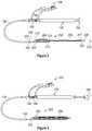
- FIG. 2is a side view of one embodiment of the thrombus extraction catheter having a thrombus extraction device is a deployed configuration.
- FIG. 3is a side view of one embodiment of the thrombus extraction catheter having a thrombus extraction device is a deployed configuration at full expansion.
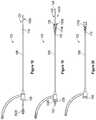
- FIG. 4is a side view of one embodiment of a self-expanding coring element.
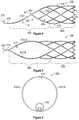
- FIG. 5is a top view of one embodiment of a self-expanding coring element.
- FIG. 6is a front view of one embodiment of a self-expanding coring element.
- FIG. 7is a side view of one embodiment of the thrombus extraction device in a full expansion configuration.
- FIG. 8is a view of one embodiment of a ball shaped thrombus captured in a thrombus extraction device.
- FIG. 9is a side view of one embodiment of the braided filament mesh structure having multiple pore sizes.
- FIG. 10is a side view of one embodiment of the thrombus extraction device including a plurality of circumferential grooves.
- FIG. 11is a schematic illustration of one embodiment of a weaving pattern for forming the cylindrical portion and/or the braided filament mesh structure onto the self-expanding coring element.
- FIG. 12is a section view of an embodiment of the handle with a plunger in a first position.
- FIG. 13is a section view of an embodiment of the handle with a plunger in a second position.
- FIG. 14is a close-up, section view of a portion of the handle with a plunger in a second position.
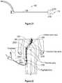
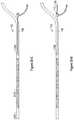
- FIG. 15is a side view of one embodiment of an obturator having a constant dimension of an elongate shaft.
- FIG. 16is a side view of one embodiment of an obturator having a variable dimension of an elongate shaft.
- FIG. 17is a detailed section view of one embodiment of the capture sheath of the obturator.
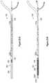
- FIG. 18is a side view of one embodiment of an introducer sheath in an undeployed configuration.
- FIG. 19is a side view of one embodiment of an introducer sheath in a partially deployed configuration.
- FIG. 20is a side view of one embodiment of an introducer sheath in a deployed configuration.
- FIG. 21is a side view of one embodiment of an introducer sheath comprising an inflatable balloon.
- FIG. 22is a schematic depiction of one embodiment of accessing the blood vessel via a popliteal access site.
- FIGS. 23 -A through 23 -Hare views depicting one embodiment of a process for fully expanding the thrombus extraction device in a blood vessel.
- FIGS. 24 -A and 24 -Bare views depicting alternative steps in the process for fully expanding the thrombus extraction device in a blood vessel.
- FIGS. 25 -A through 25 -Hare views depicting one embodiment of a process for removal of thrombus with an expanded thrombus extraction device.
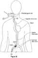
- FIG. 26is a schematic depiction of one embodiment of accessing the blood vessel via an internal jugular access site.
- FIG. 27is a schematic depiction of one embodiment of accessing the blood vessel via a popliteal access site with an extension sheath 2300 .
- FIG. 28is a schematic depiction of one embodiment of accessing the blood vessel via a popliteal access site and a femoral access site.
- the present disclosurerelates to a thrombectomy system for removal of a vascular thrombus from a blood vessel of a patient.
- the thrombectomy systemcan remove thrombus from a blood vessel, and particularly from a venous vessel of a patient via the coring of the thrombus and/or the separating of the thrombus from the walls of the blood vessel that can occur when the thrombectomy system is retracted through the vascular thrombus.
- Thrombus that is cored and/or separated from the walls of the blood vesselcan be captured within the thrombectomy system and removed from the patient.
- the thrombectomy systemcan include a thrombus extraction catheter including a Thrombus Extraction Device (“TED”).
- TEDcan include a proximal self-expanding coring element that can be a stent portion and/or that can be formed of a unitary fenestrated structure.
- the TEDcan include a distal expandable cylindrical portion formed of a braided filament mesh structure. The braided filament mesh structure can be formed on the coring element to thereby form a unitary TED.
- This forming of the braided filament mesh structure directly on the coring elementcan eliminate problems, such as: inconsistent material properties, decreased flexibility, decreased strength, and/or quality control issues, arising from connecting the braided filament mesh structure to the coring element via, for example, welding or adhesive.
- the expansion of the TEDcan be controlled by the relative movement of portions of the thrombus extraction catheter.
- a proximal end of the TED, and specifically a proximal end of the self-expanding coring elementcan be connected to an intermediate shaft that is slidable within an outer shaft of the thrombus extraction catheter.
- a distal end of the TED, and specifically a distal end of the expandable cylindrical portioncan be connected to an inner shaft that is slidable within the intermediate shaft of the thrombus extraction catheter.
- the TEDcan be withdrawn into the outer shaft to constrain the TED to an undeployed configuration, also referred to herein as a constrained configuration.
- the TEDcan be deployed from the outer shaft by the relative movement of the intermediate shaft with respect to the outer shaft.
- the inner shaft and the intermediate shaftcan be moved with respect to each other to either expand or contract the expandable cylindrical portion of the TED and to bring the self-expanding coring element to full expansion.
- the thrombectomy systemcan include an introducer sheath that can be sized to slidably receive the outer sheath of the thrombus extraction catheter.
- the introducer sheathcan include a sealed aperture at a proximal end of the introducer sheath and a self-expanding funnel.
- the self-expanding funnelcan be located at a distal end of the introducer sheath and can be selectably held in a constrained position by a capture sheath.
- the self-expanding funnelcan be slidably contained within the introducer sheath and can specifically be slidable with respect to the distal end of the introducer sheath.
- the self-expanding funnelcan be distally slide from a constrained configuration within the introducer sheath to a deployed configuration at which the self-expanding funnel extends from the distal end of the capture sheath.
- the self-expanding funnelcan be sized to engage with the self-expanding coring element when the TED is retracted towards the funnel.
- the funnelcompresses the TED, and specifically the coring element, and guides the TED, and specifically the coring element into a lumen defined by the introducer sheath.
- the TEDcan be retracted until it is completely contained within the introducer sheath, and then the TED and the thrombus captured in the TED can be removed from the patient via the sealed aperture.
- the thrombectomy systemcan access the blood vessel containing the thrombus via a plurality of access sites. These can include, for example, an internal jugular (IJ) access site, a femoral access site, a popliteal access site, or other venous or arterial access sites.
- IJinternal jugular
- the thrombectomy systemcan be used to extract thrombus and/or embolus from a variety of venous and/or arterial vessels, which can be peripheral vessels, including any vessel, including, by way of non-limiting example, a venous vessel, having a diameter of at least 5 millimeters (mm).
- the thrombectomy systemcan be inserted through an access point into a circulatory system of a patient and can be advanced to a position proximate to the thrombus.
- the TEDcan then be advanced through the thrombus, and, after being expanded distally of the thrombus, the TED can be retracted through the thrombus, thereby capturing all or portions of the thrombus.
- a thrombectomy system 100also referred to herein as a thrombus extraction system 100
- the thrombectomy system 100can be used to access a portion of a blood vessel such as a venous vessel containing thrombus and the thrombectomy system 100 can be used to remove all or portions of that thrombus from the blood vessel.
- the thrombectomy system 100can include an introducer sheath 102 and a thrombus extraction catheter 104 .
- the introducer sheath 102comprises an elongate member 106 , also referred to herein as an elongate sheath 106 , having a proximal end 108 and a distal end 110 .
- the elongate member 106can be elastic and/or flexible.
- the elongate member 106can comprise any desired length and any desired diameter.
- the elongate sheath 106can have an outer diameter of at least 10 French, at least 12 French, at least 14 French, at least 18 French, at least 20 French, at least 22 French, between 14 French and 24 French, between 15 French and 21 French, between 16 French and 22 French, and/or any other or intermediate size.
- the elongate member 106can comprise a radiopaque marker that can be, for example, part of the distal end 110 of the elongate member 106 .
- the elongate member 106defines a lumen extending between the proximal end 108 and the distal end 110 .
- the lumen 1701 (shown in FIG. 17 ) of the elongate member 106can be sized to slidably receive the thrombus extraction catheter 104 .
- the lumen 1701 of the elongate member 106can have an internal diameter of at least 2 French, at least 10 French, at least 14 French, at least 18 French, at least 20 French, at least 22 French, between 11 French and 12 French, between 10 French and 22 French, between 14 French and 21 French, between 16 French and 20 French, and/or any other or intermediate size.
- the lumen 1701can terminate at a sealed aperture 112 , also referred to herein as a sealed hub 112 , located at the proximal end 108 of the elongate member 106 .
- the sealed aperture 112can be self-sealing and/or can comprise a self-sealing seal.
- the introducer sheath 102can further include an aspiration port 114 that can be at the proximal end 108 of the elongate member 106 and/or connected to the proximal end 108 of the elongate member 106 via, for example, a connecting tube 116 .
- the aspiration port 114can be a part of, and/or connected to the sealed hub 112 .
- the aspiration port 114can be selectively fluidly connected to the lumen 1701 via, for example, a valve 118 , also referred to herein as an aspiration valve 118 , which valve 118 can be a tubing clamp that can be located at a position along the connecting tube 116 between the lumen 1701 and the aspiration port 114 .
- a valve 118also referred to herein as an aspiration valve 118
- valve 118can be a tubing clamp that can be located at a position along the connecting tube 116 between the lumen 1701 and the aspiration port 114 .
- the introducer sheath 102can further hold an obturator 120 , also referred to herein as a dilator 120 .
- the obturator 120can be configured to hold a self-expanding funnel that can be attached to the distal end 110 of the elongate member 106 in a constrained configuration, and to release the self-expanding funnel from that constrained configuration.
- the obturator 120can comprise a proximal end 122 , a distal end 124 , and an elongate shaft 126 extending therebetween.
- the elongate shaft 126can have a length that is greater than a length of the elongate member 106 of the introducer sheath 102 .
- the obturator 120can further define a lumen extending through the obturator 120 , which lumen can receive a guidewire.
- the guidewirecan comprise any desired dimensions and can, in some embodiments, have a diameter of approximately 0.035 inches.
- the obturator 120can be sized and shaped so as to be able to slidably move through the lumen of the elongate member 106 .
- the thrombectomy system 100can include the thrombus extraction catheter 104 .
- the thrombus extraction catheter 104can have a proximal end 130 and a distal end 132 .
- a handle 134also referred to herein as a deployment handle 134 , can be located at the proximal end 130 of the thrombus extraction catheter 104 and can connect to a catheter portion 136 , also referred to herein as the catheter 136 .
- the catheter 136can include an outer shaft 138 , an intermediate shaft 140 , and an inner shaft.
- the outer shaft 138can comprise a variety of lengths and sizes.
- the outer shaft 138can be sized to slidably fit within the introducer sheath 102 .
- the outer shaft 138can have a size of at least 8 French, at least 10 French, at least 11 French, at least 12 French, at least 14 French, at least 16 French, between 8 French and 14 French, between 11 French and 12 French, and/or any other or intermediate size.
- Each of the outer shaft 138 , the intermediate shaft 140 , and the inner shaftcan define a lumen that can be a central, axial lumen.
- the intermediate shaft 140can be sized and/or shaped to slidably fit within the lumen 802 (shown in FIG. 8 ) of the outer shaft 138 such that the intermediate shaft 140 and the outer shaft 138 are coaxial.
- the inner shaftcan be sized and/or shaped to slidably fit within the lumen 804 (shown in FIG. 8 ) of the intermediate shaft 140 such that the inner shaft and the intermediate shaft 140 are coaxial.
- each of the outer shaft 138 , the intermediate shaft 140 , and the inner shaftcan be displaced relative to the others of the outer shaft 138 , the intermediate shaft 140 , and the inner shaft.
- each of the outer shaft 138 , the intermediate shaft 140 , and the inner shaftcan have the same length, and in some embodiments some or all of the outer shaft 138 , the intermediate shaft 140 , and the inner shaft can have different lengths.
- the intermediate shaft 140can be relatively longer than the outer shaft 138
- the inner shaftcan be relatively longer than the intermediate shaft 140 .
- the thrombus extraction catheter 104can further include a thrombus extraction device (TED).
- TEDcan connect to the intermediate shaft 140 and the inner shaft, and can be contained in an undeployed configuration within the lumen 802 of the outer shaft 138 .
- the relative positioning of the outer shaft 138 , the intermediate shaft 140 , and/or the inner shaftcan result in the TED being in an undeployed configuration, a deployed configuration, a partial expansion configuration, and/or a full expansion configuration.
- the TED in the deployed configurationcan be in either the full expansion configuration or in the partial expansion configuration.
- the handle 134can include a distal end 142 , also referred to herein as a lock end 142 , and a proximal end 144 , also referred to herein as a plunger end 144 .
- the intermediate shaft 140connects to, and distally extends towards the distal end 132 of the thrombus extraction catheter 104 from the distal end 142 of the handle 134 .
- the distal end 142 of the handle 134can include a lock feature 146 such as, for example, a spinlock.
- the lock feature 146can selectively engage and/or lockingly engage with a mating feature 148 located on a proximal end 150 of the outer sheath 138 .
- the outer sheath 138can proximally slide over the intermediate sheath 140 until the lock feature 146 engages with the mating feature 148 to thereby secure the position of the outer sheath 138 with respect to the intermediate sheath 140 .
- a portion of the intermediate shaft 146distally extends from a distal end 152 of the outer shaft 138 when the outer shaft 138 is lockingly engaged with the lock feature 146 .
- the handle 134can include a plunger 154 that can be movable between a first, non-extended position and a second, extended position. In some embodiments, the plunger 154 can be moved from the first position to the second position by proximally displacing the plunger 154 relative to the handle 134 . The plunger 154 can be lockable in one or both of the first position and/or the second position.
- the plunger 154can connect to the inner shaft such that the inner shaft is displaceable relative to the handle 134 , the outer shaft 138 , and/or the intermediate shaft 140 via the movement of the plunger 154 from the first position to the second position.
- the inner shaftcan have a length such that the inner shaft distally extends past a distal end of the intermediate shaft 140 regardless of whether the plunger 154 is in the first position or the second position.
- the thrombus extraction catheter 104can further include a first flush port 155 connecting to the outer shaft 138 and a second flush port 156 connecting to the handle 134 .
- the first flush port 155can be fluidly connected to the lumen 802 of the outer shaft 138 so as to allow the flushing of the lumen 802 of the outer shaft 138 via the first flush port 155 .
- the second flush port 156can be fluidly connected to an internal portion of the handle 134 and thereby the lumen of the intermediate shaft 140 so as to allow the flushing of the lumen of the intermediate shaft 140 .
- the thrombectomy system 100can further include a loading funnel 158 .
- the loading funnel 158can include a funnel portion 160 and a shaft portion 162 .
- the funnel portion 160can define a funnel shaped interior volume connecting to a lumen of the shaft portion 162 .
- the funnel shaped interior volumecan be sized and shaped to receive the self-expanding funnel and to move the self-expanding funnel to a constrained position as the self-expanding funnel is advanced through the funnel portion 160 .
- the funnel shaped interior volume and the lumencan be sized to allow the distal end 124 of the obturator 120 to pass completely through the loading funnel 158 .
- the loading funnel 158can be configured to facilitate loading of the self-expanding funnel into the obturator 102 .
- the self-expanding funnelcan be loaded by inserting the obturator 120 through the elongate member 106 such that the obturator 120 extends from the distal end 110 of the elongate member 106 and beyond the self-expanding funnel.
- the loading funnel 158can then be proximally slid over the obturator 120 and the self-expanding funnel until the self-expanding funnel is fully encapsulated by the loading funnel 158 and/or until the self-expanding funnel is in the constrained configuration.
- the obturator 120can then be retracted to thereby load and/or capture the self-expanding funnel within a portion of the obturator 120 , and the loading funnel 158 can then be removed from the obturator 120 and the elongate member 106 .
- the thrombectomy system 100can further include a sealed hub dilator 170 , also referred to herein as a seal dilator 170 and/or an aperture dilator 170 .
- a section view of seal dilator 170is shown in FIG. 1 .
- the seal dilator 170can be sized and shaped for insertion into the sealed aperture 112 prior to removal of thrombus through the sealed aperture 112 . By this insertion into the sealed aperture 112 , the seal dilator 170 can dilate the sealed aperture 112 . In some embodiments, this dilation of the sealed aperture 112 can prevent the application of force from the sealed aperture 112 onto the thrombus during removal of the thrombus through the sealed aperture 112 .
- the seal dilator 170can comprise an insertion portion 172 configured to facilitate the insertion of the seal dilator 170 into the sealed aperture 112 .
- the seal dilator 170can further comprise a body portion 174 that can, alone, or together with the insertion portion 172 define an extraction lumen 176 through which the thrombus can be removed from the lumen 1701 of the elongate member 106 .
- the internal diameter of the extraction lumen 176can be larger than a diameter of the sealed aperture 112 in a sealed configuration
- the thrombus extraction catheter 104includes the handle 134 , the outer shaft 138 , the intermediate shaft 140 , the inner shaft 200 , and the thrombus extraction device 202 , also referred to herein as the TED 202 .
- the outer shaft 138is proximately displaced relative to the handle 134 such that the mating feature 148 of the outer shaft 138 is contacting the locking feature 146 of the handle 134 .
- each of the intermediate shaft 140 , the inner shaft 200 , and the TED 202distally extend beyond a distal end 204 of the outer shaft 138 .
- the thrombus extraction device 202 shown in FIG. 2is in a deployed and partial expansion configuration.
- the thrombus extraction device 202can include a self-expanding coring element 206 , and an expandable cylindrical portion 208 .
- the self-expanding coring element 206can be relatively more proximally located on the thrombus extraction catheter 104 than the expandable cylindrical portion 208 .
- the self-expanding coring element 206can include a proximal end 210 connecting to a distal end 212 of the intermediate shaft 140 and a distal end 214 connecting to a proximal end 216 of the expandable cylindrical portion 208 .
- the distal end 217 of the expandable cylindrical portion 208can connect to a distal end 218 of the inner shaft 200 .
- the distal end 218 of the inner shaft 200can further include a tip 220 such as an atraumatic tip and/or a radiopaque marker 222 .
- the tip 220can include the radiopaque marker 222 .
- Further radiopaque markerscan be located on, for example, the outer shaft 138 and specifically the distal end 204 of the outer shaft 138 and/or the distal end 212 of the intermediate shaft 140 .
- one or both of the distal end 204 of the outer shaft 138 and the distal end 212 of the intermediate shaft 140can each comprise a radiopaque marker.
- the atraumatic tip 220can define a channel configured to allow the guidewire to pass through the atraumatic tip 220 .
- FIG. 3a side view of one embodiment of the thrombus extraction catheter 104 with the thrombus extraction device 202 in the deployed and full expansion configuration is shown.
- the plunger 154is in the second position, proximally retracted from the handle 134 , and the inner shaft 200 is thereby proximally retracted relative to the intermediate shaft 140 to thereby fully expand the expandable cylindrical portion 208 and two secure the expandable cylindrical portion 208 and the self-expanding coring element 206 in full expansion configurations and/or in full expansion.
- the thrombus extraction catheter 104can comprise one or several features configured to secure the thrombus extraction device 202 , and specifically the self-expanding coring element 206 and/or the expandable cylindrical portion 208 in a fully expanded position and/or in full expansion.
- full expansionoccurs when the thrombus extraction device 202 is deployed and when the plunger 154 is in the second position.
- one or several dimensions of the thrombus extraction device 202can vary when the thrombus extraction device 202 is in full expansion. In some embodiments, this can facilitate apposition of the walls of the blood vessel by the thrombus extraction device 202 and/or a desired force or force level applied to the walls of the blood vessel by the thrombus extraction device 202 .
- the plunger 154can be locked in the second position by, for example, rotating the plunger 154 with respect to the handle 134 to thereby engage one or several locking features on the plunger 154 and in the handle 134 .
- the thrombus extraction device 202by locking the plunger 154 in the second position, the thrombus extraction device 202 , and specifically the self-expanding coring element 206 and/or the expandable cylindrical portion 208 can be secured in the full expansion by securing the position of the inner shaft 200 with respect to the intermediate shaft 140 .
- securing the position of the inner shaft 200 with respect to the intermediate shaft 140can include locking the inner shaft 200 with respect to the intermediate shaft 140 and/or coupling the position of the inner shaft 200 with respect to the position of the intermediate shaft 140 .
- this locking and/or couplingcan be static, referred to herein as statically locked and/or statically coupled, in that the position of the inner shaft 200 is fixed with respect to the position of the intermediate shaft 140 , and in some embodiments, this locking and/or coupling can be dynamic, referred to herein as dynamically locked and/or dynamically coupled, in that the position of the inner shaft 200 with respect to the intermediate shaft 140 is limited.
- the inner shaft 200can be dynamically locked to the plunger 154 via a compliance spring 1214 which allows some movement of the inner shaft 200 with respect to the intermediate shaft 140 when the plunger is locked in the second position.
- the inner shaft 200is dynamically locked and/or dynamically coupled to the intermediate shaft 140 and/or with respect to the intermediate shaft 140 .
- the self-expanding coring element 206can comprise a variety of shapes and sizes and can be made from a variety of materials.
- the self-expanding coring elementcan be made from a shape memory material such as, for example, a shape memory alloy and/or a shape memory polymer.
- the self-expanding coring element 206can comprise a nitinol and/or a nitinol alloy.
- the self-expanding coring element 206can be made using a variety of techniques including, for example, welding, laser welding, cutting, laser cutting, expanding, or the like.
- the self-expanding coring element 206can be laser cut from a piece of nitinol such as, for example, a nitinol tube, after which the self-expanding coring element 206 can be blown up and/or expanded.
- the self-expanding coring element 206can comprise a unitary fenestrated structure 400 and/or a stent or a stent portion that can be configured to core and separate a portion of a thrombus such as a vascular thrombus from the blood vessel containing the thrombus.
- This unitary fenestrated structure 400can comprise a plurality of struts 402 that together define a plurality of interstices 404 .
- the strutscan comprise a variety of shapes and sizes, and in some embodiments, the struts can have a thickness and/or diameter between approximately 0.05 and 0.15 inches, between approximately 0.075 and 0.125 inches, between approximately 0.09 and 0.1 inches, and/or of approximately 0.096 inches.
- the self-expanding coring element 206can comprise a first region 406 and a second region 408 .
- the second region 408can be generally tubular and can include a plurality of interconnected struts 402 .
- the first region 406as seen in FIG. 5 , can comprise a reduced number of struts 402 as compared to the second region to facilitate the collapse of the self-expanding coring element 206 to a non-expanded configuration and to maintain a coring orientation when the blood vessel is tortuous.
- the first regioncan further comprise two curved struts 410 -A, 410 -B twisting in opposite directions around a central axis 412 , also referred to herein as a longitudinal axis 412 , of the self-expanding coring element 206 to define a mouth 414 of the self-expanding coring element 206 .
- connection of the self-expanding coring element 206 to the intermediate shaft 140 via the two curved struts 410 -A, 410 -Bcan improve the operation of the thrombus extraction device 202 by flexibly connecting the self-expanding coring element 206 to the intermediate shaft 140 .
- the removal of struts from region 420 of the self-expanding coring element 206allows the self-expanding coring element 206 to flex about a connection member 415 located at the proximal end 210 of the self-expanding coring element 206 and connecting the self-expanding coring element 206 to the intermediate shaft 140 of the thrombus extraction catheter 104 .
- This ability to flexcan facilitate the maintenance of the coring orientation with the blood vessel is tortuous.
- such flexing of the self-expanding coring element 206can result in the region 420 functioning as the mouth 414 .
- the curved struts 410extend at an angle ⁇ , also referred to herein as a coring angle, relative to the central axis 412 from a bottom 416 of the self-expanding coring element 206 towards the top 418 of the self-expanding coring element 206 .
- this anglecan be between 20 degrees and 50 degrees and/or between 30 degrees and 45 degrees when fully expanded.
- the coring anglecan either positively or adversely affect the operation of the TED 202 .
- too steep a coring anglecan prevent the self-expanding coring element 206 from being collapsible and thus prevent the retraction of the self-expanding coring element 206 into the introducer sheath 102 .
- too shallow a coring anglecan result in the self-expanding coring element 206 too easily collapsing which can decrease the coring ability of the self-expanding coring element 206 .
- this decrease in the coring ability of the self-expanding coring element 206can result in the self-expanding coring element 206 no longer effectively coring thrombus.
- the most proximal edge of the two curved struts 410 -A, 410 -Bcan be sharpened and/or the leading edge 411 of the two curved struts 410 -A, 410 -B can comprise a cutting element, knife, or the like
- the self-expanding coring element 206can comprise a variety of sizes.
- the self-expanding coring element 206can comprise a length, defined as the shortest distance between the proximal end 210 of the self-expanding coring element 206 and the distal end 214 of the self-expanding coring element 206 , of between approximately one and 3 inches, between approximately 1.5 and 2.5 inches, between approximately 1.75 and 2.25 inches, between approximately 1.9 2.0 inches, and/or of approximately 1.96 inches.
- the self-expanding coring element 206can comprise a fully expanded diameter between approximately 2 and 50 mm, between approximately 4 and 25 mm, between approximately 6 and 20 mm, and/or between approximately 8 and 16 mm.
- the self-expanding coring elementcan be applied to debulking of an artery or vein such as, for example, the inferior vena cava.
- debulkingcan be performed in response to the occluding and/or partial occluding of one or several filters in the inferior vena cava.
- the length and the diameter of the self-expanding coring element 206can be selected based on the size of the blood vessel, and particularly the diameter of the blood vessel from which thrombus is to be extracted. In some embodiments, the length of the self-expanding coring element 206 can be selected based on the fully expanded diameter of the self-expanding coring element 206 to prevent undesired tipping and/or rotation of the self-expanding coring element within the blood vessel and with respect to the blood vessel. As used anywhere herein, “approximately” refers to a range of +/ ⁇ 10% of the value and/or range of values for which “approximately” is used.
- FIG. 7a side view of one embodiment of the thrombus extraction device 202 is shown.
- the self-expanding coring element 206is connected via the connection member 415 at the proximal end 210 of the self-expanding coring element 206 to the distal end 212 of the intermediate shaft 140 .
- the proximal end 216 of the expandable cylindrical portion 208connects to the distal end 214 of the self-expanding coring element 206 .
- the expandable cylindrical portion 208 and specifically the proximal end 216 of the expandable cylindrical portion 208is formed on the distal end 214 of the self-expanding coring element 206 to thereby form a unitary thrombus extraction device 202 .
- the distal end 217 of the expanding cylindrical portion 208connects to the distal end 218 of the inner shaft 200 .
- the self-expanding coring element 206can engage with all or portions of the inner shaft 200 to affect the expansion of the self-expanding coring element 206 .
- the self-expanding coring element 206can include a ring 700 , also referred to herein as a ring feature 700 .
- the ring 700can be the same material as the self-expanding coring element 206 or can be a different material than the self-expanding coring element 206 .
- the ring 700can be integrally formed with the self-expanding coring element 206 and/or can be attached to the self-expanding coring element via, for example, one or several welds, adhesive, one or several mechanical fasteners, or the like.
- the ring 700can have a diameter larger than the diameter of the inner shaft 200 such that the ring 700 is slidable along the inner shaft 200 .
- the inner shaft 200can include a stop 702 .
- the stop 702can comprise a polymeric member and/or metallic member that is affixed to a portion of the inner shaft 200 .
- the stop 702can be sized and shaped to engage with the ring 700 to thereby apply proximally directed force to the self-expanding coring element 206 when the inner shaft 200 is proximally displaced via movement of the plunger 154 to the second position.
- a portion of the self-expanding coring element 206 located between the ring 700 and the connection member 415can be forcibly expanded by the application of this proximally directed force to ring 700 , thereby moving the self-expanding coring member 206 to full expansion.
- the inner shaft 200 of the thrombus extraction catheter 104can be selectively connected to the distal end 217 of the expandable cylindrical portion 208 . This can allow the displacement of the inner shaft 200 to bring the self-expanding coring element 206 to full expansion via the engagement of the ring feature 700 with the stop 702 .
- the inner shaft 200can be recoupled to the distal end 217 of the expandable cylindrical portion 208 such that the expandable cylindrical portion 208 is fully expanded and/or can be recoupled to the distal end 217 of the expandable cylindrical portion 208 such that the expandable cylindrical portion 208 to compress the expandable cylindrical portion 208 when the plunger 154 is moved from the second position to the first position.
- the expandable cylindrical portion 208can comprise a braided filament mesh structure 704 that can be configured to capture thrombus.
- the braided filament mesh structurecan be coextensive with the expandable cylindrical portion 208 and thus can share a proximal end 216 and/or a distal end 217 .
- the braided filament mesh structure 704is a braid of elastic filaments having a generally tubular, elongated portion 706 and a distal tapered portion 708 .
- the braided filament mesh structure 704can be any porous structure and/or can have other suitable shapes, sizes, and configurations (e.g., the distal portion 708 can be generally cylindrical, etc.).
- the intermediate shaft 140is fixed and/or limited to axial movement at a rate less than that of the inner shaft 200 : (1) distal movement of the inner shaft 200 stretches the braided filament mesh structure 704 along its longitudinal axis such that the radius of the braided filament mesh structure 704 decreases and the length of the braided filament mesh structure 704 increases; and (2) proximal movement of the inner shaft 200 compresses the braided filament mesh structure 704 along its longitudinal axis such that the radius of the braided filament mesh structure 704 increases and the length of the braided filament mesh structure 704 decreases.
- the braided filament mesh structure 704can have a length in the collapsed configuration between approximately 5 and 30 inches, between approximately 10 and 20 inches, and/or of approximately 16 inches, and in some embodiments, the braided filament mesh structure 704 can have a length in the expanded configuration of between approximately 1 and 25 inches, between approximately 10 and 20 inches, and/or of approximately 11 inches.
- the braided filament mesh structure 704can be formed by a braiding machine and/or weaving machine, and in some embodiments, the braided filament mesh structure 704 can be manually braided and/or woven. In some embodiments, the braided filament mesh structure 704 may be formed as a tubular braid, which tubular braid may then be further shaped using a heat setting process. In some embodiments, the braid may be a tubular braid of fine metal wires such as nitinol (nickel-titanium alloy), platinum, cobalt-chrome alloy, stainless steel, tungsten or titanium. In some embodiments, the braided filament mesh structure 704 can be formed at least in part from a cylindrical braid of elastic filaments. Thus, the braid may be radially constrained without plastic deformation and will self-expand on release of the radial constraint. Such a braid of elastic filaments is herein referred to as a “self-expanding braid.”
- the thickness of the braid filamentscan be less that about 0.15 mm.
- the braidmay be fabricated from filaments and/or wires with diameters ranging from about 0.05 mm to about 0.25 mm.
- braid filaments of different diametersmay be combined to impart different characteristics including: stiffness, elasticity, structure, radial force, pore size, embolic capturing or filtering ability, etc.
- the braided filament countis between 20 and 80, is greater than 30, and/or is approximately 24.
- Pore sizes of the braided mesh in the elongated portion 706may be in the range of about 0.4 mm to 4.0 mm.
- the pore sizemay be in the range of 0.5 mm to 2.5 mm.
- thrombusmay form a shape that is difficult to retract into the introducer sheath 102 when thrombus is within the braided filament mesh structure 704 .
- FIG. 8Such a case is depicted in FIG. 8 in which the thrombus extraction device 202 , and specifically the braided filament mesh structure 704 , is partially retracted into the introducer sheath 102 .
- thrombus 800has formed a ball that has a diameter larger than the diameter of the introducer sheath 102 .
- FIGS. 9 and 10address features to prevent such behavior by the thrombus.
- FIG. 8further shows a cross-section view of the elongate member 106 such that the lumen 1702 of the elongate member is visible, a cross-section of the outer shaft 138 such that the lumen 802 of the outer shaft 138 is visible, and a cross-section of the intermediate shaft 140 such that the lumen 804 of the intermediate shaft 140 is visible.
- the braided filament mesh structure 704comprises a first portion 900 comprising a first plurality of pores 904 and a second portion 902 comprising a second plurality of pores 906 .
- the first portion 900can correspond to the elongated portion 706
- the second portion 902can correspond to the distal tapered portion 708 .
- the first portion 900 of the braided filament mesh structure 704is relatively more proximal than the second portion 902 .
- the pores in the first plurality of pores 904 of the first portion 900are smaller than the pores in the second plurality of pores 906 of the second portion 902 .
- the larger pores of the distal, second portion 902can have an average size greater than or equal to 1.5 mm, and in some embodiments, between approximately 1.0 mm and 4.0 mm.
- the larger size of the pores of the second plurality of pores 906can allow and/or facilitate the extrusion of portions of the thrombus when the braided filament mesh structure 704 is moved to the unexpanded configuration and/or when the braided filament mesh structure 704 is retracted into the introducer sheath 102 .
- this extrusion of portions of the thrombuscan prevent the case in which the thrombus cannot be retracted into the introducer sheath 102 .
- relatively newer portions of thrombuscan be extruded before relatively older portions of thrombus as relatively newer portions of thrombus can be softer and/or more malleable. These relatively newer portions of the thrombus can then be captured and/or broken down by features of the introducer sheath 102 .
- FIG. 10a side view of one embodiment of the TED 200 comprising a plurality of circumferential depressions 1000 , also referred to herein as circumferential grooves, radial ribs, and/or radial grooves, is shown.
- this plurality of circumferential depressions 1000can inwardly extend towards a central axis 1002 and/or midline 1002 of the thrombus extraction device 202 .
- the plurality of circumferential depressions 1000can be longitudinally spaced and/or equally spaced along the length of the expandable cylindrical portion 208 and/or the braided filament mesh structure 704 between the proximal end 216 and the distal end 217 of the cylindrical portion 208 and/or the braided filament mesh structure 704 .
- these circumferential depressions 1000can, when the thrombus extraction device 202 is moved from an expanded configuration to an unexpanded configuration, engage with portions of the thrombus contained within the cylindrical portion 208 and/or the braided filament mesh structure 704 to inhibit movement of the thrombus with respect to one or both of the proximal end 216 and the distal end 217 of the cylindrical portion 208 and/or the braided filament mesh structure 704 .
- This inhibition of thrombus movementcan decrease the likelihood of the creation of thrombus that cannot be retracted into the introducer sheath 102 .
- some embodiments of the thrombus extraction device 202can include both the plurality of circumferential depressions discussed with respect to FIG. 10 and multiple pore sizes as discussed with respect to FIG. 9 .
- the self-expanding coring element 206comprises a plurality of struts 402 that connect at formation points 1103 comprising peaks 1100 , also referred to herein as peak struts 1100 .
- each of the peaks 1100is formed by the intersection of a first strut 402 -A and a second strut 402 -B, which intersecting struts 402 -A, 402 -B form a peak aperture 1101 .
- the self-expanding coring element 206can comprise a plurality of peaks 1100 extending around the distal end of the self-expanding coring element 206 .
- the plurality of peaks 1100can comprise 4 peaks 1100 , 6 peaks 1100 , 8 peaks 1100 , 10 peaks 1100 , 12 peaks 1100 , 16 peaks 1100 , 20 peaks 1100 , 24 peaks 1100 , between 4 and 50 peaks, between 8 and 20 peaks, and/or any other or intermediate number of peaks.
- the cylindrical portion 208 and/or the braided filament mesh structure 704can comprise a plurality of filaments 1102 woven and/or braided together to form the cylindrical portion 208 and/or the braided filament mesh structure 704 .
- the plurality of filamentscan include, for each of the peaks 1100 of the self-expanding coring element 206 , a first filament 1104 and the second filament 1106 .
- the first and second filaments 1104 , 1106can be woven onto their respective peak.
- the first and second filaments 1104 , 1106can be woven onto their respective peak such that one or both of the first and second filaments 1104 , 1106 form a loop about their respective peak.
- the only the first filament 1104forms a look about its peak, only the second filament 1106 forms a loop about its peak, or both the first and second filaments 1104 , 1106 form loops about their peak.
- the first filament 1104can be inserted straight through the peak aperture 1101 of its peak such that the first filament 1104 does not loop on itself directly adjacent to its peak, and more specifically, directly distal of its peak.
- the first filament 1104can be inserted through the peak aperture 1101 of its peak 1100 such that the first filament 1104 passes, when looking from the outside of the self-expanding coring element 206 towards the inside of the self-expanding coring element 206 , on top of the first strut 402 -A and under the second strut 402 -B.
- the second filament 1106can be inserted through the peak aperture 1101 of its peak such that the portion of the second filament 1106 passing through the peak aperture 1101 is separated from the peak by the first filament 1104 . Further, the second filament 1106 can be inserted through the peak aperture 1101 such that the second filament 1106 passes underneath the first strut 402 -A and over the second strut 402 -B. after insertion through the peak aperture 1101 , the second filament 1106 can be looped on itself to form a loop 1108 directly distal to its peak 100 .
- each filament 1104 , 1106can be treated, for braiding or weaving purposes as comprising a first wire extending from its peak 1100 to a first end of the filament 1104 , 1106 and a second wire extending from its peak to a second end of that filament 1104 , 1106 .
- the cylindrical portion 208 and/or the braided filament mesh structure 704can be formed from 24 filaments 1104 , 1106 which can be woven and/or braided as 48 wires to form a 48 wire mesh and/or weave.
- the cylindrical portion 208 and/or the braided filament mesh structure 704can be braided/woven by, identifying the plurality of formation points 1103 formed by some of the struts 402 of the self-expanding coring element 206 .
- Unique pairs of wirescan be threaded through each of the formation points 1103 , and specifically through the peak aperture 1101 adjacent to each of the formation points 1103 .
- each unique pair of wirescan comprise a first wire 1104 and a second wire 1106 overlaying the first wire 1104 .
- the first and second wirescan then be woven into a net-like filament mesh structure of the cylindrical portion 208 and/or the braided filament mesh structure 704 from the unique pairs of wires such that the first wires 1104 do not form loops about the formation points 1103 through which the first wires 1104 are threaded and such that the second wires 1106 form loops 1108 about the formation points 1103 through which the second wires 1106 are threaded.
- the handle 134can include a housing 1200 that defines an internal volume 1202 .
- a plunger shaft 1204can extend through all or portions of the internal volume 1202 and can connect to the inner shaft 200 , which inner shaft 200 can define the previously referenced lumen 1400 , also referred to herein as inner shaft lumen 1400 .
- the plunger shaft 1204can terminate at a plunger guide 1208 that is affixed to the plunger shaft 1204 . In some embodiments, and as seen in FIGS.
- the plunger 154can be biased towards a first position by a plunger spring 1209 which can engage a portion of the handle 134 and the plunger guide 1208 .
- the plunger spring 1209is less compressed when the plunger 154 is in the first position as is shown in FIG. 12
- the plunger spring 1209is more compressed when the plunger 154 is in the second position as is shown in FIG. 13 .
- this bias towards the first positioncan create a bias in the thrombus extraction device 202 towards the partial expansion configuration.
- the plunger guide 1208can be positioned between a proximal stop 1210 and a distal stop 1212 , which proximal stop 1210 and which distal stop 1212 can be each affixed to the inner shaft 200 including the inner shaft lumen 1400 .
- the plunger guide 1208can be dynamically connected to the proximal stop 1210 via a stent compliance spring 1214 , also referred to herein as a compliance spring 1214 .
- the use of the compliance spring 1214 to connect the plunger guide 1208 and the proximal stop 1210can allow a change in the diameter of the self-expanding coring element 206 according to compressive forces applied to the self-expanding coring element 206 .
- radial compressive forces applied to the self-expanding coring element 206can be transferred from the self-expanding coring element 206 via the ring feature 700 and the stop 702 to the compliance spring 1214 .
- the compliance spring 1214can be compressed and the inner shaft 200 can distally advance relative to the intermediate shaft 140 to thereby reduce the diameter of the self-expanding coring element 206 until the compressive force is equal to the spring force.
- This compliance achieved via the compliance spring 1214enables use of the thrombus extraction catheter 104 in blood vessels that can be arteries or venous vessels of non-constant diameter while maintaining desired contact of the self-expanding coring element 206 on the walls of the blood vessels, veins, or venous vessels.
- this compliancecan result in a constant outward force applied to the vessel walls by the self-expanding coring element 206 when the vessel has a diameter between approximately 1 and 30 mm, 2 and 25 mm, 5 and 20 mm and/or any other or intermediate diameter.
- this constant outward forcecan be constant in that this outward force is within a predetermined range.
- the outward forcecan be approximately 5 N when the diameter of the self-expanding coring element 206 is approximately 20 mm and the outward force can be approximately 20 N when the diameter of the self-expanding coring element 206 is approximately 5 mm.
- a locking mechanismwhich can include the plunger 154 and the compliance spring 1214 can be configured to maintain a desired radial force on a vessel wall when the stent is compressed by that vessel wall. In some embodiments, this desired force can be a sufficient radial force on the vessel wall to core and/or separate all or portions of thrombus from the vessel wall when the self-expanding coring element 206 is at full expansion.
- the obturator 120includes the proximal end 122 , the distal end 124 , and the elongate shaft 126 .
- the obturator 120can include a capture sheath 1500 proximally extending form the distal end 124 of the obturator 120 .
- the Obturator 120can further comprise a tip such as an atraumatic tip 1502 located at the distal end 124 of the obturator 120 .
- the atraumatic tip 1502can be radiopaque.
- the obturator 120can further include a connection fitting 1504 that can be located at a proximal end 1506 of the capture sheath 1500 .
- the connection fitting 1504can be configured to sealingly connect with the distal end 110 of the elongate sheath 106 of the introducer sheath 102 .
- the obturator 120can further include a stop portion 1508 located at the proximal end 122 of the obturator 120 .
- the stop portion 1508can have a diameter larger than the lumen 1701 of the elongate member 106 of the introducer sheath 102 and/or larger than the diameter of the sealed aperture 112 located at the proximal end 108 of the introducer sheath 102 so as to prevent the stop portion 1508 from entering into the lumen 1701 of the elongate member 106 and/or the sealed aperture 112 .
- the elongate shaft 126can comprise a constant size and/or diameter, and in some embodiments, the elongate shaft 126 can comprise multiple sizes and/or diameters.
- the diameter 1510 of the elongate shaft 126 shown in FIG. 15is constant along the length of the elongate shaft 126 .
- the elongate shaft 126 shown in FIG. 16has at least a first diameter 1512 along one or several first portions 1513 of the elongate shaft 126 and a second diameter 1514 along one or several second portions 1515 of the elongate shaft 126 .
- the one or several second portions 1515 of the elongate shaftcan be located along the length of the elongate shaft 126 such, that when the obturator 120 is received within the elongate member 106 of the introducer sheath 102 and positioned so that the connection fitting 1504 seals with the distal end 110 of the elongate sheath 106 , the one or several second portions 1515 extend through the sealed aperture 112 .
- the second diameter 1514can be selected such that the one or several second portions do not contact and/or dilate the sealed aperture 112 and/or a seal within the sealed aperture 112 .
- the introducer sheath 102can be stored, package, and/or sold with such an obturator 120 pre-positioned extending through the lumen 1701 of the elongate member 106 .
- the capture sheath 1500includes the atraumatic tip 1502 and is connected to the elongate shaft 126 of the obturator 120 , which elongate shaft 126 extends through a lumen 1701 of the elongate member 106 .
- a lumen 1700extends through the atraumatic tip 1502 and the elongate shaft 126 , which lumen 1700 can be configured to receive a guidewire.
- That capture sheath 1500includes a capture shell 1702 that distally extends from the atraumatic tip 1502 to the proximal end 1506 of the capture sheath 1500 .
- the capture shell 1702terminates in the connection fitting 1504 .
- the capture shell 1702has an internal diameter 1704 that is greater than a diameter 1706 of the portion of the elongate shaft 126 extending through the capture shell 1702 . Due to the larger internal diameter 1704 of the capture shell 1500 , a receiving space is created between the capture shell 1702 and the portion of the elongate shaft 126 extending through the capture shell 1702 . In some embodiments, this receiving space can be sized and shaped to receive and/or retain a self-expanding funnel 1708 in a constrained configuration.
- the self-expanding funnel 1708can have a diameter matching the internal diameter 1704 of the capture shell 1702 when the self-expanding funnel 1708 is in the constrained configuration. In some embodiments, this diameter of the self-expanding funnel can be less than or equal to a diameter 1716 of the elongate member 106 .
- the self-expanding funnel 1708can comprise a variety of shapes and sizes and can be made from a variety of materials. In some embodiments, the self-expanding funnel 1708 can have a maximum diameter greater than and/or equal to the diameter of the self-expanded coring element 206 in full expansion, and in some embodiments, the self-expanding funnel 1708 can have a minimum diameter equal to the diameter 1716 of the elongate member 106 and/or to the diameter of the lumen 1701 of the elongate member 106 .
- the self-expanding funnel 1708can have a length greater than and/or equal to the length of the self-expanding coring element 206 such that the self-expanding coring element 206 can be received and contained within the self-expanding funnel 1708 .
- the self-expanding funnel 1708can have a conically shaped portion, and specifically, a truncated-conically shaped portion.
- the self-expanding funnelcan be formed from at least one of a castellated nitinol braid, a nitinol braided stent, a laser cut nitinol, a laser cut polymer tube, an injection molded polymeric structure, or an inflatable balloon.
- the self-expanding funnel 1708can comprise a mesh having a pore size sufficiently small to prevent the passage of dangerous thrombus through the pores of the mesh.
- the self-expanding funnel 1708can be permeable to blood.
- FIGS. 18 through 20side views of embodiments of the introducer sheath 102 in different configurations are shown.
- the introducer sheath 102is shown in an undeployed configuration
- FIG. 19the introducer sheath 102 is shown in a partially deployed configuration
- FIG. 20the introducer sheath 102 is shown in a fully deployed and/or deployed configuration.
- the obturator 120extends through the lumen 1701 of the elongate member 106 and the self-expanding funnel 1708 is contained in a constrained configuration within the capture sheath 1500 .
- the obturator 120has been distally advanced to thereby release the self-expanding funnel 1708 from the constrained configuration and/or to deploy the self-expanding funnel 1708 .
- the length of the obturator 120and specifically the length of the elongate shaft between the proximal end of the capture sheath 1500 and the stop portion 1508 is sufficient to allow the deployment of the self-expanding funnel 1708 from the capture sheath 1500 before further distal movement of the obturator 120 is prevented by the collision of the stop portion 1508 with the sealed aperture 112 .
- the obturator 120can be proximally retracted through the lumen 1701 of the elongate member 106 and the sealed aperture 112 and can be removed from the introducer sheath 102 . After the obturator 120 has been removed from the introducer sheath 102 , the introducer sheath is in the fully deployed configuration as shown in FIG. 20 .
- the introducer sheath 102can include an inflatable balloon 2100 located at, or proximate to the distal end 110 of the elongate member 106 .
- the balloon 2100can comprise a conically shaped internal portion 2102 that can be sized and shaped to receive the thrombus extraction device 202 , and specifically that can have a length greater than or equal to the length of the self-expanding coring element 206 .
- the thrombus 2200can be located in a blood vessel and accessed through an access site 2260 such as the popliteal access site.
- the introducer sheath 102can extend from the popliteal access site 2260 to the deployment position 2262 at which the self-expanding funnel 1708 can be deployed and which can be proximate to the thrombus 2200 .
- the TED 202can be passed through the clot 2200 in the direction of blood flow and the TED 202 can be retracted through the clot 2200 in a direction opposite blood flow. The retraction of the TED 202 through the clot 2200 can result in the coring of the clot with the self-expanding coring element 206 and the capturing of the clot in the expandable cylindrical 208 .
- all or portions of the TED 202can extend into one of the iliac veins and/or the inferior vena cava as depicted in FIG. 23 . Further, as the TED 202 is retracted from a proximal position with respect to the heart to a distal position with respect to the heart, the diameter of the blood vessel 2202 will decrease as the TED 202 is retracted towards the access site 2260 . This can result in increased compressive forces on the TED 202 , and specifically on the self-expanding coring element 206 . These compressive forces can be transferred via the ring feature 700 and the stop 702 to the compliance spring 1214 . Via the stretching or compressing of the compliance spring 1214 , the diameter of the TED 202 and specifically of the coring element 206 can change to match the diameter of the blood vessel and a desired radial force, and/or force level can be maintained.
- FIGS. 23 -A to 23 -H, FIGS. 24 -A and 24 -B, and FIGS. 25 -A to 25 -Hdepict processes for using the thrombus extraction system 100 to remove thrombus from a patient's body, and specifically from a blood vessel, which can be a venous vessel, in the patient's body.
- these one or several access sitescan include, for example, a popliteal access site, a femoral access site, and/or an internal jugular access site.
- a thrombolytic agentcan be infused and/or aspirated into or from the blood vessel before, during, or after the removal or extraction of the thrombus
- the process for using the thrombus extraction system 100 shown in FIGS. 22 -A to 22 -H, FIGS. 24 -A and 24 -B, and FIGS. 25 -A to 25 -Hcan be performed with the direction of blood flow or against the direction of blood flow.
- the direction of blood flow in FIGS. 22 -A to 22 -H, FIGS. 24 -A and 24 -B, and FIGS. 25 -A to 25 -Hcan be from left to right, or from right to left.
- a process for expanding the thrombus extraction device 202 in a blood vesselsuch as a venous vessel is shown.
- the process for expanding the thrombus extraction device 202 in the vesselcan be performed using all or portions of the thrombus extraction system 100 .
- the process for expanding the thrombus extraction device 202 in the vesselcan be performed in connection with a monitoring technique, such as fluoroscopy, angiography, and/or ultrasonic monitoring.
- the monitoring techniquecan be used to monitor the deployment of the TED 202 in the vessel via observation of the one or several radiopaque markers located on the introducer sheath 102 and/or the thrombus extraction catheter 104 .
- a thrombus 2200is identified in a blood vessel 2202 such as venous vessel.
- the thrombus 2200can be located in the peripheral vasculature of the patient's body.
- the thrombus 2200also referred to herein as a clot 2200 , can comprise a proximal end 2204 and the distal end 2206 .
- the identification of the blood vessel 2202can further include the determination of whether the thrombus 2200 in the blood vessel 2202 is suitable for thrombus extraction.
- the thrombus 2200 in the blood vessel 2202can be suitable for extraction when the blood vessel 2202 has a diameter of at least 5 millimeters. In some embodiments, the thrombus 2200 in the blood vessel 2202 can be suitable for extraction when the blood vessel 2202 has a diameter of at least 5 millimeters and is at least one of a femoral vein, an iliac vein, a popliteal vein, a posterior tibial vein, an anterior tibial vein, or a peroneal vein.
- the processproceeds to the step shown in FIG. 23 -B, wherein the introducer sheath 102 is advanced, either with or against the direction of blood flow in the blood vessel, such that the distal end 110 of the introducer sheath 102 and/or the obturator 120 is proximate to the thrombus 2200 , and particularly is proximate to the thrombus 2200 at a position proximal of the thrombus 2200 .
- thiscan include providing the introducer sheath 102 and percutaneously accessing the circulatory system of the patient and specifically a blood vessel or venous vessel of the patient via an access site 2208 which can be one of the above referenced access sites.
- the self-expanding funnel 1708can be deployed and/or unsheathed from the constrained configuration to the expanded configuration as depicted in FIG. 23 -C.
- the self-expanding funnel 1708can be deployed by the relative distal movement of the obturator 120 with respect to the elongate member 106 until the funnel 1708 is no longer constrained by the capture sheath 1500 and then the obturator 120 can be proximally retracted through the lumen 1701 of the elongate member 106 until the obturator 120 is removed from the introducer sheath 102 .
- the relative distal movement of the obturator 120 with respect to the elongate membercan comprise fixing the position of the obturator 120 relative to the blood vessel 2202 and proximally retracting the elongate member 106 over the obturator 120 to unsheathe the self-expanding funnel 1708 until the stop 1508 contacts the sealed aperture 112 and/or until monitoring, which can be fluoroscopic monitoring, of radiopaque markers located in, for example, the tip 1502 of the obturator 120 and the distal end 110 of the elongate member 106 indicate that the self-expanding funnel 1708 is deployed and/or is no longer constrained by the capture sheath 1500 .
- the relative distal movement of the obturator 120 with respect to the elongate membercan comprise fixing the position of the elongate member 106 relative to the blood vessel 2202 and distally advancing the obturator 120 two unsheathe the self-expanding funnel 1708 until the stop 1508 contacts the sealed aperture 112 and/or until monitoring, which can be fluoroscopic monitoring, of radiopaque markers located in, for example, the tip 1502 of the obturator 120 and the distal end 110 of the elongate member 106 indicate that the self-expanding funnel 1708 is deployed and/or is no longer constrained by the capture sheath 1500 .
- a portion of the thrombus extraction catheter 104such as the outer shaft 138 can be inserted into the lumen 1701 of the introducer sheath 102 via the sealed aperture 112 as depicted in FIG. 23 -D.
- thiscan include providing the thrombus extraction catheter 104 which comprises the thrombus extraction device 202 .
- the thrombus extraction device 202can be constrained within the outer shaft 138 and can inserted, together with the outer shaft 138 , into the lumen of the elongate member 106 via the sealed aperture 112 .
- the outer shaft 138 of the thrombus extraction catheter 104can have a diameter so as to dilate the seal of the sealed aperture 112 such that the sealed aperture 112 seals around and seals to the outer shaft 138 .
- a portion of the thrombus extraction catheter 104can be inserted via the introducer sheath 102 into the blood vessel 2202 as depicted in FIG. 23 -E.
- the distal end 132 of the thrombus extraction catheter 104can be advanced to a position proximate to the thrombus 2200 and/or to a position proximal to the thrombus 2200 .
- the insertion and/or advance of the thrombus extraction catheter 104can be monitored and specifically can be fluoroscopically monitored.
- the position of one or several radiopaque markers, including radiopaque marker 222 of the thrombus extraction catheter 104can be monitored.
- a portion of the thrombus extraction catheter 104can be distally advanced through the clot 2200 as depicted in FIG. 23 -F. In some embodiments, this distal advance through the clot 2200 can be either with or against the direction of blood flow. In some embodiments, the portion of the thrombus extraction catheter 104 distally advanced through the clot 2000 can contain and/or constrain the thrombus extraction device 202 .
- distally advancing the portion of the thrombus extraction catheter 104 through the clotcan include advancing the portion of the thrombus extraction catheter 104 until the radiopaque marker 222 , that can be fluoroscopically monitored and that can be located at the distal end 218 of the inner shaft 200 , is distally past the thrombus 2200 and/or a portion of the thrombus 2200 .
- the thrombus extraction device 202can be deployed as depicted in FIG. 23 -G.
- the thrombus extraction device 202can be deployed by either advancing the thrombus extraction device 202 beyond the distal end 204 of the outer shaft 138 or by retracting the outer shaft 138 relative to the thrombus extraction device 202 until the thrombus extraction device 202 is beyond the distal end 204 of the outer shaft 138 .
- the thrombus extraction devicecan be deployed such that the thrombus extraction device 202 is distally past the thrombus 2200 and/or distally past a desired portion of the thrombus 2200 .
- the thrombus extraction deviceis advanced beyond the distal end 204 of the outer shaft 138 by distally advancing the intermediate shaft 140 with respect to the outer shaft 138 .
- the intermediate shaft 140can be distally advanced until the lock feature 146 contacts the mating feature 148 , and the lock feature 146 can be mated and/or secured to the mating feature 148 to fix the relative position of the intermediate shaft 140 with respect to the outer shaft 138 .
- the deployment of the thrombus extraction device 202can be monitored, and specifically, the deployment of the thrombus extraction device 202 can be fluoroscopically monitored via, for example, the radiopaque marker 222 and the radiopaque marker located at one or both of the distal end 204 of the outer sheath 138 and the distal end 212 of the intermediate sheath 140 .
- the deployment of the thrombus extraction device 202and specifically the advancing of the thrombus extraction device 202 beyond the distal end 204 of the outer shaft 138 or retracting the outer shaft 138 relative to the thrombus extraction device 202 can be ceased based on a position the distal end 204 of the outer sheath 138 comprising the radiopaque marker (first radiopaque marker) relative to the radiopaque marker 222 located on the thrombus extraction device 202 (second radiopaque marker).
- first radiopaque markerfirst radiopaque marker
- the thrombus extraction device 202can be fully expanded as shown in FIG. 23 -H. In some embodiments, this can include allowing the full expansion of the thrombus extraction device 202 such that the thrombus extraction device 202 engages a wall 2220 of the blood vessel 2202 . In some embodiments, the thrombus extraction device 202 can be fully expanded by moving the plunger 154 from the first position to the second position and securing the plunger 154 in the second position to thereby fix the relative position of the inner shaft 200 with respect to the intermediate shaft 140 .
- the movement of the plunger 154 from the first position to the second positionproximally retracts the inner shaft 200 with respect to the intermediate shaft 140 to thereby fully expand the expandable cylindrical portion 208 of the thrombus extraction device 202 .
- the proximal retraction of the inner shaft 200 with respect to the intermediate shaft 140can further bring the stop 702 into engagement with the ring feature 700 to thereby fully expand the self-expanding coring element 206 .
- the securing of the plunger 154 in the second positioncan secure the self-expanding coring element 206 and the thrombus extraction device 202 in full expansion via the engagement of the stop 702 with the ring feature 700 .
- FIGS. 24 -A and 24 -Balternative embodiments of the steps shown in FIGS. 23 -G and 23 -H are shown.
- these alternative embodimentscan be performed when the diameter of the blood vessel 2202 containing the thrombus 2200 decreases below a desired level distally beyond the thrombus 2200 .
- the diameter of the blood vessel 2202can decrease. In some embodiments, this diameter can decrease to a point that use of the thrombus extraction device 202 may no longer be possible.
- an extension sheath 2300can be percutaneously inserted into the blood vessel 2202 through the wall 2220 of the blood vessel 2202 such that at least a portion of the extension sheath 2300 extends from the patient.
- the extension sheath 2300can be percutaneously inserted into the blood vessel 2202 at a position before the blood vessel diameter decreases below a desired value such as, for example, below 1 mm, 2 mm, 3 mm, 4 mm, 5 mm, 6 mm, 8 mm, 10 mm, or any other or intermediate value.
- the extension sheath 2300can be inserted into the blood vessel 2202 via an access site such as, for example, the popliteal access site.
- the thrombus extraction device 202can be deployed as depicted in FIG. 24 -A.
- the thrombus extraction device 202can be deployed by either advancing the thrombus extraction device 202 beyond the distal end 204 of the outer shaft 138 and into the extension sheath 2300 or by advancing the outer shaft 138 containing the thrombus extraction device 202 into the extension sheath and then retracting the outer shaft 138 relative to the thrombus extraction device 202 until the thrombus extraction device 202 is beyond the distal end 204 of the outer shaft 138 .
- the thrombus extraction devicecan be deployed such that the thrombus extraction device 202 is distally past the thrombus 2200 and/or distally past a desired portion of the thrombus 2200 . In some embodiments, all or portions of the thrombus extraction device can be contained within the extension sheath 2300 .
- the outer shaft 138 of the thrombus extraction catheter 104can be separable into a first piece and a second piece. In some embodiments, this separation can occur at a separation point that can comprise, for example, any feature configured to allow separation of the first and second pieces. These features can include a partial depth slit or score in the outer shaft 138 , an overlapping friction fit in the outer shaft 138 , or the like.
- the separable outer shaft 138can be used in the place of the extension sheath 2300 . In such an embodiment, the outer shaft 138 can exit the blood vessel 2202 via the access site such that the separable portion extends from inside the blood vessel 2202 to outside of the patient's body at the access point.
- the separation portion of the outer sheath 138can serve as the extension sheath 2300 and can remain in the access point when the thrombus extraction device 202 is retracted.
- the thrombus extraction device 202can be deployed by securing the position of the separation portion of the outer sheath 138 and retracting the thrombus extraction device 202 from that separation portion of the outer sheath 138 .
- the thrombus extraction devicecan be advanced beyond the distal end 204 of the outer shaft 138 by distally advancing the intermediate shaft 140 with respect to the outer shaft 138 .
- the intermediate shaft 140can be distally advanced until the lock feature 146 contacts the mating feature 148 .
- the lock feature 146can be mated and/or secured to the mating feature 148 to fix the relative position of the intermediate shaft 140 with respect to the outer shaft 138 .
- the deployment of the thrombus extraction device 202can be fluoroscopically monitored, and specifically, the deployment of the thrombus extraction device 202 can be fluoroscopically monitored via, for example, the radiopaque marker 222 and the radiopaque marker located at one or both of the distal end 204 of the outer sheath 138 and the distal end 212 of the intermediate sheath 140 .
- the deployment of the thrombus extraction device 202and specifically the advancing of the thrombus extraction device 202 beyond the distal end 204 of the outer shaft 138 or retracting the outer shaft 138 relative to the thrombus extraction device 202 can be seized based on a position the distal end 204 of the outer sheath 138 comprising the radiopaque marker (first radiopaque marker) relative to the radiopaque marker 222 located on the thrombus extraction device 202 (second radiopaque marker).
- first radiopaque markerfirst radiopaque marker
- the thrombus extraction device 202can be fully expanded as shown in FIG. 24 -B. in some embodiments, the thrombus extraction device 202 can be fully expanded while all or portions of the thrombus extraction device 202 are contained in the extension sheath 2300 . In such an embodiment, the portions of the thrombus extraction device 202 contained in the extension sheath 2300 can be prevented from reaching full expansion by the extension sheath 2300 . In such an embodiment, the thrombus extraction device 202 can reach full expansion as the thrombus extraction device is proximately retrieved from the extension sheath 2300 .
- the full expansion of the thrombus extraction device 202can include allowing the expansion of the thrombus extraction device 202 such that the thrombus extraction device 202 engages a wall 2220 of the blood vessel 2202 .
- the thrombus extraction device 202can be fully expanded by moving the plunger 154 from the first position to the second position and securing the plunger 154 in the second position to thereby fix the relative position of the inner shaft 200 with respect to the intermediate shaft 140 .
- the movement of the plunger 154 from the first position to the second positioncan proximally retract the inner shaft 200 with respect to the intermediate shaft 140 to thereby expand the expandable cylindrical portion 208 of the thrombus extraction device 202 .
- the proximal retraction of the inner shaft 200 with respect to the intermediate shaft 140can further bring the stop 702 into engagement with the ring feature 700 to thereby fully expand the self-expanding coring element 206 .
- the securing of the plunger 154 in the second positioncan secure the self-expanding coring element 206 and the thrombus extraction device 202 in full expansion via the engagement of the stop 702 with the ring feature 700
- the TED 202in which the TED 202 is all or wholly contained within the extension sheath 2300 , the TED 202 can be retracted until the self-expanding coring element 206 is outside of the extension sheath 2300 , and which point the inner shaft 200 can be decoupled from the distal end 217 of the expandable cylindrical portion 208 and the plunger 154 can be moved from the first position to the second position to bring the self-expanding coring element 206 to full expansion.
- the TED 202can then be further retracted and the expandable cylindrical portion 208 can be expanded by progressively recoupling the distal end 217 of the expandable cylindrical portion 208 with the inner shaft 200 as the expandable cylindrical portion 208 exits the extension sheath 2300 until the expandable cylindrical portion 208 has completely exited the extension sheath 2300 and is at full expansion with the distal end 217 of the expandable cylindrical portion 208 recoupled to the inner shaft 140 .
- the distal end 217 of the expandable cylindrical portion 208can remain uncoupled to the inner shaft 140 until the expandable cylindrical portion 208 has completely exited the extension sheath 2300 .
- the distal end 217 of the expandable cylindrical portion 208can be recoupled to the inner shaft 200 and the expandable cylindrical portion 208 can be expanded to full expansion.
- the thrombus 2200can be removed via the capture of the thrombus in the thrombus extraction device 202 via the proximal retraction of the thrombus extraction device 202 through the thrombus 2200 , which proximal retraction of the thrombus extraction device 202 can be, for example, in a direction of blood flow through the blood vessel 2202 or against the direction of blood flow through the vessel 2202 .
- the proximal retraction of the thrombus extraction device 202 through the thrombus 2200can result in the capture of the distal end 2206 of the thrombus 2200 before the capture of the proximal end 2204 of the thrombus 2200 .
- the proximal retraction of the thrombus extraction device 202can result in the separation and/or coring of at least a portion of the thrombus 2200 from the wall 2220 of the blood vessel 2202 by, for example, the self-expanding coring element 206 and/or the stent portion, and the capture of that separated portion of the thrombus 2200 within the expandable cylindrical portion 208 .
- the expandable cylindrical portion 208can be formed of the braided filament mesh structure that can be, for example, a net-like filament mesh structure.
- a portion of the thrombuscan be captured within the expandable cylindrical portion 208 by entering the expandable cylindrical portion 208 via the mouth 414 of the self-expanding coring element 206 and/or via one or several of the interstices 404 of the self-expanding coring element 206 .
- the distal end 2206 of the thrombus 2200is separated and/or cored from the walls 2220 of the blood vessel 2202 by the self-expanding coring element 206 via the proximal retraction of the thrombus extraction device 202 .
- the distal end 2206 of the thrombus 2200is captured in the expandable cylindrical portion 208 of the thrombus extraction device by the continued proximal retraction of the thrombus extraction device through the thrombus 2200 .
- FIGS. 25 -C, 25 -D, and 25 -EThe separation and capture and/or coring and capture of further portions of the thrombus 2200 by the continued proximal retraction of the thrombus extraction device 202 is shown in FIGS. 25 -C, 25 -D, and 25 -E.
- the proximal end 2204 of the thrombus 2200is cored and captured as the thrombus extraction device 202 is proximally retracted towards the self-expanding funnel 1708 .
- the thrombus extraction device 202can be proximally retracted until a portion of the self-expanding coring element 206 is contained within the self-expanding funnel 1708 as seen in FIG. 25 -F, and specifically until the mouth 414 of the self-expanding coring element 206 is contained within the self-expanding funnel 1708 .
- the containment of the mouth 414 within the self-expanding funnel 1708can be fluoroscopically verified.
- the mouth 414can be determined as wholly contained within the self-expanding funnel 1708 via fluoroscopic monitoring based on the alignment/relative positioning of the distal end 212 of the intermediate shaft 140 comprising a radiopaque marker 2450 and/or the radiopaque marker 222 with respect to the distal end 110 comprising a radiopaque marker 2452 of the elongate member 106 of the introducer sheath 102 .
- the plunger 154can be unlocked from the second position and can be moved from the second position to the first position to thereby move the thrombus extraction device 202 from and expanded configuration to an unexpanded configuration.
- the unlocking of the plunger 154 from the second positioncan unlock and/or decouple the inner shaft 200 with respect to the intermediate shaft 140 , and the moving of the plunger 154 from the second position to the first position can cause the distal advancing of the inner shaft 200 relative to the intermediate shaft 140 .
- the thrombus extraction device 202can be collapsed by moving the thrombus extraction device 202 from the expanded configuration to the unexpanded configuration prior to withdrawing the thrombus extraction device 202 from the patient's body so as to compress the thrombus 2200 captured by the thrombus extraction device 202 .
- the compression of the thrombus 2200 by the thrombus extraction device 202can secure the position of the thrombus within the thrombus extraction device 202 via, in some embodiments, the engagement of one or several of the plurality of circumferential depressions 1000 with the thrombus 2200 .
- the thrombus extraction device 202can be proximally retracted through the self-expanding funnel 1708 and into the elongate member 106 as depicted in FIG. 25 -G.
- the collapse of the thrombus extraction device 202 and/or the retraction of the thrombus extraction device 202 into the self-expanding funnel 1708 and/or the elongate membercan result in the extrusion of all or portions of the thrombus 2200 through pores of the expandable cylindrical portion 208 of the thrombus extraction device 202 including, for example, some or all of the first plurality of pores 904 and/or the second plurality of pores 906 .
- the all or portions of the thrombus 2200can be extruded through some or all of the second plurality of pores 906 which can be larger than the first plurality of pores 904 .
- the pores in the second plurality of pores 906can be sized to be sufficiently small such that any thrombus portions of the thrombus 2200 extruded through the pores is sufficiently small to have little or no clinical significance.
- these extruded all or portions of the thrombus 2200can be captured by the self-expanding funnel 1708 .
- the thrombus extraction device 202can continue to be proximally retracted as depicted in FIG. 25 -H until the thrombus extraction device 202 and the captured thrombus 2200 is fully contained within the elongate member 106 .
- the seal dilator 170can be inserted into the sealed aperture 112 and the thrombus extraction device 202 and the captured thrombus 2200 can then be withdrawn or removed from the patient's body and from the elongate member 106 via the sealed aperture 112 in the seal dilator 170 .
- thrombus captured by the self-expanding funnel 1708can then either be guided into the elongate member 106 and specifically into the lumen 1701 of the elongate member 106 or further compressed and/or broken up by the self-expanding funnel 1708 and then allowed to pass through the self-expanding funnel 1708 , and particularly through the mesh of the self-expanding funnel 1708 .
- this thrombuscan be aspirated through the lumen 1701 of the elongate member 106 and the aspiration port 114 .
- the aspiration of the thrombus via the aspiration port 114can include the opening of the aspiration valve 118 .
- introduction techniques for accessing the thrombus 2200are shown.
- these introduction techniquescan allow the use of a larger sized introducer sheath 102 due to the larger size of the vessels in the path to the thrombus.
- this larger size of the introducer sheath 102can ease the removal of thrombus through the introducer sheath 102 as, in some embodiments, the size of the lumen 1701 of the introducer sheath 102 can increase as the size of the introducer sheath 102 increases.
- the user of a larger sized introducer sheath 102can allow the removal of larger thrombus.
- the lengths of the components of the thrombus extraction system 100and particularly the lengths of the introducer sheath 102 and the thrombus extraction catheter 104 can vary based on the selected technique for accessing the thrombus and/or based on the location of the thrombus.
- the introducer sheath 102can be inserted into the patient's body via an internal jugular access site 2500 .
- the introducer sheath 102can extend from the internal jugular access site 2500 to the deployment position 2502 which can be proximal to the thrombus 2200 .
- the self-expanding funnel 1708can be deployed at the deployment position 2502 .
- the introducer sheathcan extend from the internal jugular access site 2500 through the superior vena cava and the inferior vena cava to the deployment position 2502 in one of the common iliac veins.
- the deployment position 2502can be located in, for example, the inferior vena cava, one of the iliac veins, the femoral vein, the popliteal vein, before or beyond the iliac arch, or any other location proximate to and/or proximal to the thrombus 2200 .
- the use of the internal jugular access site 2500can allow for a larger diameter of the elongate member 106 .
- use of the internal jugular access site 2500can be combined with use of the extension sheath 2300 that can be inserted into the blood vessel 2202 at a popliteal access site 2600 .
- the thrombus extraction devicecan wholly or partially exit the patient's body while contained in the extension sheath 2300 before being retracted through the thrombus 2200 .
- the introducer sheathcan, in some embodiments, be inserted into the patient's body into an access site connected to the blood vessel 2202 containing the thrombus via the common iliac veins. In the specific embodiment shown in FIG. 28 , this can be achieved via insertion into the patient's body via a femoral access site 2700 . In some embodiments, use of an access site connected to the blood vessel 2202 via the common iliac veins, and specifically user of the femoral access site 2700 can be combined with user of the extension sheath 2300 that can be inserted into the blood vessel 2202 at a popliteal access site 2600 . In some such embodiments, the thrombus extraction device can wholly or partially exit the patient's body while contained in the extension sheath 2300 before being retracted through the thrombus 2200 .
Landscapes
- Health & Medical Sciences (AREA)
- Life Sciences & Earth Sciences (AREA)
- Surgery (AREA)
- Heart & Thoracic Surgery (AREA)
- Public Health (AREA)
- Vascular Medicine (AREA)
- Engineering & Computer Science (AREA)
- Biomedical Technology (AREA)
- Veterinary Medicine (AREA)
- General Health & Medical Sciences (AREA)
- Animal Behavior & Ethology (AREA)
- Molecular Biology (AREA)
- Medical Informatics (AREA)
- Nuclear Medicine, Radiotherapy & Molecular Imaging (AREA)
- Orthopedic Medicine & Surgery (AREA)
- Cardiology (AREA)
- Oral & Maxillofacial Surgery (AREA)
- Transplantation (AREA)
- Surgical Instruments (AREA)
Abstract
Description
Claims (19)
Priority Applications (1)
| Application Number | Priority Date | Filing Date | Title |
|---|---|---|---|
| US15/821,224US10524811B2 (en) | 2015-10-23 | 2017-11-22 | Intravascular treatment of vascular occlusion and associated devices, systems, and methods |
Applications Claiming Priority (4)
| Application Number | Priority Date | Filing Date | Title |
|---|---|---|---|
| US201562245935P | 2015-10-23 | 2015-10-23 | |
| US15/268,296US9700332B2 (en) | 2015-10-23 | 2016-09-16 | Intravascular treatment of vascular occlusion and associated devices, systems, and methods |
| US15/614,426US9844387B2 (en) | 2015-10-23 | 2017-06-05 | Intravascular treatment of vascular occlusion and associated devices, systems, and methods |
| US15/821,224US10524811B2 (en) | 2015-10-23 | 2017-11-22 | Intravascular treatment of vascular occlusion and associated devices, systems, and methods |
Related Parent Applications (1)
| Application Number | Title | Priority Date | Filing Date |
|---|---|---|---|
| US15/614,426ContinuationUS9844387B2 (en) | 2015-10-23 | 2017-06-05 | Intravascular treatment of vascular occlusion and associated devices, systems, and methods |
Publications (2)
| Publication Number | Publication Date |
|---|---|
| US20180092652A1 US20180092652A1 (en) | 2018-04-05 |
| US10524811B2true US10524811B2 (en) | 2020-01-07 |
Family
ID=58561858
Family Applications (3)
| Application Number | Title | Priority Date | Filing Date |
|---|---|---|---|
| US15/268,296ActiveUS9700332B2 (en) | 2015-10-23 | 2016-09-16 | Intravascular treatment of vascular occlusion and associated devices, systems, and methods |
| US15/614,426ActiveUS9844387B2 (en) | 2015-10-23 | 2017-06-05 | Intravascular treatment of vascular occlusion and associated devices, systems, and methods |
| US15/821,224Active2037-05-18US10524811B2 (en) | 2015-10-23 | 2017-11-22 | Intravascular treatment of vascular occlusion and associated devices, systems, and methods |
Family Applications Before (2)
| Application Number | Title | Priority Date | Filing Date |
|---|---|---|---|
| US15/268,296ActiveUS9700332B2 (en) | 2015-10-23 | 2016-09-16 | Intravascular treatment of vascular occlusion and associated devices, systems, and methods |
| US15/614,426ActiveUS9844387B2 (en) | 2015-10-23 | 2017-06-05 | Intravascular treatment of vascular occlusion and associated devices, systems, and methods |
Country Status (1)
| Country | Link |
|---|---|
| US (3) | US9700332B2 (en) |
Cited By (51)
| Publication number | Priority date | Publication date | Assignee | Title |
|---|---|---|---|---|
| US11147571B2 (en) | 2012-09-24 | 2021-10-19 | Inari Medical, Inc. | Device and method for treating vascular occlusion |
| US11154314B2 (en) | 2018-01-26 | 2021-10-26 | Inari Medical, Inc. | Single insertion delivery system for treating embolism and associated systems and methods |
| EP3973895A1 (en)* | 2020-09-23 | 2022-03-30 | Neuravi Limited | Rotating frame thrombectomy device |
| US11382643B2 (en) | 2017-10-16 | 2022-07-12 | Retriever Medical, Inc. | Clot removal methods and devices with multiple independently controllable elements |
| US11395669B2 (en) | 2020-06-23 | 2022-07-26 | Neuravi Limited | Clot retrieval device with flexible collapsible frame |
| US11406416B2 (en) | 2018-10-02 | 2022-08-09 | Neuravi Limited | Joint assembly for vasculature obstruction capture device |
| US11433218B2 (en) | 2015-12-18 | 2022-09-06 | Inari Medical, Inc. | Catheter shaft and associated devices, systems, and methods |
| US11439418B2 (en) | 2020-06-23 | 2022-09-13 | Neuravi Limited | Clot retrieval device for removing clot from a blood vessel |
| US11517340B2 (en) | 2019-12-03 | 2022-12-06 | Neuravi Limited | Stentriever devices for removing an occlusive clot from a vessel and methods thereof |
| US11529158B2 (en) | 2004-03-25 | 2022-12-20 | Inari Medical, Inc. | Method for treating vascular occlusion |
| US11529157B2 (en) | 2008-07-22 | 2022-12-20 | Neuravi Limited | Clot capture systems and associated methods |
| US11547427B2 (en) | 2013-03-14 | 2023-01-10 | Neuravi Limited | Clot retrieval devices |
| US11554005B2 (en) | 2018-08-13 | 2023-01-17 | Inari Medical, Inc. | System for treating embolism and associated devices and methods |
| US11589880B2 (en) | 2007-12-20 | 2023-02-28 | Angiodynamics, Inc. | System and methods for removing undesirable material within a circulatory system utilizing during a surgical procedure |
| US11589881B2 (en) | 2017-10-16 | 2023-02-28 | Retriever Medical, Inc. | Clot removal methods and devices with multiple independently controllable elements |
| US11633202B1 (en) | 2017-10-16 | 2023-04-25 | Retriever Medical, Inc. | Catheter based retrieval device with proximal body having axial freedom of movement |
| US11648020B2 (en) | 2020-02-07 | 2023-05-16 | Angiodynamics, Inc. | Device and method for manual aspiration and removal of an undesirable material |
| US11648028B2 (en) | 2012-11-20 | 2023-05-16 | Inari Medical, Inc. | Methods and apparatus for treating embolism |
| US11679194B2 (en) | 2021-04-27 | 2023-06-20 | Contego Medical, Inc. | Thrombus aspiration system and methods for controlling blood loss |
| US11697011B2 (en) | 2017-09-06 | 2023-07-11 | Inari Medical, Inc. | Hemostasis valves and methods of use |
| US11712256B2 (en) | 2014-11-26 | 2023-08-01 | Neuravi Limited | Clot retrieval device for removing occlusive clot from a blood vessel |
| US11712231B2 (en) | 2019-10-29 | 2023-08-01 | Neuravi Limited | Proximal locking assembly design for dual stent mechanical thrombectomy device |
| US11717308B2 (en) | 2020-04-17 | 2023-08-08 | Neuravi Limited | Clot retrieval device for removing heterogeneous clots from a blood vessel |
| US11730501B2 (en) | 2020-04-17 | 2023-08-22 | Neuravi Limited | Floating clot retrieval device for removing clots from a blood vessel |
| US11737771B2 (en) | 2020-06-18 | 2023-08-29 | Neuravi Limited | Dual channel thrombectomy device |
| US11806033B2 (en) | 2017-01-10 | 2023-11-07 | Inari Medical, Inc. | Devices and methods for treating vascular occlusion |
| US11839392B2 (en) | 2013-03-14 | 2023-12-12 | Neuravi Limited | Clot retrieval device for removing clot from a blood vessel |
| US11857210B2 (en) | 2014-11-26 | 2024-01-02 | Neuravi Limited | Clot retrieval device for removing clot from a blood vessel |
| US11864779B2 (en) | 2019-10-16 | 2024-01-09 | Inari Medical, Inc. | Systems, devices, and methods for treating vascular occlusions |
| US11871946B2 (en) | 2020-04-17 | 2024-01-16 | Neuravi Limited | Clot retrieval device for removing clot from a blood vessel |
| US11871949B2 (en) | 2010-10-22 | 2024-01-16 | Neuravi Limited | Clot engagement and removal system |
| US11896246B2 (en) | 2007-12-20 | 2024-02-13 | Angiodynamics, Inc. | Systems and methods for removing undesirable material within a circulatory system utilizing a balloon catheter |
| US11918243B2 (en) | 2015-10-23 | 2024-03-05 | Inari Medical, Inc. | Intravascular treatment of vascular occlusion and associated devices, systems, and methods |
| US11937837B2 (en) | 2020-12-29 | 2024-03-26 | Neuravi Limited | Fibrin rich / soft clot mechanical thrombectomy device |
| US11937836B2 (en) | 2020-06-22 | 2024-03-26 | Neuravi Limited | Clot retrieval system with expandable clot engaging framework |
| US11937838B2 (en) | 2013-10-21 | 2024-03-26 | Inari Medical, Inc. | Methods and apparatus for treating embolism |
| US11974764B2 (en) | 2021-06-04 | 2024-05-07 | Neuravi Limited | Self-orienting rotating stentriever pinching cells |
| US11980379B2 (en) | 2014-11-26 | 2024-05-14 | Neuravi Limited | Clot retrieval system for removing occlusive clot from a blood vessel |
| US11998223B2 (en) | 2011-03-09 | 2024-06-04 | Neuravi Limited | Clot retrieval device for removing a clot from a blood vessel |
| US12029442B2 (en) | 2021-01-14 | 2024-07-09 | Neuravi Limited | Systems and methods for a dual elongated member clot retrieval apparatus |
| US12064130B2 (en) | 2021-03-18 | 2024-08-20 | Neuravi Limited | Vascular obstruction retrieval device having sliding cages pinch mechanism |
| US12076037B2 (en) | 2011-03-09 | 2024-09-03 | Neuravi Limited | Systems and methods to restore perfusion to a vessel |
| US12133657B2 (en) | 2016-09-06 | 2024-11-05 | Neuravi Limited | Clot retrieval device for removing occlusive clot from a blood vessel |
| US12178467B2 (en) | 2011-03-15 | 2024-12-31 | Angiodynamics, Inc. | Device and method for removing material from a hollow anatomical structure |
| US12245788B2 (en) | 2011-03-15 | 2025-03-11 | Angiodynamics, Inc. | Device and method for removing material from a hollow anatomical structure |
| US12274844B2 (en) | 2019-06-24 | 2025-04-15 | Covidien Lp | Thrombus removal device |
| US12285182B2 (en) | 2018-10-10 | 2025-04-29 | Innova Vascular, Inc. | Devices and methods for removing an embolus |
| US12318097B2 (en) | 2007-12-20 | 2025-06-03 | Angiodynamics, Inc. | Systems and methods for removing undesirable material within a circulatory system |
| US12364496B2 (en) | 2022-01-11 | 2025-07-22 | Inari Medical, Inc. | Devices for removing clot material from intravascularly implanted devices, and associated systems and methods |
| US12390236B2 (en) | 2021-03-10 | 2025-08-19 | Covidien Lp | Thrombus removal device |
| US12402902B2 (en) | 2013-03-14 | 2025-09-02 | Neuravi Limited | Devices and methods for removal of acute blockages from blood vessels |
Families Citing this family (57)
| Publication number | Priority date | Publication date | Assignee | Title |
|---|---|---|---|---|
| US9827084B2 (en) | 2007-10-26 | 2017-11-28 | Embolitech, Llc | Intravascular guidewire filter system for pulmonary embolism protection and embolism removal or maceration |
| WO2015173646A1 (en) | 2014-05-16 | 2015-11-19 | Veosource Sa | Implantable self-cleaning blood filters |
| CN106470728A (en) | 2014-06-09 | 2017-03-01 | 因赛普特斯医学有限责任公司 | Retraction and suction device and related systems and methods for treating embolism |
| WO2016197351A1 (en) | 2015-06-11 | 2016-12-15 | Beijing Advanced Medical Technologies, Inc. | A close-cell structured stent, a preparation method and use thereof |
| CN108348319B (en) | 2015-09-28 | 2020-03-10 | 斯瑞克公司 | Mechanical embolectomy device and method |
| US9700332B2 (en)* | 2015-10-23 | 2017-07-11 | Inari Medical, Inc. | Intravascular treatment of vascular occlusion and associated devices, systems, and methods |
| US10342571B2 (en) | 2015-10-23 | 2019-07-09 | Inari Medical, Inc. | Intravascular treatment of vascular occlusion and associated devices, systems, and methods |
| CA3007660A1 (en) | 2015-12-15 | 2017-06-22 | Neovasc Tiara Inc. | Transseptal delivery system |
| JP6806791B2 (en)* | 2016-04-19 | 2021-01-06 | ジャイラス・エーシーエムアイ・インコーポレーテッド | Medical extraction device |
| EP3590446B1 (en) | 2016-04-25 | 2021-01-06 | Stryker Corporation | Anti-jamming and macerating thrombectomy apparatuses |
| WO2017189591A1 (en) | 2016-04-25 | 2017-11-02 | Stryker Corporation | Inverting mechanical thrombectomy apparatuses and methods of use in the vasculature |
| EP3448276B1 (en) | 2016-04-25 | 2020-03-04 | Stryker Corporation | Clot-engulfing mechanical thrombectomy apparatuses |
| US11497512B2 (en) | 2016-04-25 | 2022-11-15 | Stryker Corporation | Inverting thrombectomy apparatuses and methods |
| US11896247B2 (en) | 2016-04-25 | 2024-02-13 | Stryker Corporation | Inverting mechanical thrombectomy apparatuses |
| CN109561903B (en) | 2016-06-03 | 2021-07-27 | 斯瑞克公司 | Flip thrombectomy device |
| WO2018049317A1 (en) | 2016-09-12 | 2018-03-15 | Stryker Corporation | Self-rolling thrombectomy apparatuses and methods |
| US11197750B2 (en)* | 2016-11-29 | 2021-12-14 | Lake Region Manufacturing, Inc. | Embolic protection device |
| US9848906B1 (en)* | 2017-06-20 | 2017-12-26 | Joe Michael Eskridge | Stent retriever having an expandable fragment guard |
| US10736760B2 (en)* | 2017-09-26 | 2020-08-11 | Microvention, Inc. | Stent and stent connection interface |
| EP4176830A1 (en) | 2017-11-09 | 2023-05-10 | Stryker Corporation | Inverting thrombectomy apparatuses having enhanced tracking |
| US11490908B2 (en) | 2017-11-09 | 2022-11-08 | Contego Medical , Inc. | Thrombectomy device and methods of use |
| CN108143464A (en)* | 2018-01-19 | 2018-06-12 | 上海唯域医疗科技有限公司 | Thrombectomy Catheter and Thrombectomy for Thrombectomy Catheter |
| WO2019222117A1 (en) | 2018-05-14 | 2019-11-21 | Stryker Corporation | Inverting thrombectomy apparatuses and methods of use |
| EP3569200B1 (en)* | 2018-05-18 | 2024-12-04 | Eucatech AG | Tubular knitted stents |
| CN112969420B (en)* | 2018-09-10 | 2024-12-17 | 史赛克公司 | Inverted thrombectomy device and method of using thrombectomy device |
| CN112702961A (en) | 2018-09-10 | 2021-04-23 | 斯瑞克公司 | Laser grooving and grabbing device |
| EP3858290A4 (en)* | 2018-09-28 | 2021-10-20 | TERUMO Kabushiki Kaisha | Filter device |
| CN112888406B (en)* | 2018-10-08 | 2025-03-18 | 瑞弗罗医疗公司 | Delivery system for stents with prominent features |
| CN111358527A (en)* | 2018-12-26 | 2020-07-03 | 杭州唯强医疗科技有限公司 | thrombus capture system |
| KR20210126681A (en) | 2019-02-13 | 2021-10-20 | 엠볼린, 인크. | Catheter with integrated embolic protection |
| WO2020236752A1 (en)* | 2019-05-17 | 2020-11-26 | Veosource Sa | Self-cleaning aortic blood filter |
| US11779742B2 (en)* | 2019-05-20 | 2023-10-10 | Neovasc Tiara Inc. | Introducer with hemostasis mechanism |
| US20210052375A1 (en)* | 2019-08-19 | 2021-02-25 | Encompass Technologies, Inc. | Embolic protection access system |
| US11707351B2 (en) | 2019-08-19 | 2023-07-25 | Encompass Technologies, Inc. | Embolic protection and access system |
| US11911051B2 (en)* | 2019-10-31 | 2024-02-27 | Abbott Cardiovascular Systems Inc. | Dimpled joint for guidewire |
| US20210186541A1 (en)* | 2019-12-18 | 2021-06-24 | Inari Medical, Inc. | Devices and methods for treating vascular occlusion |
| US11883041B2 (en) | 2020-04-30 | 2024-01-30 | Michael Alesi | Catheter for thrombus removal |
| CN116075280A (en)* | 2020-08-18 | 2023-05-05 | 因坎普斯科技股份有限公司 | Embolic Protection and Access Systems |
| US12433598B2 (en) | 2020-10-13 | 2025-10-07 | Asahi Intecc Co., Ltd. | Thrombus aspiration systems and related methods |
| KR20230147061A (en)* | 2021-02-19 | 2023-10-20 | 엠볼린, 인크. | Method and system for placing embolic filters in the aortic arch |
| US12433735B2 (en) | 2021-03-10 | 2025-10-07 | Intervene, Inc. | Interventional systems and associated devices and methods |
| CN113729854B (en)* | 2021-04-09 | 2023-05-26 | 杭州唯强医疗科技有限公司 | Bolt taking support, bolt taking device and bolt taking system |
| WO2022220778A1 (en)* | 2021-04-14 | 2022-10-20 | Mehmet Hakan Akpinar | A clot retriever and thrombectomy device for massive clot removing from vascular system with adjustable device orifice and retrieve length |
| JP2024518961A (en) | 2021-06-07 | 2024-05-08 | アバンテック バスキュラー コーポレイション | Hybrid Atherectomy Device |
| CN113520526B (en)* | 2021-07-10 | 2022-09-06 | 大连大学附属中山医院 | A femoral artery vascular puncture thrombolysis protection device |
| IL285744B2 (en)* | 2021-08-19 | 2023-08-01 | Inretio Ltd | Clot removal device |
| CN113855159B (en)* | 2021-09-29 | 2024-04-09 | 北京泰杰伟业科技股份有限公司 | Combined type regulation and control thrombus taking device |
| CN114081663B (en)* | 2021-12-29 | 2024-12-31 | 上海璞慧医疗器械有限公司 | Filter weaving method, filter and embolic protector |
| WO2023147460A1 (en) | 2022-01-27 | 2023-08-03 | Contego Medical, Inc. | Thrombectomy and aspiration system and methods of use |
| US20240074784A1 (en)* | 2022-03-10 | 2024-03-07 | Intervene, Inc. | Interventional systems and associated devices and methods |
| EP4498944A1 (en) | 2022-03-28 | 2025-02-05 | Elixir Medical Corporation | Aspiration catheters with expandable distal tip |
| EP4498943A1 (en) | 2022-03-31 | 2025-02-05 | Clearstream Technologies Limited | Vascular device |
| CN116919527B (en)* | 2022-04-07 | 2025-09-02 | 梅州市人民医院(梅州市医学科学院) | Thrombus stripping collection net bag and venous thrombus removal device |
| WO2024130075A1 (en)* | 2022-12-15 | 2024-06-20 | W. L. Gore & Associates, Inc. | Devices and systems for thrombus treatment |
| CN116898530A (en)* | 2023-07-26 | 2023-10-20 | 上海微创医疗器械(集团)有限公司 | Thrombus removal system and auxiliary recovery system |
| US12220140B1 (en) | 2023-08-16 | 2025-02-11 | Avantec Vascular Corporation | Thrombectomy devices with lateral and vertical bias |
| US12414785B1 (en) | 2025-03-17 | 2025-09-16 | Avantec Vascular Corporation | Cutters with pulsating vacuum control |
Citations (321)
| Publication number | Priority date | Publication date | Assignee | Title |
|---|---|---|---|---|
| US1000453A (en) | 1910-07-20 | 1911-08-15 | Harper Stratton | Flue-cleaner for boilers. |
| US1004579A (en) | 1909-12-15 | 1911-10-03 | Welcome H Lawson | Spring. |
| US1009865A (en) | 1910-12-19 | 1911-11-28 | James H Sherman | Hollow metal tile. |
| US1033518A (en) | 1911-09-27 | 1912-07-23 | Gustav A Bader | Cap. |
| US1034257A (en) | 1910-04-05 | 1912-07-30 | Victor H Latendorf | Aeroplane. |
| US1034996A (en) | 1911-10-12 | 1912-08-06 | Alberto Irving Gerry | Blend-making machine for staple goods. |
| US2846179A (en) | 1956-11-16 | 1958-08-05 | Monckton Mary Catherine | Sleeve valve |
| US2955592A (en) | 1955-12-29 | 1960-10-11 | Kenneth S Maclean | Diagnostic instrument |
| US3088363A (en) | 1962-07-17 | 1963-05-07 | Sparks William | Braiding apparatus |
| US3435826A (en) | 1964-05-27 | 1969-04-01 | Edwards Lab Inc | Embolectomy catheter |
| US3892161A (en) | 1974-06-06 | 1975-07-01 | Vincent Sokol | Braiding machine wire control |
| US3923065A (en) | 1974-09-09 | 1975-12-02 | Jerome Nozick | Embolectomy catheter |
| US4030503A (en) | 1975-11-05 | 1977-06-21 | Clark Iii William T | Embolectomy catheter |
| US4034642A (en) | 1976-09-27 | 1977-07-12 | Rockwell International Corporation | Braiding machine |
| US4287808A (en) | 1975-12-10 | 1981-09-08 | National Research Development Corp. | Drive mechanism |
| US4393872A (en) | 1980-05-27 | 1983-07-19 | Eder Instrument Co., Inc. | Aspirating surgical forceps |
| US4523738A (en) | 1982-03-05 | 1985-06-18 | Red Valve Co. Inc. | Deformable sleeve for a pinch valve |
| US4551862A (en) | 1982-12-15 | 1985-11-12 | Haber Terry M | Prosthetic sphincter |
| JPS6190049A (en) | 1984-10-11 | 1986-05-08 | Sekisui Plastics Co Ltd | Method for detecting carbon dioxide gas and its detection element |
| US4650466A (en) | 1985-11-01 | 1987-03-17 | Angiobrade Partners | Angioplasty device |
| US4873978A (en) | 1987-12-04 | 1989-10-17 | Robert Ginsburg | Device and method for emboli retrieval |
| US4883458A (en) | 1987-02-24 | 1989-11-28 | Surgical Systems & Instruments, Inc. | Atherectomy system and method of using the same |
| US4890611A (en) | 1988-04-05 | 1990-01-02 | Thomas J. Fogarty | Endarterectomy apparatus and method |
| US4978341A (en) | 1988-04-07 | 1990-12-18 | Schneider Europe | Introducer valve for a catheter arrangement |
| US5011488A (en) | 1988-12-07 | 1991-04-30 | Robert Ginsburg | Thrombus extraction system |
| US5059178A (en) | 1988-08-03 | 1991-10-22 | Ya Wang D | Method of percutaneously removing a thrombus from a blood vessel by using catheters and system for removing a thrombus from a blood vessel by using catheters |
| US5100423A (en) | 1990-08-21 | 1992-03-31 | Medical Engineering & Development Institute, Inc. | Ablation catheter |
| US5102415A (en) | 1989-09-06 | 1992-04-07 | Guenther Rolf W | Apparatus for removing blood clots from arteries and veins |
| US5129910A (en) | 1991-07-26 | 1992-07-14 | The Regents Of The University Of California | Stone expulsion stent |
| US5192290A (en) | 1990-08-29 | 1993-03-09 | Applied Medical Resources, Inc. | Embolectomy catheter |
| US5192286A (en) | 1991-07-26 | 1993-03-09 | Regents Of The University Of California | Method and device for retrieving materials from body lumens |
| JPH06190049A (en) | 1992-07-22 | 1994-07-12 | Edward Iindo Dewar | Thrombosis removal catheter |
| US5360417A (en) | 1992-04-24 | 1994-11-01 | United States Surgical Corporation | Valve assembly for introducing instruments into body cavities |
| US5364345A (en) | 1991-10-18 | 1994-11-15 | Imagyn Medical, Inc. | Method of tubal recanalization and catheter system therefor |
| US5370653A (en) | 1993-07-22 | 1994-12-06 | Micro Therapeutics, Inc. | Thrombectomy method and apparatus |
| US5443443A (en) | 1984-05-14 | 1995-08-22 | Surgical Systems & Instruments, Inc. | Atherectomy system |
| US5476450A (en) | 1993-11-04 | 1995-12-19 | Ruggio; Joseph M. | Apparatus and method for aspirating intravascular, pulmonary and cardiac obstructions |
| US5490859A (en) | 1992-11-13 | 1996-02-13 | Scimed Life Systems, Inc. | Expandable intravascular occlusion material removal devices and methods of use |
| US5591137A (en) | 1995-07-14 | 1997-01-07 | Merit Medical Systems, Inc. | Hemostasis valve with locking seal |
| WO1997017889A1 (en) | 1995-11-16 | 1997-05-22 | Applied Medical Resources Corporation | Intraluminal extraction catheter |
| US5746758A (en) | 1992-11-09 | 1998-05-05 | Evi Corporation | Intra-artery obstruction clearing apparatus and methods |
| US5749858A (en) | 1993-06-24 | 1998-05-12 | Schneider (Europe) A.G. | Method of using an aspiration catheter |
| US5766191A (en) | 1992-04-07 | 1998-06-16 | Johns Hopkins University | Percutaneous mechanical fragmentation catheter system |
| US5782817A (en) | 1995-11-06 | 1998-07-21 | Cordis Corporation | Catheter introducer having toroidal valve |
| WO1998038920A1 (en) | 1997-03-06 | 1998-09-11 | Scimed Life Systems, Inc. | Distal protection device |
| US5868708A (en) | 1997-05-07 | 1999-02-09 | Applied Medical Resources Corporation | Balloon catheter apparatus and method |
| US5873882A (en) | 1995-03-28 | 1999-02-23 | Straub Medical Ag | Catheter for detaching abnormal deposits from blood vessels in humans |
| US5873866A (en) | 1995-01-13 | 1999-02-23 | Fuji Photo Optical Co., Ltd. | Flexible sheathing tube construction, and method for fabrication thereof |
| US5876414A (en) | 1995-03-28 | 1999-03-02 | Straub Medical Ag | Catheter for detaching abnormal deposits from blood vessels in humans |
| US5882329A (en) | 1997-02-12 | 1999-03-16 | Prolifix Medical, Inc. | Apparatus and method for removing stenotic material from stents |
| WO1999044542A2 (en) | 1998-03-05 | 1999-09-10 | Scimed Life Systems, Inc. | Distal protection device and method |
| US5972019A (en) | 1996-07-25 | 1999-10-26 | Target Therapeutics, Inc. | Mechanical clot treatment device |
| US5974938A (en) | 1992-06-02 | 1999-11-02 | Lloyd; Carter Francis | Braiding machine |
| US5993483A (en) | 1997-07-17 | 1999-11-30 | Schneider (Usa) Inc | Stent and method of manufacturing same |
| US6066158A (en) | 1996-07-25 | 2000-05-23 | Target Therapeutics, Inc. | Mechanical clot encasing and removal wire |
| US6066149A (en) | 1997-09-30 | 2000-05-23 | Target Therapeutics, Inc. | Mechanical clot treatment device with distal filter |
| WO2000053120A1 (en) | 1994-07-08 | 2000-09-14 | Microvena Corporation | Minimally invasive medical device deployment and retrieval system |
| US6168579B1 (en) | 1999-08-04 | 2001-01-02 | Scimed Life Systems, Inc. | Filter flush system and methods of use |
| US6203561B1 (en) | 1999-07-30 | 2001-03-20 | Incept Llc | Integrated vascular device having thrombectomy element and vascular filter and methods of use |
| US6221006B1 (en) | 1998-02-10 | 2001-04-24 | Artemis Medical Inc. | Entrapping apparatus and method for use |
| US6228060B1 (en) | 1998-09-02 | 2001-05-08 | Becton, Dickinson And Company | Blood seal having a spring-biased septum |
| US6238412B1 (en) | 1997-11-12 | 2001-05-29 | William Dubrul | Biological passageway occlusion removal |
| US20010004699A1 (en) | 1999-01-15 | 2001-06-21 | Ventrica, Inc. | Methods and devices for forming vascular anastomoses |
| US6254571B1 (en) | 1996-04-18 | 2001-07-03 | Applied Medical Resources Corporation | Remote clot management |
| US6258115B1 (en) | 1997-04-23 | 2001-07-10 | Artemis Medical, Inc. | Bifurcated stent and distal protection system |
| US6306163B1 (en) | 1998-08-04 | 2001-10-23 | Advanced Cardiovascular Systems, Inc. | Assembly for collecting emboli and method of use |
| US20010041909A1 (en) | 1997-05-08 | 2001-11-15 | Embol-X, Inc. | Methods of protecting a patient from embolization during surgery |
| JP2001522631A (en) | 1997-11-07 | 2001-11-20 | プロリフィックス メディカル, インコーポレイテッド | Method and system for treating obstruction in a body lumen |
| US20010051810A1 (en) | 1998-02-10 | 2001-12-13 | Dubrul William Richard | Tissue separation medical device and method |
| US20020022858A1 (en) | 1999-07-30 | 2002-02-21 | Demond Jackson F. | Vascular device for emboli removal having suspension strut and methods of use |
| US6350271B1 (en) | 1999-05-17 | 2002-02-26 | Micrus Corporation | Clot retrieval device |
| US20020026211A1 (en) | 1999-12-23 | 2002-02-28 | Farhad Khosravi | Vascular device having emboli and thrombus removal element and methods of use |
| US6364895B1 (en) | 1999-10-07 | 2002-04-02 | Prodesco, Inc. | Intraluminal filter |
| US6368339B1 (en) | 1994-07-08 | 2002-04-09 | Aga Medical Corporation | Method of forming medical devices: intra-vascular occlusion devices |
| US6371970B1 (en) | 1999-07-30 | 2002-04-16 | Incept Llc | Vascular filter having articulation region and methods of use in the ascending aorta |
| US6413235B1 (en) | 1998-03-13 | 2002-07-02 | Arteria Medical Science, Inc. | Protective device against embolization in carotid angioplasty |
| US6423032B2 (en) | 1998-03-13 | 2002-07-23 | Arteria Medical Science, Inc. | Apparatus and methods for reducing embolization during treatment of carotid artery disease |
| US20020111648A1 (en) | 1999-08-27 | 2002-08-15 | Kusleika Richard S. | Slideable vascular filter |
| US6440148B1 (en) | 1984-05-14 | 2002-08-27 | Samuel Shiber | Stent unclogging system with stepped spiral |
| US20020120277A1 (en) | 2001-02-12 | 2002-08-29 | Hauschild Sidney F. | Foreign body retrieval device and method |
| US6454775B1 (en) | 1999-12-06 | 2002-09-24 | Bacchus Vascular Inc. | Systems and methods for clot disruption and retrieval |
| US6454741B1 (en) | 1997-03-06 | 2002-09-24 | Medtronic Percusurge, Inc. | Aspiration method |
| US6458139B1 (en) | 1999-06-21 | 2002-10-01 | Endovascular Technologies, Inc. | Filter/emboli extractor for use in variable sized blood vessels |
| US6458103B1 (en) | 1998-10-23 | 2002-10-01 | Scimed Life Systems, Inc. | Axially activated hemostasis valve with lumen size selection |
| US20020147458A1 (en) | 2001-04-09 | 2002-10-10 | Scimed Life Systems, Inc. | Compressible atherectomy burr |
| US20020156457A1 (en) | 1999-10-25 | 2002-10-24 | Fisher John S. | Emboli capturing device |
| US6511492B1 (en) | 1998-05-01 | 2003-01-28 | Microvention, Inc. | Embolectomy catheters and methods for treating stroke and other small vessel thromboembolic disorders |
| US6514273B1 (en) | 2000-03-22 | 2003-02-04 | Endovascular Technologies, Inc. | Device for removal of thrombus through physiological adhesion |
| WO2003015840A2 (en) | 2001-08-17 | 2003-02-27 | Advanced Bio Prosthetic Surfaces, Ltd. | Embolic protection device |
| US6530935B2 (en) | 1996-02-02 | 2003-03-11 | Regents Of The University Of California, The | Clot capture coil and method of using the same |
| US6530939B1 (en) | 1999-07-30 | 2003-03-11 | Incept, Llc | Vascular device having articulation region and methods of use |
| US6544279B1 (en) | 2000-08-09 | 2003-04-08 | Incept, Llc | Vascular device for emboli, thrombus and foreign body removal and methods of use |
| US6551342B1 (en) | 2001-08-24 | 2003-04-22 | Endovascular Technologies, Inc. | Embolic filter |
| US20030114875A1 (en) | 2001-12-17 | 2003-06-19 | Sjostrom Douglas D. | Cutting instrument |
| US20030116731A1 (en) | 2001-12-04 | 2003-06-26 | William A. Cook Australia Pty Ltd. | Access valve |
| US20030125663A1 (en) | 2001-12-31 | 2003-07-03 | James Coleman | Dual-function catheter handle |
| US6589263B1 (en) | 1999-07-30 | 2003-07-08 | Incept Llc | Vascular device having one or more articulation regions and methods of use |
| US20030135230A1 (en) | 2002-01-17 | 2003-07-17 | Massey Joseph B. | Steerable dilatation system, dilator, and related methods for stepped dilatation |
| US6596011B2 (en) | 2001-06-12 | 2003-07-22 | Cordis Corporation | Emboli extraction catheter and vascular filter system |
| US6602271B2 (en) | 2000-05-24 | 2003-08-05 | Medtronic Ave, Inc. | Collapsible blood filter with optimal braid geometry |
| US6605102B1 (en) | 1994-07-08 | 2003-08-12 | Ev3, Inc. | Intravascular trap and method of trapping particles in bodily fluids |
| US6605074B2 (en) | 1999-03-16 | 2003-08-12 | Medtronic Ave, Inc. | Method for containing and removing occlusions in the carotid arteries |
| US20030153973A1 (en) | 2002-02-08 | 2003-08-14 | Naroun Soun | Braided modular stent with hourglass-shaped interfaces |
| US6623460B1 (en) | 1998-12-08 | 2003-09-23 | St. Jude Medical, Daig Division | Partitioned hemostasis valve system |
| US20030191516A1 (en) | 2002-04-04 | 2003-10-09 | James Weldon | Delivery system and method for deployment of foreshortening endoluminal devices |
| US6635070B2 (en) | 2001-05-21 | 2003-10-21 | Bacchus Vascular, Inc. | Apparatus and methods for capturing particulate material within blood vessels |
| US6645222B1 (en) | 1998-05-13 | 2003-11-11 | Arteria Medical Science, Inc. | Puncture resistant branch artery occlusion device and methods of use |
| US6660013B2 (en) | 1999-10-05 | 2003-12-09 | Omnisonics Medical Technologies, Inc. | Apparatus for removing plaque from blood vessels using ultrasonic energy |
| US6663650B2 (en) | 2000-06-29 | 2003-12-16 | Concentric Medical, Inc. | Systems, methods and devices for removing obstructions from a blood vessel |
| US20040039412A1 (en) | 2002-08-20 | 2004-02-26 | Takaaki Isshiki | Thrombus capture catheter |
| JP2004097807A (en) | 2002-08-20 | 2004-04-02 | Nipro Corp | Thrombus capturing catheter |
| US20040068314A1 (en) | 2002-01-16 | 2004-04-08 | Jones Donald K. | Detachable self -expanding aneurysm cover device |
| US20040068288A1 (en) | 1999-12-23 | 2004-04-08 | Olin Palmer | Intravascular device and system |
| US20040073243A1 (en) | 2000-06-29 | 2004-04-15 | Concentric Medical, Inc., A Delaware Corporation | Systems, methods and devices for removing obstructions from a blood vessel |
| US6755722B1 (en) | 1999-06-24 | 2004-06-29 | Nihon Microcoating Co., Ltd. | Method of chemical mechanical texturing |
| US6755847B2 (en) | 2001-10-05 | 2004-06-29 | Scimed Life Systems, Inc. | Emboli capturing device and method of manufacture therefor |
| US6767353B1 (en) | 2002-03-01 | 2004-07-27 | Samuel Shiber | Thrombectomy catheter |
| US20040167567A1 (en) | 2001-03-23 | 2004-08-26 | Cano Gerald G. | Method and apparatus for capturing objects beyond an operative site in medical procedures |
| US6800080B1 (en) | 1996-05-03 | 2004-10-05 | Scimed Life Systems, Inc. | Medical retrieval device |
| US20040199201A1 (en) | 2003-04-02 | 2004-10-07 | Scimed Life Systems, Inc. | Embolectomy devices |
| US6824553B1 (en) | 1995-04-28 | 2004-11-30 | Target Therapeutics, Inc. | High performance braided catheter |
| US20050038468A1 (en) | 2003-07-03 | 2005-02-17 | Regents Of The University Of Minnesota | Medical device and method of intravenous filtration |
| US20050055047A1 (en) | 2003-09-04 | 2005-03-10 | Secant Medical, Llc | Endovascular snare for capture and removal of arterial emboli |
| JP2005095242A (en) | 2003-09-22 | 2005-04-14 | Arata Ishimaru | Thromboembolus capture instrument |
| WO2005046736A2 (en) | 2003-11-06 | 2005-05-26 | Possis Medical, Inc. | Thrombectomy catheter system with occluder and method of using same |
| US20050119668A1 (en) | 2003-09-18 | 2005-06-02 | Boston Scientific Scimed, Inc. | Medical retrieval devices and methods |
| JP2005230132A (en) | 2004-02-18 | 2005-09-02 | Asahi Intecc Co Ltd | Medical treatment tool |
| US6939361B1 (en) | 1999-09-22 | 2005-09-06 | Nmt Medical, Inc. | Guidewire for a free standing intervascular device having an integral stop mechanism |
| US6960222B2 (en) | 1998-03-13 | 2005-11-01 | Gore Enterprise Holdins, Inc. | Catheter having a funnel-shaped occlusion balloon of uniform thickness and methods of manufacture |
| JP2005323702A (en) | 2004-05-13 | 2005-11-24 | Asahi Intecc Co Ltd | Medical treatment tool |
| US20050283186A1 (en) | 2002-03-12 | 2005-12-22 | Ev3 Inc. | Everted filter device |
| US20060020286A1 (en) | 2004-07-22 | 2006-01-26 | Volker Niermann | Device for filtering blood in a vessel with helical elements |
| US20060047286A1 (en) | 2004-08-31 | 2006-03-02 | Stephen West | Clot retrieval device |
| JP2006094876A (en) | 2004-09-28 | 2006-04-13 | Asahi Intecc Co Ltd | Medical treatment tool |
| US7036707B2 (en) | 1997-07-23 | 2006-05-02 | Hitachi, Ltd. | Friction stir welding method, frame members used therein, and product formed thereby |
| US7041084B2 (en) | 2001-05-24 | 2006-05-09 | Fojtik Shawn P | Hand-held, hand operated power syringe and methods |
| US20060100662A1 (en) | 1997-03-06 | 2006-05-11 | Daniel John M K | Distal protection device and method |
| US7052500B2 (en) | 2001-10-19 | 2006-05-30 | Scimed Life Systems, Inc. | Embolus extractor |
| US7056328B2 (en) | 2002-09-18 | 2006-06-06 | Arnott Richard J | Apparatus for capturing objects beyond an operative site utilizing a capture device delivered on a medical guide wire |
| US7069835B2 (en) | 2004-01-12 | 2006-07-04 | Surpass Medical Ltd. | Striped braided element |
| US7094249B1 (en) | 1997-03-06 | 2006-08-22 | Boston Scientific Scimed, Inc. | Distal protection device and method |
| US20060224177A1 (en) | 2005-04-01 | 2006-10-05 | Stephanos Finitsis | Thrombus removal system and process |
| US20060229645A1 (en) | 2005-04-07 | 2006-10-12 | Possis Medical, Inc. | Cross stream thrombectomy catheter with flexible and expandable cage |
| US20060247500A1 (en) | 2005-04-08 | 2006-11-02 | Voegele James W | Surgical access device |
| US20060253145A1 (en) | 2005-05-05 | 2006-11-09 | Lucas Paul R | Multi-functional thrombectomy device |
| US20060282111A1 (en) | 2005-06-09 | 2006-12-14 | Baylor College Of Medicine | Segmented Embolectomy Catheter |
| US20070112374A1 (en) | 2005-10-18 | 2007-05-17 | Cook Incorporated | Invertible filter for embolic protection |
| US20070118165A1 (en) | 2004-03-08 | 2007-05-24 | Demello Jonathan R | System and method for removal of material from a blood vessel using a small diameter catheter |
| US7232432B2 (en) | 1998-04-27 | 2007-06-19 | Artemis Medical, Inc. | Particle-removing medical device and method |
| US20070161963A1 (en) | 2006-01-09 | 2007-07-12 | Smalling Medical Ventures, Llc | Aspiration thrombectomy catheter system, and associated methods |
| US7244243B2 (en) | 2005-03-10 | 2007-07-17 | Banning Gray Lary | Catheter for treatment of severe pulmonary emboli |
| US20070179513A1 (en) | 2004-01-09 | 2007-08-02 | Deutsch Harvey L | Method and device for removing an occlusion |
| WO2007092820A2 (en) | 2006-02-03 | 2007-08-16 | Lazarus Effect, Inc. | Methods and devices for restoring blood flow within blocked vasculature |
| US20070198028A1 (en) | 2004-08-23 | 2007-08-23 | Phenox Gmbh | Device for the Removal of Thrombi |
| US20070208367A1 (en) | 2006-02-01 | 2007-09-06 | The Cleveland Clinic Foundation | Method and apparatus for increasing blood flow through an obstructed blood vessel |
| US20070208361A1 (en) | 2006-03-06 | 2007-09-06 | Terumo Kabushiki Kaisha | Atherectomy catheter |
| US20070213753A1 (en) | 2006-03-08 | 2007-09-13 | Wilson-Cook Medical Inc. | Stent-cleaning assembly and method |
| US7285126B2 (en) | 2000-06-29 | 2007-10-23 | Concentric Medical, Inc. | Systems, methods and devices for removing obstructions from a blood vessel |
| US20070255252A1 (en) | 2003-10-07 | 2007-11-01 | Mehta Bharat A | Embolectomy Catheter |
| US7306618B2 (en) | 1999-07-30 | 2007-12-11 | Incept Llc | Vascular device for emboli and thrombi removal and methods of use |
| US20070288054A1 (en)* | 2006-06-13 | 2007-12-13 | Tanaka Don A | Vascular thrombectomby apparatus and method of use |
| US7331980B2 (en) | 1998-02-10 | 2008-02-19 | Ethicon Endo-Surgery, Inc. | Occlusion, anchoring, tensioning and flow direction apparatus and methods for use |
| US20080088055A1 (en) | 2004-09-30 | 2008-04-17 | Ross Christopher D | Method of Making a Guide Catheter |
| US20080157017A1 (en) | 2007-01-03 | 2008-07-03 | Cook Incorporated | Valve assembly |
| US20080167678A1 (en) | 2007-01-05 | 2008-07-10 | Hesham Morsi | Embolectomy Catheter |
| US20080228209A1 (en) | 2004-03-08 | 2008-09-18 | Demello Richard M | System and method for removal of material from a blood vessel using a small diameter catheter |
| US20080234722A1 (en) | 2006-06-14 | 2008-09-25 | Possis Medical, Inc. | Inferior vena cava filter on guidewire |
| US20080255596A1 (en) | 2007-02-05 | 2008-10-16 | Boston Scientific Scimed, Inc. | Thrombectomy apparatus and method |
| US20080269798A1 (en) | 2003-09-17 | 2008-10-30 | Boston Scientific Scimed, Inc. | Embolectomy device |
| US20080300466A1 (en) | 2007-05-30 | 2008-12-04 | Tyco Healthcare Group Lp | Self constricting orifice seal |
| US20090018566A1 (en) | 2006-06-30 | 2009-01-15 | Artheromed, Inc. | Atherectomy devices, systems, and methods |
| US20090054918A1 (en) | 2007-08-06 | 2009-02-26 | Henson Michael R | Thrombectomy System and Method |
| US20090062841A1 (en) | 2004-03-19 | 2009-03-05 | Aga Medical Corporation | Device for occluding vascular defects |
| US20090069828A1 (en) | 2007-04-17 | 2009-03-12 | Lazarus Effect, Inc. | Articulating retrieval devices |
| US7534234B2 (en) | 2006-05-09 | 2009-05-19 | Fojtik Shawn P | Hand-held aspiration syringe and methods |
| US20090163846A1 (en) | 2007-12-20 | 2009-06-25 | Vortex Medical | Systems and methods for removing undesirable material within a circulatory system |
| US20090160112A1 (en) | 2007-12-19 | 2009-06-25 | Boston Scientific Scimed, Inc. | Structure for use as part of a medical device |
| US20090182362A1 (en) | 2008-01-11 | 2009-07-16 | Medtronic Vascular, Inc. | Obstruction Removal System |
| US7578830B2 (en) | 1999-03-08 | 2009-08-25 | Kusleika Richard S | Minimally invasive medical device deployment and retrieval system |
| US20090281525A1 (en) | 2008-05-08 | 2009-11-12 | Becton, Dickinson And Company | Push-button blood control |
| US20090292307A1 (en) | 2008-05-22 | 2009-11-26 | Nasser Razack | Mechanical embolectomy device and method |
| US20090299393A1 (en) | 2007-12-26 | 2009-12-03 | Lazarus Effect, Inc. | Retrieval systems and methods for use thereof |
| WO2009155571A1 (en) | 2008-06-19 | 2009-12-23 | Coherex Medical, Inc. | Clot retrieval method and device |
| WO2010002549A2 (en) | 2008-06-08 | 2010-01-07 | Hotspur Technologies, Inc | Apparatus and methods for removing obstructive material from body lumens |
| WO2010010545A1 (en) | 2008-07-22 | 2010-01-28 | Neuravi Limited | Clot capture systems and associated methods |
| WO2010023671A2 (en) | 2008-08-29 | 2010-03-04 | Rapid Medical Ltd. | Embolectomy device |
| US7674247B2 (en) | 2006-10-24 | 2010-03-09 | Control Medical Technology, Llc | Double barrel syringe and handles for use with double barrel syringes |
| US20100087908A1 (en) | 2007-03-20 | 2010-04-08 | Pierre Hilaire | Apparatus and methods for stent delivery with embolic protection |
| US20100087850A1 (en) | 2008-10-03 | 2010-04-08 | Nasser Razack | Mechanical Embolectomy Device and Method |
| US7695458B2 (en) | 2005-10-11 | 2010-04-13 | Tyco Healthcare Group Lp | IV catheter with in-line valve and methods related thereto |
| WO2010049121A2 (en) | 2008-10-29 | 2010-05-06 | Acandis Gmbh & Co. Kg | Medical device for recanalization of thrombi |
| US20100114113A1 (en) | 1997-11-12 | 2010-05-06 | Genesis Technologies Llc | Occlusion Remover and Method |
| US20100121312A1 (en) | 2008-11-07 | 2010-05-13 | Biotronik Vi Patent Ag | Catheter Shaft |
| US7763010B2 (en) | 2000-01-25 | 2010-07-27 | Bacchus Vascular Inc. | Apparatus and methods for clot dissolution |
| US7766934B2 (en) | 2005-07-12 | 2010-08-03 | Cook Incorporated | Embolic protection device with an integral basket and bag |
| US20100204712A1 (en) | 2009-02-11 | 2010-08-12 | Mark Mallaby | Neurovascular microcatheter device, system and methods for use thereof |
| WO2010102307A1 (en) | 2009-03-06 | 2010-09-10 | Lazarus Effect, Inc. | Retrieval systems and methods for use thereof |
| US20100249815A1 (en) | 2009-03-25 | 2010-09-30 | Cook Incorporated | Everted sheath thrombectomy device |
| US20100268264A1 (en) | 2007-10-26 | 2010-10-21 | Medrad, Inc. | Intravascular guidewire filter system for pulmonary embolism protection and embolism removal or maceration |
| US20100318178A1 (en) | 2009-06-15 | 2010-12-16 | Perflow Medical Ltd. | Method and apparatus for allowing blood flow through an occluded vessel |
| US20110009950A1 (en) | 2009-07-08 | 2011-01-13 | Concentric Medical, Inc. | Vascular and bodily duct treatment devices and methods |
| US20110054405A1 (en) | 2009-09-01 | 2011-03-03 | Pacesetter, Inc. | Hemostasis valve with iris seal |
| US20110060212A1 (en) | 2008-02-22 | 2011-03-10 | Micro Therapeutics, Inc. | Methods and apparatus for flow restoration |
| US7905877B1 (en) | 2006-05-12 | 2011-03-15 | Micrus Design Technology, Inc. | Double helix reinforced catheter |
| US7905896B2 (en) | 2004-03-04 | 2011-03-15 | Straub Medical Ag | Catheter for aspirating, fragmenting and removing material |
| US7938820B2 (en) | 2005-08-18 | 2011-05-10 | Lumen Biomedical, Inc. | Thrombectomy catheter |
| US7938809B2 (en) | 2008-04-14 | 2011-05-10 | Merit Medical Systems, Inc. | Quick release hemostasis valve |
| WO2011054531A2 (en) | 2009-11-05 | 2011-05-12 | Acandis Gmbh & Co. Kg | Medical device for the recanalisation of body cavities, set comprising such a device, and method for producing a medical device |
| US20110144592A1 (en) | 2008-06-27 | 2011-06-16 | Singapore Health Services Pte. Ltd. | Haemostatic Valve |
| US20110152993A1 (en) | 2009-11-05 | 2011-06-23 | Sequent Medical Inc. | Multiple layer filamentary devices or treatment of vascular defects |
| US20110160742A1 (en)* | 2007-10-17 | 2011-06-30 | Mindframe, Inc. | Method for providing progressive therapy for thrombus management |
| US20110190806A1 (en) | 2008-06-19 | 2011-08-04 | Angiodynamics, Inc. | Thrombectomy catheter and a device comprising the same |
| US7993302B2 (en) | 2006-05-09 | 2011-08-09 | Stephen Hebert | Clot retrieval device |
| US20110196414A1 (en)* | 2010-02-05 | 2011-08-11 | Stephen Porter | Multimode occlusion and stenosis treatment apparatus and method of use |
| US8006757B2 (en) | 2007-08-30 | 2011-08-30 | Schlumberger Technology Corporation | Flow control system and method for downhole oil-water processing |
| US20110213290A1 (en) | 2007-12-20 | 2011-09-01 | Vortex Medical | Systems and Methods for Removing Undesirable Material Within a Circulatory System |
| US20110213403A1 (en)* | 2010-02-23 | 2011-09-01 | Maria Aboytes | Devices and methods for vascular recanalization |
| US20110224707A1 (en) | 2008-08-19 | 2011-09-15 | Elina Miloslavski | Device for opening occluded blood vessels |
| US20110251629A1 (en) | 2010-04-13 | 2011-10-13 | Galdonik Jason A | Embolectomy devices and methods for treatment of acute ischemic stroke condition |
| JP2011526820A (en) | 2008-07-03 | 2011-10-20 | ホットスパー テクノロジーズ,インコーポレイテッド | Apparatus and method for treating an obstruction in a body lumen |
| US20110264133A1 (en) | 2010-03-01 | 2011-10-27 | Tyco Healthcare Group Lp | Introducer sheaths, thrombus collection devices and associated methods |
| US20110319917A1 (en) | 2007-10-17 | 2011-12-29 | Mindframe, Inc. | Methods of managing neurovascular obstructions |
| US8088140B2 (en) | 2008-05-19 | 2012-01-03 | Mindframe, Inc. | Blood flow restorative and embolus removal methods |
| WO2012009675A2 (en) | 2010-07-15 | 2012-01-19 | Lazarus Effect, Inc. | Retrieval systems and methods for use thereof |
| US20120022634A1 (en) | 2006-06-30 | 2012-01-26 | Tyco Healthcare Group Lp | Medical devices with amorphous metals and methods therefor |
| WO2012011097A1 (en) | 2010-07-19 | 2012-01-26 | The Medical Research, Infrastructure and Health Services Fund of the Tel Aviv Medical Center | Device of removing embolisms |
| US8109962B2 (en) | 2005-06-20 | 2012-02-07 | Cook Medical Technologies Llc | Retrievable device having a reticulation portion with staggered struts |
| US8118829B2 (en) | 2003-10-21 | 2012-02-21 | Stryker Corporation | Clot removal device |
| US20120059356A1 (en) | 2010-09-07 | 2012-03-08 | Di Palma Giorgio | Device and method for removing material from a hollow anatomical structure |
| US20120059309A1 (en) | 2010-09-07 | 2012-03-08 | Angiodynamics, Inc. | Fluid Delivery and Treatment Device and Method of Use |
| US20120101480A1 (en) | 2010-10-21 | 2012-04-26 | Boston Scientific Scimed, Inc. | Catheter shaft |
| US20120101510A1 (en) | 2008-12-23 | 2012-04-26 | Reverse Medical Corporation | Systems And Methods For Removing Obstructive Matter From Body Lumens And Treating Vascular Defects |
| WO2012065748A1 (en) | 2010-11-19 | 2012-05-24 | Phenox Gmbh | Thrombectomy device |
| US20120143239A1 (en) | 2010-12-03 | 2012-06-07 | Vortex Medical, Inc. | Devices and Methods for Removing Clots |
| US20120165919A1 (en) | 2007-06-04 | 2012-06-28 | Sequent Medical Inc. | Methods and devices for treatment of vascular defects |
| US20120179181A1 (en) | 2009-08-27 | 2012-07-12 | Straub Medical Ag | Catheter comprising a protection system for aspirating, fragmenting and extracting removable material from hollow bodies or vessels of a human or animal body |
| US8246641B2 (en) | 2006-11-08 | 2012-08-21 | Cook Medical Technolgies, LLC | Thrombus removal device |
| US8261648B1 (en) | 2011-10-17 | 2012-09-11 | Sequent Medical Inc. | Braiding mechanism and methods of use |
| US20120232655A1 (en) | 2009-10-29 | 2012-09-13 | Xiros Limited | Knot slip resistant woven cord |
| WO2012120490A2 (en) | 2011-03-09 | 2012-09-13 | Neuravi Limited | A clot retrieval device for removing occlusive clot from a blood vessel |
| US8267897B2 (en) | 2010-01-06 | 2012-09-18 | W. L. Gore & Associates, Inc. | Center twist hemostatic valve |
| US20120271231A1 (en) | 2011-04-25 | 2012-10-25 | Sony Agrawal | Aspiration thrombectomy device |
| US8298257B2 (en) | 2000-06-29 | 2012-10-30 | Concentric Medical, Inc. | Systems, methods and devices for removing obstructions from a blood vessel |
| US20120277788A1 (en) | 2009-12-01 | 2012-11-01 | Acandis Gmbh & Co. Kg | Medical device for insertion into a hollow organ and method for producing such a device |
| US20120310166A1 (en) | 2011-06-03 | 2012-12-06 | Cook Medical Technologies Llc | Hemostatic valve with multi-layer valve structure |
| US8361104B2 (en) | 2004-09-17 | 2013-01-29 | Codman & Shurtleff, Inc. | Vascular occlusion device with an embolic mesh ribbon |
| US8409215B2 (en) | 2000-06-29 | 2013-04-02 | Concentric Medical, Inc. | Systems, methods and devices for removing obstructions from a blood vessel |
| US20130144326A1 (en) | 2008-07-22 | 2013-06-06 | Eamon Brady | Clot capture systems and associated methods |
| US20130184703A1 (en) | 2012-01-17 | 2013-07-18 | Boston Scientific Scimed, Inc. | Renal nerve modulation devices and methods for making and using the same |
| US20130197567A1 (en)* | 2010-10-22 | 2013-08-01 | Neuravi Limited | Clot engagement and removal system |
| US8512352B2 (en) | 2007-04-17 | 2013-08-20 | Lazarus Effect, Inc. | Complex wire formed devices |
| US8568432B2 (en) | 2008-11-27 | 2013-10-29 | Straub Medical Ag. | Catheter for aspirating, fragmenting and removing extractable material from blood vessels |
| US8579915B2 (en) | 2007-01-18 | 2013-11-12 | Concentric Medical, Inc. | Systems, methods and devices for removing obstructions from a blood vessel |
| US8585713B2 (en) | 2007-10-17 | 2013-11-19 | Covidien Lp | Expandable tip assembly for thrombus management |
| US20130317589A1 (en) | 2011-05-23 | 2013-11-28 | Lazarus Effect, Inc. | Retrieval systems and methods for use thereof |
| US20140005715A1 (en) | 2010-02-18 | 2014-01-02 | BiO2 Medical, Inc. | Vena cava filter catheter and method of use |
| US20140005713A1 (en) | 2012-06-27 | 2014-01-02 | Microvention, Inc. | Obstruction Removal System |
| US20140025048A1 (en) | 2004-12-01 | 2014-01-23 | Boston Scientific Scimed, Inc. | Single operator medical device handles and related methods of use |
| US20140046244A1 (en) | 2012-08-13 | 2014-02-13 | Covidien Lp | Apparatus and methods for clot disruption and evacuation |
| US20140046243A1 (en) | 2012-08-13 | 2014-02-13 | Covidien Lp | Apparatus and methods for clot disruption and evacuation |
| WO2014047650A1 (en) | 2012-09-24 | 2014-03-27 | Inceptus Medical LLC | Device and method for treating vascular occlusion |
| US20140121672A1 (en)* | 2012-10-31 | 2014-05-01 | Covidien Lp | Thrombectomy device with distal protection |
| WO2014081892A1 (en) | 2012-11-20 | 2014-05-30 | Robert Rosenbluth | Methods and apparatus for treating embolism |
| US20140180397A1 (en) | 2012-12-26 | 2014-06-26 | Stryker Nv Operations Limited | Multilayer stent |
| US8771289B2 (en) | 2009-12-21 | 2014-07-08 | Acist Medical Systems, Inc. | Thrombus removal device and system |
| US20140194911A1 (en) | 2013-01-09 | 2014-07-10 | Covidien Lp | Connection of a manipulation member, including a bend without substantial surface cracks, to an endovascular intervention device |
| US8777893B2 (en) | 2010-04-09 | 2014-07-15 | Medtronic, Inc. | Variable hemostasis valve and method of use |
| US8795345B2 (en) | 2009-07-08 | 2014-08-05 | Concentric Medical, Inc. | Vascular and bodily duct treatment devices and methods |
| US8801748B2 (en) | 2010-01-22 | 2014-08-12 | Lazarus Effect, Inc. | Retrieval systems and methods for use thereof |
| US8814927B2 (en) | 2009-02-19 | 2014-08-26 | Taewoong Medical Co., Ltd. | Partially biodegradable stent |
| US20140243882A1 (en) | 2013-02-22 | 2014-08-28 | Jianlu Ma | Design and methods for a device with blood flow restriction feature for embolus removal in human vasculature |
| US8828044B2 (en) | 2011-02-11 | 2014-09-09 | Cook Medical Technologies Llc | Obstruction capture and removal device |
| US8826791B2 (en) | 2011-10-17 | 2014-09-09 | Sequent Medical, Inc. | Braiding mechanism and methods of use |
| US8845621B2 (en) | 2010-10-19 | 2014-09-30 | Distal Access, Llc | Apparatus for rotating medical devices, systems including the apparatus, and associated methods |
| US8852226B2 (en) | 1997-11-07 | 2014-10-07 | Salviac Limited | Vascular device for use during an interventional procedure |
| US20140364896A1 (en) | 2013-06-07 | 2014-12-11 | Abott Cardiovascular Systems, Inc. | Device, system, and method for thrombus retrieval |
| WO2015006782A1 (en) | 2013-07-12 | 2015-01-15 | Inceptus Medical, Llc | Methods and apparatus for treating pulmonary embolism |
| US20150018860A1 (en) | 2013-07-12 | 2015-01-15 | Inceptus Medical, Llc | Methods and apparatus for treating small vessel thromboembolisms |
| US20150025555A1 (en)* | 2013-05-29 | 2015-01-22 | Thomas A. Sos | Thrombus Removal and Intravascular Distal Embolic Protection Device |
| US8939991B2 (en) | 2008-06-08 | 2015-01-27 | Hotspur Technologies, Inc. | Apparatus and methods for removing obstructive material from body lumens |
| US20150032144A1 (en)* | 2013-07-25 | 2015-01-29 | Covidien Lp | Vascular devices and methods with distal protection |
| US9005172B2 (en) | 2013-01-04 | 2015-04-14 | HUBIOMED Co., Ltd. | Hemostasis valve device |
| WO2015061365A1 (en) | 2013-10-21 | 2015-04-30 | Inceptus Medical, Llc | Methods and apparatus for treating embolism |
| US20150127035A1 (en) | 2006-09-22 | 2015-05-07 | W.L. Gore & Associates, Inc. | Cerebral vasculature device |
| US20150133990A1 (en) | 2013-11-13 | 2015-05-14 | Covidien Lp | Galvanically assisted attachment of medical devices to thrombus |
| US20150150672A1 (en) | 2013-02-22 | 2015-06-04 | Jianlu Ma | Embolus removal device with blood flow restriction and related methods |
| US20150190156A1 (en) | 2014-01-03 | 2015-07-09 | Legacy Ventures LLC | Clot Retrieval System |
| US20150209165A1 (en) | 2014-01-29 | 2015-07-30 | Concentric Medical, Inc. | Vascular and bodily duct treatment devices and methods |
| US9101382B2 (en) | 2009-02-18 | 2015-08-11 | Hotspur Technologies, Inc. | Apparatus and methods for treating obstructions within body lumens |
| US20150250578A1 (en) | 2014-03-05 | 2015-09-10 | Cook Medical Technologies Llc | Medical device retrieval system and method |
| US20150265299A1 (en) | 2012-10-03 | 2015-09-24 | Christopher J. Cooper | Minimally Invasive Thrombectomy |
| US9149609B2 (en) | 2006-10-16 | 2015-10-06 | Embolitech, Llc | Catheter for removal of an organized embolic thrombus |
| US20150297251A1 (en) | 2013-05-29 | 2015-10-22 | Thomas A. Sos | Thrombus removal and intravascular distal embolic protection device |
| US20150305859A1 (en) | 2014-04-28 | 2015-10-29 | Cook Medical Technologies Llc | Selective Fluid Barrier Valve Device and Method of Treatment |
| US9204887B2 (en) | 2012-08-14 | 2015-12-08 | W. L. Gore & Associates, Inc. | Devices and systems for thrombus treatment |
| US20150352325A1 (en) | 2014-06-09 | 2015-12-10 | Inceptus Medical, Llc | Retraction and aspiration device for treating embolism and associated systems and methods |
| US20150374391A1 (en) | 2014-03-07 | 2015-12-31 | Inceptus Medical, Llc | Methods and apparatus for treating small vessel thromboembolisms |
| US20160030155A1 (en) | 2013-03-14 | 2016-02-04 | Inceptus Medical LLC | Aneurysm Graft With Stabilization |
| US20160066933A1 (en) | 2014-09-10 | 2016-03-10 | Vascular Solutions, Inc. | Guidewire Capture |
| US9439751B2 (en) | 2013-03-15 | 2016-09-13 | Bolton Medical, Inc. | Hemostasis valve and delivery systems |
| US9445829B2 (en) | 2013-03-14 | 2016-09-20 | Neuravi Limited | Clot retrieval device for removing clot from a blood vessel |
| US20160277276A1 (en) | 2014-09-18 | 2016-09-22 | Aetna Inc. | System for analyzing patient out-of-network utilization and improving retention |
| US20160367285A1 (en)* | 2013-05-29 | 2016-12-22 | Thomas A. Sos | Thrombus removal and intravascular distal embolic protection device |
| WO2017024258A1 (en) | 2015-08-06 | 2017-02-09 | Kp Medcure, Inc. | Axially lengthening thrombus capture system |
| US20170037548A1 (en) | 2015-08-07 | 2017-02-09 | Nike, Inc. | Braiding Machine With Multiple Rings Of Spools |
| US9566424B2 (en) | 2011-06-22 | 2017-02-14 | Perouse Medical | Hemostasis valve device for injecting a medical material into a patient, and related method |
| US20170058623A1 (en) | 2015-08-31 | 2017-03-02 | Cameron International Corporation | Annual Blowout Preventer with Radial Actuating Member |
| US9616213B2 (en) | 2014-07-09 | 2017-04-11 | Freudenberg Medical, Llc | Medical valve with a variable diameter seal |
| WO2017070702A1 (en) | 2015-10-23 | 2017-04-27 | Inari Medical, Inc. | Intravascular treatment of vascular occlusion and associated devices, systems, and methods |
| WO2017106877A1 (en) | 2015-12-18 | 2017-06-22 | Inari Medical, Inc. | Catheter shaft and associated devices, systems, and methods |
| US9700332B2 (en)* | 2015-10-23 | 2017-07-11 | Inari Medical, Inc. | Intravascular treatment of vascular occlusion and associated devices, systems, and methods |
| US20170233908A1 (en) | 2016-01-27 | 2017-08-17 | Mark KROCZYNSKI | Rotary braiding machine |
| US9744024B2 (en) | 2015-08-06 | 2017-08-29 | Kp Medcure, Inc. | Axial lengthening thrombus capture system |
| JP6190049B2 (en) | 2013-06-13 | 2017-08-30 | エルベックスビデオ株式会社 | Method and apparatus for propagating signal combinations for operating closed circuit e-commerce |
| US20180105963A1 (en) | 2016-10-14 | 2018-04-19 | Inceptus Medical, Llc | Braiding Machine and Methods of Use |
| WO2018080590A1 (en) | 2016-10-24 | 2018-05-03 | Inari Medical | Devices and methods for treating vascular occlusion |
| US9999493B2 (en) | 2015-08-06 | 2018-06-19 | Kp Medcure, Inc. | Axial lengthening thrombus capture system |
| DE102017004383B3 (en) | 2017-05-06 | 2018-07-12 | Michael Verlage | Fitting and fitting with fitting |
| US20190070401A1 (en) | 2017-09-06 | 2019-03-07 | Inari Medical, Inc. | Hemostasis valves and methods of use |
| WO2019075444A1 (en) | 2017-10-14 | 2019-04-18 | Inceptus Medical. Llc | Braiding machine and methods of use |
| US20190231373A1 (en) | 2018-01-26 | 2019-08-01 | Inari Medical, Inc. | Single insertion delivery system for treating embolism and associated systems and methods |
- 2016
- 2016-09-16USUS15/268,296patent/US9700332B2/enactiveActive
- 2017
- 2017-06-05USUS15/614,426patent/US9844387B2/enactiveActive
- 2017-11-22USUS15/821,224patent/US10524811B2/enactiveActive
Patent Citations (429)
| Publication number | Priority date | Publication date | Assignee | Title |
|---|---|---|---|---|
| US1004579A (en) | 1909-12-15 | 1911-10-03 | Welcome H Lawson | Spring. |
| US1034257A (en) | 1910-04-05 | 1912-07-30 | Victor H Latendorf | Aeroplane. |
| US1000453A (en) | 1910-07-20 | 1911-08-15 | Harper Stratton | Flue-cleaner for boilers. |
| US1009865A (en) | 1910-12-19 | 1911-11-28 | James H Sherman | Hollow metal tile. |
| US1033518A (en) | 1911-09-27 | 1912-07-23 | Gustav A Bader | Cap. |
| US1034996A (en) | 1911-10-12 | 1912-08-06 | Alberto Irving Gerry | Blend-making machine for staple goods. |
| US2955592A (en) | 1955-12-29 | 1960-10-11 | Kenneth S Maclean | Diagnostic instrument |
| US2846179A (en) | 1956-11-16 | 1958-08-05 | Monckton Mary Catherine | Sleeve valve |
| US3088363A (en) | 1962-07-17 | 1963-05-07 | Sparks William | Braiding apparatus |
| US3435826A (en) | 1964-05-27 | 1969-04-01 | Edwards Lab Inc | Embolectomy catheter |
| US3892161A (en) | 1974-06-06 | 1975-07-01 | Vincent Sokol | Braiding machine wire control |
| US3923065A (en) | 1974-09-09 | 1975-12-02 | Jerome Nozick | Embolectomy catheter |
| US4030503A (en) | 1975-11-05 | 1977-06-21 | Clark Iii William T | Embolectomy catheter |
| US4287808A (en) | 1975-12-10 | 1981-09-08 | National Research Development Corp. | Drive mechanism |
| US4034642A (en) | 1976-09-27 | 1977-07-12 | Rockwell International Corporation | Braiding machine |
| US4393872A (en) | 1980-05-27 | 1983-07-19 | Eder Instrument Co., Inc. | Aspirating surgical forceps |
| US4523738A (en) | 1982-03-05 | 1985-06-18 | Red Valve Co. Inc. | Deformable sleeve for a pinch valve |
| US4551862A (en) | 1982-12-15 | 1985-11-12 | Haber Terry M | Prosthetic sphincter |
| US5443443A (en) | 1984-05-14 | 1995-08-22 | Surgical Systems & Instruments, Inc. | Atherectomy system |
| US6440148B1 (en) | 1984-05-14 | 2002-08-27 | Samuel Shiber | Stent unclogging system with stepped spiral |
| JPS6190049A (en) | 1984-10-11 | 1986-05-08 | Sekisui Plastics Co Ltd | Method for detecting carbon dioxide gas and its detection element |
| US4650466A (en) | 1985-11-01 | 1987-03-17 | Angiobrade Partners | Angioplasty device |
| US4883458A (en) | 1987-02-24 | 1989-11-28 | Surgical Systems & Instruments, Inc. | Atherectomy system and method of using the same |
| US4873978A (en) | 1987-12-04 | 1989-10-17 | Robert Ginsburg | Device and method for emboli retrieval |
| US4890611A (en) | 1988-04-05 | 1990-01-02 | Thomas J. Fogarty | Endarterectomy apparatus and method |
| US4978341A (en) | 1988-04-07 | 1990-12-18 | Schneider Europe | Introducer valve for a catheter arrangement |
| US5059178A (en) | 1988-08-03 | 1991-10-22 | Ya Wang D | Method of percutaneously removing a thrombus from a blood vessel by using catheters and system for removing a thrombus from a blood vessel by using catheters |
| US5011488A (en) | 1988-12-07 | 1991-04-30 | Robert Ginsburg | Thrombus extraction system |
| US5102415A (en) | 1989-09-06 | 1992-04-07 | Guenther Rolf W | Apparatus for removing blood clots from arteries and veins |
| US5100423A (en) | 1990-08-21 | 1992-03-31 | Medical Engineering & Development Institute, Inc. | Ablation catheter |
| US5192290A (en) | 1990-08-29 | 1993-03-09 | Applied Medical Resources, Inc. | Embolectomy catheter |
| US5129910A (en) | 1991-07-26 | 1992-07-14 | The Regents Of The University Of California | Stone expulsion stent |
| US5192286A (en) | 1991-07-26 | 1993-03-09 | Regents Of The University Of California | Method and device for retrieving materials from body lumens |
| US5364345A (en) | 1991-10-18 | 1994-11-15 | Imagyn Medical, Inc. | Method of tubal recanalization and catheter system therefor |
| US5766191A (en) | 1992-04-07 | 1998-06-16 | Johns Hopkins University | Percutaneous mechanical fragmentation catheter system |
| US5360417A (en) | 1992-04-24 | 1994-11-01 | United States Surgical Corporation | Valve assembly for introducing instruments into body cavities |
| US5974938A (en) | 1992-06-02 | 1999-11-02 | Lloyd; Carter Francis | Braiding machine |
| JPH06190049A (en) | 1992-07-22 | 1994-07-12 | Edward Iindo Dewar | Thrombosis removal catheter |
| US5746758A (en) | 1992-11-09 | 1998-05-05 | Evi Corporation | Intra-artery obstruction clearing apparatus and methods |
| US5490859A (en) | 1992-11-13 | 1996-02-13 | Scimed Life Systems, Inc. | Expandable intravascular occlusion material removal devices and methods of use |
| US5749858A (en) | 1993-06-24 | 1998-05-12 | Schneider (Europe) A.G. | Method of using an aspiration catheter |
| US5370653A (en) | 1993-07-22 | 1994-12-06 | Micro Therapeutics, Inc. | Thrombectomy method and apparatus |
| US5476450A (en) | 1993-11-04 | 1995-12-19 | Ruggio; Joseph M. | Apparatus and method for aspirating intravascular, pulmonary and cardiac obstructions |
| US6368339B1 (en) | 1994-07-08 | 2002-04-09 | Aga Medical Corporation | Method of forming medical devices: intra-vascular occlusion devices |
| US6605102B1 (en) | 1994-07-08 | 2003-08-12 | Ev3, Inc. | Intravascular trap and method of trapping particles in bodily fluids |
| WO2000053120A1 (en) | 1994-07-08 | 2000-09-14 | Microvena Corporation | Minimally invasive medical device deployment and retrieval system |
| US5873866A (en) | 1995-01-13 | 1999-02-23 | Fuji Photo Optical Co., Ltd. | Flexible sheathing tube construction, and method for fabrication thereof |
| US5873882A (en) | 1995-03-28 | 1999-02-23 | Straub Medical Ag | Catheter for detaching abnormal deposits from blood vessels in humans |
| US5876414A (en) | 1995-03-28 | 1999-03-02 | Straub Medical Ag | Catheter for detaching abnormal deposits from blood vessels in humans |
| US6824553B1 (en) | 1995-04-28 | 2004-11-30 | Target Therapeutics, Inc. | High performance braided catheter |
| US5591137A (en) | 1995-07-14 | 1997-01-07 | Merit Medical Systems, Inc. | Hemostasis valve with locking seal |
| US5782817A (en) | 1995-11-06 | 1998-07-21 | Cordis Corporation | Catheter introducer having toroidal valve |
| US5827304A (en) | 1995-11-16 | 1998-10-27 | Applied Medical Resources Corporation | Intraluminal extraction catheter |
| WO1997017889A1 (en) | 1995-11-16 | 1997-05-22 | Applied Medical Resources Corporation | Intraluminal extraction catheter |
| US6530935B2 (en) | 1996-02-02 | 2003-03-11 | Regents Of The University Of California, The | Clot capture coil and method of using the same |
| US6254571B1 (en) | 1996-04-18 | 2001-07-03 | Applied Medical Resources Corporation | Remote clot management |
| US6800080B1 (en) | 1996-05-03 | 2004-10-05 | Scimed Life Systems, Inc. | Medical retrieval device |
| US5972019A (en) | 1996-07-25 | 1999-10-26 | Target Therapeutics, Inc. | Mechanical clot treatment device |
| US6066158A (en) | 1996-07-25 | 2000-05-23 | Target Therapeutics, Inc. | Mechanical clot encasing and removal wire |
| US5941869A (en) | 1997-02-12 | 1999-08-24 | Prolifix Medical, Inc. | Apparatus and method for controlled removal of stenotic material from stents |
| US5882329A (en) | 1997-02-12 | 1999-03-16 | Prolifix Medical, Inc. | Apparatus and method for removing stenotic material from stents |
| US5902263A (en) | 1997-02-12 | 1999-05-11 | Prolifix Medical, Inc. | Apparatus and method for removing stenotic material from stents |
| WO1998038920A1 (en) | 1997-03-06 | 1998-09-11 | Scimed Life Systems, Inc. | Distal protection device |
| US7094249B1 (en) | 1997-03-06 | 2006-08-22 | Boston Scientific Scimed, Inc. | Distal protection device and method |
| US20060100662A1 (en) | 1997-03-06 | 2006-05-11 | Daniel John M K | Distal protection device and method |
| US6454741B1 (en) | 1997-03-06 | 2002-09-24 | Medtronic Percusurge, Inc. | Aspiration method |
| US6258115B1 (en) | 1997-04-23 | 2001-07-10 | Artemis Medical, Inc. | Bifurcated stent and distal protection system |
| US5868708A (en) | 1997-05-07 | 1999-02-09 | Applied Medical Resources Corporation | Balloon catheter apparatus and method |
| US20010041909A1 (en) | 1997-05-08 | 2001-11-15 | Embol-X, Inc. | Methods of protecting a patient from embolization during surgery |
| US5993483A (en) | 1997-07-17 | 1999-11-30 | Schneider (Usa) Inc | Stent and method of manufacturing same |
| US7036707B2 (en) | 1997-07-23 | 2006-05-02 | Hitachi, Ltd. | Friction stir welding method, frame members used therein, and product formed thereby |
| US6066149A (en) | 1997-09-30 | 2000-05-23 | Target Therapeutics, Inc. | Mechanical clot treatment device with distal filter |
| US6383205B1 (en) | 1997-09-30 | 2002-05-07 | Target Therapeutics, Inc. | Mechanical clot treatment device with distal filter |
| JP2001522631A (en) | 1997-11-07 | 2001-11-20 | プロリフィックス メディカル, インコーポレイテッド | Method and system for treating obstruction in a body lumen |
| US8852226B2 (en) | 1997-11-07 | 2014-10-07 | Salviac Limited | Vascular device for use during an interventional procedure |
| US20100114113A1 (en) | 1997-11-12 | 2010-05-06 | Genesis Technologies Llc | Occlusion Remover and Method |
| US20140236219A1 (en) | 1997-11-12 | 2014-08-21 | Capture Vascular, Inc. | Medical device and method |
| US6238412B1 (en) | 1997-11-12 | 2001-05-29 | William Dubrul | Biological passageway occlusion removal |
| US6699260B2 (en) | 1997-11-12 | 2004-03-02 | Genesis Technologies Llc | Tissue removal device and method |
| US6221006B1 (en) | 1998-02-10 | 2001-04-24 | Artemis Medical Inc. | Entrapping apparatus and method for use |
| US20010051810A1 (en) | 1998-02-10 | 2001-12-13 | Dubrul William Richard | Tissue separation medical device and method |
| US7331980B2 (en) | 1998-02-10 | 2008-02-19 | Ethicon Endo-Surgery, Inc. | Occlusion, anchoring, tensioning and flow direction apparatus and methods for use |
| WO1999044542A2 (en) | 1998-03-05 | 1999-09-10 | Scimed Life Systems, Inc. | Distal protection device and method |
| US6152946A (en) | 1998-03-05 | 2000-11-28 | Scimed Life Systems, Inc. | Distal protection device and method |
| US6423032B2 (en) | 1998-03-13 | 2002-07-23 | Arteria Medical Science, Inc. | Apparatus and methods for reducing embolization during treatment of carotid artery disease |
| US6960222B2 (en) | 1998-03-13 | 2005-11-01 | Gore Enterprise Holdins, Inc. | Catheter having a funnel-shaped occlusion balloon of uniform thickness and methods of manufacture |
| US6413235B1 (en) | 1998-03-13 | 2002-07-02 | Arteria Medical Science, Inc. | Protective device against embolization in carotid angioplasty |
| US7232432B2 (en) | 1998-04-27 | 2007-06-19 | Artemis Medical, Inc. | Particle-removing medical device and method |
| US7691121B2 (en) | 1998-05-01 | 2010-04-06 | Microvention, Inc. | Embolectomy catheters and methods for treating stroke and other small vessel thromboembolic disorders |
| US6685722B1 (en) | 1998-05-01 | 2004-02-03 | Microvention, Inc. | Embolectomy catheters and methods for treating stroke and other small vessel thromboembolic disorders |
| US8100935B2 (en) | 1998-05-01 | 2012-01-24 | Microvention, Inc. | Embolectomy catheters and methods for treating stroke and other small vessel thromboembolic disorders |
| US6511492B1 (en) | 1998-05-01 | 2003-01-28 | Microvention, Inc. | Embolectomy catheters and methods for treating stroke and other small vessel thromboembolic disorders |
| US20040133232A1 (en) | 1998-05-01 | 2004-07-08 | Microvention, Inc. | Embolectomy catheters and methods for treating stroke and other small vessel thromboembolic disorders |
| US8784441B2 (en) | 1998-05-01 | 2014-07-22 | Microvention, Inc. | Embolectomy catheters and methods for treating stroke and other small vessel thromboembolic disorders |
| US20080015541A1 (en) | 1998-05-01 | 2008-01-17 | Rosenbluth Robert F | Embolectomy Catheters And Methods For Treating Stroke And Other Small Vessel Thromboembolic Disorders |
| US6645222B1 (en) | 1998-05-13 | 2003-11-11 | Arteria Medical Science, Inc. | Puncture resistant branch artery occlusion device and methods of use |
| US6306163B1 (en) | 1998-08-04 | 2001-10-23 | Advanced Cardiovascular Systems, Inc. | Assembly for collecting emboli and method of use |
| US6228060B1 (en) | 1998-09-02 | 2001-05-08 | Becton, Dickinson And Company | Blood seal having a spring-biased septum |
| US6458103B1 (en) | 1998-10-23 | 2002-10-01 | Scimed Life Systems, Inc. | Axially activated hemostasis valve with lumen size selection |
| US6623460B1 (en) | 1998-12-08 | 2003-09-23 | St. Jude Medical, Daig Division | Partitioned hemostasis valve system |
| US20010004699A1 (en) | 1999-01-15 | 2001-06-21 | Ventrica, Inc. | Methods and devices for forming vascular anastomoses |
| US7578830B2 (en) | 1999-03-08 | 2009-08-25 | Kusleika Richard S | Minimally invasive medical device deployment and retrieval system |
| US6605074B2 (en) | 1999-03-16 | 2003-08-12 | Medtronic Ave, Inc. | Method for containing and removing occlusions in the carotid arteries |
| US6350271B1 (en) | 1999-05-17 | 2002-02-26 | Micrus Corporation | Clot retrieval device |
| US6692504B2 (en) | 1999-05-17 | 2004-02-17 | Micrus Corporation | Clot retrieval device |
| US20070191866A1 (en) | 1999-06-21 | 2007-08-16 | Endovascular Technologies, Inc. | Filter/emboli extractor for use in variable sized blood vessels |
| US7179273B1 (en) | 1999-06-21 | 2007-02-20 | Endovascular Technologies, Inc. | Filter/emboli extractor for use in variable sized blood vessels |
| US6458139B1 (en) | 1999-06-21 | 2002-10-01 | Endovascular Technologies, Inc. | Filter/emboli extractor for use in variable sized blood vessels |
| US6755722B1 (en) | 1999-06-24 | 2004-06-29 | Nihon Microcoating Co., Ltd. | Method of chemical mechanical texturing |
| US20020022858A1 (en) | 1999-07-30 | 2002-02-21 | Demond Jackson F. | Vascular device for emboli removal having suspension strut and methods of use |
| US6203561B1 (en) | 1999-07-30 | 2001-03-20 | Incept Llc | Integrated vascular device having thrombectomy element and vascular filter and methods of use |
| US7306618B2 (en) | 1999-07-30 | 2007-12-11 | Incept Llc | Vascular device for emboli and thrombi removal and methods of use |
| US6371970B1 (en) | 1999-07-30 | 2002-04-16 | Incept Llc | Vascular filter having articulation region and methods of use in the ascending aorta |
| US9283066B2 (en) | 1999-07-30 | 2016-03-15 | Incept Llc | Vascular device for emboli, thrombus and foreign body removal and methods of use |
| US6530939B1 (en) | 1999-07-30 | 2003-03-11 | Incept, Llc | Vascular device having articulation region and methods of use |
| US7993363B2 (en) | 1999-07-30 | 2011-08-09 | Incept, Llc | Vascular device for emboli and thrombi removal and methods of use |
| US8486105B2 (en) | 1999-07-30 | 2013-07-16 | Incept Llc | Vascular device for emboli and thrombi removal and methods of use |
| USRE43902E1 (en) | 1999-07-30 | 2013-01-01 | Incept, Llc | Vascular device for emboli, thrombus and foreign body removal and methods of use |
| US6589263B1 (en) | 1999-07-30 | 2003-07-08 | Incept Llc | Vascular device having one or more articulation regions and methods of use |
| US20030100919A1 (en) | 1999-07-30 | 2003-05-29 | Incept Llc | Vascular device for emboli, thrombus and foreign body removal and methods of use |
| US6168579B1 (en) | 1999-08-04 | 2001-01-02 | Scimed Life Systems, Inc. | Filter flush system and methods of use |
| US20020111648A1 (en) | 1999-08-27 | 2002-08-15 | Kusleika Richard S. | Slideable vascular filter |
| US6939361B1 (en) | 1999-09-22 | 2005-09-06 | Nmt Medical, Inc. | Guidewire for a free standing intervascular device having an integral stop mechanism |
| US6660013B2 (en) | 1999-10-05 | 2003-12-09 | Omnisonics Medical Technologies, Inc. | Apparatus for removing plaque from blood vessels using ultrasonic energy |
| US6364895B1 (en) | 1999-10-07 | 2002-04-02 | Prodesco, Inc. | Intraluminal filter |
| US20020156457A1 (en) | 1999-10-25 | 2002-10-24 | Fisher John S. | Emboli capturing device |
| US6454775B1 (en) | 1999-12-06 | 2002-09-24 | Bacchus Vascular Inc. | Systems and methods for clot disruption and retrieval |
| US20040068288A1 (en) | 1999-12-23 | 2004-04-08 | Olin Palmer | Intravascular device and system |
| US20020026211A1 (en) | 1999-12-23 | 2002-02-28 | Farhad Khosravi | Vascular device having emboli and thrombus removal element and methods of use |
| US7763010B2 (en) | 2000-01-25 | 2010-07-27 | Bacchus Vascular Inc. | Apparatus and methods for clot dissolution |
| US6514273B1 (en) | 2000-03-22 | 2003-02-04 | Endovascular Technologies, Inc. | Device for removal of thrombus through physiological adhesion |
| US7004954B1 (en) | 2000-03-22 | 2006-02-28 | Endovascular Technologies, Inc. | Device for removal of thrombus through physiological adhesion |
| US6602271B2 (en) | 2000-05-24 | 2003-08-05 | Medtronic Ave, Inc. | Collapsible blood filter with optimal braid geometry |
| US7285126B2 (en) | 2000-06-29 | 2007-10-23 | Concentric Medical, Inc. | Systems, methods and devices for removing obstructions from a blood vessel |
| US8409215B2 (en) | 2000-06-29 | 2013-04-02 | Concentric Medical, Inc. | Systems, methods and devices for removing obstructions from a blood vessel |
| US8298257B2 (en) | 2000-06-29 | 2012-10-30 | Concentric Medical, Inc. | Systems, methods and devices for removing obstructions from a blood vessel |
| US6663650B2 (en) | 2000-06-29 | 2003-12-16 | Concentric Medical, Inc. | Systems, methods and devices for removing obstructions from a blood vessel |
| US20040073243A1 (en) | 2000-06-29 | 2004-04-15 | Concentric Medical, Inc., A Delaware Corporation | Systems, methods and devices for removing obstructions from a blood vessel |
| US6544279B1 (en) | 2000-08-09 | 2003-04-08 | Incept, Llc | Vascular device for emboli, thrombus and foreign body removal and methods of use |
| US20020120277A1 (en) | 2001-02-12 | 2002-08-29 | Hauschild Sidney F. | Foreign body retrieval device and method |
| US20040167567A1 (en) | 2001-03-23 | 2004-08-26 | Cano Gerald G. | Method and apparatus for capturing objects beyond an operative site in medical procedures |
| US20020147458A1 (en) | 2001-04-09 | 2002-10-10 | Scimed Life Systems, Inc. | Compressible atherectomy burr |
| US6635070B2 (en) | 2001-05-21 | 2003-10-21 | Bacchus Vascular, Inc. | Apparatus and methods for capturing particulate material within blood vessels |
| US7041084B2 (en) | 2001-05-24 | 2006-05-09 | Fojtik Shawn P | Hand-held, hand operated power syringe and methods |
| US6596011B2 (en) | 2001-06-12 | 2003-07-22 | Cordis Corporation | Emboli extraction catheter and vascular filter system |
| US7323002B2 (en) | 2001-06-12 | 2008-01-29 | Cordis Corporation | Emboli extraction catheter and vascular filter system |
| WO2003015840A2 (en) | 2001-08-17 | 2003-02-27 | Advanced Bio Prosthetic Surfaces, Ltd. | Embolic protection device |
| US6551342B1 (en) | 2001-08-24 | 2003-04-22 | Endovascular Technologies, Inc. | Embolic filter |
| US7320698B2 (en) | 2001-10-05 | 2008-01-22 | Boston Scientific Scimed, Inc. | Emboli capturing device and method of manufacture therefor |
| US6755847B2 (en) | 2001-10-05 | 2004-06-29 | Scimed Life Systems, Inc. | Emboli capturing device and method of manufacture therefor |
| US7052500B2 (en) | 2001-10-19 | 2006-05-30 | Scimed Life Systems, Inc. | Embolus extractor |
| US20030116731A1 (en) | 2001-12-04 | 2003-06-26 | William A. Cook Australia Pty Ltd. | Access valve |
| US20030114875A1 (en) | 2001-12-17 | 2003-06-19 | Sjostrom Douglas D. | Cutting instrument |
| US20030125663A1 (en) | 2001-12-31 | 2003-07-03 | James Coleman | Dual-function catheter handle |
| US20040068314A1 (en) | 2002-01-16 | 2004-04-08 | Jones Donald K. | Detachable self -expanding aneurysm cover device |
| US20030135230A1 (en) | 2002-01-17 | 2003-07-17 | Massey Joseph B. | Steerable dilatation system, dilator, and related methods for stepped dilatation |
| US20030153973A1 (en) | 2002-02-08 | 2003-08-14 | Naroun Soun | Braided modular stent with hourglass-shaped interfaces |
| US6767353B1 (en) | 2002-03-01 | 2004-07-27 | Samuel Shiber | Thrombectomy catheter |
| US7621870B2 (en) | 2002-03-12 | 2009-11-24 | Ev3 Inc. | Everted filter device |
| US20150196380A1 (en) | 2002-03-12 | 2015-07-16 | Covidien Lp | Everted filter device |
| US20050283186A1 (en) | 2002-03-12 | 2005-12-22 | Ev3 Inc. | Everted filter device |
| US20030191516A1 (en) | 2002-04-04 | 2003-10-09 | James Weldon | Delivery system and method for deployment of foreshortening endoluminal devices |
| US20040039412A1 (en) | 2002-08-20 | 2004-02-26 | Takaaki Isshiki | Thrombus capture catheter |
| JP2004097807A (en) | 2002-08-20 | 2004-04-02 | Nipro Corp | Thrombus capturing catheter |
| US7056328B2 (en) | 2002-09-18 | 2006-06-06 | Arnott Richard J | Apparatus for capturing objects beyond an operative site utilizing a capture device delivered on a medical guide wire |
| WO2004093696A1 (en) | 2003-04-02 | 2004-11-04 | Boston Scientific Limited | Embolectomy devices |
| US20040199201A1 (en) | 2003-04-02 | 2004-10-07 | Scimed Life Systems, Inc. | Embolectomy devices |
| US20050038468A1 (en) | 2003-07-03 | 2005-02-17 | Regents Of The University Of Minnesota | Medical device and method of intravenous filtration |
| US20050055047A1 (en) | 2003-09-04 | 2005-03-10 | Secant Medical, Llc | Endovascular snare for capture and removal of arterial emboli |
| US20080269798A1 (en) | 2003-09-17 | 2008-10-30 | Boston Scientific Scimed, Inc. | Embolectomy device |
| US20050119668A1 (en) | 2003-09-18 | 2005-06-02 | Boston Scientific Scimed, Inc. | Medical retrieval devices and methods |
| JP2005095242A (en) | 2003-09-22 | 2005-04-14 | Arata Ishimaru | Thromboembolus capture instrument |
| US20070255252A1 (en) | 2003-10-07 | 2007-11-01 | Mehta Bharat A | Embolectomy Catheter |
| US8118829B2 (en) | 2003-10-21 | 2012-02-21 | Stryker Corporation | Clot removal device |
| US7220269B1 (en) | 2003-11-06 | 2007-05-22 | Possis Medical, Inc. | Thrombectomy catheter system with occluder and method of using same |
| WO2005046736A2 (en) | 2003-11-06 | 2005-05-26 | Possis Medical, Inc. | Thrombectomy catheter system with occluder and method of using same |
| US20070179513A1 (en) | 2004-01-09 | 2007-08-02 | Deutsch Harvey L | Method and device for removing an occlusion |
| US7069835B2 (en) | 2004-01-12 | 2006-07-04 | Surpass Medical Ltd. | Striped braided element |
| JP2005230132A (en) | 2004-02-18 | 2005-09-02 | Asahi Intecc Co Ltd | Medical treatment tool |
| US7905896B2 (en) | 2004-03-04 | 2011-03-15 | Straub Medical Ag | Catheter for aspirating, fragmenting and removing material |
| US20080228209A1 (en) | 2004-03-08 | 2008-09-18 | Demello Richard M | System and method for removal of material from a blood vessel using a small diameter catheter |
| US20070118165A1 (en) | 2004-03-08 | 2007-05-24 | Demello Jonathan R | System and method for removal of material from a blood vessel using a small diameter catheter |
| US20090062841A1 (en) | 2004-03-19 | 2009-03-05 | Aga Medical Corporation | Device for occluding vascular defects |
| JP2005323702A (en) | 2004-05-13 | 2005-11-24 | Asahi Intecc Co Ltd | Medical treatment tool |
| US20060020286A1 (en) | 2004-07-22 | 2006-01-26 | Volker Niermann | Device for filtering blood in a vessel with helical elements |
| US20070198028A1 (en) | 2004-08-23 | 2007-08-23 | Phenox Gmbh | Device for the Removal of Thrombi |
| US20060047286A1 (en) | 2004-08-31 | 2006-03-02 | Stephen West | Clot retrieval device |
| US8361104B2 (en) | 2004-09-17 | 2013-01-29 | Codman & Shurtleff, Inc. | Vascular occlusion device with an embolic mesh ribbon |
| JP2006094876A (en) | 2004-09-28 | 2006-04-13 | Asahi Intecc Co Ltd | Medical treatment tool |
| US20080088055A1 (en) | 2004-09-30 | 2008-04-17 | Ross Christopher D | Method of Making a Guide Catheter |
| US20140025048A1 (en) | 2004-12-01 | 2014-01-23 | Boston Scientific Scimed, Inc. | Single operator medical device handles and related methods of use |
| US7244243B2 (en) | 2005-03-10 | 2007-07-17 | Banning Gray Lary | Catheter for treatment of severe pulmonary emboli |
| US20060224177A1 (en) | 2005-04-01 | 2006-10-05 | Stephanos Finitsis | Thrombus removal system and process |
| US20060229645A1 (en) | 2005-04-07 | 2006-10-12 | Possis Medical, Inc. | Cross stream thrombectomy catheter with flexible and expandable cage |
| WO2006110186A2 (en) | 2005-04-07 | 2006-10-19 | Possis Medical, Inc. | Cross steam thrombectomy catheter with flexible and expandable cage |
| US20060247500A1 (en) | 2005-04-08 | 2006-11-02 | Voegele James W | Surgical access device |
| US20060253145A1 (en) | 2005-05-05 | 2006-11-09 | Lucas Paul R | Multi-functional thrombectomy device |
| US20060282111A1 (en) | 2005-06-09 | 2006-12-14 | Baylor College Of Medicine | Segmented Embolectomy Catheter |
| US8109962B2 (en) | 2005-06-20 | 2012-02-07 | Cook Medical Technologies Llc | Retrievable device having a reticulation portion with staggered struts |
| US7766934B2 (en) | 2005-07-12 | 2010-08-03 | Cook Incorporated | Embolic protection device with an integral basket and bag |
| US7938820B2 (en) | 2005-08-18 | 2011-05-10 | Lumen Biomedical, Inc. | Thrombectomy catheter |
| US7695458B2 (en) | 2005-10-11 | 2010-04-13 | Tyco Healthcare Group Lp | IV catheter with in-line valve and methods related thereto |
| US20070112374A1 (en) | 2005-10-18 | 2007-05-17 | Cook Incorporated | Invertible filter for embolic protection |
| US20070161963A1 (en) | 2006-01-09 | 2007-07-12 | Smalling Medical Ventures, Llc | Aspiration thrombectomy catheter system, and associated methods |
| US20130165871A1 (en) | 2006-02-01 | 2013-06-27 | The Cleveland Clinic Foundation | Method and apparatus for increasing blood flow through an obstructed blood vessel |
| US8317748B2 (en) | 2006-02-01 | 2012-11-27 | The Cleveland Clinic Foundation | Method and apparatus for increasing blood flow through an obstructed blood vessel |
| US8696622B2 (en) | 2006-02-01 | 2014-04-15 | DePuy Synthes Products, LLC | Method and apparatus for increasing blood flow through an obstructed blood vessel |
| US20130066348A1 (en) | 2006-02-01 | 2013-03-14 | The Cleveland Clinic Foundation | Method and apparatus for increasing blood flow through an obstructed blood vessel |
| US20070208367A1 (en) | 2006-02-01 | 2007-09-06 | The Cleveland Clinic Foundation | Method and apparatus for increasing blood flow through an obstructed blood vessel |
| US8052640B2 (en) | 2006-02-01 | 2011-11-08 | The Cleveland Clinic Foundation | Method and apparatus for increasing blood flow through an obstructed blood vessel |
| US20140188143A1 (en) | 2006-02-03 | 2014-07-03 | Lazarus Effect, Inc. | Methods for restoring blood flow within blocked vasculature |
| WO2007092820A2 (en) | 2006-02-03 | 2007-08-16 | Lazarus Effect, Inc. | Methods and devices for restoring blood flow within blocked vasculature |
| US20070208361A1 (en) | 2006-03-06 | 2007-09-06 | Terumo Kabushiki Kaisha | Atherectomy catheter |
| US20070213753A1 (en) | 2006-03-08 | 2007-09-13 | Wilson-Cook Medical Inc. | Stent-cleaning assembly and method |
| US7993302B2 (en) | 2006-05-09 | 2011-08-09 | Stephen Hebert | Clot retrieval device |
| US8491539B2 (en) | 2006-05-09 | 2013-07-23 | Control Medical Technology, Llc | Aspiration apparatus and methods |
| US7976511B2 (en) | 2006-05-09 | 2011-07-12 | Control Medical Technology, Llc | Hand-held aspiration syringe and methods |
| US7534234B2 (en) | 2006-05-09 | 2009-05-19 | Fojtik Shawn P | Hand-held aspiration syringe and methods |
| US7905877B1 (en) | 2006-05-12 | 2011-03-15 | Micrus Design Technology, Inc. | Double helix reinforced catheter |
| US20070288054A1 (en)* | 2006-06-13 | 2007-12-13 | Tanaka Don A | Vascular thrombectomby apparatus and method of use |
| EP1867290A1 (en) | 2006-06-13 | 2007-12-19 | Cordis Corporation | Vascular thrombectomby apparatus and method of use |
| US20080234722A1 (en) | 2006-06-14 | 2008-09-25 | Possis Medical, Inc. | Inferior vena cava filter on guidewire |
| US20120022634A1 (en) | 2006-06-30 | 2012-01-26 | Tyco Healthcare Group Lp | Medical devices with amorphous metals and methods therefor |
| US20090018566A1 (en) | 2006-06-30 | 2009-01-15 | Artheromed, Inc. | Atherectomy devices, systems, and methods |
| US20150127035A1 (en) | 2006-09-22 | 2015-05-07 | W.L. Gore & Associates, Inc. | Cerebral vasculature device |
| US9149609B2 (en) | 2006-10-16 | 2015-10-06 | Embolitech, Llc | Catheter for removal of an organized embolic thrombus |
| US7674247B2 (en) | 2006-10-24 | 2010-03-09 | Control Medical Technology, Llc | Double barrel syringe and handles for use with double barrel syringes |
| US8337450B2 (en) | 2006-10-24 | 2012-12-25 | Control Medical Technology, Llc | Double barrel syringe and handles for use with double barrel syringes |
| US8246641B2 (en) | 2006-11-08 | 2012-08-21 | Cook Medical Technolgies, LLC | Thrombus removal device |
| US20080157017A1 (en) | 2007-01-03 | 2008-07-03 | Cook Incorporated | Valve assembly |
| US20080167678A1 (en) | 2007-01-05 | 2008-07-10 | Hesham Morsi | Embolectomy Catheter |
| US8579915B2 (en) | 2007-01-18 | 2013-11-12 | Concentric Medical, Inc. | Systems, methods and devices for removing obstructions from a blood vessel |
| US20080255596A1 (en) | 2007-02-05 | 2008-10-16 | Boston Scientific Scimed, Inc. | Thrombectomy apparatus and method |
| US20100087908A1 (en) | 2007-03-20 | 2010-04-08 | Pierre Hilaire | Apparatus and methods for stent delivery with embolic protection |
| US20140031856A1 (en) | 2007-04-17 | 2014-01-30 | Brian B. Martin | Complex wire formed devices |
| US8535334B2 (en) | 2007-04-17 | 2013-09-17 | Lazarus Effect, Inc. | Complex wire formed devices |
| US20090069828A1 (en) | 2007-04-17 | 2009-03-12 | Lazarus Effect, Inc. | Articulating retrieval devices |
| US8512352B2 (en) | 2007-04-17 | 2013-08-20 | Lazarus Effect, Inc. | Complex wire formed devices |
| US20080300466A1 (en) | 2007-05-30 | 2008-12-04 | Tyco Healthcare Group Lp | Self constricting orifice seal |
| US20120165919A1 (en) | 2007-06-04 | 2012-06-28 | Sequent Medical Inc. | Methods and devices for treatment of vascular defects |
| US20090054918A1 (en) | 2007-08-06 | 2009-02-26 | Henson Michael R | Thrombectomy System and Method |
| US8006757B2 (en) | 2007-08-30 | 2011-08-30 | Schlumberger Technology Corporation | Flow control system and method for downhole oil-water processing |
| US20110319917A1 (en) | 2007-10-17 | 2011-12-29 | Mindframe, Inc. | Methods of managing neurovascular obstructions |
| US20150209058A1 (en) | 2007-10-17 | 2015-07-30 | Covidien Lp | Expandable tip assembly for thrombus management |
| US8197493B2 (en) | 2007-10-17 | 2012-06-12 | Mindframe, Inc. | Method for providing progressive therapy for thrombus management |
| US8574262B2 (en) | 2007-10-17 | 2013-11-05 | Covidien Lp | Revascularization devices |
| US8585713B2 (en) | 2007-10-17 | 2013-11-19 | Covidien Lp | Expandable tip assembly for thrombus management |
| US8945172B2 (en) | 2007-10-17 | 2015-02-03 | Covidien Lp | Devices for restoring blood flow and clot removal during acute ischemic stroke |
| US8066757B2 (en) | 2007-10-17 | 2011-11-29 | Mindframe, Inc. | Blood flow restoration and thrombus management methods |
| US8070791B2 (en) | 2007-10-17 | 2011-12-06 | Mindframe, Inc. | Multiple layer embolus removal |
| US8945143B2 (en) | 2007-10-17 | 2015-02-03 | Covidien Lp | Expandable tip assembly for thrombus management |
| US20110160742A1 (en)* | 2007-10-17 | 2011-06-30 | Mindframe, Inc. | Method for providing progressive therapy for thrombus management |
| US20100268264A1 (en) | 2007-10-26 | 2010-10-21 | Medrad, Inc. | Intravascular guidewire filter system for pulmonary embolism protection and embolism removal or maceration |
| US20090160112A1 (en) | 2007-12-19 | 2009-06-25 | Boston Scientific Scimed, Inc. | Structure for use as part of a medical device |
| US8075510B2 (en) | 2007-12-20 | 2011-12-13 | Vortex Medical, Inc. | Systems and methods for removing undesirable material within a circulatory system |
| US20110213290A1 (en) | 2007-12-20 | 2011-09-01 | Vortex Medical | Systems and Methods for Removing Undesirable Material Within a Circulatory System |
| US20090163846A1 (en) | 2007-12-20 | 2009-06-25 | Vortex Medical | Systems and methods for removing undesirable material within a circulatory system |
| US8545526B2 (en) | 2007-12-26 | 2013-10-01 | Lazarus Effect, Inc. | Retrieval systems and methods for use thereof |
| US20140005717A1 (en) | 2007-12-26 | 2014-01-02 | Brian B. Martin | Retrieval systems and methods for use thereof |
| US20090299393A1 (en) | 2007-12-26 | 2009-12-03 | Lazarus Effect, Inc. | Retrieval systems and methods for use thereof |
| US20090182362A1 (en) | 2008-01-11 | 2009-07-16 | Medtronic Vascular, Inc. | Obstruction Removal System |
| US9161766B2 (en) | 2008-02-22 | 2015-10-20 | Covidien Lp | Methods and apparatus for flow restoration |
| US20110060212A1 (en) | 2008-02-22 | 2011-03-10 | Micro Therapeutics, Inc. | Methods and apparatus for flow restoration |
| US7938809B2 (en) | 2008-04-14 | 2011-05-10 | Merit Medical Systems, Inc. | Quick release hemostasis valve |
| US20090281525A1 (en) | 2008-05-08 | 2009-11-12 | Becton, Dickinson And Company | Push-button blood control |
| US8088140B2 (en) | 2008-05-19 | 2012-01-03 | Mindframe, Inc. | Blood flow restorative and embolus removal methods |
| US20090292307A1 (en) | 2008-05-22 | 2009-11-26 | Nasser Razack | Mechanical embolectomy device and method |
| WO2010002549A2 (en) | 2008-06-08 | 2010-01-07 | Hotspur Technologies, Inc | Apparatus and methods for removing obstructive material from body lumens |
| US8939991B2 (en) | 2008-06-08 | 2015-01-27 | Hotspur Technologies, Inc. | Apparatus and methods for removing obstructive material from body lumens |
| WO2009155571A1 (en) | 2008-06-19 | 2009-12-23 | Coherex Medical, Inc. | Clot retrieval method and device |
| US20110190806A1 (en) | 2008-06-19 | 2011-08-04 | Angiodynamics, Inc. | Thrombectomy catheter and a device comprising the same |
| US20110144592A1 (en) | 2008-06-27 | 2011-06-16 | Singapore Health Services Pte. Ltd. | Haemostatic Valve |
| JP2011526820A (en) | 2008-07-03 | 2011-10-20 | ホットスパー テクノロジーズ,インコーポレイテッド | Apparatus and method for treating an obstruction in a body lumen |
| US8043313B2 (en) | 2008-07-03 | 2011-10-25 | Hotspur Technologies, Inc | Apparatus and methods for treating obstructions within body lumens |
| US20130144326A1 (en) | 2008-07-22 | 2013-06-06 | Eamon Brady | Clot capture systems and associated methods |
| WO2010010545A1 (en) | 2008-07-22 | 2010-01-28 | Neuravi Limited | Clot capture systems and associated methods |
| US20110224707A1 (en) | 2008-08-19 | 2011-09-15 | Elina Miloslavski | Device for opening occluded blood vessels |
| WO2010023671A2 (en) | 2008-08-29 | 2010-03-04 | Rapid Medical Ltd. | Embolectomy device |
| US20100087850A1 (en) | 2008-10-03 | 2010-04-08 | Nasser Razack | Mechanical Embolectomy Device and Method |
| WO2010049121A2 (en) | 2008-10-29 | 2010-05-06 | Acandis Gmbh & Co. Kg | Medical device for recanalization of thrombi |
| US20100121312A1 (en) | 2008-11-07 | 2010-05-13 | Biotronik Vi Patent Ag | Catheter Shaft |
| US8568432B2 (en) | 2008-11-27 | 2013-10-29 | Straub Medical Ag. | Catheter for aspirating, fragmenting and removing extractable material from blood vessels |
| US20120101510A1 (en) | 2008-12-23 | 2012-04-26 | Reverse Medical Corporation | Systems And Methods For Removing Obstructive Matter From Body Lumens And Treating Vascular Defects |
| US20100204712A1 (en) | 2009-02-11 | 2010-08-12 | Mark Mallaby | Neurovascular microcatheter device, system and methods for use thereof |
| US9757137B2 (en) | 2009-02-18 | 2017-09-12 | Hotspur Technologies, Inc. | Apparatus and methods for treating obstructions within body lumens |
| US9101382B2 (en) | 2009-02-18 | 2015-08-11 | Hotspur Technologies, Inc. | Apparatus and methods for treating obstructions within body lumens |
| US8814927B2 (en) | 2009-02-19 | 2014-08-26 | Taewoong Medical Co., Ltd. | Partially biodegradable stent |
| WO2010102307A1 (en) | 2009-03-06 | 2010-09-10 | Lazarus Effect, Inc. | Retrieval systems and methods for use thereof |
| US20100249815A1 (en) | 2009-03-25 | 2010-09-30 | Cook Incorporated | Everted sheath thrombectomy device |
| US20120089216A1 (en) | 2009-06-15 | 2012-04-12 | Perflow Medical Ltd. | Method and apparatus for allowing blood flow through an occluded vessel |
| US20100318178A1 (en) | 2009-06-15 | 2010-12-16 | Perflow Medical Ltd. | Method and apparatus for allowing blood flow through an occluded vessel |
| US20110009950A1 (en) | 2009-07-08 | 2011-01-13 | Concentric Medical, Inc. | Vascular and bodily duct treatment devices and methods |
| US8795345B2 (en) | 2009-07-08 | 2014-08-05 | Concentric Medical, Inc. | Vascular and bodily duct treatment devices and methods |
| US8357178B2 (en) | 2009-07-08 | 2013-01-22 | Concentric Medical, Inc. | Vascular and bodily duct treatment devices and methods |
| US20120179181A1 (en) | 2009-08-27 | 2012-07-12 | Straub Medical Ag | Catheter comprising a protection system for aspirating, fragmenting and extracting removable material from hollow bodies or vessels of a human or animal body |
| US20110054405A1 (en) | 2009-09-01 | 2011-03-03 | Pacesetter, Inc. | Hemostasis valve with iris seal |
| US7967790B2 (en) | 2009-09-01 | 2011-06-28 | Pacesetter, Inc. | Hemostasis valve with iris seal |
| US20120232655A1 (en) | 2009-10-29 | 2012-09-13 | Xiros Limited | Knot slip resistant woven cord |
| WO2011054531A2 (en) | 2009-11-05 | 2011-05-12 | Acandis Gmbh & Co. Kg | Medical device for the recanalisation of body cavities, set comprising such a device, and method for producing a medical device |
| US20110152993A1 (en) | 2009-11-05 | 2011-06-23 | Sequent Medical Inc. | Multiple layer filamentary devices or treatment of vascular defects |
| US20120277788A1 (en) | 2009-12-01 | 2012-11-01 | Acandis Gmbh & Co. Kg | Medical device for insertion into a hollow organ and method for producing such a device |
| US8771289B2 (en) | 2009-12-21 | 2014-07-08 | Acist Medical Systems, Inc. | Thrombus removal device and system |
| US8267897B2 (en) | 2010-01-06 | 2012-09-18 | W. L. Gore & Associates, Inc. | Center twist hemostatic valve |
| US8801748B2 (en) | 2010-01-22 | 2014-08-12 | Lazarus Effect, Inc. | Retrieval systems and methods for use thereof |
| US20110196414A1 (en)* | 2010-02-05 | 2011-08-11 | Stephen Porter | Multimode occlusion and stenosis treatment apparatus and method of use |
| US8992504B2 (en) | 2010-02-18 | 2015-03-31 | BiO2 Medical, Inc. | Vena cava filter catheter and method of use |
| US20140005715A1 (en) | 2010-02-18 | 2014-01-02 | BiO2 Medical, Inc. | Vena cava filter catheter and method of use |
| US20150196744A1 (en) | 2010-02-23 | 2015-07-16 | Medina Medical, Inc. | Devices and method for vascular recanalization |
| US20110213403A1 (en)* | 2010-02-23 | 2011-09-01 | Maria Aboytes | Devices and methods for vascular recanalization |
| US20110264133A1 (en) | 2010-03-01 | 2011-10-27 | Tyco Healthcare Group Lp | Introducer sheaths, thrombus collection devices and associated methods |
| US8777893B2 (en) | 2010-04-09 | 2014-07-15 | Medtronic, Inc. | Variable hemostasis valve and method of use |
| US20110251629A1 (en) | 2010-04-13 | 2011-10-13 | Galdonik Jason A | Embolectomy devices and methods for treatment of acute ischemic stroke condition |
| WO2012009675A2 (en) | 2010-07-15 | 2012-01-19 | Lazarus Effect, Inc. | Retrieval systems and methods for use thereof |
| US20140005712A1 (en) | 2010-07-15 | 2014-01-02 | Lazarus Effect, Inc. | Retrieval systems and methods for use thereof |
| WO2012011097A1 (en) | 2010-07-19 | 2012-01-26 | The Medical Research, Infrastructure and Health Services Fund of the Tel Aviv Medical Center | Device of removing embolisms |
| US20120059356A1 (en) | 2010-09-07 | 2012-03-08 | Di Palma Giorgio | Device and method for removing material from a hollow anatomical structure |
| US20120059309A1 (en) | 2010-09-07 | 2012-03-08 | Angiodynamics, Inc. | Fluid Delivery and Treatment Device and Method of Use |
| US8845621B2 (en) | 2010-10-19 | 2014-09-30 | Distal Access, Llc | Apparatus for rotating medical devices, systems including the apparatus, and associated methods |
| US20120101480A1 (en) | 2010-10-21 | 2012-04-26 | Boston Scientific Scimed, Inc. | Catheter shaft |
| US9351749B2 (en) | 2010-10-22 | 2016-05-31 | Neuravi Limited | Clot engagement and removal system |
| US20130197567A1 (en)* | 2010-10-22 | 2013-08-01 | Neuravi Limited | Clot engagement and removal system |
| US9463036B2 (en) | 2010-10-22 | 2016-10-11 | Neuravi Limited | Clot engagement and removal system |
| WO2012065748A1 (en) | 2010-11-19 | 2012-05-24 | Phenox Gmbh | Thrombectomy device |
| US20120143239A1 (en) | 2010-12-03 | 2012-06-07 | Vortex Medical, Inc. | Devices and Methods for Removing Clots |
| US8828044B2 (en) | 2011-02-11 | 2014-09-09 | Cook Medical Technologies Llc | Obstruction capture and removal device |
| US20130345739A1 (en) | 2011-03-09 | 2013-12-26 | Neuravi Limited | Clot retrieval device for removing occlusive clot from a blood vessel |
| WO2012120490A2 (en) | 2011-03-09 | 2012-09-13 | Neuravi Limited | A clot retrieval device for removing occlusive clot from a blood vessel |
| US8852205B2 (en) | 2011-03-09 | 2014-10-07 | Neuravi Limited | Clot retrieval device for removing occlusive clot from a blood vessel |
| US20120271231A1 (en) | 2011-04-25 | 2012-10-25 | Sony Agrawal | Aspiration thrombectomy device |
| US20150018929A1 (en) | 2011-05-23 | 2015-01-15 | Lazarus Effect, Inc. | Retrieval systems and methods for use thereof |
| US8795305B2 (en) | 2011-05-23 | 2014-08-05 | Lazarus Effect, Inc. | Retrieval systems and methods for use thereof |
| US8932319B2 (en) | 2011-05-23 | 2015-01-13 | Lazarus Effect, Inc. | Retrieval systems and methods for use thereof |
| US20130317589A1 (en) | 2011-05-23 | 2013-11-28 | Lazarus Effect, Inc. | Retrieval systems and methods for use thereof |
| US20120310166A1 (en) | 2011-06-03 | 2012-12-06 | Cook Medical Technologies Llc | Hemostatic valve with multi-layer valve structure |
| US9566424B2 (en) | 2011-06-22 | 2017-02-14 | Perouse Medical | Hemostasis valve device for injecting a medical material into a patient, and related method |
| US8833224B2 (en) | 2011-10-17 | 2014-09-16 | Sequent Medical, Inc. | Braiding mechanism and methods of use |
| US8826791B2 (en) | 2011-10-17 | 2014-09-09 | Sequent Medical, Inc. | Braiding mechanism and methods of use |
| US8820207B2 (en) | 2011-10-17 | 2014-09-02 | Sequent Medical, Inc. | Braiding mechanism and methods of use |
| US20130092012A1 (en) | 2011-10-17 | 2013-04-18 | Sequent Medical Inc. | Braiding mechanism and methods of use |
| US20140318354A1 (en) | 2011-10-17 | 2014-10-30 | Sequent Medical Inc. | Braiding mechanism and methods of use |
| US8261648B1 (en) | 2011-10-17 | 2012-09-11 | Sequent Medical Inc. | Braiding mechanism and methods of use |
| US20130184703A1 (en) | 2012-01-17 | 2013-07-18 | Boston Scientific Scimed, Inc. | Renal nerve modulation devices and methods for making and using the same |
| US20140005713A1 (en) | 2012-06-27 | 2014-01-02 | Microvention, Inc. | Obstruction Removal System |
| US20140046244A1 (en) | 2012-08-13 | 2014-02-13 | Covidien Lp | Apparatus and methods for clot disruption and evacuation |
| US20140046243A1 (en) | 2012-08-13 | 2014-02-13 | Covidien Lp | Apparatus and methods for clot disruption and evacuation |
| US9204887B2 (en) | 2012-08-14 | 2015-12-08 | W. L. Gore & Associates, Inc. | Devices and systems for thrombus treatment |
| US20180344339A1 (en) | 2012-09-24 | 2018-12-06 | Inari Medical, Inc. | Device and method for treating vascular occlusion |
| US20180256178A1 (en) | 2012-09-24 | 2018-09-13 | Inceptus Medical, Llc | Device and method for treating vascular occlusion |
| WO2014047650A1 (en) | 2012-09-24 | 2014-03-27 | Inceptus Medical LLC | Device and method for treating vascular occlusion |
| US20170189041A1 (en) | 2012-09-24 | 2017-07-06 | Inceptus Medical, Llc | Device and method for treating vascular occlusion |
| US20150238207A1 (en) | 2012-09-24 | 2015-08-27 | Inceptus Medical LLC | Device and method for treating vascular occlusion |
| US20150265299A1 (en) | 2012-10-03 | 2015-09-24 | Christopher J. Cooper | Minimally Invasive Thrombectomy |
| US20140121672A1 (en)* | 2012-10-31 | 2014-05-01 | Covidien Lp | Thrombectomy device with distal protection |
| US9456834B2 (en) | 2012-10-31 | 2016-10-04 | Covidien Lp | Thrombectomy device with distal protection |
| US9717519B2 (en) | 2012-11-20 | 2017-08-01 | Inceptus Medical, Llc | Methods and apparatus for treating embolism |
| US20160262790A1 (en) | 2012-11-20 | 2016-09-15 | Inceptus Medical, Llc | Methods and apparatus for treating embolism |
| US9408620B2 (en) | 2012-11-20 | 2016-08-09 | Inari Medical, Inc. | Methods and apparatus for treating embolism |
| US20170105745A1 (en) | 2012-11-20 | 2017-04-20 | Inceptus Medical, Llc | Methods and apparatus for treating embolism |
| US8784434B2 (en) | 2012-11-20 | 2014-07-22 | Inceptus Medical, Inc. | Methods and apparatus for treating embolism |
| WO2014081892A1 (en) | 2012-11-20 | 2014-05-30 | Robert Rosenbluth | Methods and apparatus for treating embolism |
| US20170325839A1 (en) | 2012-11-20 | 2017-11-16 | Inceptus Medical, Llc | Methods and apparatus for treating embolism |
| US8968330B2 (en) | 2012-11-20 | 2015-03-03 | Inceptus Medical, Llc | Methods and apparatus for treating embolism |
| US20180296240A1 (en) | 2012-11-20 | 2018-10-18 | Inari Medical, Inc. | Methods and apparatus for treating embolism |
| US20150305756A1 (en) | 2012-11-20 | 2015-10-29 | Robert Rosenbluth | Methods and apparatus for treating embolism |
| US20140180397A1 (en) | 2012-12-26 | 2014-06-26 | Stryker Nv Operations Limited | Multilayer stent |
| US9005172B2 (en) | 2013-01-04 | 2015-04-14 | HUBIOMED Co., Ltd. | Hemostasis valve device |
| US20140194911A1 (en) | 2013-01-09 | 2014-07-10 | Covidien Lp | Connection of a manipulation member, including a bend without substantial surface cracks, to an endovascular intervention device |
| US20150150672A1 (en) | 2013-02-22 | 2015-06-04 | Jianlu Ma | Embolus removal device with blood flow restriction and related methods |
| US20140243882A1 (en) | 2013-02-22 | 2014-08-28 | Jianlu Ma | Design and methods for a device with blood flow restriction feature for embolus removal in human vasculature |
| US9445829B2 (en) | 2013-03-14 | 2016-09-20 | Neuravi Limited | Clot retrieval device for removing clot from a blood vessel |
| US20160030155A1 (en) | 2013-03-14 | 2016-02-04 | Inceptus Medical LLC | Aneurysm Graft With Stabilization |
| US9439751B2 (en) | 2013-03-15 | 2016-09-13 | Bolton Medical, Inc. | Hemostasis valve and delivery systems |
| US20160367285A1 (en)* | 2013-05-29 | 2016-12-22 | Thomas A. Sos | Thrombus removal and intravascular distal embolic protection device |
| US9427252B2 (en) | 2013-05-29 | 2016-08-30 | Thomas A. Sos | Thrombus removal and intravascular distal embolic protection device |
| US20150297251A1 (en) | 2013-05-29 | 2015-10-22 | Thomas A. Sos | Thrombus removal and intravascular distal embolic protection device |
| US20150025555A1 (en)* | 2013-05-29 | 2015-01-22 | Thomas A. Sos | Thrombus Removal and Intravascular Distal Embolic Protection Device |
| US9439664B2 (en) | 2013-05-29 | 2016-09-13 | Thomas A. Sos | Thrombus removal and intravascular distal embolic protection device |
| US20140364896A1 (en) | 2013-06-07 | 2014-12-11 | Abott Cardiovascular Systems, Inc. | Device, system, and method for thrombus retrieval |
| JP6190049B2 (en) | 2013-06-13 | 2017-08-30 | エルベックスビデオ株式会社 | Method and apparatus for propagating signal combinations for operating closed circuit e-commerce |
| WO2015006782A1 (en) | 2013-07-12 | 2015-01-15 | Inceptus Medical, Llc | Methods and apparatus for treating pulmonary embolism |
| US9259237B2 (en) | 2013-07-12 | 2016-02-16 | Inceptus Medical, Llc | Methods and apparatus for treating pulmonary embolism |
| US20150018860A1 (en) | 2013-07-12 | 2015-01-15 | Inceptus Medical, Llc | Methods and apparatus for treating small vessel thromboembolisms |
| US20160143721A1 (en) | 2013-07-12 | 2016-05-26 | Inceptus Medical, Llc | Methods and apparatus for treating pulmonary embolism |
| US20150032144A1 (en)* | 2013-07-25 | 2015-01-29 | Covidien Lp | Vascular devices and methods with distal protection |
| US9402708B2 (en) | 2013-07-25 | 2016-08-02 | Covidien Lp | Vascular devices and methods with distal protection |
| US20190150959A1 (en) | 2013-10-21 | 2019-05-23 | Inari Medical, Inc. | Methods and apparatus for treating embolism |
| WO2015061365A1 (en) | 2013-10-21 | 2015-04-30 | Inceptus Medical, Llc | Methods and apparatus for treating embolism |
| US20150133990A1 (en) | 2013-11-13 | 2015-05-14 | Covidien Lp | Galvanically assisted attachment of medical devices to thrombus |
| US20150190156A1 (en) | 2014-01-03 | 2015-07-09 | Legacy Ventures LLC | Clot Retrieval System |
| US20150209165A1 (en) | 2014-01-29 | 2015-07-30 | Concentric Medical, Inc. | Vascular and bodily duct treatment devices and methods |
| US20150250578A1 (en) | 2014-03-05 | 2015-09-10 | Cook Medical Technologies Llc | Medical device retrieval system and method |
| US20150374391A1 (en) | 2014-03-07 | 2015-12-31 | Inceptus Medical, Llc | Methods and apparatus for treating small vessel thromboembolisms |
| US20160113666A1 (en) | 2014-03-07 | 2016-04-28 | Inceptus Medical, Llc | Methods and apparatus for treating pulmonary embolism |
| US20150305859A1 (en) | 2014-04-28 | 2015-10-29 | Cook Medical Technologies Llc | Selective Fluid Barrier Valve Device and Method of Treatment |
| US9526865B2 (en) | 2014-06-09 | 2016-12-27 | Inceptus Medical, Llc | Retraction and aspiration device for treating embolism and associated systems and methods |
| US9526864B2 (en) | 2014-06-09 | 2016-12-27 | Inceptus Medical, Llc | Retraction and aspiration device for treating embolism and associated systems and methods |
| US20150352325A1 (en) | 2014-06-09 | 2015-12-10 | Inceptus Medical, Llc | Retraction and aspiration device for treating embolism and associated systems and methods |
| WO2015191646A1 (en) | 2014-06-09 | 2015-12-17 | Inceptus Medical, Llc | Retraction and aspiration device for treating embolism and associated systems and methods |
| US20150360001A1 (en) | 2014-06-09 | 2015-12-17 | Inceptus Medical, Llc | Retraction and aspiration device for treating embolism and associated systems and methods |
| US9616213B2 (en) | 2014-07-09 | 2017-04-11 | Freudenberg Medical, Llc | Medical valve with a variable diameter seal |
| US20160066933A1 (en) | 2014-09-10 | 2016-03-10 | Vascular Solutions, Inc. | Guidewire Capture |
| US20160277276A1 (en) | 2014-09-18 | 2016-09-22 | Aetna Inc. | System for analyzing patient out-of-network utilization and improving retention |
| US9999493B2 (en) | 2015-08-06 | 2018-06-19 | Kp Medcure, Inc. | Axial lengthening thrombus capture system |
| US9844386B2 (en) | 2015-08-06 | 2017-12-19 | Kp Medcure, Inc. | Axial lengthening thrombus capture system |
| WO2017024258A1 (en) | 2015-08-06 | 2017-02-09 | Kp Medcure, Inc. | Axially lengthening thrombus capture system |
| US9744024B2 (en) | 2015-08-06 | 2017-08-29 | Kp Medcure, Inc. | Axial lengthening thrombus capture system |
| US9579116B1 (en) | 2015-08-06 | 2017-02-28 | Kp Medcure, Inc. | Axial lengthening thrombus capture system |
| US9636206B2 (en) | 2015-08-06 | 2017-05-02 | Kp Medcure, Inc. | Axial lengthening thrombus capture system |
| US20180125512A1 (en) | 2015-08-06 | 2018-05-10 | Kp Medcure, Inc. | Axial lengthening thrombus capture system |
| US20170037548A1 (en) | 2015-08-07 | 2017-02-09 | Nike, Inc. | Braiding Machine With Multiple Rings Of Spools |
| US20170058623A1 (en) | 2015-08-31 | 2017-03-02 | Cameron International Corporation | Annual Blowout Preventer with Radial Actuating Member |
| US20170112514A1 (en) | 2015-10-23 | 2017-04-27 | Inari Medical | Intravascular treatment of vascular occlusion and associated devices, systems, and methods |
| US20180092652A1 (en) | 2015-10-23 | 2018-04-05 | Inari Medical, Inc. | Intravascular treatment of vascular occlusion and associated devices, systems, and methods |
| US9844387B2 (en)* | 2015-10-23 | 2017-12-19 | Inari Medical, Inc. | Intravascular treatment of vascular occlusion and associated devices, systems, and methods |
| US20170265878A1 (en) | 2015-10-23 | 2017-09-21 | Inari Medical, Inc. | Intravascular treatment of vascular occlusion and associated devices, systems, and methods |
| WO2017070702A1 (en) | 2015-10-23 | 2017-04-27 | Inari Medical, Inc. | Intravascular treatment of vascular occlusion and associated devices, systems, and methods |
| US10342571B2 (en)* | 2015-10-23 | 2019-07-09 | Inari Medical, Inc. | Intravascular treatment of vascular occlusion and associated devices, systems, and methods |
| US9700332B2 (en)* | 2015-10-23 | 2017-07-11 | Inari Medical, Inc. | Intravascular treatment of vascular occlusion and associated devices, systems, and methods |
| US20180361116A1 (en) | 2015-12-18 | 2018-12-20 | Inari Medical, Inc. | Catheter shaft and associated devices, systems, and methods |
| WO2017106877A1 (en) | 2015-12-18 | 2017-06-22 | Inari Medical, Inc. | Catheter shaft and associated devices, systems, and methods |
| US20170233908A1 (en) | 2016-01-27 | 2017-08-17 | Mark KROCZYNSKI | Rotary braiding machine |
| US20180105963A1 (en) | 2016-10-14 | 2018-04-19 | Inceptus Medical, Llc | Braiding Machine and Methods of Use |
| WO2018080590A1 (en) | 2016-10-24 | 2018-05-03 | Inari Medical | Devices and methods for treating vascular occlusion |
| US20180193043A1 (en) | 2017-01-10 | 2018-07-12 | Inari Medical, Inc. | Devices and methods for treating vascular occlusion |
| DE102017004383B3 (en) | 2017-05-06 | 2018-07-12 | Michael Verlage | Fitting and fitting with fitting |
| US20190070401A1 (en) | 2017-09-06 | 2019-03-07 | Inari Medical, Inc. | Hemostasis valves and methods of use |
| WO2019050765A1 (en) | 2017-09-06 | 2019-03-14 | Inari Medical, Inc. | Hemostasis valves and methods of use |
| WO2019075444A1 (en) | 2017-10-14 | 2019-04-18 | Inceptus Medical. Llc | Braiding machine and methods of use |
| US20190231373A1 (en) | 2018-01-26 | 2019-08-01 | Inari Medical, Inc. | Single insertion delivery system for treating embolism and associated systems and methods |
Non-Patent Citations (75)
| Title |
|---|
| Australian Exam Report received for AU Application No. 2015274704, Applicant: Inceptus Medical, LLC, dated Sep. 7, 2017, 3 pages. |
| English translation of Japanese Office Action received for JP Application No. 2016-564210, Applicant: Inceptus Medical, LLC, dated Sep. 4, 2017, 4 pages. |
| European First Office Action received for EP Application No. 13838945.7, Applicant: Inari Medical, Inc., dated Oct. 26, 2018, 7 pages. |
| European Patent Application No. 13838945.7, Extended European Search Report, 9 pages, dated Apr. 15, 2016. |
| European Search Report for European Application No. 16876941.2, Date of Filing: Dec. 19, 2016, Applicant: Inari Medical, Inc., dated Jul. 18, 2019, 7 pages. |
| European Search Report received for EP Application No. 15805810.7, Applicant: Inceptus Medical, LLC, dated Sep. 4, 2017, 6 pages. |
| Extended European Search Report for European Application No. 16858462.1, Date of Filing: Oct. 24, 2016, Applicant: Inari Medical, Inc., dated Jun. 3, 2019, 10 pages. |
| Gibbs et al., "Temporary Stent as a bail-out device during percutaneous transluminal coronary angioplasty: preliminary clinical experience", British Heart Journal, vol. 71, 1994, pp. 372-377. |
| Gibbs, et al., "Temporary Stent as a bail-out device during percutaneous transluminal coronary angioplasty: preliminary clinical experience," British Heart Journal, 1994, 71:372-377, Oct. 12, 1993 6 pgs. |
| Goldhaber , "Advanced treatment strategies for acute pulmonary embolism, including thrombolysis and embolectomy", Journal of Thrombosis and Haemostasis, 7 Suppl 1, 2009, pp. 322-327. |
| Goldhaber et al., "Percutaneous Mechanical Thrombectomy for Acute Pulmonary Embolism—A Double-Edged Sword", American College of CHEST Physicians, vol. 132, Aug. 2007, pp. 363-372. |
| Goldhaber, S. et al. "Percutaneous Mechanical Thrombectomy for Acute Pulmonary Embolism—A Double-Edged Sword", American College of CHEST Physicians, Aug. 2007: 132:2, 363-372. |
| Goldhaber, S., "Advanced treatment strategies for acute pulmonary embolism, including thrombolysis and embolectomy", Journal of Thrombosis and Haemostasis, 2009: 7 (Suppl. 1): 322-327. |
| Gupta et al., "Acute Pulmonary Embolism Advances in Treatment", JAPI, Association of Physicians India, vol. 56, Mar. 2008, pp. 185-191. |
| Gupta, S. et al., "Acute Pulmonary Embolism Advances in Treatment," JAPI, Association of Physicians India, Mar. 2008, vol. 56, 185-191. |
| International Search Report and Written Opinion for International App. No. PCT/US13/61470, dated Jan. 17, 2014, 7 pages. |
| International Search Report and Written Opinion for International App. No. PCT/US2014/046567, dated Nov. 3, 2014, 13 pages. |
| International Search Report and Written Opinion for International App. No. PCT/US2014/061645, dated Jan. 23, 2015, 15 pages. |
| International Search Report and Written Opinion for International App. No. PCT/US2015/034987 filed Jun. 9, 2015, Applicant: Inceptus Medical, LLC, Date of Mailing: Sep. 17, 2015, 12 pages. |
| International Search Report and Written Opinion for International App. No. PCT/US2015/034987 filed Jun. 9, 2015, Applicant: Inceptus Medical, LLC, dated Sep. 17, 2015, 12 pages. |
| International Search Report and Written Opinion for International App. No. PCT/US2016/058536, Date of Filing: Oct. 24, 2016, Applicant: Inari Medical, Inc, dated Mar. 13, 2017, 14 pages. |
| International Search Report and Written Opinion for International App. No. PCT/US2016/067628 filed Dec. 19, 2016, Applicant: Inari Medical, Inc, dated Apr. 10, 2017, 11 pages. |
| International Search Report and Written Opinion for International App. No. PCT/US2017/029696, Date of Filing: Apr. 26, 2017, Applicant: Inari Medical, Inc, dated Sep. 15, 2017, 19 pages. |
| International Search Report and Written Opinion for International App. No. PCT/US2018/048786, Date of Filing: Aug. 30, 2018, Applicant: Inari Medical, Inc., dated Dec. 13, 2018, 12 pages. |
| International Search Report and Written Opinion for International App. No. PCT/US2018/055780, Date of Filing: Oct. 13, 2018, Applicant: Inceptus Medical LLC., dated Jan. 22, 2019, 8 pages. |
| International Search Report for International App. No. PCT/US13/71101, dated Mar. 31, 2014, 4 pages. |
| Konstantinides et al., "Pulmonary embolism hotline 2012—Recent and expected trials", Thrombosis and Haemostasis, vol. 33, Jan. 9, 2013, pp. 43-50. |
| Konstantinides et al., "Pulmonary embolism: risk assessment and management", European Society of Cardiology European Heart Journal, vol. 33, Sep. 7, 2012, pp. 3014-3022. |
| Konstantinides, S. et al., "Pulmonary embolism hotline 2012—Recent and expected trials", Thrombosis and Haemostasis, Jan. 9, 2013:33; 43-50. |
| Konstantinides, S. et al., "Pulmonary embolism: risk assessment and management", European Society of Cardiology; European Heart Journal, Sep. 7, 2012:33, 3014-3022. |
| Kucher , "Catheter Interventions in Massive Pulmonary Embolism", Cardiology Rounds, vol. 10, Issue 3, Mar. 2006, 6 pages. |
| Kucher et al., "Management of Massive Pulmonary Embolism", Circulation, vol. 112, No. 2, 2005, pp. e28-e32. |
| Kucher et al., "Percutaneous Catheter Thrombectomy Device for Acute Pulmonary Embolism: In Vitro and in Vivo Testing", Radiology, vol. 263, No. 3, Sep. 2005, pp. 852-858. |
| Kucher, N. et al., "Management of Massive Pulmonary Embolism", Radiology, Sep. 2005:236:3 852-858. |
| Kucher, N. et al., "Percutaneous Catheter Thrombectomy Device for Acute Pulmonary Embolism: In Vitro and In Vivo Testing," Circulation, Sep. 2005:112:e28-e32. |
| Kucher, N. et al., "Randomized, Controlled Trial of Ultrasound-Assisted Catheter-Directed Thrombolysis for Acute Intermediate-Risk Pulmonary Embolism." Circulation, 2014, 129, pp. 9 pages. |
| Kucher, N., "Catheter Interventions in Massive Pulmonary Embolism", CardiologyRounds, Mar. 2006 vol. 10, Issue 3, 6 pages. |
| Kuo et al., "Catheter-Directed Embolectomy, Fragmentation, and Thrombolysis for the Treatment of Massive Pulmonary Embolism After Failure of Systemic Thrombolysis", American College of CHEST Physicians, vol. 134, 2008, pp. 250-254. |
| Kuo et al., "Catheter-directed Therapy for the Treatment of Massive Pulmonary Embolism: Systematic Review and Meta-analysis of Modern Techniques", Journal of Vascular and Interventional Radiology, vol. 20, Nov. 2009, pp. 1431-1440. |
| Kuo et al., "Endovascular Therapy for Acute Pulmonary Embolism", Continuing Medical Education Society of Interventional Radiology ("CME") Journal of Vascular and Interventional Radiology, vol. 23, Feb. 2012, pp. 167-179. |
| Kuo, W. et al., "Catheter-Directed Embolectomy, Fragmentation, and Thrombolysis for the Treatment of Massive Pulmonary Embolism After Failure of Systemic Thrombolysis", American College of CHEST Physicians 2008: 134:250-254. |
| Kuo, W. et al., "Catheter-directed Therapy for the Treatment of Massive Pulmonary Embolism: Systematic Review and Meta-analysis of Modern Techniques", Journal of Vascular and Interventional Radiology, Nov. 2009:20:1431-1440. |
| Kuo, W. MD, "Endovascular Therapy for Acute Pulmonary Embolism", Continuing Medical Education Society of Interventional Radiology ("CME"); Journal of Vascular and Interventional Radiology, Feb. 2012: 23:167-179. |
| Lee et al., "Massive pulmonary embolism: review of management strategies with a focus on catheter-based techniques", Expert Rev. Cardiovasc. Ther., vol. 8, issue 6, 2010, pp. 863-873. |
| Lee, L. et al, "Massive pulmonary embolism: review of management strategies with a focus on catheter- based techniques", Expert Rev. Cardiovasc. Ther. 8(6), 863-873 (2010). |
| Liu et al., "Massive Pulmonary Embolism: Treatment with the Rotarex Thrombectomy System", Cardiovascular Interventional Radiology, vol. 34, 2011, pp. 106-113. |
| Liu, S. et al, "Massive Pulmonary Embolism: Treatment with the Rotarex Thrombectomy System", Cardiovascular Interventional Radiology; 2011: 34:106-113. |
| Muller-Hulsbeck et al., "Mechanical Thrombectomy of Major and Massive Pulmonary Embolism with Use of the Amplatz Thrombectomy Device", Investigative Radiology, vol. 36, Jun. 2001, pp. 317-322. |
| Muller-Hulsbeck, S. et al. "Mechanical Thrombectomy of Major and Massive Pulmonary Embolism with Use of the Amplatz Thrombectomy Device", Investigative Radiology, Jun. 2001:36:6:317-322. |
| Notice of Allowance for U.S. Appl. No. 13/843,742, dated Mar. 12, 2014, 13 pages. |
| Notice of Allowance for U.S. Appl. No. 14/288,778, dated Dec. 23, 2014, 12 pages. |
| PCT/US2016/058536 , "International Search Report and Written Opinion", Mar. 13, 2017, 14 pages. |
| PCT/US2016/058536 , "Invitation to Pay Add'l Fees and Partial Search Rpt", Dec. 22, 2016, 2 pages. |
| Reekers et al., "Mechanical Thrombectomy for Early Treatment of Massive Pulmonary Embolism", CardioVascular and Interventional Radiology, vol. 26, 2003, pp. 246-250. |
| Reekers, J. et al., "Mechanical Thrombectomy for Early Treatment of Massive Pulmonary Embolism", CardioVascular and Interventional Radiology, 2003: 26:246-250. |
| Schmitz-Rode et al., "Massive Pulmonary Embolism: Percutaneous Emergency Treatment by Pictail Rotation Catheter", JACC Journal of the American College of Cardiology, vol. 36, Aug. 2000, pp. 375-380. |
| Schmitz-Rode et al., "New Mesh Basket for Percutaneous Removal of Wall-Adherent Thrombi in Dialysis Shunts," Cardiovasc Intervent Radiol 16:7-10 1993 4 pgs. |
| Schmitz-Rode et al., "New Mesh Basket for Percutaneous Removal of Wall-Adherent Thrombi in Dialysis Shunts", Cardiovasc Intervent Radio, vol. 116, 1993, 4 pages. |
| Schmitz-Rode et al., "Temporary Pulmonary Stent Placement as Emergency Treatment of Pulmonary Embolism," Journal of the American College of Cardiology, vol. 48, No. 4, 2006 (5 pgs.). |
| Schmitz-Rode et al., "Temporary Pulmonary Stent Placement as Emergency Treatment of Pulmonary Embolism", Journal of the American College of Cardiology, vol. 48, No. 4, 2006, 5 pages. |
| Schmitz-Rode, T. et al., "Massive Pulmonary Embolism: Percutaneous Emergency Treatment by Pigtail Rotation Catheter", JACC Journal of the American College of Cardiology, Aug. 2000:36:2:375-380. |
| Spiotta, A et al., "Evolution of thrombectomy approaches and devices for acute stroke: a technical review." J NeuroIntervent Surg 2015, 7, pp. 7 pages. |
| Svilaas, T. et al., "Thrombus Aspiration During Primary Percutaneous Coronary Intervention." The New England Journal of Medicine, 2008, vol. 358, No. 6, 11 pages. |
| Tapson , "Acute Pulmonary Embolism", The New England Journal of Medicine, vol. 358, 2008, pp. 2037-2052. |
| Tapson, V., "Acute Pulmonary Embolism", The New England Journal of Medicine, Mar. 6, 2008:358:2037-52. |
| The Penumbra Pivotal Stroke Trial Investigators, "The Penumbra Pivotal Stroke Trial: Safety and Effectiveness of a New Generation of Mechanical Devices for Clot Removal in Intracranial Large Vessel Occlusive Disease." Stroke, 2009, 40: page 9 pages. |
| Truong et al., "Mechanical Thrombectomy of Iliocaval Thrombosis Using a Protective Expandable Sheath," Cardiovasc Intervent Radiol27-254-258, 2004, 5 pgs. |
| Truong et al., "Mechanical Thrombectomy of Iliocaval Thrombosis Using a Protective Expandable Sheath", Cardiovasc Intervent Radiol, vol. 27, 2004, pp. 254-258. |
| Turk et al., "ADAPT FAST study: a direct aspiration first pass technique for acute stroke thrombectomy", J Neuro Intervent Surg, vol. 6, 2014, 6 pages. |
| U.S. Appl. No. 15/466,740 dated Mar. 22, 2017. |
| U.S. Appl. No. 15/498,320 dated Apr. 26, 2017. |
| Uflacker , "Interventional Therapy for Pulmonary Embolism", Journal of Vascular and Interventional Radiology, vol. 12, No. 2, Feb. 2001, pp. 147-164. |
| Uflacker, R., "Interventional Therapy for Pulmonary Embolism", Journal of Vascular and Interventional Radiology, Feb. 2001: 12:147-164. |
| Verma et al., "Evaluation of a Newly Developed Percutaneous Thrombectomy Basket Device in Sheep With Central Pulmonary Embolisms", Investigative Radiology, vol. 41, Oct. 2006, pp. 729-734. |
| Verma, R., MD et al. "Evaluation of a Newly Developed Percutaneous Thrombectomy Basket Device in Sheep With Central Pulmonary Embolisms", Investigative Radiology, Oct. 2006, 41, 729-734. |
Cited By (100)
| Publication number | Priority date | Publication date | Assignee | Title |
|---|---|---|---|---|
| US12023057B2 (en) | 2004-03-25 | 2024-07-02 | Inari Medical, Inc. | Method for treating vascular occlusion |
| US11925369B2 (en) | 2004-03-25 | 2024-03-12 | Inari Medical, Inc. | Method for treating vascular occlusion |
| US11839393B2 (en) | 2004-03-25 | 2023-12-12 | Inari Medical, Inc. | Method for treating vascular occlusion |
| US11969178B2 (en) | 2004-03-25 | 2024-04-30 | Inari Medical, Inc. | Method for treating vascular occlusion |
| US11832838B2 (en) | 2004-03-25 | 2023-12-05 | Inari Medical, Inc. | Method for treating vascular occlusion |
| US11832837B2 (en) | 2004-03-25 | 2023-12-05 | Inari Medical, Inc. | Method for treating vascular occlusion |
| US11529158B2 (en) | 2004-03-25 | 2022-12-20 | Inari Medical, Inc. | Method for treating vascular occlusion |
| US12245781B2 (en) | 2007-12-20 | 2025-03-11 | Angiodynamics, Inc. | Systems and methods for removing undesirable material within a circulatory system |
| US12318097B2 (en) | 2007-12-20 | 2025-06-03 | Angiodynamics, Inc. | Systems and methods for removing undesirable material within a circulatory system |
| US11896246B2 (en) | 2007-12-20 | 2024-02-13 | Angiodynamics, Inc. | Systems and methods for removing undesirable material within a circulatory system utilizing a balloon catheter |
| US11589880B2 (en) | 2007-12-20 | 2023-02-28 | Angiodynamics, Inc. | System and methods for removing undesirable material within a circulatory system utilizing during a surgical procedure |
| US11529157B2 (en) | 2008-07-22 | 2022-12-20 | Neuravi Limited | Clot capture systems and associated methods |
| US11871949B2 (en) | 2010-10-22 | 2024-01-16 | Neuravi Limited | Clot engagement and removal system |
| US12076037B2 (en) | 2011-03-09 | 2024-09-03 | Neuravi Limited | Systems and methods to restore perfusion to a vessel |
| US11998223B2 (en) | 2011-03-09 | 2024-06-04 | Neuravi Limited | Clot retrieval device for removing a clot from a blood vessel |
| US12059164B2 (en) | 2011-03-09 | 2024-08-13 | Neuravi Limited | Clot retrieval device for removing occlusive clot from a blood vessel |
| US12245788B2 (en) | 2011-03-15 | 2025-03-11 | Angiodynamics, Inc. | Device and method for removing material from a hollow anatomical structure |
| US12178467B2 (en) | 2011-03-15 | 2024-12-31 | Angiodynamics, Inc. | Device and method for removing material from a hollow anatomical structure |
| US11147571B2 (en) | 2012-09-24 | 2021-10-19 | Inari Medical, Inc. | Device and method for treating vascular occlusion |
| US11648028B2 (en) | 2012-11-20 | 2023-05-16 | Inari Medical, Inc. | Methods and apparatus for treating embolism |
| US11871945B2 (en) | 2013-03-14 | 2024-01-16 | Neuravi Limited | Clot retrieval device for removing clot from a blood vessel |
| US12402902B2 (en) | 2013-03-14 | 2025-09-02 | Neuravi Limited | Devices and methods for removal of acute blockages from blood vessels |
| US11839392B2 (en) | 2013-03-14 | 2023-12-12 | Neuravi Limited | Clot retrieval device for removing clot from a blood vessel |
| US11547427B2 (en) | 2013-03-14 | 2023-01-10 | Neuravi Limited | Clot retrieval devices |
| US11937835B2 (en) | 2013-03-14 | 2024-03-26 | Neuravi Limited | Clot retrieval device for removing clot from a blood vessel |
| US11937838B2 (en) | 2013-10-21 | 2024-03-26 | Inari Medical, Inc. | Methods and apparatus for treating embolism |
| US12343028B2 (en) | 2013-10-21 | 2025-07-01 | Inari Medical, Inc. | Methods and apparatus for treating embolism |
| US11980379B2 (en) | 2014-11-26 | 2024-05-14 | Neuravi Limited | Clot retrieval system for removing occlusive clot from a blood vessel |
| US11857210B2 (en) | 2014-11-26 | 2024-01-02 | Neuravi Limited | Clot retrieval device for removing clot from a blood vessel |
| US11712256B2 (en) | 2014-11-26 | 2023-08-01 | Neuravi Limited | Clot retrieval device for removing occlusive clot from a blood vessel |
| US12310608B2 (en) | 2015-10-23 | 2025-05-27 | Inari Medical, Inc. | Intravascular treatment of vascular occlusion and associated devices, systems, and methods |
| US11918243B2 (en) | 2015-10-23 | 2024-03-05 | Inari Medical, Inc. | Intravascular treatment of vascular occlusion and associated devices, systems, and methods |
| US11918244B2 (en) | 2015-10-23 | 2024-03-05 | Inari Medical, Inc. | Intravascular treatment of vascular occlusion and associated devices, systems, and methods |
| US11433218B2 (en) | 2015-12-18 | 2022-09-06 | Inari Medical, Inc. | Catheter shaft and associated devices, systems, and methods |
| US12133657B2 (en) | 2016-09-06 | 2024-11-05 | Neuravi Limited | Clot retrieval device for removing occlusive clot from a blood vessel |
| US11806033B2 (en) | 2017-01-10 | 2023-11-07 | Inari Medical, Inc. | Devices and methods for treating vascular occlusion |
| US12251120B2 (en) | 2017-01-10 | 2025-03-18 | Inari Medical, Inc. | Devices and methods for treating vascular occlusion |
| US12109384B2 (en) | 2017-09-06 | 2024-10-08 | Inari Medical, Inc. | Hemostasis valves and methods of use |
| US11697012B2 (en) | 2017-09-06 | 2023-07-11 | Inari Medical, Inc. | Hemostasis valves and methods of use |
| US11844921B2 (en) | 2017-09-06 | 2023-12-19 | Inari Medical, Inc. | Hemostasis valves and methods of use |
| US11697011B2 (en) | 2017-09-06 | 2023-07-11 | Inari Medical, Inc. | Hemostasis valves and methods of use |
| US11865291B2 (en) | 2017-09-06 | 2024-01-09 | Inari Medical, Inc. | Hemostasis valves and methods of use |
| US11382643B2 (en) | 2017-10-16 | 2022-07-12 | Retriever Medical, Inc. | Clot removal methods and devices with multiple independently controllable elements |
| US11633202B1 (en) | 2017-10-16 | 2023-04-25 | Retriever Medical, Inc. | Catheter based retrieval device with proximal body having axial freedom of movement |
| US11589881B2 (en) | 2017-10-16 | 2023-02-28 | Retriever Medical, Inc. | Clot removal methods and devices with multiple independently controllable elements |
| US11154314B2 (en) | 2018-01-26 | 2021-10-26 | Inari Medical, Inc. | Single insertion delivery system for treating embolism and associated systems and methods |
| US12156669B2 (en) | 2018-01-26 | 2024-12-03 | Inari Medical, Inc. | Single insertion delivery system for treating embolism and associated systems and methods |
| US12239333B2 (en) | 2018-01-26 | 2025-03-04 | Inari Medical, Inc. | Single insertion delivery system for treating embolism and associated systems and methods |
| US11849963B2 (en) | 2018-01-26 | 2023-12-26 | Inari Medical, Inc. | Single insertion delivery system for treating embolism and associated systems and methods |
| US12016580B2 (en) | 2018-01-26 | 2024-06-25 | Inari Medical, Inc. | Single insertion delivery system for treating embolism and associated systems and methods |
| US12102343B2 (en) | 2018-01-26 | 2024-10-01 | Inari Medical, Inc. | Single insertion delivery system for treating embolism and associated systems and methods |
| US11890180B2 (en) | 2018-08-13 | 2024-02-06 | Inari Medical, Inc. | System for treating embolism and associated devices and methods |
| US11963861B2 (en) | 2018-08-13 | 2024-04-23 | Inari Medical, Inc. | System for treating embolism and associated devices and methods |
| US11833023B2 (en) | 2018-08-13 | 2023-12-05 | Inari Medical, Inc. | System for treating embolism and associated devices and methods |
| US11744691B2 (en) | 2018-08-13 | 2023-09-05 | Inari Medical, Inc. | System for treating embolism and associated devices and methods |
| US11998436B2 (en) | 2018-08-13 | 2024-06-04 | Inari Medical, Inc. | System for treating embolism and associated devices and methods |
| US11986382B2 (en) | 2018-08-13 | 2024-05-21 | Inari Medical, Inc. | System for treating embolism and associated devices and Methods |
| US11642209B2 (en) | 2018-08-13 | 2023-05-09 | Inari Medical, Inc. | System for treating embolism and associated devices and methods |
| US11980537B2 (en) | 2018-08-13 | 2024-05-14 | Inari Medical, Inc. | System for treating embolism and associated devices and methods |
| US11969332B2 (en) | 2018-08-13 | 2024-04-30 | Inari Medical, Inc. | System for treating embolism and associated devices and methods |
| US11559382B2 (en) | 2018-08-13 | 2023-01-24 | Inari Medical, Inc. | System for treating embolism and associated devices and methods |
| US11969331B2 (en) | 2018-08-13 | 2024-04-30 | Inari Medical, Inc. | System for treating embolism and associated devices and methods |
| US11969333B2 (en) | 2018-08-13 | 2024-04-30 | Inari Medical, Inc. | System for treating embolism and associated devices and methods |
| US11974909B2 (en) | 2018-08-13 | 2024-05-07 | Inari Medical, Inc. | System for treating embolism and associated devices and methods |
| US11974910B2 (en) | 2018-08-13 | 2024-05-07 | Inari Medical, Inc. | System for treating embolism and associated devices and methods |
| US11554005B2 (en) | 2018-08-13 | 2023-01-17 | Inari Medical, Inc. | System for treating embolism and associated devices and methods |
| US11963693B2 (en) | 2018-10-02 | 2024-04-23 | Neuravi Limited | Joint assembly for vasculature obstruction capture device |
| US11406416B2 (en) | 2018-10-02 | 2022-08-09 | Neuravi Limited | Joint assembly for vasculature obstruction capture device |
| US12285182B2 (en) | 2018-10-10 | 2025-04-29 | Innova Vascular, Inc. | Devices and methods for removing an embolus |
| US12274844B2 (en) | 2019-06-24 | 2025-04-15 | Covidien Lp | Thrombus removal device |
| US11937834B2 (en) | 2019-10-16 | 2024-03-26 | Inari Medical, Inc. | Systems, devices, and methods for treating vascular occlusions |
| US12274459B2 (en) | 2019-10-16 | 2025-04-15 | Inari Medical, Inc. | Systems, devices, and methods for treating vascular occlusions |
| US11864779B2 (en) | 2019-10-16 | 2024-01-09 | Inari Medical, Inc. | Systems, devices, and methods for treating vascular occlusions |
| US11712231B2 (en) | 2019-10-29 | 2023-08-01 | Neuravi Limited | Proximal locking assembly design for dual stent mechanical thrombectomy device |
| US12004731B2 (en) | 2019-10-29 | 2024-06-11 | Neuravi Limited | Proximal locking assembly design for dual stent mechanical thrombectomy device |
| US11517340B2 (en) | 2019-12-03 | 2022-12-06 | Neuravi Limited | Stentriever devices for removing an occlusive clot from a vessel and methods thereof |
| US12023058B2 (en) | 2019-12-03 | 2024-07-02 | Neuravi Limited | Stentriever devices for removing an occlusive clot from a vessel and methods thereof |
| US11648020B2 (en) | 2020-02-07 | 2023-05-16 | Angiodynamics, Inc. | Device and method for manual aspiration and removal of an undesirable material |
| US11871946B2 (en) | 2020-04-17 | 2024-01-16 | Neuravi Limited | Clot retrieval device for removing clot from a blood vessel |
| US12048446B2 (en) | 2020-04-17 | 2024-07-30 | Neuravi Limited | Clot retrieval device for removing heterogeneous clots from a blood vessel |
| US11717308B2 (en) | 2020-04-17 | 2023-08-08 | Neuravi Limited | Clot retrieval device for removing heterogeneous clots from a blood vessel |
| US11730501B2 (en) | 2020-04-17 | 2023-08-22 | Neuravi Limited | Floating clot retrieval device for removing clots from a blood vessel |
| US11737771B2 (en) | 2020-06-18 | 2023-08-29 | Neuravi Limited | Dual channel thrombectomy device |
| US12213691B2 (en) | 2020-06-18 | 2025-02-04 | Neuravi Limited | Dual channel thrombectomy device |
| US11937836B2 (en) | 2020-06-22 | 2024-03-26 | Neuravi Limited | Clot retrieval system with expandable clot engaging framework |
| US11395669B2 (en) | 2020-06-23 | 2022-07-26 | Neuravi Limited | Clot retrieval device with flexible collapsible frame |
| US11439418B2 (en) | 2020-06-23 | 2022-09-13 | Neuravi Limited | Clot retrieval device for removing clot from a blood vessel |
| US12419657B2 (en) | 2020-06-23 | 2025-09-23 | Neuravi Limited | Clot retrieval device for removing clot from a blood vessel |
| US11864781B2 (en) | 2020-09-23 | 2024-01-09 | Neuravi Limited | Rotating frame thrombectomy device |
| EP3973895A1 (en)* | 2020-09-23 | 2022-03-30 | Neuravi Limited | Rotating frame thrombectomy device |
| US11937837B2 (en) | 2020-12-29 | 2024-03-26 | Neuravi Limited | Fibrin rich / soft clot mechanical thrombectomy device |
| US12029442B2 (en) | 2021-01-14 | 2024-07-09 | Neuravi Limited | Systems and methods for a dual elongated member clot retrieval apparatus |
| US12390236B2 (en) | 2021-03-10 | 2025-08-19 | Covidien Lp | Thrombus removal device |
| US12064130B2 (en) | 2021-03-18 | 2024-08-20 | Neuravi Limited | Vascular obstruction retrieval device having sliding cages pinch mechanism |
| US11717603B2 (en) | 2021-04-27 | 2023-08-08 | Contego Medical, Inc. | Thrombus aspiration system and methods for controlling blood loss |
| US11931502B2 (en) | 2021-04-27 | 2024-03-19 | Contego Medical, Inc. | Thrombus aspiration system and methods for controlling blood loss |
| US11679194B2 (en) | 2021-04-27 | 2023-06-20 | Contego Medical, Inc. | Thrombus aspiration system and methods for controlling blood loss |
| US11679195B2 (en) | 2021-04-27 | 2023-06-20 | Contego Medical, Inc. | Thrombus aspiration system and methods for controlling blood loss |
| US11974764B2 (en) | 2021-06-04 | 2024-05-07 | Neuravi Limited | Self-orienting rotating stentriever pinching cells |
| US12364496B2 (en) | 2022-01-11 | 2025-07-22 | Inari Medical, Inc. | Devices for removing clot material from intravascularly implanted devices, and associated systems and methods |
Also Published As
| Publication number | Publication date |
|---|---|
| US9844387B2 (en) | 2017-12-19 |
| US20170265878A1 (en) | 2017-09-21 |
| US20180092652A1 (en) | 2018-04-05 |
| US20170112513A1 (en) | 2017-04-27 |
| US9700332B2 (en) | 2017-07-11 |
Similar Documents
| Publication | Publication Date | Title |
|---|---|---|
| US12310608B2 (en) | Intravascular treatment of vascular occlusion and associated devices, systems, and methods | |
| US11058451B2 (en) | Intravascular treatment of vascular occlusion and associated devices, systems, and methods | |
| US10524811B2 (en) | Intravascular treatment of vascular occlusion and associated devices, systems, and methods | |
| US12251120B2 (en) | Devices and methods for treating vascular occlusion | |
| US20250318846A1 (en) | Intravascular treatment of vascular occlusion and associated devices, systems, and methods |
Legal Events
| Date | Code | Title | Description |
|---|---|---|---|
| FEPP | Fee payment procedure | Free format text:ENTITY STATUS SET TO UNDISCOUNTED (ORIGINAL EVENT CODE: BIG.); ENTITY STATUS OF PATENT OWNER: LARGE ENTITY Free format text:ENTITY STATUS SET TO UNDISCOUNTED (ORIGINAL EVENT CODE: BIG.); ENTITY STATUS OF PATENT OWNER: SMALL ENTITY | |
| FEPP | Fee payment procedure | Free format text:ENTITY STATUS SET TO SMALL (ORIGINAL EVENT CODE: SMAL); ENTITY STATUS OF PATENT OWNER: LARGE ENTITY Free format text:ENTITY STATUS SET TO SMALL (ORIGINAL EVENT CODE: SMAL); ENTITY STATUS OF PATENT OWNER: SMALL ENTITY | |
| AS | Assignment | Owner name:INARI MEDICAL, INC., CALIFORNIA Free format text:ASSIGNMENT OF ASSIGNORS INTEREST;ASSIGNORS:MARCHAND, PHIL;THRESS, JOHN C.;LOUW, JACOB F.;AND OTHERS;REEL/FRAME:044603/0512 Effective date:20161006 | |
| STPP | Information on status: patent application and granting procedure in general | Free format text:DOCKETED NEW CASE - READY FOR EXAMINATION | |
| AS | Assignment | Owner name:INARI MEDICAL, INC., CALIFORNIA Free format text:ASSIGNMENT OF ASSIGNORS INTEREST;ASSIGNOR:INCEPTUS MEDICAL, LLC;REEL/FRAME:045654/0944 Effective date:20180417 | |
| STPP | Information on status: patent application and granting procedure in general | Free format text:NOTICE OF ALLOWANCE MAILED -- APPLICATION RECEIVED IN OFFICE OF PUBLICATIONS | |
| STPP | Information on status: patent application and granting procedure in general | Free format text:PUBLICATIONS -- ISSUE FEE PAYMENT VERIFIED | |
| STCF | Information on status: patent grant | Free format text:PATENTED CASE | |
| FEPP | Fee payment procedure | Free format text:ENTITY STATUS SET TO UNDISCOUNTED (ORIGINAL EVENT CODE: BIG.); ENTITY STATUS OF PATENT OWNER: LARGE ENTITY | |
| MAFP | Maintenance fee payment | Free format text:PAYMENT OF MAINTENANCE FEE, 4TH YEAR, LARGE ENTITY (ORIGINAL EVENT CODE: M1551); ENTITY STATUS OF PATENT OWNER: LARGE ENTITY Year of fee payment:4 |